Embed Size (px)
Citation preview

Flexpro - The versatilegasket with three keyfeatures: compressibility,low stress, convenience.
FLEXPROKAMMPROFILES
™
™
www.flexitallic.eu
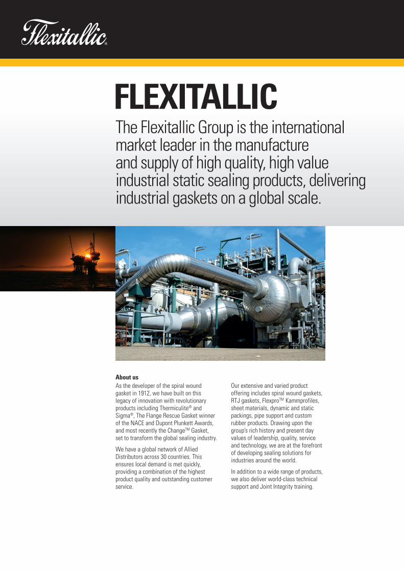
Our extensive and varied productoffering includes spiral wound gaskets,RTJ gaskets, FlexproTM Kammprofiles,sheet materials, dynamic and staticpackings, pipe support and customrubber products. Drawing upon thegroup’s rich history and present dayvalues of leadership, quality, service and technology, we are at the forefrontof developing sealing solutions forindustries around the world.
In addition to a wide range of products,we also deliver world-class technicalsupport and Joint Integrity training.
The Flexitallic Group is the internationalmarket leader in the manufacture and supply of high quality, high valueindustrial static sealing products, deliveringindustrial gaskets on a global scale.
About usAs the developer of the spiral woundgasket in 1912, we have built on thislegacy of innovation with revolutionaryproducts including Thermiculite® andSigma®, The Flange Rescue Gasket winnerof the NACE and Dupont Plunkett Awards,and most recently the ChangeTM Gasket, set to transform the global sealing industry.
We have a global network of AlliedDistributors across 30 countries. Thisensures local demand is met quickly,providing a combination of the highestproduct quality and outstanding customerservice.
FLEXITALLIC

Allied distributors
Based on sales and geographic reach, the Flexitallic Grouphas become the global supplier of industrial gaskets.
Inside IndustryWe pride ourselves on not simply supplyingproducts, but by supporting customers with a detailed knowledge of their industry andapplications, so that products and services are tailored to their specific needs.
This unique approach means that we focus on providing more than just a product, but also a complete solution that adds genuinevalue to our clients.
Global Distribution... Local SupportOur products are distributed through aglobal network of Allied Distributors.
These carefully selected distribution partnersare strategically located within their territoryto deliver the best possible service andproducts to our customers. This approachmeans our products and know-how areavailable to the global industries we service.
Innovative Product RangeWe have a rich history of innovation, which has seen us lead the industry with many new products.
Over the years, our products have gained areputation for quality, reliability and technologythat is second to none.
Customised Engineering SolutionsOur Application Engineering, ProductionEngineering and R&D teams work closelytogether to design, develop and manufacturebespoke sealing solutions.
We have been responsible for a number of trulyrevolutionary products, including Thermiculite®,Sigma® and the Flange Rescue Gasket, whichensure we are able to continually meet the evermore stringent requirements of our customers.
Flexitallic® SafeThe Flexitallic approach to safety is more than a program it’s a way of doing business thatstarted in 1912. We believe our commitment toinnovate, customize and educate adds anotherlevel of protection to our customers’ operations.
From the first Spiral Wound Gasket in 1912 tothe ever evolving applications for Thermiculite®,our goal is to develop materials that push theparameters of heat, pressure and chemicalresistance.
Our Commitment to QualityWe place great emphasis onmaintaining international qualitystandards, and are approved to ISO9001:2008, ISO 14001:2004 and OHSAS18001:2007, API 6A and API 17D, toensure we meet the highest possiblestandards for all our products andservices.
We also invest heavily in test and quality assurance equipment tomaintain our reputation for the highest quality products.
Our materials are subjected to a widerange of tests as specified by statutoryregulations and customer requirements.These approvals enable our customersto make informed choices as to thesuitability of a product for each andevery application.
1.
2. www.flexitallic.eu
The FLEXPRO™ gasket has been providingan extremely tight, reliable seal in a widerange of applications globally since itsdevelopment in Germany over 50 years ago.
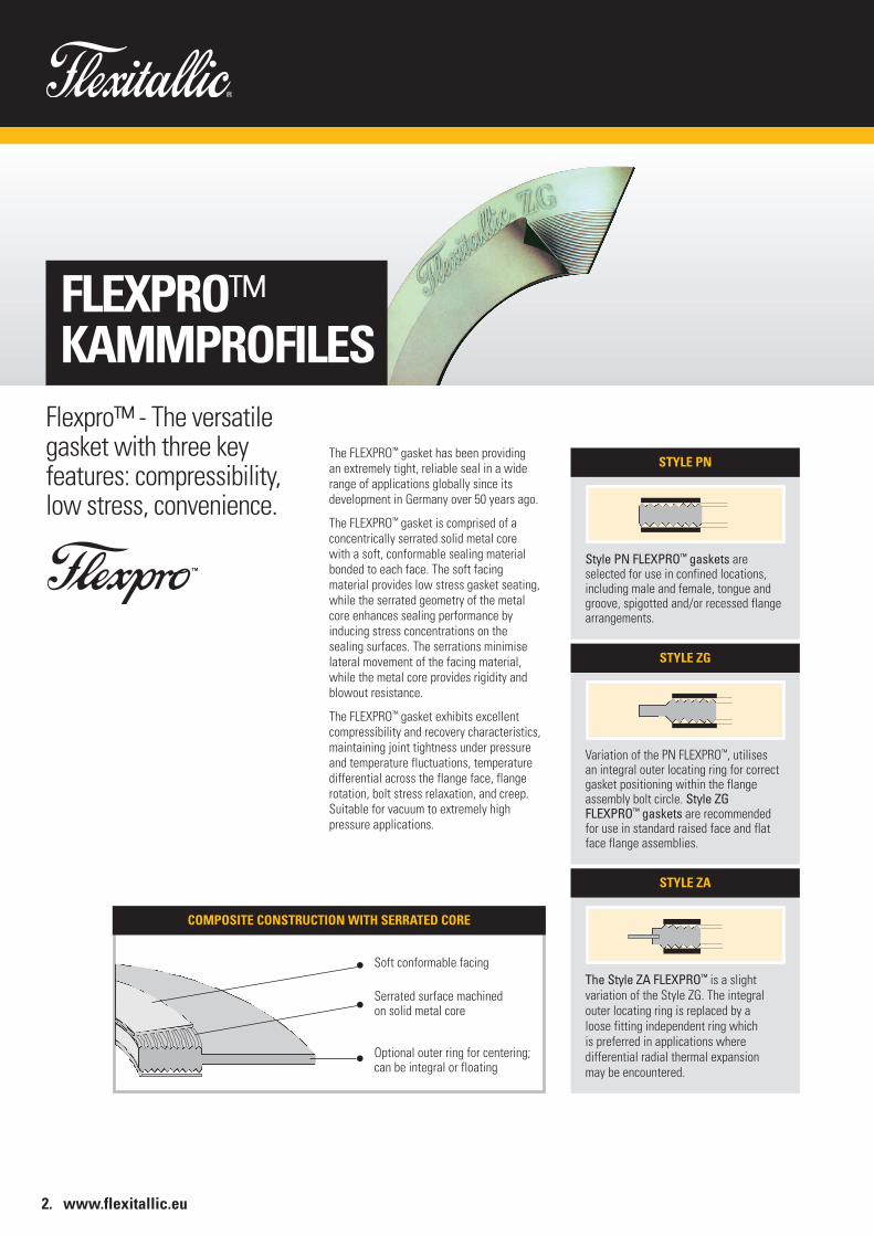
The FLEXPRO™ gasket is comprised of aconcentrically serrated solid metal core with a soft, conformable sealing materialbonded to each face. The soft facingmaterial provides low stress gasket seating,while the serrated geometry of the metalcore enhances sealing performance byinducing stress concentrations on thesealing surfaces. The serrations minimiselateral movement of the facing material,while the metal core provides rigidity andblowout resistance.
The FLEXPRO™ gasket exhibits excellentcompressibility and recovery characteristics,maintaining joint tightness under pressureand temperature fluctuations, temperaturedifferential across the flange face, flangerotation, bolt stress relaxation, and creep.Suitable for vacuum to extremely highpressure applications.
STYLE PN
Style PN FLEXPRO™ gaskets areselected for use in confined locations,including male and female, tongue andgroove, spigotted and/or recessed flangearrangements.
STYLE ZG
Variation of the PN FLEXPRO™, utilisesan integral outer locating ring for correctgasket positioning within the flangeassembly bolt circle. Style ZGFLEXPRO™ gaskets are recommendedfor use in standard raised face and flatface flange assemblies.
STYLE ZA
The Style ZA FLEXPRO™ is a slightvariation of the Style ZG. The integralouter locating ring is replaced by a loose fitting independent ring whichis preferred in applications wheredifferential radial thermal expansion may be encountered.
Flexpro™ - The versatilegasket with three keyfeatures: compressibility,low stress, convenience.
FLEXPRO™KAMMPROFILES
Soft conformable facing
Serrated surface machined on solid metal core
Optional outer ring for centering;can be integral or floating
COMPOSITE CONSTRUCTION WITH SERRATED CORE

FLEXPRO™KAMMPROFILES
3.
Ideal for Shell and Tube style Heat Exchanger Flanges.Although suitable for use on allstandard pipeline flanges in a widerange of difficult applications, theFLEXPRO™ gasket is proving to bereliable, as a cost effective alternativeto metal jacketed gaskets, that arecommonly used in heat exchangerapplications.
Standard Core MaterialsStandard core thickness is 3.0mm; otherthicknesses and materials are readilyavailable to suit specific applications.
Standard Facing MaterialsStandard facing thickness is 0.5mm or 0.75mm (material dependent); otherthicknesses and materials are readilyavailable to suit specific applications.
Flange Surface Finish RequirementsThe ideal flange surface finish for usewith Flexitallic FLEXPRO™ gaskets is 3.2– 6.4μ – metre Ra (125 – 250 μ – inch Ra).
SHELL SIDE TUBE SIDE
1 2 3 4 5
GASKET LOCATIONS1. Floating Head 2. Shell Cover 3. Shell to Tubesheet 4. Tubesheet to Channel Box 5. Channel Box Cover
*While high stresses have been utilised, Flexitallic Engineering should be contacted for operating stresses above 40,000 psi.
CORE MATERIAL
Stainless Steel
Carbon Steel
Aluminium
Monel®
Nickel
Inconel®
Titanium Gr.2
Duplex 2205* (UNS S31803)
MAX. TEMPERATURE
535 - 870oC
535oC
425oC
815oC
650oC
1100oC
1095oC
300oC
FACING MATERIAL MAX. TEMPERATURE SEATING STRESS AT ROOM TEMP
Thermiculite® 1000oC 2500 (17) 72500 (500)*Flexicarb® Flexible Graphite 450oC 2500 (17) 72500 (500)*
Sigma® 260oC 2500 (17) 72500 (500)*Virgin PTFE 260oC 2500 (17) 72500 (500)*Soft Metals Per material Per material Per material
MIN. PSI (MPa) MAX. PSI (MPa)
Use of the Flexitallic FLEXPRO™ gasket willensure a reliable seal, from initial hydrotestthrough difficult operating conditions.
FLEXPRO™ gaskets are suitable for use on TEMAflanges, and when required,pass partition ribscan be supplied in any configuration.
The FLEXPRO™ gasket provides a high integrity,low seating stress seal, and is ideal for heatexchanger applications with limited bolt load or less rigid flanges.
*Duplex is subject to embrittlement between 350°C and 500°C

4. www.flexitallic.eu
FLEXPRO™KAMMPROFILES
Gb a Gs S100 S1000 Tp MAX
387 psi 0.334 14 psi 1802 psi 3888 psi 55000
TABLE 1: PVRC CONSTANTS
m y
2 2500 psi
TABLE 2: ASME CONSTANTS
Independent PVRCtesting confirmssuperior tightness,room temperaturetightness (ROTT),behaviourcharacterisation.
The ROTT behavior characterisation of a gasketconsists of:• Performing a minimum of two ROTT tests
on NPS 4” samples
• Treating and reporting ROTT data on the basis of the Tightness Parameter concept
• Calculating the PVRC Gasket constants, Gb, “a” and Gs, according to the proposed ASTM Standard
• Reporting the gasket constants and characteristics
Constants Gb, “a”, and GsThe PVRC tightness based gasket constants aredetermined from the results of two or more ROTT tests.Constants Gb and “a” together define an initial seatingperformance line. The combined effect of Gb, and “a”is best represented by the value of STp = Tp x Gb x “a”calculated for typical values of Tp such as 100 or 1000. For example S100 = Gb (100)a. Constant Gsindependently represents operation. Low values of Gb,“a”, Gs, S100 and S1000 are favourable.
Performance in ROTT testsThe results of two ROTT tests conducted at TTRL1 onFlexitallic FLEXPRO™ gaskets are shown in Figure 1.
At the highest Part A stress level (S5 - 15160 psi), Tp values above 55000 were obtained. A Tp of 55000corresponds to a Helium leak rate of approximately1 x 10-6 mg/s at a test pressure of 800 psi.
Part B test data indicates that this gasket maintainssuperior tightness during stress cycling.
1Tightness Testing and Research Laboratory - Ecole Polytechnique of Montreal
1 10 100 1000 10000 100000
100000
10000
1000
Gask
et S
tress
, Sg
(psi
)
a = 0.334
Gb = 387
Note: Applied internal pressure (P) for leakage measurements:P = 800 psi points are represented by unfilled markersP = 400 psi points are represented by filled markers
FL09RT01
FL09RT02Gs = 14
Part APart B1Part B2Part B3
Tightness Parameter, Tp
FIGURE 1: ROTT TEST RESULTS
ROTT test procedureThe ROTT test includes a gasket loadsequence (5 stress levels, S1 to S5), calledPart A, which represents the initial jointtightening and gasket seating. The maximumstress level (S5) is 15160 psi for semi-metallic gaskets. Part A is interrupted at its three highest stress levels to run unload-reload sequences, called Parts B1, B2, B3which simulate joint relaxation andre-tightening. At each stress level, heliumleakage is measured (for two pressures in Part A and one pressure in Part B).
ROTT test data are plotted in the form ofGasket Stress, Sg, vs. Tightness Parameter,Tp, on a log-log scale. The tightnessparameter, Tp, is a measure of the ability of an installed gasket to control its leakageperformance in a pressurised flange joint. Tp is proportional to the pressure causing a small leak and inversely proportional to the square of the leak. Higher the Tp value, the tighter the joint. A joint that is 10 timestighter than another leaks 100 times less(at the same pressure).
Gaskets constantsThe calculated gasket constants are reportedin the table below, along with computedvalues of S100, S1000 and the maximum Tp value obtained in the ROTT tests.

FLEXPRO™KAMMPROFILES
5.
Cyclic Service ComparisonDuring operation, unloading of a bolted-gasketed joint can occur due topressurisation, fluctuation in pressure andtemperature, thermal effects, joint relaxation,etc. PVRC test data confirms the superiorability of the FLEXPRO™ gasket to maintaintightness under these cyclic loadingconditions. As shown in the graph, whengasket stress is reduced from 8000 psi to4400 psi, the FLEXPRO™ gasket leaks 100times less than a comparable corrugatedmetal graphite gasket (CMG).A tighter joint is a safer joint!
T3 TightnessThe PVRC developed method for characterisinggasket performance specifies three classes oftightness. T1 (economy), T2 (standard), and T3(tight). A tightness class of T3 represents a massleak rate of helium per unit diameter, of 0.00002mg/sec-mm. This graph shows that the FlexitallicFLEXPRO™ gasket achieves a tightness class of T3 at the lowest seating stress when compared to other types of gaskets. Results are based onPVRC test data, using a gasket with dimensions of 20” ID x 20.5” OD, with 20 x 1” diameter boltsand an assembly efficiency of 0.75. The FlexitallicFLEXPRO™ gasket is ideal for use in applicationswhere limited bolt load and/or light weight flangesare used.
Jacketed CMG FLEXPRO™
Gask
et S
tress
(psi
)HELIUM AT 800 PSI
8000 4400 1050 4400 8000
0.1
0.01
0.001
Leak
age
(mg/
s)
Gasket Stress (psi)
0.0001
1E-05
1E-06
1E-07
Limit of resolution
CMG
FlexitallicFLEXPRO™
FLEXPRO™ leaks100 times less
20 timesless
20 timesless
12000
10000
8000
6000
4000
2000
0
FLEXPRO™KAMMPROFILES
Flange Calculations and Gasket Parameters– EN 1591-1 and EN 13555Driven by national requirements within theEuropean Union for increasing plant efficiency and reducing fugitive emissions the EuropeanStandard EN 1591-1 was first published in 2001.The Standard outlines a calculation method inwhich strength criteria of the individualmechanical components in a bolted joint namely;flanges, bolts and gasket, and importantly leakagecriteria are satisfied for a particular application.The calculation method adopts the premise thatall gasketed bolted flanged connections leak andrequires the user to specify what a permissiblelevel of leakage is for a particular application. Thisis done via the introduction of the concept of thetightness class. At the time of writing EN 1591-1is the only stand alone standardised calculationmethod that includes both stress analysis andtightness proof of a bolted connection.
The calculation requires the input of data specific to the particular applicationin question. The required gasketcharacteristics are generated in accordancewith the European standard EN 13555. The test protocol outlined in EN 13555 is complex and requires the use of costlysophisticated test equipment.
As the leading supplier of technicalsolutions in the field of industrial sealingFlexitallic makes use of the latest innovativematerials technologies and calculationmethodologies to ensure the highest levelsof joint integrity. Gasket characteristics inaccordance with EN13555 are available forwide selection of Flexitallic static sealingproducts. Alternatively Flexitallic canundertake flange calculations in accordancewith EN1591-1 on behalf of the end user.
6. www.flexitallic.eu
GASKET CHARACTERISTICS ACROSS A RANGE OF TEMPERATURES, STRESSESAND PRESSURES, RELATING TO THE FOLLOWING PROPERTIES ARE GENERATED:
QSmax Maximum surface pressure that can be imposed on a gasket before failure occurs
Qmin(L) Minimum gasket surface pressure required for leakage class (L) on initial loading
QSmin(L) Minimum gasket surface pressure required for leakage class (L) after off-loading
LN Leakage tightness classes:
Tightness Class LN: L1.0 L0.1 L0.01 Specific Leakage Rate (mg.s-1.m-1): ≤ 1.0 ≤ 0.1 ≤ 0.01
PQR Creep relaxation factor. Ratio of the original and final surface pressures
ΔeGc Change in gasket thickness due to creep
EG Elastic unloading modulus
αG Coefficient of axial thermal expansion
µG Static friction factor between the gasket and contacting flange face.
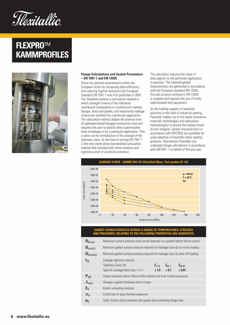
LEAKAGE CURVE - KAMM 316L FG 154x124x4.78mm. Test number 07-133
0 20 40 60 80 100 120 140 160
1.00E+00
1.00E-01
1.00E-02
1.00E-03
1.00E-04
1.00E-05
1.00E-06
1.00E-07
Leak
rate
(mg/
m/s
)
Gasket Stress (MPa)
p = 40 barT = 23°CHe

DIMENSIONALDATA
STYLE ZG
FLEXPRO™ KAMMPROFILESASME B16.20
NOMINAL BORE
GENERAL NOTESDimensions in mm. Tolerances in mm. Figures stated are for information only. Please refer to the current version of the original standards for dimensional information.
NOTES1) Tolerances +/- 0.8mm for all diameters2) There is no Class 400 flanges in NPS ½” through NPS 3” (use Class 600)3) There is no Class 900 flanges in NPS ½” through NPS 2.½” (use Class 1500)4) There is no Class 2500 flanges in NPS 14” and larger
SEALINGOUTER
DIAMETER
CENTERING RING OUTER DIAMETER
INCHES
SEALINGINNER
DIAMETER
½ 15 23.1 33.3 47.8 54.1 Note (2) 54.1 Note (3) 63.5 69.9
¾ 20 28.7 39.6 57.2 66.8 Note (2) 66.8 Note (3) 69.9 76.2
1 25 36.6 47.5 66.8 73.2 Note (2) 73.2 Note (3) 79.5 85.9
1 1/4 32 44.5 60.2 76.2 82.6 Note (2) 82.6 Note (3) 88.9 104.9
1 1/2 40 52.3 69.9 85.9 95.3 Note (2) 95.3 Note (3) 98.6 117.6
2 50 69.9 88.9 104.9 111.3 Note (2) 111.3 Note (3) 143.0 146.1
2 1/2 65 82.6 101.6 124.0 130.3 Note (2) 130.3 Note (3) 165.1 168.4
3 80 98.3 123.7 136.7 149.4 Note (2) 149.4 168.4 174.8 196.9
4 100 123.7 153.9 174.8 181.1 177.8 193.8 206.5 209.6 235.0
5 125 150.9 182.6 196.9 215.9 212.9 241.3 247.7 254.0 279.4
6 150 177.8 212.6 222.3 251.0 247.7 266.7 289.1 282.7 317.5
8 200 228.6 266.7 279.4 308.1 304.8 320.8 358.9 352.6 387.4
10 250 282.7 320.8 339.9 362.0 358.9 400.1 435.1 435.1 476.3
12 300 339.6 377.7 409.7 422.4 419.1 457.2 498.6 520.7 549.4
14 350 371.6 409.7 450.9 485.9 482.6 492.3 520.7 577.9 Note (4)
16 400 422.4 466.6 514.4 539.8 536.7 565.2 574.8 641.4 Note (4)
18 450 479.3 530.1 549.4 596.9 593.9 612.9 638.3 704.9 Note (4)
20 500 530.1 580.9 606.6 654.1 647.7 682.8 698.5 755.7 Note (4)
24 600 631.7 682.5 717.6 774.7 768.4 790.7 838.2 901.7 Note (4)
MM 150 Class 300 Class 400 Class 600 Class 900 Class 1500 Class 2500 Class
STYLE ZA
7.
DIMENSIONALDATA
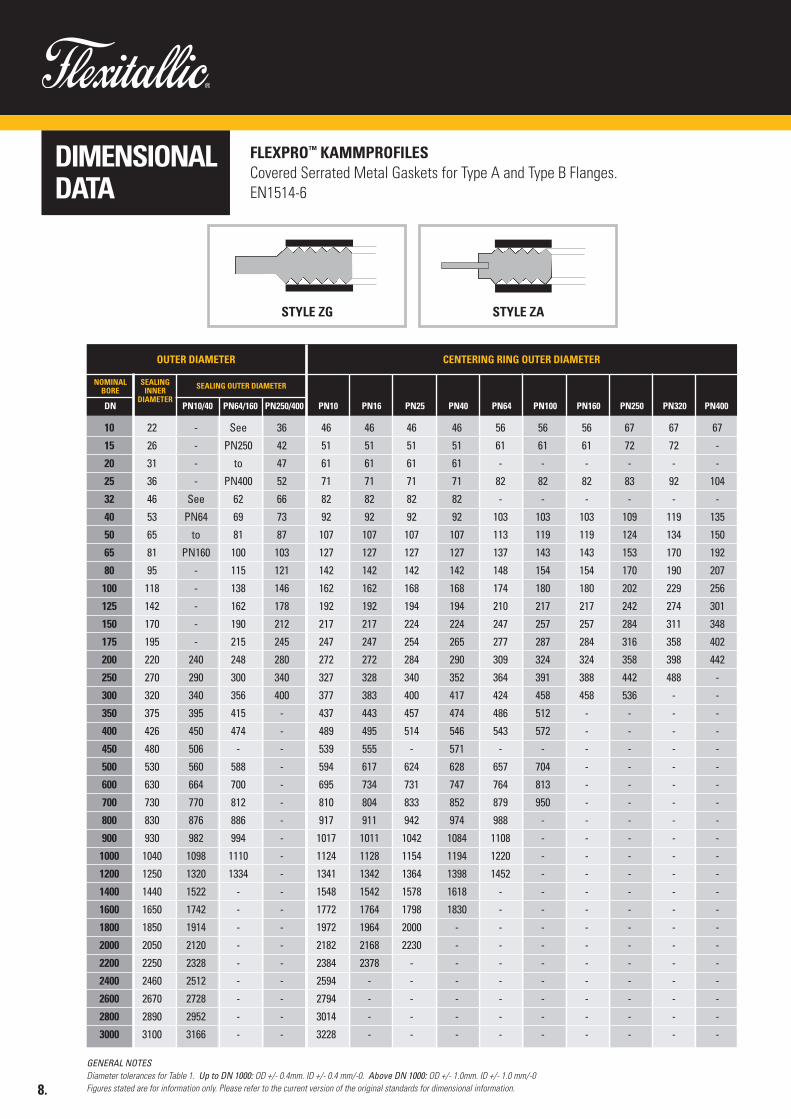
FLEXPRO™ KAMMPROFILESCovered Serrated Metal Gaskets for Type A and Type B Flanges. EN1514-6
GENERAL NOTESDiameter tolerances for Table 1. Up to DN 1000: OD +/- 0.4mm. ID +/- 0.4 mm/-0. Above DN 1000: OD +/- 1.0mm. ID +/- 1.0 mm/-0Figures stated are for information only. Please refer to the current version of the original standards for dimensional information.
OUTER DIAMETER CENTERING RING OUTER DIAMETER
DN PN10 PN16 PN25 PN40 PN64 PN320
SEALINGINNER
DIAMETERPN10/40
10 22 - See 36 46 46 46 46 56 56 56 67 67 67
15 26 - PN250 42 51 51 51 51 61 61 61 72 72 -
20 31 - to 47 61 61 61 61 - - - - - -
25 36 - PN400 52 71 71 71 71 82 82 82 83 92 104
32 46 See 62 66 82 82 82 82 - - - - - -
40 53 PN64 69 73 92 92 92 92 103 103 103 109 119 135
50 65 to 81 87 107 107 107 107 113 119 119 124 134 150
65 81 PN160 100 103 127 127 127 127 137 143 143 153 170 192
80 95 - 115 121 142 142 142 142 148 154 154 170 190 207
100 118 - 138 146 162 162 168 168 174 180 180 202 229 256
125 142 - 162 178 192 192 194 194 210 217 217 242 274 301
150 170 - 190 212 217 217 224 224 247 257 257 284 311 348
175 195 - 215 245 247 247 254 265 277 287 284 316 358 402
200 220 240 248 280 272 272 284 290 309 324 324 358 398 442
250 270 290 300 340 327 328 340 352 364 391 388 442 488 -
300 320 340 356 400 377 383 400 417 424 458 458 536 - -
350 375 395 415 - 437 443 457 474 486 512 - - - -
400 426 450 474 - 489 495 514 546 543 572 - - - -
450 480 506 - - 539 555 - 571 - - - - - -
500 530 560 588 - 594 617 624 628 657 704 - - - -
600 630 664 700 - 695 734 731 747 764 813 - - - -
700 730 770 812 - 810 804 833 852 879 950 - - - -
800 830 876 886 - 917 911 942 974 988 - - - - -
900 930 982 994 - 1017 1011 1042 1084 1108 - - - - -
1000 1040 1098 1110 - 1124 1128 1154 1194 1220 - - - - -
1200 1250 1320 1334 - 1341 1342 1364 1398 1452 - - - - -
1400 1440 1522 - - 1548 1542 1578 1618 - - - - - -
1600 1650 1742 - - 1772 1764 1798 1830 - - - - - -
1800 1850 1914 - - 1972 1964 2000 - - - - - - -
2000 2050 2120 - - 2182 2168 2230 - - - - - - -
2200 2250 2328 - - 2384 2378 - - - - - - - -
2400 2460 2512 - - 2594 - - - - - - - - -
2600 2670 2728 - - 2794 - - - - - - - - -
2800 2890 2952 - - 3014 - - - - - - - - -
3000 3100 3166 - - 3228 - - - - - - - - -
PN64/160 PN250/400 PN100 PN160 PN250 PN400
STYLE ZG STYLE ZA
NOMINALBORE
SEALING OUTER DIAMETER
8.
DIMENSIONALDATA
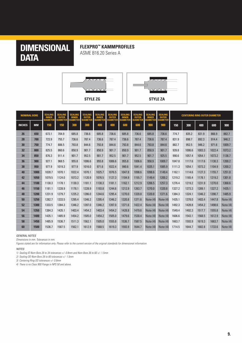
FLEXPRO™ KAMMPROFILESASME B16.20 Series A
NOMINAL BORE
GENERAL NOTESDimensions in mm. Tolerances in mm.Figures stated are for information only. Please refer to the current version of the original standards for dimensional information.
NOTES1) Sealing ID Nom Bore 26 to 34 tolerances +/- 0.8mm and Nom Bore 36 to 60 +/- 1.5mm2) Sealing OD Nom Bore 26 to 60 tolerances +/- 1.5mm3) Centering Ring OD tolerances =/- 0.8mm4) There is no Class 900 Flange in NPS 50 and above.
SEALINGOUTER
DIAMETER
150
SEALINGOUTER
DIAMETER
300
SEALINGOUTER
DIAMETER
400
CENTERING RING OUTER DIAMETER
INCHES
SEALINGINNER
DIAMETER
150
SEALINGINNER
DIAMETER
300
SEALINGINNER
DIAMETER
400
26 650 673.1 704.9 685.8 736.6 685.8 736.6 685.8 736.6 685.8 736.6 774.7 835.2 831.9 866.9 882.7
28 700 723.9 755.7 736.6 787.4 736.6 787.4 736.6 787.4 736.6 787.4 831.9 898.7 892.3 914.4 946.2
30 750 774.7 806.5 793.8 844.6 793.8 844.6 793.8 844.6 793.8 844.6 882.7 952.5 946.2 971.6 1009.7
32 800 825.5 860.6 850.9 901.7 850.9 901.7 850.9 901.7 850.9 901.7 939.8 1006.6 1003.3 1022.4 1073.2
34 850 876.3 911.4 901.7 952.5 901.7 952.5 901.7 952.5 901.7 925.5 990.6 1057.4 1054.1 1073.2 1136.7
36 900 927.1 968.5 955.8 1006.6 955.8 1006.6 955.8 1006.6 958.9 1009.7 1047.8 1117.6 1117.6 1130.3 1200.2
38 950 977.9 1019.3 977.9 1016.0 971.6 1022.4 990.6 1041.4 1035.1 1085.9 1111.3 1054.1 1073.2 1104.9 1200.2
40 1000 1028.7 1070.1 1022.4 1070.1 1025.7 1076.5 1047.8 1098.6 1098.6 1149.4 1162.1 1114.6 1127.3 1155.7 1251.0
42 1050 1079.5 1124.0 1073.2 1120.9 1076.5 1127.3 1104.9 1155.7 1149.4 1200.2 1219.2 1165.4 1178.1 1219.2 1301.8
44 1100 1130.3 1178.1 1130.3 1181.1 1130.3 1181.1 1162.1 1212.9 1206.5 1257.3 1276.4 1219.2 1231.9 1270.0 1368.6
46 1150 1181.1 1228.9 1178.1 1228.9 1193.8 1244.6 1212.9 1263.7 1270.0 1320.8 1327.2 1273.3 1289.1 1327.2 1435.1
48 1200 1231.9 1279.7 1235.2 1286.0 1244.6 1295.4 1270.0 1320.8 1320.8 1371.6 1384.3 1324.1 1346.2 1390.7 1485.9
50 1250 1282.7 1333.5 1295.4 1346.2 1295.4 1346.2 1320.8 1371.6 Note (4) Note (4) 1435.1 1378.0 1403.4 1447.8 Note (4)
52 1300 1333.5 1384.3 1346.2 1397.0 1346.2 1397.0 1371.6 1422.4 Note (4) Note (4) 1492.3 1428.8 1454.2 1498.6 Note (4)
54 1350 1384.3 1435.1 1403.4 1454.2 1403.4 1454.2 1428.8 1479.6 Note (4) Note (4) 1549.4 1492.3 1517.7 1555.8 Note (4)
56 1400 1435.1 1485.9 1454.2 1505.0 1454.2 1505.0 1479.6 1530.4 Note (4) Note (4) 1606.6 1543.1 1568.5 1612.9 Note (4)
58 1450 1485.9 1536.7 1511.3 1562.1 1505.0 1555.8 1536.7 1587.5 Note (4) Note (4) 1663.7 1593.9 1619.3 1663.7 Note (4)
60 1500 1536.7 1587.5 1562.1 1612.9 1568.5 1619.3 1593.9 1644.7 Note (4) Note (4) 1714.5 1644.7 1682.8 1733.6 Note (4)
SEALINGOUTER
DIAMETER
600
SEALINGINNER
DIAMETER
600
SEALINGOUTER
DIAMETER
900
SEALINGINNER
DIAMETER
900MM 150 300 400 600 900
STYLE ZG STYLE ZA
9.
DIMENSIONALDATA
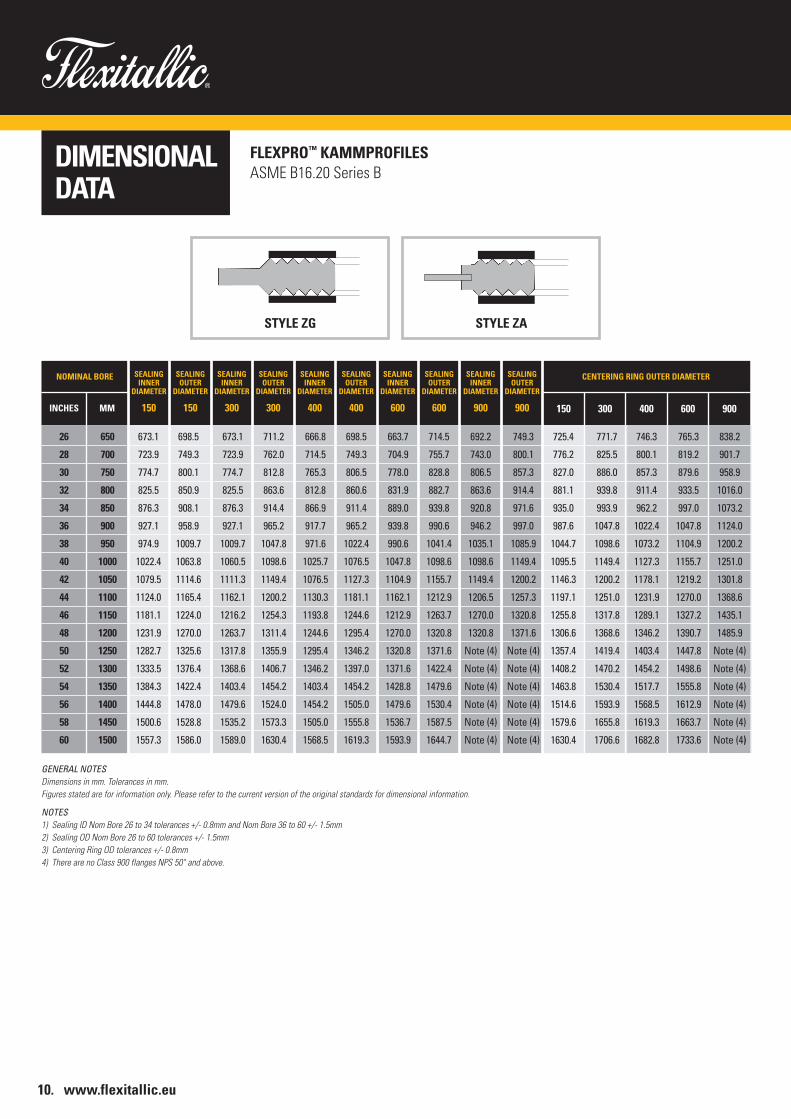
FLEXPRO™ KAMMPROFILESASME B16.20 Series B
NOMINAL BORE
GENERAL NOTESDimensions in mm. Tolerances in mm.Figures stated are for information only. Please refer to the current version of the original standards for dimensional information.
NOTES1) Sealing ID Nom Bore 26 to 34 tolerances +/- 0.8mm and Nom Bore 36 to 60 +/- 1.5mm2) Sealing OD Nom Bore 26 to 60 tolerances +/- 1.5mm3) Centering Ring OD tolerances +/- 0.8mm4) There are no Class 900 flanges NPS 50" and above.
SEALINGOUTER
DIAMETER
150
SEALINGOUTER
DIAMETER
300
SEALINGOUTER
DIAMETER
400
CENTERING RING OUTER DIAMETER
INCHES
SEALINGINNER
DIAMETER
150
SEALINGINNER
DIAMETER
300
SEALINGINNER
DIAMETER
400
26 650 673.1 698.5 673.1 711.2 666.8 698.5 663.7 714.5 692.2 749.3 725.4 771.7 746.3 765.3 838.2
28 700 723.9 749.3 723.9 762.0 714.5 749.3 704.9 755.7 743.0 800.1 776.2 825.5 800.1 819.2 901.7
30 750 774.7 800.1 774.7 812.8 765.3 806.5 778.0 828.8 806.5 857.3 827.0 886.0 857.3 879.6 958.9
32 800 825.5 850.9 825.5 863.6 812.8 860.6 831.9 882.7 863.6 914.4 881.1 939.8 911.4 933.5 1016.0
34 850 876.3 908.1 876.3 914.4 866.9 911.4 889.0 939.8 920.8 971.6 935.0 993.9 962.2 997.0 1073.2
36 900 927.1 958.9 927.1 965.2 917.7 965.2 939.8 990.6 946.2 997.0 987.6 1047.8 1022.4 1047.8 1124.0
38 950 974.9 1009.7 1009.7 1047.8 971.6 1022.4 990.6 1041.4 1035.1 1085.9 1044.7 1098.6 1073.2 1104.9 1200.2
40 1000 1022.4 1063.8 1060.5 1098.6 1025.7 1076.5 1047.8 1098.6 1098.6 1149.4 1095.5 1149.4 1127.3 1155.7 1251.0
42 1050 1079.5 1114.6 1111.3 1149.4 1076.5 1127.3 1104.9 1155.7 1149.4 1200.2 1146.3 1200.2 1178.1 1219.2 1301.8
44 1100 1124.0 1165.4 1162.1 1200.2 1130.3 1181.1 1162.1 1212.9 1206.5 1257.3 1197.1 1251.0 1231.9 1270.0 1368.6
46 1150 1181.1 1224.0 1216.2 1254.3 1193.8 1244.6 1212.9 1263.7 1270.0 1320.8 1255.8 1317.8 1289.1 1327.2 1435.1
48 1200 1231.9 1270.0 1263.7 1311.4 1244.6 1295.4 1270.0 1320.8 1320.8 1371.6 1306.6 1368.6 1346.2 1390.7 1485.9
50 1250 1282.7 1325.6 1317.8 1355.9 1295.4 1346.2 1320.8 1371.6 Note (4) Note (4) 1357.4 1419.4 1403.4 1447.8 Note (4)
52 1300 1333.5 1376.4 1368.6 1406.7 1346.2 1397.0 1371.6 1422.4 Note (4) Note (4) 1408.2 1470.2 1454.2 1498.6 Note (4)
54 1350 1384.3 1422.4 1403.4 1454.2 1403.4 1454.2 1428.8 1479.6 Note (4) Note (4) 1463.8 1530.4 1517.7 1555.8 Note (4)
56 1400 1444.8 1478.0 1479.6 1524.0 1454.2 1505.0 1479.6 1530.4 Note (4) Note (4) 1514.6 1593.9 1568.5 1612.9 Note (4)
58 1450 1500.6 1528.8 1535.2 1573.3 1505.0 1555.8 1536.7 1587.5 Note (4) Note (4) 1579.6 1655.8 1619.3 1663.7 Note (4)
60 1500 1557.3 1586.0 1589.0 1630.4 1568.5 1619.3 1593.9 1644.7 Note (4) Note (4) 1630.4 1706.6 1682.8 1733.6 Note (4)
SEALINGOUTER
DIAMETER
600
SEALINGINNER
DIAMETER
600
SEALINGOUTER
DIAMETER
900
SEALINGINNER
DIAMETER
900MM 150 300 400 600 900
STYLE ZG STYLE ZA
10. www.flexitallic.eu
DIMENSIONALDATA
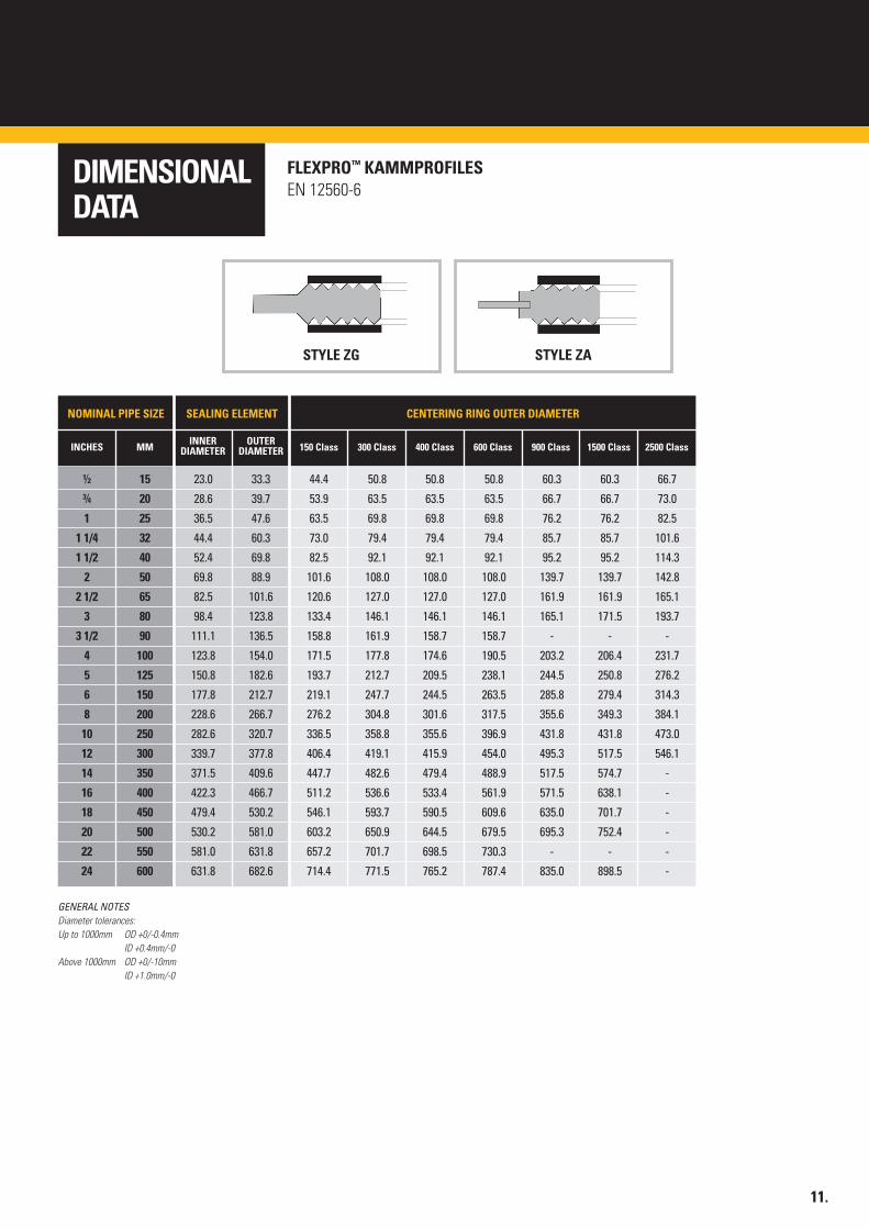
FLEXPRO™ KAMMPROFILESEN 12560-6
STYLE ZG STYLE ZA
NOMINAL PIPE SIZE
GENERAL NOTESDiameter tolerances:Up to 1000mm OD +0/-0.4mm
ID +0.4mm/-0Above 1000mm OD +0/-10mm
ID +1.0mm/-0
OUTERDIAMETER
CENTERING RING OUTER DIAMETER
INCHES INNERDIAMETER
½ 15 23.0 33.3 44.4 50.8 50.8 50.8 60.3 60.3 66.7
¾ 20 28.6 39.7 53.9 63.5 63.5 63.5 66.7 66.7 73.0
1 25 36.5 47.6 63.5 69.8 69.8 69.8 76.2 76.2 82.5
1 1/4 32 44.4 60.3 73.0 79.4 79.4 79.4 85.7 85.7 101.6
1 1/2 40 52.4 69.8 82.5 92.1 92.1 92.1 95.2 95.2 114.3
2 50 69.8 88.9 101.6 108.0 108.0 108.0 139.7 139.7 142.8
2 1/2 65 82.5 101.6 120.6 127.0 127.0 127.0 161.9 161.9 165.1
3 80 98.4 123.8 133.4 146.1 146.1 146.1 165.1 171.5 193.7
3 1/2 90 111.1 136.5 158.8 161.9 158.7 158.7 - - -
4 100 123.8 154.0 171.5 177.8 174.6 190.5 203.2 206.4 231.7
5 125 150.8 182.6 193.7 212.7 209.5 238.1 244.5 250.8 276.2
6 150 177.8 212.7 219.1 247.7 244.5 263.5 285.8 279.4 314.3
8 200 228.6 266.7 276.2 304.8 301.6 317.5 355.6 349.3 384.1
10 250 282.6 320.7 336.5 358.8 355.6 396.9 431.8 431.8 473.0
12 300 339.7 377.8 406.4 419.1 415.9 454.0 495.3 517.5 546.1
14 350 371.5 409.6 447.7 482.6 479.4 488.9 517.5 574.7 -
16 400 422.3 466.7 511.2 536.6 533.4 561.9 571.5 638.1 -
18 450 479.4 530.2 546.1 593.7 590.5 609.6 635.0 701.7 -
20 500 530.2 581.0 603.2 650.9 644.5 679.5 695.3 752.4 -
22 550 581.0 631.8 657.2 701.7 698.5 730.3 - - -
24 600 631.8 682.6 714.4 771.5 765.2 787.4 835.0 898.5 -
MM 150 Class 300 Class 400 Class 600 Class 900 Class 1500 Class 2500 Class
SEALING ELEMENT
11.

12. www.flexitallic.eu
HYBRID AND SPECIALDESIGNS
Flexitallic processes eliminate potentialleakage paths at weld location.
Special shapes. Special shapes.
Standard Flexpro™ Design ProfileWhenever possible Flexitallic recommendthe use of a single piece constructionserrated core (no welds), however, in many instances the size of gasket required is larger than the standard commerciallyavailable sheet material. In these instances,strip material is ring rolled and weldedtogether using the minimum number ofwelds possible. Flexitallic ensure that the ends of the ring-rolled metal strip are carefully aligned, both vertically and horizontally, before full penetrationfusion welding. This process eliminates anypotential leakage paths in the weld location and minimises the heat affected zone.
After careful dressing of the weld concentricserrations are machined on the ring. Thiseliminates any potential high and/or low spots in the weld area.
Lower cost manufacturing routes involvingring-rolling and welding of pre-serratedmetal strip, can result in the integrity of the gasket being compromised (leakagepaths at weld locations).
Serration ProfilesFlexitallic can manufacture Flexpro™ gaskets withvarious serration profiles. The standard Flexitallicshallow profile has been designed to effect a highintegrity seal when covered with any one of a range of facing materials and thicknesses. Other serrationprofiles as defined by different international orcustomer standards are available.
Special ShapesFlexitallic have designed and built a number of serrationprofiling machine tools that provide the capability of machining complex shapes while maintaining theconcentric serrations on the sealing faces. Theseshapes can include oval, obround, rectangular andirregular shapes which are often required for manholes,special access door seals and fin fan cooler box covers.The Flexpro™ core can be supplied in a wide range of thicknesses from 2.0mm upwards.
The FlexproT™ design is especially suited for use in connections with narrow radial widths commonlyfound in fin fan plug gaskets and other applicationswhere space is limited such as floating head and valve body and bonnet locations.
In addition to complex shapes, Flexitallic havesuccessfully provided Flexpro™ kammprofile gaskets for use on misaligned flanged connections. These‘wedge’ shaped gasket are machined to meet a specific misalignment angle.
Pass BarsThe Flexpro™ kammprofile section iscommonly supplied in pass bar form and incorporated into the tube side of multi-pass heat exchanger gaskets.
Hybrid DesignsFor difficult sealing applications, hybridtechnology can be applied to provide a highintegrity assembly. Flexitallic can providesealing solutions where Flexpro™sealingtechnology is combined with other gasketstyles such as spiral wound and Changegaskets. The metal core of the Flexpro™
section of the gasket provides additional sealintegrity, compression limitation and rigidity.
For difficult and special applications please contact the Flexitallic ApplicationsEngineering team.
Re-Facing Flexpro™ GasketsTypically a gasket is used only once, however,when using large diameter or expensive corematerial it may be cost effective to re-faceand re-use the Flexpro™ gasket. This servicecan provided by Flexitallic or undertaken on site by suitable personnel followingappropriate training.

SUPERIORPERFORMANCEBY DESIGN
13.
WHY FLEXPRO™ KAMMPROFILE GASKETS?
Proven Design Many years of proven success in sealing difficult applications.
Superior Sealing Correct material selection provides longer service life, no need to ‘hot torque’, Tightness and Safety reduced emissions and reduced maintenance requirements.
Low Seating Stress Ideal for light flanges with limited bolt load, as well as highly loaded flanges.
Different Shapes Flexitallic production methods provide the capability of manufacturing a wide range of sizes in circular and non-circular shapes to suit a wide range of flange types.
Wide Range FlexproTM gasket metal cores and soft facings are selected from a wide range of Materials of materials to suit specific applications.
Wide Pressure Range Suitable for use on all standard flange pressure classes and norms.
Wide Temperature Range Suitable for use in cryogenic service up to 1000°C
Conformable The soft conformable sealing faces of the FlexproTM gaskets, areSealing Surfaces more tolerant to smooth and or damaged flange sealing faces.
Reproducible The Flexitallic manufacturing processes provide a highly repeatable processConstruction from one manufacturing batch to another.
Easy to Handle The rigid and stable core of the FlexproTM gasket facilitates easy handling and Install and installation, with reduced risk of damage to the gasket.
Fire Safe Material specific, FlexproTM gaskets are API-6FB Fire Safe.
Re-usable FlexproTM gaskets can be re-faced and re-used.
Replaces Double FlexproTM gaskets are a direct replacement for double jacketed gaskets. Jacketed Gaskets Note: Where Nubbins (stress raisers) are present, please check with Flexitallic Applications Engineering Team.
Space Limitations FlexproTM gaskets can be manufactured with narrow seal land widths
Cost Effective Longer service life, less maintenance, reduced emissions.

Desi
gned
by
Clea
r Des
ign
(Nor
th).
E. in
fo@
clea
rweb
site
.co.
ukAbout The Flexitallic GroupThe Flexitallic Group is a global leader in specialised sealingsolutions and products serving the oil and gas, power generation,chemical and petrochemical industries in emerging and developedmarkets. Focused on the upstream, downstream and powergeneration sectors, it has operations in France, the United States,Canada, Mexico, the United Kingdom, Germany, the United ArabEmirates, Saudi Arabia, Kazakhstan and China plus a network ofworldwide licensing partners and distributors.www.theflexitallicgroup.com
FLEX005–AUG2016–REV1
CHINAFlexitallic Sealing Technology(Suzhou) Co. LtdBuilding 3, South 688 Pangjin RoadWuJiang Export Processing Zone WuJiang CHINA 215200Tel. +86 512 6303 2839Fax. +86 512 6303 2879www.china.flexitallic.com
FRANCESiem Supranite a Flexitallic Company250 bis rue du Fg St Honoré75008 ParisFRANCETel. +33 (0)1 48 88 88 88Fax. +33 (0)1 47 66 88 44www.siem.fr
UNITED KINGDOMFlexitallic LtdScandinavia MillHunsworth LaneCleckheatonWest Yorkshire, BD19 4LNUKTel. +44 1274 851273Fax. +44 1274 300303www.flexitallic.eu
Branches also in Aberdeen,Middlesbrough, EllesmerePort and Cardiff.
UNITED STATESFlexitallic L.P.6915 Highway 225Deer ParkTexas 77536 USA Tel. +1 281 604 2400Fax. +1 281 604 2415www.flexitallic.com
CANADAFlexitallic Inc4340 - 78 AvenueEdmonton Alberta, T6B 3J5CANADATel. +780 466 5050Fax. +780 465 1177www.flexitallic.ca
UNITED ARAB EMIRATESFlexitallic LLC Plot 108, Road EAl Hamra Industrial AreaRas Al Khaimah,UNITED ARAB EMIRATESTel. +971 (0)7 243 4305Fax. +971 (0)7 243 4306www.flexitallic.ae
UNITED STATESCustom Rubber Products2625 BenningtonHoustonTexas 77093USATel. +1 713 691 2211Fax. +1 713 691 3005www.customrubber.com
KAZAKHSTANNovus Sealing Caspian LLPa Flexitallic Joint Venture7v Atambayev St.Atyrau 060005REPUBLIC OF KAZAKHSTANTel: +7 7122 309936Fax: +7 7122 309937www.novussealingcaspian.com
GERMANYFlexitallic GmbH Halskestr. 4a47877 WillichGERMANYTel: +49 (0) 2154 95363-0Fax: +49 (0) 2154 95363-29www.flexitallic-gmbh.de
SINGAPOREFlexitallic Ltd Singapore BranchLevel 42 Suntec Tower Three8 Temasek BoulevardSINGAPORE038988Tel: +65 68663638www.flexitallic.eu
www.flexitallic.eu