Embed Size (px)
Citation preview
Flight Manual ASW 28-18 E Flight Manual
Issue: 10.02.2005 Michael Greiner LBA-Appr. Revision: TN9 / 6.11.08
2.5
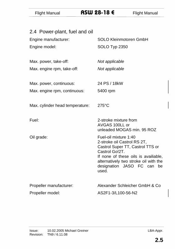
2.4 Power-plant, fuel and oil Engine manufacturer: SOLO Kleinmotoren GmbH
Engine model: SOLO Typ 2350
Max. power, take-off: Not applicable
Max. engine rpm, take-off: Not applicable
Max. power, continuous: 24 PS / 18kW
Max. engine rpm, continuous: 5400 rpm
Max. cylinder head temperature: 275°C
Fuel: 2-stroke mixture from AVGAS 100LL or unleaded MOGAS min. 95 ROZ
Oil grade: Fuel-oil mixture 1:40 2-stroke oil Castrol RS 2T, Castrol Super TT, Castrol TTS or Castrol Go!2T. If none of these oils is availiable, alternatively two stroke oil with the designation JASO FC can be used.
Propeller manufacturer: Alexander Schleicher GmbH & Co
Propeller model: AS2F1-3/L100-56-N2
Flight Manual ASW 28 E Flight Manual
LBA-App, Issue: 10.02.2005 Michael Greiner Revision: TN9 / 6.11.08
2.6
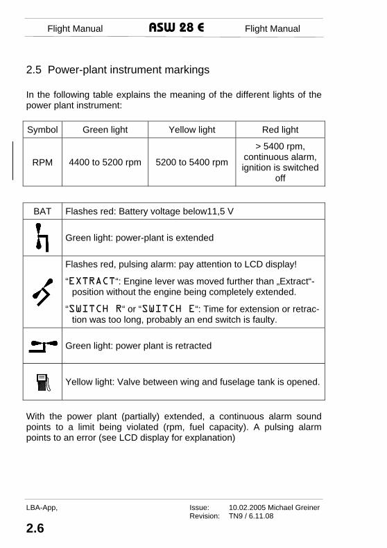
2.5 Power-plant instrument markings In the following table explains the meaning of the different lights of the power plant instrument:
Symbol Green light Yellow light Red light
RPM 4400 to 5200 rpm 5200 to 5400 rpm
> 5400 rpm, continuous alarm,ignition is switched
off
BAT Flashes red: Battery voltage below11,5 V
Green light: power-plant is extended
Flashes red, pulsing alarm: pay attention to LCD display!
“EXTRACT“: Engine lever was moved further than „Extract“-position without the engine being completely extended.
“SWITCH R“ or “SWITCH E“: Time for extension or retrac-tion was too long, probably an end switch is faulty.
Green light: power plant is retracted
Yellow light: Valve between wing and fuselage tank is opened.
With the power plant (partially) extended, a continuous alarm sound points to a limit being violated (rpm, fuel capacity). A pulsing alarm points to an error (see LCD display for explanation)
Flight Manual ASW 28-18 E Flight Manual
Issue: 10.02.2005 Michael Greiner LBA-Appr. Revision: TN9 / 6.11.08
4.19
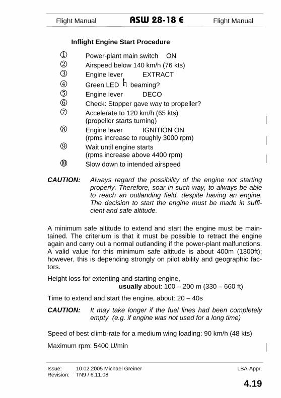
Inflight Engine Start Procedure
1 Power-plant main switch ON 2 Airspeed below 140 km/h (76 kts) 3 Engine lever EXTRACT 4 Green LED beaming? 5 Engine lever DECO 6 Check: Stopper gave way to propeller? 7 Accelerate to 120 km/h (65 kts)
(propeller starts turning) 8 Engine lever IGNITION ON
(rpms increase to roughly 3000 rpm) 9 Wait until engine starts
(rpms increase above 4400 rpm) Slow down to intended airspeed
CAUTION: Always regard the possibility of the engine not starting
properly. Therefore, soar in such way, to always be able to reach an outlanding field, despite having an engine. The decision to start the engine must be made in suffi-cient and safe altitude.
A minimum safe altitude to extend and start the engine must be main-tained. The criterium is that it must be possible to retract the engine again and carry out a normal outlanding if the power-plant malfunctions. A valid value for this minimum safe altitude is about 400m (1300ft); however, this is depending strongly on pilot ability and geographic fac-tors. Height loss for extenting and starting engine,
usually about: 100 – 200 m (330 – 660 ft) Time to extend and start the engine, about: 20 – 40s CAUTION: It may take longer if the fuel lines had been completely
empty (e.g. if engine was not used for a long time) Speed of best climb-rate for a medium wing loading: 90 km/h (48 kts)
Maximum rpm: 5400 U/min
Flight Manual ASW 28 E Flight Manual
LBA-Appr, Issue: 10.02.2005 Michael Greiner Revision:
4.20
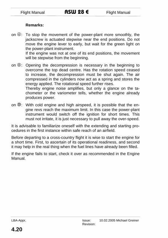
Remarks:
on 4: To stop the movement of the power-plant more smoothly, the jackscrew is actuated stepwise near the end positions. Do not move the engine lever to early, but wait for the green light on the power-plant instrument.
If the engine was not at one of its end positions, the movement will be stepwise from the beginning.
on 8: Opening the decompression is necessary in the beginning to
overcome the top dead centre. Has the rotation speed ceased to increase, the decompression must be shut again. The air compressed in the cylinders now act as a spring and stores the energy applied. The rotational speed further rises.
Thereby engine noise amplifies, but only a glance on the ta-chometer or the variometer tells, whether the engine already produces power.
on : With cold engine and high airspeed, it is possible that the en-
gine revs reach the maximum limit. In this case the power-plant instrument would switch off the ignition for short times. This must not irritate, it is just necessary to pull away the over-speed.
It is advisable to familiarize oneself with the extending and starting pro-cedures in the first instance within safe reach of an airfield. Before departing to a cross-country flight it is wise to start the engine for a short time. First, to ascertain of its operational readiness, and second it may help in the real thing when the fuel lines have already been filled. If the engine fails to start, check it over as recommended in the Engine Manual.
Flight Manual ASW 28-18 E Flight Manual
Issue: 10.02.2005 Michael Greiner LBA-Appr. Revision:
4.21
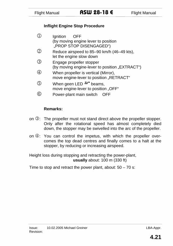
Inflight Engine Stop Procedure
1 Ignition OFF (by moving engine lever to position „PROP STOP DISENGAGED“)
2 Reduce airspeed to 85–90 km/h (46–49 kts), let the engine slow down
3 Engage propeller stopper (by moving engine-lever to position „EXTRACT“)
4 When propeller is vertical (Mirror), move engine-lever to position „RETRACT“
5 When geen LED beams, move engine-lever to position „OFF“
6 Power-plant main switch OFF
Remarks:
on 3: The propeller must not stand direct above the propeller stopper. Only after the rotational speed has almost completely died down, the stopper may be swivelled into the arc of the propeller.
on 4: You can control the impetus, with which the propeller over-
comes the top dead centres and finally comes to a halt at the stopper, by reducing or increasing airspeed.
Height loss during stopping and retracting the power-plant,
usually about: 100 m (330 ft) Time to stop and retract the power plant, about: 50 – 70 s:

Flight Manual ASW 28 E Flight Manual
LBA-Appr, Issue: 10.02.2005 Michael Greiner Revision: TN9 / 6.11.08
4.22
Powered Flight CAUTION: Medical investigations have shown, how much the interior
noise of powered sailplanes with retractable engines can harm the unprotected ear. Therefore always wear ear protection during powered flight. To compensate for this, turn the radio louder.
The largest cruising range can be achieved with a saw-tooth pattern. That means, to fly under power with the speed of the best climb-rate and glide with retracted engine and the speed of the best glide-ratio. See section 5.3.6 for performance information. CAUTION: While the engine is running, the engine control device
must continuously stay on! Switching on and off with the engine running, can lead to
unpredictable reactions of the electronics. Pay attention to the fuel amount in the fuselage tank, and – if installed – open the valve of the wing-tanks in time. CAUTION: The wing tanks valve will switch off automatically only if
the tank selector is set to “AUTO”. With manual position “ON” selected the valve will not close when the fuselage tank is full and fuel will be lost via the ventilation! There-fore, the fuel level indicator must be monitored and the wing tank valves closed in good time.
A detailed description of the power-plant instrument is given under sec-tion 7.12.

Flight Manual ASW 28-18 E Flight Manual
Issue: 10.02.2005 Michael Greiner Revision: TN9 / 6.11.08
5.13
5.3.6 Performance with engine running The performance depends strongly upon altitude, temperature and wing loading. The following values refer to standard atmosphere and sea level.
Climb Without water ballast a best climb rate of 1,2m/s (236ft/min) can be achieved at an airspeed of VY = 90km/h (48kts; 56mph).
Horizontal flight The maximum speed for level flight without water ballast at sea level is VH = 120km/h (64 kts; 75 mph). The airspeed for horizontal flight de-creases with height. An altitude of 2800m (9200 ft) MSL (standard atmosphere) can be main-tained with maximum wing loading and an airspeed of VH = VY = 90km/h (48kts; 56mph).
Flight with high wing loading With full wing loading the speed of best climb VY is approx. 5 – 8 km/h (3 – 4 kts; 3 – 5 mph) higher than the above mentioned values. Still the the climb rate is considerable lower, therefore it is recommended to dump the water ballast. With full wing loading the speed for level flight at sea level is approx. VH = 120km/h (64 kts; 75 mph).
Flight Manual ASW 28 E Flight Manual
Issue: 10.02.2005 Michael Greiner Revision: TN9 / 6.11.08
5.14
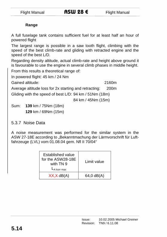
Range A full fuselage tank contains sufficient fuel for at least half an hour of powered flight The largest range is possible in a saw tooth flight, climbing with the speed of the best climb-rate and gliding with retracted engine and the speed of the best L/D. Regarding density altitude, actual climb-rate and height above ground it is favourable to use the engine in several climb phases in middle height. From this results a theoretical range of: In powered flight: 45 km / 24 Nm Gained altitude: 2160m Average altitude loss for 2x starting and retracting: 200m Gliding with the speed of best L/D: 94 km / 51Nm (18m) 84 km / 45Nm (15m) Sum: 139 km / 75Nm (18m) 129 km / 69Nm (15m) 5.3.7 Noise Data A noise measurement was performed for the similar system in the ASW 27-18E according to „Bekanntmachung der Lärmvorschrift für Luft-fahrzeuge (LVL) vom 01.08.04 gem. Nfl II 70/04“
Established value for the ASW28-18E
with TN 9 LA korr max
Limit value
XX,X dB(A) 64,0 dB(A)

Flight Manual ASW 28-18 E Flight Manual
Issue: 10.02.2005 Michael Greiner Revision: TN9 / 6.11.08
7.17
Power-Plant Main Switch
A 12A circuit breaker serves as main switch. It is located in the instru-ment panel and labelled “Engine Master switch”. It is switched on by pressing the button, and opened with the red knob.
Power-Plant Instrument
The power-plant instrument of the ASW 28-18E fits in a Ø52mm hous-ing in the instrument panel. It has several governance, monitoring and display functions: 1 It controls the electric jackshaft, when the power-plant lever
is placed in the corresponding position. 2 It influences the ignition. Independently from the power-
plant lever it shuts down the ignition, whenever the engine is not completely extended or the rotational speed exceeds the maximum permissible RPM.
3 It displays the state of the power-plant (retracted or ex-tended, rotational speed, fuel quantity, voltage, elapsed time) and supplies warnings in case of limit exceedance or maloperation.
4 It checks the fuel quantity in the fuselage tank and eventu-ally opens the valve between the wing and fuselage tanks (optionally).
For few seconds after engaging the instruments switches all LEDs and the alarm sound on. IMPORTANT NOTE: A continuous alarms (=Caution) resound if limits
are exceeded or undershot (rotational speed, fuel quan-tity, voltage). The alarm because of low fuel quantity can be acknowledged with button (9), quieting it for 4 min. Pulsing alarms (=Important notes) resound in connection with indications on the LCD display.
Flight Manual ASW 28 E Flight Manual
Issue: 10.02.2005 Michael Greiner Revision:
7.18
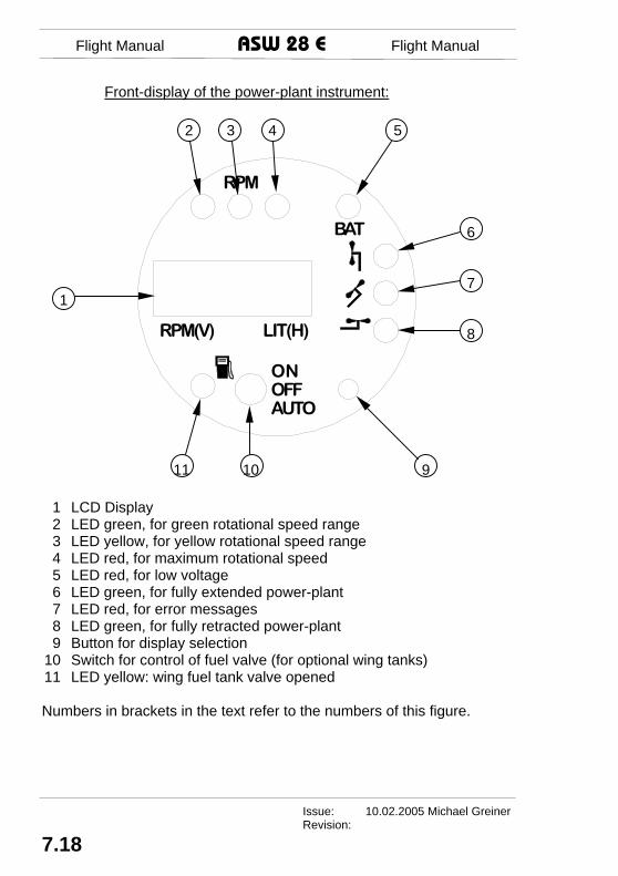
Front-display of the power-plant instrument:
BAT
RPM
ONOFFAUTO
RPM(V) LIT(H)
1 LCD Display 2 LED green, for green rotational speed range 3 LED yellow, for yellow rotational speed range 4 LED red, for maximum rotational speed 5 LED red, for low voltage 6 LED green, for fully extended power-plant 7 LED red, for error messages 8 LED green, for fully retracted power-plant 9 Button for display selection
10 Switch for control of fuel valve (for optional wing tanks) 11 LED yellow: wing fuel tank valve opened Numbers in brackets in the text refer to the numbers of this figure.
2 3 4 5 6 71 8 11 10 9

Flight Manual ASW 28-18 E Flight Manual
Issue: 10.02.2005 Michael Greiner Revision:
7.19
Control of electric jackscrew
To extend or retract the power-plant, bring the power-plant lever in the corresponding position (see section 4.5.3).
The green light (6) indicates, that the power-plant is fully extended. The green light (8) indicates the power-plant to be completely retracted.
To slow down the movement of the power-plant near its end position, the power-plant instrument repeatedly interrupts the current supply of the jackscrew. If the power-plant is started from a half extended posi-tion, the movement is pulsing from the beginning. If the power-plant is not fully extended, but the power-plant lever is mo-ved beyond position „EXTEND“, the red light (7) flashes, a pulsing alarm tone sounds and the LCD (1) displays the word „EXTRACT“.
If the power-plant lever does not receive a signal from the end-switch for an unusual long time, it stops the jackscrew. The red light (7) flashes, a pulsing alarm tone sounds and the LCD (1) displays „SWITCH R“ re-spectively „SWITCH E“. The possible fault may be either a faulty end-switch, a jammed engine mount or low voltage. The alarm can be ac-knowledged with button (9), restarting the jackscrew again. As long as there is no signal from the end-switch saying “fully extended”, the igni-tion is blocked. (see section 3.7)
Influence on ignition
The power-plant instrument features own relays to block ignition inde-pendently from the pilot’s ignition switch. It blocks ignition as long as the power-plant is not fully extended and as soon as the maximum rota-tional speed is exceeded.
IMPORTANT NOTE: If the current supply of the power-plant instrument is interrupted, it cannot block the ignition.
Control of the electric fuel pump
To support the pneumatic fuel pump, the power-plant instrument acti-vates the electric fuel pump during windmilling.

Flight Manual ASW 28 E Flight Manual
Issue: 10.02.2005 Michael Greiner Revision: TN9 / 6.11.08
7.20
Display of power-plant status
Section 2.5 describes the modes of the LCD-Display (1).
A sensor at the magnetic flywheel measures the rotational speed. It is displayed in the permanent display at the left side. When the engine runs with its target speed the green LED (2) lights. The yellow LED (3) warns of approaching the maximum RPM. When reaching the maximum rotational speed, the ignition is switched off and the red LED (4) beams.
The red LED (5) lights, whenever the battery voltage falls below 11,5V.
Fuel monitoring
A sensor monitores the content of the fuselage tank. The display is cali-brated for flight attitude. Therefore, on ground, it deviates from the ac-tual fuel quantity. Also in flight the angle of attack varies, thus a calibra-tion more accurate than for half a liter (0.13 US Gal.) is not reasonable. The scale behind the backrest is calibrated for ground attitude.
When the fuel quantity of the fuselage tank sinks below 2,5Ltrs (0.66 US Gal) for over 5s, a alarm resounds and the display starts to blink.
Switch (10) controlls the fuel system, if flexible wing tanks are installed (optionally). The upper position “ON” opens the solenoid valve of the flexible wing tanks, simultaneously the yellow LED (11) lights up. The solenoid valves stay opened even if the fuselage tank is full. This posi-tion is intended to completely empty the wing tanks. The lower position “AUTO” triggers the automatic refill of the fuselage tank. When the fuel quantity in the fuselage tank sinks below 3,5Ltrs (0.92 US Gal), the so-lenoid valve opens automatically, LED (11) lights up and fuel can flow from the wings into the fuselage tank. As soon as the fuselage tank is full, the solenoid valve is closed and LED (11) extinguishes. Thereby it is excluded that fuel gets lost through the ventilation. See section 7.13 for handling of the fuel system.

Flight Manual ASW 28-18 E Flight Manual
Issue: 10.02.2005 Michael Greiner Revision:
7.21
IMPORTANT NOTE: The solenoid valve is a bistable one, that needs only short impulses to toggle. To ensure the correct posi-tion of the valve, it gets a short pulse regularly. On ground this can be heard as a quiet click. This is no mal-function.
The calibration of the fuel sensor was done with fuel-oil mixture based on AVGAS 100LL. Mixtures based on other fuel qualities may lead to deviating indications. Thereby the deviation is largest with full tank and zero with empty tank.
The power-plant instrument can be set to other qualities. The fuel tank must be filled with at least 6Ltrs (1.58 US Gall) and the power-plant re-tracted. Press button (9) four times until „Calibr.?“ appears at the display. Then keep button (9) pressed for five seconds to perform the calibration.
After the calibration, the power-plant instrument assumes that the signal from the fuel sensor corresponds a full tank. With a full tank, the differ-ence between flight and ground attitude is small.

Flight Manual ASW 28 E Flight Manual
Issue: 10.02.2005 Michael Greiner Revision: TN9 / 6.11.08
7.22
Display- and warning-ranges of the power-plant instrument:
Type Display-range Optical Acoustic
Rotational speed 400 – 9990 rpm See
section 2.5
> 5400 rpmpermanent
alarm
Battery voltage 10 – 15V < 11,5V
LED (5) blinks
< 11,5V permanent
alarm
Fuel quantity 0 – 6,3Ltrs < 2,5Ltrs LCD blinks
< 2,5Ltrs permanent
alarm
Valve of wing tanks
If switch (10) is tog-gled to “AUTO“, the valve opens below
3,5Ltrs in the fuselage tank and closes at
6Ltrs
LED (11) lights, when valve open
Elapsed time counter
Counts above 2000 rpm
Electric fuel pump
Runs, when the en-gine is extended, rota-tional speed is below 4200 rpm and ignition
is on
Prop brake open and engine not fully extended
LED (7) blinks Pulsed alarm
Running time of jackscrew > 20s
LED (7) blinks> 20s
pulsed alarm
Rear-view mirror
A rear-view mirror in the cockpit is necessary to check the correct posi-tion of the propeller before retracting the power-plant.

Flight Manual ASW 28-18 E Flight Manual
Issue: 10.02.2005 Michael Greiner Revision:
7.23
7.13 Fuel System Overview of the fuel system:
baggage compartment floor
vent
ilatio
n
win
g ta
nk fu
el li
ne
wing tank
solenoidvalve
electricfuel pump
filter
drain valve
win
g ta
nk v
entil
atio
n
Configuration withone wing tank:
Installation on left side!
baggage compartment floor
fuel cock
firewall
impuls-line to the crankcase
to thecarburettors
pneumaticfuel pump
firewall
fuselage tank 6 ltrs
electricfuel pump
refuelling coupling
A B
C C
A
Bw
ithou
t win
g ta
nks
with wing tank(s)
with wing tank(s)
Flight Manual ASW 28 E Flight Manual
Issue: 10.02.2005 Michael Greiner Revision: TN9 / 6.11.08
7.24
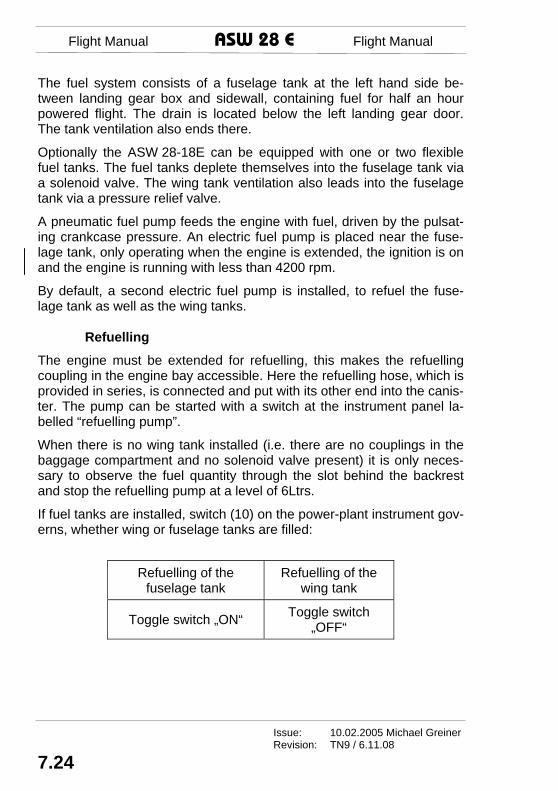
The fuel system consists of a fuselage tank at the left hand side be-tween landing gear box and sidewall, containing fuel for half an hour powered flight. The drain is located below the left landing gear door. The tank ventilation also ends there. Optionally the ASW 28-18E can be equipped with one or two flexible fuel tanks. The fuel tanks deplete themselves into the fuselage tank via a solenoid valve. The wing tank ventilation also leads into the fuselage tank via a pressure relief valve. A pneumatic fuel pump feeds the engine with fuel, driven by the pulsat-ing crankcase pressure. An electric fuel pump is placed near the fuse-lage tank, only operating when the engine is extended, the ignition is on and the engine is running with less than 4200 rpm. By default, a second electric fuel pump is installed, to refuel the fuse-lage tank as well as the wing tanks.
Refuelling
The engine must be extended for refuelling, this makes the refuelling coupling in the engine bay accessible. Here the refuelling hose, which is provided in series, is connected and put with its other end into the canis-ter. The pump can be started with a switch at the instrument panel la-belled “refuelling pump”. When there is no wing tank installed (i.e. there are no couplings in the baggage compartment and no solenoid valve present) it is only neces-sary to observe the fuel quantity through the slot behind the backrest and stop the refuelling pump at a level of 6Ltrs. If fuel tanks are installed, switch (10) on the power-plant instrument gov-erns, whether wing or fuselage tanks are filled:
Refuelling of the fuselage tank
Refuelling of the wing tank
Toggle switch „ON“ Toggle switch „OFF“

Maintenance Manual ASW 28-18 E Maintenance Manual
Issue: 10.02.2005 M.Greiner /KR Revision:
1.5
Fuselage Length 6,585 m (21,6 ft)Height at T-tail incl. tail wheel 1,3 m (4,27 ft)Cockpit width (inside) 0,64 m (2,1 ft)Cockpit height 0,8 m (2,62 ft) Vertical Tail Height above tail boom top edge 1,2 m (3,94 ft)Surface area 1,0 m² (10.76 ft²)Airfoil Section DU 86-131/30 Rudder Surface area 0,3 m² ( 3.23 ft²) Horizontal Tail Span 2,85 m (9,35 ft)Surface area 1,0 m² Aspect ratio 8,22 Airfoil Section DU 92-131/25 Elevator Surface area 0,22 m² Airbrake Blades (Schempp-Hirth-type, top surface only) Length 1,10 m ( 3,61ft)Surface area (both together) 0,36 m² ( 3.88 ft²)Max. Height above wing top surface 0,165 m (0,54 ft) Aileron Span 3,0 m (9,84 ft)Surface area (each) 0,267 m² ( 2.87 ft²)

Maintenance Manual ASW 28-18 E Maintenance Manual
Issue: 10.02.2005 M.Greiner /KR Revision: TN9 / 6.11.08
1.6
Masses (Weights) Span 18 m 15 m Empty mass approx. glider 283 kg 622,6 lbs 270 kg 594 lbs self-sustaining powered sailplane 322 kg 708,4 lbs 309 kg 679,8 lbs
Mass of non-lifting parts max. 285 kg 627 lbs Cockpit Load max. 124 kg 272,8 lbs Pilot Seat Load max. 115 kg 253 lbs Loading of baggage compartment max. 12 kg 26,4 lbs
All-up mass with water ballast max. 575 kg 1265 lbs 525 kg 1155 lbs without water ballast max. 462 kg 1016,4 lbs 450 kg 999 lbs
Max Wing loading approx. 48 kg/m² 9,83 lbs/ft² 50 kg/m² 10.2 lbs/ft²Min Wing loading approx. glider 29 kg/m² 5,94 lbs/ft² 32 kg/m² 6,55 lbs/ft² self-sustaining powered sailplane 33 kg/m² 6,76 lbs/ft² 36 kg/m² 6,76 lbs/ft²
Trim ballast (battery) in the fin max. 6 kg 13,2 lbs Trim ballast in the water tank in the fin max. 5 kg 11 lbs See also Flight Manual section 2! Authoritative information about empty mass and useful load are docu-mented in the weighing record of the A-record or in the mass and bal-ance form in chapter 6.2 of the flight manual. Power Plant Engine Manufacturer SOLO Kleinmotoren GmbH Engine SOLO 2350 Continuous Power 24 PS / 18 kW max. permissible Continuous Speed 5400 RPM max. Cylinder Head Temperature 275°C Fuel 2-stroke mixture with AVGAS 100LL or Super Petrol unleaded min. 95 ROZ Lubrication Lubrication mixture and 2-stroke-oil according to Flight Manual, section 2.4 Propeller Manufacturer Alexander Schleicher GmbH & Co. Propeller AS2F1-3/L100-56-N2

Maintenance Manual ASW 28-18 E Maintenance Manual
Issue: 10.02.2005 M.Greiner /KR Revision: TN9 / 6.11.08
4.5
Oxygen Installation Oxygen equipment must be approved und must be free from hazard (take care of fuel, oil and grease!), especially in crash landings. There must be means available in flight to determine the quantity of oxygen in each source of supply and whether oxygen is being delivered to the dis-pensing equipment. For oxygen systems fitted, the relevant section of the appertaining In-spection Release Certificate states the overhaul time limit. Over and be-yond this, the oxygen bottles may have to be re-inspected by a technical inspection institute at other intervals in accordance with pressure vessel regulations existing in the country of operation. Safety Harness For the safety harness installed the life time limitation according to the appropriate maintenance instructions given by the harness manufac-turer apply. Engine For the engine SOLO 2350 the maintenance instructions of the engine manual apply. Maintenance intervals are specified there. Latter informa-tion may be published in Technical Notes, if applicable. Propeller For the propeller AS2F1-3 the maintenance instructions of the propeller manual apply. Maintenance intervals are specified there. Latter informa-tion may be published in Technical Notes, if applicable.

Maintenance Manual ASW 28-18 E Maintenance Manual
Issue: 10.02.2005 M.Greiner /KR Revision: TN9 / 6.11.08
4.6
Only applicable to U.S. registered gliders! 4.3 Airworthiness Limitations This Airworthiness Limitations Section is FAA approved for U.S. regis-tered gliders and specifies maintenance required under 43.16 and 91.403 of the Federal Aviation Regulations unless an alternative pro-gram has been FAA approved. The following components are time limited or limited by number of launches: 1. The FRP-structure (FRP = Fibre Reinforced Plastic) is limited to
12000 service hours. Extension seems to be possible in the future. Special inspections starting at 3000 service hours have to be per-formed. For details, see chapter 4.1 of this manual.
2. The O-rings of the water ballast valves have a time limit of 5 years.
3. The brake line hose has a time limit of 6 years, which can be ex-tended on a 100-hour inspection basis.
4. For the TOST tow releases see the instructions given by TOST with every individual tow release.
5. For oxygen supply systems regard the time limit of the individual pressure vessel as well as the individual overhaul time limits of the components.
6. For the safety harness system time limit, see the instructions given by the harness manufacturer with the individual harness system.
7. For the engine refer to the inspections defined by the engine manu-facturer.
8. The propeller is to be inspected according to the propeller manual.
For details applying to 2. through 8. see chapter 4.2 of this manual.

Maintenance Manual ASW 28-18 E Maintenance Manual
Issue: 10.02.2005 M.Greiner /RBG Revision: TN9 / 6.11.08
12.9
12.4 List of Maintenance Documents for Fitted Equipment a) Operating Manual for Tow Release Coupling Series "Europa G 88"
Safety Tow Release, in the latest valid issue; or Operating Manual for the Tow Release Coupling, Series: Safety Tow Release "Europa G 72" and Safety Tow Release "Europa G 73", in the latest valid is-sue. Operating Manual for Tow Release Coupling, Series Nose Tow Re-lease Hook "E 85", in the latest valid issue. Or Operating Manual for Tow Release Coupling, Series Nose Tow Release Hook "E 72" and "E 75", in the latest valid issue.
b) WHEEL and BRAKE ASSEMBLIES CATALOGUE Component Maintenance Manual, Appendix A, Fits and Clearances A-1. Brake Lining Wear Limits A-2. Brake Disc Minimum Thickness issued by Parker Hannifin Corporation, Avon, Ohio.
c) Engine Manual SOLO 2350, in its currently valid edition. Instruction for special inspection of engine type SOLO 2350 after
5 years service life, in its currently valid edition. d) Operating and Maintenance Manual for the propeller AS2F1, series
AS2F1-3, in the latest valid edition. Technical Note 2 for AS Propeller, in the latest valid edition, inform-
ing about service life limitations
Maintenance Manual ASW 28-18 E Maintenance Manual
Issue: 10.02.2005 M.Greiner /RBG Revision:
12.10
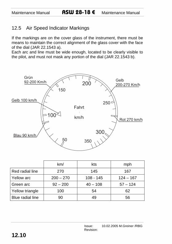
12.5 Air Speed Indicator Markings If the markings are on the cover glass of the instrument, there must be means to maintain the correct alignment of the glass cover with the face of the dial (JAR 22.1543 a). Each arc and line must be wide enough, located to be clearly visible to the pilot, and must not mask any portion of the dial (JAR 22.1543 b).
� � � � �
� � � �
�
�
� �
� �
� � � �
� � � � � � � � �� � � �
� � � � � � � � �
� � � � � � � � � � �
� � � � � � � � � �
� � � � � � � � � � �
km/ kts mph
Red radial line 270 145 167 Yellow arc 200 – 270 108 - 145 124 – 167 Green arc 92 – 200 40 – 108 57 – 124 Yellow triangle 100 54 62 Blue radial line 90 49 56