Embed Size (px)
Citation preview
GBAS CAT II/III
Operational Validation
Input for Business
Aircraft
Flight Tests and Simulations
Executive Summary
<3 March 2015>
Edition 00.01.00
SESAR 09.12.
In order to support GBAS CAT II/III (GAST D) validation, an extensive flight test campaign was carried out in Sep/Oct 2013 with Honeywell flight test aircraft Dassault Falcon 900EX – Phase 1 and recently, Phase 2, was carried out in Jun/Jul 2014. This paper focuses on Phase 2 and it is an executive summary of D27 Business Aircraft Simulation Tools Development and Upgrade delivered by project 09.12 “ GBAS Cat II/III”. This document describes the data collection campaign, together with details on experimental aircraft used, test setup as well as flight plan. Moreover, it focuses on data analyses, with respect to overall performance, and specific monitors’ performance. Then results on NSE model validation and generic business aircraft Autoland feasibility simulations are discussed. The conclusions from the presented results are drawn in the last section.
GBAS CAT II/III Operational Validation Input for Business Aircraft
00.01.00
1 of 43
Authoring & Approval
Prepared By
Name Position / Title Date
Jolana Dvorska /Honeywell Technical Manager / Principal Investigator
03-04-2015
Ladislav Podivin /Honeywell Scientist R&D 03-04-2015
Lenka Zaviralova /Honeywell Scientist R&D 03-04-2015
Martin Musil /Honeywell Scientist R&D 03-04-2015
Michal Kren /Honeywell Scientist R&D 03-04-2015
Reviewed By
Name Position / Title Date
Jolana Dvorska /Honeywell Technical Manager / Principal Investigator
03-04-2015
Martina Stehlikova/ Honeywell Contribution Manager 03-04-2015
Stephane Marche/ Honeywell Chief Architect 03-04-2015
Mats Brenner/ Honeywell Staff Scientist 03-04-2015
Brian Schipper/ Honeywell Staff Scientist 03-04-2015
Approved By
Jolana Dvorska /Honeywell Technical Manager 22/03/2016 (template change only)
Martina Stehlikova/ Honeywell Contribution Manager 22/03/2016 (template change only)
Stephane Marche/ Honeywell Chief Architect 03-04-2015
Dietmar Kleinitz/ Airbus 9.12 Project Manager 03-04-2015 (approval of original D27)
Document History
Version Effective Date Page(s) Affected
Reason for and Extent of Change(s)
00.01.000 02 May 2016 All New Document; based on ION ITM 2015 paper: Dvorska, Jolana, Podivin, Ladislav, Zaviralova, Lenka, Musil, Martin, Kren, Michal, "GBAS CAT II/III Operational Validation Input for Business Aircraft – Flight Tests and Simulations," Proceedings of the ION 2015 Pacific PNT Meeting, Honolulu, Hawaii, April 2015, pp. 779-798.
GBAS CAT II/III Operational Validation Input for Business Aircraft
00.01.00
2 of 43
Table of Contents 1 INTRODUCTION .............................................................................................................................................. 3
1.1 PURPOSE ................................................................................................................................................ 4 1.2 ACRONYMS AND TERMINOLOGY ..................................................................................................................... 4
1.2.1 GENERAL ......................................................................................................................................... 4
2 FLIGHT TEST CAMPAIGN ................................................................................................................................ 5
3 FLIGHT TEST DATA ANALYSIS – PERFORMANCE PHASE 2 ............................................................................. 8
3.1 NAVIGATION SYSTEM ERROR – PHASE 2 .......................................................................................................... 8 3.2 NSE VS XPL .............................................................................................................................................. 11 3.3 TOTAL SYSTEM ERROR – PHASE 2 ................................................................................................................. 12 3.4 AIRBORNE MULTIPATH ANALYSIS .................................................................................................................. 15
4 FLIGHT TEST DATA ANALYSIS – PHASE 1 VS PHASE 2 PERFORMANCES ..................................................... 17
5 DATA ANALYSIS – MONITORS ..................................................................................................................... 19
5.1 DUAL SOLUTION IONOSPHERIC GRADIENT MONITOR – PHASE 2 POST PROCESSED ................................................. 20 5.2 CODE CARRIER DIVERGENCE – PHASE 2 ......................................................................................................... 21 5.3 FAULT DETECTION – PHASE 2 POST PROCESSED .............................................................................................. 22 5.4 LOSS OF APPROACH GUIDANCE – PHASE 2 ..................................................................................................... 23 5.5 VDB AUTHENTICATION MONITOR ................................................................................................................ 24
6 PERFORMANCE SUMMARY ......................................................................................................................... 26
6.1 APPROACH SERVICE TYPE DOWNGRADE ......................................................................................................... 26 6.2 SATELLITE EXCLUSIONS................................................................................................................................ 26 6.3 DEVIATIONS INVALIDATION .......................................................................................................................... 27 6.4 NSE MODEL VALIDATION ...................................................................................................................... 27 6.5 JLISS NSE MODEL DESCRIPTION .................................................................................................................. 27 6.6 NSE MODELS COMPARISON ........................................................................................................................ 29 6.7 MEASURED AND SIMULATED NSE COMPARISON ............................................................................................. 30
7 AUTOLAND FEASIBILITY SIMULATIONS ....................................................................................................... 33
7.1 NOMINAL CASE ......................................................................................................................................... 35 7.2 LIMIT CASE ............................................................................................................................................... 37 7.3 MALFUNCTION CASE .................................................................................................................................. 37
8 CONCLUSIONS ......................................................................................................................................... 39
8.1 CONCLUSIONS AND RECOMMENDATIONS SUMMARY ........................................................................... 40
9 ACKNOWLEDGMENTS ........................................................................................................................... 42
10 REFERENCES ....................................................................................................................................... 43
GBAS CAT II/III Operational Validation Input for Business Aircraft
00.01.00
3 of 43
1 Introduction In order to support GBAS CAT II/III (GAST D) validation, an extensive flight test campaign was carried out in Sep/Oct 2013 with Honeywell flight test aircraft Dassault Falcon 900EX – Phase 1 and recently, Phase 2, was carried out in Jun/Jul 2014. This paper focuses on Phase 2.
The aircraft was equipped with a prototype GAST D avionics receiver that was coupled with the autopilot of the CAT II capable aircraft. Testing in Phase 2 was performed on five different airports, with five different ground stations from three manufacturers, in the US and in Europe. The ground and airborne equipment was at its final prototype functionality.
Since flight tests typically only show nominal performance of the overall system and cannot comprise corner cases, Monte-Carlo approach and landing simulations covering nominal, limit and malfunction cases must be performed to show the overall system compliance with the Autoland requirements.
In order to collect all the data needed with respect to the objectives, the experimental aircraft was equipped with an airborne receiver prototype with GBAS GAST D final capability, a Novatel survey grade dual-frequency receiver (SPAN) for truth measurements, a Telerad RE9009 VHF receiver and Multi-constellation multi-frequency (MC/MF) receiver prototype.
The three GPS/GNSS receivers were all connected to the same GNSS dual frequency antenna. VHF Data Broadcast (VDB) for the three relevant receivers (in this case the GBAS prototype, Telerad and MC/MF) are connected to the same VHF NAV/LOC antenna situated at the top of the vertical fin of the experimental aircraft. The ARINC 429 outputs of the GBAS prototype are coupled with the autopilot.
The Phase 2 flight plan covered a total of 95 approaches to collect sufficient amount of data. Phase 2 focused on 9 scenarios, including data collection for multipath performance testing, interoperability validation, airborne regressions to CAT I approach (GAST C) and non-regression GAST C approaches.
Detailed analysis of results was performed, including navigation system error evaluation, total system error as well as performance of the required monitors and their impact on availability of the solution.
Navigation sensor error and total system error were analyzed and are showing good performance. Analysis with respect to the airborne multipath was performed also for Phase 2 and results shown are confirming expectations - multipath performance on a larger business aircraft not quite conforming with the RTCA multipath model, but in line with the multipath plus noise requirements leading to reasonable sigma error estimates.
Monitor performance was analyzed and was conforming to expectations during nominal conditions. Downgrades to lower approach service type was observed during the testing caused by Fault Detection during approach and taxi phases; further analysis led to the conclusion that improved specification of the monitor is required. This update is currently under development. Dual solution ionospheric gradient monitor caused downgrades only while stationary, due to increased levels of ground multipath as well as reflections off nearby buildings, which does not affect the GAST D operation.
Observed satellite exclusions were caused by the Code-Carrier Divergence monitor, which is very much in line with expectations. The exclusion of satellites exceeding the filter threshold never caused downgrade or loss of availability.
Corrections and finalization of both ground and airborne parts in Phase 2 resulted in better navigation performance than in Phase 1. The overall GBAS Navigation system performance was improved compared to Sep/Oct 2013. The improved NSE can be explained by improvements in both airborne and ground systems, as well as by more data collected.
Overall, the flight tests were very successful and support the concept validation.
With respect to the simulations, a Honeywell legacy simulation tool consisting of models of generic business aircraft with receiver model upgraded to GAST D capability, ground station model including reference receivers, constellation model and error models such as ionospheric, tropospheric, multipath and noise was used for the Monte-Carlo simulations based on requirements from regulatory bodies.
GBAS CAT II/III Operational Validation Input for Business Aircraft
00.01.00
4 of 43
It was confirmed that the navigation sensor error observed during the flight tests is within the used model which is consistent with AWOHARC GBAS noise model that may be used to show compliance with approach and landing requirements.
Overall 18 scenarios (with close to 300,000 simulation runs), including different generic A/C and autopilot models (FTE), almanacs, NSE model and airport set, were simulated during feasibility analysis and the results were statistically analyzed to show if the compliance with landing requirements defined by CS-AWO is met. Nominal and limit cases performed within expectations and complied with requirements. Since the autoland simulations use generic autopilot assumptions, the result shows the theoretical capability of business aircraft with the assumed touchdown distribution meeting the landing requirements when using GBAS GAST D. The feasibility generic simulations pointed to short steep ramp faults close to ca 200ft within malfunction case which in a few cases resulted in shorter approaches (but still within the runway). Although a more robust A/C control system behavior with an appropriate filtering or control system limitations than in the presented generic model is expected, it is highly recommended that this possible threat is well reviewed and confirmed by airframe manufacturers that it is covered.
1.1 Purpose In order to support GBAS GAST D (CAT II/III) validation, an extensive flight test campaign was carried out in Sep/Oct 2013 with Honeywell flight test aircraft Dassault Falcon 900EX – Phase 12 and recently, Phase 2, was carried out in Jun/Jul 2014. A total of 150 approaches were flown over both campaigns. The aircraft was equipped with a Honeywell prototype GAST D avionics receiver that was coupled with the autopilot of the CAT II capable aircraft. Testing was performed on six different airports with seven different ground stations from different manufacturers (Honeywell, Indra, and Thales and the FAA) for both phases in the US and in Europe with support of ANSPs – Air Navigation Service Providers (German DFS, French DSNA, US FAA). The ground and airborne equipment was at its final prototype functionality. The objectives of the second flight tests campaign, data collection and simulations in this paper are focused on:
Verify performance in operational environment for business aircraft with ground stations in Phase 2, with focus on navigation system error evaluation, total system error, as well as performance of the required monitors and their impact on availability of the solution.
Compare results with Phase 1.
Validate Honeywell NSE range domain model used in Autoland simulations.
Perform feasibility study on approach and landing simulations with generic business aircraft model. The following sections will describe the data collection campaign, together with details on experimental aircraft used, test setup as well as flight plan. The next section focuses on data analyses, with respect to overall performance, and specific monitors’ performance. Then results on NSE model validation and generic business aircraft Autoland feasibility simulations are discussed. The conclusions from the presented results are drawn in the last section.
1.2 Acronyms and Terminology
1.2.1 GENERAL
ATM: Air Traffic Management
E-ATMS: European Air Traffic Management System
SESAR: Single European Sky ATM Research Programme
SJU: SESAR Joint Undertaking (Agency of the European Commission)
SJU Work Programme: addresses all activities of the SESAR Joint Undertaking Agency.
SESAR Programme: defines the Research and Development activities and Projects for the SJU.
GBAS CAT II/III Operational Validation Input for Business Aircraft
00.01.00
5 of 43
2 Flight Test Campaign In order to collect data needed for the GBAS GAST D interoperability and validation testing, an extensive flight test campaign was executed.
After Phase 1 flight tests (for Phase 1 results analysis see 2), the airborne receiver prototype SW was updated with the remaining requirements and updates based on Phase 1 results. This was followed by static and dynamic testing on an airport. The next step was the prototype integration into aircraft test bench to ensure correct integration design, and verify all the outputs during simulated flight on the target airports. Initial flight tests for Phase 2 to verify the integration and functionality were carried out in June 2014 with Houston Honeywell certified ground station, and the Honeywell ground station in Atlantic City. The results from this initial testing of Phase 2 are included in this paper.
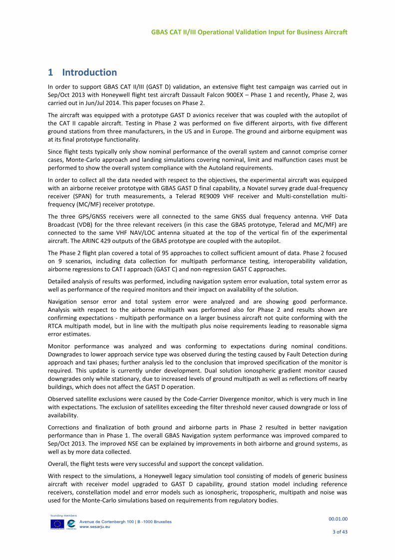
The same experimental aircraft as for Phase 1 (Figure 1) was also used for Phase 2 testing.
Figure 1: Honeywell experimental test aircraft F900
In order to support the objectives of the testing and for on board data collection, the aircraft installation includes a VIDL/G airborne receiver prototype with GBAS GAST D final prototype capability, a Novatel survey grade dual-frequency receiver (SPAN) for truth measurements, a Telerad RE9009 VHF receiver and a MCMF prototype (instead of an INR airborne receiver prototype included on a FAA test palette for interoperability testing and additional data collection in Phase 1). With that exception the aircraft installation test setup remained the same.
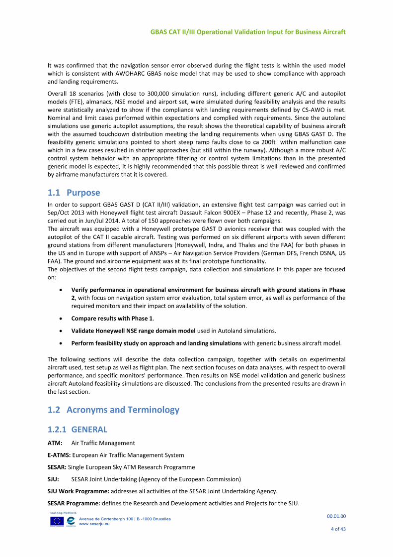
Figure 2 shows the aircraft installation setup. The three GPS/GNSS receivers (VIDL/G, Novatel and MC/MF) are all connected to the same GNSS dual frequency antenna (different location then in Phase 1, now closer to the tail). VDB for the three relevant receivers (in this case the VIDL/G, Telerad and MC/MF) are connected to the same VHF NAV/LOC antenna situated at the top of the vertical fin of the experimental aircraft. The ARINC 429 outputs of the VIDL/G prototype are coupled with the autopilot. The prototype was tuned to the correct channel using a tuning head.
The RS232 data output, as well as ARINC 429 outputs from the tested VIDL/G prototype receiver were recorded using a laptop. A Honeywell Test Interface Unit (TIU) used ARINC 429 labels in order to provide GBAS deviations, as well as approach ID and supported level of service (GAST C / GAST D) to the experimental Display Unit. Required data on the aircraft internal bus (ASCB) were recorded using the TIU for validation purposes. Novatel receiver outputs were also recorded using the TIU in order to support post-processing using data from a ground based Novatel receiver with a surveyed antenna.
RS485 VDB data were recorded from the Telerad receiver to check for excessive CRC errors on the test prototypes, as well as to see if the slots in the broadcasted messages were being filled correctly. Telerad has been updated with a special SW developed on request to enable verification of slot overflows during flight testing for Phase 2.
GBAS CAT II/III Operational Validation Input for Business Aircraft
00.01.00
6 of 43
Serial output data from the MC/MF prototype were recorded using a PC (processing of the data is out of scope of the project and this paper).
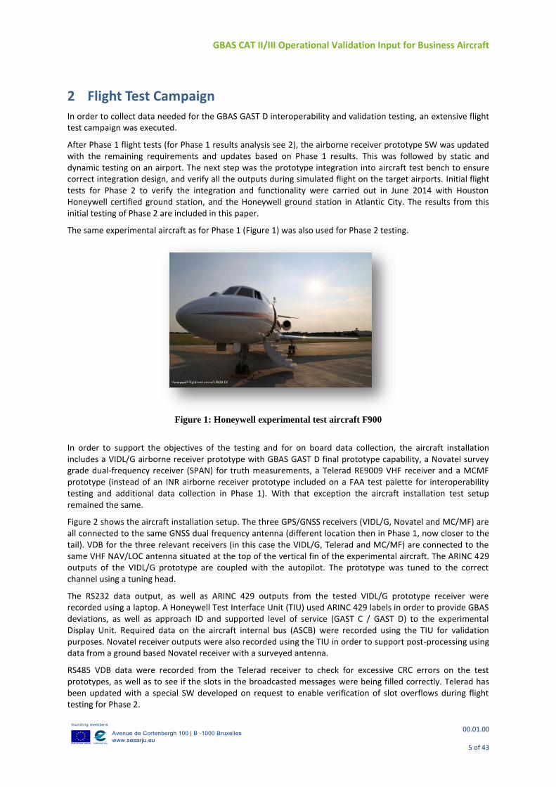
An experimental display and its logic were implemented in the same way as for Phase 1. It was used to enable the pilots as well as flight test crew to easily see the GBAS modes selected and achieved, as well as for visual verification of the status during each test scenario (these were of course post-processed). Figure 3 shows the experimental display during GBAS CAT II/III approach in Atlantic City.
Figure 3: Experimental display – GBAS CAT II/III approach in Atlantic City
During the Phase 2 flight trial campaign, 5 different stations from 3 different manufacturers, both US and European were used. Two were Honeywell GAST C certified stations, one was a Honeywell GAST D experimental station and the rest were one each, Indra and Thales experimental GAST D ground stations.
Table 1 provides a brief overview of systems used in Phases 1 & 2. The focus of this paper is on the business aircraft airborne system, not the ground stations.
Figure 2: Aircraft installation setup focusing on the specific GBAS testing equipment for Phase 2
GBAS CAT II/III Operational Validation Input for Business Aircraft
00.01.00
7 of 43
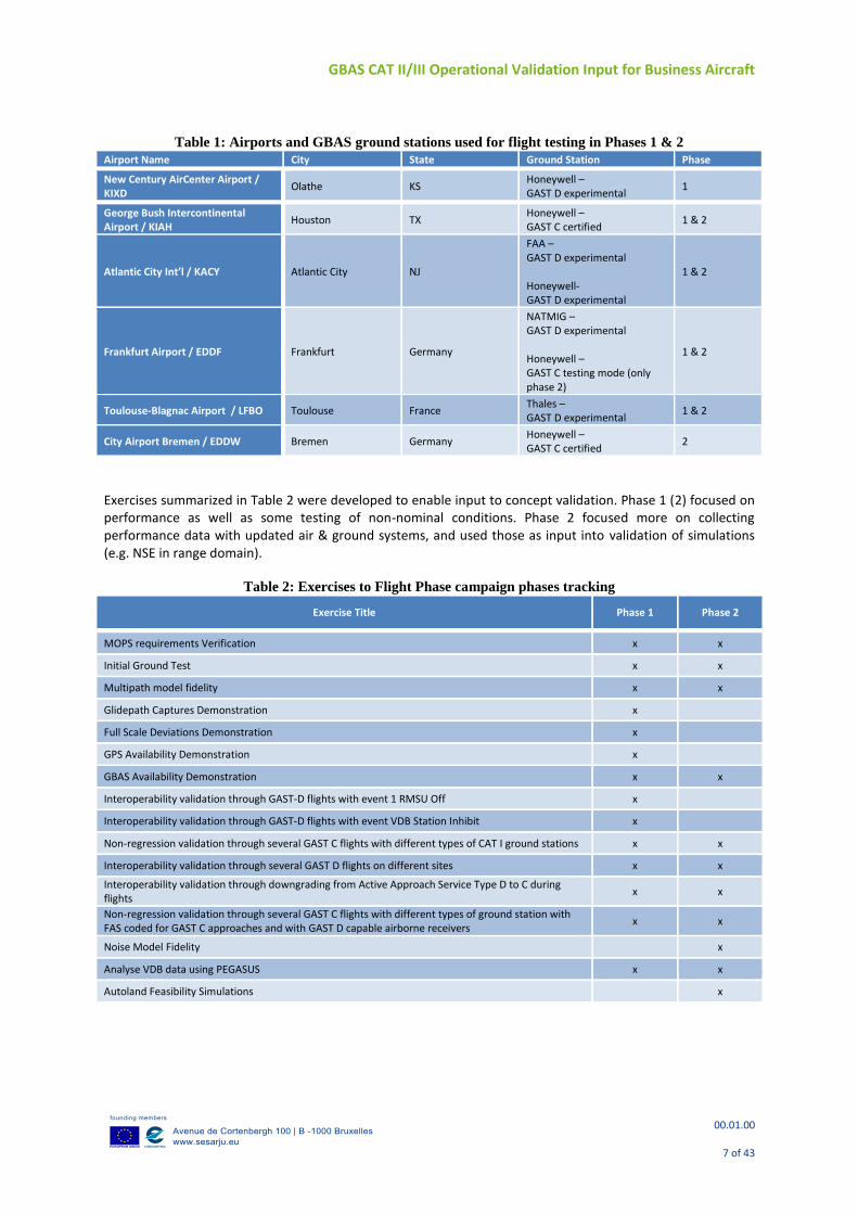
Table 1: Airports and GBAS ground stations used for flight testing in Phases 1 & 2
Airport Name City State Ground Station Phase
New Century AirCenter Airport / KIXD
Olathe KS Honeywell – GAST D experimental
1
George Bush Intercontinental Airport / KIAH
Houston TX Honeywell – GAST C certified
1 & 2
Atlantic City Int’l / KACY Atlantic City NJ
FAA – GAST D experimental Honeywell- GAST D experimental
1 & 2
Frankfurt Airport / EDDF Frankfurt Germany
NATMIG – GAST D experimental Honeywell – GAST C testing mode (only phase 2)
1 & 2
Toulouse-Blagnac Airport / LFBO Toulouse France Thales – GAST D experimental
1 & 2
City Airport Bremen / EDDW Bremen Germany Honeywell – GAST C certified
2
Exercises summarized in Table 2 were developed to enable input to concept validation. Phase 1 (2) focused on performance as well as some testing of non-nominal conditions. Phase 2 focused more on collecting performance data with updated air & ground systems, and used those as input into validation of simulations (e.g. NSE in range domain).
Table 2: Exercises to Flight Phase campaign phases tracking
Exercise Title Phase 1 Phase 2
MOPS requirements Verification x x
Initial Ground Test x x
Multipath model fidelity x x
Glidepath Captures Demonstration x
Full Scale Deviations Demonstration x
GPS Availability Demonstration x
GBAS Availability Demonstration x x
Interoperability validation through GAST-D flights with event 1 RMSU Off x
Interoperability validation through GAST-D flights with event VDB Station Inhibit x
Non-regression validation through several GAST C flights with different types of CAT I ground stations x x
Interoperability validation through several GAST D flights on different sites x x
Interoperability validation through downgrading from Active Approach Service Type D to C during flights
x x
Non-regression validation through several GAST C flights with different types of ground station with FAS coded for GAST C approaches and with GAST D capable airborne receivers
x x
Noise Model Fidelity x
Analyse VDB data using PEGASUS x x
Autoland Feasibility Simulations x
GBAS CAT II/III Operational Validation Input for Business Aircraft
00.01.00
8 of 43
3 FLIGHT TEST DATA ANALYSIS – PERFORMANCE PHASE 2 In order to process the collected data, they were segmented into regions of interest, including approach (coupled to autopilot), Precision Approach Region (PAR), taxi, stationary (close to buildings and on runway/taxiway), and other air phases. These are used in the following parts of the paper; approach phase is the one with most focus here.
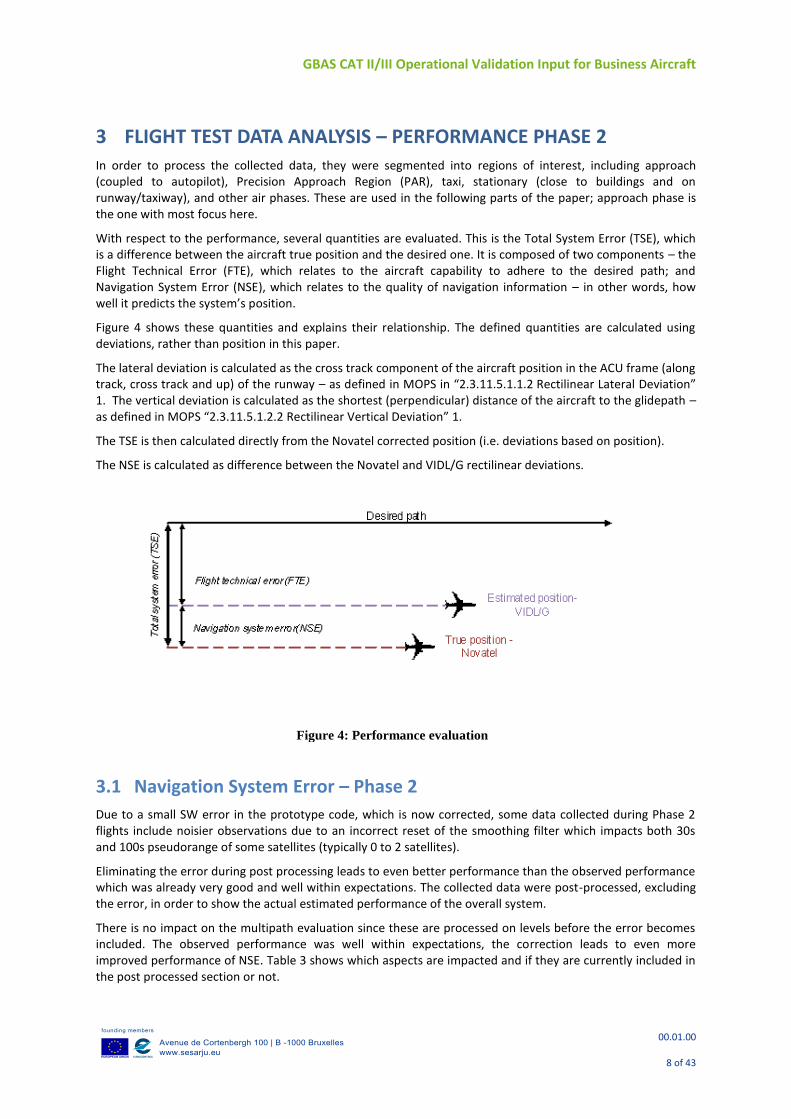
With respect to the performance, several quantities are evaluated. This is the Total System Error (TSE), which is a difference between the aircraft true position and the desired one. It is composed of two components – the Flight Technical Error (FTE), which relates to the aircraft capability to adhere to the desired path; and Navigation System Error (NSE), which relates to the quality of navigation information – in other words, how well it predicts the system’s position.
Figure 4 shows these quantities and explains their relationship. The defined quantities are calculated using deviations, rather than position in this paper.
The lateral deviation is calculated as the cross track component of the aircraft position in the ACU frame (along track, cross track and up) of the runway – as defined in MOPS in “2.3.11.5.1.1.2 Rectilinear Lateral Deviation” 1. The vertical deviation is calculated as the shortest (perpendicular) distance of the aircraft to the glidepath – as defined in MOPS “2.3.11.5.1.2.2 Rectilinear Vertical Deviation” 1.
The TSE is then calculated directly from the Novatel corrected position (i.e. deviations based on position).
The NSE is calculated as difference between the Novatel and VIDL/G rectilinear deviations.
3.1 Navigation System Error – Phase 2
Due to a small SW error in the prototype code, which is now corrected, some data collected during Phase 2 flights include noisier observations due to an incorrect reset of the smoothing filter which impacts both 30s and 100s pseudorange of some satellites (typically 0 to 2 satellites).
Eliminating the error during post processing leads to even better performance than the observed performance which was already very good and well within expectations. The collected data were post-processed, excluding the error, in order to show the actual estimated performance of the overall system.
There is no impact on the multipath evaluation since these are processed on levels before the error becomes included. The observed performance was well within expectations, the correction leads to even more improved performance of NSE. Table 3 shows which aspects are impacted and if they are currently included in the post processed section or not.
Figure 4: Performance evaluation
GBAS CAT II/III Operational Validation Input for Business Aircraft
00.01.00
9 of 43
Table 3: Post-processed performance
Impact Post-processed Results Impact of the correction on Result / Feedback to Concept validation
NSE Yes Results included Better performance (smaller max values)
NSE vs. JLISS Yes Results included Better performance (smaller max values)
NSE vs xPL Yes Not included (not evaluated yet) Better performance expected
Multipath No No impact on results No impact
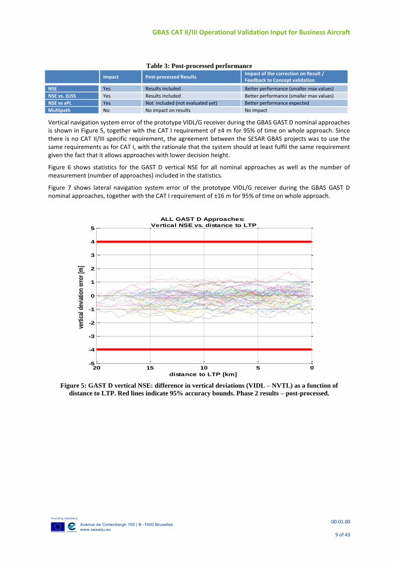
Vertical navigation system error of the prototype VIDL/G receiver during the GBAS GAST D nominal approaches is shown in Figure 5, together with the CAT I requirement of ±4 m for 95% of time on whole approach. Since there is no CAT II/III specific requirement, the agreement between the SESAR GBAS projects was to use the same requirements as for CAT I, with the rationale that the system should at least fulfil the same requirement given the fact that it allows approaches with lower decision height.
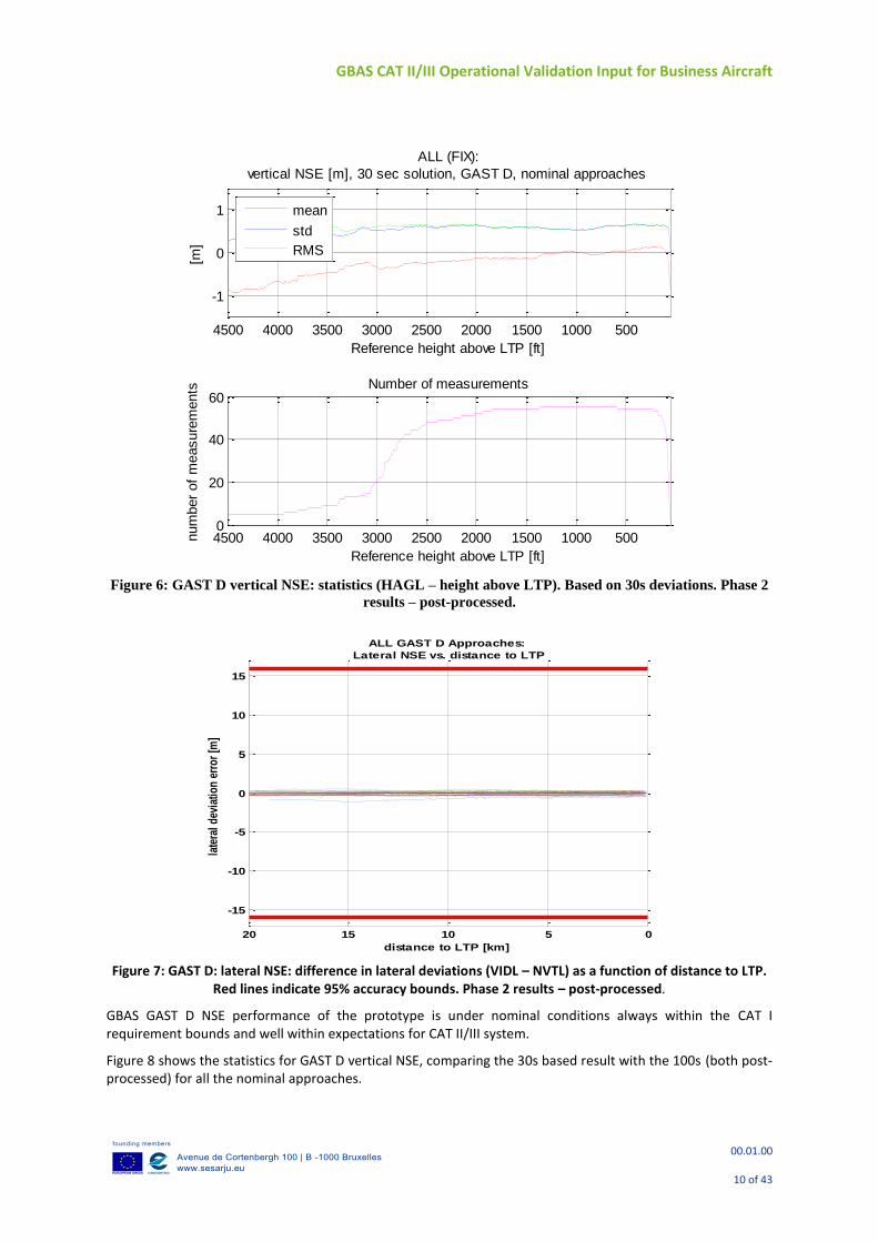
Figure 6 shows statistics for the GAST D vertical NSE for all nominal approaches as well as the number of measurement (number of approaches) included in the statistics.
Figure 7 shows lateral navigation system error of the prototype VIDL/G receiver during the GBAS GAST D nominal approaches, together with the CAT I requirement of ±16 m for 95% of time on whole approach.
Figure 5: GAST D vertical NSE: difference in vertical deviations (VIDL – NVTL) as a function of
distance to LTP. Red lines indicate 95% accuracy bounds. Phase 2 results – post-processed.
05101520-5
-4
-3
-2
-1
0
1
2
3
4
5
distance to LTP [km]
vert
ical
dev
iatio
n er
ror
[m]
ALL GAST D Approaches:
Vertical NSE vs. distance to LTP
GBAS CAT II/III Operational Validation Input for Business Aircraft
00.01.00
10 of 43
Figure 6: GAST D vertical NSE: statistics (HAGL – height above LTP). Based on 30s deviations. Phase 2
results – post-processed.
Figure 7: GAST D: lateral NSE: difference in lateral deviations (VIDL – NVTL) as a function of distance to LTP.
Red lines indicate 95% accuracy bounds. Phase 2 results – post-processed.
GBAS GAST D NSE performance of the prototype is under nominal conditions always within the CAT I requirement bounds and well within expectations for CAT II/III system.
Figure 8 shows the statistics for GAST D vertical NSE, comparing the 30s based result with the 100s (both post-processed) for all the nominal approaches.
50010001500200025003000350040004500
-1
0
1
ALL (FIX):
vertical NSE [m], 30 sec solution, GAST D, nominal approaches
Reference height above LTP [ft]
[m]
mean
std
RMS
500100015002000250030003500400045000
20
40
60Number of measurements
Reference height above LTP [ft]
num
ber
of
measure
ments
05101520
-15
-10
-5
0
5
10
15
distance to LTP [km]
late
ral
dev
iati
on
err
or
[m]
ALL GAST D Approaches:
Lateral NSE vs. distance to LTP
GBAS CAT II/III Operational Validation Input for Business Aircraft
00.01.00
11 of 43
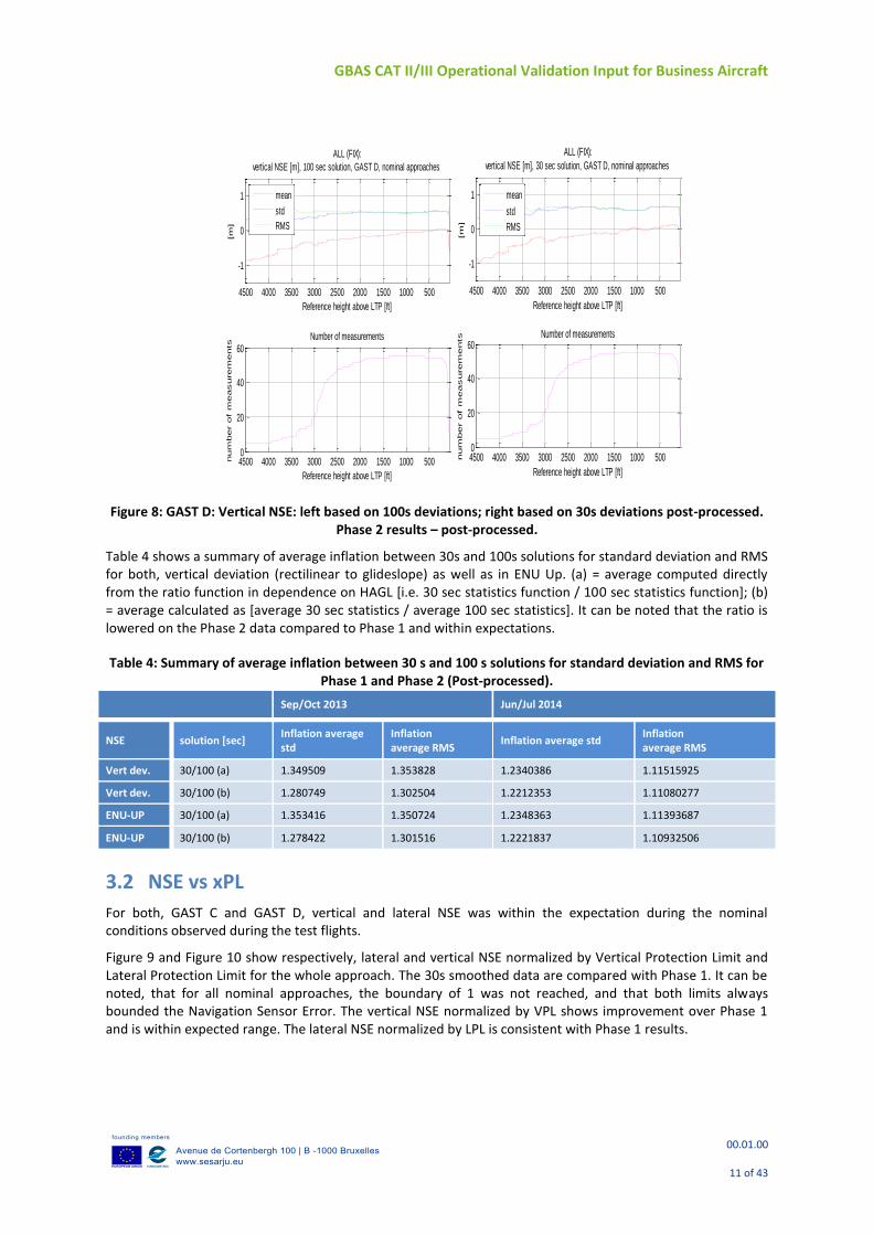
Figure 8: GAST D: Vertical NSE: left based on 100s deviations; right based on 30s deviations post-processed. Phase 2 results – post-processed.
Table 4 shows a summary of average inflation between 30s and 100s solutions for standard deviation and RMS for both, vertical deviation (rectilinear to glideslope) as well as in ENU Up. (a) = average computed directly from the ratio function in dependence on HAGL [i.e. 30 sec statistics function / 100 sec statistics function]; (b) = average calculated as [average 30 sec statistics / average 100 sec statistics]. It can be noted that the ratio is lowered on the Phase 2 data compared to Phase 1 and within expectations.
Table 4: Summary of average inflation between 30 s and 100 s solutions for standard deviation and RMS for Phase 1 and Phase 2 (Post-processed).
Sep/Oct 2013 Jun/Jul 2014
NSE solution [sec] Inflation average std
Inflation average RMS
Inflation average std Inflation average RMS
Vert dev. 30/100 (a) 1.349509 1.353828 1.2340386 1.11515925
Vert dev. 30/100 (b) 1.280749 1.302504 1.2212353 1.11080277
ENU-UP 30/100 (a) 1.353416 1.350724 1.2348363 1.11393687
ENU-UP 30/100 (b) 1.278422 1.301516 1.2221837 1.10932506
3.2 NSE vs xPL
For both, GAST C and GAST D, vertical and lateral NSE was within the expectation during the nominal conditions observed during the test flights.
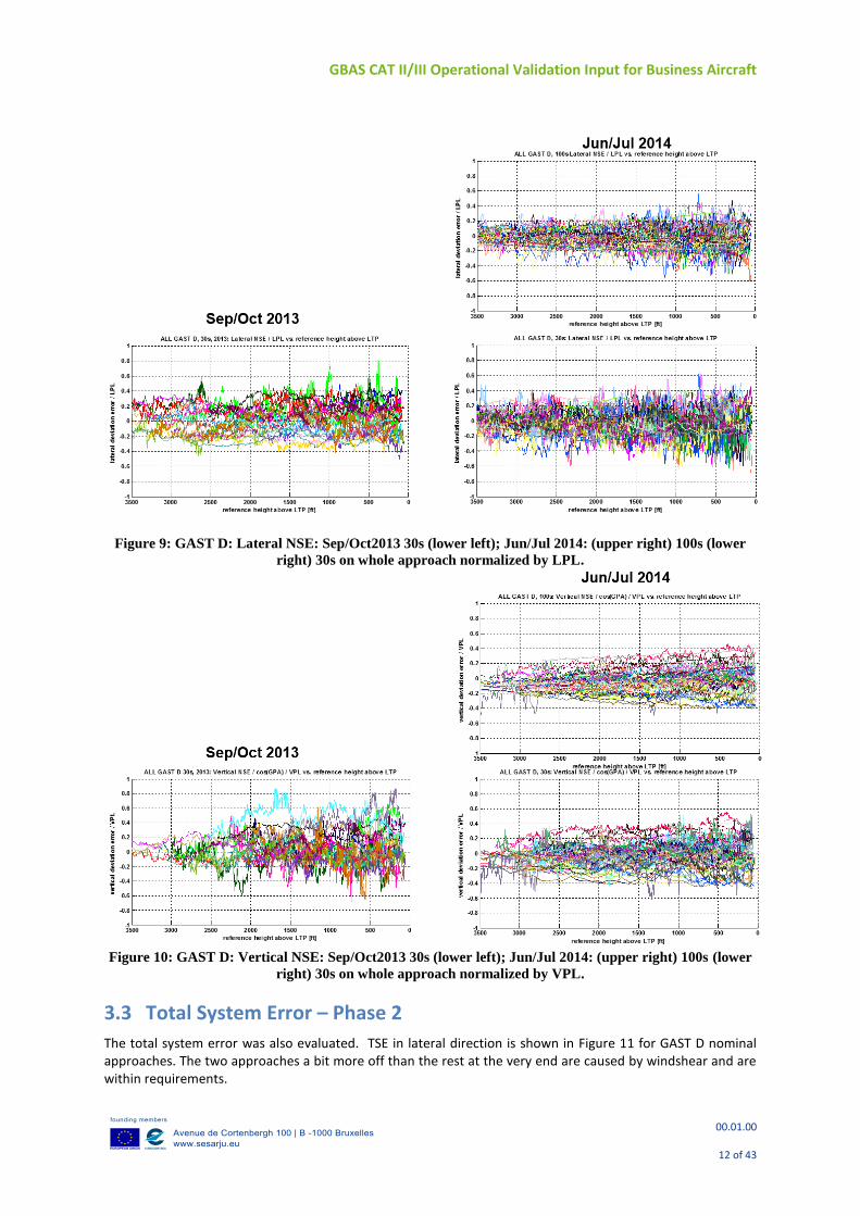
Figure 9 and Figure 10 show respectively, lateral and vertical NSE normalized by Vertical Protection Limit and Lateral Protection Limit for the whole approach. The 30s smoothed data are compared with Phase 1. It can be noted, that for all nominal approaches, the boundary of 1 was not reached, and that both limits always bounded the Navigation Sensor Error. The vertical NSE normalized by VPL shows improvement over Phase 1 and is within expected range. The lateral NSE normalized by LPL is consistent with Phase 1 results.
50010001500200025003000350040004500
-1
0
1
ALL (FIX):
vertical NSE [m], 30 sec solution, GAST D, nominal approaches
Reference height above LTP [ft]
[m
]
mean
std
RMS
500100015002000250030003500400045000
20
40
60Number of measurements
Reference height above LTP [ft]
num
ber of m
easurem
ents
50010001500200025003000350040004500
-1
0
1
ALL (FIX):
vertical NSE [m], 100 sec solution, GAST D, nominal approaches
Reference height above LTP [ft]
[m
]
mean
std
RMS
500100015002000250030003500400045000
20
40
60Number of measurements
Reference height above LTP [ft]
num
ber of m
easurem
ents
GBAS CAT II/III Operational Validation Input for Business Aircraft
00.01.00
12 of 43
Figure 9: GAST D: Lateral NSE: Sep/Oct2013 30s (lower left); Jun/Jul 2014: (upper right) 100s (lower
right) 30s on whole approach normalized by LPL.
Figure 10: GAST D: Vertical NSE: Sep/Oct2013 30s (lower left); Jun/Jul 2014: (upper right) 100s (lower
right) 30s on whole approach normalized by VPL.
3.3 Total System Error – Phase 2
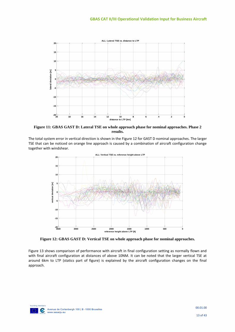
The total system error was also evaluated. TSE in lateral direction is shown in Figure 11 for GAST D nominal approaches. The two approaches a bit more off than the rest at the very end are caused by windshear and are within requirements.
GBAS CAT II/III Operational Validation Input for Business Aircraft
00.01.00
13 of 43
Figure 11: GBAS GAST D: Lateral TSE on whole approach phase for nominal approaches. Phase 2
results.
The total system error in vertical direction is shown in the Figure 12 for GAST D nominal approaches. The larger TSE that can be noticed on orange line approach is caused by a combination of aircraft configuration change together with windshear.
Figure 12: GBAS GAST D: Vertical TSE on whole approach phase for nominal approaches.
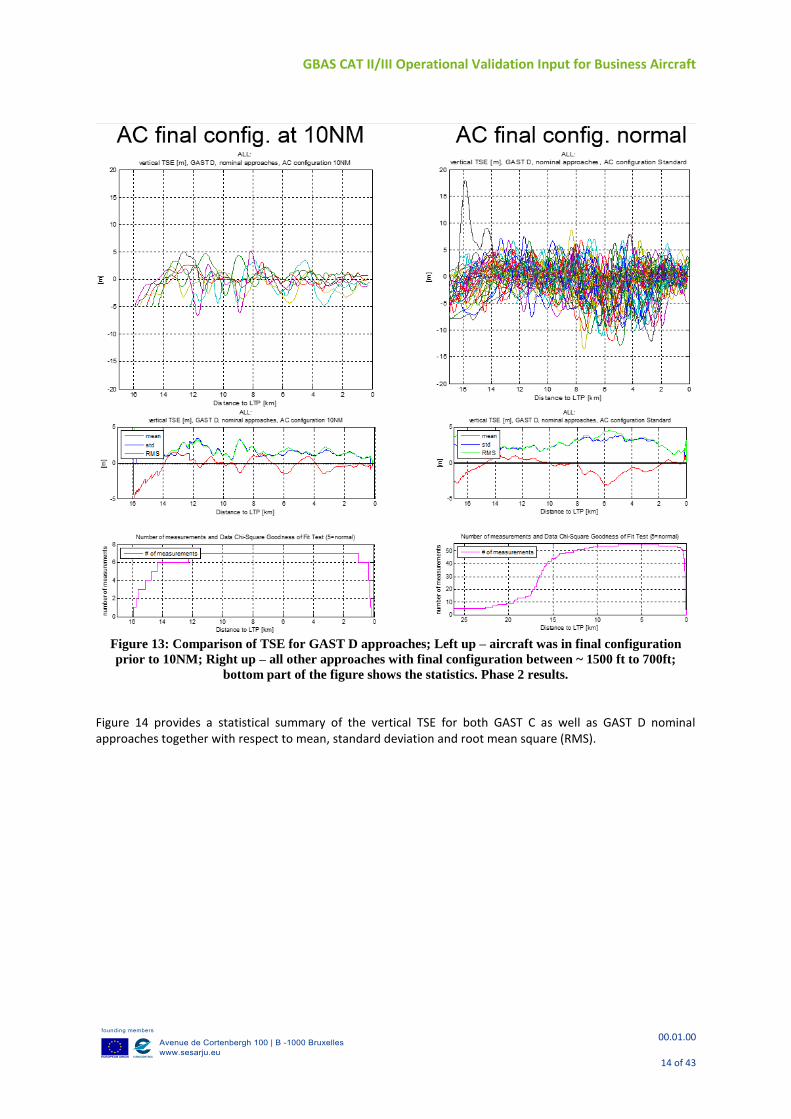
Figure 13 shows comparison of performance with aircraft in final configuration setting as normally flown and with final aircraft configuration at distances of above 10NM. It can be noted that the larger vertical TSE at around 6km to LTP (statics part of figure) is explained by the aircraft configuration changes on the final approach.
02468101214161820-20
-15
-10
-5
0
5
10
15
20
distance to LTP [km]
late
ral
devia
tio
n [
m]
ALL: Lateral TSE vs. distance to LTP
0500100015002000250030003500-20
-15
-10
-5
0
5
10
15
20
reference height above LTP [ft]
vert
ical
devia
tio
n [
m]
ALL: Vertical TSE vs. reference height above LTP
GBAS CAT II/III Operational Validation Input for Business Aircraft
00.01.00
14 of 43
Figure 13: Comparison of TSE for GAST D approaches; Left up – aircraft was in final configuration
prior to 10NM; Right up – all other approaches with final configuration between ~ 1500 ft to 700ft;
bottom part of the figure shows the statistics. Phase 2 results.
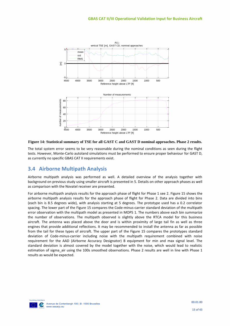
Figure 14 provides a statistical summary of the vertical TSE for both GAST C as well as GAST D nominal approaches together with respect to mean, standard deviation and root mean square (RMS).
GBAS CAT II/III Operational Validation Input for Business Aircraft
00.01.00
15 of 43
Figure 14: Statistical summary of TSE for all GAST C and GAST D nominal approaches. Phase 2 results.
The total system error seems to be very reasonable during the nominal conditions as seen during the flight tests. However, Monte-Carlo autoland simulations must be performed to ensure proper behaviour for GAST D, as currently no specific GBAS CAT II requirements exist.
3.4 Airborne Multipath Analysis
Airborne multipath analysis was performed as well. A detailed overview of the analysis together with background on previous study using smaller aircraft is presented in 5. Details on other approach phases as well as comparison with the Novatel receiver are presented.
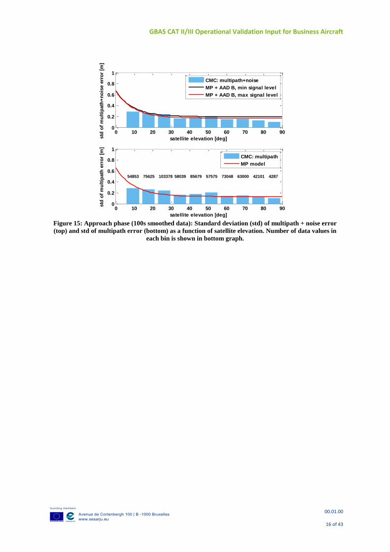
For airborne multipath analysis results for the approach phase of flight for Phase 1 see 2. Figure 15 shows the airborne multipath analysis results for the approach phase of flight for Phase 2. Data are divided into bins (each bin is 8.5 degrees wide), with analysis starting at 5 degrees. The prototype used has a 0.2 correlator spacing. The lower part of the Figure 15 compares the Code-minus-carrier standard deviation of the multipath error observation with the multipath model as presented in MOPS 1. The numbers above each bin summarize the number of observations. The multipath observed is slightly above the RTCA model for this business aircraft. The antenna was placed above the door and is within proximity of large tail fin as well as three engines that provide additional reflections. It may be recommended to install the antenna as far as possible from the tail for these types of aircraft. The upper part of the Figure 15 compares the prototypes standard deviation of Code-minus-carrier including noise with the multipath requirement combined with noise requirement for the AAD (Airborne Accuracy Designator) B equipment for min and max signal level. The standard deviation is almost covered by the model together with the noise, which would lead to realistic estimation of sigma_air using the 100s smoothed observations. Phase 2 results are well in line with Phase 1 results as would be expected.
50010001500200025003000350040004500
-5
0
5
ALL:
vertical TSE [m], GAST CD, nominal approaches
Reference height above LTP [ft]
[m]
mean
std
RMS
500100015002000250030003500400045000
20
40
60
80
Number of measurements
Reference height above LTP [ft]
num
ber
of
measure
ments
GBAS CAT II/III Operational Validation Input for Business Aircraft
00.01.00
16 of 43
Figure 15: Approach phase (100s smoothed data): Standard deviation (std) of multipath + noise error
(top) and std of multipath error (bottom) as a function of satellite elevation. Number of data values in
each bin is shown in bottom graph.
0 10 20 30 40 50 60 70 80 900
0.2
0.4
0.6
0.8
1
satellite elevation [deg]std
of
mu
ltip
ath
+n
ois
e e
rro
r [m
]
CMC: multipath+noise
MP + AAD B, min signal level
MP + AAD B, max signal level
0 10 20 30 40 50 60 70 80 900
0.2
0.4
0.6
0.8
1
satellite elevation [deg]
std
of
mu
ltip
ath
err
or
[m]
54853 75625 103378 58039 85679 57575 73048 63000 42101 4287
CMC: multipath
MP model
GBAS CAT II/III Operational Validation Input for Business Aircraft
00.01.00
17 of 43
4 FLIGHT TEST DATA ANALYSIS – PHASE 1 VS PHASE 2 PERFORMANCES
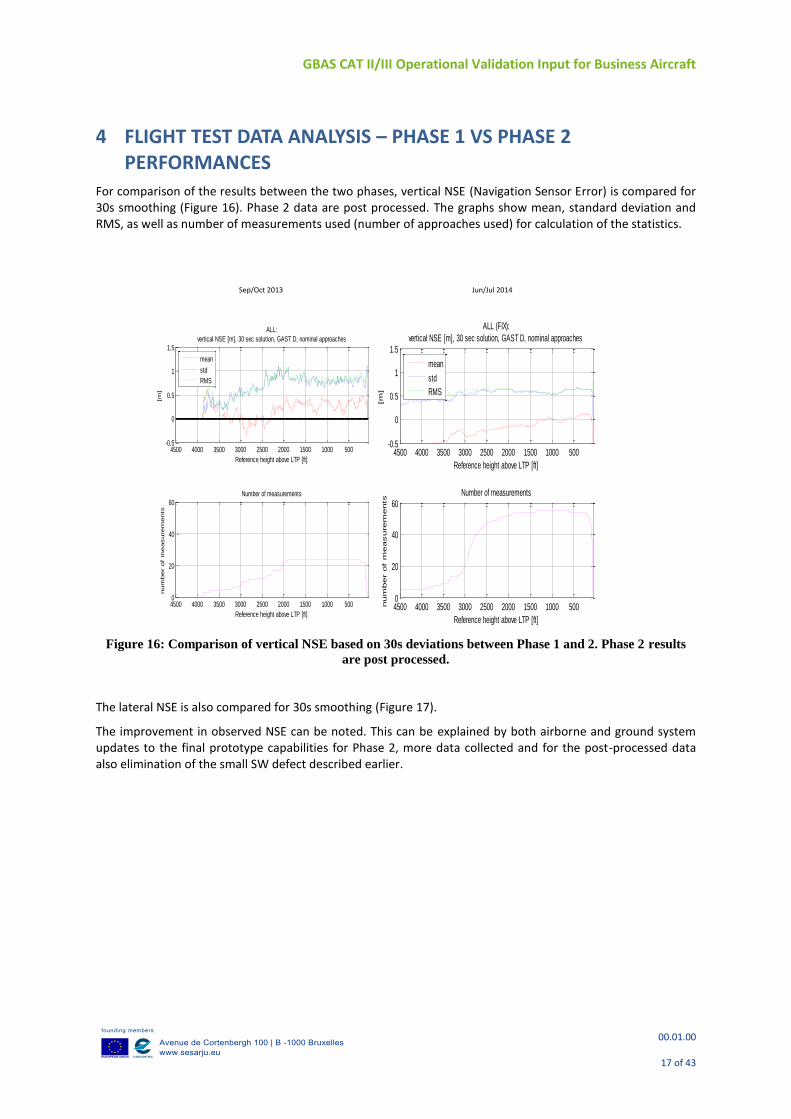
For comparison of the results between the two phases, vertical NSE (Navigation Sensor Error) is compared for 30s smoothing (Figure 16). Phase 2 data are post processed. The graphs show mean, standard deviation and RMS, as well as number of measurements used (number of approaches used) for calculation of the statistics.
Figure 16: Comparison of vertical NSE based on 30s deviations between Phase 1 and 2. Phase 2 results
are post processed.
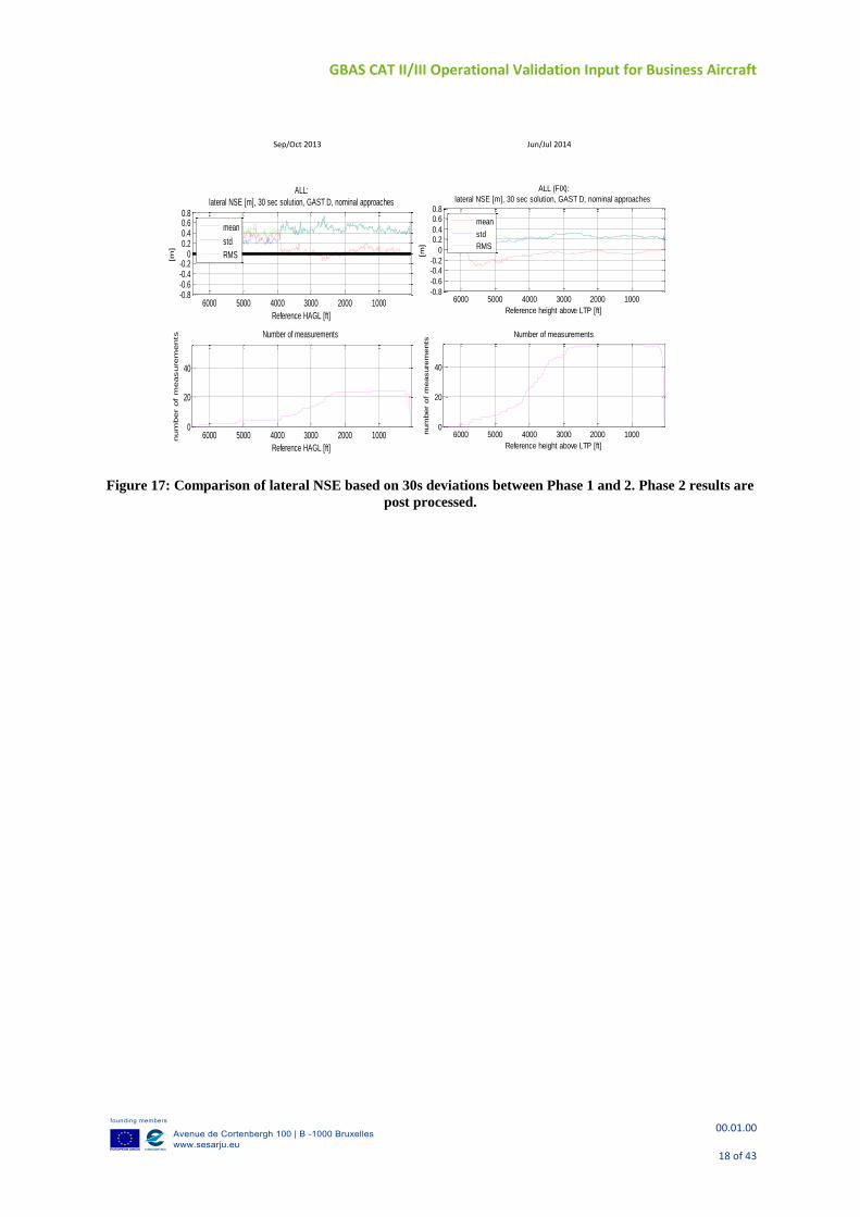
The lateral NSE is also compared for 30s smoothing (Figure 17).
The improvement in observed NSE can be noted. This can be explained by both airborne and ground system updates to the final prototype capabilities for Phase 2, more data collected and for the post-processed data also elimination of the small SW defect described earlier.
Sep/Oct 2013 Jun/Jul 2014
50010001500200025003000350040004500-0.5
0
0.5
1
1.5
ALL:
vertical NSE [m], 30 sec solution, GAST D, nominal approaches
Reference height above LTP [ft]
[m]
mean
std
RMS
500100015002000250030003500400045000
20
40
60Number of measurements
Reference height above LTP [ft]
num
ber
of
measure
ments
50010001500200025003000350040004500-0.5
0
0.5
1
1.5
ALL (FIX):
vertical NSE [m], 30 sec solution, GAST D, nominal approaches
Reference height above LTP [ft]
[m
]
mean
std
RMS
500100015002000250030003500400045000
20
40
60Number of measurements
Reference height above LTP [ft]
num
ber of m
easurem
ents
GBAS CAT II/III Operational Validation Input for Business Aircraft
00.01.00
18 of 43
Figure 17: Comparison of lateral NSE based on 30s deviations between Phase 1 and 2. Phase 2 results are
post processed.
100020003000400050006000-0.8-0.6-0.4-0.2
00.20.40.60.8
ALL:
lateral NSE [m], 30 sec solution, GAST D, nominal approaches
Reference HAGL [ft]
[m]
mean
std
RMS
1000200030004000500060000
20
40
Number of measurements
Reference HAGL [ft]
num
ber
of
measure
ments
100020003000400050006000-0.8
-0.6
-0.4-0.2
0
0.20.4
0.60.8
ALL (FIX):
lateral NSE [m], 30 sec solution, GAST D, nominal approaches
Reference height above LTP [ft]
[m]
mean
std
RMS
1000200030004000500060000
20
40
Number of measurements
Reference height above LTP [ft]
num
ber
of
measure
ments
Sep/Oct 2013 Jun/Jul 2014
GBAS CAT II/III Operational Validation Input for Business Aircraft
00.01.00
19 of 43
5 DATA ANALYSIS – MONITORS This section focuses on the specific monitors and analyses their performance mainly for the approach phase, but also provides information on the other phases for most of the cases. Monitors are divided based on the action taken, when one or more conditions specified are not fulfilled.
Monitors, which may result in Service Type Downgrade:
DSIGMA (or a subset geometry may be used),
Fault Detection (or a subset geometry may be used),
Loss of Approach Guidance,
Reference Receiver Fault Monitor (or a subset geometry may be used),
Geometry Screening (or a subset geometry may be used).
Monitors, which may result in Deviation Invalidation:
Differential Corrections Magnitude Check (invalidates/removes all deviations and differential PVT),
BAM (invalidates vertical deviations),
VDB Authentication Monitor (invalidates/removes all deviations and differential PVT).
Monitors, which may result in SV exclusion:
CCD,
(Fault Detection for SV addition).
Nominal approaches were used for the monitor analysis. The monitors’ results are here presented only for Phase 2 as the relevant updates have been performed to the receiver.
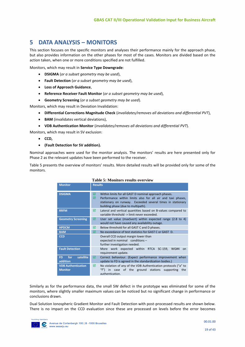
Table 5 presents the overview of monitors’ results. More detailed results will be provided only for some of the monitors.
Table 5: Monitors results overview Monitor Results
DSIGMA Within limits for all GAST D nominal approach phases. Performance within limits also for all air and taxi phases,
stationary on runway. Exceeded several times in stationary building phase (due to multipath).
RRFM Lateral and vertical quantities based on B-values compared to variable threshold -> limit never exceeded.
Geometry Screening User set value (maxSvert) within expected range (2.8 to 4) would not have caused any availability outage.
HPDCM Below threshold for all GAST C and D phases.
BAM No exceedance of test statistics for GAST C or GAST D.
CCD Overall CCD output margin lower than expected in nominal conditions – further investigation needed.
Fault Detection More work expected within RTCA SC-159, WG#4 on requirement update.
FD for satellite addition
Correct behaviour. (Expect performance improvement when update to FD is agreed in the standardization bodies.)
VDB Authentication Monitor
No violation of any of the VDB Authentication protocols (“a” to “f”) in case of the ground stations supporting the authentication.
Similarly as for the performance data, the small SW defect in the prototype was eliminated for some of the monitors, where slightly smaller maximum values can be noticed but no significant change in performance or conclusions drawn.
Dual Solution Ionospheric Gradient Monitor and Fault Detection with post-processed results are shown below. There is no impact on the CCD evaluation since these are processed on levels before the error becomes
GBAS CAT II/III Operational Validation Input for Business Aircraft
00.01.00
20 of 43
included. Slightly better performance is expected in xPL calculation, but post processed results are not included.
5.1 Dual Solution Ionospheric Gradient Monitor – Phase 2 Post Processed
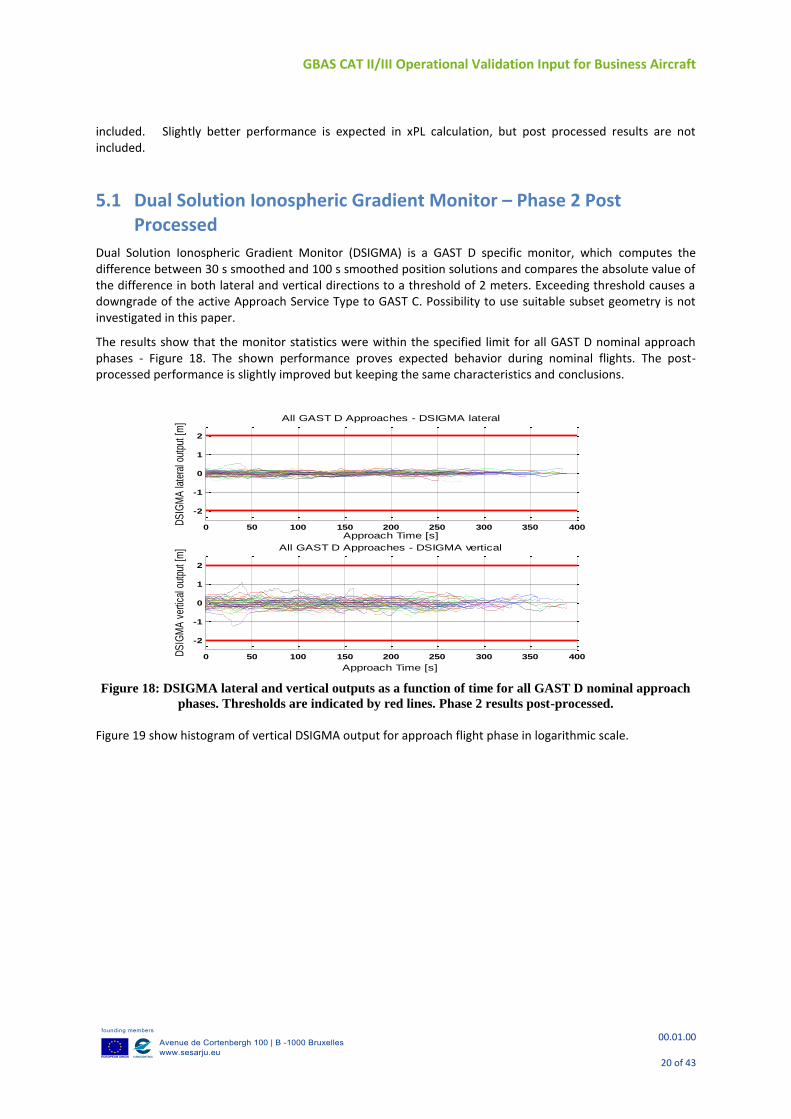
Dual Solution Ionospheric Gradient Monitor (DSIGMA) is a GAST D specific monitor, which computes the difference between 30 s smoothed and 100 s smoothed position solutions and compares the absolute value of the difference in both lateral and vertical directions to a threshold of 2 meters. Exceeding threshold causes a downgrade of the active Approach Service Type to GAST C. Possibility to use suitable subset geometry is not investigated in this paper.
The results show that the monitor statistics were within the specified limit for all GAST D nominal approach phases - Figure 18. The shown performance proves expected behavior during nominal flights. The post-processed performance is slightly improved but keeping the same characteristics and conclusions.
Figure 18: DSIGMA lateral and vertical outputs as a function of time for all GAST D nominal approach
phases. Thresholds are indicated by red lines. Phase 2 results post-processed.
Figure 19 show histogram of vertical DSIGMA output for approach flight phase in logarithmic scale.
0 50 100 150 200 250 300 350 400
-2
-1
0
1
2
Approach Time [s]
DS
IGM
A la
tera
l out
put [
m] All GAST D Approaches - DSIGMA lateral
0 50 100 150 200 250 300 350 400
-2
-1
0
1
2
Approach Time [s]
DS
IGM
A v
ertic
al o
utpu
t [m
] All GAST D Approaches - DSIGMA vertical
GBAS CAT II/III Operational Validation Input for Business Aircraft
00.01.00
21 of 43
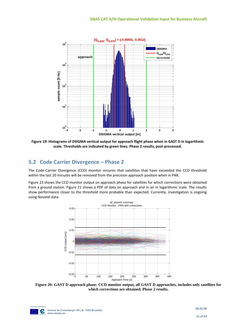
Figure 19: Histograms of DSIGMA vertical output for approach flight phase when in GAST D in logarithmic
scale. Thresholds are indicated by green lines. Phase 2 results, post-processed.
5.2 Code Carrier Divergence – Phase 2
The Code-Carrier Divergence (CCD) monitor ensures that satellites that have exceeded the CCD threshold within the last 20 minutes will be removed from the precision approach position when in PAR.
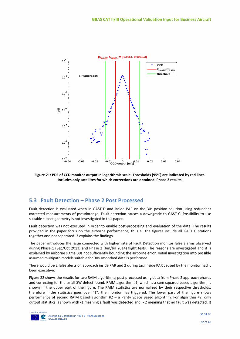
Figure 23 shows the CCD monitor output on approach phase for satellites for which corrections were obtained from a ground station. Figure 21 shows a PDF of data on approach and in air in logarithmic scale. The results show performance closer to the threshold more probable than expected. Currently, investigation is ongoing using Novatel data.
-4 -3 -2 -1 0 1 2 3 410
0
101
102
103
104
DSIGMA vertical output [m]
sam
ple
co
un
t [5
Hz]
[Q0.025
, Q0.975
] = [-0.45931, 0.3612]
approach
DSIGMA
Q0.025
/Q0.975
threshold
0 50 100 150 200 250 300 350 400-0.03
-0.02
-0.01
0
0.01
0.02
0.03
Approach Time [s]
CC
D o
utp
ut
[m/s
]
all_airports summary
CCD Monitor - PRN with corrections
Figure 20: GAST D approach phase: CCD monitor output, all GAST D approaches, includes only satellites for
which corrections are obtained. Phase 2 results.
GBAS CAT II/III Operational Validation Input for Business Aircraft
00.01.00
22 of 43
Figure 21: PDF of CCD monitor output in logarithmic scale. Thresholds (95%) are indicated by red lines.
Includes only satellites for which corrections are obtained. Phase 2 results.
5.3 Fault Detection – Phase 2 Post Processed
Fault detection is evaluated when in GAST D and inside PAR on the 30s position solution using redundant corrected measurements of pseudorange. Fault detection causes a downgrade to GAST C. Possibility to use suitable subset geometry is not investigated in this paper.
Fault detection was not executed in order to enable post-processing and evaluation of the data. The results provided in the paper focus on the airborne performance, thus all the figures include all GAST D stations together and not separated. 3 explains the findings.
The paper introduces the issue connected with higher rate of Fault Detection monitor false alarms observed during Phase 1 (Sep/Oct 2013) and Phase 2 (Jun/Jul 2014) flight tests. The reasons are investigated and it is explained by airborne sigma 30s not sufficiently bounding the airborne error. Initial investigation into possible assumed multipath models suitable for 30s smoothed data is performed.
There would be 2 false alerts on approach inside PAR and 2 during taxi inside PAR caused by the monitor had it been executive.
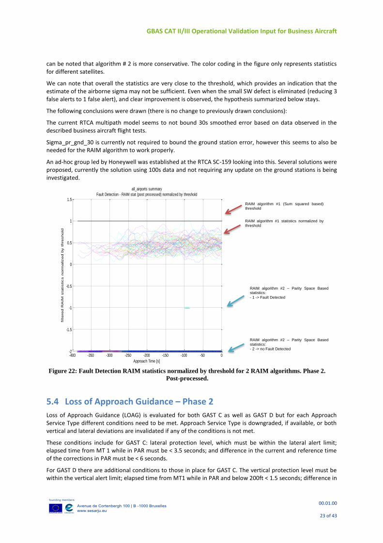
Figure 22 shows the results for two RAIM algorithms; post processed using data from Phase 2 approach phases and correcting for the small SW defect found. RAIM algorithm #1, which is a sum squared based algorithm, is shown in the upper part of the figure. The RAIM statistics are normalized by their respective thresholds, therefore if the statistics goes over “1”, the monitor has triggered. The lower part of the figure shows performance of second RAIM based algorithm #2 – a Parity Space Based algorithm. For algorithm #2, only output statistics is shown with -1 meaning a fault was detected and, - 2 meaning that no fault was detected. It
-0.04 -0.03 -0.02 -0.01 0 0.01 0.02 0.03 0.0410
-6
10-5
10-4
10-3
10-2
10-1
100
CCD output [m/s]
pd
f[Q
0.025, Q
0.975] = [-0.0051, 0.005103]
air+approach
CCD
Q0.025
/Q0.975
threshold
GBAS CAT II/III Operational Validation Input for Business Aircraft
00.01.00
23 of 43
can be noted that algorithm # 2 is more conservative. The color coding in the figure only represents statistics for different satellites.
We can note that overall the statistics are very close to the threshold, which provides an indication that the estimate of the airborne sigma may not be sufficient. Even when the small SW defect is eliminated (reducing 3 false alerts to 1 false alert), and clear improvement is observed, the hypothesis summarized below stays.
The following conclusions were drawn (there is no change to previously drawn conclusions):
The current RTCA multipath model seems to not bound 30s smoothed error based on data observed in the described business aircraft flight tests.
Sigma_pr_gnd_30 is currently not required to bound the ground station error, however this seems to also be needed for the RAIM algorithm to work properly.
An ad-hoc group led by Honeywell was established at the RTCA SC-159 looking into this. Several solutions were proposed, currently the solution using 100s data and not requiring any update on the ground stations is being investigated.
5.4 Loss of Approach Guidance – Phase 2
Loss of Approach Guidance (LOAG) is evaluated for both GAST C as well as GAST D but for each Approach Service Type different conditions need to be met. Approach Service Type is downgraded, if available, or both vertical and lateral deviations are invalidated if any of the conditions is not met.
These conditions include for GAST C: lateral protection level, which must be within the lateral alert limit; elapsed time from MT 1 while in PAR must be < 3.5 seconds; and difference in the current and reference time of the corrections in PAR must be < 6 seconds.
For GAST D there are additional conditions to those in place for GAST C. The vertical protection level must be within the vertical alert limit; elapsed time from MT1 while in PAR and below 200ft < 1.5 seconds; difference in
RAIM algorithm #1 statistics normalized by
threshold
RAIM algorithm #1 (Sum squared based) threshold
RAIM algorithm #2 – Parity Space Based statistics: - 2 -> no Fault Detected
RAIM algorithm #2 – Parity Space Based statistics:
- 1 -> Fault Detected
-400 -350 -300 -250 -200 -150 -100 -50 0-2
-1.5
-1
-0.5
0
0.5
1
1.5
Approach Time [s]
filtere
d R
AIM
sta
tistics n
orm
alized b
y t
hre
shold
all_airports summary
Fault Detection - RAIM stat (post processed) normalized by threshold
Figure 22: Fault Detection RAIM statistics normalized by threshold for 2 RAIM algorithms. Phase 2.
Post-processed.
GBAS CAT II/III Operational Validation Input for Business Aircraft
00.01.00
24 of 43
the current and reference time of the corrections in PAR and below 200ft must be < 4 seconds; elapsed time from MT11 is <3.5 seconds; and elapsed time from MT11 below 200ft must be < 1.5 seconds.
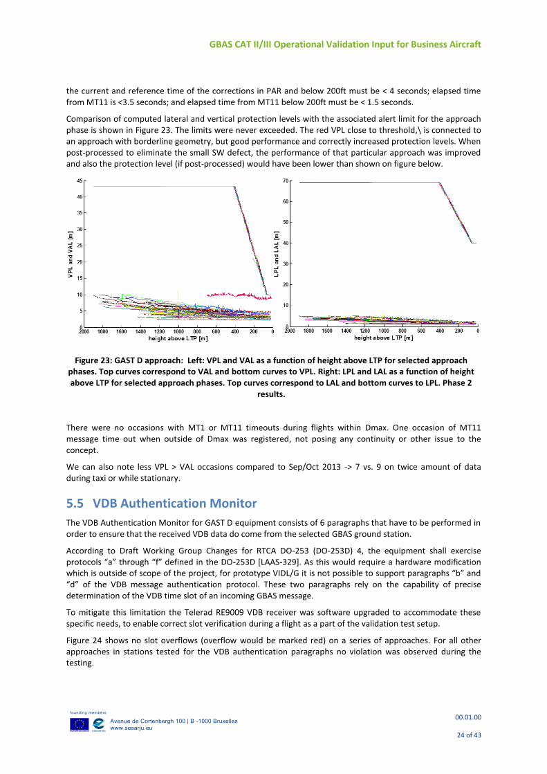
Comparison of computed lateral and vertical protection levels with the associated alert limit for the approach phase is shown in Figure 23. The limits were never exceeded. The red VPL close to threshold,\ is connected to an approach with borderline geometry, but good performance and correctly increased protection levels. When post-processed to eliminate the small SW defect, the performance of that particular approach was improved and also the protection level (if post-processed) would have been lower than shown on figure below.
There were no occasions with MT1 or MT11 timeouts during flights within Dmax. One occasion of MT11 message time out when outside of Dmax was registered, not posing any continuity or other issue to the concept.
We can also note less VPL > VAL occasions compared to Sep/Oct 2013 -> 7 vs. 9 on twice amount of data during taxi or while stationary.
5.5 VDB Authentication Monitor
The VDB Authentication Monitor for GAST D equipment consists of 6 paragraphs that have to be performed in order to ensure that the received VDB data do come from the selected GBAS ground station.
According to Draft Working Group Changes for RTCA DO-253 (DO-253D) 4, the equipment shall exercise protocols “a” through “f” defined in the DO-253D [LAAS-329]. As this would require a hardware modification which is outside of scope of the project, for prototype VIDL/G it is not possible to support paragraphs “b” and “d” of the VDB message authentication protocol. These two paragraphs rely on the capability of precise determination of the VDB time slot of an incoming GBAS message.
To mitigate this limitation the Telerad RE9009 VDB receiver was software upgraded to accommodate these specific needs, to enable correct slot verification during a flight as a part of the validation test setup.
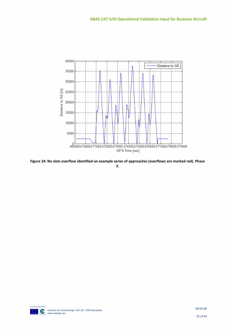
Figure 24 shows no slot overflows (overflow would be marked red) on a series of approaches. For all other approaches in stations tested for the VDB authentication paragraphs no violation was observed during the testing.
Figure 23: GAST D approach: Left: VPL and VAL as a function of height above LTP for selected approach phases. Top curves correspond to VAL and bottom curves to VPL. Right: LPL and LAL as a function of height above LTP for selected approach phases. Top curves correspond to LAL and bottom curves to LPL. Phase 2
results.
GBAS CAT II/III Operational Validation Input for Business Aircraft
00.01.00
25 of 43
Figure 24: No slots overflow identified on example series of approaches (overflows are marked red). Phase 2.
GBAS CAT II/III Operational Validation Input for Business Aircraft
00.01.00
26 of 43
6 PERFORMANCE SUMMARY Performance summary with respect to Approach Service Type Downgrades, Satellite Exclusions and Deviations Invalidation is provided in this section. The evaluation was and is performed from a different perspective than when each specific monitor was separately evaluated in previous section – now each log is evaluated for all of these possible outcomes and consistency with previous results is checked.
6.1 Approach Service Type Downgrade
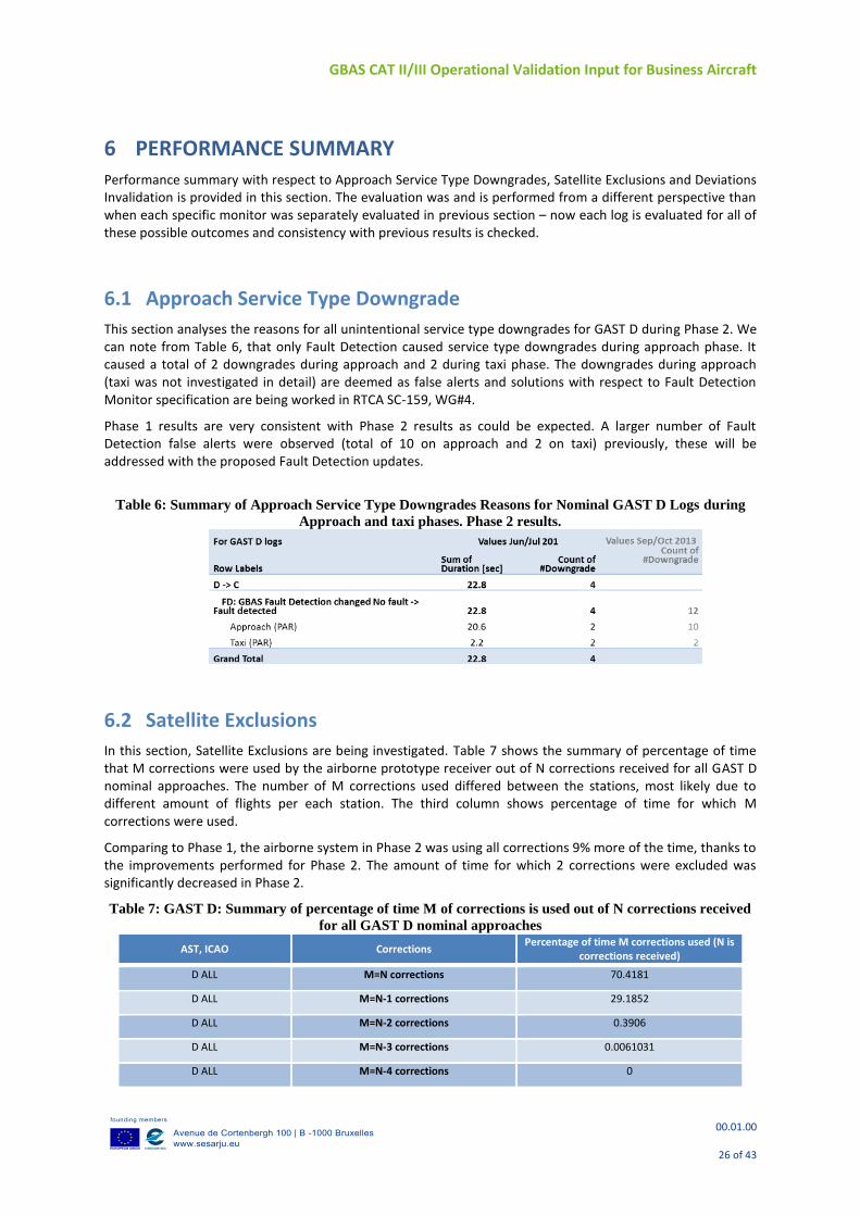
This section analyses the reasons for all unintentional service type downgrades for GAST D during Phase 2. We can note from Table 6, that only Fault Detection caused service type downgrades during approach phase. It caused a total of 2 downgrades during approach and 2 during taxi phase. The downgrades during approach (taxi was not investigated in detail) are deemed as false alerts and solutions with respect to Fault Detection Monitor specification are being worked in RTCA SC-159, WG#4.
Phase 1 results are very consistent with Phase 2 results as could be expected. A larger number of Fault Detection false alerts were observed (total of 10 on approach and 2 on taxi) previously, these will be addressed with the proposed Fault Detection updates.
Table 6: Summary of Approach Service Type Downgrades Reasons for Nominal GAST D Logs during
Approach and taxi phases. Phase 2 results.
6.2 Satellite Exclusions
In this section, Satellite Exclusions are being investigated. Table 7 shows the summary of percentage of time that M corrections were used by the airborne prototype receiver out of N corrections received for all GAST D nominal approaches. The number of M corrections used differed between the stations, most likely due to different amount of flights per each station. The third column shows percentage of time for which M corrections were used.
Comparing to Phase 1, the airborne system in Phase 2 was using all corrections 9% more of the time, thanks to the improvements performed for Phase 2. The amount of time for which 2 corrections were excluded was significantly decreased in Phase 2.
Table 7: GAST D: Summary of percentage of time M of corrections is used out of N corrections received
for all GAST D nominal approaches
AST, ICAO Corrections Percentage of time M corrections used (N is
corrections received)
D ALL M=N corrections 70.4181
D ALL M=N-1 corrections 29.1852
D ALL M=N-2 corrections 0.3906
D ALL M=N-3 corrections 0.0061031
D ALL M=N-4 corrections 0
GBAS CAT II/III Operational Validation Input for Business Aircraft
00.01.00
27 of 43
D ALL M<N-4 corrections 0
6.3 Deviations Invalidation
Deviations were not invalidated for nominal approaches during the Phase 2 flight tests.
6.4 NSE MODEL VALIDATION
Regulatory bodies require demonstrating the autoland performance of an aircraft by flight tests as well as analysis, usually based on simulations. In order to satisfy the analysis part, Monte Carlo simulations involving a generic business aircraft model and GBAS NSE model will be used. Based on EASA CS AWO and AWOHARC a performance demonstration for average risk (nominal performance), limit risk and malfunctions will be accomplished as a feasibility study only in this paper.
Honeywell GBAS simulator JLISS (Joint air-ground LAAS Integrated System Simulation), models a moving GPS constellation (Martinez or Yuma) which together with environmental models (including ionospheric and tropospheric delay, noise and multipath) is used to provide NSE in the range domain.
There are two objectives of this section. First, to describe the range domain NSE model in JLISS and then validate it by comparison to the existing position AWO HARC models (Boeing model) and by comparison with data collected during the business aircraft flight tests of Phase 2.
6.5 JLISS NSE Model Description
In the JLISS simulator, random noise components that ultimately cause nominal positional errors are generated in the pseudorange domain. In the PVT solution, they are projected into the position domain. These pseudorange errors are simulated separately for the ground and airborne parts. Random noise is usually made of thermal noise and multipath noise, each having different magnitudes and spectral properties.
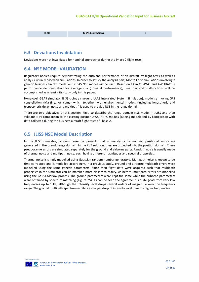
Thermal noise is simply modelled using Gaussian random number generators. Multipath noise is known to be time correlated and is modelled accordingly. In a previous study, ground and airborne multipath errors were modelled using the same generic parameters. Since then flight data were acquired such that multipath properties in the simulator can be matched more closely to reality. As before, multipath errors are modelled using the Gauss-Markov process. The ground parameters were kept the same while the airborne parameters were obtained by spectrum matching (Figure 25). As can be seen the agreement is quite good from very low frequencies up to 1 Hz, although the intensity level drops several orders of magnitude over the frequency range. The ground multipath spectrum exhibits a sharper drop of intensity level towards higher frequencies.
GBAS CAT II/III Operational Validation Input for Business Aircraft
00.01.00
28 of 43
Figure 25: Power spectra of F900 flight data and Gauss-Markov simulated data.
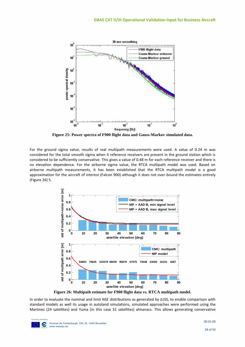
For the ground sigma value, results of real multipath measurements were used. A value of 0.24 m was considered for the total smooth sigma when 4 reference receivers are present in the ground station which is considered to be sufficiently conservative. This gives a value of 0.48 m for each reference receiver and there is no elevation dependence. For the airborne sigma value, the RTCA multipath model was used. Based on airborne multipath measurements, it has been established that the RTCA multipath model is a good approximation for the aircraft of interest (Falcon 900) although it does not over-bound the estimates entirely (Figure 26) 5.
Figure 26: Multipath estimate for F900 flight data vs. RTCA multipath model.
In order to evaluate the nominal and limit NSE distributions as generated by JLISS, to enable comparison with standard models as well its usage in autoland simulations, simulated approaches were performed using the Martinez (24 satellites) and Yuma (in this case 31 satellites) almanacs. This allows generating conservative
0 10 20 30 40 50 60 70 80 900
0.2
0.4
0.6
0.8
1
satellite elevation [deg]std
of
mu
ltip
ath
+n
ois
e e
rro
r [m
]
CMC: multipath+noise
MP + AAD B, min signal level
MP + AAD B, max signal level
0 10 20 30 40 50 60 70 80 900
0.2
0.4
0.6
0.8
1
satellite elevation [deg]
std
of
mu
ltip
ath
err
or
[m]
54853 75625 103378 58039 85679 57575 73048 63000 42101 4287
CMC: multipath
MP model
GBAS CAT II/III Operational Validation Input for Business Aircraft
00.01.00
29 of 43
results as well as more realistic results, respectively. The Yuma almanac is from July 26, 2014 which cuts through the timeframe of the Phase 2 flight campaign.
In order to do initial validation, all assumptions of the GBAS Noise model 9 as well as assumptions for the ENAC model 10 were considered and matched to those of JLISS as closely as possible. Some of the aspects are modeled differently, given the different nature of the simulations.
Simulations are run over 24 hour period at 17 airport locations similarly as in 10. Each Autoland spans approximately 4 minutes during which the first 2 minutes are spent on smoothing filter convergence and the last 2 minutes are the actual approach. Consecutive simulations are 2 minutes apart in time which results in a total of 720 simulations per day multiplied by 17 locations for a total of 12240 simulations for each set of parameters. Sigma values are computed from 8 consecutive simulations which yields 1530 standard deviations available for statistical analysis. During this accumulation interval of ~15 minutes, the satellite constellation does not change very much and it is reasonable to calculate a single standard deviation.
6.6 NSE Models Comparison
Comparison with GBAS Performance Model, which may be used for approach and landing simulations, as specified in AWOHARC material 7 is carried out.
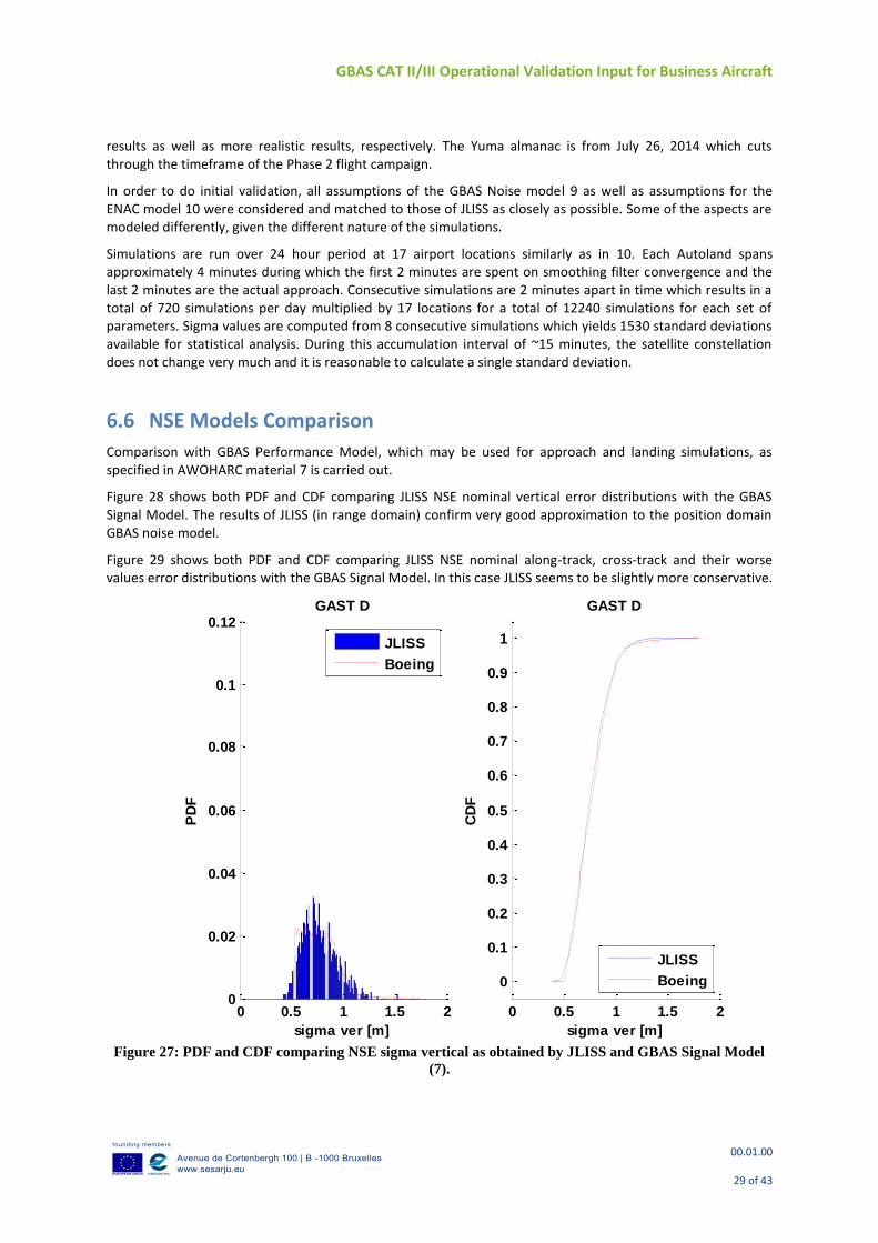
Figure 28 shows both PDF and CDF comparing JLISS NSE nominal vertical error distributions with the GBAS Signal Model. The results of JLISS (in range domain) confirm very good approximation to the position domain GBAS noise model.
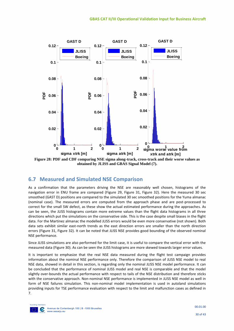
Figure 29 shows both PDF and CDF comparing JLISS NSE nominal along-track, cross-track and their worse values error distributions with the GBAS Signal Model. In this case JLISS seems to be slightly more conservative.
Figure 27: PDF and CDF comparing NSE sigma vertical as obtained by JLISS and GBAS Signal Model
(7).
0 0.5 1 1.5 20
0.02
0.04
0.06
0.08
0.1
0.12
sigma ver [m]
PD
F
GAST D
JLISS
Boeing
0 0.5 1 1.5 2
0
0.1
0.2
0.3
0.4
0.5
0.6
0.7
0.8
0.9
1
sigma ver [m]
CD
F
GAST D
JLISS
Boeing
GBAS CAT II/III Operational Validation Input for Business Aircraft
00.01.00
30 of 43
Figure 28: PDF and CDF comparing NSE sigma along-track, cross-track and their worse values as
obtained by JLISS and GBAS Signal Model (7).
6.7 Measured and Simulated NSE Comparison
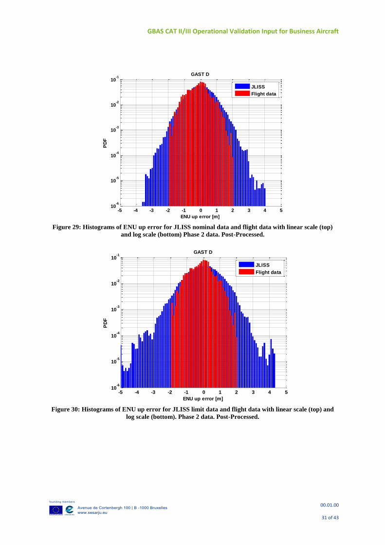
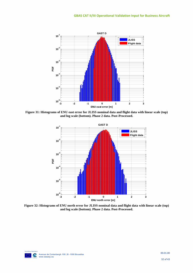
As a confirmation that the parameters driving the NSE are reasonably well chosen, histograms of the navigation error in ENU frame are compared (Figure 29, Figure 31, Figure 32). Here the measured 30 sec smoothed (GAST D) positions are compared to the simulated 30 sec smoothed positions for the Yuma almanac (nominal case). The measured errors are computed from the approach phase and are post-processed to correct for the small SW defect, as these show the actual estimated performance during the approaches. As can be seen, the JLISS histograms contain more extreme values than the flight data histograms in all three directions which put the simulations on the conservative side. This is the case despite small biases in the flight data. For the Martinez almanac the modelled JLISS errors would be even more conservative (not shown). Both data sets exhibit similar east-north trends as the east direction errors are smaller than the north direction errors (Figure 31, Figure 32). It can be noted that JLISS NSE provides good bounding of the observed nominal NSE performance.
Since JLISS simulations are also performed for the limit case, it is useful to compare the vertical error with the measured data (Figure 30). As can be seen the JLISS histograms are more skewed towards larger error values.
It is important to emphasize that the real NSE data measured during the flight test campaign provides information about the nominal NSE performance only. Therefore the comparison of JLISS NSE model to real NSE data, showed in detail in this section, is regarding only the nominal JLISS NSE model performance. It can be concluded that the performance of nominal JLISS model and real NSE is comparable and that the model slightly over-bounds the actual performance with respect to tails of the NSE distribution and therefore sticks with the conservative approach. Non-nominal NSE performance is implemented in JLISS NSE model as well in form of NSE failures simulation. This non-nominal model implementation is used in autoland simulations providing inputs for TSE performance evaluation with respect to the limit and malfunction cases as defined in 7.
0 1 20
0.02
0.04
0.06
0.08
0.1
0.12
sigma xtrk [m]
PD
FGAST D
JLISS
Boeing
0 1 20
0.02
0.04
0.06
0.08
0.1
0.12
sigma atrk [m]
PD
F
GAST D
JLISS
Boeing
0 1 20
0.02
0.04
0.06
0.08
0.1
0.12
sigma worse value from
xtrk and atrk [m]
PD
F
GAST D
JLISS
Boeing
GBAS CAT II/III Operational Validation Input for Business Aircraft
00.01.00
31 of 43
Figure 29: Histograms of ENU up error for JLISS nominal data and flight data with linear scale (top)
and log scale (bottom) Phase 2 data. Post-Processed.
Figure 30: Histograms of ENU up error for JLISS limit data and flight data with linear scale (top) and
log scale (bottom). Phase 2 data. Post-Processed.
-5 -4 -3 -2 -1 0 1 2 3 4 510
-6
10-5
10-4
10-3
10-2
10-1
ENU up error [m]
PD
F
GAST D
JLISS
Flight data
-5 -4 -3 -2 -1 0 1 2 3 4 510
-6
10-5
10-4
10-3
10-2
10-1
ENU up error [m]
PD
F
GAST D
JLISS
Flight data
GBAS CAT II/III Operational Validation Input for Business Aircraft
00.01.00
32 of 43
Figure 31: Histograms of ENU east error for JLISS nominal data and flight data with linear scale (top)
and log scale (bottom). Phase 2 data. Post-Processed.
Figure 32: Histograms of ENU north error for JLISS nominal data and flight data with linear scale (top)
and log scale (bottom). Phase 2 data. Post-Processed.
-3 -2 -1 0 1 2 310
-6
10-5
10-4
10-3
10-2
10-1
ENU east error [m]
PD
F
GAST D
JLISS
Flight data
-3 -2 -1 0 1 2 310
-6
10-5
10-4
10-3
10-2
10-1
ENU north error [m]
PD
F
GAST D
JLISS
Flight data
GBAS CAT II/III Operational Validation Input for Business Aircraft
00.01.00
33 of 43
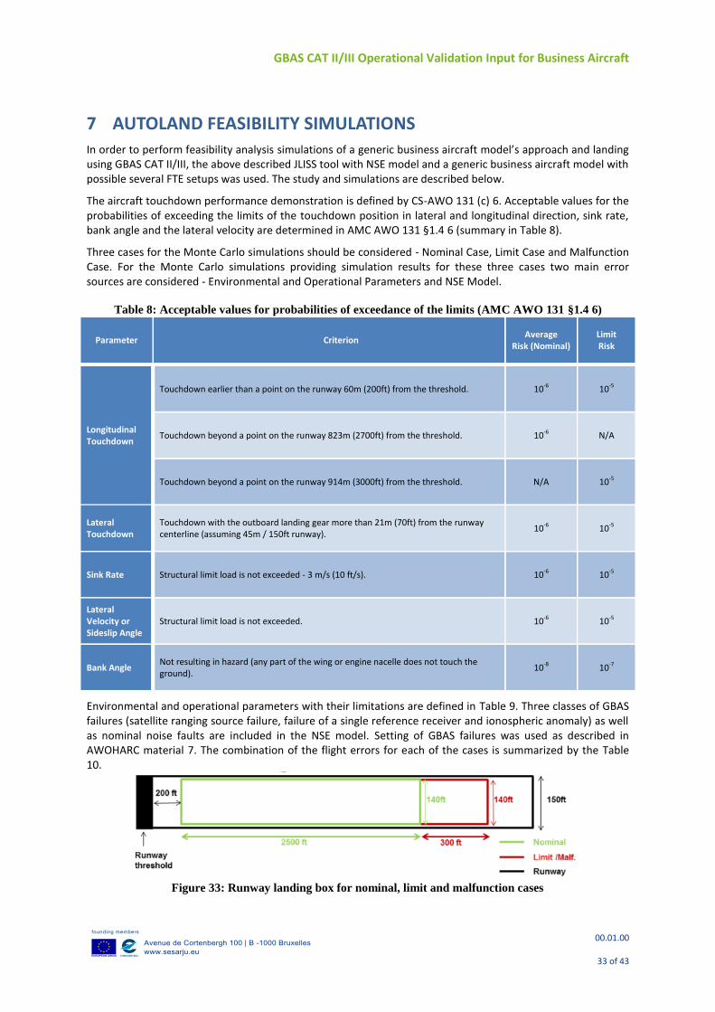
7 AUTOLAND FEASIBILITY SIMULATIONS In order to perform feasibility analysis simulations of a generic business aircraft model’s approach and landing using GBAS CAT II/III, the above described JLISS tool with NSE model and a generic business aircraft model with possible several FTE setups was used. The study and simulations are described below.
The aircraft touchdown performance demonstration is defined by CS-AWO 131 (c) 6. Acceptable values for the probabilities of exceeding the limits of the touchdown position in lateral and longitudinal direction, sink rate, bank angle and the lateral velocity are determined in AMC AWO 131 §1.4 6 (summary in Table 8).
Three cases for the Monte Carlo simulations should be considered - Nominal Case, Limit Case and Malfunction Case. For the Monte Carlo simulations providing simulation results for these three cases two main error sources are considered - Environmental and Operational Parameters and NSE Model.
Table 8: Acceptable values for probabilities of exceedance of the limits (AMC AWO 131 §1.4 6)
Parameter Criterion Average
Risk (Nominal) Limit Risk
Longitudinal Touchdown
Touchdown earlier than a point on the runway 60m (200ft) from the threshold. 10-6 10-5
Touchdown beyond a point on the runway 823m (2700ft) from the threshold. 10-6 N/A
Touchdown beyond a point on the runway 914m (3000ft) from the threshold. N/A 10-5
Lateral Touchdown
Touchdown with the outboard landing gear more than 21m (70ft) from the runway centerline (assuming 45m / 150ft runway).
10-6 10-5
Sink Rate Structural limit load is not exceeded - 3 m/s (10 ft/s). 10-6 10-5
Lateral Velocity or Sideslip Angle
Structural limit load is not exceeded. 10-6 10-5
Bank Angle Not resulting in hazard (any part of the wing or engine nacelle does not touch the ground).
10-8 10-7
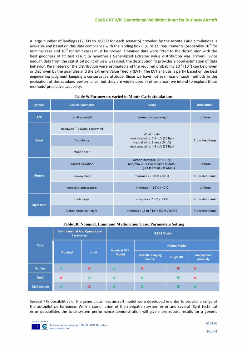
Environmental and operational parameters with their limitations are defined in Table 9. Three classes of GBAS failures (satellite ranging source failure, failure of a single reference receiver and ionospheric anomaly) as well as nominal noise faults are included in the NSE model. Setting of GBAS failures was used as described in AWOHARC material 7. The combination of the flight errors for each of the cases is summarized by the Table 10.
Figure 33: Runway landing box for nominal, limit and malfunction cases
GBAS CAT II/III Operational Validation Input for Business Aircraft
00.01.00
34 of 43
A large number of landings (12,000 to 18,000 for each scenario) provided by the Monte Carlo simulations is available and based on this data compliance with the landing box (Figure 33) requirements (probability 10
-6 for
nominal case and 10-5
for limit case) must be proven. Obtained data were fitted to the distribution with the best goodness of fit test result (a hypothesis Generalized Extreme Value distribution was proven). Since enough data from the statistical point of view was used, the distribution fit provides a good estimation of data behavior. Parameters of the distribution were estimated and the required probability 10
-6 (10
-5) can be proven
or disproven by the quantiles and the Extreme Value Theory (EVT). The EVT analysis is partly based on the best engineering judgment keeping a conservative attitude. Since we have not seen use of such methods in the evaluation of the autoland performance, but they are widely used in other areas, we intend to explore these methods’ predictive capability.
Table 9: Parameters varied in Monte Carlo simulations
Domain Varied Parameter Range Distribution
A/C Landing weight min/max landing weight Uniform
Wind
Headwind, Tailwind, Crosswind
Wind model max headwind: 7.6 m/s (25 ft/s)
max tailwind: 3 m/s (10 ft/s) max crosswind: 4.5 m/s (15 ft/s)
Truncated Gauss Turbulence
Wind shear
Airport
Airport elevation Airport database (AP SET 2):
min/max = -3.4 m /2340.3 m AMSL (-11 ft /7678.2 ft AMSL)
Uniform
Runway slope min/max = - 0.8 % / 0.8 % Truncated Gauss
Ambient temperature min/max = - 69°C / 40°C Uniform
Flight Path
Glide slope min/max = 2.85° / 3.15° Truncated Gauss
Datum Crossing Height min/max = 15 m / 18 m (50 ft / 60 ft ) Truncated Gauss
Table 10: Nominal, Limit and Malfunction Case: Parameters Setting
Case
Environmental And Operational Parameters
GBAS Model
Nominal Limit Nominal NSE
Model
Failure Model
Satellite Ranging Source
Single RR Ionospheric
Anomaly
Nominal
Limit
Malfunction
Several FTE possibilities of the generic business aircraft model were developed in order to provide a range of the autopilot performance. With a combination of the navigation system error and several flight technical error possibilities the total system performance demonstration will give more robust results for a generic
GBAS CAT II/III Operational Validation Input for Business Aircraft
00.01.00
35 of 43
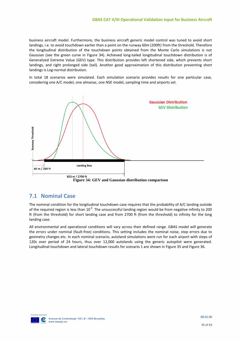
business aircraft model. Furthermore, the business aircraft generic model control was tuned to avoid short landings, i.e. to avoid touchdown earlier than a point on the runway 60m (200ft) from the threshold. Therefore the longitudinal distribution of the touchdown points obtained from the Monte Carlo simulations is not Gaussian (see the green curve in Figure 34). Achieved long-tailed longitudinal touchdown distribution is of Generalized Extreme Value (GEV) type. This distribution provides left shortened side, which prevents short landings, and right prolonged side (tail). Another good approximation of this distribution preventing short landings is Log-normal distribution.
In total 18 scenarios were simulated. Each simulation scenario provides results for one particular case, considering one A/C model, one almanac, one NSE model, sampling time and airports set.
Figure 34: GEV and Gaussian distribution comparison
7.1 Nominal Case
The nominal condition for the longitudinal touchdown case requires that the probability of A/C landing outside of the required region is less than 10
-6. The unsuccessful landing region would be from negative infinity to 200
ft (from the threshold) for short landing case and from 2700 ft (from the threshold) to infinity for the long landing case.
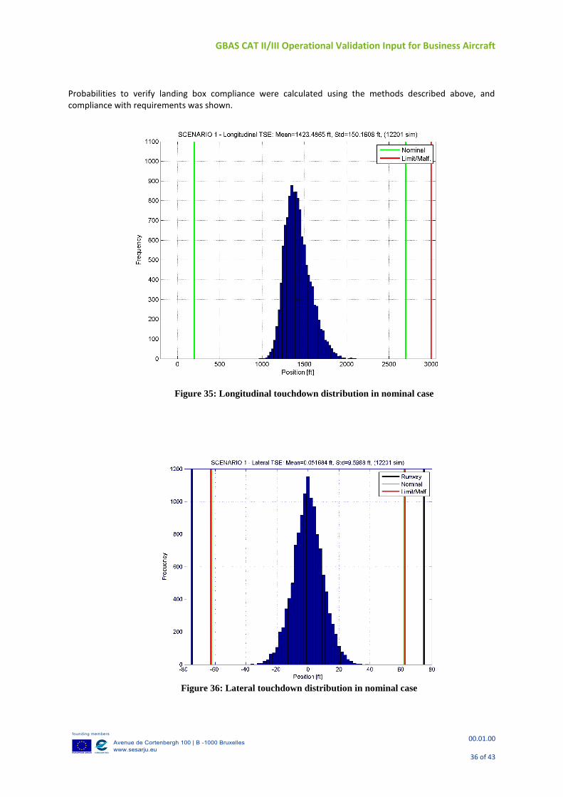
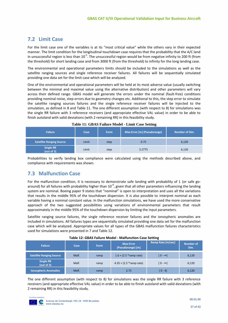
All environmental and operational conditions will vary across their defined range. GBAS model will generate the errors under nominal (fault-free) conditions. This setting includes the nominal noise, step errors due to geometry changes etc. In each nominal scenario, autoland simulations were run for each airport with steps of 120s over period of 24 hours, thus over 12,000 autolands using the generic autopilot were generated. Longitudinal touchdown and lateral touchdown results for scenario 1 are shown in Figure 35 and Figure 36.
GBAS CAT II/III Operational Validation Input for Business Aircraft
00.01.00
36 of 43
Probabilities to verify landing box compliance were calculated using the methods described above, and compliance with requirements was shown.
Figure 35: Longitudinal touchdown distribution in nominal case
Figure 36: Lateral touchdown distribution in nominal case
GBAS CAT II/III Operational Validation Input for Business Aircraft
00.01.00
37 of 43
7.2 Limit Case
For the limit case one of the variables is at its "most critical value" while the others vary in their expected manner. The limit condition for the longitudinal touchdown case requires that the probability that the A/C land in unsuccessful region is less than 10
-5. The unsuccessful region would be from negative infinity to 200 ft (from
the threshold) for short landing case and from 3000 ft (from the threshold) to infinity for the long landing case.
The environmental and operational parameters limits should be included to the simulations as well as the satellite ranging sources and single reference receiver failures. All failures will be sequentially simulated providing one data set for the limit case which will be analyzed.
One of the environmental and operational parameters will be held at its most adverse value (usually switching between the minimal and maximal value using the alternative distribution) and other parameters will vary across their defined range. GBAS model will generate the errors under the nominal (fault-free) conditions providing nominal noise, step errors due to geometry changes etc. Additional to this, the step error to simulate the satellite ranging sources failures and the single reference receiver failures will be injected to the simulation, as defined in 8 and Table 11. The one different assumption (with respect to 8) for simulations was the single RR failure with 3 reference receivers (and appropriate effective VAL value) in order to be able to finish autoland with valid deviations (with 2 remaining RR) in this feasibility study.
Table 11: GBAS Failure Model - Limit Case Setting
Failure Case Form Max Error [m] (Pseudorange) Number of Sim.
Satellite Ranging Source Limit step 0.75 6,120
Single RR (out of 3)
Limit step 3.2775 6,120
Probabilities to verify landing box compliance were calculated using the methods described above, and compliance with requirements was shown.
7.3 Malfunction Case
For the malfunction condition, it is necessary to demonstrate safe landing with probability of 1 (or safe go-around) for all failures with probability higher than 10
-9, given that all other parameters influencing the landing
system are nominal. Boeing paper 9 states that “nominal” is open to interpretation and uses all the variations that results in the middle 95% of the touchdown dispersion. It is also possible to interpret nominal as each variable having a nominal constant value. In the malfunction simulations, we have used the more conservative approach of the two suggested possibilities using variations of environmental parameters that result approximately in the middle 95% of the touchdown dispersion by limiting the input parameters.
Satellite ranging source failures, the single reference receiver failures and the ionospheric anomalies are included in simulations. All failures types are sequentially simulated providing one data set for the malfunction case which will be analyzed. Appropriate values for all types of the GBAS malfunction failures characteristics used for simulations were presented in 7 and Table 12.
Table 12: GBAS Failure Model - Malfunction Case Setting
Failure Case Form Max Error
(Pseudorange) [m]
Ramp Rate [m/sec] Number of Sim.
Satellite Ranging Source Malf. ramp 1.6 + (2.5 *ramp rate) [ 0 - ∞] 6,120
Single RR (out of 3)
Malf. ramp 4.35 + (2.5 *ramp rate) [ 0 - ∞] 6,120
Ionospheric Anomalies Malf. ramp 2.75 [ 0 - 4] 6,120
The one different assumption (with respect to 8) for simulations was the single RR failure with 3 reference receivers (and appropriate effective VAL value) in order to be able to finish autoland with valid deviations (with 2 remaining RR) in this feasibility study.
GBAS CAT II/III Operational Validation Input for Business Aircraft
00.01.00
38 of 43
The malfunction case shows a potential threat with steep ramps and large navigation errors at ca 300 to 200ft, which only last a few seconds, but could possibly cause an issue if not filtered out properly. For simulations this led to a few landing box exceedances (within runway). Although a more robust A/C control system behavior with appropriate filtering or control system limitations, than in the presented generic model is expected, it is highly recommended that this possibility is well reviewed and confirmed that it is covered by each the A/C (autopilot) manufacturer to avoid a potential risk.
It is necessary to say that since the autoland simulations use generic autopilot assumptions, the result shows the theoretical capability of business aircraft with the presented touchdown distribution meeting the landing requirements when using GBAS GAST D, under the conditions specified in this document and taking into account the applicable requirements documents. The results for specific business aircraft may vary depending on the specific integration and actual autopilot performance, and thus similar simulations need to be performed by an aircraft manufacturer for every aircraft model for the certification purposes.
GBAS CAT II/III Operational Validation Input for Business Aircraft
00.01.00
39 of 43
8 CONCLUSIONS
This paper focuses on providing results from an extensive flight test campaign of Phase 2 carried out with Honeywell experimental aircraft F900EX equipped with a prototype GAST D avionics receiver coupled with autopilot.
A short summary of the high level objectives as well as the results with respect to them follows below as a conclusion for the paper:
Verify performance in operational environment for business aircraft and ground stations in Phase 2, with focus on navigation system error evaluation, total system error, as well as performance of the required monitors and their impact on availability of the solution.
Navigation system error (NSE) was evaluated for both GAST C (not shown in the paper) and GAST D. As only CAT I requirement exist, it was used for both service types. NSE for GAST D was noisier as expected, due to the use of less smoothed (30s) data. An example of borderline geometry was observed – the performance was good, protection levels were high as would be expected and there was no impact on availability. A small SW defect was found in the prototype code. When data were post-processed taking care of this defect, the overall performance was improved. This data is presented in sections called post-processed. However, conclusions based on the observed data stay the same as for the post-processed data.
Total system error (TSE) was analyzed for both GAST D as well as GAST C. The range is reasonable and within expectations but confirmation of its compliance with the autoland requirements can only be achieved using Monte Carlo autoland simulations.
Analysis with respect to airborne multipath was performed also for Phase 2 and results shown are confirming expectations – larger vertical peaks for stationary phase, and multipath performance on a larger business aircraft not quite conforming with the RTCA multipath model, but in line with the multipath plus noise requirements. More information on multipath evaluation can be found in 5.
Monitor performance was analyzed as well and was conforming to expectations during nominal conditions - except for Fault Detection and CCD. Downgrade to lower approach service type during the testing was caused (4 times) by Fault Detection during approach and taxi phases. Fault Detection for satellite exclusion improvements are expected as the FD performance will be improved based on the results of investigation carried in FD working paper 3. RTCA SC-159 ad-hoc group led by Honeywell is looking into this aspect. The DSIGMA monitor caused downgrades only while stationary, due to increased levels of ground multipath as well as reflections off nearby buildings which does not cause any issue to the GAST D concept. Post-processed data with respect to the minor SW defect correction are present for DSIGMA and Fault Detection. Conclusions based on the observed data stay the same for the post-processed data.
The majority of satellite exclusions were caused by the Code-Carrier Divergence monitor, which is again very much in line with expectations. The exclusion of satellites exceeding the filter threshold never caused a downgrade or loss of availability.
With respect to the VDB performance, two analyses were performed on the collected data. The first is connected with verification of reception of data within the correct slots, which is now enabled thanks to a SW upgrade of the Telerad receiver (change in propagation guard). No slot overflows were noted in PT1 and PT2.
During the flight tests, no issues were observed with respect to the reception of VDB data from the ground stations in any of the phases of flight, during taxi and while stationary. There was 1 occasion of MT11 loss outside of Dmax which caused no issue to the overall concept. An omni-directional VOR antenna, placed at ca 14ft above ground on both sides of the aircraft vertical fin, is used to receive the VDB data.
Eurocontrol, who was present at part of the flight tests with the European ground stations, did perform an independent VDB link analysis to confirm the results. This further complements the integrity of analysis provided in paper.
GBAS CAT II/III Operational Validation Input for Business Aircraft
00.01.00
40 of 43
With respect to operational aspects, the pilots’ noted the difficulty with Dmax and not being able to observe valid lateral deviations outside of this region as in Phase 1. Also, some recommendations with respect to the GBAS FAS block definition which can be optimized (e.g. with respect to course width) is discussed in this deliverable.
Compare results with Phase 1:
Corrections and finalization of both ground and airborne parts resulted in better navigation performance. The overall GBAS Navigation system performance was improved compared to Sep/Oct 2013. The improved NSE can be explained by improvements in both airborne and ground systems, as well as more data collected. Again, also post-processed data showing corrections and improved performance are included.
The NSE normalized by Protection Levels was improved for vertical and is conforming to expectations.
Flights were performed in worse weather conditions (winds).
The total system performance (TSE) is comparable to Phase 1.
Monitors – DSIGMA, RRFM, Geometry Screening, HPDCM and BAM all performed within expectations and in consistency with results of Phase 1. Although CCD monitor requires more investigation with respect to the threshold, its Phase 2 behavior demonstrated that the small defect identified during Phase 1 was corrected successfully.
The number of outstanding items was significantly reduced; Fault Detection and possibly Fault Detection for satellite addition require more work, as discussed.
Overall, the flight tests were very successful and support the concept validation.
Validate NSE model used in Autoland simulations
The Honeywell NSE range domain model used in generic business aircraft approach and landing feasibility simulations was validated with data collected during flight tests and it bounds well the observed data. It was also compared to existing AWOHARC
Perform Approach and Landing Feasibility Simulations
Since the autoland simulations use generic autopilot assumptions, the result shows the theoretical capability of business aircraft with the assumed touchdown distribution meeting the landing requirements when using GBAS GAST D, under the conditions specified in this document and taking into account the applicable requirements documents. The results for specific business aircraft may vary depending on the specific integration and actual autopilot performance, and thus similar simulations need to be performed by an aircraft manufacturer for every aircraft model for the certification purposes.
8.1 Conclusions and Recommendations Summary Overall the business aircraft flight test campaigns were very successful. During the two phases in Sep/Oct 2013 and June/July 2014, a total of 150 approaches were flown with 3 different ground station manufacturers and the FAA, over 6 airports (3 in US and 3 in Europe) and using 7 ground stations. A large amount of exercises were performed to provide input and feedback to operational validation of the GBAS GAST D Concept.
It is important to emphasise that in spite of the significant number of the flight trials in several locations, the real performance observed during the flight test campaign provides information only about the nominal case and cannot possibly cover all the possible situations. There was very limited probability for any anomaly event observation and as expected, no such event was noticed during the flight test campaign (one approach with limit satellite geometry was noticed, however with post-processing for the small SW defect, this approach is also very much within expectations).
Several items that need more work and coordination on standardization level were noted and brought forward. One is the Fault Detection performance (and Fault Detection for Satellite addition), which is being updated within RTCA SC-159 ad-hoc group led by Honeywell. Others include CCD threshold investigation, GCID

GBAS CAT II/III Operational Validation Input for Business Aircraft
00.01.00
41 of 43
change aspects (ad-hoc group led by Airbus) and FAS block design (ad-hoc group led by Eurocontrol). Conforming to previous other projects, Dmax is deemed as a topic that should be resolved and is a limitation to the current concept. Results with respect to Geometry screening and its possible impact on availability have been presented. The malfunction case for the generic aircraft is also highlighted. Although a more robust A/C control system behaviour with appropriate filtering or control system limitations, than in the presented generic model, is expected, it is highly recommended that this possible threat is well reviewed and confirmed that it is covered by each the A/C (autopilot) manufacturer to avoid a potential risk.
GBAS CAT II/III Operational Validation Input for Business Aircraft
00.01.00
42 of 43
9 Acknowledgments The authors would like to acknowledge the whole Flight Test Operation site in Phoenix that made this flight tests possible. Special thanks go to the integration team – Don Winter, John Shaw, Kevin Hanna, and others; test pilots – Jary Engels, Sandy Wyatt, Mark Giddings, Matt Jensen; mechanics during flight campaign – Kevin Hanna and John Shaw, and last but not least to our flight test engineers – Adam Gavrich, Ryan Stromstad. Thanks to John Suddreth for updating the experimental display.
Special thanks go to the staff scientists supporting the project -John Savoy, Mats Brenner and Brian Schipper.
Many thanks to the FAA for enabling the flight testing, especially to John Warburton and Shelly Beauchamp.
The authors would also like to thank all the SESAR partners in 9.12 as well as 15.3.6 projects that enabled the interoperability testing and data collections. Special thanks go to the DFS, especially Dr. Winfried Dunkel and Olaf Weber, for excellent coordination during the flight testing, as well as enabling the specific ground data collections, as well as DSNA, especially Pierre Ladoux, for support of the testing.
GBAS CAT II/III Operational Validation Input for Business Aircraft
00.01.00
43 of 43
10 REFERENCES 1. RTCA DO-253C “Minimum Operational Performance Standards for GPS Local Area Augmentation System
Airborne Equipment”, December 16, 2008 2. Dvorska, J., Podivin, L., Musil, M., Zaviralova, L., Kren, M., "GBAS CAT II/III Business Aircraft Flight Trials
and Validation – Phase 1," Proceedings of the 27th International Technical Meeting of The Satellite Division of the Institute of Navigation (ION GNSS+ 2014), Tampa, Florida, September 2014, pp. 822-834.
3. ICAO NSP: Fault Detection Performance, September/October 2014, WG1 and WG2, WP28 4. Draft Working Group Changes for RTCA DO-253C; Prepared by: SC-159 WG-4, March 2014 (referred to as
DO-253D) 5. Dvorska, J., Musil, M., Orejas, M., Kutik, O., "Business Aircraft Multipath Analysis for GBAS CAT II/III,"
Proceedings of the 2014 International Technical Meeting of The Institute of Navigation, San Diego, California, January 2014, pp. 234-245.
6. Certification Specifications for All Weather Operations, CS-AWO, Brussels, 2003 7. ICAO NSP: Airworthiness Compliance Method – Appendix B, February 2015, WP X3 8. T. Murphy, M. Harris, C. Shively, L. Azoulai, M. Brenner, “Fault Modeling for GBAS airworthiness
assessments”, Proc. of the ION GNSS conference, Portland, Oregon, 2010. 9. Boeing, D6-83447-4: Volume IV – Determining the Vertical Alert Limit Requirements for a Level of GBAS
Service that is Appropriate to Support CAT II/III Operations, October 19, 2005 10. Neri, P., Macabiau, C., Azoulai, L., Muller, J., GBAS NSE Model for CAT II/III Autoland Simulations, IEEE
2010, ISBN-978-1-4244-5037-4/10