Embed Size (px)
Citation preview
Numerical Simulations of Vortex Shedding in Hydraulic Turbines
Daniel Dorney* NASA George C. Marshall Space Flight Center
Marshall Space Flight Center, AL
Bogdan Marcut The Boeing Company
Rocketdyne Propulsion and Power Canoga Park, CA
ABSTRACT
Turbomachines for rocket propulsion applications operate with many different working fluids and flow conditions. Oxidizer boost turbines often operate in liquid oxygen, resulting in an incompressible flow field. Vortex shedding from airfoils in this flow environment can have adverse effects on both turbine performance and durability. In this study the effects of vortex shedding in a low-pressure oxidizer turbine are investigated. Benchmark results are also presented for vortex shedding behind a circular cylinder. The predicted results are compared with available experimental data.
INTRODUCTION
Modern high-work turbines can be compact, transonic, supersonic, counter rotating, and can use a dense drive gas. The vast majority of modem rocket turbine designs fall into these categories. These turbines are often characterized by large amounts of flow unsteadiness. The flow unsteadiness can have a major impact on turbine performance and durability. For example, the Space Transportation Main Engine ( STME) fuel turbine. a high-work transonic design, was found to have an unsteady interrow shock which reduced efficiency by 2 points and increased dynamic loading by 24 percent. The Revolutionary Reusable Technology Turbopump (RRTT), which uses full flow oxygen for its drive gas, was found to shed vortices with such energy as to raise serious blade durability concerns. In both cases, the sources of the problems were uncovered before turbopump testing with the application of validated unsteady computational fluid dynamics (CFD) to the designs. In the case of the RRTT and the Alternate Turbopump Development
'Aerospace Engineer, Associate Fellow, AIAA 'Aerospace Engineer, Senior Member, AIAA.
Copyright 02004 by the American Institute of Aeronautics and Astronautics, Inc. No copyright is asserted in the United States under Title 17, U.S. Code. The US. Government has a royalty-free license to exercise all rights under the copyright claimed herein for Governmental Purposes. All other rights are reserved for the cowright owner.
1
(ATD) turbines, the unsteady CFD codes were used not just to identify problems, but also to guide designs that mitigate problems due to unsteadiness. Using unsteady flow analyses as part of the design process has led to turbine designs with higher performance and fewer dynamics problems. References 1-4 are examples of the application of unsteady CFD to rocket turbine designs.
The effects of vortex shedding in a low-pressure oxidizer turbine are focus of the current study. The numerical analysis is first tested on the benchmark case of a cylinder in water, and is then applied to the turbine operating in liquid oxygen. The predicted results have been compared with the available experimental data.
NUMERICAL ANALYSIS
The governing equations in the code, called AARDVARK, are the quasi-three-dimensional, unsteady, Navier-Stokes equations. The equations have been written in the Generalized Equation Set (GES) format (a detailed description of the GES can be found in Ref. 5). A description of the AARDVARK coddalgorithm, as well as its application to several turbine and pump test cases, is presented in Refs. 6 and 7. The general code structure is based on a well- established compressible, quasi-three-dimensional, unsteady turbomachinery flow solver [8]. It employs a system of overset 0-grids and H-grids, with the values on the 0-H boundaries being updated each time step by bilinear interpolation from the adjacent grid. The Baldwin-Lomax turbulence model is used for turbulence closure [9]. The code contains two options for the fluid properties. The first option is based on the equations of state, thermodynamic departure functions and corresponding states principle constructed by Oefelein [lo]. The second option, used only for liquids, is based on splines generated from the NIST Tables [ I l l .
American Institute of Aeronautics and Astronautics
https://ntrs.nasa.gov/search.jsp?R=20040085906 2018-05-11T01:22:02+00:00Z
CYLINDER BENCHMARK SIMULATION
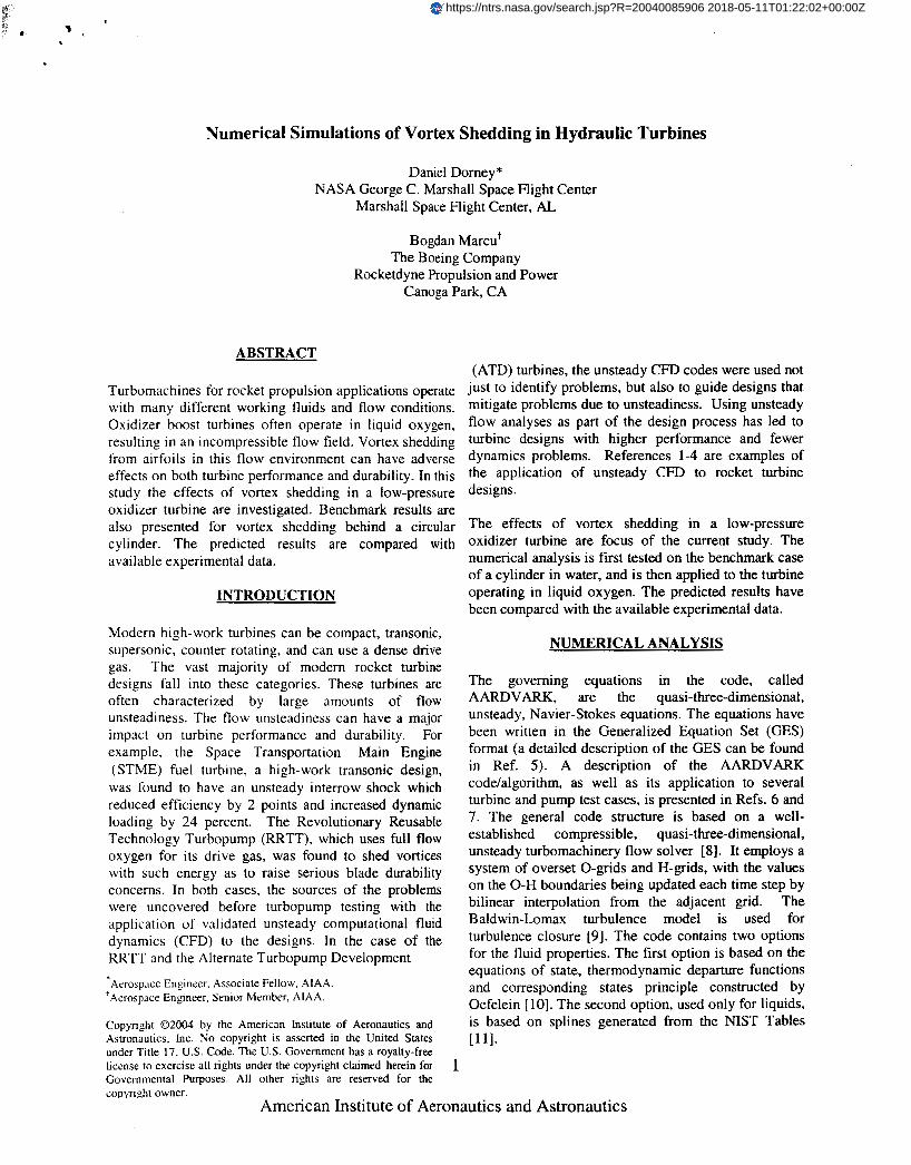
The grid topology for the cylinder contains 361x71 points in the O-grid and 142x121 points in the H-grid, for a total of 42,813 points (see Fig. 1). The average value of y+, the non-dimensional distance of the first grid point above the surface, is approximately 0.1.
The vortex shedding induces a periodic variation in the static pressure along the back half of the cylinder. Figure 3 shows the variation of the non-dimensional Static pressure as a fUnCtiOn Of time Ilea' the trailing edge stagnation Point on the cylinder.
I I I I I
Figure 1. Computational grid for the cylinder.
The Reynolds number for the benchmark simulation, Re=30,000, was chosen to approximate the Reynolds number based on the oxidizer turbine first-stage vane trailing edge diameter.
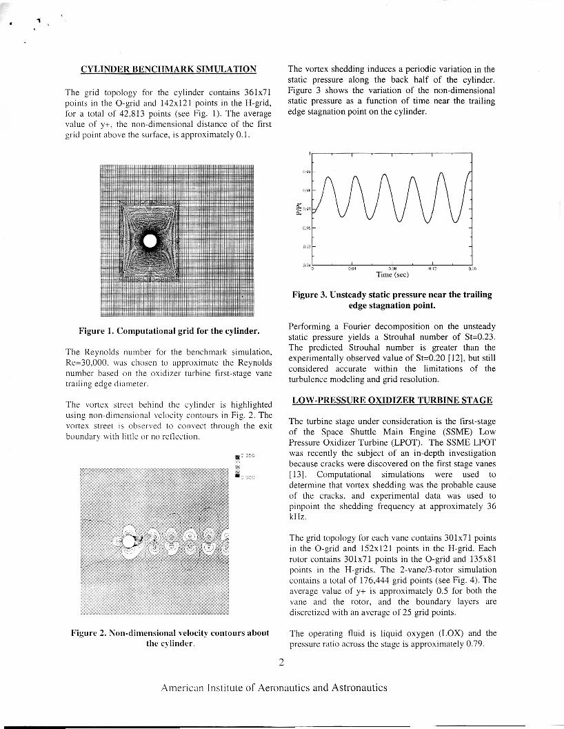
The vortex street behind the cylinder is highlighted using non-dimensional velocity contours in Fig. 2. The vortex street is observed to convect through the exit boundary with little or no reflection.
t I
OM 0.08 n 12 0.16 094
Time (sec)
Figure 3. Unsteady static pressure near the trailing edge stagnation point.
Performing a Fourier decomposition on the unsteady static pressure yields a Strouhal number of Sk0.23. The predicted Strouhal number is greater than the experimentally observed value of St=0.20 [ 121, but still considered accurate within the limitations of the turbulence modeling and grid resolution.
LOW-PRESSURE OXIDIZER TURBINE STAGE
The turbine stage under consideration is the first-stage of the Space Shuttle Main Engine (SSME) Low Pressure Oxidizer Turbine (LPOT). The SSME LPOT was recently the subject of an in-depth investigation because cracks were discovered on the first stage vanes [ 131. Computational simulations were used to determine that vortex shedding was the probable cause of the cracks, and experimental data was used to pinpoint the shedding frequency at approximately 36 kHZ .
0 250
w
I0 000
The grid topology for each vane contains 301x71 points in the 0-grid and 152x121 points in the H-grid. Each rotor contains 301x71 points in the 0-grid and 135x81 points in the H-grids. The 2-vane/3-rotor simulation contains a total of 176,444 grid points (see Fig. 4). The average value of y+ is approximately 0.5 for both the vane and the rotor, and the boundary layers are discretized with an average of 25 grid points.
The operating fluid is liquid oxygen (LOX) and the pressure ratio across the stage is approximately 0.79.
Figure 2. Non-dimensional velocity contours about the cylinder.
2
American Institute of Aeronautics and Astronautics
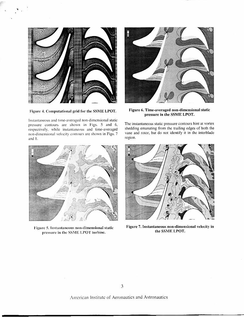
Figure 4. Computational grid for the SSME LPOT.
Instantaneous and time-averaged non-dimensional static pressure contours are shown in Figs. 5 and 6, The instantaneous static pressure contours hint at vortex respectively, while instantaneous and time-averaged shedding emanating from the trailing edges of both the non-dimensional velocity contours are shown in Figs. 7 vane and rotor, but do not identify it in the interblade and 8. region.
Figure 6. Time-averaged non-dimensional static pressure in the SSME LPOT.
Figure 5. Instantaneous non-dimensional static Iiressure in the SSME LPOT turbine.
Figure 7. Instantaneous non-dimensional velocity in the SSME LPOT.
5
American Institute of Aeronautics and Astronautics
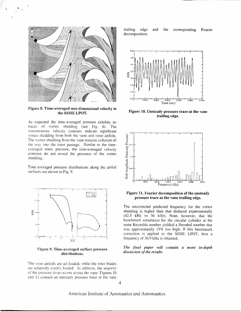
Figure 8. Time-averaged non-dimensional velocity in the SSME LPOT.
As expected the time-averaged pressure exhibits no traces of vortex shedding (see Fig. 6). The instantaneous velocity contours indicate significant vortex shedding from both the vane and rotor airfoils. The vortex shedding from the vane remains coherent all the way into the rotor passage. Similar to the time- averaged static pressure, the time-averaged velocity contours do not reveal the presence of the vortex shedding.
Time-averaged pressure distributions along the airfoil surfaces are shown in Fig. 9.
I I Y , I , , , 1 ' 1 ' 1
Figure 9. Time-averaged surface pressure distributions.
The vane airfoils are aft-loaded, while the rotor blades are relatively evenly loaded. In addition, the majority of the pressure drop occurs across the vane. Figures 10 and I 1 contain an unsteady pressure trace at the vane
trailing edge and the corresponding Fourier decomposition.
0.86 -
0 84 -
d 0.82
ii; 0.8
- -
0.78 -
0.76 -
0 7 4 G " ' 1 " ' 1 ' 1 * 0.wOI 0.W2 0.W3 O.ooo4 O.wO5 0ooo6 Time (sec)
Figure 10. Unsteady pressure trace at the vane trailing edge.
HWO IMXX) 24lxK) 32wO 4woO 4 8 0 0 Frequency (Hz)
Figure 11. Fourier decomposition of the unsteady pressure trace at the vane trailing edge.
The uncorrected predicted frequency for the vortex shedding is higher than that deduced experimentally (42.5 kHz vs 36 kHz). Note, however, that the benchmark simulation for the circular cylinder at the same Reynolds number yielded a Strouhal number that was approximately 15% too high. If this benchmark correction is applied to the SSME LPOT, then a frequency of 36.9 kHz is obtained.
The final paper will contain a more in-depth discussion of the results.
4
American Institute of Aeronautics and Astronautics
CONCLUSIONS
Unsteady numerical simulations have been performed for a circular cylinder operating in water and a low- pressure oxidizer turbine operating in liquid oxygen. The circular cylinder test case was used to validate/anchor the analysis for unsteady flows in liquids. The oxidizer turbine test case was used to study vortex shedding in a turbine that had developed cracks on the first-stage vanes. The predicted shedding frequency for the vanes, after applying a correction factor based on the cylinder simulation, is in agreement with the available experimental data
Additional conclusions will be added based on further interrogation of the results.
REFERENCES
1.
2.
3.
4.
5.
6.
7.
Griffin, L. W., and Rowey, R. J., “Analytical Investigation of the Unsteady Aerodynamic Environments in Space Shuttle Main Engine (SSME) Turbines,” ASME Paper No. 93-GT- 363, Cincinnati, OH, June, 1993. Griffin, L. W., and Huber, F. W., “Advancement of Turbine Aerodynamic Design Techniques,” ASME Paper No. 93- GT-370, Cincinnati, OH, June, 1993. Griffin, L.-W., Huber, F. W., and Sharma, 0. P., “Performance Improvement Through Indexing of Turbine Airfoils - Part 2: Numerical Simulation,” ASME Journal of Turbomachinery, Vol. 118, No. 4, 1996, pp.
Griffin, L. W. and Dorney, D. J., “Simulations of the Unsteady Flow Through the Fastrac Supersonic Turbine,” ASME Journal of Tiirbomachinery, Vol. 122, No. 2, April,
Venkateswaran, S., and Merkle, C. L., “Analysis of Preconditioning Methods for the Euler and Navier-Stokes Equations,” Von Karman Institute Lecture Series, March 8-12, 1999. Sondak, D. L. and Dorney, D. J., ”General Equation Set Solver for Compressible and Incompressible Turbomachinery Flows,” AIAA 2003-4420, 39th AIAA/ASME/SAE/ASEE Joint Propulsion Conference and Exhibit, Huntsville, AL, July
Merkle, C. L., Venkateswaran, S., Dorney, D. J., and Sondak, D. L., “A Generalized Fluid Formulation for Turbomachinery Computations,” AIAA 2003-3999, 33rd AIM
636-642.
2000, pp. 225-233.
20-23,2003.
8.
9.
10.
11. 12.
13.
Fluid Dynamics Conference and Exhibit, Orlando, FL, June 23-26,2003. Dorney, D. J., and Schwab, J. R., “Unsteady Numerical Simulations of Radial Temperature Profile Redistribution in a Single-Stage Turbine,” ASME Journal of Turbomachinery, Vol. 118, No. 4, October
Baldwin, B. S. , and Lomax, H., ‘Thin Layer Approximation and Algebraic Model for Separated Turbulent Flow,” AIAA Paper 78- 257, Huntsville, AL, January, 1978. Oefelein, J. C., Sandia Corporation, Livermore, CA, Private Communication, December, 2002. http://webbook.nist.gov/chemistry/fluid Schlichting, H., Boundary Laver Theow, Seventh Edition, McGraw-Hill Book Co., New York, 1979. Nesman, T. E., “Rocket Engine Oscillation Diagnostics,” The 2002 International Congress and Exposition on Noise Control Engineering, Paper Number N-235, Dearborn, MI, USA.
1996, pp. 783-791.
August 19-21,2002.
5
American Institute of Aeronautics and Astronautics