Embed Size (px)
Citation preview
A division of the WIKA group
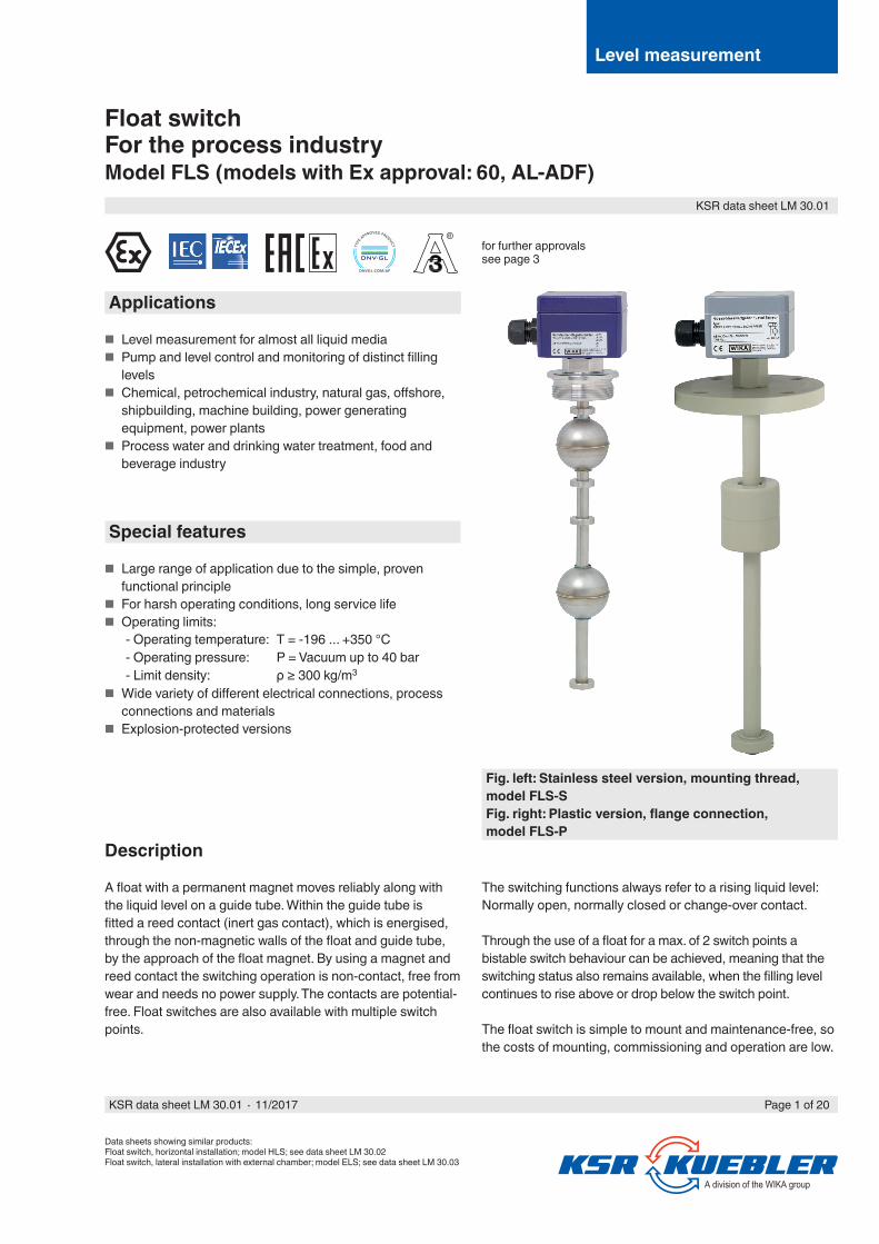
Float switchFor the process industryModel FLS (models with Ex approval: 60, AL-ADF)
Data sheets showing similar products:Float switch, horizontal installation; model HLS; see data sheet LM 30.02Float switch, lateral installation with external chamber; model ELS; see data sheet LM 30.03
Fig. left: Stainless steel version, mounting thread, model FLS-SFig. right: Plastic version, flange connection, model FLS-P
Applications
■ Level measurement for almost all liquid media ■ Pump and level control and monitoring of distinct filling
levels ■ Chemical, petrochemical industry, natural gas, offshore,
shipbuilding, machine building, power generating equipment, power plants
■ Process water and drinking water treatment, food and beverage industry
Special features
■ Large range of application due to the simple, proven functional principle
■ For harsh operating conditions, long service life ■ Operating limits:
- Operating temperature: T = -196 ... +350 °C- Operating pressure: P = Vacuum up to 40 bar- Limit density: ρ ≥ 300 kg/m3
■ Wide variety of different electrical connections, process connections and materials
■ Explosion-protected versions
Description
A float with a permanent magnet moves reliably along with the liquid level on a guide tube. Within the guide tube is fitted a reed contact (inert gas contact), which is energised, through the non-magnetic walls of the float and guide tube, by the approach of the float magnet. By using a magnet and reed contact the switching operation is non-contact, free from wear and needs no power supply. The contacts are potential-free. Float switches are also available with multiple switch points.
The switching functions always refer to a rising liquid level: Normally open, normally closed or change-over contact.
Through the use of a float for a max. of 2 switch points a bistable switch behaviour can be achieved, meaning that the switching status also remains available, when the filling level continues to rise above or drop below the switch point.
The float switch is simple to mount and maintenance-free, so the costs of mounting, commissioning and operation are low.
for further approvals see page 3
®
Level measurement
KSR data sheet LM 30.01
Page 1 of 20KSR data sheet LM 30.01 ∙ 11/2017
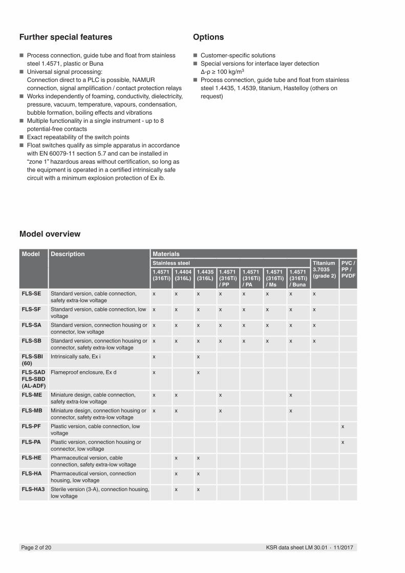
Model overview
Model Description MaterialsStainless steel Titanium
3.7035 (grade 2)
PVC / PP / PVDF
1.4571 (316Ti)
1.4404 (316L)
1.4435 (316L)
1.4571 (316Ti) / PP
1.4571 (316Ti) / PA
1.4571 (316Ti) / Ms
1.4571 (316Ti) / Buna
FLS-SE Standard version, cable connection, safety extra-low voltage
x x x x x x x x
FLS-SF Standard version, cable connection, low voltage
x x x x x x x x
FLS-SA Standard version, connection housing or connector, low voltage
x x x x x x x x
FLS-SB Standard version, connection housing or connector, safety extra-low voltage
x x x x x x x x
FLS-SBI (60)
Intrinsically safe, Ex i x x
FLS-SADFLS-SBD (AL-ADF)
Flameproof enclosure, Ex d x x
FLS-ME Miniature design, cable connection, safety extra-low voltage
x x x x
FLS-MB Miniature design, connection housing or connector, safety extra-low voltage
x x x x
FLS-PF Plastic version, cable connection, low voltage
x
FLS-PA Plastic version, connection housing or connector, low voltage
x
FLS-HE Pharmaceutical version, cable connection, safety extra-low voltage
x x
FLS-HA Pharmaceutical version, connection housing, low voltage
x x
FLS-HA3 Sterile version (3-A), connection housing, low voltage
x x
Further special features
■ Process connection, guide tube and float from stainless steel 1.4571, plastic or Buna
■ Universal signal processing:Connection direct to a PLC is possible, NAMUR connection, signal amplification / contact protection relays
■ Works independently of foaming, conductivity, dielectricity, pressure, vacuum, temperature, vapours, condensation, bubble formation, boiling effects and vibrations
■ Multiple functionality in a single instrument - up to 8 potential-free contacts
■ Exact repeatability of the switch points ■ Float switches qualify as simple apparatus in accordance
with EN 60079-11 section 5.7 and can be installed in “zone 1” hazardous areas without certification, so long as the equipment is operated in a certified intrinsically safe circuit with a minimum explosion protection of Ex ib.
Options
■ Customer-specific solutions ■ Special versions for interface layer detection
∆-ρ ≥ 100 kg/m3
■ Process connection, guide tube and float from stainless steel 1.4435, 1.4539, titanium, Hastelloy (others on request)
Page 2 of 20 KSR data sheet LM 30.01 ∙ 11/2017
Temperature range (process) ■ Models FLS-SE, FLS-SF, FLS-HE -30 ... +150 °C ■ Models FLS-SA, FLS-SB -196 ... +350 °C ■ Models FLS-SxI (60) -50 ... +180 °C ■ Models FLS-SxD (AL-ADF) -10 ... +120 °C ■ Models FLS-M -30 ... +150 °C ■ Models FLS-P -10 ... +100 °C ■ Models FLS-HA, FLS-HA3 -40 ... +200 °C
Approvals
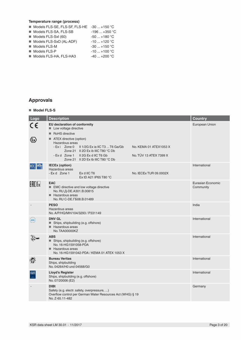
■ Model FLS-S
Logo Description CountryEU declaration of conformity
■ Low voltage directive ■ RoHS directive ■ ATEX directive (option)
Hazardous areas- Ex i Zone 0
Zone 21II 1/2G Ex ia IIC T3 ... T6 Ga/GbII 2D Ex ib IIIC T80 °C Db
No. KEMA 01 ATEX1053 X
- Ex d Zone 1Zone 21
II 2G Ex d IIC T6 GbII 2D Ex tb IIIC T80 °C Db
No. TÜV 13 ATEX 7399 X
European Union
IECEx (option)Hazardous areas- Ex d Zone 1 Ex d IIC T6
Ex tD A21 IP65 T80 °CNo. IECEx TUR 09.0002X
International
EAC ■ EMC directive and low voltage directive
No. RU Д-DE.A301.B.00815 ■ Hazardous areas
No. RU C-DE.ГБ08.B.01489
Eurasian Economic Community
- PESOHazardous areasNo. A/P/HQ/MH/104/3293 / P331149
India
DNV GL ■ Ships, shipbuilding (e.g. offshore) ■ Hazardous areas
No. TAA00000KZ
International
ABS ■ Ships, shipbuilding (e.g. offshore)
No. 16-HG1591058-PDA ■ Hazardous areas
No. 16-HG1591042-PDA / KEMA 01 ATEX 1053 X
International
Bureau VeritasShips, shipbuildingNo. 04264/H0 und 04568/G0
International
Lloyd’s RegisterShips, shipbuilding (e.g. offshore)No. 07/20006 (E2)
International
- DIBtSafety (e.g. electr. safety, overpressure, ...)Overflow control per German Water Resources Act (WHG) § 19No. Z-65.11-482
Germany
APP ROV EDTYPE
Page 3 of 20KSR data sheet LM 30.01 ∙ 11/2017
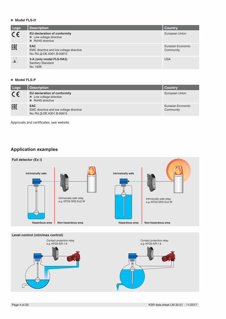
■ Model FLS-H
Logo Description CountryEU declaration of conformity
■ Low voltage directive ■ RoHS directive
European Union
EACEMC directive and low voltage directiveNo. RU Д-DE.A301.B.00815
Eurasian Economic Community
3-A (only model FLS-HA3)Sanitary StandardNo. 1698
USA
■ Model FLS-P
Logo Description CountryEU declaration of conformity
■ Low voltage directive ■ RoHS directive
European Union
EACEMC directive and low voltage directiveNo. RU Д-DE.A301.B.00815
Eurasian Economic Community
Approvals and certificates, see website
®
Application examples
Hazardous area Non-hazardous area
intrinsically safe
Intrinsically safe relaye.g. KFD2-SR2-Ex2.W
Contact protection relay e.g. KFD2-ER-1.6
Contact protection relay e.g. KFD2-ER-1.6
Full detector (Ex i)
Level control (min/max control)
Hazardous area Non-hazardous area
intrinsically safe
Intrinsically safe relaye.g. KFD2-SR2-Ex2.W
Page 4 of 20 KSR data sheet LM 30.01 ∙ 11/2017
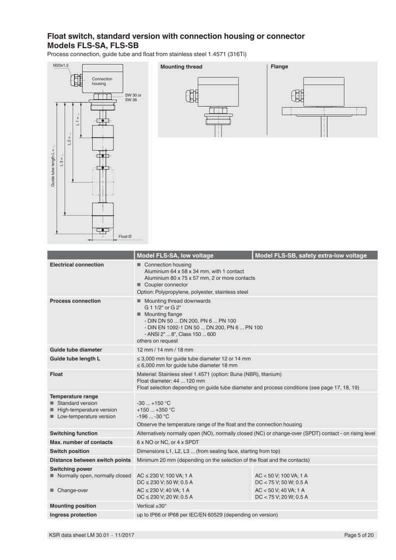
Model FLS-SA, low voltage Model FLS-SB, safety extra-low voltageElectrical connection ■ Connection housing
Aluminium 64 x 58 x 34 mm, with 1 contactAluminium 80 x 75 x 57 mm, 2 or more contacts
■ Coupler connectorOption: Polypropylene, polyester, stainless steel
Process connection ■ Mounting thread downwardsG 1 1/2" or G 2"
■ Mounting flange- DIN DN 50 ... DN 200, PN 6 ... PN 100- DIN EN 1092-1 DN 50 ... DN 200, PN 6 ... PN 100- ANSI 2" ... 8", Class 150 ... 600
others on requestGuide tube diameter 12 mm / 14 mm / 18 mmGuide tube length L ≤ 3,000 mm for guide tube diameter 12 or 14 mm
≤ 6,000 mm for guide tube diameter 18 mmFloat Material: Stainless steel 1.4571 (option: Buna (NBR), titanium)
Float diameter: 44 ... 120 mmFloat selection depending on guide tube diameter and process conditions (see page 17, 18, 19)
Temperature range ■ Standard version ■ High-temperature version ■ Low-temperature version
-30 ... +150 °C+150 ... +350 °C-196 ... -30 °CObserve the temperature range of the float and the connection housing
Switching function Alternatively normally open (NO), normally closed (NC) or change-over (SPDT) contact - on rising levelMax. number of contacts 6 x NO or NC, or 4 x SPDTSwitch position Dimensions L1, L2, L3 ... (from sealing face, starting from top)Distance between switch points Minimum 20 mm (depending on the selection of the float and the contacts)Switching power
■ Normally open, normally closed
■ Change-over
AC ≤ 230 V; 100 VA; 1 ADC ≤ 230 V; 50 W; 0.5 AAC ≤ 230 V; 40 VA; 1 ADC ≤ 230 V; 20 W; 0.5 A
AC < 50 V; 100 VA; 1 ADC < 75 V; 50 W; 0.5 AAC < 50 V; 40 VA; 1 ADC < 75 V; 20 W; 0.5 A
Mounting position Vertical ±30°Ingress protection up to IP66 or IP68 per IEC/EN 60529 (depending on version)
Float switch, standard version with connection housing or connectorModels FLS-SA, FLS-SBProcess connection, guide tube and float from stainless steel 1.4571 (316Ti)
Connection housing
Float Ø
Gui
de tu
be le
ngth
L =
...
L 1
= ...
L 2
= ...
L 3
= ...
M20x1,5
SW 30 or SW 36
Mounting thread Flange
Page 5 of 20KSR data sheet LM 30.01 ∙ 11/2017
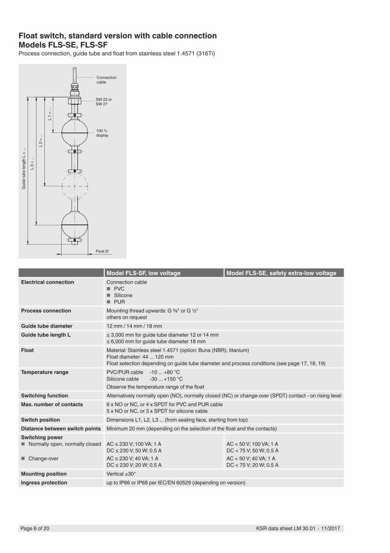
Float switch, standard version with cable connectionModels FLS-SE, FLS-SFProcess connection, guide tube and float from stainless steel 1.4571 (316Ti)
Model FLS-SF, low voltage Model FLS-SE, safety extra-low voltageElectrical connection Connection cable
■ PVC ■ Silicone ■ PUR
Process connection Mounting thread upwards: G ⅜" or G ½"others on request
Guide tube diameter 12 mm / 14 mm / 18 mmGuide tube length L ≤ 3,000 mm for guide tube diameter 12 or 14 mm
≤ 6,000 mm for guide tube diameter 18 mmFloat Material: Stainless steel 1.4571 (option: Buna (NBR), titanium)
Float diameter: 44 ... 120 mmFloat selection depending on guide tube diameter and process conditions (see page 17, 18, 19)
Temperature range PVC/PUR cable -10 ... +80 °CSilicone cable -30 ... +150 °CObserve the temperature range of the float
Switching function Alternatively normally open (NO), normally closed (NC) or change-over (SPDT) contact - on rising levelMax. number of contacts 6 x NO or NC, or 4 x SPDT for PVC and PUR cable
5 x NO or NC, or 3 x SPDT for silicone cableSwitch position Dimensions L1, L2, L3 ... (from sealing face, starting from top)Distance between switch points Minimum 20 mm (depending on the selection of the float and the contacts)Switching power
■ Normally open, normally closed
■ Change-over
AC ≤ 230 V; 100 VA; 1 ADC ≤ 230 V; 50 W; 0.5 AAC ≤ 230 V; 40 VA; 1 ADC ≤ 230 V; 20 W; 0.5 A
AC < 50 V; 100 VA; 1 ADC < 75 V; 50 W; 0.5 AAC < 50 V; 40 VA; 1 ADC < 75 V; 20 W; 0.5 A
Mounting position Vertical ±30°Ingress protection up to IP66 or IP68 per IEC/EN 60529 (depending on version)
Connection cable
Float Ø
100 % display
Gui
de tu
be le
ngth
L =
...
L 1
= ...
L 2
= ...
L 3
= ...
SW 22 or SW 27
Page 6 of 20 KSR data sheet LM 30.01 ∙ 11/2017
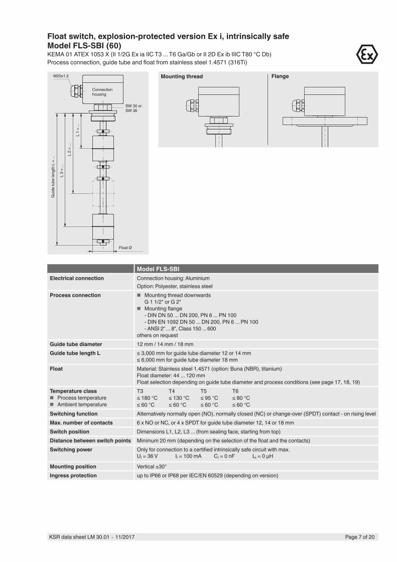
Float switch, explosion-protected version Ex i, intrinsically safeModel FLS-SBI (60)KEMA 01 ATEX 1053 X (II 1/2G Ex ia IIC T3 ... T6 Ga/Gb or II 2D Ex ib IIIC T80 °C Db)Process connection, guide tube and float from stainless steel 1.4571 (316Ti)
Model FLS-SBIElectrical connection Connection housing: Aluminium
Option: Polyester, stainless steelProcess connection ■ Mounting thread downwards
G 1 1/2" or G 2" ■ Mounting flange
- DIN DN 50 ... DN 200, PN 6 ... PN 100- DIN EN 1092 DN 50 ... DN 200, PN 6 ... PN 100- ANSI 2" ... 8", Class 150 ... 600
others on requestGuide tube diameter 12 mm / 14 mm / 18 mmGuide tube length L ≤ 3,000 mm for guide tube diameter 12 or 14 mm
≤ 6,000 mm for guide tube diameter 18 mmFloat Material: Stainless steel 1.4571 (option: Buna (NBR), titanium)
Float diameter: 44 ... 120 mmFloat selection depending on guide tube diameter and process conditions (see page 17, 18, 19)
Temperature class ■ Process temperature ■ Ambient temperature
T3 T4 T5 T6≤ 180 °C ≤ 130 °C ≤ 95 °C ≤ 80 °C≤ 60 °C ≤ 60 °C ≤ 60 °C ≤ 60 °C
Switching function Alternatively normally open (NO), normally closed (NC) or change-over (SPDT) contact - on rising levelMax. number of contacts 6 x NO or NC, or 4 x SPDT for guide tube diameter 12, 14 or 18 mmSwitch position Dimensions L1, L2, L3 ... (from sealing face, starting from top)Distance between switch points Minimum 20 mm (depending on the selection of the float and the contacts)Switching power Only for connection to a certified intrinsically safe circuit with max.
Ui = 36 V Ii = 100 mA Ci = 0 nF Li = 0 μH
Mounting position Vertical ±30°Ingress protection up to IP66 or IP68 per IEC/EN 60529 (depending on version)
Connection housing
Float Ø
Gui
de tu
be le
ngth
L =
...
L 1
= ...
L 2
= ...
L 3
= ...
M20x1,5
SW 30 or SW 36
Mounting thread Flange
Page 7 of 20KSR data sheet LM 30.01 ∙ 11/2017
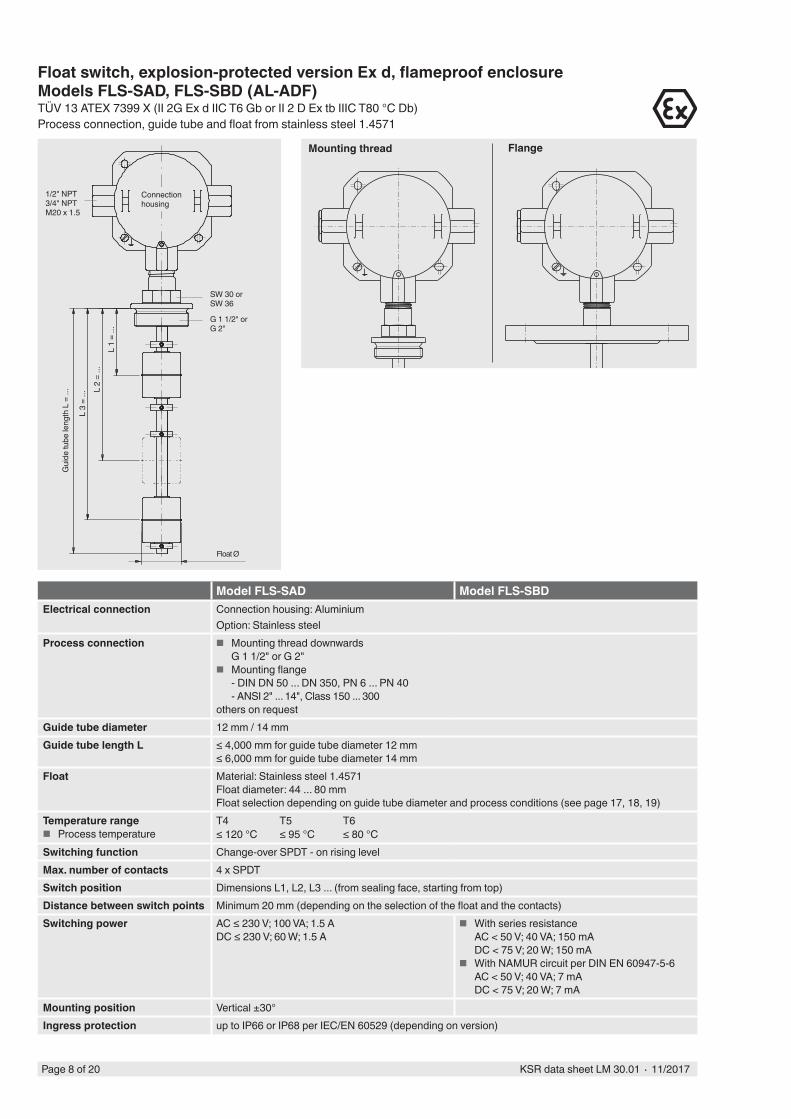
Model FLS-SAD Model FLS-SBDElectrical connection Connection housing: Aluminium
Option: Stainless steelProcess connection ■ Mounting thread downwards
G 1 1/2" or G 2" ■ Mounting flange
- DIN DN 50 ... DN 350, PN 6 ... PN 40- ANSI 2" ... 14", Class 150 ... 300
others on requestGuide tube diameter 12 mm / 14 mmGuide tube length L ≤ 4,000 mm for guide tube diameter 12 mm
≤ 6,000 mm for guide tube diameter 14 mmFloat Material: Stainless steel 1.4571
Float diameter: 44 ... 80 mmFloat selection depending on guide tube diameter and process conditions (see page 17, 18, 19)
Temperature range ■ Process temperature
T4 T5 T6≤ 120 °C ≤ 95 °C ≤ 80 °C
Switching function Change-over SPDT - on rising levelMax. number of contacts 4 x SPDTSwitch position Dimensions L1, L2, L3 ... (from sealing face, starting from top)Distance between switch points Minimum 20 mm (depending on the selection of the float and the contacts)Switching power AC ≤ 230 V; 100 VA; 1.5 A
DC ≤ 230 V; 60 W; 1.5 A ■ With series resistance
AC < 50 V; 40 VA; 150 mADC < 75 V; 20 W; 150 mA
■ With NAMUR circuit per DIN EN 60947-5-6AC < 50 V; 40 VA; 7 mADC < 75 V; 20 W; 7 mA
Mounting position Vertical ±30°Ingress protection up to IP66 or IP68 per IEC/EN 60529 (depending on version)
Page 8 of 20 KSR data sheet LM 30.01 ∙ 11/2017
Float switch, explosion-protected version Ex d, flameproof enclosureModels FLS-SAD, FLS-SBD (AL-ADF)TÜV 13 ATEX 7399 X (II 2G Ex d IIC T6 Gb or II 2 D Ex tb IIIC T80 °C Db)Process connection, guide tube and float from stainless steel 1.4571
Mounting thread Flange
Connection housing
Gui
de tu
be le
ngth
L =
...
L 3
= ...
L 1
= ...
L 2
= ...
Float Ø
1/2" NPT3/4" NPTM20 x 1.5
G 1 1/2" or G 2"
SW 30 or SW 36
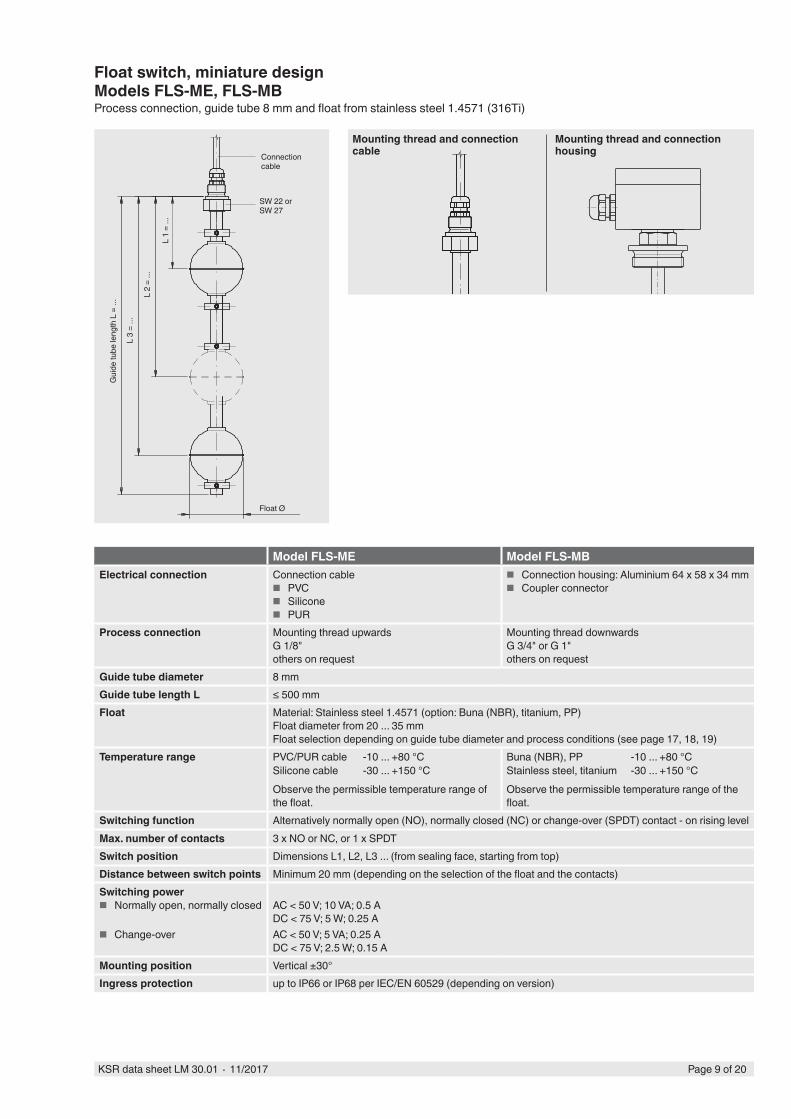
Model FLS-ME Model FLS-MBElectrical connection Connection cable
■ PVC ■ Silicone ■ PUR
■ Connection housing: Aluminium 64 x 58 x 34 mm ■ Coupler connector
Process connection Mounting thread upwardsG 1/8"others on request
Mounting thread downwardsG 3/4" or G 1"others on request
Guide tube diameter 8 mmGuide tube length L ≤ 500 mmFloat Material: Stainless steel 1.4571 (option: Buna (NBR), titanium, PP)
Float diameter from 20 ... 35 mmFloat selection depending on guide tube diameter and process conditions (see page 17, 18, 19)
Temperature range PVC/PUR cable -10 ... +80 °CSilicone cable -30 ... +150 °CObserve the permissible temperature range of the float.
Buna (NBR), PP -10 ... +80 °CStainless steel, titanium -30 ... +150 °CObserve the permissible temperature range of the float.
Switching function Alternatively normally open (NO), normally closed (NC) or change-over (SPDT) contact - on rising levelMax. number of contacts 3 x NO or NC, or 1 x SPDTSwitch position Dimensions L1, L2, L3 ... (from sealing face, starting from top)Distance between switch points Minimum 20 mm (depending on the selection of the float and the contacts)Switching power
■ Normally open, normally closed
■ Change-over
AC < 50 V; 10 VA; 0.5 ADC < 75 V; 5 W; 0.25 AAC < 50 V; 5 VA; 0.25 ADC < 75 V; 2.5 W; 0.15 A
Mounting position Vertical ±30°Ingress protection up to IP66 or IP68 per IEC/EN 60529 (depending on version)
Float switch, miniature designModels FLS-ME, FLS-MBProcess connection, guide tube 8 mm and float from stainless steel 1.4571 (316Ti)
Mounting thread and connection housing
Mounting thread and connection cableConnection
cable
Float Ø
Gui
de tu
be le
ngth
L =
...
L 1
= ...
L 2
= ...
L 3
= ...
SW 22 or SW 27
Page 9 of 20KSR data sheet LM 30.01 ∙ 11/2017
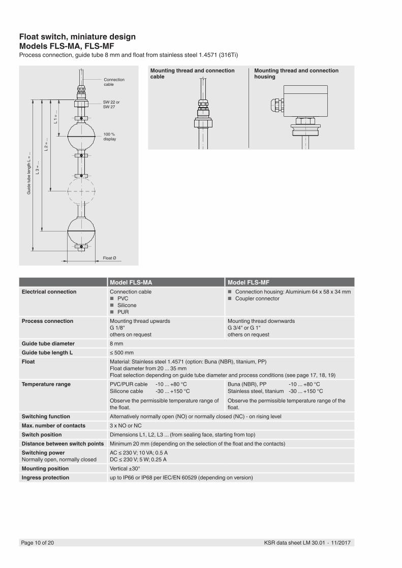
Model FLS-MA Model FLS-MFElectrical connection Connection cable
■ PVC ■ Silicone ■ PUR
■ Connection housing: Aluminium 64 x 58 x 34 mm ■ Coupler connector
Process connection Mounting thread upwardsG 1/8"others on request
Mounting thread downwardsG 3/4" or G 1"others on request
Guide tube diameter 8 mmGuide tube length L ≤ 500 mmFloat Material: Stainless steel 1.4571 (option: Buna (NBR), titanium, PP)
Float diameter from 20 ... 35 mmFloat selection depending on guide tube diameter and process conditions (see page 17, 18, 19)
Temperature range PVC/PUR cable -10 ... +80 °CSilicone cable -30 ... +150 °CObserve the permissible temperature range of the float.
Buna (NBR), PP -10 ... +80 °CStainless steel, titanium -30 ... +150 °CObserve the permissible temperature range of the float.
Switching function Alternatively normally open (NO) or normally closed (NC) - on rising levelMax. number of contacts 3 x NO or NCSwitch position Dimensions L1, L2, L3 ... (from sealing face, starting from top)Distance between switch points Minimum 20 mm (depending on the selection of the float and the contacts)Switching powerNormally open, normally closed
AC ≤ 230 V; 10 VA; 0.5 ADC ≤ 230 V; 5 W; 0.25 A
Mounting position Vertical ±30°Ingress protection up to IP66 or IP68 per IEC/EN 60529 (depending on version)
Mounting thread and connection housing
Mounting thread and connection cableConnection
cable
Float Ø
100 % display
Gui
de tu
be le
ngth
L =
...
L 1
= ...
L 2
= ...
L 3
= ...
SW 22 or SW 27
Float switch, miniature designModels FLS-MA, FLS-MFProcess connection, guide tube 8 mm and float from stainless steel 1.4571 (316Ti)
Page 10 of 20 KSR data sheet LM 30.01 ∙ 11/2017
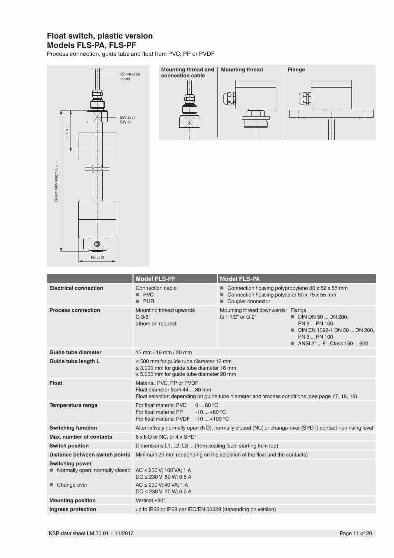
Model FLS-PF Model FLS-PAElectrical connection Connection cable
■ PVC ■ PUR
■ Connection housing polypropylene 80 x 82 x 55 mm ■ Connection housing polyester 80 x 75 x 55 mm ■ Coupler connector
Process connection Mounting thread upwardsG 3/8"others on request
Mounting thread downwardsG 1 1/2" or G 2"
Flange ■ DIN DN 50 ... DN 200,
PN 6 ... PN 100 ■ DIN EN 1092-1 DN 50 ... DN 200,
PN 6 ... PN 100 ■ ANSI 2" ... 8", Class 150 ... 600
Guide tube diameter 12 mm / 16 mm / 20 mmGuide tube length L ≤ 500 mm for guide tube diameter 12 mm
≤ 3,000 mm for guide tube diameter 16 mm≤ 5,000 mm for guide tube diameter 20 mm
Float Material: PVC, PP or PVDFFloat diameter from 44 ... 80 mmFloat selection depending on guide tube diameter and process conditions (see page 17, 18, 19)
Temperature range For float material PVC 0 ... 60 °CFor float material PP -10 ... +80 °CFor float material PVDF -10 ... +100 °C
Switching function Alternatively normally open (NO), normally closed (NC) or change-over (SPDT) contact - on rising levelMax. number of contacts 6 x NO or NC, or 4 x SPDTSwitch position Dimensions L1, L2, L3 ... (from sealing face, starting from top)Distance between switch points Minimum 20 mm (depending on the selection of the float and the contacts)Switching power
■ Normally open, normally closed
■ Change-over
AC ≤ 230 V; 100 VA; 1 ADC ≤ 230 V; 50 W; 0.5 AAC ≤ 230 V; 40 VA; 1 ADC ≤ 230 V; 20 W; 0.5 A
Mounting position Vertical ±30°Ingress protection up to IP66 or IP68 per IEC/EN 60529 (depending on version)
Float Ø
Connection cable
Gui
de tu
be le
ngth
L =
...
L 1
= ...
SW 27 or SW 32
Float switch, plastic versionModels FLS-PA, FLS-PFProcess connection, guide tube and float from PVC, PP or PVDF
Page 11 of 20KSR data sheet LM 30.01 ∙ 11/2017
Mounting thread FlangeMounting thread and connection cable
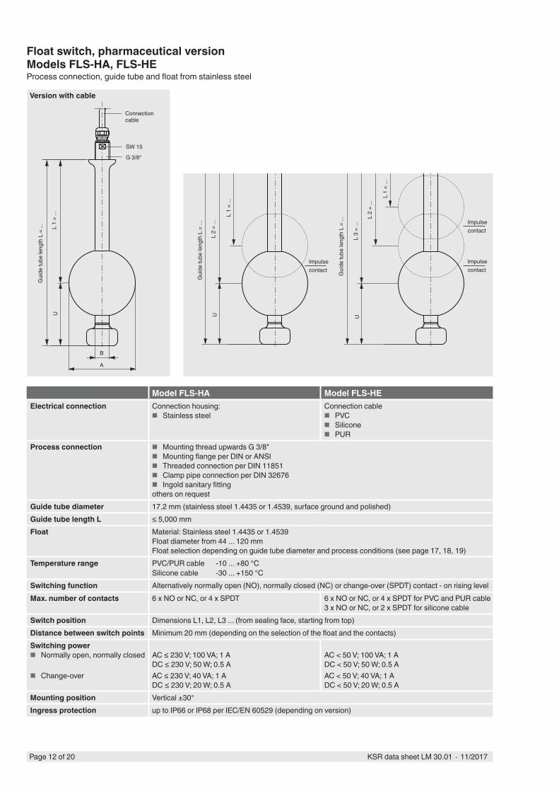
Float switch, pharmaceutical versionModels FLS-HA, FLS-HEProcess connection, guide tube and float from stainless steel
Impulse contact
Model FLS-HA Model FLS-HEElectrical connection Connection housing:
■ Stainless steelConnection cable
■ PVC ■ Silicone ■ PUR
Process connection ■ Mounting thread upwards G 3/8" ■ Mounting flange per DIN or ANSI ■ Threaded connection per DIN 11851 ■ Clamp pipe connection per DIN 32676 ■ Ingold sanitary fitting
others on requestGuide tube diameter 17.2 mm (stainless steel 1.4435 or 1.4539, surface ground and polished)Guide tube length L ≤ 5,000 mmFloat Material: Stainless steel 1.4435 or 1.4539
Float diameter from 44 ... 120 mmFloat selection depending on guide tube diameter and process conditions (see page 17, 18, 19)
Temperature range PVC/PUR cable -10 ... +80 °CSilicone cable -30 ... +150 °C
Switching function Alternatively normally open (NO), normally closed (NC) or change-over (SPDT) contact - on rising levelMax. number of contacts 6 x NO or NC, or 4 x SPDT 6 x NO or NC, or 4 x SPDT for PVC and PUR cable
3 x NO or NC, or 2 x SPDT for silicone cableSwitch position Dimensions L1, L2, L3 ... (from sealing face, starting from top)Distance between switch points Minimum 20 mm (depending on the selection of the float and the contacts)Switching power
■ Normally open, normally closed
■ Change-over
AC ≤ 230 V; 100 VA; 1 ADC ≤ 230 V; 50 W; 0.5 AAC ≤ 230 V; 40 VA; 1 ADC ≤ 230 V; 20 W; 0.5 A
AC < 50 V; 100 VA; 1 ADC < 50 V; 50 W; 0.5 AAC < 50 V; 40 VA; 1 ADC < 50 V; 20 W; 0.5 A
Mounting position Vertical ±30°Ingress protection up to IP66 or IP68 per IEC/EN 60529 (depending on version)
B
Connection cable
SW 15
Gui
de tu
be le
ngth
L =
...
L 1
= ...
Version with cable
U
A
G 3/8"
Gui
de tu
be le
ngth
L =
...
L 1
= ...
L 2
= ...
U
Gui
de tu
be le
ngth
L =
... L
2 =
...
L 3
= ...
U
L 1
= ...
Impulse contact
Impulse contact
Page 12 of 20 KSR data sheet LM 30.01 ∙ 11/2017
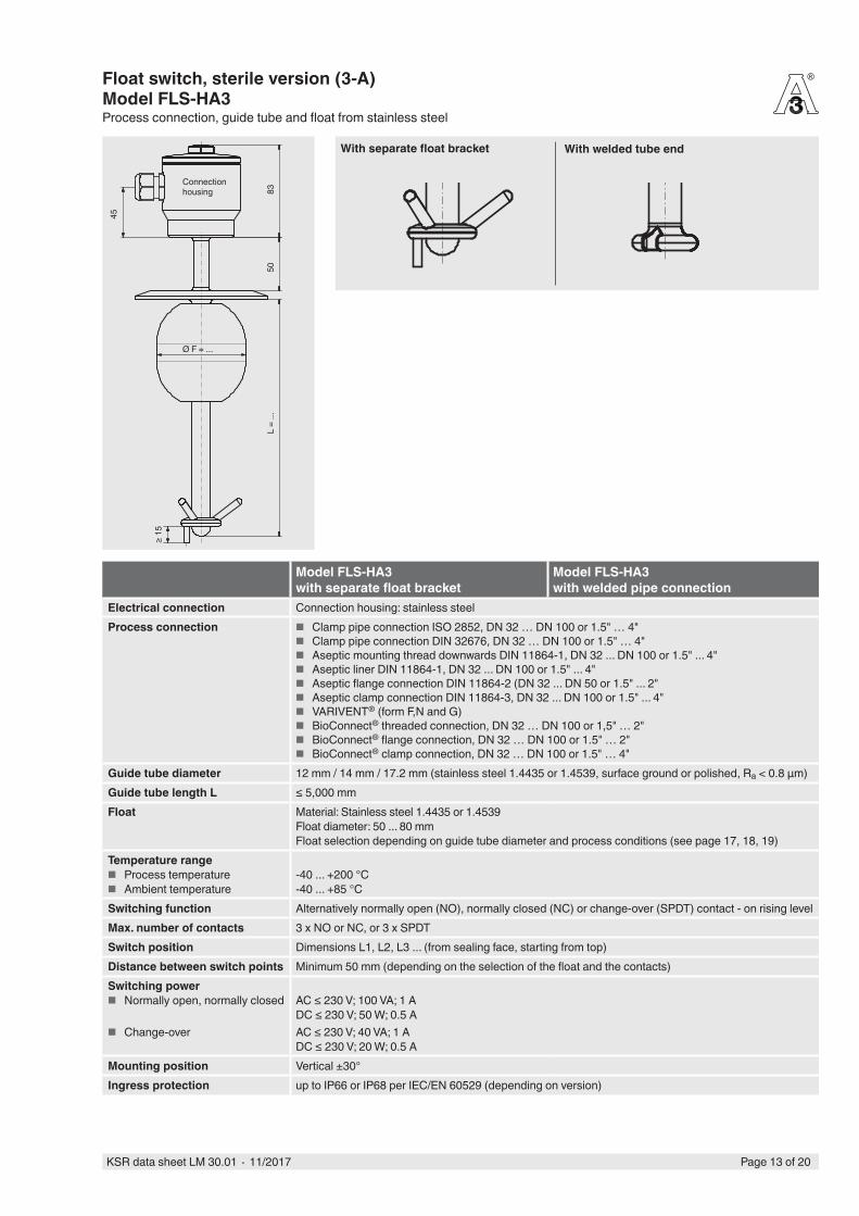
Float switch, sterile version (3-A)Model FLS-HA3Process connection, guide tube and float from stainless steel
®
Connection housing
L =
...
Ø F = ...
5083
45
≥ 15
Model FLS-HA3with separate float bracket
Model FLS-HA3with welded pipe connection
Electrical connection Connection housing: stainless steelProcess connection ■ Clamp pipe connection ISO 2852, DN 32 … DN 100 or 1.5" … 4"
■ Clamp pipe connection DIN 32676, DN 32 … DN 100 or 1.5" … 4" ■ Aseptic mounting thread downwards DIN 11864-1, DN 32 ... DN 100 or 1.5" ... 4" ■ Aseptic liner DIN 11864-1, DN 32 ... DN 100 or 1.5" ... 4" ■ Aseptic flange connection DIN 11864-2 (DN 32 ... DN 50 or 1.5" ... 2" ■ Aseptic clamp connection DIN 11864-3, DN 32 ... DN 100 or 1.5" ... 4" ■ VARIVENT® (form F,N and G) ■ BioConnect® threaded connection, DN 32 … DN 100 or 1,5" … 2" ■ BioConnect® flange connection, DN 32 … DN 100 or 1.5" … 2" ■ BioConnect® clamp connection, DN 32 … DN 100 or 1.5" … 4"
Guide tube diameter 12 mm / 14 mm / 17.2 mm (stainless steel 1.4435 or 1.4539, surface ground or polished, Ra < 0.8 µm)Guide tube length L ≤ 5,000 mmFloat Material: Stainless steel 1.4435 or 1.4539
Float diameter: 50 ... 80 mmFloat selection depending on guide tube diameter and process conditions (see page 17, 18, 19)
Temperature range ■ Process temperature ■ Ambient temperature
-40 ... +200 °C-40 ... +85 °C
Switching function Alternatively normally open (NO), normally closed (NC) or change-over (SPDT) contact - on rising levelMax. number of contacts 3 x NO or NC, or 3 x SPDTSwitch position Dimensions L1, L2, L3 ... (from sealing face, starting from top)Distance between switch points Minimum 50 mm (depending on the selection of the float and the contacts)Switching power
■ Normally open, normally closed
■ Change-over
AC ≤ 230 V; 100 VA; 1 ADC ≤ 230 V; 50 W; 0.5 AAC ≤ 230 V; 40 VA; 1 ADC ≤ 230 V; 20 W; 0.5 A
Mounting position Vertical ±30°Ingress protection up to IP66 or IP68 per IEC/EN 60529 (depending on version)
With welded tube endWith separate float bracket
Page 13 of 20KSR data sheet LM 30.01 ∙ 11/2017
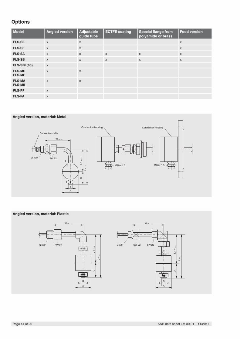
Options
Connection cable
Connection housingConnection housing
L 1
= ...
L =
...U
BA
M20 x 1.5 M20 x 1.5
SW 22G 3/8"
W = ...
L 1
= ...
L =
...
B
L 1
= ...
L =
...
SW 22G 3/8"
A
U
SW 22SW 22 G 3/8"
W = ...
B
A
U
W = ...
Angled version, material: Plastic
Angled version, material: Metal
Model Angled version Adjustable guide tube
ECTFE coating Special flange from polyamide or brass
Food version
FLS-SE x x x
FLS-SF x x xFLS-SA x x x x xFLS-SB x x x x xFLS-SBI (60) xFLS-MEFLS-MF
x x
FLS-MAFLS-MB
x x
FLS-PF xFLS-PA x
Page 14 of 20 KSR data sheet LM 30.01 ∙ 11/2017
A
KB
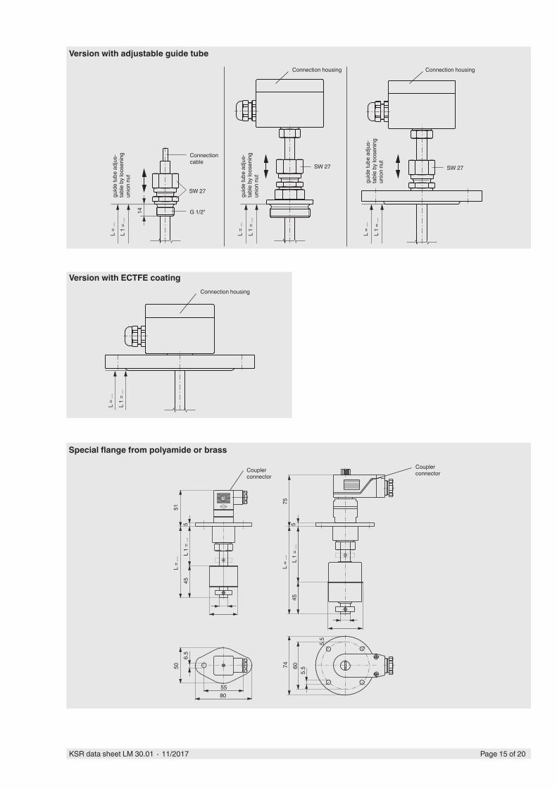
Version with adjustable guide tube
Version with ECTFE coating
Coupler connectorCoupler
connector
L 1
= ...
L =
...
6074
51
5.5
575
45
5L
1 =
...L
= ...
4550
6.5
55
5.5
80
Special flange from polyamide or brass
Page 15 of 20KSR data sheet LM 30.01 ∙ 11/2017
Connection housing
L 1
= ...
L =
...
Connection cable
L 1
= ...
L =
...
L 1
= ...
L =
...
L 1
= ...
L =
...
14
SW 27
G 1/2"
guid
e tu
be a
djus
-ta
ble
by lo
osen
ing
unio
n nu
t
SW 27
guid
e tu
be a
djus
-ta
ble
by lo
osen
ing
unio
n nu
t
guid
e tu
be a
djus
-ta
ble
by lo
osen
ing
unio
n nu
t
SW 27
Connection housing Connection housing
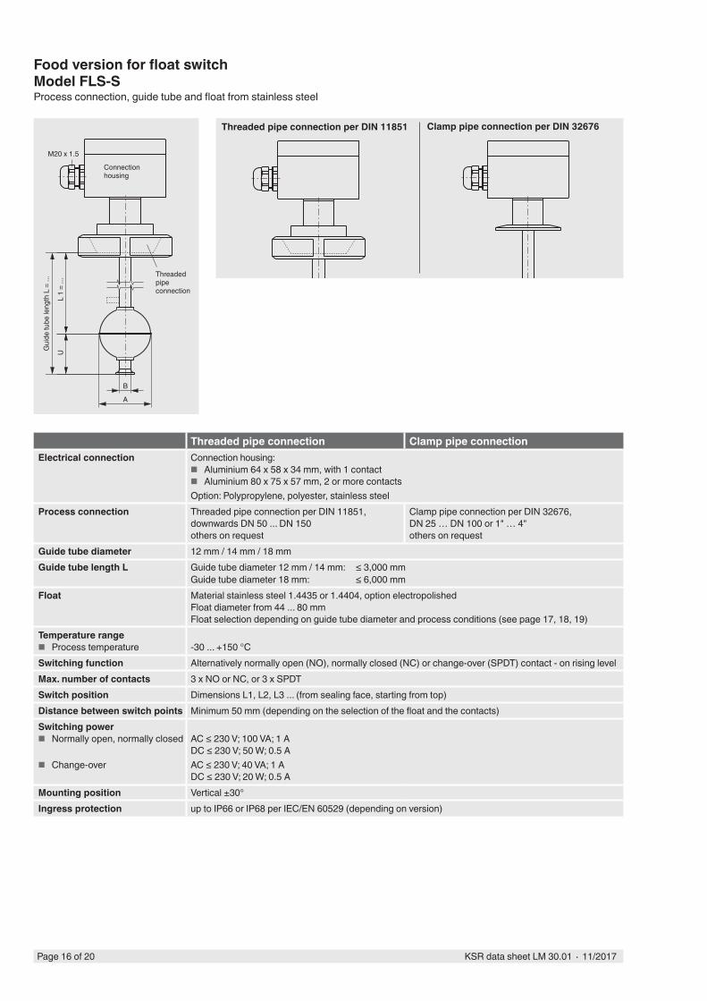
Food version for float switch Model FLS-SProcess connection, guide tube and float from stainless steel
Connection housing
Threaded pipe connection
Gui
de tu
be le
ngth
L =
...
L 1
= ...
B
A
M20 x 1.5
Threaded pipe connection per DIN 11851 Clamp pipe connection per DIN 32676
Threaded pipe connection Clamp pipe connectionElectrical connection Connection housing:
■ Aluminium 64 x 58 x 34 mm, with 1 contact ■ Aluminium 80 x 75 x 57 mm, 2 or more contacts
Option: Polypropylene, polyester, stainless steelProcess connection Threaded pipe connection per DIN 11851,
downwards DN 50 ... DN 150others on request
Clamp pipe connection per DIN 32676, DN 25 … DN 100 or 1" … 4"others on request
Guide tube diameter 12 mm / 14 mm / 18 mmGuide tube length L Guide tube diameter 12 mm / 14 mm: ≤ 3,000 mm
Guide tube diameter 18 mm: ≤ 6,000 mmFloat Material stainless steel 1.4435 or 1.4404, option electropolished
Float diameter from 44 ... 80 mmFloat selection depending on guide tube diameter and process conditions (see page 17, 18, 19)
Temperature range ■ Process temperature -30 ... +150 °C
Switching function Alternatively normally open (NO), normally closed (NC) or change-over (SPDT) contact - on rising levelMax. number of contacts 3 x NO or NC, or 3 x SPDTSwitch position Dimensions L1, L2, L3 ... (from sealing face, starting from top)Distance between switch points Minimum 50 mm (depending on the selection of the float and the contacts)Switching power
■ Normally open, normally closed
■ Change-over
AC ≤ 230 V; 100 VA; 1 ADC ≤ 230 V; 50 W; 0.5 AAC ≤ 230 V; 40 VA; 1 ADC ≤ 230 V; 20 W; 0.5 A
Mounting position Vertical ±30°Ingress protection up to IP66 or IP68 per IEC/EN 60529 (depending on version)
U
Page 16 of 20 KSR data sheet LM 30.01 ∙ 11/2017
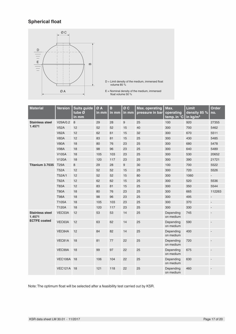
Material Version Suits guide tube Ø in mm
Ø Ain mm
Bin mm
Ø Cin mm
Max. operating pressure in bar
Max. operating temp. in °C
Limit density 85 % in kg/m3
Order no.
Stainless steel 1.4571
V29A/0.2 8 29 28 9 25 100 920 27355V52A 12 52 52 15 40 300 700 5462V62A 12 62 61 15 32 300 670 5511V83A 12 83 81 15 25 300 430 5485V80A 18 80 76 23 25 300 680 5478V98A 18 98 96 23 25 300 640 5489V105A 18 105 103 23 25 300 530 20652V120A 18 120 117 23 25 300 390 21721
Titanium 3.7035 T29A 8 29 28 9 30 100 700 5522T52A 12 52 52 15 25 300 720 5526T52A/1 12 52 52 15 80 300 1060 -T62A 12 62 62 15 25 300 520 5536T83A 12 83 81 15 25 300 350 5544T80A 18 80 76 23 25 300 665 112263T98A 18 98 96 23 25 300 495 -T105A 18 105 103 23 25 300 370 -T120A 18 120 117 23 25 300 330 -
Stainless steel 1.4571ECTFE coated
VEC53A 12 53 53 14 25 Depending on medium
745 -
VEC63A 12 63 62 14 25 Depending on medium
590 -
VEC84A 12 84 82 14 25 Depending on medium
400 -
VEC81A 18 81 77 22 25 Depending on medium
720 -
VEC99A 18 99 97 22 25 Depending on medium
675 -
VEC106A 18 106 104 22 25 Depending on medium
630 -
VEC121A 18 121 118 22 25 Depending on medium
460 -
D = Limit density of the medium, immersed float volume 85 %
E = Nominal density of the medium, immersed float volume 50 %
Ø A
Ø C
D
E B
Spherical float
Note: The optimum float will be selected after a feasibility test carried out by KSR.
Page 17 of 20KSR data sheet LM 30.01 ∙ 11/2017
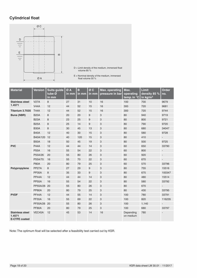
Cylindrical float
D = Limit density of the medium, immersed float volume 85 %
E = Nominal density of the medium, immersed float volume 50 %
Ø C
D
E
B
Ø A
Material Version Suits guide tube Ø in mm
Ø Ain mm
Bin mm
Ø Cin mm
Max. operating pressure in bar
Max. operating temp. in °C
Limit density 85 % in kg/m3
Order no.
Stainless steel 1.4571
V27A 8 27 31 10 16 100 700 9679V44A 12 44 52 15 16 300 720 9681
Titanium 3.7035 T44A 12 44 52 15 16 300 720 9744Buna (NBR) B20A 8 20 20 9 3 80 940 9719
B23A 8 23 25 9 3 80 800 9721B25A 8 25 14 9 3 80 790 9720B30A 8 30 45 13 3 80 680 34047B40A 12 40 30 15 3 80 580 9728B40A/120 12 40 120 15 3 80 410 -B50A 18 50 45 19 3 80 500 9725
PVC P44A 12 44 44 14 3 60 650 33790P55A 16 55 54 22 3 60 800 -P55A/26 20 55 80 26 3 60 920 -P55A/70 16 55 70 22 3 60 670 -P80A 20 80 79 25 3 60 570 33796
Polypropylene PP27A 8 27 29 9 3 80 755 15516PP35A 8 35 33 9 3 80 675 100347PP44A 12 44 44 14 3 80 480 15514PP55A 16 55 54 22 3 80 580 33792PP55A/26 20 55 80 26 3 80 670 -PP80A 20 80 79 25 3 80 430 33795
PVDF PF44A 12 44 55 14 3 100 780 33791PF55A 16 55 69 22 3 100 820 116235PF55A/26 20 55 80 26 3 100 1,140 -PF80A 20 80 79 25 3 100 680 33797
Stainless steel 1.4571E-CTFE coated
VEC45A 12 45 53 14 16 Depending on medium
780 -
Note: The optimum float will be selected after a feasibility test carried out by KSR.
Page 18 of 20 KSR data sheet LM 30.01 ∙ 11/2017
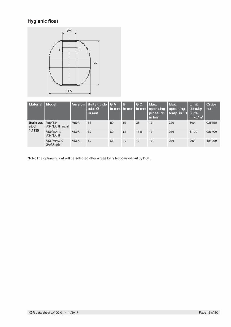
Material Model Version Suits guide tube Ø in mm
Ø Ain mm
Bin mm
Ø Cin mm
Max. operating pressure in bar
Max. operating temp. in °C
Limit density 85 % in kg/m3
Order no.
Stainless steel 1.4435
V80/88/A34/3A/35, axial
V80A 18 80 55 23 16 250 800 025755
V50/55/17/A34/3A/35
V50A 12 50 55 16.8 16 250 1,100 026400
V55/70/A34/3A/35 axial
V55A 12 55 70 17 16 250 900 124069
Hygienic float
Ø A
Ø C
B
Note: The optimum float will be selected after a feasibility test carried out by KSR.
Page 19 of 20KSR data sheet LM 30.01 ∙ 11/2017
KSR KUEBLER Niveau-Messtechnik AGHeinrich-Kuebler-Platz 169439 Zwingenberg/GermanyTel. +49 6263/87-0Fax +49 6263/[email protected]
A division of the WIKA group
Ordering informationTo order the described product the order number (if available) is sufficient.
Alternatively:Model / Version / Electrical connection / Process connection / Guide tube diameter / Guide tube length L / Information about contact (switching function, number of switch points, switch position) / Process specifications (operating temperature and pressure, limit density) / Options
AC 24 ... 230 VR
S1
CDC 24 ... 250 V
S1+
–PLC
S1 RS
C1+
–
DC 24 V
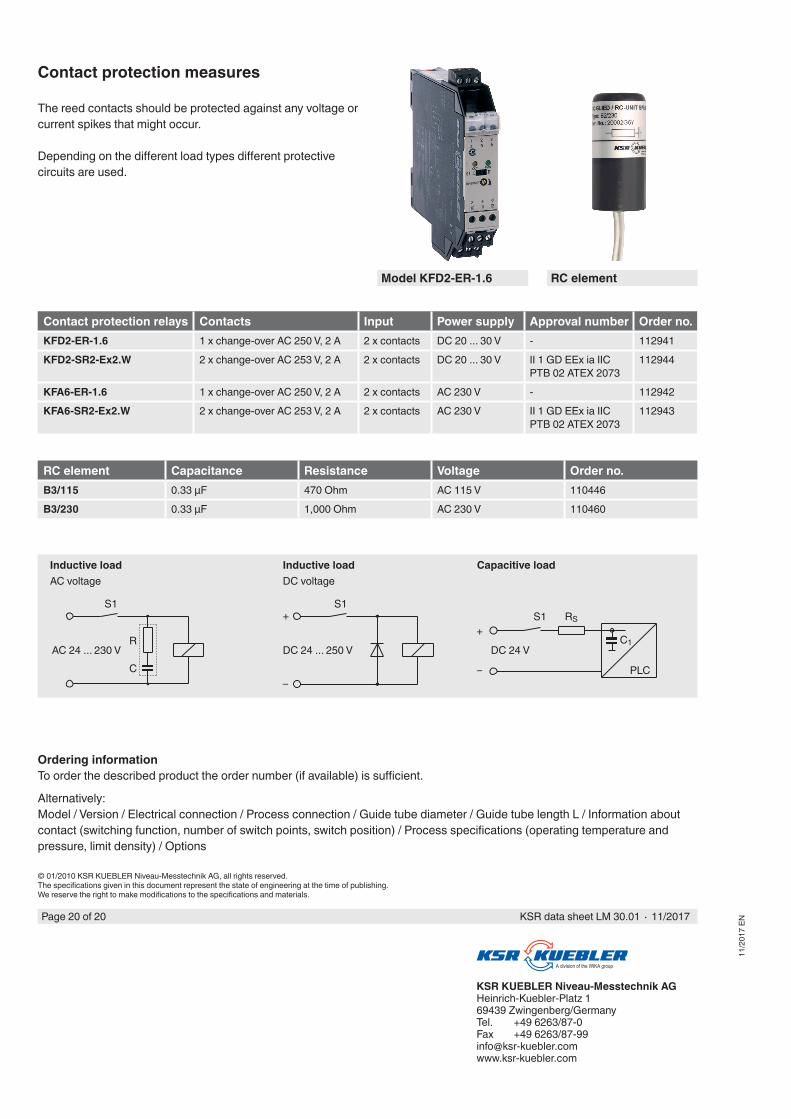
Inductive loadAC voltage
Inductive loadDC voltage
Capacitive load
RC element Capacitance Resistance Voltage Order no.B3/115 0.33 µF 470 Ohm AC 115 V 110446B3/230 0.33 µF 1,000 Ohm AC 230 V 110460
© 01/2010 KSR KUEBLER Niveau-Messtechnik AG, all rights reserved.The specifications given in this document represent the state of engineering at the time of publishing.We reserve the right to make modifications to the specifications and materials.
Contact protection measures
The reed contacts should be protected against any voltage or current spikes that might occur.
Depending on the different load types different protective circuits are used.
Contact protection relays Contacts Input Power supply Approval number Order no.KFD2-ER-1.6 1 x change-over AC 250 V, 2 A 2 x contacts DC 20 ... 30 V - 112941KFD2-SR2-Ex2.W 2 x change-over AC 253 V, 2 A 2 x contacts DC 20 ... 30 V II 1 GD EEx ia IIC
PTB 02 ATEX 2073112944
KFA6-ER-1.6 1 x change-over AC 250 V, 2 A 2 x contacts AC 230 V - 112942KFA6-SR2-Ex2.W 2 x change-over AC 253 V, 2 A 2 x contacts AC 230 V II 1 GD EEx ia IIC
PTB 02 ATEX 2073112943
11/2
017
EN
Page 20 of 20 KSR data sheet LM 30.01 ∙ 11/2017
Model KFD2-ER-1.6 RC element