Embed Size (px)
DESCRIPTION
Refference floating water intake system and how it's work. So, any people can imagine the floating intake system work and to help design intake water.
Citation preview
AN ECONOMICAL AN ECONOMICAL RIVER INTAKE PUMP RIVER INTAKE PUMP
STATIONSTATION
By: Walter T. Winn, Jr., P.E., DWRE, BCEE, F.ASCEBy: Walter T. Winn, Jr., P.E., DWRE, BCEE, F.ASCEGina R. Bolton, P.E., M.ASCEGina R. Bolton, P.E., M.ASCE
Northeast Texas Section WEAT Biennial SeminarNortheast Texas Section WEAT Biennial SeminarLongview, TexasLongview, Texas
OverviewOverview
IntroductionIntroduction Water SupplyWater Supply Intake ConstraintsIntake Constraints Unconventional Intake DesignUnconventional Intake Design Modifications to Design after Construction Modifications to Design after Construction
SubmittalsSubmittals Resolution of Operational IssuesResolution of Operational Issues ConclusionsConclusions
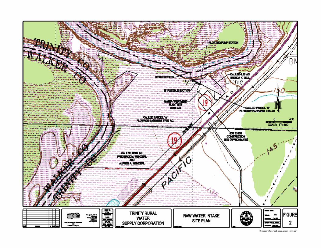
Trinity Rural Water Supply Trinity Rural Water Supply CorporationCorporation
Located in Trinity, Polk, and Walker CountiesLocated in Trinity, Polk, and Walker Counties Serves approximately 1,400 customersServes approximately 1,400 customers System previously served by ground water and System previously served by ground water and
purchased water from Trinity River Authority purchased water from Trinity River Authority (TRA) Trinity Co. Regional System and the City (TRA) Trinity Co. Regional System and the City of Trinityof Trinity
Additional water not available from TRA Additional water not available from TRA Regional System & Trinity. No groundwater of Regional System & Trinity. No groundwater of acceptable quality and quantity.acceptable quality and quantity.
New Source of SupplyNew Source of Supply
Water rights from Lake Livingston owned by Water rights from Lake Livingston owned by TRA and reserved for local useTRA and reserved for local use
Raw water from Trinity River at headwaters of Raw water from Trinity River at headwaters of Lake LivingstonLake Livingston
Plant site located 1Plant site located 1--½½ mile north of SH 19 mile north of SH 19 crossing of the Trinity River, west of SH 19crossing of the Trinity River, west of SH 19
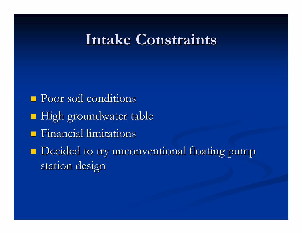
Intake ConstraintsIntake Constraints
Poor soil conditionsPoor soil conditions High groundwater tableHigh groundwater table Financial limitationsFinancial limitations Decided to try unconventional floating pump Decided to try unconventional floating pump
station designstation design
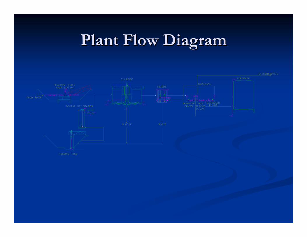
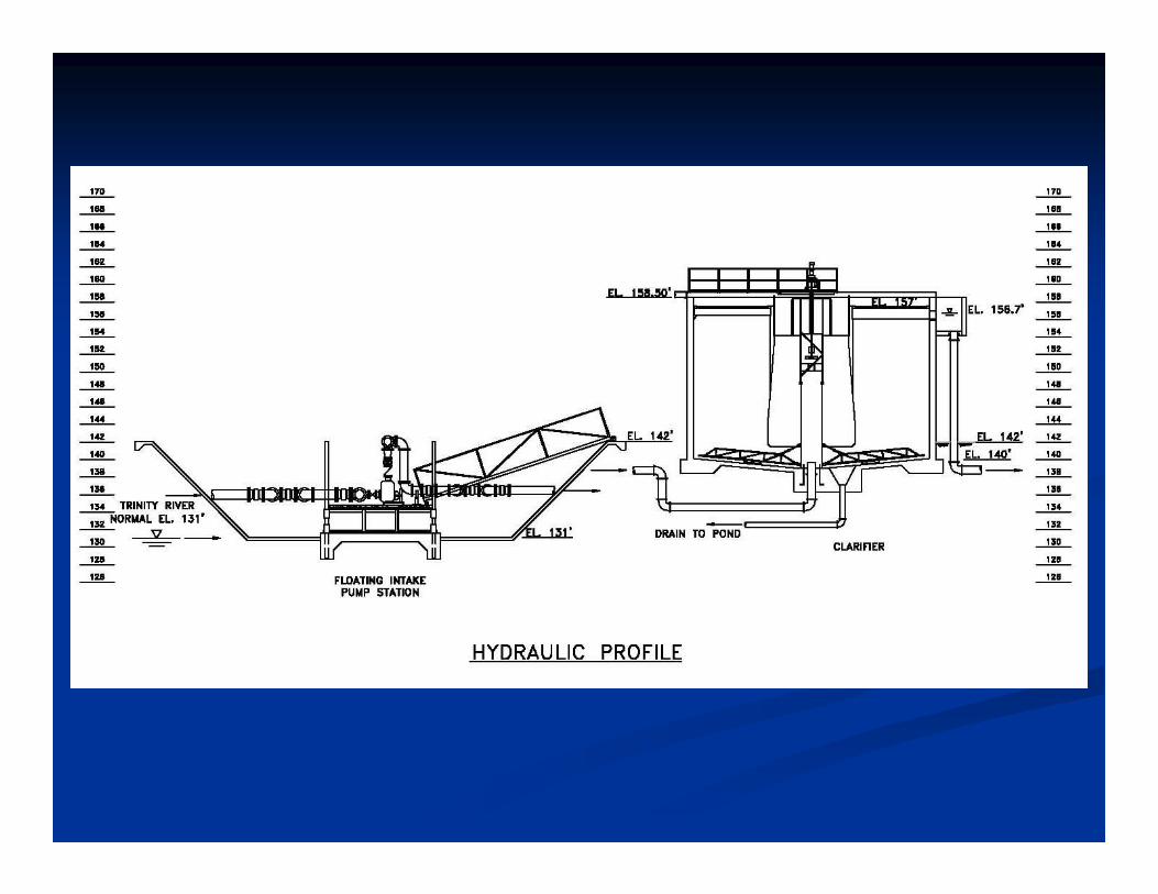
Plant Flow DiagramPlant Flow Diagram
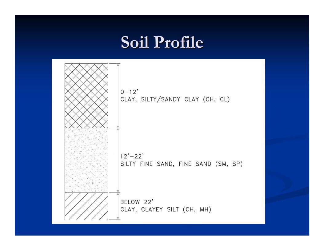
Soil ProfileSoil Profile
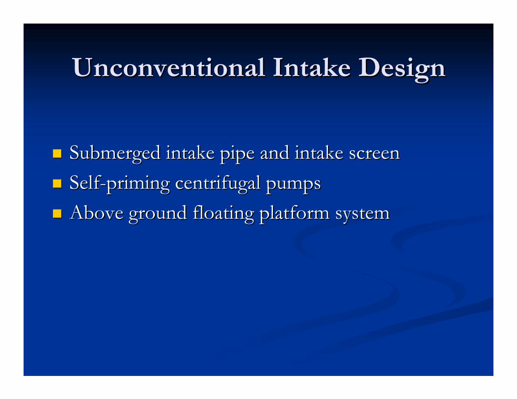
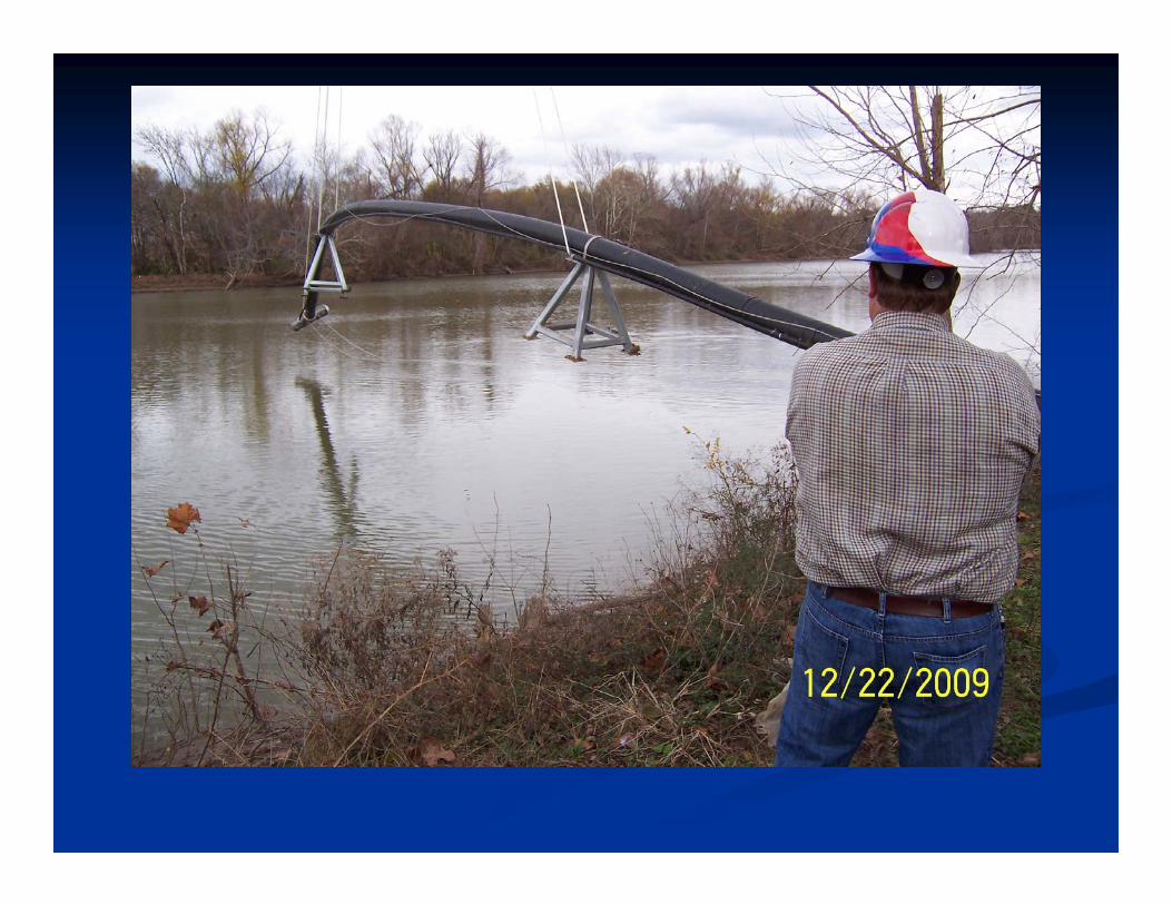
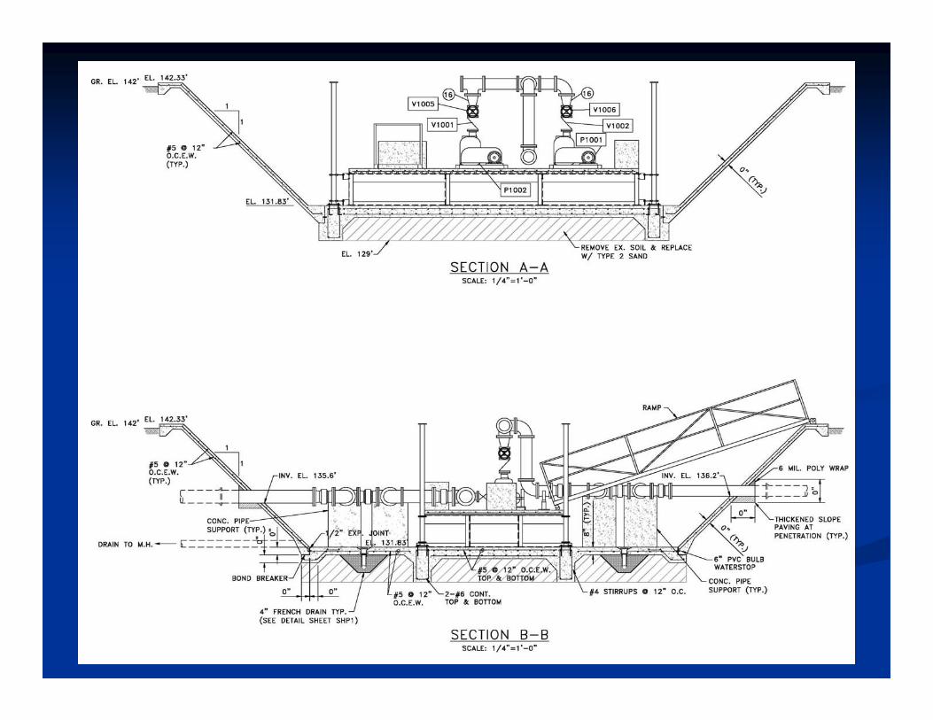
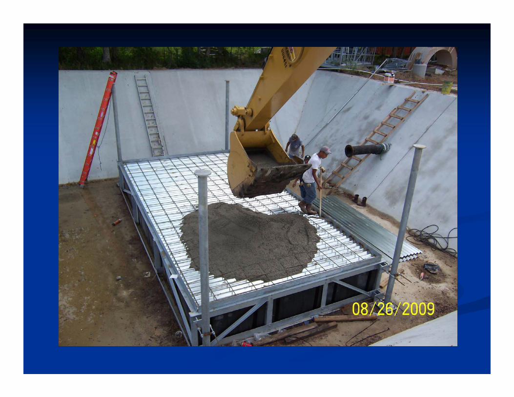
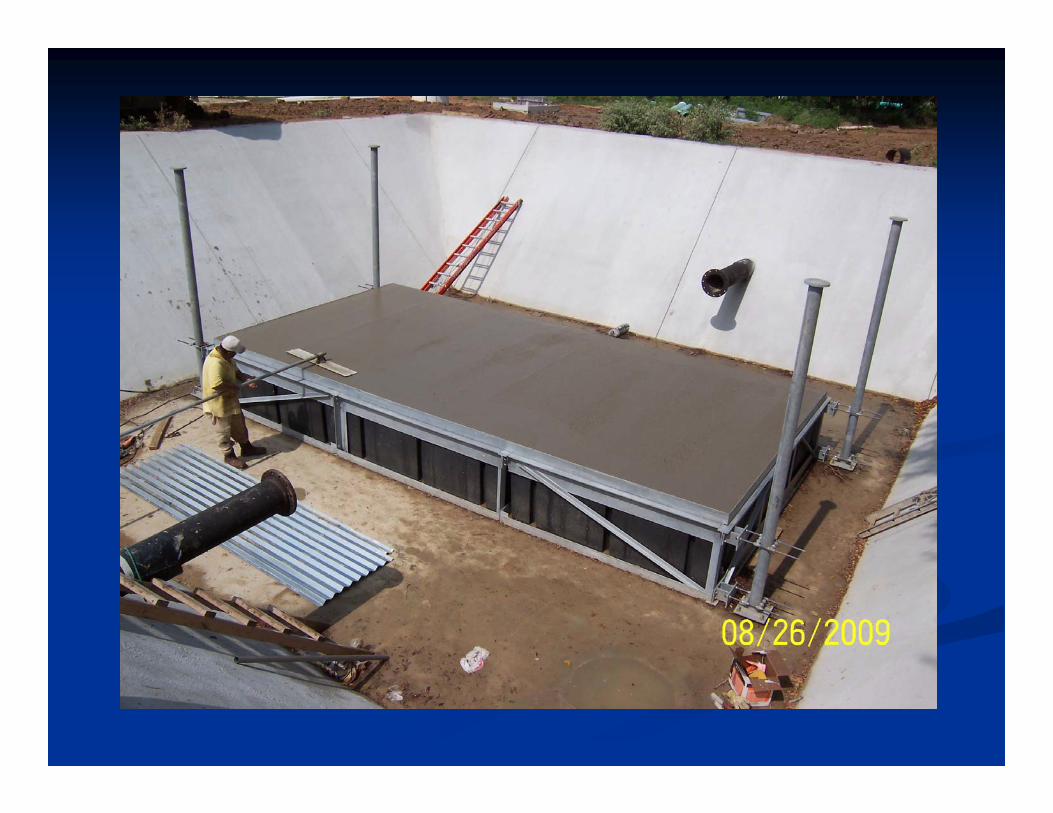
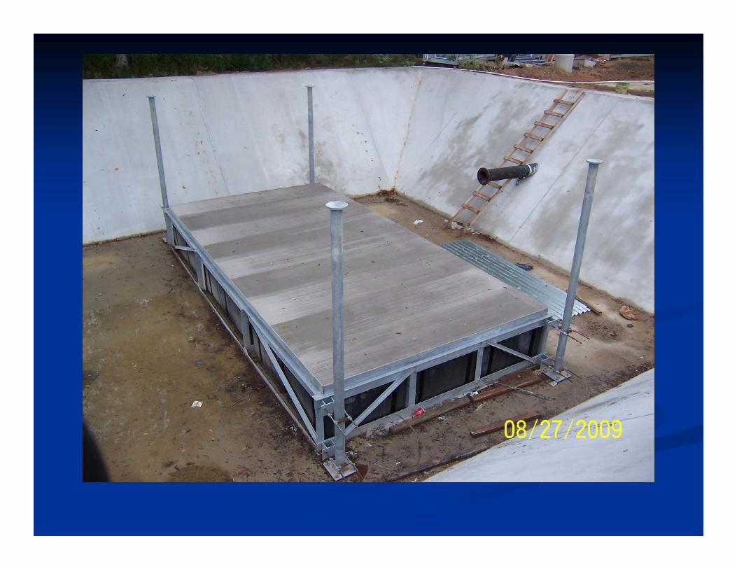
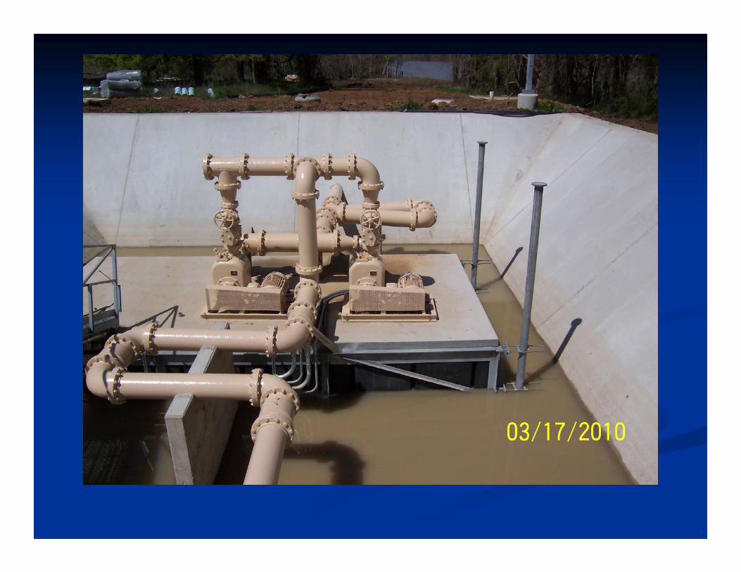
Unconventional Intake DesignUnconventional Intake Design
Submerged intake pipe and intake screenSubmerged intake pipe and intake screen SelfSelf--priming centrifugal pumps priming centrifugal pumps Above ground floating platform systemAbove ground floating platform system
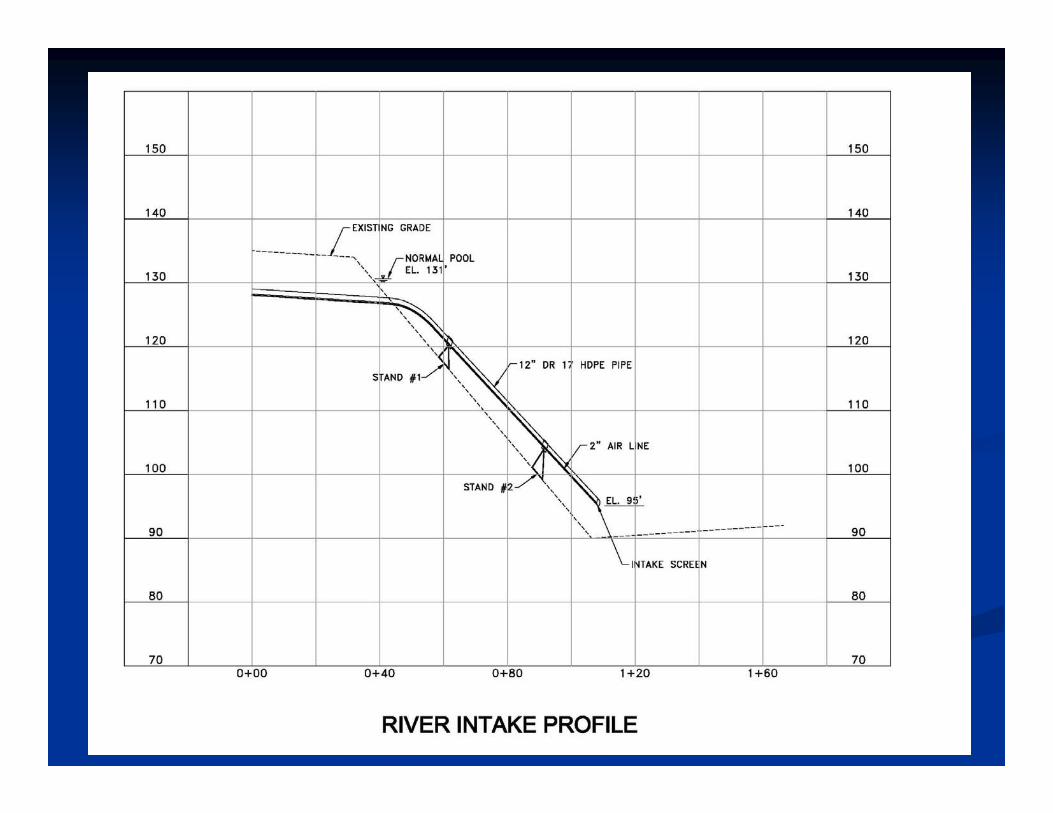
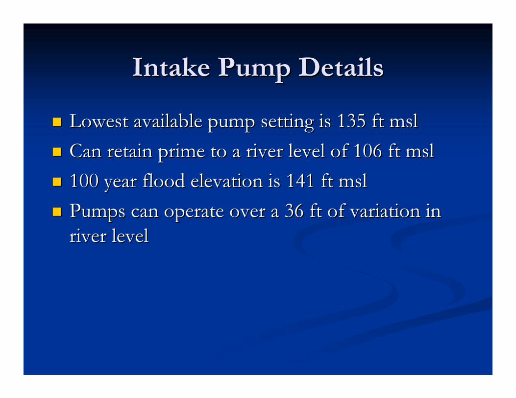
Intake Pump DetailsIntake Pump Details
Lowest available pump setting is 135 ft mslLowest available pump setting is 135 ft msl Can retain prime to a river level of 106 ft mslCan retain prime to a river level of 106 ft msl 100 year flood elevation is 141 ft msl100 year flood elevation is 141 ft msl Pumps can operate over a 36 ft of variation in Pumps can operate over a 36 ft of variation in
river levelriver level
Modifications to Design After Modifications to Design After Construction SubmittalsConstruction Submittals
The pumps selected by Contractor were The pumps selected by Contractor were significantly heavier than the originally specified significantly heavier than the originally specified pumpspumps
Concrete slab on platform was modified to use Concrete slab on platform was modified to use light weight concrete and reduce slab thickness light weight concrete and reduce slab thickness from 6from 6”” to 5to 5””..
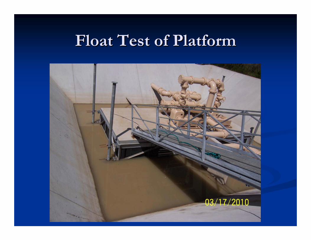
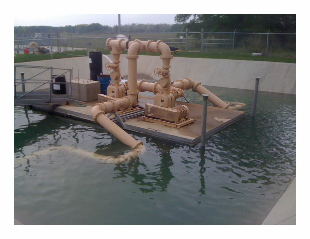
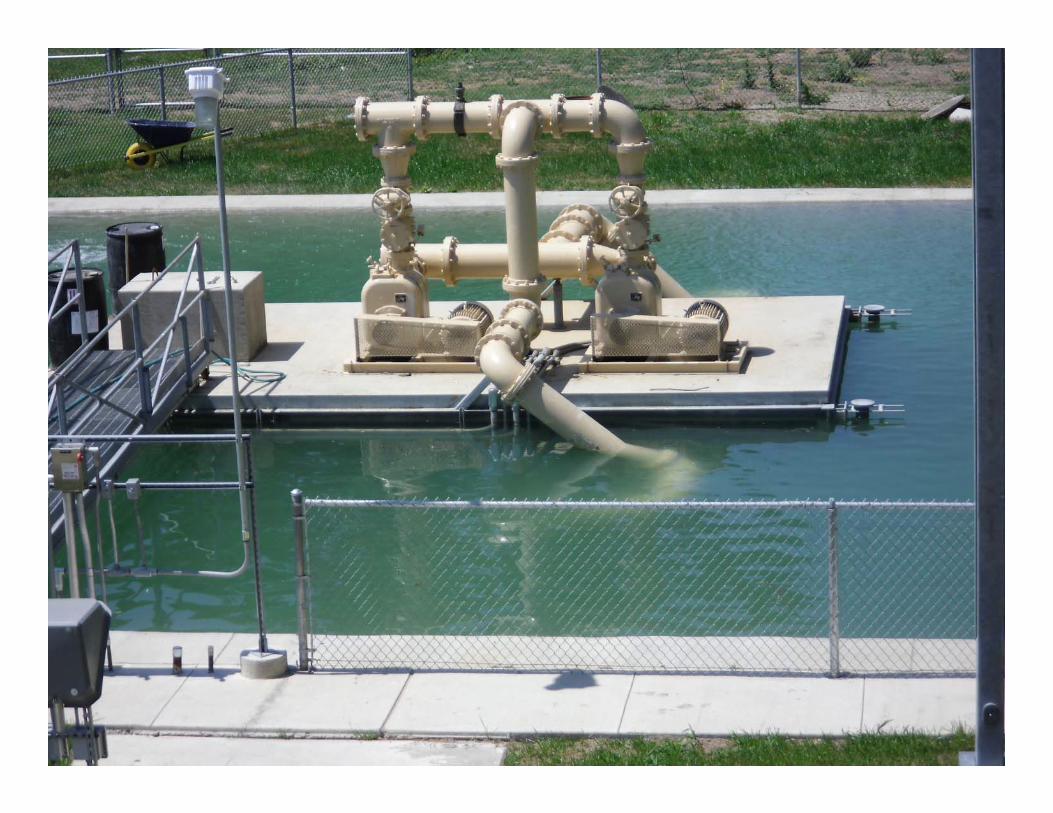
Float Test of PlatformFloat Test of Platform
Problems Discovered in TestingProblems Discovered in Testing
Platform twisting, putting torque on the posts Platform twisting, putting torque on the posts and pipe rollers holding it in place.and pipe rollers holding it in place.
Platform was not level as it was tilting towards Platform was not level as it was tilting towards the corner where the pumps were placed. the corner where the pumps were placed.
Therefore, the weight was not evenly distributed Therefore, the weight was not evenly distributed across the platform.across the platform.
Back to the drawing board.Back to the drawing board.
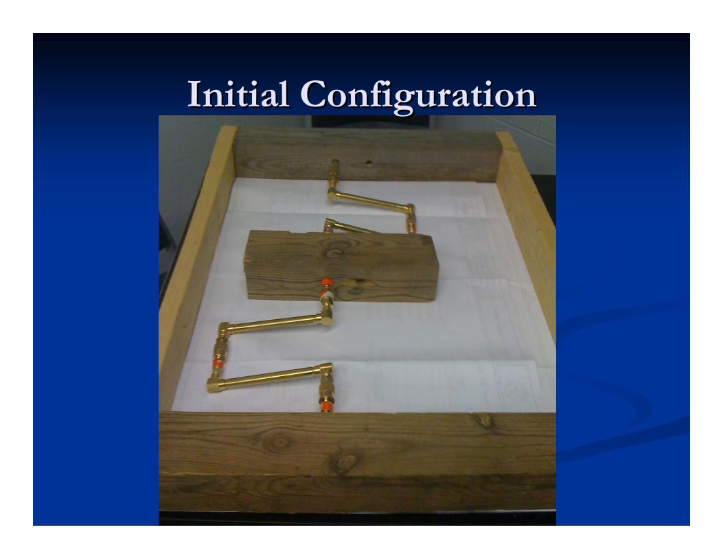
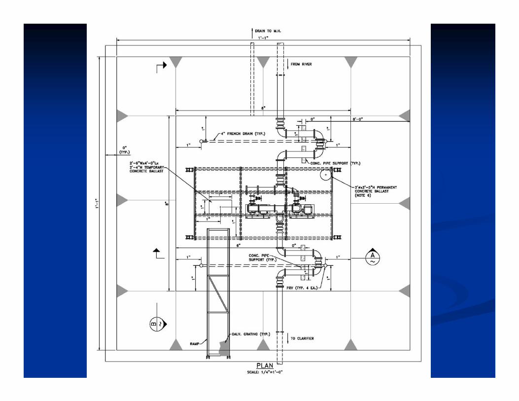
Initial ConfigurationInitial Configuration
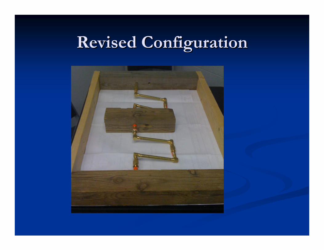
Revised ConfigurationRevised Configuration
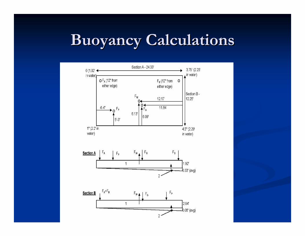
Buoyancy CalculationsBuoyancy Calculations
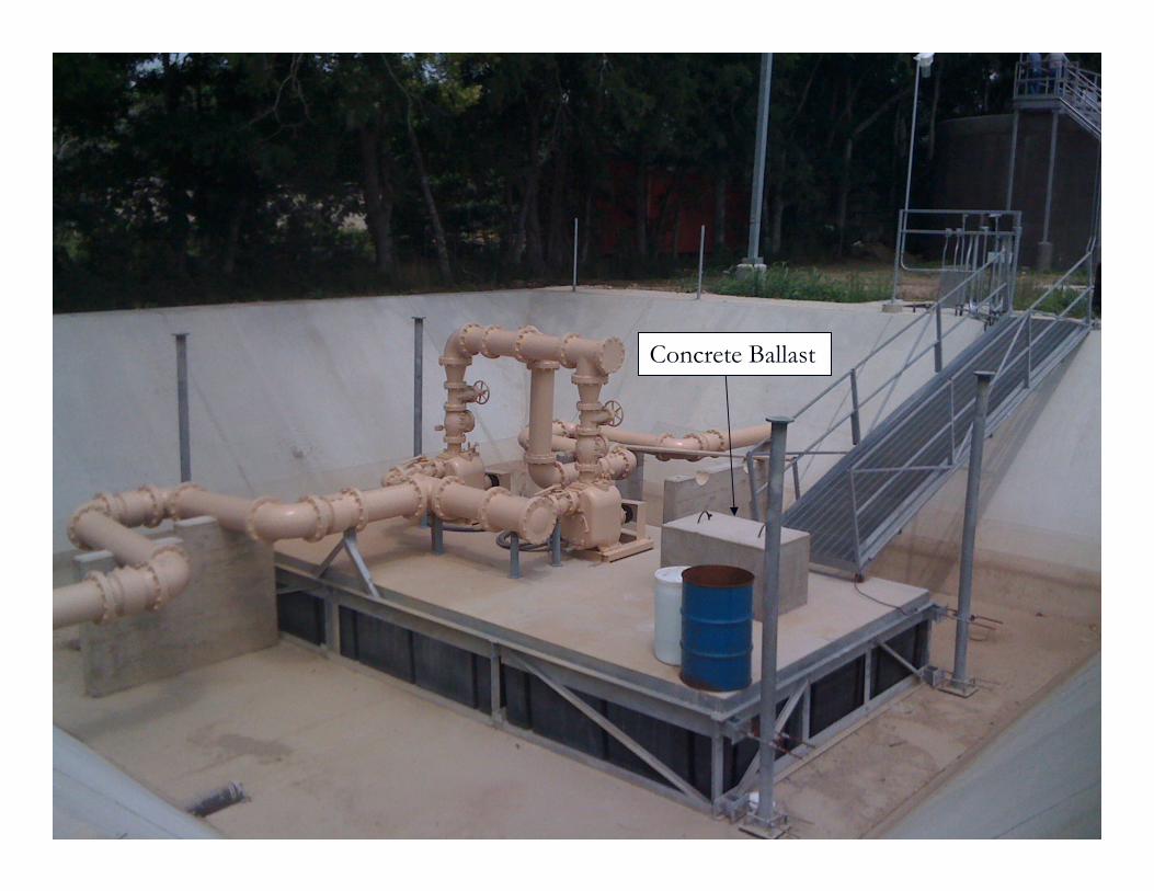
Concrete Ballast
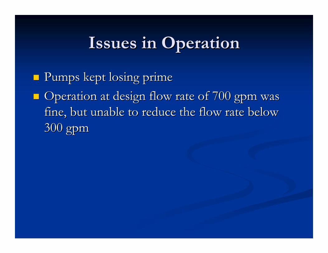
Issues in OperationIssues in Operation
Pumps kept losing prime Pumps kept losing prime Operation at design flow rate of 700 gpm was Operation at design flow rate of 700 gpm was
fine, but unable to reduce the flow rate below fine, but unable to reduce the flow rate below 300 gpm300 gpm
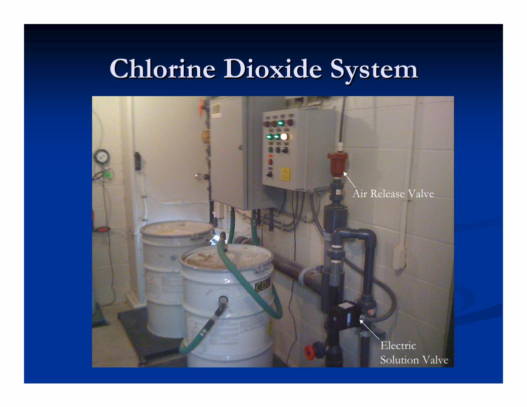
Chlorine Dioxide SystemChlorine Dioxide System
Air Release Valve
Electric Solution Valve
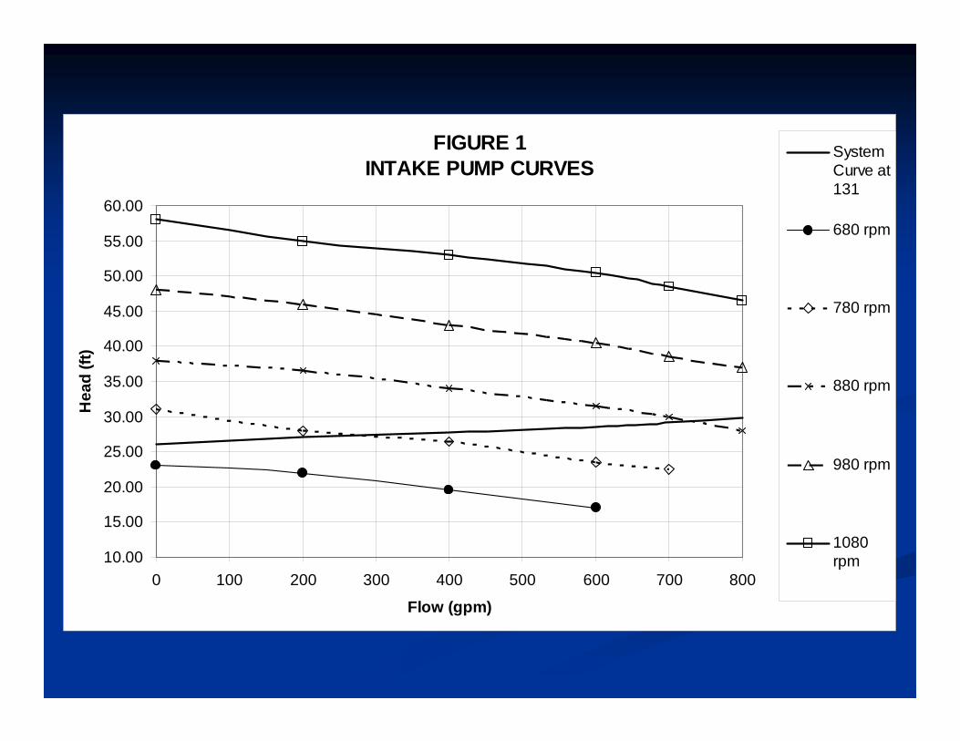
FIGURE 1 INTAKE PUMP CURVES
10.00
15.00
20.00
25.00
30.00
35.00
40.00
45.00
50.00
55.00
60.00
0 100 200 300 400 500 600 700 800
Flow (gpm)
Hea
d (ft
)
SystemCurve at131
680 rpm
780 rpm
880 rpm
980 rpm
1080rpm
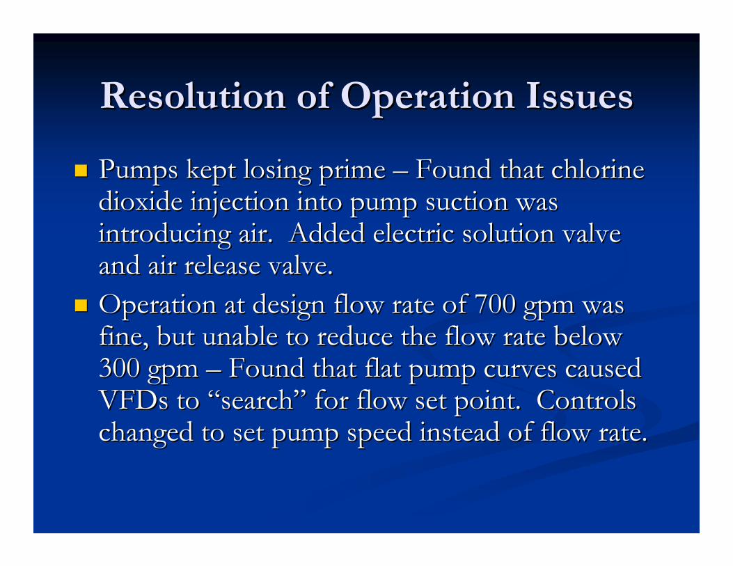
Resolution of Operation IssuesResolution of Operation Issues
Pumps kept losing prime Pumps kept losing prime –– Found that chlorine Found that chlorine dioxide injection into pump suction was dioxide injection into pump suction was introducing air. Added electric solution valve introducing air. Added electric solution valve and air release valve.and air release valve.
Operation at design flow rate of 700 gpm was Operation at design flow rate of 700 gpm was fine, but unable to reduce the flow rate below fine, but unable to reduce the flow rate below 300 gpm 300 gpm –– Found that flat pump curves caused Found that flat pump curves caused VFDs to VFDs to ““searchsearch”” for flow set point. Controls for flow set point. Controls changed to set pump speed instead of flow rate.changed to set pump speed instead of flow rate.
ConclusionsConclusions
Worked through issues to develop Worked through issues to develop unconventional river intake pump station.unconventional river intake pump station.
Saved Trinity Rural WSC an estimated $650,000, Saved Trinity Rural WSC an estimated $650,000, about 65% of the original estimated intake about 65% of the original estimated intake pump station cost.pump station cost.

Questions?Questions?