Embed Size (px)
Citation preview
27 February 2014 Motion Imagery Standards Board 1
1 Scope
This Standard describes the method for mapping floating point values to integer values and the
reverse, mapping integer values back to their original floating point value to within an acceptable
precision. There are many ways of optimizing the transmission of floating point values from one
system to another; the purpose of this Standard is to provide a single method which can be used
for all floating point ranges and valid precisions. This Standard provides a method for a forward
and reverse linear mapping of a specified range of floating point values to a specified integer
range of values based on the number of bytes desired to be used for the integer value.
Additionally it provides a set of special values which can be used to transmit non-numerical
“signals” to a receiving system.
2 References
2.1 Normative References
The following references and the references contained therein are normative.
[1] IEEE 754-2008, Standard for Floating-Point Arithmetic [and Floating-Point formats]
2.2 Informative References
N/A
3 Terms and Definitions
Ceiling
Defined as rounding any non-integer value up toward +∞. The notation used is ⌈𝑥⌉ and the
ceiling function is defined as: ⌈𝑥⌉ = min{𝑛 ∈ ℤ|𝑛 ≥ 𝑥}. Examples: ⌈−1.1⌉ = −1; ⌈1.1⌉ = 2.
Note: Microsoft Excel (pre 2010) does not perform this operation correctly.
Floor
Defined as rounding any non-integer value down towards -∞. The notation used is ⌊𝑥⌋ and
the floor function is defined as: ⌊𝑥⌋ = max{𝑚 ∈ ℤ|𝑚 ≤ 𝑥}. Examples: ⌊−1.1⌋ = −2; ⌊1.1⌋ = 1. Note: Microsoft Excel (pre 2010) does not perform this operation correctly.
STANDARD Floating Point to Integer Mapping
MISB ST 1201.1
February 27 2014
ST 1201.1 - Floating Point to Integer Mapping
27 February 2014 Motion Imagery Standards Board 2
Truncate
A function that removes the fractional part of a real number (e.g. truncate (100.2) = 100).
Round
A function has different modes but for this standard round means ⌊𝑥 + 0.5⌋ if x≥0 and ⌈𝑥 − 0.5⌉ if x<0.
4 Revision History
Revision Date Summary of Changes
ST 1201.1 02/27/2014 Promoted to Standard
5 Introduction - Informative
Many data values that are measured or computed in floating point are inserted into KLV for
transmission between systems. Oftentimes, values do not fully utilize the floating point range or
precision afforded, and thus there is opportunity to reduce the number of bytes used to represent
the data. Additionally, there are special cases in measurements and computations that need to be
communicated; for example, a sensor value that means “beyond measurement range” or during a
computation a divide by zero occurs (i.e. +infinity). This Standard applies to IEEE 754 floating
point values (all precisions; i.e. 16, 32, 64 and 128 bit), including many of the IEEE special
values of infinity, and NaN’s.
In Section 7 of this document the standard algorithm is succinctly stated for developers to
implement; Section 8 of this document is informative and shows the derivation of the algorithm
and format.
6 Algorithm Requirements
To aid understanding some of the steps in the standard mapping described below, the
requirements for the algorithm are as follows:
Requirement
ST 1201.1-01 The binary representation of a floating point value shall be in the format of an IEEE 754-2008 floating point value.
ST 1201.1-02 The algorithm shall perform the mapping based on a [user] specified floating point range from a min value to a max value – inclusive (including the end points).
ST 1201.1-03 The algorithm shall be a linear mapping from a floating point value to a non-negative integer value of [user] defined length in bytes.
ST 1201.1-04 The binary representation of a non-negative integer value shall be in the format of a standard unsigned integer, with the length, in bytes, defined by the [user’s] implementing standard.
ST 1201.1-05 The algorithm shall provide an inverse mapping from a non-negative integer value to the original floating point value within a [user] specified precision. (Note: the mapping algorithm can supply better precision than what the user specifies. The
ST 1201.1 - Floating Point to Integer Mapping
27 February 2014 Motion Imagery Standards Board 3
defined length and precision are related – given one the other can be computed but both cannot be specified by the user).
ST 1201.1-06 If the [users] floating point range includes 0.0, then the algorithm shall map 0.0 exactly to a specific integer value, called a “zero offset”.
ST 1201.1-07 All floating point values that are negative shall map to an integer that is less that the zero offset.
ST 1201.1-08 All values that are positive shall map to values greater than or equal to the zero offset.
ST 1201.1-09 The algorithm shall be designed to be as few operations as possible (during the actual mapping) for computational efficiency.
ST 1201.1-10 The resulting format shall provide a set of special values which map to the IEEE 754-2008 special values, including: ± infinity, ±QNan and ±SNan (note: negative zero is not included in this requirement).
ST 1201.1-11 The resulting format shall provide a bit space for custom signals to be sent by the user as defined by the [users] implementing standard (i.e. local set standard).
7 Standard Mapping Algorithm and Integer Format
This section describes the standard algorithm for mapping the floating point values to integer
values, and the reverse mapping of integers back to floating point values. Additionally, this
section defines the notation to use in all MISB standards when “invoking” this Standard. Section
8 is an informative section which describes the development of this algorithm in detail.
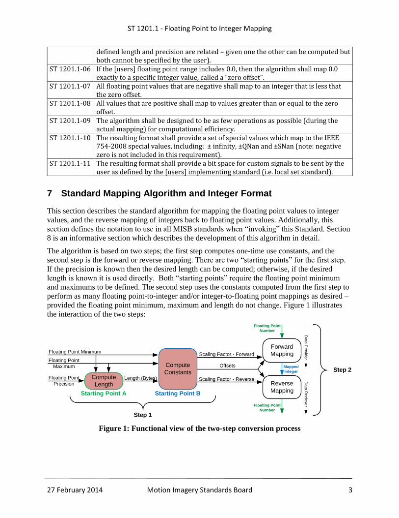
The algorithm is based on two steps; the first step computes one-time use constants, and the
second step is the forward or reverse mapping. There are two “starting points” for the first step.
If the precision is known then the desired length can be computed; otherwise, if the desired
length is known it is used directly. Both “starting points” require the floating point minimum
and maximums to be defined. The second step uses the constants computed from the first step to
perform as many floating point-to-integer and/or integer-to-floating point mappings as desired –
provided the floating point minimum, maximum and length do not change. Figure 1 illustrates
the interaction of the two steps:
Figure 1: Functional view of the two-step conversion process
Compute
Length
Compute
Constants
Floating Point Minimum
Floating Point
Maximum
Floating Point
PrecisionLength (Bytes)
Scaling Factor - Forward
Scaling Factor - Reverse
Offsets
Forward
Mapping
Reverse
Mapping
Floating Point
Number
Mapped
Integer
Floating Point
Number
Step 1
Step 2
Da
ta P
rovid
er
Da
ta R
ecie
ve
r
Starting Point A Starting Point B
ST 1201.1 - Floating Point to Integer Mapping
27 February 2014 Motion Imagery Standards Board 4
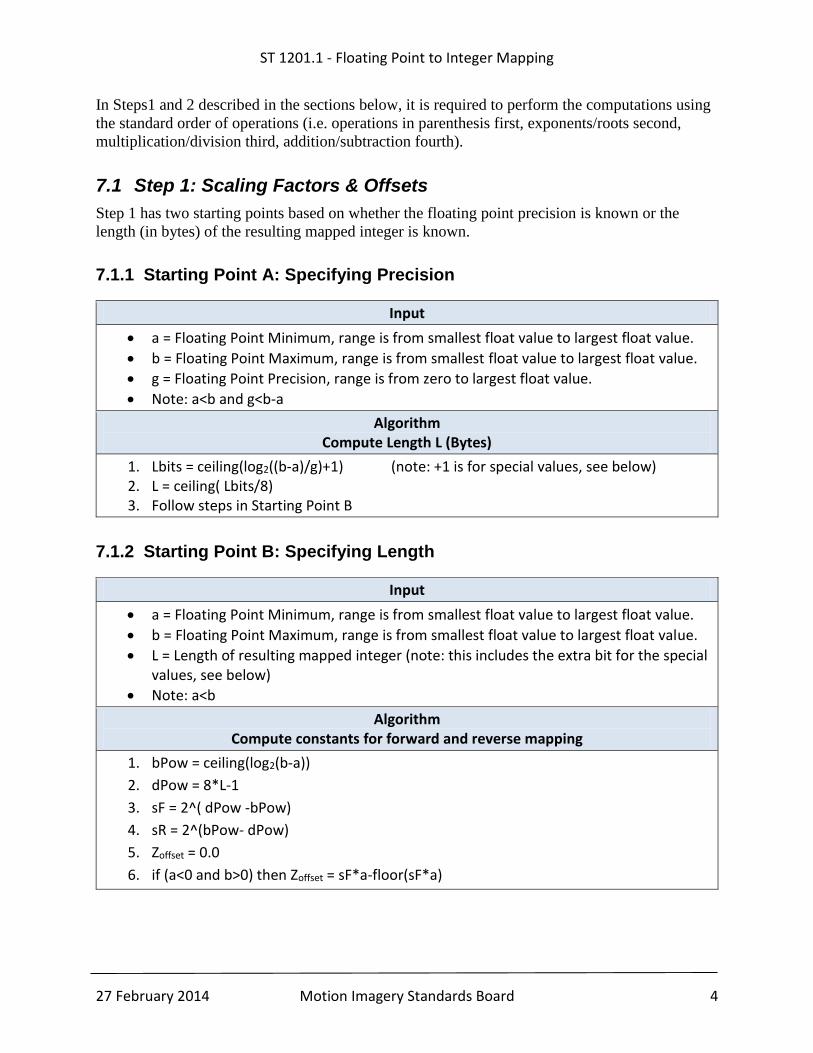
In Steps1 and 2 described in the sections below, it is required to perform the computations using
the standard order of operations (i.e. operations in parenthesis first, exponents/roots second,
multiplication/division third, addition/subtraction fourth).
7.1 Step 1: Scaling Factors & Offsets
Step 1 has two starting points based on whether the floating point precision is known or the
length (in bytes) of the resulting mapped integer is known.
7.1.1 Starting Point A: Specifying Precision
Input
a = Floating Point Minimum, range is from smallest float value to largest float value.
b = Floating Point Maximum, range is from smallest float value to largest float value.
g = Floating Point Precision, range is from zero to largest float value.
Note: a<b and g<b-a
Algorithm Compute Length L (Bytes)
1. Lbits = ceiling(log2((b-a)/g)+1) (note: +1 is for special values, see below) 2. L = ceiling( Lbits/8) 3. Follow steps in Starting Point B
7.1.2 Starting Point B: Specifying Length
Input
a = Floating Point Minimum, range is from smallest float value to largest float value.
b = Floating Point Maximum, range is from smallest float value to largest float value.
L = Length of resulting mapped integer (note: this includes the extra bit for the special values, see below)
Note: a<b
Algorithm Compute constants for forward and reverse mapping
1. bPow = ceiling(log2(b-a))
2. dPow = 8*L-1
3. sF = 2^( dPow -bPow)
4. sR = 2^(bPow- dPow)
5. Zoffset = 0.0
6. if (a<0 and b>0) then Zoffset = sF*a-floor(sF*a)
ST 1201.1 - Floating Point to Integer Mapping
27 February 2014 Motion Imagery Standards Board 5
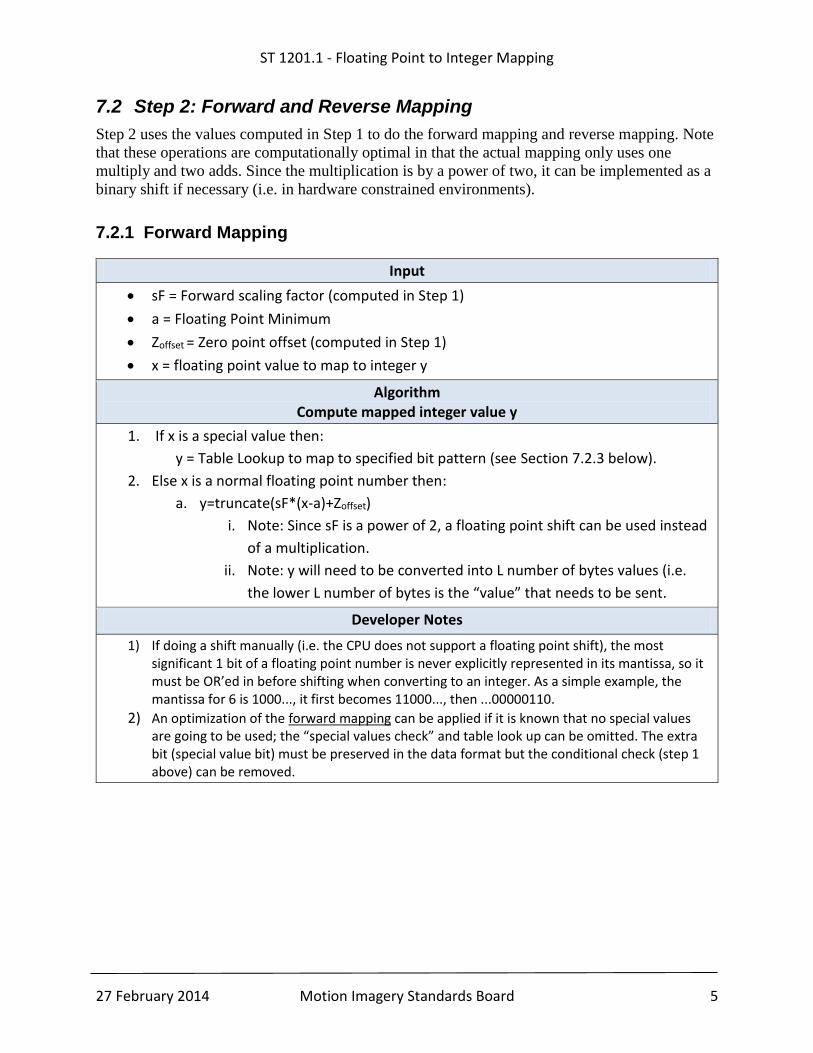
7.2 Step 2: Forward and Reverse Mapping
Step 2 uses the values computed in Step 1 to do the forward mapping and reverse mapping. Note
that these operations are computationally optimal in that the actual mapping only uses one
multiply and two adds. Since the multiplication is by a power of two, it can be implemented as a
binary shift if necessary (i.e. in hardware constrained environments).
7.2.1 Forward Mapping
Input
sF = Forward scaling factor (computed in Step 1)
a = Floating Point Minimum
Zoffset = Zero point offset (computed in Step 1)
x = floating point value to map to integer y
Algorithm Compute mapped integer value y
1. If x is a special value then:
y = Table Lookup to map to specified bit pattern (see Section 7.2.3 below).
2. Else x is a normal floating point number then:
a. y=truncate(sF*(x-a)+Zoffset)
i. Note: Since sF is a power of 2, a floating point shift can be used instead
of a multiplication.
ii. Note: y will need to be converted into L number of bytes values (i.e.
the lower L number of bytes is the “value” that needs to be sent.
Developer Notes
1) If doing a shift manually (i.e. the CPU does not support a floating point shift), the most significant 1 bit of a floating point number is never explicitly represented in its mantissa, so it must be OR’ed in before shifting when converting to an integer. As a simple example, the mantissa for 6 is 1000..., it first becomes 11000..., then ...00000110.
2) An optimization of the forward mapping can be applied if it is known that no special values are going to be used; the “special values check” and table look up can be omitted. The extra bit (special value bit) must be preserved in the data format but the conditional check (step 1 above) can be removed.
ST 1201.1 - Floating Point to Integer Mapping
27 February 2014 Motion Imagery Standards Board 6
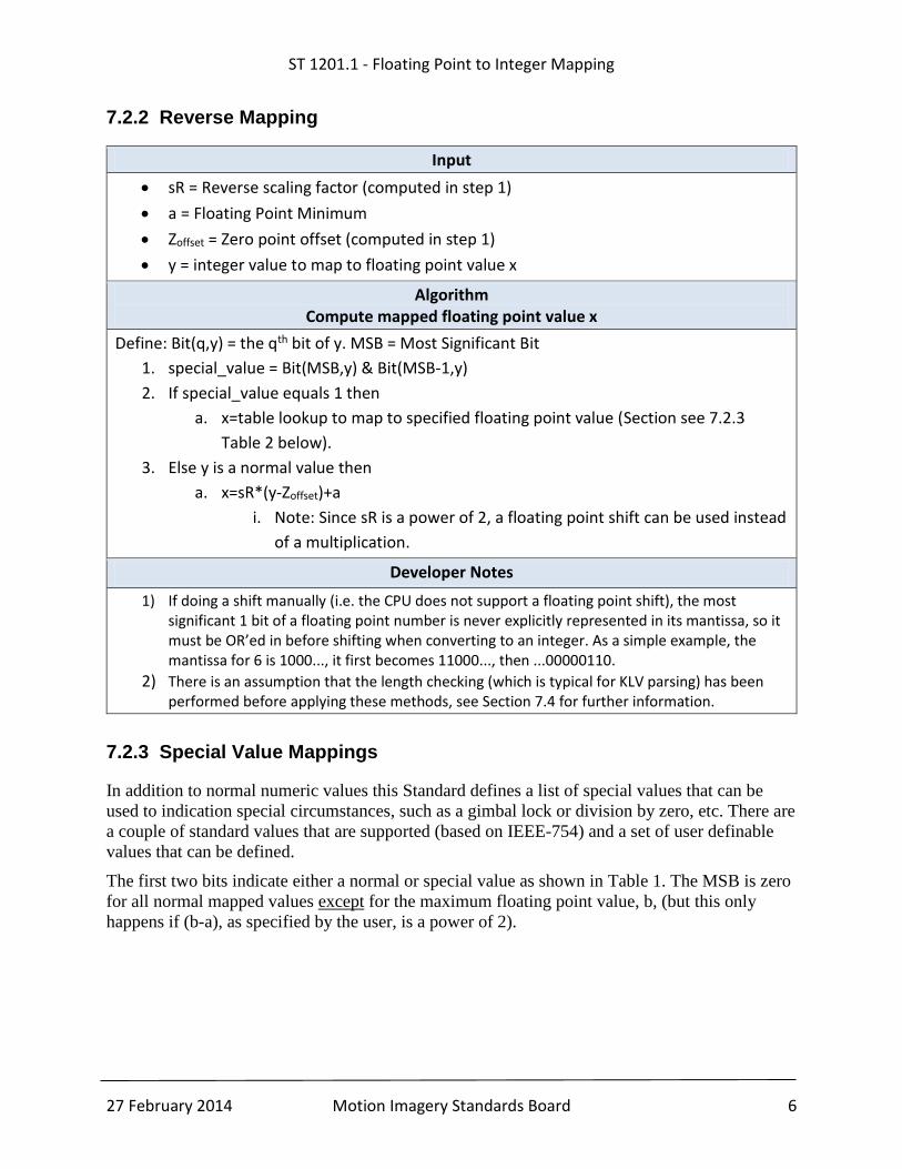
7.2.2 Reverse Mapping
Input
sR = Reverse scaling factor (computed in step 1)
a = Floating Point Minimum
Zoffset = Zero point offset (computed in step 1)
y = integer value to map to floating point value x
Algorithm Compute mapped floating point value x
Define: Bit(q,y) = the qth bit of y. MSB = Most Significant Bit
1. special_value = Bit(MSB,y) & Bit(MSB-1,y)
2. If special_value equals 1 then
a. x=table lookup to map to specified floating point value (Section see 7.2.3
Table 2 below).
3. Else y is a normal value then
a. x=sR*(y-Zoffset)+a
i. Note: Since sR is a power of 2, a floating point shift can be used instead
of a multiplication.
Developer Notes
1) If doing a shift manually (i.e. the CPU does not support a floating point shift), the most significant 1 bit of a floating point number is never explicitly represented in its mantissa, so it must be OR’ed in before shifting when converting to an integer. As a simple example, the mantissa for 6 is 1000..., it first becomes 11000..., then ...00000110.
2) There is an assumption that the length checking (which is typical for KLV parsing) has been performed before applying these methods, see Section 7.4 for further information.
7.2.3 Special Value Mappings
In addition to normal numeric values this Standard defines a list of special values that can be
used to indication special circumstances, such as a gimbal lock or division by zero, etc. There are
a couple of standard values that are supported (based on IEEE-754) and a set of user definable
values that can be defined.
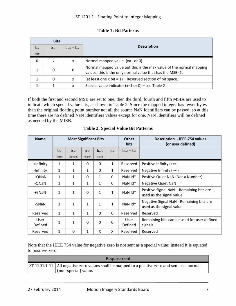
The first two bits indicate either a normal or special value as shown in Table 1. The MSB is zero
for all normal mapped values except for the maximum floating point value, b, (but this only
happens if (b-a), as specified by the user, is a power of 2).
ST 1201.1 - Floating Point to Integer Mapping
27 February 2014 Motion Imagery Standards Board 7
Table 1: Bit Patterns
Bits Description bn
(MSB) bn-1
bn-2 – b0
0 x x Normal mapped value. (x=1 or 0)
1 0 0 Normal mapped value but this is the max value of the normal mapping values; this is the only normal value that has the MSB=1.
1 0 x (at least one x bit = 1) – Reserved section of bit space.
1 1 x Special value indicator (x=1 or 0) – see Table 2
If both the first and second MSB are set to one, then the third, fourth and fifth MSBs are used to
indicate which special value it is, as shown in Table 2. Since the mapped integer has fewer bytes
than the original floating point number not all the source NaN Identifiers can be passed; so at this
time there are no defined NaN Identifiers values except for one. NaN Identifiers will be defined
as needed by the MISB.
Table 2: Special Value Bit Patterns
Name Most Significant Bits Other bits
Description - IEEE-754 values (or user defined)
bn
(MSB) bn-1
(Special) bn-2
(Sign) bn-3
(NaN) bn-4 bn-5 – b0
+Infinity 1 1 0 0 1 Reserved Positive Infinity (+∞)
-Infinity 1 1 1 0 1 Reserved Negative Infinity (-∞)
+QNaN 1 1 0 1 0 NaN Id* Positive Quiet NaN (Not a Number)
-QNaN 1 1 1 1 0 NaN Id* Negative Quiet NaN
+SNaN 1 1 0 1 1 NaN Id* Positive Signal NaN – Remaining bits are used as the signal value.
-SNaN 1 1 1 1 1 NaN Id* Negative Signal NaN - Remaining bits are used as the signal value.
Reserved 1 1 1 0 0 Reserved Reserved
User Defined
1 1 0 0 0 User
Defined Remaining bits can be used for user defined signals
Reserved 1 0 1 X X Reserved Reserved
Note that the IEEE 754 value for negative zero is not sent as a special value; instead it is equated
to positive zero.
Requirement
ST 1201.1-12 All negative zero values shall be mapped to a positive zero and sent as a normal (non-special) value.
ST 1201.1 - Floating Point to Integer Mapping
27 February 2014 Motion Imagery Standards Board 8
In addition to the IEEE bit values a set of user defined bit patterns is available for definition;
these can be used on a standard by standard basis. For example, in MISB ST 0601 the sensor
depression angle value could include a bit pattern which indicates gimbal lock; this bit pattern
would only be valid for that value in the 0601 standard.
*There is only one NaN Id defined at this time and that is to fill the bits bn-5 – b0 with zeros. The
MISB will define NaN Id’s as necessary when needed; please contact the MISB to define these
values. The values must be universally accepted and not special values for a specific processor or
application.
7.3 MISP and MISB Document Standard Notation
When using or “invoking” this Standard in MISB documents it is important to be clear as to the
starting point used, and the values used as “inputs”.
Requirement
ST 1201.1-13 The notation for Starting Point A shall be IMAPA (<min float>, <max float>, <float accuracy>).
ST 1201.1-14 The notation for Starting Point B shall be IMAPB (<min float>, <max float>, <length bytes>)
ST 1201.1-15 When adding user defined bit patterns they shall be listed immediately after the IMAPA or IMABP notation.
Example: Starting Point A:
o IMAPA(-200.0, 3000.0, 0.5)
o This means map a value in the range from -200.0 to 3000.0 using, at the
minimum, increments of 0.5.
Example: Starting Point B:
o IMAPB(-200.0, 3.000, 3)
o This means map a value in the range from -200.0 to 3000.0 using 3 bytes (see
Section 7.4 for comments on length).
7.4 Length Processing
The lengths computed or provided when defining the mapping (IMAPA, IMAPB) are considered
the recommended number of bytes to use. Depending on the form that is used to transmit KLV
data (Universal Sets, Local Sets, Individual Items) it is possible to have a different [KLV] length
(L) defined than the recommended [IMAP] length. When a different length is used it is important
to recompute the constants needed to do the forward and reverse mapping based on the KLV
supplied length.
ST 1201.1 - Floating Point to Integer Mapping
27 February 2014 Motion Imagery Standards Board 9
8 Algorithm Development – Informative
Because there are multiple techniques for providing this capability, the following sections show
the development of the algorithm for this Standard and the logic behind why it was chosen.
1) Goal
2) Mapping and Inverse Mapping
3) Error Analysis
4) Simplification
5) Zero Matching
6) Computing d
7) Power of 2 adjustments for b
8) Computing L from Precision
9) Summary
8.1 Goal
The goal is to map any floating point range (FR) to an integer range (IR) with a chosen maximum
value of precision (g), smallest integer range (IR) and least amount of computation. In addition,
when a FR range includes zero the algorithm must map zero to a specific integer value (zero
offset), and all floating point values that are negative must map to values less than the zero
offset. Refer to Section 6 for the requirements for this algorithm.
Examples:
1) Map floating point range 0.1 to 3.1 to 2 bytes
2) Map -1.0 to +1.0 to 2 bytes
3) Map -0.5 to -0.3 to 1 byte
4) Map -3.14159265 to 3.14159265 to 4 bytes
5) Map floating point range 0.1 to 3.1 with precision of 0.01 or better
6) Map -1.0 to +1.0 to 2 bytes with precision of 0.001 or better
7) Map -0.5 to -0.3 to 1 byte with precision of 0.01 or better
8) Map -3.14159265 to 3.14159265 with precision of 0.00314159265 or better
8.2 Mapping and Inverse Mapping Definition
Given a 𝐹𝑅 = {𝑥 ∈ ℝ|𝑥 ∈ [𝑎, 𝑏]} and 𝐼𝑅 = {𝑦 ∈ ℤ|𝑦 ∈ [𝑐, 𝑑]}
Let A(x) be a linear mapping from FR to IR and A-1(y) be a mapping from IR to FR.
Graphically this is shown in Figure 2, where A(x) (blue dotted line) maps from FR (x-axis) to IR
(y-axis) via the red line; A-1(y) (orange dotted line) maps from the IR (y-axis) to FR (x-axis) via
the red line.
ST 1201.1 - Floating Point to Integer Mapping
27 February 2014 Motion Imagery Standards Board 10
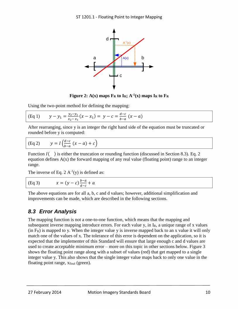
Figure 2: A(x) maps FR to IR; A-1(x) maps IR to FR
Using the two-point method for defining the mapping:
(Eq 1) 𝑦 − 𝑦1 =𝑦2−𝑦1
𝑥2− 𝑥1(𝑥 − 𝑥1) = 𝑦 − 𝑐 =
𝑑−𝑐
𝑏−𝑎 (𝑥 − 𝑎)
After rearranging, since y is an integer the right hand side of the equation must be truncated or
rounded before y is computed:
(Eq 2) 𝑦 = 𝐼 (𝑑−𝑐
𝑏−𝑎 (𝑥 − 𝑎) + 𝑐)
Function 𝐼( ) is either the truncation or rounding function (discussed in Section 8.3). Eq. 2
equation defines A(x) the forward mapping of any real value (floating point) range to an integer
range.
The inverse of Eq. 2 A-1(y) is defined as:
(Eq 3) 𝑥 = (𝑦 − 𝑐)𝑏−𝑎
𝑑−𝑐+ 𝑎
The above equations are for all a, b, c and d values; however, additional simplification and
improvements can be made, which are described in the following sections.
8.3 Error Analysis
The mapping function is not a one-to-one function, which means that the mapping and
subsequent inverse mapping introduce errors. For each value y, in IR, a unique range of x values
(in FR) is mapped to y. When the integer value y is inverse mapped back to an x value it will only
match one of the values of x. The tolerance of this error is dependent on the application, so it is
expected that the implementer of this Standard will ensure that large enough c and d values are
used to create acceptable minimum error – more on this topic in other sections below. Figure 3
shows the floating point range along with a subset of values (red) that get mapped to a single
integer value y. This also shows that the single integer value maps back to only one value in the
floating point range, xfinal (green).
]
]
]]
a b
c
d
A(x)
A-1
(x)
ST 1201.1 - Floating Point to Integer Mapping
27 February 2014 Motion Imagery Standards Board 11
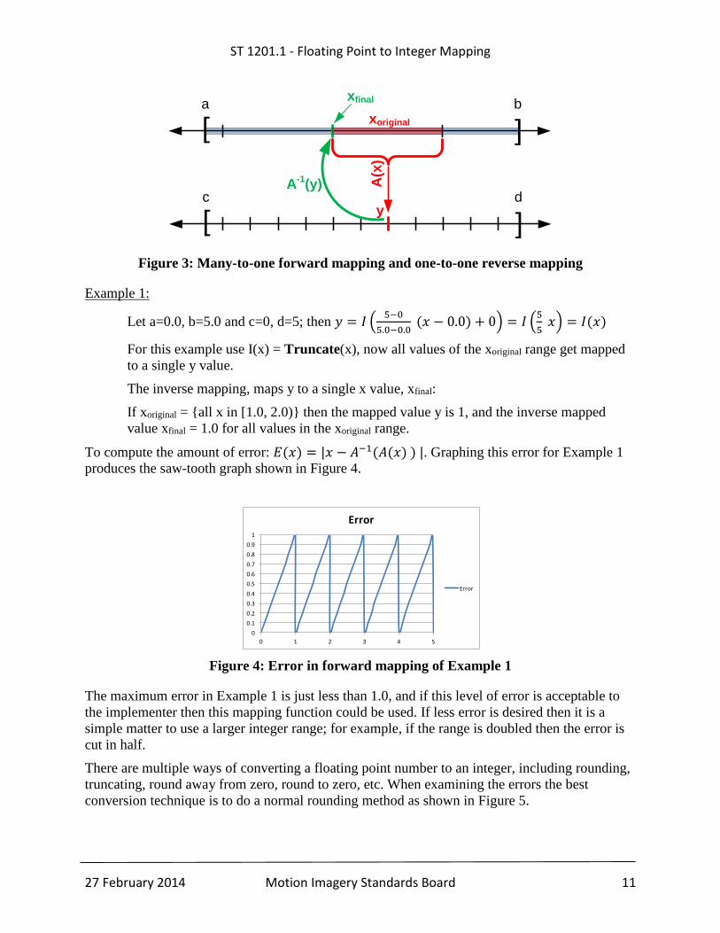
Figure 3: Many-to-one forward mapping and one-to-one reverse mapping
Example 1:
Let a=0.0, b=5.0 and c=0, d=5; then 𝑦 = 𝐼 (5−0
5.0−0.0 (𝑥 − 0.0) + 0) = 𝐼 (
5
5 𝑥) = 𝐼(𝑥)
For this example use I(x) = Truncate(x), now all values of the xoriginal range get mapped
to a single y value.
The inverse mapping, maps y to a single x value, xfinal:
If xoriginal = {all x in [1.0, 2.0)} then the mapped value y is 1, and the inverse mapped
value xfinal = 1.0 for all values in the xoriginal range.
To compute the amount of error: 𝐸(𝑥) = |𝑥 − 𝐴−1(𝐴(𝑥) ) |. Graphing this error for Example 1
produces the saw-tooth graph shown in Figure 4.
Figure 4: Error in forward mapping of Example 1
The maximum error in Example 1 is just less than 1.0, and if this level of error is acceptable to
the implementer then this mapping function could be used. If less error is desired then it is a
simple matter to use a larger integer range; for example, if the range is doubled then the error is
cut in half.
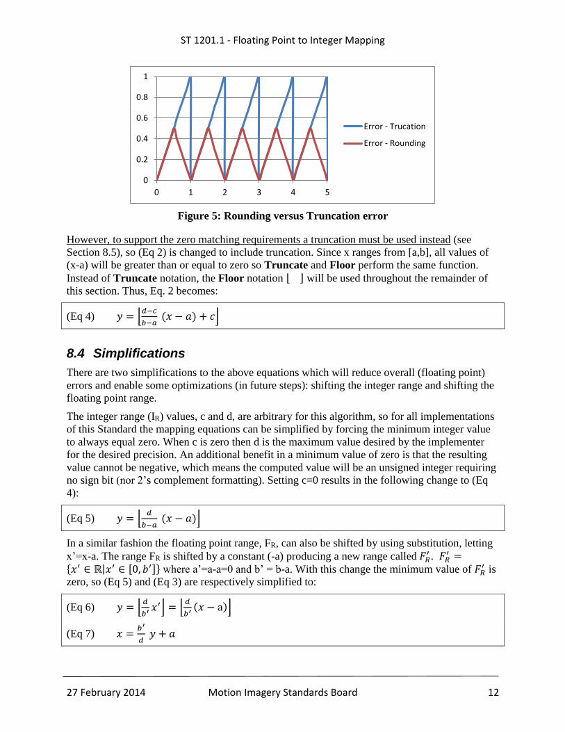
There are multiple ways of converting a floating point number to an integer, including rounding,
truncating, round away from zero, round to zero, etc. When examining the errors the best
conversion technique is to do a normal rounding method as shown in Figure 5.
]
]
a b
]
]
c d
A(x
)
A-1
(y)
y
xoriginal
xfinal
0
0.1
0.2
0.3
0.4
0.5
0.6
0.7
0.8
0.9
1
0 1 2 3 4 5
Error
Error
ST 1201.1 - Floating Point to Integer Mapping
27 February 2014 Motion Imagery Standards Board 12
Figure 5: Rounding versus Truncation error
However, to support the zero matching requirements a truncation must be used instead (see
Section 8.5), so (Eq 2) is changed to include truncation. Since x ranges from [a,b], all values of
(x-a) will be greater than or equal to zero so Truncate and Floor perform the same function.
Instead of Truncate notation, the Floor notation ⌊ ⌋ will be used throughout the remainder of
this section. Thus, Eq. 2 becomes:
(Eq 4) 𝑦 = ⌊𝑑−𝑐
𝑏−𝑎 (𝑥 − 𝑎) + 𝑐⌋
8.4 Simplifications
There are two simplifications to the above equations which will reduce overall (floating point)
errors and enable some optimizations (in future steps): shifting the integer range and shifting the
floating point range.
The integer range (IR) values, c and d, are arbitrary for this algorithm, so for all implementations
of this Standard the mapping equations can be simplified by forcing the minimum integer value
to always equal zero. When c is zero then d is the maximum value desired by the implementer
for the desired precision. An additional benefit in a minimum value of zero is that the resulting
value cannot be negative, which means the computed value will be an unsigned integer requiring
no sign bit (nor 2’s complement formatting). Setting c=0 results in the following change to (Eq
4):
(Eq 5) 𝑦 = ⌊𝑑
𝑏−𝑎 (𝑥 − 𝑎)⌋
In a similar fashion the floating point range, FR, can also be shifted by using substitution, letting
x’=x-a. The range FR is shifted by a constant (-a) producing a new range called 𝐹𝑅′ . 𝐹𝑅
′ ={𝑥′ ∈ ℝ|𝑥′ ∈ [0, 𝑏′]} where a’=a-a=0 and b’ = b-a. With this change the minimum value of 𝐹𝑅
′ is
zero, so (Eq 5) and (Eq 3) are respectively simplified to:
(Eq 6) 𝑦 = ⌊𝑑
𝑏′ 𝑥′⌋ = ⌊𝑑
𝑏′(𝑥 − a)⌋
(Eq 7) 𝑥 =𝑏′
𝑑 𝑦 + 𝑎
0
0.2
0.4
0.6
0.8
1
0 1 2 3 4 5
Error - Trucation
Error - Rounding
ST 1201.1 - Floating Point to Integer Mapping
27 February 2014 Motion Imagery Standards Board 13
8.5 Zero Matching
When the floating point range 𝐹𝑅′ includes zero it is desirable to have that zero value directly map
to an integer in IR; this value is called the Zero Point and is noted as Izero; furthermore, all
negative values in FR should map to integers less than Izero and all positive values should map to
integers that are equal to or greater than Izero.
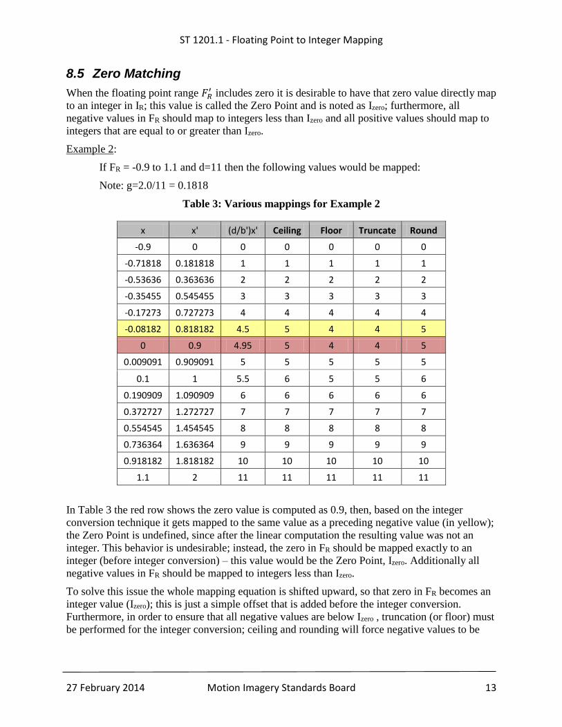
Example 2:
If FR = -0.9 to 1.1 and d=11 then the following values would be mapped:
Note: g=2.0/11 = 0.1818
Table 3: Various mappings for Example 2
x x' (d/b')x' Ceiling Floor Truncate Round
-0.9 0 0 0 0 0 0
-0.71818 0.181818 1 1 1 1 1
-0.53636 0.363636 2 2 2 2 2
-0.35455 0.545455 3 3 3 3 3
-0.17273 0.727273 4 4 4 4 4
-0.08182 0.818182 4.5 5 4 4 5
0 0.9 4.95 5 4 4 5
0.009091 0.909091 5 5 5 5 5
0.1 1 5.5 6 5 5 6
0.190909 1.090909 6 6 6 6 6
0.372727 1.272727 7 7 7 7 7
0.554545 1.454545 8 8 8 8 8
0.736364 1.636364 9 9 9 9 9
0.918182 1.818182 10 10 10 10 10
1.1 2 11 11 11 11 11
In Table 3 the red row shows the zero value is computed as 0.9, then, based on the integer
conversion technique it gets mapped to the same value as a preceding negative value (in yellow);
the Zero Point is undefined, since after the linear computation the resulting value was not an
integer. This behavior is undesirable; instead, the zero in FR should be mapped exactly to an
integer (before integer conversion) – this value would be the Zero Point, Izero. Additionally all
negative values in FR should be mapped to integers less than Izero.
To solve this issue the whole mapping equation is shifted upward, so that zero in FR becomes an
integer value (Izero); this is just a simple offset that is added before the integer conversion.
Furthermore, in order to ensure that all negative values are below Izero , truncation (or floor) must
be performed for the integer conversion; ceiling and rounding will force negative values to be
ST 1201.1 - Floating Point to Integer Mapping
27 February 2014 Motion Imagery Standards Board 14
identical to Izero. Note that this is different than changing the bounds (a,b or c,d) of the equations;
the slope of the linear mapping is not affected by this change.
The adjustment to the mapping equations (Eq 5) and (Eq 6) are:
(Eq 8) Zoffset =𝑑
𝑏′ 𝑎 − ⌊𝑑
𝑏′ 𝑎⌋ , Note: 0.0 ≤ Zoffset < 1.0
(Eq 9) 𝑦 = ⌊𝑑
𝑏′ (x − a) + 𝑍offset⌋
(Eq 10) 𝑥 =𝑏′
𝑑 (𝑦 − 𝑍offset) + a
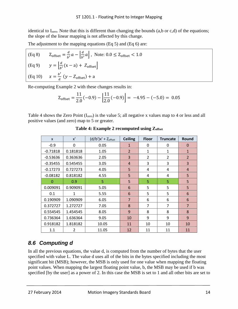
Re-computing Example 2 with these changes results in:
Zoffset =11
2.0(−0.9) − ⌊
11
2.0(−0.9)⌋ = −4.95 − (−5.0) = 0.05
Table 4 shows the Zero Point (Izero) is the value 5; all negative x values map to 4 or less and all
positive values (and zero) map to 5 or greater.
Table 4: Example 2 recomputed using Zoffset
x x' (d/b')x' + Zoffset Ceiling Floor Truncate Round
-0.9 0 0.05 1 0 0 0
-0.71818 0.181818 1.05 2 1 1 1
-0.53636 0.363636 2.05 3 2 2 2
-0.35455 0.545455 3.05 4 3 3 3
-0.17273 0.727273 4.05 5 4 4 4
-0.08182 0.818182 4.55 5 4 4 5
0 0.9 5 5 5 5 5
0.009091 0.909091 5.05 6 5 5 5
0.1 1 5.55 6 5 5 6
0.190909 1.090909 6.05 7 6 6 6
0.372727 1.272727 7.05 8 7 7 7
0.554545 1.454545 8.05 9 8 8 8
0.736364 1.636364 9.05 10 9 9 9
0.918182 1.818182 10.05 11 10 10 10
1.1 2 11.05 12 11 11 11
8.6 Computing d
In all the previous equations, the value d, is computed from the number of bytes that the user
specified with value L. The value d uses all of the bits in the bytes specified including the most
significant bit (MSB); however, the MSB is only used for one value when mapping the floating
point values. When mapping the largest floating point value, b, the MSB may be used if b was
specified [by the user] as a power of 2. In this case the MSB is set to 1 and all other bits are set to
ST 1201.1 - Floating Point to Integer Mapping
27 February 2014 Motion Imagery Standards Board 15
zero. All other uses of the MSB are used to signal special values which are described in Section
7.2.3.
(Eq 11) Nbits = 8 ∗ 𝐿 − 1
(Eq 12) 𝑑 = 2Nbits
(Eq 12) shows that d is a power of two, which will be used for an optimization step described in
Section 8.7.
8.7 Power of 2 Adjustment for b
To improve algorithm efficiency the floating point range, FR, is adjusted to be a power of 2;
however, when this adjustment is made the precision is reduced and the resulting error increases
slightly.
Examining the equation for the mapping shows that the mapping is primarily a simple division,
multiplication and addition: 𝑦 = ⌊𝑑
𝑏′ (𝑥 − 𝑎) + 𝑍offset⌋. Floating point division and
multiplication can easily introduce small numeric floating point rounding errors. To reduce this
error and to provide a more efficient algorithm b' is adjusted to be based on a power of two.
(Eq 13) �̅� = 2⌈𝑙𝑜𝑔2𝑏′⌉
With the adjustments to b' (Eq 9) and (Eq 10) are updated as follows:
(Eq 14) 𝑦 = ⌊𝑑
�̅�(x − a) + 𝑍offset⌋
(Eq 15) 𝑥 =�̅�
𝑑 (𝑦 − 𝑍offset) + a
Since d and �̅� are both powers of two, a small optimization can be made by pre-computing
forward and reverse scaling factors:
(Eq 16) 𝑑
�̅�= 𝑆𝐹 = 2(𝑁𝑏𝑖𝑡𝑠− ⌈𝑙𝑜𝑔2𝑏′⌉)
(Eq 17) �̅�
𝑑= 𝑆𝑅 = 2(⌈𝑙𝑜𝑔2𝑏′⌉−𝑁𝑏𝑖𝑡𝑠)
Now (Eq 14) and (Eq 15) are adjusted and the final mapping equations are complete:
(Eq 18) 𝑦 = ⌊SF(x − a) + 𝑍offset⌋
(Eq 19) 𝑥 = SR (𝑦 − 𝑍offset) + a
8.8 Computing L from known precision
When using these equations there are two starting points that can be defined based either on: (a)
the minimum, maximum and known floating point precision, or (b) the minimum, maximum and
desired length. The preceding sections describe the steps for computing scaling factors based on
(b), knowing the minimum, maximum and number of bytes (L). This section shows the
ST 1201.1 - Floating Point to Integer Mapping
27 February 2014 Motion Imagery Standards Board 16
computation of L based on the known minimum, maximum and known floating point precision
(i.e. starting point (a)).
Given a, b and g; where a is the minimum value of the range, b is the maximum value of the
range and g is the floating point precision to use, then the number of bytes, L, needed to
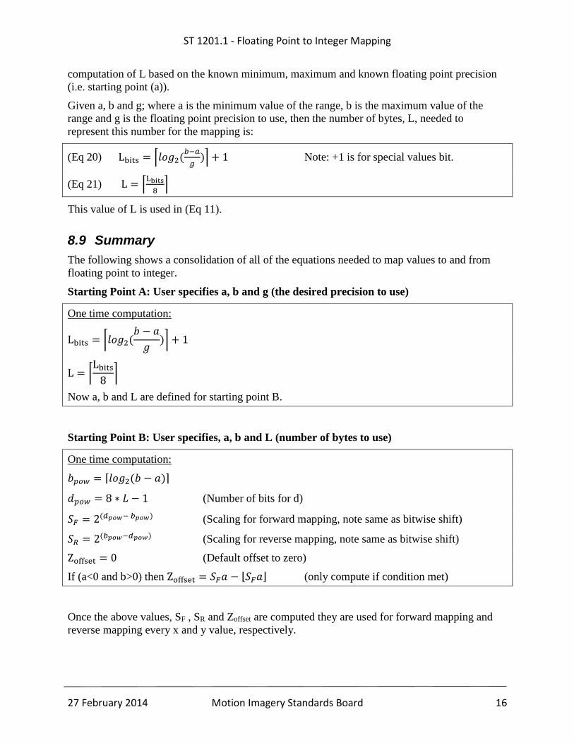
represent this number for the mapping is:
(Eq 20) Lbits = ⌈𝑙𝑜𝑔2(𝑏−𝑎
𝑔)⌉ + 1 Note: +1 is for special values bit.
(Eq 21) L = ⌈Lbits
8⌉
This value of L is used in (Eq 11).
8.9 Summary
The following shows a consolidation of all of the equations needed to map values to and from
floating point to integer.
Starting Point A: User specifies a, b and g (the desired precision to use)
One time computation:
Lbits = ⌈𝑙𝑜𝑔2(𝑏 − 𝑎
𝑔)⌉ + 1
L = ⌈Lbits
8⌉
Now a, b and L are defined for starting point B.
Starting Point B: User specifies, a, b and L (number of bytes to use)
One time computation:
𝑏𝑝𝑜𝑤 = ⌈𝑙𝑜𝑔2(𝑏 − 𝑎)⌉
𝑑𝑝𝑜𝑤 = 8 ∗ 𝐿 − 1 (Number of bits for d)
𝑆𝐹 = 2(𝑑𝑝𝑜𝑤− 𝑏𝑝𝑜𝑤) (Scaling for forward mapping, note same as bitwise shift)
𝑆𝑅 = 2(𝑏𝑝𝑜𝑤−𝑑𝑝𝑜𝑤) (Scaling for reverse mapping, note same as bitwise shift)
Zoffset = 0 (Default offset to zero)
If (a<0 and b>0) then Zoffset = 𝑆𝐹𝑎 − ⌊𝑆𝐹𝑎⌋ (only compute if condition met)
Once the above values, SF , SR and Zoffset are computed they are used for forward mapping and
reverse mapping every x and y value, respectively.

ST 1201.1 - Floating Point to Integer Mapping
27 February 2014 Motion Imagery Standards Board 17
Per x value:
𝑦 = ⌊𝑆𝐹(𝑥 − 𝑎) + 𝑍offset⌋
Per y value:
𝑥 = 𝑆𝑅(𝑦 − 𝑍offset) + 𝑎
See Section 7.2.3 for information on handling special values (i.e. infinity, NaN, etc.) of x and y.
ST 1201.1 - Floating Point to Integer Mapping
27 February 2014 Motion Imagery Standards Board 18
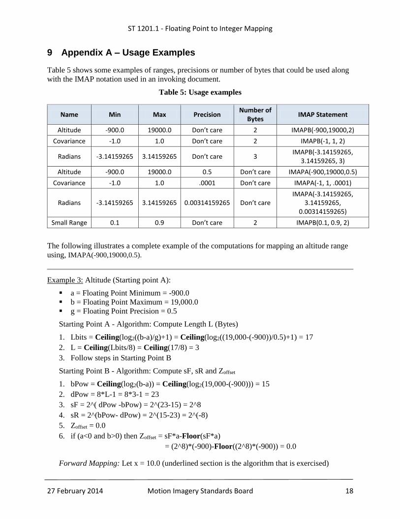
9 Appendix A – Usage Examples
Table 5 shows some examples of ranges, precisions or number of bytes that could be used along
with the IMAP notation used in an invoking document.
Table 5: Usage examples
Name Min Max Precision Number of
Bytes IMAP Statement
Altitude -900.0 19000.0 Don’t care 2 IMAPB(-900,19000,2)
Covariance -1.0 1.0 Don’t care 2 IMAPB(-1, 1, 2)
Radians -3.14159265 3.14159265 Don’t care 3 IMAPB(-3.14159265,
3.14159265, 3)
Altitude -900.0 19000.0 0.5 Don’t care IMAPA(-900,19000,0.5)
Covariance -1.0 1.0 .0001 Don’t care IMAPA(-1, 1, .0001)
Radians -3.14159265 3.14159265 0.00314159265 Don’t care IMAPA(-3.14159265,
3.14159265, 0.00314159265)
Small Range 0.1 0.9 Don’t care 2 IMAPB(0.1, 0.9, 2)
The following illustrates a complete example of the computations for mapping an altitude range
using, IMAPA(-900,19000,0.5).
Example 3: Altitude (Starting point A):
a = Floating Point Minimum = -900.0
b = Floating Point Maximum = 19,000.0
g = Floating Point Precision = 0.5
Starting Point A - Algorithm: Compute Length L (Bytes)
1. Lbits = Ceiling(log2((b-a)/g)+1) = Ceiling(log2((19,000-(-900))/0.5)+1) = 17
2. L = Ceiling(Lbits/8) = Ceiling(17/8) = 3
3. Follow steps in Starting Point B
Starting Point B - Algorithm: Compute sF, sR and Zoffset
1. bPow = Ceiling(log2(b-a)) = Ceiling(log2(19,000-(-900))) = 15
2. dPow = 8*L-1 = 8*3-1 = 23
3. sF = 2^( dPow -bPow) = 2^(23-15) = 2^8
4. sR = 2^(bPow- dPow) = 2^(15-23) = 2^(-8)
5. Zoffset = 0.0
6. if (a<0 and b>0) then Zoffset = sF*a-Floor(sF*a)
= (2^8)*(-900)-Floor((2^8)*(-900)) = 0.0
Forward Mapping: Let x = 10.0 (underlined section is the algorithm that is exercised)
ST 1201.1 - Floating Point to Integer Mapping
27 February 2014 Motion Imagery Standards Board 19
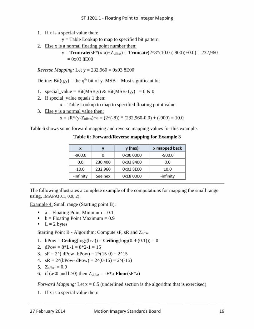
1. If x is a special value then:
y = Table Lookup to map to specified bit pattern
2. Else x is a normal floating point number then:
y = Truncate(sF*(x-a)+Zoffset) = Truncate(2^8*(10.0-(-900))+0.0) = 232,960
= 0x03 8E00
Reverse Mapping: Let y = 232,960 = 0x03 8E00
Define: Bit(q,y) = the qth bit of y. MSB = Most significant bit
1. special_value = Bit(MSB,y) & Bit(MSB-1,y) = 0 & 0
2. If special_value equals 1 then:
x = Table Lookup to map to specified floating point value
3. Else y is a normal value then:
x = sR*(y-Zoffset)+a = (2^(-8)) * (232,960-0.0) + (-900) = 10.0
Table 6 shows some forward mapping and reverse mapping values for this example.
Table 6: Forward/Reverse mapping for Example 3
x y y (hex) x mapped back
-900.0 0 0x00 0000 -900.0
0.0 230,400 0x03 8400 0.0
10.0 232,960 0x03 8E00 10.0
-infinity See hex 0xE8 0000 -infinity
The following illustrates a complete example of the computations for mapping the small range
using, IMAPA(0.1, 0.9, 2).
Example 4: Small range (Starting point B):
a = Floating Point Minimum = 0.1
b = Floating Point Maximum = 0.9
L = 2 bytes
Starting Point B - Algorithm: Compute sF, sR and Zoffset
1. bPow = Ceiling(log2(b-a)) = Ceiling(log2(0.9-(0.1))) = 0
2. dPow = 8*L-1 = 8*2-1 = 15
3. sF = 2^( dPow -bPow) = 2^(15-0) = 2^15
4. sR = 2^(bPow- dPow) = 2^(0-15) = 2^(-15)
5. Zoffset = 0.0
6. if (a<0 and b>0) then Zoffset = sF*a-Floor(sF*a)
Forward Mapping: Let x = 0.5 (underlined section is the algorithm that is exercised)
1. If x is a special value then:
ST 1201.1 - Floating Point to Integer Mapping
27 February 2014 Motion Imagery Standards Board 20
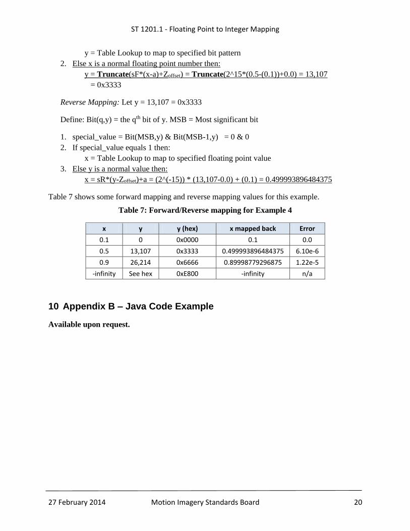
y = Table Lookup to map to specified bit pattern
2. Else x is a normal floating point number then:
y = Truncate(sF*(x-a)+Zoffset) = Truncate(2^15*(0.5-(0.1))+0.0) = 13,107
= 0x3333
Reverse Mapping: Let y = 13,107 = 0x3333
Define: Bit(q,y) = the qth bit of y. MSB = Most significant bit
1. special_value = Bit(MSB,y) & Bit(MSB-1,y) = 0 & 0
2. If special_value equals 1 then:
x = Table Lookup to map to specified floating point value
3. Else y is a normal value then:
x = sR*(y-Zoffset)+a = (2^(-15)) * (13,107-0.0) + (0.1) = 0.499993896484375
Table 7 shows some forward mapping and reverse mapping values for this example.
Table 7: Forward/Reverse mapping for Example 4
x y y (hex) x mapped back Error
0.1 0 0x0000 0.1 0.0
0.5 13,107 0x3333 0.499993896484375 6.10e-6
0.9 26,214 0x6666 0.89998779296875 1.22e-5
-infinity See hex 0xE800 -infinity n/a
10 Appendix B – Java Code Example
Available upon request.