Embed Size (px)
Citation preview
FLORIDA STATE COLLEGE AT JACKSONVILLE INFORMATION TRANSPORT SYSTEM SPECIFICATIONS
FSCJ_ITS_Specs_v1.1.docx 1
IINFORMATION NFORMATION TTRANSPORT RANSPORT SSYSTEM YSTEM SSPECIFICATIONSPECIFICATIONS
Ver. May 12, 2011
Contact Information
Primary: John Slevin Enterprise Systems Group
Lead Network Infrastructure & VOIP SE Information Transport Systems
[email protected] 904-997-2993
Secondary: John D. (J.D.) Hudnall
Enterprise Systems Group Network Infrastructure Engineer
Information Transport Systems Specialist [email protected]
904-997-2943
Tertiary: Ron Smith Enterprise Systems Group
AVP of Computing Infrastructure, Security, Compliance & CSO
[email protected] 904-997-2997
INFORMATIONNFORMATION T TECHNOLOGYECHNOLOGYFLORIDA STATE COLLEGE AT JACKSONVILLE

FLORIDA STATE COLLEGE AT JACKSONVILLE INFORMATION TRANSPORT SYSTEM SPECIFICATIONS
FSCJ_ITS_Specs_v1.1.docx 2
(Blank Page)
FLORIDA STATE COLLEGE AT JACKSONVILLE INFORMATION TRANSPORT SYSTEM SPECIFICATIONS
FSCJ_ITS_Specs_v1.1.docx 3
1. Introduction ............................................................................................................................................. 4 1.1. Purpose ............................................................................................................................................. 4 1.2. Applicable Standards ...................................................................................................................... 5
TIA/EIA ................................................................................................................................................... 5 NFPA ........................................................................................................................................................ 5 ISO/IEC .................................................................................................................................................... 5
1.3. Additional Support .......................................................................................................................... 5 1.3.1. PanGen ™ System Warranty ...................................................................................................... 5 1.3.2. Contractor Agreement ................................................................................................................ 5
2. Telecommunication Network System Requirements .............................................................................. 6 2.1. Description ....................................................................................................................................... 6 2.2. Supported Applications ................................................................................................................... 6 2.3. Additional Requirements ................................................................................................................ 7
3. Work Area Subsystem .............................................................................................................................. 8 3.1. Patch Cords and Modular Connectors .......................................................................................... 8
3.1.1. Copper ........................................................................................................................................ 8 3.1.1.1. Category 6 UTP ................................................................................................................... 8
3.1.1.2. Additional Copper Cabling Connectors .................................................................................. 9 3.1.2. Fiber Optic .................................................................................................................................. 9
3.2. Outlets and Surface Mount Boxes ................................................................................................ 10 Faceplates ............................................................................................................................................... 10 Modular Furniture Faceplates ................................................................................................................ 11 Faceplate Frames and Inserts ................................................................................................................. 11 Stainless Steel Faceplates ....................................................................................................................... 11 Surface Mount Boxes ............................................................................................................................. 11 Other Outlet Components ....................................................................................................................... 12
3.3. Surface Raceway and Vertical Outlet Pole ................................................................................. 13 3.3.1. Multi-Channel (Coming Soon) ................................................................................................. 13 3.3.2. Single Channel (Coming Soon) ................................................................................................ 13 3.3.3. Outlet Pole ................................................................................................................................ 13
4. Horizontal Cabling Subsystem .............................................................................................................. 14 4.1. Copper UTP Cable ........................................................................................................................ 15
Category 6 UTP Cable ........................................................................................................................... 15 4.2. Fiber Cable ..................................................................................................................................... 18
Horizontal Distances - Optical Fiber Links ............................................................................................ 18 Specifications ......................................................................................................................................... 18 Performance ........................................................................................................................................... 18
5. Telecommunications Room ................................................................................................................... 20 5.1. Cable Termination Hardware ...................................................................................................... 20
5.1.1. Category 6 Unshielded Twisted Pair UTP ............................................................................... 20 5.1.1.1. Modular Patch Panels and Cords ....................................................................................... 20
Fiber Termination Hardware .................................................................................................................. 21 5.1.1.2. Fiber Optic Connectors and Patch Cords .......................................................................... 21
5.2. Fiber Optic Equipment ................................................................................................................. 22 Enclosures .............................................................................................................................................. 22
5.3. Cable Management ........................................................................................................................ 22
FLORIDA STATE COLLEGE AT JACKSONVILLE INFORMATION TRANSPORT SYSTEM SPECIFICATIONS
FSCJ_ITS_Specs_v1.1.docx 4
5.3.1. Vertical Cable Management ..................................................................................................... 22 5.3.2. Rack Cable Management ...................................................................................................... 23 5.3.2.1. TAK-TY ® Hook & Loop Cable Tie ................................................................................... 23
5.3.4. Wall or Backboard Mounted Cable Management .................................................................... 23 5.3.4.1. D – Rings (Metallic) (To be expanded on in Q2 2010) ..................................................... 23
5.3.5. Ladder Rack Accessories ......................................................................................................... 23 5.3.5.1. Waterfall Accessories ........................................................................................................ 23 5.3.5.2. Threaded Rod Cover .......................................................................................................... 24 5.3.5.3. Stackable Cable Rack Spacers ........................................................................................... 24
5.3.6. Cable Support System Accessories .......................................................................................... 24 5.3.7. Cable Support System .............................................................................................................. 25 5.3.8. Fiber Routing Systems ............................................................................................................. 26
5.3.9. Rack Equipment ......................................................................................................................... 26 6. Backbone Cabling System ..................................................................................................................... 28
6.1 Voice Backbone ............................................................................................................................... 28 Voice Cable ............................................................................................................................................ 28
6.1.1.1. Multi-pair Category 5e UTP Cable ................................................................................... 28 Voice Termination and Cross-connects ................................................................................................. 28
6.1.1.2. Modular Patch Panels and Cords ....................................................................................... 29 6.2. Data Backbone ............................................................................................................................... 29
Data Cable .............................................................................................................................................. 29 Data Termination and Cross Connects ................................................................................................... 29
6.2.1. Fiber Connectors and Patch Cords ....................................................................................... 29 7. Identification .......................................................................................................................................... 31
7.1. Patch Panels and Communications Outlets ................................................................................ 31 8. Testing Data ........................................................................................................................................... 32
Approved Test Leads For PANDUIT Mini-Com® TX6™ ....................................................................... 32 Permanent Link ...................................................................................................................................... 32 Channel ................................................................................................................................................... 33
Accepted Test Leads For PANDUIT Mini-Com® TX6™ ........................................................................ 34 Permanent Link ...................................................................................................................................... 34
9. Appendixes: ............................................................................................................................................ 35 9.1. Appendix 7 ..................................................................................................................................... 35
1. Introduction
1.1. Purpose The purpose of this document is to provide documentation to cabling professionals interested in providing Florida State College at Jacksonville commercial building structured cabling.
The documentation includes:
• Product specifications • Minimum product performance • Structured cabling design considerations • Installation guidelines

FLORIDA STATE COLLEGE AT JACKSONVILLE INFORMATION TRANSPORT SYSTEM SPECIFICATIONS
FSCJ_ITS_Specs_v1.1.docx 5
The information contained in this document is based on our experience to date and is believed to be reliable. It is intended as a guide for use by persons having technical skill and is to be used with their own discretion and risk. Dimensions contained herein are for reference purposes only. For specific dimensional requirements consult the factory.
1.2. Applicable Standards The following industry standards are the basis for the structured cabling system described in this document. The list is incorporated by this reference to them.
TIA/EIA • TIA/EIA-568-B Commercial Building Telecommunications Cabling Standard • TIA/EIA-568-B.1 General Requirements • TIA/EIA-568-B.2 Balanced Twisted Pair Cabling Components Standard • TIA/EIA-568-B.2-1 Transmission performance for 4 pair 100 Ώ category 6 • TIA/EIA-568-B.3 Optical Fiber Cabling Components Standard • TIA/EIA-569-A Commercial Building Standard for Telecom
Pathways and Spaces • TIA/EIA-606 Administration Standard for the Telecommunications
Infrastructure of Commercial Buildings • TIA/EIA-607 Commercial Building Grounding/Bonding Requirements
NFPA • NFPA-70 National Electric Code (NEC)-2002
ISO/IEC • ISO/IEC 11801 Generic Cabling for Customer Premises The most recent versions of all documents apply to this project. If there is a conflict between applicable documents, the order above shall dictate the order of precedence in resolving the issue unless an enforceable local or national code is in effect.
1.3. Additional Support
1.3.1. PanGen ™ System Warranty A PanGen ™ System Warranty shall provide a complete system warranty to guarantee end-to-end high performance cabling systems that meet application requirements. The guarantee shall include cable and connectivity components and have one point of contact for all cabling system issues. The system shall be warranted for a period of at least 25 years.
1.3.2. Contractor Agreement In order for the structured cabling system or additional links to be eligible for warranty coverage, an installation company trained and certified by BICSI, PANDUIT ® and General Cable must install them. The contractor shall have completed standards based product and installation training. A copy of the BICSI Certificate, PCI Certificate or PanGen Installer Certificate shall be submitted in the proposal.
FLORIDA STATE COLLEGE AT JACKSONVILLE INFORMATION TRANSPORT SYSTEM SPECIFICATIONS
FSCJ_ITS_Specs_v1.1.docx 6
2. Telecommunication Network System Requirements
2.1. Description The Structured Cabling System shall consist of any one or all of the following structured cabling elements or subsystems:
• Work area • Horizontal cabling • Telecommunications room (or horizontal cross connect) • Backbone cabling • Equipment room • Entrance facility • All cable support structure
2.2. Supported Applications The Structured Cabling System shall be capable of supporting and/or integrating the following:
• Analogue and digital voice applications • Data applications • Local area network services • Wide area network services • Video services • Low voltage devices for building controls
The applications that shall be supported include, but are not limited to: • Data Communications
• Token Ring (IEEE 802.5) • Ethernet (10 Base-T, 100 Base-T, 1000 Base-T) • 100 Base VG Any LAN • ATM (155 Mbps, 622 Mbps) • Fiber Distributed Data Interface (FDDI) • Twisted Pair-Physical Medium Dependant (TP-PMD) • IBM System 3X • IBM AS/400 • AppleTalk • Arcnet • ISDN • CDDI • Any other application designed to run on a generic structured cabling
system designed and installed to TIA or ISO structured cabling standards • Data Processing
• Mainframe access client server, enterprise server, messaging systems and electronic mail, client database, etc
• Voice Applications • Digital and analog PBXs and key systems
• Video • Analogue video, digital video, and video conferencing
• Building Services
FLORIDA STATE COLLEGE AT JACKSONVILLE INFORMATION TRANSPORT SYSTEM SPECIFICATIONS
FSCJ_ITS_Specs_v1.1.docx 7
• Heating, ventilation, and air conditioning (HVAC) monitoring and control
• Lighting monitoring and control • Motion sensors • Public address and paging systems • Security • Access Control Systems • Other low voltage devices
• Multiple Services • The structured cabling system shall also support backward and
forward migration of applications with minimal disruption to existing services or personnel, allowing for quick moves, adds, and changes
2.3. Additional Requirements • Categorized copper product shall be used in conjunction with General Cable of
equivalent or higher Category cable as verified by ETL, UL or PANDUIT ®
engineering • All structured cabling products shall be installed according to any applicable
instructions • All networks and other applications shall be installed per applicable standards and
manufacturers’ guidelines and transmitted over the appropriate minimum Category copper cable or fiber cable for which it was intended to operate on
• All applicable local, state, national, and federal electrical and fire safety standards shall be adhered to during and after installation
FLORIDA STATE COLLEGE AT JACKSONVILLE INFORMATION TRANSPORT SYSTEM SPECIFICATIONS
FSCJ_ITS_Specs_v1.1.docx 8
3. Work Area Subsystem The Work Area shall consist of the connectivity equipment used to connect the horizontal cabling subsystem and the equipment in the work area. Both copper and fiber media shall be supported. The connectivity equipment shall include the following options:
• Patch (equipment) cords and modular connectors • Outlets and surface mount boxes • Surface raceway and outlet poles
3.1. Patch Cords and Modular Connectors The modular connectors and patch cords will be chosen to match the horizontal cabling medium and rating. The same manufacturer shall provide the modular connectors and patch cords. The total patch cord length at the work area is not to exceed three meters (10 ft). Exception: When implementing an open office cabling system as specified under TIA/EIA 568-B (see section 3.4).
3.1.1. Copper The PANDUIT ® MINI-COM ® Network Cabling System or AVP of Computing Infrastructure approved equivalent shall be used for the Work Area subsystem, including all modular connectors. The network cabling system shall be comprised of modular connectors in support of high-speed networks and applications designed for implementation on copper cabling. All outlets shall utilize fully interchangeable and individual connector modules that mount side-by-side to facilitate quick and easy moves, adds and changes.
3.1.1.1. Category 6 UTP MINI-COM ® TX6 TM Plus Jack Modules shall be Category 6 modules featuring eight positions that shall be used in all work areas and shall exceed the connector requirements of the TIA/EIA Category 6 standard. Jack module shall use forward motion termination to optimize performance by maintaining cable pair geometry and eliminating conductor untwist. The termination cap shall provide strain relief on the cable jacket, ensure cable twists are maintained to within 1/8” (3.18mm) and include a wiring scheme label. The wiring scheme label shall be available with both T568A and T568B wiring schemes. All terminations shall use the T568B (B) wiring scheme. The modules shall terminate four pair 22 - 26 AWG 100 ohm solid unshielded twisted pair cable. The modules shall be universal in design, including complying with the intermatability standard IEC 60603-7 for backward compatibility. Category 6 modules shall have UL and CSA approval. The modules shall have ETL verified Category 6 performance and ISO Class E performance (as defined in ISO/IEC 11801) in both the basic and channel links. They shall be universal in design, accepting six or eight pair modular plugs without damage to the outer module contacts. The modules shall be able to be re-terminated a minimum of 10 times and be available in 11 standard colors for color-coding purposes with the preferred color being blue (CJ688TGBU). The module shall snap into all MINI-COM ® outlets and patch panels. The module shall include an ivory colored base to signify Category 6 330 MHz performance.
Part Number Style Category Colors CJ688TG** RJ45 6 11
** Designates color
FLORIDA STATE COLLEGE AT JACKSONVILLE INFORMATION TRANSPORT SYSTEM SPECIFICATIONS
FSCJ_ITS_Specs_v1.1.docx 9
PanGen TM Category 6 Patch Cords shall be factory terminated with modular plugs featuring a tangle-free latch design and clear strain-relief boots to support easy moves, adds and changes. Each patch cord shall be 100% performance tested at the factory to the TIA/EIA Category 6 standard. The patch cords shall come in standard lengths of three, five, seven, 10, and 14 feet and six standard colors of Blue, Green, and Red. Red (**=RD) shall be used for Enterprise equipment, Blue (**=BU) shall be used for Staff Connections, and Green (**=GR) shall be used for Student Connections.
Part Number Length (ft) Length (M) UTPSP3**Y 3 0.91 UTPSP5**Y 5 1.52 UTPSP7**Y 7 2.13 UTPSP10**Y 10 3.04 UTPSP14**Y 14 4.27
** Designates color
3.1.1.2. Additional Copper Cabling Connectors Additional MINI-COM ® Modules for copper shall include the following: • 50 and 75 Ohm BNC coax coupler modules, male-male • F-Type coax coupler module, male-male threaded • RCA connector modules with black, red, yellow, and white inserts
Solder pass through and punchdown termination types • S-Video connectors modules - coupler and punchdown termination
types • Blank module to reserve space for future additions
The connectors shall snap into all MINI-COM ® outlets and patch panels.
Part Number Style Medium Termination Style Colors CMBA** BNC Coax Coupler 5 CMBA75** BNC Coax Coupler 5 CMFBA** F-Type Copper Coupler 5 CMFSR** F-Type Copper Coupler 5 CJRR** RCA - red Copper Punchdown 5 CJRY** RCA - yellow Copper Punchdown 5 CJRW** RCA - white Copper Punchdown 5 CMRPR** RCA - red Copper Pass through 5 CMRPY** RCA - yellow Copper Pass through 5 CMRPW** RCA - white Copper Pass through 5 CMSVC** S-Video Copper Pass through 5 CJSV** S-Video Copper Punchdown 5 CMB** Blank - - 5
** Designates color
3.1.2. Fiber Optic The PANDUIT ®
MINI-COM ® network cabling system or AVP of Computing
Infrastructure approved equivalent shall be comprised of PANDUIT ® Fiber Optic modular connectors in support of high-speed networks and applications designed for implementation on multimode (50/125µm) glass fiber cabling.
All outlets shall utilize interchangeable and individual connector modules that mount side by side to facilitate quick and easy moves, adds, and changes. Approved components of

FLORIDA STATE COLLEGE AT JACKSONVILLE INFORMATION TRANSPORT SYSTEM SPECIFICATIONS
FSCJ_ITS_Specs_v1.1.docx 10
the Fiber Termination Hardware for the Work Area Subsystem shall include but are not limited to: LC small form factor (SFF) fiber optic adapters with integrated panel retention clips are TIA/EIA-604 FOCIS-10 compatible. Each LC simplex adapter shall connect one LC connector pair in one module space. Each LC duplex adapter shall connect two LC connector pairs in one module space. LC adapters and adapter modules shall include phosphor bronze split sleeves for multimode applications or zirconia ceramic split sleeves for singlemode applications. Standards requirements: TIA/EIA-604 FOCIS-10 compatible; exceeds TIA/EIA-568-B.3 requirements Split sleeve material: Phosphor bronze or zirconia ceramic (required for singlemode applications) Insertion loss: .1dB average (multimode and singlemode); supports the performance of FOCIS-10 compliant connectors/patch cords Return loss: Supports singlemode (>40dB for SPC and >55dB for UPC) and multimode (>20dB) connector polish performance
Part Number Description FADSLCEI-L LC Sr/Sr. Dupl Fiber Optic Adapter El (Phos)
3.2. Outlets and Surface Mount Boxes The outlets and surface mount boxes shall support the network system by providing high-density in-wall, surface mount or modular office furniture cabling applications. The outlets consist of faceplates for flush and recessed in-wall mounting as well as mounting to the modular office furniture systems. The surface mount boxes can be mounted where in-wall applications are not possible or to support applications where surface mount is the best option.
All outlets shall utilize fully the interchangeable and individual MINI-COM ® connector modules that mount side by side to facilitate quick and easy moves, adds and changes. All outlets shall be manufactured from high-impact thermoplastic material with a U.L. flammability rating of 94 HB or better. All outlets and surface mount boxes shall be available in four colors including Off White (IW), Electrical Ivory (EI), White (WH) and International Gray (IG).
Faceplates MINI-COM ® Executive Series Faceplates shall be one, two, four and six port vertical single gang and 10 port vertical double gang faceplates with combination head screws, screw covers, labels, label covers and a curved, designer appearance. The faceplates shall mount to standard U.S. NEMA boxes and adapters with screw-to-screw dimensions of 3.28" (83.3mm). The insert labels shall meet UL 969. Each faceplate shall accept MINI-COM ® modules that can be individually inserted and removed as required.
Part Number Gang Number of Modules CFPE1** Single 1 CFPE2** Single 2 CFPE4** Single 4 CFPE6** Single 6 CFPE10**-2G Double 10
FLORIDA STATE COLLEGE AT JACKSONVILLE INFORMATION TRANSPORT SYSTEM SPECIFICATIONS
FSCJ_ITS_Specs_v1.1.docx 11
** Designates color
Modular Furniture Faceplates MINI-COM ® Modular Furniture Faceplates shall be four-port flat or angled and two port angled faceplates that snap directly into TIA/EIA standard furniture openings. The two port, angled faceplate shall provide a 45° slope to the side, in-line with the cable running through the furniture channel. If required, an extender shall be used with the four port flat faceplate to provide 12.7mm (0.5”) additional depth. Each faceplate shall accept MINI-COM ® modules that can be individually inserted and removed as required.
Part Number Number of Modules Orientation CFFP4** 4 Flat CFFPA2** 2 Sloped CFFPL4** 4 Flat with Label CFFPLA4** 4 Sloped with Label
** Designates color
Faceplate Frames and Inserts MINI-COM ® Executive Series Faceplate Frames shall be vertical, single and double gang frames with combination head screws, screw covers, labels, and a curved designer appearance. The faceplates shall mount onto standard U.S. NEMA boxes and adapters with screw-to-screw dimensions of 3.28" (83.3mm). Each faceplate frame shall accept flat, sloped, sloped shuttered, sloped recessed and blank 1/2 and 1/3 size module inserts that can be individually inserted and removed as required from the front of the frame without removing the frame.
Part Number Gang Number of Modules CBE** Single Up to 6 CBE**-2G Double Up to 12
** Designates color
Stainless Steel Faceplates MINI-COM ® Stainless Steel Faceplates shall be two, four and six-port vertical single gang and four, eight and 10 port double gang faceplates with combination head stainless steel screws. The faceplates shall mount to standard U.S. NEMA boxes and adapters with screw-to-screw dimensions of 3.28" (83.3mm). Faceplates shall be flush mounted for clean look. Stainless steel material shall be riveted to high impact ABS backing to provide a durable faceplate with brush finish. Each faceplate shall accept individual copper and fiber optic connector modules that can be individually inserted and removed as required.
Part Number Gang Finish Number of Modules CFP2S Single Stainless steel 2 CFP4S Single Stainless steel 4 CFP6S Single Stainless steel 6 CFP4S-2G Double Stainless steel 4 CFP8S-2G Double Stainless steel 8 CFP10S-2G Double Stainless steel 10
Surface Mount Boxes MINI-COM ® Low Profile Surface Mount Boxes shall be one, two, four, six and 12-port low profile surface mount boxes with a 28mm (1.1”) maximum height. All connections (with exception of the 12 port low profile box) shall exit one side of the box, parallel to
FLORIDA STATE COLLEGE AT JACKSONVILLE INFORMATION TRANSPORT SYSTEM SPECIFICATIONS
FSCJ_ITS_Specs_v1.1.docx 12
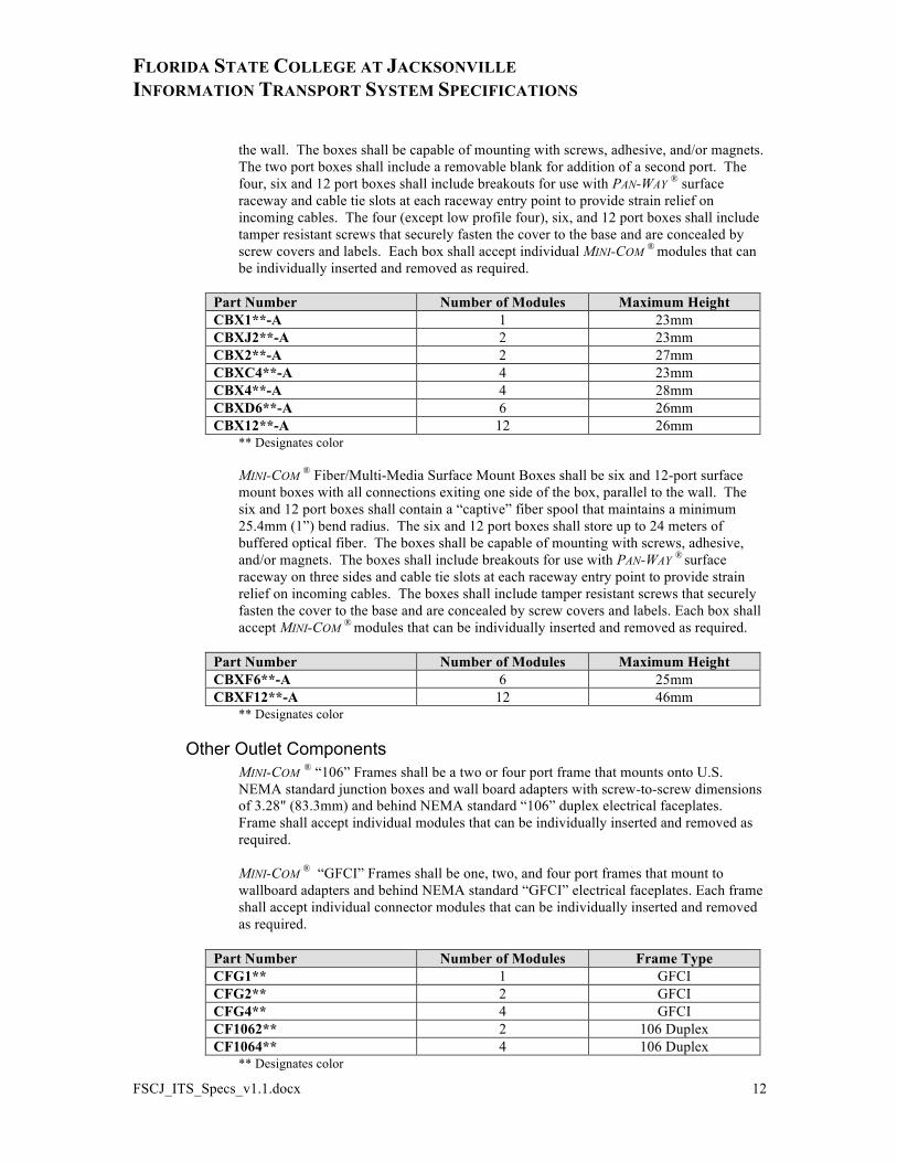
the wall. The boxes shall be capable of mounting with screws, adhesive, and/or magnets. The two port boxes shall include a removable blank for addition of a second port. The four, six and 12 port boxes shall include breakouts for use with PAN-WAY ® surface raceway and cable tie slots at each raceway entry point to provide strain relief on incoming cables. The four (except low profile four), six, and 12 port boxes shall include tamper resistant screws that securely fasten the cover to the base and are concealed by screw covers and labels. Each box shall accept individual MINI-COM ® modules that can be individually inserted and removed as required.
Part Number Number of Modules Maximum Height CBX1**-A 1 23mm CBXJ2**-A 2 23mm CBX2**-A 2 27mm CBXC4**-A 4 23mm CBX4**-A 4 28mm CBXD6**-A 6 26mm CBX12**-A 12 26mm
** Designates color MINI-COM ® Fiber/Multi-Media Surface Mount Boxes shall be six and 12-port surface mount boxes with all connections exiting one side of the box, parallel to the wall. The six and 12 port boxes shall contain a “captive” fiber spool that maintains a minimum 25.4mm (1”) bend radius. The six and 12 port boxes shall store up to 24 meters of buffered optical fiber. The boxes shall be capable of mounting with screws, adhesive, and/or magnets. The boxes shall include breakouts for use with PAN-WAY ® surface raceway on three sides and cable tie slots at each raceway entry point to provide strain relief on incoming cables. The boxes shall include tamper resistant screws that securely fasten the cover to the base and are concealed by screw covers and labels. Each box shall accept MINI-COM ® modules that can be individually inserted and removed as required.
Part Number Number of Modules Maximum Height CBXF6**-A 6 25mm CBXF12**-A 12 46mm
** Designates color
Other Outlet Components MINI-COM ® “106” Frames shall be a two or four port frame that mounts onto U.S. NEMA standard junction boxes and wall board adapters with screw-to-screw dimensions of 3.28" (83.3mm) and behind NEMA standard “106” duplex electrical faceplates. Frame shall accept individual modules that can be individually inserted and removed as required. MINI-COM ® “GFCI” Frames shall be one, two, and four port frames that mount to wallboard adapters and behind NEMA standard “GFCI” electrical faceplates. Each frame shall accept individual connector modules that can be individually inserted and removed as required.
Part Number Number of Modules Frame Type CFG1** 1 GFCI CFG2** 2 GFCI CFG4** 4 GFCI CF1062** 2 106 Duplex CF1064** 4 106 Duplex
** Designates color
FLORIDA STATE COLLEGE AT JACKSONVILLE INFORMATION TRANSPORT SYSTEM SPECIFICATIONS
FSCJ_ITS_Specs_v1.1.docx 13
3.3. Surface Raceway and Vertical Outlet Pole Surface raceway and vertical outlet poles refers to a surface raceway system used for branch circuit wiring and/or data network, voice, video and other low-voltage cabling. Surface raceway shall be used in solid wall applications or for applications where moves, adds and changes are very typical to the workflow. The raceway system shall consist of raceway, appropriate fittings and accessories to complete installation per electrical and/or data drawings.
Non-metallic surface raceway is to be utilized in dry interior locations only as covered in Article 388of the NEC, as adopted by the NFPA and as approved by the ANSI.
3.3.1. Multi-Channel (Coming Soon)
3.3.2. Single Channel (Coming Soon)
3.3.3. Outlet Pole Outlet Poles refers to dual channel, floor-to-ceiling pole that provides convenient access to power and communication outlets. The Outlet Pole provides a floor space efficient and MAC friendly solution to power and communication access in open office, education, retail, factory, or warehouse applications. The outlet poles shall be available in 11’ or 13’ lengths. Power and Communication Channels The Power and Communications Pole channel shall be aluminum, in either off-white or electrical ivory color, with a cross sectional area of 2.90" X 1.77" with two separate compartments. One compartment is to be factory wired with two, (2) duplex style 20A, 125V NEMA 5-20R grounding-type specification grade receptacles, and colored, to match the pole finish. Receptacles must be UL tested to meet the performance requirements of Fed. Spec. W-C695G General Specification for Electrical Power Connectors and conform to NEMA specification WD 1-7.01 to 7.10 “Heavy Duty General Use Grounding Receptacle”. Receptacles shall also be UL Listed and be in compliance with UL-498. The harness is to be single circuit (2 conductor plus ground) with #12 AWG solid type THHN conductors, factory assembled to the receptacles. Six-inch (6”) conductor leads are to be furnished for termination to the overhead wiring system. A power entry box with ½, and ¾ " conduit breakouts, and 8” removable plate must be provided at the top of the power compartment to facilitate the hard wiring of the pole harness. The second compartment is to be for field installation of telephone or data network cabling. A nonmetallic cover, which is removable and easily cut to create an opening for installation of communications faceplates, shall be provided to enclose the channel. The channel shall accept Snap-On communication faceplates or a standard faceplate bracket capable of mounting a NEMA standard single-gang communications faceplate. The channel shall be capable of mounting up to six communication faceplates, providing up to 24 communication ports. Communication Only Channel The Communications Only Pole shall be aluminum, in either off-white or electrical ivory color, with a cross sectional area of 2.90" x 1.77" with one compartment.
FLORIDA STATE COLLEGE AT JACKSONVILLE INFORMATION TRANSPORT SYSTEM SPECIFICATIONS
FSCJ_ITS_Specs_v1.1.docx 14
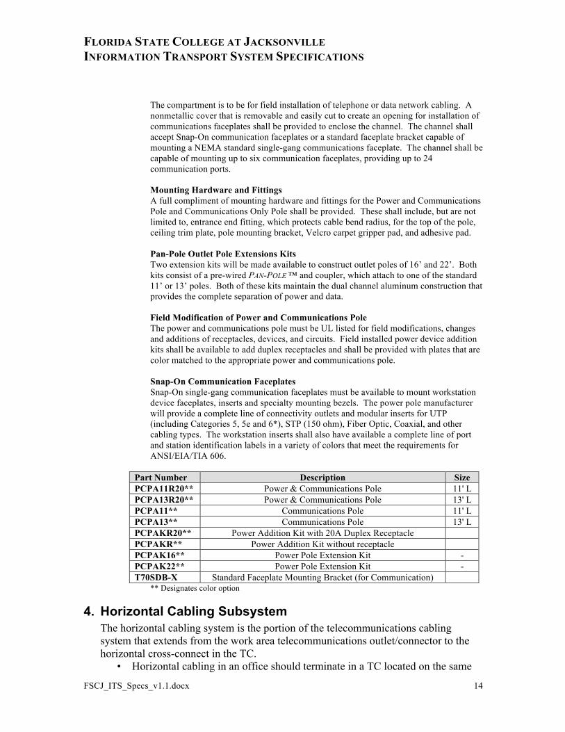
The compartment is to be for field installation of telephone or data network cabling. A nonmetallic cover that is removable and easily cut to create an opening for installation of communications faceplates shall be provided to enclose the channel. The channel shall accept Snap-On communication faceplates or a standard faceplate bracket capable of mounting a NEMA standard single-gang communications faceplate. The channel shall be capable of mounting up to six communication faceplates, providing up to 24 communication ports. Mounting Hardware and Fittings A full compliment of mounting hardware and fittings for the Power and Communications Pole and Communications Only Pole shall be provided. These shall include, but are not limited to, entrance end fitting, which protects cable bend radius, for the top of the pole, ceiling trim plate, pole mounting bracket, Velcro carpet gripper pad, and adhesive pad. Pan-Pole Outlet Pole Extensions Kits Two extension kits will be made available to construct outlet poles of 16’ and 22’. Both kits consist of a pre-wired PAN-POLE ™ and coupler, which attach to one of the standard 11’ or 13’ poles. Both of these kits maintain the dual channel aluminum construction that provides the complete separation of power and data. Field Modification of Power and Communications Pole The power and communications pole must be UL listed for field modifications, changes and additions of receptacles, devices, and circuits. Field installed power device addition kits shall be available to add duplex receptacles and shall be provided with plates that are color matched to the appropriate power and communications pole. Snap-On Communication Faceplates Snap-On single-gang communication faceplates must be available to mount workstation device faceplates, inserts and specialty mounting bezels. The power pole manufacturer will provide a complete line of connectivity outlets and modular inserts for UTP (including Categories 5, 5e and 6*), STP (150 ohm), Fiber Optic, Coaxial, and other cabling types. The workstation inserts shall also have available a complete line of port and station identification labels in a variety of colors that meet the requirements for ANSI/EIA/TIA 606.
Part Number Description Size PCPA11R20** Power & Communications Pole 11' L PCPA13R20** Power & Communications Pole 13' L PCPA11** Communications Pole 11' L PCPA13** Communications Pole 13' L PCPAKR20** Power Addition Kit with 20A Duplex Receptacle PCPAKR** Power Addition Kit without receptacle PCPAK16** Power Pole Extension Kit - PCPAK22** Power Pole Extension Kit - T70SDB-X Standard Faceplate Mounting Bracket (for Communication)
** Designates color option
4. Horizontal Cabling Subsystem The horizontal cabling system is the portion of the telecommunications cabling system that extends from the work area telecommunications outlet/connector to the horizontal cross-connect in the TC.
• Horizontal cabling in an office should terminate in a TC located on the same
FLORIDA STATE COLLEGE AT JACKSONVILLE INFORMATION TRANSPORT SYSTEM SPECIFICATIONS
FSCJ_ITS_Specs_v1.1.docx 15
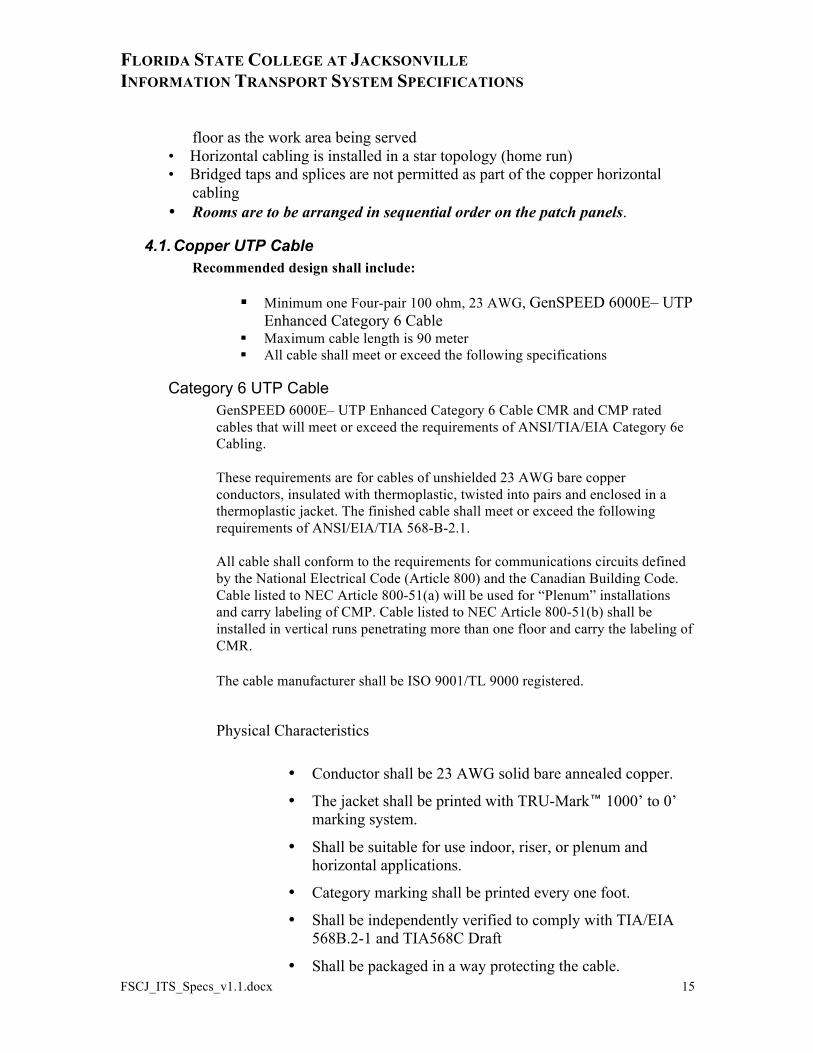
floor as the work area being served • Horizontal cabling is installed in a star topology (home run) • Bridged taps and splices are not permitted as part of the copper horizontal cabling • Rooms are to be arranged in sequential order on the patch panels.
4.1. Copper UTP Cable Recommended design shall include:
Minimum one Four-pair 100 ohm, 23 AWG, GenSPEED 6000E– UTP Enhanced Category 6 Cable
Maximum cable length is 90 meter All cable shall meet or exceed the following specifications
Category 6 UTP Cable GenSPEED 6000E– UTP Enhanced Category 6 Cable CMR and CMP rated cables that will meet or exceed the requirements of ANSI/TIA/EIA Category 6e Cabling.
These requirements are for cables of unshielded 23 AWG bare copper conductors, insulated with thermoplastic, twisted into pairs and enclosed in a thermoplastic jacket. The finished cable shall meet or exceed the following requirements of ANSI/EIA/TIA 568-B-2.1.
All cable shall conform to the requirements for communications circuits defined by the National Electrical Code (Article 800) and the Canadian Building Code. Cable listed to NEC Article 800-51(a) will be used for “Plenum” installations and carry labeling of CMP. Cable listed to NEC Article 800-51(b) shall be installed in vertical runs penetrating more than one floor and carry the labeling of CMR.
The cable manufacturer shall be ISO 9001/TL 9000 registered.
Physical Characteristics
• Conductor shall be 23 AWG solid bare annealed copper.
• The jacket shall be printed with TRU-Mark™ 1000’ to 0’ marking system.
• Shall be suitable for use indoor, riser, or plenum and horizontal applications.
• Category marking shall be printed every one foot.
• Shall be independently verified to comply with TIA/EIA 568B.2-1 and TIA568C Draft
• Shall be packaged in a way protecting the cable.
FLORIDA STATE COLLEGE AT JACKSONVILLE INFORMATION TRANSPORT SYSTEM SPECIFICATIONS
FSCJ_ITS_Specs_v1.1.docx 16
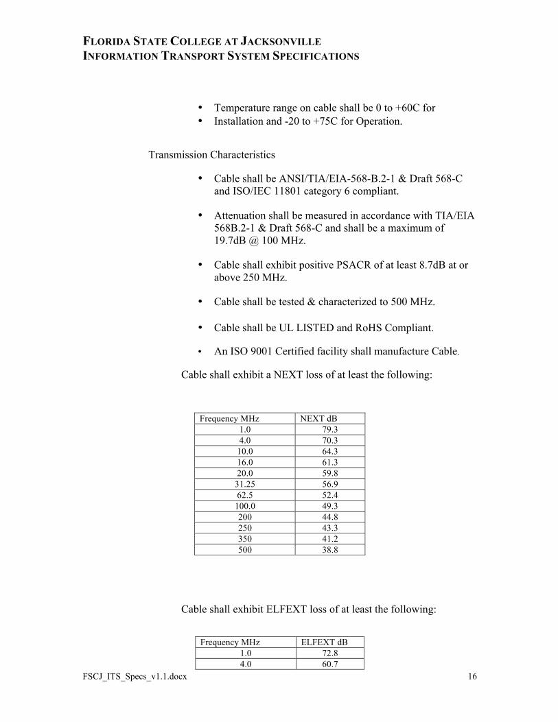
• Temperature range on cable shall be 0 to +60C for • Installation and -20 to +75C for Operation.
Transmission Characteristics
• Cable shall be ANSI/TIA/EIA-568-B.2-1 & Draft 568-C and ISO/IEC 11801 category 6 compliant.
• Attenuation shall be measured in accordance with TIA/EIA 568B.2-1 & Draft 568-C and shall be a maximum of 19.7dB @ 100 MHz.
• Cable shall exhibit positive PSACR of at least 8.7dB at or above 250 MHz.
• Cable shall be tested & characterized to 500 MHz.
• Cable shall be UL LISTED and RoHS Compliant.
• An ISO 9001 Certified facility shall manufacture Cable.
Cable shall exhibit a NEXT loss of at least the following:
Frequency MHz NEXT dB 1.0 79.3 4.0 70.3
10.0 64.3 16.0 61.3 20.0 59.8
31.25 56.9 62.5 52.4
100.0 49.3 200 44.8 250 43.3 350 41.2 500 38.8
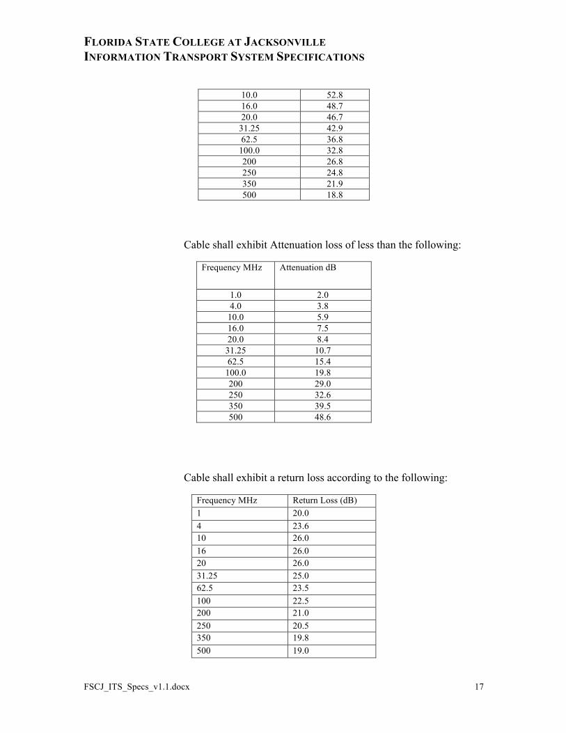
Cable shall exhibit ELFEXT loss of at least the following:
Frequency MHz ELFEXT dB 1.0 72.8 4.0 60.7
FLORIDA STATE COLLEGE AT JACKSONVILLE INFORMATION TRANSPORT SYSTEM SPECIFICATIONS
FSCJ_ITS_Specs_v1.1.docx 17
10.0 52.8 16.0 48.7 20.0 46.7
31.25 42.9 62.5 36.8
100.0 32.8 200 26.8 250 24.8 350 21.9 500 18.8
Cable shall exhibit Attenuation loss of less than the following:
Frequency MHz Attenuation dB
1.0 2.0 4.0 3.8
10.0 5.9 16.0 7.5 20.0 8.4
31.25 10.7 62.5 15.4
100.0 19.8 200 29.0 250 32.6 350 39.5 500 48.6
Cable shall exhibit a return loss according to the following:
Frequency MHz Return Loss (dB) 1 20.0 4 23.6 10 26.0 16 26.0 20 26.0 31.25 25.0 62.5 23.5 100 22.5 200 21.0 250 20.5 350 19.8 500 19.0
FLORIDA STATE COLLEGE AT JACKSONVILLE INFORMATION TRANSPORT SYSTEM SPECIFICATIONS
FSCJ_ITS_Specs_v1.1.docx 18
Approved Manufacture:
General Cable GenSPEED 6000E CMP: 7131900 or 7133940
4.2. Fiber Cable
Horizontal Distances - Optical Fiber Links When using optical fiber cables, any length of horizontal cables, work area cables, patch cords, and equipment cables is acceptable so long as the total of the combined lengths does not exceed manufacturers recommended distance outlined below per application.
Transmission is typically at 850 or 1300 nm for 50/125µm multimode optical fiber and at 1310 and 1550 nm for Single-mode.
Specifications ANSI/TIA/EIA-568-B.3 Horizontal fiber cable distribution systems: • The optical fiber cable shall consist of a minimum of two
50/125µm or 8.3/125µm optical fibers enclosed by a protective sheath
• The cable will be capable of supporting 1 gig and 10 gig applications
• The optical fiber shall be 50/125µm multimode or 8.3/125µm single-mode
• The mechanical and environmental specification for the optical fiber cable will be in accordance with ANSI/ICEA-S-83-596.
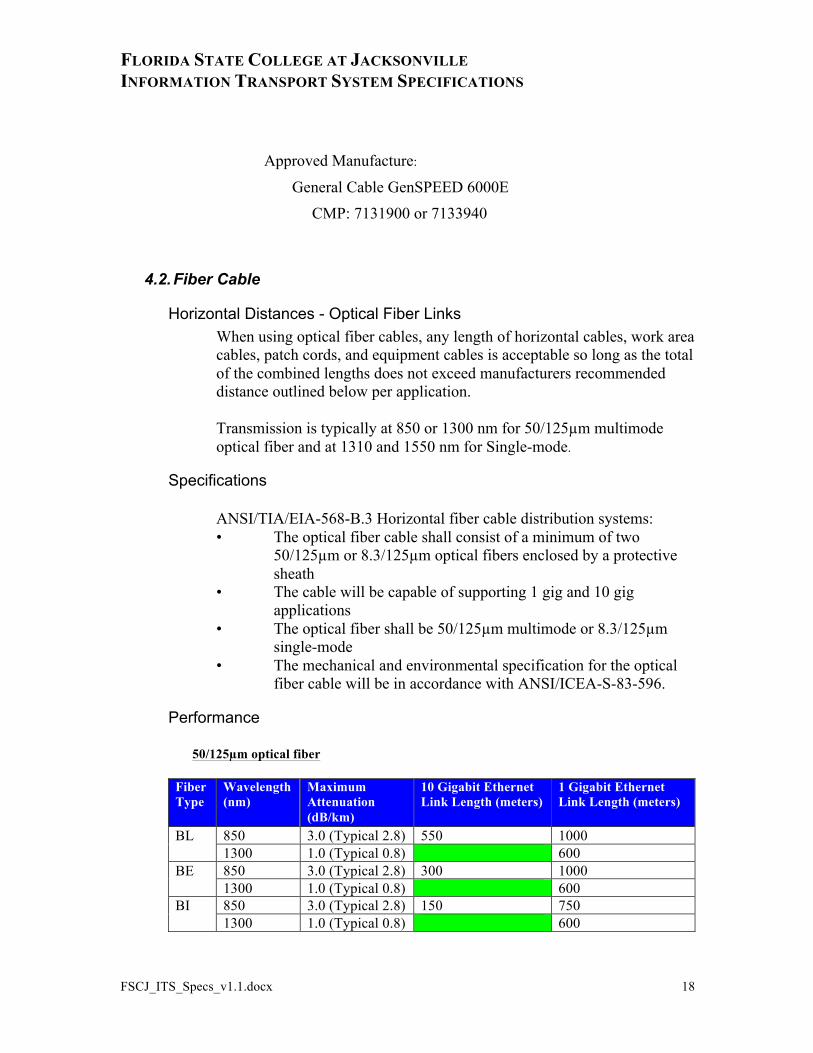
Performance
50/125µm optical fiber
Fiber Type
Wavelength (nm)
Maximum Attenuation (dB/km)
10 Gigabit Ethernet Link Length (meters)
1 Gigabit Ethernet Link Length (meters)
BL 850 3.0 (Typical 2.8) 550 1000 1300 1.0 (Typical 0.8) 600 BE 850 3.0 (Typical 2.8) 300 1000 1300 1.0 (Typical 0.8) 600 BI 850 3.0 (Typical 2.8) 150 750 1300 1.0 (Typical 0.8) 600
FLORIDA STATE COLLEGE AT JACKSONVILLE INFORMATION TRANSPORT SYSTEM SPECIFICATIONS
FSCJ_ITS_Specs_v1.1.docx 19
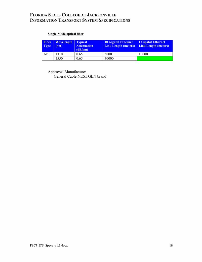
Single-Mode optical fiber
Fiber Type
Wavelength (nm)
Typical Attenuation (dB/km)
10 Gigabit Ethernet Link Length (meters)
1 Gigabit Ethernet Link Length (meters)
AP 1310 0.65 5000 10000 1550 0.65 30000
Approved Manufacture: General Cable NEXTGEN brand
FLORIDA STATE COLLEGE AT JACKSONVILLE INFORMATION TRANSPORT SYSTEM SPECIFICATIONS
FSCJ_ITS_Specs_v1.1.docx 20
5. Telecommunications Room The telecommunications room (TR) includes those products that connect the networking equipment to the horizontal and backbone cabling subsystems. These products include termination hardware (connectors and patch cords), racks, cable management products and cable routing products.
5.1. Cable Termination Hardware Each horizontal or backbone cabling run will be terminated using appropriate connectors or connecting blocks depending upon the cable type. Matching patch cords will be used to perform cross-connect activities or to connect into the networking/voice hardware.
5.1.1. Category 6 Unshielded Twisted Pair UTP Four-pair Category 6 cabling shall be terminated onto modular patch panels.
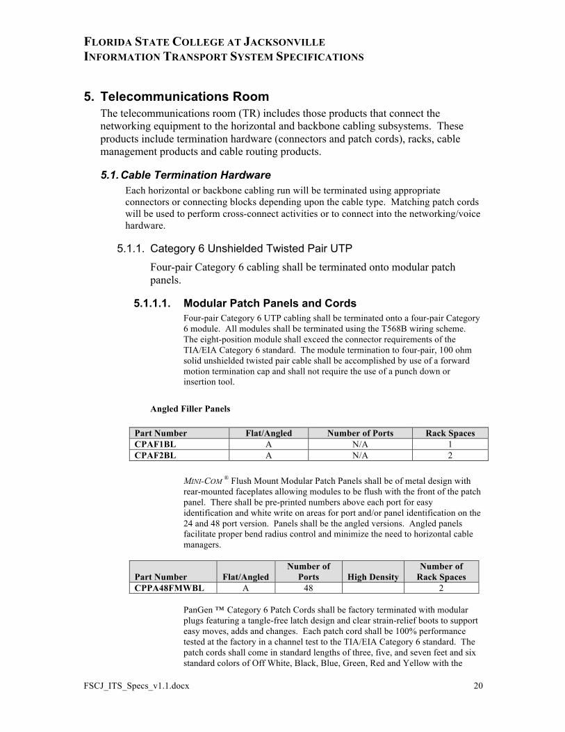
5.1.1.1. Modular Patch Panels and Cords Four-pair Category 6 UTP cabling shall be terminated onto a four-pair Category 6 module. All modules shall be terminated using the T568B wiring scheme. The eight-position module shall exceed the connector requirements of the TIA/EIA Category 6 standard. The module termination to four-pair, 100 ohm solid unshielded twisted pair cable shall be accomplished by use of a forward motion termination cap and shall not require the use of a punch down or insertion tool.
Angled Filler Panels
Part Number Flat/Angled Number of Ports Rack Spaces CPAF1BL A N/A 1 CPAF2BL A N/A 2
MINI-COM ® Flush Mount Modular Patch Panels shall be of metal design with rear-mounted faceplates allowing modules to be flush with the front of the patch panel. There shall be pre-printed numbers above each port for easy identification and white write on areas for port and/or panel identification on the 24 and 48 port version. Panels shall be the angled versions. Angled panels facilitate proper bend radius control and minimize the need to horizontal cable managers.
Part Number Flat/Angled Number of
Ports High Density Number of
Rack Spaces CPPA48FMWBL A 48 2
PanGen ™
Category 6 Patch Cords shall be factory terminated with modular plugs featuring a tangle-free latch design and clear strain-relief boots to support easy moves, adds and changes. Each patch cord shall be 100% performance tested at the factory in a channel test to the TIA/EIA Category 6 standard. The patch cords shall come in standard lengths of three, five, and seven feet and six standard colors of Off White, Black, Blue, Green, Red and Yellow with the
FLORIDA STATE COLLEGE AT JACKSONVILLE INFORMATION TRANSPORT SYSTEM SPECIFICATIONS
FSCJ_ITS_Specs_v1.1.docx 21
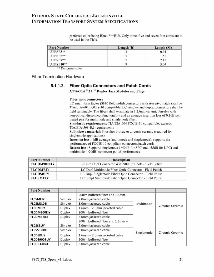
preferred color being Blue (**=BU). Only three, five and seven foot cords are to be used in the TR’s.
Part Number Length (ft) Length (M) UTPSP3** 3 0.91 UTPSP5** 5 1.52 UTPSP7** 7 2.13 UTPSP10** 9 3.04
** Designates color
Fiber Termination Hardware
5.1.1.2. Fiber Optic Connectors and Patch Cords MINI-COM ® LC ® Duplex Jack Modules and Plugs Fiber optic connectors LC small form factor (SFF) field polish connectors with rear pivot latch shall be TIA/EIA-604 FOCIS-10 compatible. LC simplex and duplex connectors shall be field terminable. The fibers shall terminate in 1.25mm ceramic ferrules with non-optical disconnect functionality and an average insertion loss of 0.1dB per mated pair for multimode and singlemode fiber. Standards requirements: TIA/EIA-604 FOCIS-10 compatible; exceeds TIA/EIA-568-B.3 requirements Split sleeve material: Phosphor bronze or zirconia ceramic (required for singlemode applications) Insertion loss: .1dB average (multimode and singlemode); supports the performance of FOCIS-10 compliant connectors/patch cords Return loss: Supports singlemode (>40dB for SPC and >55dB for UPC) and multimode (>20dB) connector polish performance
Part Number Description FLCDM900EIY LC mm Dupl Connector With 900µm Boots - Field Polish
FLCDMEIY LC Dupl Multimode Fiber Optic Connector - Field Polish FLCDSBUY LC Dupl Singlemode Fiber Optic Connector - Field Polish FLCSMEIY LC Simpl Multimode Fiber Optic Connector - Field Polish
Part Number
FLCSMEIY Simplex 900ìm buffered fiber and 1.6mm – 2.0mm jacketed cable
Multimode Zirconia Ceramic
FLCSM3.0EI Simplex 3.0mm jacketed cable FLCDMEIY Duplex 1.6mm – 2.0mm jacketed cable FLCDM900EIY Duplex 900ìm buffered fiber FLCDM3.0EI Duplex 3.0mm jacketed cable
FLCSSBUY Simplex 900ìm buffered fiber and 1.6mm – 2.0mm jacketed cable
Singlemode Zirconia Ceramic FLCSS3.0BU Simplex 3.0mm jacketed cable FLCDSBUY FLCDS900BUY
Duplex Duplex
1.6mm – 2.0mm jacketed cable 900ìm buffered fiber
FLCDS3.0BU Duplex 3.0mm jacketed cable
FLORIDA STATE COLLEGE AT JACKSONVILLE INFORMATION TRANSPORT SYSTEM SPECIFICATIONS
FSCJ_ITS_Specs_v1.1.docx 22
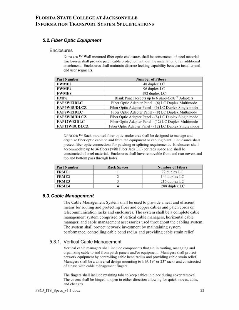
5.2. Fiber Optic Equipment
Enclosures OPTICOM ™ Wall mounted fiber optic enclosures shall be constructed of steel material. Enclosures shall provide patch cable protection without the installation of an additional attachment. Enclosures shall maintain discrete locking capability between installer and end user segments.
Part Number Number of Fibers FWME2 48 duplex LC FWME4 96 duplex LC FWME8 192 duplex LC FMP6 Blank Panel accepts up to 6 MINI-COM ® Adapters FAP6WEIDLC Fiber Optic Adapter Panel - (6) LC Duplex Multimode FAP6WBUDLCZ Fiber Optic Adapter Panel - (6) LC Duplex Single mode FAP8WEIDLC Fiber Optic Adapter Panel - (8) LC Duplex Multimode FAP8WBUDLCZ Fiber Optic Adapter Panel - (8) LC Duplex Single mode FAP12WEIDLC Fiber Optic Adapter Panel - (12) LC Duplex Multimode FAP12WBUDLCZ Fiber Optic Adapter Panel - (12) LC Duplex Single mode
OPTICOM ™ Rack mounted fiber optic enclosures shall be designed to manage and organize fiber optic cable to and from the equipment or cabling plant. Enclosures shall protect fiber optic connections for patching or splicing requirements. Enclosures shall accommodate up to 36 fibers (with Fiber Jack LC) per rack space and shall be constructed of steel material. Enclosures shall have removable front and rear covers and top and bottom pass through holes.
Part Number Rack Spaces Number of Fibers FRME1 1 72 duplex LC FRME2 2 144 duplex LC FRME3 3 216 duplex LC FRME4 4 288 duplex LC
5.3. Cable Management The Cable Management System shall be used to provide a neat and efficient means for routing and protecting fiber and copper cables and patch cords on telecommunication racks and enclosures. The system shall be a complete cable management system comprised of vertical cable managers, horizontal cable manager, and cable management accessories used throughout the cabling system. The system shall protect network investment by maintaining system performance, controlling cable bend radius and providing cable strain relief.
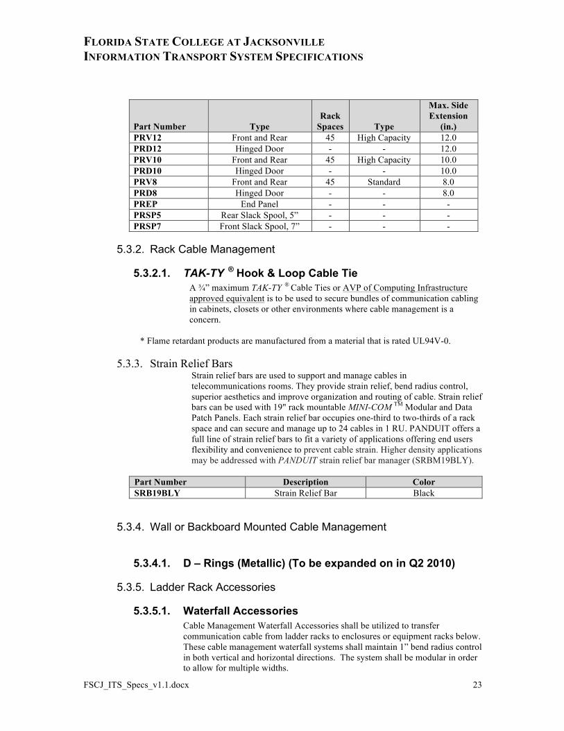
5.3.1. Vertical Cable Management Vertical cable managers shall include components that aid in routing, managing and organizing cable to and from patch panels and/or equipment. Managers shall protect network equipment by controlling cable bend radius and providing cable strain relief. Managers shall be a universal design mounting to EIA 19" or 23" racks and constructed of a base with cable management fingers. The fingers shall include retaining tabs to keep cables in place during cover removal. The covers shall be hinged to open in either direction allowing for quick moves, adds, and changes.
FLORIDA STATE COLLEGE AT JACKSONVILLE INFORMATION TRANSPORT SYSTEM SPECIFICATIONS
FSCJ_ITS_Specs_v1.1.docx 23
Part Number Type Rack
Spaces Type
Max. Side Extension
(in.) PRV12 Front and Rear 45 High Capacity 12.0 PRD12 Hinged Door - - 12.0 PRV10 Front and Rear 45 High Capacity 10.0 PRD10 Hinged Door - - 10.0 PRV8 Front and Rear 45 Standard 8.0 PRD8 Hinged Door - - 8.0 PREP End Panel - - - PRSP5 Rear Slack Spool, 5” - - - PRSP7 Front Slack Spool, 7” - - -
5.3.2. Rack Cable Management
5.3.2.1. TAK-TY ® Hook & Loop Cable Tie A ¾” maximum TAK-TY ®
Cable Ties or AVP of Computing Infrastructure approved equivalent is to be used to secure bundles of communication cabling in cabinets, closets or other environments where cable management is a concern.
* Flame retardant products are manufactured from a material that is rated UL94V-0.
5.3.3. Strain Relief Bars Strain relief bars are used to support and manage cables in telecommunications rooms. They provide strain relief, bend radius control, superior aesthetics and improve organization and routing of cable. Strain relief bars can be used with 19" rack mountable MINI-COM TM Modular and Data Patch Panels. Each strain relief bar occupies one-third to two-thirds of a rack space and can secure and manage up to 24 cables in 1 RU. PANDUIT offers a full line of strain relief bars to fit a variety of applications offering end users flexibility and convenience to prevent cable strain. Higher density applications may be addressed with PANDUIT strain relief bar manager (SRBM19BLY).
Part Number Description Color SRB19BLY Strain Relief Bar Black
5.3.4. Wall or Backboard Mounted Cable Management
5.3.4.1. D – Rings (Metallic) (To be expanded on in Q2 2010)
5.3.5. Ladder Rack Accessories
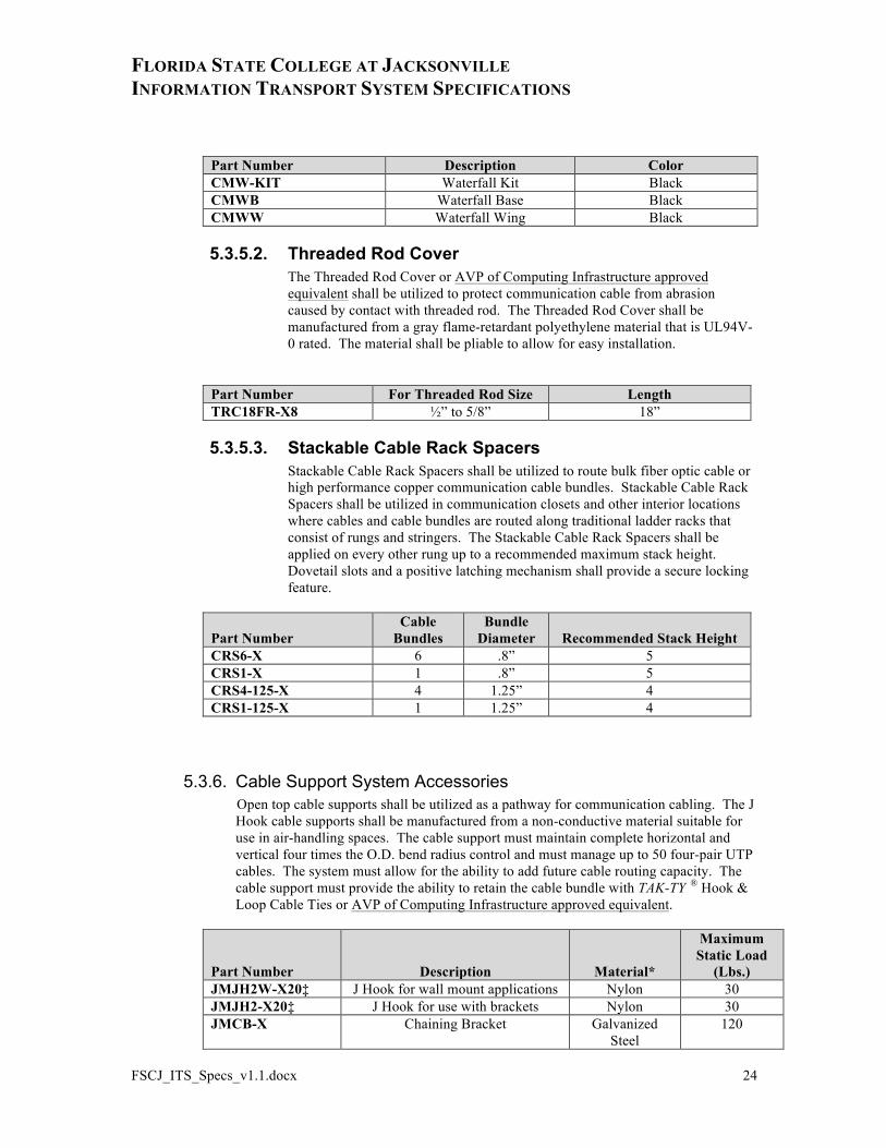
5.3.5.1. Waterfall Accessories Cable Management Waterfall Accessories shall be utilized to transfer communication cable from ladder racks to enclosures or equipment racks below. These cable management waterfall systems shall maintain 1” bend radius control in both vertical and horizontal directions. The system shall be modular in order to allow for multiple widths.
FLORIDA STATE COLLEGE AT JACKSONVILLE INFORMATION TRANSPORT SYSTEM SPECIFICATIONS
FSCJ_ITS_Specs_v1.1.docx 24
Part Number Description Color CMW-KIT Waterfall Kit Black CMWB Waterfall Base Black CMWW Waterfall Wing Black
5.3.5.2. Threaded Rod Cover The Threaded Rod Cover or AVP of Computing Infrastructure approved equivalent shall be utilized to protect communication cable from abrasion caused by contact with threaded rod. The Threaded Rod Cover shall be manufactured from a gray flame-retardant polyethylene material that is UL94V-0 rated. The material shall be pliable to allow for easy installation.
Part Number For Threaded Rod Size Length TRC18FR-X8 ½” to 5/8” 18”
5.3.5.3. Stackable Cable Rack Spacers Stackable Cable Rack Spacers shall be utilized to route bulk fiber optic cable or high performance copper communication cable bundles. Stackable Cable Rack Spacers shall be utilized in communication closets and other interior locations where cables and cable bundles are routed along traditional ladder racks that consist of rungs and stringers. The Stackable Cable Rack Spacers shall be applied on every other rung up to a recommended maximum stack height. Dovetail slots and a positive latching mechanism shall provide a secure locking feature.
Part Number Cable
Bundles Bundle
Diameter Recommended Stack Height CRS6-X 6 .8” 5 CRS1-X 1 .8” 5 CRS4-125-X 4 1.25” 4 CRS1-125-X 1 1.25” 4
5.3.6. Cable Support System Accessories Open top cable supports shall be utilized as a pathway for communication cabling. The J Hook cable supports shall be manufactured from a non-conductive material suitable for use in air-handling spaces. The cable support must maintain complete horizontal and vertical four times the O.D. bend radius control and must manage up to 50 four-pair UTP cables. The system must allow for the ability to add future cable routing capacity. The cable support must provide the ability to retain the cable bundle with TAK-TY ® Hook & Loop Cable Ties or AVP of Computing Infrastructure approved equivalent.
Part Number Description Material*
Maximum Static Load
(Lbs.) JMJH2W-X20‡ J Hook for wall mount applications Nylon 30 JMJH2-X20‡ J Hook for use with brackets Nylon 30 JMCB-X Chaining Bracket Galvanized
Steel 120
FLORIDA STATE COLLEGE AT JACKSONVILLE INFORMATION TRANSPORT SYSTEM SPECIFICATIONS
FSCJ_ITS_Specs_v1.1.docx 25
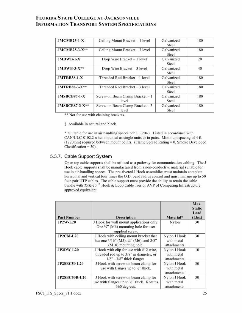
JMCMB25-1-X Ceiling Mount Bracket – 1 level Galvanized Steel
180
JMCMB25-3-X** Ceiling Mount Bracket – 3 level Galvanized Steel
180
JMDWB-1-X Drop Wire Bracket – 1 level Galvanized Steel
20
JMDWB-3-X** Drop Wire Bracket – 3 level Galvanized Steel
40
JMTRB38-1-X Threaded Rod Bracket – 1 level Galvanized Steel
180
JMTRB38-3-X** Threaded Rod Bracket – 3 level Galvanized Steel
180
JMSBCB87-1-X Screw-on Beam Clamp Bracket – 1 level
Galvanized Steel
180
JMSBCB87-3-X** Screw-on Beam Clamp Bracket – 3 level
Galvanized Steel
180
** Not for use with chaining brackets. ‡ Available in natural and black. * Suitable for use in air handling spaces per UL 2043. Listed in accordance with CAN/ULC S102.2 when mounted as single units or in pairs. Minimum spacing of 4 ft. (1220mm) required between mount points. (Flame Spread Rating = 0, Smoke Developed Classification = 30).
5.3.7. Cable Support System Open top cable supports shall be utilized as a pathway for communication cabling. The J Hook cable supports shall be manufactured from a non-conductive material suitable for use in air-handling spaces. The pre-riveted J Hook assemblies must maintain complete horizontal and vertical four times the O.D. bend radius control and must manage up to 50 four-pair UTP cables. The cable support must provide the ability to retain the cable bundle with TAK-TY ® Hook & Loop Cable Ties or AVP of Computing Infrastructure approved equivalent.
Part Number Description Material*
Max. Static Load (Lbs.)
JP2W-L20
J Hook for wall mount applications only. One ¼” (M6) mounting hole for user
supplied screw.
Nylon 30
JP2CM-L20 J Hook with ceiling mount bracket that has one 3/16” (M5), ¼” (M6), and 3/8”
(M10) mounting hole.
Nylon J Hook with metal
attachments
30
JP2DW-L20 J Hook with clip for use with #12 wire, threaded rod up to 3/8” in diameter, or
1/8” –3/8” thick flanges.
Nylon J Hook with metal
attachments
10
JP2SBC50-L20 J Hook with screw-on beam clamp for use with flanges up to ½” thick.
Nylon J Hook with metal
attachments
30
JP2SBC50R-L20 J Hook with screw-on beam clamp for use with flanges up to ½” thick. Rotates
360 degrees.
Nylon J Hook with metal
attachments
30
FLORIDA STATE COLLEGE AT JACKSONVILLE INFORMATION TRANSPORT SYSTEM SPECIFICATIONS
FSCJ_ITS_Specs_v1.1.docx 26
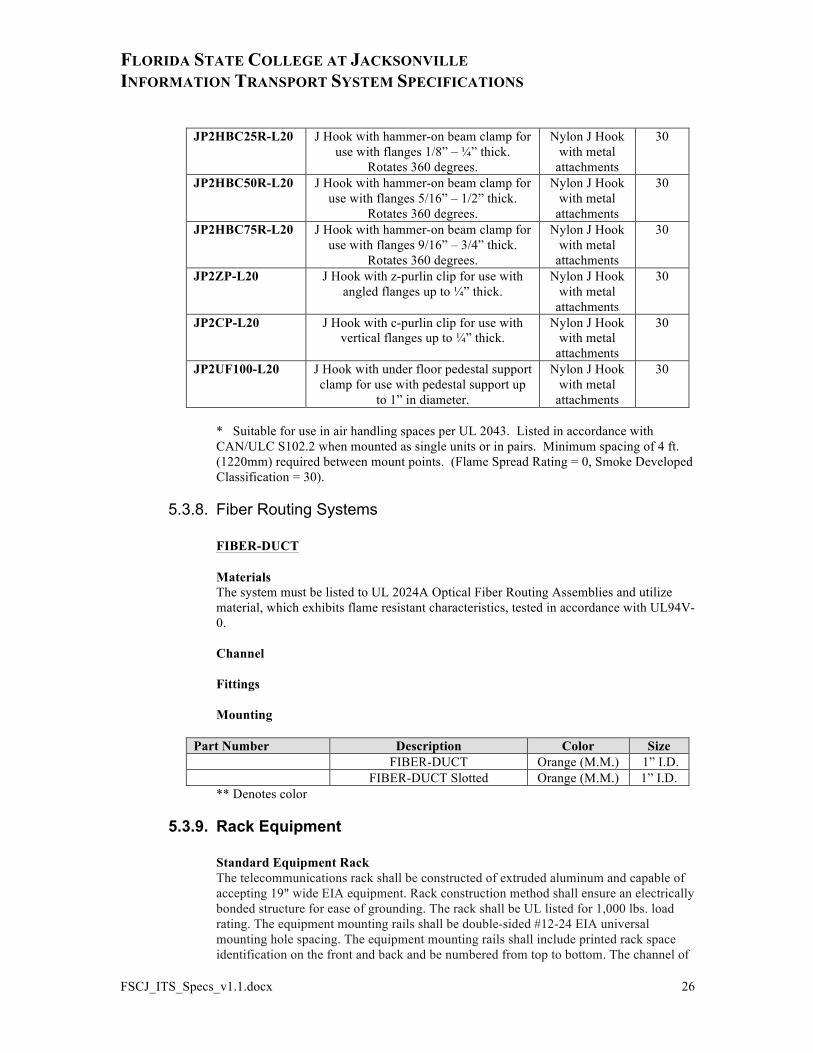
JP2HBC25R-L20 J Hook with hammer-on beam clamp for use with flanges 1/8” – ¼” thick.
Rotates 360 degrees.
Nylon J Hook with metal
attachments
30
JP2HBC50R-L20 J Hook with hammer-on beam clamp for use with flanges 5/16” – 1/2” thick.
Rotates 360 degrees.
Nylon J Hook with metal
attachments
30
JP2HBC75R-L20 J Hook with hammer-on beam clamp for use with flanges 9/16” – 3/4” thick.
Rotates 360 degrees.
Nylon J Hook with metal
attachments
30
JP2ZP-L20 J Hook with z-purlin clip for use with angled flanges up to ¼” thick.
Nylon J Hook with metal
attachments
30
JP2CP-L20 J Hook with c-purlin clip for use with vertical flanges up to ¼” thick.
Nylon J Hook with metal
attachments
30
JP2UF100-L20 J Hook with under floor pedestal support clamp for use with pedestal support up
to 1” in diameter.
Nylon J Hook with metal
attachments
30
* Suitable for use in air handling spaces per UL 2043. Listed in accordance with CAN/ULC S102.2 when mounted as single units or in pairs. Minimum spacing of 4 ft. (1220mm) required between mount points. (Flame Spread Rating = 0, Smoke Developed Classification = 30).
5.3.8. Fiber Routing Systems
FIBER-DUCT
Materials The system must be listed to UL 2024A Optical Fiber Routing Assemblies and utilize material, which exhibits flame resistant characteristics, tested in accordance with UL94V-0. Channel Fittings Mounting
Part Number Description Color Size FIBER-DUCT Orange (M.M.) 1” I.D. FIBER-DUCT Slotted Orange (M.M.) 1” I.D.
** Denotes color
5.3.9. Rack Equipment Standard Equipment Rack
The telecommunications rack shall be constructed of extruded aluminum and capable of accepting 19" wide EIA equipment. Rack construction method shall ensure an electrically bonded structure for ease of grounding. The rack shall be UL listed for 1,000 lbs. load rating. The equipment mounting rails shall be double-sided #12-24 EIA universal mounting hole spacing. The equipment mounting rails shall include printed rack space identification on the front and back and be numbered from top to bottom. The channel of

FLORIDA STATE COLLEGE AT JACKSONVILLE INFORMATION TRANSPORT SYSTEM SPECIFICATIONS
FSCJ_ITS_Specs_v1.1.docx 27
the rack shall be capable of mounting NETRUNNERTM or PATCHRUNNERTM Vertical Cable Managers. 24 #12-24 mounting screws shall be included with the rack.
Part Number Description Color CMR19x84 Standard 19”x 84” 2 Post
Equipment Rack Black
FLORIDA STATE COLLEGE AT JACKSONVILLE INFORMATION TRANSPORT SYSTEM SPECIFICATIONS
FSCJ_ITS_Specs_v1.1.docx 28
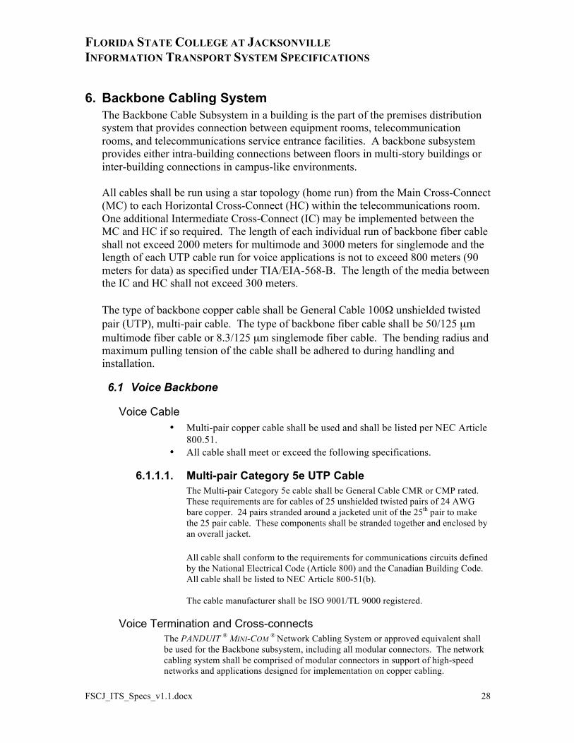
6. Backbone Cabling System The Backbone Cable Subsystem in a building is the part of the premises distribution system that provides connection between equipment rooms, telecommunication rooms, and telecommunications service entrance facilities. A backbone subsystem provides either intra-building connections between floors in multi-story buildings or inter-building connections in campus-like environments.
All cables shall be run using a star topology (home run) from the Main Cross-Connect (MC) to each Horizontal Cross-Connect (HC) within the telecommunications room. One additional Intermediate Cross-Connect (IC) may be implemented between the MC and HC if so required. The length of each individual run of backbone fiber cable shall not exceed 2000 meters for multimode and 3000 meters for singlemode and the length of each UTP cable run for voice applications is not to exceed 800 meters (90 meters for data) as specified under TIA/EIA-568-B. The length of the media between the IC and HC shall not exceed 300 meters.
The type of backbone copper cable shall be General Cable 100Ω unshielded twisted pair (UTP), multi-pair cable. The type of backbone fiber cable shall be 50/125 µm multimode fiber cable or 8.3/125 µm singlemode fiber cable. The bending radius and maximum pulling tension of the cable shall be adhered to during handling and installation.
6.1 Voice Backbone
Voice Cable • Multi-pair copper cable shall be used and shall be listed per NEC Article
800.51. • All cable shall meet or exceed the following specifications.
6.1.1.1. Multi-pair Category 5e UTP Cable The Multi-pair Category 5e cable shall be General Cable CMR or CMP rated. These requirements are for cables of 25 unshielded twisted pairs of 24 AWG bare copper. 24 pairs stranded around a jacketed unit of the 25th pair to make the 25 pair cable. These components shall be stranded together and enclosed by an overall jacket.
All cable shall conform to the requirements for communications circuits defined by the National Electrical Code (Article 800) and the Canadian Building Code. All cable shall be listed to NEC Article 800-51(b).
The cable manufacturer shall be ISO 9001/TL 9000 registered.
Voice Termination and Cross-connects The PANDUIT ® MINI-COM ® Network Cabling System or approved equivalent shall be used for the Backbone subsystem, including all modular connectors. The network cabling system shall be comprised of modular connectors in support of high-speed networks and applications designed for implementation on copper cabling.
FLORIDA STATE COLLEGE AT JACKSONVILLE INFORMATION TRANSPORT SYSTEM SPECIFICATIONS
FSCJ_ITS_Specs_v1.1.docx 29
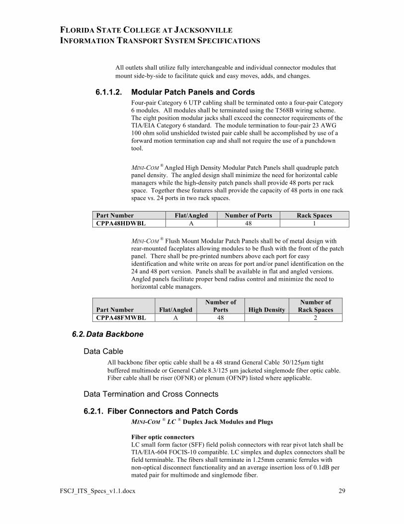
All outlets shall utilize fully interchangeable and individual connector modules that mount side-by-side to facilitate quick and easy moves, adds, and changes.
6.1.1.2. Modular Patch Panels and Cords Four-pair Category 6 UTP cabling shall be terminated onto a four-pair Category 6 modules. All modules shall be terminated using the T568B wiring scheme. The eight position modular jacks shall exceed the connector requirements of the TIA/EIA Category 6 standard. The module termination to four-pair 23 AWG 100 ohm solid unshielded twisted pair cable shall be accomplished by use of a forward motion termination cap and shall not require the use of a punchdown tool.
MINI-COM ® Angled High Density Modular Patch Panels shall quadruple patch panel density. The angled design shall minimize the need for horizontal cable managers while the high-density patch panels shall provide 48 ports per rack space. Together these features shall provide the capacity of 48 ports in one rack space vs. 24 ports in two rack spaces.
Part Number Flat/Angled Number of Ports Rack Spaces CPPA48HDWBL A 48 1
MINI-COM ® Flush Mount Modular Patch Panels shall be of metal design with rear-mounted faceplates allowing modules to be flush with the front of the patch panel. There shall be pre-printed numbers above each port for easy identification and white write on areas for port and/or panel identification on the 24 and 48 port version. Panels shall be available in flat and angled versions. Angled panels facilitate proper bend radius control and minimize the need to horizontal cable managers.
Part Number Flat/Angled Number of
Ports High Density Number of
Rack Spaces CPPA48FMWBL A 48 2
6.2. Data Backbone
Data Cable All backbone fiber optic cable shall be a 48 strand General Cable 50/125µm tight buffered multimode or General Cable 8.3/125 µm jacketed singlemode fiber optic cable. Fiber cable shall be riser (OFNR) or plenum (OFNP) listed where applicable.
Data Termination and Cross Connects
6.2.1. Fiber Connectors and Patch Cords MINI-COM ® LC ® Duplex Jack Modules and Plugs Fiber optic connectors LC small form factor (SFF) field polish connectors with rear pivot latch shall be TIA/EIA-604 FOCIS-10 compatible. LC simplex and duplex connectors shall be field terminable. The fibers shall terminate in 1.25mm ceramic ferrules with non-optical disconnect functionality and an average insertion loss of 0.1dB per mated pair for multimode and singlemode fiber.
FLORIDA STATE COLLEGE AT JACKSONVILLE INFORMATION TRANSPORT SYSTEM SPECIFICATIONS
FSCJ_ITS_Specs_v1.1.docx 30
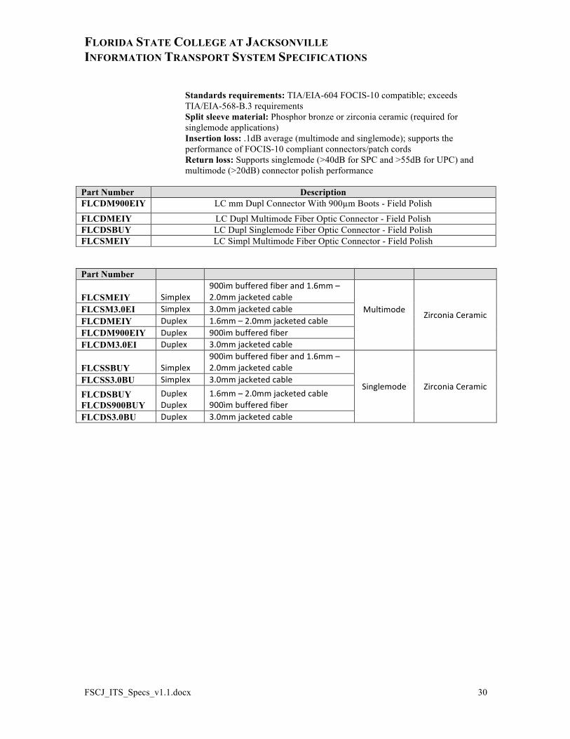
Standards requirements: TIA/EIA-604 FOCIS-10 compatible; exceeds TIA/EIA-568-B.3 requirements Split sleeve material: Phosphor bronze or zirconia ceramic (required for singlemode applications) Insertion loss: .1dB average (multimode and singlemode); supports the performance of FOCIS-10 compliant connectors/patch cords Return loss: Supports singlemode (>40dB for SPC and >55dB for UPC) and multimode (>20dB) connector polish performance
Part Number Description FLCDM900EIY LC mm Dupl Connector With 900µm Boots - Field Polish
FLCDMEIY LC Dupl Multimode Fiber Optic Connector - Field Polish FLCDSBUY LC Dupl Singlemode Fiber Optic Connector - Field Polish FLCSMEIY LC Simpl Multimode Fiber Optic Connector - Field Polish
Part Number
FLCSMEIY Simplex 900ìm buffered fiber and 1.6mm – 2.0mm jacketed cable
Multimode Zirconia Ceramic FLCSM3.0EI Simplex 3.0mm jacketed cable
FLCDMEIY Duplex 1.6mm – 2.0mm jacketed cable FLCDM900EIY Duplex 900ìm buffered fiber FLCDM3.0EI Duplex 3.0mm jacketed cable
FLCSSBUY Simplex 900ìm buffered fiber and 1.6mm – 2.0mm jacketed cable
Singlemode Zirconia Ceramic FLCSS3.0BU Simplex 3.0mm jacketed cable
FLCDSBUY FLCDS900BUY
Duplex Duplex
1.6mm – 2.0mm jacketed cable 900ìm buffered fiber
FLCDS3.0BU Duplex 3.0mm jacketed cable
FLORIDA STATE COLLEGE AT JACKSONVILLE INFORMATION TRANSPORT SYSTEM SPECIFICATIONS
FSCJ_ITS_Specs_v1.1.docx 31
7. Identification
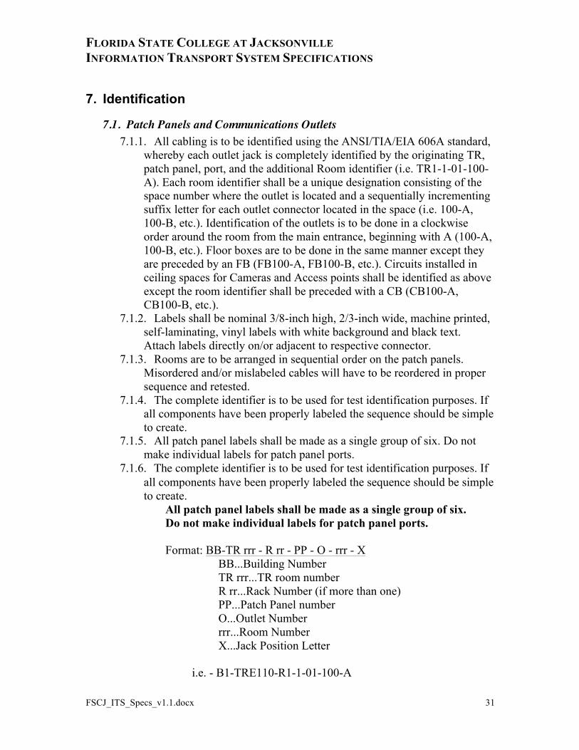
7.1. Patch Panels and Communications Outlets 7.1.1. All cabling is to be identified using the ANSI/TIA/EIA 606A standard,
whereby each outlet jack is completely identified by the originating TR, patch panel, port, and the additional Room identifier (i.e. TR1-1-01-100- A). Each room identifier shall be a unique designation consisting of the space number where the outlet is located and a sequentially incrementing suffix letter for each outlet connector located in the space (i.e. 100-A, 100-B, etc.). Identification of the outlets is to be done in a clockwise order around the room from the main entrance, beginning with A (100-A, 100-B, etc.). Floor boxes are to be done in the same manner except they are preceded by an FB (FB100-A, FB100-B, etc.). Circuits installed in ceiling spaces for Cameras and Access points shall be identified as above except the room identifier shall be preceded with a CB (CB100-A, CB100-B, etc.).
7.1.2. Labels shall be nominal 3/8-inch high, 2/3-inch wide, machine printed, self-laminating, vinyl labels with white background and black text. Attach labels directly on/or adjacent to respective connector.
7.1.3. Rooms are to be arranged in sequential order on the patch panels. Misordered and/or mislabeled cables will have to be reordered in proper sequence and retested.
7.1.4. The complete identifier is to be used for test identification purposes. If all components have been properly labeled the sequence should be simple to create.
7.1.5. All patch panel labels shall be made as a single group of six. Do not make individual labels for patch panel ports.
7.1.6. The complete identifier is to be used for test identification purposes. If all components have been properly labeled the sequence should be simple to create.
All patch panel labels shall be made as a single group of six. Do not make individual labels for patch panel ports.
Format: BB-TR rrr - R rr - PP - O - rrr - X
BB...Building Number TR rrr...TR room number R rr...Rack Number (if more than one) PP...Patch Panel number O...Outlet Number rrr...Room Number X...Jack Position Letter
i.e. - B1-TRE110-R1-1-01-100-A
FLORIDA STATE COLLEGE AT JACKSONVILLE INFORMATION TRANSPORT SYSTEM SPECIFICATIONS
FSCJ_ITS_Specs_v1.1.docx 32
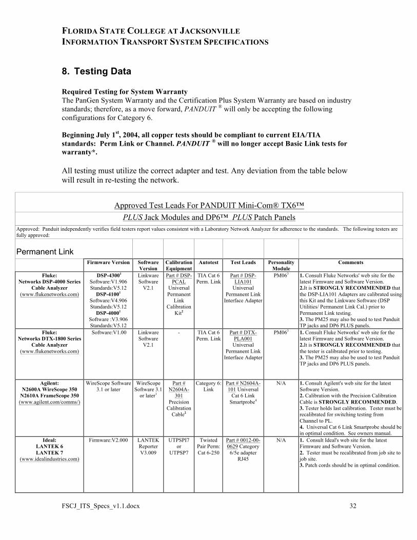
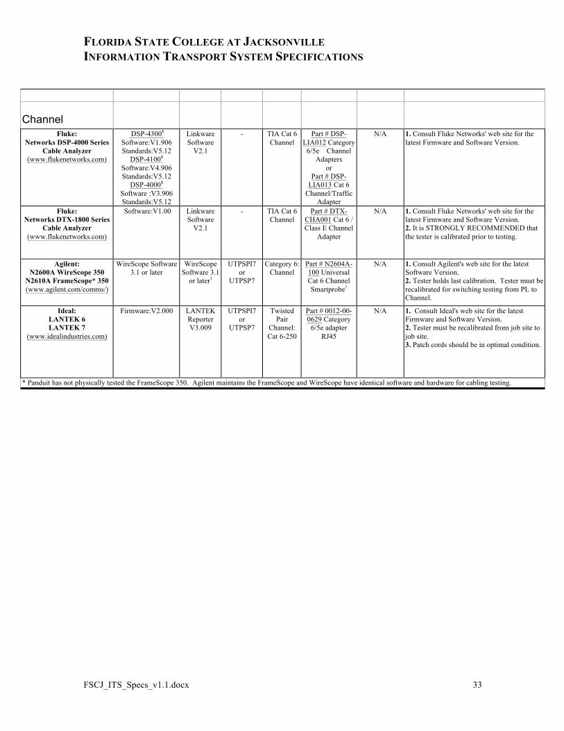
8. Testing Data Required Testing for System Warranty The PanGen System Warranty and the Certification Plus System Warranty are based on industry standards; therefore, as a move forward, PANDUIT ® will only be accepting the following configurations for Category 6. Beginning July 1st, 2004, all copper tests should be compliant to current EIA/TIA standards: Perm Link or Channel. PANDUIT ® will no longer accept Basic Link tests for warranty*. All testing must utilize the correct adapter and test. Any deviation from the table below will result in re-testing the network.
Approved Test Leads For PANDUIT Mini-Com® TX6™ PLUS Jack Modules and DP6™ PLUS Patch Panels
Approved: Panduit independently verifies field testers report values consistent with a Laboratory Network Analyzer for adherence to the standards. The following testers are fully approved:
Permanent Link
Firmware Version Software Version
Calibration Equipment
Autotest Test Leads Personality Module
Comments
Fluke: Networks DSP-4000 Series
Cable Analyzer (www.flukenetworks.com)
DSP-43001 Software:V1.906 Standards:V5.12
DSP-41001 Software:V4.906 Standards:V5.12
DSP-40001 Software :V3.906 Standards:V5.12
Linkware Software
V2.1
Part # DSP-PCAL
Universal Permanent
Link Calibration
Kit2
TIA Cat 6 Perm. Link
Part # DSP-LIA101
Universal Permanent Link
Interface Adapter
PM063 1. Consult Fluke Networks' web site for the latest Firmware and Software Version. 2.It is STRONGLY RECOMMENDED that the DSP-LIA101 Adapters are calibrated using this Kit and the Linkware Software (DSP Utilities/ Permanent Link Cal.) prior to Permanent Link testing. 3. The PM25 may also be used to test Panduit TP jacks and DP6 PLUS panels.
Fluke: Networks DTX-1800 Series
Cable Analyzer (www.flukenetworks.com)
Software:V1.00 Linkware Software
V2.1
- TIA Cat 6 Perm. Link
Part # DTX-PLA001
Universal Permanent Link
Interface Adapter
PM063 1. Consult Fluke Networks' web site for the latest Firmware and Software Version. 2.It is STRONGLY RECOMMENDED that the tester is calibrated prior to testing. 3. The PM25 may also be used to test Panduit TP jacks and DP6 PLUS panels.
Agilent: N2600A WireScope 350
N2610A FrameScope 350 (www.agilent.com/comms/)
WireScope Software 3.1 or later
WireScope Software 3.1
or later1
Part # N2604A-
301 Precision
Calibration Cable2
Category 6: Link
Part # N2604A-101 Universal
Cat 6 Link Smartprobe4
N/A 1. Consult Agilent's web site for the latest Software Version. 2. Calibration with the Precision Calibration Cable is STRONGLY RECOMMENDED. 3. Tester holds last calibration. Tester must be recalibrated for switching testing from Channel to PL. 4. Universal Cat 6 Link Smartprobe should be in optimal condition. See owners manual.
Ideal: LANTEK 6 LANTEK 7
(www.idealindustries.com)
Firmware:V2.000 LANTEK Reporter V3.009
UTPSPI7 or
UTPSP7
Twisted Pair Perm: Cat 6-250
Part # 0012-00-0629 Category
6/5e adapter RJ45
N/A 1. Consult Ideal's web site for the latest Firmware and Software Version. 2. Tester must be recalibrated from job site to job site. 3. Patch cords should be in optimal condition.
FLORIDA STATE COLLEGE AT JACKSONVILLE INFORMATION TRANSPORT SYSTEM SPECIFICATIONS
FSCJ_ITS_Specs_v1.1.docx 33
Channel
Fluke: Networks DSP-4000 Series
Cable Analyzer (www.flukenetworks.com)
DSP-43001 Software:V1.906 Standards:V5.12
DSP-41001 Software:V4.906 Standards:V5.12
DSP-40001 Software :V3.906 Standards:V5.12
Linkware Software
V2.1
- TIA Cat 6 Channel
Part # DSP-LIA012 Category
6/5e Channel Adapters
or Part # DSP-
LIA013 Cat 6 Channel/Traffic
Adapter
N/A 1. Consult Fluke Networks' web site for the latest Firmware and Software Version.
Fluke: Networks DTX-1800 Series
Cable Analyzer (www.flukenetworks.com)
Software:V1.00 Linkware Software
V2.1
- TIA Cat 6 Channel
Part # DTX-CHA001 Cat 6 / Class E Channel
Adapter
N/A 1. Consult Fluke Networks' web site for the latest Firmware and Software Version. 2. It is STRONGLY RECOMMENDED that the tester is calibrated prior to testing.
Agilent: N2600A WireScope 350
N2610A FrameScope* 350 (www.agilent.com/comms/)
WireScope Software 3.1 or later
WireScope Software 3.1
or later1
UTPSPI7 or
UTPSP7
Category 6: Channel
Part # N2604A-100 Universal Cat 6 Channel Smartprobe1
N/A 1. Consult Agilent's web site for the latest Software Version. 2. Tester holds last calibration. Tester must be recalibrated for switching testing from PL to Channel.
Ideal: LANTEK 6 LANTEK 7
(www.idealindustries.com)
Firmware:V2.000 LANTEK Reporter V3.009
UTPSPI7 or
UTPSP7
Twisted Pair
Channel: Cat 6-250
Part # 0012-00-0629 Category
6/5e adapter RJ45
N/A 1. Consult Ideal's web site for the latest Firmware and Software Version. 2. Tester must be recalibrated from job site to job site. 3. Patch cords should be in optimal condition.
* Panduit has not physically tested the FrameScope 350. Agilent maintains the FrameScope and WireScope have identical software and hardware for cabling testing.
FLORIDA STATE COLLEGE AT JACKSONVILLE INFORMATION TRANSPORT SYSTEM SPECIFICATIONS
FSCJ_ITS_Specs_v1.1.docx 34
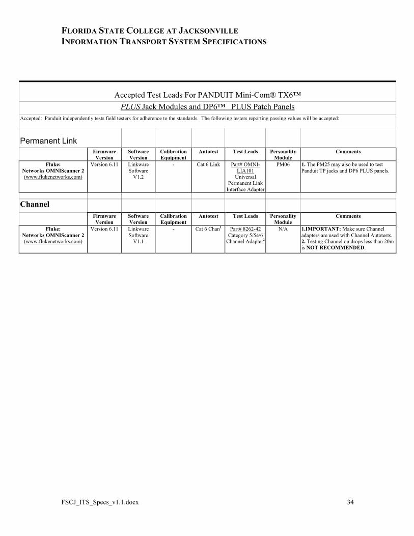
Accepted Test Leads For PANDUIT Mini-Com® TX6™ PLUS Jack Modules and DP6™ PLUS Patch Panels
Accepted: Panduit independently tests field testers for adherence to the standards. The following testers reporting passing values will be accepted:
Permanent Link
Firmware Version
Software Version
Calibration Equipment
Autotest Test Leads Personality Module
Comments
Fluke: Networks OMNIScanner 2 (www.flukenetworks.com)
Version 6.11 Linkware Software
V1.2
- Cat 6 Link Part# OMNI-LIA101
Universal Permanent Link
Interface Adapter
PM06 1. The PM25 may also be used to test Panduit TP jacks and DP6 PLUS panels.
Channel
Firmware Version
Software Version
Calibration Equipment
Autotest Test Leads Personality Module
Comments
Fluke: Networks OMNIScanner 2 (www.flukenetworks.com)
Version 6.11 Linkware Software
V1.1
- Cat 6 Chan1 Part# 8262-42 Category 5/5e/6
Channel Adapter2
N/A 1.IMPORTANT: Make sure Channel adapters are used with Channel Autotests. 2. Testing Channel on drops less than 20m is NOT RECOMMENDED.

FLORIDA STATE COLLEGE AT JACKSONVILLE INFORMATION TRANSPORT SYSTEM SPECIFICATIONS
FSCJ_ITS_Specs_v1.1.docx 35
9. Appendixes:
9.1. Appendix 7 Renamed Section 7 from Additional Documentation to Identification. Section Covers Patch Panel and Outlet Labeling