Embed Size (px)
Citation preview

Fluids, Thermodynamics, Waves, & OpticsOpticsLab 9
Interference and Diffraction
Lana Sheridan
De Anza College
Jun 13, 2018

Overview
• Purpose
• Theory• interference from two coherent light sources
• diffraction from a single light source
• interference and diffraction
• Part 1: Single slit diffraction
• Part 2: Two slit interference with diffraction

Purpose of the Lab
To investigate the wave nature of light.
You will use a laser on an optical bench and screens to studydiffraction and interference patterns.
You will
1 observe a single slit diffraction pattern and calculate the slitwidth from the observed pattern.
2 observe a two-slit pattern and calculate the slit separation andslit widths.

Equipment

Interference of Light
1136 Chapter 37 Wave Optics
the upper one by exactly one wavelength, they still arrive in phase at P and a sec-ond bright fringe appears at this location. At point R in Figure 37.3c, however, between points O and P, the lower wave has fallen half a wavelength behind the upper wave and a crest of the upper wave overlaps a trough of the lower wave, giv-ing rise to destructive interference at point R. A dark fringe is therefore observed at this location. If two lightbulbs are placed side by side so that light from both bulbs combines, no interference effects are observed because the light waves from one bulb are emitted independently of those from the other bulb. The emissions from the two lightbulbs do not maintain a constant phase relationship with each other over time. Light waves from an ordinary source such as a lightbulb undergo random phase changes in time intervals of less than a nanosecond. Therefore, the conditions for constructive interference, destructive interference, or some intermediate state are maintained only for such short time intervals. Because the eye cannot follow such rapid changes, no interference effects are observed. Such light sources are said to be incoherent. To observe interference of waves from two sources, the following conditions must be met:
The sources must be coherent; that is, they must maintain a constant phase with respect to each other.
The sources should be monochromatic; that is, they should be of a single wavelength.
As an example, single-frequency sound waves emitted by two side-by-side loud-speakers driven by a single amplifier can interfere with each other because the two speakers are coherent. In other words, they respond to the amplifier in the same way at the same time. A common method for producing two coherent light sources is to use a mono-chromatic source to illuminate a barrier containing two small openings, usually in the shape of slits, as in the case of Young’s experiment illustrated in Figure 37.1. The light emerging from the two slits is coherent because a single source produces the original light beam and the two slits serve only to separate the original beam into two parts (which, after all, is what is done to the sound signal from two side-by-side loudspeakers). Any random change in the light emitted by the source occurs in both beams at the same time. As a result, interference effects can be observed when the light from the two slits arrives at a viewing screen. If the light traveled only in its original direction after passing through the slits as shown in Figure 37.4a, the waves would not overlap and no interference pattern would be seen. Instead, as we have discussed in our treatment of Huygens’s prin-ciple (Section 35.6), the waves spread out from the slits as shown in Figure 37.4b. In other words, the light deviates from a straight-line path and enters the region that
Conditions for interference X
b
Constructive interference also occurs at point P.
Brightfringe
S1
S2
O
P
c
Destructive interference occurs at point R when the two waves combine because the lower wave falls one-half a wavelength behind the upper wave.
Darkfringe
P
R
O
S1
S2
a
Constructive interference occurs at point O when the waves combine.
Brightfringe
S1
S2
O
Viewing screen
Figure 37.3 Waves leave the slits and combine at various points on the viewing screen. (All figures not to scale.)
In places where the path lengths differ by a whole number ofwavelengths (mλ) there is constructive interference.
1Serway & Jewett.

Interference
A pattern of light and dark “fringes” (stripes of light and darkness)appear on the screen.
Zoomed in view:

Interference: Finding the Maxima
For a distant screen and closely placed slits, the two rays are nearlyparallel.
37.2 Analysis Model: Waves in Interference 1137
would otherwise be shadowed. As noted in Section 35.3, this divergence of light from its initial line of travel is called diffraction.
37.2 Analysis Model: Waves in InterferenceWe discussed the superposition principle for waves on strings in Section 18.1, lead-ing to a one-dimensional version of the waves in interference analysis model. In Example 18.1 on page 537, we briefly discussed a two-dimensional interference phenomenon for sound from two loudspeakers. In walking from point O to point P in Figure 18.5, the listener experienced a maximum in sound intensity at O and a minimum at P. This experience is exactly analogous to an observer looking at point O in Figure 37.3 and seeing a bright fringe and then sweeping his eyes upward to point R, where there is a minimum in light intensity. Let’s look in more detail at the two-dimensional nature of Young’s experiment with the help of Figure 37.5. The viewing screen is located a perpendicular distance L from the barrier containing two slits, S1 and S2 (Fig. 37.5a). These slits are separated by a distance d, and the source is monochromatic. To reach any arbitrary point P in the upper half of the screen, a wave from the lower slit must travel farther than a wave from the upper slit. The extra distance traveled from the lower slit is the path differ-ence d (Greek letter delta). If we assume the rays labeled r1 and r2 are parallel (Fig. 37.5b), which is approximately true if L is much greater than d, then d is given by
d 5 r2 2 r1 5 d sin u (37.1)
The value of d determines whether the two waves are in phase when they arrive at point P. If d is either zero or some integer multiple of the wavelength, the two waves
a b
When we assume r1 is parallel to r2, the path difference between the two rays is r2 ! r1 " d sin u.
d " r2 ! r1 " d sin u
S1
S2
d
r2
r1
d
S1
S2 d
Q
LViewing screen
P
O
y
r1
r2u u u
Figure 37.5 (a) Geometric construction for describing Young’s double-slit experiment (not to scale). (b) The slits are represented as sources, and the outgoing light rays are assumed to be parallel as they travel to P. To achieve that in practice, it is essen-tial that L .. d.
a
Light passing through narrow slits does not behave this way.
b
Light passing through narrow slits diffracts.
Figure 37.4 (a) If light waves did not spread out after passing through the slits, no interference would occur. (b) The light waves from the two slits overlap as they spread out, filling what we expect to be shadowed regions with light and producing interference fringes on a screen placed to the right of the slits.
Looking at the right triangle with hypotenuse d (the slit separationdistance): δ = d sin θ.

Interference: Finding the Angles of the Maxima
Maxima (bright fringes) occur when
d sin θmax = mi λ where mi ∈ Z
Minima (dark fringes) occur when
d sin θmin =
(mi +
1
2
)λ where mi ∈ Z
These expressions give us the angles (measured outward from theaxis that passes through the midpoint of the slits) where the brightand dark fringes occur.

Young’s Experiment: Finding the Position of theMaxima
We can also predict the distance from the center of the screen, y ,in terms of the distance from the slits to the screen, L.
37.2 Analysis Model: Waves in Interference 1137
would otherwise be shadowed. As noted in Section 35.3, this divergence of light from its initial line of travel is called diffraction.
37.2 Analysis Model: Waves in InterferenceWe discussed the superposition principle for waves on strings in Section 18.1, lead-ing to a one-dimensional version of the waves in interference analysis model. In Example 18.1 on page 537, we briefly discussed a two-dimensional interference phenomenon for sound from two loudspeakers. In walking from point O to point P in Figure 18.5, the listener experienced a maximum in sound intensity at O and a minimum at P. This experience is exactly analogous to an observer looking at point O in Figure 37.3 and seeing a bright fringe and then sweeping his eyes upward to point R, where there is a minimum in light intensity. Let’s look in more detail at the two-dimensional nature of Young’s experiment with the help of Figure 37.5. The viewing screen is located a perpendicular distance L from the barrier containing two slits, S1 and S2 (Fig. 37.5a). These slits are separated by a distance d, and the source is monochromatic. To reach any arbitrary point P in the upper half of the screen, a wave from the lower slit must travel farther than a wave from the upper slit. The extra distance traveled from the lower slit is the path differ-ence d (Greek letter delta). If we assume the rays labeled r1 and r2 are parallel (Fig. 37.5b), which is approximately true if L is much greater than d, then d is given by
d 5 r2 2 r1 5 d sin u (37.1)
The value of d determines whether the two waves are in phase when they arrive at point P. If d is either zero or some integer multiple of the wavelength, the two waves
a b
When we assume r1 is parallel to r2, the path difference between the two rays is r2 ! r1 " d sin u.
d " r2 ! r1 " d sin u
S1
S2
d
r2
r1
d
S1
S2 d
Q
LViewing screen
P
O
y
r1
r2u u u
Figure 37.5 (a) Geometric construction for describing Young’s double-slit experiment (not to scale). (b) The slits are represented as sources, and the outgoing light rays are assumed to be parallel as they travel to P. To achieve that in practice, it is essen-tial that L .. d.
a
Light passing through narrow slits does not behave this way.
b
Light passing through narrow slits diffracts.
Figure 37.4 (a) If light waves did not spread out after passing through the slits, no interference would occur. (b) The light waves from the two slits overlap as they spread out, filling what we expect to be shadowed regions with light and producing interference fringes on a screen placed to the right of the slits.
tan θ =y
L≈ sin θ if θ is small

Interference: Finding the Angles of the Maxima
Maxima (bright fringes) occur when y is such that:
d =mi λ L
ywhere mi ∈ Z
Minima (dark fringes) occur when y is such that:
d =
(mi +
12
)λ L
ywhere mi ∈ Z
These expressions give us the angles (measured outward from theaxis that passes through the midpoint of the slits) where the brightand dark fringes occur.

Diffraction: Intensity Pattern from a Single Slit
1162 Chapter 38 Diffraction Patterns and Polarization
a Fraunhofer diffraction pattern. A bright fringe is observed along the axis at u 5 0, with alternating dark and bright fringes on each side of the central bright fringe. Until now, we have assumed slits are point sources of light. In this section, we abandon that assumption and see how the finite width of slits is the basis for under-standing Fraunhofer diffraction. We can explain some important features of this phenomenon by examining waves coming from various portions of the slit as shown in Figure 38.5. According to Huygens’s principle, each portion of the slit acts as a source of light waves. Hence, light from one portion of the slit can interfere with light from another portion, and the resultant light intensity on a viewing screen depends on the direction u. Based on this analysis, we recognize that a diffraction pattern is actually an interference pattern in which the different sources of light are different portions of the single slit! Therefore, the diffraction patterns we discuss in this chapter are applications of the waves in interference analysis model. To analyze the diffraction pattern, let’s divide the slit into two halves as shown in Figure 38.5. Keeping in mind that all the waves are in phase as they leave the slit, consider rays 1 and 3. As these two rays travel toward a viewing screen far to the right of the figure, ray 1 travels farther than ray 3 by an amount equal to the path difference (a/2) sin u, where a is the width of the slit. Similarly, the path difference between rays 2 and 4 is also (a/2) sin u, as is that between rays 3 and 5. If this path difference is exactly half a wavelength (corresponding to a phase difference of 180°), the pairs of waves cancel each other and destructive interference results. This cancel-lation occurs for any two rays that originate at points separated by half the slit width because the phase difference between two such points is 180°. Therefore, waves from the upper half of the slit interfere destructively with waves from the lower half when
a2
sin u 5l
2
or, if we consider waves at angle u both above the dashed line in Figure 38.5 and below,
sin u 5 6l
a
Dividing the slit into four equal parts and using similar reasoning, we find that the viewing screen is also dark when
sin u 5 62 l
a
Likewise, dividing the slit into six equal parts shows that darkness occurs on the screen when
sin u 5 63 l
a
Pitfall Prevention 38.1Diffraction Versus Diffraction Pattern Diffraction refers to the general behavior of waves spread-ing out as they pass through a slit. We used diffraction in explaining the existence of an interference pattern in Chapter 37. A diffraction pattern is actually a misnomer, but is deeply entrenched in the lan-guage of physics. The diffraction pattern seen on a screen when a single slit is illuminated is actually another interference pattern. The interference is between parts of the incident light illuminating dif-ferent regions of the slit.
Figure 38.4 (a) Geometry for analyzing the Fraunhofer diffrac-tion pattern of a single slit. (Draw-ing not to scale.) (b) Simulation of a single-slit Fraunhofer diffrac-tion pattern.
Slit
min
min
min
min
max
max
max
Incomingwave Viewing screen
u
The pattern consists of a central bright fringe flanked by much weaker maxima alternating with dark fringes.
a b
L
Each portion of the slit acts as a point source of light waves.
a
a/2
a/2
2
3
2
5
4
1
u
The path difference between rays 1 and 3, rays 2 and 4, or rays 3 and 5 is (a/ 2) sin u.
sin ua
Figure 38.5 Paths of light rays that encounter a narrow slit of width a and diffract toward a screen in the direction described by angle u (not to scale).

Diffraction: Understanding the Single Slit PatternConsider a series of point sources in different parts of the slit. Theslit has width a.
1162 Chapter 38 Diffraction Patterns and Polarization
a Fraunhofer diffraction pattern. A bright fringe is observed along the axis at u 5 0, with alternating dark and bright fringes on each side of the central bright fringe. Until now, we have assumed slits are point sources of light. In this section, we abandon that assumption and see how the finite width of slits is the basis for under-standing Fraunhofer diffraction. We can explain some important features of this phenomenon by examining waves coming from various portions of the slit as shown in Figure 38.5. According to Huygens’s principle, each portion of the slit acts as a source of light waves. Hence, light from one portion of the slit can interfere with light from another portion, and the resultant light intensity on a viewing screen depends on the direction u. Based on this analysis, we recognize that a diffraction pattern is actually an interference pattern in which the different sources of light are different portions of the single slit! Therefore, the diffraction patterns we discuss in this chapter are applications of the waves in interference analysis model. To analyze the diffraction pattern, let’s divide the slit into two halves as shown in Figure 38.5. Keeping in mind that all the waves are in phase as they leave the slit, consider rays 1 and 3. As these two rays travel toward a viewing screen far to the right of the figure, ray 1 travels farther than ray 3 by an amount equal to the path difference (a/2) sin u, where a is the width of the slit. Similarly, the path difference between rays 2 and 4 is also (a/2) sin u, as is that between rays 3 and 5. If this path difference is exactly half a wavelength (corresponding to a phase difference of 180°), the pairs of waves cancel each other and destructive interference results. This cancel-lation occurs for any two rays that originate at points separated by half the slit width because the phase difference between two such points is 180°. Therefore, waves from the upper half of the slit interfere destructively with waves from the lower half when
a2
sin u 5l
2
or, if we consider waves at angle u both above the dashed line in Figure 38.5 and below,
sin u 5 6l
a
Dividing the slit into four equal parts and using similar reasoning, we find that the viewing screen is also dark when
sin u 5 62 l
a
Likewise, dividing the slit into six equal parts shows that darkness occurs on the screen when
sin u 5 63 l
a
Pitfall Prevention 38.1Diffraction Versus Diffraction Pattern Diffraction refers to the general behavior of waves spread-ing out as they pass through a slit. We used diffraction in explaining the existence of an interference pattern in Chapter 37. A diffraction pattern is actually a misnomer, but is deeply entrenched in the lan-guage of physics. The diffraction pattern seen on a screen when a single slit is illuminated is actually another interference pattern. The interference is between parts of the incident light illuminating dif-ferent regions of the slit.
Figure 38.4 (a) Geometry for analyzing the Fraunhofer diffrac-tion pattern of a single slit. (Draw-ing not to scale.) (b) Simulation of a single-slit Fraunhofer diffrac-tion pattern.
Slit
min
min
min
min
max
max
max
Incomingwave Viewing screen
u
The pattern consists of a central bright fringe flanked by much weaker maxima alternating with dark fringes.
a b
L
Each portion of the slit acts as a point source of light waves.
a
a/2
a/2
2
3
2
5
4
1
u
The path difference between rays 1 and 3, rays 2 and 4, or rays 3 and 5 is (a/ 2) sin u.
sin ua
Figure 38.5 Paths of light rays that encounter a narrow slit of width a and diffract toward a screen in the direction described by angle u (not to scale).

Diffraction: Understanding the Single Slit Pattern
We can find minima (dark fringes) in the pattern by breaking upour point sources into pairs that cancel each other out.
Matching point sources in the top half of the slit with ones in thebottom half, the source separation distances will be d = a/2.
This will be a fringe dark when:
δ =a
2sin θ =
λ
2

Diffraction: Understanding the Single Slit Pattern
However, we could also break the slit up into 4 equal parts andmatch sources from the 1st and 2nd, and match from the 3rd and4th.
This will be dark when:
δ =a
4sin θ =
λ
2
If we break the slit up into 6 equal parts and match sources fromthe 1st and 2nd, the 3rd and 4th, and the 5th and 6th.
This will be dark when:
δ =a
6sin θ =
λ
2

Diffraction Minima
In general we expect dark fringes when:
sin θmin = mdλ
a
or, equivalently,
a sin θmin = md λ where md = ±1,±2,±3, ...

Interference AND Diffraction: Two slits that havesome width
Suppose two slits each have width a and their centers are adistance d apart.
What intensity pattern do they create?

Interference AND Diffraction: Two slits that havesome width
38.2 Diffraction Patterns from Narrow Slits 1165
blue curve in Figure 38.7 represents the factor in square brackets in Equation 38.3. The cosine-squared factor by itself would give a series of peaks all with the same height as the highest peak of the red-brown curve in Figure 38.7. Because of the effect of the square-bracket factor, however, these peaks vary in height as shown. Equation 37.2 indicates the conditions for interference maxima as d sin u 5 ml, where d is the distance between the two slits. Equation 38.1 specifies that the first diffraction minimum occurs when a sin u 5 l, where a is the slit width. Dividing Equation 37.2 by Equation 38.1 (with m 5 1) allows us to determine which interfer-ence maximum coincides with the first diffraction minimum:
d sin ua sin u
5ml
l
da 5 m (38.4)
In Figure 38.7, d/a 5 18 mm/3.0 mm 5 6. Therefore, the sixth interference maxi-mum (if we count the central maximum as m 5 0) is aligned with the first diffrac-tion minimum and is dark.
Q uick Quiz 38.2 Consider the central peak in the diffraction envelope in Figure 38.7 and look closely at the horizontal scale. Suppose the wavelength of the light is changed to 450 nm. What happens to this central peak? (a) The width of the peak decreases, and the number of interference fringes it encloses decreases. (b) The width of the peak decreases, and the number of interference fringes it encloses increases. (c) The width of the peak decreases, and the number of interference fringes it encloses remains the same. (d) The width of the peak increases, and the number of interference fringes it encloses decreases. (e) The width of the peak increases, and the number of interference fringes it encloses increases. (f) The width of the peak increases, and the number of interference fringes it encloses remains the same. (g) The width of the peak remains the same, and the number of interference fringes it encloses decreases. (h) The width of the peak remains the same, and the number of interference fringes it encloses increases. (i) The width of the peak remains the same, and the number of interference fringes it encloses remains the same.
!3p !2p 2p 3p!p p
The diffraction pattern acts as an “envelope” (the blue dashed curve) that controls the intensity of the regularly spaced interference maxima.
I
Diffractionminima
Interferencefringes
a sin ulp
Figure 38.7 The combined effects of two-slit and single-slit interference. This pattern is pro-duced when 650-nm light waves pass through two 3.0-mm slits that are 18 mm apart.
In thepicture,d/a = 6
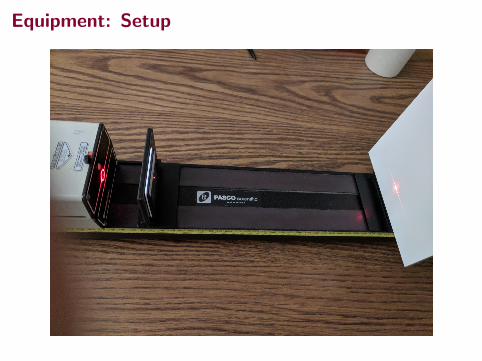
Equipment: Setup

Diffraction Pattern Measurement
Figure: For demonstration only! Measure the distances from the patterncopied into your lab book, so that you do not accidentally scatter thelaser off of the calipers and into your eyes.

Interference and Diffraction Pattern


![P µ î t ^ µ o Ç ] o t } l · 3q 4c 4c 4c4 4c 4c4 4c 4c 4c44c q3 4c 4c4 4c 4c 4c 4!(!(!(!(!(!(!(!(!(!(!!(!!!!!(!(!(!(!(!(!!(!(!(wps26 wps19 wps10 wps24 wps23 wps25 wps01 wps20](https://img.pdfslide.net/doc/110x75/5f69b696a9d73730bd76a7d7/p-t-o-o-t-l-3q-4c-4c-4c4-4c-4c4-4c-4c-4c44c-q3-4c-4c4-4c-4c-4c.jpg)