Embed Size (px)
Citation preview
Part #20280
FLUX CORE 90
WELDER ASSEMBLY & OPERATING
INSTRUCTIONS

3 Eastwood Technical Assistance: 800.544.5118 >> [email protected]
STATEMENT OF LIMITED WARRANTY The Eastwood Company (hereinafter “Eastwood”) warrants to the end user (purchaser) of all new welding and cutting equipment
(collectively called the “products”) that it will be free of defects in workmanship and material. This warranty is void if the equipment has been subjected to improper installation, improper care or abnormal operations.
WARRANTY PERIOD: All warranty periods begin on the date of purchase from Eastwood. Warranty Periods are listed below, along with the products
covered during those warranty periods:
1 Year Warranty on Material, Workmanship, and Defects: • Eastwood Flux Core 90 Welder
Items not covered under this warranty: Contact tips, nozzles, wire, and ground clamp and cable. All other components are covered by the warranty and will be repaired or replaced at the discretion of Eastwood.
CONDITIONS OF WARRANTY TO OBTAIN WARRANTY COVERAGE: Purchaser must first contact Eastwood at 1-800-345-1178 for an RMA# before Eastwood will
accept any welder returns. Final determination of warranty on welding and cutting equipment
will be made by Eastwood.
WARRANTY REPAIR: If Eastwood confirms the existence of a defect covered under this warranty plan, Eastwood will determine whether repair or
replacement is the most suitable option to rectify the defect. At Eastwood’s request, the purchaser must return, to Eastwood, any products claimed defective under Eastwood’s warranty.
FREIGHT COSTS: The purchaser is responsible for shipment to and from Eastwood.
WARRANTY LIMITATIONS: EASTWOOD WILL NOT ACCEPT RESPONSIBILITY OR LIABILITY FOR REPAIRS UNLESS MADE BY EASTWOOD.
EASTWOOD’S LIABILITY UNDER THIS WARRANTY SHALL NOT EXCEED THE COST OF CORRECTING THE DEFECT OF THE EASTWOOD PRODUCT. EASTWOOD WILL NOT BE LIABLE
FOR INCIDENTAL OR CONSEQUENTIAL DAMAGES (SUCH AS LOSS OF BUSINESS, ETC.) CAUSED BY THE DEFECT OR THE TIME INVOLVED TO CORRECT THE DEFECT. THIS
WRITTEN WARRANTY IS THE ONLY EXPRESS WARRANTY PROVIDED BY EASTWOOD WITH RESPECT TO ITS PRODUCTS. WARRANTIES IMPLIED BY LAW SUCH AS THE WARRANTY OF MERCHANTABILITY ARE LIMITED TO THE
DURATION OF THIS LIMITED WARRANTY FOR THE EQUIPMENT INVOLVED. THIS WARRANTY GIVES THE PURCHASER SPECIFIC LEGAL RIGHTS.
THE PURCHASER MAY ALSO HAVE OTHER RIGHTS WHICH VARY FROM STATE TO STATE.
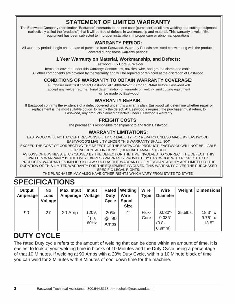
SPECIFICATIONS Output
Amperage No
Load
Voltage
Max. Input Amperage
Input
Voltage Rated
Duty
Cycle
Welding Wire
Spool Size
Wire
Type Wire
Diameter Weight Dimensions
90 27 20 Amp 120V,
1ph,
60Hz
20%
@ 90
Amps
4" Flux-
Core 0.030"- 0.035”
(0.8-
0.9mm)
35.5lbs. 18.3" x
9.75" x
13.8"
DUTY CYCLE The rated Duty cycle refers to the amount of welding that can be done within an amount of time. It is
easiest to look at your welding time in blocks of 10 Minutes and the Duty Cycle being a percentage
of that 10 Minutes. If welding at 90 Amps with a 20% Duty Cycle, within a 10 Minute block of time
you can weld for 2 Minutes with 8 Minutes of cool down time for the machine.
To order parts and supplies: 800.345.1178 >> eastwood.com 4
SAFETY INFORMATION
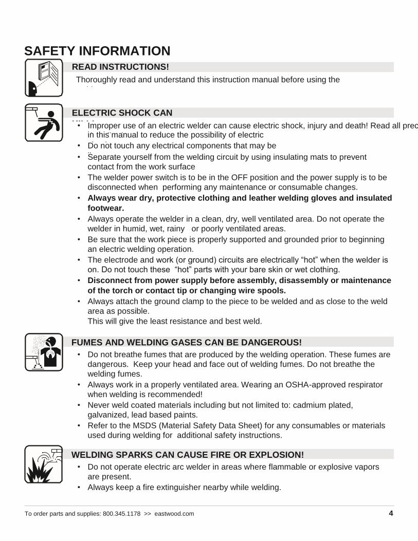
• Separate yourself from the welding circuit by using insulating mats to prevent
contact from the work surface
• The welder power switch is to be in the OFF position and the power supply is to be
disconnected when performing any maintenance or consumable changes.
• Always wear dry, protective clothing and leather welding gloves and insulated
footwear.
• Always operate the welder in a clean, dry, well ventilated area. Do not operate the
welder in humid, wet, rainy or poorly ventilated areas.
• Be sure that the work piece is properly supported and grounded prior to beginning
an electric welding operation.
• The electrode and work (or ground) circuits are electrically “hot” when the welder is
on. Do not touch these “hot” parts with your bare skin or wet clothing.
• Disconnect from power supply before assembly, disassembly or maintenance
of the torch or contact tip or changing wire spools.
• Always attach the ground clamp to the piece to be welded and as close to the weld
area as possible.
This will give the least resistance and best weld.
FUMES AND WELDING GASES CAN BE DANGEROUS!
• Do not breathe fumes that are produced by the welding operation. These fumes are
dangerous. Keep your head and face out of welding fumes. Do not breathe the
welding fumes.
• Always work in a properly ventilated area. Wearing an OSHA-approved respirator
when welding is recommended!
• Never weld coated materials including but not limited to: cadmium plated,
galvanized, lead based paints.
• Refer to the MSDS (Material Safety Data Sheet) for any consumables or materials
used during welding for additional safety instructions.
WELDING SPARKS CAN CAUSE FIRE OR EXPLOSION!
• Do not operate electric arc welder in areas where flammable or explosive vapors
are present.
• Always keep a fire extinguisher nearby while welding.
READ INSTRUCTIONS!
Thoroughly read and understand this instruction manual before using the
welder.
ELECTRIC SHOCK CAN
KILL! • Improper use of an electric welder can cause electric shock, injury and death! Read all precautions
described
in this manual to reduce the possibility of electric
shock. • Do not touch any electrical components that may be
live.

To order parts and supplies: 800.345.1178 >> eastwood.com 5
• Use welding blankets to protect painted surfaces, dash boards, engines, etc.
• Ensure power supply has properly rated wiring to handle power usage.
• Do not use on or near combustible surfaces.
• Remove all flammable items within 35 feet of the welding area.
• Do not weld frozen pipes.

6 Eastwood Technical Assistance: 800.544.5118 >> [email protected]
SAFETY INFORMATION
ARC RAYS CAN BURN!
• Use a shield with the proper filter (a minimum of #11) to protect your eyes from
sparks and the rays of the arc when welding or when observing open arc welding.
(see ANSI Z49.1 and Z87.1 for safety standards).
• Use suitable clothing made from durable flame-resistant material to protect your
skin. Protect nearby individuals with a non-flammable barrier.
• Wear safety glasses under your welding helmet with side shields.
• If other persons are in the area of welding use welding screens to protect
bystanders from sparks and arc rays.
HOT METAL WILL BURN!
• Electric welding operations cause sparks and heat metal to temperatures that will
cause severe burns!
• Use protective gloves and clothing when performing any welding operations. Always
wear long pants, long-sleeved shirts and leather welding gloves.
• Make sure that all persons in the welding area are protected from heat, sparks and
ultraviolet rays. Use additional face shields and flame resistant barriers as needed.
• Never touch work piece until it has completely cooled.
ELECTROMAGNETIC FIELDS MAY BE DANGEROUS!
• The electromagnetic field that is generated during arc welding may interfere with
various electrical and electronic devices such as cardiac pacemakers. Anyone using
such devices should consult with their physician prior to performing any electric
welding operations.
• Exposure to electromagnetic fields while welding may have other health effects
which are not known.
WELDING WIRE CAN BE DANGEROUS!
• Never point the welding gun at any part of the body, other people, or metal
surfaces.
• Wear safety glasses and handle welding wire safety as it can be sharp and cause
injury.
MOVING PARTS CAN BE DANGEROUS!
• Use care when working near the drive motor assembly as it can pinch.
• Do not put fingers or other body parts between moving parts.
FLYING METAL CHIPS CAN CAUSE INJURY!
• Welding, brushing, hammering, chipping, and grinding can cause flying metal chips
and sparks.
7 Eastwood Technical Assistance: 800.544.5118 >> [email protected]
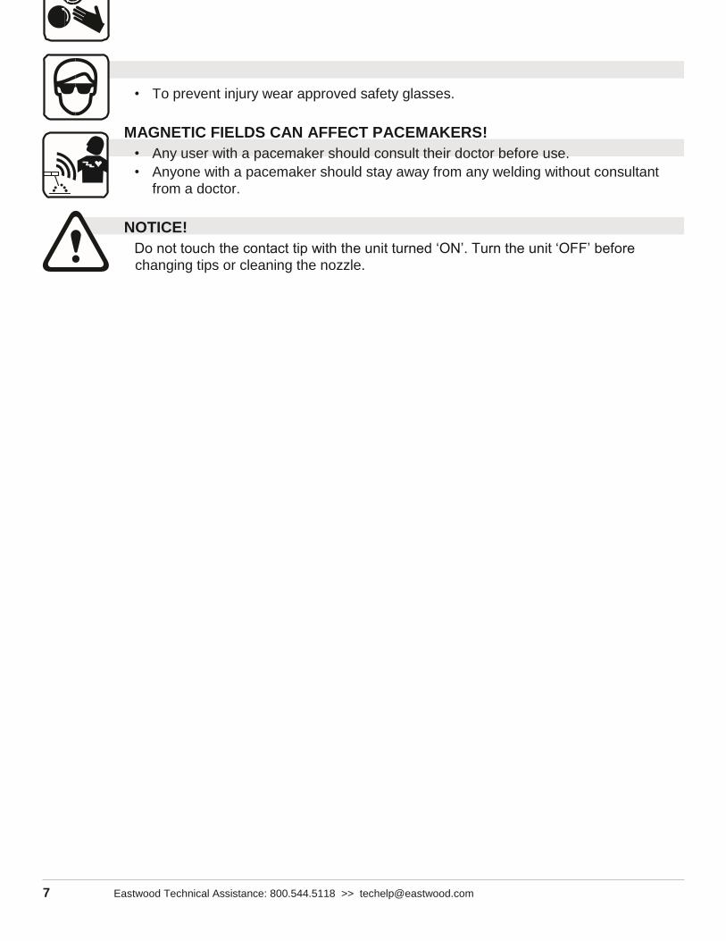
• To prevent injury wear approved safety glasses.
MAGNETIC FIELDS CAN AFFECT PACEMAKERS!
• Any user with a pacemaker should consult their doctor before use.
• Anyone with a pacemaker should stay away from any welding without consultant
from a doctor.
NOTICE!
Do not touch the contact tip with the unit turned ‘ON’. Turn the unit ‘OFF’ before
changing tips or cleaning the nozzle.

To order parts and supplies: 800.345.1178 >> eastwood.com 8
UNPACKING When unpacking your Eastwood Flux Core 90, check to make sure all of the parts listed below
are included:
• Flux Core 90 Welder with Welding Gun and Ground Cable
• Chipping Hammer / Wire Brush
To order parts and supplies: 800.345.1178 >> eastwood.com 9
• 1 lb. Spool of 0.030" (0.8mm) Flux-Core
Wire • Spare Contact
Tip
1
• Instruction
Manual
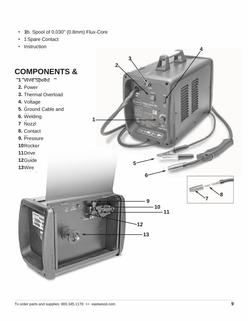
COMPONENTS &
CONTROLS 1
.
Wire Speed
Control 2. Power
Switch 3. Thermal Overload
Indicator 4. Voltage
Control 5. Ground Cable and
Clamp 6. Welding
Gun 7
.
Nozzl
e 8. Contact
Tip 9. Pressure
Adjuster 10
.
Rocker
Arm 11
.
Drive
Roller 12
.
Guide
Pipe 13
.
Wire
Spindle
2
3
4
1
5
6
7 8
9
10 11
12
13

10 Eastwood Technical Assistance: 800.544.5118 >> [email protected]
ASSEMBLY INSTALLING THE HANDLE
1. Line up the holes in the handle with the holes
in the top in the welder.
2. On each screw place an included lock
washer followed by a flat washer.
3. Insert each screw through the handle and
into the top of the welder and tighten.
CONNECTING THE WELDER TO A POWER
SOURCE
The Eastwood Flux Core 90 welder requires a
dedicated 120 VAC, 20 Amp, 60 Hz grounded
outlet protected by a circuit breaker. Do not use
on power sources that have voltages less than
105 VAC or higher than 132 VAC. If using an
extension cord, use a minimum 12 AWG cord for
up to 25 feet.
CHANGING THE DRIVE ROLLER
The Eastwood Flux Core 90 comes set up and
ready to use 0.030" (0.8mm) Flux-Core Wire. If
0.035" (0.9mm) wire is to be used, the drive roller
needs to be adjusted. Adjust the drive roller
according to the following procedure:
1. Open the top door of the welder to access the
drive motor compartment.
2. Lift the Pressure Adjuster (FIG. B-B1) out of
the way and move the Rocker Arm (FIG. B-
B2) away from the drive roller.
3. Remove the Drive Roller Thumb Screw (FIG.
B-B3) by turning it counter clockwise and
pulling it away from the roller.
4. Remove the Drive Roller and view the wire sizes stamped on each side of the roller.
5. Install the Drive Roller in the orientation so that the size of the wire you are using is facing
you on the side of the drive roller.
6. Reinstall the Drive Roller Thumb Screw (FIG. B-B3).
7. Put the Rocker Arm (FIG. B-B2) back in place and reset the Pressure Adjuster (FIG. B-
B1).
FI
G . A
B1
FI
G . B
B2
B3

To order parts and supplies: 800.345.1178 >> eastwood.com 11
The Eastwood Flux Core 90 can be used with a 4 inch wire spool only. To install the wire spool
follow the procedure listed below:
1. Open the door of the welder and remove the wing nut (FIG. C-C1) and spacer from the
Wire Spool Spindle.
2. Slide the 4 inch Wire Spool onto the Wire Spindle and reinstall the spacer and wing nut.
INSTALLING THE WIRE
SPOOL
FI
G . C
C1
C2
C3
C4
12 Eastwood Technical Assistance: 800.544.5118 >> [email protected]
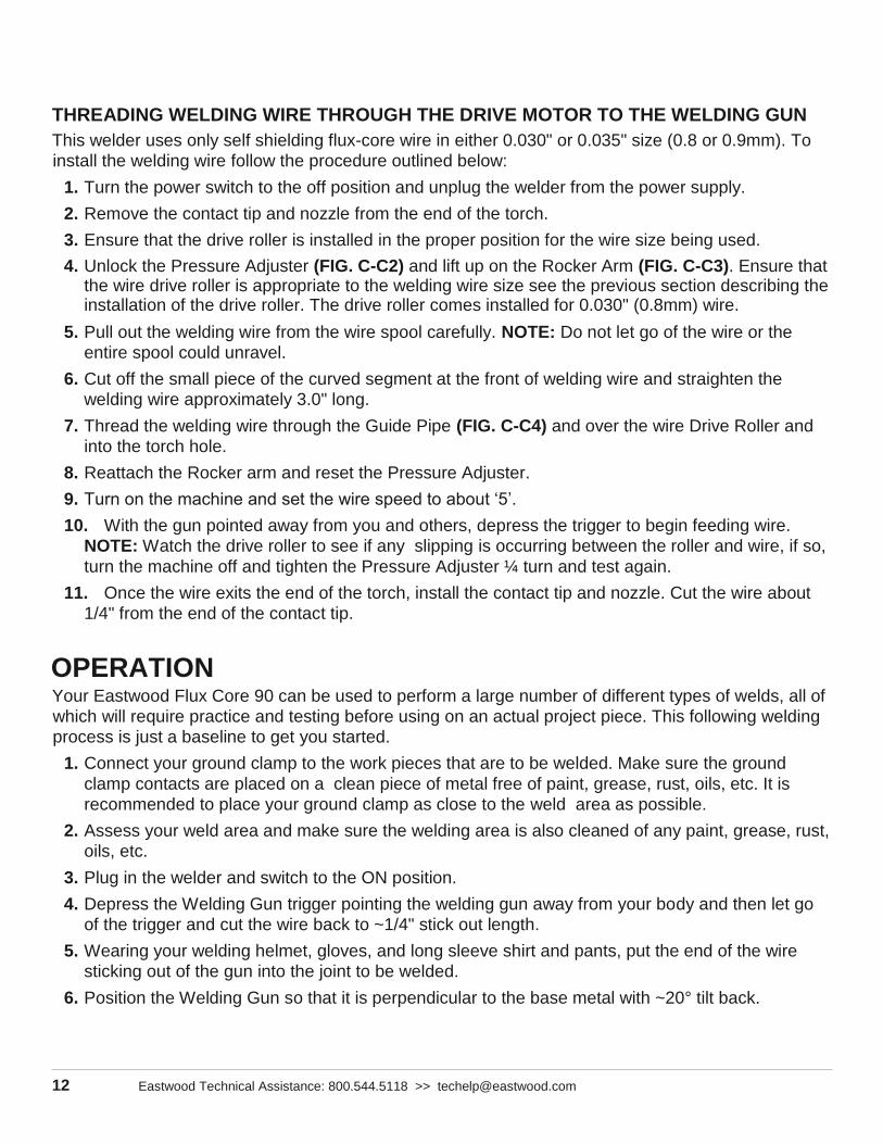
THREADING WELDING WIRE THROUGH THE DRIVE MOTOR TO THE WELDING GUN
This welder uses only self shielding flux-core wire in either 0.030" or 0.035" size (0.8 or 0.9mm). To
install the welding wire follow the procedure outlined below:
1. Turn the power switch to the off position and unplug the welder from the power supply.
2. Remove the contact tip and nozzle from the end of the torch.
3. Ensure that the drive roller is installed in the proper position for the wire size being used.
4. Unlock the Pressure Adjuster (FIG. C-C2) and lift up on the Rocker Arm (FIG. C-C3). Ensure that the wire drive roller is appropriate to the welding wire size see the previous section describing the installation of the drive roller. The drive roller comes installed for 0.030" (0.8mm) wire.
5. Pull out the welding wire from the wire spool carefully. NOTE: Do not let go of the wire or the
entire spool could unravel.
6. Cut off the small piece of the curved segment at the front of welding wire and straighten the
welding wire approximately 3.0" long.
7. Thread the welding wire through the Guide Pipe (FIG. C-C4) and over the wire Drive Roller and
into the torch hole.
8. Reattach the Rocker arm and reset the Pressure Adjuster.
9. Turn on the machine and set the wire speed to about ‘5’.
10. With the gun pointed away from you and others, depress the trigger to begin feeding wire.
NOTE: Watch the drive roller to see if any slipping is occurring between the roller and wire, if so,
turn the machine off and tighten the Pressure Adjuster ¼ turn and test again.
11. Once the wire exits the end of the torch, install the contact tip and nozzle. Cut the wire about
1/4" from the end of the contact tip.
OPERATION Your Eastwood Flux Core 90 can be used to perform a large number of different types of welds, all of
which will require practice and testing before using on an actual project piece. This following welding
process is just a baseline to get you started.
1. Connect your ground clamp to the work pieces that are to be welded. Make sure the ground
clamp contacts are placed on a clean piece of metal free of paint, grease, rust, oils, etc. It is
recommended to place your ground clamp as close to the weld area as possible.
2. Assess your weld area and make sure the welding area is also cleaned of any paint, grease, rust,
oils, etc.
3. Plug in the welder and switch to the ON position.
4. Depress the Welding Gun trigger pointing the welding gun away from your body and then let go
of the trigger and cut the wire back to ~1/4" stick out length.
5. Wearing your welding helmet, gloves, and long sleeve shirt and pants, put the end of the wire
sticking out of the gun into the joint to be welded.
6. Position the Welding Gun so that it is perpendicular to the base metal with ~20° tilt back.

13 Eastwood Technical Assistance: 800.544.5118 >> [email protected]
7. Depress the trigger to start the wire feed which starts the arc. NOTE: A push, perpendicular, or
drag technique can be used to weld the pieces together.
8. Once you depress the trigger and the arc has started, you will notice a molten puddle will form;
this puddle is the weld bead and will follow the motion of the Welding Gun. Watching the size of
the puddle dictates how fast you should be moving with the torch. If you burn through the
material you are either moving to slow or you need to set the machine to “LOW” voltage. If you’re
not penetrating the base metal you’re either moving too fast or you need to set the machine to
“HIGH” voltage.
9. Release the trigger on the Welding Gun to stop the weld.
10. After finished welding, turn off the welder.
To order parts and supplies: 800.345.1178 >> eastwood.com 14
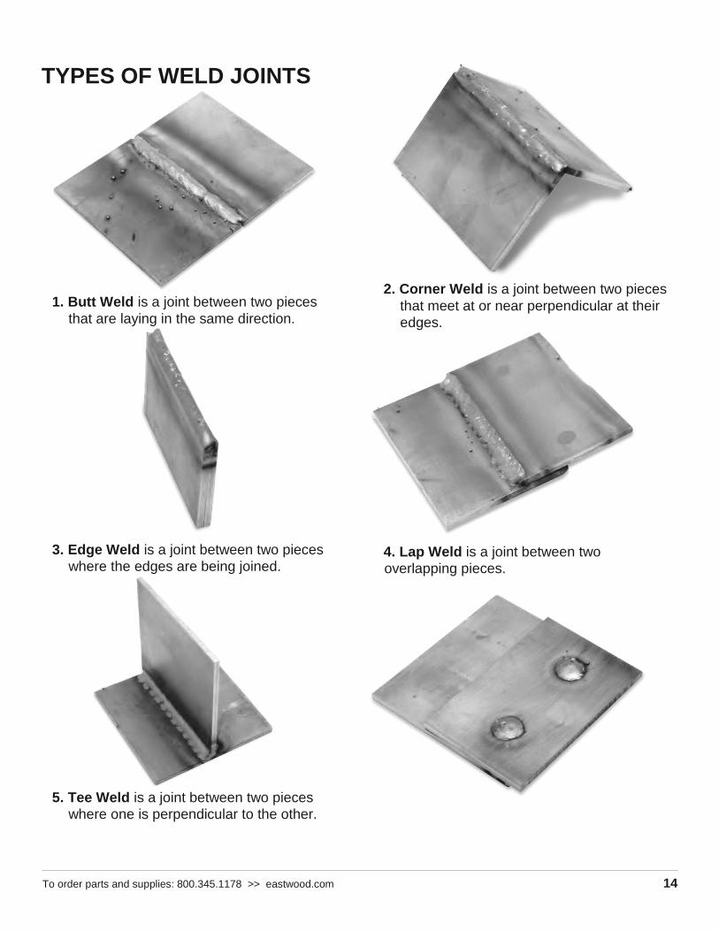
TYPES OF WELD JOINTS
1. Butt Weld is a joint between two pieces
that are laying in the same direction.
3. Edge Weld is a joint between two pieces
where the edges are being joined.
5. Tee Weld is a joint between two pieces
where one is perpendicular to the other.
2. Corner Weld is a joint between two pieces
that meet at or near perpendicular at their
edges.
4. Lap Weld is a joint between two
overlapping pieces.

To order parts and supplies: 800.345.1178 >> eastwood.com 15
6. Plug Weld is a joint which joins two
overlapping pieces by filling in a hole
punched in the top piece.
16 Eastwood Technical Assistance: 800.544.5118 >> [email protected]
Sheet Metal Welding Techniques
When welding sheet metal, a different approach is taken to account for how thin the metal is and it’s
susceptible to warping it is. The technique most often used is called Stitch Welding and this process
is described below:
1. Clean the metal to be welded of any paint, rust, oil, grease, dirt or any other contaminants that
may be on the surface of the piece.
2. Secure the pieces to be welded in place using clamps.
3. Set the machine to ‘LOW’ voltage and Wire Speed to ‘4’.
4. Get some pieces of scrap metal of the same thickness and verify that the settings will work for the
specific weld you will be making.
5. Once the settings have been fine tuned tack weld your final pieces in places and remove the
clamps if they are in the way of the weld.
6. The Stitch Welding technique can now be utilized which is basically a series of tacks connecting
together. To perform the technique, trigger the gun to form a tack weld and then continue to
trigger the gun, making a series of connected tack welds following along the path of the weld
joint. It is essential to keep moving around to spread out the heat making sure not to get one
section too hot and warp the metal.
7. Once the entire weld has been completed allow the metal to cool. If necessary follow up with a
flap disc to grind the weld bead flush.
Heavy Gauge Metal Welding Techniques
When welding heavy gauge metal, a different approach is usually taken to account
for the metal thickness. This approach is described below:
1. Clean the metal to be welded of any paint, rust, oil, grease, dirt or any other contaminants that
may be on the surface of the piece.
2. Secure the pieces to be welded in place using clamps. Be sure to leave a small gap between the
two pieces of metal for the weld to flow into, this will result in a lower bead height which will
require minimal finishing.
3. Set the machine to ‘HIGH’ voltage and Wire Speed to ‘7’.
4. Get some pieces of scrap metal of the same thickness and verify that the settings will work for the
specific weld you will be making.
5. Once the settings have been fine-tuned, tack weld your final pieces in places and remove the
clamps if they are in the way.
6. When welding heavy gauge metal there are two basic approaches to creating the weld. The first
is a continuous bead with steady gun movement along the length of the joint. The second type of
weld is a Stringer or Weave bead. This is accomplished by moving the torch in a circular or zig
zag pattern. Either of these techniques will create strong welds but in some cases the Stringer or
Weave type will create a more aesthetically appeasing weld bead.
7. Once the entire weld has been completed, allow the metal to cool. If necessary, follow up with a
flap disc to grind the weld bead flush.

17 Eastwood Technical Assistance: 800.544.5118 >> [email protected]

To order parts and supplies: 800.345.1178 >> eastwood.com 18
OVERLOAD PROTECTION Your Eastwood Flux Core 90 Welder is equipped with an overload breaker – this device will
protect your welder if the duty cycle is exceeded. If the output is exceeded, the internal breaker
will trip and stop power supply to the drive motor although the fan will still run to cool the unit. If
the breaker tripped resulting from an overload, the circuit breaker button under the side door of the
welder will extend out. This circuit breaker must be reset manually. Before resetting the circuit breaker button allow the welder to cool for a minimum of 15 minutes.
TROUBLESHOOTING Problem Cause Fix
Burn
Through
High voltage Adjust Voltage Output to low setting.
Fast wire speed Adjust Wire Speed to slower setting.
Slow Gun travel Increase your travel speed with the Welding Gun.
Lack of
Penetration
Low Voltage Adjust Voltage Output to high setting.
Slow Wire
Speed
Adjust Wire Speed to higher setting.
Fast Gun
Travel
Decrease your travel speed with the Welding Gun.
Excessive Wire
Stick Out
Move the Contact Tip on the Welding Gun closer to the work piece
to shorten the length of exposed Welding Wire.
Material Too
Thick
The Flux Core 90 is rated for a max. thickness of 1/8"; exceeding
this will result in poor penetration.
Poor Material
Prep
If welding heavy gauge metals, it may be necessary to increase the
welding gap between the two pieces and also bevel the edges on
the weld side of the pieces.
Excessive
Penetration
High Voltage Adjust Voltage Output to low setting.
Fast Wire
Speed
Adjust Wire Speed to slower setting.
Slow Gun
Travel
Increase your travel speed with the Welding Gun.
Warping
Lack of Tack
Welds
Tack weld the pieces in multiple areas to keep the pieces from
pulling apart.
No Clamping Use Welding Clamps to secure the pieces in their proper shape.
Poor Technique
To prevent warping, allow the piece to cool after welding small
sections at a time. Move your welding areas around by not
completing all the welding in one section at once, rather welding a

To order parts and supplies: 800.345.1178 >> eastwood.com 19
small amount in one area and then move to another to spread out
the hear in the piece.
Poor
Fusion
Low Voltage Adjust Voltage Output to high setting.
Slow Wire
Speed
Adjust Wire Speed to higher setting.
Dirty Base
Metal
Remove all paint, rust, oil, grease, dirt, or any other contaminants
that may be on the surface of the piece.
Excessive Wire
Stick Out
Move the Contact Tip on the Welding Gun closer to the work piece
to shorten the length of exposed Welding Wire.
Cold Base
Metal
If welding on a large piece, particularly cast pieces, which will
absorb a lot of heat, it may be necessary to pre-heat your part with
a torch.

ACCESSORIES CONSUMABLE PARTS
#12224 – 0.030" / 0.8mm Contact Tips (5 Pack)
#12210 – Nozzle
#12225 – 0.030" Flux-Cored Wire, 2lb., 4" Spool
See our complete line of consumables and parts at www.eastwood.com
If you have any questions about the use of this product, please contact

The Eastwood Technical Assistance Service Department: 800.544.5118 >> email:
[email protected] PDF version of this manual is available online >>
eastwood.com/20280manual
The Eastwood Company 263 Shoemaker Road, Pottstown, PA 19464, USA US and Canada: 800.345.1178 Outside US: 610.718.8335
Fax: 610.323.6268 eastwood.com © Copyright 2014 Easthill Group, Inc. Instruction part #20280Q Rev. 10/14