Embed Size (px)
Citation preview
Focus on Technology
AREVAs Thermal-Hydraulic Platform Content
Infrastructure and Technology • Thermal-Hydraulic Platform - Unique in the World • Infrastructure for Full-Scale Thermal-Hydraulic Test Facilities • Fluid-Dynamic and Thermal-Hydraulic Analysis • Similitude Tests, Optimization of Components and Processes • BENSON - Thermal-Hydraulic Separate Effect Tests • Vibrations and Mechanical Tests, Optimization of Power Plant Components • Seismic and Vibration Testing • Flow-Induced Vibration Tests, Optimization of Power Plant Components • Flow Model Tests, Optimization of Power Plant Components and Processes • Test Facilities for Power and Process Industry Applications
Integral Loops • INKA - Karlstein Integral Test Stand • PKL - PWR Integral System Test Facility
Qualification of Components • Qualification & Services for Mechanical Components • KOPRA - Component Test Facility, Qualification and Testing of Components at Full Scale • KOPRA - Core Component Test Section, Qualification of Primary-System Components • KOPRA - Test Section for Control Rod Drive Mechanisms • KOPRA - Valve Test Section • KOPRA - Special Valve Analyzing and Testing • KATHY Loop for Critical Heat Flux (CHF) Tests • PETER - PWR Fuel Element Tests at Erlangen • Fuel Assembly’s Components Testing • Reactor Steam Generator Component Testing • GAP The World’s largest Valve Test Facility • APPEL - AREVA Pump Test Loop • DEREST - Debris Retention System Test Facility • JAVAPlus Test Facility for Qualifying FCVSPlus • KADYSS - Test Facility for Qualifying Pump Seal System • Environmental Qualification of Containment Components • KATHAR - Test Facility for Qualifying Pressurizer Heaters
Services and Products • Valve Technology and Services, ADAM® Diagnostic System to Monitor Operational Availability • MDP - Mobile Torque Test Bench, Electrical Actuator Testing • RESI - Test System for Pressurizer Safety Valves • Classroom Training Course on PWR thermal-hydraulic system behaviour with PKL experimental results • Live Training Course at the PKL Test Facility • Steam Accumulator - Energy Storage for Thermal Processes • Unit Conversion Table - Conversion between International System of Units and British or US Sytem Technical Center – Focus on Technology
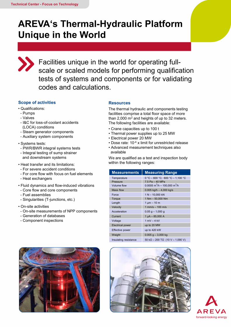
AREVA‘s Thermal-Hydraulic Platform Unique in the World
Facilities unique in the world for operating full-scale or scaled models for performing qualification tests of systems and components or for validating codes and calculations.
Technical Center - Focus on Technology
Scope of activities • Qualifications: - Pumps - Valves - I&C for loss-of-coolant accidents (LOCA) conditions - Steam generator components - Auxiliary system components
• Systems tests: - PWR/BWR integral systems tests - Integral testing of sump strainer and downstream systems
• Heat transfer and its limitations: - For severe accident conditions - For core flow with focus on fuel elements - Heat exchangers
• Fluid dynamics and flow-induced vibrations - Core flow and core components - Fuel assemblies - Singularities (T-junctions, etc.)
• On-site activities - On-site measurements of NPP components - Generation of databases - Component inspections
Resources The thermal hydraulic and components testing facilities comprise a total floor space of more than 2,000 m2 and heights of up to 32 meters. The following facilities are available: • Crane capacities up to 100 t • Thermal power supplies up to 25 MW • Electrical power 20 MW • Dose rate: 10-4 x limit for unrestricted release • Advanced measurement techniques also available We are qualified as a test and inspection body within the following ranges:
Measurements Measuring Range Temperature 0 °C – 600 °C; 600 °C – 1,100 °C Pressure 7.5 Pa – 40 MPa Volume flow 0.0005 m3/h – 100,000 m3/h
Mass flow 0.005 kg/h – 4,000 kg/s
Force 1 N – 10,000 kN Torque 1 Nm – 50,000 Nm Length 1 μm – 10 m Velocity 1 mm/s – 100 m/s Acceleration 0.05 g – 1,000 g
Current 1 μA – 85,000 A Voltage 1 mV – 4 kV Electrical power up to 20 MW
Effective power up to 420 kW
Weight 0.005 g – 3,000 kg
Insulating resistance 50 kΩ – 200 TΩ (10 V – 1,090 V)
AREVA GMBH Your contact: [email protected]
Thermal-Hydraulic Platform Unique in the World
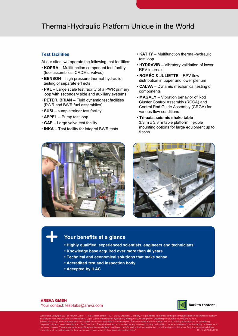
Test facilities At our sites, we operate the following test facilities: • KOPRA – Multifunction component test facility (fuel assemblies, CRDMs, valves) • BENSON – high pressure thermal-hydraulic testing of separate eff ects • PKL – Large scale test facility of a PWR primary loop with secondary side and auxiliary systems • PETER, BRIAN – Fluid dynamic test facilities (PWR and BWR fuel assemblies) • SUSI – sump strainer test facility • APPEL – Pump test loop • GAP – Large valve test facility • INKA – Test facility for integral BWR tests
• KATHY – Multifunction thermal-hydraulic test loop • HYDRAVIB – Vibratory validation of lower RPV internals • ROMÉO & JULIETTE – RPV flow distribution in upper and lower plenum • CALVA – Dynamic mechanical testing of components • MAGALY – Vibration behavior of Rod Cluster Control Assembly (RCCA) and Control Rod Guide Assembly (CRGA) for various flow conditions • Tri-axial seismic shake table – 3.3 m x 3.3 m table platform, flexible mounting options for large equipment up to 9 tons
Your benefits at a glance • Highly qualified, experienced scientists, engineers and technicians • Knowledge base acquired over more than 40 years • Technical and economical solutions that make sense • Accredited test and inspection body • Accepted by ILAC
„Editor and Copyright (2015): AREVA GmbH – Paul-Gossen-Straße 100 – 91052 Erlangen, Germany. It is prohibited to reproduce the present publication in its entirety or partially in whatever form without prior written consent. Legal action may be taken against any infringer and/or any person breaching the aforementioned prohibitions. Subject to change without notice, errors excepted. Illustrations may differ from the original. The statements and information contained in this publication are for advertising purposes only and do not constitute an offer of contract. They shall neither be construed as a guarantee of quality or durability, nor as warranties of merchantability or fitness for a particular purpose. These statements, even if they are future-orientated, are based on information that was available to us at the date of publication. Only the terms of individual contracts shall be authoritative for type, scope and characteristics of our products and services.” G-127-V3-13-ENGPB
Back to content

Qualification of Components Infrastructure for full-scale thermal-hydraulic test facilities
Powerful and flexible infrastructure supplies full-scale test facilities with energy, high pressure steam, heat removal capability and demineralized water
Technical Center - Focus on Technology
The challenge Large test facilities require a huge amount of steam and electrical energy. An adequate infrastructure must be able to supply this energy flexibly and reliably. The infrastructure must not only supply this energy, but also remove the energy that has been added. A central water supply of treated and demineralized water is a prerequisite for operating such loops.
The solution At the center of the component qualifi cation facility is an infrastructure that can supply the various fullscale test loops with the required energy and fluids with the required properties.
The infrastructure offers:
• High-pressure steam-supply Benson boiler generates steam used for performing valve tests and LOCA qualification of safety-related components and for supporting passive safetysystem development.
• 20 MW DC power supply has direct access to the German grid and is used to perform critical heat flux tests using electrically heated fuel assemblies for BWRs and PWRs.
• Two heat removal systems (High- and low-pressure)
• Water treatment plant supplies demineralized water from two independent parallel lines.
Infrastructure • Benson boiler steam supply: 520 °C, 187 bar, 25 t/h • Electrical DC power supply: 20 MW, 83 kA • High-pressure heat removal system: 25 MW, 25 bar • Low-pressure heat removal system: 8 MW, 80 °C • Water treatment and demineralization plant: 2 x 6m3/h, < 0,2 μS/cm • Test section lines DN 150, 250 (8”, 10”)
The new Benson boiler is installed in the building
Powerful and flexible infrastructure The powerful infrastructure allows erection and operation of test facilities unique in the world, in many cases at full scale.
With this infrastructure supporting the test facilities, AREVA is able to qualify components such as feedwater supply and main steam isolation valves under full-scale conditions at mass flows of up to 4,000 kg/s.
Your benefits at a glance
Qualification of Components Infrastructure for full-scale thermal-hydraulic test facilities
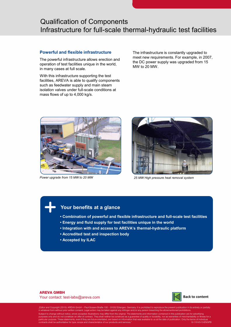
Power upgrade from 15 MW to 20 MW
The infrastructure is constantly upgraded to meet new requirements. For example, in 2007, the DC power supply was upgraded from 15 MW to 20 MW.
25 MW High pressure heat removal system
• Combination of powerful and flexible infrastructure and full-scale test facilities • Energy and fluid supply for test facilities unique in the world • Integration with and access to AREVA’s thermal-hydraulic platform • Accredited test and inspection body • Accepted by ILAC
AREVA GMBH Your contact: [email protected]
„Editor and Copyright (2015): AREVA GmbH – Paul-Gossen-Straße 100 – 91052 Erlangen, Germany. It is prohibited to reproduce the present publication in its entirety or partially in whatever form without prior written consent. Legal action may be taken against any infringer and/or any person breaching the aforementioned prohibitions.
Subject to change without notice, errors excepted. Illustrations may differ from the original. The statements and information contained in this publication are for advertising purposes only and do not constitute an offer of contract. They shall neither be construed as a guarantee of quality or durability, nor as warranties of merchantability or fitness for a particular purpose. These statements, even if they are future-orientated, are based on information that was available to us at the date of publication. Only the terms of individual contracts shall be authoritative for type, scope and characteristics of our products and services.” G-110-V3-13-ENGPB
Back to content
Fluid-Dynamic and Thermal- Hydraulic Analysis
Full scope of analysis methods solves problems in the fields of fluid dynamics and thermal hydraulics
Technical Center - Focus on Technology
Solution orientation Focused on solutions including: • Describing or confi rming system or component function in our capacity as an accredited test and inspection body • Proposing component or system modifications • Developing correlations or models • Developing databases in our capacity as an accredited test body • Developing user-friendly test programs The most appropriate process is chosen following analysis of the task, following the diagram below. Numerical and analytical methods are crucial for providing a direct solution or for supporting the test related processes. Our capabilities relevant to these goals are: • Performing numerical and analytical analyse • Developing physical models and related programs • Programming graphical user interfaces (GUI)
Program and physical model development Specially developed, customized programs or physical models facilitate the solution of a task, enabling the customer to optimize his own processes. The programs and models can be based on databases from test results, or on one of the following: • Customized interfaces to OpenFOAM that employ a user-friendly interface for performing, visualizing and interpreting calculations. • Development of 1-D codes, e.g., for two-phase flow network programs using correlations derived from tests • Physical model development, e.g., for CFD programs.
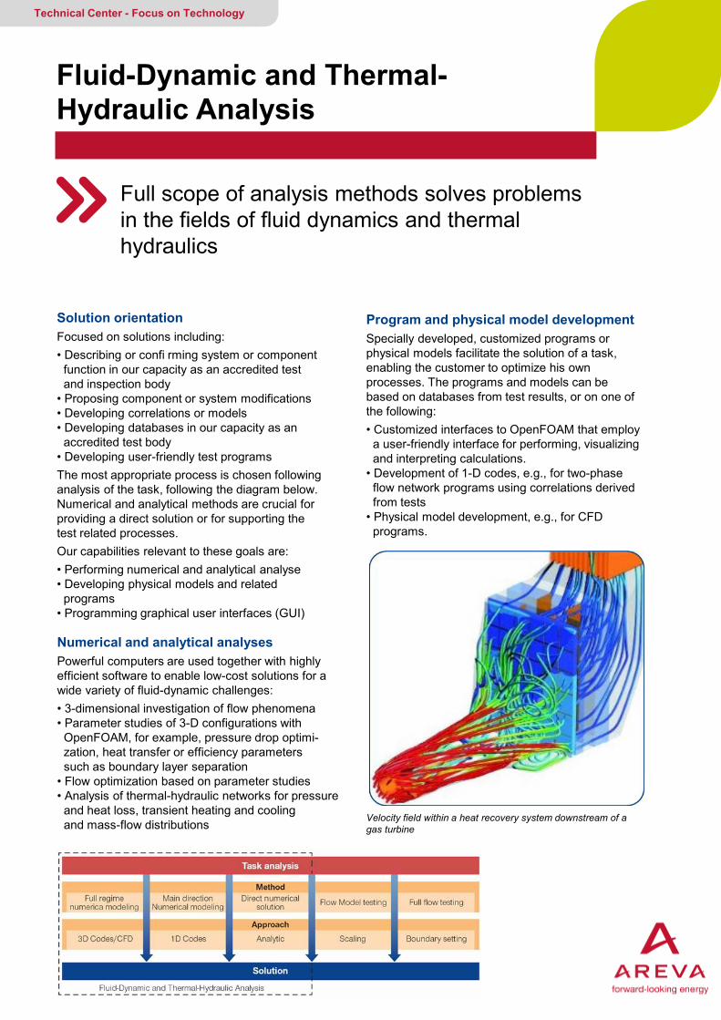
Numerical and analytical analyses Powerful computers are used together with highly efficient software to enable low-cost solutions for a wide variety of fluid-dynamic challenges: • 3-dimensional investigation of flow phenomena • Parameter studies of 3-D configurations with OpenFOAM, for example, pressure drop optimi- zation, heat transfer or efficiency parameters such as boundary layer separation • Flow optimization based on parameter studies • Analysis of thermal-hydraulic networks for pressure and heat loss, transient heating and cooling and mass-flow distributions Velocity field within a heat recovery system downstream of a
gas turbine
AREVA GMBH Your contact: [email protected]
Fluid-Dynamic and Thermal-Hydraulic Analysis
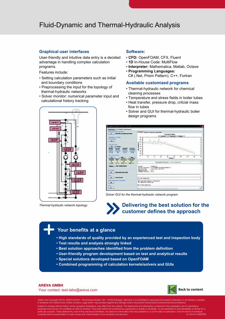
Graphical user interfaces User-friendly and intuitive data entry is a decided advantage in handling complex calculation programs. Features include: • Setting calculation parameters such as initial and boundary conditions • Preprocessing the input for the topology of thermal-hydraulic networks • Solver monitor: numerical parameter input and calculational history tracking
Your benefits at a glance
Software: • CFD: OpenFOAM, CFX, Fluent • 1D In-House Code: MultiFlow • Interpreter: Mathematica, Matlab, Octave • Programming Languages: C# (.Net, Prism Pattern), C++, Fortran
Available customized programs • Thermal-hydraulic network for chemical cleaning processes • Temperature and stress fields in boiler tubes • Heat transfer, pressure drop, critcial mass flow in tubes • Solver and GUI for thermal-hydraulic boiler design programs
Solver GUI for the thermal-hydraulic network program
Thermal-hydraulic network topology Delivering the best solution for the customer defines the approach
• High standards of quality provided by an experienced test and inspection body • Test results and analysis strongly linked • Best solution approaches identified from the problem definition • User-friendly program development based on test and analytical results • Special solutions developed based on OpenFOAM • Combined programming of calculation kernels/solvers and GUIs
„Editor and Copyright (2015): AREVA GmbH – Paul-Gossen-Straße 100 – 91052 Erlangen, Germany. It is prohibited to reproduce the present publication in its entirety or partially in whatever form without prior written consent. Legal action may be taken against any infringer and/or any person breaching the aforementioned prohibitions.
Subject to change without notice, errors excepted. Illustrations may differ from the original. The statements and information contained in this publication are for advertising purposes only and do not constitute an offer of contract. They shall neither be construed as a guarantee of quality or durability, nor as warranties of merchantability or fitness for a particular purpose. These statements, even if they are future-orientated, are based on information that was available to us at the date of publication. Only the terms of individual contracts shall be authoritative for type, scope and characteristics of our products and services.” G-143-V2-13-ENGPB
Back to content
Similitude Tests Optimization of components and processes
Fluid-dynamic and thermal-hydraulic tests validate and optimize design
Technical Center - Focus on Technology
The challenge In industrial plants, industrial processes and industrial engines, complex system as well as individual components must be capable of performing their designated function at all times during normal operation as well as under other, specific conditions
The solution AREVA validates and optimizes component design using fluid-dynamic and thermal-hydraulic tests. • The first step in optimizing the tests and costs is to identify the relevant physical phenomena. The most relevant laws of similitude and non-dimensional numbers for designing the test are then defined. • The second step is to define the scale of the mock-up and the test fluid to reduce the costs. Numerical codes (EF, CFD) simulate component and system responses for nominal or accident conditions. However, experimental verification is still indispensable for providing input data and validating code results.
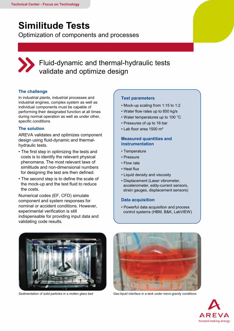
Test parameters • Mock-up scaling from 1:15 to 1:2 • Water flow rates up to 850 kg/s • Water temperatures up to 100 °C • Pressures of up to 16 bar • Lab floor area 1500 m² Measured quantities and instrumentation • Temperature • Pressure • Flow rate • Heat flux • Liquid density and viscosity • Displacement (Laser vibrometer, accelerometer, eddy-current sensors, strain gauges, displacement sensors) Data acquisition • Powerful data acquisition and process control systems (HBM, B&K, LabVIEW)
Sedimentation of solid particles in a molten glass bed Gas-liquid interface in a tank under micro-gravity conditions

AREVA GMBH Your contact: [email protected]
Similitude Tests
Test experience Qualification of nuclear power plant components • EPR™ reactor pressure vessel pressure losses, flow mixing and flow-rate distribution • Thermal stratification and heat transfer in mixing areas • Jules Horowitz Reactor facility: flow-induced vibrations of reactor vessel internals • EPR™: flow-induced vibrations of the RPV internals Process engineering experiments • Sedimentation of particles in nuclear-waste vitrification • Fuel tank optimization for ballistic phase of ARIANE 5 rocket
Your benefits at a glance
EPR™ reactor pressure vessel mock-up: Juliette
EPR™ reactor pressure vessel mock-up: Romeo
• Well-equipped laboratory using sophisticated measurement systems • More than thirty years of experience in testing and analysis • Applicable to nuclear and renewable energy projects • Integration with and access to AREVA’s thermal-hydraulic platform
Experience in all fields of fluid mechanics
„Editor and Copyright (2015): AREVA GmbH – Paul-Gossen-Straße 100 – 91052 Erlangen, Germany. It is prohibited to reproduce the present publication in its entirety or partially in whatever form without prior written consent. Legal action may be taken against any infringer and/or any person breaching the aforementioned prohibitions.
Subject to change without notice, errors excepted. Illustrations may differ from the original. The statements and information contained in this publication are for advertising purposes only and do not constitute an offer of contract. They shall neither be construed as a guarantee of quality or durability, nor as warranties of merchantability or fitness for a particular purpose. These statements, even if they are future-orientated, are based on information that was available to us at the date of publication. Only the terms of individual contracts shall be authoritative for type, scope and characteristics of our products and services.” G-168-V2-13-ENGPB
Back to content
AREVA’s Thermal-Hydraulic Separate Effect Tests / BENSON
Single-phase and two-phase flow applications investigated up to supercritical pressure conditions
Technical Center - Focus on Technology
The challenge Investigating a wide variety of separate thermal hydraulic effects, while achieving maximum operational flexibility for single- and two-phase operations at high temperature and high pressure conditions up to supercritical pressure conditions
The solution AREVA operates a high-pressure test facility whose flexibility and range of applications make it unique in the world. All kinds of test objects can be installed in the facility and heated using a powerful direct-current power supply. A wide variety of separate thermal-hydraulic eff ects are investigated, such as: • Heat transfer • Critical heat flux • Water/steam distribution
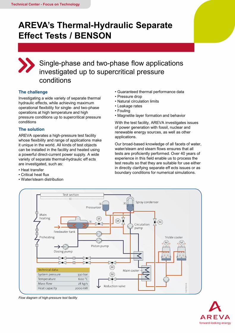
Flow diagram of high-pressure test facility
• Guaranteed thermal performance data • Pressure drop • Natural circulation limits • Leakage rates • Fouling • Magnetite layer formation and behavior
With the test facility, AREVA investigates issues of power generation with fossil, nuclear and renewable energy sources, as well as other applications.
Our broad-based knowledge of all facets of water, water/steam and steam flows ensures that all tests are proficiently performed. Over 40 years of experience in this field enable us to process the test results so that they are suitable for use either in directly clarifying separate eff ects issues or as boundary conditions for numerical simulations.
AREVA GMBH Your contact: [email protected]
High Pressure Test Facility / BENSON
Examples of power generation applications Reactor system thermal-hydraulics • Separate effect tests for condensers of new generation reactors • Heat transfer tests on a steam generator tube for fouling aspects (C.N.Trillo, Spain) • Investigations of fuel assembly cladding tube temperatures and pressure drop using a 5x5 rod bundle from a PWR • Studies of the TMI 2 accident • Verification of the cooling function in the EPR core melt spreading area • KERENA exterior vessel cooling concept safety margins
Renewable energy applications • Investigation of heat transfer and flow behavior for direct solar steam generation by absorber/ evaporator tubes in CSP plants
BENSON steam generators • Perform experimental investigations of heat transfer and pressure drop in vertical, inclined and horizontal smooth and rifled tubes heated either uniformly or on one side for BENSON licenses • Experimental results used to develop and validate the computer codes WATHUN and DRUBEN. These codes function as subroutines in boiler design programs in the fossil-fired power generation field. • Largest database in the world for CHF, heat transfer and pressure drop
Your benefits at a glance
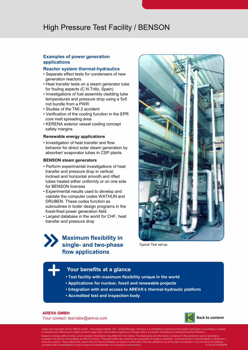
Typical Test set-up
• Test facility with maximum flexibility unique in the world • Applications for nuclear, fossil and renewable projects • Integration with and access to AREVA’s thermal-hydraulic platform • Accredited test and inspection body
Maximum flexibility in single- and two-phase flow applications
„Editor and Copyright (2015): AREVA GmbH – Paul-Gossen-Straße 100 – 91052 Erlangen, Germany. It is prohibited to reproduce the present publication in its entirety or partially in whatever form without prior written consent. Legal action may be taken against any infringer and/or any person breaching the aforementioned prohibitions.
Subject to change without notice, errors excepted. Illustrations may differ from the original. The statements and information contained in this publication are for advertising purposes only and do not constitute an offer of contract. They shall neither be construed as a guarantee of quality or durability, nor as warranties of merchantability or fitness for a particular purpose. These statements, even if they are future-orientated, are based on information that was available to us at the date of publication. Only the terms of individual contracts shall be authoritative for type, scope and characteristics of our products and services.” G-142-V2-13-ENGPB
Back to content

Vibrations and Mechanical Tests Optimization of Power Plant Components
Separate fluid-dynamic and mechanical tests for nuclear power plants
Technical Center - Focus on Technology
The challenge In nuclear power plants, complex plant systems and individual components must be capable of performing their designated functions at all times during normal operation as well as under any postulated accident condition. Carefully designing and simulating the mechanical component response is possible using FE (finite element) codes, but to be truly dependable, the results of these codes must be validated.
The solution Mechanical and vibration tests on full-scale compo- nent prototypes make the following possible: • Providing input data about links and connections between the elements of a component • Validating the FE models and component simulations • Assessing the manufacturing process
Fuel assembly instrumented with strain gages and displacement sensors on CALVA Bench
Test parameters • Flow rate up to 1000 m3/h • Shaking devices with forces up to 2000 N • Temperature up to 100 °C • Pressure up to 16 bars
Measurements and instrumentation • Temperature, pressure, flow rate • Accelerometer, • Displacement (Laser vibrometer, accelerometer, Eddy current sensors, strain gauges, displacement sensor)
Data acquisition • Powerful data acquisition and process control systems (HBM, B&K, LabVIEW)
MAGALY bench: Flow-induced vibrations of control rod guide assembly and control rod cluster assembly
AREVA GMBH Your contact: [email protected]
Vibrations and Mechanical Tests
Test experience Qualification of nuclear power plant components
CALVA bench • Mechanical characterisation of EPR™ control rod guide assembly • EPR™ CRGA vibration fatigue tests, • EPR™ CRGA loss of function test • Mechanical characterisation and modal analysis of 14-ft fuel assembly
MAGALY bench • Flow-induced vibration of control rod cluster assembly for - EPR™ - 1300 MWe French plants
SOPHIE bench • Vibration behavior of steam generator tubes
Your benefits at a glance
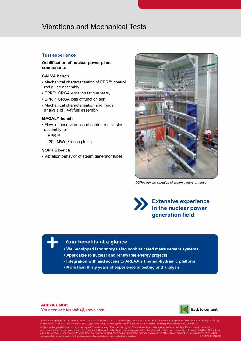
SOPHI bench: vibration of steam generator tubes
• Well-equipped laboratory using sophisticated measurement systems • Applicable to nuclear and renewable energy projects • Integration with and access to AREVA’s thermal-hydraulic platform • More than thirty years of experience in testing and analysis
Extensive experience in the nuclear power generation field
„Editor and Copyright (2015): AREVA GmbH – Paul-Gossen-Straße 100 – 91052 Erlangen, Germany. It is prohibited to reproduce the present publication in its entirety or partially in whatever form without prior written consent. Legal action may be taken against any infringer and/or any person breaching the aforementioned prohibitions.
Subject to change without notice, errors excepted. Illustrations may differ from the original. The statements and information contained in this publication are for advertising purposes only and do not constitute an offer of contract. They shall neither be construed as a guarantee of quality or durability, nor as warranties of merchantability or fitness for a particular purpose. These statements, even if they are future-orientated, are based on information that was available to us at the date of publication. Only the terms of individual contracts shall be authoritative for type, scope and characteristics of our products and services.” G-169-V2-13-ENGPB
Back to content
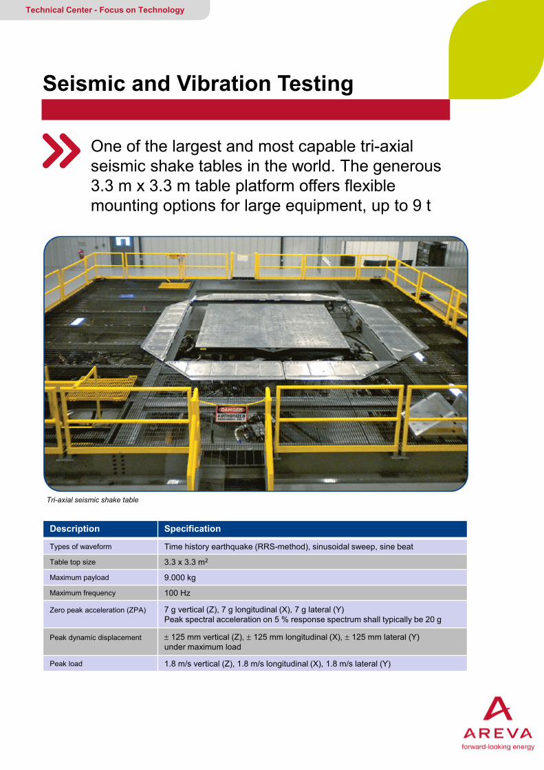
Seismic and Vibration Testing
One of the largest and most capable tri-axial seismic shake tables in the world. The generous 3.3 m x 3.3 m table platform offers flexible mounting options for large equipment, up to 9 t
Technical Center - Focus on Technology
Tri-axial seismic shake table
Description Specification
Types of waveform Time history earthquake (RRS-method), sinusoidal sweep, sine beat
Table top size 3.3 x 3.3 m2
Maximum payload 9.000 kg
Maximum frequency 100 Hz
Zero peak acceleration (ZPA)
7 g vertical (Z), 7 g longitudinal (X), 7 g lateral (Y) Peak spectral acceleration on 5 % response spectrum shall typically be 20 g
Peak dynamic displacement
± 125 mm vertical (Z), ± 125 mm longitudinal (X), ± 125 mm lateral (Y) under maximum load
Peak load 1.8 m/s vertical (Z), 1.8 m/s longitudinal (X), 1.8 m/s lateral (Y)
AREVA GMBH Your contact: [email protected]
Seismic and Vibration Testing
Safety is our number one priority! Customers communicate with the control room and witness test programs from the safety of the conference room overlooking the shake table. Test specimens are received by truck through a large overhead door, and moved to the seismic shake table by a 5-ton overhead crane.
Data acquisition and testing support Calibrated data acquisition equipment includes accelerometers, chatter monitoring, and strain gauges depending on the application. The lab is equipped with high voltage AC/DC power supplies and other services allowing the operation and monitoring of test specimens during testing.
Mechanical vibration testing and aging For smaller items weighing up to 150 kg, our single- axis electrodynamic shake table provides a mechanical and seismic testing capabilities, delivering 9 kN of sine force at velocities of 2 m/s.
Your benefits at a glance
Qualification of valves, primary circuit internals, I&C equipment
• Hydraulic and electro-dynamic shake tables • Full-service lab, supported by AREVA’s engineering capabilities and mechanical design • Quality assurance according to e.g.: Appendix B, NQA-1 and ISO approved quality program
„Editor and Copyright (2015): AREVA GmbH – Paul-Gossen-Straße 100 – 91052 Erlangen, Germany. It is prohibited to reproduce the present publication in its entirety or partially in whatever form without prior written consent. Legal action may be taken against any infringer and/or any person breaching the aforementioned prohibitions.
Subject to change without notice, errors excepted. Illustrations may differ from the original. The statements and information contained in this publication are for advertising purposes only and do not constitute an offer of contract. They shall neither be construed as a guarantee of quality or durability, nor as warranties of merchantability or fitness for a particular purpose. These statements, even if they are future-orientated, are based on information that was available to us at the date of publication. Only the terms of individual contracts shall be authoritative for type, scope and characteristics of our products and services.” G-302-V1-14-ENGPB
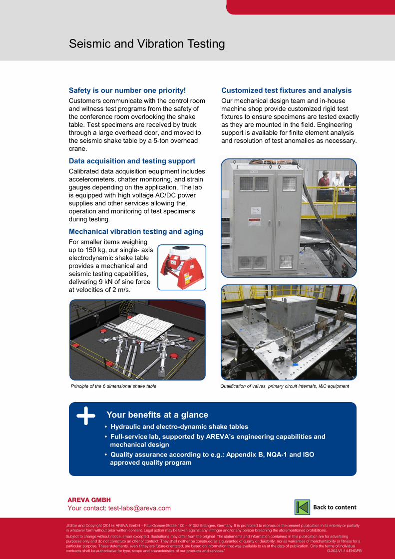
Customized test fixtures and analysis Our mechanical design team and in-house machine shop provide customized rigid test fixtures to ensure specimens are tested exactly as they are mounted in the field. Engineering support is available for finite element analysis and resolution of test anomalies as necessary.
Principle of the 6 dimensional shake table
Back to content
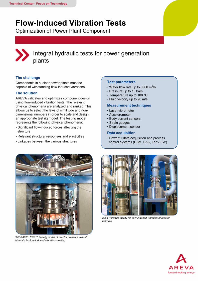
Flow-Induced Vibration Tests Optimization of Power Plant Component
Integral hydraulic tests for power generation plants
Technical Center - Focus on Technology
The challenge Components in nuclear power plants must be capable of withstanding flow-induced vibrations.
The solution AREVA validates and optimizes component design using flow-induced vibration tests. The relevant physical phenomena are analyzed and ranked. This allows us to select the laws of similitude and non-dimensional numbers in order to scale and design an appropriate test rig model. The test rig model represents the following physical phenomena: • Significant flow-induced forces affecting the structure • Relevant structural responses and elasticities • Linkages between the various structures
HYDRAVIB: EPR™ test-rig model of reactor pressure vessel internals for flow-induced vibrations testing
Test parameters • Water flow rate up to 3000 m3/h • Pressure up to 16 bars • Temperature up to 100 °C • Fluid velocity up to 20 m/s
Measurement techniques • Laser vibrometer • Accelerometer • Eddy current sensors • Strain gauges • Displacement sensor
Data acquisition • Powerful data acquisition and process control systems (HBM, B&K, LabVIEW)
Jules Horowitz facility for flow-induced vibration of reactor internals.
AREVA GMBH Your contact: [email protected]
Flow-Induced Vibration Tests
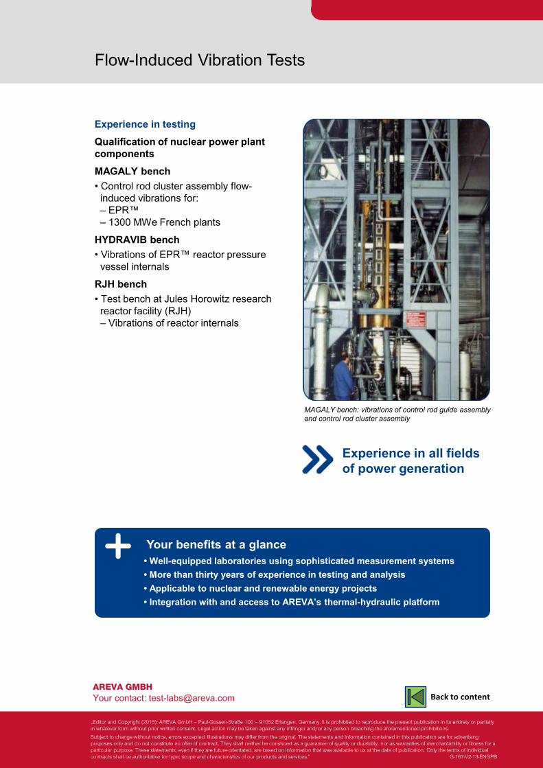
Experience in testing Qualification of nuclear power plant components MAGALY bench • Control rod cluster assembly flow- induced vibrations for: – EPR™ – 1300 MWe French plants
HYDRAVIB bench • Vibrations of EPR™ reactor pressure vessel internals
RJH bench • Test bench at Jules Horowitz research reactor facility (RJH) – Vibrations of reactor internals
Your benefits at a glance
MAGALY bench: vibrations of control rod guide assembly and control rod cluster assembly
• Well-equipped laboratories using sophisticated measurement systems • More than thirty years of experience in testing and analysis • Applicable to nuclear and renewable energy projects • Integration with and access to AREVA’s thermal-hydraulic platform
Experience in all fields of power generation
„Editor and Copyright (2015): AREVA GmbH – Paul-Gossen-Straße 100 – 91052 Erlangen, Germany. It is prohibited to reproduce the present publication in its entirety or partially in whatever form without prior written consent. Legal action may be taken against any infringer and/or any person breaching the aforementioned prohibitions.
Subject to change without notice, errors excepted. Illustrations may differ from the original. The statements and information contained in this publication are for advertising purposes only and do not constitute an offer of contract. They shall neither be construed as a guarantee of quality or durability, nor as warranties of merchantability or fitness for a particular purpose. These statements, even if they are future-orientated, are based on information that was available to us at the date of publication. Only the terms of individual contracts shall be authoritative for type, scope and characteristics of our products and services.” G-167-V2-13-ENGPB
Back to content
Flow Model Tests Optimization of Power Plant Components and Processes
Fluid-dynamic and thermal-hydraulic tests provided for all power generation fields
Technical Center - Focus on Technology
The challenge Whether power plants run on nuclear or fossil fuels or on renewable energy sources, the complex plant systems and individual components must be capable of performing their designated functions under normal and accident operating conditions.
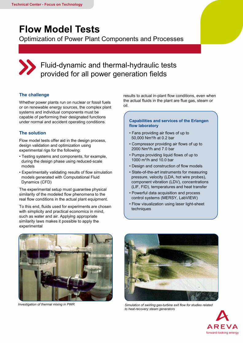
Investigation of thermal mixing in PWR Simulation of swirling gas-turbine exit flow for studies related to heat-recovery steam generators
Capabilities and services of the Erlangen flow laboratory
• Fans providing air flows of up to 50,000 Nm³/h at 0.2 bar • Compressor providing air flows of up to 2000 Nm³/h and 7.0 bar • Pumps providing liquid flows of up to 1000 m³/h and 10.0 bar • Design and construction of flow models • State-of-the-art instruments for measuring pressure, velocity (LDA, hot wire probes), component vibration (LDV), concentrations (LIF, FID), temperatures and heat transfer • Powerful data acquisition and process control systems (MERSY, LabVIEW) • Flow visualization using laser light-sheet techniques
results to actual in-plant flow conditions, even when the actual fluids in the plant are flue gas, steam or oil.
The solution Flow model tests offer aid in the design process, design validation and optimization using experimental rigs for the following: • Testing systems and components, for example, during the design phase using reduced-scale models • Experimentally validating results of flow simulation models generated with Computational Fluid Dynamics (CFD)
The experimental setup must guarantee physical similarity of the modeled flow phenomena to the real flow conditions in the actual plant equipment.
To this end, fluids used for experiments are chosen with simplicity and practical economics in mind, such as water and air. Applying appropriate similarity laws makes it possible to apply the experimental

AREVA GMBH Your contact: [email protected]
Flow Model Tests
References Fluid dynamics experiments • KERENA safety concept: - Water/air experiments simulating the cooling of the exterior RPV for postulated core-melt accidents - Experiments investigating boron dilution in the reactor core (FABIS Project) • Experiments for NPPs, e.g., - Angra 1 (Brazil) - Brokdorf (Germany) - Stade (Germany) • Experiments for fossil-fired power plants, e.g., - Cottam (Great Britain) - Kansas City (USA) • SCR plants with PARMIX and TURBOMIX static mixers, e.g., - Brandon Shores (USA) - BASF (Germany)
Process engineering experiments • Explosive limits of fuels for combined-cycle power plants (natural gas and coal gas) • Explosive limits of natural gas for gas distribution networks operated by the German utility Ruhrgas AG.
Your benefits at a glance • Well-equipped laboratory with sophisticated measurement systems
• Available for nuclear, fossil and renewable fuels projects
• Integration with and access to AREVA’s thermal-hydraulic platform
• Accredited test and inspection body
Model used for optimizing a DeNOX reactor for a coal- fired power plant
Experience in all fields of power generation
„Editor and Copyright (2015): AREVA GmbH – Paul-Gossen-Straße 100 – 91052 Erlangen, Germany. It is prohibited to reproduce the present publication in its entirety or partially in whatever form without prior written consent. Legal action may be taken against any infringer and/or any person breaching the aforementioned prohibitions.
Subject to change without notice, errors excepted. Illustrations may differ from the original. The statements and information contained in this publication are for advertising purposes only and do not constitute an offer of contract. They shall neither be construed as a guarantee of quality or durability, nor as warranties of merchantability or fitness for a particular purpose. These statements, even if they are future-orientated, are based on information that was available to us at the date of publication. Only the terms of individual contracts shall be authoritative for type, scope and characteristics of our products and services.” G-145-V2-13-ENGPB
Back to content

Test Facilities For Power and Process Industry Applications
Turnkey delivery specifically tailors design of test facilities for power and process industry applications to customer needs
Technical Center - Focus on Technology
Full scope of services AREVA is qualified to deliver a full scope of test facility installation services according to customer demands. The full scope includes: • Project Management • Planning • Design • Construction • Electrical installation • Data acquisition • Commissioning
Design and construction benefits AREVA is highly qualified to design and construct test facilities because of our: • Experience in designing test facilities gained from modifying our own experimental rigs and from building several facilities for customers • Well-equipped workshops (elaborate welding technologies, 400 m² of workshop area, crane loads up to 100 tons) • Extensive knowledge in identifying and monitoring special vendors for non-standard components.
Rig for materials testing in corrosive environment Example of construction
• Experience communicating with authorities and expert organizations for jobs requiring conform- ance to national and international standards • Expertise designing high pressure and temperature facilities for conditions up to 300 bar and 1000 °C.
AREVA GMBH Your contact: [email protected]
Test Facilities For Power and Process Industry Applications
Test facilities delivered ready-to-use This includes implementation of: • Measuring instruments • Automated process control equipment • Design and assembly of all electronic components • Data acquisition systems • Online visualization
Powerful and cost-effective I&C implementation Because of our extensive experience in manufacturing and operating our own complex test facilities, we always put the user’s needs in the foreground when programming the control systems. The user’s needs play an important part in designing user interfaces reduced to the bare essentials or in individually adapting process visualizations.
Your benefits at a glance • One-stop design and assembly of experimental rigs created according to customer specifications • Measurement and control systems appropriately selected • Standard parts employed or adapted cost-effectively • In-house programming assures optimal configuration of requested • Data acquisition system features high degree of interconnectivity • Process visualization customized for the specific application • Systems commissioned on-the-spot
Fuel cell online process visualization
Data acquisition delivered ready-to-use • Graphical user interface • Automatic equipment protection • Adjustable data acquisition and recording intervals • Existing measurement devices simply triggered • Customer-specific user interfaces
Visualization of temperature profile
„Editor and Copyright (2015): AREVA GmbH – Paul-Gossen-Straße 100 – 91052 Erlangen, Germany. It is prohibited to reproduce the present publication in its entirety or partially in whatever form without prior written consent. Legal action may be taken against any infringer and/or any person breaching the aforementioned prohibitions.
Subject to change without notice, errors excepted. Illustrations may differ from the original. The statements and information contained in this publication are for advertising purposes only and do not constitute an offer of contract. They shall neither be construed as a guarantee of quality or durability, nor as warranties of merchantability or fitness for a particular purpose. These statements, even if they are future-orientated, are based on information that was available to us at the date of publication. Only the terms of individual contracts shall be authoritative for type, scope and characteristics of our products and services.” G-140-V2-13-ENGPB
Back to content
Karlstein Integral Test Stand (INKA) Qualification of Components
Facility tests containment safety concepts under accident conditions, supports experimental analysis of specific scenarios and supplies data for code validation
Technical Center - Focus on Technology
The challenge Numerical codes modeling system and containment are often used to analyze accident scenarios in light water reactors. These computer codes use thermal-hydraulic correlations that are derived from active safety systems. With the use of passive safety systems, however, the need to validate and optimize these codes arises.
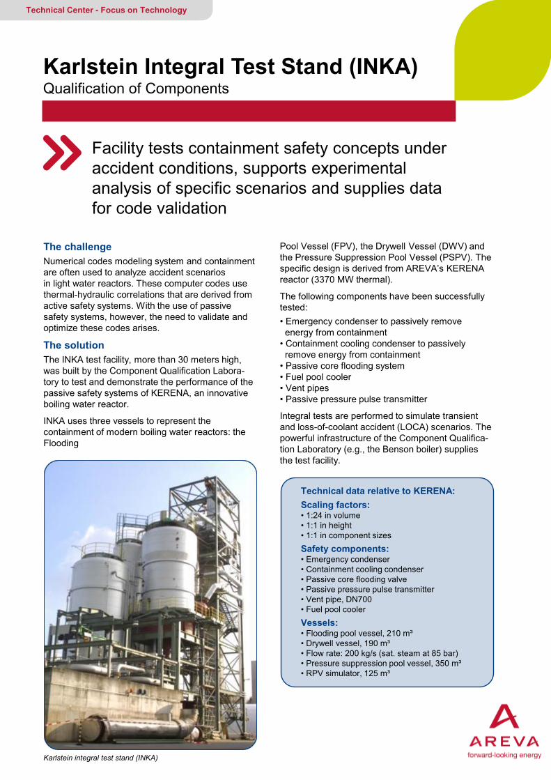
The solution The INKA test facility, more than 30 meters high, was built by the Component Qualification Labora- tory to test and demonstrate the performance of the passive safety systems of KERENA, an innovative boiling water reactor.
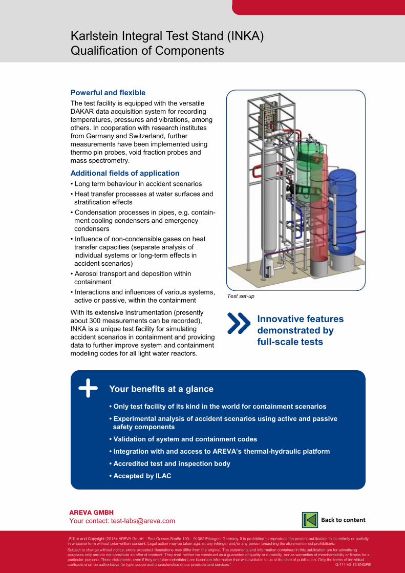
INKA uses three vessels to represent the containment of modern boiling water reactors: the Flooding
Pool Vessel (FPV), the Drywell Vessel (DWV) and the Pressure Suppression Pool Vessel (PSPV). The specific design is derived from AREVA’s KERENA reactor (3370 MW thermal).
The following components have been successfully tested: • Emergency condenser to passively remove energy from containment • Containment cooling condenser to passively remove energy from containment • Passive core flooding system • Fuel pool cooler • Vent pipes • Passive pressure pulse transmitter
Integral tests are performed to simulate transient and loss-of-coolant accident (LOCA) scenarios. The powerful infrastructure of the Component Qualifica-tion Laboratory (e.g., the Benson boiler) supplies the test facility.
Technical data relative to KERENA: Scaling factors: • 1:24 in volume • 1:1 in height • 1:1 in component sizes Safety components: • Emergency condenser • Containment cooling condenser • Passive core flooding valve • Passive pressure pulse transmitter • Vent pipe, DN700 • Fuel pool cooler Vessels: • Flooding pool vessel, 210 m³ • Drywell vessel, 190 m³ • Flow rate: 200 kg/s (sat. steam at 85 bar) • Pressure suppression pool vessel, 350 m³ • RPV simulator, 125 m³
Karlstein integral test stand (INKA)
AREVA GMBH Your contact: [email protected]
Karlstein Integral Test Stand (INKA) Qualification of Components
Powerful and flexible The test facility is equipped with the versatile DAKAR data acquisition system for recording temperatures, pressures and vibrations, among others. In cooperation with research institutes from Germany and Switzerland, further measurements have been implemented using thermo pin probes, void fraction probes and mass spectrometry.
Additional fields of application • Long term behaviour in accident scenarios • Heat transfer processes at water surfaces and stratification effects • Condensation processes in pipes, e.g. contain- ment cooling condensers and emergency condensers • Influence of non-condensible gases on heat transfer capacities (separate analysis of individual systems or long-term effects in accident scenarios) • Aerosol transport and deposition within containment • Interactions and influences of various systems, active or passive, within the containment
With its extensive Instrumentation (presently about 300 measurements can be recorded), INKA is a unique test facility for simulating accident scenarios in containment and providing data to further improve system and containment modeling codes for all light water reactors.
Your benefits at a glance
• Only test facility of its kind in the world for containment scenarios
• Experimental analysis of accident scenarios using active and passive safety components
• Validation of system and containment codes
• Integration with and access to AREVA’s thermal-hydraulic platform
• Accredited test and inspection body
• Accepted by ILAC
Test set-up
Innovative features demonstrated by full-scale tests
„Editor and Copyright (2015): AREVA GmbH – Paul-Gossen-Straße 100 – 91052 Erlangen, Germany. It is prohibited to reproduce the present publication in its entirety or partially in whatever form without prior written consent. Legal action may be taken against any infringer and/or any person breaching the aforementioned prohibitions.
Subject to change without notice, errors excepted. Illustrations may differ from the original. The statements and information contained in this publication are for advertising purposes only and do not constitute an offer of contract. They shall neither be construed as a guarantee of quality or durability, nor as warranties of merchantability or fitness for a particular purpose. These statements, even if they are future-orientated, are based on information that was available to us at the date of publication. Only the terms of individual contracts shall be authoritative for type, scope and characteristics of our products and services.” G-111-V3-13-ENGPB
Back to content
AREVA’s PWR Integral System Test Facility (PKL)
Model of a 4-loop PWR allows transient tests and parameter studies
Technical Center - Focus on Technology
Objective AREVA’s PKL large-scale test facility allows us to conduct experiments on the thermal-hydraulic behaviour of PWRs during operational transients and accidents to achieve the following: • To study overall system responses and system interactions • To demonstrate safety margins and evaluate PWR operating procedures for design and beyond-design-basis events
Moreover, parameter studies and tests focusing on separate effects contribute to: • Supply of unique experimental data for thermal hydraulic system code development and validation • Detailed understanding of complex PWR thermal- hydraulic phenomena
The PKL experiments contribute to solving PWR safety issues that T/H system codes cannot suf- ficiently represent.
Design features The PKL test facility is scaled to simulate the thermal-hydraulic system behaviour of a 1300 MW PWR plant: • Heights are scaled 1:1 • Volumes and power are scaled 1:145 • Primary/secondary pressure: 45/60 bar • The core is simulated with 314 electrically heated rods, with original rod diameter and pitch, and pro- vides power up to 10 % of nominal core power. • 4 steam generators, each featuring 28 tubes of original geometry
All primary and secondary operational and safety systems are replicated: • Reactor coolant pumps (RCP) • Emergency core cooling systems HPSI, LPSI, accumulators • Volume/chemical control system • Operational pressurizer spray system • Main steam system • Feedwater system, emergency feedwater system, feedwater preheater train
Main PKL design features • 4-loop configuration • Heights scaled 1:1 • Volumes scaled 1:145 • up to 10 % of nominal core power • max 45 bar of prim. pressure • max. 60 bar of sec. pressure
All safety and operational systems of primary and secondary sides
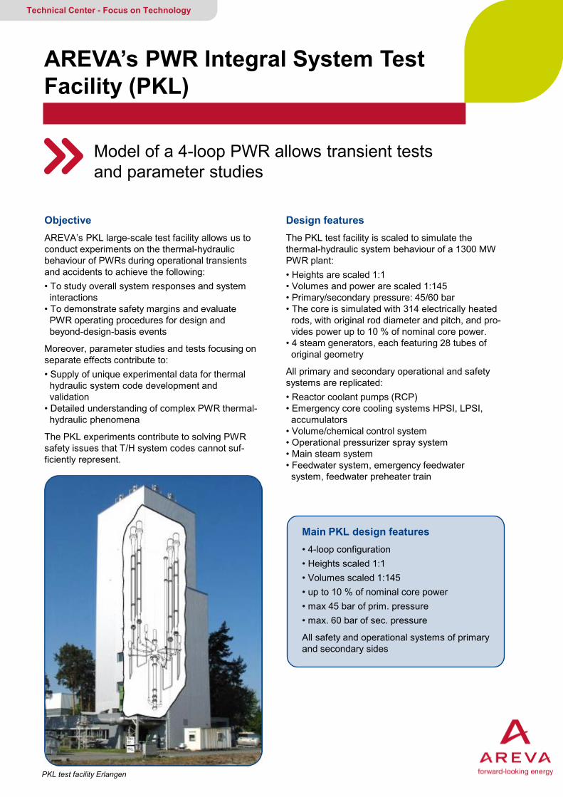
PKL test facility Erlangen
AREVA GMBH Your contact: [email protected]
AREVA’s PWR Integral System Test Facility (PKL) System Testing
Unique and approved test facility The PKL facility is extensively instrumented, (over 1500 measuring points) permitting a detailed depiction of the phenomena addressed by the tests. The facility is particularly suited for detailed analyses and interpretation of complex phenomena difficult to assess with T/H system codes.
More than 160 experiments covering a broad spectrum of scenarios have been addressed by PKL experiments since 1977, many with inter-national cooperation via the OECD: • Large break/small break LOCA • Steam generator tube rupture • Main steam line breaks • Station blackout, loss of feed water transients, bleed-and-feed procedures • Systematic studies, e.g., single-/two-phase natural circulation, reflux-condenser with/with- out non-condensable gases
Your benefits at a glance • Only 4-loop experimental test facility of its kind in the world models PWR integral system behaviour • Transient and accident analyses, procedure validation and separate effect tests contribute to solving PWR safety issues.
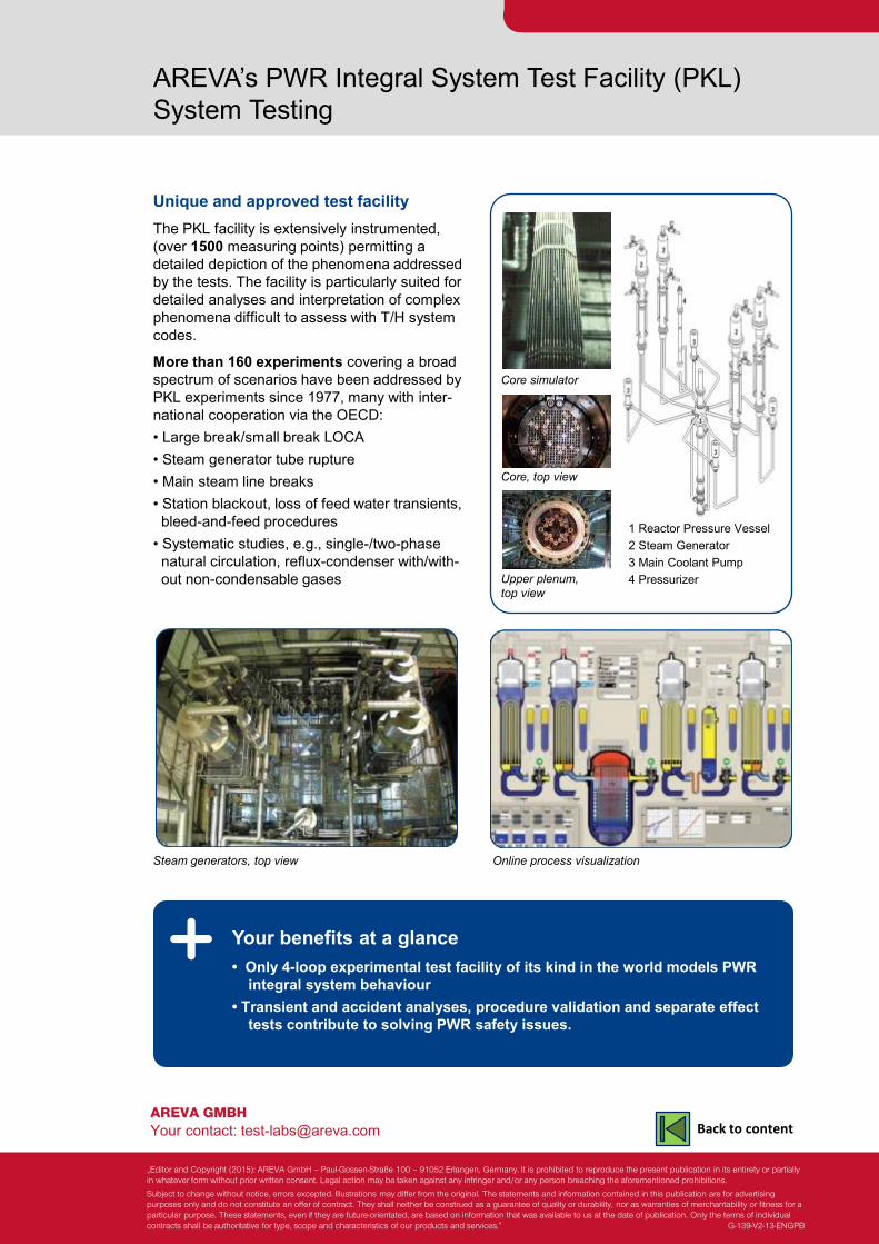
Steam generators, top view
1 Reactor Pressure Vessel 2 Steam Generator 3 Main Coolant Pump 4 Pressurizer
Core simulator
Core, top view
Upper plenum, top view
Online process visualization
„Editor and Copyright (2015): AREVA GmbH – Paul-Gossen-Straße 100 – 91052 Erlangen, Germany. It is prohibited to reproduce the present publication in its entirety or partially in whatever form without prior written consent. Legal action may be taken against any infringer and/or any person breaching the aforementioned prohibitions.
Subject to change without notice, errors excepted. Illustrations may differ from the original. The statements and information contained in this publication are for advertising purposes only and do not constitute an offer of contract. They shall neither be construed as a guarantee of quality or durability, nor as warranties of merchantability or fitness for a particular purpose. These statements, even if they are future-orientated, are based on information that was available to us at the date of publication. Only the terms of individual contracts shall be authoritative for type, scope and characteristics of our products and services.” G-139-V2-13-ENGPB
Back to content
Qualification & Services for Mechanical Components
As a nuclear service provider, AREVA provides a range of component qualification as well as maintenance services
Technical Center - Focus on Technology
For high power plant availability Our nuclear services contribute significantly: • Experimental qualification tests conducted in our laboratories verify the functional capability of components such as fuel assemblies, PWR control rod drive mechanisms (CRDMs) and valves. • Testing and diagnostic systems determine current component conditions during plant operation. Special-purpose measurements are also available if problems should arise. This facilitates condition-based maintenance and identification of measures to be taken.
• Component maintenance services, especially for valves and CRDMs, are provided either on a per-component basis or as an all-inclusive service package covering in-service inspection, maintenance, repair and adjustment of equipment settings. • Special-purpose measurements required in the event of functional problems are provided as an all-inclusive service package that starts with the initial planning and ends with a detailed analysis and evaluation of the measurement results.
Accreditation All services are performed to the high quality standards afforded by an accredited inspection body and testing laboratory.
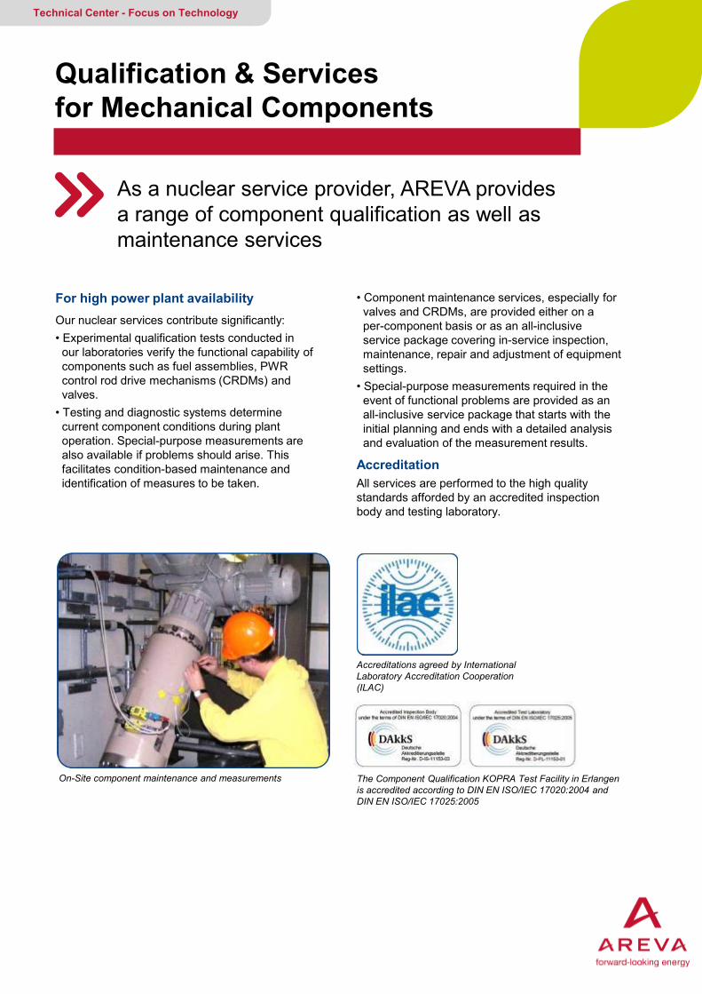
On-Site component maintenance and measurements
Accreditations agreed by International Laboratory Accreditation Cooperation (ILAC)
The Component Qualification KOPRA Test Facility in Erlangen is accredited according to DIN EN ISO/IEC 17020:2004 and DIN EN ISO/IEC 17025:2005

AREVA GMBH Your contact: [email protected]
Qualification & Services for Mechanical Components
Scope of our services • Planning service projects in close cooperation with customers and authorities. • Independent execution of projects either in the power plant or at our testing laboratories. • Processing and documentation of all results. • Consultation services • Processing regulatory requirements
Your benefits at a glance • Component qualification and testing in the laboratory • On-site component diagnostics and special measurements • Component maintenance • Manufacture of testing, measurement and diagnostic systems • Accredited test and inspection body • Accepted by ILAC
Laboratory facilities • Total floor space: 40 m x 25 m • Max. height: 28 m • Crane capacity: 100 t • Power supply: up to 1 MW • KOPRA Component Test Facility for PWR and BWR conditions • Consumables: compressed air, nitrogen, inert gases, demineralized water • Dose rate: 10-4 x limit for unrestricted release
Manufacture of testing, measuring and diagnostics systems
Component qualification testing in the laboratory
„Editor and Copyright (2015): AREVA GmbH – Paul-Gossen-Straße 100 – 91052 Erlangen, Germany. It is prohibited to reproduce the present publication in its entirety or partially in whatever form without prior written consent. Legal action may be taken against any infringer and/or any person breaching the aforementioned prohibitions.
Subject to change without notice, errors excepted. Illustrations may differ from the original. The statements and information contained in this publication are for advertising purposes only and do not constitute an offer of contract. They shall neither be construed as a guarantee of quality or durability, nor as warranties of merchantability or fitness for a particular purpose. These statements, even if they are future-orientated, are based on information that was available to us at the date of publication. Only the terms of individual contracts shall be authoritative for type, scope and characteristics of our products and services.” G-136-V3-13-ENGPB
Back to content
Full Scale Tests with KOPRA Component Test Facility for Qualification and Testing
Extensive experience in qualifying components under operational conditions
Technical Center - Focus on Technology
Component qualification Full-scale functional tests at appropriate temperature, pressure, and mass flow conditions are necessary for developing and qualifying nuclear components such as: - valves - safety valves - safety valve pilots - control rod drive mechanisms - fuel assemblies.
For endurance tests investigating long-term behaviour and wear effects, water chemistry must be adjusted to mimic that of reactor coolant conditions.
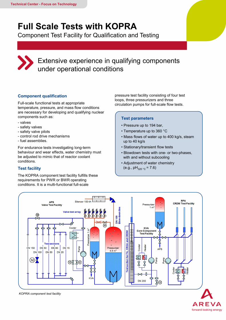
Test facility The KOPRA component test facility fulfills these requirements for PWR or BWR operating conditions. It is a multi-functional full-scale
Test parameters • Pressure up to 194 bar, • Temperature up to 360 °C • Mass flows of water up to 400 kg/s, steam up to 40 kg/s • Stationary/transient flow tests • Blowdown tests with one- or two-phases, with and without subcooling • Adjustment of water chemistry (e.g., pH320 °C = 7.6)
KOPRA component test facility
pressure test facility consisting of four test loops, three pressurizers and three circulation pumps for full-scale flow tests.
AREVA GMBH Your contact: [email protected]
AREVA‘s Component Test Facility KOPRA Qualification and Testing of Components at Full Scale
Further resources • Electrical and mechanical workshops manufac- ture standard products and special equipment. • Extensive infrastructure includes state-of-the- art measuring systems, various power supplies and control equipment.
Your benefits at a glance • Combination of powerful and flexible infrastructure and full-scale test facilities
• Integrated in AREVA’s thermal-hydraulic platform
• Accredited test and inspection body
• Accepted by ILAC
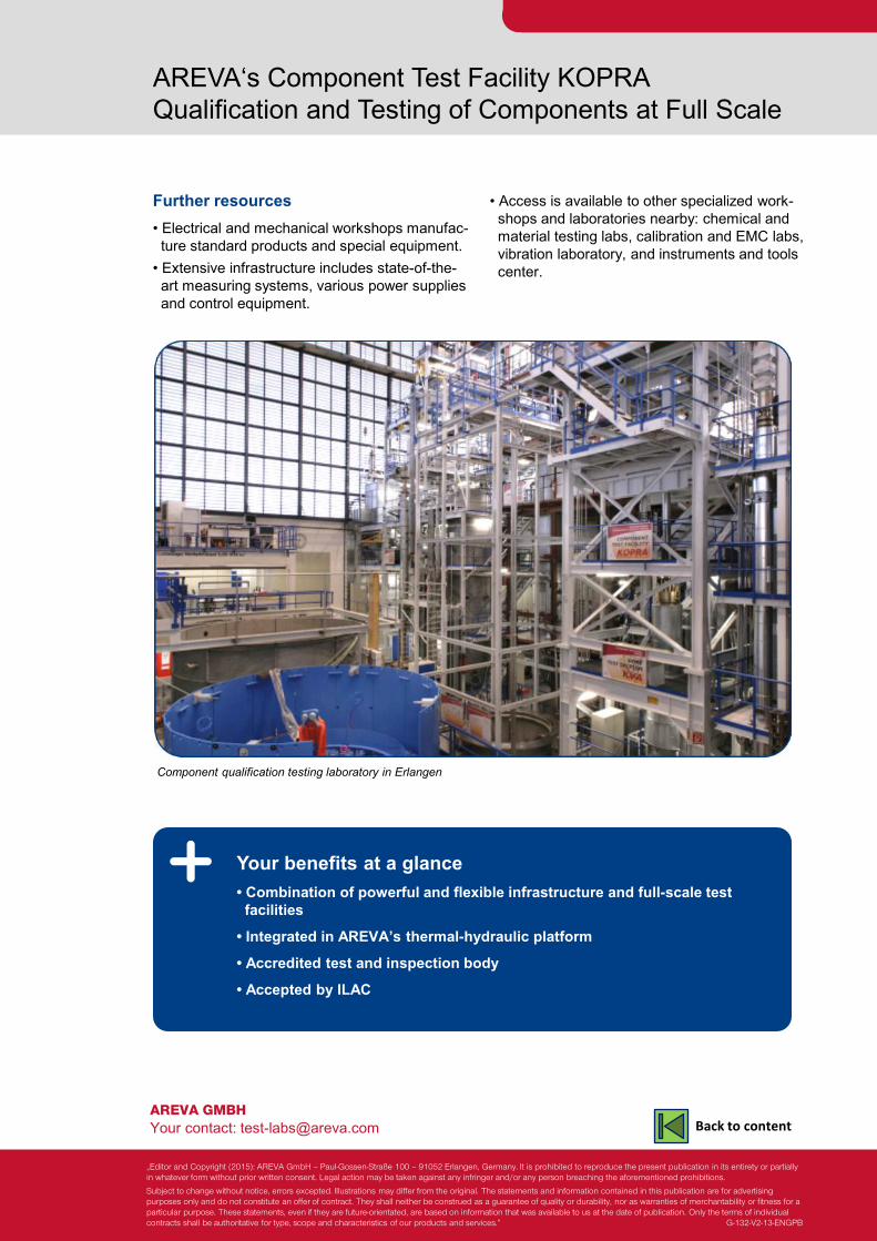
Component qualification testing laboratory in Erlangen
• Access is available to other specialized work- shops and laboratories nearby: chemical and material testing labs, calibration and EMC labs, vibration laboratory, and instruments and tools center.
„Editor and Copyright (2015): AREVA GmbH – Paul-Gossen-Straße 100 – 91052 Erlangen, Germany. It is prohibited to reproduce the present publication in its entirety or partially in whatever form without prior written consent. Legal action may be taken against any infringer and/or any person breaching the aforementioned prohibitions.
Subject to change without notice, errors excepted. Illustrations may differ from the original. The statements and information contained in this publication are for advertising purposes only and do not constitute an offer of contract. They shall neither be construed as a guarantee of quality or durability, nor as warranties of merchantability or fitness for a particular purpose. These statements, even if they are future-orientated, are based on information that was available to us at the date of publication. Only the terms of individual contracts shall be authoritative for type, scope and characteristics of our products and services.” G-132-V2-13-ENGPB
Back to content
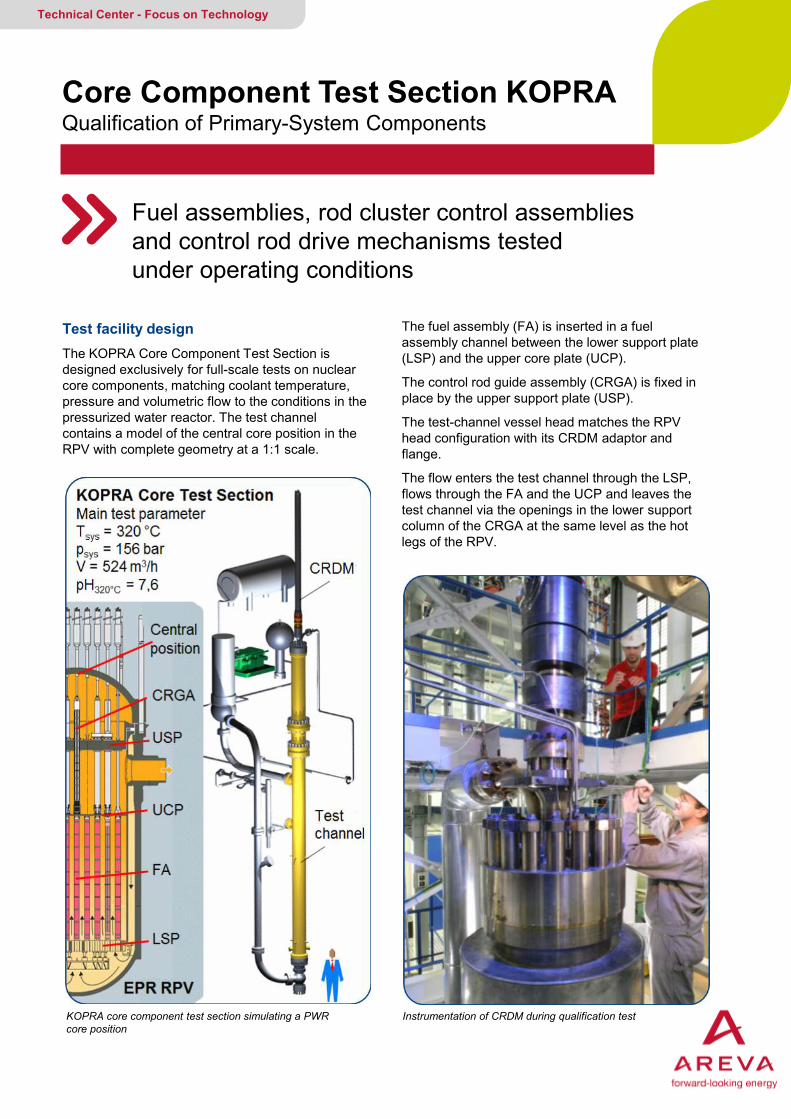
Core Component Test Section KOPRA Qualification of Primary-System Components
Fuel assemblies, rod cluster control assemblies and control rod drive mechanisms tested under operating conditions
Technical Center - Focus on Technology
Test facility design The KOPRA Core Component Test Section is designed exclusively for full-scale tests on nuclear core components, matching coolant temperature, pressure and volumetric flow to the conditions in the pressurized water reactor. The test channel contains a model of the central core position in the RPV with complete geometry at a 1:1 scale.
KOPRA core component test section simulating a PWR core position
The fuel assembly (FA) is inserted in a fuel assembly channel between the lower support plate (LSP) and the upper core plate (UCP).
The control rod guide assembly (CRGA) is fixed in place by the upper support plate (USP).
The test-channel vessel head matches the RPV head configuration with its CRDM adaptor and flange.
The flow enters the test channel through the LSP, flows through the FA and the UCP and leaves the test channel via the openings in the lower support column of the CRGA at the same level as the hot legs of the RPV.
Instrumentation of CRDM during qualification test

AREVA GMBH Your contact: [email protected]
Core Component Test Section KOPRA Qualification of Primary-System Components
Fuel assembly testing • Functional tests of entire fuel assembly with simulation of LSP, UCP, USP, CRGA and operational flow conditions.
• Investigations of fuel assembly and RCC-A behavior under normal and abnormal operating conditions.
• Fuel assembly pressure drop measurements under operation conditions and wear measurements.
• Endurance testing of flow-induced vibrations of fuel assemblies and fuel rods.
• Special investigations for new designs, e.g., RCC-A insertion tests, fuel assembly floating tests.
CRDM testing • Functional tests verify adequate performance, e.g., latch-unit armature closing and opening times, mobile set effective weight, drive rod loads during stepping operation, RCC-A drop times.
• Endurance tests to demonstrate that proper functioning can be reliably achieved over the specified number of CRDM steps and RCC-A drops with no damage.
• Special investigations for new designs, e.g., velocity and vibration measurements of drive rod during stepping operation.
Your benefits at a glance
• Designed for full-scale tests on nuclear core components at specific PWR flow, pressure and temperature conditions
• Flexible test section for component qualification, endurance testing and functional testing
• Accredited test and inspection body, accepted by ILAC
Test set-up CRDM qualification for EPRTM
„Editor and Copyright (2015): AREVA GmbH – Paul-Gossen-Straße 100 – 91052 Erlangen, Germany. It is prohibited to reproduce the present publication in its entirety or partially in whatever form without prior written consent. Legal action may be taken against any infringer and/or any person breaching the aforementioned prohibitions.
Subject to change without notice, errors excepted. Illustrations may differ from the original. The statements and information contained in this publication are for advertising purposes only and do not constitute an offer of contract. They shall neither be construed as a guarantee of quality or durability, nor as warranties of merchantability or fitness for a particular purpose. These statements, even if they are future-orientated, are based on information that was available to us at the date of publication. Only the terms of individual contracts shall be authoritative for type, scope and characteristics of our products and services.” G-136-V3-13-ENGPB
Back to content
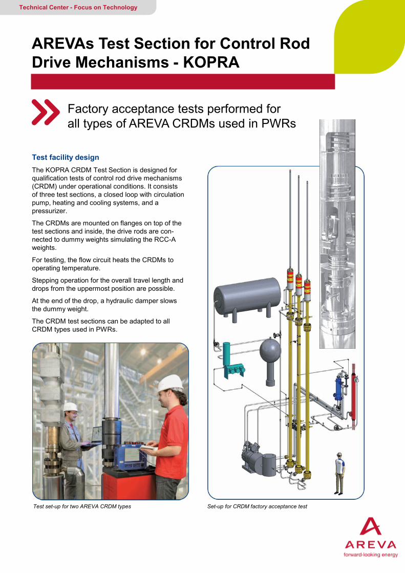
AREVAs Test Section for Control Rod Drive Mechanisms - KOPRA
Factory acceptance tests performed for all types of AREVA CRDMs used in PWRs
Technical Center - Focus on Technology
Test facility design The KOPRA CRDM Test Section is designed for qualification tests of control rod drive mechanisms (CRDM) under operational conditions. It consists of three test sections, a closed loop with circulation pump, heating and cooling systems, and a pressurizer.
The CRDMs are mounted on flanges on top of the test sections and inside, the drive rods are con-nected to dummy weights simulating the RCC-A weights.
For testing, the flow circuit heats the CRDMs to operating temperature.
Stepping operation for the overall travel length and drops from the uppermost position are possible.
At the end of the drop, a hydraulic damper slows the dummy weight.
The CRDM test sections can be adapted to all CRDM types used in PWRs.
Test set-up for two AREVA CRDM types Set-up for CRDM factory acceptance test

AREVA GMBH Your contact: [email protected]
AREVAs Test Section for Control Rod Drive Mechanisms - KOPRA
CRDM testing After manufacture and assembly, every CRDM must be qualified under operational conditions. The first functional test phase under operational conditions generates a magnetite layer on the sliding surfaces of the latch unit components, ensuring optimal antifriction properties. This is the basic requirement for dependable CRDM latch unit functionality.
The qualification test ensures the three operational functions of the CRDM:
• Insert and withdraw the mobile set (drive rod with coupled RCC-A dummy weight) in single steps to the required operating position.
Your benefits at a glance • CRDM test section designed for FAT under operational conditions
• Adaptation for all CRDM types used in PWRs
• Various CRDM control systems available
• Accredited test and inspection body, accepted by ILAC
• Hold the mobile set at any selected position along the travel length.
• Release the mobile set (for reactor trip).
In addition, qualification can be performed of the complete CRDM as part of special investigations for new designs, e.g., a rod position indicator system.
For CRDM operation, various generations of PWR rod control systems are available, (such as contactor control, ELSTABE, RodPilot® 10 and 40).
RodPilot® 10 cabinet Components of the CRDM
„Editor and Copyright (2015): AREVA GmbH – Paul-Gossen-Straße 100 – 91052 Erlangen, Germany. It is prohibited to reproduce the present publication in its entirety or partially in whatever form without prior written consent. Legal action may be taken against any infringer and/or any person breaching the aforementioned prohibitions.
Subject to change without notice, errors excepted. Illustrations may differ from the original. The statements and information contained in this publication are for advertising purposes only and do not constitute an offer of contract. They shall neither be construed as a guarantee of quality or durability, nor as warranties of merchantability or fitness for a particular purpose. These statements, even if they are future-orientated, are based on information that was available to us at the date of publication. Only the terms of individual contracts shall be authoritative for type, scope and characteristics of our products and services.” G-133-V2-13-ENGPB
Back to content
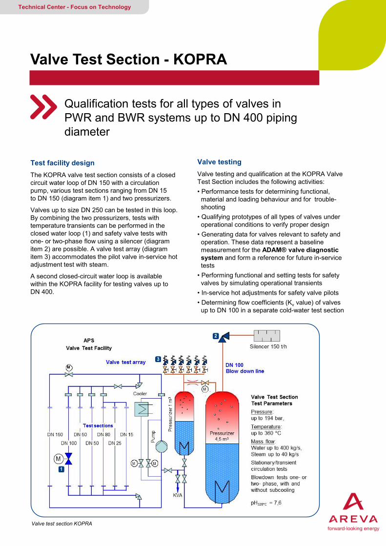
Valve Test Section - KOPRA
Qualification tests for all types of valves in PWR and BWR systems up to DN 400 piping diameter
Technical Center - Focus on Technology
Test facility design The KOPRA valve test section consists of a closed circuit water loop of DN 150 with a circulation pump, various test sections ranging from DN 15 to DN 150 (diagram item 1) and two pressurizers.
Valves up to size DN 250 can be tested in this loop. By combining the two pressurizers, tests with temperature transients can be performed in the closed water loop (1) and safety valve tests with one- or two-phase flow using a silencer (diagram item 2) are possible. A valve test array (diagram item 3) accommodates the pilot valve in-service hot adjustment test with steam.
A second closed-circuit water loop is available within the KOPRA facility for testing valves up to DN 400.
Valve testing Valve testing and qualification at the KOPRA Valve Test Section includes the following activities: • Performance tests for determining functional, material and loading behaviour and for trouble- shooting • Qualifying prototypes of all types of valves under operational conditions to verify proper design • Generating data for valves relevant to safety and operation. These data represent a baseline measurement for the ADAM® valve diagnostic system and form a reference for future in-service tests • Performing functional and setting tests for safety valves by simulating operational transients • In-service hot adjustments for safety valve pilots • Determining flow coefficients (Kv value) of valves up to DN 100 in a separate cold-water test section
Valve test section KOPRA
AREVA GMBH Your contact: [email protected]
Valve Test Section - KOPRA
Your benefits at a glance • Testing under operational conditions • Water flow up to 400 kg/s, steam flow up to 40 kg/s • Stationary/transient circulation tests • Blowdown tests with one- or two-phases, with and without subcooling • Accredited test and inspection body, accepted by ILAC
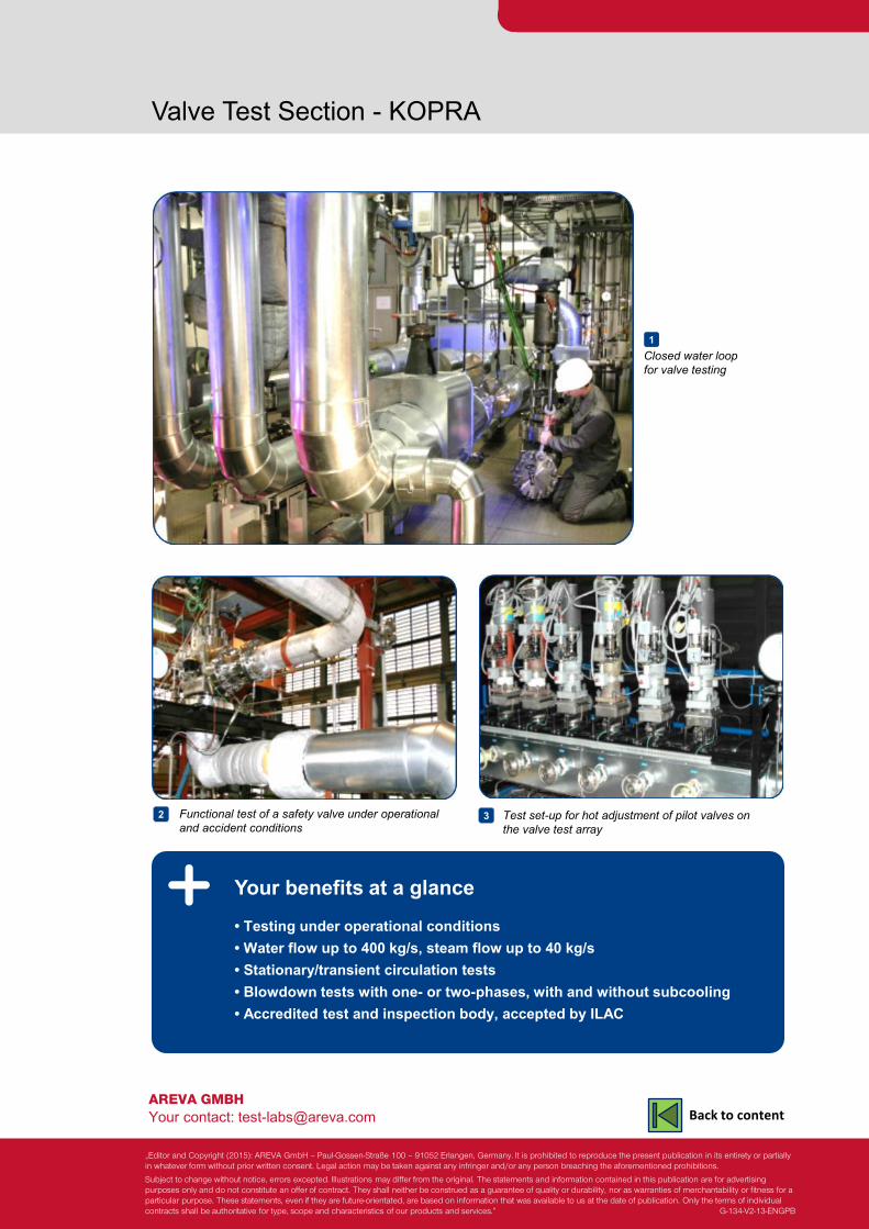
Closed water loop for valve testing
Test set-up for hot adjustment of pilot valves on the valve test array
3 Functional test of a safety valve under operational and accident conditions
2
1
„Editor and Copyright (2015): AREVA GmbH – Paul-Gossen-Straße 100 – 91052 Erlangen, Germany. It is prohibited to reproduce the present publication in its entirety or partially in whatever form without prior written consent. Legal action may be taken against any infringer and/or any person breaching the aforementioned prohibitions.
Subject to change without notice, errors excepted. Illustrations may differ from the original. The statements and information contained in this publication are for advertising purposes only and do not constitute an offer of contract. They shall neither be construed as a guarantee of quality or durability, nor as warranties of merchantability or fitness for a particular purpose. These statements, even if they are future-orientated, are based on information that was available to us at the date of publication. Only the terms of individual contracts shall be authoritative for type, scope and characteristics of our products and services.” G-134-V2-13-ENGPB
Back to content
Special Valve Analysis & Testing KOPRA
Facility qualifies and functionally tests valves with diameters ≥ DN 200 under simulated operating conditions
Technical Center - Focus on Technology
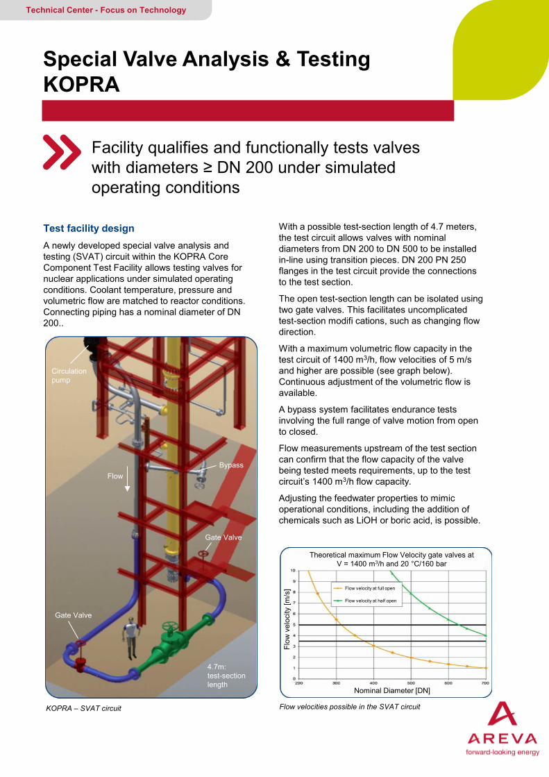
Test facility design A newly developed special valve analysis and testing (SVAT) circuit within the KOPRA Core Component Test Facility allows testing valves for nuclear applications under simulated operating conditions. Coolant temperature, pressure and volumetric flow are matched to reactor conditions. Connecting piping has a nominal diameter of DN 200..
KOPRA – SVAT circuit
With a possible test-section length of 4.7 meters, the test circuit allows valves with nominal diameters from DN 200 to DN 500 to be installed in-line using transition pieces. DN 200 PN 250 flanges in the test circuit provide the connections to the test section.
The open test-section length can be isolated using two gate valves. This facilitates uncomplicated test-section modifi cations, such as changing flow direction.
With a maximum volumetric flow capacity in the test circuit of 1400 m3/h, flow velocities of 5 m/s and higher are possible (see graph below). Continuous adjustment of the volumetric flow is available.
A bypass system facilitates endurance tests involving the full range of valve motion from open to closed.
Flow measurements upstream of the test section can confirm that the flow capacity of the valve being tested meets requirements, up to the test circuit’s 1400 m3/h flow capacity.
Adjusting the feedwater properties to mimic operational conditions, including the addition of chemicals such as LiOH or boric acid, is possible.
Flow velocities possible in the SVAT circuit
4.7m: test-section length
Gate Valve
Gate Valve
Bypass Flow
Circulation pump
Theoretical maximum Flow Velocity gate valves at V = 1400 m3/h and 20 °C/160 bar
Flow velocity at full open
Flow velocity at half open
Flow
vel
ocity
[m/s
]
Nominal Diameter [DN]
AREVA GMBH Your contact: [email protected]
Special Valve Analysis & Testing KOPRA
Valve testing • Functional testing of valves at simulated operational flow conditions
• Endurance testing of valves under operational conditions
Your benefits at a glance
• Tests of nuclear components under full-scale temperature and pressure conditions at high volumetric flow
• Flexible test circuit for valve qualification, endurance and functional testing
• Accredited test and inspection body, accepted by ILAC and open to external costumers
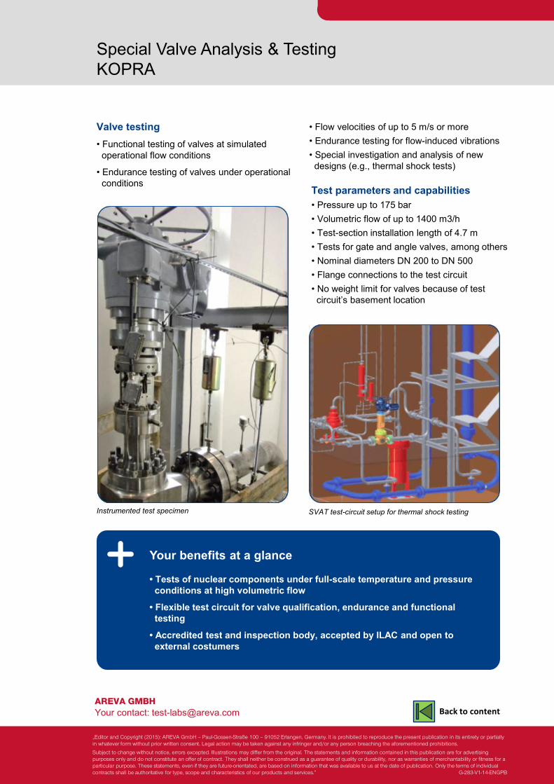
Instrumented test specimen
• Flow velocities of up to 5 m/s or more • Endurance testing for flow-induced vibrations • Special investigation and analysis of new designs (e.g., thermal shock tests)
Test parameters and capabilities • Pressure up to 175 bar • Volumetric flow of up to 1400 m3/h • Test-section installation length of 4.7 m • Tests for gate and angle valves, among others • Nominal diameters DN 200 to DN 500 • Flange connections to the test circuit • No weight limit for valves because of test circuit’s basement location
SVAT test-circuit setup for thermal shock testing
„Editor and Copyright (2015): AREVA GmbH – Paul-Gossen-Straße 100 – 91052 Erlangen, Germany. It is prohibited to reproduce the present publication in its entirety or partially in whatever form without prior written consent. Legal action may be taken against any infringer and/or any person breaching the aforementioned prohibitions.
Subject to change without notice, errors excepted. Illustrations may differ from the original. The statements and information contained in this publication are for advertising purposes only and do not constitute an offer of contract. They shall neither be construed as a guarantee of quality or durability, nor as warranties of merchantability or fitness for a particular purpose. These statements, even if they are future-orientated, are based on information that was available to us at the date of publication. Only the terms of individual contracts shall be authoritative for type, scope and characteristics of our products and services.” G-283-V1-14-ENGPB
Back to content
Critical Heat Flux (CHF) Tests with AREVAs KATHY Loop
CHF tests are essential for licensing nuclear fuel. The KATHY-Loop is designed to determine the CHF under large-scale. The KATHY Loop determines CHF under large scale conditions with electrically heated fuel assembly models
Technical Center - Focus on Technology
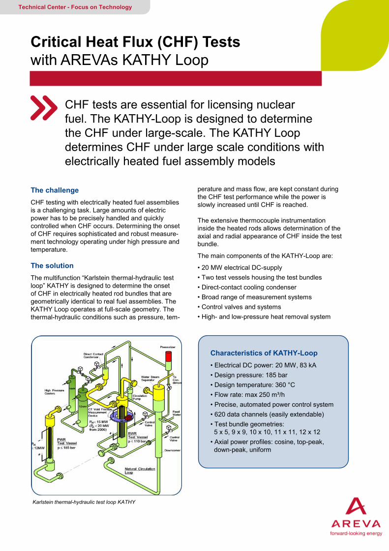
The challenge CHF testing with electrically heated fuel assemblies is a challenging task. Large amounts of electric power has to be precisely handled and quickly controlled when CHF occurs. Determining the onset of CHF requires sophisticated and robust measure-ment technology operating under high pressure and temperature. The solution The multifunction “Karlstein thermal-hydraulic test loop” KATHY is designed to determine the onset of CHF in electrically heated rod bundles that are geometrically identical to real fuel assemblies. The KATHY Loop operates at full-scale geometry. The thermal-hydraulic conditions such as pressure, tem-
Karlstein thermal-hydraulic test loop KATHY
perature and mass flow, are kept constant during the CHF test performance while the power is slowly increased until CHF is reached. The extensive thermocouple instrumentation inside the heated rods allows determination of the axial and radial appearance of CHF inside the test bundle.
The main components of the KATHY-Loop are:
• 20 MW electrical DC-supply • Two test vessels housing the test bundles • Direct-contact cooling condenser • Broad range of measurement systems • Control valves and systems • High- and low-pressure heat removal system
Characteristics of KATHY-Loop • Electrical DC power: 20 MW, 83 kA • Design pressure: 185 bar • Design temperature: 360 °C • Flow rate: max 250 m³/h • Precise, automated power control system • 620 data channels (easily extendable) • Test bundle geometries: 5 x 5, 9 x 9, 10 x 10, 11 x 11, 12 x 12 • Axial power profiles: cosine, top-peak, down-peak, uniform

AREVA GMBH Your contact: [email protected]
Qualification of Components KATHY Loop for Critical Heat Flux (CHF) Tests
Versatile and multifunctional test loop performs • CHF tests on full-scale BWR test bundles • CHF tests on 5x5 PWR test bundles
Your benefits at a glance • State-of-the-art test loop • More than 2,500 heater rods in stock • Duration of each test step: 5-10 min. • Benchmarked against OMEGA-Loop (CEA), ATLAS-Loop (GE) and HTRF- Loop (CU) • Integration with and access to AREVA’s thermal-hydraulic platform • Accredited test and inspection body • Accepted by ILAC
Installation of a test bundle
• Single-phase pressure drop measurements • Adiabatic two-phase flow pressure drop measurements. • Void fraction measurement with gamma ray densitometer • Simulation of reactor transients (e.g., pump trip, turbine trip) • Hydraulic stability investigations on BWR test bundles under natural circulation conditions • In operation since 1986 with more than 30,000 test runs.
A test bundle has the same geometry as a fuel assembly
Experienced in CHF since 1986 and well equipped for the future.
„Editor and Copyright (2015): AREVA GmbH – Paul-Gossen-Straße 100 – 91052 Erlangen, Germany. It is prohibited to reproduce the present publication in its entirety or partially in whatever form without prior written consent. Legal action may be taken against any infringer and/or any person breaching the aforementioned prohibitions.
Subject to change without notice, errors excepted. Illustrations may differ from the original. The statements and information contained in this publication are for advertising purposes only and do not constitute an offer of contract. They shall neither be construed as a guarantee of quality or durability, nor as warranties of merchantability or fitness for a particular purpose. These statements, even if they are future-orientated, are based on information that was available to us at the date of publication. Only the terms of individual contracts shall be authoritative for type, scope and characteristics of our products and services.” G-112-V3-13-ENGPB
Back to content
PWR Fuel Element Tests at Erlangen PETER
Full scale thermal-hydraulic facility tests PWR fuel assemblies for FA vibration and bowing behavior under various geometric and flow boundary conditions
Technical Center - Focus on Technology
The challenge Reliable and safe FA operation at maximum performance promotes optimal NPP operation. This must be ensured for a wide variety of FA designs in combination with a number of different plant designs.
The solution Operating a test facility with maximum flexibility in geometric and flow boundary conditions.
Experimental investigations of PWR fuel assemblies enhance nuclear power plant safety and reliability.
Optimizing fluid-dynamics performance leads to new developments in fuel assembly design and helps improve plant economics, for example:
• Better coolant mixing enables achievement of higher power levels and higher burn-ups, improving economic efficiency
• The in-core reliability of AREVA fuel assemblies can be enhanced even further
• Fuel assembly costs can be optimized
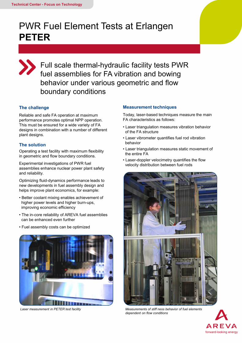
Laser measurement in PETER test facility
Measurement techniques Today, laser-based techniques measure the main FA characteristics as follows:
• Laser triangulation measures vibration behavior of the FA structure • Laser vibrometer quantifies fuel rod vibration behavior • Laser triangulation measures static movement of the entire FA • Laser-doppler velocimetry quantifies the flow velocity distribution between fuel rods
Measurements of stiff ness behavior of fuel elements dependent on flow conditions
AREVA GMBH Your contact: [email protected]
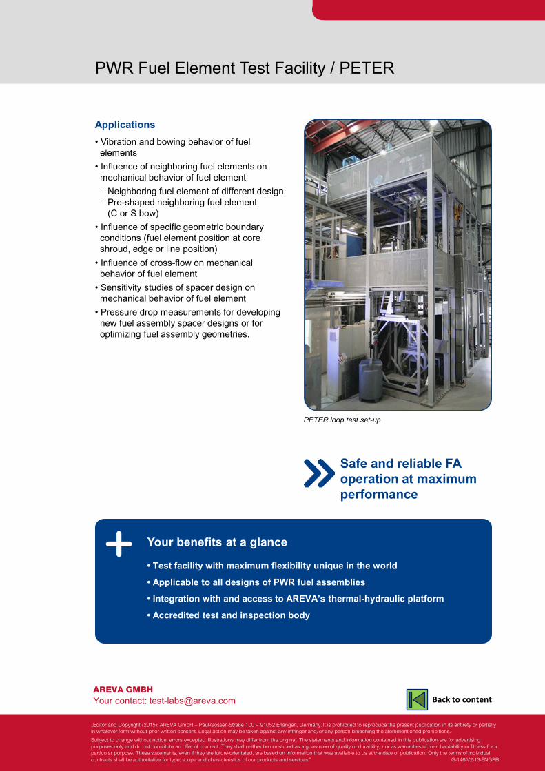
PWR Fuel Element Test Facility / PETER
Applications • Vibration and bowing behavior of fuel elements • Influence of neighboring fuel elements on mechanical behavior of fuel element – Neighboring fuel element of different design – Pre-shaped neighboring fuel element (C or S bow) • Influence of specific geometric boundary conditions (fuel element position at core shroud, edge or line position) • Influence of cross-flow on mechanical behavior of fuel element • Sensitivity studies of spacer design on mechanical behavior of fuel element • Pressure drop measurements for developing new fuel assembly spacer designs or for optimizing fuel assembly geometries.
Your benefits at a glance
• Test facility with maximum flexibility unique in the world
• Applicable to all designs of PWR fuel assemblies
• Integration with and access to AREVA’s thermal-hydraulic platform
• Accredited test and inspection body
PETER loop test set-up
Safe and reliable FA operation at maximum performance
„Editor and Copyright (2015): AREVA GmbH – Paul-Gossen-Straße 100 – 91052 Erlangen, Germany. It is prohibited to reproduce the present publication in its entirety or partially in whatever form without prior written consent. Legal action may be taken against any infringer and/or any person breaching the aforementioned prohibitions.
Subject to change without notice, errors excepted. Illustrations may differ from the original. The statements and information contained in this publication are for advertising purposes only and do not constitute an offer of contract. They shall neither be construed as a guarantee of quality or durability, nor as warranties of merchantability or fitness for a particular purpose. These statements, even if they are future-orientated, are based on information that was available to us at the date of publication. Only the terms of individual contracts shall be authoritative for type, scope and characteristics of our products and services.” G-146-V2-13-ENGPB
Back to content
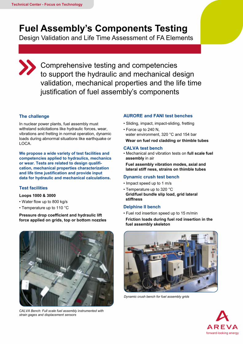
The challenge In nuclear power plants, fuel assembly must withstand solicitations like hydraulic forces, wear, vibrations and fretting in normal operation, dynamic loads during abnormal situations like earthquake or LOCA. We propose a wide variety of test facilities and competencies applied to hydraulics, mechanics or wear. Tests are related to design qualifi-cation, mechanical properties characterization and life time justification and provide input data for hydraulic and mechanical calculations. Test facilities Loops 1000 & 3000 • Water flow up to 800 kg/s • Temperature up to 110 °C
Pressure drop coefficient and hydraulic lift force applied on grids, top or bottom nozzles
Fuel Assembly’s Components Testing Design Validation and Life Time Assessment of FA Elements
Comprehensive testing and competencies to support the hydraulic and mechanical design validation, mechanical properties and the life time justification of fuel assembly’s components
Technical Center - Focus on Technology
AURORE and FANI test benches • Sliding, impact, impact-sliding, fretting • Force up to 240 N, water environment, 320 °C and 154 bar Wear on fuel rod cladding or thimble tubes
CALVA test bench • Mechanical and vibration tests on full scale fuel assembly in air Fuel assembly vibration modes, axial and lateral stiff ness, strains on thimble tubes
Dynamic crush test bench • Impact speed up to 1 m/s • Temperature up to 320 °C Grid/fuel bundle slip load, grid lateral stiffness
Delphine II bench • Fuel rod insertion speed up to 15 m/min Friction loads during fuel rod insertion in the fuel assembly skeleton
CALVA Bench: Full scale fuel assembly instrumented with strain gages and displacement sensors
Dynamic crush bench for fuel assembly grids
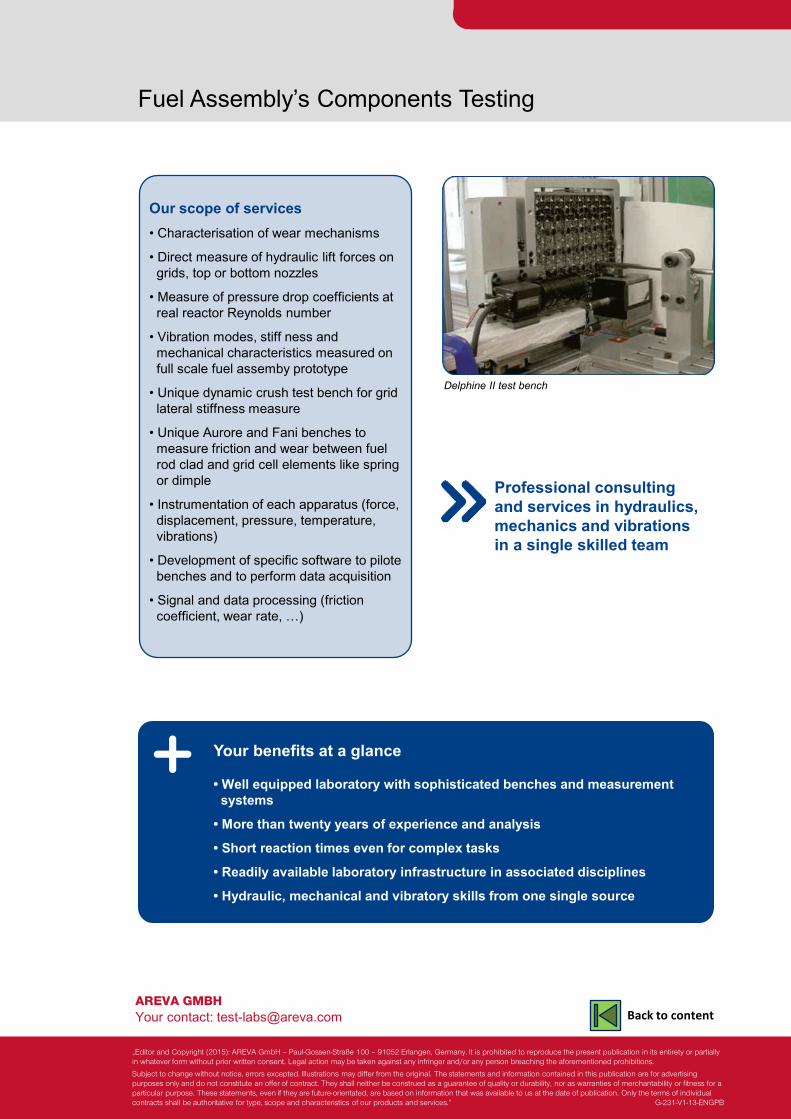
AREVA GMBH Your contact: [email protected]
Fuel Assembly’s Components Testing
Our scope of services • Characterisation of wear mechanisms
• Direct measure of hydraulic lift forces on grids, top or bottom nozzles
• Measure of pressure drop coefficients at real reactor Reynolds number
• Vibration modes, stiff ness and mechanical characteristics measured on full scale fuel assemby prototype
• Unique dynamic crush test bench for grid lateral stiffness measure
• Unique Aurore and Fani benches to measure friction and wear between fuel rod clad and grid cell elements like spring or dimple
• Instrumentation of each apparatus (force, displacement, pressure, temperature, vibrations)
• Development of specific software to pilote benches and to perform data acquisition
• Signal and data processing (friction coefficient, wear rate, …)
Your benefits at a glance
• Well equipped laboratory with sophisticated benches and measurement systems
• More than twenty years of experience and analysis
• Short reaction times even for complex tasks
• Readily available laboratory infrastructure in associated disciplines
• Hydraulic, mechanical and vibratory skills from one single source
Delphine II test bench
Professional consulting and services in hydraulics, mechanics and vibrations in a single skilled team
„Editor and Copyright (2015): AREVA GmbH – Paul-Gossen-Straße 100 – 91052 Erlangen, Germany. It is prohibited to reproduce the present publication in its entirety or partially in whatever form without prior written consent. Legal action may be taken against any infringer and/or any person breaching the aforementioned prohibitions.
Subject to change without notice, errors excepted. Illustrations may differ from the original. The statements and information contained in this publication are for advertising purposes only and do not constitute an offer of contract. They shall neither be construed as a guarantee of quality or durability, nor as warranties of merchantability or fitness for a particular purpose. These statements, even if they are future-orientated, are based on information that was available to us at the date of publication. Only the terms of individual contracts shall be authoritative for type, scope and characteristics of our products and services.” G-231-V1-13-ENGPB
Back to content
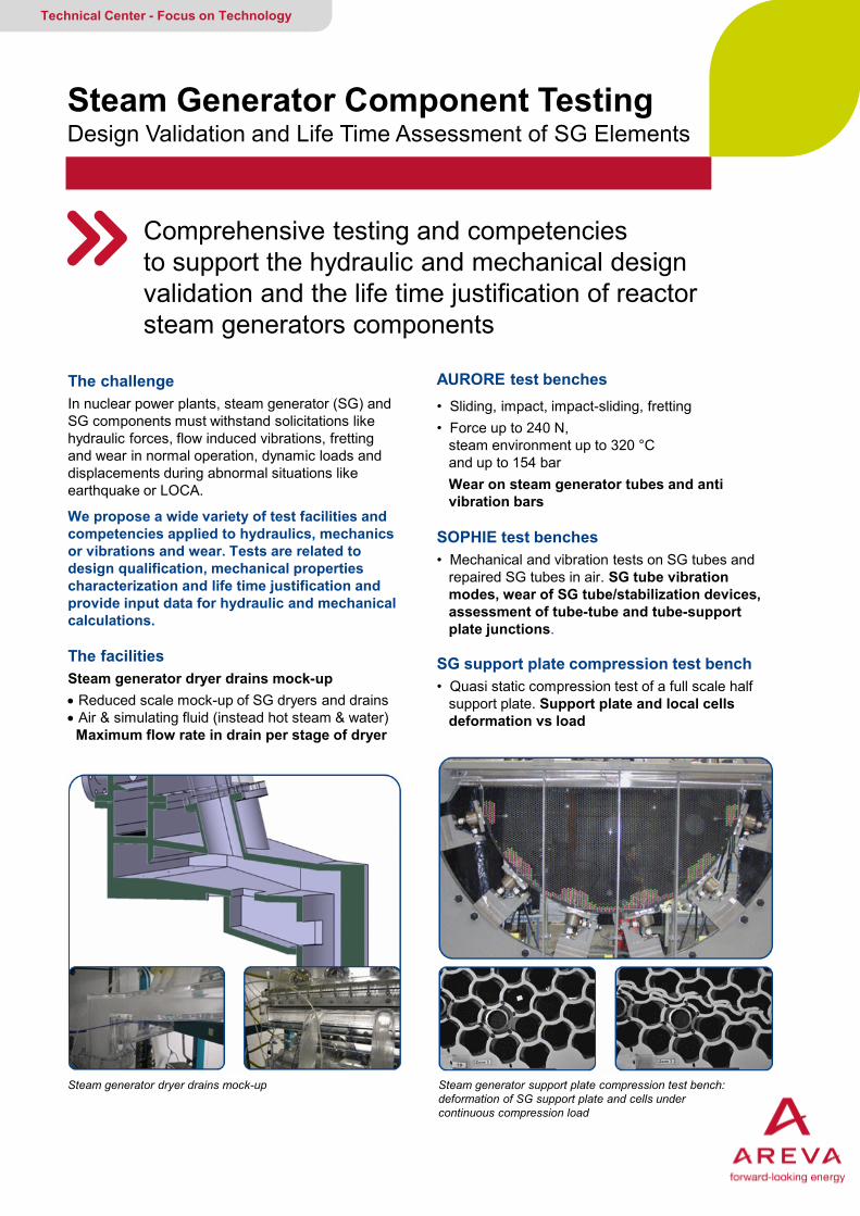
The challenge In nuclear power plants, steam generator (SG) and SG components must withstand solicitations like hydraulic forces, flow induced vibrations, fretting and wear in normal operation, dynamic loads and displacements during abnormal situations like earthquake or LOCA.
We propose a wide variety of test facilities and competencies applied to hydraulics, mechanics or vibrations and wear. Tests are related to design qualification, mechanical properties characterization and life time justification and provide input data for hydraulic and mechanical calculations.
The facilities Steam generator dryer drains mock-up • Reduced scale mock-up of SG dryers and drains • Air & simulating fluid (instead hot steam & water) Maximum flow rate in drain per stage of dryer
Steam Generator Component Testing Design Validation and Life Time Assessment of SG Elements
Comprehensive testing and competencies to support the hydraulic and mechanical design validation and the life time justification of reactor steam generators components
Technical Center - Focus on Technology
AURORE test benches • Sliding, impact, impact-sliding, fretting • Force up to 240 N, steam environment up to 320 °C and up to 154 bar Wear on steam generator tubes and anti vibration bars
Steam generator dryer drains mock-up Steam generator support plate compression test bench: deformation of SG support plate and cells under continuous compression load
SOPHIE test benches • Mechanical and vibration tests on SG tubes and repaired SG tubes in air. SG tube vibration modes, wear of SG tube/stabilization devices, assessment of tube-tube and tube-support plate junctions.
SG support plate compression test bench • Quasi static compression test of a full scale half support plate. Support plate and local cells deformation vs load

AREVA GMBH Your contact: [email protected]
Reactor Steam Generator Component Testing
Our scope of services • Characterisation of wear mechanisms,
• Unique skills and knowledge to design, manufacture and operate test facilities in hydraulics and mechanics
• Vibration modes and mechanical characteristics measured on full scale SG tubes
• Unique Aurore to measure wear between SG tube and Anti Vibration Bar
• Instrumentation of each apparatus (force, displacement, pressure, temperature, vibrations)
• Development of specific software to pilote benches and to perform data acquisition
• Signal and data processing (friction coefficient, wear rate,…)
Your benefits at a glance
• Well equipped laboratory with sophisticated benches and measurement systems
• More than twenty years of experience and analysis
• Short reaction times even for complex tasks
• Readily available laboratory infrastructure in associated disciplines
• Hydraulic, mechanical and vibratory skills from one single source
Sophie test bench: vibrations of steam generator tubes
Professional consulting and services in hydraulics, mechanics and vibrations in a single skilled team
„Editor and Copyright (2015): AREVA GmbH – Paul-Gossen-Straße 100 – 91052 Erlangen, Germany. It is prohibited to reproduce the present publication in its entirety or partially in whatever form without prior written consent. Legal action may be taken against any infringer and/or any person breaching the aforementioned prohibitions.
Subject to change without notice, errors excepted. Illustrations may differ from the original. The statements and information contained in this publication are for advertising purposes only and do not constitute an offer of contract. They shall neither be construed as a guarantee of quality or durability, nor as warranties of merchantability or fitness for a particular purpose. These statements, even if they are future-orientated, are based on information that was available to us at the date of publication. Only the terms of individual contracts shall be authoritative for type, scope and characteristics of our products and services.”
Back to content
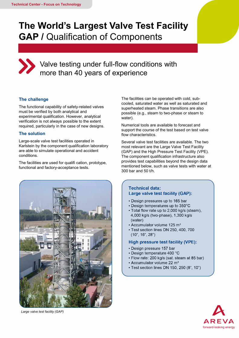
The challenge The functional capability of safety-related valves must be verified by both analytical and experimental qualification. However, analytical verification is not always possible to the extent required, particularly in the case of new designs.
The solution Large-scale valve test facilities operated in Karlstein by the component qualification laboratory are able to simulate operational and accident conditions.
The facilities are used for qualifi cation, prototype, functional and factory-acceptance tests.
The World’s Largest Valve Test Facility GAP / Qualification of Components
Valve testing under full-flow conditions with more than 40 years of experience
Technical Center - Focus on Technology
The facilities can be operated with cold, sub-cooled, saturated water as well as saturated and superheated steam. Phase transitions are also possible (e.g., steam to two-phase or steam to water).
Numerical tools are available to forecast and support the course of the test based on test valve flow characteristics.
Several valve test facilities are available. The two most relevant are the Large Valve Test Facility (GAP) and the High Pressure Test Facility (VPE). The component qualification infrastructure also provides test capabilities beyond the design data mentioned below, such as valve tests with water at 300 bar and 50 t/h.
Large valve test facility (GAP)
Technical data: Large valve test facility (GAP): • Design pressures up to 165 bar • Design temperatures up to 350°C • Total flow rate up to 2,000 kg/s (steam), 4,000 kg/s (two-phase), 1,300 kg/s (water) • Accumulator volume 125 m³ • Test section lines DN 250, 400, 700 (10”, 16”, 28”)
High pressure test facility (VPE): • Design pressure 157 bar • Design temperature 400 °C • Flow rate: 200 kg/s (sat. steam at 85 bar) • Accumulator volume 22 m³ • Test section lines DN 150, 250 (8”, 10”)
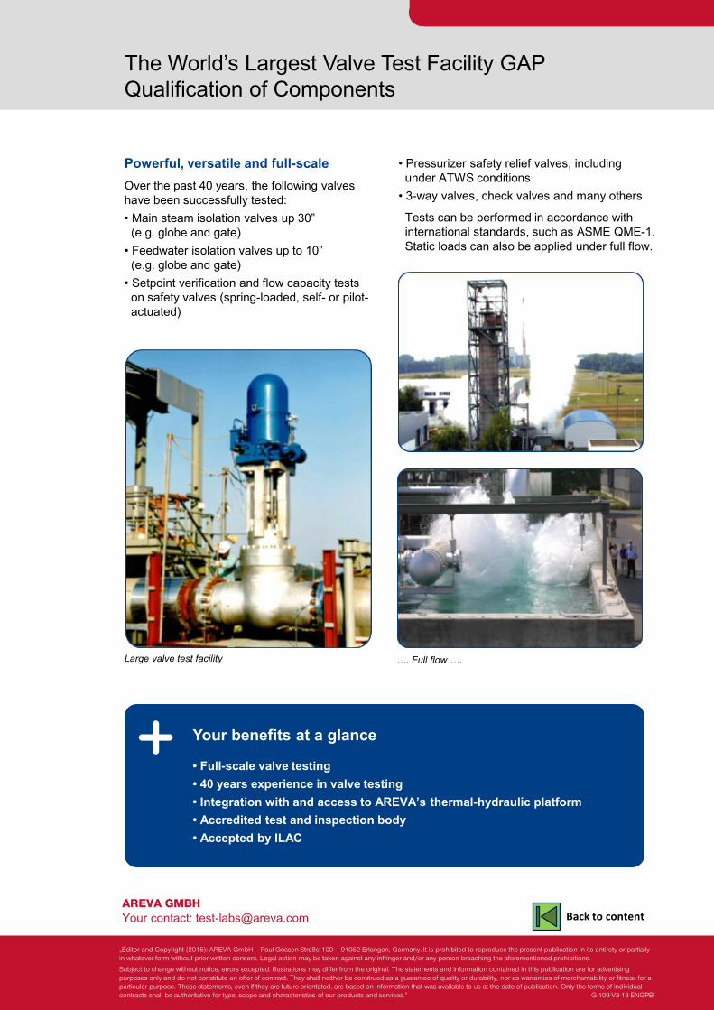
AREVA GMBH Your contact: [email protected]
The World’s Largest Valve Test Facility GAP Qualification of Components
Powerful, versatile and full-scale Over the past 40 years, the following valves have been successfully tested: • Main steam isolation valves up 30” (e.g. globe and gate) • Feedwater isolation valves up to 10” (e.g. globe and gate) • Setpoint verification and flow capacity tests on safety valves (spring-loaded, self- or pilot- actuated)
Your benefits at a glance • Full-scale valve testing • 40 years experience in valve testing • Integration with and access to AREVA’s thermal-hydraulic platform • Accredited test and inspection body • Accepted by ILAC
Large valve test facility
• Pressurizer safety relief valves, including under ATWS conditions • 3-way valves, check valves and many others
Tests can be performed in accordance with international standards, such as ASME QME-1. Static loads can also be applied under full flow.
…. Full flow ….
„Editor and Copyright (2015): AREVA GmbH – Paul-Gossen-Straße 100 – 91052 Erlangen, Germany. It is prohibited to reproduce the present publication in its entirety or partially in whatever form without prior written consent. Legal action may be taken against any infringer and/or any person breaching the aforementioned prohibitions.
Subject to change without notice, errors excepted. Illustrations may differ from the original. The statements and information contained in this publication are for advertising purposes only and do not constitute an offer of contract. They shall neither be construed as a guarantee of quality or durability, nor as warranties of merchantability or fitness for a particular purpose. These statements, even if they are future-orientated, are based on information that was available to us at the date of publication. Only the terms of individual contracts shall be authoritative for type, scope and characteristics of our products and services.” G-109-V3-13-ENGPB
Back to content
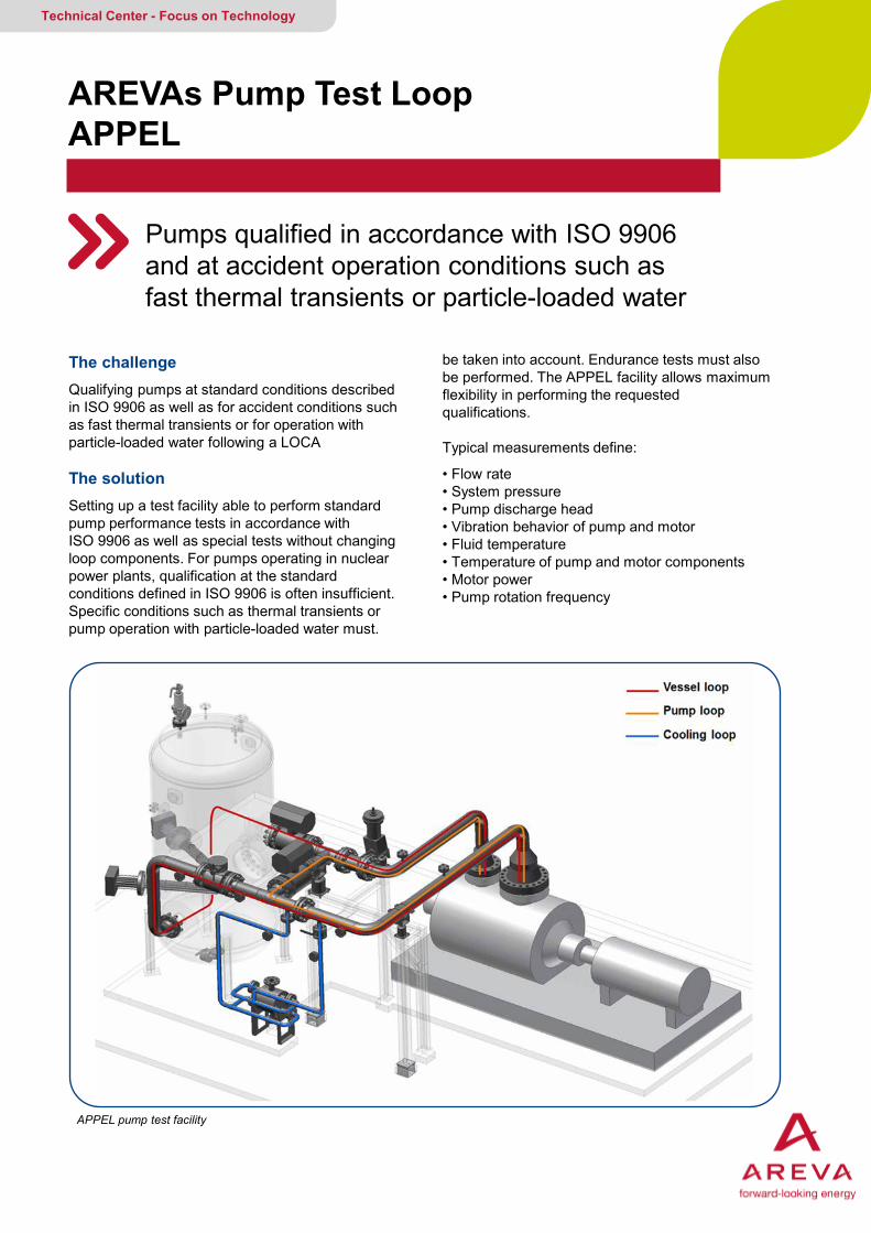
The challenge Qualifying pumps at standard conditions described in ISO 9906 as well as for accident conditions such as fast thermal transients or for operation with particle-loaded water following a LOCA The solution Setting up a test facility able to perform standard pump performance tests in accordance with ISO 9906 as well as special tests without changing loop components. For pumps operating in nuclear power plants, qualification at the standard conditions defined in ISO 9906 is often insufficient. Specific conditions such as thermal transients or pump operation with particle-loaded water must.
AREVAs Pump Test Loop APPEL
Pumps qualified in accordance with ISO 9906 and at accident operation conditions such as fast thermal transients or particle-loaded water
Technical Center - Focus on Technology
be taken into account. Endurance tests must also be performed. The APPEL facility allows maximum flexibility in performing the requested qualifications. Typical measurements define:
• Flow rate • System pressure • Pump discharge head • Vibration behavior of pump and motor • Fluid temperature • Temperature of pump and motor components • Motor power • Pump rotation frequency
APPEL pump test facility
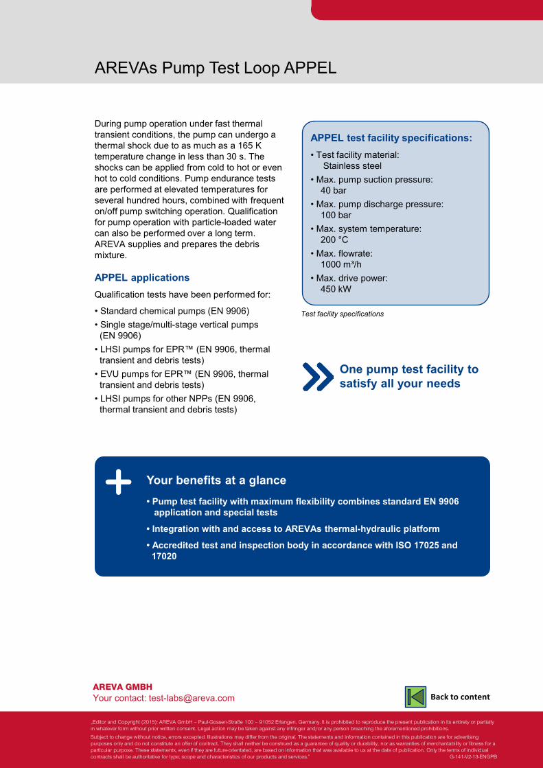
AREVA GMBH Your contact: [email protected]
AREVAs Pump Test Loop APPEL
During pump operation under fast thermal transient conditions, the pump can undergo a thermal shock due to as much as a 165 K temperature change in less than 30 s. The shocks can be applied from cold to hot or even hot to cold conditions. Pump endurance tests are performed at elevated temperatures for several hundred hours, combined with frequent on/off pump switching operation. Qualification for pump operation with particle-loaded water can also be performed over a long term. AREVA supplies and prepares the debris mixture. APPEL applications Qualification tests have been performed for:
• Standard chemical pumps (EN 9906) • Single stage/multi-stage vertical pumps (EN 9906) • LHSI pumps for EPR™ (EN 9906, thermal transient and debris tests) • EVU pumps for EPR™ (EN 9906, thermal transient and debris tests) • LHSI pumps for other NPPs (EN 9906, thermal transient and debris tests)
Your benefits at a glance • Pump test facility with maximum flexibility combines standard EN 9906 application and special tests
• Integration with and access to AREVAs thermal-hydraulic platform
• Accredited test and inspection body in accordance with ISO 17025 and 17020
APPEL test facility specifications: • Test facility material: Stainless steel • Max. pump suction pressure: 40 bar • Max. pump discharge pressure: 100 bar • Max. system temperature: 200 °C • Max. flowrate: 1000 m³/h • Max. drive power: 450 kW
Test facility specifications
One pump test facility to satisfy all your needs
„Editor and Copyright (2015): AREVA GmbH – Paul-Gossen-Straße 100 – 91052 Erlangen, Germany. It is prohibited to reproduce the present publication in its entirety or partially in whatever form without prior written consent. Legal action may be taken against any infringer and/or any person breaching the aforementioned prohibitions.
Subject to change without notice, errors excepted. Illustrations may differ from the original. The statements and information contained in this publication are for advertising purposes only and do not constitute an offer of contract. They shall neither be construed as a guarantee of quality or durability, nor as warranties of merchantability or fitness for a particular purpose. These statements, even if they are future-orientated, are based on information that was available to us at the date of publication. Only the terms of individual contracts shall be authoritative for type, scope and characteristics of our products and services.” G-141-V2-13-ENGPB
Back to content
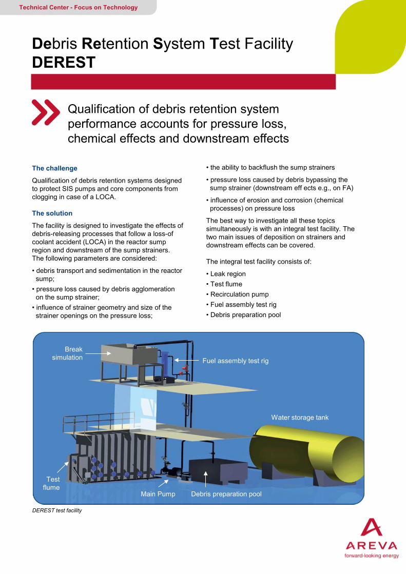
The challenge
Qualification of debris retention systems designed to protect SIS pumps and core components from clogging in case of a LOCA. The solution
The facility is designed to investigate the effects of debris-releasing processes that follow a loss-of coolant accident (LOCA) in the reactor sump region and downstream of the sump strainers. The following parameters are considered:
• debris transport and sedimentation in the reactor sump; • pressure loss caused by debris agglomeration on the sump strainer; • influence of strainer geometry and size of the strainer openings on the pressure loss;
Debris Retention System Test Facility DEREST
Qualification of debris retention system performance accounts for pressure loss, chemical effects and downstream effects
Technical Center - Focus on Technology
• the ability to backflush the sump strainers
• pressure loss caused by debris bypassing the sump strainer (downstream eff ects e.g., on FA)
• influence of erosion and corrosion (chemical processes) on pressure loss
The best way to investigate all these topics simultaneously is with an integral test facility. The two main issues of deposition on strainers and downstream effects can be covered.
The integral test facility consists of:
• Leak region • Test flume • Recirculation pump • Fuel assembly test rig • Debris preparation pool
DEREST test facility
Fuel assembly test rig
Water storage tank
Break simulation
Debris preparation pool
Test flume
Main Pump
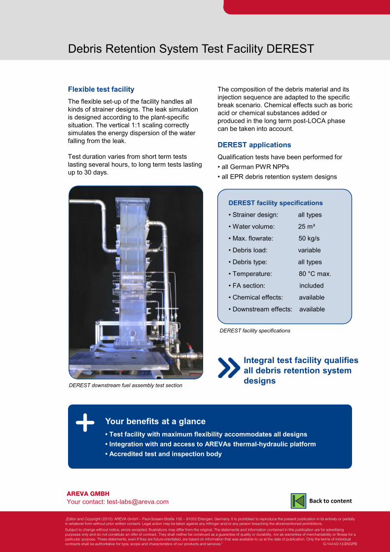
AREVA GMBH Your contact: [email protected]
Debris Retention System Test Facility DEREST
Flexible test facility The flexible set-up of the facility handles all kinds of strainer designs. The leak simulation is designed according to the plant-specific situation. The vertical 1:1 scaling correctly simulates the energy dispersion of the water falling from the leak. Test duration varies from short term tests lasting several hours, to long term tests lasting up to 30 days.
Your benefits at a glance • Test facility with maximum flexibility accommodates all designs • Integration with and access to AREVAs thermal-hydraulic platform • Accredited test and inspection body
DEREST downstream fuel assembly test section
The composition of the debris material and its injection sequence are adapted to the specific break scenario. Chemical effects such as boric acid or chemical substances added or produced in the long term post-LOCA phase can be taken into account. DEREST applications Qualification tests have been performed for • all German PWR NPPs • all EPR debris retention system designs
DEREST facility specifications
Integral test facility qualifies all debris retention system designs
DEREST facility specifications
• Strainer design: all types
• Water volume: 25 m³
• Max. flowrate: 50 kg/s
• Debris load: variable
• Debris type: all types
• Temperature: 80 °C max.
• FA section: included
• Chemical effects: available
• Downstream effects: available
„Editor and Copyright (2015): AREVA GmbH – Paul-Gossen-Straße 100 – 91052 Erlangen, Germany. It is prohibited to reproduce the present publication in its entirety or partially in whatever form without prior written consent. Legal action may be taken against any infringer and/or any person breaching the aforementioned prohibitions.
Subject to change without notice, errors excepted. Illustrations may differ from the original. The statements and information contained in this publication are for advertising purposes only and do not constitute an offer of contract. They shall neither be construed as a guarantee of quality or durability, nor as warranties of merchantability or fitness for a particular purpose. These statements, even if they are future-orientated, are based on information that was available to us at the date of publication. Only the terms of individual contracts shall be authoritative for type, scope and characteristics of our products and services.” G-144-V2-13-ENGPB
Back to content
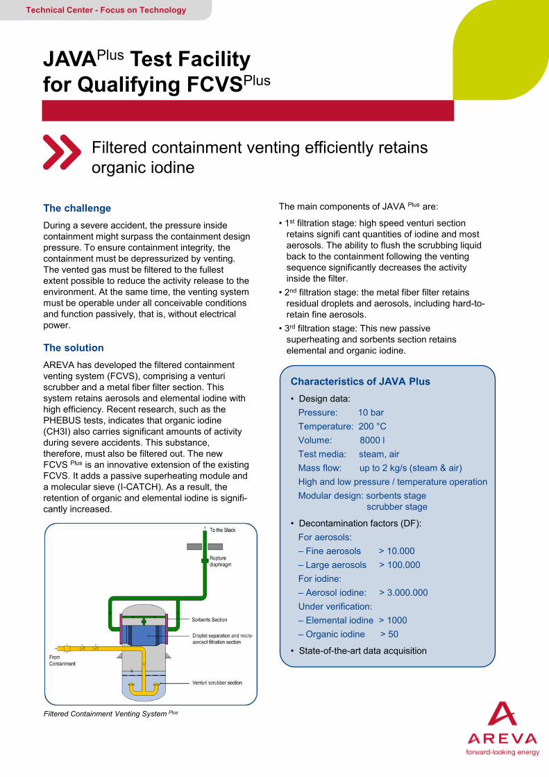
The challenge During a severe accident, the pressure inside containment might surpass the containment design pressure. To ensure containment integrity, the containment must be depressurized by venting. The vented gas must be filtered to the fullest extent possible to reduce the activity release to the environment. At the same time, the venting system must be operable under all conceivable conditions and function passively, that is, without electrical power. The solution AREVA has developed the filtered containment venting system (FCVS), comprising a venturi scrubber and a metal fiber filter section. This system retains aerosols and elemental iodine with high efficiency. Recent research, such as the PHEBUS tests, indicates that organic iodine (CH3I) also carries significant amounts of activity during severe accidents. This substance, therefore, must also be filtered out. The new FCVS Plus is an innovative extension of the existing FCVS. It adds a passive superheating module and a molecular sieve (I-CATCH). As a result, the retention of organic and elemental iodine is signifi- cantly increased.
JAVAPlus Test Facility for Qualifying FCVSPlus
Filtered containment venting efficiently retains organic iodine
Technical Center - Focus on Technology
The main components of JAVA Plus are:
• 1st filtration stage: high speed venturi section retains signifi cant quantities of iodine and most aerosols. The ability to flush the scrubbing liquid back to the containment following the venting sequence significantly decreases the activity inside the filter. • 2nd filtration stage: the metal fiber filter retains residual droplets and aerosols, including hard-to- retain fine aerosols. • 3rd filtration stage: This new passive superheating and sorbents section retains elemental and organic iodine.
Filtered Containment Venting System Plus
Characteristics of JAVA Plus • Design data: Pressure: 10 bar Temperature: 200 °C Volume: 8000 l Test media: steam, air Mass flow: up to 2 kg/s (steam & air) High and low pressure / temperature operation Modular design: sorbents stage scrubber stage
• Decontamination factors (DF): For aerosols: – Fine aerosols > 10.000 – Large aerosols > 100.000 For iodine: – Aerosol iodine: > 3.000.000 Under verification: – Elemental iodine > 1000 – Organic iodine > 50
• State-of-the-art data acquisition
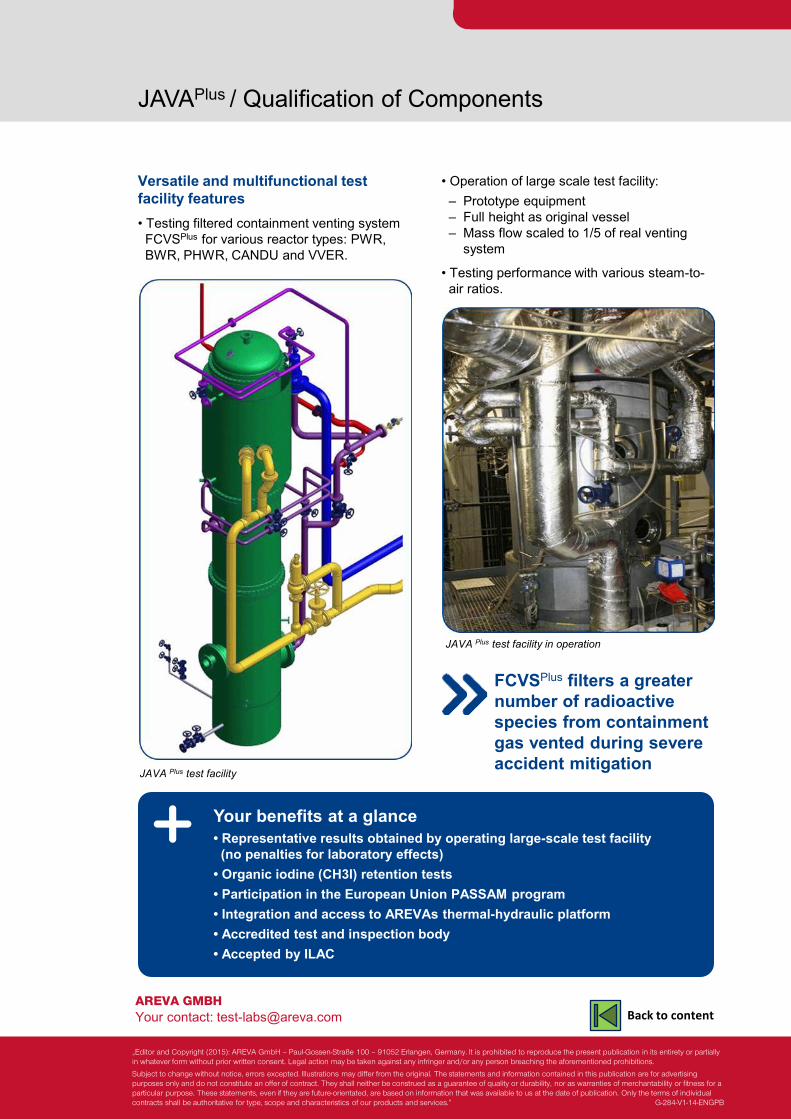
AREVA GMBH Your contact: [email protected]
JAVAPlus / Qualification of Components
Versatile and multifunctional test facility features • Testing filtered containment venting system FCVSPlus for various reactor types: PWR, BWR, PHWR, CANDU and VVER.
Your benefits at a glance • Representative results obtained by operating large-scale test facility (no penalties for laboratory effects) • Organic iodine (CH3I) retention tests • Participation in the European Union PASSAM program • Integration and access to AREVAs thermal-hydraulic platform • Accredited test and inspection body • Accepted by ILAC
JAVA Plus test facility
• Operation of large scale test facility: – Prototype equipment – Full height as original vessel – Mass flow scaled to 1/5 of real venting system
• Testing performance with various steam-to- air ratios.
JAVA Plus test facility in operation
FCVSPlus filters a greater number of radioactive species from containment gas vented during severe accident mitigation
„Editor and Copyright (2015): AREVA GmbH – Paul-Gossen-Straße 100 – 91052 Erlangen, Germany. It is prohibited to reproduce the present publication in its entirety or partially in whatever form without prior written consent. Legal action may be taken against any infringer and/or any person breaching the aforementioned prohibitions.
Subject to change without notice, errors excepted. Illustrations may differ from the original. The statements and information contained in this publication are for advertising purposes only and do not constitute an offer of contract. They shall neither be construed as a guarantee of quality or durability, nor as warranties of merchantability or fitness for a particular purpose. These statements, even if they are future-orientated, are based on information that was available to us at the date of publication. Only the terms of individual contracts shall be authoritative for type, scope and characteristics of our products and services.” G-284-V1-14-ENGPB
Back to content
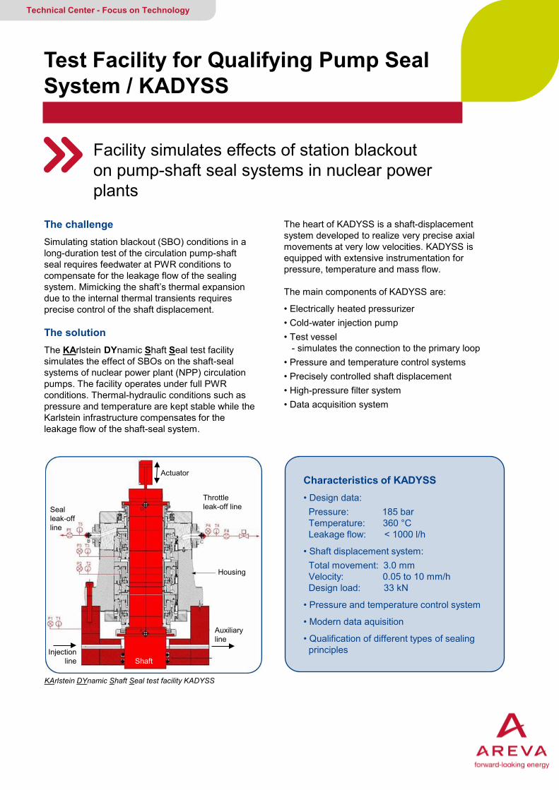
The challenge Simulating station blackout (SBO) conditions in a long-duration test of the circulation pump-shaft seal requires feedwater at PWR conditions to compensate for the leakage flow of the sealing system. Mimicking the shaft’s thermal expansion due to the internal thermal transients requires precise control of the shaft displacement. The solution The KArlstein DYnamic Shaft Seal test facility simulates the effect of SBOs on the shaft-seal systems of nuclear power plant (NPP) circulation pumps. The facility operates under full PWR conditions. Thermal-hydraulic conditions such as pressure and temperature are kept stable while the Karlstein infrastructure compensates for the leakage flow of the shaft-seal system.
Test Facility for Qualifying Pump Seal System / KADYSS
Facility simulates effects of station blackout on pump-shaft seal systems in nuclear power plants
Technical Center - Focus on Technology
The heart of KADYSS is a shaft-displacement system developed to realize very precise axial movements at very low velocities. KADYSS is equipped with extensive instrumentation for pressure, temperature and mass flow.
The main components of KADYSS are:
• Electrically heated pressurizer • Cold-water injection pump • Test vessel - simulates the connection to the primary loop • Pressure and temperature control systems • Precisely controlled shaft displacement • High-pressure filter system • Data acquisition system
KArlstein DYnamic Shaft Seal test facility KADYSS
Characteristics of KADYSS • Design data: Pressure: 185 bar Temperature: 360 °C Leakage flow: < 1000 l/h
• Shaft displacement system: Total movement: 3.0 mm Velocity: 0.05 to 10 mm/h Design load: 33 kN
• Pressure and temperature control system
• Modern data aquisition
• Qualification of different types of sealing principles
Housing
Actuator
Shaft Injection
line
Auxiliary line
Throttle leak-off line Seal
leak-off line
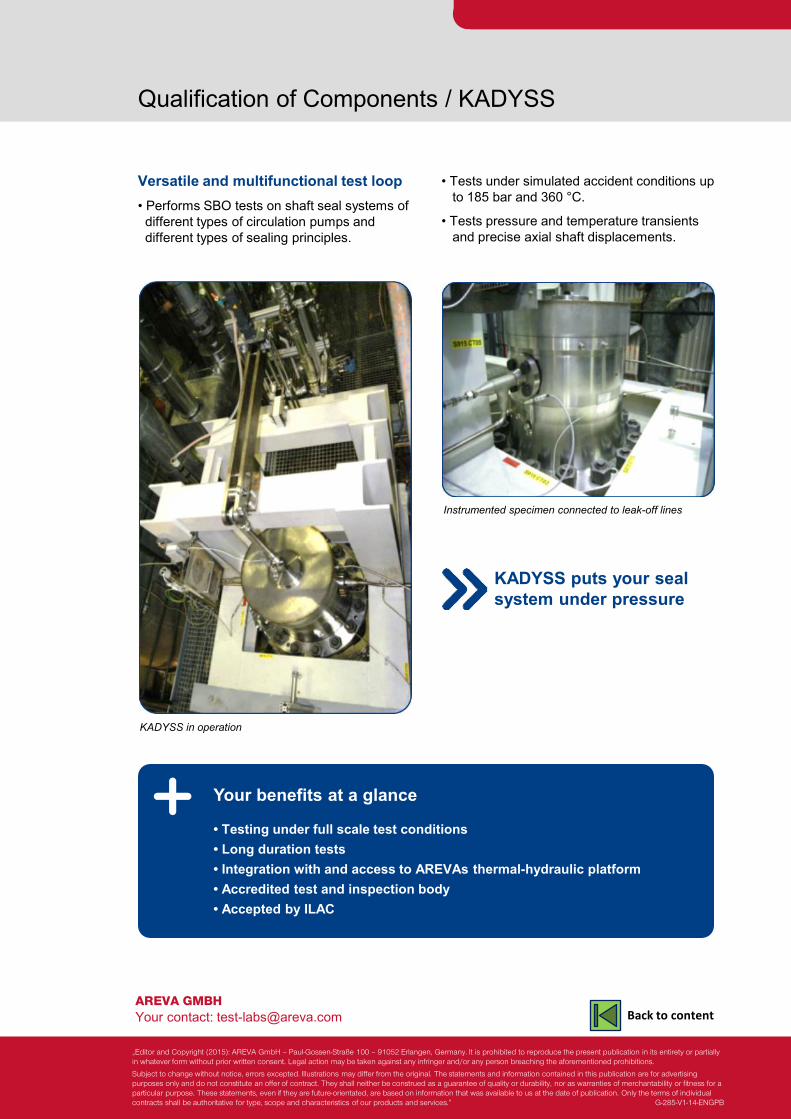
AREVA GMBH Your contact: [email protected]
Qualification of Components / KADYSS
Versatile and multifunctional test loop • Performs SBO tests on shaft seal systems of different types of circulation pumps and different types of sealing principles.
Your benefits at a glance • Testing under full scale test conditions • Long duration tests • Integration with and access to AREVAs thermal-hydraulic platform • Accredited test and inspection body • Accepted by ILAC
KADYSS in operation
• Tests under simulated accident conditions up to 185 bar and 360 °C.
• Tests pressure and temperature transients and precise axial shaft displacements.
Instrumented specimen connected to leak-off lines
KADYSS puts your seal system under pressure
„Editor and Copyright (2015): AREVA GmbH – Paul-Gossen-Straße 100 – 91052 Erlangen, Germany. It is prohibited to reproduce the present publication in its entirety or partially in whatever form without prior written consent. Legal action may be taken against any infringer and/or any person breaching the aforementioned prohibitions.
Subject to change without notice, errors excepted. Illustrations may differ from the original. The statements and information contained in this publication are for advertising purposes only and do not constitute an offer of contract. They shall neither be construed as a guarantee of quality or durability, nor as warranties of merchantability or fitness for a particular purpose. These statements, even if they are future-orientated, are based on information that was available to us at the date of publication. Only the terms of individual contracts shall be authoritative for type, scope and characteristics of our products and services.” G-285-V1-14-ENGPB
Back to content
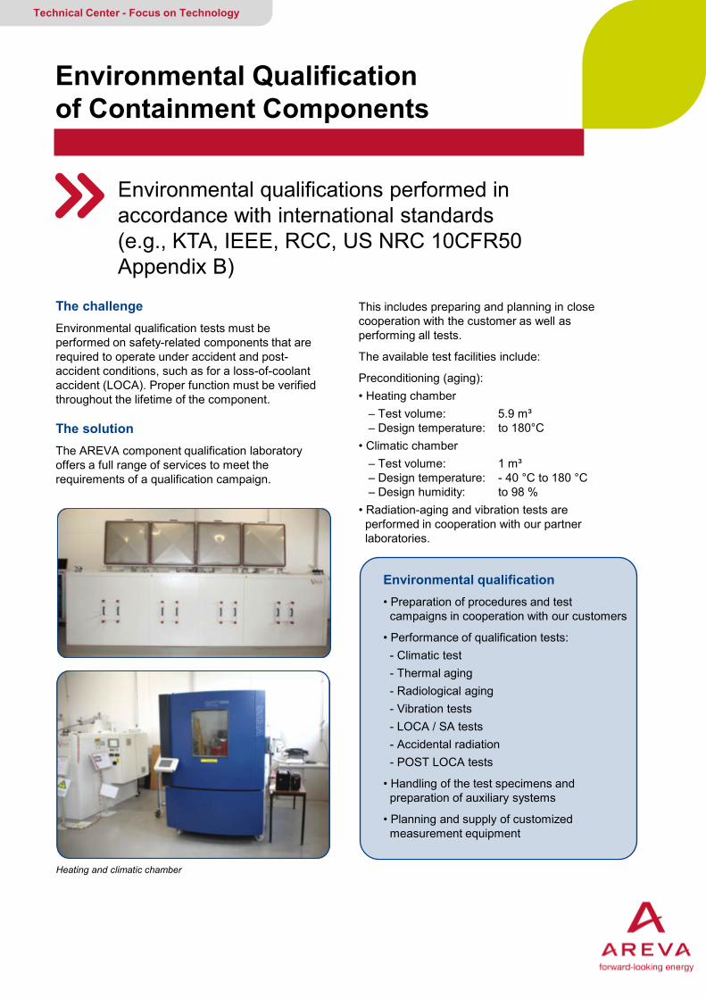
The challenge Environmental qualification tests must be performed on safety-related components that are required to operate under accident and post-accident conditions, such as for a loss-of-coolant accident (LOCA). Proper function must be verified throughout the lifetime of the component. The solution The AREVA component qualification laboratory offers a full range of services to meet the requirements of a qualification campaign.
Environmental Qualification of Containment Components
Environmental qualifications performed in accordance with international standards (e.g., KTA, IEEE, RCC, US NRC 10CFR50 Appendix B)
Technical Center - Focus on Technology
This includes preparing and planning in close cooperation with the customer as well as performing all tests.
The available test facilities include:
Preconditioning (aging): • Heating chamber – Test volume: 5.9 m³ – Design temperature: to 180°C • Climatic chamber – Test volume: 1 m³ – Design temperature: - 40 °C to 180 °C – Design humidity: to 98 % • Radiation-aging and vibration tests are performed in cooperation with our partner laboratories.
Heating and climatic chamber
Environmental qualification • Preparation of procedures and test campaigns in cooperation with our customers
• Performance of qualification tests: - Climatic test - Thermal aging - Radiological aging - Vibration tests - LOCA / SA tests - Accidental radiation - POST LOCA tests
• Handling of the test specimens and preparation of auxiliary systems
• Planning and supply of customized measurement equipment
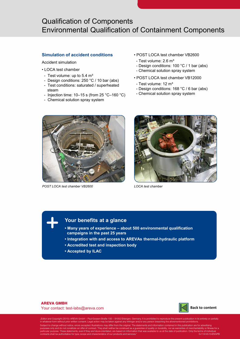
AREVA GMBH Your contact: [email protected]
Qualification of Components Environmental Qualification of Containment Components
Simulation of accident conditions Accident simulation
• LOCA test chamber - Test volume: up to 5.4 m³ - Design conditions: 250 °C / 10 bar (abs) - Test conditions: saturated / superheated steam - Injection time: 10–15 s (from 25 °C–160 °C) - Chemical solution spray system
Your benefits at a glance • Many years of experience – about 500 environmental qualification campaigns in the past 25 years • Integration with and access to AREVAs thermal-hydraulic platform • Accredited test and inspection body • Accepted by ILAC
LOCA test chamber
• POST LOCA test chamber VB2600 - Test volume: 2.6 m³ - Design conditions: 100 °C / 1 bar (abs) - Chemical solution spray system
• POST LOCA test chamber VB12000 - Test volume: 12 m³ - Design conditions: 168 °C / 6 bar (abs) - Chemical solution spray system
I
POST LOCA test chamber VB2600
„Editor and Copyright (2015): AREVA GmbH – Paul-Gossen-Straße 100 – 91052 Erlangen, Germany. It is prohibited to reproduce the present publication in its entirety or partially in whatever form without prior written consent. Legal action may be taken against any infringer and/or any person breaching the aforementioned prohibitions.
Subject to change without notice, errors excepted. Illustrations may differ from the original. The statements and information contained in this publication are for advertising purposes only and do not constitute an offer of contract. They shall neither be construed as a guarantee of quality or durability, nor as warranties of merchantability or fitness for a particular purpose. These statements, even if they are future-orientated, are based on information that was available to us at the date of publication. Only the terms of individual contracts shall be authoritative for type, scope and characteristics of our products and services.” G-113-V3-13-ENGPB
Back to content
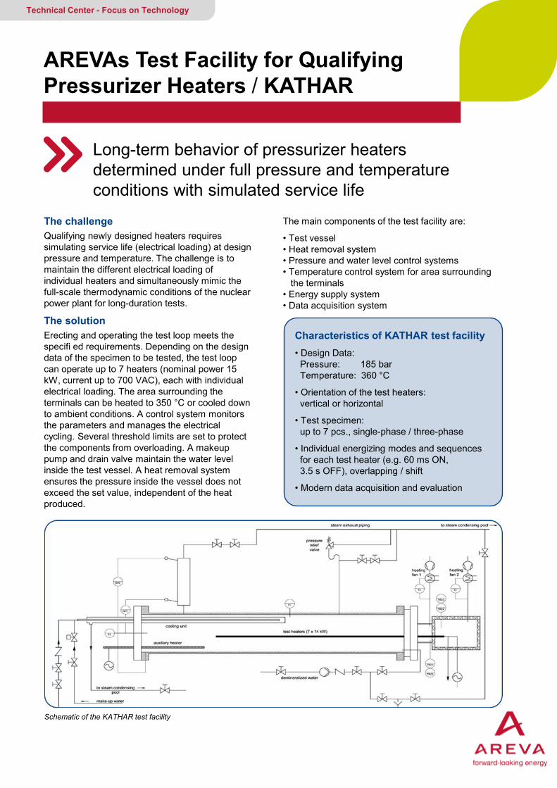
The challenge Qualifying newly designed heaters requires simulating service life (electrical loading) at design pressure and temperature. The challenge is to maintain the different electrical loading of individual heaters and simultaneously mimic the full-scale thermodynamic conditions of the nuclear power plant for long-duration tests.
The solution Erecting and operating the test loop meets the specifi ed requirements. Depending on the design data of the specimen to be tested, the test loop can operate up to 7 heaters (nominal power 15 kW, current up to 700 VAC), each with individual electrical loading. The area surrounding the terminals can be heated to 350 °C or cooled down to ambient conditions. A control system monitors the parameters and manages the electrical cycling. Several threshold limits are set to protect the components from overloading. A makeup pump and drain valve maintain the water level inside the test vessel. A heat removal system ensures the pressure inside the vessel does not exceed the set value, independent of the heat produced.
AREVAs Test Facility for Qualifying Pressurizer Heaters / KATHAR
Long-term behavior of pressurizer heaters determined under full pressure and temperature conditions with simulated service life
Technical Center - Focus on Technology
The main components of the test facility are:
• Test vessel • Heat removal system • Pressure and water level control systems • Temperature control system for area surrounding the terminals • Energy supply system • Data acquisition system
Schematic of the KATHAR test facility
Characteristics of KATHAR test facility • Design Data: Pressure: 185 bar Temperature: 360 °C
• Orientation of the test heaters: vertical or horizontal
• Test specimen: up to 7 pcs., single-phase / three-phase
• Individual energizing modes and sequences for each test heater (e.g. 60 ms ON, 3.5 s OFF), overlapping / shift
• Modern data acquisition and evaluation
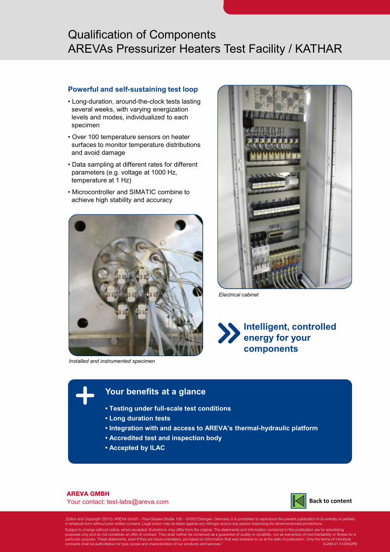
AREVA GMBH Your contact: [email protected]
Qualification of Components AREVAs Pressurizer Heaters Test Facility / KATHAR
Powerful and self-sustaining test loop • Long-duration, around-the-clock tests lasting several weeks, with varying energization levels and modes, individualized to each specimen
• Over 100 temperature sensors on heater surfaces to monitor temperature distributions and avoid damage
• Data sampling at different rates for different parameters (e.g. voltage at 1000 Hz, temperature at 1 Hz)
• Microcontroller and SIMATIC combine to achieve high stability and accuracy
Your benefits at a glance • Testing under full-scale test conditions • Long duration tests • Integration with and access to AREVA’s thermal-hydraulic platform • Accredited test and inspection body • Accepted by ILAC
Installed and instrumented specimen
Electrical cabinet
Intelligent, controlled energy for your components
„Editor and Copyright (2015): AREVA GmbH – Paul-Gossen-Straße 100 – 91052 Erlangen, Germany. It is prohibited to reproduce the present publication in its entirety or partially in whatever form without prior written consent. Legal action may be taken against any infringer and/or any person breaching the aforementioned prohibitions.
Subject to change without notice, errors excepted. Illustrations may differ from the original. The statements and information contained in this publication are for advertising purposes only and do not constitute an offer of contract. They shall neither be construed as a guarantee of quality or durability, nor as warranties of merchantability or fitness for a particular purpose. These statements, even if they are future-orientated, are based on information that was available to us at the date of publication. Only the terms of individual contracts shall be authoritative for type, scope and characteristics of our products and services.” G-286-V1-14-ENGPB
Back to content
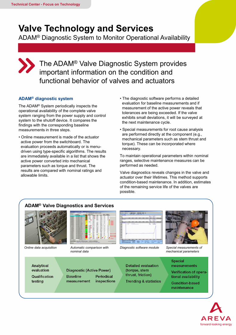
ADAM® diagnostic system The ADAM® System periodically inspects the operational availability of the complete valve system ranging from the power supply and control system to the shutoff device. It compares the findings with the corresponding baseline measurements in three steps.
• Online measurement is made of the actuator active power from the switchboard. The evaluation proceeds automatically or is menu- driven using type-specific algorithms. The results are immediately available in a list that shows the active power converted into mechanical parameters such as torque and thrust. The results are compared with nominal ratings and allowable limits.
Valve Technology and Services ADAM® Diagnostic System to Monitor Operational Availability
The ADAM® Valve Diagnostic System provides important information on the condition and functional behavior of valves and actuators
Technical Center - Focus on Technology
• The diagnostic software performs a detailed evaluation for baseline measurements and if measurement of the active power reveals that tolerances are being exceeded. If the valve exhibits small deviations, it will be surveyed at the next maintenance cycle.
• Special measurements for root cause analysis are performed directly at the component (e.g., mechanical parameters such as stem thrust and torque). These can be incorporated where necessary.
To maintain operational parameters within nominal ranges, selective maintenance measures can be performed as needed.
Valve diagnostics reveals changes in the valve and actuator over their lifetimes. This method supports condition-based maintenance. In addition, estimates of the remaining service life of the valves are possible.
ADAM® Valve Diagnostics and Services
Online data acquisition Automatic comparison with nominal data
Diagnostic software module Special measurements of mechanical parameters
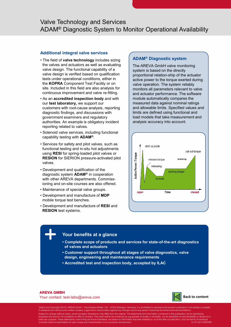
AREVA GMBH Your contact: [email protected]
Valve Technology and Services ADAM® Diagnostic System to Monitor Operational Availability
Additional integral valve services • The field of valve technology includes sizing the valves and actuators as well as evaluating valve design. The functional capability of a valve design is verified based on qualification tests under operational conditions, either in the KOPRA Component Test Facility or on site. Included in this field are also analysis for continuous improvement and valve re-fitting. • As an accredited inspection body and with our test laboratory, we support our customers with root-cause analysis, reporting diagnostic findings, and discussions with government examiners and regulatory authorities. An example is obligatory incident reporting related to valves. • Solenoid valve services, including functional capability testing with ADAM®.
• Services for safety and pilot valves, such as functional testing and in-situ hot adjustments using RESI for spring-loaded pilot valves or RESION for SIERION pressure-activated pilot valves.
• Development and qualification of the diagnostic system ADAM® in cooperation with other AREVA departments. Commiss- ioning and on-site courses are also offered. • Maintenance of special valve groups. • Development and manufacture of MDP mobile torque test benches. • Development and manufacture of RESI and RESION test systems.
Your benefits at a glance • Complete scope of products and services for state-of-the-art diagnostics of valves and actuators • Customer support throughout all stages of valve diagnostics, valve design, engineering and maintenance requirements • Accredited test and inspection body, accepted by ILAC
ADAM® Diagnostic system The AREVA GmbH valve monitoring system is based on the directly proportional relation-ship of the actuator active power to the torque exerted during valve operation. The system reliably monitors all parameters relevant to valve and actuator performance. The software module automatically compares the measured data against nominal ratings and allowable limits. Specified values and limits are defined using functional and load models that take measurement and analysis accuracy into account.
„Editor and Copyright (2015): AREVA GmbH – Paul-Gossen-Straße 100 – 91052 Erlangen, Germany. It is prohibited to reproduce the present publication in its entirety or partially in whatever form without prior written consent. Legal action may be taken against any infringer and/or any person breaching the aforementioned prohibitions.
Subject to change without notice, errors excepted. Illustrations may differ from the original. The statements and information contained in this publication are for advertising purposes only and do not constitute an offer of contract. They shall neither be construed as a guarantee of quality or durability, nor as warranties of merchantability or fitness for a particular purpose. These statements, even if they are future-orientated, are based on information that was available to us at the date of publication. Only the terms of individual contracts shall be authoritative for type, scope and characteristics of our products and services.” G-131-V2-13-ENGPB
Back to content
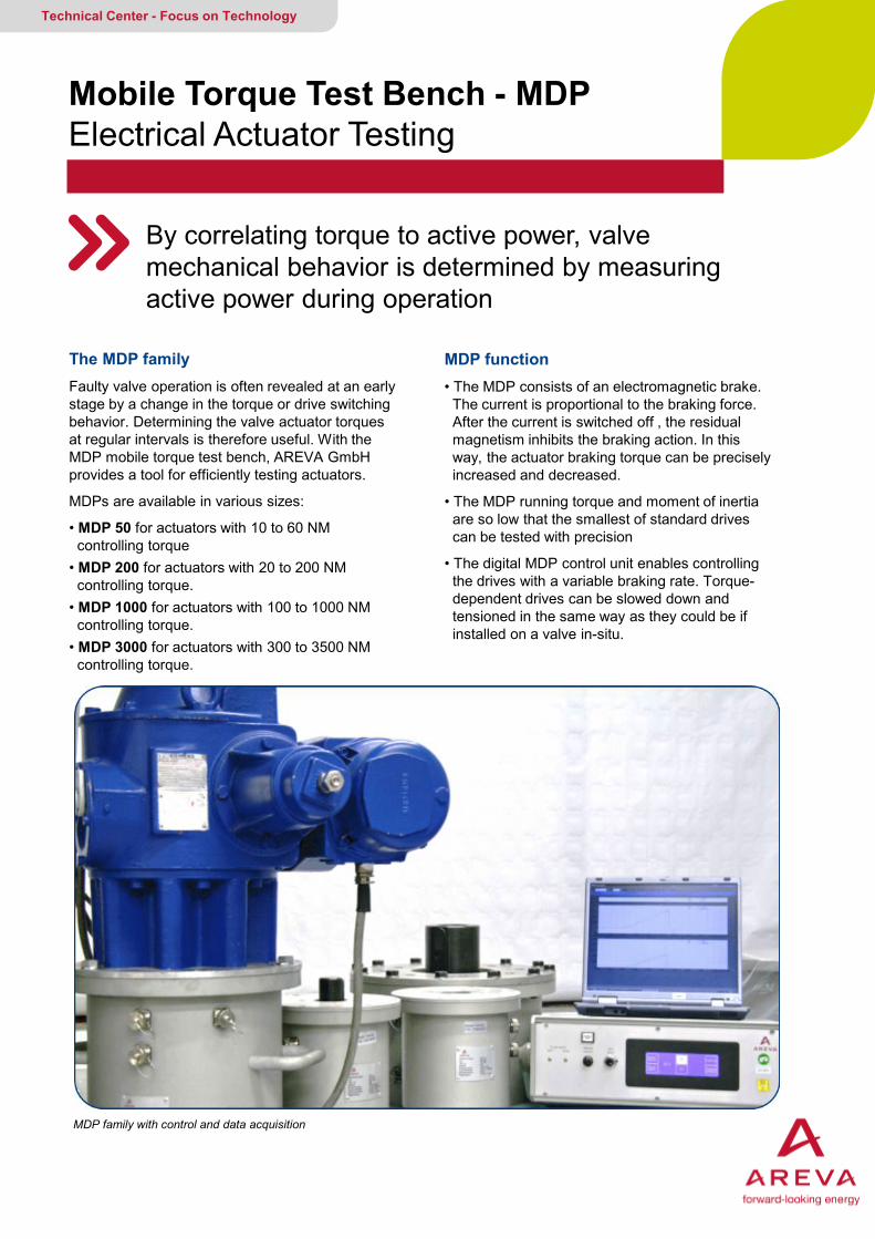
The MDP family Faulty valve operation is often revealed at an early stage by a change in the torque or drive switching behavior. Determining the valve actuator torques at regular intervals is therefore useful. With the MDP mobile torque test bench, AREVA GmbH provides a tool for efficiently testing actuators.
MDPs are available in various sizes:
• MDP 50 for actuators with 10 to 60 NM controlling torque • MDP 200 for actuators with 20 to 200 NM controlling torque. • MDP 1000 for actuators with 100 to 1000 NM controlling torque. • MDP 3000 for actuators with 300 to 3500 NM controlling torque.
Mobile Torque Test Bench - MDP Electrical Actuator Testing
By correlating torque to active power, valve mechanical behavior is determined by measuring active power during operation
Technical Center - Focus on Technology
MDP function • The MDP consists of an electromagnetic brake. The current is proportional to the braking force. After the current is switched off , the residual magnetism inhibits the braking action. In this way, the actuator braking torque can be precisely increased and decreased.
• The MDP running torque and moment of inertia are so low that the smallest of standard drives can be tested with precision
• The digital MDP control unit enables controlling the drives with a variable braking rate. Torque- dependent drives can be slowed down and tensioned in the same way as they could be if installed on a valve in-situ.
MDP family with control and data acquisition
MDP 3000
MDP 1000
MDP 50 MDP 200
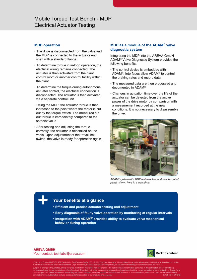
AREVA GMBH Your contact: [email protected]
Mobile Torque Test Bench - MDP Electrical Actuator Testing
MDP operation • The drive is disconnected from the valve and the MDP is connected to the actuator end shaft with a standard flange.
• To determine torque in in-loop operation, the electrical wiring remains connected. The actuator is then activated from the plant control room or another control facility within the plant.
• To determine the torque during autonomous actuator control, the electrical connection is disconnected. The actuator is then activated via a separate control unit.
• Using the MDP, the actuator torque is then increased to the point where the motor is cut out by the torque switch. The measured cut out torque is immediately compared to the setpoint value.
• After testing and adjusting the torque correctly, the actuator is reinstalled on the valve. Upon adjustment of the travel limit switch, the valve is ready for operation again.
Your benefits at a glance • Efficient and precise actuator testing and adjustment
• Early diagnosis of faulty valve operation by monitoring at regular intervals
• Integration with ADAM provides ability to evaluate valve mechanical behavior during operation
MDP as a module of the ADAM® valve diagnostic system Integrating the MDP into the AREVA GmbH ADAM® Valve Diagnostic System provides the following benefits:
• The control device is embedded within ADAM®. Interfaces allow ADAM® to control the braking rates and record data.
• The measured data are then processed and documented in ADAM®
• Changes in actuation time over the life of the actuator can be detected from the active power of the drive motor by comparison with a measurement recorded at the new conditions. It is not necessary to disassemble the drive.
ADAM® system with MDP test benches and bench control panel, shown here in a workshop.
„Editor and Copyright (2015): AREVA GmbH – Paul-Gossen-Straße 100 – 91052 Erlangen, Germany. It is prohibited to reproduce the present publication in its entirety or partially in whatever form without prior written consent. Legal action may be taken against any infringer and/or any person breaching the aforementioned prohibitions.
Subject to change without notice, errors excepted. Illustrations may differ from the original. The statements and information contained in this publication are for advertising purposes only and do not constitute an offer of contract. They shall neither be construed as a guarantee of quality or durability, nor as warranties of merchantability or fitness for a particular purpose. These statements, even if they are future-orientated, are based on information that was available to us at the date of publication. Only the terms of individual contracts shall be authoritative for type, scope and characteristics of our products and services.” G-135-V2-13-ENGPB
Back to content
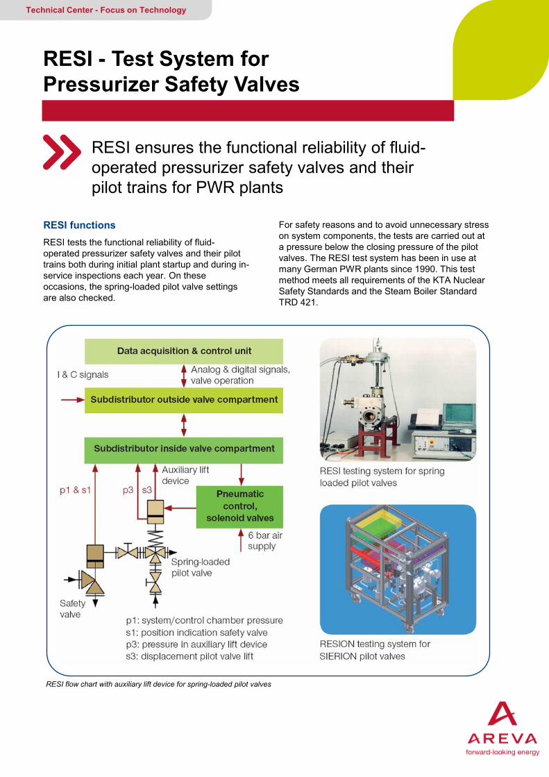
RESI functions RESI tests the functional reliability of fluid-operated pressurizer safety valves and their pilot trains both during initial plant startup and during in-service inspections each year. On these occasions, the spring-loaded pilot valve settings are also checked.
RESI - Test System for Pressurizer Safety Valves
RESI ensures the functional reliability of fluid- operated pressurizer safety valves and their pilot trains for PWR plants
Technical Center - Focus on Technology
For safety reasons and to avoid unnecessary stress on system components, the tests are carried out at a pressure below the closing pressure of the pilot valves. The RESI test system has been in use at many German PWR plants since 1990. This test method meets all requirements of the KTA Nuclear Safety Standards and the Steam Boiler Standard TRD 421.
RESI flow chart with auxiliary lift device for spring-loaded pilot valves
AREVA GMBH Your contact: [email protected]
RESI - Test System for Pressurizer Safety Valves
RESI records valve lift and opening and closing pressures. The system automatically and immediately determines test results, such as opening and closing reliability, opening and closing delay times and closing differential pressure. The automatic test sequence ensures reproducible test results in all cases.
Plug connectors in permanently installed cabling and subdistributors provide considerable time savings, particularly during test-system setup, test preparations, and transfer from one valve to the next. These savings in time, along with operating the controls from a location outside the valve compartment, reduce the radiation exposure of test personnel.
The main features are:
• Less stress on the valves due to extreme system pressure reduction during the test.
• In-service adjustment of spring-loaded pilot valves below their closing pressure without primary loop transients.
• Remarkable time saving due to ease of test preparation, as well as to automated testing, evaluation and documentation
• Easy realization of customer-specific changes in test procedure and documentation.
• Self monitoring system reliably prevents unintentional opening of the pilot valves in the event of fault.
Your benefits at a glance • Ensures functional reliability of fluid-operated pressurizer safety valves for PWR plants • Avoids unnecessary stress of system components by testing at lower pressure • Approved test method meets all KTA and steam boiler standard TRD 421 requirements
RESI applications RESI is used on all kinds of spring-loaded pressurizer safety valves, regardless of their operation principle, whether based on pressurization or depressurization. The system is suitable for a wide range of tests, including:
• Pressure-relief valves
• Setting tests for spring-loaded pilot valves performed below their closing pressures (approx. 135 bar).
• Testing pressurizer safety valve actuating force at partial pilot lift.
• Functional testing of the relief train.
• Functional testing of the primary-system bleed function of safety and relief valves, including the associated pilot valves.
• The RESION test system has been developed for testing the settings of SIERION pilot valves actuated by static pressure
„Editor and Copyright (2015): AREVA GmbH – Paul-Gossen-Straße 100 – 91052 Erlangen, Germany. It is prohibited to reproduce the present publication in its entirety or partially in whatever form without prior written consent. Legal action may be taken against any infringer and/or any person breaching the aforementioned prohibitions.
Subject to change without notice, errors excepted. Illustrations may differ from the original. The statements and information contained in this publication are for advertising purposes only and do not constitute an offer of contract. They shall neither be construed as a guarantee of quality or durability, nor as warranties of merchantability or fitness for a particular purpose. These statements, even if they are future-orientated, are based on information that was available to us at the date of publication. Only the terms of individual contracts shall be authoritative for type, scope and characteristics of our products and services.” G-137-V2-13-ENGPB
Back to content
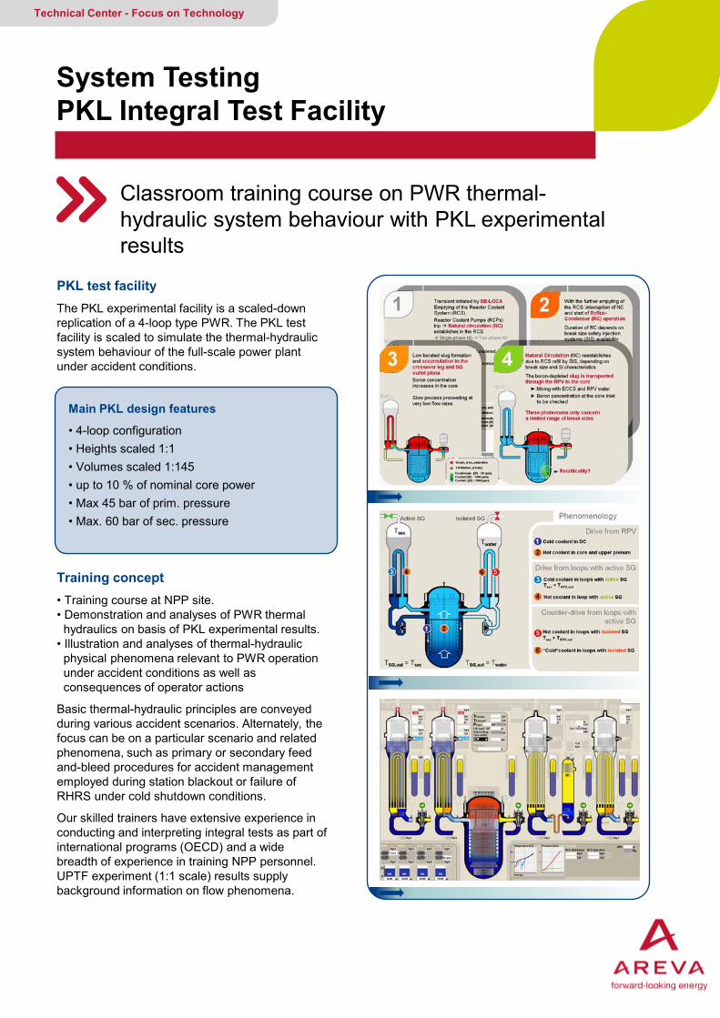
PKL test facility The PKL experimental facility is a scaled-down replication of a 4-loop type PWR. The PKL test facility is scaled to simulate the thermal-hydraulic system behaviour of the full-scale power plant under accident conditions.
Training concept • Training course at NPP site. • Demonstration and analyses of PWR thermal hydraulics on basis of PKL experimental results. • Illustration and analyses of thermal-hydraulic physical phenomena relevant to PWR operation under accident conditions as well as consequences of operator actions
Basic thermal-hydraulic principles are conveyed during various accident scenarios. Alternately, the focus can be on a particular scenario and related phenomena, such as primary or secondary feed and-bleed procedures for accident management employed during station blackout or failure of RHRS under cold shutdown conditions.
Our skilled trainers have extensive experience in conducting and interpreting integral tests as part of international programs (OECD) and a wide breadth of experience in training NPP personnel. UPTF experiment (1:1 scale) results supply background information on flow phenomena.
System Testing PKL Integral Test Facility
Classroom training course on PWR thermal- hydraulic system behaviour with PKL experimental results
Technical Center - Focus on Technology
Main PKL design features
• 4-loop configuration • Heights scaled 1:1 • Volumes scaled 1:145 • up to 10 % of nominal core power • Max 45 bar of prim. pressure • Max. 60 bar of sec. pressure
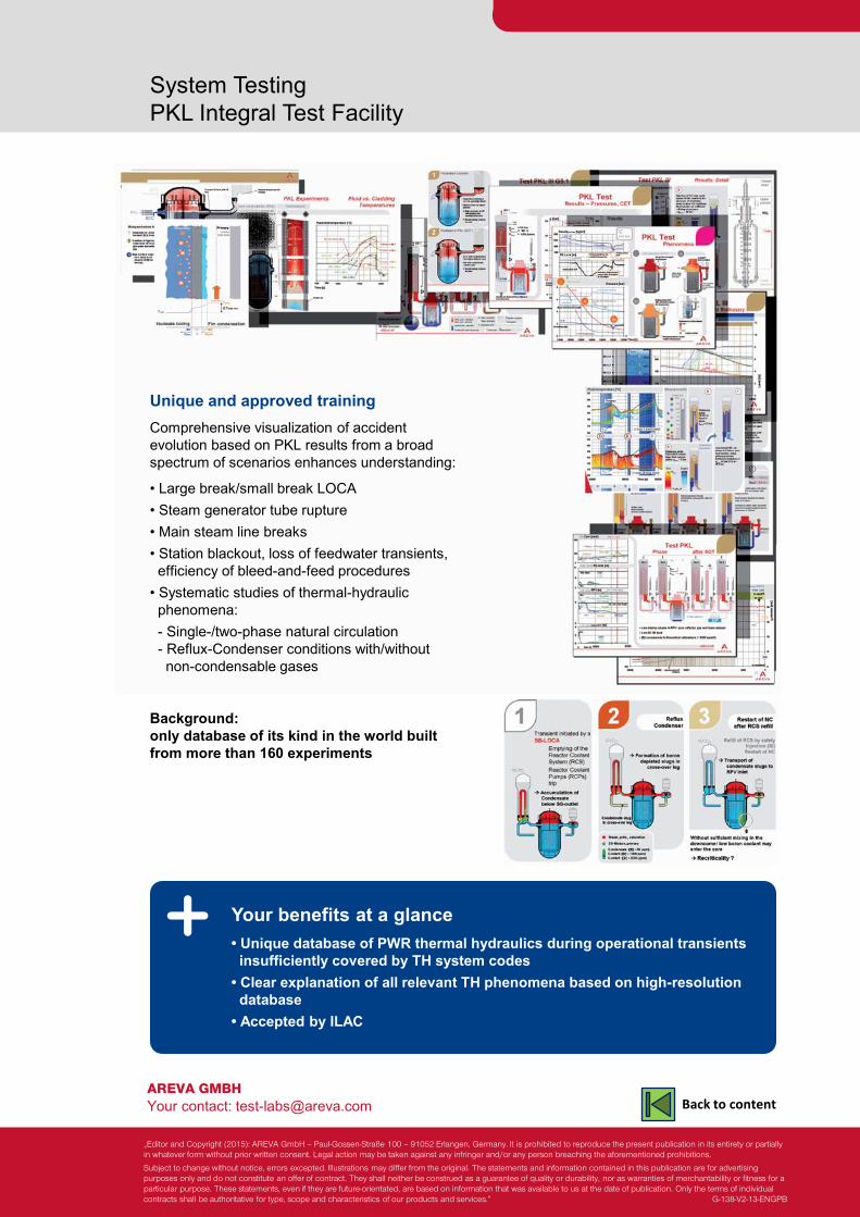
AREVA GMBH Your contact: [email protected]
System Testing PKL Integral Test Facility
Your benefits at a glance • Unique database of PWR thermal hydraulics during operational transients insufficiently covered by TH system codes • Clear explanation of all relevant TH phenomena based on high-resolution database • Accepted by ILAC
Unique and approved training Comprehensive visualization of accident evolution based on PKL results from a broad spectrum of scenarios enhances understanding:
• Large break/small break LOCA • Steam generator tube rupture • Main steam line breaks • Station blackout, loss of feedwater transients, efficiency of bleed-and-feed procedures • Systematic studies of thermal-hydraulic phenomena: - Single-/two-phase natural circulation - Reflux-Condenser conditions with/without non-condensable gases
Background: only database of its kind in the world built from more than 160 experiments
„Editor and Copyright (2015): AREVA GmbH – Paul-Gossen-Straße 100 – 91052 Erlangen, Germany. It is prohibited to reproduce the present publication in its entirety or partially in whatever form without prior written consent. Legal action may be taken against any infringer and/or any person breaching the aforementioned prohibitions.
Subject to change without notice, errors excepted. Illustrations may differ from the original. The statements and information contained in this publication are for advertising purposes only and do not constitute an offer of contract. They shall neither be construed as a guarantee of quality or durability, nor as warranties of merchantability or fitness for a particular purpose. These statements, even if they are future-orientated, are based on information that was available to us at the date of publication. Only the terms of individual contracts shall be authoritative for type, scope and characteristics of our products and services.” G-138-V2-13-ENGPB
Back to content
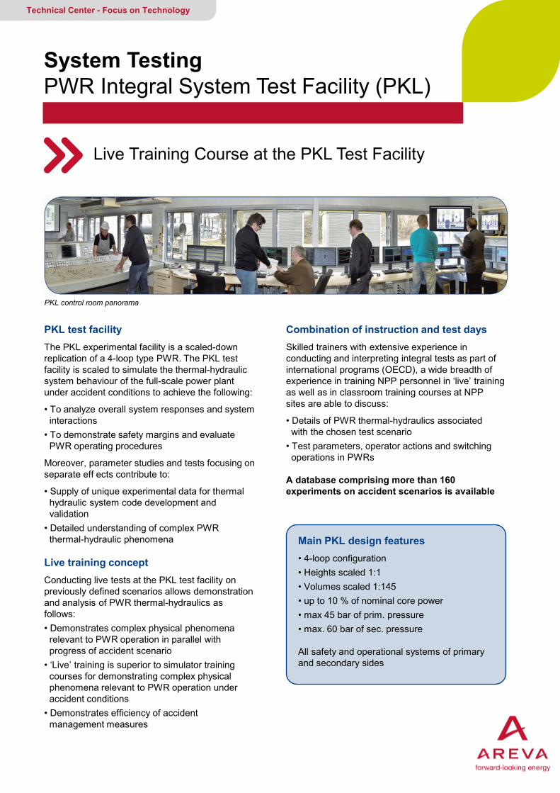
PKL test facility The PKL experimental facility is a scaled-down replication of a 4-loop type PWR. The PKL test facility is scaled to simulate the thermal-hydraulic system behaviour of the full-scale power plant under accident conditions to achieve the following:
• To analyze overall system responses and system interactions • To demonstrate safety margins and evaluate PWR operating procedures
Moreover, parameter studies and tests focusing on separate eff ects contribute to:
• Supply of unique experimental data for thermal hydraulic system code development and validation • Detailed understanding of complex PWR thermal-hydraulic phenomena
Live training concept Conducting live tests at the PKL test facility on previously defined scenarios allows demonstration and analysis of PWR thermal-hydraulics as follows: • Demonstrates complex physical phenomena relevant to PWR operation in parallel with progress of accident scenario • ‘Live’ training is superior to simulator training courses for demonstrating complex physical phenomena relevant to PWR operation under accident conditions • Demonstrates efficiency of accident management measures
System Testing PWR Integral System Test Facility (PKL)
Live Training Course at the PKL Test Facility
Technical Center - Focus on Technology
Combination of instruction and test days Skilled trainers with extensive experience in conducting and interpreting integral tests as part of international programs (OECD), a wide breadth of experience in training NPP personnel in ‘live’ training as well as in classroom training courses at NPP sites are able to discuss:
• Details of PWR thermal-hydraulics associated with the chosen test scenario • Test parameters, operator actions and switching operations in PWRs
A database comprising more than 160 experiments on accident scenarios is available
Main PKL design features • 4-loop configuration • Heights scaled 1:1 • Volumes scaled 1:145 • up to 10 % of nominal core power • max 45 bar of prim. pressure • max. 60 bar of sec. pressure
All safety and operational systems of primary and secondary sides
PKL control room panorama
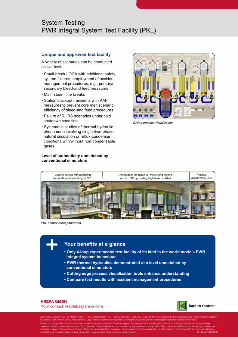
AREVA GMBH Your contact: [email protected]
System Testing PWR Integral System Test Facility (PKL)
Unique and approved test facility A variety of scenarios can be conducted as live tests:
• Small-break LOCA with additional safety system failures, employment of accident management procedures, e.g., primary/ secondary bleed-and feed measures • Main steam line breaks • Station blackout transients with AM- measures to prevent core melt scenario, efficiency of bleed-and feed procedures • Failure of RHRS scenarios under cold shutdown condition • Systematic studies of thermal-hydraulic phenomena involving single-/two-phase natural circulation or reflux-condenser conditions with/without non-condensable gases Level of authenticity unmatched by conventional simulators
Your benefits at a glance • Only 4-loop experimental test facility of its kind in the world models PWR integral system behaviour • PWR thermal hydraulics demonstrated at a level unmatched by conventional simulators • Cutting edge process visualization tools enhance understanding • Compare test results with accident management procedures
Online process visualization
PKL control room panorama
Process visualization tools
Observation of individual measuring signals (up to 1500) providing high level of detail
Control panels with switching elements corresponding to NPP
„Editor and Copyright (2015): AREVA GmbH – Paul-Gossen-Straße 100 – 91052 Erlangen, Germany. It is prohibited to reproduce the present publication in its entirety or partially in whatever form without prior written consent. Legal action may be taken against any infringer and/or any person breaching the aforementioned prohibitions.
Subject to change without notice, errors excepted. Illustrations may differ from the original. The statements and information contained in this publication are for advertising purposes only and do not constitute an offer of contract. They shall neither be construed as a guarantee of quality or durability, nor as warranties of merchantability or fitness for a particular purpose. These statements, even if they are future-orientated, are based on information that was available to us at the date of publication. Only the terms of individual contracts shall be authoritative for type, scope and characteristics of our products and services.” G-149-V2-13-ENGPB
Back to content
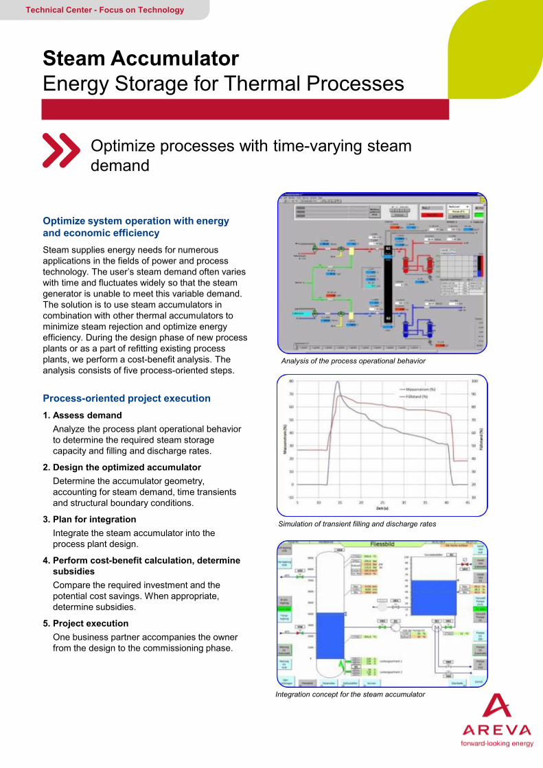
Steam Accumulator Energy Storage for Thermal Processes
Optimize processes with time-varying steam demand
Technical Center - Focus on Technology
Optimize system operation with energy and economic efficiency Steam supplies energy needs for numerous applications in the fields of power and process technology. The user’s steam demand often varies with time and fluctuates widely so that the steam generator is unable to meet this variable demand. The solution is to use steam accumulators in combination with other thermal accumulators to minimize steam rejection and optimize energy efficiency. During the design phase of new process plants or as a part of refitting existing process plants, we perform a cost-benefit analysis. The analysis consists of five process-oriented steps.
Process-oriented project execution 1. Assess demand Analyze the process plant operational behavior to determine the required steam storage capacity and filling and discharge rates.
2. Design the optimized accumulator Determine the accumulator geometry, accounting for steam demand, time transients and structural boundary conditions.
3. Plan for integration Integrate the steam accumulator into the process plant design.
4. Perform cost-benefit calculation, determine subsidies Compare the required investment and the potential cost savings. When appropriate, determine subsidies.
5. Project execution One business partner accompanies the owner from the design to the commissioning phase.
Analysis of the process operational behavior
Simulation of transient filling and discharge rates
Integration concept for the steam accumulator
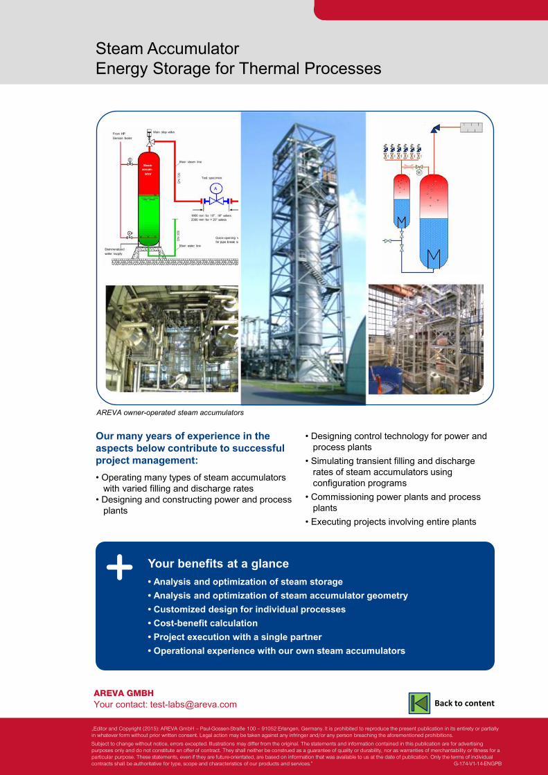
• Designing control technology for power and process plants • Simulating transient filling and discharge rates of steam accumulators using configuration programs • Commissioning power plants and process plants • Executing projects involving entire plants
AREVA GMBH Your contact: [email protected]
Steam Accumulator Energy Storage for Thermal Processes
Your benefits at a glance • Analysis and optimization of steam storage • Analysis and optimization of steam accumulator geometry • Customized design for individual processes • Cost-benefit calculation • Project execution with a single partner • Operational experience with our own steam accumulators
AREVA owner-operated steam accumulators
Our many years of experience in the aspects below contribute to successful project management: • Operating many types of steam accumulators with varied filling and discharge rates • Designing and constructing power and process plants
„Editor and Copyright (2015): AREVA GmbH – Paul-Gossen-Straße 100 – 91052 Erlangen, Germany. It is prohibited to reproduce the present publication in its entirety or partially in whatever form without prior written consent. Legal action may be taken against any infringer and/or any person breaching the aforementioned prohibitions.
Subject to change without notice, errors excepted. Illustrations may differ from the original. The statements and information contained in this publication are for advertising purposes only and do not constitute an offer of contract. They shall neither be construed as a guarantee of quality or durability, nor as warranties of merchantability or fitness for a particular purpose. These statements, even if they are future-orientated, are based on information that was available to us at the date of publication. Only the terms of individual contracts shall be authoritative for type, scope and characteristics of our products and services.” G-174-V1-14-ENGPB
Back to content

Unit Conversion Table
Conversion between international system of units (SI units) and British or US system of units
Technical Center - Focus on Technology
Physical quantity
British or US system of units to SI units
SI units to British or US system of units
Acceleration 1 ft/s² = 0.30480 m/s² 1 m/s² = 3.28083985 ft/s²
Area 1 sq in 1 sq ft
1 sq yd 1sq mi
= 0.64516·10-3 m² = 0.09290304 m² = 0.83612736 m² = 2.589988·106 m²
1 m² 1 m² 1 m² 1 m²
= 1.550003·103 sq in = 10.76391 sq ft = 1.195990 sq yd = 0.3861022·10-6 sq mi
Density 1 lb/ft³ = 16.01846 kg/m³ 1 kg/m³ = 0.06242797 lb/ft³
Dynamic viscosity
1 lbf s/sqft = 47.88026 Ns/m² 1 Ns/m² = 20.88543·10-3 lbf s/sqft
Energy 1 hp hr 1 PSh 1 BTU 1 lbf-ft
= 2.684520·106 J
= 2.6477955·106 J
= 1055.056 J = 1.355818 J
1 J 1 J 1 J 1 J
= 372.5061·10-9 hp hr
= 377.6727·10-9 PSh
= 947.8171·10-6 BTU
= 737.5621·10-3 lbf-ft
Force 1 pdl 1 lbf = 1 lb wt
1 sh tn 1 l tn
= 138.2550·10-3 N = 4.448222 N = 8896.443 N = 9964.016 N
1 N 1 N 1 N 1 N
= 7.233014 pdl = 224.8089·10-3 lbf; lb wt = 112.4045·10-6 sh tn = 100.3611·10-6 l tn
Heat conductivity
1 BTU/(in h R) 1 BTU/(ft h R)
1 BTU/(yd h R)
= 20.76882 W/(mK) = 1.730735 W/(mK) = 576.9116·10-3 W/(mK)
1 W/(mK) 1 W/(mK) 1 W/(mK)
= 48.14911·10-3 BTU/(in h R) = 577.7893·10-3 BTU/(ft h R) = 1.73368 BTU/(yd h R)
Heat transfer coefficient
1 BTU/(sq in h R) 1 BTU/(sq ft h R)
1 BTU/(sq yd h R)
= 817.6699 W/(m² K) = 5.6782633 W/(m² K) = 630.9181·10-3 W/(m² K)
1 W/(m² K) 1 W/(m² K) 1 W/(m² K)
= 1.222987·10-3 BTU/(sq in h R) = 176.1102·10-3 BTU/(sq ft h R) = 1.584992 BTU/(sq yd h R)
Length 1 in 1 ft
1 yd 1 mi
= 25.4·10-3 m = 0.3048 m = 0.9144 m = 1609.344 m
1 m 1 m 1 m 1 m
= 39.37008 in = 3.280840 ft = 1.093613 yd = 0.6213712·10-3 mi
Mass (inertia) 1 lb 1 stone
1 quarter 1 long ton (Brit.)
1 short ton (USA)
= 0.45359247 kg = 6.3502932 kg = 12.700586 kg = 1,016.0469 kg = 907.18474 kg
1 kg 1 kg 1 kg 1 kg 1 kg
= 2.204623 lb = 157.47304·10-3 stone = 78.73652·10-3 quarter = 984.2065·10-6 long tons (Brit.) = 1.102311·10-3 short tons (USA)
Mass flow 1 lb/min 1 lb/min 1 lb/min
= 27.2155422 kg/h = 7.55987283·10-3 kg/s = 0.0272155422 t/h
1 kg/h 1 kg/s
1 t/h
= 0.036743710 lb/min = 132.277357 lb/min = 36.743710 lb/min
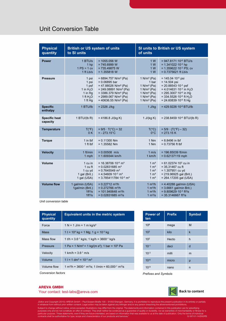
AREVA GMBH Your contact: [email protected]
Unit Conversion Table
Physical quantity
British or US system of units to SI units
SI units to British or US system of units
Power 1 BTU/s 1 hp
1 PS = 1 cv 1 ft Lb/s
= 1055.056 W = 745.6999 W = 735.49875 W = 1.355818 W
1 W 1 W 1 W 1 W
= 947.8171·10-6 BTU/s = 1.341022·10-3 hp = 1.359622·10-3 PS; cv = 0.7375621 ft Lb/s
Pressure 1 psi 1 psi 1 psf
1 in H2O 1 in Hg
1 ft H2O 1 ft Hg
= 6894.757 N/m² (Pa) = 0.06895 bar = 47.88026 N/m² (Pa) = 249.08891 N/m² (Pa) = 3386.379 N/m² (Pa) = 2989.067 N/m² (Pa) = 40636.55 N/m² (Pa)
1 N/m² (Pa) 1 bar
1 N/m² (Pa) 1 N/m² (Pa) 1 N/m² (Pa) 1 N/m² (Pa) 1 N/m² (Pa)
= 145.04·10-6 psi = 14.504 psi = 20.88543·10-3 psf = 4.014631·10-3 in H2O = 295.3007·10-6 in Hg = 334.5526·10-6 ft H2O = 24.60839·10-6 ft Hg
Specific enthalpy
1 BTU/lb = 2326 J/kg 1 J/kg = 429.9226·10-6 BTU/lb
Specific heat capacity
1 BTU/(lb R) = 4186.8 J/(kg K) 1 J/(kg K) = 238.8459·10-6 BTU/(lb R)
Temperature T(°F) 0 K
= 9/5 · T(°C) + 32 = - 273.15°C
T(°C) 0°C
= 5/9 · (T(°F) – 32) = 273.15 K
Torque 1 in lbf 1 ft lbf
= 0.11300 Nm = 1.35582 Nm
1 Nm 1 Nm
= 8.8496 in lbf = 0.73756 ft lbf
Velocity 1 ft/min 1 mph
= 0.00508 m/s = 1.609344 km/h
1 m/s 1 km/h
= 196.85039 ft/min = 0.62137119 mph
Volume 1 cu in 1 cu ft
1 cu yd 1 gal (Brit.) 1 gal (USA)
= 16.38706·10-6 m³ = 0.02831685 m³ = 0.7645549 m³ = 4.54609·10-3 m³ = 3.785411784·10-3 m³
1 m³ 1 m³ 1 m³ 1 m³ 1 m³
= 61.02374·103 cu in = 35,31467 cu ft = 1.307951 cu yd = 219.96925 gal (Brit.) = 264.17205 gal (USA)
Volume flow 1 gal/min (USA) 1gal/min (Brit.)
1ft³/s 1ft³/s
= 0.22712 m³/h = 0.272766 m³/h = 101.940648 m³/h = 0.02831685 m³/s
1 m³/h 1 m³/h 1 m³/h 1 m³/s
= 4.40288 gal/min (USA) = 3.6661 gal/min Brit.) = 9.809629·10-3 ft³/s = 35.3146667 ft³/s
Physical quantity
Equivalent units in the metric system
Force 1 N = 1 J/m = 1 m kg/s²
Mass 1 t = 10³ kg = 1 Mg; 1 g = 10-3 kg
Mass flow 1 t/h = 3.6-1 kg/s; 1 kg/h = 3600-1 kg/s
Pressure 1 Pa = 1 N/m² = 1 kg/(m s²); 1 bar = 105 Pa
Velocity 1 km/h = 3.6-1 m/s
Volume 1 l = 1 dm³ = 10-3 m³
Volume flow 1 m³/h = 3600-1 m³/s; 1 l/min = 60,000-1 m³/s
Power of ten
Prefix Symbol
106 mega M
103 kilo k
102 Hecto h
10-1 deci d
10-3 milli m
10-6 micro µ
10-9 nano n
Conversion factors Prefixes and Symbols
Unit conversion table
„Editor and Copyright (2015): AREVA GmbH – Paul-Gossen-Straße 100 – 91052 Erlangen, Germany. It is prohibited to reproduce the present publication in its entirety or partially in whatever form without prior written consent. Legal action may be taken against any infringer and/or any person breaching the aforementioned prohibitions.
Subject to change without notice, errors excepted. Illustrations may differ from the original. The statements and information contained in this publication are for advertising purposes only and do not constitute an offer of contract. They shall neither be construed as a guarantee of quality or durability, nor as warranties of merchantability or fitness for a particular purpose. These statements, even if they are future-orientated, are based on information that was available to us at the date of publication. Only the terms of individual contracts shall be authoritative for type, scope and characteristics of our products and services.” G-187-V1-14-ENGPB
Back to content
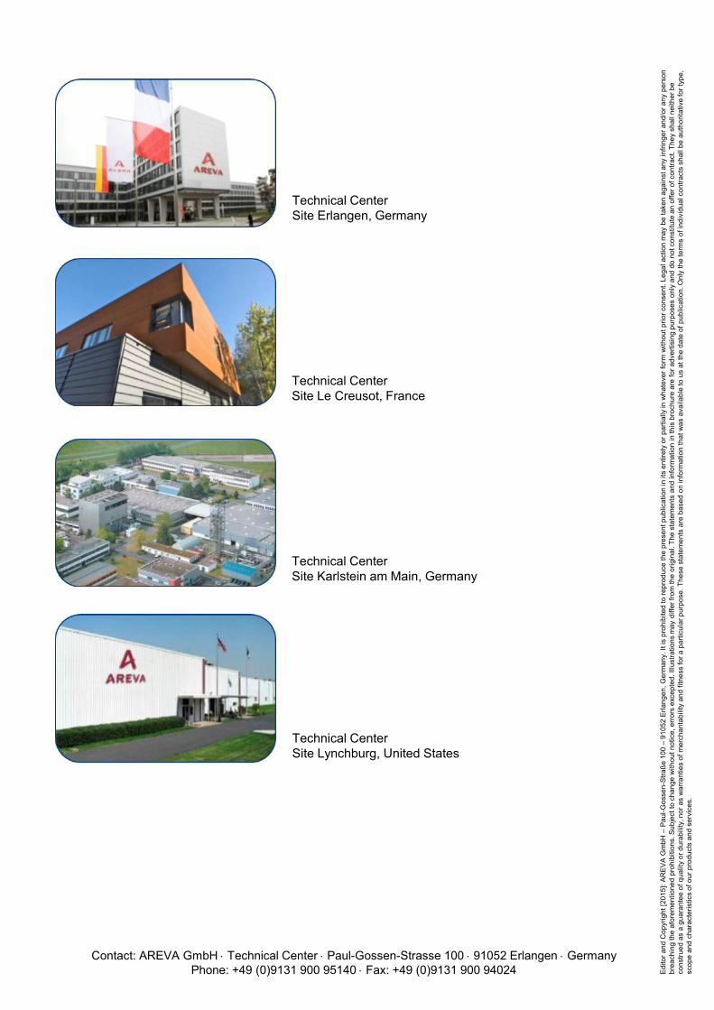
Technical Center Site Erlangen, Germany
Technical Center Site Le Creusot, France
Technical Center Site Karlstein am Main, Germany
Technical Center Site Lynchburg, United States
Contact: AREVA GmbH ⋅ Technical Center ⋅ Paul-Gossen-Strasse 100 ⋅ 91052 Erlangen ⋅ Germany Phone: +49 (0)9131 900 95140 ⋅ Fax: +49 (0)9131 900 94024 Ed
itor a
nd C
opyr
ight
[201
5]: A
REV
A G
mbH
– P
aul-G
osse
n-St
raße
100
– 9
1052
Erla
ngen
, Ger
man
y. It
is p
rohi
bite
d to
repr
oduc
e th
e pr
esen
t pub
licat
ion
in it
s en
tiret
y or
par
tially
in w
hate
ver f
orm
with
out p
rior c
onse
nt. L
egal
act
ion
may
be
take
n ag
ains
t any
infri
nger
and
/or a
ny p
erso
n br
each
ing
the
afor
emen
tione
d pr
ohib
ition
s. S
ubje
ct to
cha
nge
with
out n
otic
e, e
rror
s ex
cept
ed. I
llust
ratio
ns m
ay d
iffer
from
the
orig
inal
. The
sta
tem
ents
and
info
rmat
ion
in th
is b
roch
ure
are
for a
dver
tisin
g pu
rpos
es o
nly
and
do n
ot c
onst
itute
an
offe
r of c
ontra
ct. T
hey
shal
l nei
ther
be
cons
trued
as
a gu
aran
tee
of q
ualit
y or
dur
abili
ty, n
or a
s w
arra
ntie
s of
mer
chan
tabi
lity
and
fitne
ss fo
r a p
artic
ular
pur
pose
. The
se s
tate
men
ts a
re b
ased
on
info
rmat
ion
that
was
ava
ilabl
e to
us
at th
e da
te o
f pub
licat
ion.
Onl
y th
e te
rms
of in
divi
dual
con
tract
s sh
all b
e au
thor
itativ
e fo
r typ
e,
scop
e an
d ch
arac
teris
tics
of o
ur p
rodu
cts
and
serv
ices
.