Embed Size (px)
Citation preview

Focusing of beams into subwavelength area in aninhomogeneous medium
N.I. Petrov
Storage Lab., Samsung Advanced Institute of Technology,416, Maetan-3Dong, Paldal-Gu, Suwon City, Kyungki-Do, Korea
Abstract: Propagation and focusing of nonparaxial Gaussian beams withspherical wavefront in a graded-index medium are investigated usingquantum-theoretical method of coherent states. Explicit expressions for thetrajectory and width of a beam taking into account all correction terms to theparaxial approximation have been obtained. Electromagnetic fielddistributions in longitudinal and lateral directions are simulated. Diffraction ofstrongly focused high-aperture wave beams is investigated theoretically. Theratio of intensities of evanescent and propagating fields is calculated fordifferent values of focused spot.2001 Optical Society of AmericaOCIS codes: (350.5500) Propagation; (230.7370) Waveguides
References and links
1. H. Kogelnik, “On the propagation of Gaussian beams of light through lenslike media including those witha loss and gain variation,” Appl. Opt. 4, 1562 (1965).
2. L. W. Casperson, “Gaussian light beams in inhomogeneous media,” Appl. Opt. 12, 2434 (1973).3. D. D. Lowental, “Far-field diffraction patterns for Gaussian beams in the presence of small spherical
aberrations,” J. Opt. Soc. Am. 65, 853 (1975).4. L. W. Casperson, “Synthesis of Gaussian beam optical systems,” Appl. Opt. 20, 2243 (1981).5. S. A. Self, “Focusing of spherical Gaussian beams,” Appl. Opt. 22, 658 (1983).6. R. M. Herman, J. Pardo and T.A. Wiggins, “Diffraction and focusing of Gaussian beams,” Appl. Opt. 24,
1346 (1985).7. A. Kujawski, “Focusing of Gaussian beams described in terms of complex rays,” Appl. Opt. 28, 2458
(1989).8. A. R. Al-Rashed and B. E. A. Saleh, “Decentered Gaussian beams,” Appl. Opt. 34, 6819 (1995).9. M. Lax, W. H. Luisell, and W. B. McKnight, “From Maxwell to paraxial wave optics,” Phys. Rev. 11,
1365 (1975).10. G. P. Agrawal and D. N. Pattanayak, “Gaussian beam propagation beyond the paraxial approximation,” J.
Opt. Soc. Am. 69, 575 (1979).11. T. Takenaka, M. Yokota and O. Fukumitsu, “Propagation of light beams beyond the paraxial
approximation,” J. Opt. Soc. Am. A 2, 826 (1985).12. G. P. Agrawal and M. Lax, “Free-space wave propagation beyond the paraxial approximation,” Phys. Rev.
A 27, 1693 (1983).13. S. Nemoto, “Nonparaxial Gaussian beams,” Appl. Opt. 29, 1940 (1990).14. Q. Cao and X. Deng, “Corrections to the paraxial approximation of an arbitrary free-propagation beam,” J.
Opt. Soc. Am. A 15, 1144 (1998).15. A. Wunsche, “Transition from the paraxial approximation to exact solutions of the wave equation and
application to Gaussian beams,” J. Opt. Soc. Am. A 9, 765 (1992).16. X. D. Zeng, C. H. Liang and Y. Y. An, “Far-firld radiation of planar Gaussian sources and comparison
with solutions based on the parabolic approximation,” Appl. Opt. 36, 2042 (1997).17. H. Laabs, “Propagation of Hermite-Gaussian-beams beyond the paraxial approximation,” Optics
Commun. 147, 1 (1998).18. C. J. R. Sheppard and S. Saghafi, “Electromagnetic Gaussian beams beyond the paraxial approximation,”
J. Opt. Soc. Am. A 16, 1381 (1999).19. C. J. R. Sheppard, “High-aperture beams,” J. Opt. Soc. Am. A 18, 1579 (2001).20. Z. Ulanowski and I. K. Ludlow, “Scalar field of nonparaxial Gaussian beams,” Optics Letters 25, 1792
(2000).
(C) 2001 OSA 3 December 2001 / Vol. 9, No. 12 / OPTICS EXPRESS 658#37311 - $15.00 US Received October 18, 2001; Revised November 30, 2001

21. R. Borghi, M. Santarsiero and M. A. Porras, “Nonparaxial Bessel-Gauss beams,” J. Opt. Soc. Am. A 18,1618 (2001).
22. L. W. Casperson, “Beam propagation in periodic quadratic-index waveguides,” Appl. Opt. 24, 4395(1985).
23. J. N. McMullin, “The ABCD matrix in arbitrarily quadratic-index waveguides,” Appl. Opt. 25, 2184(1986).
24. D. Bertilone and C. Pask, “Exact ray paths in a graded-index taper,” Appl. Opt. 26, 1189 (1987).25. D. Bertilone, A. Ankiewicz and C. Pask, “Wave propagation in a graded-index taper,” Appl. Opt. 26, 2213
(1987).26. J. N. McMullin, “The ABCD matrix in graded-index tapers used for beam expansion and compression,”
Appl. Opt. 28, 1298 (1989).27. A. A. Tovar and L. W. Casperson, “Beam propagation in parabolically tapered graded-index waveguides,”
Appl. Opt. 33, 7733 (1994).28. J. Linares and C. Gomez-Reino, “Arbitrary single-mode coupling by tapered and nontapered GRIN fiber
lenses,” Appl. Opt. 29, 4003 (1990).29. S. G. Krivoshlykov and E. G. Sauter, “Propagation and focusing of nonparaxial Gaussian beams with
spherical wave fronts in graded-index waveguides with polynomial profiles,” J. Opt. Soc. Am. A 10, 262(1993).
30. N. I. Petrov, “Candidate’s Thesis in Physico-Mathematical Sciences” (Moscow: General Physics Institute,Russian Academy of Sciences, 1985).
31. N. I. Petrov, “Nonparaxial focusing of wave beams in a graded-index medium,” Rus. J. QuantumElectronics 29, 249 (1999).
32. D. Marcuse, Light transmission optics (Van Nostrand, New York, 1972).33. J. A. Arnaud, Beam and fiber optics (Academic Press, New York, 1976).34. R. J. Glauber, “Coherent and incoherent states of the radiation field,” Phys. Rev. 131, 2766 (1963).35. E. Schrodinger, Naturwissenschaften, 14, 664 (1926).36. S. G. Krivoshlykov, N. I. Petrov and I. N. Sisakyan, “Correlated coherent states and propagation of
arbitrary gaussian beams in graded-index media with loss and gain,” Sov. J. Quantum Electronics 7, 1424(1986).
37. H. A. Eide and J. J. Stamnes, “Exact and approximate solutions for focusing of two-dimensional waves,”J. Opt. Soc. Am. A 15, 1292 (1998).
38. Q. Wu, R. D. Grober, D. Gammon, D. S. Katzer, “Imaging Spectroscopy of Two-Dimensional Excitons ina Narrow GaAs/AlGaAs Quantum Well,” Phys. Rev. Letts. 83, 2652 (1999).
39. G. von Freymann, et.al., “Computer simulations on near-field scanning optical microscopy: Cansubwavelength resolution be obtained using uncoated optical fiber probes?,” Appl. Phys. Letts. 73, 1170(1998).
40. E. A. J. Marcatili, “Dielectric tapers with curved axes and no loss,” IEEE J. Quant. Electr. QE-21, 307(1985).
41. D. Bertilone, “Ray propagation and compression in a strictly adiabatic taper,” Opt. Quant. Electr. 19, 361(1987).
42. D. Bertilone, J. Love and C. Pask, “Splicing of optical waveguides with lossless graded-index tapers,”Opt. Quant. Electr. 20, 501 (1988).
43. L. D. Landau and E. M. Lifschitz, Quantum Mechanics (Pergamon, Oxford, 1965).44. N. I. Petrov, “Depolarization of light in a graded-index isotropic medium,” J. Mod. Opt. 43, 2239 (1996).45. N. I. Petrov, “Evolution of Berry's phase in a graded-index medium,” Phys. Letts. A 234, 239 (1997).46. S. Quabis, R. Dorn, M. Eberler, O. Glockl, G. Leuchs, “Focusing light to a tighter spot,” Opt. Comms.
179, 1 (2000).
1. Introduction
Light beams focused into a subwavelength area are of considerable interest owing to theirapplications in various fields such as microscopy, lasers, optical information storage, andoptical trapping. Analyses considering different aspects of Gaussian light beams including thefocusing have been in the literature for many years [1-8]. The propagation properties of such abeam are generally studied in the paraxial approximation. However for a strongly focusedbeam when the spot size of the beam is less than the wavelength it is necessary to go beyondthe paraxial approximation.
It is well known, that Gaussian beam changes its form at the focusing into asubwavelength area due to the effects of nonparaxiality. Various methods for consideration ofnonparaxial propagation of light beams have been proposed. In [9] the expansion procedure ofthe electric field into a power series in terms of small parameter was introduced. Many papers
(C) 2001 OSA 3 December 2001 / Vol. 9, No. 12 / OPTICS EXPRESS 659#37311 - $15.00 US Received October 18, 2001; Revised November 30, 2001

were devoted to nonparaxial corrections of fundamental and higher-order Gaussian beams[10-17]. The angular spectrum approach was used in [10] to obtain an exact solution for theelectromagnetic field. In [11] non-paraxial propagation of Laguerre-Gaussian and Hermite-Gaussian beams was investigated by the expansion theory introduced in [9]. In [17] allnonparaxial corrections for standard Hermite-Gaussian beams were evaluated. Anotherapproaches were proposed and used for investigation of high-aperture beams free-spacepropagation based on the complex-source-sink solution of Maxwell equations in [18, 19].Similar solutions for the scalar field of strongly focused Gaussian beams are given in [20]. In[21] all nonparaxial corrections for coherent Bessel-Gauss beams are obtained usingformalism suggested by Wunsche [15].
Analytical methods may also be developed for investigation of paraxial light beamspropagation in an inhomogeneous medium [22-28]. The ABCD matrix approach for beamexpansion and compression analysis in quadratic-index waveguides was developed in papers[23, 26]. Note, that in paraxial approximation the shape of the Gaussian beam is preservedafter passing through the graded-index waveguide, even if the beam is decentered [8].
A quantum-theoretical method of coherent states was used in [29, 30] for consideration ofbeam propagation in a graded-index medium beyond the paraxial approximation. The firstorder corrections were obtained using this method. In [31] the explicit expressions for thebeam trajectory and width were obtained and mode structure forming in a graded-indexwaveguide have been investigated.
Note that the number of corrections must be increased as the beam divergence anglegrows, in other case such models became inaccurate. Besides the nonparaxial effects areaccumulated with distance, so the small corrections became significant at long distances.Below we will show, that the revival effect of the beam trajectory at long distances predictedin [29] is not physical, but is only the result of the use of the expression which is not valid forthese distances. Therefore the developing of explicit methods for consideration of nonparaxialpropagation is much interesting.
In this paper we present a rigorous description of the propagation and focusing of aGaussian beams with spherical wavefront in a graded-index medium using the quantum-theoretical method of generalized coherent states which allows us to calculate the averagevalues with the help of an operator approach. The whole dynamics of the system is transferredto the operators in this approach. This allows us to investigate the evolution of thecharacteristics of the propagating beam with the help of pure algebraic procedures, that iswithout using explicit expressions for field wavefunctions and without the calculation of anyintegrals. The concept of choice of the quantum formalism in the waveguide theory is thefollowing. It is well known that the Maxwell equations for the scalar wave paraxial beamsmay be reduced with high accuracy to a parabolic type equation. This approximation enablesus to use well-developed quantum-mechanical methods for the investigation of wavepropagation in inhomogeneous media, because the parabolic equation formally coincides withthe Schrodinger equation in quantum mechanics for particles moving in a time-dependentpotential well. All that is required is to redefine the parameters in the Schrodinger equation.The role of time is now taken by the longitudinal coordinate, and Planck’s constant issuperseded by the radiation wavelength in vacuum. The potential is defined as a function ofthe refractive index of the medium. The intimate relationship between the wave mechanics ofparticles and the optics of light beams has been discussed in detail in many papers (see, e.g.,[32, 33]).
2. Formulation of the problem
The equation describing the propagation of radiation in an inhomogeneous medium from
the Maxwell equations for the electric field )exp( tiE ν−r
may be obtained as
(C) 2001 OSA 3 December 2001 / Vol. 9, No. 12 / OPTICS EXPRESS 660#37311 - $15.00 US Received October 18, 2001; Revised November 30, 2001

( ) 0ln 222 =∇⋅∇++∆ nEEnkErrrrr
, (1)
where k=2π/λ is the wave number, n(x,y,z) is the refractive index of the medium.
In the case of slowly inhomogeneous media ( ( ) 1/2/ 22 <<∇ nnπλ ) the third termcorresponding to the polarization is small and the electric field is described by the Helmholtzequation:
0),,(222
2
2
2
2
2
=+++ Ezyxnkz
E
y
E
x
E
∂∂
∂∂
∂∂
(2)
If the medium is homogeneous in the longitudinal direction z, equation (2) may bereduced to the equivalent Schrodinger equation for the reduced field ψ(x,y):
),(),(ˆ yxyxH εψψ = , (3)
where ε and ψ(x, y) are the eigenvalue and the eigenfunction of the Hamiltonian
( )( )yxnnyxk
H ,2
1
2
1ˆ 2202
2
2
2
2−+
+−=∂∂
∂∂
. (4)
The evolution of the field
),()exp(),,( yxzizyxE ψβ=
is determined by the propagation constant
21
20
02
1)(
−=
nkn
εεβ .
The evolution of any operator acting on the solution of Eqn (2) is specified by an equationanalogous to the Heisenberg equation:
[ ]β,ˆˆ AiA =&
, (5)
where dzAdA /ˆˆ =&
; [ ] AAA ˆˆˆˆˆ,ˆ βββ −= is the commutator of the operators A and β .The propagation-constant operator assumes the form
21
20
0
ˆ21ˆ
−=
n
Hknβ ,
and its eigenvalues determine the propagation constants β(ε).The evolution operator for the field has the form )ˆexp(ˆ ziU β= , and the evolution of any
operator A is given by UAUzA ˆˆˆ)(ˆ += .
(C) 2001 OSA 3 December 2001 / Vol. 9, No. 12 / OPTICS EXPRESS 661#37311 - $15.00 US Received October 18, 2001; Revised November 30, 2001
Thus, the solution of the Helmholtz equation (2) reduces in this instance to the solution ofthe Heisenberg equation for operators the average values of which determine the parametersof the investigated beam, for example, the coordinate of its gravity center and its width.
Consider the propagation of radiation in a medium homogeneous in the direction z with aparabolic variation of the refractive index in the transverse directions x and y:
)( 22220
2 yxnn +−= ω , (6)
where n0 is the refractive index along the axis and ω is the gradient parameter of the medium.The expression (6) describes the parabolic distribution of the refractive index of the medium,which is infinite in transverse directions. However the modes of the medium (6) as the modesof graded-index waveguide (fiber) may also be considered. This is valid as a firstapproximation for lowest-order waveguide modes when the waveguide carries a sufficientlylarge number of modes.
Consider an incident beam in the form of coherent states which are Gaussian wavepackets and represent the eigenfunctions of the annihilation operator a :
212,1212,1ˆ ααααα =a ,
+= xp
kixka ˆˆ
2
1ˆ1 ωω ,
+= yp
kiyka ˆˆ
2
1ˆ2 ωω ,
xk
ip x ∂
∂−=ˆ ,yk
ip y ∂
∂−=ˆ .
The wavefunction 21αα defines the space distribution of the electric field and has
the form
( ) ( )
( )
+++−
+++−
=2
22
122
21
2122
2
1
21
2
1
22exp
αααα
ααωω
πωαα
yxkyxk
k.
The complex eigenvalues
+= 001
2
1xp
kixkω
ωα and
+= 002
2
1yp
kiykω
ωα
determine the initial coordinates x0, y0 of the gravity center of the beam and the angle of itsinclination px0=n0sinϕx0, py0=n0sinϕy0 to the axis of the medium. The term “coherent states”was introduced by Glauber [34] for a one-dimensional steady-state quantum oscillator inconnection with problems in quantum optics. Such states were constructed and investigatedalready by Schrodinger [35] in order to establish a relationship between the classical andquantum approaches.
In the paraxial approximation, when only the first term in the expansion series of the
propagation-constant function β in terms of 20/ˆ nH is considered,
⋅⋅⋅−−−−=
60
3
40
2
20
02
ˆ
2
ˆˆ1ˆ
n
H
n
H
n
Hknβ , (7)
(C) 2001 OSA 3 December 2001 / Vol. 9, No. 12 / OPTICS EXPRESS 662#37311 - $15.00 US Received October 18, 2001; Revised November 30, 2001

the coherent states have the minimum possible width and an angular diffraction divergence onpropagation in a medium the refractive index of which is defined by expression (6). Accordingto beam optics, the center of gravity of such wave packets moves along a geometrical path andthe packet width does not change during the propagation process. Furthermore, the coherentstates are the generating functions for the modes of the medium:
210, 21
212221
21
21
22
21
!!mm
mme
mm
mm
∑∞
=
−−=
αααα
αα
.
3. Evolution of the beam path and width
Consider the evolution of the beam path and width in a medium (6). For simplicity, weconfine ourselves to one component of the field. The beam path is found by calculating theaverage value of the coordinate operator:
( ) ( ) ( ) ( )0)(ˆ0)0(ˆˆˆ)0(ˆ)( αααα ψψψψψψ zxUxUzxzzx === + , (8)
where )(ˆ zx is found from the solution of the Heisenberg equation (5). The evolution of thewidth of the wave packet is found similarly:
222 ˆˆααα xxx −=∆ . (9)
In the paraxial approximation, the expression for the beam path has the following form:
( )θωα −= zxx cos0 ,
where θ is determined from the relationship θαα ie= . The beam width ωα kx 2/1=∆ is
not changed at the propagation in this approximation.When account was taken of the next term in expansion (7), the expression for the beam
path assumed the form [30]
−+
+
−= θωαωωωα
ω
αα z
knz
knnz
knkx
30
22
30
2
030
2sincos1cosexp
2
(10)
Substitution of the solution of eqn (5) for the coordinate operator in formula (8) andcalculation of the matrix elements gives the following expression for the coordinate of thecenter of gravity of the beam taking into account all terms of expansion (7):
∑∞
=
−
−
+−−
+−=0
20
20
0
2
2
321
2
121cos
!2
2
m
m
zmkn
mkn
knm
ek
x θωωαωα α
α (11)
The evolution of the wave-packet width is described by the expression
(C) 2001 OSA 3 December 2001 / Vol. 9, No. 12 / OPTICS EXPRESS 663#37311 - $15.00 US Received October 18, 2001; Revised November 30, 2001

2
020
20
0
22
2
2
22
521
2
121cos
!2
21
2
12
α
ααθωωα
α
α
ω
x
zmkn
mkn
knm
ekx
m
m
−
−
+−−
+−
++
=∆∑∞
=
−
(12)
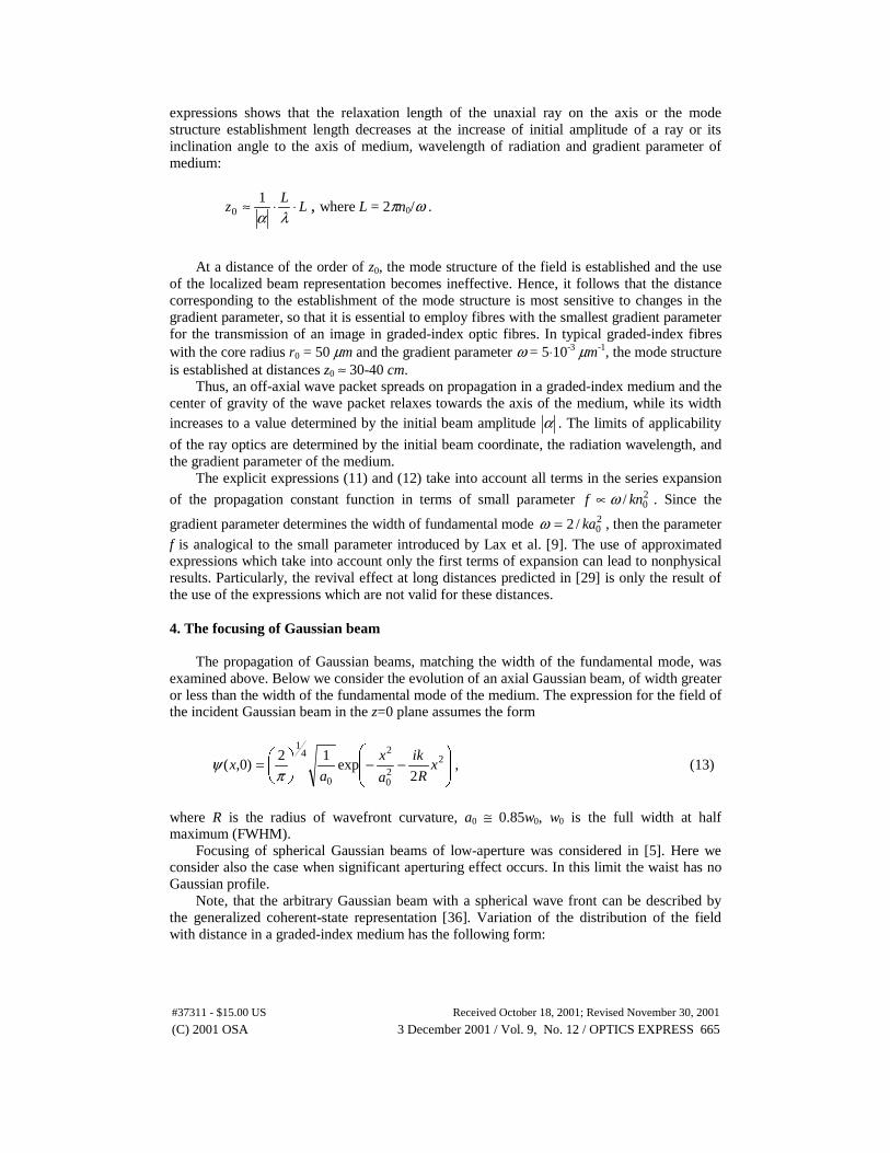
We may note that, in contrast to the paraxial approximation, the trajectory of gravitycenter of wave beam depends on the radiation wavelength and differs from the trajectory ofgeometrical ray. Moreover the amplitude of the trajectory decreases with distance (Fig.1), i.e.the sum of periodical functions gives the damping oscillations though there are no energylosses at propagation. Beams with the small initial inclination angle (Fig.1a) or small axisdisplacement (Fig.1b) have almost periodical trajectories and invariable diameters up tosufficient distances. It means that paraxial approximation may be used successfully in thesecases. For large inclination angles and axis displacements visible deviations from paraxialapproximation are appeared already at short distances.
0 100 200 300 400 500
-30
-20
-10
0
10
20
30a)
∆xα
x,µm
z, µm
0 100 200 300 400 500-30
-20
-10
0
10
20
30b)
<x>α
x,µm
z, µm
Fig. 1. Trajectories of wave beams (dashed curves) of wavelength λ = 0.65 µm accompanied byits width (solid curves) for gradient parameter ω = 5⋅10-2 µm-1 with initial inclination angles 15°and 60° (a) and initial axis displacements 7.76 and 26 µm (b).
The expressions (11) and (12) are the exact solutions including all correction terms to theparaxial solution and were obtained to our knowledge in the first time. Analysis of these
(C) 2001 OSA 3 December 2001 / Vol. 9, No. 12 / OPTICS EXPRESS 664#37311 - $15.00 US Received October 18, 2001; Revised November 30, 2001
expressions shows that the relaxation length of the unaxial ray on the axis or the modestructure establishment length decreases at the increase of initial amplitude of a ray or itsinclination angle to the axis of medium, wavelength of radiation and gradient parameter ofmedium:
LL
z ⋅⋅≈λα
10 , where L = 2πn0/ω .
At a distance of the order of z0, the mode structure of the field is established and the useof the localized beam representation becomes ineffective. Hence, it follows that the distancecorresponding to the establishment of the mode structure is most sensitive to changes in thegradient parameter, so that it is essential to employ fibres with the smallest gradient parameterfor the transmission of an image in graded-index optic fibres. In typical graded-index fibreswith the core radius r0 = 50 µm and the gradient parameter ω = 5⋅10-3 µm-1, the mode structureis established at distances z0 ≈ 30-40 cm.
Thus, an off-axial wave packet spreads on propagation in a graded-index medium and thecenter of gravity of the wave packet relaxes towards the axis of the medium, while its widthincreases to a value determined by the initial beam amplitude α . The limits of applicability
of the ray optics are determined by the initial beam coordinate, the radiation wavelength, andthe gradient parameter of the medium.
The explicit expressions (11) and (12) take into account all terms in the series expansion
of the propagation constant function in terms of small parameter 20/ knf ω∝ . Since the
gradient parameter determines the width of fundamental mode 20/2 ka=ω , then the parameter
f is analogical to the small parameter introduced by Lax et al. [9]. The use of approximatedexpressions which take into account only the first terms of expansion can lead to nonphysicalresults. Particularly, the revival effect at long distances predicted in [29] is only the result ofthe use of the expressions which are not valid for these distances.
4. The focusing of Gaussian beam
The propagation of Gaussian beams, matching the width of the fundamental mode, wasexamined above. Below we consider the evolution of an axial Gaussian beam, of width greateror less than the width of the fundamental mode of the medium. The expression for the field ofthe incident Gaussian beam in the z=0 plane assumes the form
−−
= 220
2
0
41
2exp
12)0,( x
R
ik
a
x
ax
πψ , (13)
where R is the radius of wavefront curvature, a0 ≅ 0.85w0, w0 is the full width at halfmaximum (FWHM).
Focusing of spherical Gaussian beams of low-aperture was considered in [5]. Here weconsider also the case when significant aperturing effect occurs. In this limit the waist has noGaussian profile.
Note, that the arbitrary Gaussian beam with a spherical wave front can be described bythe generalized coherent-state representation [36]. Variation of the distribution of the fieldwith distance in a graded-index medium has the following form:
(C) 2001 OSA 3 December 2001 / Vol. 9, No. 12 / OPTICS EXPRESS 665#37311 - $15.00 US Received October 18, 2001; Revised November 30, 2001

∑=
−−
−
=ΨN
m
zim
m
mm mekxH
u
v
m
H
uvu
vux
kkzx
0
2
2
41
24
1
)(22!
)0(1
**2exp),( βωω
πω
, (14)
where ( ) ϕiir evvv 2
122 += , ( ) 2
1coscos
1
2
1 −
−= χµχωµ
ωrv ,
( ) 21
cossin2
1 −= χµχωµiv , ( ) ϑiir euuu 2
122 += ,
( ) 21
coscos1
2
1 −
+= χµχωµ
ωru , ( ) 21
cossin2
1 −= χµχωµiu
−=
r
i
v
varctanϕ ,
=
r
i
u
uarctanϑ ,
−=
R
ka
2arctan
20χ , χµ sinR−= ,
21
20
0 2
121
+−= mkn
knmωβ .
Here N is the maximum number of propagating modes determined by the
relationship .2/12/20 −≤ ωknN
The beam width evolution is described by the expression
( ) ( )[ ]
+−−
+
++
=∆+
∞
=
+∑ ϑϕββω zu
v
m
HH
u
vv
v
kzx
mmm
m
mmir222
0
2
2222
22
2
20
cos2!2
)0()0(
21
2
1)( (15)
For beams with initially planar wave fronts χ=0 and 202
1ka=µ . When account is taken
in expansion (7) only of the terms quadratic in the Hamiltonian, the beam width is describedby the expression
++
−+−+=∆
−
zknn
zknu
v
u
v
u
vv
kzx
30
2
0
43
30
2
2
2
4
4
222
032
2
3cos
4cos21
221
2
1)(
ωωφωω
,
where
−
= z
knu
vz
knu
v30
2
2
2
30
2
2
2 4cos1
4sinarctan
ωωφ .
The minimum beam width is attained at a distance
(C) 2001 OSA 3 December 2001 / Vol. 9, No. 12 / OPTICS EXPRESS 666#37311 - $15.00 US Received October 18, 2001; Revised November 30, 2001

++≅
20
20
2
240
2
04
8
312
ank
aknL f
ωωπ , (16)
i.e. the length of graded-index lens depends on the parameters of incident beam.In the paraxial approximation, expression (15) has the form
−+=∆ z
nuvv
kx
0
220
2cos221
2
1 ωω
.
The minimum beam width is attained in this approximation at a distance ωπ 2/0nz =and is determined by the expression:
20
222min
1
akx
ω=∆ .
In the case of paraxial approximation the focusing distance in graded-index mediumdepends only on the parameters of medium. When account is taken of nonparaxiality, thefocusing distance (16) depends also on the parameters of radiation. The focusing distance orthe graded-index lens length for nonparaxial beam is less than the focusing distance forparaxial beam.
The distribution of the field intensity2
),(),( zxzxI ψ= may be found from formula
(14). We may note that the total energy is normalized with respect to unity ∫ == 1),( dxzxIP
and remains constant for all values of z. Fig.2 represents the distribution of the field intensityalong the axial line of the medium.
0 20 40 60 80 100 120 140 160 180 2000
5
10
15
20
25
30
35
I(0,
z)/I(
0,0)
z, µm
Fig. 2. Variation with distance of the field intensity along the axial line of a graded-index mediumwith ω=5⋅10-2 µm-1 and n0=1.5; half-width of the incident beam a0 = 15 µm.
The field intensity in the focal plane zf = 44.9 µm increases by a factor of 30 comparedwith the intensity in the initial plane. The focal planes of nonparaxial and paraxial beams,where the highest intensity on the axis and smallest waist of the beam are attained, are not thesame. The focusing distance for nonparaxial beam is shorter than for paraxial beam. There is asignificant difference in the intensity distribution along the medium axis at the front of focusand behind it. This asymmetry is caused by the effect of nonparaxiality. Note, that theseeffects have also been shown to appear for a free-space beam focusing [37]. Fig.3 presents the
(C) 2001 OSA 3 December 2001 / Vol. 9, No. 12 / OPTICS EXPRESS 667#37311 - $15.00 US Received October 18, 2001; Revised November 30, 2001

distributions of the field intensity in the transverse plane. As can seen from Fig.3, thedistributions of the field intensity differ significantly from the initial Gaussian distribution.
Note that taking into account only guided modes we obtain usual classical value forminimal spot size determined by the diffraction limit (amin≈λ/2n).
-40 -20 0 20 400.00
0.01
0.02
0.03
0.04
0.05
0.06
a)I(
x)
x, µm
-6 -4 -2 0 2 4 60.0
0.1
0.2
0.3
0.4
0.5
b)
I(x)
x,µm
-6 -4 -2 0 2 4 60 .0
0 .5
1 .0
1 .5
2 .0
c)
I(x)
x ,µm
Fig. 3. Distribution of the field intensity in a transverse plane of a waveguide at various distancesfrom the initial plane z=0 (a), z = 40 (b) and z = 44.9 µm (c) (the parameters of the beam and themedium correspond to those in Fig.2).
(C) 2001 OSA 3 December 2001 / Vol. 9, No. 12 / OPTICS EXPRESS 668#37311 - $15.00 US Received October 18, 2001; Revised November 30, 2001

5. Diffraction of strongly focused Gaussian beam
It is well known that when focusing light onto a small object then this object may lead to anenergy concentration below the diffraction limit due to the presence of evanescent waves.Below we consider the strongly focused spot of subwavelength size at initial plane z=0. Theelectric field of such spot may be represented as the sum of propagating and evanescentmodes: E = Ep + Eev. In near-field zone the contribution of evanescent modes may becomesignificant to compare with propagating modes. Inversely, in far-field zone only thepropagating modes may be considered.
The evanescent fields become visible if the spots beyond the diffraction limit areconsidered. In Fig.4 the distributions of the evanescent and propagating fields are presentedfor the Gaussian beam of the width a0 = 50 nm in a graded-index medium with n0 = 1.5 and ω= 10-2 µm-1. The intensity of evanescent field on the axis in 2.4 times greater than the intensityof the propagating field. The amplitude of evanescent field on the axis increases with thedecrease of beam width, whereas the amplitude of propagating field decreases. The regionwhere the evanescent field dominates is only within a fraction of the wavelength of the lightfrom the initial plane, i.e. in near-field zone.
-2 -1 0 1 2
-1
0
1
2
3
Ep
E e v
E
x , µm
Fig. 4. Distribution of the evanescent (red curve) and propagating (blue curve) fields in atransverse direction at the initial plane.
Note, that the oscillations in lateral parts of propagating and evanescent fields (Fig.4) take
place in anti-phase to each other, so the total intensity2
evp EEI += distribution has not any
oscillating tails (Fig.5).
(C) 2001 OSA 3 December 2001 / Vol. 9, No. 12 / OPTICS EXPRESS 669#37311 - $15.00 US Received October 18, 2001; Revised November 30, 2001

-1 .0 -0.5 0.0 0.5 1.00
5
10
15
I
x, µm
Fig. 5. Distribution of the total field intensity at the initial plane.
In far-field zone the evanescent fields do not contribute to the total field, so thepropagating modes may only be considered. Distribution of propagating field does not have atruly Gaussian profile (Fig.6) owing to the absence of evanescent field at far-field zone.
-1 .0 -0 .5 0 .0 0.5 1 .00.0
0.5
1.0
1.5
2.0
2.5
I p
x , µm
Fig. 6. Distribution of the propagating field intensity at the initial plane.
The ratio of energy guided by propagating modes to the total input energy η = Pg/P0 israpidly decreased if the focused spot became less than the value of λ/2n owing to increase ofevanescent part of energy (Fig.7). For a given aperture size the energy guided by propagatingmodes grows and energy of evanescent modes decreases if the refractive index of mediumincreases.
(C) 2001 OSA 3 December 2001 / Vol. 9, No. 12 / OPTICS EXPRESS 670#37311 - $15.00 US Received October 18, 2001; Revised November 30, 2001

0.0 0.1 0.2 0.30.0
0.2
0.4
0.6
0.8
1.0
3 2
1
32
1
Pg/
P0,
Pev
/P0
a0, µm
Fig. 7. The ratio of energy guided by propagating modes Pg (solid curves) and evanescent modesPev (dashed curves) to the total input energy P0 as function of spot size a0 for different values ofrefractive index: 1 – n0 = 1.5; 2 – n0 = 2; 3 – n0 = 3.87.
Beam width evolution with distance is investigated for different values of aperture size atinitial plane. Variation in the angle θ0 at which the far-field intensity drops to one half of theintensity on the axis is calculated for different values of the initial spot size. It is obtained, thatfor the Gaussian beam the maximum value of θ0 is about 37°. As is shown in [18] for theelectromagnetic mixed-dipole wave the maximum value of θ0 is 37.8°, which is practically thesame. It was obtained in [16], that the upper limit on the beam divergence angle is 65.5°,which is cannot be reached in our case. The maximum angle, where the intensity in atransverse plane in the far-field drops to 1/e of the on-axis value is 45° (Fig.8).
0.0 0 .1 0 .2 0 .3 0 .4
10
20
30
40
50
θ 1/2
θ 1/e
θ,de
gree
wa, µm
Fig. 8. Variation in the angle θ0 at which the far-field intensity drops to one half and 1/e of theintensity on the axis for different values of the initial spot size.
6. Discussion
It is known that the threshold for the maximum focusing of the light beam can beestimated from the uncertainty relationship
(C) 2001 OSA 3 December 2001 / Vol. 9, No. 12 / OPTICS EXPRESS 671#37311 - $15.00 US Received October 18, 2001; Revised November 30, 2001

20
2
2
222
164
1
npkx
πλ>>
∆≥∆ , (17)
where the angular divergence of the beam is 20
2 np <<∆ .The uncertainty relationship (17) is obtained for the beam width and divergence, which
are the averaged parameters. For beam focusing the electric field distribution is moreimportant. Calculations show that the significant part of incident beam power may be focusedinto the central spot with the subwavelength size beyond the diffraction limit. The recentexperimental and theoretical studies [38, 39] of near-field emission from uncoated taperedfiber probes prove that subwavelength resolution can be obtained. In [38] the λ/3 spatialresolution using solid immersion lens microscopy was obtained.
The relationship (17) corresponds to the beams with plane wave front. In the case ofbeams with spherical wave front one can be obtained the following uncertainty relationship[36]
222
42
4/1 kpx
xR
−∆∆∆≥ , (18)
and due to ∆p ≤ 1, 2/0min axR =∆≥ , i.e. the minimal value of radius of curvature is adiffraction limited. Note that R may be negative, that corresponds to the light sources with aconverging spherical wave front. Such a spherical wave front is formed, particularly, by thesolid immerse lens.
To diminish the spot size to subwavelength area the medium with high refractive indexmay be used. However such materials have a high absorption. Another method to decrease thespot size is to use the longitudinally inhomogeneous medium. Multimode graded-indexwaveguide tapers may be used as focusing or defocusing elements. Strictly adiabatic tapersthat do not radiate along their length are proposed and investigated in [40-42]. It was shownthat impractically long length of taper is often required.
Choosing the optimal change with distance z of gradient parameter ω(z) we can reducethe size of initial spot. The size of the focused spot may be decreased when series-distributedgraded-index lenses of length ii nz ωπ 2/0=∆ and with different gradient parameters
nωωω <<< ...21 are used. For example, the perfect matching between two waveguides with
different gradient parameters −= ωω )(z and += ωω )(z may be achieved if the transparent
barrier +−== ωωωω 0)(z with length of ),12)(2/( 00 += pnL ωπ p = 0, 1, 2, … (the
analog of the Ramsauer effect in quantum mechanics [43]) or the barrier
( )[ ]{ }02 /2sin21)( nzbaz −− ++= ωωω , where 1, <<ba , are used.
The size of the focused spot may be reduced by an increase of the gradient parameter ofthe medium. There is a cutoff value of the gradient parameter determining the possibility for
the propagation of the fundamental mode: .20max kn=ω At maxωω > only the evanescent
waves are possible. On the other hand, the width of the fundamental mode is determined by
the gradient parameter: )/(20 ωka = . Thus, for the minimal value of the beam width we
have: )/(2 0min kna = , i.e. FWHM w0 ≅ λ/4n0. However, the condition of a weak
inhomogeneity of the medium is infringed for high values of ω, which necessitates allowancefor the polarization effects, i.e. the vector wave equation (1) should be considered instead ofHelmholtz equation (2). These effects for paraxial beam in a graded-index medium wereconsidered by us on the basis of a treatment of coherent states [44, 45]. It was shown in [44],
(C) 2001 OSA 3 December 2001 / Vol. 9, No. 12 / OPTICS EXPRESS 672#37311 - $15.00 US Received October 18, 2001; Revised November 30, 2001

that the polarization is limiting factor to focus a light beam into a subwavelength spot.However, the radially polarized radiation may be used to avoid this limitation [46].
7. Summary
We have analyzed propagation and focusing of Gaussian beams in graded-index mediumbeyond the paraxial approximation.
The expressions for the beam trajectory and width taking into account all correction terms
of a series of expansion of powers of a small dimensionless parameter 20/ knf ω∝ are
obtained explicitly. Exact analytical expressions (11) and (12) for the trajectory and width ofdecentered Gaussian beams in graded-index medium were not obtained earlier to ourknowledge. It is obtained, that the gravity center drops on the axis of medium even thelossless medium is considered. It is shown, that the effect of the beam trajectory revivalpredicted earlier in [29], is not physical, but due to the use of approximated expression at largedistances where the validity of this approximation is disappeared.
The localized wave packets (coherent states), which have minimum width and angulardiffraction spreading during propagation in a medium with a quadratic index profile may beused for description of an off-axial Gaussian beams in paraxial approximation. The center ofgravity of such wave packets moves along a geometrical path, i.e. obeys geometrical opticsand the packet width does not change during the propagation process. In nonparaxial case thebeam center does not follow along a geometrical ray trajectory. The limits of applicability ofthe ray optics are determined by the initial beam coordinate, the radiation wavelength, and thegradient parameter of the medium.
Nonparaxiality causes a change of initially Gaussian profile at the propagation and to anasymmetric distribution of the field intensity in the longitudinal direction. The focal planes ofnonparaxial and paraxial beams are not the same. The focusing distance for nonparaxial beamis shorter than for paraxial beam.
Diffraction limited minimal value for radius of wavefront curvature of a spherical beamhas been determined from the uncertainty relation.
It is shown, that the nonparaxial focusing in longitudinally homogeneous graded-indexmedium and the paraxial focusing in longitudinally inhomogeneous medium give the sameminimal spot size limited by diffraction.
The minimal spot size using only the propagating modes is diffraction limited. Furtherdecrease of spot can be carried out if the evanescent modes are included. For a given aperturesize the energy guided by propagating modes grows and energy of evanescent modesdecreases if the refractive index of medium increases. So far as evanescent modes cannot beregistered at far-field zone, far-field image of the spot will be greater than the real spot size.
Far-field radiation of high-aperture Gaussian beam has not a truly Gaussian profile, buthas oscillating tails outside the central region. In near-field region these oscillations arecompensated by anti-phase oscillations of the same amplitude of evanescent field.
It is obtained, that for the Gaussian beam the maximum value of θ0 at which the far-fieldintensity drops to one half of the intensity on the axis approximately is 37°. The maximumangle, where the intensity in a transverse plane in the far-field drops to 1/e of the on-axis valueis 45°.
(C) 2001 OSA 3 December 2001 / Vol. 9, No. 12 / OPTICS EXPRESS 673#37311 - $15.00 US Received October 18, 2001; Revised November 30, 2001