Embed Size (px)
Citation preview

TRELLEBORG SEALING SOLUTIONS
YOUR PARTNER FOR SEALING TECHNOLOGY
PRODUCT CATALOG & ENGINEERING GUIDE
Food, Beverage & Pharmaceutical
Sealing Systems
3023_TTS_FBPCatalog_CMYK_A4_v1.2.indd 1 14.04.2014 15:30:43
Food, Beverage &
Pharm
aceutical Sealing S
ystems
© 2
01
5 T
relle
borg
Gro
up.
At t
ime
of p
ublic
atio
n th
e in
form
atio
n co
ntai
ned
in t
his
liter
atur
e is
bel
ieve
d to
be
corr
ect
and
accu
rate
.99G
BK
2B
RO
EE1216
www.Tss.Trelleborg.com
facebook.com/TrelleborgSealingSolutions
twitter.com/TrelleborgSeals
youtube.com/TrelleborgSeals
flickr.com/TrelleborgSealingSolutions
Trelleborg is a world leader in engineered polymer solutions that seal, damp and protect critical applications in demanding environments. Its innovative engineered solutions accelerate performance for customers in a sustainable way. The Trelleborg Group has local presence in over 40 countries around the world.

ISO 9001:2008 ISO/TS 16949:2009
Your Partner for Sealing Technology
Trelleborg Sealing Solutions is a major international developer, manufacturer and supplier of seals, bearings and molded components in polymers. We are uniquely placed to offer dedicated design and development from our market-leading product and material portfolio: a one-stop-shop providing the best in elastomer, silicone, thermoplastic, PTFE and composite technologies for applications in aerospace, industrial and automotive industries.
With 50 years of experience, Trelleborg Sealing Solutions engineers support customers with design, prototyping, production, test and installation using state-of-the-art design tools. An international network of over 70 facilities worldwide includes over 20 manu- facturing sites, strategically-positioned research and development centers, including materials and development laboratories and locations specializing in design and applications.
Developing and formulating materials in-house, we utilize the resource of our material database, including over 2,000
proprietary compounds and a range of unique products.Trelleborg Sealing Solutions ful�lls challenging service requirements, supplying standard parts in volume or a single custom-manufactured component, through our integrated logistical support, which effectively delivers over 40,000 sealing products to customers worldwide.
Facilities are certi�ed to ISO 9001:2008 and ISO/TS 16949:2009. Trelleborg Sealing Solutions is backed by the experience and resources of Trelleborg Group, one of the world’s foremost experts in polymer technology.
The information in this brochure is intended to be for general reference purposes only and is not intended to be a speci�c recommendation for any individual application.
The application limits for pressure, temperature, speed and media given are maximum values determined in laboratory conditions. In application, due to the interaction of operating
parameters, maximum values may not be achieved. It is vital therefore, that customers satisfy themselves as to the suitability of product and material for each of their individual
applications. Any reliance on information is therefore at the user‘s own risk. In no event will Trelleborg Sealing Solutions be liable for any loss, damage, claim or expense directly
or indirectly arising or resulting from the use of any information provided in this brochure. While every effort is made to ensure the accuracy of information contained herewith,
Trelleborg Sealing Solutions cannot warrant the accuracy or completeness of information.
To obtain the best recommendation for a specific application, contact your local Trelleborg Sealing Solutions marketing company.
This edition supersedes all previous brochures. This brochure or any part of it may not be reproduced without permission.
® All trademarks are the property of Trelleborg Group. The turquoise color is a registered trademark of Trelleborg Group. © 2015, Trelleborg Group. All rights reserved.
Lastest information available at www.tss.trelleborg.com ˙ Edition June 20152 ˙ TRELLEBORG SEALING SOLUTIONS
3023_TTS_FBPCatalog_CMYK_A4_v1.2.indd 2 14.04.2014 15:30:49
www.Tss.Trelleborg.com
LocaL contacts
EuropE
austria – Vienna (Slovenia) +43 (0) 1 406 47 33 Belgium - Dion-Valmont (Luxembourg)+32 (0) 10 22 57 50 Bulgaria – sofia (Azerbaijan, Belarus, Greece, Romania, Ukraine)+359 (0) 2 969 95 99 croatia – Zagreb (Albania, Bosnia and Herzegovina, Macedonia, Serbia, Montenegro)+385 (0) 1 24 56 387 czech republic - rakovnik (Slovakia)+420 313 529 111Denmark – copenhagen +45 48 22 80 80 Finland – Vantaa (Estonia, Latvia)+358 (0) 207 12 13 50 France - Maisons-Laffitte +33 (0) 1 30 86 56 00
Germany - stuttgart+49 (0) 711 7864 0 Hungary – Budaörs +36 (06) 23 50 21 21 Italy – Livorno +39 0586 22 6111 the netherlands - rotterdam +31 (0) 10 29 22 111 norway – oslo+47 22 64 60 80 poland – Warsaw (Lithuania)+48 (0) 22 863 30 11russia – Moscow +7 495 627 57 22 spain – Madrid (Portugal)+34 (0) 91 71057 30sweden – Jönköping +46 (0) 36 34 15 00
switzerland – crissier +41 (0) 21 631 41 11turkey – Istanbul+90 216 569 73 00 united Kingdom - solihull (Eire, South Africa)+44 (0) 121 744 1221
aerospace Hub Europe, north (UK and Nordic Countries) +44 (0) 121 744 1221aerospace Hub Europe, south & West (Continental Europe and Middle East) +33 (0) 1 30 86 56 00automotive Hub Europe +49 (0) 711 7864 0
aMErIcas
americas regional +1 260 749 9631Brazil – são José dos campos+55 12 3932 7600canada central – Etobicoke, on+1 416 213 9444canada East – Montreal, Qc+1 514 284 1114canada West – Langley, Bc+1 604 539 0098Mexico - Mexico city+52 55 57 19 50 05
asIa pacIFIc
asia pacific regional+65 6 577 1778china – Hong Kong+852 2366 9165china – shanghai+86 (0) 21 6145 1830India – Bangalore+91 (0) 80 3372 9000Japan – tokyo+81 (0) 3 5633 8008Korea – seoul+82 (0) 2 761 3471
usa, Great Lakes - Fort Wayne, In+1 260 482 4050usa, East - Mt. Juliet, tn+1 615 800 8340usa, Midwest - schaumburg, IL+1 630 539 5500usa, northern california - Fresno, ca+1 559 449 6070usa, northwest - portland, or+1 503 595 6565usa, southwest - Houston, tX+1 713 461 3495
aerospace Hub airframe+1 303 469 1357aerospace Hub Distribution & Engineering+1 260 749 9631aerospace Hub East +1 610 828 3209aerospace Hub West +1 310 371 1025automotive Hub north america+1 734 354 1250automotive Hub south america +55 12 3932 7600
Malaysia - Kuala Lumpur+60 (0) 3 90549266taiwan – taichung+886 4 2382 8886Vietnam – Ho chi Minh city+84 8 6288 6407singapore and all other countries in south and East asia, australasia+65 6 577 1778
aerospace Hub china +86 (0) 21 6145 1830aerospace Hub singapore +65 6 577 1778automotive Hub china +86 (0) 21 6145 1830automotive Hub India +91 (0) 80 3372 9200
aFrIca, cEntraL asIa anD MIDDLE East
africa & Iran (excluding South Africa (see UK))+41 (0) 21 631 41 11
central asia (Armenia, Georgia, Kazakhstan, Kyrgyzstan, Tajikistan, Uzbekistan)+7 495 627 57 22
Middle East and Gulf region +359 (0) 2 969 95 99
2 • TRELLEBORG SEALING SOLUTIONS Latest information available at www.tss.trelleborg.com • Edition December 2015
TRELLEBORG SEALING SOLUTIONS • 3Latest information available at www.tss.trelleborg.com • Edition December 2015
Contents
Sealing Solutions for Demanding Food, Beverage and Pharmaceutical ApplicationsTrelleborg Sealing Solutions is a global leader in the supply of seals and bearings for food, beverage and pharmaceutical applications. With over 50 years of experience in the industry, we can provide a high performance sealing solution to meet the majority of requirements. Your processing environment is one of the most challenging of all and Trelleborg Sealing Solutions has engineered one of the widest ranges of products and materials specific to your sector. From intensive cleaning and sterilization in place regimes, to stringent standards and regulations, Trelleborg Sealing Solutions provides solutions with proven performance, however difficult your processing needs.
05 Trelleborg Sealing Solutions CapabilitiesOverview of our offerings to food, beverage
and pharmaceutical manufacturers
06 Standards and RegulationsFood, beverage and pharmaceutical industries
require sealing materials to be compliant with
a variety of national and international stan-
dards
11
13
15
16
17
18
20
24
25
28
Hardware & Design ExpertiseOutlining key issues on hardware, coatings
and finish of mating surfaces, cleaning and
sterilization in place routines and custom
molded capabilities
Surface Finishes
Shaft Materials
Plating and Coating
Flexcoat™ FF Coating
Hardware Design Tips
General Guidelines for Installation
Product Validation
CIP & SIP
Engineered Molded Parts
29 Material OverviewMaterial recommendations for food, beverage
and pharmaceutical applications
Industry Specific ProductsTrelleborg Sealing Solutions has the largest product
portfolio of seals and bearings in the industry. When
coupled with our engineered solutions, we can meet al-
most any sealing challenge. Included in this catalog are
seals and bearings specifically recommended for food,
beverage and pharmaceutical applications.
35
37
57
65
73
77
85
105
Static Seals
O-Rings
Versatile elastomer sealing elements
Special O-Rings
Enhanced sealing capabilities
Clamp Seals and O-Rings for Hygienic Design Couplings
Superior integrity in processing systems
Kantseal
High pressure O-Ring alternative
Turcon® Variseal® HF
Spring-energized seal for axial applications
Wills Rings®
The original metal O-Ring seals
HiMod® Flatseal™
Application specific gaskets
FBP_neues_Layout_2015.indb 3 17.10.2016 13:34:39
4 • TRELLEBORG SEALING SOLUTIONS Latest information available at www.tss.trelleborg.com • Edition December 2015
111
113
131
151
163
183
Linear Seals
Turcon® Variseal®
Spring energized seal
Turcon® Glyd Ring®
Simple and reliable
Turcon® Glyd Ring® ARG/APG
Meeting demanding dynamic requirements
Turcon® Glyd Ring® T
Innovative trapezoidal design
Quad-Ring®
Four-lipped seals
189
191
201
211
221
Rotary Seals
Turcon® Roto Glyd Ring®
Original PTFE-based rotary seal
Turcon® Roto Glyd Ring® K
With axial pressure relief groove
Turcon® Roto Variseal®
Spring-energized seal
Turcon® Roto VL Seal®
Next generation uni-directional rod seal
233
235
245
Scrapers
Turcon® Excluder F®
Prevents system contamination
Scraper ASW
Single-acting polyurethane scraper
251
253
301
307
Bearings
Slydring® - Wear Ring
Non-metallic guide rings
Durobal®
Unique rolling ball element bearing
Special Bearings, Bushings and Washers
317
319
323
327
Special Solutions
Airseal
Improved alternative to contact pressure seals
LSR Capabilities
Expertise in automated LSR
Hoses & Tubing
Disposable and durable ranges
337
339
341
Storage Advice
Guidelines for the Storage of Polymer Products Based on ISO 2230
Engineering Action Requests Advice
Information required for presenting requests
to engineers
343 Company Overview
FBP_neues_Layout_2015.indb 4 17.10.2016 13:34:39
TRELLEBORG SEALING SOLUTIONS CAPABILITIES
TRELLEBORG SEALING SOLUTIONS • 5Latest information available at www.tss.trelleborg.com • Edition December 2015
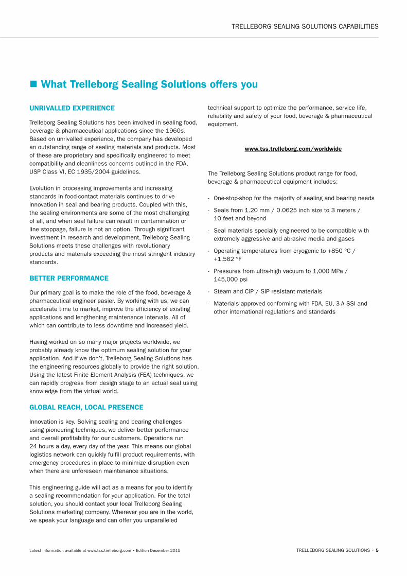
UnRIVALLED ExPERIEnCE
Trelleborg Sealing Solutions has been involved in sealing food, beverage & pharmaceutical applications since the 1960s. Based on unrivalled experience, the company has developed an outstanding range of sealing materials and products. Most of these are proprietary and specifically engineered to meet compatibility and cleanliness concerns outlined in the FDA, USP Class VI, EC 1935/2004 guidelines.
Evolution in processing improvements and increasing standards in food-contact materials continues to drive innovation in seal and bearing products. Coupled with this, the sealing environments are some of the most challenging of all, and when seal failure can result in contamination or line stoppage, failure is not an option. Through significant investment in research and development, Trelleborg Sealing Solutions meets these challenges with revolutionary products and materials exceeding the most stringent industry standards.
BETTER PERFORMAnCE
Our primary goal is to make the role of the food, beverage & pharmaceutical engineer easier. By working with us, we can accelerate time to market, improve the efficiency of existing applications and lengthening maintenance intervals. All of which can contribute to less downtime and increased yield.
Having worked on so many major projects worldwide, we probably already know the optimum sealing solution for your application. And if we don’t, Trelleborg Sealing Solutions has the engineering resources globally to provide the right solution. Using the latest Finite Element Analysis (FEA) techniques, we can rapidly progress from design stage to an actual seal using knowledge from the virtual world.
GLOBAL REACH, LOCAL PRESEnCE
Innovation is key. Solving sealing and bearing challenges using pioneering techniques, we deliver better performance and overall profitability for our customers. Operations run 24 hours a day, every day of the year. This means our global logistics network can quickly fulfill product requirements, with emergency procedures in place to minimize disruption even when there are unforeseen maintenance situations.
This engineering guide will act as a means for you to identify a sealing recommendation for your application. For the total solution, you should contact your local Trelleborg Sealing Solutions marketing company. Wherever you are in the world, we speak your language and can offer you unparalleled
technical support to optimize the performance, service life, reliability and safety of your food, beverage & pharmaceutical equipment.
www.tss.trelleborg.com/worldwide
The Trelleborg Sealing Solutions product range for food, beverage & pharmaceutical equipment includes:
- One-stop-shop for the majority of sealing and bearing needs
- Seals from 1.20 mm / 0.0625 inch size to 3 meters / 10 feet and beyond
- Seal materials specially engineered to be compatible with extremely aggressive and abrasive media and gases
- Operating temperatures from cryogenic to +850 °C / +1,562 °F
- Pressures from ultra-high vacuum to 1,000 MPa / 145,000 psi
- Steam and CIP / SIP resistant materials
- Materials approved conforming with FDA, EU, 3-A SSI and other international regulations and standards
� What Trelleborg Sealing Solutions offers you
FBP_neues_Layout_2015.indb 5 17.10.2016 13:34:39
STANDARDS AND REGULATIONS
6 • TRELLEBORG SEALING SOLUTIONS Latest information available at www.tss.trelleborg.com • Edition December 2015
� Standards and RegulationsStandards and regulations are vital to ensuring products are safe for human consumption. Trelleborg Sealing Solutions are committed to understanding these from a seals and bearings point of view and make sure that products supplied are compliant. We offer materials that conform with 3-A standards and are a symbol holder for some plastic materials. We also manufacture seals that have been designed according to EHEDG design rules.
European Hygienic Engineering and Design Group (EHEDG)Founded in 1989, the European Hygienic Engineering and Design Group (EHEDG) is a consortium of equipment manufacturers, food processors and their suppliers, research institutes and universities as well as public health authorities, whose common goal is the promotion and improvement of hygiene during the processing and packaging of food products.
EHEDG helps create a central, internationally recognized source of information by imparting knowledge on hygienic engineering of equipment and by specifying best practices in respect to their hygienic operation, supply and maintenance. EHEDG actively supports legislation and offers an advancement of know-how in the hygienic design of process units. Knowledge gaps are identified in order to enhance research in these areas.
Guidelines, certification and trainingTo date, the EHEDG subgroups have developed more than 40 guidelines which describe the most important hygiene-relevant design features and offer their readers guidance and practical advice in implementing national and international legislation into their design practices and manufacturing processes. These documents provide state-of-the-art know-how and are available in many languages.
The EHEDG test and certification institutes are internationally recognized and set quality standards for use in the food industry in accordance to the highest hygienic standards. About 400 components have been EHEDG-certified as of today.
EHEDG training courses are specially developed as a train-the-trainer program for equipment manufacturers or instructors from the food industry who want to gain a deeper understanding of hygienic engineering and applications in the field. EHEDG training offers a balanced and modular system of lectures and practical sessions on a local and international level.
The EHEDG regional sections in Europe and overseas help promote hygienic manufacturing of food through their activities. These groups organize local meetings, seminars, workshops and training courses. All EHEDG congresses and symposia are a gathering of hygienic design expertise and a meeting point of all interested target groups. Skilled EHEDG experts share their know-how and deliver an insight into their work. Furthermore, EHEDG provides articles on selected topics in the international scientific and technical press, are present on internet platforms and deliver comprehensive information on its activities and achievements in its yearbook.
MembershipEHEDG is aiming to enhance the dialogue between equipment manufacturers, food producers, scientists and public health authorities, offering its members an international knowledge platform and guidance in hygienic design and engineering. The EHEDG members include:
- Individuals providing expertise or just interested in learning more about hygienic design
- Companies for the manufacturing of food and food equipment, pharmaceutical and cosmetic production
- Companies supplying engineering services
- Universities, scientific and research organizations
- Health authorities
All individual members, companies and institutes are essential to help EHEDG achieve its long-term goal of assisting in the prevention of food hygiene problems through the application of hygienic engineering. The member companies and organizations are committed to the highest standards of food safety and strive to improve the overall image of the industry in the eyes of the consumer. Through the network within the EHEDG organization and its objectives, they can promote their views related to their scope of expertise and can influence trends and earn international recognition for their efforts.
FBP_neues_Layout_2015.indb 6 17.10.2016 13:34:40
STANDARDS AND REGULATIONS
TRELLEBORG SEALING SOLUTIONS • 7Latest information available at www.tss.trelleborg.com • Edition December 2015
� 3-A Sanitary Standards, Inc. (SSI)The organization once known simply as "3-A" is distinguished by a remarkable history of serving public health through the development of standards for the advancement of food sanitation and hygiene.
The first 3-A Sanitary Standards were developed in the late 1920s through the cooperative efforts of the International Association of Food Industry Suppliers (IAFIS)*, the International Association for Food Protection (IAFP) and the Milk Industry Foundation (MIF).
Over time, the structure of 3-A expanded to encompass a broader group of processors, equipment manufacturers and sanitarians in step with the changing structure of the industry. In 1944, the modern 3-A program was established through the formation of the Dairy Industry Committee, consisting of five national dairy processor groups and one supplier association: The American Butter Institute, American Dairy Products Institute, International Association of Food Industry Suppliers (IAFIS), International Ice Cream Association, Milk Industry Foundation (MIF), and the National Cheese Institute. It was also in 1944 that the U.S. Public Health Service committed to full cooperation with the 3-A program.
The interests of dairy cooperatives were integrated into 3-A in 1996 with the Farm Industry Committee, established by the National Milk Producers Federation.
The Emergence of 3-A Sanitary Standards, Inc.An exciting new era in the history of 3-A began in late 2002 with the incorporation of 3-A Sanitary Standards, Inc. (3-A SSI). The five founding members include the American Dairy Products Institute (ADPI), IAFIS, the International Association for Food Protection (IAFP), the International Dairy Foods Association (IDFA), and the 3-A Sanitary Standards Symbol Administrative Council. Along with the founding members, the leadership of 3-A SSI includes the Food & Drug Administration (FDA), the U.S. Department of Agriculture (USDA), and the 3-A Steering Committee.
The mission and goals of the new non-profit organization reflect many elements of the historic 3-A program, including the development of voluntary standards and accepted practices.
The new 3-A SSI maintains many significant added responsibilities, including oversight of the 3-A Symbol used to identify equipment manufactured to 3-A Sanitary Standards. Under the direction of 3-A SSI, a new program was launched in 2003 to enhance the recognition of the 3-A Symbol with a new Third Party Verification (TPV) program.
*IAFIS is now the Food Processing Suppliers Association.
The 3-A SSI MissionYesterday and today, the mission of 3-A SSI is to enhance product safety for consumers of food, beverages, and pharmaceutical products through the development and use of 3-A Sanitary Standards and 3-A Accepted Practices.
3-A SSI ObjectivesThe leadership of 3-A SSI established comprehensive objectives to enhance the positive role and the visibility of 3-A SSI. These objectives include:
- Develop, maintain and publish uniform standards and practices for sanitary (hygienic) design, fabrication, installation and operation of equipment and machinery.
- Use state-of-the-art, science-based expertise for the development of sanitary standards and accepted practices.
- Harmonize with global standards and guidelines as appropriate.
- Promote the use of 3-A Sanitary Standards, 3-A Accepted Practices, and the 3-A Symbol.
- Authorize use and maintain the integrity of the 3-A Symbol.
- Maintain a uniform system to regulate and enforce proper use of the 3-A Symbol to best enhance consumer product safety.
- Provide education concerning sanitary design principles, application of 3-A Sanitary Standards, 3-A Accepted Practices, and use of the 3-A symbol.
FBP_neues_Layout_2015.indb 7 17.10.2016 13:34:40
STANDARDS AND REGULATIONS
8 • TRELLEBORG SEALING SOLUTIONS Latest information available at www.tss.trelleborg.com • Edition December 2015
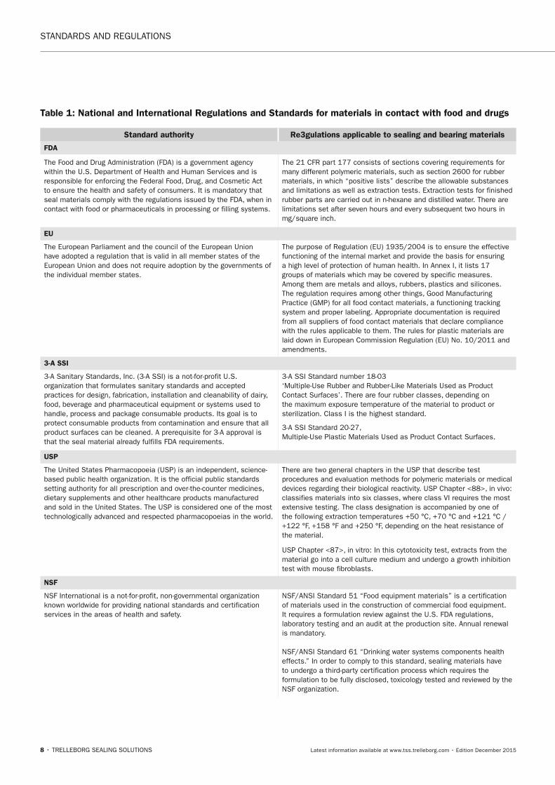
Table 1: national and International Regulations and Standards for materials in contact with food and drugs
Standard authority Re3gulations applicable to sealing and bearing materials
FDA
The Food and Drug Administration (FDA) is a government agency within the U.S. Department of Health and Human Services and is responsible for enforcing the Federal Food, Drug, and Cosmetic Act to ensure the health and safety of consumers. It is mandatory that seal materials comply with the regulations issued by the FDA, when in contact with food or pharmaceuticals in processing or filling systems.
The 21 CFR part 177 consists of sections covering requirements for many different polymeric materials, such as section 2600 for rubber materials, in which “positive lists” describe the allowable substances and limitations as well as extraction tests. Extraction tests for finished rubber parts are carried out in n-hexane and distilled water. There are limitations set after seven hours and every subsequent two hours in mg/square inch.
EU
The European Parliament and the council of the European Union have adopted a regulation that is valid in all member states of the European Union and does not require adoption by the governments of the individual member states.
The purpose of Regulation (EU) 1935/2004 is to ensure the effective functioning of the internal market and provide the basis for ensuring a high level of protection of human health. In Annex I, it lists 17 groups of materials which may be covered by specific measures. Among them are metals and alloys, rubbers, plastics and silicones. The regulation requires among other things, Good Manufacturing Practice (GMP) for all food contact materials, a functioning tracking system and proper labeling. Appropriate documentation is required from all suppliers of food contact materials that declare compliance with the rules applicable to them. The rules for plastic materials are laid down in European Commission Regulation (EU) No. 10/2011 and amendments.
3-A SSI
3-A Sanitary Standards, Inc. (3-A SSI) is a not-for-profit U.S. organization that formulates sanitary standards and accepted practices for design, fabrication, installation and cleanability of dairy, food, beverage and pharmaceutical equipment or systems used to handle, process and package consumable products. Its goal is to protect consumable products from contamination and ensure that all product surfaces can be cleaned. A prerequisite for 3-A approval is that the seal material already fulfills FDA requirements.
3-A SSI Standard number 18-03 ‘Multiple-Use Rubber and Rubber-Like Materials Used as Product Contact Surfaces’. There are four rubber classes, depending on the maximum exposure temperature of the material to product or sterilization. Class I is the highest standard.
3-A SSI Standard 20-27, Multiple-Use Plastic Materials Used as Product Contact Surfaces.
USP
The United States Pharmacopoeia (USP) is an independent, science-based public health organization. It is the official public standards setting authority for all prescription and over-the-counter medicines, dietary supplements and other healthcare products manufactured and sold in the United States. The USP is considered one of the most technologically advanced and respected pharmacopoeias in the world.
There are two general chapters in the USP that describe test procedures and evaluation methods for polymeric materials or medical devices regarding their biological reactivity. USP Chapter <88>, in vivo: classifies materials into six classes, where class VI requires the most extensive testing. The class designation is accompanied by one of the following extraction temperatures +50 °C, +70 °C and +121 °C / +122 °F, +158 °F and +250 °F, depending on the heat resistance of the material.
USP Chapter <87>, in vitro: In this cytotoxicity test, extracts from the material go into a cell culture medium and undergo a growth inhibition test with mouse fibroblasts.
nSF
NSF International is a not-for-profit, non-governmental organization known worldwide for providing national standards and certification services in the areas of health and safety.
NSF/ANSI Standard 51 “Food equipment materials” is a certification of materials used in the construction of commercial food equipment. It requires a formulation review against the U.S. FDA regulations, laboratory testing and an audit at the production site. Annual renewal is mandatory. NSF/ANSI Standard 61 “Drinking water systems components health effects.” In order to comply to this standard, sealing materials have to undergo a third-party certification process which requires the formulation to be fully disclosed, toxicology tested and reviewed by the NSF organization.
FBP_neues_Layout_2015.indb 8 17.10.2016 13:34:40
STANDARDS AND REGULATIONS
TRELLEBORG SEALING SOLUTIONS • 9Latest information available at www.tss.trelleborg.com • Edition December 2015
Standard authority Re3gulations applicable to sealing and bearing materials
BfR
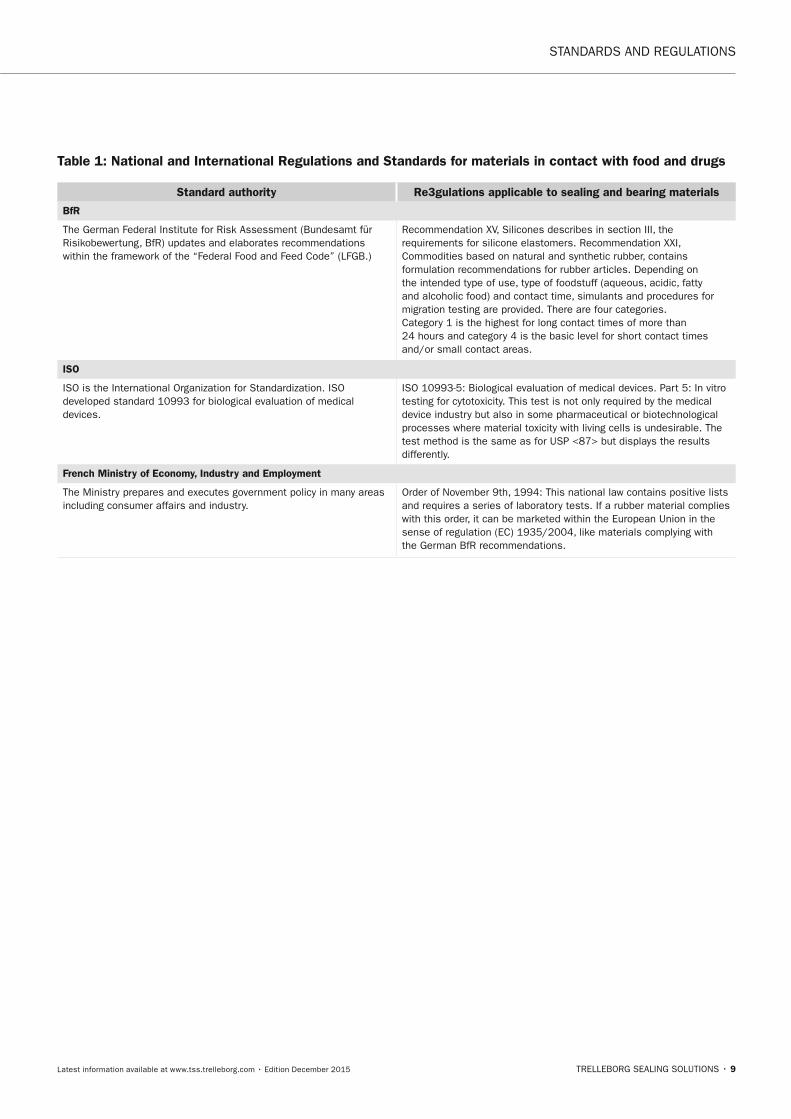
The German Federal Institute for Risk Assessment (Bundesamt für Risikobewertung, BfR) updates and elaborates recommendations within the framework of the “Federal Food and Feed Code” (LFGB.)
Recommendation XV, Silicones describes in section III, the requirements for silicone elastomers. Recommendation XXI, Commodities based on natural and synthetic rubber, contains formulation recommendations for rubber articles. Depending on the intended type of use, type of foodstuff (aqueous, acidic, fatty and alcoholic food) and contact time, simulants and procedures for migration testing are provided. There are four categories. Category 1 is the highest for long contact times of more than 24 hours and category 4 is the basic level for short contact times and/or small contact areas.
ISO
ISO is the International Organization for Standardization. ISO developed standard 10993 for biological evaluation of medical devices.
ISO 10993-5: Biological evaluation of medical devices. Part 5: In vitro testing for cytotoxicity. This test is not only required by the medical device industry but also in some pharmaceutical or biotechnological processes where material toxicity with living cells is undesirable. The test method is the same as for USP <87> but displays the results differently.
French Ministry of Economy, Industry and Employment
The Ministry prepares and executes government policy in many areas including consumer affairs and industry.
Order of November 9th, 1994: This national law contains positive lists and requires a series of laboratory tests. If a rubber material complies with this order, it can be marketed within the European Union in the sense of regulation (EC) 1935/2004, like materials complying with the German BfR recommendations.
Table 1: national and International Regulations and Standards for materials in contact with food and drugs
FBP_neues_Layout_2015.indb 9 17.10.2016 13:34:40

10 • TRELLEBORG SEALING SOLUTIONS Latest information available at www.tss.trelleborg.com • Edition December 2015
FBP_neues_Layout_2015.indb 10 17.10.2016 13:34:40
TRELLEBORG SEALING SOLUTIONS • 11Latest information available at www.tss.trelleborg.com • Edition December 2015
Hardware & Design Expertise
Hardware &Design ExpertiseHardware &Design ExpertiseHardware &
FBP_neues_Layout_2015.indb 11 17.10.2016 13:34:42

12 • TRELLEBORG SEALING SOLUTIONS Latest information available at www.tss.trelleborg.com • Edition December 2015
HARDWARE & DESIGN EXPERTISE · Surface Finishes
FBP_neues_Layout_2015.indb 12 17.10.2016 13:34:42
TRELLEBORG SEALING SOLUTIONS • 13Latest information available at www.tss.trelleborg.com • Edition December 2015
HARDWARE & DESIGN EXPERTISE · Surface Finishes
HARDWARE & DESIGn ExPERTISEThe functioning of seals not only depends on the seal itself and its operating conditions, but also on other factors. Over the years Trelleborg Sealing Solutions has developed an in-depth knowledge of applied materials technology. To maximize system performance, we can advise on relevant issues related to the hardware into which seals are fitted and significant properties of mating surfaces.
In this section, we provide recommendations on surface finishes and hardness requirements, as well as offering advice on mating surfaces such as preferred coatings and platings. To find out more, contact your local Trelleborg Sealing Solutions marketing company. It is best to involve them at concept stage. This allows them to advise on the design of the component or housing to ensure that it will function as effectively as possible and give maximum seal life and performance.
� Surface FinishesSurface finish quality relates directly to dynamic seal performance and cleanability of the equipment. Properly defining, measuring and controlling surface finish quality is critical to the functional reliability and service life of a seal.
Developments in surface finish measurement equipment and capabilities, along with finishing methods, have resulted in functional seal testing being performed to determine and verify surface finish recommendations for improved seal performance.
STAnDARD RECOMMEnDATIOnSTwo sets of standard recommendations that apply to linear hydraulic seals and dynamic sealing surfaces are given below. The first is for HVOF (High Velocity Oxygen Fuel) applied coatings like Tungsten Carbide and Cobalt-Chrome (Wc-Co-Cr). The second is for bare steel, aluminum or chrome plating. Within the product sections you will find further product specific surface finish recommendations.
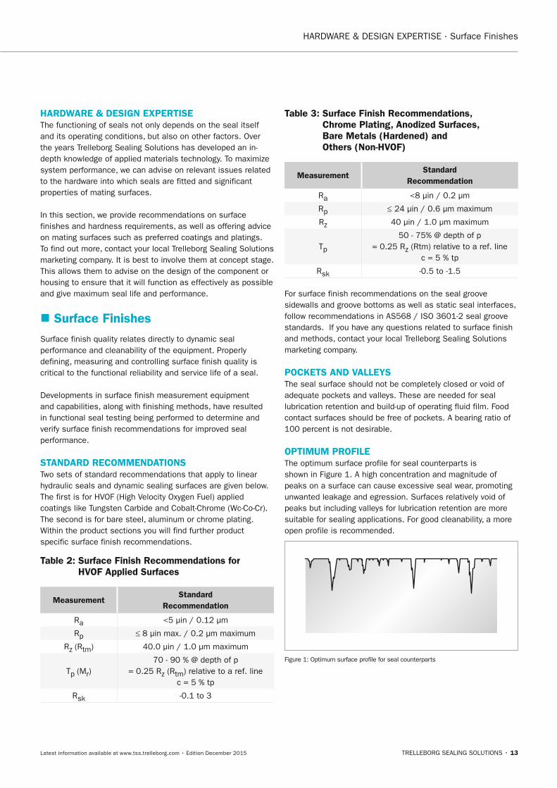
Table 2: Surface Finish Recommendations for HVOF Applied Surfaces
MeasurementStandard
Recommendation
Ra <5 µin / 0.12 µm
Rp ≤ 8 µin max. / 0.2 µm maximum
Rz (Rtm) 40.0 µin / 1.0 µm maximum
Tp (Mr)70 - 90 % @ depth of p
= 0.25 Rz (Rtm) relative to a ref. line c = 5 % tp
Rsk -0.1 to 3
Table 3: Surface Finish Recommendations, Chrome Plating, Anodized Surfaces, Bare Metals (Hardened) and Others (non-HVOF)
MeasurementStandard
Recommendation
Ra <8 µin / 0.2 µm
Rp ≤ 24 µin / 0.6 µm maximum
Rz 40 µin / 1.0 µm maximum
Tp
50 - 75% @ depth of p= 0.25 Rz (Rtm) relative to a ref. line
c = 5 % tp
Rsk -0.5 to -1.5
For surface finish recommendations on the seal groove sidewalls and groove bottoms as well as static seal interfaces, follow recommendations in AS568 / ISO 3601-2 seal groove standards. If you have any questions related to surface finish and methods, contact your local Trelleborg Sealing Solutions marketing company.
POCKETS AnD VALLEySThe seal surface should not be completely closed or void of adequate pockets and valleys. These are needed for seal lubrication retention and build-up of operating fluid film. Food contact surfaces should be free of pockets. A bearing ratio of 100 percent is not desirable.
OPTIMUM PROFILEThe optimum surface profile for seal counterparts is shown in Figure 1. A high concentration and magnitude of peaks on a surface can cause excessive seal wear, promoting unwanted leakage and egression. Surfaces relatively void of peaks but including valleys for lubrication retention are more suitable for sealing applications. For good cleanability, a more open profile is recommended.
Figure 1: Optimum surface profile for seal counterparts
FBP_neues_Layout_2015.indb 13 17.10.2016 13:34:43
14 • TRELLEBORG SEALING SOLUTIONS Latest information available at www.tss.trelleborg.com • Edition December 2015
HARDWARE & DESIGN EXPERTISE · Surface Finishes
DIRECTIOn OF LAy Each method used to obtain a specific surface finish, such as turning, grinding, honing, ball peening, polishing or superfinishing, produces a characteristic direction or lay to the surface. This can have an effect on sealing performance and wear patterns in certain applications.
To obtain the best seal performance, avoid finishing methods which promote the formation of leak paths in your application. For example, avoid a strong axial lay in a reciprocating rod seal application or a definite spiral pattern on the shaft in a rotary application.
MATInG SURFACE HARDnESS The hardness of the surface that mates with the seal affects the seal’s performance in several ways.
If mating materials are too soft, the seal will burnish or damage the surface. A harder material improves wear life, resisting damage by the seal. Hard surfaces also have a tendency to lower the running friction of a seal.
A seal will polish its mating surface, especially if it is a softer metal. For example, a reciprocating rod made of stainless steel with a hardness of 28 to 30 Rockwell C and a finish of 25 µin/ 0.635 µm Ra will generally be polished by the seal to a finish of 12 µin / 0.305 µm Ra or better, over a short period of time. Seal friction and wear will then decrease accordingly. Materials that are harder than 44 Rockwell C do not polish as easily.
Turcon® seal materials with reinforcing fillers, such as MF4 and MF6, should only be specified against harder mating surfaces. In some cases, reinforcing fillers can burnish or damage softer mating surfaces, especially in rotary applications.
When an application requires the longest possible wear life under moderate to severe conditions, the seal material should be one of the harder, highly-filled Turcon® blends.
RUn-In PHASEIn standard sealing systems, the seals and mating surfaces have an initial period of high wear. This phase, known as the run-in, ends once the peaks on the mating surface are broken off and the surface and seal reach an equilibrium state. Provided the seals are sufficiently lubricated, the wear rate drops significantly once the equilibrium state is reached.
By defining the surface finish using multiple surface finish parameters, the overall surface profile can be controlled more precisely. This reduces the sealing system run-in period, and once equilibrium between the seal and sealing surface is reached, gives a more optimal surface finish for leakage control, wear resistance and service life.
The abrasive nature of a rough finish can cause excessive seal wear during the early run-in period. Therefore, the harder the mating surface, the more important it is to start with the correct surface finish.
SUBSTRATES, PLATInGS AnD COATInGSIn most applications an unplated, uncoated shaft is more than adequate. Typical mating surface materials are listed in Tables 4 and 5. These materials (and others not listed) can also act as substrates for platings or coatings to achieve higher hardness values. An important property to consider in such cases is the ability of the substrate to support the plating. For example, when a high pressure load is exerted on a Variseal®
running against a hard chrome plating on a soft substrate (such as 300 series stainless steel) the plating may peel or crack and then abrade the seal. A better substrate would be stainless steel Type 440C (hardened to 44 Rockwell C) or an alloy steel such as 4340 in the fully hardened condition.
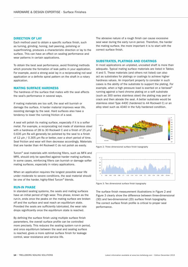
Figure 2: Three dimensional surface finish topography
Figure 3: Two dimensional surface finish topography
The surface finish measurement illustrations in Figure 2 and Figure 3 clearly show the difference between three-dimensional (3D) and two-dimensional (2D) surface finish topography. The correct surface finish profile is critical to proper seal performance.
FBP_neues_Layout_2015.indb 14 17.10.2016 13:34:44
TRELLEBORG SEALING SOLUTIONS • 15Latest information available at www.tss.trelleborg.com • Edition December 2015
HARDWARE & DESIGN EXPERTISE · Shaft Materials
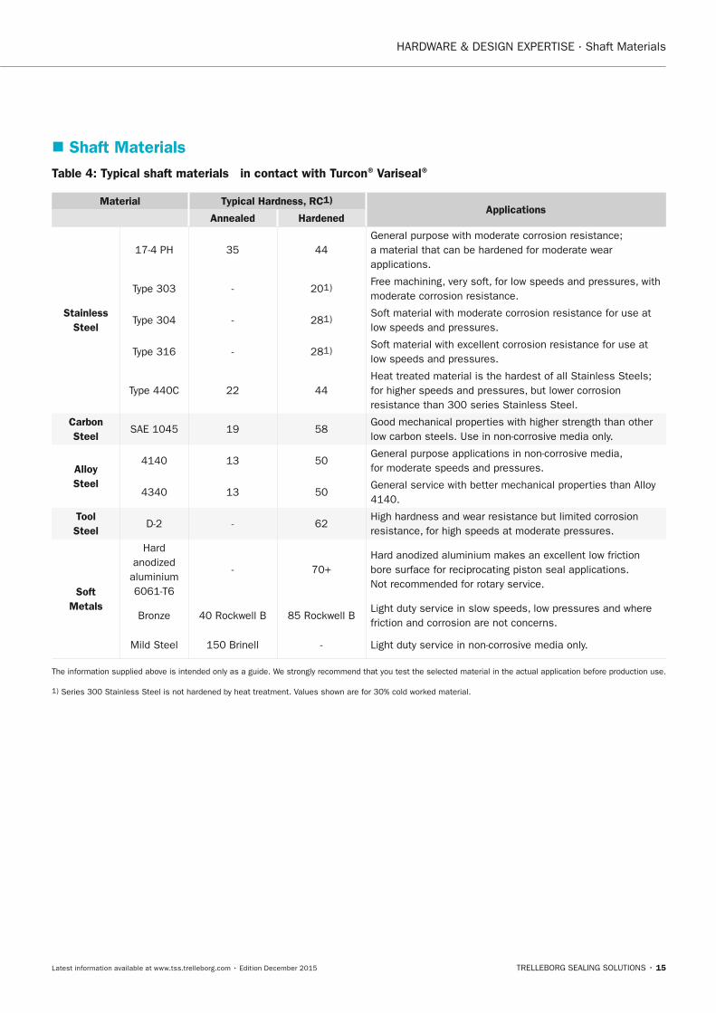
� Shaft MaterialsTable 4: Typical shaft materials in contact with Turcon® Variseal®
Material Typical Hardness, RC1) Applications
Annealed Hardened
Stainless Steel
17-4 PH 35 44General purpose with moderate corrosion resistance; a material that can be hardened for moderate wear applications.
Type 303 - 201) Free machining, very soft, for low speeds and pressures, with moderate corrosion resistance.
Type 304 - 281) Soft material with moderate corrosion resistance for use at low speeds and pressures.
Type 316 - 281) Soft material with excellent corrosion resistance for use at low speeds and pressures.
Type 440C 22 44Heat treated material is the hardest of all Stainless Steels; for higher speeds and pressures, but lower corrosion resistance than 300 series Stainless Steel.
Carbon Steel
SAE 1045 19 58Good mechanical properties with higher strength than other low carbon steels. Use in non-corrosive media only.
Alloy Steel
4140 13 50General purpose applications in non-corrosive media, for moderate speeds and pressures.
4340 13 50General service with better mechanical properties than Alloy 4140.
Tool Steel
D-2 - 62High hardness and wear resistance but limited corrosion resistance, for high speeds at moderate pressures.
Soft Metals
Hard anodized
aluminium 6061-T6
- 70+Hard anodized aluminium makes an excellent low friction bore surface for reciprocating piston seal applications. Not recommended for rotary service.
Bronze 40 Rockwell B 85 Rockwell BLight duty service in slow speeds, low pressures and where friction and corrosion are not concerns.
Mild Steel 150 Brinell - Light duty service in non-corrosive media only.
The information supplied above is intended only as a guide. We strongly recommend that you test the selected material in the actual application before production use.
1) Series 300 Stainless Steel is not hardened by heat treatment. Values shown are for 30% cold worked material.
FBP_neues_Layout_2015.indb 15 17.10.2016 13:34:44
16 • TRELLEBORG SEALING SOLUTIONS Latest information available at www.tss.trelleborg.com • Edition December 2015
HARDWARE & DESIGN EXPERTISE · Plating and Coating
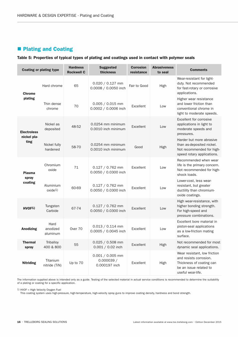
� Plating and CoatingTable 5: Properties of typical types of plating and coatings used in contact with polymer seals
Coating or plating typeHardness
Rockwell CSuggested thickness
Corrosion resistance
Abrasiveness to seal
Comments
Chrome plating
Hard chrome 650.020 / 0.127 mm
0.0008 / 0.0050 inchFair to Good High
Wear-resistant for light-duty. Not recommended for fast-rotary or corrosive applications.
Thin dense chrome
700.005 / 0.015 mm
0.0002 / 0.0006 inchExcellent Low
Higher wear resistance and lower friction than conventional chrome in light to moderate speeds.
Electroless nickel pla-
ting
Nickel as deposited
48-520.0254 mm minimum0.0010 inch minimum
Excellent Low
Excellent for corrosive applications in light to moderate speeds and pressures.
Nickel fully hardened
58-700.0254 mm minimum0.0010 inch minimum
Good High
Harder but more abrasive than as-deposited nickel. Not recommended for high-speed rotary applications.
Plasma spray
coating
Chromium oxide
71 0.127 / 0.762 mm 0.0050 / 0.0300 inch
Excellent Low
Recommended when wear life is the primary concern. Not recommended for high-shock loads.
Aluminium oxide1) 60-69
0.127 / 0.762 mm0.0050 / 0.0300 inch
Excellent Low
Lower-cost, less wear-resistant, but greater ductility than chromium-oxide coatings.
HVOF1) Tungsten Carbide
67-740.127 / 0.762 mm
0.0050 / 0.0300 inchExcellent Low
High wear-resistance, with higher bonding strength. For high-speed and pressure combinations.
AnodizingHard
anodized aluminum
Over 700.013 / 0.114 mm
0.0005 / 0.0045 inchExcellent Low
Excellent bore material in piston-seal applications as a low-friction mating surface.
Thermalspray
Triballoy400 & 800
550.025 / 0.508 mm0.001 / 0.02 inch
Excellent HighNot recommended for most dynamic seal applications.
nitridingTitanium
nitride (TiN)Up to 70
0.001 / 0.005 mm0.000039 /
0.000197 inchExcellent High
Wear resistant, low friction and resists corrosion. Thickness of coating can be an issue related to useful wear-life.
The information supplied above is intended only as a guide. Testing of the selected material in actual service conditions is recommended to determine the suitability of a plating or coating for a specific application.
1) HVOF = High Velocity Oxygen Fuel This coating system uses high-pressure, high-temperature, high-velocity spray guns to improve coating density, hardness and bond strength.
FBP_neues_Layout_2015.indb 16 17.10.2016 13:34:45
TRELLEBORG SEALING SOLUTIONS • 17Latest information available at www.tss.trelleborg.com • Edition December 2015
HARDWARE & DESIGN EXPERTISE · Flexcoat FF Coating
� Flexcoat™ FF Coating – FDA assembly aid
Flexcoat™ FF is a coating for seals that has been specifically developed for hygienic processing environments and will ease automated or manual seal assembly processes.
As required for food and beverage processing, it is in compliance with the FDA Regulation 21 CFR Chapter I Part 178.3570.
In addition, it is approved according to the German Lebensmittel- und Bedarfsgegenständegesetzes LMBG (Foodstuffs and Commodities Act) §5 para. 1 and §31 para. 1 and complies with the requirements of the German
Umweltbundesamt UBA (German Federal Environmental Agency, FEA) on organic coatings for seals in potable water applications for cold and hot water (+85 °C / +185 °F).
Finally, it complies with the requirements of the German DVGW technical standard W 270 for the use in potable water.
For further information on this or other coating solutions, refer to the Trelleborg Sealing Solutions Flexcoat™ – Friction-free Running brochure.
FBP_neues_Layout_2015.indb 17 17.10.2016 13:34:49
HARDWARE & DESIGN EXPERTISE · Hardware Design Tips
18 • TRELLEBORG SEALING SOLUTIONS Latest information available at www.tss.trelleborg.com • Edition December 2015
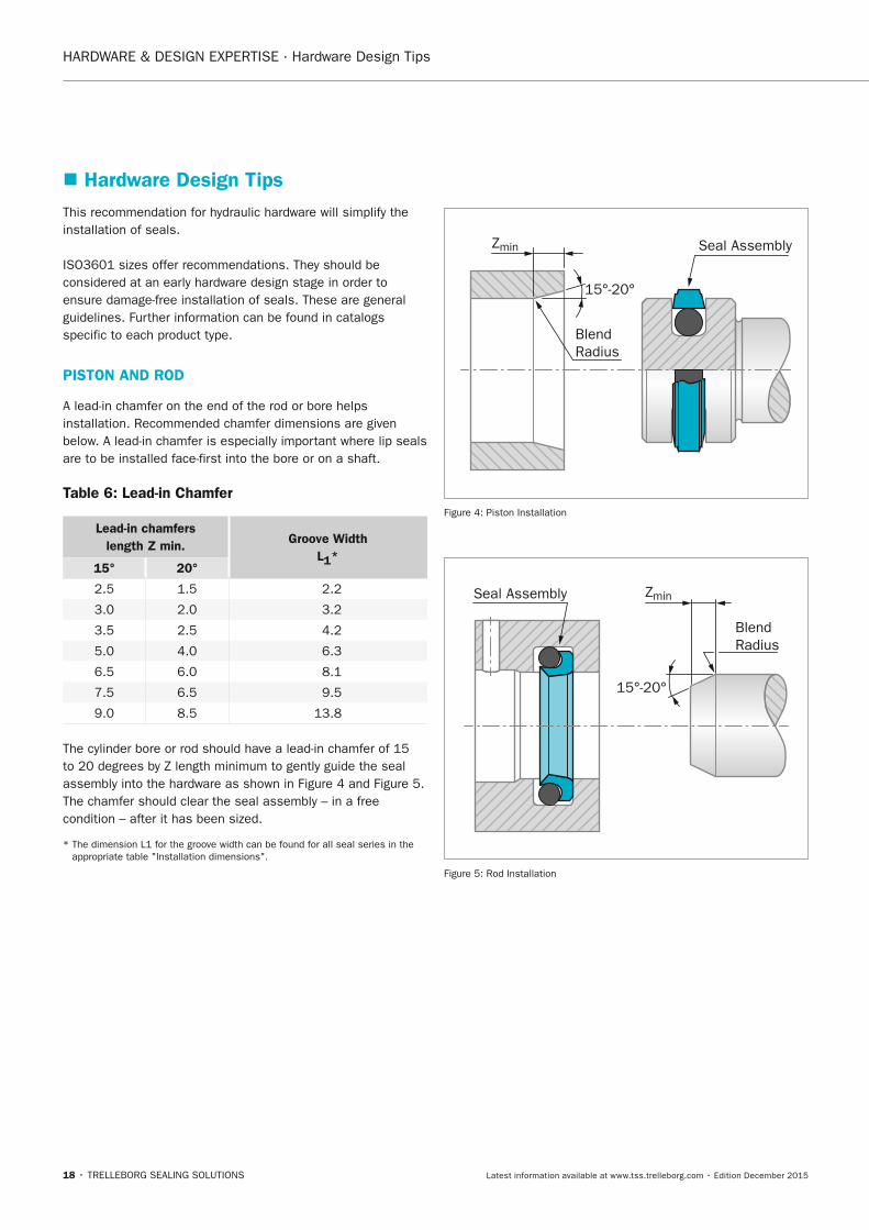
� Hardware Design TipsThis recommendation for hydraulic hardware will simplify the installation of seals.
ISO3601 sizes offer recommendations. They should be considered at an early hardware design stage in order to ensure damage-free installation of seals. These are general guidelines. Further information can be found in catalogs specific to each product type.
PISTOn AnD ROD
A lead-in chamfer on the end of the rod or bore helps installation. Recommended chamfer dimensions are given below. A lead-in chamfer is especially important where lip seals are to be installed face-first into the bore or on a shaft.
Table 6: Lead-in Chamfer
Lead-in chamfers length Z min. Groove Width
L1*15° 20°
2.5 1.5 2.2
3.0 2.0 3.2
3.5 2.5 4.2
5.0 4.0 6.3
6.5 6.0 8.1
7.5 6.5 9.5
9.0 8.5 13.8
The cylinder bore or rod should have a lead-in chamfer of 15 to 20 degrees by Z length minimum to gently guide the seal assembly into the hardware as shown in Figure 4 and Figure 5. The chamfer should clear the seal assembly – in a free condition – after it has been sized.
* The dimension L1 for the groove width can be found for all seal series in the appropriate table "Installation dimensions".
BlendRadius
Seal Assembly
15°-20°
Zmin
Figure 4: Piston Installation
BlendRadius
Seal Assembly
15°-20°
Zmin
Figure 5: Rod Installation
FBP_neues_Layout_2015.indb 18 17.10.2016 13:34:50
HARDWARE & DESIGN EXPERTISE · Hardware Design Tips
TRELLEBORG SEALING SOLUTIONS • 19Latest information available at www.tss.trelleborg.com • Edition December 2015
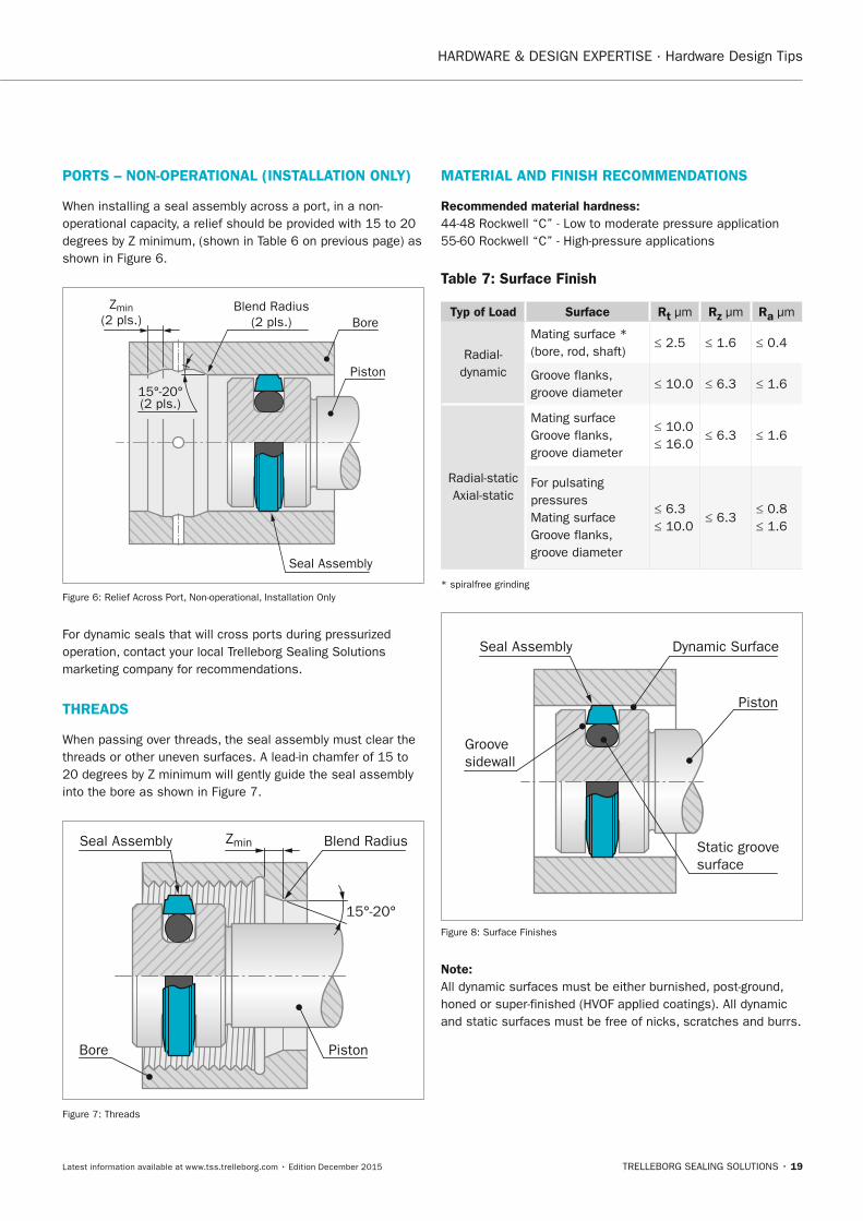
PORTS – nOn-OPERATIOnAL (InSTALLATIOn OnLy)
When installing a seal assembly across a port, in a non-operational capacity, a relief should be provided with 15 to 20 degrees by Z minimum, (shown in Table 6 on previous page) as shown in Figure 6.
Blend Radius(2 pls.)
Zmin(2 pls.)
Piston
Bore
Seal Assembly
15°-20°(2 pls.)
Figure 6: Relief Across Port, Non-operational, Installation Only
For dynamic seals that will cross ports during pressurized operation, contact your local Trelleborg Sealing Solutions marketing company for recommendations.
THREADS
When passing over threads, the seal assembly must clear the threads or other uneven surfaces. A lead-in chamfer of 15 to 20 degrees by Z minimum will gently guide the seal assembly into the bore as shown in Figure 7.
Blend RadiusSeal Assembly
PistonBore
15°-20°
Zmin
Figure 7: Threads
MATERIAL AnD FInISH RECOMMEnDATIOnS
Recommended material hardness:44-48 Rockwell “C” - Low to moderate pressure application 55-60 Rockwell “C” - High-pressure applications
Table 7: Surface Finish
Typ of Load Surface Rt µm Rz µm Ra µm
Radial- dynamic
Mating surface * (bore, rod, shaft)
≤ 2.5 ≤ 1.6 ≤ 0.4
Groove flanks, groove diameter
≤ 10.0 ≤ 6.3 ≤ 1.6
Radial-static Axial-static
Mating surfaceGroove flanks, groove diameter
≤ 10.0 ≤ 16.0
≤ 6.3 ≤ 1.6
For pulsating pressuresMating surfaceGroove flanks, groove diameter
≤ 6.3 ≤ 10.0
≤ 6.3≤ 0.8 ≤ 1.6
* spiralfree grinding
Piston
Seal Assembly Dynamic Surface
Groovesidewall
Static groovesurface
Figure 8: Surface Finishes
note:All dynamic surfaces must be either burnished, post-ground, honed or super-finished (HVOF applied coatings). All dynamic and static surfaces must be free of nicks, scratches and burrs.
FBP_neues_Layout_2015.indb 19 17.10.2016 13:34:51
HARDWARE & DESIGN EXPERTISE · Hardware Design Tips
20 • TRELLEBORG SEALING SOLUTIONS Latest information available at www.tss.trelleborg.com • Edition December 2015
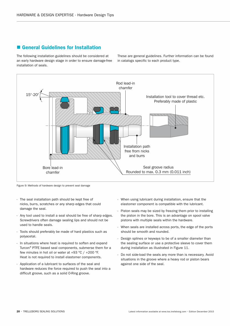
� General Guidelines for InstallationThe following installation guidelines should be considered at an early hardware design stage in order to ensure damage-free installation of seals.
These are general guidelines. Further information can be found in catalogs specific to each product type.
Bore lead-inchamfer
Rod lead-inchamfer
Installation pathfree from nicks
and burrs
Installation tool to cover thread etc.Preferably made of plastic
15°-20°
Seal groove radiusRounded to max. 0.3 mm (0.011 inch)
Figure 9: Methods of hardware design to prevent seal damage
- The seal installation path should be kept free of nicks, burrs, scratches or any sharp edges that could damage the seal.
- Any tool used to install a seal should be free of sharp edges. Screwdrivers often damage sealing lips and should not be used to handle seals.
- Tools should preferably be made of hard plastics such as polyacetal.
- In situations where heat is required to soften and expand Turcon® PTFE based seal components, submerse them for a few minutes in hot oil or water at +93 °C / +200 °F. Heat is not required to install elastomer components.
- Application of a lubricant to surfaces of the seal and hardware reduces the force required to push the seal into a difficult groove, such as a solid O-Ring groove.
- When using lubricant during installation, ensure that the elastomer component is compatible with the lubricant.
- Piston seals may be sized by freezing them prior to installing the piston in the bore. This is an advantage on spool valve pistons with multiple seals within the hardware.
- When seals are installed across ports, the edge of the ports should be smooth and rounded.
- Design splines or keyways to be of a smaller diameter than the sealing surface or use a protective sleeve to cover them during installation as illustrated in Figure 11.
- Do not side-load the seals any more than is necessary. Avoid situations in the groove where a heavy rod or piston bears against one side of the seal.
FBP_neues_Layout_2015.indb 20 17.10.2016 13:34:51
HARDWARE & DESIGN EXPERTISE · Hardware Design Tips
TRELLEBORG SEALING SOLUTIONS • 21Latest information available at www.tss.trelleborg.com • Edition December 2015
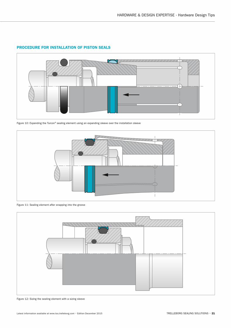
PROCEDURE FOR InSTALLATIOn OF PISTOn SEALS
Figure 10: Expanding the Turcon® sealing element using an expanding sleeve over the installation sleeve
Figure 11: Sealing element after snapping into the groove
Figure 12: Sizing the sealing element with a sizing sleeve
FBP_neues_Layout_2015.indb 21 17.10.2016 13:34:52
HARDWARE & DESIGN EXPERTISE · Hardware Design Tips
22 • TRELLEBORG SEALING SOLUTIONS Latest information available at www.tss.trelleborg.com • Edition December 2015
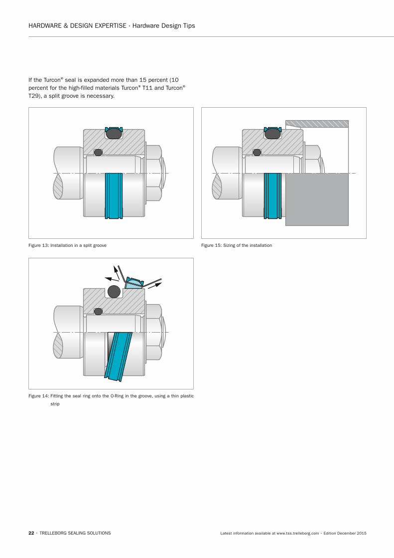
If the Turcon® seal is expanded more than 15 percent (10 percent for the high-filled materials Turcon® T11 and Turcon®
T29), a split groove is necessary.
Figure 13: Installation in a split groove
Figure 14: Fitting the seal ring onto the O-Ring in the groove, using a thin plastic
strip
Figure 15: Sizing of the installation
FBP_neues_Layout_2015.indb 22 17.10.2016 13:34:53
HARDWARE & DESIGN EXPERTISE · Hardware Design Tips
TRELLEBORG SEALING SOLUTIONS • 23Latest information available at www.tss.trelleborg.com • Edition December 2015
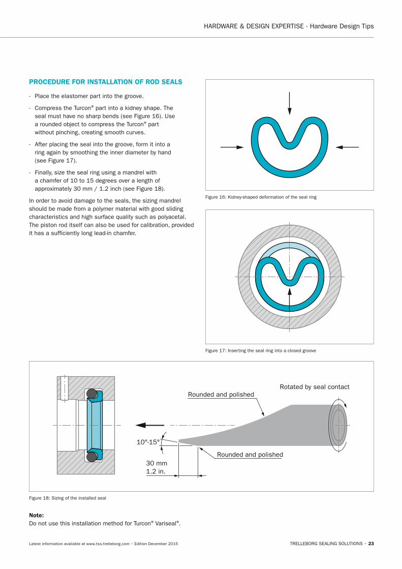
PROCEDURE FOR InSTALLATIOn OF ROD SEALS
- Place the elastomer part into the groove.
- Compress the Turcon® part into a kidney shape. The seal must have no sharp bends (see Figure 16). Use a rounded object to compress the Turcon® part without pinching, creating smooth curves.
- After placing the seal into the groove, form it into a ring again by smoothing the inner diameter by hand (see Figure 17).
- Finally, size the seal ring using a mandrel with a chamfer of 10 to 15 degrees over a length of approximately 30 mm / 1.2 inch (see Figure 18).
In order to avoid damage to the seals, the sizing mandrel should be made from a polymer material with good sliding characteristics and high surface quality such as polyacetal.The piston rod itself can also be used for calibration, provided it has a sufficiently long lead-in chamfer.
Figure 16: Kidney-shaped deformation of the seal ring
Figure 17: Inserting the seal ring into a closed groove
Rotated by seal contactRounded and polished
Rounded and polished30 mm1.2 in.
10°-15°
Figure 18: Sizing of the installed seal
note:Do not use this installation method for Turcon® Variseal®.
FBP_neues_Layout_2015.indb 23 17.10.2016 13:34:54
HARDWARE & DESIGN EXPERTISE · Validation of Products
24 • TRELLEBORG SEALING SOLUTIONS Latest information available at www.tss.trelleborg.com • Edition December 2015
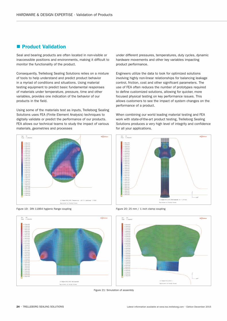
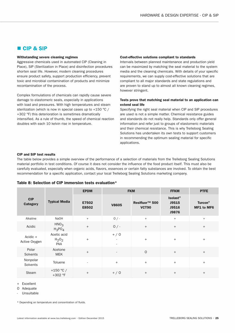
� Product ValidationSeal and bearing products are often located in non-visible or inaccessible positions and environments, making it difficult to monitor the functionality of the product.
Consequently, Trelleborg Sealing Solutions relies on a mixture of tools to help understand and predict product behavior in a myriad of conditions and situations. Using material testing equipment to predict basic fundamental responses of materials under temperature, pressure, time and other variables, provides one indication of the behavior of our products in the field.
Using some of the materials test as inputs, Trelleborg Sealing Solutions uses FEA (Finite Element Analysis) techniques to digitally validate or predict the performance of our products. FEA allows our technical teams to study the impact of various materials, geometries and processes
under different pressures, temperatures, duty cycles, dynamic hardware movements and other key variables impacting product performance.
Engineers utilize the data to look for optimized solutions involving highly non-linear relationships for balancing leakage control, friction, cost and other significant parameters. The use of FEA often reduces the number of prototypes required to define customized solutions, allowing for quicker, more focused physical testing on key performance issues. This allows customers to see the impact of system changes on the performance of a product.
When combining our world leading material testing and FEA work with state-of-the-art product testing, Trelleborg Sealing Solutions produces a very high level of integrity and confidence for all your applications.
Figure 19: DIN 11864 hygienic flange coupling Figure 20: 25 mm / 1 inch clamp coupling
Figure 21: Simulation of assembly
FBP_neues_Layout_2015.indb 24 17.10.2016 13:34:56
HARDWARE & DESIGN EXPERTISE · CIP & SIP
TRELLEBORG SEALING SOLUTIONS • 25Latest information available at www.tss.trelleborg.com • Edition December 2015
� CIP & SIP Withstanding severe cleaning regimesAggressive chemicals used in automated CIP (Cleaning in Place), SIP (Sterilization in Place) and disinfection procedures shorten seal life. However, modern cleaning procedures ensure product safety, support production efficiency, prevent toxic and microbial contamination of products and minimize recontamination of the process.
Complex formulations of chemicals can rapidly cause severe damage to elastomeric seals, especially in applications with load and pressures. With high temperatures and steam sterilization (which is now in special cases up to +150 °C / +302 °F) this deterioration is sometimes dramatically intensified. As a rule of thumb, the speed of chemical reaction doubles with each 10 kelvin rise in temperature.
Cost-effective solutions compliant to standardsIntervals between planned maintenance and production yield can be maximized by matching the seal material to the system media and the cleaning chemicals. With details of your specific requirements, we can supply cost-effective solutions that are compliant to all major standards and state regulations and are proven to stand up to almost all known cleaning regimes, however stringent.
Tests prove that matching seal material to an application can extend seal lifeSpecifying the right seal material when CIP and SIP procedures are used is not a simple matter. Chemical resistance guides and standards do not really help. Standards only offer general information and refer just to groups of elastomeric materials and their chemical resistance. This is why Trelleborg Sealing Solutions has undertaken its own tests to support customers in recommending the optimum sealing material for specific applications.
CIP and SIP test resultsThe table below provides a simple overview of the performance of a selection of materials from the Trelleborg Sealing Solutions material portfolio in test conditions. Of course it does not consider the influence of the food product itself. This must also be carefully evaluated, especially when organic acids, flavors, essences or certain fatty substances are involved. To obtain the best recommendation for a specific application, contact your local Trelleborg Sealing Solutions marketing company.
Table 8: Selection of CIP immersion tests evaluation*
CIP Category
Typical Media
EPDM FKM FFKM PTFE
E7502 E8502
V8605Resifluor™ 500
VCT90
Isolast® J9515 J9516 J9876
Turcon® MF1 to MF6
Alkaline NaOH + O / - + + +
AcidicHNO3 H3PO4
+ O / - + + +
Acidic + Active Oxygen
Acetic acid H2O2 PAA
++ / O
- -
+ + +
Polar Solvents
Acetone MEK
+ - O + +
Nonpolar Solvents
Toluene - + + + +
Steam+150 °C / +302 °F
+ + / O + + +
+ Excellent O Adequate - Unsuitable
* Depending on temperature and concentration of fluids.
FBP_neues_Layout_2015.indb 25 17.10.2016 13:34:56
26 • TRELLEBORG SEALING SOLUTIONS Latest information available at www.tss.trelleborg.com • Edition December 2015
HARDWARE & DESIGN EXPERTISE · CIP Research
� CIP (Cleaning In Place) ResearchCommercially available CIP cleaning media come from within the following broad categories:
- Alkalines without surfactants
- Alkalines with surfactants
- Alkalines with chlorine
- Acidic – organic/inorganic
- Acidic disinfectants (highly oxidative)
- Additives
Important factors in determining seal materialStudies undertaken by Trelleborg Sealing Solutions have evaluated the performance of materials in a wide range of commercially available and commonly used CIP fluids and solvents. As the CIP process is frequently followed by sterilization in saturated steam at, for example, +140 °C / +284 °F, further testing was also carried out in these conditions.
The most relevant physical properties of elastomers have been determined after the exposure to the CIP fluids, such as:
- Volume change
- Weight change
- Change of elongation at break
- Change of tensile strength
- Hardness change
As expected, the intensive CIP fluids and high temperatures brought some elastomers to their performance limits. Importantly though, results from different materials, even within the same family of basic polymers, were vastly different. This has allowed Trelleborg Sealing Solutions to engineer materials that give maximized performance in CIP and SIP regimes.
Making sure the following factors are considered is important to ensure maximum sealing integrity and prevent premature seal failure during the CIP process:
- Exposure time to cleaning and rinsing solutions
- Temperature of CIP fluids
- Concentration of CIP chemicals
- Hygienic design of the equipment or system
- Material behavior, e.g. thermal expansion
Overall conclusionsEPDM materials E7502 and E8502 displayed excellent results in most CIP fluids and steam. Tests proved that these grades can be used with strong polar solvents such as Acetone and Methyl-Ethyl-Ketone (MEK). Due to the non-polar nature of EPDM rubbers, this material group is not recommended for fatty foods and only to some special food grade lubricants, whereas liquid milk products are compatible in many cases.
FKM V8605 reacts quite differently. It shows good performance in inorganic acids and non-polar solvents, however, its exposure time to steam should be limited. Resifluor™ 500 has a unique polymer architecture, meaning it can be used with both polar and non-polar fluids, most CIP media and saturated steam. It also displayed excellent
properties in solvents such as MEK, Toluene and Acetone. In some cases, Resifluor™ 500 can offer solutions where using an FFKM would not be economical.
Isolast® FFKM gave the best performance in all test situations. In addition, it has been proven in steam at temperatures up to +240 °C / +464 °F. This means that Isolast® should be selected for the most critical applications where line stops cannot be tolerated.
Turcon® PTFE based sealing materials have almost universal chemical compatibility and are capable of operating at high temperatures and in steam. This makes them ideal for use in CIP and SIP regimes. The Turcon® MF range of materials has been specially developed for aseptic applications, with compliance to most major standards and state regulations.
FBP_neues_Layout_2015.indb 26 17.10.2016 13:34:57
TRELLEBORG SEALING SOLUTIONS • 27Latest information available at www.tss.trelleborg.com • Edition December 2015
HARDWARE & DESIGN EXPERTISE · CIP Research
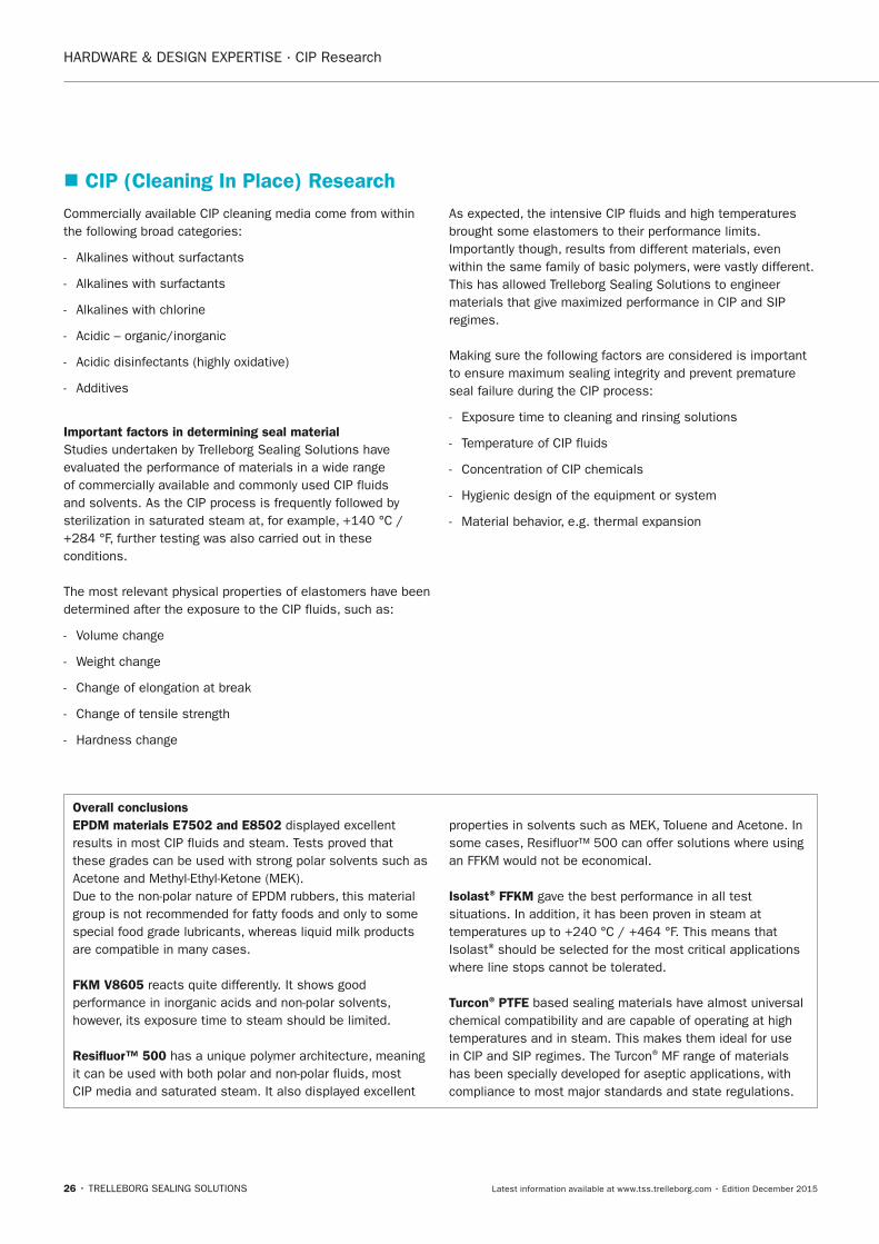
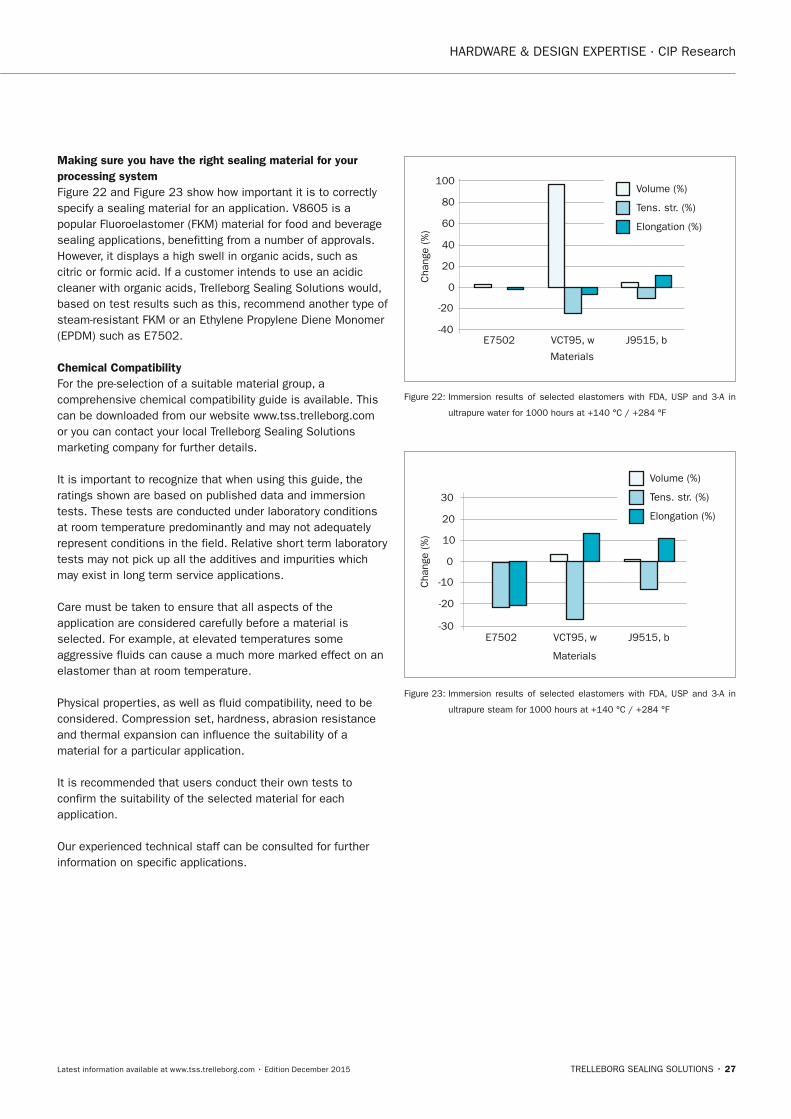
Making sure you have the right sealing material for your processing systemFigure 22 and Figure 23 show how important it is to correctly specify a sealing material for an application. V8605 is a popular Fluoroelastomer (FKM) material for food and beverage sealing applications, benefitting from a number of approvals. However, it displays a high swell in organic acids, such as citric or formic acid. If a customer intends to use an acidic cleaner with organic acids, Trelleborg Sealing Solutions would, based on test results such as this, recommend another type of steam-resistant FKM or an Ethylene Propylene Diene Monomer (EPDM) such as E7502.
Chemical CompatibilityFor the pre-selection of a suitable material group, a comprehensive chemical compatibility guide is available. This can be downloaded from our website www.tss.trelleborg.com or you can contact your local Trelleborg Sealing Solutions marketing company for further details.
It is important to recognize that when using this guide, the ratings shown are based on published data and immersion tests. These tests are conducted under laboratory conditions at room temperature predominantly and may not adequately represent conditions in the field. Relative short term laboratory tests may not pick up all the additives and impurities which may exist in long term service applications.
Care must be taken to ensure that all aspects of the application are considered carefully before a material is selected. For example, at elevated temperatures some aggressive fluids can cause a much more marked effect on an elastomer than at room temperature.
Physical properties, as well as fluid compatibility, need to be considered. Compression set, hardness, abrasion resistance and thermal expansion can influence the suitability of a material for a particular application.
It is recommended that users conduct their own tests to confirm the suitability of the selected material for each application.
Our experienced technical staff can be consulted for further information on specific applications.
Elongation (%)
Tens. str. (%)
Volume (%)
E7502
100
20
60
40
-20
-40
80
J9515, bVCT95, w
Materials
Cha
nge
(%)
0
Figure 22: Immersion results of selected elastomers with FDA, USP and 3-A in
ultrapure water for 1000 hours at +140 °C / +284 °F
Elongation (%)
Tens. str. (%)
Volume (%)
E7502 J9515, bVCT95, w
Materials
Cha
nge
(%) 10
30
20
0
-10
-20
-30
Figure 23: Immersion results of selected elastomers with FDA, USP and 3-A in
ultrapure steam for 1000 hours at +140 °C / +284 °F
FBP_neues_Layout_2015.indb 27 17.10.2016 13:34:57
28 • TRELLEBORG SEALING SOLUTIONS Latest information available at www.tss.trelleborg.com • Edition December 2015
HARDWARE & DESIGN EXPERTISE · Engineered Molded Parts
� Engineered Molded Parts Trelleborg Sealing Solutions offers one of the broadest ranges of sealing elements on the market. Most of the time the tried and tested method works, but sometimes a unique application requires a unique solution. Our specially designed sealing solutions can provide significant benefits from a cost, function, manufacturing or performance perspective, providing you with real competitive advantage.
Working with our engineering teams, Trelleborg Sealing Solutions will support you in the development of a customized engineered molded part designed to suit your individual needs. This may be a flat gasket of any dimension, a rubber-to-metal element or a seal of complex geometry that may consolidate a number of products into one.
Customized sealing components are more than just a product, they are a holistic solution. When developing a customized engineered molded part, Trelleborg Sealing Solutions is not just interested in the function it performs. In addition, we want our seal to perform that function more effectively, at a lower total cost while enhancing your manufacturing process and providing your customer with optimized performance.
Our holistic approach incorporates the following:
Design and valueThe aim of Trelleborg Sealing Solutions is to facilitate customers in achieving cost-effective, durable solutions that match their specific business requirements and needs. Seven research and development centers based around the world, supported with the latest in modeling software and testing apparatus, allow us to modify existing solutions or create entirely new designs to meet the challenges of demanding applications.
MaterialOur capability for quick failure analysis is the key to solving application problems. Trelleborg Sealing Solutions proprietary materials offer outstanding performance on physical, chemical and thermal properties. Our experts and easy-to-use online material search and chemical compatibility check tool allow customers to choose the optimum materials for an application from approximately 2,000 compounds in our global materials database.
Supply chain managementWe are close to our customers through one of our four logistics centers in Europe, the Americas, Japan or China. Exemplary levels of service are recognized and appreciated by customers. These include added value tailored logistics concepts such as special handling, consignment stocking and kitting.
Quality - Robust process landscape with clear accountabilities and
deliverables through our Integrated Management System.
- Customer oriented project management to maximize customer value.
- Comprehensive understanding of applications and customer needs.
- Comprehensive product quality planning and assurance.
- Zero defect culture with world class automated visual inspection capabilities.
- Dedicated design standards
- TSS TBS-00051 as Surface Quality Standard for finished parts & related Master Inspection Plan.
Technical valueTrelleborg Sealing Solutions is always at the forefront of technical development. Flexcoat™ micro-thin high-performance coatings and surface modification provide the ultimate choice, maximizing friction characteristics during assembly and in dynamic applications.
The three Trelleborg Sealing Solutions Flexclean™ standards for technical cleanliness aid customers in specifying and verifying appropriate cleanliness levels for their seals. Flexcoat™ colored coatings or paint marks on seals allow for 100 percent detection in production and assembly processes.
Global Manufacturing - Professional mold design for perfect flow characteristics,
short production cycles and easy removal of parts.
- Latest mold technology enables tight tolerances, good surface quality, long service life and less waste.
- Highly automated molding environment to achieve best quality and maximum output.
- Production capabilities are structured in 14 different article categories.
- Support of automated assembly by form stability.
If you are interested in learning more about our custom molded capabilities, contact your local Trelleborg Sealing Solutions marketing company.
FBP_neues_Layout_2015.indb 28 17.10.2016 13:34:57
Material Overview
TRELLEBORG SEALING SOLUTIONS • 29Latest information available at www.tss.trelleborg.com • Edition December 2015
MaterialOverviewMaterialOverviewMaterial
FBP_neues_Layout_2015.indb 29 17.10.2016 13:35:08

30 • TRELLEBORG SEALING SOLUTIONS Latest information available at www.tss.trelleborg.com • Edition December 2015
MATERIAL OVERVIEW
FBP_neues_Layout_2015.indb 30 17.10.2016 13:35:09
MATERIAL OVERVIEW
TRELLEBORG SEALING SOLUTIONS • 31Latest information available at www.tss.trelleborg.com • Edition December 2015
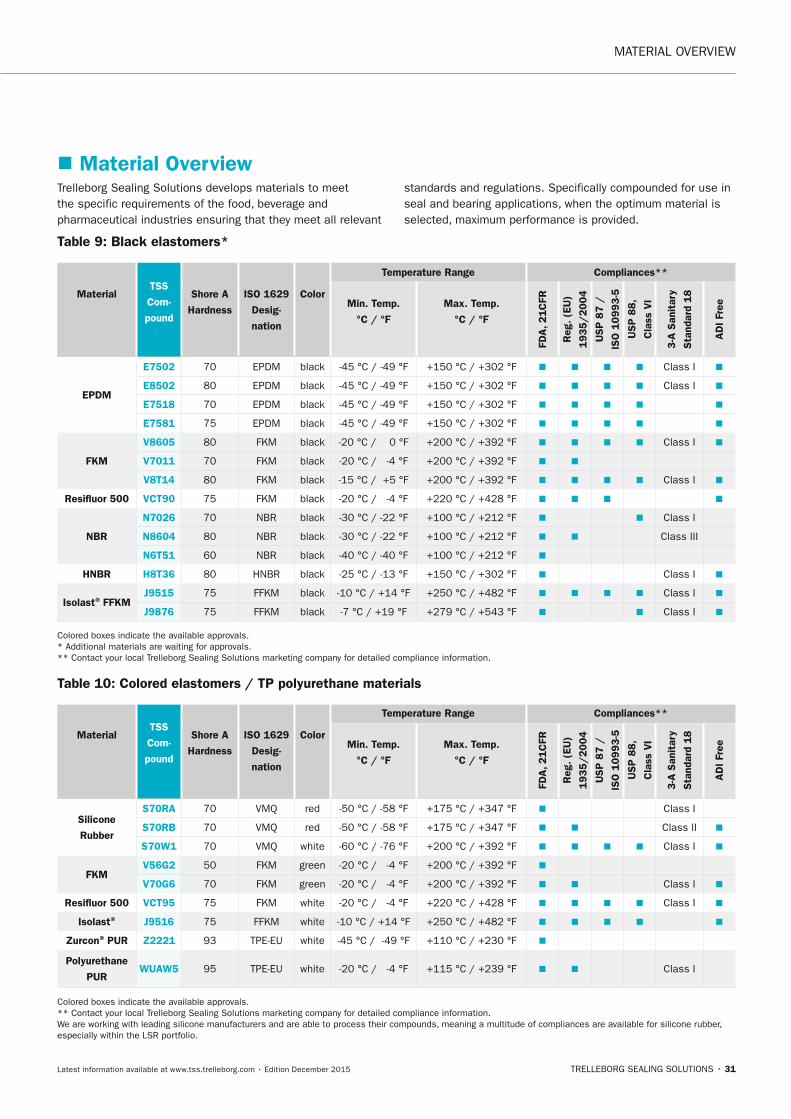
Table 9: Black elastomers*
Material
TSS
Com-
pound
Shore A
Hardness
ISO 1629
Desig-
nation
Color
Temperature Range Compliances**
Min. Temp.
°C / °F
Max. Temp.
°C / °F
FDA
, 21C
FR
Reg
. (E
U)
1935/2004
USP
87 /
ISO
10993-5
USP
88,
Cla
ss V
I
3-A
San
itar
y
Sta
ndar
d 18
AD
I Fr
ee
EPDM
E7502 70 EPDM black -45 °C / -49 °F +150 °C / +302 °F � � � � Class I �
E8502 80 EPDM black -45 °C / -49 °F +150 °C / +302 °F � � � � Class I �
E7518 70 EPDM black -45 °C / -49 °F +150 °C / +302 °F � � � � �
E7581 75 EPDM black -45 °C / -49 °F +150 °C / +302 °F � � � � �
FKM
V8605 80 FKM black -20 °C / 0 °F +200 °C / +392 °F � � � � Class I �
V7011 70 FKM black -20 °C / -4 °F +200 °C / +392 °F � �
V8T14 80 FKM black -15 °C / +5 °F +200 °C / +392 °F � � � � Class I �
Resifluor 500 VCT90 75 FKM black -20 °C / -4 °F +220 °C / +428 °F � � � �
nBR
n7026 70 NBR black -30 °C / -22 °F +100 °C / +212 °F � � Class I
n8604 80 NBR black -30 °C / -22 °F +100 °C / +212 °F � � Class III
n6T51 60 NBR black -40 °C / -40 °F +100 °C / +212 °F �
HnBR H8T36 80 HNBR black -25 °C / -13 °F +150 °C / +302 °F � Class I �
Isolast® FFKMJ9515 75 FFKM black -10 °C / +14 °F +250 °C / +482 °F � � � � Class I �
J9876 75 FFKM black -7 °C / +19 °F +279 °C / +543 °F � � Class I �
Colored boxes indicate the available approvals. * Additional materials are waiting for approvals. ** Contact your local Trelleborg Sealing Solutions marketing company for detailed compliance information.
Table 10: Colored elastomers / TP polyurethane materials
Material
TSS
Com-
pound
Shore A
Hardness
ISO 1629
Desig-
nation
Color
Temperature Range Compliances**
Min. Temp.
°C / °F
Max. Temp.
°C / °F
FDA
, 21C
FR
Reg
. (E
U)
19
35/2004
USP
87 /
ISO
10993-5
USP
88,
Cla
ss V
I
3-A
San
itar
y
Sta
ndar
d 18
AD
I Fr
ee
Silicone
Rubber
S70RA 70 VMQ red -50 °C / -58 °F +175 °C / +347 °F � Class I
S70RB 70 VMQ red -50 °C / -58 °F +175 °C / +347 °F � � Class II �
S70W1 70 VMQ white -60 °C / -76 °F +200 °C / +392 °F � � � � Class I �
FKMV56G2 50 FKM green -20 °C / -4 °F +200 °C / +392 °F �
V70G6 70 FKM green -20 °C / -4 °F +200 °C / +392 °F � � Class I �
Resifluor 500 VCT95 75 FKM white -20 °C / -4 °F +220 °C / +428 °F � � � � Class I �
Isolast® J9516 75 FFKM white -10 °C / +14 °F +250 °C / +482 °F � � � � �
Zurcon® PUR Z2221 93 TPE-EU white -45 °C / -49 °F +110 °C / +230 °F �
Polyurethane
PURWUAW5 95 TPE-EU white -20 °C / -4 °F +115 °C / +239 °F � � Class I
Colored boxes indicate the available approvals. ** Contact your local Trelleborg Sealing Solutions marketing company for detailed compliance information. We are working with leading silicone manufacturers and are able to process their compounds, meaning a multitude of compliances are available for silicone rubber, especially within the LSR portfolio.
Trelleborg Sealing Solutions develops materials to meet the specific requirements of the food, beverage and pharmaceutical industries ensuring that they meet all relevant
standards and regulations. Specifically compounded for use in seal and bearing applications, when the optimum material is selected, maximum performance is provided.
� Material Overview
FBP_neues_Layout_2015.indb 31 17.10.2016 13:35:09
MATERIAL OVERVIEW
32 • TRELLEBORG SEALING SOLUTIONS Latest information available at www.tss.trelleborg.com • Edition December 2015
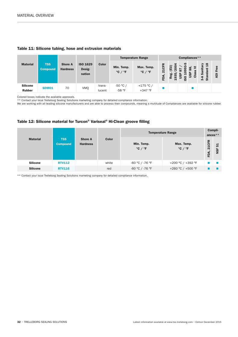
Table 11: Silicone tubing, hose and extrusion materials
Material
TSS
Compound
Shore A
Hardness
ISO 1629
Desig-
nation
Color
Temperature Range Compliances**
Min. Temp.
°C / °F
Max. Temp.
°C / °F
FDA
, 21C
FR
Reg
. (E
U)
1935/2004
USP
87 /
ISO
10993-5
USP
88,
Cla
ss V
I
3-A
San
itar
y
Sta
ndar
d 18
AD
I Fr
ee
Silicone
RubberSDM01 70 VMQ
trans-
lucent
-50 °C /
-58 °F
+175 °C /
+347 °F� �
Colored boxes indicate the available approvals. ** Contact your local Trelleborg Sealing Solutions marketing company for detailed compliance information. We are working with all leading silicone manufacturers and are able to process their compounds, meaning a multitude of Compliances are available for silicone rubber.
Table 12: Silicone material for Turcon® Variseal® Hi-Clean groove filling
Material
TSS
Compound
Shore A
Hardness
Color
Temperature RangeCompli-
ances**
Min. Temp.
°C / °F
Max. Temp.
°C / °F
FDA
, 21C
FR
nSF
51
Silicone RTV112 white -60 °C / -76 °F +200 °C / +392 °F � �
Silicone RTV116 red -60 °C / -76 °F +260 °C / +500 °F � �
** Contact your local Trelleborg Sealing Solutions marketing company for detailed compliance information.
FBP_neues_Layout_2015.indb 32 17.10.2016 13:35:09
MATERIAL OVERVIEW
TRELLEBORG SEALING SOLUTIONS • 33Latest information available at www.tss.trelleborg.com • Edition December 2015
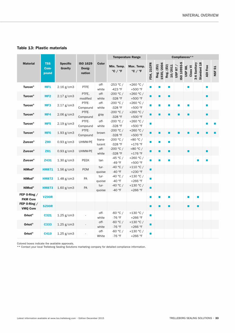
Table 13: Plastic materials
Material
TSS
Com-
pound
Specific
Gravity
ISO 1629
Desig-
nation
Color
Temperature Range Compliances**
Min. Temp.
°C / °F
Max. Temp.
°C / °F
FDA
, 21C
FR
Reg
. (E
U)
1935/2004
Reg
. (E
U)
10/2011
USP
87 /
ISO
10993-5
USP
88,
Cla
ss V
I
3-A
San
itar
y
Sta
ndar
d 18
AD
I Fr
ee
nSF
51
Turcon® MF1 2.16 g/cm3 PTFEoff-
white
-253 °C /
-423 °F
+260 °C /
+500 °F� � � � �
Turcon® MF2 2.17 g/cm3PTFE,
modified
off-
white
-200 °C /
-328 °F
+260 °C /
+500 °F� � � �
Turcon® MF3 2.17 g/cm3PTFE-
Compound
off-
white
-200 °C /
-328 °F
+260 °C /
+500 °F� � � � � �
Turcon® MF4 2.06 g/cm3PTFE-
Compoundgray
-200 °C /
-328 °F
+260 °C /
+500 °F� � � � � �
Turcon® MF5 2.19 g/cm3PTFE-
Compound
off-
white
-200 °C /
-328 °F
+260 °C /
+500 °F� � �
Turcon® MF6 1.93 g/cm3PTFE-
Compoundbrown
-200 °C /
-328 °F
+260 °C /
+500 °F� � � � � � � �
Zurcon® Z80 0.93 g/cm3 UHMW-PEtrans-
lucent
-200 °C /
-328 °F
+80 °C /
+176 °F� � �
Zurcon® Z81 0.93 g/cm3 UHMW-PEoff-
white
-200 °C /
-328 °F
+80 °C /
+176 °F� � � � �
Zurcon® Z431 1.30 g/cm3 PEEK tan -45 °C /
-49 °F
+260 °C /
+500 °F� � � � �
HiMod® HM871 1.56 g/cm3 POMtur-
quoise
-40 °C /
-40 °F
+110 °C /
+230 °F�
HiMod® HM872 1.48 g/cm3 PAtur-
quoise
-40 °C /
-40 °F
+130 °C /
+266 °F�
HiMod® HM873 1.60 g/cm3 PAtur-
quoise
-40 °C /
-40 °F
+130 °C /
+266 °F�
FEP O-Ring /
FKM CoreVZ00R � � � � �
FEP O-Ring /
VMQ CoreSZ00R � � � � �
Orkot® C321 1.25 g/cm3 -off-
white
-60 °C /
-76 °F
+130 °C /
+266 °F�
Orkot® C333 1.25 g/cm3 -off-
white
-60 °C /
-76 °F
+130 °C /
+266 °F�
Orkot® C410 1.25 g/cm3 -off-
White
-60 °C /
-76 °F
+130 °C /
+266 °F�
Colored boxes indicate the available approvals. ** Contact your local Trelleborg Sealing Solutions marketing company for detailed compliance information.
FBP_neues_Layout_2015.indb 33 17.10.2016 13:35:10
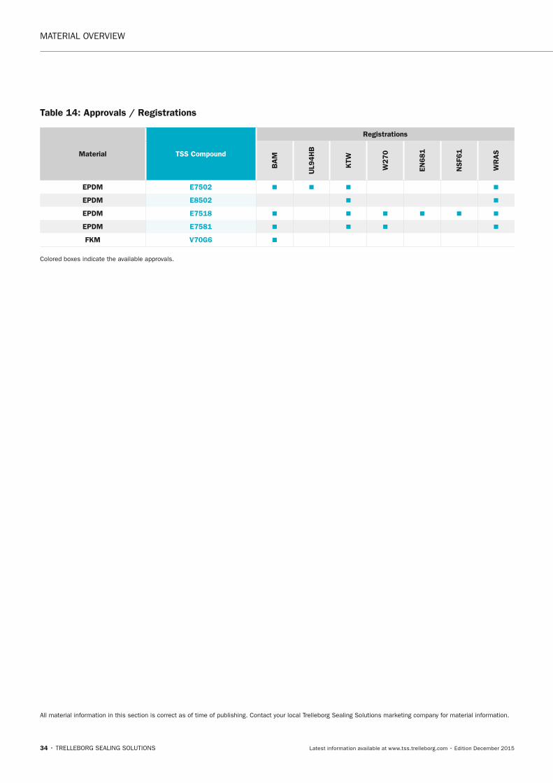
MATERIAL OVERVIEW
34 • TRELLEBORG SEALING SOLUTIONS Latest information available at www.tss.trelleborg.com • Edition December 2015
Table 14: Approvals / Registrations
Material TSS Compound
Registrations
BA
M
UL9
4H
B
KTW
W270
En681
nSF6
1
WR
AS
EPDM E7502 � � � �
EPDM E8502 � �
EPDM E7518 � � � � � �
EPDM E7581 � � � �
FKM V70G6 �
Colored boxes indicate the available approvals.
All material information in this section is correct as of time of publishing. Contact your local Trelleborg Sealing Solutions marketing company for material information.
FBP_neues_Layout_2015.indb 34 17.10.2016 13:35:10
Static SealS
TRELLEBORG SEALING SOLUTIONS • 35Latest information available at www.tss.trelleborg.com • Edition December 2015
StaticStaticSealsStaticSealsStaticStaticSealsStatic
FBP_neues_Layout_2015.indb 35 17.10.2016 13:35:13

36 • TRELLEBORG SEALING SOLUTIONS Latest information available at www.tss.trelleborg.com • Edition December 2015
STATIC SEALS
FBP_neues_Layout_2015.indb 36 17.10.2016 13:35:13
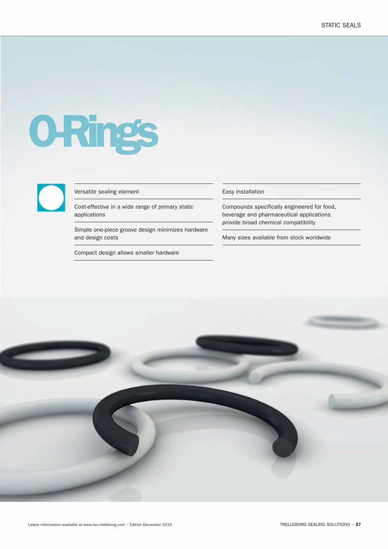
STATIC SEALS
TRELLEBORG SEALING SOLUTIONS • 37Latest information available at www.tss.trelleborg.com • Edition December 2015
O-RingsVersatile sealing element
Cost-effective in a wide range of primary static applications
Simple one-piece groove design minimizes hardware and design costs
Compact design allows smaller hardware
Easy installation
Compounds specifically engineered for food, beverage and pharmaceutical applications provide broad chemical compatibility
Many sizes available from stock worldwide
FBP_neues_Layout_2015.indb 37 17.10.2016 13:35:15

STATIC SEALS · O-Rings
38 • TRELLEBORG SEALING SOLUTIONS Latest information available at www.tss.trelleborg.com • Edition December 2015
FBP_neues_Layout_2015.indb 38 17.10.2016 13:35:15
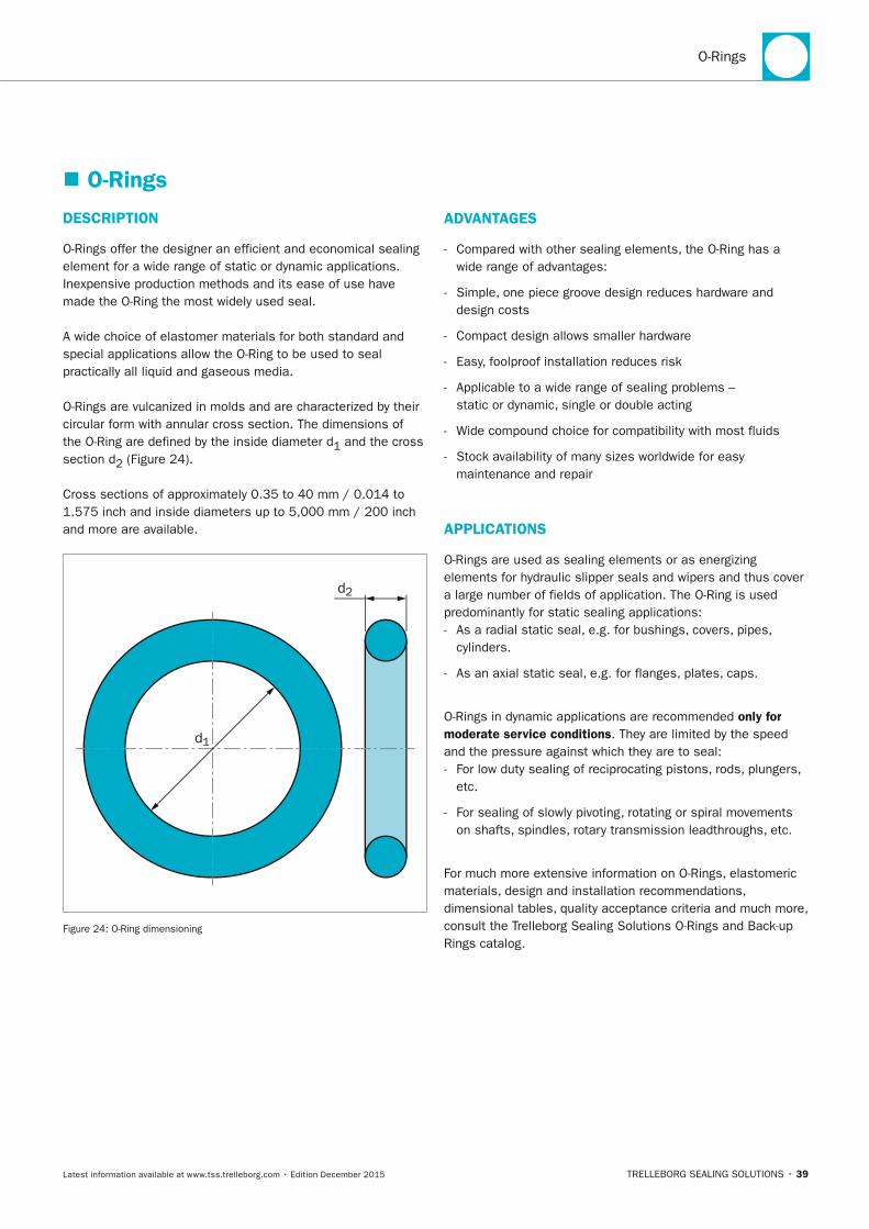
O-Rings
TRELLEBORG SEALING SOLUTIONS • 39Latest information available at www.tss.trelleborg.com • Edition December 2015
� O-Rings
DESCRIPTIOn
O-Rings offer the designer an efficient and economical sealing element for a wide range of static or dynamic applications.Inexpensive production methods and its ease of use have made the O-Ring the most widely used seal.
A wide choice of elastomer materials for both standard and special applications allow the O-Ring to be used to seal practically all liquid and gaseous media.
O-Rings are vulcanized in molds and are characterized by their circular form with annular cross section. The dimensions of the O-Ring are defined by the inside diameter d1 and the cross section d2 (Figure 24).
Cross sections of approximately 0.35 to 40 mm / 0.014 to 1.575 inch and inside diameters up to 5,000 mm / 200 inch and more are available.
d2
d1
Figure 24: O-Ring dimensioning
ADVAnTAGES
- Compared with other sealing elements, the O-Ring has a wide range of advantages:
- Simple, one piece groove design reduces hardware and design costs
- Compact design allows smaller hardware
- Easy, foolproof installation reduces risk
- Applicable to a wide range of sealing problems – static or dynamic, single or double acting
- Wide compound choice for compatibility with most fluids
- Stock availability of many sizes worldwide for easy maintenance and repair
APPLICATIOnS
O-Rings are used as sealing elements or as energizing elements for hydraulic slipper seals and wipers and thus cover a large number of fields of application. The O-Ring is used predominantly for static sealing applications: - As a radial static seal, e.g. for bushings, covers, pipes,
cylinders.
- As an axial static seal, e.g. for flanges, plates, caps.
O-Rings in dynamic applications are recommended only for moderate service conditions. They are limited by the speed and the pressure against which they are to seal: - For low duty sealing of reciprocating pistons, rods, plungers,
etc.
- For sealing of slowly pivoting, rotating or spiral movements on shafts, spindles, rotary transmission leadthroughs, etc.
For much more extensive information on O-Rings, elastomeric materials, design and installation recommendations, dimensional tables, quality acceptance criteria and much more, consult the Trelleborg Sealing Solutions O-Rings and Back-up Rings catalog.
FBP_neues_Layout_2015.indb 39 17.10.2016 13:35:16
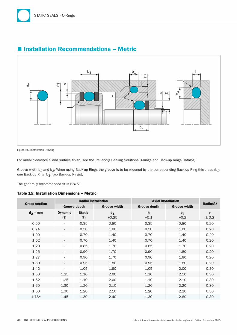
STATIC SEALS · O-Rings
40 • TRELLEBORG SEALING SOLUTIONS Latest information available at www.tss.trelleborg.com • Edition December 2015
� Installation Recommendations – Metric
b3 b1 h
b2
d 2
b 4
(t)
(t)s
r
r
r
(t) s
Figure 25: Installation Drawing
For radial clearance S and surface finish, see the Trelleborg Sealing Solutions O-Rings and Back-up Rings Catalog.
Groove width b2 and b3: When using Back-up Rings the groove is to be widened by the corresponding Back-up Ring thickness (b2: one Back-up Ring, b3: two Back-up Rings).
The generally recommended fit is H8/f7.
Table 15: Installation Dimensions – Metric
Cross sectionRadial installation Axial installation
Radius1)Groove depth Groove width Groove depth Groove width
d2 – mm Dynamic (t)
Static (t)
b1 +0.25
h +0.1
b4 +0.2
r ± 0.2
0.50 - 0.35 0.80 0.35 0.80 0.20
0.74 - 0.50 1.00 0.50 1.00 0.20
1.00 - 0.70 1.40 0.70 1.40 0.20
1.02 - 0.70 1.40 0.70 1.40 0.20
1.20 - 0.85 1.70 0.85 1.70 0.20
1.25 - 0.90 1.70 0.90 1.80 0.20
1.27 - 0.90 1.70 0.90 1.80 0.20
1.30 - 0.95 1.80 0.95 1.80 0.20
1.42 - 1.05 1.90 1.05 2.00 0.30
1.50 1.25 1.10 2.00 1.10 2.10 0.30
1.52 1.25 1.10 2.00 1.10 2.10 0.30
1.60 1.30 1.20 2.10 1.20 2.20 0.30
1.63 1.30 1.20 2.10 1.20 2.20 0.30
1.78* 1.45 1.30 2.40 1.30 2.60 0.30
FBP_neues_Layout_2015.indb 40 17.10.2016 13:35:16
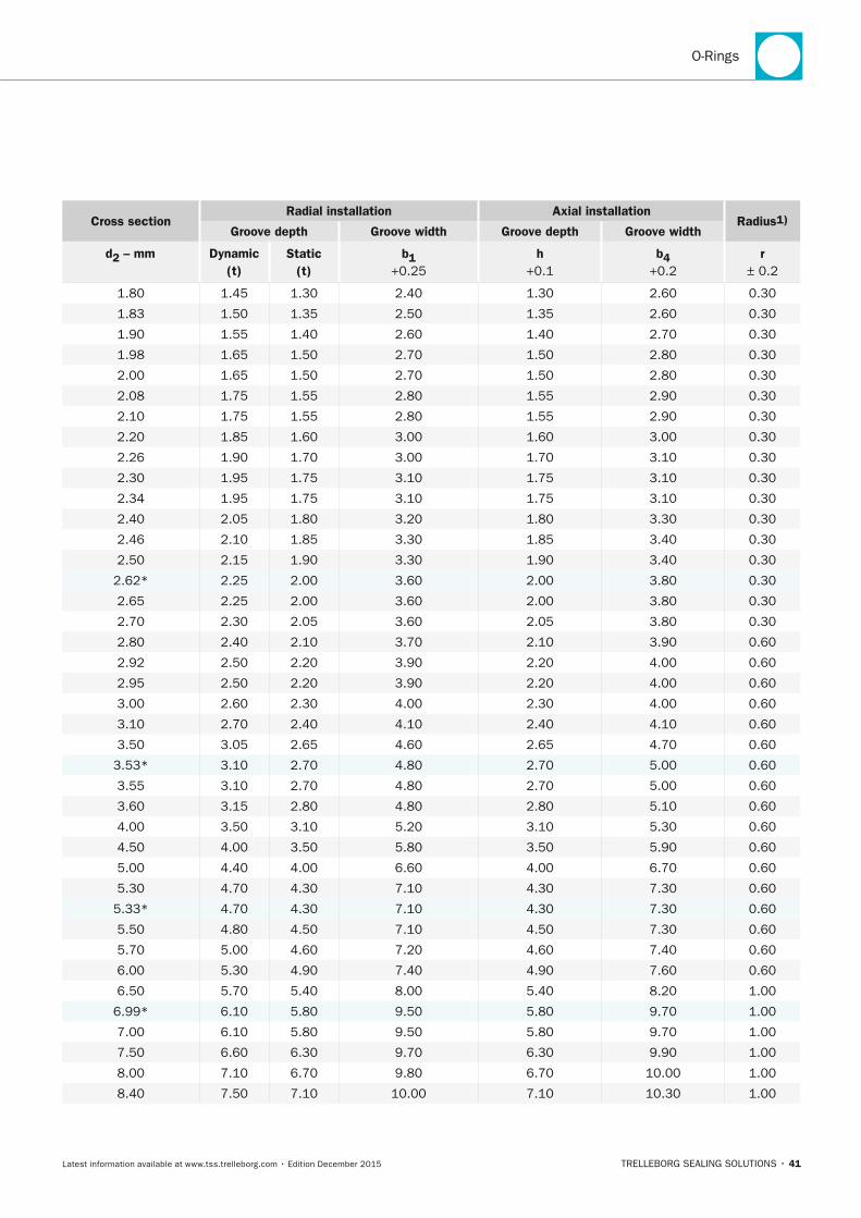
O-Rings
TRELLEBORG SEALING SOLUTIONS • 41Latest information available at www.tss.trelleborg.com • Edition December 2015
Cross sectionRadial installation Axial installation
Radius1)Groove depth Groove width Groove depth Groove width
d2 – mm Dynamic (t)
Static (t)
b1 +0.25
h +0.1
b4 +0.2
r ± 0.2
1.80 1.45 1.30 2.40 1.30 2.60 0.30
1.83 1.50 1.35 2.50 1.35 2.60 0.30
1.90 1.55 1.40 2.60 1.40 2.70 0.30
1.98 1.65 1.50 2.70 1.50 2.80 0.30
2.00 1.65 1.50 2.70 1.50 2.80 0.30
2.08 1.75 1.55 2.80 1.55 2.90 0.30
2.10 1.75 1.55 2.80 1.55 2.90 0.30
2.20 1.85 1.60 3.00 1.60 3.00 0.30
2.26 1.90 1.70 3.00 1.70 3.10 0.30
2.30 1.95 1.75 3.10 1.75 3.10 0.30
2.34 1.95 1.75 3.10 1.75 3.10 0.30
2.40 2.05 1.80 3.20 1.80 3.30 0.30
2.46 2.10 1.85 3.30 1.85 3.40 0.30
2.50 2.15 1.90 3.30 1.90 3.40 0.30
2.62* 2.25 2.00 3.60 2.00 3.80 0.30
2.65 2.25 2.00 3.60 2.00 3.80 0.30
2.70 2.30 2.05 3.60 2.05 3.80 0.30
2.80 2.40 2.10 3.70 2.10 3.90 0.60
2.92 2.50 2.20 3.90 2.20 4.00 0.60
2.95 2.50 2.20 3.90 2.20 4.00 0.60
3.00 2.60 2.30 4.00 2.30 4.00 0.60
3.10 2.70 2.40 4.10 2.40 4.10 0.60
3.50 3.05 2.65 4.60 2.65 4.70 0.60
3.53* 3.10 2.70 4.80 2.70 5.00 0.60
3.55 3.10 2.70 4.80 2.70 5.00 0.60
3.60 3.15 2.80 4.80 2.80 5.10 0.60
4.00 3.50 3.10 5.20 3.10 5.30 0.60
4.50 4.00 3.50 5.80 3.50 5.90 0.60
5.00 4.40 4.00 6.60 4.00 6.70 0.60
5.30 4.70 4.30 7.10 4.30 7.30 0.60
5.33* 4.70 4.30 7.10 4.30 7.30 0.60
5.50 4.80 4.50 7.10 4.50 7.30 0.60
5.70 5.00 4.60 7.20 4.60 7.40 0.60
6.00 5.30 4.90 7.40 4.90 7.60 0.60
6.50 5.70 5.40 8.00 5.40 8.20 1.00
6.99* 6.10 5.80 9.50 5.80 9.70 1.00
7.00 6.10 5.80 9.50 5.80 9.70 1.00
7.50 6.60 6.30 9.70 6.30 9.90 1.00
8.00 7.10 6.70 9.80 6.70 10.00 1.00
8.40 7.50 7.10 10.00 7.10 10.30 1.00
FBP_neues_Layout_2015.indb 41 17.10.2016 13:35:17
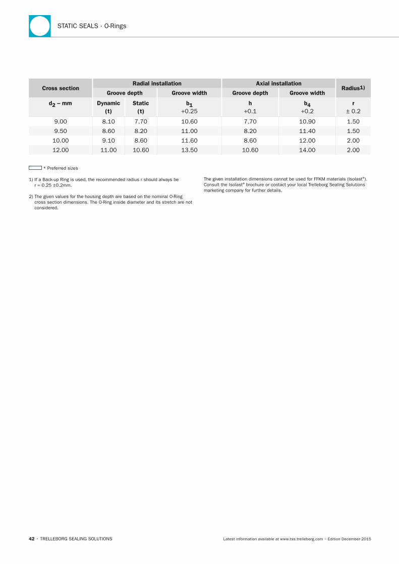
STATIC SEALS · O-Rings
42 • TRELLEBORG SEALING SOLUTIONS Latest information available at www.tss.trelleborg.com • Edition December 2015
* Preferred sizes
1) If a Back-up Ring is used, the recommended radius r should always be r = 0.25 ±0.2mm.
2) The given values for the housing depth are based on the nominal O-Ring cross section dimensions. The O-Ring inside diameter and its stretch are not considered.
The given installation dimensions cannot be used for FFKM materials (Isolast®). Consult the Isolast® brochure or contact your local Trelleborg Sealing Solutions marketing company for further details.
Cross sectionRadial installation Axial installation
Radius1)Groove depth Groove width Groove depth Groove width
d2 – mm Dynamic (t)
Static (t)
b1 +0.25
h +0.1
b4 +0.2
r ± 0.2
9.00 8.10 7.70 10.60 7.70 10.90 1.50
9.50 8.60 8.20 11.00 8.20 11.40 1.50
10.00 9.10 8.60 11.60 8.60 12.00 2.00
12.00 11.00 10.60 13.50 10.60 14.00 2.00
FBP_neues_Layout_2015.indb 42 17.10.2016 13:35:17
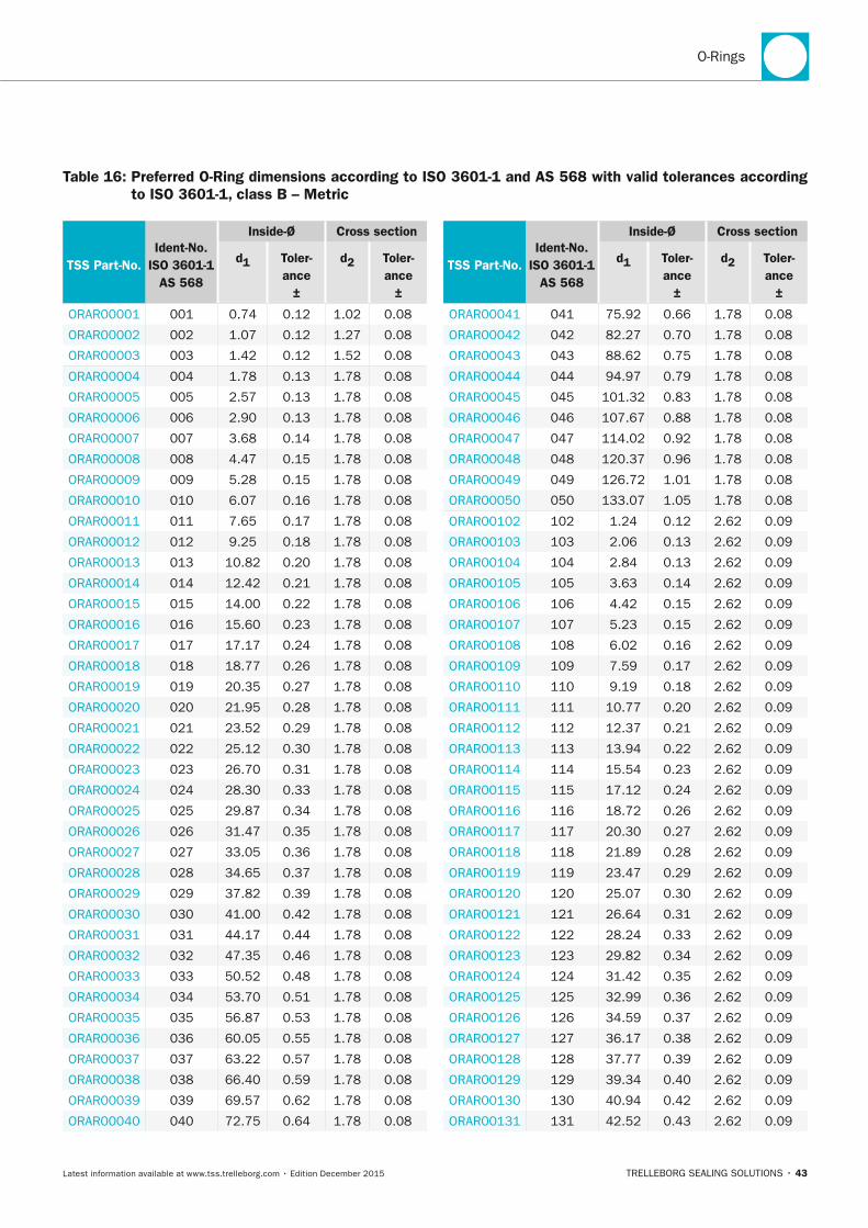
O-Rings
TRELLEBORG SEALING SOLUTIONS • 43Latest information available at www.tss.trelleborg.com • Edition December 2015
Table 16: Preferred O-Ring dimensions according to ISO 3601-1 and AS 568 with valid tolerances according to ISO 3601-1, class B – Metric
TSS Part-no.Ident-no.
ISO 3601-1 AS 568
Inside-Ø Cross section
d1 Toler-ance
±
d2 Toler-ance
±
ORAR00001 001 0.74 0.12 1.02 0.08
ORAR00002 002 1.07 0.12 1.27 0.08
ORAR00003 003 1.42 0.12 1.52 0.08
ORAR00004 004 1.78 0.13 1.78 0.08
ORAR00005 005 2.57 0.13 1.78 0.08
ORAR00006 006 2.90 0.13 1.78 0.08
ORAR00007 007 3.68 0.14 1.78 0.08
ORAR00008 008 4.47 0.15 1.78 0.08
ORAR00009 009 5.28 0.15 1.78 0.08
ORAR00010 010 6.07 0.16 1.78 0.08
ORAR00011 011 7.65 0.17 1.78 0.08
ORAR00012 012 9.25 0.18 1.78 0.08
ORAR00013 013 10.82 0.20 1.78 0.08
ORAR00014 014 12.42 0.21 1.78 0.08
ORAR00015 015 14.00 0.22 1.78 0.08
ORAR00016 016 15.60 0.23 1.78 0.08
ORAR00017 017 17.17 0.24 1.78 0.08
ORAR00018 018 18.77 0.26 1.78 0.08
ORAR00019 019 20.35 0.27 1.78 0.08
ORAR00020 020 21.95 0.28 1.78 0.08
ORAR00021 021 23.52 0.29 1.78 0.08
ORAR00022 022 25.12 0.30 1.78 0.08
ORAR00023 023 26.70 0.31 1.78 0.08
ORAR00024 024 28.30 0.33 1.78 0.08
ORAR00025 025 29.87 0.34 1.78 0.08
ORAR00026 026 31.47 0.35 1.78 0.08
ORAR00027 027 33.05 0.36 1.78 0.08
ORAR00028 028 34.65 0.37 1.78 0.08
ORAR00029 029 37.82 0.39 1.78 0.08
ORAR00030 030 41.00 0.42 1.78 0.08
ORAR00031 031 44.17 0.44 1.78 0.08
ORAR00032 032 47.35 0.46 1.78 0.08
ORAR00033 033 50.52 0.48 1.78 0.08
ORAR00034 034 53.70 0.51 1.78 0.08
ORAR00035 035 56.87 0.53 1.78 0.08
ORAR00036 036 60.05 0.55 1.78 0.08
ORAR00037 037 63.22 0.57 1.78 0.08
ORAR00038 038 66.40 0.59 1.78 0.08
ORAR00039 039 69.57 0.62 1.78 0.08
ORAR00040 040 72.75 0.64 1.78 0.08
TSS Part-no.Ident-no.
ISO 3601-1 AS 568
Inside-Ø Cross section
d1 Toler-ance
±
d2 Toler-ance
±
ORAR00041 041 75.92 0.66 1.78 0.08
ORAR00042 042 82.27 0.70 1.78 0.08
ORAR00043 043 88.62 0.75 1.78 0.08
ORAR00044 044 94.97 0.79 1.78 0.08
ORAR00045 045 101.32 0.83 1.78 0.08
ORAR00046 046 107.67 0.88 1.78 0.08
ORAR00047 047 114.02 0.92 1.78 0.08
ORAR00048 048 120.37 0.96 1.78 0.08
ORAR00049 049 126.72 1.01 1.78 0.08
ORAR00050 050 133.07 1.05 1.78 0.08
ORAR00102 102 1.24 0.12 2.62 0.09
ORAR00103 103 2.06 0.13 2.62 0.09
ORAR00104 104 2.84 0.13 2.62 0.09
ORAR00105 105 3.63 0.14 2.62 0.09
ORAR00106 106 4.42 0.15 2.62 0.09
ORAR00107 107 5.23 0.15 2.62 0.09
ORAR00108 108 6.02 0.16 2.62 0.09
ORAR00109 109 7.59 0.17 2.62 0.09
ORAR00110 110 9.19 0.18 2.62 0.09
ORAR00111 111 10.77 0.20 2.62 0.09
ORAR00112 112 12.37 0.21 2.62 0.09
ORAR00113 113 13.94 0.22 2.62 0.09
ORAR00114 114 15.54 0.23 2.62 0.09
ORAR00115 115 17.12 0.24 2.62 0.09
ORAR00116 116 18.72 0.26 2.62 0.09
ORAR00117 117 20.30 0.27 2.62 0.09
ORAR00118 118 21.89 0.28 2.62 0.09
ORAR00119 119 23.47 0.29 2.62 0.09
ORAR00120 120 25.07 0.30 2.62 0.09
ORAR00121 121 26.64 0.31 2.62 0.09
ORAR00122 122 28.24 0.33 2.62 0.09
ORAR00123 123 29.82 0.34 2.62 0.09
ORAR00124 124 31.42 0.35 2.62 0.09
ORAR00125 125 32.99 0.36 2.62 0.09
ORAR00126 126 34.59 0.37 2.62 0.09
ORAR00127 127 36.17 0.38 2.62 0.09
ORAR00128 128 37.77 0.39 2.62 0.09
ORAR00129 129 39.34 0.40 2.62 0.09
ORAR00130 130 40.94 0.42 2.62 0.09
ORAR00131 131 42.52 0.43 2.62 0.09
FBP_neues_Layout_2015.indb 43 17.10.2016 13:35:18
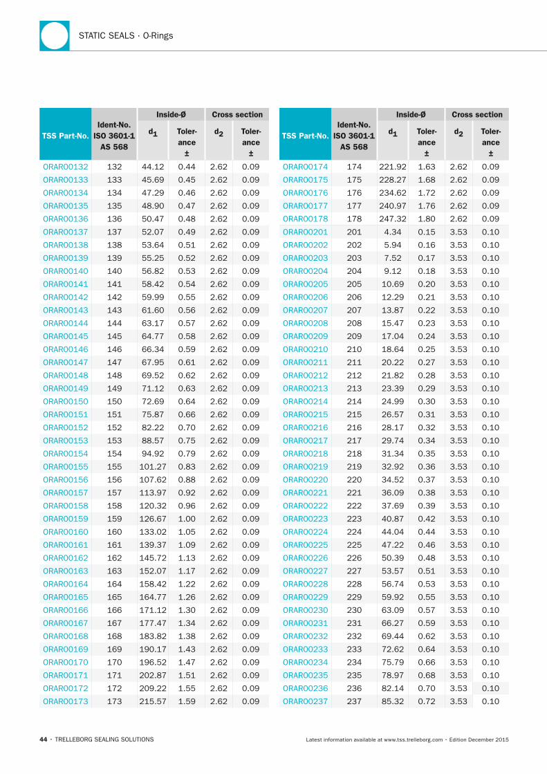
STATIC SEALS · O-Rings
44 • TRELLEBORG SEALING SOLUTIONS Latest information available at www.tss.trelleborg.com • Edition December 2015
TSS Part-no.Ident-no.
ISO 3601-1 AS 568
Inside-Ø Cross section
d1 Toler-ance
±
d2 Toler-ance
±
ORAR00132 132 44.12 0.44 2.62 0.09
ORAR00133 133 45.69 0.45 2.62 0.09
ORAR00134 134 47.29 0.46 2.62 0.09
ORAR00135 135 48.90 0.47 2.62 0.09
ORAR00136 136 50.47 0.48 2.62 0.09
ORAR00137 137 52.07 0.49 2.62 0.09
ORAR00138 138 53.64 0.51 2.62 0.09
ORAR00139 139 55.25 0.52 2.62 0.09
ORAR00140 140 56.82 0.53 2.62 0.09
ORAR00141 141 58.42 0.54 2.62 0.09
ORAR00142 142 59.99 0.55 2.62 0.09
ORAR00143 143 61.60 0.56 2.62 0.09
ORAR00144 144 63.17 0.57 2.62 0.09
ORAR00145 145 64.77 0.58 2.62 0.09
ORAR00146 146 66.34 0.59 2.62 0.09
ORAR00147 147 67.95 0.61 2.62 0.09
ORAR00148 148 69.52 0.62 2.62 0.09
ORAR00149 149 71.12 0.63 2.62 0.09
ORAR00150 150 72.69 0.64 2.62 0.09
ORAR00151 151 75.87 0.66 2.62 0.09
ORAR00152 152 82.22 0.70 2.62 0.09
ORAR00153 153 88.57 0.75 2.62 0.09
ORAR00154 154 94.92 0.79 2.62 0.09
ORAR00155 155 101.27 0.83 2.62 0.09
ORAR00156 156 107.62 0.88 2.62 0.09
ORAR00157 157 113.97 0.92 2.62 0.09
ORAR00158 158 120.32 0.96 2.62 0.09
ORAR00159 159 126.67 1.00 2.62 0.09
ORAR00160 160 133.02 1.05 2.62 0.09
ORAR00161 161 139.37 1.09 2.62 0.09
ORAR00162 162 145.72 1.13 2.62 0.09
ORAR00163 163 152.07 1.17 2.62 0.09
ORAR00164 164 158.42 1.22 2.62 0.09
ORAR00165 165 164.77 1.26 2.62 0.09
ORAR00166 166 171.12 1.30 2.62 0.09
ORAR00167 167 177.47 1.34 2.62 0.09
ORAR00168 168 183.82 1.38 2.62 0.09
ORAR00169 169 190.17 1.43 2.62 0.09
ORAR00170 170 196.52 1.47 2.62 0.09
ORAR00171 171 202.87 1.51 2.62 0.09
ORAR00172 172 209.22 1.55 2.62 0.09
ORAR00173 173 215.57 1.59 2.62 0.09
TSS Part-no.Ident-no.
ISO 3601-1 AS 568
Inside-Ø Cross section
d1 Toler-ance
±
d2 Toler-ance
±
ORAR00174 174 221.92 1.63 2.62 0.09
ORAR00175 175 228.27 1.68 2.62 0.09
ORAR00176 176 234.62 1.72 2.62 0.09
ORAR00177 177 240.97 1.76 2.62 0.09
ORAR00178 178 247.32 1.80 2.62 0.09
ORAR00201 201 4.34 0.15 3.53 0.10
ORAR00202 202 5.94 0.16 3.53 0.10
ORAR00203 203 7.52 0.17 3.53 0.10
ORAR00204 204 9.12 0.18 3.53 0.10
ORAR00205 205 10.69 0.20 3.53 0.10
ORAR00206 206 12.29 0.21 3.53 0.10
ORAR00207 207 13.87 0.22 3.53 0.10
ORAR00208 208 15.47 0.23 3.53 0.10
ORAR00209 209 17.04 0.24 3.53 0.10
ORAR00210 210 18.64 0.25 3.53 0.10
ORAR00211 211 20.22 0.27 3.53 0.10
ORAR00212 212 21.82 0.28 3.53 0.10
ORAR00213 213 23.39 0.29 3.53 0.10
ORAR00214 214 24.99 0.30 3.53 0.10
ORAR00215 215 26.57 0.31 3.53 0.10
ORAR00216 216 28.17 0.32 3.53 0.10
ORAR00217 217 29.74 0.34 3.53 0.10
ORAR00218 218 31.34 0.35 3.53 0.10
ORAR00219 219 32.92 0.36 3.53 0.10
ORAR00220 220 34.52 0.37 3.53 0.10
ORAR00221 221 36.09 0.38 3.53 0.10
ORAR00222 222 37.69 0.39 3.53 0.10
ORAR00223 223 40.87 0.42 3.53 0.10
ORAR00224 224 44.04 0.44 3.53 0.10
ORAR00225 225 47.22 0.46 3.53 0.10
ORAR00226 226 50.39 0.48 3.53 0.10
ORAR00227 227 53.57 0.51 3.53 0.10
ORAR00228 228 56.74 0.53 3.53 0.10
ORAR00229 229 59.92 0.55 3.53 0.10
ORAR00230 230 63.09 0.57 3.53 0.10
ORAR00231 231 66.27 0.59 3.53 0.10
ORAR00232 232 69.44 0.62 3.53 0.10
ORAR00233 233 72.62 0.64 3.53 0.10
ORAR00234 234 75.79 0.66 3.53 0.10
ORAR00235 235 78.97 0.68 3.53 0.10
ORAR00236 236 82.14 0.70 3.53 0.10
ORAR00237 237 85.32 0.72 3.53 0.10
FBP_neues_Layout_2015.indb 44 17.10.2016 13:35:18
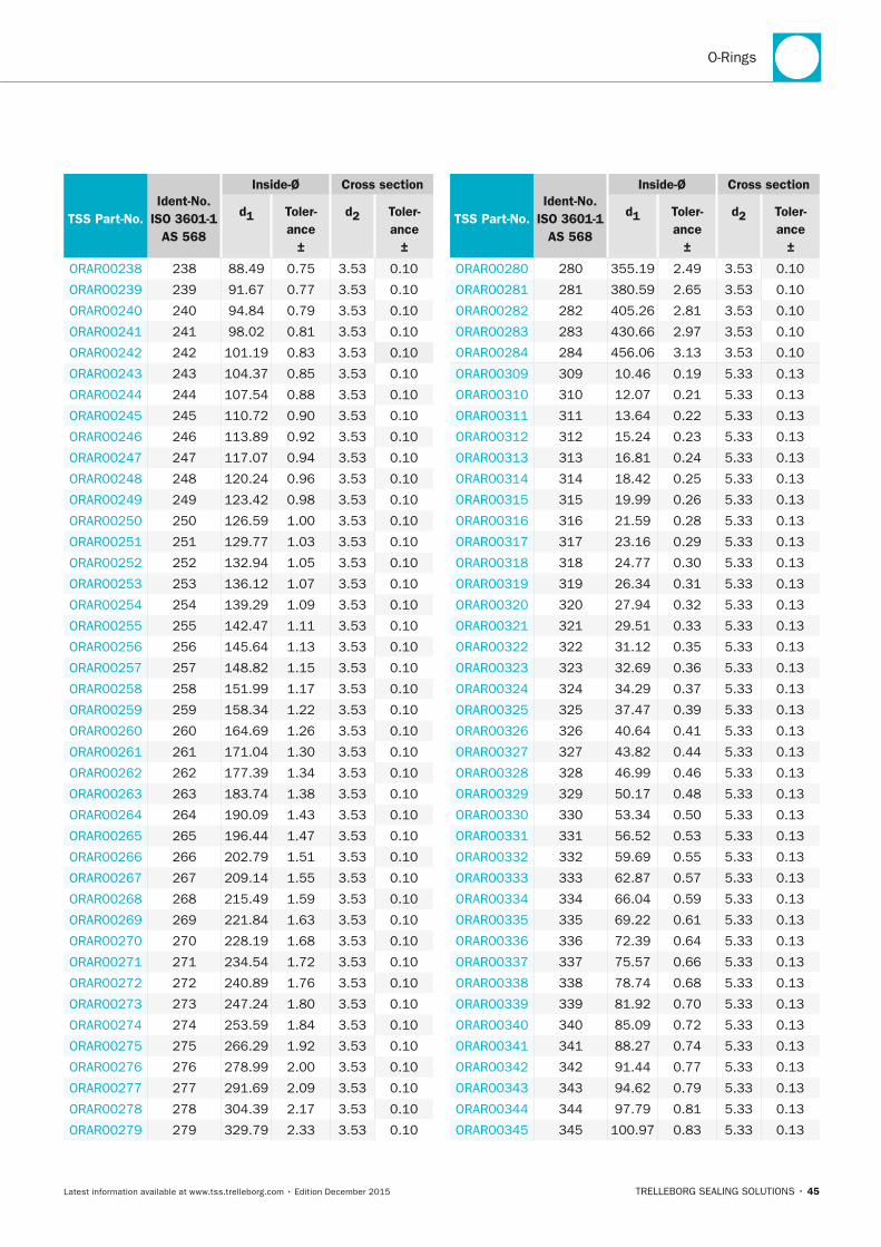
O-Rings
TRELLEBORG SEALING SOLUTIONS • 45Latest information available at www.tss.trelleborg.com • Edition December 2015
TSS Part-no.Ident-no.
ISO 3601-1 AS 568
Inside-Ø Cross section
d1 Toler-ance
±
d2 Toler-ance
±
ORAR00238 238 88.49 0.75 3.53 0.10
ORAR00239 239 91.67 0.77 3.53 0.10
ORAR00240 240 94.84 0.79 3.53 0.10
ORAR00241 241 98.02 0.81 3.53 0.10
ORAR00242 242 101.19 0.83 3.53 0.10
ORAR00243 243 104.37 0.85 3.53 0.10
ORAR00244 244 107.54 0.88 3.53 0.10
ORAR00245 245 110.72 0.90 3.53 0.10
ORAR00246 246 113.89 0.92 3.53 0.10
ORAR00247 247 117.07 0.94 3.53 0.10
ORAR00248 248 120.24 0.96 3.53 0.10
ORAR00249 249 123.42 0.98 3.53 0.10
ORAR00250 250 126.59 1.00 3.53 0.10
ORAR00251 251 129.77 1.03 3.53 0.10
ORAR00252 252 132.94 1.05 3.53 0.10
ORAR00253 253 136.12 1.07 3.53 0.10
ORAR00254 254 139.29 1.09 3.53 0.10
ORAR00255 255 142.47 1.11 3.53 0.10
ORAR00256 256 145.64 1.13 3.53 0.10
ORAR00257 257 148.82 1.15 3.53 0.10
ORAR00258 258 151.99 1.17 3.53 0.10
ORAR00259 259 158.34 1.22 3.53 0.10
ORAR00260 260 164.69 1.26 3.53 0.10
ORAR00261 261 171.04 1.30 3.53 0.10
ORAR00262 262 177.39 1.34 3.53 0.10
ORAR00263 263 183.74 1.38 3.53 0.10
ORAR00264 264 190.09 1.43 3.53 0.10
ORAR00265 265 196.44 1.47 3.53 0.10
ORAR00266 266 202.79 1.51 3.53 0.10
ORAR00267 267 209.14 1.55 3.53 0.10
ORAR00268 268 215.49 1.59 3.53 0.10
ORAR00269 269 221.84 1.63 3.53 0.10
ORAR00270 270 228.19 1.68 3.53 0.10
ORAR00271 271 234.54 1.72 3.53 0.10
ORAR00272 272 240.89 1.76 3.53 0.10
ORAR00273 273 247.24 1.80 3.53 0.10
ORAR00274 274 253.59 1.84 3.53 0.10
ORAR00275 275 266.29 1.92 3.53 0.10
ORAR00276 276 278.99 2.00 3.53 0.10
ORAR00277 277 291.69 2.09 3.53 0.10
ORAR00278 278 304.39 2.17 3.53 0.10
ORAR00279 279 329.79 2.33 3.53 0.10
TSS Part-no.Ident-no.
ISO 3601-1 AS 568
Inside-Ø Cross section
d1 Toler-ance
±
d2 Toler-ance
±
ORAR00280 280 355.19 2.49 3.53 0.10
ORAR00281 281 380.59 2.65 3.53 0.10
ORAR00282 282 405.26 2.81 3.53 0.10
ORAR00283 283 430.66 2.97 3.53 0.10
ORAR00284 284 456.06 3.13 3.53 0.10
ORAR00309 309 10.46 0.19 5.33 0.13
ORAR00310 310 12.07 0.21 5.33 0.13
ORAR00311 311 13.64 0.22 5.33 0.13
ORAR00312 312 15.24 0.23 5.33 0.13
ORAR00313 313 16.81 0.24 5.33 0.13
ORAR00314 314 18.42 0.25 5.33 0.13
ORAR00315 315 19.99 0.26 5.33 0.13
ORAR00316 316 21.59 0.28 5.33 0.13
ORAR00317 317 23.16 0.29 5.33 0.13
ORAR00318 318 24.77 0.30 5.33 0.13
ORAR00319 319 26.34 0.31 5.33 0.13
ORAR00320 320 27.94 0.32 5.33 0.13
ORAR00321 321 29.51 0.33 5.33 0.13
ORAR00322 322 31.12 0.35 5.33 0.13
ORAR00323 323 32.69 0.36 5.33 0.13
ORAR00324 324 34.29 0.37 5.33 0.13
ORAR00325 325 37.47 0.39 5.33 0.13
ORAR00326 326 40.64 0.41 5.33 0.13
ORAR00327 327 43.82 0.44 5.33 0.13
ORAR00328 328 46.99 0.46 5.33 0.13
ORAR00329 329 50.17 0.48 5.33 0.13
ORAR00330 330 53.34 0.50 5.33 0.13
ORAR00331 331 56.52 0.53 5.33 0.13
ORAR00332 332 59.69 0.55 5.33 0.13
ORAR00333 333 62.87 0.57 5.33 0.13
ORAR00334 334 66.04 0.59 5.33 0.13
ORAR00335 335 69.22 0.61 5.33 0.13
ORAR00336 336 72.39 0.64 5.33 0.13
ORAR00337 337 75.57 0.66 5.33 0.13
ORAR00338 338 78.74 0.68 5.33 0.13
ORAR00339 339 81.92 0.70 5.33 0.13
ORAR00340 340 85.09 0.72 5.33 0.13
ORAR00341 341 88.27 0.74 5.33 0.13
ORAR00342 342 91.44 0.77 5.33 0.13
ORAR00343 343 94.62 0.79 5.33 0.13
ORAR00344 344 97.79 0.81 5.33 0.13
ORAR00345 345 100.97 0.83 5.33 0.13
FBP_neues_Layout_2015.indb 45 17.10.2016 13:35:19
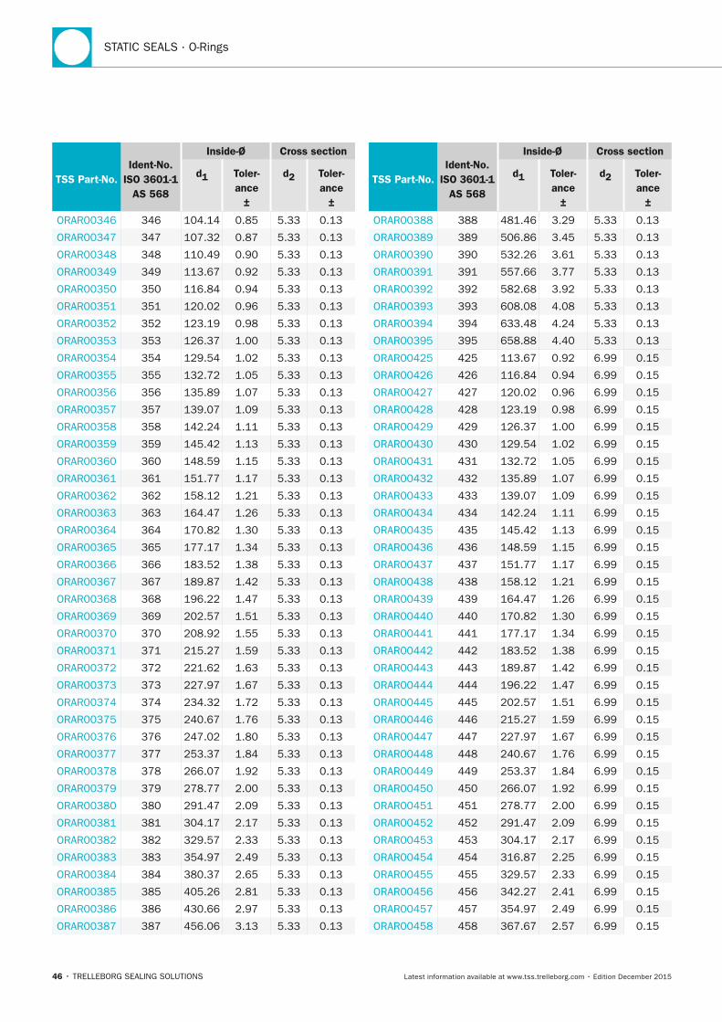
STATIC SEALS · O-Rings
46 • TRELLEBORG SEALING SOLUTIONS Latest information available at www.tss.trelleborg.com • Edition December 2015
TSS Part-no.Ident-no.
ISO 3601-1 AS 568
Inside-Ø Cross section
d1 Toler-ance
±
d2 Toler-ance
±
ORAR00346 346 104.14 0.85 5.33 0.13
ORAR00347 347 107.32 0.87 5.33 0.13
ORAR00348 348 110.49 0.90 5.33 0.13
ORAR00349 349 113.67 0.92 5.33 0.13
ORAR00350 350 116.84 0.94 5.33 0.13
ORAR00351 351 120.02 0.96 5.33 0.13
ORAR00352 352 123.19 0.98 5.33 0.13
ORAR00353 353 126.37 1.00 5.33 0.13
ORAR00354 354 129.54 1.02 5.33 0.13
ORAR00355 355 132.72 1.05 5.33 0.13
ORAR00356 356 135.89 1.07 5.33 0.13
ORAR00357 357 139.07 1.09 5.33 0.13
ORAR00358 358 142.24 1.11 5.33 0.13
ORAR00359 359 145.42 1.13 5.33 0.13
ORAR00360 360 148.59 1.15 5.33 0.13
ORAR00361 361 151.77 1.17 5.33 0.13
ORAR00362 362 158.12 1.21 5.33 0.13
ORAR00363 363 164.47 1.26 5.33 0.13
ORAR00364 364 170.82 1.30 5.33 0.13
ORAR00365 365 177.17 1.34 5.33 0.13
ORAR00366 366 183.52 1.38 5.33 0.13
ORAR00367 367 189.87 1.42 5.33 0.13
ORAR00368 368 196.22 1.47 5.33 0.13
ORAR00369 369 202.57 1.51 5.33 0.13
ORAR00370 370 208.92 1.55 5.33 0.13
ORAR00371 371 215.27 1.59 5.33 0.13
ORAR00372 372 221.62 1.63 5.33 0.13
ORAR00373 373 227.97 1.67 5.33 0.13
ORAR00374 374 234.32 1.72 5.33 0.13
ORAR00375 375 240.67 1.76 5.33 0.13
ORAR00376 376 247.02 1.80 5.33 0.13
ORAR00377 377 253.37 1.84 5.33 0.13
ORAR00378 378 266.07 1.92 5.33 0.13
ORAR00379 379 278.77 2.00 5.33 0.13
ORAR00380 380 291.47 2.09 5.33 0.13
ORAR00381 381 304.17 2.17 5.33 0.13
ORAR00382 382 329.57 2.33 5.33 0.13
ORAR00383 383 354.97 2.49 5.33 0.13
ORAR00384 384 380.37 2.65 5.33 0.13
ORAR00385 385 405.26 2.81 5.33 0.13
ORAR00386 386 430.66 2.97 5.33 0.13
ORAR00387 387 456.06 3.13 5.33 0.13
TSS Part-no.Ident-no.
ISO 3601-1 AS 568
Inside-Ø Cross section
d1 Toler-ance
±
d2 Toler-ance
±
ORAR00388 388 481.46 3.29 5.33 0.13
ORAR00389 389 506.86 3.45 5.33 0.13
ORAR00390 390 532.26 3.61 5.33 0.13
ORAR00391 391 557.66 3.77 5.33 0.13
ORAR00392 392 582.68 3.92 5.33 0.13
ORAR00393 393 608.08 4.08 5.33 0.13
ORAR00394 394 633.48 4.24 5.33 0.13
ORAR00395 395 658.88 4.40 5.33 0.13
ORAR00425 425 113.67 0.92 6.99 0.15
ORAR00426 426 116.84 0.94 6.99 0.15
ORAR00427 427 120.02 0.96 6.99 0.15
ORAR00428 428 123.19 0.98 6.99 0.15
ORAR00429 429 126.37 1.00 6.99 0.15
ORAR00430 430 129.54 1.02 6.99 0.15
ORAR00431 431 132.72 1.05 6.99 0.15
ORAR00432 432 135.89 1.07 6.99 0.15
ORAR00433 433 139.07 1.09 6.99 0.15
ORAR00434 434 142.24 1.11 6.99 0.15
ORAR00435 435 145.42 1.13 6.99 0.15
ORAR00436 436 148.59 1.15 6.99 0.15
ORAR00437 437 151.77 1.17 6.99 0.15
ORAR00438 438 158.12 1.21 6.99 0.15
ORAR00439 439 164.47 1.26 6.99 0.15
ORAR00440 440 170.82 1.30 6.99 0.15
ORAR00441 441 177.17 1.34 6.99 0.15
ORAR00442 442 183.52 1.38 6.99 0.15
ORAR00443 443 189.87 1.42 6.99 0.15
ORAR00444 444 196.22 1.47 6.99 0.15
ORAR00445 445 202.57 1.51 6.99 0.15
ORAR00446 446 215.27 1.59 6.99 0.15
ORAR00447 447 227.97 1.67 6.99 0.15
ORAR00448 448 240.67 1.76 6.99 0.15
ORAR00449 449 253.37 1.84 6.99 0.15
ORAR00450 450 266.07 1.92 6.99 0.15
ORAR00451 451 278.77 2.00 6.99 0.15
ORAR00452 452 291.47 2.09 6.99 0.15
ORAR00453 453 304.17 2.17 6.99 0.15
ORAR00454 454 316.87 2.25 6.99 0.15
ORAR00455 455 329.57 2.33 6.99 0.15
ORAR00456 456 342.27 2.41 6.99 0.15
ORAR00457 457 354.97 2.49 6.99 0.15
ORAR00458 458 367.67 2.57 6.99 0.15
FBP_neues_Layout_2015.indb 46 17.10.2016 13:35:20
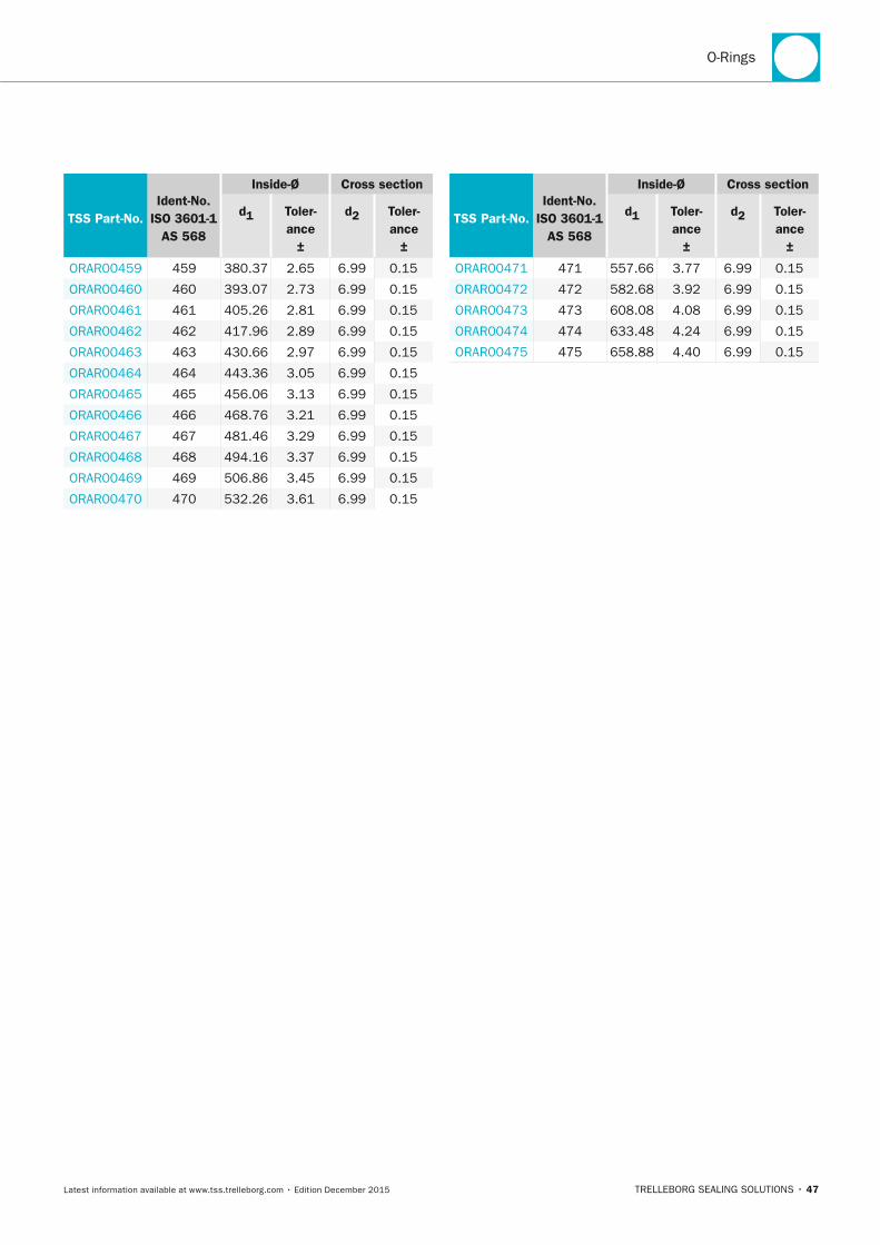
O-Rings
TRELLEBORG SEALING SOLUTIONS • 47Latest information available at www.tss.trelleborg.com • Edition December 2015
TSS Part-no.Ident-no.
ISO 3601-1 AS 568
Inside-Ø Cross section
d1 Toler-ance
±
d2 Toler-ance
±
ORAR00459 459 380.37 2.65 6.99 0.15
ORAR00460 460 393.07 2.73 6.99 0.15
ORAR00461 461 405.26 2.81 6.99 0.15
ORAR00462 462 417.96 2.89 6.99 0.15
ORAR00463 463 430.66 2.97 6.99 0.15
ORAR00464 464 443.36 3.05 6.99 0.15
ORAR00465 465 456.06 3.13 6.99 0.15
ORAR00466 466 468.76 3.21 6.99 0.15
ORAR00467 467 481.46 3.29 6.99 0.15
ORAR00468 468 494.16 3.37 6.99 0.15
ORAR00469 469 506.86 3.45 6.99 0.15
ORAR00470 470 532.26 3.61 6.99 0.15
TSS Part-no.Ident-no.
ISO 3601-1 AS 568
Inside-Ø Cross section
d1 Toler-ance
±
d2 Toler-ance
±
ORAR00471 471 557.66 3.77 6.99 0.15
ORAR00472 472 582.68 3.92 6.99 0.15
ORAR00473 473 608.08 4.08 6.99 0.15
ORAR00474 474 633.48 4.24 6.99 0.15
ORAR00475 475 658.88 4.40 6.99 0.15
FBP_neues_Layout_2015.indb 47 17.10.2016 13:35:20
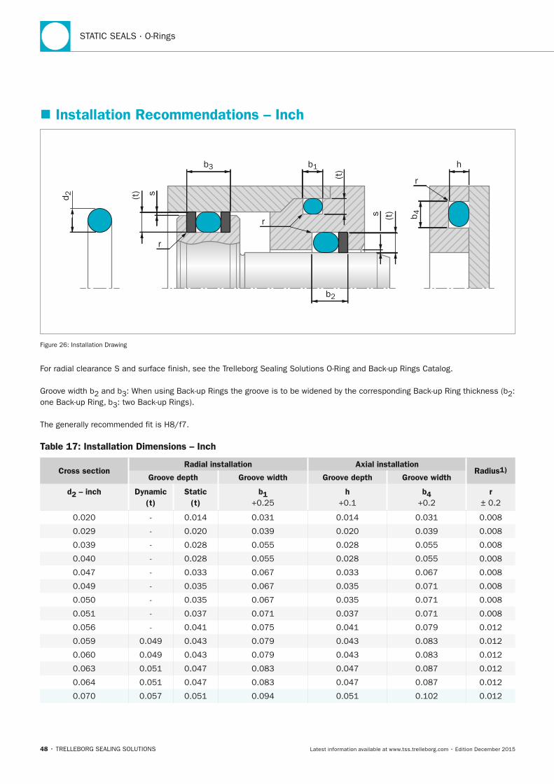
STATIC SEALS · O-Rings
48 • TRELLEBORG SEALING SOLUTIONS Latest information available at www.tss.trelleborg.com • Edition December 2015
� Installation Recommendations – Inch
b3 b1 h
b2
d 2
b 4
(t)
(t)s
r
r
r
(t) s
Figure 26: Installation Drawing
For radial clearance S and surface finish, see the Trelleborg Sealing Solutions O-Ring and Back-up Rings Catalog.
Groove width b2 and b3: When using Back-up Rings the groove is to be widened by the corresponding Back-up Ring thickness (b2: one Back-up Ring, b3: two Back-up Rings).
The generally recommended fit is H8/f7.
Table 17: Installation Dimensions – Inch
Cross sectionRadial installation Axial installation
Radius1)Groove depth Groove width Groove depth Groove width
d2 – inch Dynamic (t)
Static (t)
b1 +0.25
h +0.1
b4 +0.2
r ± 0.2
0.020 - 0.014 0.031 0.014 0.031 0.008
0.029 - 0.020 0.039 0.020 0.039 0.008
0.039 - 0.028 0.055 0.028 0.055 0.008
0.040 - 0.028 0.055 0.028 0.055 0.008
0.047 - 0.033 0.067 0.033 0.067 0.008
0.049 - 0.035 0.067 0.035 0.071 0.008
0.050 - 0.035 0.067 0.035 0.071 0.008
0.051 - 0.037 0.071 0.037 0.071 0.008
0.056 - 0.041 0.075 0.041 0.079 0.012
0.059 0.049 0.043 0.079 0.043 0.083 0.012
0.060 0.049 0.043 0.079 0.043 0.083 0.012
0.063 0.051 0.047 0.083 0.047 0.087 0.012
0.064 0.051 0.047 0.083 0.047 0.087 0.012
0.070 0.057 0.051 0.094 0.051 0.102 0.012
FBP_neues_Layout_2015.indb 48 17.10.2016 13:35:20
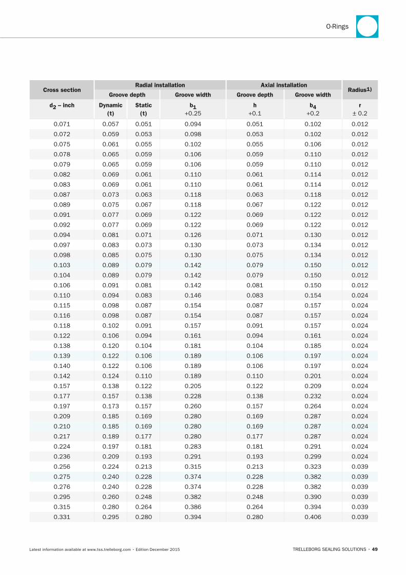
O-Rings
TRELLEBORG SEALING SOLUTIONS • 49Latest information available at www.tss.trelleborg.com • Edition December 2015
Cross sectionRadial installation Axial installation
Radius1)Groove depth Groove width Groove depth Groove width
d2 – inch Dynamic (t)
Static (t)
b1 +0.25
h +0.1
b4 +0.2
r ± 0.2
0.071 0.057 0.051 0.094 0.051 0.102 0.012
0.072 0.059 0.053 0.098 0.053 0.102 0.012
0.075 0.061 0.055 0.102 0.055 0.106 0.012
0.078 0.065 0.059 0.106 0.059 0.110 0.012
0.079 0.065 0.059 0.106 0.059 0.110 0.012
0.082 0.069 0.061 0.110 0.061 0.114 0.012
0.083 0.069 0.061 0.110 0.061 0.114 0.012
0.087 0.073 0.063 0.118 0.063 0.118 0.012
0.089 0.075 0.067 0.118 0.067 0.122 0.012
0.091 0.077 0.069 0.122 0.069 0.122 0.012
0.092 0.077 0.069 0.122 0.069 0.122 0.012
0.094 0.081 0.071 0.126 0.071 0.130 0.012
0.097 0.083 0.073 0.130 0.073 0.134 0.012
0.098 0.085 0.075 0.130 0.075 0.134 0.012
0.103 0.089 0.079 0.142 0.079 0.150 0.012
0.104 0.089 0.079 0.142 0.079 0.150 0.012
0.106 0.091 0.081 0.142 0.081 0.150 0.012
0.110 0.094 0.083 0.146 0.083 0.154 0.024
0.115 0.098 0.087 0.154 0.087 0.157 0.024
0.116 0.098 0.087 0.154 0.087 0.157 0.024
0.118 0.102 0.091 0.157 0.091 0.157 0.024
0.122 0.106 0.094 0.161 0.094 0.161 0.024
0.138 0.120 0.104 0.181 0.104 0.185 0.024
0.139 0.122 0.106 0.189 0.106 0.197 0.024
0.140 0.122 0.106 0.189 0.106 0.197 0.024
0.142 0.124 0.110 0.189 0.110 0.201 0.024
0.157 0.138 0.122 0.205 0.122 0.209 0.024
0.177 0.157 0.138 0.228 0.138 0.232 0.024
0.197 0.173 0.157 0.260 0.157 0.264 0.024
0.209 0.185 0.169 0.280 0.169 0.287 0.024
0.210 0.185 0.169 0.280 0.169 0.287 0.024
0.217 0.189 0.177 0.280 0.177 0.287 0.024
0.224 0.197 0.181 0.283 0.181 0.291 0.024
0.236 0.209 0.193 0.291 0.193 0.299 0.024
0.256 0.224 0.213 0.315 0.213 0.323 0.039
0.275 0.240 0.228 0.374 0.228 0.382 0.039
0.276 0.240 0.228 0.374 0.228 0.382 0.039
0.295 0.260 0.248 0.382 0.248 0.390 0.039
0.315 0.280 0.264 0.386 0.264 0.394 0.039
0.331 0.295 0.280 0.394 0.280 0.406 0.039
FBP_neues_Layout_2015.indb 49 17.10.2016 13:35:21
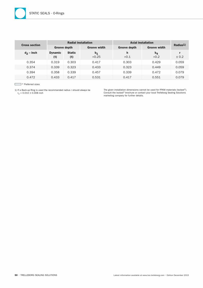
STATIC SEALS · O-Rings
50 • TRELLEBORG SEALING SOLUTIONS Latest information available at www.tss.trelleborg.com • Edition December 2015
Cross sectionRadial installation Axial installation
Radius1)Groove depth Groove width Groove depth Groove width
d2 – inch Dynamic (t)
Static (t)
b1 +0.25
h +0.1
b4 +0.2
r ± 0.2
0.354 0.319 0.303 0.417 0.303 0.429 0.059
0.374 0.339 0.323 0.433 0.323 0.449 0.059
0.394 0.358 0.339 0.457 0.339 0.472 0.079
0.472 0.433 0.417 0.531 0.417 0.551 0.079
* Preferred sizes
1) If a Back-up Ring is used the recommended radius r should always be r1 = 0.010 ± 0.008 inch
The given installation dimensions cannot be used for FFKM materials (Isolast®). Consult the Isolast® brochure or contact your local Trelleborg Sealing Solutions marketing company for further details.
FBP_neues_Layout_2015.indb 50 17.10.2016 13:35:21
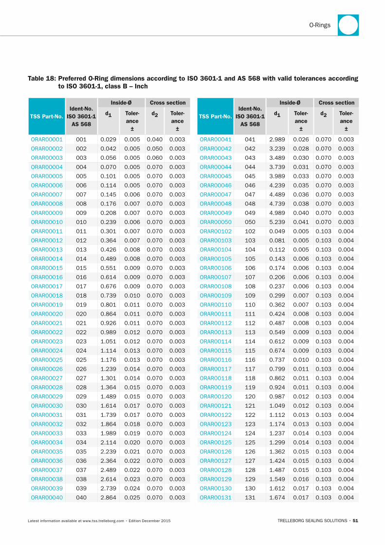
O-Rings
TRELLEBORG SEALING SOLUTIONS • 51Latest information available at www.tss.trelleborg.com • Edition December 2015
Table 18: Preferred O-Ring dimensions according to ISO 3601-1 and AS 568 with valid tolerances according to ISO 3601-1, class B – Inch
TSS Part-no.Ident-no.
ISO 3601-1 AS 568
Inside-Ø Cross section
d1 Toler-ance
±
d2 Toler-ance
±
ORAR00001 001 0.029 0.005 0.040 0.003
ORAR00002 002 0.042 0.005 0.050 0.003
ORAR00003 003 0.056 0.005 0.060 0.003
ORAR00004 004 0.070 0.005 0.070 0.003
ORAR00005 005 0.101 0.005 0.070 0.003
ORAR00006 006 0.114 0.005 0.070 0.003
ORAR00007 007 0.145 0.006 0.070 0.003
ORAR00008 008 0.176 0.007 0.070 0.003
ORAR00009 009 0.208 0.007 0.070 0.003
ORAR00010 010 0.239 0.006 0.070 0.003
ORAR00011 011 0.301 0.007 0.070 0.003
ORAR00012 012 0.364 0.007 0.070 0.003
ORAR00013 013 0.426 0.008 0.070 0.003
ORAR00014 014 0.489 0.008 0.070 0.003
ORAR00015 015 0.551 0.009 0.070 0.003
ORAR00016 016 0.614 0.009 0.070 0.003
ORAR00017 017 0.676 0.009 0.070 0.003
ORAR00018 018 0.739 0.010 0.070 0.003
ORAR00019 019 0.801 0.011 0.070 0.003
ORAR00020 020 0.864 0.011 0.070 0.003
ORAR00021 021 0.926 0.011 0.070 0.003
ORAR00022 022 0.989 0.012 0.070 0.003
ORAR00023 023 1.051 0.012 0.070 0.003
ORAR00024 024 1.114 0.013 0.070 0.003
ORAR00025 025 1.176 0.013 0.070 0.003
ORAR00026 026 1.239 0.014 0.070 0.003
ORAR00027 027 1.301 0.014 0.070 0.003
ORAR00028 028 1.364 0.015 0.070 0.003
ORAR00029 029 1.489 0.015 0.070 0.003
ORAR00030 030 1.614 0.017 0.070 0.003
ORAR00031 031 1.739 0.017 0.070 0.003
ORAR00032 032 1.864 0.018 0.070 0.003
ORAR00033 033 1.989 0.019 0.070 0.003
ORAR00034 034 2.114 0.020 0.070 0.003
ORAR00035 035 2.239 0.021 0.070 0.003
ORAR00036 036 2.364 0.022 0.070 0.003
ORAR00037 037 2.489 0.022 0.070 0.003
ORAR00038 038 2.614 0.023 0.070 0.003
ORAR00039 039 2.739 0.024 0.070 0.003
ORAR00040 040 2.864 0.025 0.070 0.003
TSS Part-no.Ident-no.
ISO 3601-1 AS 568
Inside-Ø Cross section
d1 Toler-ance
±
d2 Toler-ance
±
ORAR00041 041 2.989 0.026 0.070 0.003
ORAR00042 042 3.239 0.028 0.070 0.003
ORAR00043 043 3.489 0.030 0.070 0.003
ORAR00044 044 3.739 0.031 0.070 0.003
ORAR00045 045 3.989 0.033 0.070 0.003
ORAR00046 046 4.239 0.035 0.070 0.003
ORAR00047 047 4.489 0.036 0.070 0.003
ORAR00048 048 4.739 0.038 0.070 0.003
ORAR00049 049 4.989 0.040 0.070 0.003
ORAR00050 050 5.239 0.041 0.070 0.003
ORAR00102 102 0.049 0.005 0.103 0.004
ORAR00103 103 0.081 0.005 0.103 0.004
ORAR00104 104 0.112 0.005 0.103 0.004
ORAR00105 105 0.143 0.006 0.103 0.004
ORAR00106 106 0.174 0.006 0.103 0.004
ORAR00107 107 0.206 0.006 0.103 0.004
ORAR00108 108 0.237 0.006 0.103 0.004
ORAR00109 109 0.299 0.007 0.103 0.004
ORAR00110 110 0.362 0.007 0.103 0.004
ORAR00111 111 0.424 0.008 0.103 0.004
ORAR00112 112 0.487 0.008 0.103 0.004
ORAR00113 113 0.549 0.009 0.103 0.004
ORAR00114 114 0.612 0.009 0.103 0.004
ORAR00115 115 0.674 0.009 0.103 0.004
ORAR00116 116 0.737 0.010 0.103 0.004
ORAR00117 117 0.799 0.011 0.103 0.004
ORAR00118 118 0.862 0.011 0.103 0.004
ORAR00119 119 0.924 0.011 0.103 0.004
ORAR00120 120 0.987 0.012 0.103 0.004
ORAR00121 121 1.049 0.012 0.103 0.004
ORAR00122 122 1.112 0.013 0.103 0.004
ORAR00123 123 1.174 0.013 0.103 0.004
ORAR00124 124 1.237 0.014 0.103 0.004
ORAR00125 125 1.299 0.014 0.103 0.004
ORAR00126 126 1.362 0.015 0.103 0.004
ORAR00127 127 1.424 0.015 0.103 0.004
ORAR00128 128 1.487 0.015 0.103 0.004
ORAR00129 129 1.549 0.016 0.103 0.004
ORAR00130 130 1.612 0.017 0.103 0.004
ORAR00131 131 1.674 0.017 0.103 0.004
FBP_neues_Layout_2015.indb 51 17.10.2016 13:35:21
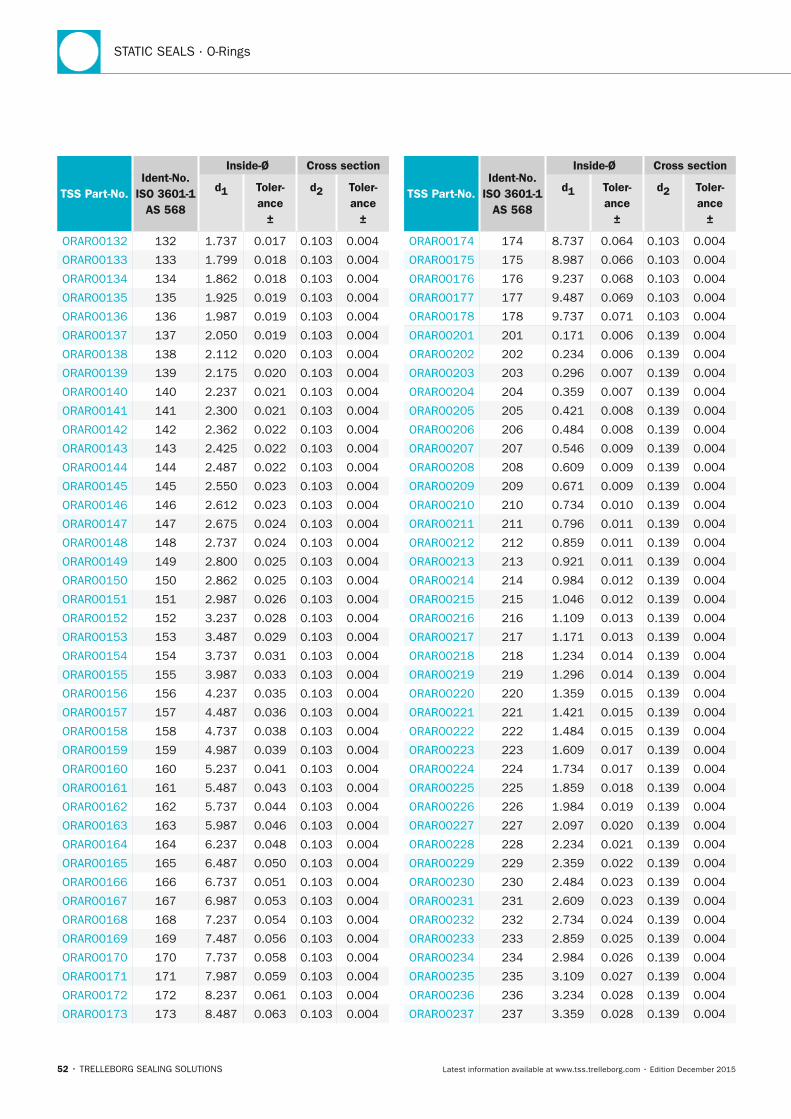
STATIC SEALS · O-Rings
52 • TRELLEBORG SEALING SOLUTIONS Latest information available at www.tss.trelleborg.com • Edition December 2015
TSS Part-no.Ident-no.
ISO 3601-1 AS 568
Inside-Ø Cross section
d1 Toler-ance
±
d2 Toler-ance
±
ORAR00132 132 1.737 0.017 0.103 0.004
ORAR00133 133 1.799 0.018 0.103 0.004
ORAR00134 134 1.862 0.018 0.103 0.004
ORAR00135 135 1.925 0.019 0.103 0.004
ORAR00136 136 1.987 0.019 0.103 0.004
ORAR00137 137 2.050 0.019 0.103 0.004
ORAR00138 138 2.112 0.020 0.103 0.004
ORAR00139 139 2.175 0.020 0.103 0.004
ORAR00140 140 2.237 0.021 0.103 0.004
ORAR00141 141 2.300 0.021 0.103 0.004
ORAR00142 142 2.362 0.022 0.103 0.004
ORAR00143 143 2.425 0.022 0.103 0.004
ORAR00144 144 2.487 0.022 0.103 0.004
ORAR00145 145 2.550 0.023 0.103 0.004
ORAR00146 146 2.612 0.023 0.103 0.004
ORAR00147 147 2.675 0.024 0.103 0.004
ORAR00148 148 2.737 0.024 0.103 0.004
ORAR00149 149 2.800 0.025 0.103 0.004
ORAR00150 150 2.862 0.025 0.103 0.004
ORAR00151 151 2.987 0.026 0.103 0.004
ORAR00152 152 3.237 0.028 0.103 0.004
ORAR00153 153 3.487 0.029 0.103 0.004
ORAR00154 154 3.737 0.031 0.103 0.004
ORAR00155 155 3.987 0.033 0.103 0.004
ORAR00156 156 4.237 0.035 0.103 0.004
ORAR00157 157 4.487 0.036 0.103 0.004
ORAR00158 158 4.737 0.038 0.103 0.004
ORAR00159 159 4.987 0.039 0.103 0.004
ORAR00160 160 5.237 0.041 0.103 0.004
ORAR00161 161 5.487 0.043 0.103 0.004
ORAR00162 162 5.737 0.044 0.103 0.004
ORAR00163 163 5.987 0.046 0.103 0.004
ORAR00164 164 6.237 0.048 0.103 0.004
ORAR00165 165 6.487 0.050 0.103 0.004
ORAR00166 166 6.737 0.051 0.103 0.004
ORAR00167 167 6.987 0.053 0.103 0.004
ORAR00168 168 7.237 0.054 0.103 0.004
ORAR00169 169 7.487 0.056 0.103 0.004
ORAR00170 170 7.737 0.058 0.103 0.004
ORAR00171 171 7.987 0.059 0.103 0.004
ORAR00172 172 8.237 0.061 0.103 0.004
ORAR00173 173 8.487 0.063 0.103 0.004
TSS Part-no.Ident-no.
ISO 3601-1 AS 568
Inside-Ø Cross section
d1 Toler-ance
±
d2 Toler-ance
±
ORAR00174 174 8.737 0.064 0.103 0.004
ORAR00175 175 8.987 0.066 0.103 0.004
ORAR00176 176 9.237 0.068 0.103 0.004
ORAR00177 177 9.487 0.069 0.103 0.004
ORAR00178 178 9.737 0.071 0.103 0.004
ORAR00201 201 0.171 0.006 0.139 0.004
ORAR00202 202 0.234 0.006 0.139 0.004
ORAR00203 203 0.296 0.007 0.139 0.004
ORAR00204 204 0.359 0.007 0.139 0.004
ORAR00205 205 0.421 0.008 0.139 0.004
ORAR00206 206 0.484 0.008 0.139 0.004
ORAR00207 207 0.546 0.009 0.139 0.004
ORAR00208 208 0.609 0.009 0.139 0.004
ORAR00209 209 0.671 0.009 0.139 0.004
ORAR00210 210 0.734 0.010 0.139 0.004
ORAR00211 211 0.796 0.011 0.139 0.004
ORAR00212 212 0.859 0.011 0.139 0.004
ORAR00213 213 0.921 0.011 0.139 0.004
ORAR00214 214 0.984 0.012 0.139 0.004
ORAR00215 215 1.046 0.012 0.139 0.004
ORAR00216 216 1.109 0.013 0.139 0.004
ORAR00217 217 1.171 0.013 0.139 0.004
ORAR00218 218 1.234 0.014 0.139 0.004
ORAR00219 219 1.296 0.014 0.139 0.004
ORAR00220 220 1.359 0.015 0.139 0.004
ORAR00221 221 1.421 0.015 0.139 0.004
ORAR00222 222 1.484 0.015 0.139 0.004
ORAR00223 223 1.609 0.017 0.139 0.004
ORAR00224 224 1.734 0.017 0.139 0.004
ORAR00225 225 1.859 0.018 0.139 0.004
ORAR00226 226 1.984 0.019 0.139 0.004
ORAR00227 227 2.097 0.020 0.139 0.004
ORAR00228 228 2.234 0.021 0.139 0.004
ORAR00229 229 2.359 0.022 0.139 0.004
ORAR00230 230 2.484 0.023 0.139 0.004
ORAR00231 231 2.609 0.023 0.139 0.004
ORAR00232 232 2.734 0.024 0.139 0.004
ORAR00233 233 2.859 0.025 0.139 0.004
ORAR00234 234 2.984 0.026 0.139 0.004
ORAR00235 235 3.109 0.027 0.139 0.004
ORAR00236 236 3.234 0.028 0.139 0.004
ORAR00237 237 3.359 0.028 0.139 0.004
FBP_neues_Layout_2015.indb 52 17.10.2016 13:35:22
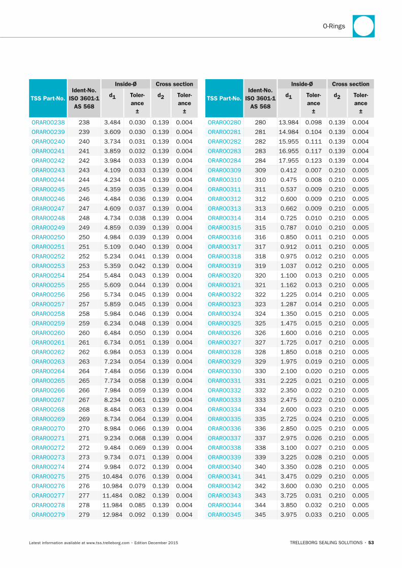
O-Rings
TRELLEBORG SEALING SOLUTIONS • 53Latest information available at www.tss.trelleborg.com • Edition December 2015
TSS Part-no.Ident-no.
ISO 3601-1 AS 568
Inside-Ø Cross section
d1 Toler-ance
±
d2 Toler-ance
±
ORAR00238 238 3.484 0.030 0.139 0.004
ORAR00239 239 3.609 0.030 0.139 0.004
ORAR00240 240 3.734 0.031 0.139 0.004
ORAR00241 241 3.859 0.032 0.139 0.004
ORAR00242 242 3.984 0.033 0.139 0.004
ORAR00243 243 4.109 0.033 0.139 0.004
ORAR00244 244 4.234 0.034 0.139 0.004
ORAR00245 245 4.359 0.035 0.139 0.004
ORAR00246 246 4.484 0.036 0.139 0.004
ORAR00247 247 4.609 0.037 0.139 0.004
ORAR00248 248 4.734 0.038 0.139 0.004
ORAR00249 249 4.859 0.039 0.139 0.004
ORAR00250 250 4.984 0.039 0.139 0.004
ORAR00251 251 5.109 0.040 0.139 0.004
ORAR00252 252 5.234 0.041 0.139 0.004
ORAR00253 253 5.359 0.042 0.139 0.004
ORAR00254 254 5.484 0.043 0.139 0.004
ORAR00255 255 5.609 0.044 0.139 0.004
ORAR00256 256 5.734 0.045 0.139 0.004
ORAR00257 257 5.859 0.045 0.139 0.004
ORAR00258 258 5.984 0.046 0.139 0.004
ORAR00259 259 6.234 0.048 0.139 0.004
ORAR00260 260 6.484 0.050 0.139 0.004
ORAR00261 261 6.734 0.051 0.139 0.004
ORAR00262 262 6.984 0.053 0.139 0.004
ORAR00263 263 7.234 0.054 0.139 0.004
ORAR00264 264 7.484 0.056 0.139 0.004
ORAR00265 265 7.734 0.058 0.139 0.004
ORAR00266 266 7.984 0.059 0.139 0.004
ORAR00267 267 8.234 0.061 0.139 0.004
ORAR00268 268 8.484 0.063 0.139 0.004
ORAR00269 269 8.734 0.064 0.139 0.004
ORAR00270 270 8.984 0.066 0.139 0.004
ORAR00271 271 9.234 0.068 0.139 0.004
ORAR00272 272 9.484 0.069 0.139 0.004
ORAR00273 273 9.734 0.071 0.139 0.004
ORAR00274 274 9.984 0.072 0.139 0.004
ORAR00275 275 10.484 0.076 0.139 0.004
ORAR00276 276 10.984 0.079 0.139 0.004
ORAR00277 277 11.484 0.082 0.139 0.004
ORAR00278 278 11.984 0.085 0.139 0.004
ORAR00279 279 12.984 0.092 0.139 0.004
TSS Part-no.Ident-no.
ISO 3601-1 AS 568
Inside-Ø Cross section
d1 Toler-ance
±
d2 Toler-ance
±
ORAR00280 280 13.984 0.098 0.139 0.004
ORAR00281 281 14.984 0.104 0.139 0.004
ORAR00282 282 15.955 0.111 0.139 0.004
ORAR00283 283 16.955 0.117 0.139 0.004
ORAR00284 284 17.955 0.123 0.139 0.004
ORAR00309 309 0.412 0.007 0.210 0.005
ORAR00310 310 0.475 0.008 0.210 0.005
ORAR00311 311 0.537 0.009 0.210 0.005
ORAR00312 312 0.600 0.009 0.210 0.005
ORAR00313 313 0.662 0.009 0.210 0.005
ORAR00314 314 0.725 0.010 0.210 0.005
ORAR00315 315 0.787 0.010 0.210 0.005
ORAR00316 316 0.850 0.011 0.210 0.005
ORAR00317 317 0.912 0.011 0.210 0.005
ORAR00318 318 0.975 0.012 0.210 0.005
ORAR00319 319 1.037 0.012 0.210 0.005
ORAR00320 320 1.100 0.013 0.210 0.005
ORAR00321 321 1.162 0.013 0.210 0.005
ORAR00322 322 1.225 0.014 0.210 0.005
ORAR00323 323 1.287 0.014 0.210 0.005
ORAR00324 324 1.350 0.015 0.210 0.005
ORAR00325 325 1.475 0.015 0.210 0.005
ORAR00326 326 1.600 0.016 0.210 0.005
ORAR00327 327 1.725 0.017 0.210 0.005
ORAR00328 328 1.850 0.018 0.210 0.005
ORAR00329 329 1.975 0.019 0.210 0.005
ORAR00330 330 2.100 0.020 0.210 0.005
ORAR00331 331 2.225 0.021 0.210 0.005
ORAR00332 332 2.350 0.022 0.210 0.005
ORAR00333 333 2.475 0.022 0.210 0.005
ORAR00334 334 2.600 0.023 0.210 0.005
ORAR00335 335 2.725 0.024 0.210 0.005
ORAR00336 336 2.850 0.025 0.210 0.005
ORAR00337 337 2.975 0.026 0.210 0.005
ORAR00338 338 3.100 0.027 0.210 0.005
ORAR00339 339 3.225 0.028 0.210 0.005
ORAR00340 340 3.350 0.028 0.210 0.005
ORAR00341 341 3.475 0.029 0.210 0.005
ORAR00342 342 3.600 0.030 0.210 0.005
ORAR00343 343 3.725 0.031 0.210 0.005
ORAR00344 344 3.850 0.032 0.210 0.005
ORAR00345 345 3.975 0.033 0.210 0.005
FBP_neues_Layout_2015.indb 53 17.10.2016 13:35:23
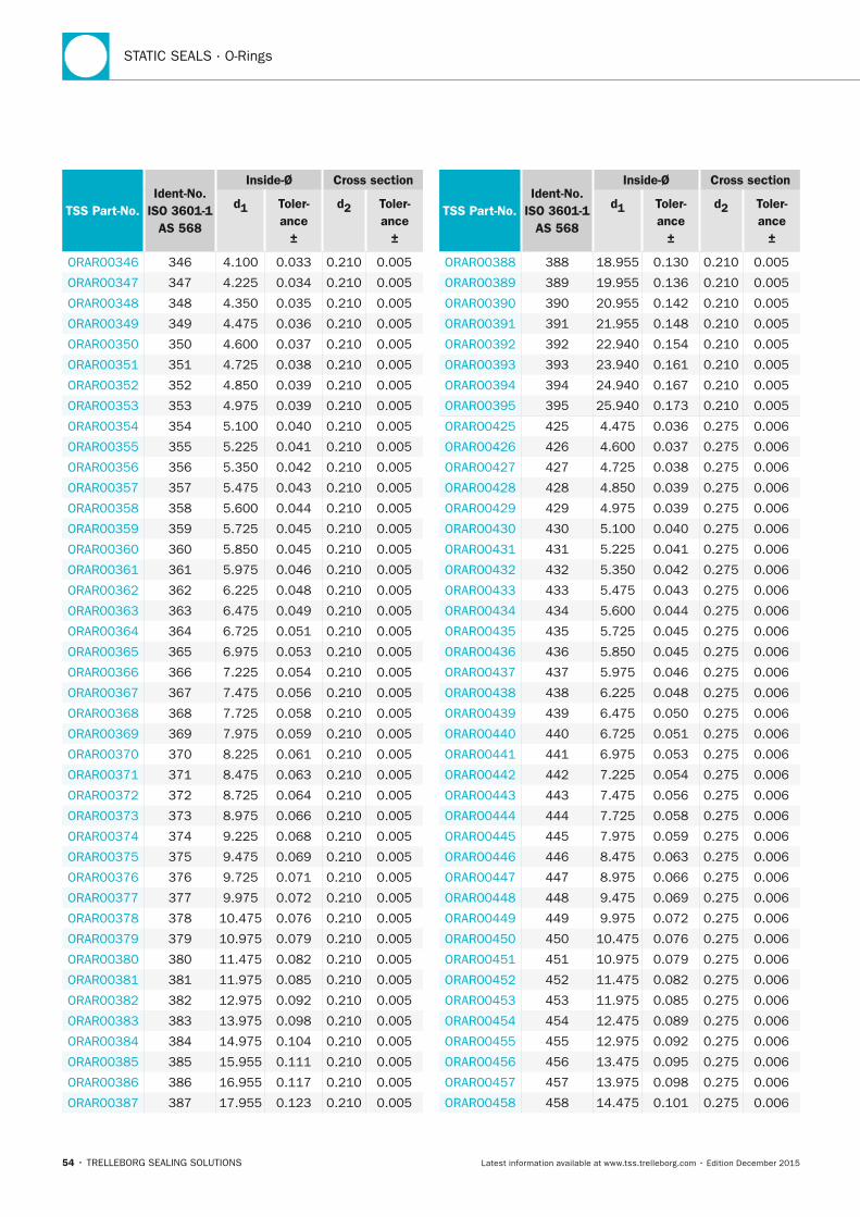
STATIC SEALS · O-Rings
54 • TRELLEBORG SEALING SOLUTIONS Latest information available at www.tss.trelleborg.com • Edition December 2015
TSS Part-no.Ident-no.
ISO 3601-1 AS 568
Inside-Ø Cross section
d1 Toler-ance
±
d2 Toler-ance
±
ORAR00346 346 4.100 0.033 0.210 0.005
ORAR00347 347 4.225 0.034 0.210 0.005
ORAR00348 348 4.350 0.035 0.210 0.005
ORAR00349 349 4.475 0.036 0.210 0.005
ORAR00350 350 4.600 0.037 0.210 0.005
ORAR00351 351 4.725 0.038 0.210 0.005
ORAR00352 352 4.850 0.039 0.210 0.005
ORAR00353 353 4.975 0.039 0.210 0.005
ORAR00354 354 5.100 0.040 0.210 0.005
ORAR00355 355 5.225 0.041 0.210 0.005
ORAR00356 356 5.350 0.042 0.210 0.005
ORAR00357 357 5.475 0.043 0.210 0.005
ORAR00358 358 5.600 0.044 0.210 0.005
ORAR00359 359 5.725 0.045 0.210 0.005
ORAR00360 360 5.850 0.045 0.210 0.005
ORAR00361 361 5.975 0.046 0.210 0.005
ORAR00362 362 6.225 0.048 0.210 0.005
ORAR00363 363 6.475 0.049 0.210 0.005
ORAR00364 364 6.725 0.051 0.210 0.005
ORAR00365 365 6.975 0.053 0.210 0.005
ORAR00366 366 7.225 0.054 0.210 0.005
ORAR00367 367 7.475 0.056 0.210 0.005
ORAR00368 368 7.725 0.058 0.210 0.005
ORAR00369 369 7.975 0.059 0.210 0.005
ORAR00370 370 8.225 0.061 0.210 0.005
ORAR00371 371 8.475 0.063 0.210 0.005
ORAR00372 372 8.725 0.064 0.210 0.005
ORAR00373 373 8.975 0.066 0.210 0.005
ORAR00374 374 9.225 0.068 0.210 0.005
ORAR00375 375 9.475 0.069 0.210 0.005
ORAR00376 376 9.725 0.071 0.210 0.005
ORAR00377 377 9.975 0.072 0.210 0.005
ORAR00378 378 10.475 0.076 0.210 0.005
ORAR00379 379 10.975 0.079 0.210 0.005
ORAR00380 380 11.475 0.082 0.210 0.005
ORAR00381 381 11.975 0.085 0.210 0.005
ORAR00382 382 12.975 0.092 0.210 0.005
ORAR00383 383 13.975 0.098 0.210 0.005
ORAR00384 384 14.975 0.104 0.210 0.005
ORAR00385 385 15.955 0.111 0.210 0.005
ORAR00386 386 16.955 0.117 0.210 0.005
ORAR00387 387 17.955 0.123 0.210 0.005
TSS Part-no.Ident-no.
ISO 3601-1 AS 568
Inside-Ø Cross section
d1 Toler-ance
±
d2 Toler-ance
±
ORAR00388 388 18.955 0.130 0.210 0.005
ORAR00389 389 19.955 0.136 0.210 0.005
ORAR00390 390 20.955 0.142 0.210 0.005
ORAR00391 391 21.955 0.148 0.210 0.005
ORAR00392 392 22.940 0.154 0.210 0.005
ORAR00393 393 23.940 0.161 0.210 0.005
ORAR00394 394 24.940 0.167 0.210 0.005
ORAR00395 395 25.940 0.173 0.210 0.005
ORAR00425 425 4.475 0.036 0.275 0.006
ORAR00426 426 4.600 0.037 0.275 0.006
ORAR00427 427 4.725 0.038 0.275 0.006
ORAR00428 428 4.850 0.039 0.275 0.006
ORAR00429 429 4.975 0.039 0.275 0.006
ORAR00430 430 5.100 0.040 0.275 0.006
ORAR00431 431 5.225 0.041 0.275 0.006
ORAR00432 432 5.350 0.042 0.275 0.006
ORAR00433 433 5.475 0.043 0.275 0.006
ORAR00434 434 5.600 0.044 0.275 0.006
ORAR00435 435 5.725 0.045 0.275 0.006
ORAR00436 436 5.850 0.045 0.275 0.006
ORAR00437 437 5.975 0.046 0.275 0.006
ORAR00438 438 6.225 0.048 0.275 0.006
ORAR00439 439 6.475 0.050 0.275 0.006
ORAR00440 440 6.725 0.051 0.275 0.006
ORAR00441 441 6.975 0.053 0.275 0.006
ORAR00442 442 7.225 0.054 0.275 0.006
ORAR00443 443 7.475 0.056 0.275 0.006
ORAR00444 444 7.725 0.058 0.275 0.006
ORAR00445 445 7.975 0.059 0.275 0.006
ORAR00446 446 8.475 0.063 0.275 0.006
ORAR00447 447 8.975 0.066 0.275 0.006
ORAR00448 448 9.475 0.069 0.275 0.006
ORAR00449 449 9.975 0.072 0.275 0.006
ORAR00450 450 10.475 0.076 0.275 0.006
ORAR00451 451 10.975 0.079 0.275 0.006
ORAR00452 452 11.475 0.082 0.275 0.006
ORAR00453 453 11.975 0.085 0.275 0.006
ORAR00454 454 12.475 0.089 0.275 0.006
ORAR00455 455 12.975 0.092 0.275 0.006
ORAR00456 456 13.475 0.095 0.275 0.006
ORAR00457 457 13.975 0.098 0.275 0.006
ORAR00458 458 14.475 0.101 0.275 0.006
FBP_neues_Layout_2015.indb 54 17.10.2016 13:35:24
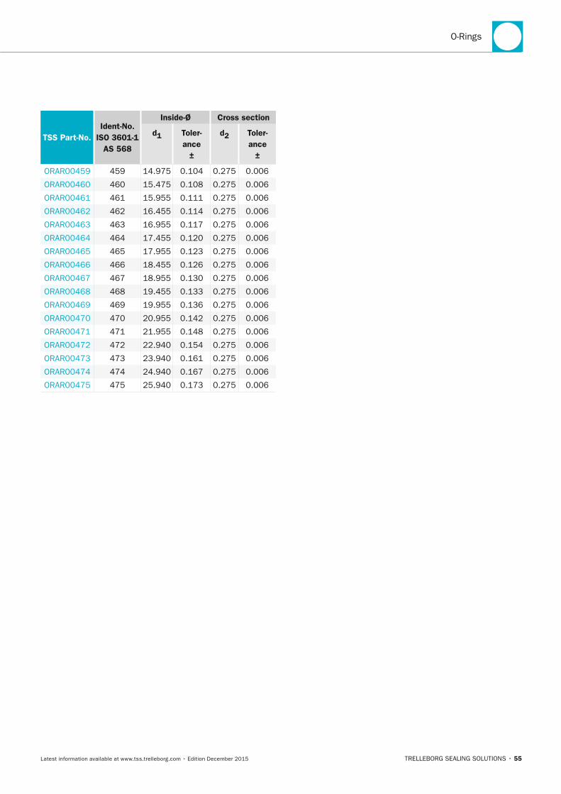
O-Rings
TRELLEBORG SEALING SOLUTIONS • 55Latest information available at www.tss.trelleborg.com • Edition December 2015
TSS Part-no.Ident-no.
ISO 3601-1 AS 568
Inside-Ø Cross section
d1 Toler-ance
±
d2 Toler-ance
±
ORAR00459 459 14.975 0.104 0.275 0.006
ORAR00460 460 15.475 0.108 0.275 0.006
ORAR00461 461 15.955 0.111 0.275 0.006
ORAR00462 462 16.455 0.114 0.275 0.006
ORAR00463 463 16.955 0.117 0.275 0.006
ORAR00464 464 17.455 0.120 0.275 0.006
ORAR00465 465 17.955 0.123 0.275 0.006
ORAR00466 466 18.455 0.126 0.275 0.006
ORAR00467 467 18.955 0.130 0.275 0.006
ORAR00468 468 19.455 0.133 0.275 0.006
ORAR00469 469 19.955 0.136 0.275 0.006
ORAR00470 470 20.955 0.142 0.275 0.006
ORAR00471 471 21.955 0.148 0.275 0.006
ORAR00472 472 22.940 0.154 0.275 0.006
ORAR00473 473 23.940 0.161 0.275 0.006
ORAR00474 474 24.940 0.167 0.275 0.006
ORAR00475 475 25.940 0.173 0.275 0.006
FBP_neues_Layout_2015.indb 55 17.10.2016 13:35:24

STATIC SEALS · O-Rings
56 • TRELLEBORG SEALING SOLUTIONS Latest information available at www.tss.trelleborg.com • Edition December 2015
FBP_neues_Layout_2015.indb 56 17.10.2016 13:35:24
STATIC SEALS
TRELLEBORG SEALING SOLUTIONS • 57Latest information available at www.tss.trelleborg.com • Edition December 2015
SpecialO-RingsSpecialO-RingsSpecialVery good chemical resistance to most liquids and chemicals
Physiologically safe and can be sterilized
Low friction, no adhesion or stick-slip effect
Low leach-out levels
FBP_neues_Layout_2015.indb 57 17.10.2016 13:35:29

STATIC SEALS · Special O-Rings
58 • TRELLEBORG SEALING SOLUTIONS Latest information available at www.tss.trelleborg.com • Edition December 2015
FBP_neues_Layout_2015.indb 58 17.10.2016 13:35:29
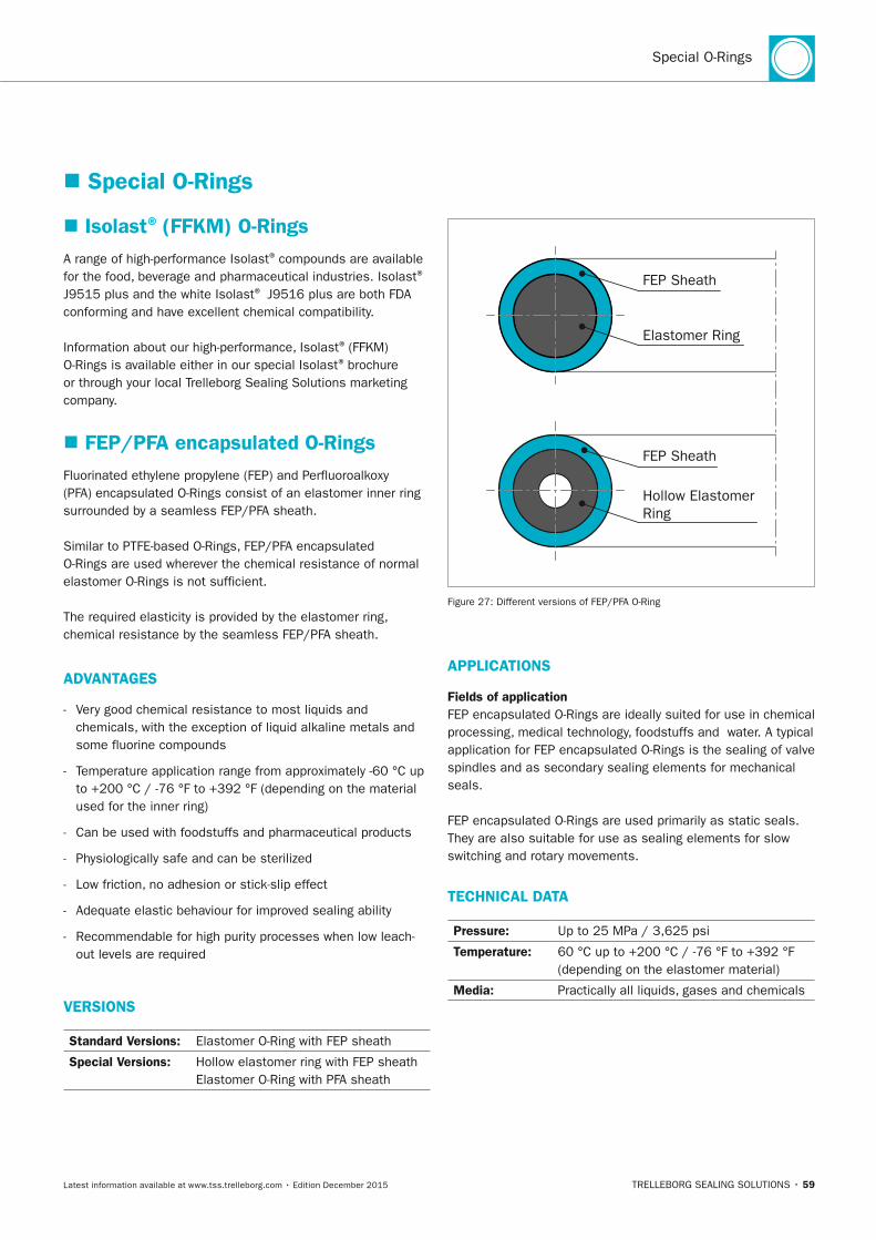
Special O-Rings
TRELLEBORG SEALING SOLUTIONS • 59Latest information available at www.tss.trelleborg.com • Edition December 2015
� Special O-Rings
� Isolast® (FFKM) O-RingsA range of high-performance Isolast® compounds are available for the food, beverage and pharmaceutical industries. Isolast®
J9515 plus and the white Isolast® J9516 plus are both FDA conforming and have excellent chemical compatibility.
Information about our high-performance, Isolast® (FFKM) O-Rings is available either in our special Isolast® brochure or through your local Trelleborg Sealing Solutions marketing company.
� FEP/PFA encapsulated O-RingsFluorinated ethylene propylene (FEP) and Perfluoroalkoxy (PFA) encapsulated O-Rings consist of an elastomer inner ring surrounded by a seamless FEP/PFA sheath.
Similar to PTFE-based O-Rings, FEP/PFA encapsulated O-Rings are used wherever the chemical resistance of normal elastomer O-Rings is not sufficient.
The required elasticity is provided by the elastomer ring, chemical resistance by the seamless FEP/PFA sheath.
ADVAnTAGES
- Very good chemical resistance to most liquids and chemicals, with the exception of liquid alkaline metals and some fluorine compounds
- Temperature application range from approximately -60 °C up to +200 °C / -76 °F to +392 °F (depending on the material used for the inner ring)
- Can be used with foodstuffs and pharmaceutical products
- Physiologically safe and can be sterilized
- Low friction, no adhesion or stick-slip effect
- Adequate elastic behaviour for improved sealing ability
- Recommendable for high purity processes when low leach- out levels are required
VERSIOnS
Standard Versions: Elastomer O-Ring with FEP sheath
Special Versions: Hollow elastomer ring with FEP sheath Elastomer O-Ring with PFA sheath
FEP Sheath
Elastomer Ring
FEP Sheath
Hollow Elastomer Ring
Figure 27: Different versions of FEP/PFA O-Ring
APPLICATIOnS
Fields of applicationFEP encapsulated O-Rings are ideally suited for use in chemical processing, medical technology, foodstuffs and water. A typical application for FEP encapsulated O-Rings is the sealing of valve spindles and as secondary sealing elements for mechanical seals.
FEP encapsulated O-Rings are used primarily as static seals. They are also suitable for use as sealing elements for slow switching and rotary movements.
TECHnICAL DATA
Pressure: Up to 25 MPa / 3,625 psi
Temperature: 60 °C up to +200 °C / -76 °F to +392 °F (depending on the elastomer material)
Media: Practically all liquids, gases and chemicals
FBP_neues_Layout_2015.indb 59 17.10.2016 13:35:30
STATIC SEALS · Special O-Rings
60 • TRELLEBORG SEALING SOLUTIONS Latest information available at www.tss.trelleborg.com • Edition December 2015
MATERIALS
FEP sheathFEP is the abbreviated designation for Tetrafluoroethylene-hexafluoropropylene. This material has similar properties to those of Polytetrafluoroethylene (PTFE). It also has a very high chemical resistance and exhibits a good resistance to abrasion.
In contrast to PTFE, however, FEP is thermoplastically moldable. This allows the material to be processed to form flexible semifinished products, such as thin-walled hoses.
PFA sheathPFA is the abbreviation for Perfluoroalkoxy alkane. This material is a type of Fluoropolymer with properties similar to Polytetrafluoroethylene (PTFE). Differing from PTFE, like FEP, PFA it is melt-processable but shares PTFE's useful properties of a low coefficient of friction and non-reactivity.
PFA is preferable to FEP in high temperature situations. PFA is more affected by water absorption and weathering than FEP, but is superior in terms of salt spray resistance.
Inner ringA choice of three materials is available for the elastomer inner rings with FEP encapsulation and two materials for the inner ring with PFA encapsulation. The choice of the material also determines the service temperature range.
- Fluorocarbon Rubber (FKM) Temperature range: -20 °C up to +200 °C / -4 °F to +392 °F
- Silicone Rubber (VMQ) Temperature range: -50 °C up to +175 °C / -58 °F to +347 °F
- Ethylene Propylene Diene Rubber Temperature range: -45 °C up to +150 °C / -49 °F to +302 °F
The specified temperature ranges are limits which must always be considered in conjunction with the media to be sealed and the working pressure. The permissible continuous operating temperatures are always lower than the given upper limits.
DESIGn RECOMMEnDATIOnS
FEP encapsulated O-Rings are fully interchangeable with standard O-Ring seals. There is no need to modify the groove dimensions as the FEP sheath is relatively thin-walled.
All the specifications given in this section therefore refer to the installation dimensions of elastomer O-Rings.
As a result of the FEP sheath, the O-Rings are less flexible than elastomer O-Rings. They have limited stretch and higher permanent deformation.
Split-grooves are recommended, especially for outside sealing FEP encapsulated O-Rings, in order to avoid overstretching during installation.
The general information on the construction, design and surfaces given for elastomer O-Rings also apply to FEP encapsulated O-Rings.
At higher pressures, additional concave Back-up Rings should be used.
Application in gasesWhere the encapsulated O-Ring is used to seal gases, the permeation rate must be taken into consideration. In this case, the material of the inner ring must also have a good resistance to the media to be sealed. The permeation rate depends on the exposed surface area, the temperature, the working pressure and the thickness of the FEP sheath.
The thickness of the FEP sheath can be found in Table 19/20.
Compliances and approvalsFEP and PFA sheaths are in compliance with the following regulations governing plastic materials for food contact applications:
- FDA Regulation 21 CFR Part 177.1550
- NSF 61 requirements
- 3A Sanitary Standard Number 20-22
- USP Class VI, Chapter 88
- Regulation (EC) No. 1935/2004
- Regulation (EU) No. 10/2011
FBP_neues_Layout_2015.indb 60 17.10.2016 13:35:30
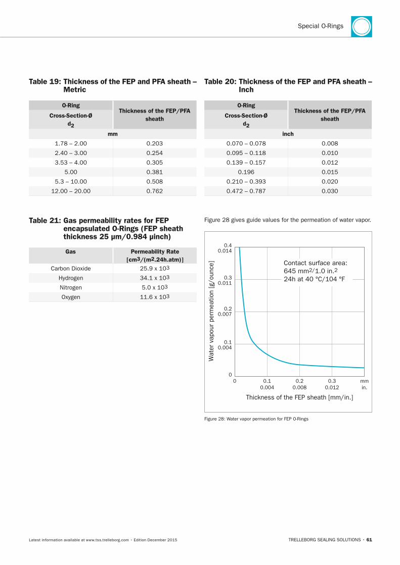
Special O-Rings
TRELLEBORG SEALING SOLUTIONS • 61Latest information available at www.tss.trelleborg.com • Edition December 2015
Table 19: Thickness of the FEP and PFA sheath – Metric
O-RingThickness of the FEP/PFA
sheathCross-Section-Ø d2
mm
1.78 – 2.00 0.203
2.40 – 3.00 0.254
3.53 – 4.00 0.305
5.00 0.381
5.3 – 10.00 0.508
12.00 – 20.00 0.762
Table 20: Thickness of the FEP and PFA sheath – Inch
O-RingThickness of the FEP/PFA
sheathCross-Section-Ø d2
inch
0.070 – 0.078 0.008
0.095 – 0.118 0.010
0.139 – 0.157 0.012
0.196 0.015
0.210 – 0.393 0.020
0.472 – 0.787 0.030
Table 21: Gas permeability rates for FEP encapsulated O-Rings (FEP sheath thickness 25 µm/0.984 µinch)
Gas Permeability Rate[cm3/(m2.24h.atm)]
Carbon Dioxide 25.9 x 10³
Hydrogen 34.1 x 10³
Nitrogen 5.0 x 10³
Oxygen 11.6 x 10³
Figure 28 gives guide values for the permeation of water vapor.
0.10.004
0 0.20.008
0.30.012
Wat
er v
apou
r pe
rmea
tion
[g/o
unce
]
Thickness of the FEP sheath [mm/in.]
0.10.004
0
0.20.007
0.30.011
0.40.014
mmin.
Contact surface area: 645 mm2/1.0 in.224h at 40 °C/104 °F
Figure 28: Water vapor permeation for FEP O-Rings
FBP_neues_Layout_2015.indb 61 17.10.2016 13:35:30
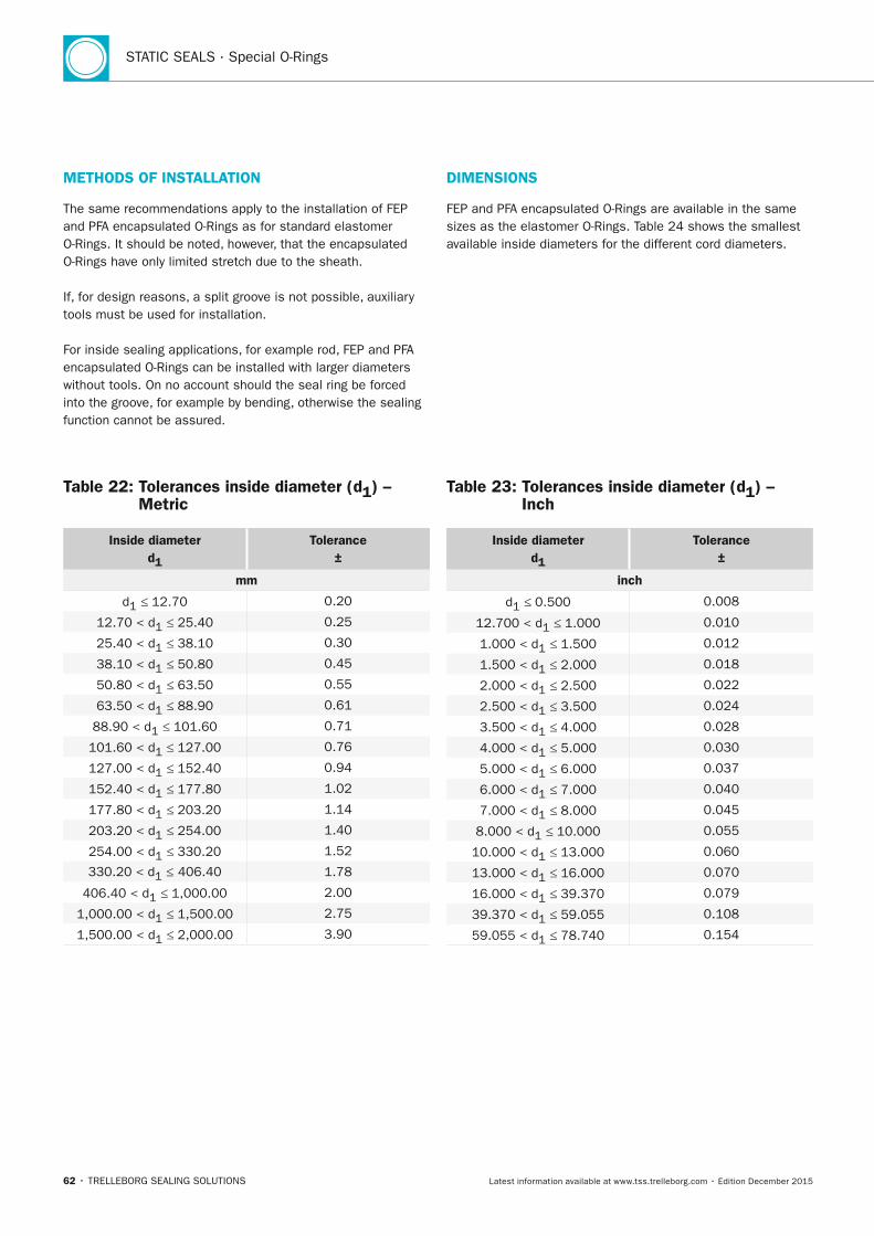
STATIC SEALS · Special O-Rings
62 • TRELLEBORG SEALING SOLUTIONS Latest information available at www.tss.trelleborg.com • Edition December 2015
METHODS OF InSTALLATIOn
The same recommendations apply to the installation of FEP and PFA encapsulated O-Rings as for standard elastomer O-Rings. It should be noted, however, that the encapsulated O-Rings have only limited stretch due to the sheath.
If, for design reasons, a split groove is not possible, auxiliary tools must be used for installation.
For inside sealing applications, for example rod, FEP and PFA encapsulated O-Rings can be installed with larger diameters without tools. On no account should the seal ring be forced into the groove, for example by bending, otherwise the sealing function cannot be assured.
DIMEnSIOnS
FEP and PFA encapsulated O-Rings are available in the same sizes as the elastomer O-Rings. Table 24 shows the smallest available inside diameters for the different cord diameters.
Table 22: Tolerances inside diameter (d1) – Metric
Inside diameter d1
Tolerance ±
mm
d1 ≤ 12.70 0.20
12.70 < d1 ≤ 25.40 0.25
25.40 < d1 ≤ 38.10 0.30
38.10 < d1 ≤ 50.80 0.45
50.80 < d1 ≤ 63.50 0.55
63.50 < d1 ≤ 88.90 0.61
88.90 < d1 ≤ 101.60 0.71
101.60 < d1 ≤ 127.00 0.76
127.00 < d1 ≤ 152.40 0.94
152.40 < d1 ≤ 177.80 1.02
177.80 < d1 ≤ 203.20 1.14
203.20 < d1 ≤ 254.00 1.40
254.00 < d1 ≤ 330.20 1.52
330.20 < d1 ≤ 406.40 1.78
406.40 < d1 ≤ 1,000.00 2.00
1,000.00 < d1 ≤ 1,500.00 2.75
1,500.00 < d1 ≤ 2,000.00 3.90
Table 23: Tolerances inside diameter (d1) – Inch
Inside diameter d1
Tolerance ±
inch
d1 ≤ 0.500 0.008
12.700 < d1 ≤ 1.000 0.010
1.000 < d1 ≤ 1.500 0.012
1.500 < d1 ≤ 2.000 0.018
2.000 < d1 ≤ 2.500 0.022
2.500 < d1 ≤ 3.500 0.024
3.500 < d1 ≤ 4.000 0.028
4.000 < d1 ≤ 5.000 0.030
5.000 < d1 ≤ 6.000 0.037
6.000 < d1 ≤ 7.000 0.040
7.000 < d1 ≤ 8.000 0.045
8.000 < d1 ≤ 10.000 0.055
10.000 < d1 ≤ 13.000 0.060
13.000 < d1 ≤ 16.000 0.070
16.000 < d1 ≤ 39.370 0.079
39.370 < d1 ≤ 59.055 0.108
59.055 < d1 ≤ 78.740 0.154
FBP_neues_Layout_2015.indb 62 17.10.2016 13:35:31
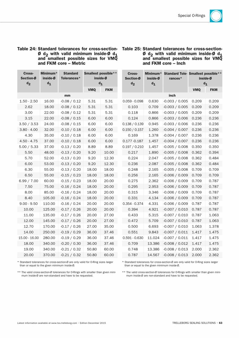
Special O-Rings
TRELLEBORG SEALING SOLUTIONS • 63Latest information available at www.tss.trelleborg.com • Edition December 2015
Table 24: Standard tolerances for cross-section- Ø d2 with valid minimum inside-Ø d1 and smallest possible sizes for VMQ and FKM core – Metric
Cross- Section-Ø
d2
Minimum* inside-Ø
d1
Standard Tolerances*
Smallest possible** inside-Ø
d1
VMQ FKM
mm
1.50 - 2.50 16.00 -0.08 / 0.12 5.31 5.31
2.62 18.00 -0.08 / 0.12 5.31 5.31
3.00 22.00 -0.08 / 0.12 5.31 5.31
3.15 22.00 -0.08 / 0.15 6.00 6.00
3.50 / 3.53 24.00 -0.08 / 0.15 6.00 6.00
3.80 - 4.00 32.00 -0.10 / 0.18 6.00 6.00
4.30 35.00 -0.10 / 0.18 6.00 6.00
4.50 - 4.75 37.00 -0.10 / 0.18 6.00 6.00
5.00 / 5.33 37.00 -0.13 / 0.20 8.89 8.89
5.50 48.00 -0.13 / 0.20 9.20 10.00
5.70 52.00 -0.13 / 0.20 9.20 12.30
6.00 53.00 -0.13 / 0.20 9.20 12.30
6.30 55.00 -0.13 / 0.20 18.00 18.00
6.50 55.00 -0.15 / 0.23 18.00 18.00
6.99 / 7.00 60.00 -0.15 / 0.23 18.00 20.00
7.50 75.00 -0.16 / 0.24 18.00 20.00
8.00 85.00 -0.16 / 0.24 18.00 20.00
8.40 105.00 -0.16 / 0.24 18.00 20.00
9.00 - 9.50 110.00 -0.16 / 0.24 20.00 20.00
10.00 125.00 -0.17 / 0.26 20.00 20.00
11.00 135.00 -0.17 / 0.26 20.00 27.00
12.00 145.00 -0.17 / 0.26 20.00 27.00
12.70 170.00 -0.17 / 0.26 27.00 35.00
14.00 250.00 -0.19 / 0.29 36.00 37.46
15.00 - 16.00 280.00 -0.19 / 0.29 36.00 37.46
18.00 340.00 -0.20 / 0.30 36.00 37.46
19.00 340.00 -0.21 / 0.32 50.80 60.00
20.00 370.00 -0.21 / 0.32 50.80 60.00
* Standard tolerances for cross-section-Ø are only valid for O-Ring sizes larger than or equal to the given minimum inside-Ø.
** The valid cross-section-Ø tolerances for O-Rings with smaller than given mini-mum inside-Ø are non-standard and have to be requested.
Table 25: Standard tolerances for cross-section- Ø d2 with valid minimum inside-Ø d1 and smallest possible sizes for VMQ and FKM core – Inch
Cross- Section-Ø
d2
Minimum* inside-Ø
d1
Standard Tole-rances*
Smallest possible** inside-Ø
d1
VMQ FKM
inch
0.059 - 0.098 0.630 -0.003 / 0.005 0.209 0.209
0.103 0.709 -0.003 / 0.005 0.209 0.209
0.118 0.866 -0.003 / 0.005 0.209 0.209
0.124 0.866 -0.003 / 0.006 0.236 0.236
0.138 / 0.139 0.945 -0.003 / 0.006 0.236 0.236
0.150 / 0.157 1.260 -0.004 / 0.007 0.236 0.236
0.169 1.378 -0.004 / 0.007 0.236 0.236
0.177 -0.187 1.457 -0.004 / 0.007 0.236 0.236
0.197 / 0.210 1.457 -0.005 / 0.008 0.350 0.350
0.217 1.890 -0.005 / 0.008 0.362 0.394
0.224 2.047 -0.005 / 0.008 0.362 0.484
0.236 2.087 -0.005 / 0.008 0.362 0.484
0.248 2.165 -0.005 / 0.008 0.709 0.709
0.256 2.165 -0.006 / 0.009 0.709 0.709
0.275 2.362 -0.006 / 0.009 0.709 0.787
0.295 2.953 -0.006 / 0.009 0.709 0.787
0.315 3.346 -0.006 / 0.009 0.709 0.787
0.331 4.134 -0.006 / 0.009 0.709 0.787
0.354 - 0.374 4.331 -0.006 / 0.009 0.787 0.787
0.394 4.921 -0.007 / 0.010 0.787 0.787
0.433 5.315 -0.007 / 0.010 0.787 1.063
0.472 5.709 -0.007 / 0.010 0.787 1.063
0.500 6.693 -0.007 / 0.010 1.063 1.378
0.551 9.843 -0.007 / 0.011 1.417 1.475
0.591 - 0.630 11.024 -0.007 / 0.011 1.417 1.475
0.709 13.386 -0.008 / 0.012 1.417 1.475
0.748 13.386 -0.008 / 0.013 2.000 2.362
0.787 14.567 -0.008 / 0.013 2.000 2.362
* Standard tolerances for cross-section-Ø are only valid for O-Ring sizes larger than or equal to the given minimum inside-Ø.
** The valid cross-section-Ø tolerances for O-Rings with smaller than given mini-mum inside-Ø are non-standard and have to be requested.
FBP_neues_Layout_2015.indb 63 17.10.2016 13:35:31
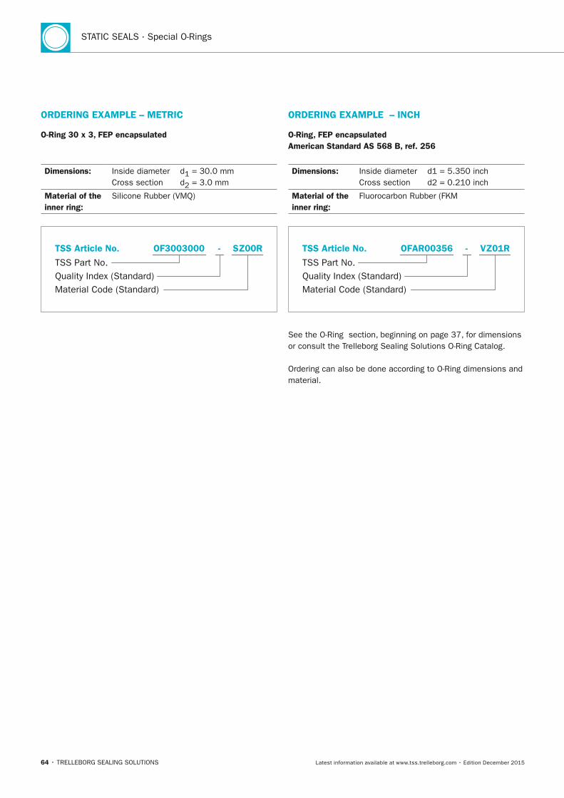
STATIC SEALS · Special O-Rings
64 • TRELLEBORG SEALING SOLUTIONS Latest information available at www.tss.trelleborg.com • Edition December 2015
ORDERInG ExAMPLE – METRIC
O-Ring 30 x 3, FEP encapsulated
Dimensions: Inside diameter d1 = 30.0 mm Cross section d2 = 3.0 mm
Material of the inner ring:
Silicone Rubber (VMQ)
TSS Part No.
TSS Article No.
Material Code (Standard)Quality Index (Standard)
OF3003000 - SZ00R
ORDERInG ExAMPLE – InCH
O-Ring, FEP encapsulated American Standard AS 568 B, ref. 256
Dimensions: Inside diameter d1 = 5.350 inch Cross section d2 = 0.210 inch
Material of the inner ring:
Fluorocarbon Rubber (FKM
TSS Part No.
TSS Article No.
Material Code (Standard)Quality Index (Standard)
OFAR00356 - VZ01R
See the O-Ring section, beginning on page 37, for dimensions or consult the Trelleborg Sealing Solutions O-Ring Catalog.
Ordering can also be done according to O-Ring dimensions and material.
FBP_neues_Layout_2015.indb 64 17.10.2016 13:35:32
STATIC SEALS
TRELLEBORG SEALING SOLUTIONS • 65Latest information available at www.tss.trelleborg.com • Edition December 2015
Clamp Seals and O-Rings for Hygienic Design Couplings Clamp Seals and O-Rings for Hygienic Design Couplings Clamp Seals and O-Rings
Hygienic design of connections
For CIP and SIP regimes
Available in FDA, EC, USP and 3-A compliant materials
Designed to ISO, DIN and ASME BPE standards
FBP_neues_Layout_2015.indb 65 17.10.2016 13:35:37

STATIC SEALS · Clamp Seals and O-Rings for Hygienic Design Couplings
66 • TRELLEBORG SEALING SOLUTIONS Latest information available at www.tss.trelleborg.com • Edition December 2015
FBP_neues_Layout_2015.indb 66 17.10.2016 13:35:37
Clamp Seals and O-Rings for Hygienic Design Couplings
TRELLEBORG SEALING SOLUTIONS • 67Latest information available at www.tss.trelleborg.com • Edition December 2015
IntroductionFilling equipment, processing and packaging machines consist of many parts that have to be connected together.
Especially in Food, Beverage and Pharmaceutical plants, along with those in Bioprocessing, a hygienic design of these connections is imperative. Only with hygienic design, proper cleaning, usually Cleaning-in-Place (CIP) followed by successful Sterilization-in-Place (SIP) is achievable.
Trelleborg Sealing Solutions offers gaskets and O-Rings for the most common standards like ISO 2852, DIN 11864, ASME BPE and DIN 32676 in high-quality materials with compliance to European Regulation (EC) 1935/2004, FDA, USP Class VI and 3-A sanitary standards.
These materials have been tested against the most commonly used cleaning fluids such as acids, alkalines and solutions with active oxygen. They have also been tested in hot water and steam with different types of water, including ultra pure deionized (UPDI) water.
Trelleborg Sealing Solutions can also provide a range of sanitary gaskets to ASME BPE standard in inch sizes. Besides the standard flanged and non-flanged versions, special designs like screen gaskets or validation gaskets can be supplied.If elastomer seals are unsuitable for a specific application then PTFE/EPDM Bonded Envelope or PTFE/Stainless Steel are available. Contact your local Trelleborg Sealing Solutions marketing company for more information.
FBP_neues_Layout_2015.indb 67 17.10.2016 13:35:37
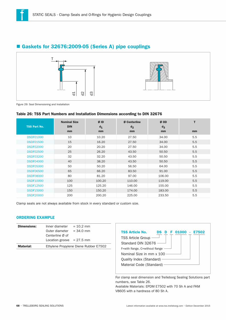
STATIC SEALS · Clamp Seals and O-Rings for Hygienic Design Couplings
68 • TRELLEBORG SEALING SOLUTIONS Latest information available at www.tss.trelleborg.com • Edition December 2015
ORDERInG ExAMPLE
Dimensions: Inner diameter = 10.2 mm Outer diameter = 34.0 mm Centerline Ø of Location groove = 27.5 mm
Material: Ethylene Propylene Diene Rubber E7502
Quality Index (Standard)
TSS Article Group
TSS Article No.
Material Code (Standard)
F=with �ange, C=without �ange
Nominal Size in mm x 100
Standard DIN 32676
- E7502DS 01000D F
For clamp seal dimension and Trelleborg Sealing Solutions part numbers, see Table 26.Available Materials: EPDM E7502 with 70 Sh A and FKM V8605 with a hardness of 80 Sh A.
� Gaskets for 32676:2009-05 (Series A) pipe couplings
d1 d2 d3
T
Figure 29: Seal Dimensioning and Installation
Table 26: TSS Part numbers and Installation Dimensions according to DIn 32676
TSS Part no.
nominal Size
DIn
mm
Ø ID
d1
mm
Ø Centerline
d2
mm
Ø OD
d3
mm
T
mm
DSDF01000 10 10.20 27.50 34.00 5.5
DSDF01500 15 16.20 27.50 34.00 5.5
DSDF02000 20 20.20 27.50 34.00 5.5
DSDF02500 25 26.20 43.50 50.50 5.5
DSDF03200 32 32.20 43.50 50.50 5.5
DSDF04000 40 38.20 43.50 50.50 5.5
DSDF05000 50 50.20 56.50 64.00 5.5
DSDF06500 65 66.20 83.50 91.00 5.5
DSDF08000 80 81.20 97.00 106.00 5.5
DSDF10000 100 100.20 110.00 119.00 5.5
DSDF12500 125 125.20 146.00 155.00 5.5
DSDF15000 150 150.20 174.00 183.00 5.5
DSDF20000 200 200.20 225.00 233.50 5.5
Clamp seals are not always available from stock in every standard or custom size.
FBP_neues_Layout_2015.indb 68 17.10.2016 13:35:38
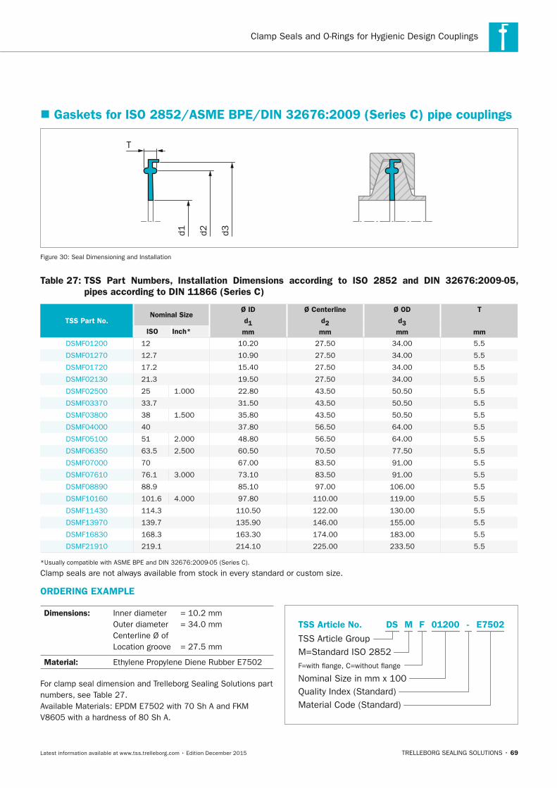
Clamp Seals and O-Rings for Hygienic Design Couplings
TRELLEBORG SEALING SOLUTIONS • 69Latest information available at www.tss.trelleborg.com • Edition December 2015
� Gaskets for ISO 2852/ASME BPE/DIn 32676:2009 (Series C) pipe couplings
d1 d2 d3
T
Figure 30: Seal Dimensioning and Installation
Table 27: TSS Part numbers, Installation Dimensions according to ISO 2852 and DIn 32676:2009-05, pipes according to DIn 11866 (Series C)
TSS Part no.nominal Size
Ø ID
d1
mm
Ø Centerline
d2
mm
Ø OD
d3
mm
T
mmISO Inch*
DSMF01200 12 10.20 27.50 34.00 5.5
DSMF01270 12.7 10.90 27.50 34.00 5.5
DSMF01720 17.2 15.40 27.50 34.00 5.5
DSMF02130 21.3 19.50 27.50 34.00 5.5
DSMF02500 25 1.000 22.80 43.50 50.50 5.5
DSMF03370 33.7 31.50 43.50 50.50 5.5
DSMF03800 38 1.500 35.80 43.50 50.50 5.5
DSMF04000 40 37.80 56.50 64.00 5.5
DSMF05100 51 2.000 48.80 56.50 64.00 5.5
DSMF06350 63.5 2.500 60.50 70.50 77.50 5.5
DSMF07000 70 67.00 83.50 91.00 5.5
DSMF07610 76.1 3.000 73.10 83.50 91.00 5.5
DSMF08890 88.9 85.10 97.00 106.00 5.5
DSMF10160 101.6 4.000 97.80 110.00 119.00 5.5
DSMF11430 114.3 110.50 122.00 130.00 5.5
DSMF13970 139.7 135.90 146.00 155.00 5.5
DSMF16830 168.3 163.30 174.00 183.00 5.5
DSMF21910 219.1 214.10 225.00 233.50 5.5
*Usually compatible with ASME BPE and DIN 32676:2009-05 (Series C).
Clamp seals are not always available from stock in every standard or custom size.
ORDERInG ExAMPLE
Dimensions: Inner diameter = 10.2 mm Outer diameter = 34.0 mm Centerline Ø of Location groove = 27.5 mm
Material: Ethylene Propylene Diene Rubber E7502
For clamp seal dimension and Trelleborg Sealing Solutions part numbers, see Table 27. Available Materials: EPDM E7502 with 70 Sh A and FKM V8605 with a hardness of 80 Sh A.
Quality Index (Standard)
TSS Article Group
TSS Article No.
Material Code (Standard)
F=with �ange, C=without �ange
Nominal Size in mm x 100
M=Standard ISO 2852
- E7502DS 01200M F
FBP_neues_Layout_2015.indb 69 17.10.2016 13:35:39
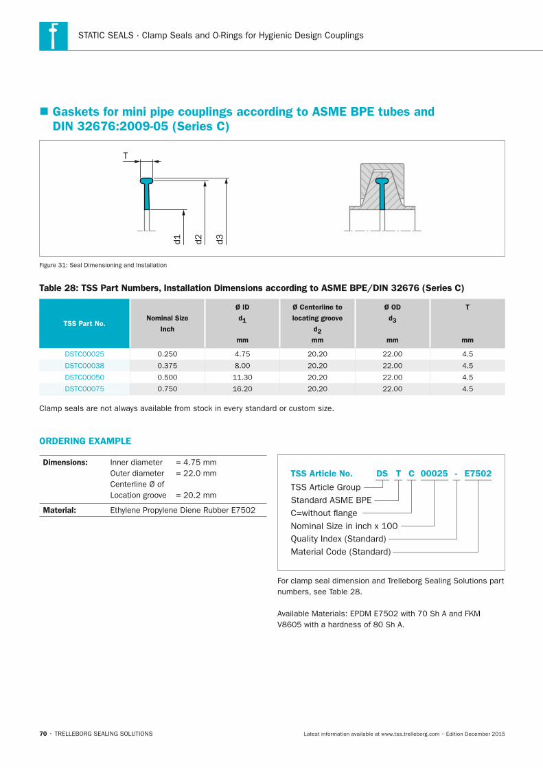
STATIC SEALS · Clamp Seals and O-Rings for Hygienic Design Couplings
70 • TRELLEBORG SEALING SOLUTIONS Latest information available at www.tss.trelleborg.com • Edition December 2015
� Gaskets for mini pipe couplings according to ASME BPE tubes and DIn 32676:2009-05 (Series C)
d1 d2 d3
T
Figure 31: Seal Dimensioning and Installation
Table 28: TSS Part numbers, Installation Dimensions according to ASME BPE/DIn 32676 (Series C)
TSS Part no.nominal Size
Inch
Ø ID
d1
mm
Ø Centerline to
locating groove
d2
mm
Ø OD
d3
mm
T
mm
DSTC00025 0.250 4.75 20.20 22.00 4.5
DSTC00038 0.375 8.00 20.20 22.00 4.5
DSTC00050 0.500 11.30 20.20 22.00 4.5
DSTC00075 0.750 16.20 20.20 22.00 4.5
Clamp seals are not always available from stock in every standard or custom size.
ORDERInG ExAMPLE
Dimensions: Inner diameter = 4.75 mm Outer diameter = 22.0 mm Centerline Ø of Location groove = 20.2 mm
Material: Ethylene Propylene Diene Rubber E7502
Quality Index (Standard)
TSS Article Group
TSS Article No.
Material Code (Standard)
C=without �angeNominal Size in inch x 100
Standard ASME BPE
- E7502DS 00025T C
For clamp seal dimension and Trelleborg Sealing Solutions part numbers, see Table 28.
Available Materials: EPDM E7502 with 70 Sh A and FKM V8605 with a hardness of 80 Sh A.
FBP_neues_Layout_2015.indb 70 17.10.2016 13:35:40
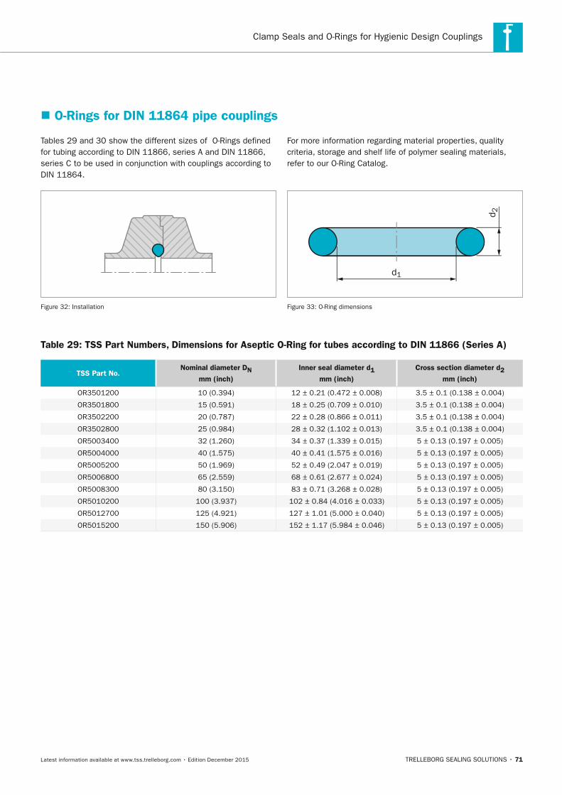
Clamp Seals and O-Rings for Hygienic Design Couplings
TRELLEBORG SEALING SOLUTIONS • 71Latest information available at www.tss.trelleborg.com • Edition December 2015
� O-Rings for DIn 11864 pipe couplings
Tables 29 and 30 show the different sizes of O-Rings defined for tubing according to DIN 11866, series A and DIN 11866, series C to be used in conjunction with couplings according to DIN 11864.
Figure 32: Installation
For more information regarding material properties, quality criteria, storage and shelf life of polymer sealing materials, refer to our O-Ring Catalog.
d 2
d1
Figure 33: O-Ring dimensions
Table 29: TSS Part numbers, Dimensions for Aseptic O-Ring for tubes according to DIn 11866 (Series A)
TSS Part no.nominal diameter Dn
mm (inch)
Inner seal diameter d1
mm (inch)
Cross section diameter d2
mm (inch)
OR3501200 10 (0.394) 12 ± 0.21 (0.472 ± 0.008) 3.5 ± 0.1 (0.138 ± 0.004)
OR3501800 15 (0.591) 18 ± 0.25 (0.709 ± 0.010) 3.5 ± 0.1 (0.138 ± 0.004)
OR3502200 20 (0.787) 22 ± 0.28 (0.866 ± 0.011) 3.5 ± 0.1 (0.138 ± 0.004)
OR3502800 25 (0.984) 28 ± 0.32 (1.102 ± 0.013) 3.5 ± 0.1 (0.138 ± 0.004)
OR5003400 32 (1.260) 34 ± 0.37 (1.339 ± 0.015) 5 ± 0.13 (0.197 ± 0.005)
OR5004000 40 (1.575) 40 ± 0.41 (1.575 ± 0.016) 5 ± 0.13 (0.197 ± 0.005)
OR5005200 50 (1.969) 52 ± 0.49 (2.047 ± 0.019) 5 ± 0.13 (0.197 ± 0.005)
OR5006800 65 (2.559) 68 ± 0.61 (2.677 ± 0.024) 5 ± 0.13 (0.197 ± 0.005)
OR5008300 80 (3.150) 83 ± 0.71 (3.268 ± 0.028) 5 ± 0.13 (0.197 ± 0.005)
OR5010200 100 (3.937) 102 ± 0.84 (4.016 ± 0.033) 5 ± 0.13 (0.197 ± 0.005)
OR5012700 125 (4.921) 127 ± 1.01 (5.000 ± 0.040) 5 ± 0.13 (0.197 ± 0.005)
OR5015200 150 (5.906) 152 ± 1.17 (5.984 ± 0.046) 5 ± 0.13 (0.197 ± 0.005)
FBP_neues_Layout_2015.indb 71 17.10.2016 13:35:40
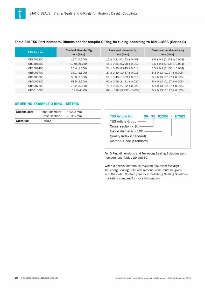
STATIC SEALS · Clamp Seals and O-Rings for Hygienic Design Couplings
72 • TRELLEBORG SEALING SOLUTIONS Latest information available at www.tss.trelleborg.com • Edition December 2015
Table 30: TSS Part numbers, Dimensions for Aseptic O-Ring for tubing according to DIn 11866 (Series C)
TSS Part no.nominal diameter Dn
mm (inch)
Inner seal diameter d1
mm (inch)
Cross section diameter d2
mm (inch)
OR3501200 12.7 (0.500) 12 ± 0.21 (0.472 ± 0.008) 3.5 ± 0.1 (0.138 ± 0.004)
OR3501800 19.05 (0.750) 18 ± 0.25 (0.708 ± 0.010) 3.5 ± 0.1 (0.138 ± 0.004)
OR3502400 25.4 (1.000) 24 ± 0.29 (0.945 ± 0.011) 3.5 ± 0.1 (0.138 ± 0.004)
OR5003700 38.1 (1.500) 37 ± 0.39 (1.457 ± 0.015) 5 ± 0.13 (0.197 ± 0.005)
OR5005000 50.8 (2.000) 50 ± 0.48 (1.969 ± 0.019) 5 ± 0.13 (0.197 ± 0.005)
OR5006200 63.5 (2.500) 62 ± 0.56 (2.441 ± 0.022) 5 ± 0.13 (0.197 ± 0.005)
OR5007500 76.2 (3.000) 75 ± 0.66 (2.952 ± 0.026) 5 ± 0.13 (0.197 ± 0.005)
OR5010000 101.6 (4.000) 100 ± 0.83 (3.937 ± 0.033) 5 ± 0.13 (0.197 ± 0.005)
ORDERInG ExAMPLE O-RInG – METRIC
Dimensions: Inner diameter = 12.0 mm Cross section = 3.5 mm
Material: E7502
Material Code (Standard)
TSS Article Group
TSS Article No.
Inside diameter x 100Quality Index (Standard)
Cross section x 10
E7502OR -35 01200
For O-Ring dimensions and Trelleborg Sealing Solutions part numbers see Tables 29 and 30.
When a special material is required, the exact five-digit Trelleborg Sealing Solutions material code must be given with the order. Contact your local Trelleborg Sealing Solutions marketing company for more information.
FBP_neues_Layout_2015.indb 72 17.10.2016 13:35:41
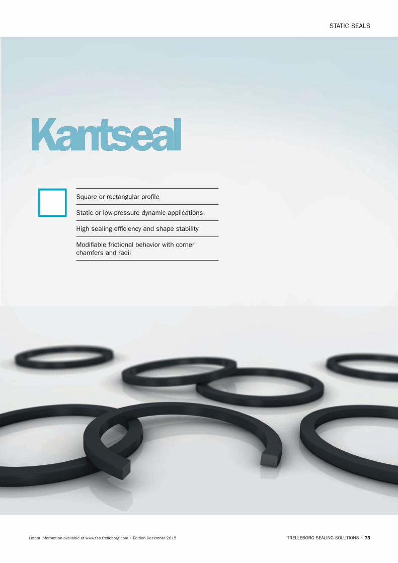
STATIC SEALS
TRELLEBORG SEALING SOLUTIONS • 73Latest information available at www.tss.trelleborg.com • Edition December 2015
KantsealSquare or rectangular profile
Static or low-pressure dynamic applications
High sealing efficiency and shape stability
Modifiable frictional behavior with corner chamfers and radii
FBP_neues_Layout_2015.indb 73 17.10.2016 13:35:43

STATIC SEALS · Kantseal
74 • TRELLEBORG SEALING SOLUTIONS Latest information available at www.tss.trelleborg.com • Edition December 2015
FBP_neues_Layout_2015.indb 74 17.10.2016 13:35:43
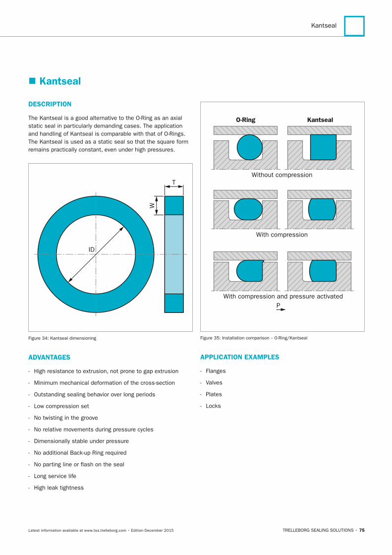
Kantseal
TRELLEBORG SEALING SOLUTIONS • 75Latest information available at www.tss.trelleborg.com • Edition December 2015
� Kantseal
DESCRIPTIOn
The Kantseal is a good alternative to the O-Ring as an axial static seal in particularly demanding cases. The application and handling of Kantseal is comparable with that of O-Rings. The Kantseal is used as a static seal so that the square form remains practically constant, even under high pressures.
ID
W
T
Figure 34: Kantseal dimensioning
ADVAnTAGES
- High resistance to extrusion, not prone to gap extrusion
- Minimum mechanical deformation of the cross-section
- Outstanding sealing behavior over long periods
- Low compression set
- No twisting in the groove
- No relative movements during pressure cycles
- Dimensionally stable under pressure
- No additional Back-up Ring required
- No parting line or flash on the seal
- Long service life
- High leak tightness
O-Ring Kantseal
Without compression
With compression
With compression and pressure activatedP
Figure 35: Installation comparison – O-Ring/Kantseal
APPLICATIOn ExAMPLES
- Flanges
- Valves
- Plates
- Locks
FBP_neues_Layout_2015.indb 75 17.10.2016 13:35:44
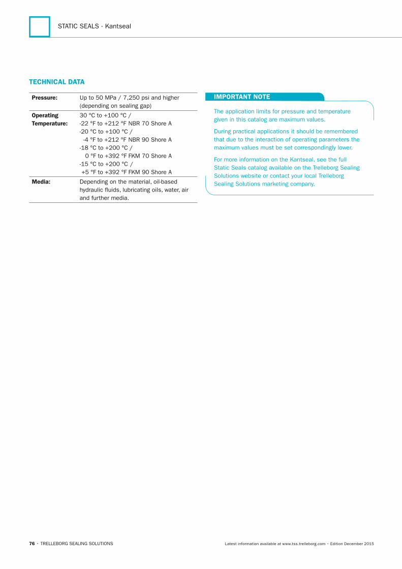
STATIC SEALS · Kantseal
76 • TRELLEBORG SEALING SOLUTIONS Latest information available at www.tss.trelleborg.com • Edition December 2015
TECHnICAL DATA
Pressure: Up to 50 MPa / 7,250 psi and higher (depending on sealing gap)
Operating Temperature:
30 °C to +100 °C / -22 °F to +212 °F NBR 70 Shore A-20 °C to +100 °C / -4 °F to +212 °F NBR 90 Shore A-18 °C to +200 °C / 0 °F to +392 °F FKM 70 Shore A-15 °C to +200 °C / +5 °F to +392 °F FKM 90 Shore A
Media: Depending on the material, oil-based hydraulic fluids, lubricating oils, water, air and further media.
IMPORTAnT nOTE
The application limits for pressure and temperature given in this catalog are maximum values.
During practical applications it should be remembered that due to the interaction of operating parameters the maximum values must be set correspondingly lower.
For more information on the Kantseal, see the full Static Seals catalog available on the Trelleborg Sealing Solutions website or contact your local Trelleborg Sealing Solutions marketing company.
FBP_neues_Layout_2015.indb 76 17.10.2016 13:35:44
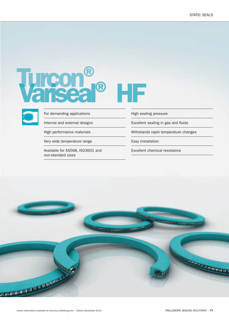
STATIC SEALS
TRELLEBORG SEALING SOLUTIONS • 77Latest information available at www.tss.trelleborg.com • Edition December 2015
Turcon®VarisealTurconVarisealTurcon ® HF
For demanding applications
Internal and external designs
High performance materials
Very wide temperature range
Available for AS568, ISO3601 and non-standard sizes
High sealing pressure
Excellent sealing in gas and fluids
Withstands rapid temperature changes
Easy installation
Excellent chemical resistance
FBP_neues_Layout_2015.indb 77 17.10.2016 13:35:46

STATIC SEALS · Turcon® Variseal® HF
78 • TRELLEBORG SEALING SOLUTIONS Latest information available at www.tss.trelleborg.com • Edition December 2015
FBP_neues_Layout_2015.indb 78 17.10.2016 13:35:46
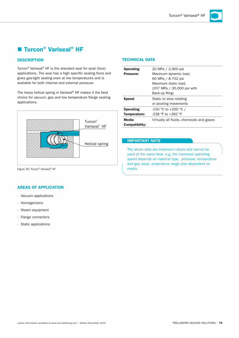
Turcon® Variseal® HF
TRELLEBORG SEALING SOLUTIONS • 79Latest information available at www.tss.trelleborg.com • Edition December 2015
� Turcon® Variseal® HF
DESCRIPTIOn
Turcon® Variseal® HF is the standard seal for axial (face) applications. The seal has a high specific sealing force and gives gas-tight sealing even at low temperatures and is available for both internal and external pressure.
The heavy helical spring in Variseal® HF makes it the best choice for vacuum, gas and low temperature flange sealing applications.
Turcon® Variseal® HF
Helical spring
Figure 36: Turcon® Variseal® HF
AREAS OF APPLICATIOn
- Vacuum applications
- Homogenizers
- Steam equipment
- Flange connectors
- Static applications
TECHnICAL DATA
Operating Pressure:
20 MPa / 2,900 psi Maximum dynamic load, 60 MPa / 8,702 psi Maximum static load, (207 MPa / 30,000 psi with Back-up Ring)
Speed: Static to slow rotating or pivoting movements
Operating Temperature:
-150 °C to +200 °C / -238 °F to +392 °F
Media Compatibility:
Virtually all fluids, chemicals and gases
IMPORTAnT nOTE
The above data are maximum values and cannot be used at the same time. e.g. the maximum operating speed depends on material type, pressure, temperature and gap value. emperature range also dependent on media.
FBP_neues_Layout_2015.indb 79 17.10.2016 13:35:47
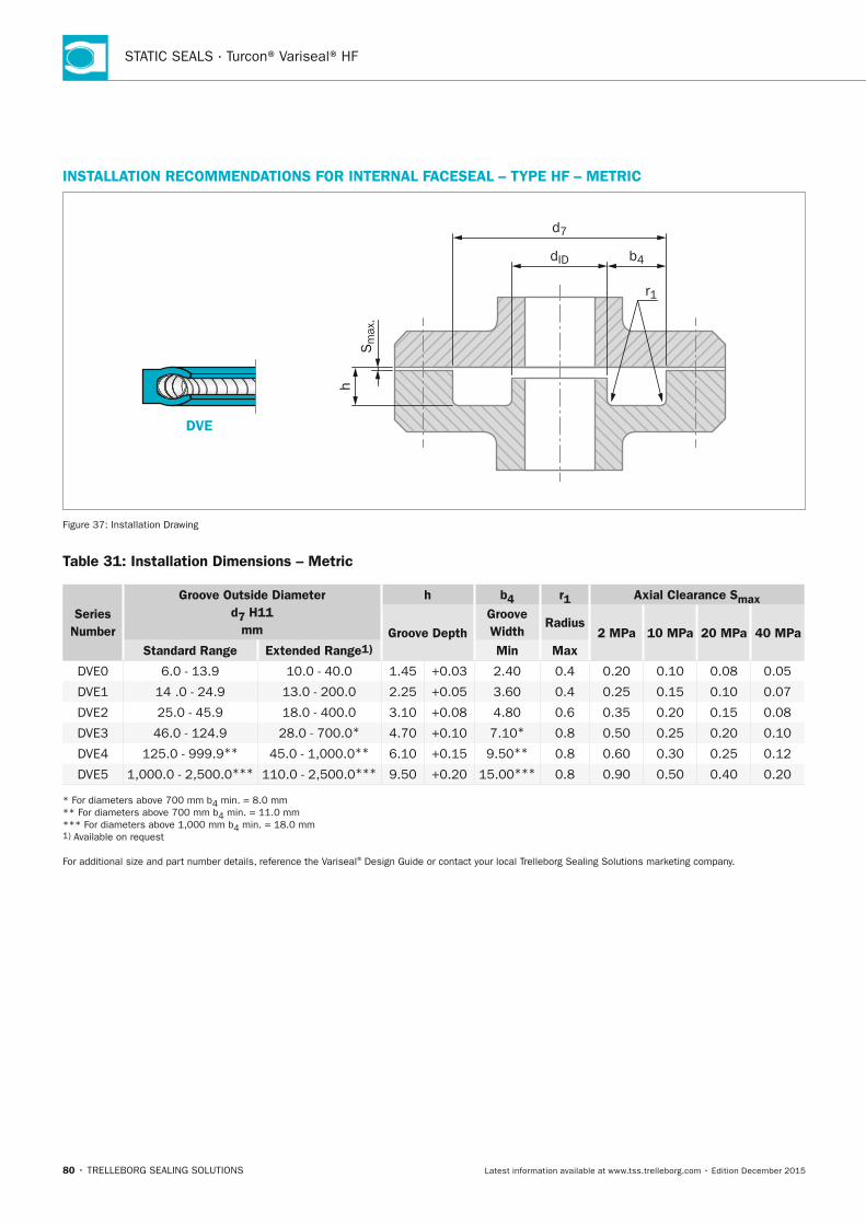
STATIC SEALS · Turcon® Variseal® HF
80 • TRELLEBORG SEALING SOLUTIONS Latest information available at www.tss.trelleborg.com • Edition December 2015
InSTALLATIOn RECOMMEnDATIOnS FOR InTERnAL FACESEAL – TyPE HF – METRIC
DVE
Sm
ax.
h
d7
dID b4
r1
Figure 37: Installation Drawing
Table 31: Installation Dimensions – Metric
Series number
Groove Outside Diameter d7 H11
mm
h b4 r1 Axial Clearance Smax
Groove DepthGroove Width
Radius2 MPa 10 MPa 20 MPa 40 MPa
Standard Range Extended Range1) Min Max
DVE0 6.0 - 13.9 10.0 - 40.0 1.45 +0.03 2.40 0.4 0.20 0.10 0.08 0.05
DVE1 14 .0 - 24.9 13.0 - 200.0 2.25 +0.05 3.60 0.4 0.25 0.15 0.10 0.07
DVE2 25.0 - 45.9 18.0 - 400.0 3.10 +0.08 4.80 0.6 0.35 0.20 0.15 0.08
DVE3 46.0 - 124.9 28.0 - 700.0* 4.70 +0.10 7.10* 0.8 0.50 0.25 0.20 0.10
DVE4 125.0 - 999.9** 45.0 - 1,000.0** 6.10 +0.15 9.50** 0.8 0.60 0.30 0.25 0.12
DVE5 1,000.0 - 2,500.0*** 110.0 - 2,500.0*** 9.50 +0.20 15.00*** 0.8 0.90 0.50 0.40 0.20
* For diameters above 700 mm b4 min. = 8.0 mm ** For diameters above 700 mm b4 min. = 11.0 mm *** For diameters above 1,000 mm b4 min. = 18.0 mm 1) Available on request
For additional size and part number details, reference the Variseal® Design Guide or contact your local Trelleborg Sealing Solutions marketing company.
FBP_neues_Layout_2015.indb 80 17.10.2016 13:35:47
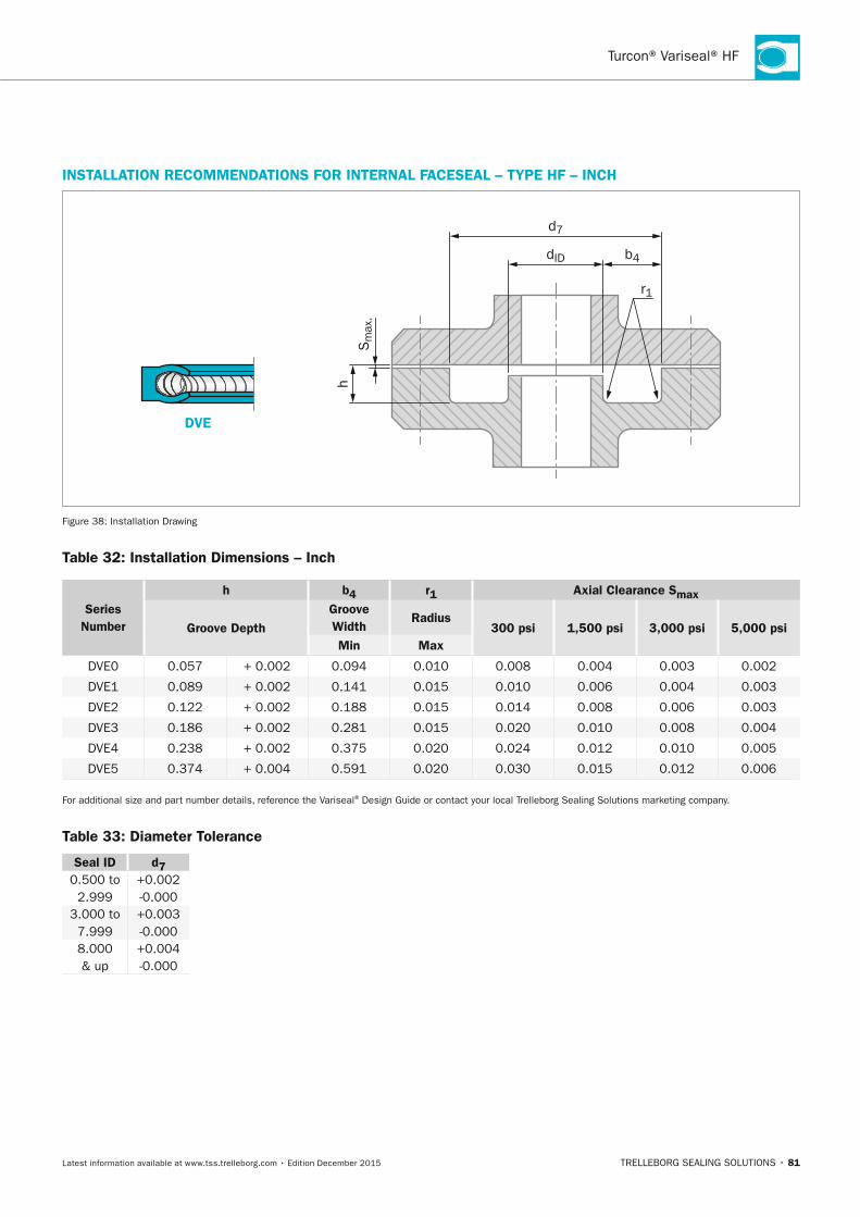
Turcon® Variseal® HF
TRELLEBORG SEALING SOLUTIONS • 81Latest information available at www.tss.trelleborg.com • Edition December 2015
InSTALLATIOn RECOMMEnDATIOnS FOR InTERnAL FACESEAL – TyPE HF – InCH
DVE
Sm
ax.
h
d7
dID b4
r1
Figure 38: Installation Drawing
Table 32: Installation Dimensions – Inch
Series number
h b4 r1 Axial Clearance Smax
Groove DepthGroove Width
Radius300 psi 1,500 psi 3,000 psi 5,000 psi
Min Max
DVE0 0.057 + 0.002 0.094 0.010 0.008 0.004 0.003 0.002
DVE1 0.089 + 0.002 0.141 0.015 0.010 0.006 0.004 0.003
DVE2 0.122 + 0.002 0.188 0.015 0.014 0.008 0.006 0.003
DVE3 0.186 + 0.002 0.281 0.015 0.020 0.010 0.008 0.004
DVE4 0.238 + 0.002 0.375 0.020 0.024 0.012 0.010 0.005
DVE5 0.374 + 0.004 0.591 0.020 0.030 0.015 0.012 0.006
For additional size and part number details, reference the Variseal® Design Guide or contact your local Trelleborg Sealing Solutions marketing company.
Table 33: Diameter Tolerance
Seal ID d70.500 to 2.999
+0.002 -0.000
3.000 to 7.999
+0.003 -0.000
8.000 & up
+0.004 -0.000
FBP_neues_Layout_2015.indb 81 17.10.2016 13:35:48
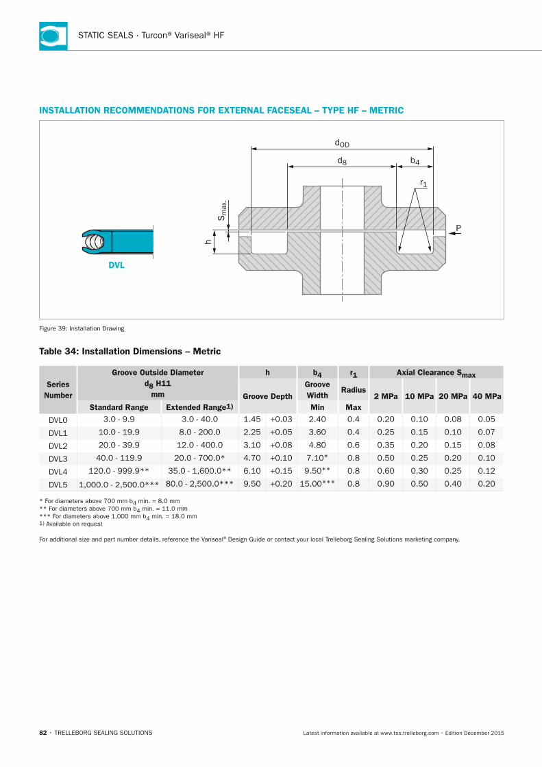
STATIC SEALS · Turcon® Variseal® HF
82 • TRELLEBORG SEALING SOLUTIONS Latest information available at www.tss.trelleborg.com • Edition December 2015
InSTALLATIOn RECOMMEnDATIOnS FOR ExTERnAL FACESEAL – TyPE HF – METRIC
DVL
Sm
ax.
h
dOD
d8 b4
r1
P
Figure 39: Installation Drawing
Table 34: Installation Dimensions – Metric
Series number
Groove Outside Diameter d8 H11
mm
h b4 r1 Axial Clearance Smax
Groove DepthGroove Width
Radius2 MPa 10 MPa 20 MPa 40 MPa
Standard Range Extended Range1) Min Max
DVL0 3.0 - 9.9 3.0 - 40.0 1.45 +0.03 2.40 0.4 0.20 0.10 0.08 0.05
DVL1 10.0 - 19.9 8.0 - 200.0 2.25 +0.05 3.60 0.4 0.25 0.15 0.10 0.07
DVL2 20.0 - 39.9 12.0 - 400.0 3.10 +0.08 4.80 0.6 0.35 0.20 0.15 0.08
DVL3 40.0 - 119.9 20.0 - 700.0* 4.70 +0.10 7.10* 0.8 0.50 0.25 0.20 0.10
DVL4 120.0 - 999.9** 35.0 - 1,600.0** 6.10 +0.15 9.50** 0.8 0.60 0.30 0.25 0.12
DVL5 1,000.0 - 2,500.0*** 80.0 - 2,500.0*** 9.50 +0.20 15.00*** 0.8 0.90 0.50 0.40 0.20
* For diameters above 700 mm b4 min. = 8.0 mm ** For diameters above 700 mm b4 min. = 11.0 mm *** For diameters above 1,000 mm b4 min. = 18.0 mm 1) Available on request
For additional size and part number details, reference the Variseal® Design Guide or contact your local Trelleborg Sealing Solutions marketing company.
FBP_neues_Layout_2015.indb 82 17.10.2016 13:35:49
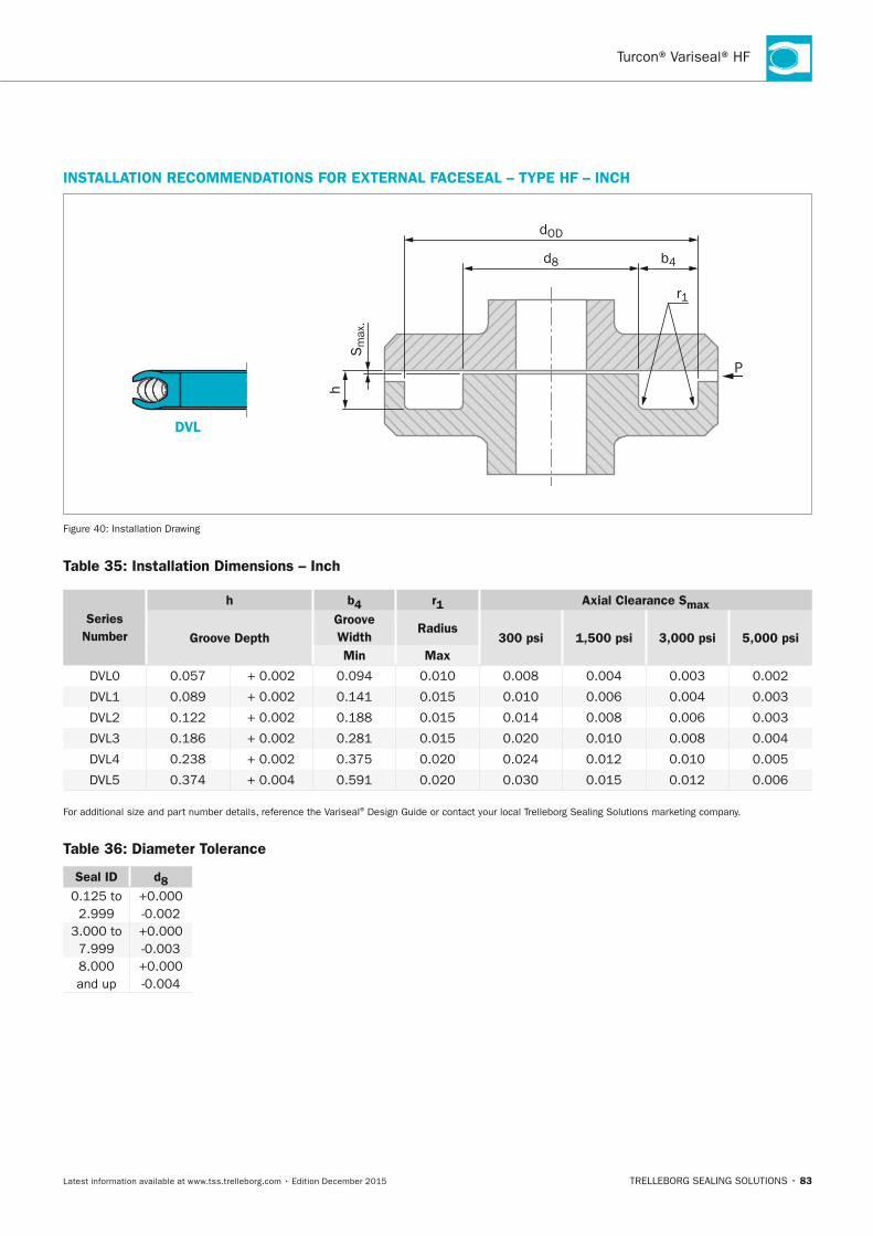
Turcon® Variseal® HF
TRELLEBORG SEALING SOLUTIONS • 83Latest information available at www.tss.trelleborg.com • Edition December 2015
InSTALLATIOn RECOMMEnDATIOnS FOR ExTERnAL FACESEAL – TyPE HF – InCH
DVL
Sm
ax.
h
dOD
d8 b4
r1
P
Figure 40: Installation Drawing
Table 35: Installation Dimensions – Inch
Series number
h b4 r1 Axial Clearance Smax
Groove DepthGroove Width
Radius300 psi 1,500 psi 3,000 psi 5,000 psi
Min Max
DVL0 0.057 + 0.002 0.094 0.010 0.008 0.004 0.003 0.002
DVL1 0.089 + 0.002 0.141 0.015 0.010 0.006 0.004 0.003
DVL2 0.122 + 0.002 0.188 0.015 0.014 0.008 0.006 0.003
DVL3 0.186 + 0.002 0.281 0.015 0.020 0.010 0.008 0.004
DVL4 0.238 + 0.002 0.375 0.020 0.024 0.012 0.010 0.005
DVL5 0.374 + 0.004 0.591 0.020 0.030 0.015 0.012 0.006
For additional size and part number details, reference the Variseal® Design Guide or contact your local Trelleborg Sealing Solutions marketing company.
Table 36: Diameter Tolerance
Seal ID d80.125 to 2.999
+0.000 -0.002
3.000 to 7.999
+0.000 -0.003
8.000 and up
+0.000 -0.004
FBP_neues_Layout_2015.indb 83 17.10.2016 13:35:49
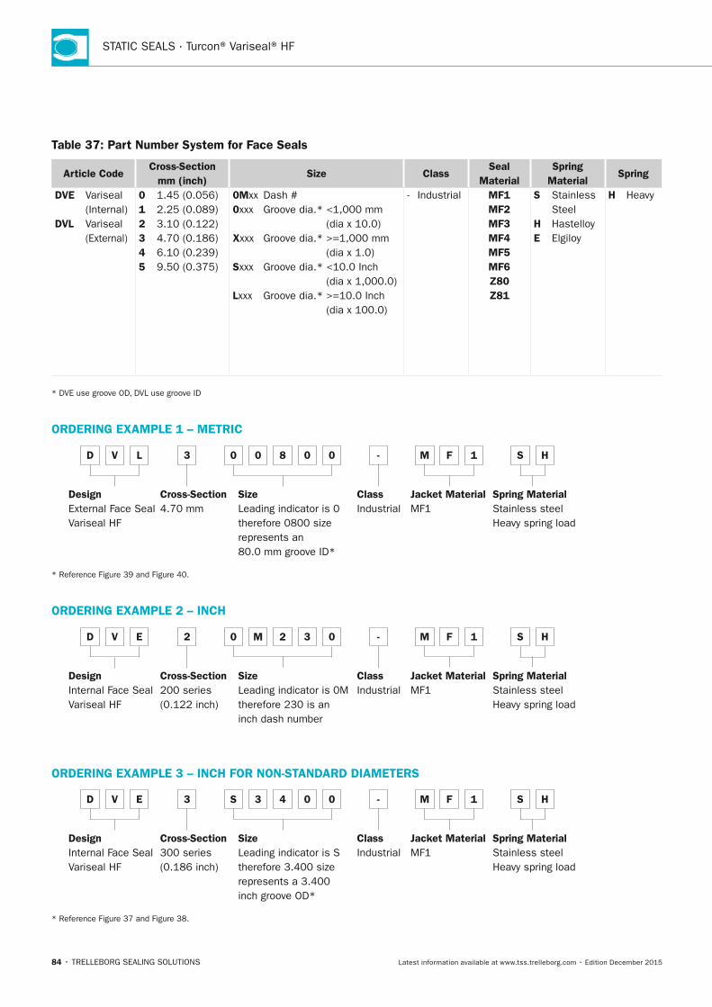
STATIC SEALS · Turcon® Variseal® HF
84 • TRELLEBORG SEALING SOLUTIONS Latest information available at www.tss.trelleborg.com • Edition December 2015
Table 37: Part number System for Face Seals
Article CodeCross-Section
mm (inch)Size Class
Seal Material
Spring Material
Spring
DVE Variseal (Internal)DVL Variseal (External)
0 1.45 (0.056)1 2.25 (0.089)2 3.10 (0.122)3 4.70 (0.186)4 6.10 (0.239)5 9.50 (0.375)
0Mxx Dash #0xxx Groove dia.* <1,000 mm
(dia x 10.0)xxxx Groove dia.* >=1,000 mm
(dia x 1.0)Sxxx Groove dia.* <10.0 Inch
(dia x 1,000.0)Lxxx Groove dia.* >=10.0 Inch
(dia x 100.0)
- Industrial MF1MF2MF3MF4MF5MF6Z80Z81
S Stainless Steel
H HastelloyE Elgiloy
H Heavy
* DVE use groove OD, DVL use groove ID
ORDERInG ExAMPLE 1 – METRIC
D V L 3 0 0 8 0 0 - M F 1 S H
DesignExternal Face SealVariseal HF
Cross-Section4.70 mm
SizeLeading indicator is 0 therefore 0800 size represents an 80.0 mm groove ID*
ClassIndustrial
Jacket MaterialMF1
Spring MaterialStainless steelHeavy spring load
* Reference Figure 39 and Figure 40.
ORDERInG ExAMPLE 2 – InCH
D V E 2 0 M 2 3 0 - M F 1 S H
DesignInternal Face SealVariseal HF
Cross-Section200 series (0.122 inch)
SizeLeading indicator is 0M therefore 230 is an inch dash number
ClassIndustrial
Jacket MaterialMF1
Spring MaterialStainless steelHeavy spring load
ORDERInG ExAMPLE 3 – InCH FOR nOn-STAnDARD DIAMETERS
D V E 3 S 3 4 0 0 - M F 1 S H
DesignInternal Face SealVariseal HF
Cross-Section300 series (0.186 inch)
SizeLeading indicator is S therefore 3.400 size represents a 3.400 inch groove OD*
ClassIndustrial
Jacket MaterialMF1
Spring MaterialStainless steelHeavy spring load
* Reference Figure 37 and Figure 38.
FBP_neues_Layout_2015.indb 84 17.10.2016 13:35:50
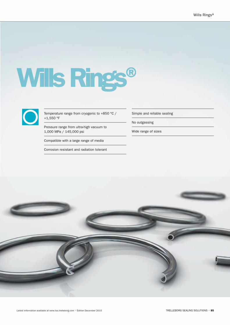
Wills Rings®
TRELLEBORG SEALING SOLUTIONS • 85Latest information available at www.tss.trelleborg.com • Edition December 2015
Wills Rings®Wills Rings®Wills RingsTemperature range from cryogenic to +850 °C / +1,550 °F
Pressure range from ultra-high vacuum to 1,000 MPa / 145,000 psi
Compatible with a large range of media
Corrosion resistant and radiation tolerant
Simple and reliable sealing
No outgassing
Wide range of sizes
FBP_neues_Layout_2015.indb 85 17.10.2016 13:35:52

STATIC SEALS · Wills Rings®
86 • TRELLEBORG SEALING SOLUTIONS Latest information available at www.tss.trelleborg.com • Edition December 2015
FBP_neues_Layout_2015.indb 86 17.10.2016 13:35:52
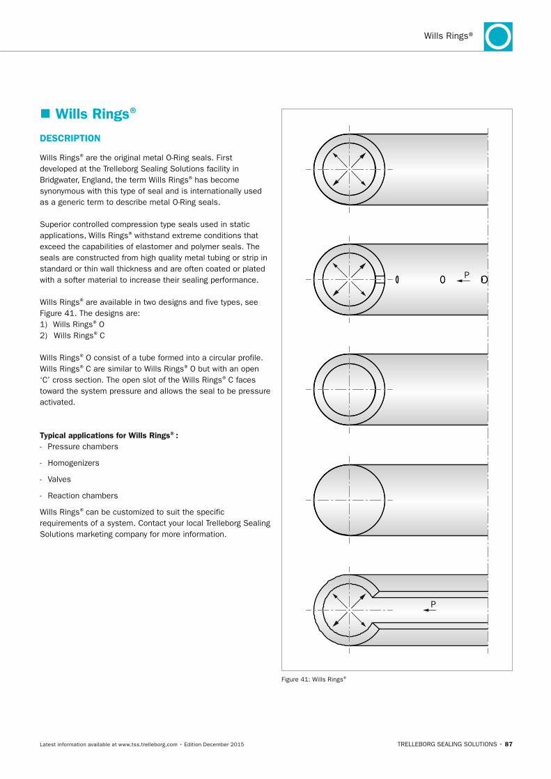
TRELLEBORG SEALING SOLUTIONS • 87Latest information available at www.tss.trelleborg.com • Edition December 2015
Wills Rings®
� Wills Rings®
DESCRIPTIOn
Wills Rings® are the original metal O-Ring seals. First developed at the Trelleborg Sealing Solutions facility in Bridgwater, England, the term Wills Rings® has become synonymous with this type of seal and is internationally used as a generic term to describe metal O-Ring seals.
Superior controlled compression type seals used in static applications, Wills Rings® withstand extreme conditions that exceed the capabilities of elastomer and polymer seals. The seals are constructed from high quality metal tubing or strip in standard or thin wall thickness and are often coated or plated with a softer material to increase their sealing performance.
Wills Rings® are available in two designs and five types, see Figure 41. The designs are:1) Wills Rings® O2) Wills Rings® C
Wills Rings® O consist of a tube formed into a circular profile. Wills Rings® C are similar to Wills Rings® O but with an open ‘C’ cross section. The open slot of the Wills Rings® C faces toward the system pressure and allows the seal to be pressure activated.
Typical applications for Wills Rings®: - Pressure chambers
- Homogenizers
- Valves
- Reaction chambers
Wills Rings® can be customized to suit the specific requirements of a system. Contact your local Trelleborg Sealing Solutions marketing company for more information.
P
P
Figure 41: Wills Rings®
FBP_neues_Layout_2015.indb 87 17.10.2016 13:35:52
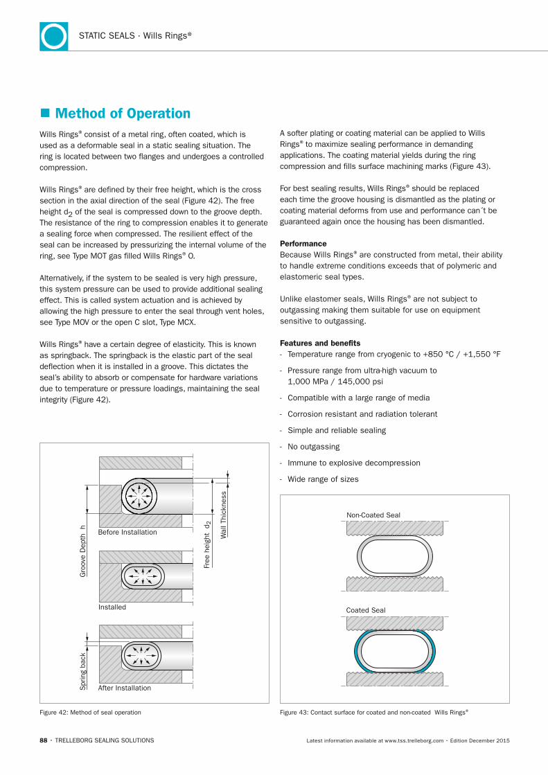
88 • TRELLEBORG SEALING SOLUTIONS Latest information available at www.tss.trelleborg.com • Edition December 2015
STATIC SEALS · Wills Rings®
� Method of Operation Wills Rings® consist of a metal ring, often coated, which is used as a deformable seal in a static sealing situation. The ring is located between two flanges and undergoes a controlled compression.
Wills Rings® are defined by their free height, which is the cross section in the axial direction of the seal (Figure 42). The free height d2 of the seal is compressed down to the groove depth. The resistance of the ring to compression enables it to generate a sealing force when compressed. The resilient effect of the seal can be increased by pressurizing the internal volume of the ring, see Type MOT gas filled Wills Rings® O.
Alternatively, if the system to be sealed is very high pressure, this system pressure can be used to provide additional sealing effect. This is called system actuation and is achieved by allowing the high pressure to enter the seal through vent holes, see Type MOV or the open C slot, Type MCX.
Wills Rings® have a certain degree of elasticity. This is known as springback. The springback is the elastic part of the seal deflection when it is installed in a groove. This dictates the seal’s ability to absorb or compensate for hardware variations due to temperature or pressure loadings, maintaining the seal integrity (Figure 42).
Before Installation
After Installation
Installed
Wal
l Thi
ckne
ss
Gro
ove
Dep
th h
Free
hei
ght
d2
Spr
ing
back
Figure 42: Method of seal operation
A softer plating or coating material can be applied to Wills Rings® to maximize sealing performance in demanding applications. The coating material yields during the ring compression and fills surface machining marks (Figure 43).
For best sealing results, Wills Rings® should be replaced each time the groove housing is dismantled as the plating or coating material deforms from use and performance can´t be guaranteed again once the housing has been dismantled.
PerformanceBecause Wills Rings® are constructed from metal, their ability to handle extreme conditions exceeds that of polymeric and elastomeric seal types.
Unlike elastomer seals, Wills Rings® are not subject to outgassing making them suitable for use on equipment sensitive to outgassing.
Features and benefits - Temperature range from cryogenic to +850 °C / +1,550 °F
- Pressure range from ultra-high vacuum to 1,000 MPa / 145,000 psi
- Compatible with a large range of media
- Corrosion resistant and radiation tolerant
- Simple and reliable sealing
- No outgassing
- Immune to explosive decompression
- Wide range of sizes
Non-Coated Seal
Coated Seal
Figure 43: Contact surface for coated and non-coated Wills Rings®
FBP_neues_Layout_2015.indb 88 17.10.2016 13:35:53
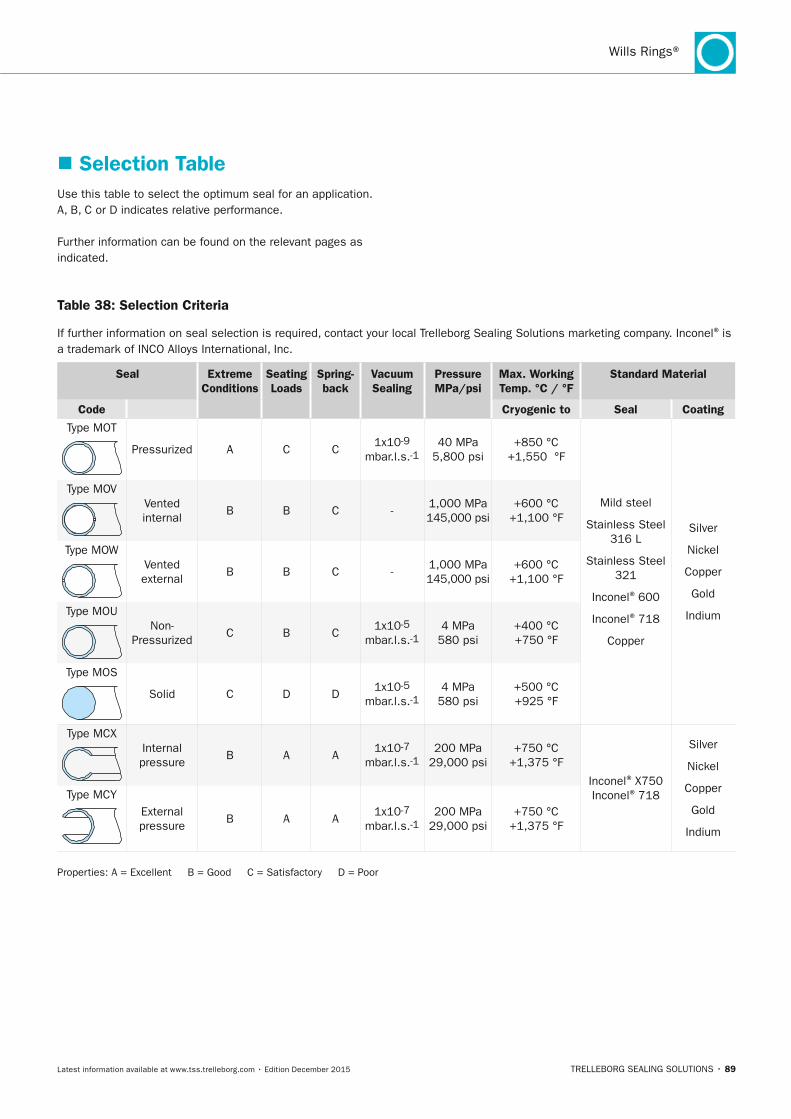
TRELLEBORG SEALING SOLUTIONS • 89Latest information available at www.tss.trelleborg.com • Edition December 2015
Wills Rings®
Table 38: Selection Criteria
If further information on seal selection is required, contact your local Trelleborg Sealing Solutions marketing company. Inconel® is a trademark of INCO Alloys International, Inc.
Seal Extreme Conditions
Seating Loads
Spring-back
Vacuum Sealing
Pressure MPa/psi
Max. Working Temp. °C / °F
Standard Material
Code Cryogenic to Seal Coating
Type MOT
Pressurized A C C 1x10⁻⁹
mbar.l.s.-140 MPa
5,800 psi+850 °C
+1,550 °F
Mild steel
Stainless Steel 316 L
Stainless Steel 321
Inconel® 600
Inconel® 718
Copper
Silver
Nickel
Copper
Gold
Indium
Type MOVVented internal
B B C -1,000 MPa 145,000 psi
+600 °C +1,100 °F
Type MOWVented external
B B C -1,000 MPa 145,000 psi
+600 °C +1,100 °F
Type MOUNon-
PressurizedC B C
1x10⁻⁵ mbar.l.s.-1
4 MPa 580 psi
+400 °C +750 °F
Type MOS
Solid C D D1x10-5
mbar.l.s.-1 4 MPa
580 psi +500 °C +925 °F
Type MCXInternal pressure
B A A1x10-7
mbar.l.s.-1 200 MPa
29,000 psi+750 °C
+1,375 °F
Inconel® X750 Inconel® 718
Silver
Nickel
Copper
Gold
Indium
Type MCYExternal pressure
B A A1x10-7
mbar.l.s.-1 200 MPa
29,000 psi+750 °C
+1,375 °F
Properties: A = Excellent B = Good C = Satisfactory D = Poor
� Selection Table Use this table to select the optimum seal for an application. A, B, C or D indicates relative performance.
Further information can be found on the relevant pages as indicated.
FBP_neues_Layout_2015.indb 89 17.10.2016 13:35:54
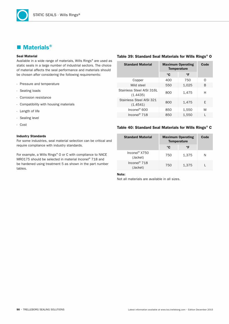
90 • TRELLEBORG SEALING SOLUTIONS Latest information available at www.tss.trelleborg.com • Edition December 2015
STATIC SEALS · Wills Rings®
� Materials®
Seal MaterialAvailable in a wide range of materials, Wills Rings® are used as static seals in a large number of industrial sectors. The choice of material affects the seal performance and materials should be chosen after considering the following requirements:
- Pressure and temperature
- Seating loads
- Corrosion resistance
- Compatibility with housing materials
- Length of life
- Sealing level
- Cost
Industry StandardsFor some industries, seal material selection can be critical and require compliance with industry standards.
For example, a Wills Rings® O or C with compliance to NACE MR0175 should be selected in material Inconel® 718 and be hardened using treatment 5 as shown in the part number tables.
Table 39: Standard Seal Materials for Wills Rings® O
Standard Material Maximum Operating Temperature
Code
°C °F
Copper 400 750 O
Mild steel 550 1,025 B
Stainless Steel AISI 316L (1.4435)
800 1,475 H
Stainless Steel AISI 321 (1.4541)
800 1,475 E
Inconel® 600 850 1,550 M
Inconel® 718 850 1,550 L
Table 40: Standard Seal Materials for Wills Rings® C
Standard Material Maximum Operating Temperature
Code
°C °F
Inconel® X750 (Jacket)
750 1,375 N
Inconel® 718 (Jacket)
750 1,375 L
note:Not all materials are available in all sizes.
FBP_neues_Layout_2015.indb 90 17.10.2016 13:35:54
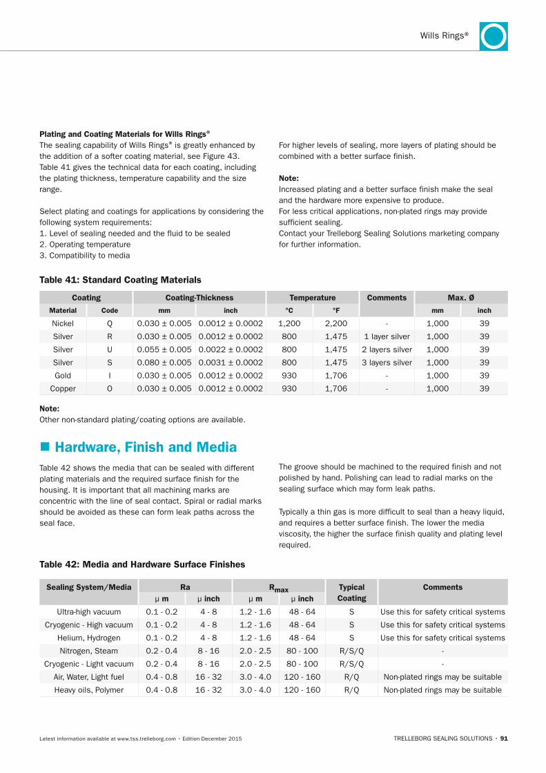
TRELLEBORG SEALING SOLUTIONS • 91Latest information available at www.tss.trelleborg.com • Edition December 2015
Wills Rings®
Plating and Coating Materials for Wills Rings®
The sealing capability of Wills Rings® is greatly enhanced by the addition of a softer coating material, see Figure 43. Table 41 gives the technical data for each coating, including the plating thickness, temperature capability and the size range.
Select plating and coatings for applications by considering the following system requirements:1. Level of sealing needed and the fluid to be sealed2. Operating temperature3. Compatibility to media
For higher levels of sealing, more layers of plating should be combined with a better surface finish.
note:Increased plating and a better surface finish make the seal and the hardware more expensive to produce.For less critical applications, non-plated rings may provide sufficient sealing.Contact your Trelleborg Sealing Solutions marketing company for further information.
Table 41: Standard Coating Materials
Coating Coating-Thickness Temperature Comments Max. Ø
Material Code mm inch °C °F mm inch
Nickel Q 0.030 ± 0.005 0.0012 ± 0.0002 1,200 2,200 - 1,000 39
Silver R 0.030 ± 0.005 0.0012 ± 0.0002 800 1,475 1 layer silver 1,000 39
Silver U 0.055 ± 0.005 0.0022 ± 0.0002 800 1,475 2 layers silver 1,000 39
Silver S 0.080 ± 0.005 0.0031 ± 0.0002 800 1,475 3 layers silver 1,000 39
Gold I 0.030 ± 0.005 0.0012 ± 0.0002 930 1,706 - 1,000 39
Copper O 0.030 ± 0.005 0.0012 ± 0.0002 930 1,706 - 1,000 39
note: Other non-standard plating/coating options are available.
� Hardware, Finish and MediaTable 42 shows the media that can be sealed with different plating materials and the required surface finish for the housing. It is important that all machining marks are concentric with the line of seal contact. Spiral or radial marks should be avoided as these can form leak paths across the seal face.
The groove should be machined to the required finish and not polished by hand. Polishing can lead to radial marks on the sealing surface which may form leak paths.
Typically a thin gas is more difficult to seal than a heavy liquid, and requires a better surface finish. The lower the media viscosity, the higher the surface finish quality and plating level required.
Table 42: Media and Hardware Surface Finishes
Sealing System/Media Ra Rmax Typical Coating
Commentsµ m µ inch µ m µ inch
Ultra-high vacuum 0.1 - 0.2 4 - 8 1.2 - 1.6 48 - 64 S Use this for safety critical systems
Cryogenic - High vacuum 0.1 - 0.2 4 - 8 1.2 - 1.6 48 - 64 S Use this for safety critical systems
Helium, Hydrogen 0.1 - 0.2 4 - 8 1.2 - 1.6 48 - 64 S Use this for safety critical systems
Nitrogen, Steam 0.2 - 0.4 8 - 16 2.0 - 2.5 80 - 100 R/S/Q -
Cryogenic - Light vacuum 0.2 - 0.4 8 - 16 2.0 - 2.5 80 - 100 R/S/Q -
Air, Water, Light fuel 0.4 - 0.8 16 - 32 3.0 - 4.0 120 - 160 R/Q Non-plated rings may be suitable
Heavy oils, Polymer 0.4 - 0.8 16 - 32 3.0 - 4.0 120 - 160 R/Q Non-plated rings may be suitable
FBP_neues_Layout_2015.indb 91 17.10.2016 13:35:55
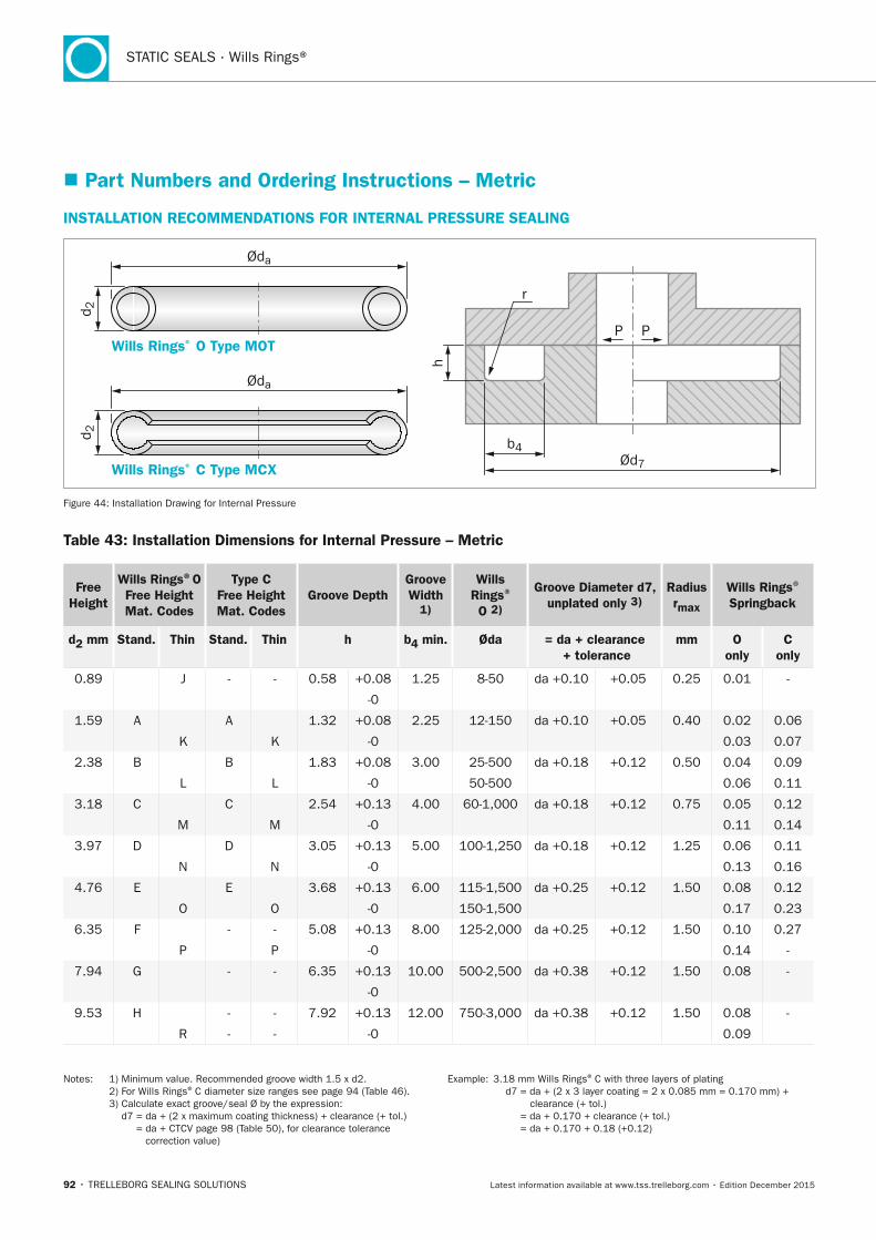
92 • TRELLEBORG SEALING SOLUTIONS Latest information available at www.tss.trelleborg.com • Edition December 2015
STATIC SEALS · Wills Rings®
� Part numbers and Ordering Instructions – Metric
InSTALLATIOn RECOMMEnDATIOnS FOR InTERnAL PRESSURE SEALInG
Wills Rings® O Type MOT
Wills Rings® C Type MCX
d 2d 2
P P
h
Ød7
Øda
Øda
b4
r
Figure 44: Installation Drawing for Internal Pressure
Table 43: Installation Dimensions for Internal Pressure – Metric
Free Height
Wills Rings®O Free Height Mat. Codes
Type C Free Height Mat. Codes
Groove DepthGroove Width
1)
Wills Rings®
O 2)
Groove Diameter d7, unplated only 3)
Radius rmax
Wills Rings®
Springback
d2 mm Stand. Thin Stand. Thin h b4 min. Øda = da + clearance + tolerance
mm O only
C only
0.89 J - - 0.58 +0.08 1.25 8-50 da +0.10 +0.05 0.25 0.01 -
-0
1.59 A A 1.32 +0.08 2.25 12-150 da +0.10 +0.05 0.40 0.02 0.06
K K -0 0.03 0.07
2.38 B B 1.83 +0.08 3.00 25-500 da +0.18 +0.12 0.50 0.04 0.09
L L -0 50-500 0.06 0.11
3.18 C C 2.54 +0.13 4.00 60-1,000 da +0.18 +0.12 0.75 0.05 0.12
M M -0 0.11 0.14
3.97 D D 3.05 +0.13 5.00 100-1,250 da +0.18 +0.12 1.25 0.06 0.11
N N -0 0.13 0.16
4.76 E E 3.68 +0.13 6.00 115-1,500 da +0.25 +0.12 1.50 0.08 0.12
O O -0 150-1,500 0.17 0.23
6.35 F - - 5.08 +0.13 8.00 125-2,000 da +0.25 +0.12 1.50 0.10 0.27
P P -0 0.14 -
7.94 G - - 6.35 +0.13 10.00 500-2,500 da +0.38 +0.12 1.50 0.08 -
-0
9.53 H - - 7.92 +0.13 12.00 750-3,000 da +0.38 +0.12 1.50 0.08 -
R - - -0 0.09
Notes: 1) Minimum value. Recommended groove width 1.5 x d2. 2) For Wills Rings® C diameter size ranges see page 94 (Table 46). 3) Calculate exact groove/seal Ø by the expression: d7 = da + (2 x maximum coating thickness) + clearance (+ tol.)
= da + CTCV page 98 (Table 50), for clearance tolerance correction value)
Example: 3.18 mm Wills Rings® C with three layers of plating d7 = da + (2 x 3 layer coating = 2 x 0.085 mm = 0.170 mm) +
clearance (+ tol.) = da + 0.170 + clearance (+ tol.) = da + 0.170 + 0.18 (+0.12)
FBP_neues_Layout_2015.indb 92 17.10.2016 13:35:55
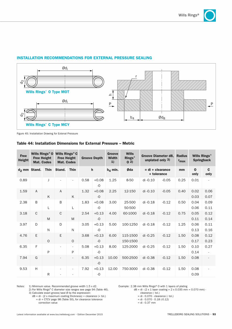
TRELLEBORG SEALING SOLUTIONS • 93Latest information available at www.tss.trelleborg.com • Edition December 2015
Wills Rings®
InSTALLATIOn RECOMMEnDATIOnS FOR ExTERnAL PRESSURE SEALInG
Wills Rings® O Type MOT
Wills Rings® C Type MCY
PP
h
Ød8b4
d 2d 2
Ødi
Ødi
r
Figure 45: Installation Drawing for Extenal Pressure
Table 44: Installation Dimensions for External Pressure – Metric
Free Height
Wills Rings®O Free Height Mat. Codes
Wills Rings®C Free Height Mat. Codes
Groove DepthGroove Width
1)
Wills Rings®
O 2)
Groove Diameter d8, unplated only 3)
Radius rmax
Wills Rings®
Springback
d2 mm Stand. Thin Stand. Thin h b4 min. Øda = di + clearance + tolerance
mm O only
C only
0.89 J - - 0.58 +0.08 1.25 8-50 di -0.10 -0.05 0.25 0.01 -
-0
1.59 A A 1.32 +0.08 2.25 12-150 di -0.10 -0.05 0.40 0.02 0.06
K K -0 0.03 0.07
2.38 B B 1.83 +0.08 3.00 25-500 di -0.18 -0.12 0.50 0.04 0.09
L L -0 50-500 0.06 0.11
3.18 C C 2.54 +0.13 4.00 60-1000 di -0.18 -0.12 0.75 0.05 0.12
M M -0 0.11 0.14
3.97 D D 3.05 +0.13 5.00 100-1250 di -0.18 -0.12 1.25 0.06 0.11
N N -0 0.13 0.16
4.76 E E 3.68 +0.13 6.00 115-1500 di -0.25 -0.12 1.50 0.08 0.12
O O -0 150-1500 0.17 0.23
6.35 F - - 5.08 +0.13 8.00 125-2000 di -0.25 -0.12 1.50 0.10 0.27
P P -0 0.14 -
7.94 G - - 6.35 +0.13 10.00 500-2500 di -0.38 -0.12 1.50 0.08 -
-0
9.53 H - - 7.92 +0.13 12.00 750-3000 di -0.38 -0.12 1.50 0.08 -
R - - -0 0.09
Notes: 1) Minimum value. Recommended groove width 1.5 x d2. 2) For Wills Rings® C diameter size ranges see page 94 (Table 46). 3) Calculate exact groove/seal Ø by the expression: d8 = di - (2 x maximum coating thickness) + clearance (+ tol.)
= di + CTCV page 98 (Table 50), for clearance tolerance correction value
Example: 2.38 mm Wills Rings® O with 1 layers of plating d8 = di - (2 x 1 layer coating = 2 x 0.035 mm = 0.070 mm) -
clearance (- tol.) = di - 0.070 - clearance (- tol.) = di - 0.070 - 0.18 (-0.12) = di - 0.37 mm
FBP_neues_Layout_2015.indb 93 17.10.2016 13:35:56
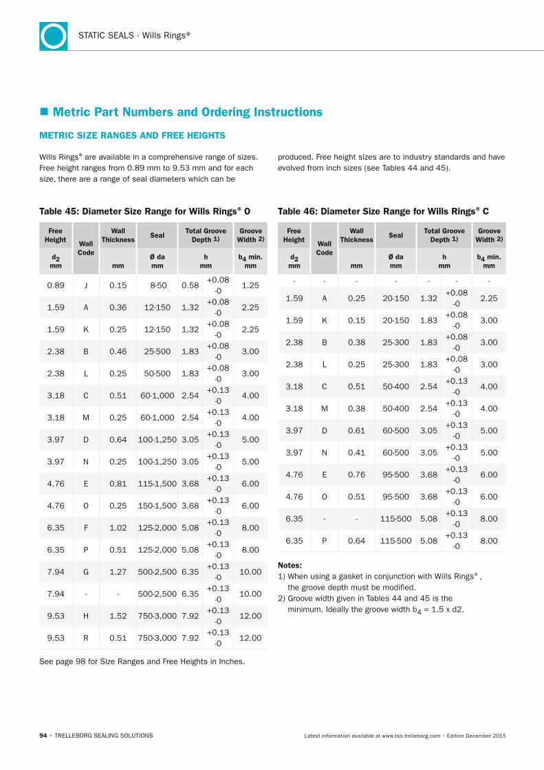
94 • TRELLEBORG SEALING SOLUTIONS Latest information available at www.tss.trelleborg.com • Edition December 2015
STATIC SEALS · Wills Rings®
� Metric Part numbers and Ordering Instructions
METRIC SIZE RAnGES AnD FREE HEIGHTS
Wills Rings® are available in a comprehensive range of sizes. Free height ranges from 0.89 mm to 9.53 mm and for each size, there are a range of seal diameters which can be
produced. Free height sizes are to industry standards and have evolved from inch sizes (see Tables 44 and 45).
Table 45: Diameter Size Range for Wills Rings® O
Free Height Wall
Code
Wall Thickness
SealTotal Groove
Depth 1)Groove
Width 2)
d2 mm
mm
Ø da mm
h mm
b4 min. mm
0.89 J 0.15 8-50 0.58+0.08
-01.25
1.59 A 0.36 12-150 1.32+0.08
-02.25
1.59 K 0.25 12-150 1.32+0.08
-02.25
2.38 B 0.46 25-500 1.83+0.08
-03.00
2.38 L 0.25 50-500 1.83+0.08
-03.00
3.18 C 0.51 60-1,000 2.54+0.13
-04.00
3.18 M 0.25 60-1,000 2.54+0.13
-04.00
3.97 D 0.64 100-1,250 3.05+0.13
-05.00
3.97 N 0.25 100-1,250 3.05+0.13
-05.00
4.76 E 0.81 115-1,500 3.68+0.13
-06.00
4.76 O 0.25 150-1,500 3.68+0.13
-06.00
6.35 F 1.02 125-2,000 5.08+0.13
-08.00
6.35 P 0.51 125-2,000 5.08+0.13
-08.00
7.94 G 1.27 500-2,500 6.35+0.13
-010.00
7.94 - - 500-2,500 6.35+0.13
-010.00
9.53 H 1.52 750-3,000 7.92+0.13
-012.00
9.53 R 0.51 750-3,000 7.92+0.13
-012.00
See page 98 for Size Ranges and Free Heights in Inches.
Table 46: Diameter Size Range for Wills Rings® C
Free Height Wall
Code
Wall Thickness
SealTotal Groove
Depth 1)Groove
Width 2)
d2 mm
mm
Ø da mm
h mm
b4 min. mm
- - - - - - -
1.59 A 0.25 20-150 1.32+0.08
-02.25
1.59 K 0.15 20-150 1.83+0.08
-03.00
2.38 B 0.38 25-300 1.83+0.08
-03.00
2.38 L 0.25 25-300 1.83+0.08
-03.00
3.18 C 0.51 50-400 2.54+0.13
-04.00
3.18 M 0.38 50-400 2.54+0.13
-04.00
3.97 D 0.61 60-500 3.05+0.13
-05.00
3.97 N 0.41 60-500 3.05+0.13
-05.00
4.76 E 0.76 95-500 3.68+0.13
-06.00
4.76 O 0.51 95-500 3.68+0.13
-06.00
6.35 - - 115-500 5.08+0.13
-08.00
6.35 P 0.64 115-500 5.08+0.13
-08.00
notes: 1) When using a gasket in conjunction with Wills Rings®,
the groove depth must be modified.2) Groove width given in Tables 44 and 45 is the
minimum. Ideally the groove width b4 = 1.5 x d2.
FBP_neues_Layout_2015.indb 94 17.10.2016 13:35:56
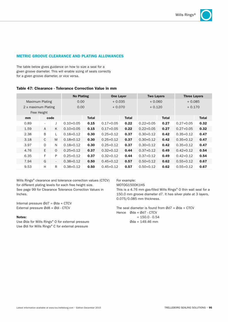
TRELLEBORG SEALING SOLUTIONS • 95Latest information available at www.tss.trelleborg.com • Edition December 2015
Wills Rings®
METRIC GROOVE CLEARAnCE AnD PLATInG ALLOWAnCES
Wills Rings® clearance and tolerance correction values (CTCV) for different plating levels for each free height size.See page 99 for Clearance Tolerance Correction Values in Inches.
Internal pressure Ød7 = Øda + CTCVExternal pressure Ød8 = Ødi - CTCV
notes:Use Øda for Wills Rings® O for external pressure Use Ødi for Wills Rings® C for external pressure
For example:MOTOG1500K1HS This is a 4.76 mm gas-filled Wills Rings® O thin wall seal for a 150.0 mm groove diameter d7. It has silver plate at 3 layers, 0.075/0.085 mm thickness.
The seal diameter is found from Ød7 = Øda + CTCVHence Øda = Ød7 - CTCV
= 150.0 - 0.54 Øda = 149.46 mm
Table 47: Clearance - Tolerance Correction Value in mm
no Plating One Layer Two Layers Three Layers
Maximum Plating 0.00 + 0.035 + 0.060 + 0.085
2 x maximum Plating 0.00 + 0.070 + 0.120 + 0.170
Free Height
mm code Total Total Total Total
0.89 - J 0.10+0.05 0.15 0.17+0.05 0.22 0.22+0.05 0.27 0.27+0.05 0.32
1.59 A K 0.10+0.05 0.15 0.17+0.05 0.22 0.22+0.05 0.27 0.27+0.05 0.32
2.38 B L 0.18+0.12 0.30 0.25+0.12 0.37 0.30+0.12 0.42 0.35+0.12 0.47
3.18 C M 0.18+0.12 0.30 0.25+0.12 0.37 0.30+0.12 0.42 0.35+0.12 0.47
3.97 D N 0.18+0.12 0.30 0.25+0.12 0.37 0.30+0.12 0.42 0.35+0.12 0.47
4.76 E O 0.25+0.12 0.37 0.32+0.12 0.44 0.37+0.12 0.49 0.42+0.12 0.54
6.35 F P 0.25+0.12 0.37 0.32+0.12 0.44 0.37+0.12 0.49 0.42+0.12 0.54
7.94 G - 0.38+0.12 0.50 0.45+0.12 0.57 0.50+0.12 0.62 0.55+0.12 0.67
9.53 H R 0.38+0.12 0.50 0.45+0.12 0.57 0.50+0.12 0.62 0.55+0.12 0.67
The table below gives guidance on how to size a seal for a given groove diameter. This will enable sizing of seals correctly for a given groove diameter, or vice versa.
FBP_neues_Layout_2015.indb 95 17.10.2016 13:35:57
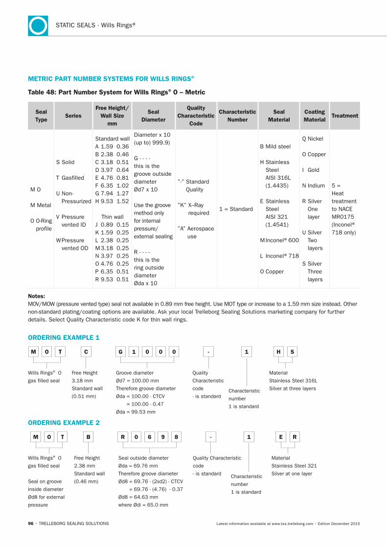
96 • TRELLEBORG SEALING SOLUTIONS Latest information available at www.tss.trelleborg.com • Edition December 2015
STATIC SEALS · Wills Rings®
METRIC PART nUMBER SySTEMS FOR WILLS RInGS®
Table 48: Part number System for Wills Rings® O – Metric
Seal Type
SeriesFree Height/
Wall Size mm
Seal Diameter
Quality Characteristic
Code
Characteristic number
Seal Material
Coating Material
Treatment
M O
M Metal
O O-Ring profile
S Solid
T Gasfilled
U Non- Pressurized
V Pressure vented ID
W Pressure vented OD
Standard wallA 1.59 0.36B 2.38 0.46C 3.18 0.51D 3.97 0.64E 4.76 0.81F 6.35 1.02G 7.94 1.27H 9.53 1.52
Thin wallJ 0.89 0.15K 1.59 0.25L 2.38 0.25M 3.18 0.25N 3.97 0.25O 4.76 0.25P 6.35 0.51R 9.53 0.51
Diameter x 10 (up to) 999.9)
G - - - - this is the groove outside diameter Ød7 x 10
Use the groove method only for internal pressure/ external sealing
R - - - - this is the ring outside diameterØda x 10
”-” Standard Quality
”K” X–Ray required
”A” Aerospace use
1 = Standard
B Mild steel
H Stainless Steel AISI 316L (1.4435)
E Stainless Steel AISI 321 (1.4541)
M Inconel®600
L Inconel®718
O Copper
Q Nickel
O Copper
I Gold
N Indium
R Silver One layer
U Silver Two layers
S Silver Three layers
5 = Heat treatment to NACE MR0175 (Inconel® 718 only)
notes: MOV/MOW (pressure vented type) seal not available in 0.89 mm free height. Use MOT type or increase to a 1.59 mm size instead. Other non-standard plating/coating options are available. Ask your local Trelleborg Sealing Solutions marketing company for further details. Select Quality Characteristic code K for thin wall rings.
ORDERInG ExAMPLE 1
M O T C G 1 0 0 0 - 1 H S
Wills Rings® O
gas filled seal
Free Height
3.18 mm
Standard wall
(0.51 mm)
Groove diameter
Ød7 = 100.00 mm
Therefore groove diameter
Øda = 100.00 - CTCV
= 100.00 - 0.47
Øda = 99.53 mm
Quality
Characteristic
code
- is standardCharacteristic
number
1 is standard
Material
Stainless Steel 316L
Silver at three layers
ORDERInG ExAMPLE 2
M O T B R 0 6 9 8 - 1 E R
Wills Rings® O
gas filled seal
Seal on groove
inside diameter
Ød8 for external
pressure
Free Height
2.38 mm
Standard wall
(0.46 mm)
Seal outside diameter
Øda = 69.76 mm
Therefore groove diameter
Ød8 = 69.76 - (2xd2) - CTCV
= 69.76 - (4.76) - 0.37
Ød8 = 64.63 mm
where Ødi = 65.0 mm
Quality Characteristic
code
- is standard Characteristic
number
1 is standard
Material
Stainless Steel 321
Silver at one layer
FBP_neues_Layout_2015.indb 96 17.10.2016 13:35:57
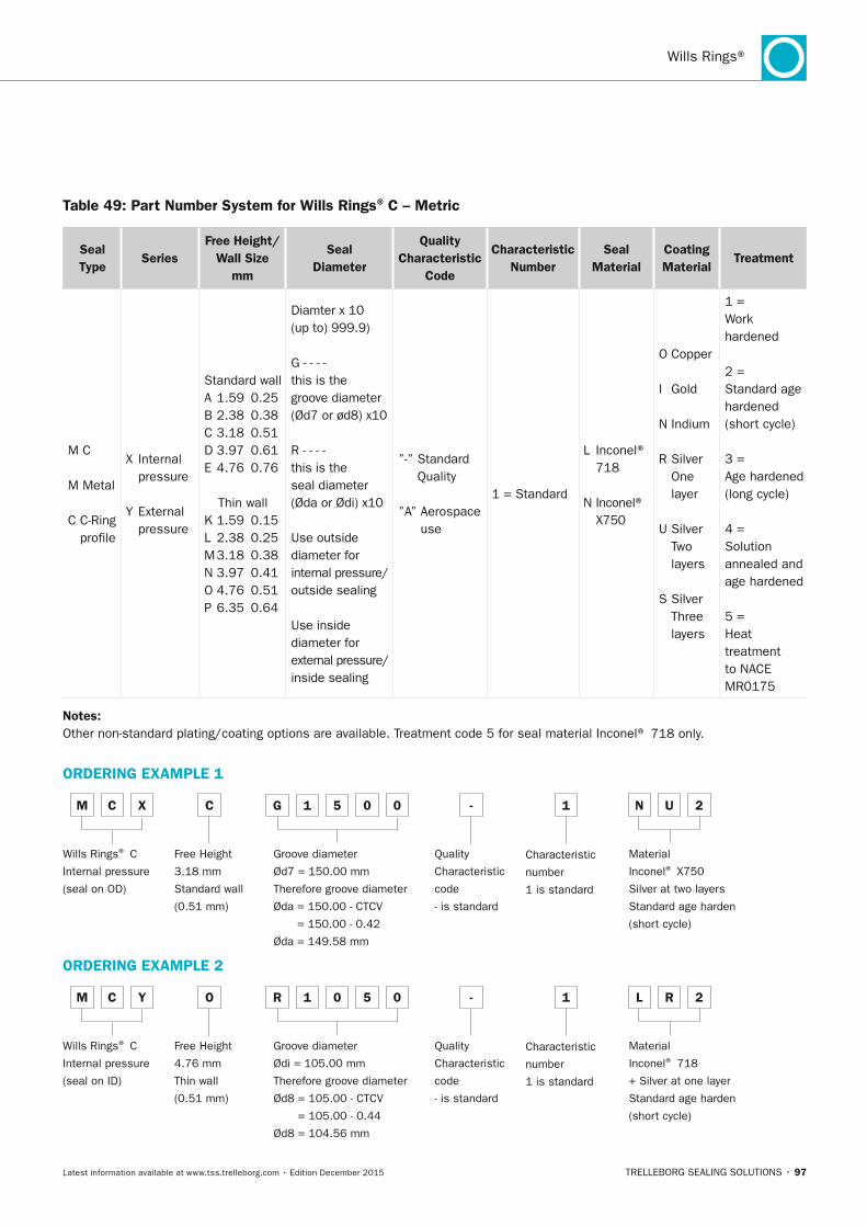
TRELLEBORG SEALING SOLUTIONS • 97Latest information available at www.tss.trelleborg.com • Edition December 2015
Wills Rings®
Table 49: Part number System for Wills Rings® C – Metric
Seal Type
SeriesFree Height/
Wall Size mm
Seal Diameter
Quality Characteristic
Code
Characteristic number
Seal Material
Coating Material
Treatment
M C
M Metal
C C-Ring profile
X Internal pressure
Y External pressure
Standard wallA 1.59 0.25B 2.38 0.38C 3.18 0.51D 3.97 0.61E 4.76 0.76
Thin wallK 1.59 0.15L 2.38 0.25M 3.18 0.38N 3.97 0.41O 4.76 0.51P 6.35 0.64
Diamter x 10 (up to) 999.9)
G - - - - this is the groove diameter (Ød7 or ød8) x10
R - - - - this is the seal diameter (Øda or Ødi) x10
Use outside diameter for internal pressure/ outside sealing
Use inside diameter for external pressure/ inside sealing
”-” Standard Quality
”A” Aerospace use
1 = Standard
L Inconel® 718
N Inconel® X750
O Copper
I Gold
N Indium
R Silver One layer
U Silver Two layers
S Silver Three layers
1 = Work hardened
2 = Standard age hardened (short cycle)
3 = Age hardened (long cycle)
4 = Solution annealed and age hardened
5 = Heat treatment to NACE MR0175
notes: Other non-standard plating/coating options are available. Treatment code 5 for seal material Inconel® 718 only.
ORDERInG ExAMPLE 1
M C x C G 1 5 0 0 - 1 n U
Wills Rings® C
Internal pressure
(seal on OD)
Free Height
3.18 mm
Standard wall
(0.51 mm)
Groove diameter
Ød7 = 150.00 mm
Therefore groove diameter
Øda = 150.00 - CTCV
= 150.00 - 0.42
Øda = 149.58 mm
Quality
Characteristic
code
- is standard
Characteristic
number
1 is standard
Material
Inconel® X750
Silver at two layers
Standard age harden
(short cycle)
2
ORDERInG ExAMPLE 2
M C y O R 1 0 5 0 - 1 L R
Wills Rings® C
Internal pressure
(seal on ID)
Free Height
4.76 mm
Thin wall
(0.51 mm)
Groove diameter
Ødi = 105.00 mm
Therefore groove diameter
Ød8 = 105.00 - CTCV
= 105.00 - 0.44
Ød8 = 104.56 mm
Quality
Characteristic
code
- is standard
Characteristic
number
1 is standard
Material
Inconel® 718
+ Silver at one layer
Standard age harden
(short cycle)
2
FBP_neues_Layout_2015.indb 97 17.10.2016 13:35:57
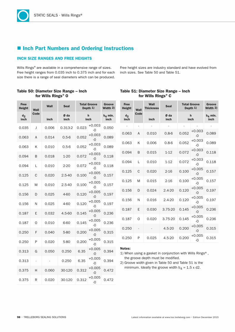
98 • TRELLEBORG SEALING SOLUTIONS Latest information available at www.tss.trelleborg.com • Edition December 2015
STATIC SEALS · Wills Rings®
� Inch Part numbers and Ordering Instructions
InCH SIZE RAnGES AnD FREE HEIGHTS
Wills Rings® are available in a comprehensive range of sizes. Free height ranges from 0.035 inch to 0.375 inch and for each size there is a range of seal diameters which can be produced.
Free height sizes are industry standard and have evolved from inch sizes. See Table 50 and Table 51.
Table 50: Diameter Size Range – Inch for Wills Rings® O
Free Height Wall
Code
Wall SealTotal Groove
Depth 1)Groove
Width 2)
d2 inch
inch
Ø da inch
h inch
b4 min. inch
0.035 J 0.006 0.313-2 0.023+0.003
-00.050
0.063 A 0.014 0.5-6 0.052+0.003
-00.089
0.063 K 0.010 0.5-6 0.052+0.003
-00.089
0.094 B 0.018 1-20 0.072+0.003
-00.118
0.094 L 0.010 2-20 0.072+0.003
-00.118
0.125 C 0.020 2.5-40 0.100+0.005
-00.157
0.125 M 0.010 2.5-40 0.100+0.005
-00.157
0.156 D 0.025 4-60 0.120+0.005
-00.197
0.156 N 0.025 4-60 0.120+0.005
-00.197
0.187 E 0.032 4.5-60 0.145+0.005
-00.236
0.187 O 0.010 6-60 0.145+0.005
-00.236
0.250 F 0.040 5-80 0.200+0.005
-00.315
0.250 P 0.020 5-80 0.200+0.005
-00.315
0.313 G 0.050 0.250 6.35+0.005
-00.394
0.313 - - 0.250 6.35+0.005
-00.394
0.375 H 0.060 30-120 0.312+0.005
-00.472
0.375 R 0.020 30-120 0.312+0.005
-00.472
Table 51: Diameter Size Range – Inch for Wills Rings® C
Free Height Wall
Code
Wall Thickness
SealTotal Groove
Depth 1)Groove
Width 2)
d2 inch
inch
Ø da inch
h inch
b4 min. inch
- - - - - - -
0.063 A 0.010 0.8-6 0.052+0.003
-00.089
0.063 K 0.006 0.8-6 0.052+0.003
-00.089
0.094 B 0.015 1-12 0.072+0.003
-00.118
0.094 L 0.010 1-12 0.072+0.003
-00.118
0.125 C 0.020 2-16 0.100+0.005
-00.157
0.125 M 0.015 2-16 0.100+0.005
-00.157
0.156 D 0.024 2.4-20 0.120+0.005
-00.197
0.156 N 0.016 2.4-20 0.120+0.005
-00.197
0.187 E 0.030 3.75-20 0.145+0.005
-00.236
0.187 O 0.020 3.75-20 0.145+0.005
-00.236
0.250 - - 4.5-20 0.200+0.005
-00.315
0.250 P 0.025 4.5-20 0.200+0.005
-00.315
notes: 1) When using a gasket in conjunction with Wills Rings®,
the groove depth must be modified.2) Groove width given in Table 50 and Table 51 is the
minimum. Ideally the groove width b4 = 1.5 x d2.
FBP_neues_Layout_2015.indb 98 17.10.2016 13:35:58
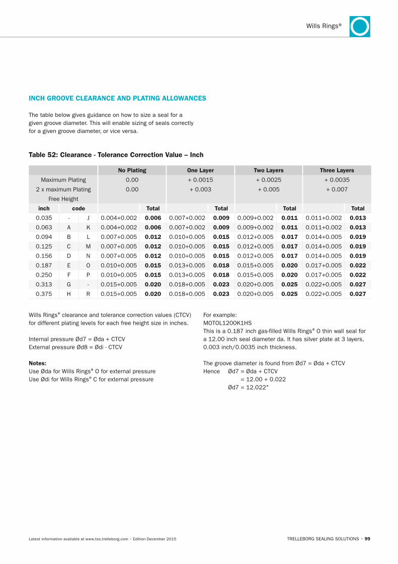
TRELLEBORG SEALING SOLUTIONS • 99Latest information available at www.tss.trelleborg.com • Edition December 2015
Wills Rings®
InCH GROOVE CLEARAnCE AnD PLATInG ALLOWAnCES
Wills Rings® clearance and tolerance correction values (CTCV) for different plating levels for each free height size in inches.
Internal pressure Ød7 = Øda + CTCVExternal pressure Ød8 = Ødi - CTCV
notes:Use Øda for Wills Rings® O for external pressureUse Ødi for Wills Rings® C for external pressure
For example:MOTOL1200K1HSThis is a 0.187 inch gas-filled Wills Rings® O thin wall seal for a 12.00 inch seal diameter da. It has silver plate at 3 layers, 0.003 inch/0.0035 inch thickness.
The groove diameter is found from Ød7 = Øda + CTCVHence Ød7 = Øda + CTCV
= 12.00 + 0.022 Ød7 = 12.022"
The table below gives guidance on how to size a seal for a given groove diameter. This will enable sizing of seals correctly for a given groove diameter, or vice versa.
Table 52: Clearance - Tolerance Correction Value – Inch
no Plating One Layer Two Layers Three Layers
Maximum Plating 0.00 + 0.0015 + 0.0025 + 0.0035
2 x maximum Plating 0.00 + 0.003 + 0.005 + 0.007
Free Height
inch code Total Total Total Total
0.035 - J 0.004+0.002 0.006 0.007+0.002 0.009 0.009+0.002 0.011 0.011+0.002 0.013
0.063 A K 0.004+0.002 0.006 0.007+0.002 0.009 0.009+0.002 0.011 0.011+0.002 0.013
0.094 B L 0.007+0.005 0.012 0.010+0.005 0.015 0.012+0.005 0.017 0.014+0.005 0.019
0.125 C M 0.007+0.005 0.012 0.010+0.005 0.015 0.012+0.005 0.017 0.014+0.005 0.019
0.156 D N 0.007+0.005 0.012 0.010+0.005 0.015 0.012+0.005 0.017 0.014+0.005 0.019
0.187 E O 0.010+0.005 0.015 0.013+0.005 0.018 0.015+0.005 0.020 0.017+0.005 0.022
0.250 F P 0.010+0.005 0.015 0.013+0.005 0.018 0.015+0.005 0.020 0.017+0.005 0.022
0.313 G - 0.015+0.005 0.020 0.018+0.005 0.023 0.020+0.005 0.025 0.022+0.005 0.027
0.375 H R 0.015+0.005 0.020 0.018+0.005 0.023 0.020+0.005 0.025 0.022+0.005 0.027
FBP_neues_Layout_2015.indb 99 17.10.2016 13:35:58
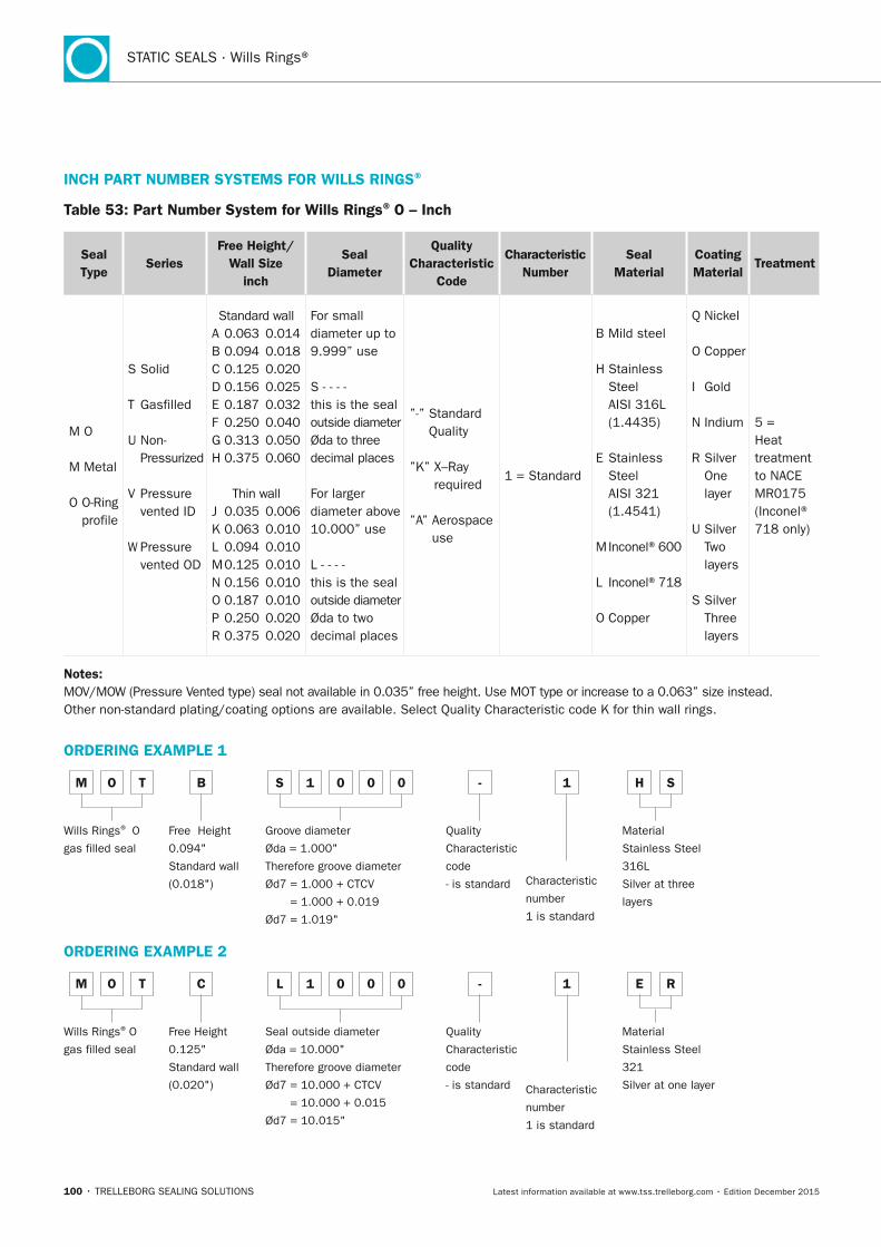
100 • TRELLEBORG SEALING SOLUTIONS Latest information available at www.tss.trelleborg.com • Edition December 2015
STATIC SEALS · Wills Rings®
InCH PART nUMBER SySTEMS FOR WILLS RInGS®
Table 53: Part number System for Wills Rings® O – Inch
Seal Type
SeriesFree Height/
Wall Size inch
Seal Diameter
Quality Characteristic
Code
Characteristic number
Seal Material
Coating Material
Treatment
M O
M Metal
O O-Ring profile
S Solid
T Gasfilled
U Non- Pressurized
V Pressure vented ID
W Pressure vented OD
Standard wallA 0.063 0.014B 0.094 0.018C 0.125 0.020D 0.156 0.025E 0.187 0.032F 0.250 0.040G 0.313 0.050H 0.375 0.060
Thin wallJ 0.035 0.006K 0.063 0.010L 0.094 0.010M 0.125 0.010N 0.156 0.010O 0.187 0.010P 0.250 0.020R 0.375 0.020
For small diameter up to 9.999” use
S - - - - this is the sealoutside diameter Øda to three decimal places
For larger diameter above 10.000” use
L - - - - this is the seal outside diameter Øda to two decimal places
”-” Standard Quality
”K” X–Ray required
”A” Aerospace use
1 = Standard
B Mild steel
H Stainless Steel AISI 316L (1.4435)
E Stainless Steel AISI 321 (1.4541)
M Inconel®600
L Inconel®718
O Copper
Q Nickel
O Copper
I Gold
N Indium
R Silver One layer
U Silver Two layers
S Silver Three layers
5 = Heat treatment to NACE MR0175 (Inconel® 718 only)
notes: MOV/MOW (Pressure Vented type) seal not available in 0.035” free height. Use MOT type or increase to a 0.063” size instead. Other non-standard plating/coating options are available. Select Quality Characteristic code K for thin wall rings.
ORDERInG ExAMPLE 1
M O T B S 1 0 0 0 - 1 H S
Wills Rings® O
gas filled seal
Free Height
0.094"
Standard wall
(0.018")
Groove diameter
Øda = 1.000"
Therefore groove diameter
Ød7 = 1.000 + CTCV
= 1.000 + 0.019
Ød7 = 1.019"
Quality
Characteristic
code
- is standard Characteristic
number
1 is standard
Material
Stainless Steel
316L
Silver at three
layers
ORDERInG ExAMPLE 2
M O T C L 1 0 0 0 - 1 E R
Wills Rings® O
gas filled seal
Free Height
0.125"
Standard wall
(0.020")
Seal outside diameter
Øda = 10.000"
Therefore groove diameter
Ød7 = 10.000 + CTCV
= 10.000 + 0.015
Ød7 = 10.015"
Quality
Characteristic
code
- is standard Characteristic
number
1 is standard
Material
Stainless Steel
321
Silver at one layer
FBP_neues_Layout_2015.indb 100 17.10.2016 13:35:58
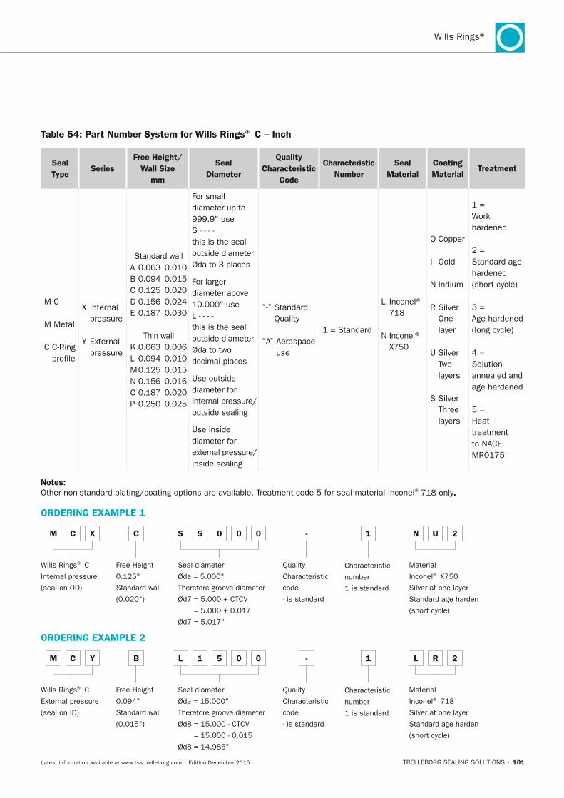
TRELLEBORG SEALING SOLUTIONS • 101Latest information available at www.tss.trelleborg.com • Edition December 2015
Wills Rings®
Table 54: Part number System for Wills Rings® C – Inch
Seal Type
SeriesFree Height/
Wall Size mm
Seal Diameter
Quality Characteristic
Code
Characteristic number
Seal Material
Coating Material
Treatment
M C
M Metal
C C-Ring profile
X Internal pressure
Y External pressure
Standard wallA 0.063 0.010B 0.094 0.015C 0.125 0.020D 0.156 0.024E 0.187 0.030
Thin wallK 0.063 0.006L 0.094 0.010M 0.125 0.015N 0.156 0.016O 0.187 0.020P 0.250 0.025
For small diameter up to 999.9" use S - - - - this is the seal outside diameter Øda to 3 places For larger diameter above 10.000" useL - - - - this is the seal outside diameter Øda to two decimal places Use outside diameter for internal pressure/ outside sealing Use inside diameter for external pressure/ inside sealing
”-” Standard Quality
”A” Aerospace use
1 = Standard
L Inconel® 718
N Inconel® X750
O Copper
I Gold
N Indium
R Silver One layer
U Silver Two layers
S Silver Three layers
1 = Work hardened
2 = Standard age hardened (short cycle)
3 = Age hardened (long cycle)
4 = Solution annealed and age hardened
5 = Heat treatment to NACE MR0175
notes: Other non-standard plating/coating options are available. Treatment code 5 for seal material Inconel® 718 only.
ORDERInG ExAMPLE 1
M C x C S 5 0 0 0 - 1 n U
Wills Rings® C
Internal pressure
(seal on OD)
Free Height
0.125"
Standard wall
(0.020")
Seal diameter
Øda = 5.000"
Therefore groove diameter
Ød7 = 5.000 + CTCV
= 5.000 + 0.017
Ød7 = 5.017"
Quality
Characteristic
code
- is standard
Characteristic
number
1 is standard
Material
Inconel® X750
Silver at one layer
Standard age harden
(short cycle)
2
ORDERInG ExAMPLE 2
M C y B L 1 5 0 0 - 1 L R
Wills Rings® C
External pressure
(seal on ID)
Free Height
0.094"
Standard wall
(0.015")
Seal diameter
Øda = 15.000"
Therefore groove diameter
Ød8 = 15.000 - CTCV
= 15.000 - 0.015
Ød8 = 14.985"
Quality
Characteristic
code
- is standard
Characteristic
number
1 is standard
Material
Inconel® 718
Silver at one layer
Standard age harden
(short cycle)
2
FBP_neues_Layout_2015.indb 101 17.10.2016 13:35:59
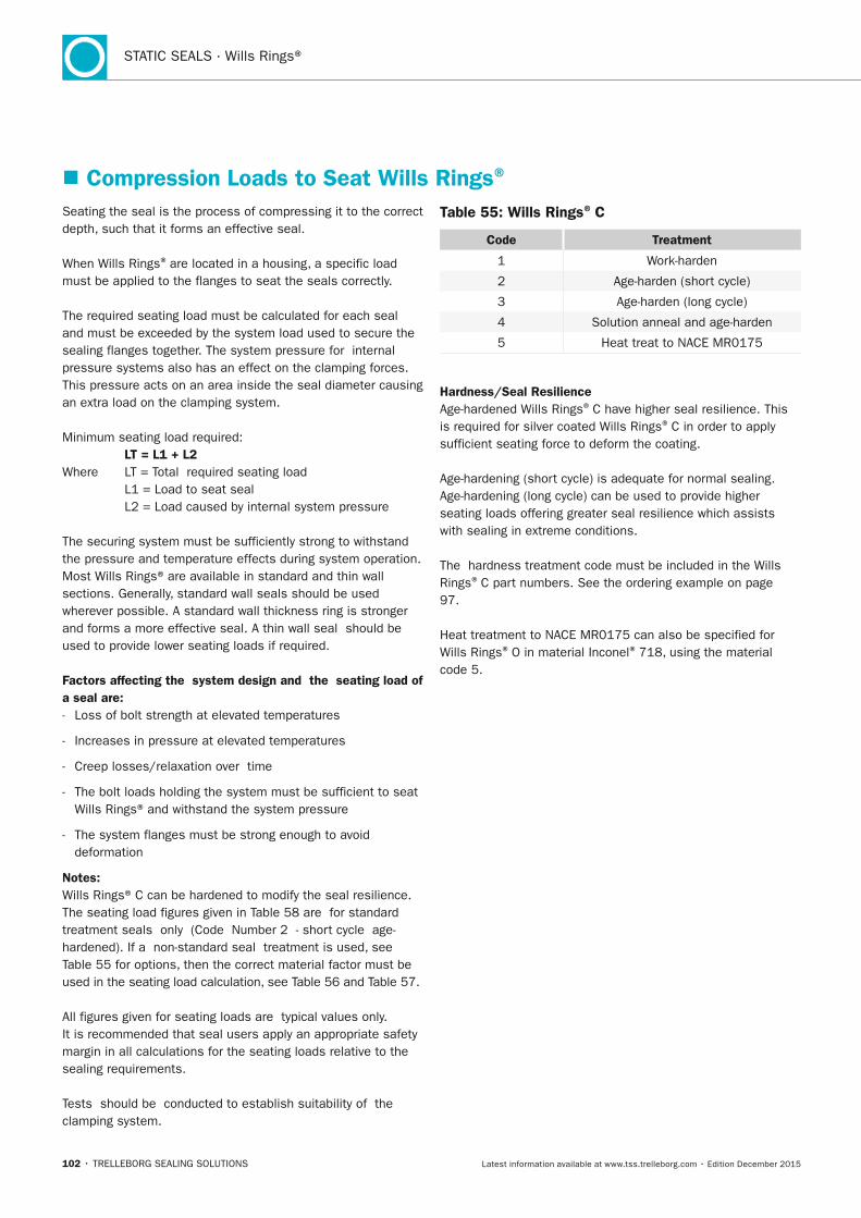
102 • TRELLEBORG SEALING SOLUTIONS Latest information available at www.tss.trelleborg.com • Edition December 2015
STATIC SEALS · Wills Rings®
� Compression Loads to Seat Wills Rings®
Seating the seal is the process of compressing it to the correct depth, such that it forms an effective seal.
When Wills Rings® are located in a housing, a specific load must be applied to the flanges to seat the seals correctly.
The required seating load must be calculated for each seal and must be exceeded by the system load used to secure the sealing flanges together. The system pressure for internal pressure systems also has an effect on the clamping forces. This pressure acts on an area inside the seal diameter causing an extra load on the clamping system.
Minimum seating load required: LT = L1 + L2Where LT = Total required seating load L1 = Load to seat seal L2 = Load caused by internal system pressure
The securing system must be sufficiently strong to withstand the pressure and temperature effects during system operation. Most Wills Rings® are available in standard and thin wall sections. Generally, standard wall seals should be used wherever possible. A standard wall thickness ring is stronger and forms a more effective seal. A thin wall seal should be used to provide lower seating loads if required.
Factors affecting the system design and the seating load of a seal are: - Loss of bolt strength at elevated temperatures
- Increases in pressure at elevated temperatures
- Creep losses/relaxation over time
- The bolt loads holding the system must be sufficient to seat Wills Rings® and withstand the system pressure
- The system flanges must be strong enough to avoid deformation
notes:Wills Rings® C can be hardened to modify the seal resilience. The seating load figures given in Table 58 are for standard treatment seals only (Code Number 2 - short cycle age- hardened). If a non-standard seal treatment is used, see Table 55 for options, then the correct material factor must be used in the seating load calculation, see Table 56 and Table 57.
All figures given for seating loads are typical values only.It is recommended that seal users apply an appropriate safety margin in all calculations for the seating loads relative to the sealing requirements.
Tests should be conducted to establish suitability of the clamping system.
Table 55: Wills Rings® C
Code Treatment
1 Work-harden
2 Age-harden (short cycle)
3 Age-harden (long cycle)
4 Solution anneal and age-harden
5 Heat treat to NACE MR0175
Hardness/Seal ResilienceAge-hardened Wills Rings® C have higher seal resilience. This is required for silver coated Wills Rings® C in order to apply sufficient seating force to deform the coating.
Age-hardening (short cycle) is adequate for normal sealing. Age-hardening (long cycle) can be used to provide higher seating loads offering greater seal resilience which assists with sealing in extreme conditions.
The hardness treatment code must be included in the Wills Rings® C part numbers. See the ordering example on page 97.
Heat treatment to NACE MR0175 can also be specified for Wills Rings® O in material Inconel® 718, using the material code 5.
FBP_neues_Layout_2015.indb 102 17.10.2016 13:35:59
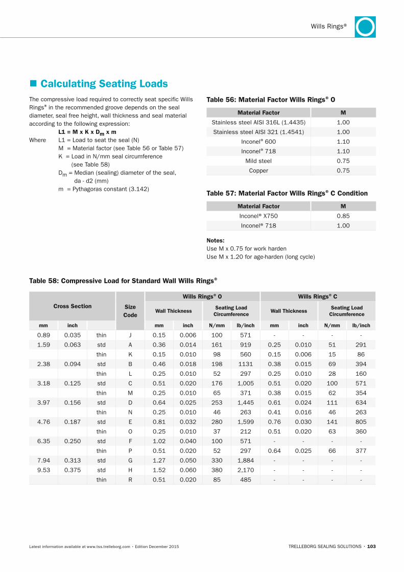
TRELLEBORG SEALING SOLUTIONS • 103Latest information available at www.tss.trelleborg.com • Edition December 2015
Wills Rings®
� Calculating Seating Loads
Table 58: Compressive Load for Standard Wall Wills Rings®
Cross Section Size Code
Wills Rings® O Wills Rings® C
Wall Thickness Seating Load
CircumferenceWall Thickness
Seating Load Circumference
mm inch mm inch n/mm lb/inch mm inch n/mm lb/inch
0.89 0.035 thin J 0.15 0.006 100 571 - - - -
1.59 0.063 std A 0.36 0.014 161 919 0.25 0.010 51 291
thin K 0.15 0.010 98 560 0.15 0.006 15 86
2.38 0.094 std B 0.46 0.018 198 1131 0.38 0.015 69 394
thin L 0.25 0.010 52 297 0.25 0.010 28 160
3.18 0.125 std C 0.51 0.020 176 1,005 0.51 0.020 100 571
thin M 0.25 0.010 65 371 0.38 0.015 62 354
3.97 0.156 std D 0.64 0.025 253 1,445 0.61 0.024 111 634
thin N 0.25 0.010 46 263 0.41 0.016 46 263
4.76 0.187 std E 0.81 0.032 280 1,599 0.76 0.030 141 805
thin O 0.25 0.010 37 212 0.51 0.020 63 360
6.35 0.250 std F 1.02 0.040 100 571 - - - -
thin P 0.51 0.020 52 297 0.64 0.025 66 377
7.94 0.313 std G 1.27 0.050 330 1,884 - - - -
9.53 0.375 std H 1.52 0.060 380 2,170 - - - -
thin R 0.51 0.020 85 485 - - - -
The compressive load required to correctly seat specific Wills Rings® in the recommended groove depends on the seal diameter, seal free height, wall thickness and seal material according to the following expression: L1 = M x K x Dm x mWhere L1 = Load to seat the seal (N) M = Material factor (see Table 56 or Table 57) K = Load in N/mm seal circumference
(see Table 58) Dm = Median (sealing) diameter of the seal,
da - d2 (mm) m = Pythagoras constant (3.142)
Table 56: Material Factor Wills Rings® O
Material Factor M
Stainless steel AISI 316L (1.4435) 1.00
Stainless steel AISI 321 (1.4541) 1.00
Inconel® 600 1.10
Inconel® 718 1.10
Mild steel 0.75
Copper 0.75
Table 57: Material Factor Wills Rings® C Condition
Material Factor M
Inconel® X750 0.85
Inconel® 718 1.00
notes:Use M x 0.75 for work harden Use M x 1.20 for age-harden (long cycle)
FBP_neues_Layout_2015.indb 103 17.10.2016 13:35:59
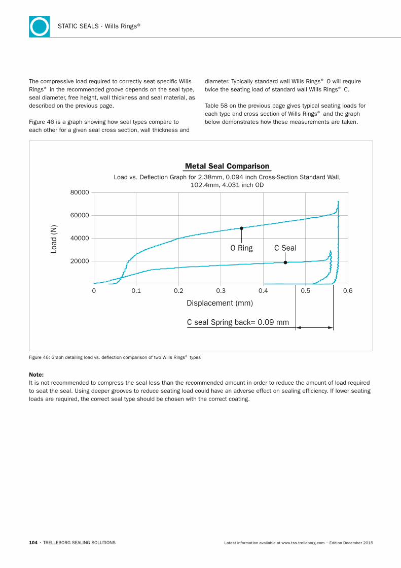
104 • TRELLEBORG SEALING SOLUTIONS Latest information available at www.tss.trelleborg.com • Edition December 2015
STATIC SEALS · Wills Rings®
Figure 46: Graph detailing load vs. deflection comparison of two Wills Rings® types
note:It is not recommended to compress the seal less than the recommended amount in order to reduce the amount of load required to seat the seal. Using deeper grooves to reduce seating load could have an adverse effect on sealing efficiency. If lower seating loads are required, the correct seal type should be chosen with the correct coating.
The compressive load required to correctly seat specific Wills Rings® in the recommended groove depends on the seal type, seal diameter, free height, wall thickness and seal material, as described on the previous page.
Figure 46 is a graph showing how seal types compare to each other for a given seal cross section, wall thickness and
diameter. Typically standard wall Wills Rings® O will require twice the seating load of standard wall Wills Rings® C.
Table 58 on the previous page gives typical seating loads for each type and cross section of Wills Rings® and the graph below demonstrates how these measurements are taken.
0 0.20.1 0.3 0.4 0.5 0.6
Load
(N)
Displacement (mm)
20000
40000
60000
80000
Metal Seal ComparisonLoad vs. De�ection Graph for 2.38mm, 0.094 inch Cross-Section Standard Wall,
102.4mm, 4.031 inch OD
C seal Spring back= 0.09 mm
O Ring C Seal
FBP_neues_Layout_2015.indb 104 17.10.2016 13:36:00
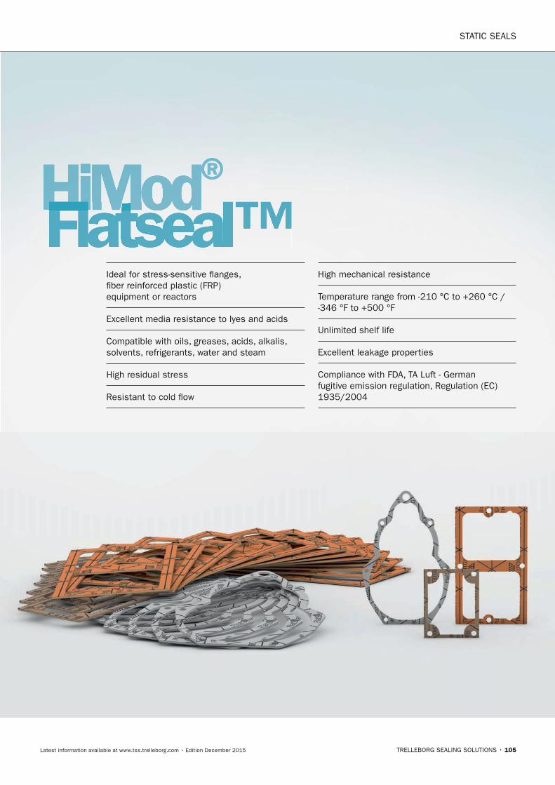
STATIC SEALS
TRELLEBORG SEALING SOLUTIONS • 105Latest information available at www.tss.trelleborg.com • Edition December 2015
HiMod®HiMod®HiModFlatseal™HiModFlatseal™HiModIdeal for stress-sensitive flanges, fiber reinforced plastic (FRP) equipment or reactors
Excellent media resistance to lyes and acids
Compatible with oils, greases, acids, alkalis, solvents, refrigerants, water and steam
High residual stress
Resistant to cold flow
High mechanical resistance
Temperature range from -210 °C to +260 °C / -346 °F to +500 °F
Unlimited shelf life
Excellent leakage properties
Compliance with FDA, TA Luft - German fugitive emission regulation, Regulation (EC) 1935/2004
FBP_neues_Layout_2015.indb 105 17.10.2016 13:36:05

STATIC SEALS · HiMod® Flatseal™
106 • TRELLEBORG SEALING SOLUTIONS Latest information available at www.tss.trelleborg.com • Edition December 2015
FBP_neues_Layout_2015.indb 106 17.10.2016 13:36:05
HiMod® Flatseal™
TRELLEBORG SEALING SOLUTIONS • 107Latest information available at www.tss.trelleborg.com • Edition December 2015
� HiMod® Flatseal™
DESCRIPTIOn
The HiMod® Flatseal™ range consists of flat gaskets made from the proprietary HiMod® material, offering superior performance compared with conventional flat gaskets. They are compliant with virtually all relevant standards.
The product is die-cut and is available in any standard or customer specified dimension. The HiMod® Flatseal™ products are manufactured in facilities that comply with ISO/TS 16949 and ISO 14001, meaning complete transparency in all areas of production and a high degree of reliability and security for customers.
A number of compounds have been specially developed for the demanding applications of the food, beverage and pharmaceutical market.
For more detailed information on specific HiMod® Flatseal™ products, see the relevant flyer available from tss.trelleborg.com or contact your local Trelleborg Sealing Solutions marketing company.
� HiMod® FlatSeal™ 10
DESCRIPTIOn
The balanced raw material combination, consisting of high-quality aramide fibers, special fillers and nitrile butadiene rubber (NBR) makes this product suitable for a wide variety of standard applications ideal for use in average temperatures and pressures.
In addition to the benefits for all of the HiMod® Flatseal™ range, HiMod® Flatseal™ 10 also offers:
- Good media resistance and stress relaxation
- Excellent performance in average temperatures and pressures
- Leakage less than the limits specified in DIN 3535-6
- Anti-stick coating on one side
- Compliances in accordance with:
• DVGW - German association for gas and water
• KTW - German recommendation for use with drinking water
• W270 - Microbiological suitability for use with drinking water
• WRAS - Water Research Advisory Scheme
• 1935/2004 - EU regulation on materials and articles intended to come into contact with food
FBP_neues_Layout_2015.indb 107 17.10.2016 13:36:06
STATIC SEALS · HiMod® Flatseal™
108 • TRELLEBORG SEALING SOLUTIONS Latest information available at www.tss.trelleborg.com • Edition December 2015
� HiMod® FlatSeal™ 17
DESCRIPTIOn
HiMod® FlatSeal™ 17 is based on an innovative blend of high-quality aramid fibers, special functional fillers and nitrile butadiene rubber (NBR). The new material combines the characteristics of fiber gaskets with the positive properties of elastomers, thus making it possible to produce a unique performance profile.
In addition to the benefits for all of the HiMod® Flatseal™ range, HiMod Flatseal™ 17 also offers:
- Excellent adaptability to unevenness at minimum surface pressure levels
- Very low leakage levels even when surface pressure is extremely low
- Stable long-term properties at operational temperatures
- Good resistance to media and aging
- Smooth processability and safe handling even with complex gasket outlines
- Compliances in accordance with:
• DVGW - German association for gas and water
• FDA 177.2600 Rubber - US Food and Drug Administration
• 1935/2004 - EU regulation on materials and articles intended to come into contact with food
� HiMod® FlatSeal™ 20
DESCRIPTIOn
HiMod® Flatseal™ 20 is a new and more efficient generation of graphite gaskets reinforced with aramid fibres. A considerable reduction in leakage in combination with excellent residual stress and chemical resistance levels are achieved thanks to careful graphite structural design and ingenious process engineering.
In addition to the benefits for all of the HiMod® Flatseal™ range, HiMod Flatseal™ 20 also offers:
- Very high long-term pressure resistance
- Compatibility with a high proportion of media commonly used in the food, beverage and pharmaceutical industries including oils,greases, acids, alkalis, solvents, refrigerants, water and steam
- Good temperature resistance
- Extended life, reducing intervals for planned maintenance
- Compensation for flange unevenness and roughness
- Performance while being environmentally-friendly and solvent-free
- Leakage less than limits specified in DIN 3535-6
- Blowout resistance
- Compliance to fugitive emissions standards
- Compliances in accordance with:
• BAM - German Federal Institute for Materials Research and Testing
• DVGW - German association for gas and water
• KTW - German recommendation for use with drinking water
• W270 - Microbiological suitability for use with drinking water
• WRAS - Water Research Advisory Scheme
• TA-Luft - German fugitive emission regulation TA Luft [leakage rate < 10-4 mbar•l/(s•m)]
• 1935/2004 - EU regulation on materials and articles intended to come into contact with food
FBP_neues_Layout_2015.indb 108 17.10.2016 13:36:06
HiMod® Flatseal™
TRELLEBORG SEALING SOLUTIONS • 109Latest information available at www.tss.trelleborg.com • Edition December 2015
� HiMod® FlatSeal™ 41
DESCRIPTIOn
A modified PTFE with mineral filler. With an extremely high compressibility, the HiMod® FlatSeal™ 41 is suitable for use in stress-sensitive flanges, such as glass, ceramic and fiber-reinforced plastic (FRP) flanges. It has been shown to reduce downtime and increase machine reliability and availability.
In addition to the benefits for all of the HiMod® FlatSeal™ range, HiMod® FlatSeal™ 41 also offers:
- Excellent anti-stick properties
- Compensation for minor damage or unevenness in the flange surface
- High compressibility
- Excellent media resistance to most lyes and acids throughout the pH range (pH levels 0-14)
- Compatibility with oils, greases, acids, alkalis, solvents, refrigerants, water and steam
- Resistance to cold flow
- Wide temperature range performance from -210 °C to +260 °C / -346 °F to +500 °F
- Unlimited shelf life
- Excellent leakage properties
- Compliances in accordance with:
• TA-Luft - German fugitive emission regulation TA Luft [leakage rate < 10-4 mbar•l/(s•m)]
• FDA 177.1550 Perfluorocarbon - - US Food and Drug Administration
• 1935/2004 EU regulation on materials and articles intended to come into contact with food
� HiMod® FlatSeal™ 43
DESCRIPTIOn
A modified PTFE with silica, HiMod® FlatSeal™ 43 offers a balance between chemical resistance and reduced creep properties.
In addition to the benefits for all of the HiMod® FlatSeal™ range, HiMod® FlatSeal™ 43 also offers:
- Excellent media resistance to most lyes and acids throughout the pH range (pH levels 0-14)
- Concentrated acid resistance
- Compatibility with oils, greases, acids, alkalis, solvents, refrigerants, water and steam
- High residual stress
- Resistance to cold flow
- High mechanical resistance at high pressure (vacuum to 8.3 MPa / 1,203 psi)
- Wide temperature range performance from -210 °C to +260 °C / -346 °F to +500 °F
- Unlimited shelf life
- Excellent leakage properties
- Compliances in accordance with:
• DVGW - German association for gas and water
• BAM - German Federal Institute for Materials Research and Testing
• TA-Luft - German fugitive emission regulation TA Luft [leakage rate < 10-4 mbar•l/(s•m)]
• FDA 177.1550 Perfluorocarbon - US Food and Drug Administration
• 1935/2004 - EU regulation on materials and articles intended to come into contact with food
FBP_neues_Layout_2015.indb 109 17.10.2016 13:36:06
STATIC SEALS · HiMod® Flatseal™
110 • TRELLEBORG SEALING SOLUTIONS Latest information available at www.tss.trelleborg.com • Edition December 2015
� HiMod® FlatSeal™ 45
DESCRIPTIOn
100% multi-directional expanded PTFE. Offering superior performance compared to conventional polytetrafluoroethylene (PTFE) flat gaskets with nearly universal chemical resistance, resistance to creep, cold flow and pressure. These properties make this the perfect material for glass-lined flanges, FRP equipment or in process-industry reactors for the food, beverage and pharmaceutical market.
In addition to the benefits for all of the HiMod® FlatSeal™ range, HiMod® FlatSeal™ 45 also offers:
- Unrivalled chemical resistance
- High resistantce to creep and cold flow
- Compensation for low bolt-forces and flange irregularities
- High mechanical resistance at high pressure (vacuum to 10 MPa / 1,450 psi)
- Wide temperature range performance from -210 °C to +260 °C / -346 °F to +500 °F
- Unlimited shelf life
- Excellent leakage properties
- Compliances in accordance with:
• BAM - German Federal Institute for Materials Research and Testing
• TA-Luft - German fugitive emission regulation TA Luft [leakage rate < 10-4 mbar•l/(s•m)]
• FDA 177.1550 Perfluorocarbon - US Food and Drug Administration
• 1935/2004 - EU regulation on materials and articles intended to come into contact with food
FBP_neues_Layout_2015.indb 110 17.10.2016 13:36:06
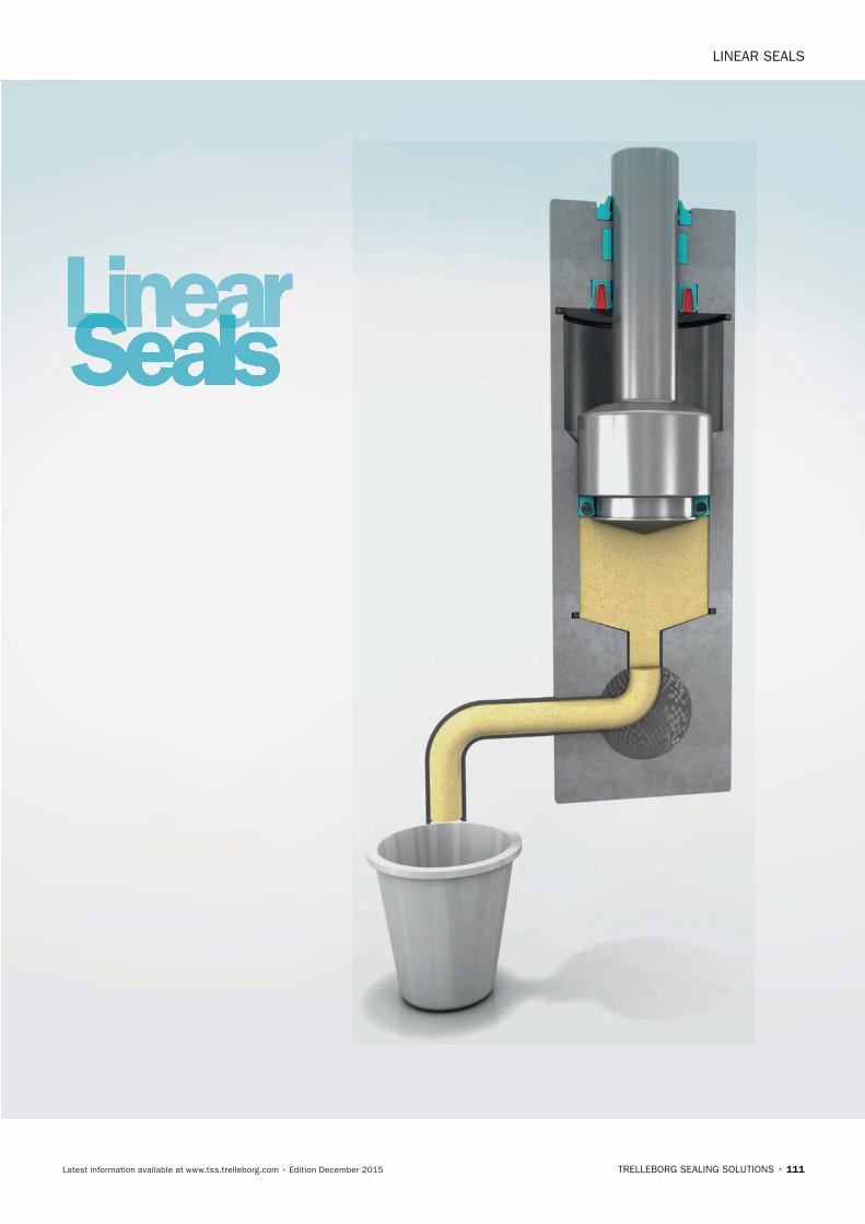
Linear SeaLS
TRELLEBORG SEALING SOLUTIONS • 111Latest information available at www.tss.trelleborg.com • Edition December 2015
LinearSealsLinearSealsLinear
FBP_neues_Layout_2015.indb 111 17.10.2016 13:36:11

112 • TRELLEBORG SEALING SOLUTIONS Latest information available at www.tss.trelleborg.com • Edition December 2015
LINEAR SEALS
FBP_neues_Layout_2015.indb 112 17.10.2016 13:36:11
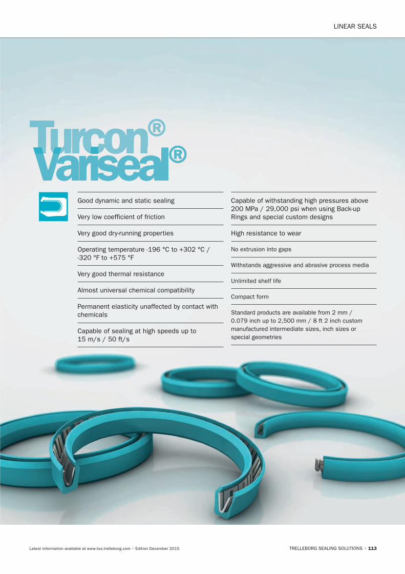
LINEAR SEALS
TRELLEBORG SEALING SOLUTIONS • 113Latest information available at www.tss.trelleborg.com • Edition December 2015
Turcon®VarisealTurconVarisealTurcon ®
Good dynamic and static sealing
Very low coefficient of friction
Very good dry-running properties
Operating temperature -196 °C to +302 °C / -320 °F to +575 °F
Very good thermal resistance
Almost universal chemical compatibility
Permanent elasticity unaffected by contact with chemicals
Capable of sealing at high speeds up to 15 m/s / 50 ft/s
Capable of withstanding high pressures above 200 MPa / 29,000 psi when using Back-up Rings and special custom designs
High resistance to wear
No extrusion into gaps
Withstands aggressive and abrasive process media
Unlimited shelf life
Compact form
Standard products are available from 2 mm / 0.079 inch up to 2,500 mm / 8 ft 2 inch custom manufactured intermediate sizes, inch sizes or special geometries
FBP_neues_Layout_2015.indb 113 17.10.2016 13:36:14

LINEAR SEALS · Turcon® Variseal®
114 • TRELLEBORG SEALING SOLUTIONS Latest information available at www.tss.trelleborg.com • Edition December 2015
FBP_neues_Layout_2015.indb 114 17.10.2016 13:36:14
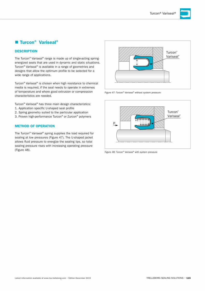
Turcon® Variseal®
TRELLEBORG SEALING SOLUTIONS • 115Latest information available at www.tss.trelleborg.com • Edition December 2015
� Turcon® Variseal®
DESCRIPTIOn
The Turcon® Variseal® range is made up of single-acting spring-energized seals that are used in dynamic and static situations. Turcon® Variseal® is available in a range of geometries and designs that allow the optimum profile to be selected for a wide range of applications.
Turcon® Variseal® is chosen when high resistance to chemical media is required, if the seal needs to operate in extremes of temperature and where good extrusion or compression characteristics are needed.
Turcon® Variseal® has three main design characteristics:1. Application specific U-shaped seal profile2. Spring geometry suited to the particular application3. Proven high-performance Turcon® or Zurcon® polymers
METHOD OF OPERATIOn
The Turcon® Variseal® spring supplies the load required for sealing at low pressures (Figure 47). The U-shaped jacket allows fluid pressure to energize the sealing lips, so total sealing pressure rises with increasing operating pressure (Figure 48).
Turcon® Variseal®
Figure 47: Turcon® Variseal® without system pressure
Turcon® Variseal®
P
Figure 48: Turcon® Variseal® with system pressure
FBP_neues_Layout_2015.indb 115 17.10.2016 13:36:15
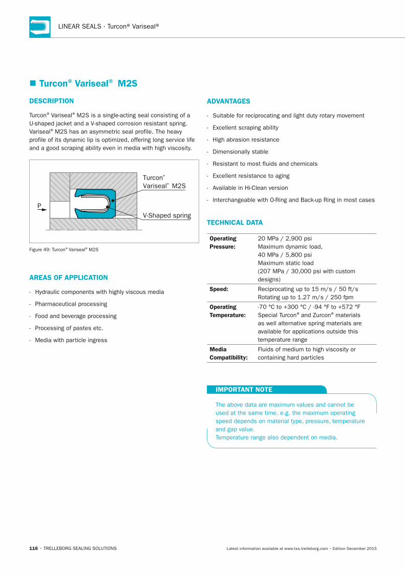
LINEAR SEALS · Turcon® Variseal®
116 • TRELLEBORG SEALING SOLUTIONS Latest information available at www.tss.trelleborg.com • Edition December 2015
� Turcon® Variseal® M2S
DESCRIPTIOn
Turcon® Variseal® M2S is a single-acting seal consisting of a U-shaped jacket and a V-shaped corrosion resistant spring. Variseal® M2S has an asymmetric seal profile. The heavy profile of its dynamic lip is optimized, offering long service life and a good scraping ability even in media with high viscosity.
Turcon® Variseal® M2S
V-Shaped springP
Figure 49: Turcon® Variseal® M2S
AREAS OF APPLICATIOn
- Hydraulic components with highly viscous media
- Pharmaceutical processing
- Food and beverage processing
- Processing of pastes etc.
- Media with particle ingress
ADVAnTAGES
- Suitable for reciprocating and light duty rotary movement
- Excellent scraping ability
- High abrasion resistance
- Dimensionally stable
- Resistant to most fluids and chemicals
- Excellent resistance to aging
- Available in Hi-Clean version
- Interchangeable with O-Ring and Back-up Ring in most cases
TECHnICAL DATA
Operating Pressure:
20 MPa / 2,900 psi Maximum dynamic load, 40 MPa / 5,800 psi Maximum static load (207 MPa / 30,000 psi with custom designs)
Speed: Reciprocating up to 15 m/s / 50 ft/s Rotating up to 1.27 m/s / 250 fpm
Operating Temperature:
-70 °C to +300 °C / -94 °F to +572 °F Special Turcon® and Zurcon® materials as well alternative spring materials are available for applications outside this temperature range
Media Compatibility:
Fluids of medium to high viscosity or containing hard particles
IMPORTAnT nOTE
The above data are maximum values and cannot be used at the same time. e.g. the maximum operating speed depends on material type, pressure, temperature and gap value. Temperature range also dependent on media.
FBP_neues_Layout_2015.indb 116 17.10.2016 13:36:15
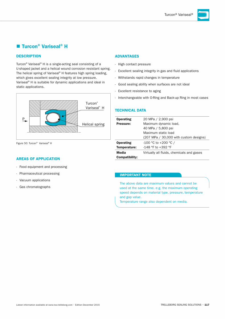
Turcon® Variseal®
TRELLEBORG SEALING SOLUTIONS • 117Latest information available at www.tss.trelleborg.com • Edition December 2015
� Turcon® Variseal® H
DESCRIPTIOn
Turcon® Variseal® H is a single-acting seal consisting of a U-shaped jacket and a helical wound corrosion resistant spring.The helical spring of Variseal® H features high spring loading, which gives excellent sealing integrity at low pressure. Variseal® H is suitable for dynamic applications and ideal in static applications.
Turcon® Variseal® H
Helical springP
Figure 50: Turcon® Variseal® H
AREAS OF APPLICATIOn
- Food equipment and processing
- Pharmaceutical processing
- Vacuum applications
- Gas chromatographs
ADVAnTAGES
- High contact pressure
- Excellent sealing integrity in gas and fluid applications
- Withstands rapid changes in temperature
- Good sealing ability when surfaces are not ideal
- Excellent resistance to aging
- Interchangeable with O-Ring and Back-up Ring in most cases
TECHnICAL DATA
Operating Pressure:
20 MPa / 2,900 psi Maximum dynamic load, 40 MPa / 5,800 psi Maximum static load (207 MPa / 30,000 with custom designs)
Operating Temperature:
-100 °C to +200 °C / -148 °F to +392 °F
Media Compatibility:
Virtually all fluids, chemicals and gases
IMPORTAnT nOTE
The above data are maximum values and cannot be used at the same time. e.g. the maximum operating speed depends on material type, pressure, temperature and gap value. Temperature range also dependent on media.
FBP_neues_Layout_2015.indb 117 17.10.2016 13:36:16
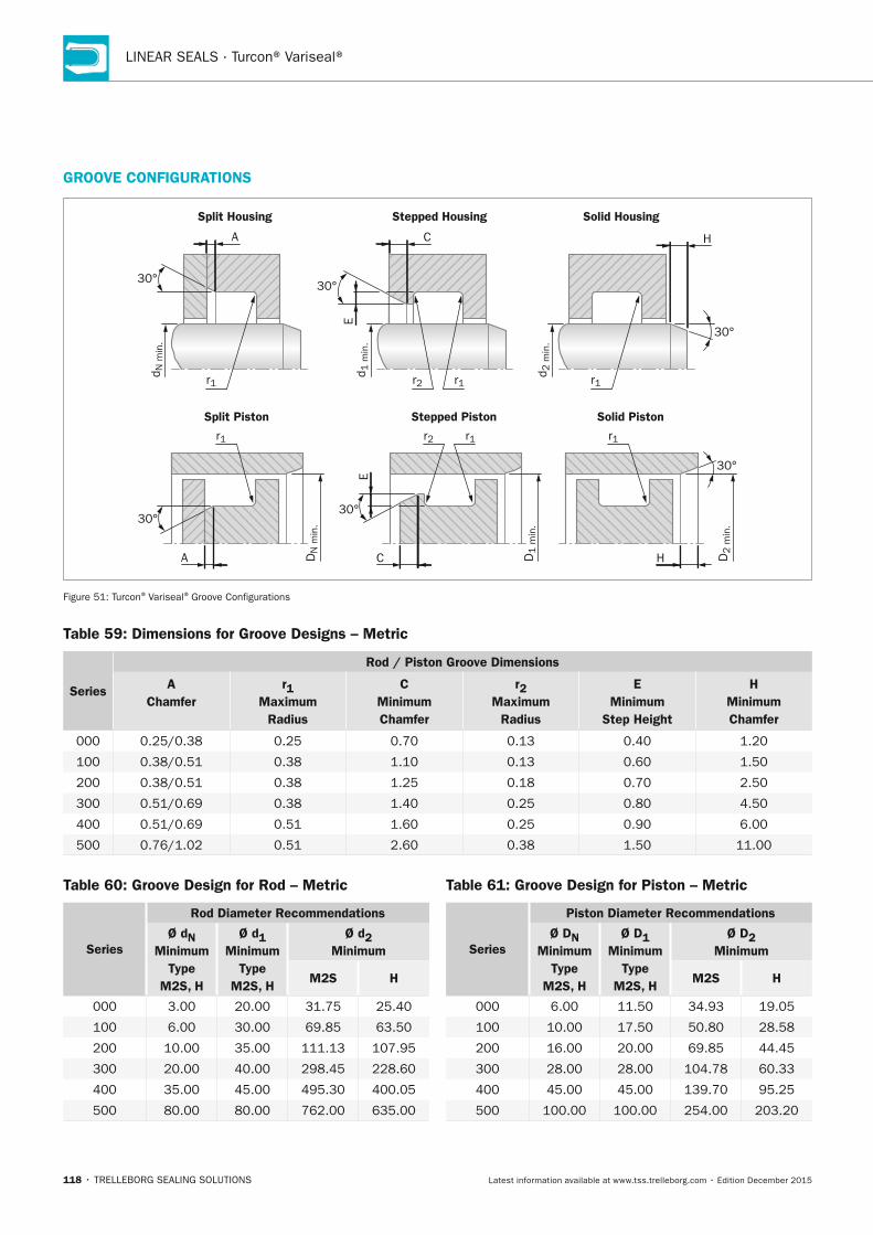
LINEAR SEALS · Turcon® Variseal®
118 • TRELLEBORG SEALING SOLUTIONS Latest information available at www.tss.trelleborg.com • Edition December 2015
GROOVE COnFIGURATIOnS
Split Housing
Split Piston Stepped Piston Solid Piston
Stepped Housing Solid Housing
r1
30°
30°
A C
A HC
d N m
in.
D1 m
in.
DN
min
.
D2 m
in.
30°
30°
30°
30°
r2
r2
r1
r1
d 1 m
in.
EE
H
d 2 m
in.
r1 r1
r1
Figure 51: Turcon® Variseal® Groove Configurations
Table 59: Dimensions for Groove Designs – Metric
Series
Rod / Piston Groove Dimensions
A Chamfer
r1 Maximum
Radius
C Minimum Chamfer
r2 Maximum
Radius
E Minimum
Step Height
H Minimum Chamfer
000 0.25/0.38 0.25 0.70 0.13 0.40 1.20
100 0.38/0.51 0.38 1.10 0.13 0.60 1.50
200 0.38/0.51 0.38 1.25 0.18 0.70 2.50
300 0.51/0.69 0.38 1.40 0.25 0.80 4.50
400 0.51/0.69 0.51 1.60 0.25 0.90 6.00
500 0.76/1.02 0.51 2.60 0.38 1.50 11.00
Table 60: Groove Design for Rod – Metric
Series
Rod Diameter Recommendations
Ø dn Minimum
Type M2S, H
Ø d1 Minimum
Type M2S, H
Ø d2 Minimum
M2S H
000 3.00 20.00 31.75 25.40
100 6.00 30.00 69.85 63.50
200 10.00 35.00 111.13 107.95
300 20.00 40.00 298.45 228.60
400 35.00 45.00 495.30 400.05
500 80.00 80.00 762.00 635.00
Table 61: Groove Design for Piston – Metric
Series
Piston Diameter Recommendations
Ø Dn Minimum
Type M2S, H
Ø D1 Minimum
Type M2S, H
Ø D2 Minimum
M2S H
000 6.00 11.50 34.93 19.05
100 10.00 17.50 50.80 28.58
200 16.00 20.00 69.85 44.45
300 28.00 28.00 104.78 60.33
400 45.00 45.00 139.70 95.25
500 100.00 100.00 254.00 203.20
FBP_neues_Layout_2015.indb 118 17.10.2016 13:36:17
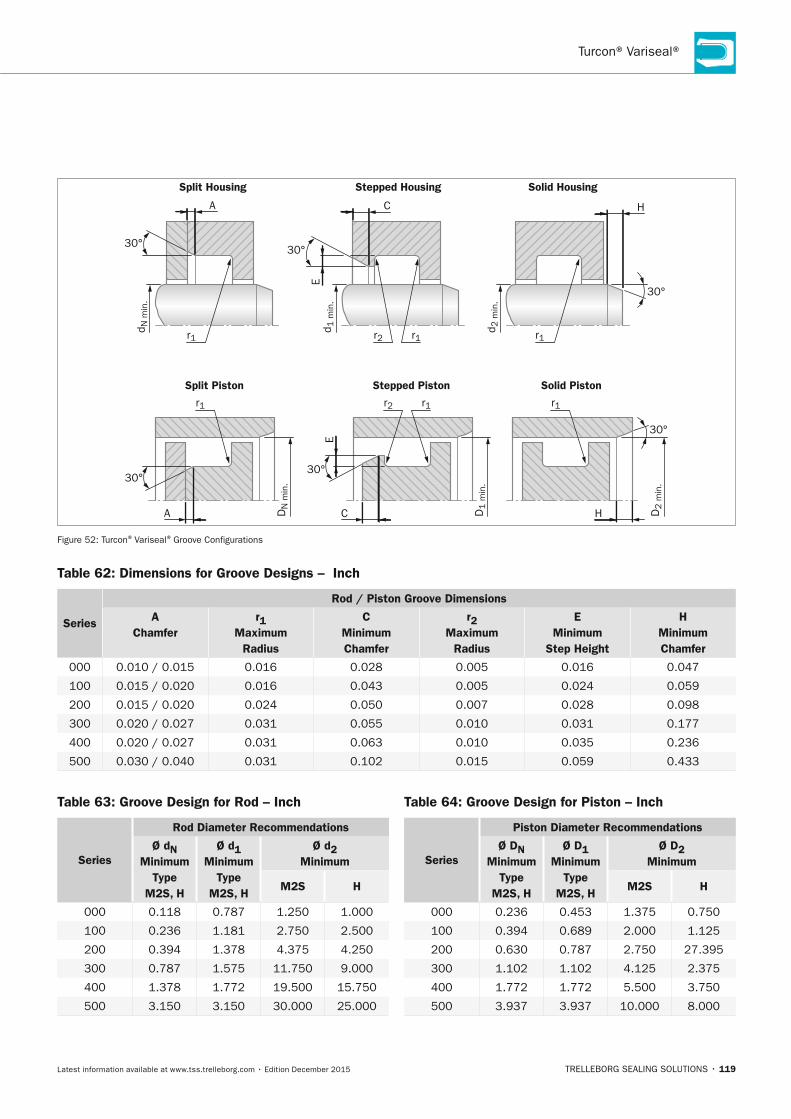
Turcon® Variseal®
TRELLEBORG SEALING SOLUTIONS • 119Latest information available at www.tss.trelleborg.com • Edition December 2015
Table 63: Groove Design for Rod – Inch
Series
Rod Diameter Recommendations
Ø dn Minimum
Type M2S, H
Ø d1 Minimum
Type M2S, H
Ø d2 Minimum
M2S H
000 0.118 0.787 1.250 1.000
100 0.236 1.181 2.750 2.500
200 0.394 1.378 4.375 4.250
300 0.787 1.575 11.750 9.000
400 1.378 1.772 19.500 15.750
500 3.150 3.150 30.000 25.000
Table 64: Groove Design for Piston – Inch
Series
Piston Diameter Recommendations
Ø Dn Minimum
Type M2S, H
Ø D1 Minimum
Type M2S, H
Ø D2 Minimum
M2S H
000 0.236 0.453 1.375 0.750
100 0.394 0.689 2.000 1.125
200 0.630 0.787 2.750 27.395
300 1.102 1.102 4.125 2.375
400 1.772 1.772 5.500 3.750
500 3.937 3.937 10.000 8.000
Split Housing
Split Piston Stepped Piston Solid Piston
Stepped Housing Solid Housing
r1
30°
30°
A C
A HC
d N m
in.
D1 m
in.
DN
min
.
D2 m
in.
30°
30°
30°
30°
r2
r2
r1
r1
d 1 m
in.
EE
H
d 2 m
in.
r1 r1
r1
Figure 52: Turcon® Variseal® Groove Configurations
Table 62: Dimensions for Groove Designs – Inch
Series
Rod / Piston Groove Dimensions
A Chamfer
r1 Maximum
Radius
C Minimum Chamfer
r2 Maximum
Radius
E Minimum
Step Height
H Minimum Chamfer
000 0.010 / 0.015 0.016 0.028 0.005 0.016 0.047
100 0.015 / 0.020 0.016 0.043 0.005 0.024 0.059
200 0.015 / 0.020 0.024 0.050 0.007 0.028 0.098
300 0.020 / 0.027 0.031 0.055 0.010 0.031 0.177
400 0.020 / 0.027 0.031 0.063 0.010 0.035 0.236
500 0.030 / 0.040 0.031 0.102 0.015 0.059 0.433
FBP_neues_Layout_2015.indb 119 17.10.2016 13:36:17
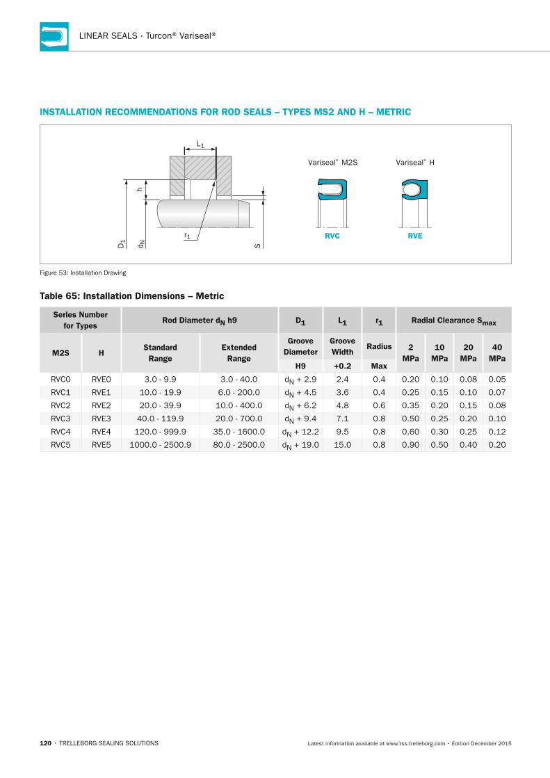
LINEAR SEALS · Turcon® Variseal®
120 • TRELLEBORG SEALING SOLUTIONS Latest information available at www.tss.trelleborg.com • Edition December 2015
InSTALLATIOn RECOMMEnDATIOnS FOR ROD SEALS – TyPES MS2 AnD H – METRIC
RVC RVE
Variseal® M2S Variseal® H
r1
L1h
Sd ND1
Figure 53: Installation Drawing
Table 65: Installation Dimensions – Metric
Series number for Types
Rod Diameter dn h9 D1 L1 r1 Radial Clearance Smax
M2S HStandard Range
Extended Range
Groove Diameter
Groove Width
Radius 2 MPa
10 MPa
20 MPa
40 MPa
H9 +0.2 Max
RVC0 RVE0 3.0 - 9.9 3.0 - 40.0 dN + 2.9 2.4 0.4 0.20 0.10 0.08 0.05
RVC1 RVE1 10.0 - 19.9 6.0 - 200.0 dN + 4.5 3.6 0.4 0.25 0.15 0.10 0.07
RVC2 RVE2 20.0 - 39.9 10.0 - 400.0 dN + 6.2 4.8 0.6 0.35 0.20 0.15 0.08
RVC3 RVE3 40.0 - 119.9 20.0 - 700.0 dN + 9.4 7.1 0.8 0.50 0.25 0.20 0.10
RVC4 RVE4 120.0 - 999.9 35.0 - 1600.0 dN + 12.2 9.5 0.8 0.60 0.30 0.25 0.12
RVC5 RVE5 1000.0 - 2500.9 80.0 - 2500.0 dN + 19.0 15.0 0.8 0.90 0.50 0.40 0.20
FBP_neues_Layout_2015.indb 120 17.10.2016 13:36:18
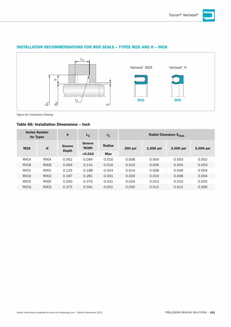
Turcon® Variseal®
TRELLEBORG SEALING SOLUTIONS • 121Latest information available at www.tss.trelleborg.com • Edition December 2015
InSTALLATIOn RECOMMEnDATIOnS FOR ROD SEALS – TyPES M2S AnD H – InCH
RVC RVE
Variseal® M2S Variseal® H
r1
L1
hd ND
1
S
Figure 54: Installation Drawing
Table 66: Installation Dimensions – Inch
Series number for Types
h L1 r1 Radial Clearance Smax
M2S HGroove Depth
Groove Width
Radius300 psi 1,500 psi 3,000 psi 5,000 psi
+0.010 Max
RVCA RVEA 0.062 0.094 0.016 0.008 0.004 0.003 0.002
RVCB RVEB 0.093 0.141 0.016 0.010 0.006 0.004 0.003
RVCC RVEC 0.125 0.188 0.024 0.014 0.008 0.006 0.003
RVCD RVED 0.187 0.281 0.031 0.020 0.010 0.008 0.004
RVCE RVEE 0.250 0.375 0.031 0.024 0.012 0.010 0.005
RVCG RVEG 0.375 0.591 0.031 0.030 0.015 0.012 0.006
FBP_neues_Layout_2015.indb 121 17.10.2016 13:36:18
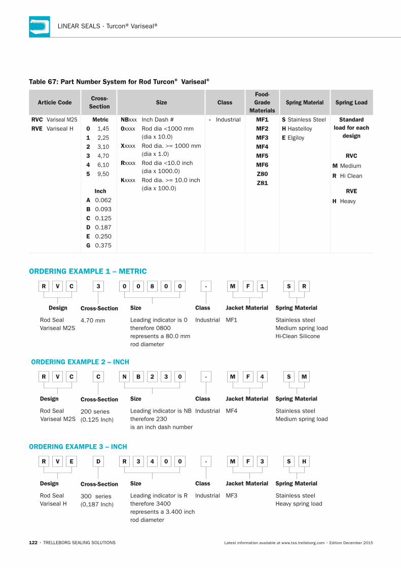
LINEAR SEALS · Turcon® Variseal®
122 • TRELLEBORG SEALING SOLUTIONS Latest information available at www.tss.trelleborg.com • Edition December 2015
Table 67: Part number System for Rod Turcon® Variseal®
Article CodeCross-
SectionSize Class
Food-Grade
MaterialsSpring Material Spring Load
RVC Variseal M2S
RVE Variseal H
Metric
0 1,45
1 2,25
2 3,10
3 4,70
4 6,10
5 9,50
Inch
A 0.062
B 0.093
C 0.125
D 0.187
E 0.250
G 0.375
nBxxx Inch Dash #
0xxxx Rod dia <1000 mm (dia x 10.0)
xxxxx Rod dia. >= 1000 mm (dia x 1.0)
Rxxxx Rod dia <10.0 inch (dia x 1000.0)
Kxxxx Rod dia. >= 10.0 inch (dia x 100.0)
- Industrial MF1
MF2
MF3
MF4
MF5
MF6
Z80
Z81
S Stainless Steel
H Hastelloy
E Elgiloy
Standard load for each
design
RVC
M Medium
R Hi Clean
RVE
H Heavy
ORDERInG ExAMPLE 1 – METRIC
R V C 3 0 0 8 0 0 - M F 1
Cross-Section 4.70 mm
Size Leading indicator is 0 therefore 0800 represents a 80.0 mm rod diameter
Class Industrial
Jacket Material MF1
S R
Spring Material Stainless steelMedium spring loadHi-Clean Silicone
Design Rod SealVariseal M2S
ORDERInG ExAMPLE 2 – InCH
R V C C n B 2 3 0 - M F 4
Cross-Section 200 series (0.125 Inch)
Size Leading indicator is NB therefore 230 is an inch dash number
Class Industrial
Jacket Material MF4
S M
Spring Material Stainless steelMedium spring load
Design Rod SealVariseal M2S
ORDERInG ExAMPLE 3 – InCH
R V E D R 3 4 0 0 - M F 3
Cross-Section 300 series (0,187 Inch)
Size Leading indicator is R therefore 3400 represents a 3.400 inch rod diameter
Class Industrial
Jacket Material MF3
S H
Spring Material Stainless steelHeavy spring load
Design Rod SealVariseal H
FBP_neues_Layout_2015.indb 122 17.10.2016 13:36:19

Turcon® Variseal®
TRELLEBORG SEALING SOLUTIONS • 123Latest information available at www.tss.trelleborg.com • Edition December 2015
FBP_neues_Layout_2015.indb 123 17.10.2016 13:36:19
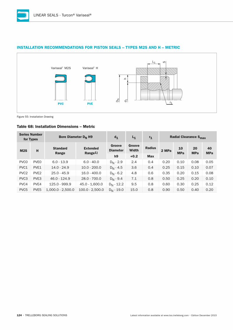
LINEAR SEALS · Turcon® Variseal®
124 • TRELLEBORG SEALING SOLUTIONS Latest information available at www.tss.trelleborg.com • Edition December 2015
InSTALLATIOn RECOMMEnDATIOnS FOR PISTOn SEALS – TyPES M2S AnD H – METRIC
PVC PVE
Variseal® M2S Variseal® H
hd 1D
N
S
r1
L1
Figure 55: Installation Drawing
Table 68: Installation Dimensions – Metric
Series number for Types
Bore Diameter Dn H9 d1 L1 r1 Radial Clearance Smax
M2S HStandard Range
Extended Range1)
Groove Diameter
Groove Width
Radius2 MPa
10 MPa
20 MPa
40 MPa
h9 +0.2 Max
PVC0 PVE0 6.0 - 13.9 6.0 - 40.0 DN - 2.9 2.4 0.4 0.20 0.10 0.08 0.05
PVC1 PVE1 14.0 - 24.9 10.0 - 200.0 DN - 4.5 3.6 0.4 0.25 0.15 0.10 0.07
PVC2 PVE2 25.0 - 45.9 16.0 - 400.0 DN - 6.2 4.8 0.6 0.35 0.20 0.15 0.08
PVC3 PVE3 46.0 - 124.9 28.0 - 700.0 DN - 9.4 7.1 0.8 0.50 0.25 0.20 0.10
PVC4 PVE4 125.0 - 999.9 45.0 - 1,600.0 DN - 12.2 9.5 0.8 0.60 0.30 0.25 0.12
PVC5 PVE5 1,000.0 - 2,500.0 100.0 - 2,500.0 DN - 19.0 15.0 0.8 0.90 0.50 0.40 0.20
FBP_neues_Layout_2015.indb 124 17.10.2016 13:36:20
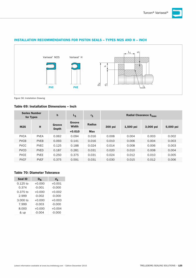
Turcon® Variseal®
TRELLEBORG SEALING SOLUTIONS • 125Latest information available at www.tss.trelleborg.com • Edition December 2015
InSTALLATIOn RECOMMEnDATIOnS FOR PISTOn SEALS – TyPES M2S AnD H – InCH
PVC PVE
Variseal® M2S Variseal® H
hd 1D
N
S
r1
L1
Figure 56: Installation Drawing
Table 69: Installation Dimensions – Inch
Series number for Types
h L1 r1 Radial Clearance Smax
M2S HGroove Depth
Groove Width
Radius300 psi 1,500 psi 3,000 psi 5,000 psi
+0.010 Max
PVCA PVEA 0.062 0.094 0.016 0.008 0.004 0.003 0.002
PVCB PVEB 0.093 0.141 0.016 0.010 0.006 0.004 0.003
PVCC PVEC 0.125 0.188 0.024 0.014 0.008 0.006 0.003
PVCD PVED 0.187 0.281 0.031 0.020 0.010 0.008 0.004
PVCE PVEE 0.250 0.375 0.031 0.024 0.012 0.010 0.005
PVCF PVEF 0.375 0.591 0.031 0.030 0.015 0.012 0.006
Table 70: Diameter Tolerance
Seal ID Dn d10.125 to 0.374
+0.000 -0.001
+0.001 -0.000
0.375 to 2.999
+0.000 -0.002
+0.002 -0.000
3.000 to 7.999
+0.000 -0.003
+0.003 -0.000
8.000 & up
+0.000 -0.004
+0.004 -0.000
FBP_neues_Layout_2015.indb 125 17.10.2016 13:36:20
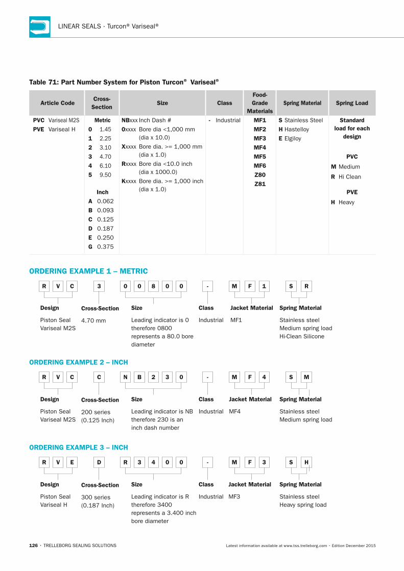
LINEAR SEALS · Turcon® Variseal®
126 • TRELLEBORG SEALING SOLUTIONS Latest information available at www.tss.trelleborg.com • Edition December 2015
Table 71: Part number System for Piston Turcon® Variseal®
Article CodeCross-
SectionSize Class
Food-Grade
MaterialsSpring Material Spring Load
PVC Variseal M2S
PVE Variseal H
Metric
0 1.45
1 2.25
2 3.10
3 4.70
4 6.10
5 9.50
Inch
A 0.062
B 0.093
C 0.125
D 0.187
E 0.250
G 0.375
nBxxx Inch Dash #
0xxxx Bore dia <1,000 mm (dia x 10.0)
xxxxx Bore dia. >= 1,000 mm (dia x 1.0)
Rxxxx Bore dia <10.0 inch (dia x 1000.0)
Kxxxx Bore dia. >= 1,000 inch (dia x 1.0)
- Industrial MF1
MF2
MF3
MF4
MF5
MF6
Z80
Z81
S Stainless Steel
H Hastelloy
E Elgiloy
Standard load for each
design
PVC
M Medium
R Hi Clean
PVE
H Heavy
ORDERInG ExAMPLE 1 – METRIC
R V C 3 0 0 8 0 0 - M F 1
Cross-Section 4.70 mm
Size Leading indicator is 0 therefore 0800 represents a 80.0 bore diameter
Class Industrial
Jacket Material MF1
S R
Spring Material Stainless steelMedium spring loadHi-Clean Silicone
Design Piston SealVariseal M2S
ORDERInG ExAMPLE 2 – InCH
R V C C n B 2 3 0 - M F 4
Cross-Section 200 series (0.125 Inch)
Size Leading indicator is NB therefore 230 is an inch dash number
Class Industrial
Jacket Material MF4
S M
Spring Material Stainless steelMedium spring load
Design Piston SealVariseal M2S
ORDERInG ExAMPLE 3 – InCH
R V E D R 3 4 0 0 - M F 3
Cross-Section 300 series (0.187 Inch)
Size Leading indicator is R therefore 3400 represents a 3.400 inch bore diameter
Class Industrial
Jacket Material MF3
S H
Spring Material Stainless steelHeavy spring load
Design Piston SealVariseal H
FBP_neues_Layout_2015.indb 126 17.10.2016 13:36:21

Turcon® Variseal®
TRELLEBORG SEALING SOLUTIONS • 127Latest information available at www.tss.trelleborg.com • Edition December 2015
Rod/Face Seal
Sealing Piston
Double Decker
Conical Seal
Seal to overcome largeeccentricity.
Double acting sealing pistonfor a.o. filling machines.
Can be adapted to anygroove dimension.With encapsulated spring.
This isolates the springfrom the media.
Turcon® Roto Variseal®
CryogenicDesign optimised for lowtemperature use. Minimizes effect of contraction forces.
Turcon® Roto® Variseal®
Helical Sanitary
Turcon® Roto Variseal®
Sanitary
With encapsulated spring.This isolates the springfrom the media.For static applications.
High Pressure SystemSealing system for extremepressures or big extrusion gaps.
Variseal® Mini-pistonDesign for small applications,such as pipettes.
Captive Variseal® HProtects against pressure surges.
Sealing PistonCompact sealing piston.
Figure 57: Special Variseals
FBP_neues_Layout_2015.indb 127 17.10.2016 13:36:21
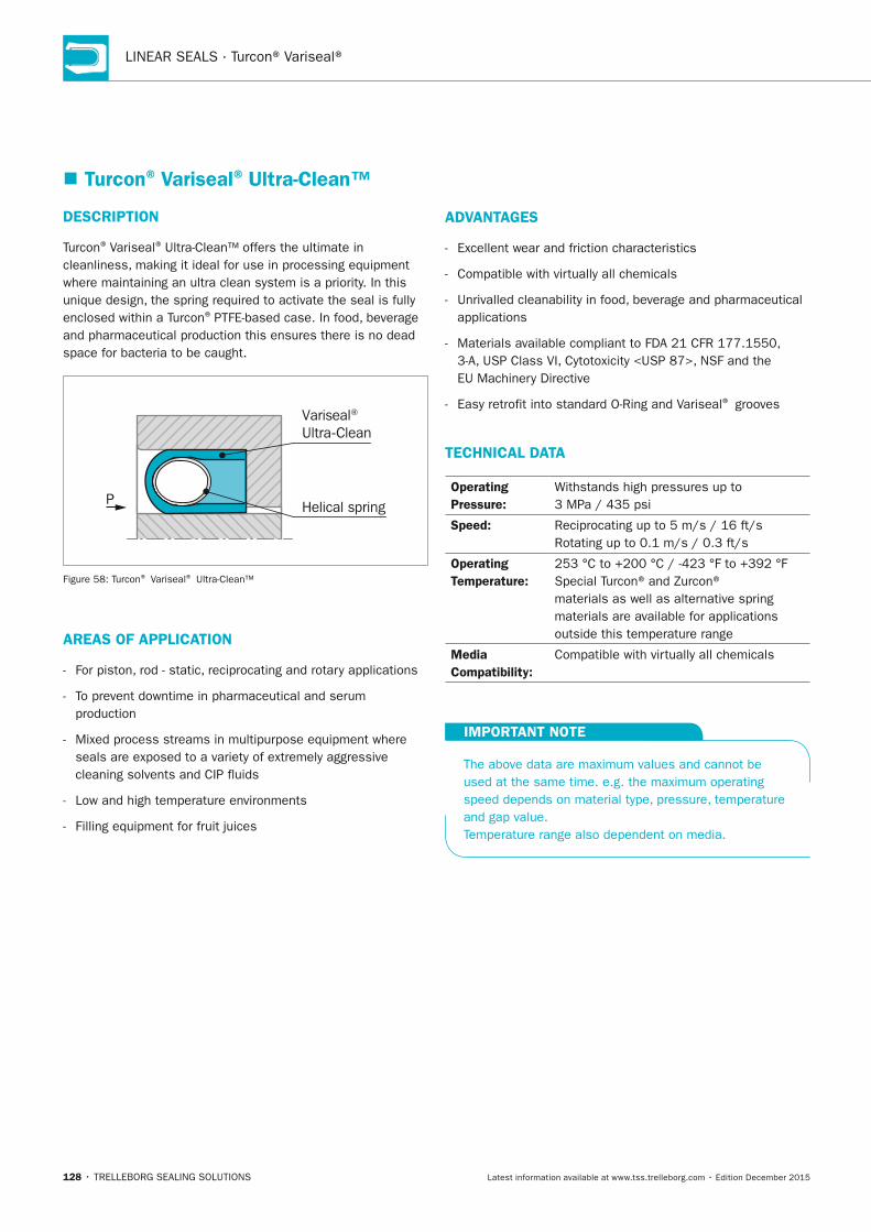
LINEAR SEALS · Turcon® Variseal®
128 • TRELLEBORG SEALING SOLUTIONS Latest information available at www.tss.trelleborg.com • Edition December 2015
� Turcon® Variseal® Ultra-Clean™
DESCRIPTIOn
Turcon® Variseal® Ultra-Clean™ offers the ultimate in cleanliness, making it ideal for use in processing equipment where maintaining an ultra clean system is a priority. In this unique design, the spring required to activate the seal is fully enclosed within a Turcon® PTFE-based case. In food, beverage and pharmaceutical production this ensures there is no dead space for bacteria to be caught.
Variseal® Ultra-Clean
Helical springP
Figure 58: Turcon® Variseal® Ultra-Clean™
AREAS OF APPLICATIOn
- For piston, rod - static, reciprocating and rotary applications
- To prevent downtime in pharmaceutical and serum production
- Mixed process streams in multipurpose equipment where seals are exposed to a variety of extremely aggressive cleaning solvents and CIP fluids
- Low and high temperature environments
- Filling equipment for fruit juices
ADVAnTAGES
- Excellent wear and friction characteristics
- Compatible with virtually all chemicals
- Unrivalled cleanability in food, beverage and pharmaceutical applications
- Materials available compliant to FDA 21 CFR 177.1550, 3-A, USP Class VI, Cytotoxicity <USP 87>, NSF and the EU Machinery Directive
- Easy retrofit into standard O-Ring and Variseal® grooves
TECHnICAL DATA
Operating Pressure:
Withstands high pressures up to 3 MPa / 435 psi
Speed: Reciprocating up to 5 m/s / 16 ft/s Rotating up to 0.1 m/s / 0.3 ft/s
Operating Temperature:
253 °C to +200 °C / -423 °F to +392 °F Special Turcon® and Zurcon® materials as well as alternative spring materials are available for applications outside this temperature range
Media Compatibility:
Compatible with virtually all chemicals
IMPORTAnT nOTE
The above data are maximum values and cannot be used at the same time. e.g. the maximum operating speed depends on material type, pressure, temperature and gap value. Temperature range also dependent on media.
FBP_neues_Layout_2015.indb 128 17.10.2016 13:36:22
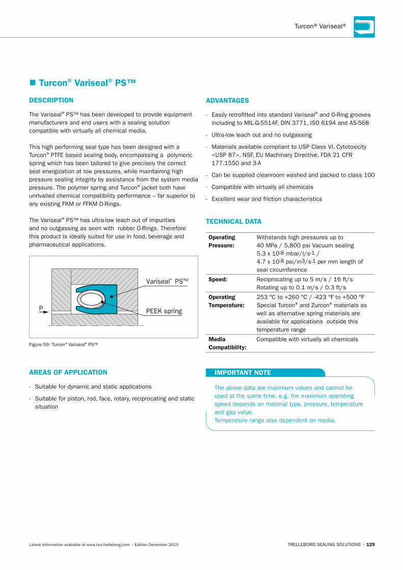
Turcon® Variseal®
TRELLEBORG SEALING SOLUTIONS • 129Latest information available at www.tss.trelleborg.com • Edition December 2015
� Turcon® Variseal® PS™
DESCRIPTIOn
The Variseal® PS™ has been developed to provide equipment manufacturers and end users with a sealing solution compatible with virtually all chemical media.
This high performing seal type has been designed with a Turcon® PTFE based sealing body, encompassing a polymeric spring which has been tailored to give precisely the correct seal energization at low pressures, while maintaining high pressure sealing integrity by assistance from the system media pressure. The polymer spring and Turcon® jacket both have unrivalled chemical compatibility performance – far superior to any existing FKM or FFKM O-Rings.
The Variseal® PS™ has ultra-low leach out of impurities and no outgassing as seen with rubber O-Rings. Therefore this product is ideally suited for use in food, beverage and pharmaceutical applications.
Variseal® PSTM
PEEK springP
Figure 59: Turcon® Variseal® PS™
AREAS OF APPLICATIOn
- Suitable for dynamic and static applications
- Suitable for piston, rod, face, rotary, reciprocating and static situation
ADVAnTAGES
- Easily retrofitted into standard Variseal® and O-Ring grooves including to MIL-G-5514F, DIN 3771, ISO 6194 and AS-568
- Ultra-low leach out and no outgassing
- Materials available compliant to USP Class VI, Cytotoxicity <USP 87>, NSF, EU Machinary Directive, FDA 21 CFR 177.1550 and 3-A
- Can be supplied cleanroom washed and packed to class 100
- Compatible with virtually all chemicals
- Excellent wear and friction characteristics
TECHnICAL DATA
Operating Pressure:
Withstands high pressures up to 40 MPa / 5,800 psi Vacuum sealing 5.3 x 10⁻⁸ mbar/l/s-1 / 4.7 x 10⁻⁸ psi/in3/s-1 per mm length of seal circumference
Speed: Reciprocating up to 5 m/s / 16 ft/s Rotating up to 0.1 m/s / 0.3 ft/s
Operating Temperature:
253 °C to +260 °C / -423 °F to +500 °F Special Turcon® and Zurcon® materials as well as alternative spring materials are available for applications outside this temperature range
Media Compatibility:
Compatible with virtually all chemicals
IMPORTAnT nOTE
The above data are maximum values and cannot be used at the same time. e.g. the maximum operating speed depends on material type, pressure, temperature and gap value. Temperature range also dependent on media.
FBP_neues_Layout_2015.indb 129 17.10.2016 13:36:23

LINEAR SEALS · Turcon® Variseal®
130 • TRELLEBORG SEALING SOLUTIONS Latest information available at www.tss.trelleborg.com • Edition December 2015
FBP_neues_Layout_2015.indb 130 17.10.2016 13:36:23
LINEAR SEALS
TRELLEBORG SEALING SOLUTIONS • 131Latest information available at www.tss.trelleborg.com • Edition December 2015
Turcon®Turcon®TurconGlyd RingTurconGlyd RingTurcon ®High operational reliability
Robust seal design
Double-acting
Very low friction
Very low wear, long service life
Stick-slip-free operation
High static / dynamic tightness
Simple housing design - one piece piston / gland possible
Easy installation
FBP_neues_Layout_2015.indb 131 17.10.2016 13:36:26

LINEAR SEALS · Turcon® Glyd Ring®
132 • TRELLEBORG SEALING SOLUTIONS Latest information available at www.tss.trelleborg.com • Edition December 2015
FBP_neues_Layout_2015.indb 132 17.10.2016 13:36:26
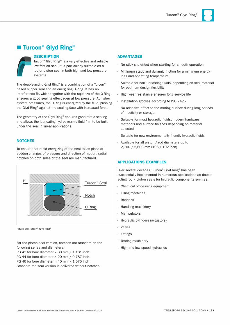
Turcon® Glyd Ring®
TRELLEBORG SEALING SOLUTIONS • 133Latest information available at www.tss.trelleborg.com • Edition December 2015
DESCRIPTIOnTurcon® Glyd Ring® is a very effective and reliable low friction seal. It is particularly suitable as a rod or piston seal in both high and low pressure systems.
The double-acting Glyd Ring® is a combination of a Turcon®
based slipper seal and an energizing O-Ring. It has an interference fit, which together with the squeeze of the O-Ring, ensures a good sealing effect even at low pressure. At higher system pressures, the O-Ring is energized by the fluid, pushing the Glyd Ring® against the sealing face with increased force.
The geometry of the Glyd Ring® ensures good static sealing and allows the lubricating hydrodynamic fluid film to be built under the seal in linear applications.
nOTCHES
To ensure that rapid energizing of the seal takes place at sudden changes of pressure and direction of motion, radial notches on both sides of the seal are manufactured.
P Turcon® Seal
O-Ring
Notch
Figure 60: Turcon® Glyd Ring®
For the piston seal version, notches are standard on the following series and diameters:PG 42 for bore diameter > 30 mm / 1.181 inchPG 44 for bore diameter > 20 mm / 0.787 inchPG 46 for bore diameter > 40 mm / 1.575 inchStandard rod seal version is delivered without notches.
ADVAnTAGES
- No stick-slip effect when starting for smooth operation
- Minimum static and dynamic friction for a minimum energy loss and operating temperature
- Suitable for non-lubricating fluids, depending on seal material for optimum design flexibility
- High wear resistance ensures long service life
- Installation grooves according to ISO 7425
- No adhesive effect to the mating surface during long periods of inactivity or storage
- Suitable for most hydraulic fluids, modern hardware materials and surface finishes depending on material selected
- Suitable for new environmentally friendly hydraulic fluids
- Available for all piston / rod diameters up to 2,700 / 2,600 mm (106 / 102 inch)
APPLICATIOnS ExAMPLES
Over several decades, Turcon® Glyd Ring® has been successfully implemented in numerous applications as double acting rod / piston seals for hydraulic components such as:
- Chemical processing equipment
- Filling machines
- Robotics
- Handling machinery
- Manipulators
- Hydraulic cylinders (actuators)
- Valves
- Fittings
- Testing machinery
- High and low speed hydraulics
� Turcon® Glyd Ring®
FBP_neues_Layout_2015.indb 133 17.10.2016 13:36:28
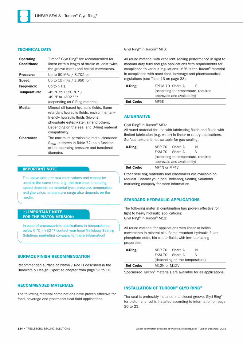
LINEAR SEALS · Turcon® Glyd Ring®
134 • TRELLEBORG SEALING SOLUTIONS Latest information available at www.tss.trelleborg.com • Edition December 2015
TECHnICAL DATA
Operating Conditions:
Turcon® Glyd Ring® are recommended for linear (with a length of stroke at least twice the groove width) and helical movements.
Pressure: Up to 60 MPa / 8,702 psi
Speed: Up to 15 m/s / 2,950 fpm
Frequency: Up to 5 Hz.
Temperature: -45 °C to +150 °C* / -49 °F to +302 °F* (depending on O-Ring material)
Media: Mineral oil based hydraulic fluids, flame retardant hydraulic fluids, environmentally-friendly hydraulic fluids (bio-oils), phosphate ester, water, air and others. Depending on the seal and O-Ring material compatibility.
Clearance: The maximum permissible radial clearance Smax is shown in Table 72, as a function of the operating pressure and functional diameter.
IMPORTAnT nOTE
The above data are maximum values and cannot be used at the same time, e.g. the maximum operating speed depends on material type, pressure, temperature and gap value. emperature range also depends on the media.
*) IMPORTAnT nOTE FOR THE PISTOn VERSIOn:
In case of unpressurized applications in temperatures below 0 °C / +32 °F contact your local Trelleborg Sealing Solutions marketing company for more information!
SURFACE FInISH RECOMMEnDATIOn
Recommended surface of Piston / Rod is described in the Hardware & Design Expertise chapter from page 13 to 16.
RECOMMEnDED MATERIALS
The following material combinations have proven effective for food, beverage and pharmaceutical fluid applications:
Glyd Ring® in Turcon® MF6:
All round material with excellent sealing performance in light to medium duty fluid and gas applications with requirements for compliance to various regulations. MF6 is the Turcon® material in compliance with most food, beverage and pharmaceutical regulations (see Table 13 on page 33).
O-Ring: EPDM 70 Shore A E (according to temperature, required approvals and availability)
Set Code: MF6E
ALTERnATIVE
Glyd Ring® in Turcon® MF4:All-round material for use with lubricating fluids and fluids with limited lubrication (e.g. water) in linear or rotary applications. Surface texture is not suitable for gas sealing.
O-Ring: NBR 70 Shore A N FKM 70 Shore A V (according to temperature, required approvals and availability)
Set Code: MF4N or MF4V
Other seal ring materials and elastomers are available on request. Contact your local Trelleborg Sealing Solutions marketing company for more information.
STAnDARD HyDRAULIC APPLICATIOnS
The following material combination has proven effective for light to heavy hydraulic applications:Glyd Ring® in Turcon® M12:
All round material for applications with linear or helical movements in mineral oils, flame retardant hydraulic fluids, phosphate ester, bio-oils or fluids with low lubricating properties.
O-Ring: NBR 70 Shore A N FKM 70 Shore A V (depending on the temperature)
Set Code: M12N or M12V
Specialized Turcon® materials are available for all applications.
InSTALLATIOn OF TURCOn® GLyD RInG®
The seal is preferably installed in a closed groove. Glyd Ring®
for piston and rod is installed according to information on page 20 to 23.
FBP_neues_Layout_2015.indb 134 17.10.2016 13:36:28

Turcon® Glyd Ring®
TRELLEBORG SEALING SOLUTIONS • 135Latest information available at www.tss.trelleborg.com • Edition December 2015
FBP_neues_Layout_2015.indb 135 17.10.2016 13:36:28
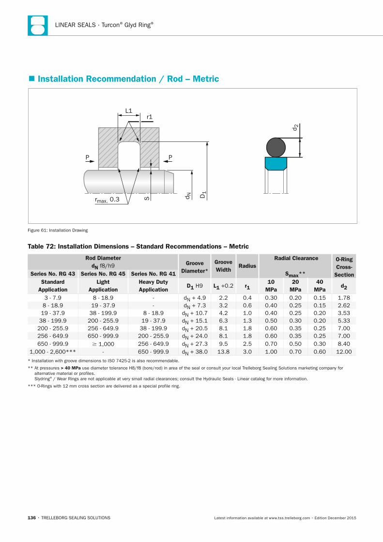
LINEAR SEALS · Turcon® Glyd Ring®
136 • TRELLEBORG SEALING SOLUTIONS Latest information available at www.tss.trelleborg.com • Edition December 2015
� Installation Recommendation / Rod – Metric
rmax. 0.3 d N D1
L1r1
P P
d 2
S
Figure 61: Installation Drawing
Table 72: Installation Dimensions – Standard Recommendations – Metric
Rod Diameter dn f8/h9 Groove
Diameter*
Groove Width
Radius Radial Clearance
Smax**
O-Ring Cross-
SectionSeries no. RG 43 Series no. RG 45 Series no. RG 41 Standard
Application Light
Application Heavy Duty Application
D1 H9 L1 +0.2 r1 10
MPa 20
MPa 40
MPa d2
3 - 7.9 8 - 18.9 - dN + 4.9 2.2 0.4 0.30 0.20 0.15 1.78 8 - 18.9 19 - 37.9 - dN + 7.3 3.2 0.6 0.40 0.25 0.15 2.62 19 - 37.9 38 - 199.9 8 - 18.9 dN + 10.7 4.2 1.0 0.40 0.25 0.20 3.53 38 - 199.9 200 - 255.9 19 - 37.9 dN + 15.1 6.3 1.3 0.50 0.30 0.20 5.33
200 - 255.9 256 - 649.9 38 - 199.9 dN + 20.5 8.1 1.8 0.60 0.35 0.25 7.00 256 - 649.9 650 - 999.9 200 - 255.9 dN + 24.0 8.1 1.8 0.60 0.35 0.25 7.00 650 - 999.9 1,000 256 - 649.9 dN + 27.3 9.5 2.5 0.70 0.50 0.30 8.40
1,000 - 2,600*** - 650 - 999.9 dN + 38.0 13.8 3.0 1.00 0.70 0.60 12.00
* Installation with groove dimensions to ISO 7425-2 is also recommendable.
** At pressures > 40 MPa use diameter tolerance H8/f8 (bore/rod) in area of the seal or consult your local Trelleborg Sealing Solutions marketing company for alternative material or profiles. Slydring® / Wear Rings are not applicable at very small radial clearances; consult the Hydraulic Seals - Linear catalog for more information.
*** O-Rings with 12 mm cross section are delivered as a special profile ring.
FBP_neues_Layout_2015.indb 136 17.10.2016 13:36:28
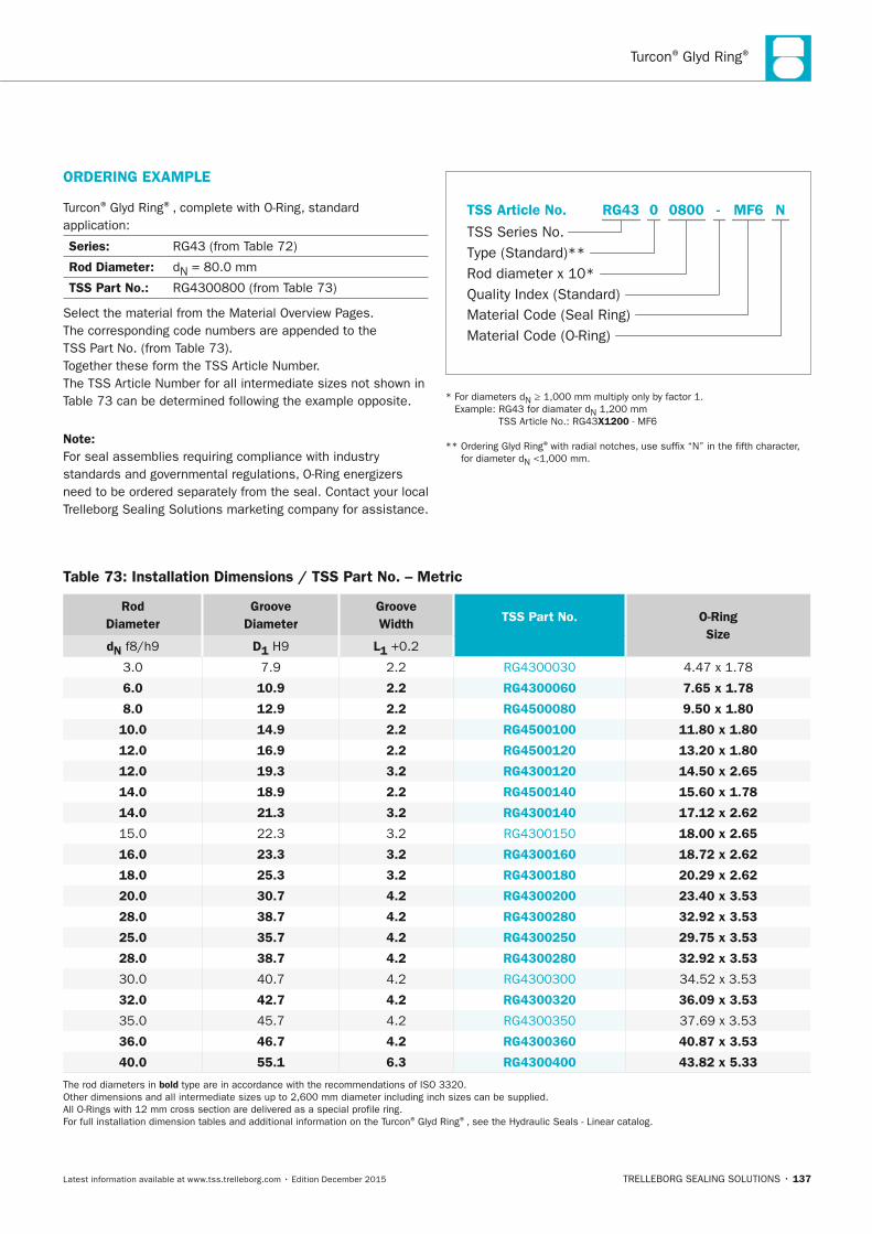
Turcon® Glyd Ring®
TRELLEBORG SEALING SOLUTIONS • 137Latest information available at www.tss.trelleborg.com • Edition December 2015
Table 73: Installation Dimensions / TSS Part no. – Metric
Rod Diameter
Groove Diameter
Groove Width TSS Part no.
O-Ring Size
dn f8/h9 D1 H9 L1 +0.2
3.0 7.9 2.2 RG4300030 4.47 x 1.78
6.0 10.9 2.2 RG4300060 7.65 x 1.78
8.0 12.9 2.2 RG4500080 9.50 x 1.80
10.0 14.9 2.2 RG4500100 11.80 x 1.80
12.0 16.9 2.2 RG4500120 13.20 x 1.80
12.0 19.3 3.2 RG4300120 14.50 x 2.65
14.0 18.9 2.2 RG4500140 15.60 x 1.78
14.0 21.3 3.2 RG4300140 17.12 x 2.62
15.0 22.3 3.2 RG4300150 18.00 x 2.65
16.0 23.3 3.2 RG4300160 18.72 x 2.62
18.0 25.3 3.2 RG4300180 20.29 x 2.62
20.0 30.7 4.2 RG4300200 23.40 x 3.53
28.0 38.7 4.2 RG4300280 32.92 x 3.53
25.0 35.7 4.2 RG4300250 29.75 x 3.53
28.0 38.7 4.2 RG4300280 32.92 x 3.53
30.0 40.7 4.2 RG4300300 34.52 x 3.53
32.0 42.7 4.2 RG4300320 36.09 x 3.53
35.0 45.7 4.2 RG4300350 37.69 x 3.53
36.0 46.7 4.2 RG4300360 40.87 x 3.53
40.0 55.1 6.3 RG4300400 43.82 x 5.33
The rod diameters in bold type are in accordance with the recommendations of ISO 3320. Other dimensions and all intermediate sizes up to 2,600 mm diameter including inch sizes can be supplied. All O-Rings with 12 mm cross section are delivered as a special profile ring. For full installation dimension tables and additional information on the Turcon® Glyd Ring®, see the Hydraulic Seals - Linear catalog.
note:For seal assemblies requiring compliance with industry standards and governmental regulations, O-Ring energizers need to be ordered separately from the seal. Contact your local Trelleborg Sealing Solutions marketing company for assistance.
Material Code (Seal Ring)
TSS Series No.
TSS Article No.
Material Code (O-Ring)
Rod diameter x 10*Quality Index (Standard)
Type (Standard)**
MF6 NRG43 -0 0800
* For diameters dN ≥ 1,000 mm multiply only by factor 1. Example: RG43 for diamater dN 1,200 mm
TSS Article No.: RG43x1200 - MF6
** Ordering Glyd Ring® with radial notches, use suffix “N” in the fifth character, for diameter dN <1,000 mm.
ORDERInG ExAMPLE
Turcon® Glyd Ring®, complete with O-Ring, standard application:
Series: RG43 (from Table 72)
Rod Diameter: dN = 80.0 mm
TSS Part no.: RG4300800 (from Table 73)
Select the material from the Material Overview Pages. The corresponding code numbers are appended to the TSS Part No. (from Table 73).Together these form the TSS Article Number. The TSS Article Number for all intermediate sizes not shown in Table 73 can be determined following the example opposite.
FBP_neues_Layout_2015.indb 137 17.10.2016 13:36:29
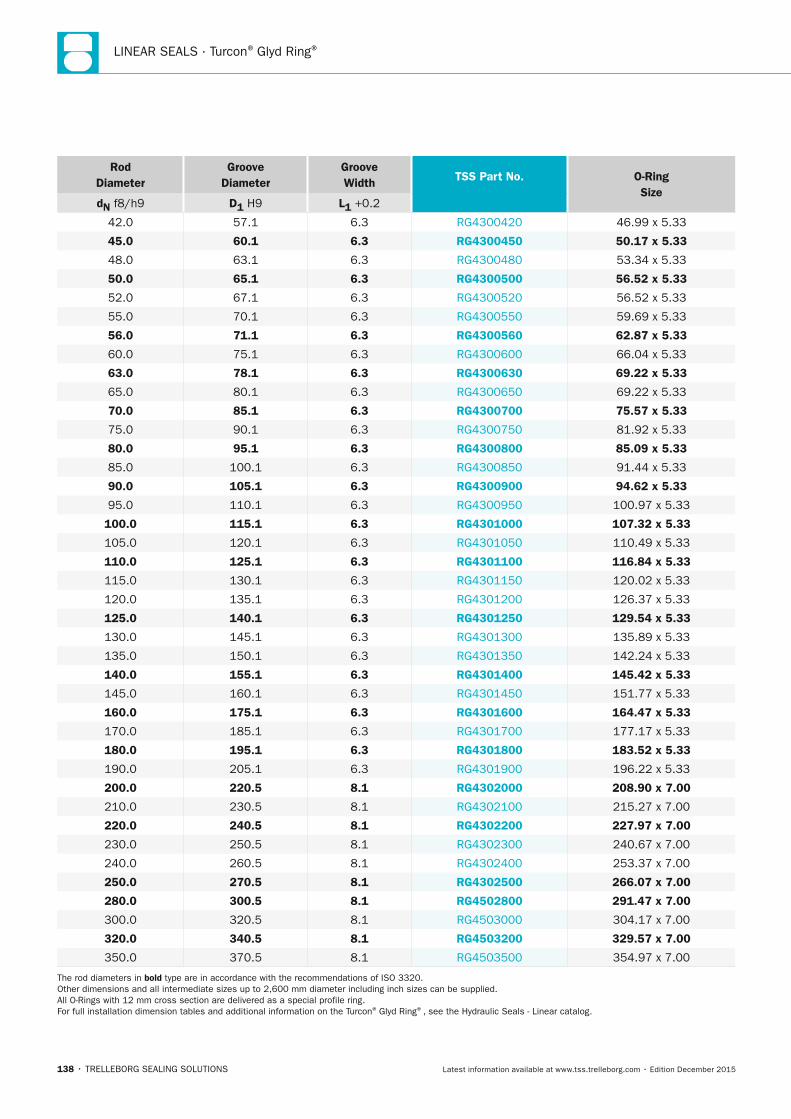
LINEAR SEALS · Turcon® Glyd Ring®
138 • TRELLEBORG SEALING SOLUTIONS Latest information available at www.tss.trelleborg.com • Edition December 2015
Rod Diameter
Groove Diameter
Groove Width TSS Part no.
O-Ring Size
dn f8/h9 D1 H9 L1 +0.2
42.0 57.1 6.3 RG4300420 46.99 x 5.33
45.0 60.1 6.3 RG4300450 50.17 x 5.33
48.0 63.1 6.3 RG4300480 53.34 x 5.33
50.0 65.1 6.3 RG4300500 56.52 x 5.33
52.0 67.1 6.3 RG4300520 56.52 x 5.33
55.0 70.1 6.3 RG4300550 59.69 x 5.33
56.0 71.1 6.3 RG4300560 62.87 x 5.33
60.0 75.1 6.3 RG4300600 66.04 x 5.33
63.0 78.1 6.3 RG4300630 69.22 x 5.33
65.0 80.1 6.3 RG4300650 69.22 x 5.33
70.0 85.1 6.3 RG4300700 75.57 x 5.33
75.0 90.1 6.3 RG4300750 81.92 x 5.33
80.0 95.1 6.3 RG4300800 85.09 x 5.33
85.0 100.1 6.3 RG4300850 91.44 x 5.33
90.0 105.1 6.3 RG4300900 94.62 x 5.33
95.0 110.1 6.3 RG4300950 100.97 x 5.33
100.0 115.1 6.3 RG4301000 107.32 x 5.33
105.0 120.1 6.3 RG4301050 110.49 x 5.33
110.0 125.1 6.3 RG4301100 116.84 x 5.33
115.0 130.1 6.3 RG4301150 120.02 x 5.33
120.0 135.1 6.3 RG4301200 126.37 x 5.33
125.0 140.1 6.3 RG4301250 129.54 x 5.33
130.0 145.1 6.3 RG4301300 135.89 x 5.33
135.0 150.1 6.3 RG4301350 142.24 x 5.33
140.0 155.1 6.3 RG4301400 145.42 x 5.33
145.0 160.1 6.3 RG4301450 151.77 x 5.33
160.0 175.1 6.3 RG4301600 164.47 x 5.33
170.0 185.1 6.3 RG4301700 177.17 x 5.33
180.0 195.1 6.3 RG4301800 183.52 x 5.33
190.0 205.1 6.3 RG4301900 196.22 x 5.33
200.0 220.5 8.1 RG4302000 208.90 x 7.00
210.0 230.5 8.1 RG4302100 215.27 x 7.00
220.0 240.5 8.1 RG4302200 227.97 x 7.00
230.0 250.5 8.1 RG4302300 240.67 x 7.00
240.0 260.5 8.1 RG4302400 253.37 x 7.00
250.0 270.5 8.1 RG4302500 266.07 x 7.00
280.0 300.5 8.1 RG4502800 291.47 x 7.00
300.0 320.5 8.1 RG4503000 304.17 x 7.00
320.0 340.5 8.1 RG4503200 329.57 x 7.00
350.0 370.5 8.1 RG4503500 354.97 x 7.00
The rod diameters in bold type are in accordance with the recommendations of ISO 3320. Other dimensions and all intermediate sizes up to 2,600 mm diameter including inch sizes can be supplied. All O-Rings with 12 mm cross section are delivered as a special profile ring. For full installation dimension tables and additional information on the Turcon® Glyd Ring®, see the Hydraulic Seals - Linear catalog.
FBP_neues_Layout_2015.indb 138 17.10.2016 13:36:29
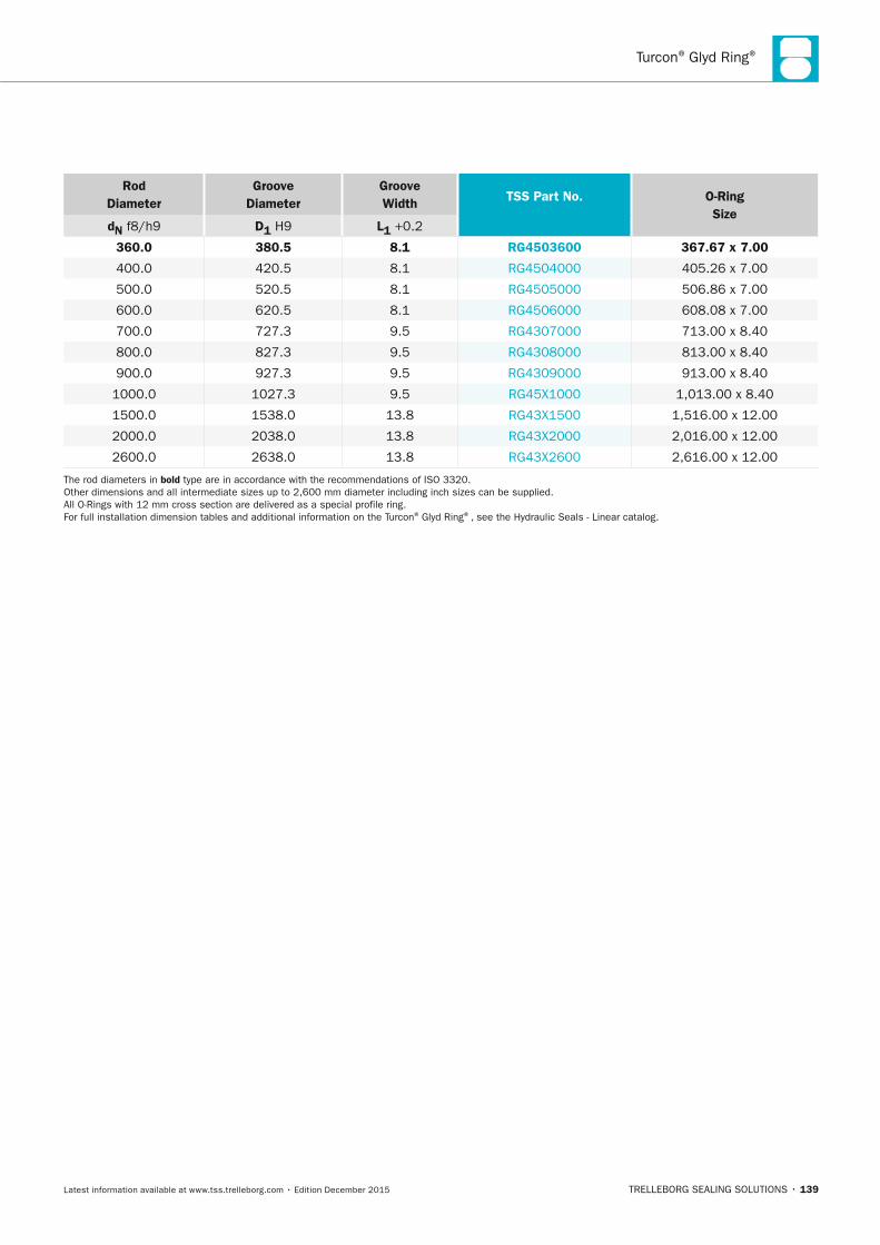
Turcon® Glyd Ring®
TRELLEBORG SEALING SOLUTIONS • 139Latest information available at www.tss.trelleborg.com • Edition December 2015
Rod Diameter
Groove Diameter
Groove Width TSS Part no.
O-Ring Size
dn f8/h9 D1 H9 L1 +0.2
360.0 380.5 8.1 RG4503600 367.67 x 7.00
400.0 420.5 8.1 RG4504000 405.26 x 7.00
500.0 520.5 8.1 RG4505000 506.86 x 7.00
600.0 620.5 8.1 RG4506000 608.08 x 7.00
700.0 727.3 9.5 RG4307000 713.00 x 8.40
800.0 827.3 9.5 RG4308000 813.00 x 8.40
900.0 927.3 9.5 RG4309000 913.00 x 8.40
1000.0 1027.3 9.5 RG45X1000 1,013.00 x 8.40
1500.0 1538.0 13.8 RG43X1500 1,516.00 x 12.00
2000.0 2038.0 13.8 RG43X2000 2,016.00 x 12.00
2600.0 2638.0 13.8 RG43X2600 2,616.00 x 12.00
The rod diameters in bold type are in accordance with the recommendations of ISO 3320. Other dimensions and all intermediate sizes up to 2,600 mm diameter including inch sizes can be supplied. All O-Rings with 12 mm cross section are delivered as a special profile ring. For full installation dimension tables and additional information on the Turcon® Glyd Ring®, see the Hydraulic Seals - Linear catalog.
FBP_neues_Layout_2015.indb 139 17.10.2016 13:36:30
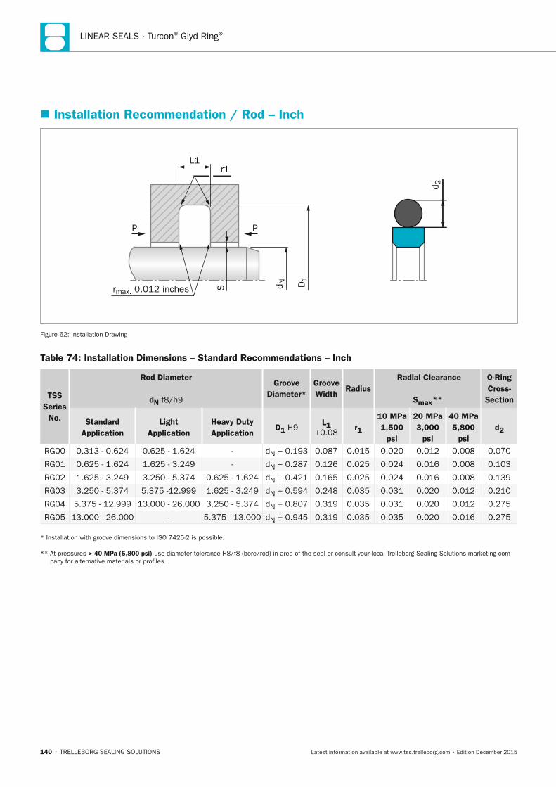
LINEAR SEALS · Turcon® Glyd Ring®
140 • TRELLEBORG SEALING SOLUTIONS Latest information available at www.tss.trelleborg.com • Edition December 2015
� Installation Recommendation / Rod – Inch
rmax. 0.012 inches d N D1
L1r1
SP P
d 2
Figure 62: Installation Drawing
Table 74: Installation Dimensions – Standard Recommendations – Inch
TSS Series
no.
Rod Diameter
dn f8/h9
Groove Diameter*
Groove Width
Radius Radial Clearance
Smax**
O-Ring Cross-
Section
Standard Application
Light Application
Heavy Duty Application
D1 H9 L1
+0.08 r1
10 MPa 1,500
psi
20 MPa 3,000
psi
40 MPa 5,800
psi d2
RG00 0.313 - 0.624 0.625 - 1.624 - dN + 0.193 0.087 0.015 0.020 0.012 0.008 0.070
RG01 0.625 - 1.624 1.625 - 3.249 - dN + 0.287 0.126 0.025 0.024 0.016 0.008 0.103
RG02 1.625 - 3.249 3.250 - 5.374 0.625 - 1.624 dN + 0.421 0.165 0.025 0.024 0.016 0.008 0.139
RG03 3.250 - 5.374 5.375 -12.999 1.625 - 3.249 dN + 0.594 0.248 0.035 0.031 0.020 0.012 0.210
RG04 5.375 - 12.999 13.000 - 26.000 3.250 - 5.374 dN + 0.807 0.319 0.035 0.031 0.020 0.012 0.275
RG05 13.000 - 26.000 - 5.375 - 13.000 dN + 0.945 0.319 0.035 0.035 0.020 0.016 0.275
* Installation with groove dimensions to ISO 7425-2 is possible.
** At pressures > 40 MPa (5,800 psi) use diameter tolerance H8/f8 (bore/rod) in area of the seal or consult your local Trelleborg Sealing Solutions marketing com-pany for alternative materials or profiles.
FBP_neues_Layout_2015.indb 140 17.10.2016 13:36:30
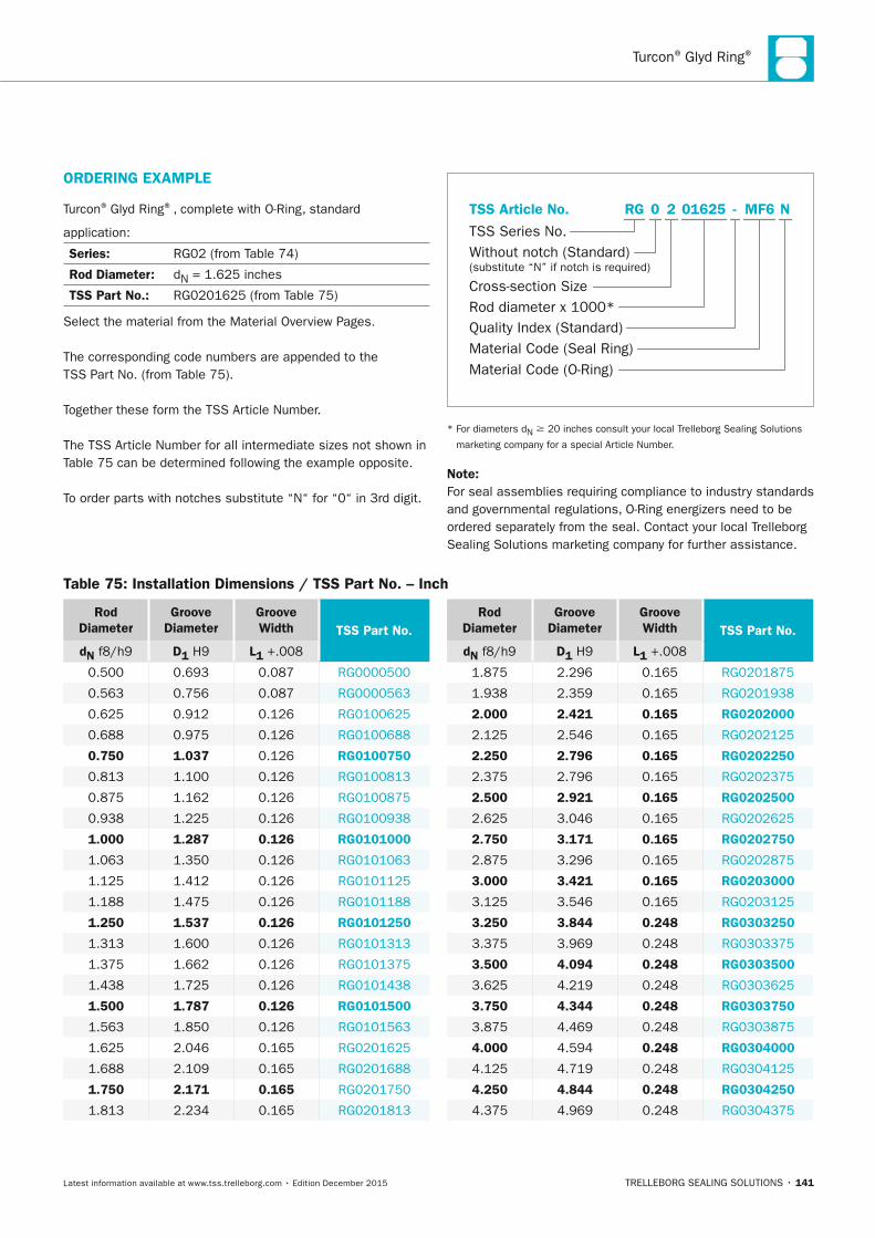
Turcon® Glyd Ring®
TRELLEBORG SEALING SOLUTIONS • 141Latest information available at www.tss.trelleborg.com • Edition December 2015
ORDERInG ExAMPLE
Turcon® Glyd Ring®, complete with O-Ring, standard
application:
Series: RG02 (from Table 74)
Rod Diameter: dN = 1.625 inches
TSS Part no.: RG0201625 (from Table 75)
Select the material from the Material Overview Pages.
The corresponding code numbers are appended to the TSS Part No. (from Table 75).
Together these form the TSS Article Number.
The TSS Article Number for all intermediate sizes not shown in Table 75 can be determined following the example opposite.
To order parts with notches substitute “N“ for “0“ in 3rd digit.
Quality Index (Standard)
TSS Series No.
TSS Article No.
Material Code (Seal Ring)Material Code (O-Ring)
Cross-section SizeRod diameter x 1000*
Without notch (Standard)(substitute “N” if notch is required)
-2 MF6RG 01625 N0
* For diameters dN 20 inches consult your local Trelleborg Sealing Solutions
marketing company for a special Article Number.
note:For seal assemblies requiring compliance to industry standards and governmental regulations, O-Ring energizers need to be ordered separately from the seal. Contact your local Trelleborg Sealing Solutions marketing company for further assistance.
Rod Diameter
Groove Diameter
Groove Width TSS Part no.
dn f8/h9 D1 H9 L1 +.008
0.500 0.693 0.087 RG0000500
0.563 0.756 0.087 RG0000563
0.625 0.912 0.126 RG0100625
0.688 0.975 0.126 RG0100688
0.750 1.037 0.126 RG0100750
0.813 1.100 0.126 RG0100813
0.875 1.162 0.126 RG0100875
0.938 1.225 0.126 RG0100938
1.000 1.287 0.126 RG0101000
1.063 1.350 0.126 RG0101063
1.125 1.412 0.126 RG0101125
1.188 1.475 0.126 RG0101188
1.250 1.537 0.126 RG0101250
1.313 1.600 0.126 RG0101313
1.375 1.662 0.126 RG0101375
1.438 1.725 0.126 RG0101438
1.500 1.787 0.126 RG0101500
1.563 1.850 0.126 RG0101563
1.625 2.046 0.165 RG0201625
1.688 2.109 0.165 RG0201688
1.750 2.171 0.165 RG0201750
1.813 2.234 0.165 RG0201813
Rod Diameter
Groove Diameter
Groove Width TSS Part no.
dn f8/h9 D1 H9 L1 +.008
1.875 2.296 0.165 RG0201875
1.938 2.359 0.165 RG0201938
2.000 2.421 0.165 RG0202000
2.125 2.546 0.165 RG0202125
2.250 2.796 0.165 RG0202250
2.375 2.796 0.165 RG0202375
2.500 2.921 0.165 RG0202500
2.625 3.046 0.165 RG0202625
2.750 3.171 0.165 RG0202750
2.875 3.296 0.165 RG0202875
3.000 3.421 0.165 RG0203000
3.125 3.546 0.165 RG0203125
3.250 3.844 0.248 RG0303250
3.375 3.969 0.248 RG0303375
3.500 4.094 0.248 RG0303500
3.625 4.219 0.248 RG0303625
3.750 4.344 0.248 RG0303750
3.875 4.469 0.248 RG0303875
4.000 4.594 0.248 RG0304000
4.125 4.719 0.248 RG0304125
4.250 4.844 0.248 RG0304250
4.375 4.969 0.248 RG0304375
Table 75: Installation Dimensions / TSS Part no. – Inch
FBP_neues_Layout_2015.indb 141 17.10.2016 13:36:31
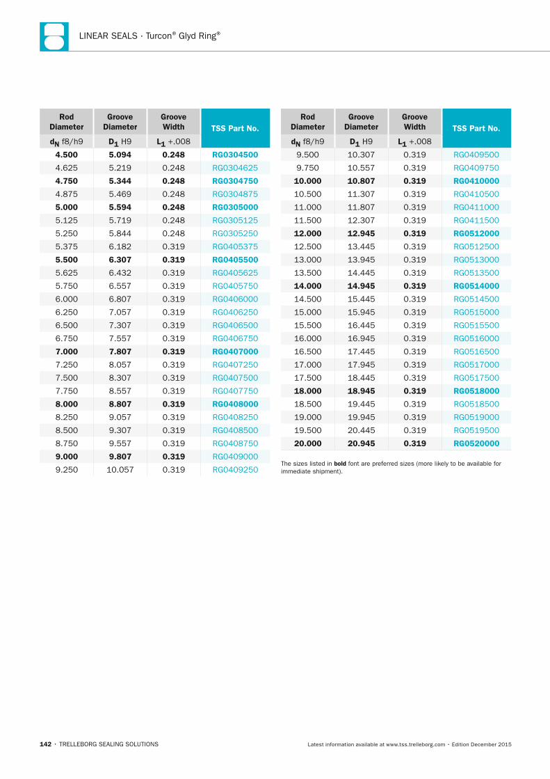
LINEAR SEALS · Turcon® Glyd Ring®
142 • TRELLEBORG SEALING SOLUTIONS Latest information available at www.tss.trelleborg.com • Edition December 2015
Rod Diameter
Groove Diameter
Groove Width TSS Part no.
dn f8/h9 D1 H9 L1 +.008
4.500 5.094 0.248 RG0304500
4.625 5.219 0.248 RG0304625
4.750 5.344 0.248 RG0304750
4.875 5.469 0.248 RG0304875
5.000 5.594 0.248 RG0305000
5.125 5.719 0.248 RG0305125
5.250 5.844 0.248 RG0305250
5.375 6.182 0.319 RG0405375
5.500 6.307 0.319 RG0405500
5.625 6.432 0.319 RG0405625
5.750 6.557 0.319 RG0405750
6.000 6.807 0.319 RG0406000
6.250 7.057 0.319 RG0406250
6.500 7.307 0.319 RG0406500
6.750 7.557 0.319 RG0406750
7.000 7.807 0.319 RG0407000
7.250 8.057 0.319 RG0407250
7.500 8.307 0.319 RG0407500
7.750 8.557 0.319 RG0407750
8.000 8.807 0.319 RG0408000
8.250 9.057 0.319 RG0408250
8.500 9.307 0.319 RG0408500
8.750 9.557 0.319 RG0408750
9.000 9.807 0.319 RG0409000
9.250 10.057 0.319 RG0409250
Rod Diameter
Groove Diameter
Groove Width TSS Part no.
dn f8/h9 D1 H9 L1 +.008
9.500 10.307 0.319 RG0409500
9.750 10.557 0.319 RG0409750
10.000 10.807 0.319 RG0410000
10.500 11.307 0.319 RG0410500
11.000 11.807 0.319 RG0411000
11.500 12.307 0.319 RG0411500
12.000 12.945 0.319 RG0512000
12.500 13.445 0.319 RG0512500
13.000 13.945 0.319 RG0513000
13.500 14.445 0.319 RG0513500
14.000 14.945 0.319 RG0514000
14.500 15.445 0.319 RG0514500
15.000 15.945 0.319 RG0515000
15.500 16.445 0.319 RG0515500
16.000 16.945 0.319 RG0516000
16.500 17.445 0.319 RG0516500
17.000 17.945 0.319 RG0517000
17.500 18.445 0.319 RG0517500
18.000 18.945 0.319 RG0518000
18.500 19.445 0.319 RG0518500
19.000 19.945 0.319 RG0519000
19.500 20.445 0.319 RG0519500
20.000 20.945 0.319 RG0520000
The sizes listed in bold font are preferred sizes (more likely to be available for immediate shipment).
FBP_neues_Layout_2015.indb 142 17.10.2016 13:36:31

Turcon® Glyd Ring®
TRELLEBORG SEALING SOLUTIONS • 143Latest information available at www.tss.trelleborg.com • Edition December 2015
FBP_neues_Layout_2015.indb 143 17.10.2016 13:36:31
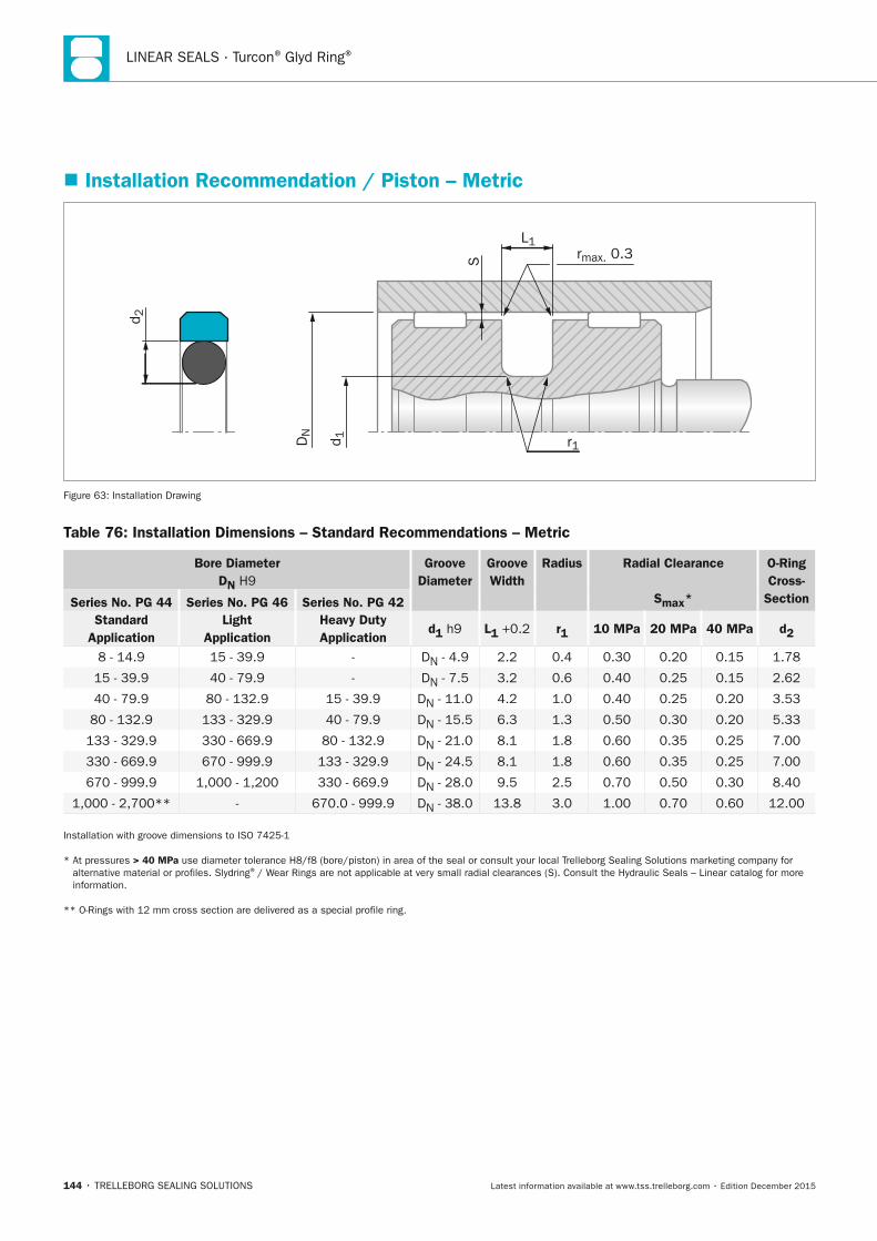
LINEAR SEALS · Turcon® Glyd Ring®
144 • TRELLEBORG SEALING SOLUTIONS Latest information available at www.tss.trelleborg.com • Edition December 2015
� Installation Recommendation / Piston – Metric
S
L1rmax. 0.3
r1
d 2
DN
d 1
Figure 63: Installation Drawing
Table 76: Installation Dimensions – Standard Recommendations – Metric
Bore Diameter Dn H9
Groove Diameter
Groove Width
Radius Radial Clearance
Smax*
O-Ring Cross-
SectionSeries no. PG 44 Series no. PG 46 Series no. PG 42 Standard
Application Light
Application Heavy Duty Application
d1 h9 L1 +0.2 r1 10 MPa 20 MPa 40 MPa d2
8 - 14.9 15 - 39.9 - DN - 4.9 2.2 0.4 0.30 0.20 0.15 1.78
15 - 39.9 40 - 79.9 - DN - 7.5 3.2 0.6 0.40 0.25 0.15 2.62
40 - 79.9 80 - 132.9 15 - 39.9 DN - 11.0 4.2 1.0 0.40 0.25 0.20 3.53
80 - 132.9 133 - 329.9 40 - 79.9 DN - 15.5 6.3 1.3 0.50 0.30 0.20 5.33
133 - 329.9 330 - 669.9 80 - 132.9 DN - 21.0 8.1 1.8 0.60 0.35 0.25 7.00
330 - 669.9 670 - 999.9 133 - 329.9 DN - 24.5 8.1 1.8 0.60 0.35 0.25 7.00
670 - 999.9 1,000 - 1,200 330 - 669.9 DN - 28.0 9.5 2.5 0.70 0.50 0.30 8.40
1,000 - 2,700** - 670.0 - 999.9 DN - 38.0 13.8 3.0 1.00 0.70 0.60 12.00
Installation with groove dimensions to ISO 7425-1
* At pressures > 40 MPa use diameter tolerance H8/f8 (bore/piston) in area of the seal or consult your local Trelleborg Sealing Solutions marketing company for alternative material or profiles. Slydring® / Wear Rings are not applicable at very small radial clearances (S). Consult the Hydraulic Seals – Linear catalog for more information.
** O-Rings with 12 mm cross section are delivered as a special profile ring.
FBP_neues_Layout_2015.indb 144 17.10.2016 13:36:32
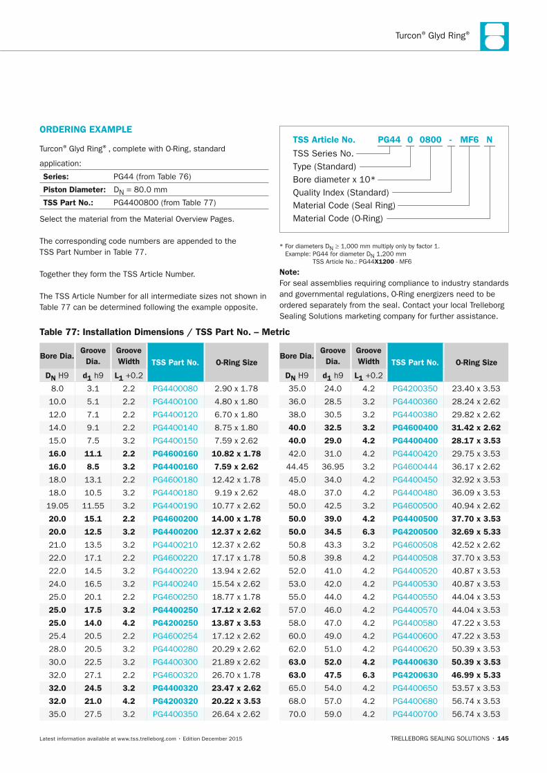
Turcon® Glyd Ring®
TRELLEBORG SEALING SOLUTIONS • 145Latest information available at www.tss.trelleborg.com • Edition December 2015
ORDERInG ExAMPLE
Turcon® Glyd Ring®, complete with O-Ring, standard
application:
Series: PG44 (from Table 76)
Piston Diameter: DN = 80.0 mm
TSS Part no.: PG4400800 (from Table 77)
Select the material from the Material Overview Pages.
The corresponding code numbers are appended to the TSS Part Number in Table 77.
Together they form the TSS Article Number.
The TSS Article Number for all intermediate sizes not shown in Table 77 can be determined following the example opposite.
Material Code (Seal Ring)
TSS Series No.
TSS Article No.
Material Code (O-Ring)
Bore diameter x 10*Quality Index (Standard)
Type (Standard)
MF6 NPG44 -0 0800
* For diameters DN ≥ 1,000 mm multiply only by factor 1. Example: PG44 for diameter DN 1,200 mm
TSS Article No.: PG44x1200 - MF6
note:For seal assemblies requiring compliance to industry standards and governmental regulations, O-Ring energizers need to be ordered separately from the seal. Contact your local Trelleborg Sealing Solutions marketing company for further assistance.
Table 77: Installation Dimensions / TSS Part no. – Metric
Bore Dia. Groove
Dia. Groove Width TSS Part no. O-Ring Size
Dn H9 d1 h9 L1 +0.2
8.0 3.1 2.2 PG4400080 2.90 x 1.78
10.0 5.1 2.2 PG4400100 4.80 x 1.80
12.0 7.1 2.2 PG4400120 6.70 x 1.80
14.0 9.1 2.2 PG4400140 8.75 x 1.80
15.0 7.5 3.2 PG4400150 7.59 x 2.62
16.0 11.1 2.2 PG4600160 10.82 x 1.78
16.0 8.5 3.2 PG4400160 7.59 x 2.62
18.0 13.1 2.2 PG4600180 12.42 x 1.78
18.0 10.5 3.2 PG4400180 9.19 x 2.62
19.05 11.55 3.2 PG4400190 10.77 x 2.62
20.0 15.1 2.2 PG4600200 14.00 x 1.78
20.0 12.5 3.2 PG4400200 12.37 x 2.62
21.0 13.5 3.2 PG4400210 12.37 x 2.62
22.0 17.1 2.2 PG4600220 17.17 x 1.78
22.0 14.5 3.2 PG4400220 13.94 x 2.62
24.0 16.5 3.2 PG4400240 15.54 x 2.62
25.0 20.1 2.2 PG4600250 18.77 x 1.78
25.0 17.5 3.2 PG4400250 17.12 x 2.62
25.0 14.0 4.2 PG4200250 13.87 x 3.53
25.4 20.5 2.2 PG4600254 17.12 x 2.62
28.0 20.5 3.2 PG4400280 20.29 x 2.62
30.0 22.5 3.2 PG4400300 21.89 x 2.62
32.0 27.1 2.2 PG4600320 26.70 x 1.78
32.0 24.5 3.2 PG4400320 23.47 x 2.62
32.0 21.0 4.2 PG4200320 20.22 x 3.53
35.0 27.5 3.2 PG4400350 26.64 x 2.62
Bore Dia. Groove
Dia. Groove Width TSS Part no. O-Ring Size
Dn H9 d1 h9 L1 +0.2
35.0 24.0 4.2 PG4200350 23.40 x 3.53
36.0 28.5 3.2 PG4400360 28.24 x 2.62
38.0 30.5 3.2 PG4400380 29.82 x 2.62
40.0 32.5 3.2 PG4600400 31.42 x 2.62
40.0 29.0 4.2 PG4400400 28.17 x 3.53
42.0 31.0 4.2 PG4400420 29.75 x 3.53
44.45 36.95 3.2 PG4600444 36.17 x 2.62
45.0 34.0 4.2 PG4400450 32.92 x 3.53
48.0 37.0 4.2 PG4400480 36.09 x 3.53
50.0 42.5 3.2 PG4600500 40.94 x 2.62
50.0 39.0 4.2 PG4400500 37.70 x 3.53
50.0 34.5 6.3 PG4200500 32.69 x 5.33
50.8 43.3 3.2 PG4600508 42.52 x 2.62
50.8 39.8 4.2 PG4400508 37.70 x 3.53
52.0 41.0 4.2 PG4400520 40.87 x 3.53
53.0 42.0 4.2 PG4400530 40.87 x 3.53
55.0 44.0 4.2 PG4400550 44.04 x 3.53
57.0 46.0 4.2 PG4400570 44.04 x 3.53
58.0 47.0 4.2 PG4400580 47.22 x 3.53
60.0 49.0 4.2 PG4400600 47.22 x 3.53
62.0 51.0 4.2 PG4400620 50.39 x 3.53
63.0 52.0 4.2 PG4400630 50.39 x 3.53
63.0 47.5 6.3 PG4200630 46.99 x 5.33
65.0 54.0 4.2 PG4400650 53.57 x 3.53
68.0 57.0 4.2 PG4400680 56.74 x 3.53
70.0 59.0 4.2 PG4400700 56.74 x 3.53
FBP_neues_Layout_2015.indb 145 17.10.2016 13:36:32
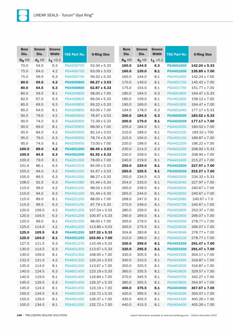
LINEAR SEALS · Turcon® Glyd Ring®
146 • TRELLEBORG SEALING SOLUTIONS Latest information available at www.tss.trelleborg.com • Edition December 2015
Bore Dia.
Groove Dia.
Groove Width TSS Part no. O-Ring SIze
Dn H9 d1 h9 L1 +0.2
70.0 54.5 6.3 PG4200700 53.34 x 5.33
75.0 64.0 4.2 PG4400750 63.09 x 3.53
75.0 59.5 6.3 PG4200750 56.52 x 5.33
80.0 69.0 4.2 PG4600800 66.27 x 3.53
80.0 64.5 6.3 PG4400800 62.87 x 5.33
80.0 59.0 8.1 PG4200800 58.00 x 7.00
82.5 67.0 6.3 PG4400825 66.04 x 5.33
85.0 69.5 6.3 PG4400850 69.22 x 5.33
85.0 64.0 8.1 PG4200850 63.00 x 7.00
90.0 79.0 4.2 PG4600900 78.97 x 3.53
90.0 74.5 6.3 PG4400900 72.39 x 5.33
90.0 69.0 8.1 PG4200900 68.00 x 7.00
95.0 84.0 4.2 PG4600950 82.14 x 3.53
95.0 79.5 6.3 PG4400950 78.74 x 5.33
95.0 74.0 8.1 PG4200950 73.00 x 7.00
100.0 89.0 4.2 PG4601000 88.49 x 3.53
100.0 84.5 6.3 PG4401000 81.92 x 5.33
100.0 79.0 8.1 PG4201000 78.00 x 7.00
101.6 86.1 6.3 PG4401016 85.09 x 5.33
105.0 94.0 4.2 PG4601050 91.67 x 3.53
105.0 89.5 6.3 PG4401050 88.27 x 5.33
108.0 92.5 6.3 PG4401080 91.44 x 5.33
110.0 99.0 4.2 PG4601100 98.02 x 3.53
110.0 94.5 6.3 PG4401100 91.44 x 5.33
110.0 89.0 8.1 PG4201100 88.00 x 7.00
115.0 99.5 6.3 PG4401150 97.79 x 5.33
120.0 109.0 4.2 PG4601200 107.54 x 3.53
120.0 104.5 6.3 PG4401200 100.97 x 5.33
120.0 99.0 8.1 PG4201200 98.00 x 7.00
125.0 114.0 4.2 PG4601250 113.89 x 3.53
125.0 109.5 6.3 PG4401250 107.32 x 5.33
125.0 104.0 8.1 PG4201250 103.00 x 7.00
127.0 111.5 6.3 PG4401270 110.49 x 5.33
130.0 114.5 6.3 PG4401300 113.67 x 5.33
130.0 109.0 8.1 PG4201300 108.00 x 7.00
132.0 121.0 4.2 PG4601320 120.24 x 3.53
135.0 114.0 8.1 PG4401350 113.67 x 7.00
140.0 124.5 6.3 PG4601400 123.19 x 5.33
140.0 119.0 8.1 PG4401400 116.84 x 7.00
145.0 129.5 6.3 PG4601450 126.37 x 5.33
145.0 124.0 8.1 PG4401450 123.19 x 7.00
150.0 134.5 6.3 PG4601500 132.72 x 5.33
150.0 129.0 8.1 PG4401500 126.37 x 7.00
155.0 134.0 8.1 PG4401550 132.72 x 7.00
Bore Dia.
Groove Dia.
Groove Width TSS Part no. O-Ring SIze
Dn H9 d1 h9 L1 +0.2
160.0 144.5 6.3 PG4601600 142.24 x 5.33
160.0 139.0 8.1 PG4401600 135.89 x 7.00
165.0 144.0 8.1 PG4401650 142.24 x 7.00
170.0 149.0 8.1 PG4401700 145.42 x 7.00
175.0 154.0 8.1 PG4401750 151.77 x 7.00
180.0 164.5 6.3 PG4601800 164.47 x 5.33
180.0 159.0 8.1 PG4401800 158.12 x 7.00
190.0 169.0 8.1 PG4401900 164.47 x 7.00
194.0 178.5 6.3 PG4601940 177.17 x 5.33
200.0 184.5 6.3 PG4602000 183.52 x 5.33
200.0 179.0 8.1 PG4402000 177.17 x 7.00
205.0 184.0 8.1 PG4402050 183.52 x 7.00
210.0 189.0 8.1 PG4402100 183.52 x 700
215.0 194.0 8.1 PG4402150 189.87 x 7.00
220.0 199.0 8.1 PG4402200 196.22 x 7.00
230.0 214.5 6.3 PG4602300 208.92 x 5.33
230.0 209.0 8.1 PG4402300 208.90 x 7.00
240.0 219.0 8.1 PG4402400 215.27 x 7.00
250.0 229.0 8.1 PG4402500 227.97 x 7.00
250.0 225.5 8.1 PG4202500 215.27 x 7.00
250.0 234.5 6.3 PG4602500 234.32 x 5.33
254.0 233.0 8.1 PG4402540 227.97 x 7.00
260.0 239.0 8.1 PG4402600 240.67 x 7.00
265.0 244.0 8.1 PG4402650 240.67 x 7.00
268.0 247.0 8.1 PG4402680 240.67 x 7.0
270.0 249.0 8.1 PG4402700 240.67 x 7.00
280.0 259.0 8.1 PG4402800 253.37 x 7.00
290.0 269.0 8.1 PG4402900 266.07 x 7.00
300.0 279.0 8.1 PG4403000 278.77 x 7.00
300.0 275.5 8.1 PG4203000 266.07 x 7.00
304.8 283.8 8.1 PG4403048 278.77 x 7.00
310.0 289.0 8.1 PG4403100 278.77 x 7.00
320.0 299.0 8.1 PG4403200 291.47 x 7.00
320.0 295.5 8.1 PG4203200 291.47 x 7.00
330.0 305.5 8.1 PG4403300 304.17 x 7.00
340.0 315.5 8.1 PG4403400 316.87 x 7.00
350.0 325.5 8.1 PG4403500 316.87 x 7.00
360.0 335.5 8.1 PG4403600 329.57 x 7.00
370.0 345.5 8.1 PG4403700 342.27 x 7.00
380.0 355.5 8.1 PG4403800 354.97 x 7.00
400.0 375.5 8.1 PG4404000 367.67 x 7.00
420.0 395.5 8.1 PG4404200 393.07 x 7.00
430.0 405.5 8.1 PG4404300 405.26 x 7.00
440.0 415.5 8.1 PG4404400 405.26 x 7.00
FBP_neues_Layout_2015.indb 146 17.10.2016 13:36:33
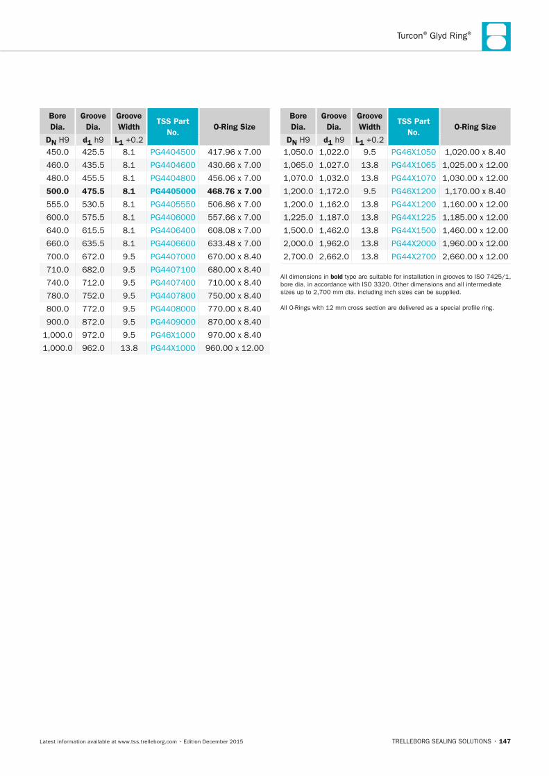
Turcon® Glyd Ring®
TRELLEBORG SEALING SOLUTIONS • 147Latest information available at www.tss.trelleborg.com • Edition December 2015
Bore Dia.
Groove Dia.
Groove Width
TSS Part no.
O-Ring Size
Dn H9 d1 h9 L1 +0.2 450.0 425.5 8.1 PG4404500 417.96 x 7.00
460.0 435.5 8.1 PG4404600 430.66 x 7.00
480.0 455.5 8.1 PG4404800 456.06 x 7.00
500.0 475.5 8.1 PG4405000 468.76 x 7.00
555.0 530.5 8.1 PG4405550 506.86 x 7.00
600.0 575.5 8.1 PG4406000 557.66 x 7.00
640.0 615.5 8.1 PG4406400 608.08 x 7.00
660.0 635.5 8.1 PG4406600 633.48 x 7.00
700.0 672.0 9.5 PG4407000 670.00 x 8.40
710.0 682.0 9.5 PG4407100 680.00 x 8.40
740.0 712.0 9.5 PG4407400 710.00 x 8.40
780.0 752.0 9.5 PG4407800 750.00 x 8.40
800.0 772.0 9.5 PG4408000 770.00 x 8.40
900.0 872.0 9.5 PG4409000 870.00 x 8.40
1,000.0 972.0 9.5 PG46X1000 970.00 x 8.40
1,000.0 962.0 13.8 PG44X1000 960.00 x 12.00
Bore Dia.
Groove Dia.
Groove Width
TSS Part no.
O-Ring Size
Dn H9 d1 h9 L1 +0.2 1,050.0 1,022.0 9.5 PG46X1050 1,020.00 x 8.40
1,065.0 1,027.0 13.8 PG44X1065 1,025.00 x 12.00
1,070.0 1,032.0 13.8 PG44X1070 1,030.00 x 12.00
1,200.0 1,172.0 9.5 PG46X1200 1,170.00 x 8.40
1,200.0 1,162.0 13.8 PG44X1200 1,160.00 x 12.00
1,225.0 1,187.0 13.8 PG44X1225 1,185.00 x 12.00
1,500.0 1,462.0 13.8 PG44X1500 1,460.00 x 12.00
2,000.0 1,962.0 13.8 PG44X2000 1,960.00 x 12.00
2,700.0 2,662.0 13.8 PG44X2700 2,660.00 x 12.00
All dimensions in bold type are suitable for installation in grooves to ISO 7425/1, bore dia. in accordance with ISO 3320. Other dimensions and all intermediate sizes up to 2,700 mm dia. including inch sizes can be supplied.
All O-Rings with 12 mm cross section are delivered as a special profile ring.
FBP_neues_Layout_2015.indb 147 17.10.2016 13:36:33
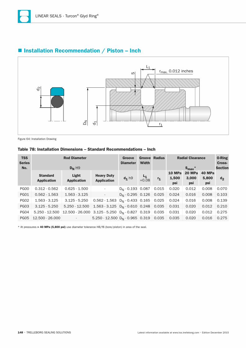
LINEAR SEALS · Turcon® Glyd Ring®
148 • TRELLEBORG SEALING SOLUTIONS Latest information available at www.tss.trelleborg.com • Edition December 2015
� Installation Recommendation / Piston – Inch
S
L1
r1
d 2
DN
d 1
rmax. 0.012 inches
Figure 64: Installation Drawing
Table 78: Installation Dimensions – Standard Recommendations – Inch
TSS Series
no.
Rod Diameter
Dn H9
Groove Diameter
Groove Width
Radius Radial Clearance
Smax*
O-Ring Cross-
Section
Standard Application
Light Application
Heavy Duty Application
d1 h9 L1
+0.08 r1
10 MPa 1,500
psi
20 MPa 3,000
psi
40 MPa 5,800
psi d2
PG00 0.312 - 0.562 0.625 - 1.500 - DN - 0.193 0.087 0.015 0.020 0.012 0.008 0.070
PG01 0.562 - 1.563 1.563 - 3.125 - DN - 0.295 0.126 0.025 0.024 0.016 0.008 0.103
PG02 1.563 - 3.125 3.125 - 5.250 0.562 - 1.563 DN - 0.433 0.165 0.025 0.024 0.016 0.008 0.139
PG03 3.125 - 5.250 5.250 - 12.500 1.563 - 3.125 DN - 0.610 0.248 0.035 0.031 0.020 0.012 0.210
PG04 5.250 - 12.500 12.500 - 26.000 3.125 - 5.250 DN - 0.827 0.319 0.035 0.031 0.020 0.012 0.275
PG05 12.500 - 26.000 - 5.250 - 12.500 DN - 0.965 0.319 0.035 0.035 0.020 0.016 0.275
* At pressures > 40 MPa (5,800 psi) use diameter tolerance H8/f8 (bore/piston) in area of the seal.
FBP_neues_Layout_2015.indb 148 17.10.2016 13:36:34
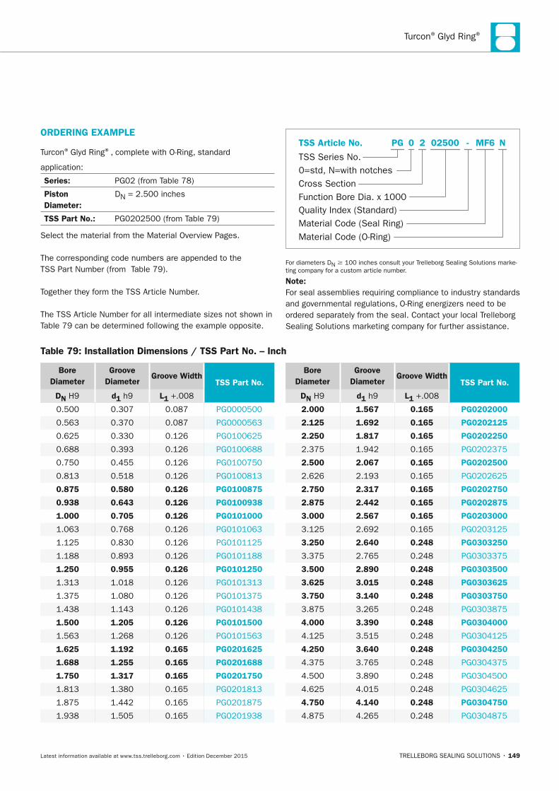
Turcon® Glyd Ring®
TRELLEBORG SEALING SOLUTIONS • 149Latest information available at www.tss.trelleborg.com • Edition December 2015
ORDERInG ExAMPLE
Turcon® Glyd Ring®, complete with O-Ring, standard
application:
Series: PG02 (from Table 78)
Piston Diameter:
DN = 2.500 inches
TSS Part no.: PG0202500 (from Table 79)
Select the material from the Material Overview Pages.
The corresponding code numbers are appended to the TSS Part Number (from Table 79).
Together they form the TSS Article Number.
The TSS Article Number for all intermediate sizes not shown in Table 79 can be determined following the example opposite.
Quality Index (Standard)
TSS Series No.
TSS Article No.
Material Code (Seal Ring)Material Code (O-Ring)
Cross SectionFunction Bore Dia. x 1000
0=std, N=with notches
-2 MF6PG 02500 N0
For diameters DN 100 inches consult your Trelleborg Sealing Solutions marke-ting company for a custom article number.
note:For seal assemblies requiring compliance to industry standards and governmental regulations, O-Ring energizers need to be ordered separately from the seal. Contact your local Trelleborg Sealing Solutions marketing company for further assistance.
Table 79: Installation Dimensions / TSS Part no. – Inch
Bore Diameter
Groove Diameter
Groove Width TSS Part no.
Dn H9 d1 h9 L1 +.008
0.500 0.307 0.087 PG0000500
0.563 0.370 0.087 PG0000563
0.625 0.330 0.126 PG0100625
0.688 0.393 0.126 PG0100688
0.750 0.455 0.126 PG0100750
0.813 0.518 0.126 PG0100813
0.875 0.580 0.126 PG0100875
0.938 0.643 0.126 PG0100938
1.000 0.705 0.126 PG0101000
1.063 0.768 0.126 PG0101063
1.125 0.830 0.126 PG0101125
1.188 0.893 0.126 PG0101188
1.250 0.955 0.126 PG0101250
1.313 1.018 0.126 PG0101313
1.375 1.080 0.126 PG0101375
1.438 1.143 0.126 PG0101438
1.500 1.205 0.126 PG0101500
1.563 1.268 0.126 PG0101563
1.625 1.192 0.165 PG0201625
1.688 1.255 0.165 PG0201688
1.750 1.317 0.165 PG0201750
1.813 1.380 0.165 PG0201813
1.875 1.442 0.165 PG0201875
1.938 1.505 0.165 PG0201938
Bore Diameter
Groove Diameter
Groove Width TSS Part no.
Dn H9 d1 h9 L1 +.008
2.000 1.567 0.165 PG0202000
2.125 1.692 0.165 PG0202125
2.250 1.817 0.165 PG0202250
2.375 1.942 0.165 PG0202375
2.500 2.067 0.165 PG0202500
2.626 2.193 0.165 PG0202625
2.750 2.317 0.165 PG0202750
2.875 2.442 0.165 PG0202875
3.000 2.567 0.165 PG0203000
3.125 2.692 0.165 PG0203125
3.250 2.640 0.248 PG0303250
3.375 2.765 0.248 PG0303375
3.500 2.890 0.248 PG0303500
3.625 3.015 0.248 PG0303625
3.750 3.140 0.248 PG0303750
3.875 3.265 0.248 PG0303875
4.000 3.390 0.248 PG0304000
4.125 3.515 0.248 PG0304125
4.250 3.640 0.248 PG0304250
4.375 3.765 0.248 PG0304375
4.500 3.890 0.248 PG0304500
4.625 4.015 0.248 PG0304625
4.750 4.140 0.248 PG0304750
4.875 4.265 0.248 PG0304875
FBP_neues_Layout_2015.indb 149 17.10.2016 13:36:34
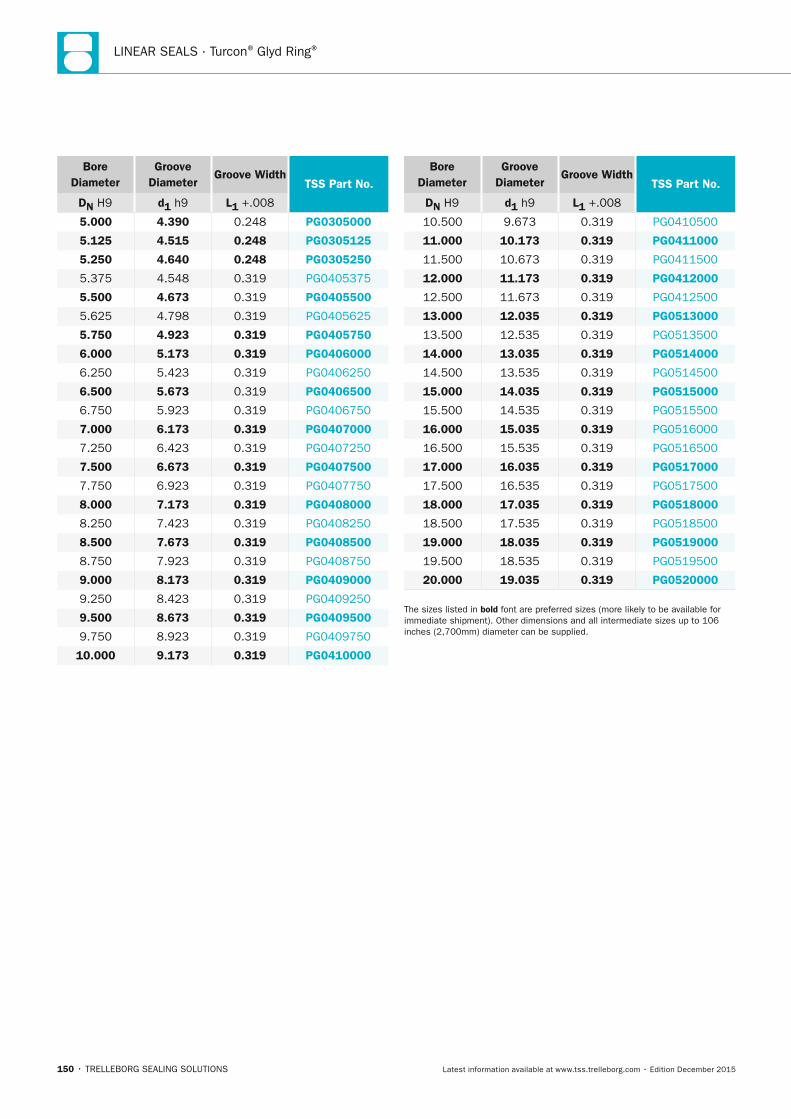
LINEAR SEALS · Turcon® Glyd Ring®
150 • TRELLEBORG SEALING SOLUTIONS Latest information available at www.tss.trelleborg.com • Edition December 2015
Bore Diameter
Groove Diameter
Groove Width TSS Part no.
Dn H9 d1 h9 L1 +.008
5.000 4.390 0.248 PG0305000
5.125 4.515 0.248 PG0305125
5.250 4.640 0.248 PG0305250
5.375 4.548 0.319 PG0405375
5.500 4.673 0.319 PG0405500
5.625 4.798 0.319 PG0405625
5.750 4.923 0.319 PG0405750
6.000 5.173 0.319 PG0406000
6.250 5.423 0.319 PG0406250
6.500 5.673 0.319 PG0406500
6.750 5.923 0.319 PG0406750
7.000 6.173 0.319 PG0407000
7.250 6.423 0.319 PG0407250
7.500 6.673 0.319 PG0407500
7.750 6.923 0.319 PG0407750
8.000 7.173 0.319 PG0408000
8.250 7.423 0.319 PG0408250
8.500 7.673 0.319 PG0408500
8.750 7.923 0.319 PG0408750
9.000 8.173 0.319 PG0409000
9.250 8.423 0.319 PG0409250
9.500 8.673 0.319 PG0409500
9.750 8.923 0.319 PG0409750
10.000 9.173 0.319 PG0410000
Bore Diameter
Groove Diameter
Groove Width TSS Part no.
Dn H9 d1 h9 L1 +.008
10.500 9.673 0.319 PG0410500
11.000 10.173 0.319 PG0411000
11.500 10.673 0.319 PG0411500
12.000 11.173 0.319 PG0412000
12.500 11.673 0.319 PG0412500
13.000 12.035 0.319 PG0513000
13.500 12.535 0.319 PG0513500
14.000 13.035 0.319 PG0514000
14.500 13.535 0.319 PG0514500
15.000 14.035 0.319 PG0515000
15.500 14.535 0.319 PG0515500
16.000 15.035 0.319 PG0516000
16.500 15.535 0.319 PG0516500
17.000 16.035 0.319 PG0517000
17.500 16.535 0.319 PG0517500
18.000 17.035 0.319 PG0518000
18.500 17.535 0.319 PG0518500
19.000 18.035 0.319 PG0519000
19.500 18.535 0.319 PG0519500
20.000 19.035 0.319 PG0520000
The sizes listed in bold font are preferred sizes (more likely to be available for immediate shipment). Other dimensions and all intermediate sizes up to 106 inches (2,700mm) diameter can be supplied.
FBP_neues_Layout_2015.indb 150 17.10.2016 13:36:35
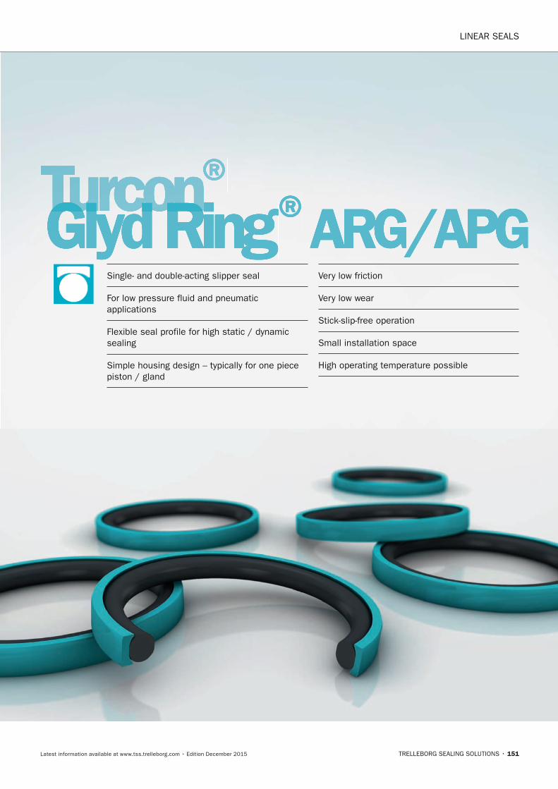
LINEAR SEALS
TRELLEBORG SEALING SOLUTIONS • 151Latest information available at www.tss.trelleborg.com • Edition December 2015
Turcon® Turcon® TurconGlyd RingTurconGlyd RingTurcon ® ARG/APGSingle- and double-acting slipper seal
For low pressure fluid and pneumatic applications
Flexible seal profile for high static / dynamic sealing
Simple housing design – typically for one piece piston / gland
Very low friction
Very low wear
Stick-slip-free operation
Small installation space
High operating temperature possible
FBP_neues_Layout_2015.indb 151 17.10.2016 13:36:37

LINEAR SEALS · Turcon® Glyd Ring® ARG / APG
152 • TRELLEBORG SEALING SOLUTIONS Latest information available at www.tss.trelleborg.com • Edition December 2015
FBP_neues_Layout_2015.indb 152 17.10.2016 13:36:37
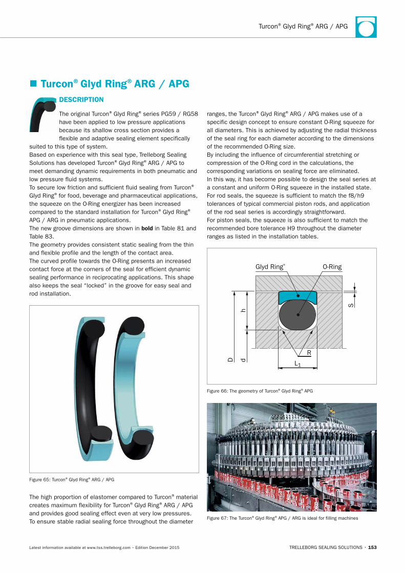
Turcon® Glyd Ring® ARG / APG
TRELLEBORG SEALING SOLUTIONS • 153Latest information available at www.tss.trelleborg.com • Edition December 2015
DESCRIPTIOn
The original Turcon® Glyd Ring® series PG59 / RG58 have been applied to low pressure applications because its shallow cross section provides a flexible and adaptive sealing element specifically
suited to this type of system.Based on experience with this seal type, Trelleborg Sealing Solutions has developed Turcon® Glyd Ring® ARG / APG to meet demanding dynamic requirements in both pneumatic and low pressure fluid systems.To secure low friction and sufficient fluid sealing from Turcon®
Glyd Ring® for food, beverage and pharmaceutical applications, the squeeze on the O-Ring energizer has been increased compared to the standard installation for Turcon® Glyd Ring®
APG / ARG in pneumatic applications.The new groove dimensions are shown in bold in Table 81 and Table 83.The geometry provides consistent static sealing from the thin and flexible profile and the length of the contact area.The curved profile towards the O-Ring presents an increased contact force at the corners of the seal for efficient dynamic sealing performance in reciprocating applications. This shape also keeps the seal “locked” in the groove for easy seal and rod installation.
Figure 65: Turcon® Glyd Ring® ARG / APG
The high proportion of elastomer compared to Turcon® material creates maximum flexibility for Turcon® Glyd Ring® ARG / APG and provides good sealing effect even at very low pressures.To ensure stable radial sealing force throughout the diameter
ranges, the Turcon® Glyd Ring® ARG / APG makes use of a specific design concept to ensure constant O-Ring squeeze for all diameters. This is achieved by adjusting the radial thickness of the seal ring for each diameter according to the dimensions of the recommended O-Ring size.By including the influence of circumferential stretching or compression of the O-Ring cord in the calculations, the corresponding variations on sealing force are eliminated. In this way, it has become possible to design the seal series at a constant and uniform O-Ring squeeze in the installed state.For rod seals, the squeeze is sufficient to match the f8/h9 tolerances of typical commercial piston rods, and application of the rod seal series is accordingly straightforward.For piston seals, the squeeze is also sufficient to match the recommended bore tolerance H9 throughout the diameter ranges as listed in the installation tables.
O-RingGlyd Ring®
SR
h
D d L1
Figure 66: The geometry of Turcon® Glyd Ring® APG
Figure 67: The Turcon® Glyd Ring® APG / ARG is ideal for filling machines
� Turcon®Glyd Ring®ARG / APG
FBP_neues_Layout_2015.indb 153 17.10.2016 13:36:40
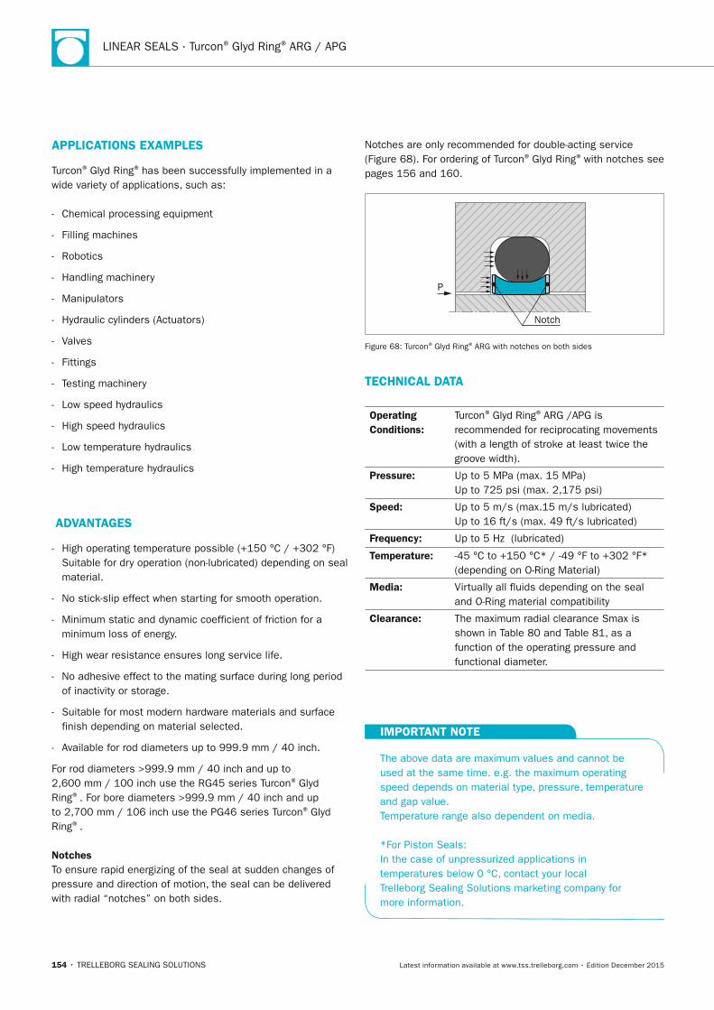
LINEAR SEALS · Turcon® Glyd Ring® ARG / APG
154 • TRELLEBORG SEALING SOLUTIONS Latest information available at www.tss.trelleborg.com • Edition December 2015
APPLICATIOnS ExAMPLES
Turcon® Glyd Ring® has been successfully implemented in a wide variety of applications, such as:
- Chemical processing equipment
- Filling machines
- Robotics
- Handling machinery
- Manipulators
- Hydraulic cylinders (Actuators)
- Valves
- Fittings
- Testing machinery
- Low speed hydraulics
- High speed hydraulics
- Low temperature hydraulics
- High temperature hydraulics
ADVAnTAGES
- High operating temperature possible (+150 °C / +302 °F) Suitable for dry operation (non-lubricated) depending on seal material.
- No stick-slip effect when starting for smooth operation.
- Minimum static and dynamic coefficient of friction for a minimum loss of energy.
- High wear resistance ensures long service life.
- No adhesive effect to the mating surface during long period of inactivity or storage.
- Suitable for most modern hardware materials and surface finish depending on material selected.
- Available for rod diameters up to 999.9 mm / 40 inch.
For rod diameters >999.9 mm / 40 inch and up to 2,600 mm / 100 inch use the RG45 series Turcon® Glyd Ring®. For bore diameters >999.9 mm / 40 inch and up to 2,700 mm / 106 inch use the PG46 series Turcon® Glyd Ring®.
notchesTo ensure rapid energizing of the seal at sudden changes of pressure and direction of motion, the seal can be delivered with radial “notches” on both sides.
Notches are only recommended for double-acting service (Figure 68). For ordering of Turcon® Glyd Ring® with notches see pages 156 and 160.
P
Notch
Figure 68: Turcon® Glyd Ring® ARG with notches on both sides
TECHnICAL DATA
Operating Conditions:
Turcon® Glyd Ring® ARG /APG is recommended for reciprocating movements (with a length of stroke at least twice the groove width).
Pressure: Up to 5 MPa (max. 15 MPa)Up to 725 psi (max. 2,175 psi)
Speed: Up to 5 m/s (max.15 m/s lubricated)Up to 16 ft/s (max. 49 ft/s lubricated)
Frequency: Up to 5 Hz (lubricated)
Temperature: -45 °C to +150 °C* / -49 °F to +302 °F* (depending on O-Ring Material)
Media: Virtually all fluids depending on the seal and O-Ring material compatibility
Clearance: The maximum radial clearance Smax is shown in Table 80 and Table 81, as a function of the operating pressure and functional diameter.
IMPORTAnT nOTE
The above data are maximum values and cannot be used at the same time. e.g. the maximum operating speed depends on material type, pressure, temperature and gap value. Temperature range also dependent on media.
*For Piston Seals:In the case of unpressurized applications in temperatures below 0 °C, contact your local Trelleborg Sealing Solutions marketing company for more information.
FBP_neues_Layout_2015.indb 154 17.10.2016 13:36:41
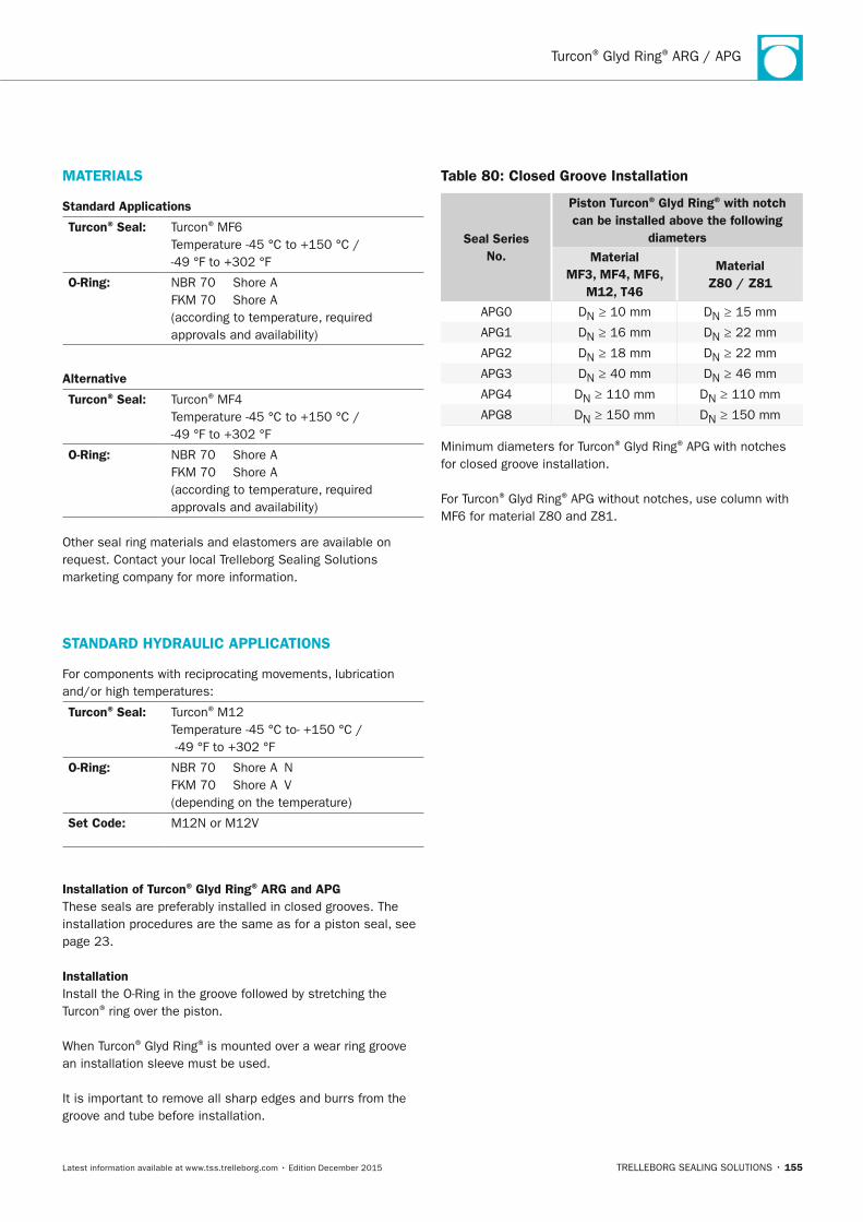
Turcon® Glyd Ring® ARG / APG
TRELLEBORG SEALING SOLUTIONS • 155Latest information available at www.tss.trelleborg.com • Edition December 2015
MATERIALS
Standard Applications
Turcon® Seal: Turcon® MF6 Temperature -45 °C to +150 °C / -49 °F to +302 °F
O-Ring: NBR 70 Shore A FKM 70 Shore A (according to temperature, required approvals and availability)
Alternative
Turcon® Seal: Turcon® MF4 Temperature -45 °C to +150 °C / -49 °F to +302 °F
O-Ring: NBR 70 Shore A FKM 70 Shore A (according to temperature, required approvals and availability)
Other seal ring materials and elastomers are available on request. Contact your local Trelleborg Sealing Solutions marketing company for more information.
STAnDARD HyDRAULIC APPLICATIOnS
For components with reciprocating movements, lubrication and/or high temperatures:
Turcon® Seal: Turcon® M12 Temperature -45 °C to- +150 °C / -49 °F to +302 °F
O-Ring: NBR 70 Shore A N FKM 70 Shore A V (depending on the temperature)
Set Code: M12N or M12V
Installation of Turcon® Glyd Ring® ARG and APGThese seals are preferably installed in closed grooves. The installation procedures are the same as for a piston seal, see page 23.
InstallationInstall the O-Ring in the groove followed by stretching the Turcon® ring over the piston.
When Turcon® Glyd Ring® is mounted over a wear ring groove an installation sleeve must be used.
It is important to remove all sharp edges and burrs from the groove and tube before installation.
Table 80: Closed Groove Installation
Seal Series no.
Piston Turcon® Glyd Ring® with notch can be installed above the following
diametersMaterial
MF3, MF4, MF6, M12, T46
Material Z80 / Z81
APG0 DN ≥ 10 mm DN ≥ 15 mm
APG1 DN ≥ 16 mm DN ≥ 22 mm
APG2 DN ≥ 18 mm DN ≥ 22 mm
APG3 DN ≥ 40 mm DN ≥ 46 mm
APG4 DN ≥ 110 mm DN ≥ 110 mm
APG8 DN ≥ 150 mm DN ≥ 150 mm
Minimum diameters for Turcon® Glyd Ring® APG with notches for closed groove installation.
For Turcon® Glyd Ring® APG without notches, use column with MF6 for material Z80 and Z81.
FBP_neues_Layout_2015.indb 155 17.10.2016 13:36:41
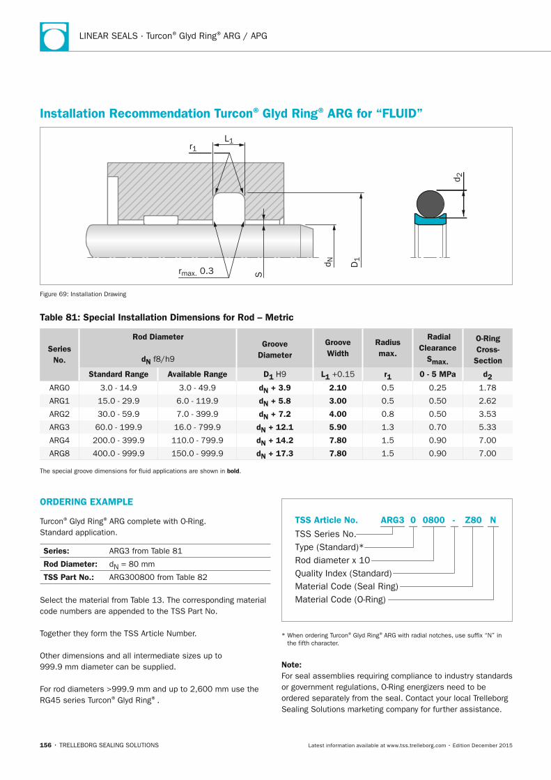
LINEAR SEALS · Turcon® Glyd Ring® ARG / APG
156 • TRELLEBORG SEALING SOLUTIONS Latest information available at www.tss.trelleborg.com • Edition December 2015
Installation Recommendation Turcon® Glyd Ring® ARG for “FLUID”
S
D1
d N
L1r1
rmax. 0.3
d 2
Figure 69: Installation Drawing
Table 81: Special Installation Dimensions for Rod – Metric
Series no.
Rod Diameter
dn f8/h9
Groove Diameter
Groove Width
Radius max.
Radial Clearance
Smax.
O-Ring Cross-
Section
Standard Range Available Range D1 H9 L1 +0.15 r1 0 - 5 MPa d2
ARG0 3.0 - 14.9 3.0 - 49.9 dn + 3.9 2.10 0.5 0.25 1.78
ARG1 15.0 - 29.9 6.0 - 119.9 dn + 5.8 3.00 0.5 0.50 2.62
ARG2 30.0 - 59.9 7.0 - 399.9 dn + 7.2 4.00 0.8 0.50 3.53
ARG3 60.0 - 199.9 16.0 - 799.9 dn + 12.1 5.90 1.3 0.70 5.33
ARG4 200.0 - 399.9 110.0 - 799.9 dn + 14.2 7.80 1.5 0.90 7.00
ARG8 400.0 - 999.9 150.0 - 999.9 dn + 17.3 7.80 1.5 0.90 7.00
The special groove dimensions for fluid applications are shown in bold.
ORDERInG ExAMPLE
Turcon® Glyd Ring® ARG complete with O-Ring. Standard application.
Series: ARG3 from Table 81
Rod Diameter: dN = 80 mm
TSS Part no.: ARG300800 from Table 82
Select the material from Table 13. The corresponding material code numbers are appended to the TSS Part No.
Together they form the TSS Article Number.
Other dimensions and all intermediate sizes up to 999.9 mm diameter can be supplied.
For rod diameters >999.9 mm and up to 2,600 mm use the RG45 series Turcon® Glyd Ring®.
Material Code (Seal Ring)
TSS Series No.
TSS Article No.
Material Code (O-Ring)
Rod diameter x 10Quality Index (Standard)
Type (Standard)*
Z80 NARG3 -0 0800
* When ordering Turcon® Glyd Ring® ARG with radial notches, use suffix “N” in the fifth character.
note: For seal assemblies requiring compliance to industry standards or government regulations, O-Ring energizers need to be ordered separately from the seal. Contact your local Trelleborg Sealing Solutions marketing company for further assistance.
FBP_neues_Layout_2015.indb 156 17.10.2016 13:36:42
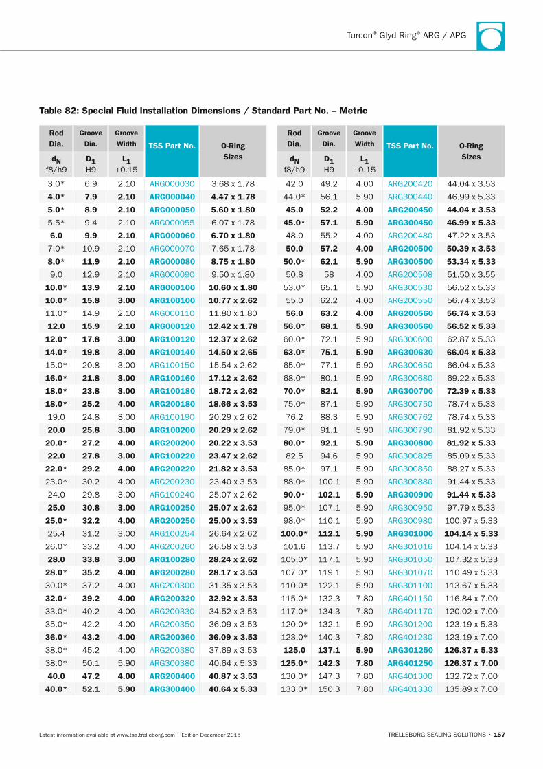
Turcon® Glyd Ring® ARG / APG
TRELLEBORG SEALING SOLUTIONS • 157Latest information available at www.tss.trelleborg.com • Edition December 2015
Rod Dia.
Groove Dia.
Groove Width TSS Part no. O-Ring
Sizesdn f8/h9
D1 H9
L1 +0.15
3.0* 6.9 2.10 ARG000030 3.68 x 1.78
4.0* 7.9 2.10 ARG000040 4.47 x 1.78
5.0* 8.9 2.10 ARG000050 5.60 x 1.80
5.5* 9.4 2.10 ARG000055 6.07 x 1.78
6.0 9.9 2.10 ARG000060 6.70 x 1.80
7.0* 10.9 2.10 ARG000070 7.65 x 1.78
8.0* 11.9 2.10 ARG000080 8.75 x 1.80
9.0 12.9 2.10 ARG000090 9.50 x 1.80
10.0* 13.9 2.10 ARG000100 10.60 x 1.80
10.0* 15.8 3.00 ARG100100 10.77 x 2.62
11.0* 14.9 2.10 ARG000110 11.80 x 1.80
12.0 15.9 2.10 ARG000120 12.42 x 1.78
12.0* 17.8 3.00 ARG100120 12.37 x 2.62
14.0* 19.8 3.00 ARG100140 14.50 x 2.65
15.0* 20.8 3.00 ARG100150 15.54 x 2.62
16.0* 21.8 3.00 ARG100160 17.12 x 2.62
18.0* 23.8 3.00 ARG100180 18.72 x 2.62
18.0* 25.2 4.00 ARG200180 18.66 x 3.53
19.0 24.8 3.00 ARG100190 20.29 x 2.62
20.0 25.8 3.00 ARG100200 20.29 x 2.62
20.0* 27.2 4.00 ARG200200 20.22 x 3.53
22.0 27.8 3.00 ARG100220 23.47 x 2.62
22.0* 29.2 4.00 ARG200220 21.82 x 3.53
23.0* 30.2 4.00 ARG200230 23.40 x 3.53
24.0 29.8 3.00 ARG100240 25.07 x 2.62
25.0 30.8 3.00 ARG100250 25.07 x 2.62
25.0* 32.2 4.00 ARG200250 25.00 x 3.53
25.4 31.2 3.00 ARG100254 26.64 x 2.62
26.0* 33.2 4.00 ARG200260 26.58 x 3.53
28.0 33.8 3.00 ARG100280 28.24 x 2.62
28.0* 35.2 4.00 ARG200280 28.17 x 3.53
30.0* 37.2 4.00 ARG200300 31.35 x 3.53
32.0* 39.2 4.00 ARG200320 32.92 x 3.53
33.0* 40.2 4.00 ARG200330 34.52 x 3.53
35.0* 42.2 4.00 ARG200350 36.09 x 3.53
36.0* 43.2 4.00 ARG200360 36.09 x 3.53
38.0* 45.2 4.00 ARG200380 37.69 x 3.53
38.0* 50.1 5.90 ARG300380 40.64 x 5.33
40.0 47.2 4.00 ARG200400 40.87 x 3.53
40.0* 52.1 5.90 ARG300400 40.64 x 5.33
Rod Dia.
Groove Dia.
Groove Width TSS Part no. O-Ring
Sizesdn f8/h9
D1 H9
L1 +0.15
42.0 49.2 4.00 ARG200420 44.04 x 3.53
44.0* 56.1 5.90 ARG300440 46.99 x 5.33
45.0 52.2 4.00 ARG200450 44.04 x 3.53
45.0* 57.1 5.90 ARG300450 46.99 x 5.33
48.0 55.2 4.00 ARG200480 47.22 x 3.53
50.0 57.2 4.00 ARG200500 50.39 x 3.53
50.0* 62.1 5.90 ARG300500 53.34 x 5.33
50.8 58 4.00 ARG200508 51.50 x 3.55
53.0* 65.1 5.90 ARG300530 56.52 x 5.33
55.0 62.2 4.00 ARG200550 56.74 x 3.53
56.0 63.2 4.00 ARG200560 56.74 x 3.53
56.0* 68.1 5.90 ARG300560 56.52 x 5.33
60.0* 72.1 5.90 ARG300600 62.87 x 5.33
63.0* 75.1 5.90 ARG300630 66.04 x 5.33
65.0* 77.1 5.90 ARG300650 66.04 x 5.33
68.0* 80.1 5.90 ARG300680 69.22 x 5.33
70.0* 82.1 5.90 ARG300700 72.39 x 5.33
75.0* 87.1 5.90 ARG300750 78.74 x 5.33
76.2 88.3 5.90 ARG300762 78.74 x 5.33
79.0* 91.1 5.90 ARG300790 81.92 x 5.33
80.0* 92.1 5.90 ARG300800 81.92 x 5.33
82.5 94.6 5.90 ARG300825 85.09 x 5.33
85.0* 97.1 5.90 ARG300850 88.27 x 5.33
88.0* 100.1 5.90 ARG300880 91.44 x 5.33
90.0* 102.1 5.90 ARG300900 91.44 x 5.33
95.0* 107.1 5.90 ARG300950 97.79 x 5.33
98.0* 110.1 5.90 ARG300980 100.97 x 5.33
100.0* 112.1 5.90 ARG301000 104.14 x 5.33
101.6 113.7 5.90 ARG301016 104.14 x 5.33
105.0* 117.1 5.90 ARG301050 107.32 x 5.33
107.0* 119.1 5.90 ARG301070 110.49 x 5.33
110.0* 122.1 5.90 ARG301100 113.67 x 5.33
115.0* 132.3 7.80 ARG401150 116.84 x 7.00
117.0* 134.3 7.80 ARG401170 120.02 x 7.00
120.0* 132.1 5.90 ARG301200 123.19 x 5.33
123.0* 140.3 7.80 ARG401230 123.19 x 7.00
125.0 137.1 5.90 ARG301250 126.37 x 5.33
125.0* 142.3 7.80 ARG401250 126.37 x 7.00
130.0* 147.3 7.80 ARG401300 132.72 x 7.00
133.0* 150.3 7.80 ARG401330 135.89 x 7.00
Table 82: Special Fluid Installation Dimensions / Standard Part no. – Metric
FBP_neues_Layout_2015.indb 157 17.10.2016 13:36:42
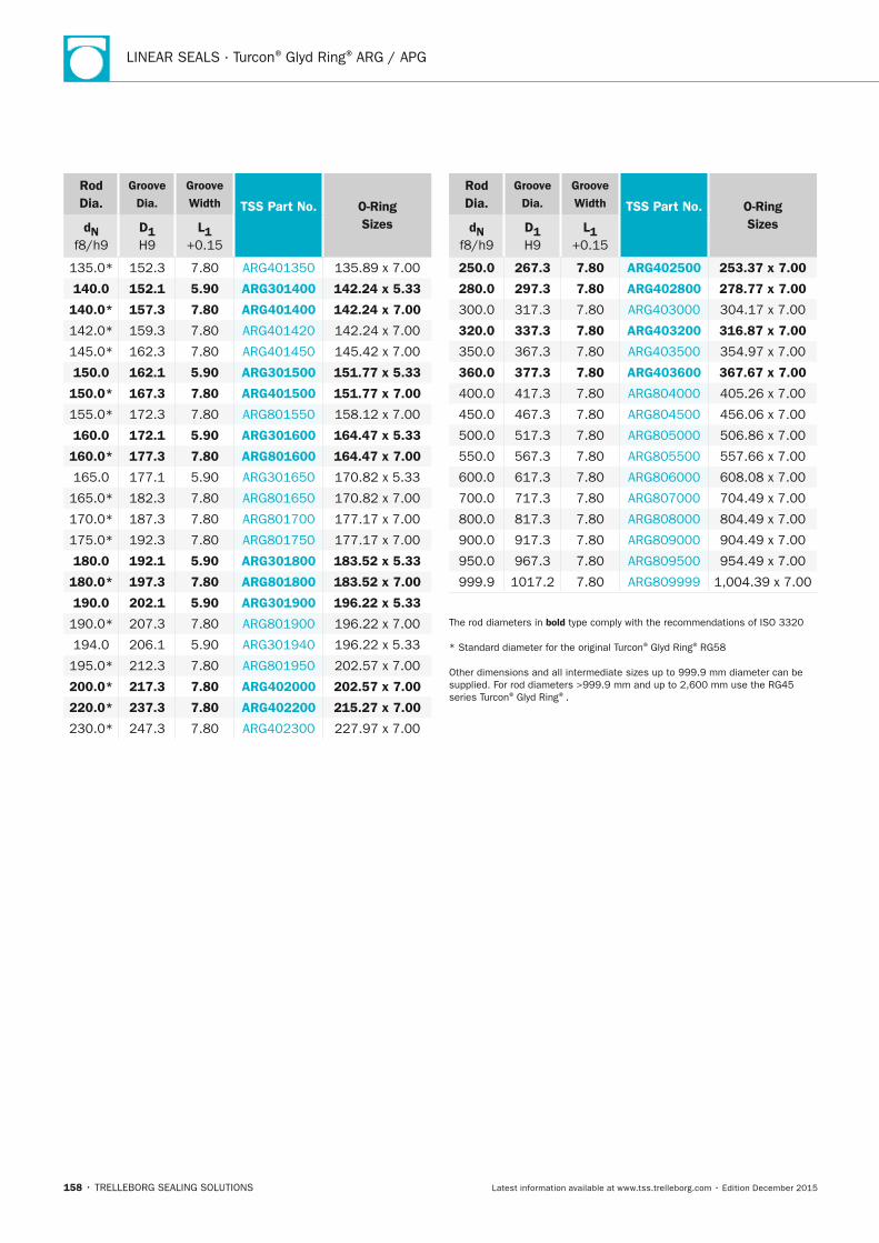
LINEAR SEALS · Turcon® Glyd Ring® ARG / APG
158 • TRELLEBORG SEALING SOLUTIONS Latest information available at www.tss.trelleborg.com • Edition December 2015
Rod Dia.
Groove Dia.
Groove Width TSS Part no. O-Ring
Sizesdn f8/h9
D1 H9
L1 +0.15
135.0* 152.3 7.80 ARG401350 135.89 x 7.00
140.0 152.1 5.90 ARG301400 142.24 x 5.33
140.0* 157.3 7.80 ARG401400 142.24 x 7.00
142.0* 159.3 7.80 ARG401420 142.24 x 7.00
145.0* 162.3 7.80 ARG401450 145.42 x 7.00
150.0 162.1 5.90 ARG301500 151.77 x 5.33
150.0* 167.3 7.80 ARG401500 151.77 x 7.00
155.0* 172.3 7.80 ARG801550 158.12 x 7.00
160.0 172.1 5.90 ARG301600 164.47 x 5.33
160.0* 177.3 7.80 ARG801600 164.47 x 7.00
165.0 177.1 5.90 ARG301650 170.82 x 5.33
165.0* 182.3 7.80 ARG801650 170.82 x 7.00
170.0* 187.3 7.80 ARG801700 177.17 x 7.00
175.0* 192.3 7.80 ARG801750 177.17 x 7.00
180.0 192.1 5.90 ARG301800 183.52 x 5.33
180.0* 197.3 7.80 ARG801800 183.52 x 7.00
190.0 202.1 5.90 ARG301900 196.22 x 5.33
190.0* 207.3 7.80 ARG801900 196.22 x 7.00
194.0 206.1 5.90 ARG301940 196.22 x 5.33
195.0* 212.3 7.80 ARG801950 202.57 x 7.00
200.0* 217.3 7.80 ARG402000 202.57 x 7.00
220.0* 237.3 7.80 ARG402200 215.27 x 7.00
230.0* 247.3 7.80 ARG402300 227.97 x 7.00
Rod Dia.
Groove Dia.
Groove Width TSS Part no. O-Ring
Sizesdn f8/h9
D1 H9
L1 +0.15
250.0 267.3 7.80 ARG402500 253.37 x 7.00
280.0 297.3 7.80 ARG402800 278.77 x 7.00
300.0 317.3 7.80 ARG403000 304.17 x 7.00
320.0 337.3 7.80 ARG403200 316.87 x 7.00
350.0 367.3 7.80 ARG403500 354.97 x 7.00
360.0 377.3 7.80 ARG403600 367.67 x 7.00
400.0 417.3 7.80 ARG804000 405.26 x 7.00
450.0 467.3 7.80 ARG804500 456.06 x 7.00
500.0 517.3 7.80 ARG805000 506.86 x 7.00
550.0 567.3 7.80 ARG805500 557.66 x 7.00
600.0 617.3 7.80 ARG806000 608.08 x 7.00
700.0 717.3 7.80 ARG807000 704.49 x 7.00
800.0 817.3 7.80 ARG808000 804.49 x 7.00
900.0 917.3 7.80 ARG809000 904.49 x 7.00
950.0 967.3 7.80 ARG809500 954.49 x 7.00
999.9 1017.2 7.80 ARG809999 1,004.39 x 7.00
The rod diameters in bold type comply with the recommendations of ISO 3320
* Standard diameter for the original Turcon® Glyd Ring® RG58
Other dimensions and all intermediate sizes up to 999.9 mm diameter can be supplied. For rod diameters >999.9 mm and up to 2,600 mm use the RG45 series Turcon® Glyd Ring®.
FBP_neues_Layout_2015.indb 158 17.10.2016 13:36:43

Turcon® Glyd Ring® ARG / APG
TRELLEBORG SEALING SOLUTIONS • 159Latest information available at www.tss.trelleborg.com • Edition December 2015
FBP_neues_Layout_2015.indb 159 17.10.2016 13:36:43
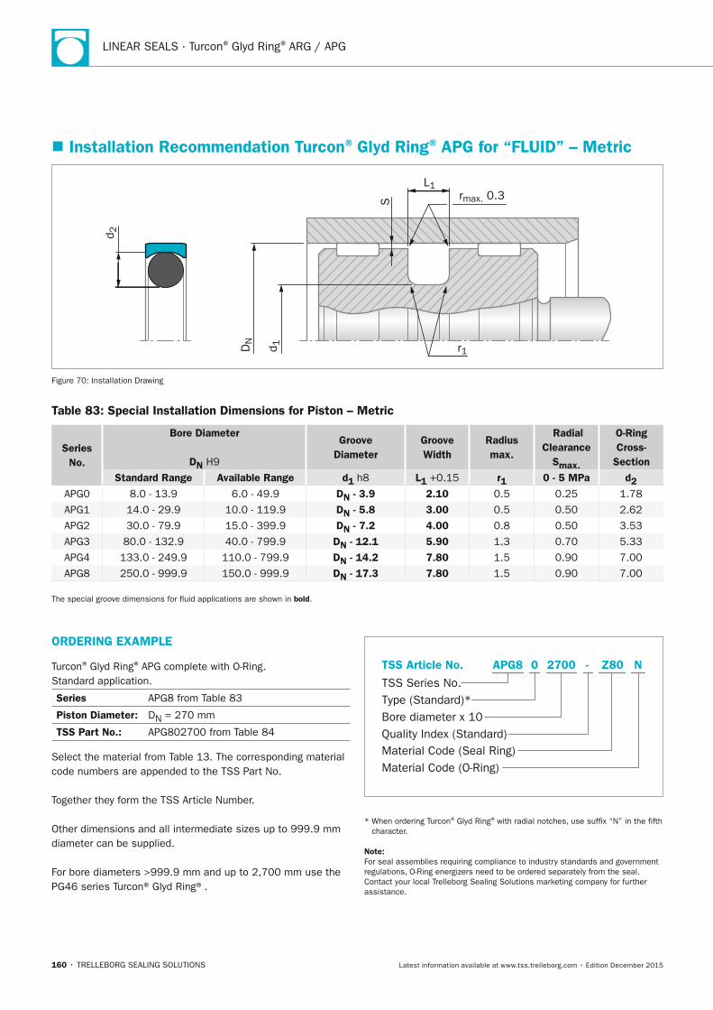
LINEAR SEALS · Turcon® Glyd Ring® ARG / APG
160 • TRELLEBORG SEALING SOLUTIONS Latest information available at www.tss.trelleborg.com • Edition December 2015
� Installation Recommendation Turcon® Glyd Ring® APG for “FLUID” – Metric
rmax. 0.3S
L1
r1
d 2
DN
d 1
Figure 70: Installation Drawing
Table 83: Special Installation Dimensions for Piston – Metric
Series no.
Bore Diameter
Dn H9
Groove Diameter
Groove Width
Radius max.
Radial Clearance
Smax.
O-Ring Cross-
SectionStandard Range Available Range d1 h8 L1 +0.15 r1 0 - 5 MPa d2
APG0 8.0 - 13.9 6.0 - 49.9 Dn - 3.9 2.10 0.5 0.25 1.78
APG1 14.0 - 29.9 10.0 - 119.9 Dn - 5.8 3.00 0.5 0.50 2.62
APG2 30.0 - 79.9 15.0 - 399.9 Dn - 7.2 4.00 0.8 0.50 3.53
APG3 80.0 - 132.9 40.0 - 799.9 Dn - 12.1 5.90 1.3 0.70 5.33
APG4 133.0 - 249.9 110.0 - 799.9 Dn - 14.2 7.80 1.5 0.90 7.00
APG8 250.0 - 999.9 150.0 - 999.9 Dn - 17.3 7.80 1.5 0.90 7.00
The special groove dimensions for fluid applications are shown in bold.
ORDERInG ExAMPLE
Turcon® Glyd Ring® APG complete with O-Ring. Standard application.
Series APG8 from Table 83
Piston Diameter: DN = 270 mm
TSS Part no.: APG802700 from Table 84
Select the material from Table 13. The corresponding material code numbers are appended to the TSS Part No.
Together they form the TSS Article Number.
Other dimensions and all intermediate sizes up to 999.9 mm diameter can be supplied.
For bore diameters >999.9 mm and up to 2,700 mm use the PG46 series Turcon® Glyd Ring®.
Material Code (Seal Ring)
TSS Series No.
TSS Article No.
Material Code (O-Ring)
Bore diameter x 10Quality Index (Standard)
Type (Standard)*
Z80 NAPG8 -0 2700
* When ordering Turcon® Glyd Ring® with radial notches, use suffix “N” in the fifth character.
note: For seal assemblies requiring compliance to industry standards and government regulations, O-Ring energizers need to be ordered separately from the seal. Contact your local Trelleborg Sealing Solutions marketing company for further assistance.
FBP_neues_Layout_2015.indb 160 17.10.2016 13:36:44
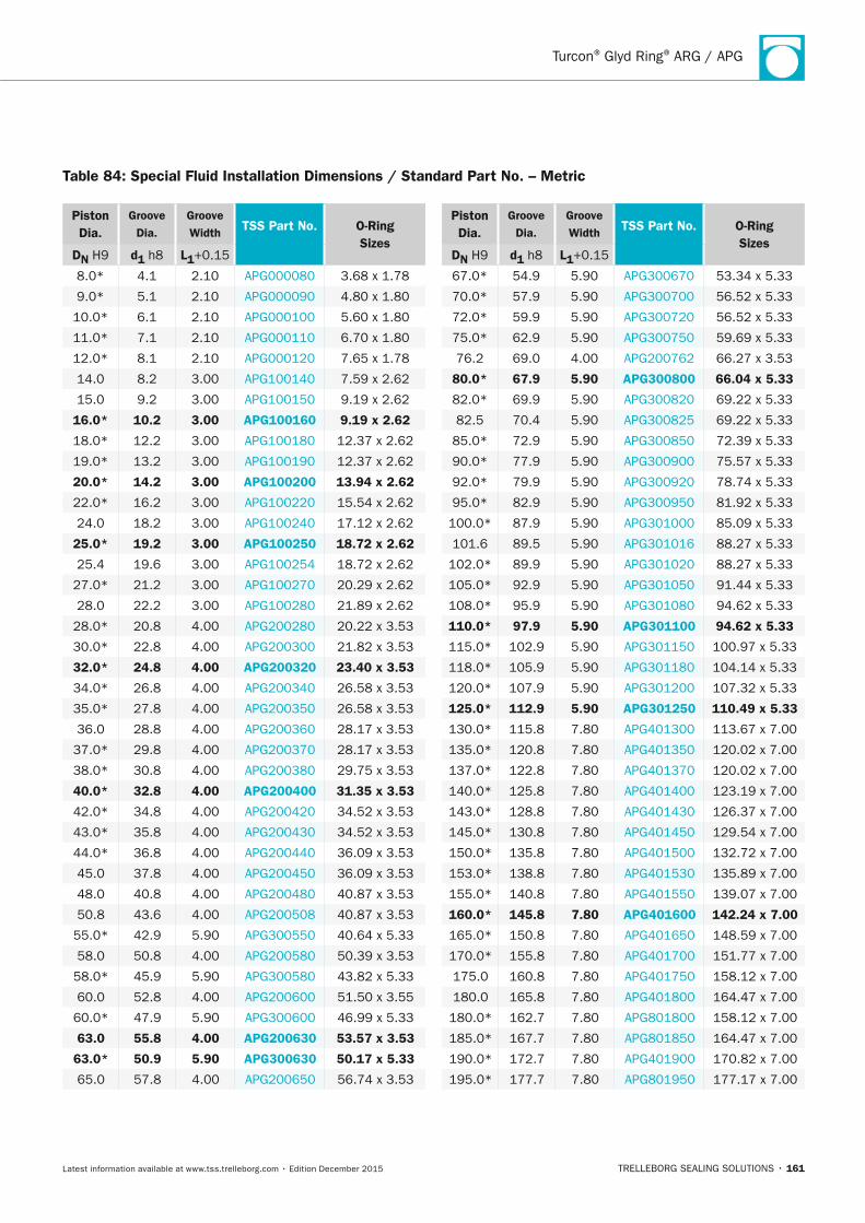
Turcon® Glyd Ring® ARG / APG
TRELLEBORG SEALING SOLUTIONS • 161Latest information available at www.tss.trelleborg.com • Edition December 2015
Piston Dia.
Groove Dia.
Groove Width TSS Part no. O-Ring
SizesDn H9 d1 h8 L1+0.15
8.0* 4.1 2.10 APG000080 3.68 x 1.78
9.0* 5.1 2.10 APG000090 4.80 x 1.80
10.0* 6.1 2.10 APG000100 5.60 x 1.80
11.0* 7.1 2.10 APG000110 6.70 x 1.80
12.0* 8.1 2.10 APG000120 7.65 x 1.78
14.0 8.2 3.00 APG100140 7.59 x 2.62
15.0 9.2 3.00 APG100150 9.19 x 2.62
16.0* 10.2 3.00 APG100160 9.19 x 2.62
18.0* 12.2 3.00 APG100180 12.37 x 2.62
19.0* 13.2 3.00 APG100190 12.37 x 2.62
20.0* 14.2 3.00 APG100200 13.94 x 2.62
22.0* 16.2 3.00 APG100220 15.54 x 2.62
24.0 18.2 3.00 APG100240 17.12 x 2.62
25.0* 19.2 3.00 APG100250 18.72 x 2.62
25.4 19.6 3.00 APG100254 18.72 x 2.62
27.0* 21.2 3.00 APG100270 20.29 x 2.62
28.0 22.2 3.00 APG100280 21.89 x 2.62
28.0* 20.8 4.00 APG200280 20.22 x 3.53
30.0* 22.8 4.00 APG200300 21.82 x 3.53
32.0* 24.8 4.00 APG200320 23.40 x 3.53
34.0* 26.8 4.00 APG200340 26.58 x 3.53
35.0* 27.8 4.00 APG200350 26.58 x 3.53
36.0 28.8 4.00 APG200360 28.17 x 3.53
37.0* 29.8 4.00 APG200370 28.17 x 3.53
38.0* 30.8 4.00 APG200380 29.75 x 3.53
40.0* 32.8 4.00 APG200400 31.35 x 3.53
42.0* 34.8 4.00 APG200420 34.52 x 3.53
43.0* 35.8 4.00 APG200430 34.52 x 3.53
44.0* 36.8 4.00 APG200440 36.09 x 3.53
45.0 37.8 4.00 APG200450 36.09 x 3.53
48.0 40.8 4.00 APG200480 40.87 x 3.53
50.8 43.6 4.00 APG200508 40.87 x 3.53
55.0* 42.9 5.90 APG300550 40.64 x 5.33
58.0 50.8 4.00 APG200580 50.39 x 3.53
58.0* 45.9 5.90 APG300580 43.82 x 5.33
60.0 52.8 4.00 APG200600 51.50 x 3.55
60.0* 47.9 5.90 APG300600 46.99 x 5.33
63.0 55.8 4.00 APG200630 53.57 x 3.53
63.0* 50.9 5.90 APG300630 50.17 x 5.33
65.0 57.8 4.00 APG200650 56.74 x 3.53
Piston Dia.
Groove Dia.
Groove Width TSS Part no. O-Ring
SizesDn H9 d1 h8 L1+0.15
67.0* 54.9 5.90 APG300670 53.34 x 5.33
70.0* 57.9 5.90 APG300700 56.52 x 5.33
72.0* 59.9 5.90 APG300720 56.52 x 5.33
75.0* 62.9 5.90 APG300750 59.69 x 5.33
76.2 69.0 4.00 APG200762 66.27 x 3.53
80.0* 67.9 5.90 APG300800 66.04 x 5.33
82.0* 69.9 5.90 APG300820 69.22 x 5.33
82.5 70.4 5.90 APG300825 69.22 x 5.33
85.0* 72.9 5.90 APG300850 72.39 x 5.33
90.0* 77.9 5.90 APG300900 75.57 x 5.33
92.0* 79.9 5.90 APG300920 78.74 x 5.33
95.0* 82.9 5.90 APG300950 81.92 x 5.33
100.0* 87.9 5.90 APG301000 85.09 x 5.33
101.6 89.5 5.90 APG301016 88.27 x 5.33
102.0* 89.9 5.90 APG301020 88.27 x 5.33
105.0* 92.9 5.90 APG301050 91.44 x 5.33
108.0* 95.9 5.90 APG301080 94.62 x 5.33
110.0* 97.9 5.90 APG301100 94.62 x 5.33
115.0* 102.9 5.90 APG301150 100.97 x 5.33
118.0* 105.9 5.90 APG301180 104.14 x 5.33
120.0* 107.9 5.90 APG301200 107.32 x 5.33
125.0* 112.9 5.90 APG301250 110.49 x 5.33
130.0* 115.8 7.80 APG401300 113.67 x 7.00
135.0* 120.8 7.80 APG401350 120.02 x 7.00
137.0* 122.8 7.80 APG401370 120.02 x 7.00
140.0* 125.8 7.80 APG401400 123.19 x 7.00
143.0* 128.8 7.80 APG401430 126.37 x 7.00
145.0* 130.8 7.80 APG401450 129.54 x 7.00
150.0* 135.8 7.80 APG401500 132.72 x 7.00
153.0* 138.8 7.80 APG401530 135.89 x 7.00
155.0* 140.8 7.80 APG401550 139.07 x 7.00
160.0* 145.8 7.80 APG401600 142.24 x 7.00
165.0* 150.8 7.80 APG401650 148.59 x 7.00
170.0* 155.8 7.80 APG401700 151.77 x 7.00
175.0 160.8 7.80 APG401750 158.12 x 7.00
180.0 165.8 7.80 APG401800 164.47 x 7.00
180.0* 162.7 7.80 APG801800 158.12 x 7.00
185.0* 167.7 7.80 APG801850 164.47 x 7.00
190.0* 172.7 7.80 APG401900 170.82 x 7.00
195.0* 177.7 7.80 APG801950 177.17 x 7.00
Table 84: Special Fluid Installation Dimensions / Standard Part no. – Metric
FBP_neues_Layout_2015.indb 161 17.10.2016 13:36:44
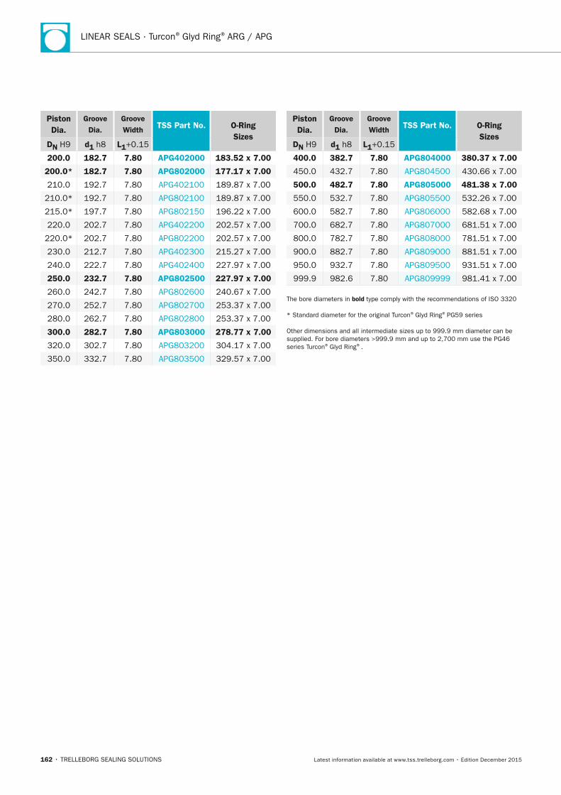
LINEAR SEALS · Turcon® Glyd Ring® ARG / APG
162 • TRELLEBORG SEALING SOLUTIONS Latest information available at www.tss.trelleborg.com • Edition December 2015
Piston Dia.
Groove Dia.
Groove Width TSS Part no. O-Ring
SizesDn H9 d1 h8 L1+0.15
200.0 182.7 7.80 APG402000 183.52 x 7.00
200.0* 182.7 7.80 APG802000 177.17 x 7.00
210.0 192.7 7.80 APG402100 189.87 x 7.00
210.0* 192.7 7.80 APG802100 189.87 x 7.00
215.0* 197.7 7.80 APG802150 196.22 x 7.00
220.0 202.7 7.80 APG402200 202.57 x 7.00
220.0* 202.7 7.80 APG802200 202.57 x 7.00
230.0 212.7 7.80 APG402300 215.27 x 7.00
240.0 222.7 7.80 APG402400 227.97 x 7.00
250.0 232.7 7.80 APG802500 227.97 x 7.00
260.0 242.7 7.80 APG802600 240.67 x 7.00
270.0 252.7 7.80 APG802700 253.37 x 7.00
280.0 262.7 7.80 APG802800 253.37 x 7.00
300.0 282.7 7.80 APG803000 278.77 x 7.00
320.0 302.7 7.80 APG803200 304.17 x 7.00
350.0 332.7 7.80 APG803500 329.57 x 7.00
Piston Dia.
Groove Dia.
Groove Width TSS Part no. O-Ring
SizesDn H9 d1 h8 L1+0.15
400.0 382.7 7.80 APG804000 380.37 x 7.00
450.0 432.7 7.80 APG804500 430.66 x 7.00
500.0 482.7 7.80 APG805000 481.38 x 7.00
550.0 532.7 7.80 APG805500 532.26 x 7.00
600.0 582.7 7.80 APG806000 582.68 x 7.00
700.0 682.7 7.80 APG807000 681.51 x 7.00
800.0 782.7 7.80 APG808000 781.51 x 7.00
900.0 882.7 7.80 APG809000 881.51 x 7.00
950.0 932.7 7.80 APG809500 931.51 x 7.00
999.9 982.6 7.80 APG809999 981.41 x 7.00
The bore diameters in bold type comply with the recommendations of ISO 3320
* Standard diameter for the original Turcon® Glyd Ring® PG59 series
Other dimensions and all intermediate sizes up to 999.9 mm diameter can be supplied. For bore diameters >999.9 mm and up to 2,700 mm use the PG46 series Turcon® Glyd Ring®.
FBP_neues_Layout_2015.indb 162 17.10.2016 13:36:44
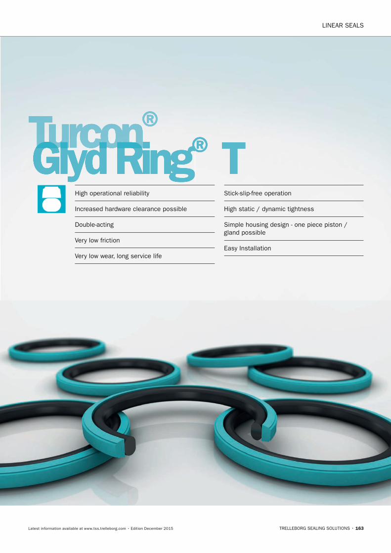
LINEAR SEALS
TRELLEBORG SEALING SOLUTIONS • 163Latest information available at www.tss.trelleborg.com • Edition December 2015
Turcon®Turcon®TurconGlyd RingTurconGlyd RingTurcon ®Glyd Ring®Glyd Ring THigh operational reliability
Increased hardware clearance possible
Double-acting
Very low friction
Very low wear, long service life
Stick-slip-free operation
High static / dynamic tightness
Simple housing design - one piece piston / gland possible
Easy Installation
FBP_neues_Layout_2015.indb 163 17.10.2016 13:36:47

LINEAR SEALS · Turcon® Glyd Ring® T
164 • TRELLEBORG SEALING SOLUTIONS Latest information available at www.tss.trelleborg.com • Edition December 2015
FBP_neues_Layout_2015.indb 164 17.10.2016 13:36:47
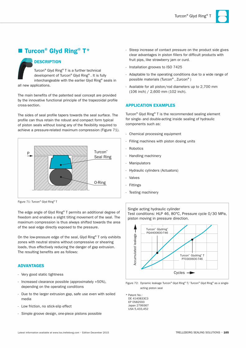
Turcon® Glyd Ring® T
TRELLEBORG SEALING SOLUTIONS • 165Latest information available at www.tss.trelleborg.com • Edition December 2015
� Turcon® Glyd Ring® T*
DESCRIPTIOn
Turcon® Glyd Ring® T is a further technical development of Turcon® Glyd Ring®. It is fully interchangeable with the earlier Glyd Ring® seals in
all new applications.
The main benefits of the patented seal concept are provided by the innovative functional principle of the trapezoidal profile cross-section.
The sides of seal profile tapers towards the seal surface. The profile can thus retain the robust and compact form typical of piston seals without losing any of the flexibility required to achieve a pressure-related maximum compression (Figure 71).
P Turcon® Seal Ring
O-Ring
Figure 71: Turcon® Glyd Ring® T
The edge angle of Glyd Ring® T permits an additional degree of freedom and enables a slight tilting movement of the seal. The maximum compression is thus always shifted towards the area of the seal edge directly exposed to the pressure.
On the low-pressure edge of the seal, Glyd Ring® T only exhibits zones with neutral strains without compressive or shearing loads, thus effectively reducing the danger of gap extrusion. The resulting benefits are as follows:
ADVAnTAGES
- Very good static tightness
- Increased clearance possible (approximately +50%), depending on the operating conditions
- Due to the larger extrusion gap, safe use even with soiled media
- Low friction, no stick-slip effect
- Simple groove design, one-piece pistons possible
- Steep increase of contact pressure on the product side gives clear advantages in piston fillers for difficult products with fruit pips, like strawberry jam or curd.
- Installation grooves to ISO 7425
- Adaptable to the operating conditions due to a wide range of possible materials (Turcon®, Zurcon®)
- Available for all piston/rod diameters up to 2,700 mm (106 inch) / 2,600 mm (102 inch).
APPLICATIOn ExAMPLES
Turcon® Glyd Ring® T is the recommended sealing element for single- and double-acting inside sealing of hydraulic components such as:
- Chemical processing equipment
- Filling machines with piston dosing units
- Robotics
- Handling machinery
- Manipulators
- Hydraulic cylinders (Actuators)
- Valves
- Fittings
- Testing machinery
Single acting hydraulic cylinderTest conditions: HLP 46, 80°C, Pressure cycle 0/30 MPa,piston moving in pressure direction.
Cycles
Accu
mul
ated
leak
age
Turcon® Glydring®
PG4400600-T46
Turcon® Glydring® TPT0300600-T46
Figure 72: Dynamic leakage Turcon® Glyd Ring® T/ Turcon® Glyd Ring® as a single-
acting piston seal
* Patent No.: DE 4140833C3 EP 0582593 Japan 2799367 USA 5,433,452
FBP_neues_Layout_2015.indb 165 17.10.2016 13:36:49
LINEAR SEALS · Turcon® Glyd Ring® T
166 • TRELLEBORG SEALING SOLUTIONS Latest information available at www.tss.trelleborg.com • Edition December 2015
TECHnICAL DATA
Operating conditions
Pressure: Up to 60 MPa / 8,700 psi
Speed: Up to 15 m/s / 2,952 fpm
Temperature: -45 °C to +150 °C*) / -45 °F to +32 °F*) (depending on O-Ring material)
Media: Food products like jam or curd, highly-viscous products like honey, fluids (bio-oils), phosphate ester, water, air and others, depending on the seal and O-Ring material compatibility
Clearance: The maximum permissible radial clearance Smax is shown in Table 87, as a function of the operating pressure and functional diameter.
IMPORTAnT nOTE
The above data are maximum values and cannot be used at the same time, e.g. the maximum operating speed depends on material type, pressure, temperature and gap value. Temperature range also depends on the media.
*) IMPORTAnT nOTE FOR THE PISTOn VERSIOn:
In case of unpressurized applications in temperatures below 0 °C / +32 °F contact your local Trellleborg Sealing Solutions marketing company for more information!
SURFACE FInISH RECOMMEnDATIOn
Recommended surface of Piston / Rod is described in the Hardware & Design Expertise chapter from page 13 to 16.
SERIES
Different cross-section sizes are recommended as a function of the seal diameters.
Table 87 and Table 88 show the relationship between the series number according to the seal diameter range and the different application class sizes. These application classes are:
Standard application: General applications with no exceptional operating conditions.
Light application: Applications with demands for reduced friction or for smaller grooves.
Heavy-duty application: For exceptional operating loads such as high pressures, pressure peaks, etc.
RECOMMEnDED MATERIALS
Standard ApplicationsThe following material combinations have proven effective for food, beverage and pharmaceutical fluid applications:
Glyd Ring® T in Turcon® MF6:All round material with high sealing effect for light to medium applications in fluids and gases with requirements for compliance to various regulations. MF6 is the Turcon® material in compliance with most food, beverage and pharmaceutical regulations (see Table 13 on page 33).
O-Ring: EPDM 70 Shore A E (according to temperature, required approvals and availability)
Set Code: MF6E
AlternativeGlyd Ring® T in Turcon® MF4:All-round material for use with lubricating fluids and fluids with limited lubrication (e.g. water). Surface texture is not suitable for gas sealing.
O-Ring: NBR 70 Shore A N FKM 70 Shore A V (according to temperature, required approvals and availability)
Other seal ring materials and elastomers are available on request. Contact your local Trelleborg Sealing Solutions marketing company for more information.
Standard Hydraulic ApplicationsThe following material combination has proven effective for light to heavy duty hydraulic applications:
Glyd Ring® T in Turcon® M12:All round material for applications with linear or helical movements in mineral oils, flame retardant hydraulic fluids, phosphate ester, bio-oils or fluids with low lubricating properties.
O-Ring: NBR 70 Shore A N FKM 70 Shore A V (depending on the temperature)
Set code: M12N or M12V
Specialized Turcon® materials are available for all applications.
FBP_neues_Layout_2015.indb 166 17.10.2016 13:36:49
Turcon® Glyd Ring® T
TRELLEBORG SEALING SOLUTIONS • 167Latest information available at www.tss.trelleborg.com • Edition December 2015
Table 85: Available Range for Piston Seals – Metric
Series no. Piston Diameter dn f8/h9
RT00 2.0 - 130.0
RT01 4.0 - 240.0
RT02 6.0 - 450.0
RT03 12.0 - 650.0
RT04 38.0 - 650.0
RT08 200.0 - 999.9
RT05 256.0 - 999.9
RT05X 1,000.0 - 1,200.0
RT06 650.0 - 999.9
RT06X 1,000.0 - 2,600.0
For the recommended range see Table 87.
Table 86: Available Range for Rod Seals – Metric
Series no. Rod Diameter Dn H9
PT00 8.0 - 140.0
PT01 8.0 - 200.0
PT02 16.0 - 380.0
PT03 40.0 - 480.0
PT04 80.0 - 700.0
PT08 133.0 - 999.9
PT05 310.0 - 999.9
PT05X 1,000.0 - 1,200.0
PT06 750.0 - 999.9
PT06X 1,000.0 - 2,700.0
For the recommended range see Table 87.
Installation of Turcon® Glyd Ring® TThe seal is preferably installed in a closed groove. Glyd Ring®
T for piston and rod is installed according to information on pages 20 to 23.
FBP_neues_Layout_2015.indb 167 17.10.2016 13:36:49
LINEAR SEALS · Turcon® Glyd Ring® T
168 • TRELLEBORG SEALING SOLUTIONS Latest information available at www.tss.trelleborg.com • Edition December 2015
� Installation Recommendation Rod – Metric
D1
r1L1
rmax. 0.3 d NSP P
d 2
Figure 73: Installation Drawing
Table 87: Installation Dimensions – Standard Recommendations – Metric
Series no. Rod Diameter dn f8/h9
Groove Diameter*
Groove Width
Radius Radial Clearance Smax**
O-Ring Size
Standard Application
Light Application
Heavy Duty Application
D1 H9 L1 +0.2 r1 10 MPa 20 MPa 40 MPa d2
RT00 3 - 7.9 8 - 18.9 - dN + 4.9 2.2 0.4 0.30 0.20 0.15 1.78
RT01 8 - 18.9 19 - 37.9 - dN + 7.3 3.2 0.6 0.40 0.25 0.15 2.62
RT02 19 - 37.9 38 - 199.9 8 - 18.9 dN + 10.7 4.2 1.0 0.50 0.30 0.20 3.53
RT03 38 - 199.9 200 - 255.9 19 - 37.9 dN + 15.1 6.3 1.3 0.70 0.40 0.25 5.33
RT04 200 - 255.9 256 - 649.9 38 - 199.9 dN + 20.5 8.1 1.8 0.80 0.60 0.35 7.00
RT08 256 - 649.9 650 - 999.9 200 - 255.9 dN + 24.0 8.1 1.8 0.90 0.70 0.40 7.00
RT05 650 - 999.9 - 256 - 649.9 dN + 27.3 9.5 2.5 1.00 0.80 0.50 8.40
RT05X - 1,000 - 1,2000 - dN + 27.3 9.5 2.5 1.00 0.80 0.50 8.40
RT06*** - - 650 - 999.9 dN + 38.0 13.8 3.0 1.20 0.90 0.60 12.00
RT06X*** 1,000 - 2,6000 - - dN + 38.0 13.8 3.0 1.20 0.90 0.60 12.00
* Installation with groove dimensions to ISO 7425-2 is also recommendable. ** At pressures > 40 MPa use diameter tolerance H8/f8 (bore/rod) in area of the seal or consult your local Trelleborg Sealing Solutions marketing company for
alternative material or profiles. Slydring®/Wear Rings are not applicable at very small radial clearances; consult the Hydraulic Seals - Linear catalog.
*** O-Rings with 12 mm cross section are delivered as a special profile ring.
FBP_neues_Layout_2015.indb 168 17.10.2016 13:36:50
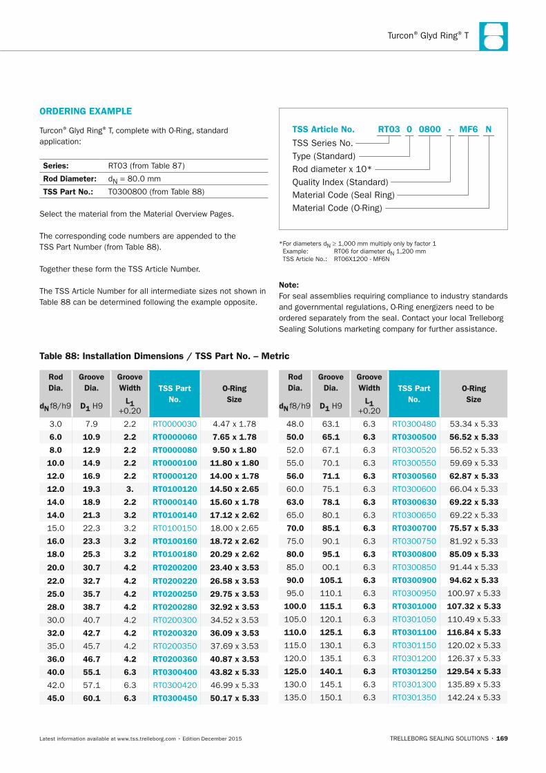
Turcon® Glyd Ring® T
TRELLEBORG SEALING SOLUTIONS • 169Latest information available at www.tss.trelleborg.com • Edition December 2015
ORDERInG ExAMPLE
Turcon® Glyd Ring® T, complete with O-Ring, standard application:
Series: RT03 (from Table 87)
Rod Diameter: dN = 80.0 mm
TSS Part no.: T0300800 (from Table 88)
Select the material from the Material Overview Pages.
The corresponding code numbers are appended to the TSS Part Number (from Table 88).
Together these form the TSS Article Number.
The TSS Article Number for all intermediate sizes not shown in Table 88 can be determined following the example opposite.
Material Code (Seal Ring)
TSS Series No.
TSS Article No.
Material Code (O-Ring)
Rod diameter x 10*Quality Index (Standard)
Type (Standard)
MF6 NRT03 -0 0800
* For diameters dN ≥ 1,000 mm multiply only by factor 1 Example: RT06 for diameter dN 1,200 mm TSS Article No.: RT06X1200 - MF6N
note:For seal assemblies requiring compliance to industry standards and governmental regulations, O-Ring energizers need to be ordered separately from the seal. Contact your local Trelleborg Sealing Solutions marketing company for further assistance.
Rod Dia.
Groove Dia.
Groove Width TSS Part
no.O-Ring Size
dn f8/h9 D1 H9 L1
+0.20
3.0 7.9 2.2 RT0000030 4.47 x 1.78
6.0 10.9 2.2 RT0000060 7.65 x 1.78
8.0 12.9 2.2 RT0000080 9.50 x 1.80
10.0 14.9 2.2 RT0000100 11.80 x 1.80
12.0 16.9 2.2 RT0000120 14.00 x 1.78
12.0 19.3 3. RT0100120 14.50 x 2.65
14.0 18.9 2.2 RT0000140 15.60 x 1.78
14.0 21.3 3.2 RT0100140 17.12 x 2.62
15.0 22.3 3.2 RT0100150 18.00 x 2.65
16.0 23.3 3.2 RT0100160 18.72 x 2.62
18.0 25.3 3.2 RT0100180 20.29 x 2.62
20.0 30.7 4.2 RT0200200 23.40 x 3.53
22.0 32.7 4.2 RT0200220 26.58 x 3.53
25.0 35.7 4.2 RT0200250 29.75 x 3.53
28.0 38.7 4.2 RT0200280 32.92 x 3.53
30.0 40.7 4.2 RT0200300 34.52 x 3.53
32.0 42.7 4.2 RT0200320 36.09 x 3.53
35.0 45.7 4.2 RT0200350 37.69 x 3.53
36.0 46.7 4.2 RT0200360 40.87 x 3.53
40.0 55.1 6.3 RT0300400 43.82 x 5.33
42.0 57.1 6.3 RT0300420 46.99 x 5.33
45.0 60.1 6.3 RT0300450 50.17 x 5.33
Rod Dia.
Groove Dia.
Groove Width TSS Part
no.O-Ring Size
dn f8/h9 D1 H9 L1
+0.20
48.0 63.1 6.3 RT0300480 53.34 x 5.33
50.0 65.1 6.3 RT0300500 56.52 x 5.33
52.0 67.1 6.3 RT0300520 56.52 x 5.33
55.0 70.1 6.3 RT0300550 59.69 x 5.33
56.0 71.1 6.3 RT0300560 62.87 x 5.33
60.0 75.1 6.3 RT0300600 66.04 x 5.33
63.0 78.1 6.3 RT0300630 69.22 x 5.33
65.0 80.1 6.3 RT0300650 69.22 x 5.33
70.0 85.1 6.3 RT0300700 75.57 x 5.33
75.0 90.1 6.3 RT0300750 81.92 x 5.33
80.0 95.1 6.3 RT0300800 85.09 x 5.33
85.0 00.1 6.3 RT0300850 91.44 x 5.33
90.0 105.1 6.3 RT0300900 94.62 x 5.33
95.0 110.1 6.3 RT0300950 100.97 x 5.33
100.0 115.1 6.3 RT0301000 107.32 x 5.33
105.0 120.1 6.3 RT0301050 110.49 x 5.33
110.0 125.1 6.3 RT0301100 116.84 x 5.33
115.0 130.1 6.3 RT0301150 120.02 x 5.33
120.0 135.1 6.3 RT0301200 126.37 x 5.33
125.0 140.1 6.3 RT0301250 129.54 x 5.33
130.0 145.1 6.3 RT0301300 135.89 x 5.33
135.0 150.1 6.3 RT0301350 142.24 x 5.33
Table 88: Installation Dimensions / TSS Part no. – Metric
FBP_neues_Layout_2015.indb 169 17.10.2016 13:36:50
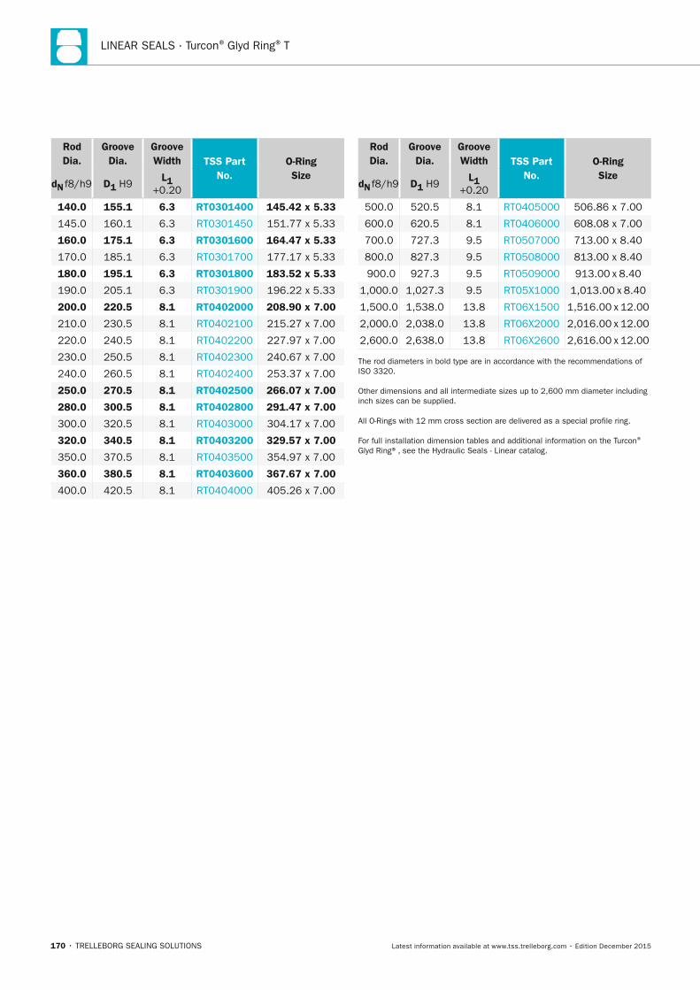
LINEAR SEALS · Turcon® Glyd Ring® T
170 • TRELLEBORG SEALING SOLUTIONS Latest information available at www.tss.trelleborg.com • Edition December 2015
Rod Dia.
Groove Dia.
Groove Width TSS Part
no.O-Ring Size
dn f8/h9 D1 H9 L1
+0.20
140.0 155.1 6.3 RT0301400 145.42 x 5.33
145.0 160.1 6.3 RT0301450 151.77 x 5.33
160.0 175.1 6.3 RT0301600 164.47 x 5.33
170.0 185.1 6.3 RT0301700 177.17 x 5.33
180.0 195.1 6.3 RT0301800 183.52 x 5.33
190.0 205.1 6.3 RT0301900 196.22 x 5.33
200.0 220.5 8.1 RT0402000 208.90 x 7.00
210.0 230.5 8.1 RT0402100 215.27 x 7.00
220.0 240.5 8.1 RT0402200 227.97 x 7.00
230.0 250.5 8.1 RT0402300 240.67 x 7.00
240.0 260.5 8.1 RT0402400 253.37 x 7.00
250.0 270.5 8.1 RT0402500 266.07 x 7.00
280.0 300.5 8.1 RT0402800 291.47 x 7.00
300.0 320.5 8.1 RT0403000 304.17 x 7.00
320.0 340.5 8.1 RT0403200 329.57 x 7.00
350.0 370.5 8.1 RT0403500 354.97 x 7.00
360.0 380.5 8.1 RT0403600 367.67 x 7.00
400.0 420.5 8.1 RT0404000 405.26 x 7.00
Rod Dia.
Groove Dia.
Groove Width TSS Part
no.O-Ring Size
dn f8/h9 D1 H9 L1
+0.20
500.0 520.5 8.1 RT0405000 506.86 x 7.00
600.0 620.5 8.1 RT0406000 608.08 x 7.00
700.0 727.3 9.5 RT0507000 713.00 x 8.40
800.0 827.3 9.5 RT0508000 813.00 x 8.40
900.0 927.3 9.5 RT0509000 913.00 x 8.40
1,000.0 1,027.3 9.5 RT05X1000 1,013.00 x 8.40
1,500.0 1,538.0 13.8 RT06X1500 1,516.00 x 12.00
2,000.0 2,038.0 13.8 RT06X2000 2,016.00 x 12.00
2,600.0 2,638.0 13.8 RT06X2600 2,616.00 x 12.00
The rod diameters in bold type are in accordance with the recommendations of ISO 3320.
Other dimensions and all intermediate sizes up to 2,600 mm diameter including inch sizes can be supplied.
All O-Rings with 12 mm cross section are delivered as a special profile ring.
For full installation dimension tables and additional information on the Turcon®
Glyd Ring®, see the Hydraulic Seals - Linear catalog.
FBP_neues_Layout_2015.indb 170 17.10.2016 13:36:51

Turcon® Glyd Ring® T
TRELLEBORG SEALING SOLUTIONS • 171Latest information available at www.tss.trelleborg.com • Edition December 2015
FBP_neues_Layout_2015.indb 171 17.10.2016 13:36:51
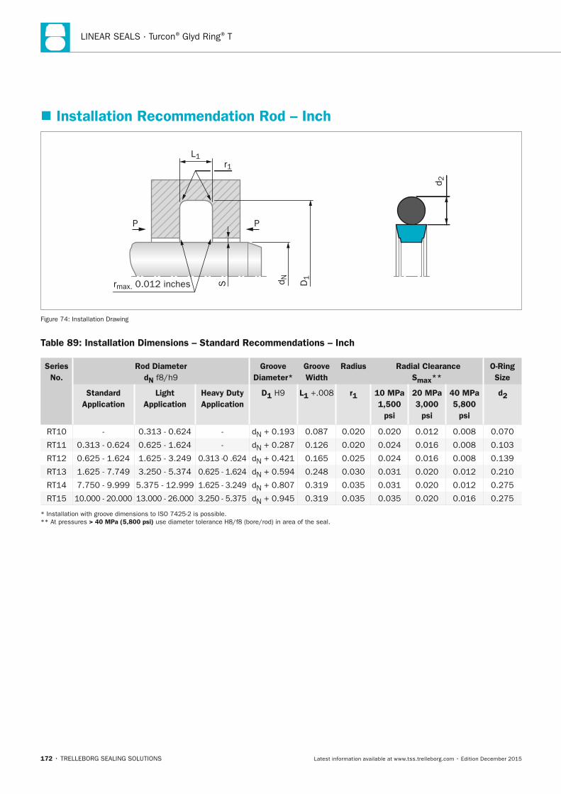
LINEAR SEALS · Turcon® Glyd Ring® T
172 • TRELLEBORG SEALING SOLUTIONS Latest information available at www.tss.trelleborg.com • Edition December 2015
� Installation Recommendation Rod – Inch
rmax. 0.012 inches D1
r1L1
d NSP P
d 2
Figure 74: Installation Drawing
Table 89: Installation Dimensions – Standard Recommendations – Inch
Series no.
Rod Diameter dn f8/h9
Groove Diameter*
Groove Width
Radius Radial Clearance Smax**
O-Ring Size
Standard Application
Light Application
Heavy Duty Application
D1 H9 L1 +.008 r1 10 MPa 1,500
psi
20 MPa 3,000
psi
40 MPa 5,800
psi
d2
RT10 - 0.313 - 0.624 - dN + 0.193 0.087 0.020 0.020 0.012 0.008 0.070
RT11 0.313 - 0.624 0.625 - 1.624 - dN + 0.287 0.126 0.020 0.024 0.016 0.008 0.103
RT12 0.625 - 1.624 1.625 - 3.249 0.313 -0 .624 dN + 0.421 0.165 0.025 0.024 0.016 0.008 0.139
RT13 1.625 - 7.749 3.250 - 5.374 0.625 - 1.624 dN + 0.594 0.248 0.030 0.031 0.020 0.012 0.210
RT14 7.750 - 9.999 5.375 - 12.999 1.625 - 3.249 dN + 0.807 0.319 0.035 0.031 0.020 0.012 0.275
RT15 10.000 - 20.000 13.000 - 26.000 3.250 - 5.375 dN + 0.945 0.319 0.035 0.035 0.020 0.016 0.275
* Installation with groove dimensions to ISO 7425-2 is possible. ** At pressures > 40 MPa (5,800 psi) use diameter tolerance H8/f8 (bore/rod) in area of the seal.
FBP_neues_Layout_2015.indb 172 17.10.2016 13:36:51
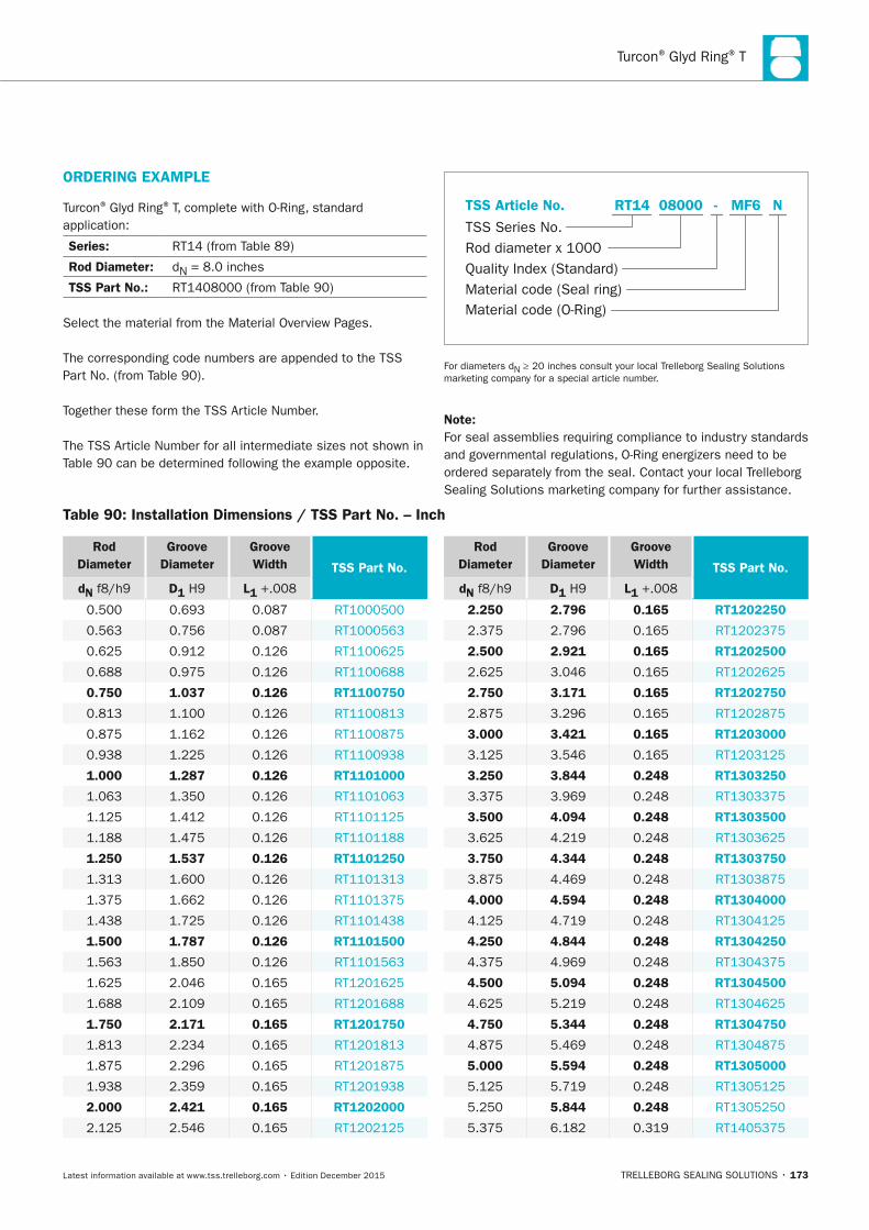
Turcon® Glyd Ring® T
TRELLEBORG SEALING SOLUTIONS • 173Latest information available at www.tss.trelleborg.com • Edition December 2015
Table 90: Installation Dimensions / TSS Part no. – Inch
Rod Diameter
Groove Diameter
Groove Width TSS Part no.
dn f8/h9 D1 H9 L1 +.008
0.500 0.693 0.087 RT1000500
0.563 0.756 0.087 RT1000563
0.625 0.912 0.126 RT1100625
0.688 0.975 0.126 RT1100688
0.750 1.037 0.126 RT1100750
0.813 1.100 0.126 RT1100813
0.875 1.162 0.126 RT1100875
0.938 1.225 0.126 RT1100938
1.000 1.287 0.126 RT1101000
1.063 1.350 0.126 RT1101063
1.125 1.412 0.126 RT1101125
1.188 1.475 0.126 RT1101188
1.250 1.537 0.126 RT1101250
1.313 1.600 0.126 RT1101313
1.375 1.662 0.126 RT1101375
1.438 1.725 0.126 RT1101438
1.500 1.787 0.126 RT1101500
1.563 1.850 0.126 RT1101563
1.625 2.046 0.165 RT1201625
1.688 2.109 0.165 RT1201688
1.750 2.171 0.165 RT1201750
1.813 2.234 0.165 RT1201813
1.875 2.296 0.165 RT1201875
1.938 2.359 0.165 RT1201938
2.000 2.421 0.165 RT1202000
2.125 2.546 0.165 RT1202125
Rod Diameter
Groove Diameter
Groove Width TSS Part no.
dn f8/h9 D1 H9 L1 +.008
2.250 2.796 0.165 RT1202250
2.375 2.796 0.165 RT1202375
2.500 2.921 0.165 RT1202500
2.625 3.046 0.165 RT1202625
2.750 3.171 0.165 RT1202750
2.875 3.296 0.165 RT1202875
3.000 3.421 0.165 RT1203000
3.125 3.546 0.165 RT1203125
3.250 3.844 0.248 RT1303250
3.375 3.969 0.248 RT1303375
3.500 4.094 0.248 RT1303500
3.625 4.219 0.248 RT1303625
3.750 4.344 0.248 RT1303750
3.875 4.469 0.248 RT1303875
4.000 4.594 0.248 RT1304000
4.125 4.719 0.248 RT1304125
4.250 4.844 0.248 RT1304250
4.375 4.969 0.248 RT1304375
4.500 5.094 0.248 RT1304500
4.625 5.219 0.248 RT1304625
4.750 5.344 0.248 RT1304750
4.875 5.469 0.248 RT1304875
5.000 5.594 0.248 RT1305000
5.125 5.719 0.248 RT1305125
5.250 5.844 0.248 RT1305250
5.375 6.182 0.319 RT1405375
ORDERInG ExAMPLE
Turcon® Glyd Ring® T, complete with O-Ring, standard application:
Series: RT14 (from Table 89)
Rod Diameter: dN = 8.0 inches
TSS Part no.: RT1408000 (from Table 90)
Select the material from the Material Overview Pages.
The corresponding code numbers are appended to the TSS Part No. (from Table 90).
Together these form the TSS Article Number.
The TSS Article Number for all intermediate sizes not shown in Table 90 can be determined following the example opposite.
Material code (O-Ring)
TSS Series No.
TSS Article No.
Quality Index (Standard)Material code (Seal ring)
Rod diameter x 1000
MF6 NRT14 -08000
For diameters dN ≥ 20 inches consult your local Trelleborg Sealing Solutions marketing company for a special article number.
note:For seal assemblies requiring compliance to industry standards and governmental regulations, O-Ring energizers need to be ordered separately from the seal. Contact your local Trelleborg Sealing Solutions marketing company for further assistance.
FBP_neues_Layout_2015.indb 173 17.10.2016 13:36:52
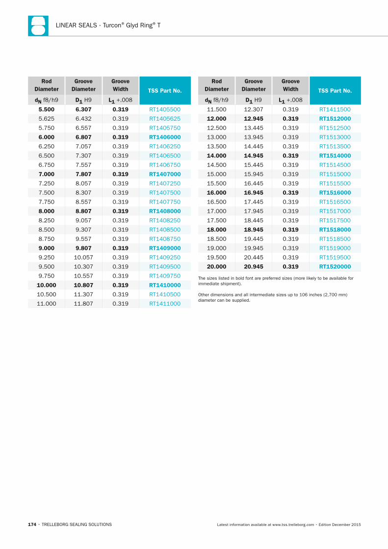
LINEAR SEALS · Turcon® Glyd Ring® T
174 • TRELLEBORG SEALING SOLUTIONS Latest information available at www.tss.trelleborg.com • Edition December 2015
Rod Diameter
Groove Diameter
Groove Width TSS Part no.
dn f8/h9 D1 H9 L1 +.008
5.500 6.307 0.319 RT1405500
5.625 6.432 0.319 RT1405625
5.750 6.557 0.319 RT1405750
6.000 6.807 0.319 RT1406000
6.250 7.057 0.319 RT1406250
6.500 7.307 0.319 RT1406500
6.750 7.557 0.319 RT1406750
7.000 7.807 0.319 RT1407000
7.250 8.057 0.319 RT1407250
7.500 8.307 0.319 RT1407500
7.750 8.557 0.319 RT1407750
8.000 8.807 0.319 RT1408000
8.250 9.057 0.319 RT1408250
8.500 9.307 0.319 RT1408500
8.750 9.557 0.319 RT1408750
9.000 9.807 0.319 RT1409000
9.250 10.057 0.319 RT1409250
9.500 10.307 0.319 RT1409500
9.750 10.557 0.319 RT1409750
10.000 10.807 0.319 RT1410000
10.500 11.307 0.319 RT1410500
11.000 11.807 0.319 RT1411000
Rod Diameter
Groove Diameter
Groove Width TSS Part no.
dn f8/h9 D1 H9 L1 +.008
11.500 12.307 0.319 RT1411500
12.000 12.945 0.319 RT1512000
12.500 13.445 0.319 RT1512500
13.000 13.945 0.319 RT1513000
13.500 14.445 0.319 RT1513500
14.000 14.945 0.319 RT1514000
14.500 15.445 0.319 RT1514500
15.000 15.945 0.319 RT1515000
15.500 16.445 0.319 RT1515500
16.000 16.945 0.319 RT1516000
16.500 17.445 0.319 RT1516500
17.000 17.945 0.319 RT1517000
17.500 18.445 0.319 RT1517500
18.000 18.945 0.319 RT1518000
18.500 19.445 0.319 RT1518500
19.000 19.945 0.319 RT1519000
19.500 20.445 0.319 RT1519500
20.000 20.945 0.319 RT1520000
The sizes listed in bold font are preferred sizes (more likely to be available for immediate shipment).
Other dimensions and all intermediate sizes up to 106 inches (2,700 mm) diameter can be supplied.
FBP_neues_Layout_2015.indb 174 17.10.2016 13:36:52

Turcon® Glyd Ring® T
TRELLEBORG SEALING SOLUTIONS • 175Latest information available at www.tss.trelleborg.com • Edition December 2015
FBP_neues_Layout_2015.indb 175 17.10.2016 13:36:52
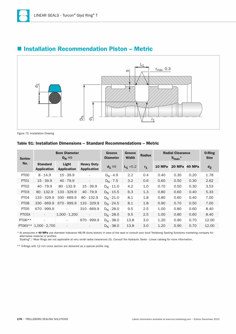
LINEAR SEALS · Turcon® Glyd Ring® T
176 • TRELLEBORG SEALING SOLUTIONS Latest information available at www.tss.trelleborg.com • Edition December 2015
� Installation Recommendation Piston – Metric
S
L1rmax. 0.3
r1
d 2
DN
d 1
Figure 75: Installation Drawing
Table 91: Installation Dimensions – Standard Recommendations – Metric
Series-no.
Bore Diameter Dn H9
Groove Diameter
Groove Width
Radius Radial Clearance
Smax* O-Ring Size
Standard Application
Light Application
Heavy Duty Application
d1 h9 L1 +0.2 r1 10 MPa 20 MPa 40 MPa d2
PT00 8 - 14.9 15 - 39.9 - DN - 4.9 2.2 0.4 0.40 0.30 0.20 1.78
PT01 15 - 39.9 40 - 79.9 - DN - 7.5 3.2 0.6 0.60 0.50 0.30 2.62
PT02 40 - 79.9 80 - 132.9 15 - 39.9 DN - 11.0 4.2 1.0 0.70 0.50 0.30 3.53
PT03 80 - 132.9 133 - 329.9 40 - 79.9 DN - 15.5 6.3 1.3 0.80 0.60 0.40 5.33
PT04 133 - 329.9 330 - 669.9 80 - 132.9 DN - 21.0 8.1 1.8 0.80 0.60 0.40 7.00
PT08 330 - 669.9 670 - 999.9 133 - 329.9 DN - 24.5 8.1 1.8 0.90 0.70 0.50 7.00
PT05 670 - 999.9 - 310 - 669.9 DN - 28.0 9.5 2.5 1.00 0.80 0.60 8.40
PT05X - 1,000 - 1,200 - DN - 28.0 9.5 2.5 1.00 0.80 0.60 8.40
PT06** - - 670 - 999.9 DN - 38.0 13.8 3.0 1.20 0.90 0.70 12.00
PT06X** 1,000 - 2,700 - - DN - 38.0 13.8 3.0 1.20 0.90 0.70 12.00
* At pressures > 40 MPa use diameter tolerance H8/f8 (bore/piston) in area of the seal or consult your local Trelleborg Sealing Solutions marketing company for alternative material or profiles. Slydring® / Wear Rings are not applicable at very small radial clearances (S). Consult the Hydraulic Seals - Linear catalog for more information.
** O-Rings with 12 mm cross section are delivered as a special profile ring.
FBP_neues_Layout_2015.indb 176 17.10.2016 13:36:53
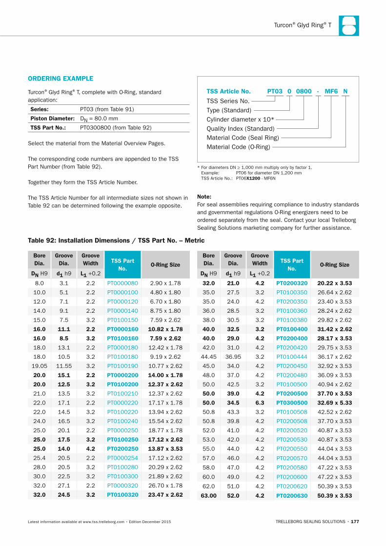
Turcon® Glyd Ring® T
TRELLEBORG SEALING SOLUTIONS • 177Latest information available at www.tss.trelleborg.com • Edition December 2015
Bore Dia.
Groove Dia.
Groove Width TSS Part
no. O-Ring Size
Dn H9 d1 h9 L1 +0.2
8.0 3.1 2.2 PT0000080 2.90 x 1.78
10.0 5.1 2.2 PT0000100 4.80 x 1.80
12.0 7.1 2.2 PT0000120 6.70 x 1.80
14.0 9.1 2.2 PT0000140 8.75 x 1.80
15.0 7.5 3.2 PT0100150 7.59 x 2.62
16.0 11.1 2.2 PT0000160 10.82 x 1.78
16.0 8.5 3.2 PT0100160 7.59 x 2.62
18.0 13.1 2.2 PT0000180 12.42 x 1.78
18.0 10.5 3.2 PT0100180 9.19 x 2.62
19.05 11.55 3.2 PT0100190 10.77 x 2.62
20.0 15.1 2.2 PT0000200 14.00 x 1.78
20.0 12.5 3.2 PT0100200 12.37 x 2.62
21.0 13.5 3.2 PT0100210 12.37 x 2.62
22.0 17.1 2.2 PT0000220 17.17 x 1.78
22.0 14.5 3.2 PT0100220 13.94 x 2.62
24.0 16.5 3.2 PT0100240 15.54 x 2.62
25.0 20.1 2.2 PT0000250 18.77 x 1.78
25.0 17.5 3.2 PT0100250 17.12 x 2.62
25.0 14.0 4.2 PT0200250 13.87 x 3.53
25.4 20.5 2.2 PT0000254 17.12 x 2.62
28.0 20.5 3.2 PT0100280 20.29 x 2.62
30.0 22.5 3.2 PT0100300 21.89 x 2.62
32.0 27.1 2.2 PT0000320 26.70 x 1.78
32.0 24.5 3.2 PT0100320 23.47 x 2.62
Bore Dia.
Groove Dia.
Groove Width TSS Part
no. O-Ring Size
Dn H9 d1 h9 L1 +0.2
32.0 21.0 4.2 PT0200320 20.22 x 3.53
35.0 27.5 3.2 PT0100350 26.64 x 2.62
35.0 24.0 4.2 PT0200350 23.40 x 3.53
36.0 28.5 3.2 PT0100360 28.24 x 2.62
38.0 30.5 3.2 PT0100380 29.82 x 2.62
40.0 32.5 3.2 PT0100400 31.42 x 2.62
40.0 29.0 4.2 PT0200400 28.17 x 3.53
42.0 31.0 4.2 PT0200420 29.75 x 3.53
44.45 36.95 3.2 PT0100444 36.17 x 2.62
45.0 34.0 4.2 PT0200450 32.92 x 3.53
48.0 37.0 4.2 PT0200480 36.09 x 3.53
50.0 42.5 3.2 PT0100500 40.94 x 2.62
50.0 39.0 4.2 PT0200500 37.70 x 3.53
50.0 34.5 6.3 PT0300500 32.69 x 5.33
50.8 43.3 3.2 PT0100508 42.52 x 2.62
50.8 39.8 4.2 PT0200508 37.70 x 3.53
52.0 41.0 4.2 PT0200520 40.87 x 3.53
53.0 42.0 4.2 PT0200530 40.87 x 3.53
55.0 44.0 4.2 PT0200550 44.04 x 3.53
57.0 46.0 4.2 PT0200570 44.04 x 3.53
58.0 47.0 4.2 PT0200580 47.22 x 3.53
60.0 49.0 4.2 PT0200600 47.22 x 3.53
62.0 51.0 4.2 PT0200620 50.39 x 3.53
63.00 52.0 4.2 PT0200630 50.39 x 3.53
Table 92: Installation Dimensions / TSS Part no. – Metric
ORDERInG ExAMPLE
Turcon® Glyd Ring® T, complete with O-Ring, standard application:
Series: PT03 (from Table 91)
Piston Diameter: DN = 80.0 mm
TSS Part no.: PT0300800 (from Table 92)
Select the material from the Material Overview Pages.
The corresponding code numbers are appended to the TSS Part Number (from Table 92).
Together they form the TSS Article Number.
The TSS Article Number for all intermediate sizes not shown in Table 92 can be determined following the example opposite.
Material Code (Seal Ring)
TSS Series No.
TSS Article No.
Material Code (O-Ring)
Cylinder diameter x 10*Quality Index (Standard)
Type (Standard)
MF6 NPT03 -0 0800
* For diameters DN ≥ 1,000 mm multiply only by factor 1. Example: PT06 for diameter DN 1,200 mm TSS Article No.: PT06x1200 - MF6N
note:For seal assemblies requiring compliance to industry standards and governmental regulations O-Ring energizers need to be ordered separately from the seal. Contact your local Trelleborg Sealing Solutions marketing company for further assistance.
FBP_neues_Layout_2015.indb 177 17.10.2016 13:36:54
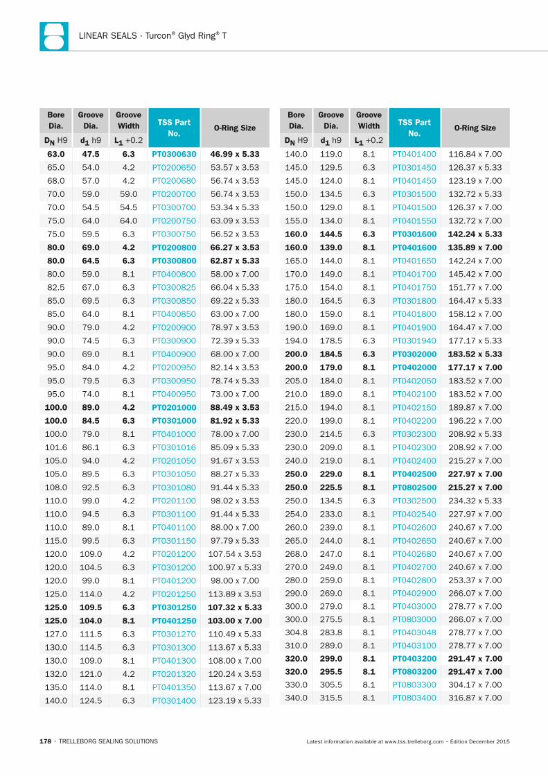
LINEAR SEALS · Turcon® Glyd Ring® T
178 • TRELLEBORG SEALING SOLUTIONS Latest information available at www.tss.trelleborg.com • Edition December 2015
Bore Dia.
Groove Dia.
Groove Width TSS Part
no. O-Ring Size
Dn H9 d1 h9 L1 +0.2
63.0 47.5 6.3 PT0300630 46.99 x 5.33
65.0 54.0 4.2 PT0200650 53.57 x 3.53
68.0 57.0 4.2 PT0200680 56.74 x 3.53
70.0 59.0 59.0 PT0200700 56.74 x 3.53
70.0 54.5 54.5 PT0300700 53.34 x 5.33
75.0 64.0 64.0 PT0200750 63.09 x 3.53
75.0 59.5 6.3 PT0300750 56.52 x 3.53
80.0 69.0 4.2 PT0200800 66.27 x 3.53
80.0 64.5 6.3 PT0300800 62.87 x 5.33
80.0 59.0 8.1 PT0400800 58.00 x 7.00
82.5 67.0 6.3 PT0300825 66.04 x 5.33
85.0 69.5 6.3 PT0300850 69.22 x 5.33
85.0 64.0 8.1 PT0400850 63.00 x 7.00
90.0 79.0 4.2 PT0200900 78.97 x 3.53
90.0 74.5 6.3 PT0300900 72.39 x 5.33
90.0 69.0 8.1 PT0400900 68.00 x 7.00
95.0 84.0 4.2 PT0200950 82.14 x 3.53
95.0 79.5 6.3 PT0300950 78.74 x 5.33
95.0 74.0 8.1 PT0400950 73.00 x 7.00
100.0 89.0 4.2 PT0201000 88.49 x 3.53
100.0 84.5 6.3 PT0301000 81.92 x 5.33
100.0 79.0 8.1 PT0401000 78.00 x 7.00
101.6 86.1 6.3 PT0301016 85.09 x 5.33
105.0 94.0 4.2 PT0201050 91.67 x 3.53
105.0 89.5 6.3 PT0301050 88.27 x 5.33
108.0 92.5 6.3 PT0301080 91.44 x 5.33
110.0 99.0 4.2 PT0201100 98.02 x 3.53
110.0 94.5 6.3 PT0301100 91.44 x 5.33
110.0 89.0 8.1 PT0401100 88.00 x 7.00
115.0 99.5 6.3 PT0301150 97.79 x 5.33
120.0 109.0 4.2 PT0201200 107.54 x 3.53
120.0 104.5 6.3 PT0301200 100.97 x 5.33
120.0 99.0 8.1 PT0401200 98.00 x 7.00
125.0 114.0 4.2 PT0201250 113.89 x 3.53
125.0 109.5 6.3 PT0301250 107.32 x 5.33
125.0 104.0 8.1 PT0401250 103.00 x 7.00
127.0 111.5 6.3 PT0301270 110.49 x 5.33
130.0 114.5 6.3 PT0301300 113.67 x 5.33
130.0 109.0 8.1 PT0401300 108.00 x 7.00
132.0 121.0 4.2 PT0201320 120.24 x 3.53
135.0 114.0 8.1 PT0401350 113.67 x 7.00
140.0 124.5 6.3 PT0301400 123.19 x 5.33
Bore Dia.
Groove Dia.
Groove Width TSS Part
no. O-Ring Size
Dn H9 d1 h9 L1 +0.2
140.0 119.0 8.1 PT0401400 116.84 x 7.00
145.0 129.5 6.3 PT0301450 126.37 x 5.33
145.0 124.0 8.1 PT0401450 123.19 x 7.00
150.0 134.5 6.3 PT0301500 132.72 x 5.33
150.0 129.0 8.1 PT0401500 126.37 x 7.00
155.0 134.0 8.1 PT0401550 132.72 x 7.00
160.0 144.5 6.3 PT0301600 142.24 x 5.33
160.0 139.0 8.1 PT0401600 135.89 x 7.00
165.0 144.0 8.1 PT0401650 142.24 x 7.00
170.0 149.0 8.1 PT0401700 145.42 x 7.00
175.0 154.0 8.1 PT0401750 151.77 x 7.00
180.0 164.5 6.3 PT0301800 164.47 x 5.33
180.0 159.0 8.1 PT0401800 158.12 x 7.00
190.0 169.0 8.1 PT0401900 164.47 x 7.00
194.0 178.5 6.3 PT0301940 177.17 x 5.33
200.0 184.5 6.3 PT0302000 183.52 x 5.33
200.0 179.0 8.1 PT0402000 177.17 x 7.00
205.0 184.0 8.1 PT0402050 183.52 x 7.00
210.0 189.0 8.1 PT0402100 183.52 x 7.00
215.0 194.0 8.1 PT0402150 189.87 x 7.00
220.0 199.0 8.1 PT0402200 196.22 x 7.00
230.0 214.5 6.3 PT0302300 208.92 x 5.33
230.0 209.0 8.1 PT0402300 208.92 x 7.00
240.0 219.0 8.1 PT0402400 215.27 x 7.00
250.0 229.0 8.1 PT0402500 227.97 x 7.00
250.0 225.5 8.1 PT0802500 215.27 x 7.00
250.0 134.5 6.3 PT0302500 234.32 x 5.33
254.0 233.0 8.1 PT0402540 227.97 x 7.00
260.0 239.0 8.1 PT0402600 240.67 x 7.00
265.0 244.0 8.1 PT0402650 240.67 x 7.00
268.0 247.0 8.1 PT0402680 240.67 x 7.00
270.0 249.0 8.1 PT0402700 240.67 x 7.00
280.0 259.0 8.1 PT0402800 253.37 x 7.00
290.0 269.0 8.1 PT0402900 266.07 x 7.00
300.0 279.0 8.1 PT0403000 278.77 x 7.00
300.0 275.5 8.1 PT0803000 266.07 x 7.00
304.8 283.8 8.1 PT0403048 278.77 x 7.00
310.0 289.0 8.1 PT0403100 278.77 x 7.00
320.0 299.0 8.1 PT0403200 291.47 x 7.00
320.0 295.5 8.1 PT0803200 291.47 x 7.00
330.0 305.5 8.1 PT0803300 304.17 x 7.00
340.0 315.5 8.1 PT0803400 316.87 x 7.00
FBP_neues_Layout_2015.indb 178 17.10.2016 13:36:54
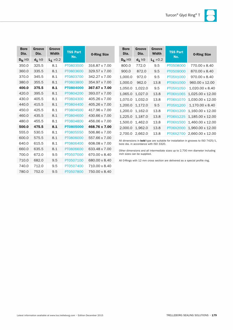
Turcon® Glyd Ring® T
TRELLEBORG SEALING SOLUTIONS • 179Latest information available at www.tss.trelleborg.com • Edition December 2015
Bore Dia.
Groove Dia.
Groove Width TSS Part
no. O-Ring Size
Dn H9 d1 h9 L1 +0.2
350.0 325.5 8.1 PT0803500 316.87 x 7.00
360.0 335.5 8.1 PT0803600 329.57 x 7.00
370.0 345.5 8.1 PT0803700 342.27 x 7.00
380.0 355.5 8.1 PT0803800 354.97 x 7.00
400.0 375.5 8.1 PT0804000 367.67 x 7.00
420.0 395.5 8.1 PT0804200 393.07 x 7.00
430.0 405.5 8.1 PT0804300 405.26 x 7.00
440.0 415.5 8.1 PT0804400 405.26 x 7.00
450.0 425.5 8.1 PT0804500 417.96 x 7.00
460.0 435.5 8.1 PT0804600 430.66 x 7.00
480.0 455.5 8.1 PT0804800 456.06 x 7.00
500.0 475.5 8.1 PT0805000 468.76 x 7.00
555.0 530.5 8.1 PT0805550 506.86 x 7.00
600.0 575.5 8.1 PT0806000 557.66 x 7.00
640.0 615.5 8.1 PT0806400 608.08 x 7.00
660.0 635.5 8.1 PT0806600 633.48 x 7.00
700.0 672.0 9.5 PT0507000 670.00 x 8.40
710.0 682.0 9.5 PT0507100 680.00 x 8.40
740.0 712.0 9.5 PT0507400 710.00 x 8.40
780.0 752.0 9.5 PT0507800 750.00 x 8.40
Bore Dia.
Groove Dia.
Groove Width TSS Part
no. O-Ring Size
Dn H9 d1 h9 L1 +0.2
800.0 772.0 9.5 PT0508000 770.00 x 8.40
900.0 872.0 9.5 PT0509000 870.00 x 8.40
1,000.0 972.0 9.5 PT05X1000 970.00 x 8.40
1,000.0 962.0 13.8 PT06X1000 960.00 x 12.00
1,050.0 1,022.0 9.5 PT05X1050 1,020.00 x 8.40
1,065.0 1,027.0 13.8 PT06X1065 1,025.00 x 12.00
1,070.0 1,032.0 13.8 PT06X1070 1,030.00 x 12.00
1,200.0 1,172.0 9.5 PT05X1200 1,170.00 x 8.40
1,200.0 1,162.0 13.8 PT06X1200 1,160.00 x 12.00
1,225.0 1,187.0 13.8 PT06X1225 1,185.00 x 12.00
1,500.0 1,462.0 13.8 PT06X1500 1,460.00 x 12.00
2,000.0 1,962.0 13.8 PT06X2000 1,960.00 x 12.00
2,700.0 2,662.0 13.8 PT06X2700 2,660.00 x 12.00
All dimensions in bold type are suitable for installation in grooves to ISO 7425/1, bore dia. in accordance with ISO 3320.
Other dimensions and all intermediate sizes up to 2,700 mm diameter including inch sizes can be supplied.
All O-Rings with 12 mm cross section are delivered as a special profile ring.
FBP_neues_Layout_2015.indb 179 17.10.2016 13:36:55
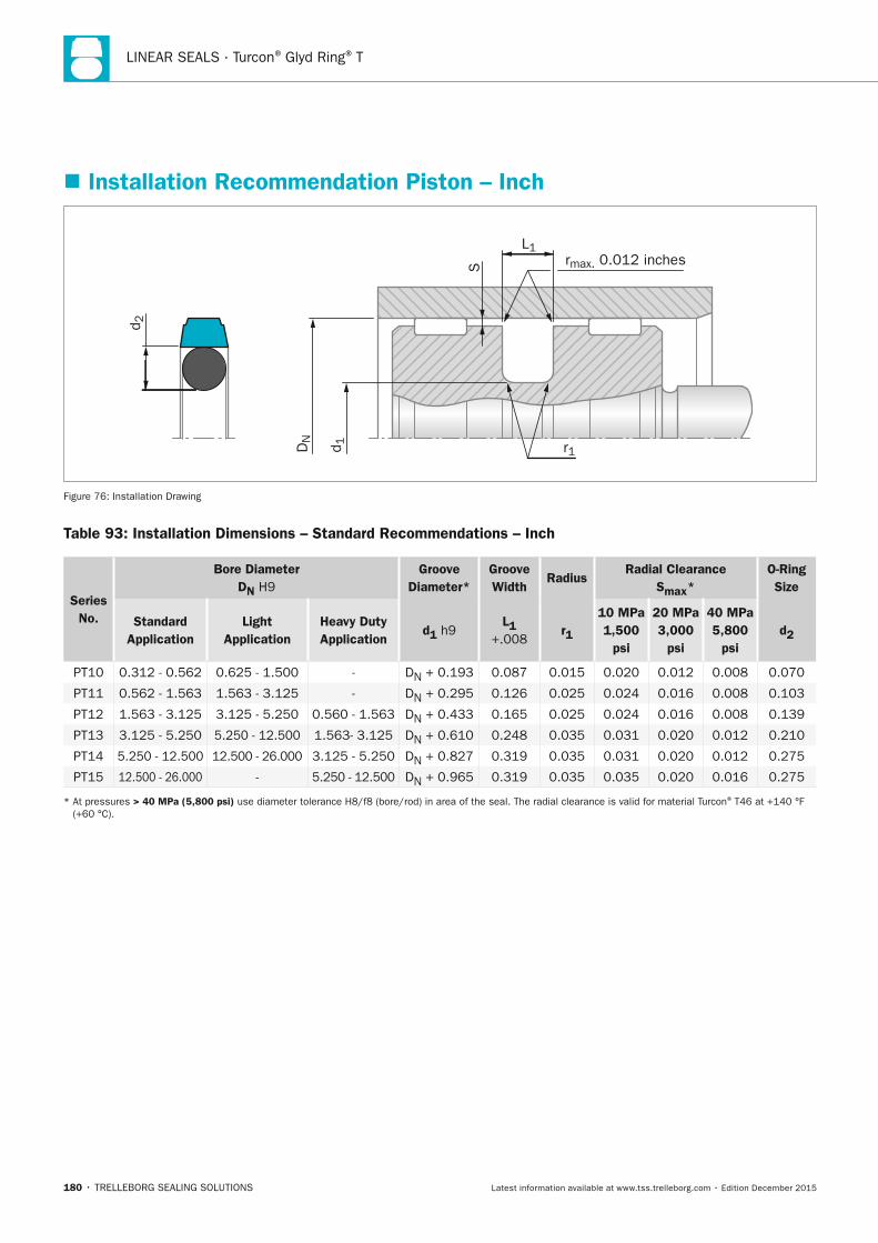
LINEAR SEALS · Turcon® Glyd Ring® T
180 • TRELLEBORG SEALING SOLUTIONS Latest information available at www.tss.trelleborg.com • Edition December 2015
� Installation Recommendation Piston – Inch
rmax. 0.012 inchesS
L1
r1
d 2
DN
d 1
Figure 76: Installation Drawing
Table 93: Installation Dimensions – Standard Recommendations – Inch
Series no.
Bore Diameter Dn H9
Groove Diameter*
Groove Width
RadiusRadial Clearance
Smax*O-Ring Size
Standard Application
Light Application
Heavy Duty Application
d1 h9 L1
+.008 r1
10 MPa 1,500
psi
20 MPa 3,000
psi
40 MPa 5,800
psi d2
PT10 0.312 - 0.562 0.625 - 1.500 - DN + 0.193 0.087 0.015 0.020 0.012 0.008 0.070
PT11 0.562 - 1.563 1.563 - 3.125 - DN + 0.295 0.126 0.025 0.024 0.016 0.008 0.103
PT12 1.563 - 3.125 3.125 - 5.250 0.560 - 1.563 DN + 0.433 0.165 0.025 0.024 0.016 0.008 0.139
PT13 3.125 - 5.250 5.250 - 12.500 1.563- 3.125 DN + 0.610 0.248 0.035 0.031 0.020 0.012 0.210
PT14 5.250 - 12.500 12.500 - 26.000 3.125 - 5.250 DN + 0.827 0.319 0.035 0.031 0.020 0.012 0.275
PT15 12.500 - 26.000 - 5.250 - 12.500 DN + 0.965 0.319 0.035 0.035 0.020 0.016 0.275
* At pressures > 40 MPa (5,800 psi) use diameter tolerance H8/f8 (bore/rod) in area of the seal. The radial clearance is valid for material Turcon® T46 at +140 °F (+60 °C).
FBP_neues_Layout_2015.indb 180 17.10.2016 13:36:55
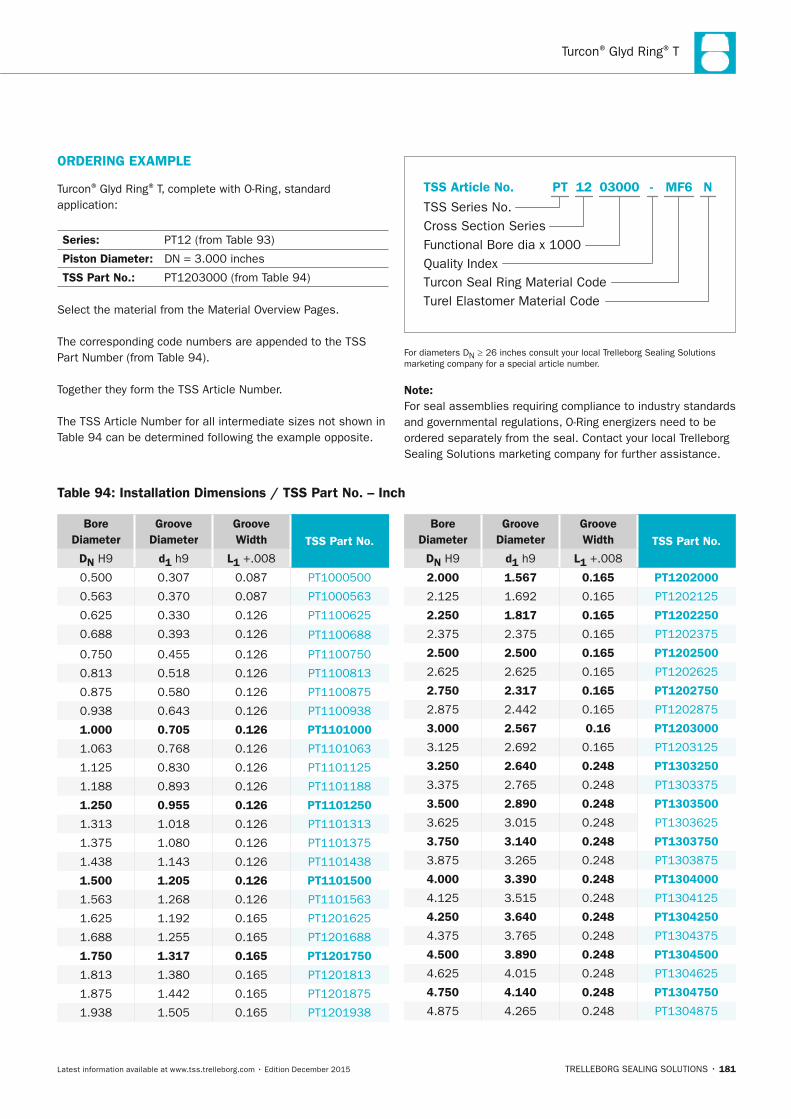
Turcon® Glyd Ring® T
TRELLEBORG SEALING SOLUTIONS • 181Latest information available at www.tss.trelleborg.com • Edition December 2015
Table 94: Installation Dimensions / TSS Part no. – Inch
Bore Diameter
Groove Diameter
Groove Width TSS Part no.
Dn H9 d1 h9 L1 +.008
0.500 0.307 0.087 PT1000500
0.563 0.370 0.087 PT1000563
0.625 0.330 0.126 PT1100625
0.688 0.393 0.126 PT1100688
0.750 0.455 0.126 PT1100750
0.813 0.518 0.126 PT1100813
0.875 0.580 0.126 PT1100875
0.938 0.643 0.126 PT1100938
1.000 0.705 0.126 PT1101000
1.063 0.768 0.126 PT1101063
1.125 0.830 0.126 PT1101125
1.188 0.893 0.126 PT1101188
1.250 0.955 0.126 PT1101250
1.313 1.018 0.126 PT1101313
1.375 1.080 0.126 PT1101375
1.438 1.143 0.126 PT1101438
1.500 1.205 0.126 PT1101500
1.563 1.268 0.126 PT1101563
1.625 1.192 0.165 PT1201625
1.688 1.255 0.165 PT1201688
1.750 1.317 0.165 PT1201750
1.813 1.380 0.165 PT1201813
1.875 1.442 0.165 PT1201875
1.938 1.505 0.165 PT1201938
Bore Diameter
Groove Diameter
Groove Width TSS Part no.
Dn H9 d1 h9 L1 +.008
2.000 1.567 0.165 PT1202000
2.125 1.692 0.165 PT1202125
2.250 1.817 0.165 PT1202250
2.375 2.375 0.165 PT1202375
2.500 2.500 0.165 PT1202500
2.625 2.625 0.165 PT1202625
2.750 2.317 0.165 PT1202750
2.875 2.442 0.165 PT1202875
3.000 2.567 0.16 PT1203000
3.125 2.692 0.165 PT1203125
3.250 2.640 0.248 PT1303250
3.375 2.765 0.248 PT1303375
3.500 2.890 0.248 PT1303500
3.625 3.015 0.248 PT1303625
3.750 3.140 0.248 PT1303750
3.875 3.265 0.248 PT1303875
4.000 3.390 0.248 PT1304000
4.125 3.515 0.248 PT1304125
4.250 3.640 0.248 PT1304250
4.375 3.765 0.248 PT1304375
4.500 3.890 0.248 PT1304500
4.625 4.015 0.248 PT1304625
4.750 4.140 0.248 PT1304750
4.875 4.265 0.248 PT1304875
ORDERInG ExAMPLE
Turcon® Glyd Ring® T, complete with O-Ring, standard application:
Series: PT12 (from Table 93)
Piston Diameter: DN = 3.000 inches
TSS Part no.: PT1203000 (from Table 94)
Select the material from the Material Overview Pages.
The corresponding code numbers are appended to the TSS Part Number (from Table 94).
Together they form the TSS Article Number.
The TSS Article Number for all intermediate sizes not shown in Table 94 can be determined following the example opposite.
Turcon Seal Ring Material Code
TSS Series No.
TSS Article No.
Turel Elastomer Material Code
Functional Bore dia x 1000Quality Index
Cross Section Series
MF6 NPT -12 03000
For diameters DN ≥ 26 inches consult your local Trelleborg Sealing Solutions marketing company for a special article number.
note:For seal assemblies requiring compliance to industry standards and governmental regulations, O-Ring energizers need to be ordered separately from the seal. Contact your local Trelleborg Sealing Solutions marketing company for further assistance.
FBP_neues_Layout_2015.indb 181 17.10.2016 13:36:56
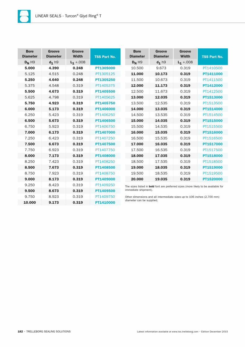
LINEAR SEALS · Turcon® Glyd Ring® T
182 • TRELLEBORG SEALING SOLUTIONS Latest information available at www.tss.trelleborg.com • Edition December 2015
Bore Diameter
Groove Diameter
Groove Width TSS Part no.
Dn H9 d1 h9 L1 +.008
5.000 4.390 0.248 PT1305000
5.125 4.515 0.248 PT1305125
5.250 4.640 0.248 PT1305250
5.375 4.548 0.319 PT1405375
5.500 4.673 0.319 PT1405500
5.625 4.798 0.319 PT1405625
5.750 4.923 0.319 PT1405750
6.000 5.173 0.319 PT1406000
6.250 5.423 0.319 PT1406250
6.500 5.673 0.319 PT1406500
6.750 5.923 0.319 PT1406750
7.000 6.173 0.319 PT1407000
7.250 6.423 0.319 PT1407250
7.500 6.673 0.319 PT1407500
7.750 6.923 0.319 PT1407750
8.000 7.173 0.319 PT1408000
8.250 7.423 0.319 PT1408250
8.500 7.673 0.319 PT1408500
8.750 7.923 0.319 PT1408750
9.000 8.173 0.319 PT1409000
9.250 8.423 0.319 PT1409250
9.500 8.673 0.319 PT1409500
9.750 8.923 0.319 PT1409750
10.000 9.173 0.319 PT1410000
Bore Diameter
Groove Diameter
Groove Width TSS Part no.
Dn H9 d1 h9 L1 +.008
10.500 9.673 0.319 PT1410500
11.000 10.173 0.319 PT1411000
11.500 10.673 0.319 PT1411500
12.000 11.173 0.319 PT1412000
12.500 11.673 0.319 PT1412500
13.000 12.035 0.319 PT1513000
13.500 12.535 0.319 PT1513500
14.000 13.035 0.319 PT1514000
14.500 13.535 0.319 PT1514500
15.000 14.035 0.319 PT1515000
15.500 14.535 0.319 PT1515500
16.000 15.035 0.319 PT1516000
16.500 15.535 0.319 PT1516500
17.000 16.035 0.319 PT1517000
17.500 16.535 0.319 PT1517500
18.000 17.035 0.319 PT1518000
18.500 17.535 0.319 PT1518500
19.000 18.035 0.319 PT1519000
19.500 18.535 0.319 PT1519500
20.000 19.035 0.319 PT1520000
The sizes listed in bold font are preferred sizes (more likely to be available for immediate shipment).
Other dimensions and all intermediate sizes up to 106 inches (2,700 mm) diameter can be supplied.
FBP_neues_Layout_2015.indb 182 17.10.2016 13:36:56
LINEAR SEALS
TRELLEBORG SEALING SOLUTIONS • 183Latest information available at www.tss.trelleborg.com • Edition December 2015
Quad-Ring®
Avoids twisting in the groove
Low friction
Excellent sealing effect
Lubricant reservoir improves start-up
Mold line lies away from critical sealing lips
FBP_neues_Layout_2015.indb 183 17.10.2016 13:36:58

LINEAR SEALS · Quad-Ring®
184 • TRELLEBORG SEALING SOLUTIONS Latest information available at www.tss.trelleborg.com • Edition December 2015
FBP_neues_Layout_2015.indb 184 17.10.2016 13:36:59
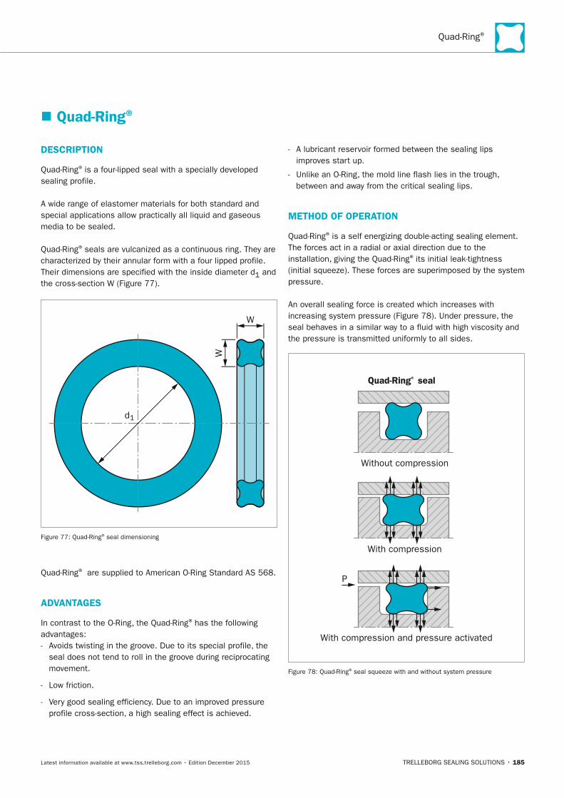
Quad-Ring®
TRELLEBORG SEALING SOLUTIONS • 185Latest information available at www.tss.trelleborg.com • Edition December 2015
� Quad-Ring®
DESCRIPTIOn
Quad-Ring® is a four-lipped seal with a specially developed sealing profile.
A wide range of elastomer materials for both standard and special applications allow practically all liquid and gaseous media to be sealed.
Quad-Ring® seals are vulcanized as a continuous ring. They are characterized by their annular form with a four lipped profile. Their dimensions are specified with the inside diameter d1 and the cross-section W (Figure 77).
d1
W
W
Figure 77: Quad-Ring® seal dimensioning
Quad-Ring® are supplied to American O-Ring Standard AS 568.
ADVAnTAGES
In contrast to the O-Ring, the Quad-Ring® has the following advantages: - Avoids twisting in the groove. Due to its special profile, the
seal does not tend to roll in the groove during reciprocating movement.
- Low friction.
- Very good sealing efficiency. Due to an improved pressure profile cross-section, a high sealing effect is achieved.
- A lubricant reservoir formed between the sealing lips improves start up.
- Unlike an O-Ring, the mold line flash lies in the trough, between and away from the critical sealing lips.
METHOD OF OPERATIOn
Quad-Ring® is a self energizing double-acting sealing element. The forces act in a radial or axial direction due to the installation, giving the Quad-Ring® its initial leak-tightness (initial squeeze). These forces are superimposed by the system pressure.
An overall sealing force is created which increases with increasing system pressure (Figure 78). Under pressure, the seal behaves in a similar way to a fluid with high viscosity and the pressure is transmitted uniformly to all sides.
Quad-Ring® seal
Without compression
With compression
With compression and pressure activated
P
Figure 78: Quad-Ring® seal squeeze with and without system pressure
FBP_neues_Layout_2015.indb 185 17.10.2016 13:36:59
LINEAR SEALS · Quad-Ring®
186 • TRELLEBORG SEALING SOLUTIONS Latest information available at www.tss.trelleborg.com • Edition December 2015
� Applications
FIELDS OF APPLICATIOn
Quad-Ring® can be used for a wide range of different applications.Quad-Ring® is used predominantly for dynamic sealing functions. Its use is always limited by the pressure to be sealed and the velocity.
Dynamic applications - For sealing of reciprocating pistons, rods, plungers, etc.
- For sealing oscillating, rotating or spiral movements on shafts, spindles, rotary transmission leadthroughs, etc.
Static applications - As a radial-static seal, e.g. for bushings, covers, pipes, etc.
- As an axial-static seal, e.g. for flanges, plates, caps, etc.
- As an energizer element for elastomer energized hydraulic seals where there is a risk of the O-Ring twisting.
QUAD-RInG® SEAL FOR ROTARy APPLICATIOn
In applications with small cyclic periods of activity, Quad-Ring® can also be used for sealing rotating shafts. The following points according to the rotary seal principle should be observed.
The rotary seal principle is based on the fact that an elongated elastomer ring contracts when heated (Joule effect). With the normal design criteria, the seal ring inside diameter d1 will be slightly smaller than the shaft diameter, and the heat generated by friction would cause the ring to contract even more. This results in a higher pressure on the rotating shaft so that a lubricating film is prevented from forming under the seal and even higher friction occurs. The result would be increased wear and a premature failure of the seal.
Using the rotary seal principle, this is prevented by the seal ring being selected so that its inside diameter is approximately 2 to 5 percent larger than the shaft diameter to be sealed. The installation in the groove means that the seal ring is compressed radially and is pressed against the shaft by the groove diameter. The seal ring is thus slightly corrugated in the groove, a fact which helps to improve the lubrication.
The rotary seal principle can be neglected at peripheral speeds of less than 0.5 m/s / 98 fpm.
When using the Quad-Ring® as a rotary seal, the use of a suitable surface coating is recommended. Consult the information given in our brochure "Friction-free Running" or contact your local Trelleborg Sealing Solutions marketing company for further details.
TECHnICAL DATA
Quad-Ring® can be used for a wide range of applications. The choice of a suitable material is determined by the temperature, pressure and media. In order to assess the suitability of Quad-Ring® as a sealing element for a given application, the interaction of all the operating parameters have to be taken into consideration.
Working pressure, dynamic application:
Reciprocating up to 5 MPa (725 psi) without Back-up Ringup to 30 MPa (4,450 psi) with Back-up Ring
Rotatingup to 15 MPa (2,175 psi) with Back-up Ring
Working pressure, static application:
up to 5 MPa (725 psi) without Back-up Ringup to 40 MPa (5,800 psi) with Back-up Ring
Speed: Reciprocating: up to 0.5 m/s (98 fpm)
Rotating: briefly up to 2.0 m/s (394 fpm)
Operating temperature range:
depending on material and media resistance, for:General applications, nBR: -30 °C to +100 °C / -22 °F to +212 °F
General applications, FKM: -18 °C to +200 °C / 0° F to +392 °F
When assessing the application criteria, the transient peak, continuous operating temperature and the cyclic duration factor must be taken into consideration. For rotating applications, the increases in temperature due to frictional heat must be taken into account.
Media:With the large range of materials, each with different properties, which are now available, it is possible to seal against practically all liquids, gases and chemicals. Consult the Chemical Compatibility Guide for information on the optimum material for your application or contact your local Trelleborg Sealing Solutions marketing company.
IMPORTAnT nOTE
For more information on the Quad-Ring, see the full Quad-Ring catalog available on the Trelleborg Sealing Solutions website or contact your local Trelleborg Sealing Solutions marketing company. Quad-Ring is a registered trademark of MRC.
FBP_neues_Layout_2015.indb 186 17.10.2016 13:37:00
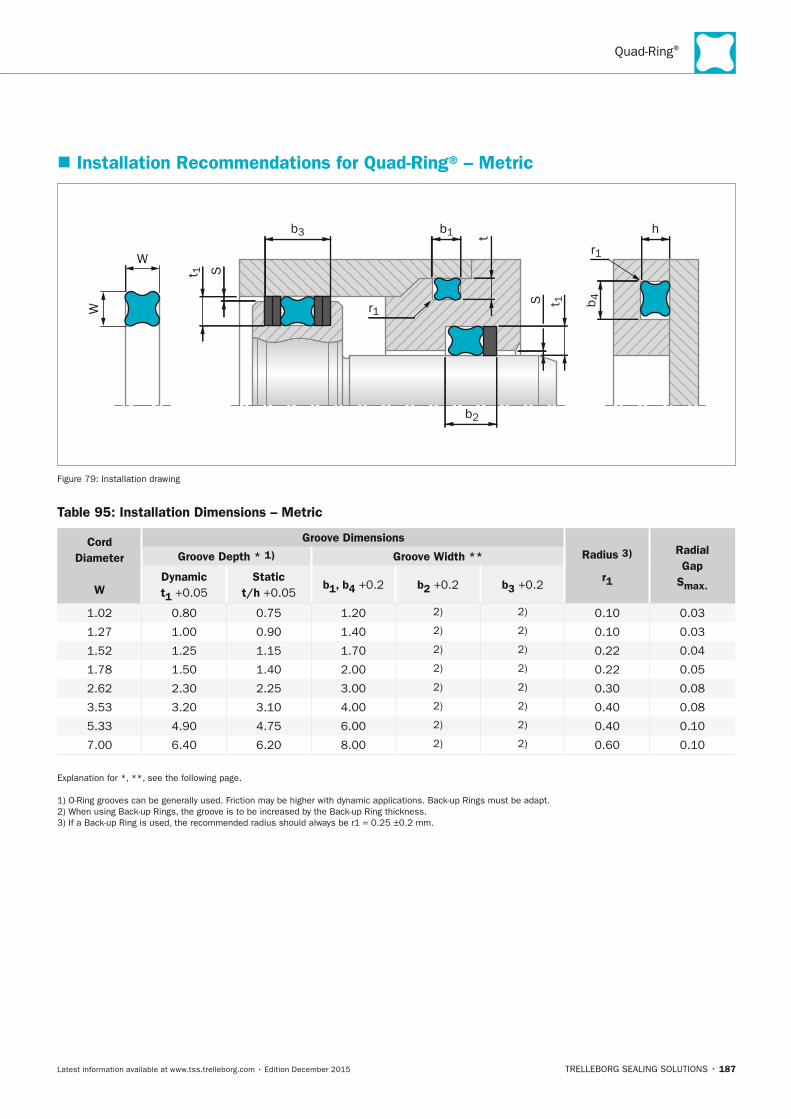
Quad-Ring®
TRELLEBORG SEALING SOLUTIONS • 187Latest information available at www.tss.trelleborg.com • Edition December 2015
� Installation Recommendations for Quad-Ring® – Metric
r1
r1
W
W
t 1
t 1
t
S
S
b3 b1 h
b2
b 4
Figure 79: Installation drawing
Table 95: Installation Dimensions – Metric
Cord Diameter
W
Groove DimensionsRadius 3)
r1
Radial Gap
Smax.
Groove Depth * 1) Groove Width **
Dynamic t1 +0.05
Static t/h +0.05
b1, b4 +0.2 b2 +0.2 b3 +0.2
1.02 0.80 0.75 1.20 2) 2) 0.10 0.03
1.27 1.00 0.90 1.40 2) 2) 0.10 0.03
1.52 1.25 1.15 1.70 2) 2) 0.22 0.04
1.78 1.50 1.40 2.00 2) 2) 0.22 0.05
2.62 2.30 2.25 3.00 2) 2) 0.30 0.08
3.53 3.20 3.10 4.00 2) 2) 0.40 0.08
5.33 4.90 4.75 6.00 2) 2) 0.40 0.10
7.00 6.40 6.20 8.00 2) 2) 0.60 0.10
Explanation for *, **, see the following page.
1) O-Ring grooves can be generally used. Friction may be higher with dynamic applications. Back-up Rings must be adapt. 2) When using Back-up Rings, the groove is to be increased by the Back-up Ring thickness. 3) If a Back-up Ring is used, the recommended radius should always be r1 = 0.25 ±0.2 mm.
FBP_neues_Layout_2015.indb 187 17.10.2016 13:37:00
LINEAR SEALS · Quad-Ring®
188 • TRELLEBORG SEALING SOLUTIONS Latest information available at www.tss.trelleborg.com • Edition December 2015
GEnERAL nOTES
* The values quoted for groove depth are average values and apply under medium load conditions in hydraulic applications. For eccentric piston positions or bending of the rod and in vacuum and low-pressure applications, the groove depth should be reduced and/or the initial squeeze increased.
** If a greater swelling of the seal material is anticipated, the groove width can be increased by up to approximately 20%. The installation dimensions apply to NBR Quad-Ring®
seals. All molds for Quad-Ring® production are designed to compensate for the shrinkage behavior of NBR materials.
Therefore the inside diameter and cross section of Quad-Ring®
seals manufactured from elastomers with a higher shrinkage, such as VMQ or FKM, may differ slightly. FKM Quad-Ring®
seals generally will have slightly smaller dimensions than the corresponding NBR sizes.
Owing to this, in particular cases the groove depth must be adapted, or rather reduced, depending on the application and the nominal sizes of the seal.
As a guide value for the higher shrinkage of FKM materials, a difference of approximately 0.5 % may be assumed. Exact values depend on the material and may deviate from this.
FBP_neues_Layout_2015.indb 188 17.10.2016 13:37:00
ROTARY SEALS
TRELLEBORG SEALING SOLUTIONS • 189Latest information available at www.tss.trelleborg.com • Edition December 2015
RotarySealsRotarySealsRotary
FBP_neues_Layout_2015.indb 189 17.10.2016 13:37:02

190 • TRELLEBORG SEALING SOLUTIONS Latest information available at www.tss.trelleborg.com • Edition December 2015
ROTARY SEALS
FBP_neues_Layout_2015.indb 190 17.10.2016 13:37:02
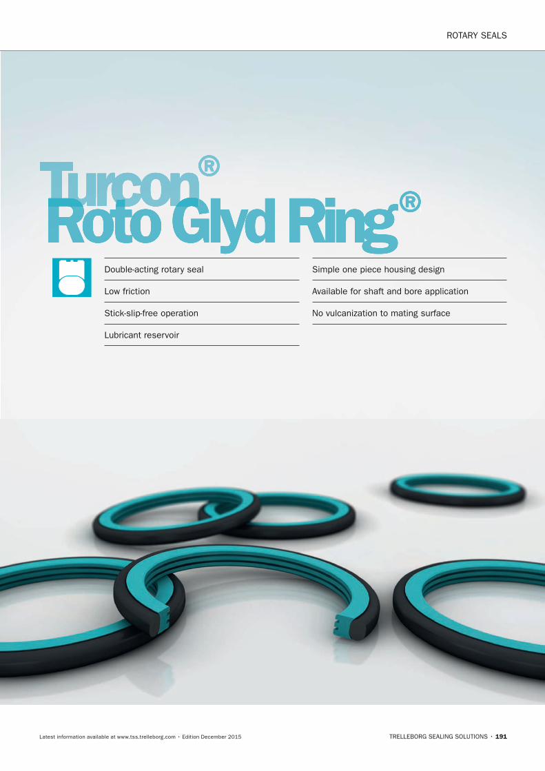
ROTARY SEALS
TRELLEBORG SEALING SOLUTIONS • 191Latest information available at www.tss.trelleborg.com • Edition December 2015
Turcon®Turcon®TurconRoto Glyd RingTurconRoto Glyd RingTurcon ®Double-acting rotary seal
Low friction
Stick-slip-free operation
Lubricant reservoir
Simple one piece housing design
Available for shaft and bore application
No vulcanization to mating surface
FBP_neues_Layout_2015.indb 191 17.10.2016 13:37:04

ROTARY SEALS · Turcon® Roto Glyd Ring®
192 • TRELLEBORG SEALING SOLUTIONS Latest information available at www.tss.trelleborg.com • Edition December 2015
FBP_neues_Layout_2015.indb 192 17.10.2016 13:37:04
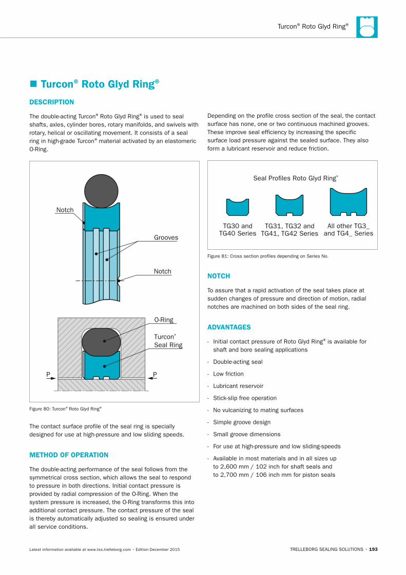
Turcon® Roto Glyd Ring®
TRELLEBORG SEALING SOLUTIONS • 193Latest information available at www.tss.trelleborg.com • Edition December 2015
� Turcon® Roto Glyd Ring®
DESCRIPTIOn
The double-acting Turcon® Roto Glyd Ring® is used to seal shafts, axles, cylinder bores, rotary manifolds, and swivels with rotary, helical or oscillating movement. It consists of a seal ring in high-grade Turcon® material activated by an elastomeric O-Ring.
Notch
Notch
Turcon® Seal Ring
O-Ring
Grooves
PP
Figure 80: Turcon® Roto Glyd Ring®
The contact surface profile of the seal ring is specially designed for use at high-pressure and low sliding speeds.
METHOD OF OPERATIOn
The double-acting performance of the seal follows from the symmetrical cross section, which allows the seal to respond to pressure in both directions. Initial contact pressure is provided by radial compression of the O-Ring. When the system pressure is increased, the O-Ring transforms this into additional contact pressure. The contact pressure of the seal is thereby automatically adjusted so sealing is ensured under all service conditions.
Depending on the profile cross section of the seal, the contact surface has none, one or two continuous machined grooves. These improve seal efficiency by increasing the specific surface load pressure against the sealed surface. They also form a lubricant reservoir and reduce friction.
Seal Pro�les Roto Glyd Ring®
TG30 andTG40 Series
TG31, TG32 andTG41, TG42 Series
All other TG3_ and TG4_ Series
Figure 81: Cross section profiles depending on Series No.
nOTCH
To assure that a rapid activation of the seal takes place at sudden changes of pressure and direction of motion, radial notches are machined on both sides of the seal ring.
ADVAnTAGES
- Initial contact pressure of Roto Glyd Ring® is available for shaft and bore sealing applications
- Double-acting seal
- Low friction
- Lubricant reservoir
- Stick-slip free operation
- No vulcanizing to mating surfaces
- Simple groove design
- Small groove dimensions
- For use at high-pressure and low sliding-speeds
- Available in most materials and in all sizes up to 2,600 mm / 102 inch for shaft seals and to 2,700 mm / 106 inch mm for piston seals
FBP_neues_Layout_2015.indb 193 17.10.2016 13:37:05
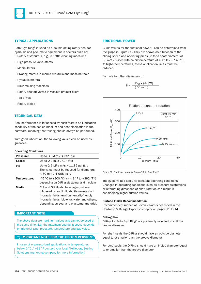
ROTARY SEALS · Turcon® Roto Glyd Ring®
194 • TRELLEBORG SEALING SOLUTIONS Latest information available at www.tss.trelleborg.com • Edition December 2015
FRICTIOnAL POWER
Guide values for the frictional power P can be determined from the graph in Figure 82. They are shown as a function of the sliding speed and operating pressure for a shaft diameter of 50 mm / 2 inch with an oil temperature of +60° C / +140 °F. At higher temperatures, these application limits must be reduced.
Formula for other diameters d:
P = P50 x (d) [W]( 50 mm )
Fric
tiona
l Pow
er P
50 (W
)
Friction at constant rotation
0
100
200
300
400
10Pressure MPa
20 30
1 m/s
0.5 m/s
0.25 m/s
0.15 m/s
Shaft 50 mm60 ºC
Figure 82: Frictional power for Turcon® Roto Glyd Ring®
The guide values apply for constant operating conditions. Changes in operating conditions such as pressure fluctuations or alternating directions of shaft rotation can result in considerably higher friction values.
Surface Finish RecommendationRecommended surface of Piston / Rod is described in the Hardware & Design Expertise chapter on pages 11 to 14.
O-Ring SizeO-Ring for Roto Glyd Ring® are preferably selected to suit the groove diameter:
For shaft seals the O-Ring should have an outside diameter equal to or smaller than the groove diameter.
For bore seals the O-Ring should have an inside diameter equal to or smaller than the groove diameter.
TyPICAL APPLICATIOnS
Roto Glyd Ring® is used as a double acting rotary seal for hydraulic and pneumatic equipment in sectors such as: - Rotary distributors, e.g. in bottle cleaning machines
- High pressure valve stems
- Manipulators
- Pivoting motors in mobile hydraulic and machine tools
- Hydraulic motors
- Blow molding machines
- Rotary shut-off valves in viscous product fillers
- Top drives
- Rotary tables
TECHnICAL DATA
Seal performance is influenced by such factors as lubrication capability of the sealed medium and heat dissipation in the hardware, meaning that testing should always be performed.
With good lubrication, the following values can be used as guidance:
Operating Conditions
Pressure: Up to 30 MPa / 4,351 psi
Speed: Up to 0.2 m/s / 0.7 ft/s
pv: Up to 2.5 MPa m/s / 1,189 psi ft/s The value must be reduced for diameters < 50 mm / 1.968 inch.
Temperature: -45 °C to +200 °C*) / -49 °F to +392 °F*) depending on O-Ring elastomer and medium
Media: CIP and SIP fluids, beverages, mineral oil-based hydraulic fluids, flame-retardant hydraulic fluids, environmentally-friendly hydraulic fluids (bio-oils), water and others, depending on seal and elastomer material.
IMPORTAnT nOTE
The above data are maximum values and cannot be used at the same time. E.g. the maximum operating speed depends on material type, pressure, temperature and gap value.
*) IMPORTAnT nOTE FOR THE PISTOn VERSIOn:
In case of unpressurized applications in temperatures below 0 °C / +32 °F contact your local Trellleborg Sealing Solutions marketing company for more information!
FBP_neues_Layout_2015.indb 194 17.10.2016 13:37:06
Turcon® Roto Glyd Ring®
TRELLEBORG SEALING SOLUTIONS • 195Latest information available at www.tss.trelleborg.com • Edition December 2015
RECOMMEnDED MATERIALS
The following material combinations have proven effective for food, beverage and pharmaceutical fluid applications:
Turcon® Roto Glyd Ring® in Turcon® MF4 All round material choice for Turcon® Roto Glyd Ring® in lubricating fluids and other fluids with limited lubrication e. g. water:
O-Ring: NBR 70 Shore A N HNBR 70 Shore A H (according to temperature media, required approvals and availability)
Set code: MF4N, MF4V or MF4H
Turcon® Roto Glyd Ring® in Turcon® MF6 All round material with high sealing effect for light to medium fluid applications in various fluids with requirements for compliance to various regulations:
O-Ring: NBR 70 Shore A N FKM 70 Shore A V HNBR 70 Shore A H (according to temperature media, required approvals and availability)
Set code: MF6N, MF6V or MF6H
Turcon® Roto Glyd Ring® in Zurcon® Z80 / Z81 For applications with air, gases and risk of high abrasive wear Zurcon® Z80 / Z81 are recommended.
(temperature -45 °C to +80 °C / -49 °F to +176 °F)
O-Ring: NBR 70 Shore A N FKM 70 Shore A V (according to media and required approvals)
Set code: Z80N, Z81N, Z80V or Z81V
Z80 / Z81 are for slow turning motions and not for constant rotation.
Other Turcon® and Zurcon® materials are available on request.
Other O-Ring EPDM 70 Shore A Ematerials: FFKM 75 Shore A J (according to temperature, required approvals
and availability)
Special O-Rings with approvals have to be ordered separately. In this case, the last digit in the material code of the Turcon®
Roto Glyd Ring® becomes obsolete (see table on next page).
Installation of Turcon® Roto Glyd Ring®
The seal is preferably installed in a closed groove. The installation procedure is the same as for a piston or rod seal, see page 21 and 23.
FBP_neues_Layout_2015.indb 195 17.10.2016 13:37:06
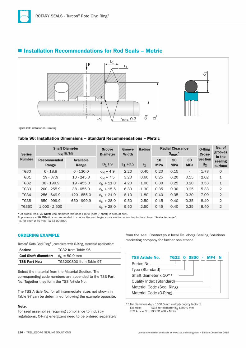
ROTARY SEALS · Turcon® Roto Glyd Ring®
196 • TRELLEBORG SEALING SOLUTIONS Latest information available at www.tss.trelleborg.com • Edition December 2015
� Installation Recommendations for Rod Seals – Metric
L1
S rmax. 0.3
r1
D1
d N
d 2
P
Figure 83: Installation Drawing
Table 96: Installation Dimensions – Standard Recommendations – Metric
Series number
Shaft Diameterdn f8/h9
Groove Diameter
D1 H9
Groove Width
L1 +0.2
Radius r1
Radial ClearanceSmax*
O-Ring Cross-
Sectiond2
no. of grooves in the
sealing surface
Recommended Range
Available Range
10 MPa
20 MPa
30 MPa
TG30 6 - 18.9 6 - 130.0 dN + 4.9 2.20 0.40 0.20 0.15 - 1.78 0
TG31 19 - 37.9 10 - 245.0 dN + 7.5 3.20 0.60 0.25 0.20 0.15 2.62 1
TG32 38 - 199.9 19 - 455.0 dN + 11.0 4.20 1.00 0.30 0.25 0.20 3.53 1
TG33 200 - 255.9 38 - 655.0 dN + 15.5 6.30 1.30 0.35 0.30 0.25 5.33 2
TG34 256 - 649.9 120 - 655.0 dN + 21.0 8.10 1.80 0.40 0.35 0.30 7.00 2
TG35 650 - 999.9 650 - 999.9 dN + 28.0 9.50 2.50 0.45 0.40 0.35 8.40 2
TG35X 1,000 - 2,500 - dN + 28.0 9.50 2.50 0.45 0.40 0.35 8.40 2
* At pressures > 30 MPa: Use diameter tolerance H8/f8 (bore / shaft) in area of seal. At pressures > 10 MPa it is recommended to choose the next larger cross section according to the column “Available range“ i.e. for shaft ø 80 mm: TG 33 00 800-.
ORDERInG ExAMPLE
Turcon® Roto Glyd Ring®, complete with O-Ring, standard application:
Series: TG32 from Table 96
Cod Shaft diameter: dN = 80.0 mm
TSS Part no.: TG3200800 from Table 97
Select the material from the Material Section. The corresponding code numbers are appended to the TSS Part No. Together they form the TSS Article No.
The TSS Article No. for all intermediate sizes not shown in Table 97 can be determined following the example opposite.
note:For seal assemblies requiring compliance to industry regulations, O-Ring energizers need to be ordered separately
from the seal. Contact your local Trelleborg Sealing Solutions marketing company for further assistance.
Material Code (Seal Ring)
Series No.
TSS Article No.
Material Code (O-Ring)
Shaft diameter x 10**Quality Index (Standard)
Type (Standard)
MF4 NTG32 -0 0800
** For diameters dN ≥ 1000.0 mm multiply only by factor 1. Example: TG35 for diameter dN 1200.0 mm TSS Article No.: TG35X1200 – MF4N
FBP_neues_Layout_2015.indb 196 17.10.2016 13:37:07
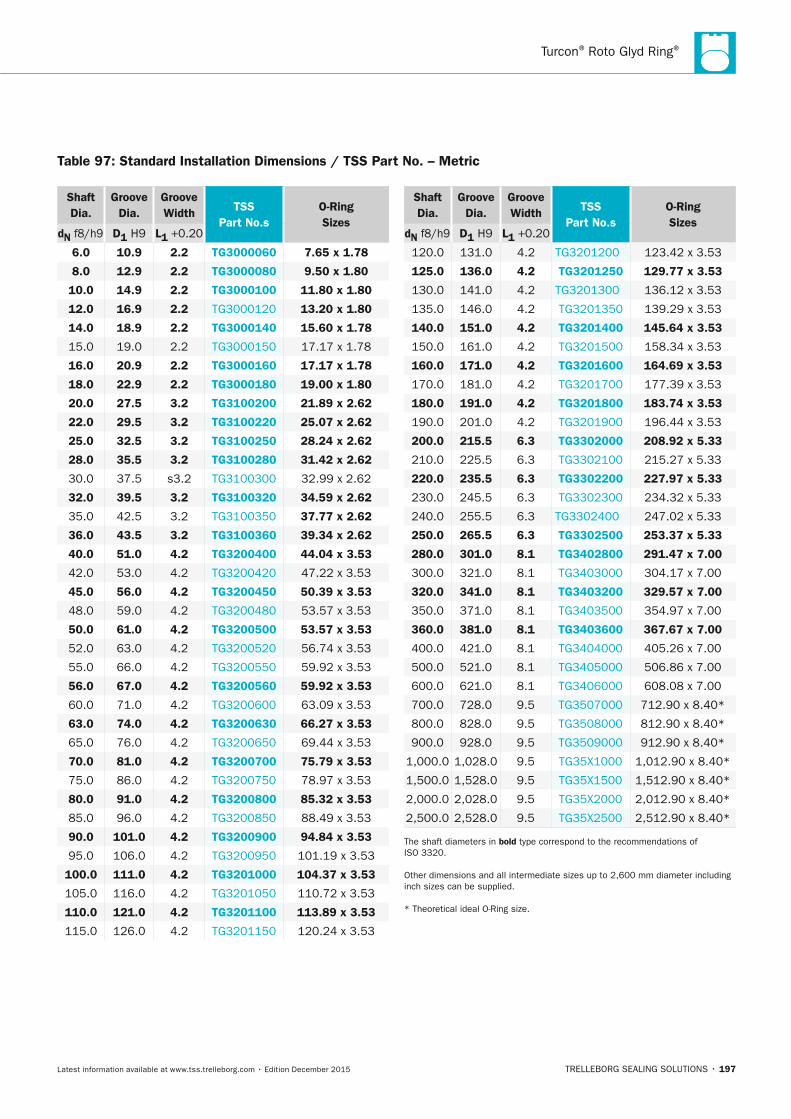
Turcon® Roto Glyd Ring®
TRELLEBORG SEALING SOLUTIONS • 197Latest information available at www.tss.trelleborg.com • Edition December 2015
Shaft Dia.
Groove Dia.
Groove Width TSS
Part no.sO-Ring Sizes
dn f8/h9 D1 H9 L1 +0.20
6.0 10.9 2.2 TG3000060 7.65 x 1.78
8.0 12.9 2.2 TG3000080 9.50 x 1.80
10.0 14.9 2.2 TG3000100 11.80 x 1.80
12.0 16.9 2.2 TG3000120 13.20 x 1.80
14.0 18.9 2.2 TG3000140 15.60 x 1.78
15.0 19.0 2.2 TG3000150 17.17 x 1.78
16.0 20.9 2.2 TG3000160 17.17 x 1.78
18.0 22.9 2.2 TG3000180 19.00 x 1.80
20.0 27.5 3.2 TG3100200 21.89 x 2.62
22.0 29.5 3.2 TG3100220 25.07 x 2.62
25.0 32.5 3.2 TG3100250 28.24 x 2.62
28.0 35.5 3.2 TG3100280 31.42 x 2.62
30.0 37.5 s3.2 TG3100300 32.99 x 2.62
32.0 39.5 3.2 TG3100320 34.59 x 2.62
35.0 42.5 3.2 TG3100350 37.77 x 2.62
36.0 43.5 3.2 TG3100360 39.34 x 2.62
40.0 51.0 4.2 TG3200400 44.04 x 3.53
42.0 53.0 4.2 TG3200420 47.22 x 3.53
45.0 56.0 4.2 TG3200450 50.39 x 3.53
48.0 59.0 4.2 TG3200480 53.57 x 3.53
50.0 61.0 4.2 TG3200500 53.57 x 3.53
52.0 63.0 4.2 TG3200520 56.74 x 3.53
55.0 66.0 4.2 TG3200550 59.92 x 3.53
56.0 67.0 4.2 TG3200560 59.92 x 3.53
60.0 71.0 4.2 TG3200600 63.09 x 3.53
63.0 74.0 4.2 TG3200630 66.27 x 3.53
65.0 76.0 4.2 TG3200650 69.44 x 3.53
70.0 81.0 4.2 TG3200700 75.79 x 3.53
75.0 86.0 4.2 TG3200750 78.97 x 3.53
80.0 91.0 4.2 TG3200800 85.32 x 3.53
85.0 96.0 4.2 TG3200850 88.49 x 3.53
90.0 101.0 4.2 TG3200900 94.84 x 3.53
95.0 106.0 4.2 TG3200950 101.19 x 3.53
100.0 111.0 4.2 TG3201000 104.37 x 3.53
105.0 116.0 4.2 TG3201050 110.72 x 3.53
110.0 121.0 4.2 TG3201100 113.89 x 3.53
115.0 126.0 4.2 TG3201150 120.24 x 3.53
Shaft Dia.
Groove Dia.
Groove Width TSS
Part no.sO-Ring Sizes
dn f8/h9 D1 H9 L1 +0.20
120.0 131.0 4.2 TG3201200 123.42 x 3.53
125.0 136.0 4.2 TG3201250 129.77 x 3.53
130.0 141.0 4.2 TG3201300 136.12 x 3.53
135.0 146.0 4.2 TG3201350 139.29 x 3.53
140.0 151.0 4.2 TG3201400 145.64 x 3.53
150.0 161.0 4.2 TG3201500 158.34 x 3.53
160.0 171.0 4.2 TG3201600 164.69 x 3.53
170.0 181.0 4.2 TG3201700 177.39 x 3.53
180.0 191.0 4.2 TG3201800 183.74 x 3.53
190.0 201.0 4.2 TG3201900 196.44 x 3.53
200.0 215.5 6.3 TG3302000 208.92 x 5.33
210.0 225.5 6.3 TG3302100 215.27 x 5.33
220.0 235.5 6.3 TG3302200 227.97 x 5.33
230.0 245.5 6.3 TG3302300 234.32 x 5.33
240.0 255.5 6.3 TG3302400 247.02 x 5.33
250.0 265.5 6.3 TG3302500 253.37 x 5.33
280.0 301.0 8.1 TG3402800 291.47 x 7.00
300.0 321.0 8.1 TG3403000 304.17 x 7.00
320.0 341.0 8.1 TG3403200 329.57 x 7.00
350.0 371.0 8.1 TG3403500 354.97 x 7.00
360.0 381.0 8.1 TG3403600 367.67 x 7.00
400.0 421.0 8.1 TG3404000 405.26 x 7.00
500.0 521.0 8.1 TG3405000 506.86 x 7.00
600.0 621.0 8.1 TG3406000 608.08 x 7.00
700.0 728.0 9.5 TG3507000 712.90 x 8.40*
800.0 828.0 9.5 TG3508000 812.90 x 8.40*
900.0 928.0 9.5 TG3509000 912.90 x 8.40*
1,000.0 1,028.0 9.5 TG35X1000 1,012.90 x 8.40*
1,500.0 1,528.0 9.5 TG35X1500 1,512.90 x 8.40*
2,000.0 2,028.0 9.5 TG35X2000 2,012.90 x 8.40*
2,500.0 2,528.0 9.5 TG35X2500 2,512.90 x 8.40*
The shaft diameters in bold type correspond to the recommendations of ISO 3320.
Other dimensions and all intermediate sizes up to 2,600 mm diameter including inch sizes can be supplied.
* Theoretical ideal O-Ring size.
Table 97: Standard Installation Dimensions / TSS Part no. – Metric
FBP_neues_Layout_2015.indb 197 17.10.2016 13:37:07
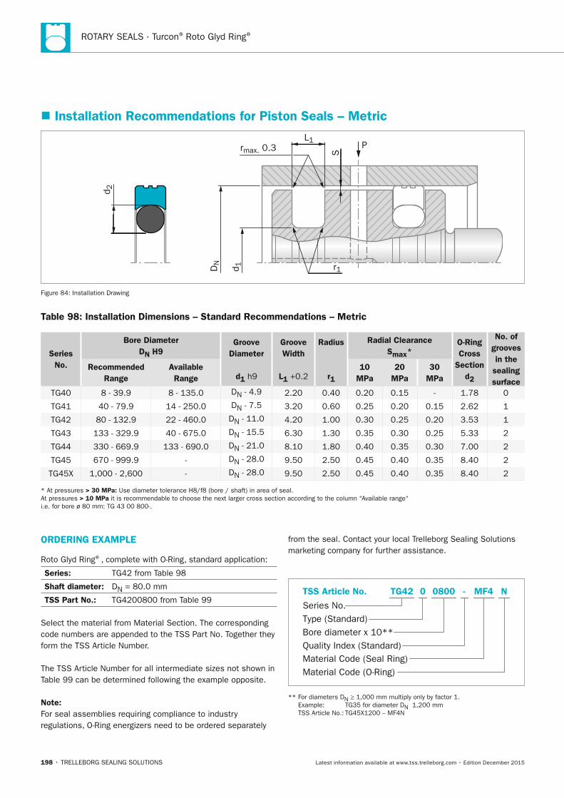
ROTARY SEALS · Turcon® Roto Glyd Ring®
198 • TRELLEBORG SEALING SOLUTIONS Latest information available at www.tss.trelleborg.com • Edition December 2015
� Installation Recommendations for Piston Seals – Metric
P
S
L1rmax. 0.3
r1
d 2
DN
d 1
Figure 84: Installation Drawing
Table 98: Installation Dimensions – Standard Recommendations – Metric
Series no.
Bore Diameter Dn H9
Groove Diameter
d1 h9
Groove Width
L1 +0.2
Radius
r1
Radial ClearanceSmax*
O-Ring Cross
Section d2
no. of grooves in the
sealing surface
Recommended Range
Available
Range 10
MPa 20
MPa 30
MPa
TG40 8 - 39.9 8 - 135.0 DN - 4.9 2.20 0.40 0.20 0.15 - 1.78 0
TG41 40 - 79.9 14 - 250.0 DN - 7.5 3.20 0.60 0.25 0.20 0.15 2.62 1
TG42 80 - 132.9 22 - 460.0 DN - 11.0 4.20 1.00 0.30 0.25 0.20 3.53 1
TG43 133 - 329.9 40 - 675.0 DN - 15.5 6.30 1.30 0.35 0.30 0.25 5.33 2
TG44 330 - 669.9 133 - 690.0 DN - 21.0 8.10 1.80 0.40 0.35 0.30 7.00 2
TG45 670 - 999.9 - DN - 28.0 9.50 2.50 0.45 0.40 0.35 8.40 2
TG45X 1,000 - 2,600 - DN - 28.0 9.50 2.50 0.45 0.40 0.35 8.40 2
* At pressures > 30 MPa: Use diameter tolerance H8/f8 (bore / shaft) in area of seal. At pressures > 10 MPa it is recommendable to choose the next larger cross section according to the column “Available range“ i.e. for bore ø 80 mm: TG 43 00 800-.
ORDERInG ExAMPLE
Roto Glyd Ring®, complete with O-Ring, standard application:
Series: TG42 from Table 98
Shaft diameter: DN = 80.0 mm
TSS Part no.: TG4200800 from Table 99
Select the material from Material Section. The corresponding code numbers are appended to the TSS Part No. Together they form the TSS Article Number.
The TSS Article Number for all intermediate sizes not shown in Table 99 can be determined following the example opposite.
note:For seal assemblies requiring compliance to industry regulations, O-Ring energizers need to be ordered separately
from the seal. Contact your local Trelleborg Sealing Solutions marketing company for further assistance.
Material Code (Seal Ring)
Series No.
TSS Article No.
Material Code (O-Ring)
Bore diameter x 10**Quality Index (Standard)
Type (Standard)
MF4 NTG42 -0 0800
** For diameters DN ≥ 1,000 mm multiply only by factor 1. Example: TG35 for diameter DN 1,200 mm TSS Article No.: TG45X1200 – MF4N
FBP_neues_Layout_2015.indb 198 17.10.2016 13:37:08
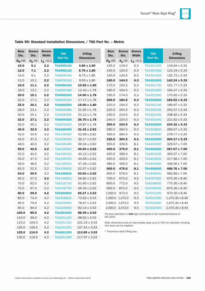
Turcon® Roto Glyd Ring®
TRELLEBORG SEALING SOLUTIONS • 199Latest information available at www.tss.trelleborg.com • Edition December 2015
Bore Dia.
Groove Dia.
Groove Width TSS
Part no.O-Ring
DimensionsDn H9 d1 h9 L1 +0.2
10.0 5.1 2.2 TG4000100 4.80 x 1.80
12.0 7.1 2.2 TG4000120 6.70 x 1.80
14.0 9.1 2.2 TG4000140 8.75 x 1.80
15.0 10.1 2.2 TG4000150 9.50 x 1.80
16.0 11.1 2.2 TG4000160 10.60 x 1.80
18.0 13.1 2.2 TG4000180 12.42 x 1.78
20.0 15.1 2.2 TG4000200 14.00 x 1.78
22.0 17.1 2.2 TG4000220 17.17 x 1.78
25.0 20.1 2.2 TG4000250 19.00 x 1.80
28.0 23.1 2.2 TG4000280 21.95 x 1.78
30.0 25.1 2.2 TG4000300 25.12 x 1.78
32.0 27.1 2.2 TG4000320 26.70 x 1.78
35.0 30.1 2.2 TG4000350 29.87 x 1.78
40.0 32.5 3.2 TG4100400 31.42 x 2.62
42.0 34.5 3.2 TG4100420 32.99 x 2.62
45.0 37.5 3.2 TG4100450 36.17 x 2.62
48.0 40.5 3.2 TG4100480 39.34 x 2.62
50.0 42.5 3.2 TG4100500 40.94 x 2.62
52.0 44.5 3.2 TG4100520 44.12 x 2.62
55.0 47.5 3.2 TG4100550 45.69 x 2.62
56.0 48.5 3.2 TG4100550 47.29 x 2.62
60.0 52.5 3.2 TG4100600 52.07 x 2.62
63.0 55.5 3.2 TG4100630 53.64 x 2.62
65.0 57.5 3.2 TG4100650 56.82 x 2.62
70.0 62.5 3.2 TG4100700 61.60 x 2.62
75.0 67.5 3.2 TG4100750 66.34 x 2.62
80.0 69.0 4.2 TG4200800 66.27 x 3.53
85.0 74.0 4.2 TG4200850 72.62 x 3.53
90.0 79.0 4.2 TG4200900 78.97 x 3.53
95.0 84.0 4.2 TG4200950 82.14 x 3.53
100.0 89.0 4.2 TG4201000 88.49 x 3.53
110.0 99.0 4.2 TG4201100 98.02 x 3.53
115.0 104.0 4.2 TG4201150 101.19 x 3.53
120.0 109.0 4.2 TG4201200 107.54 x 3.53
125.0 114.0 4.2 TG4201250 113.89 x 3.53
130.0 119.0 4.2 TG4201300 117.07 x 3.53
Bore Dia.
Groove Dia.
Groove Width TSS
Part no.O-Ring
DimensionsDn H9 d1 h9 L1 +0.2
135.0 119.5 6.3 TG4301350 116.84 x 5.33
140.0 124.5 6.3 TG4301400 123.19 x 5.33
150.0 134.5 6.3 TG4301500 132.72 x 5.33
160.0 144.5 6.3 TG4301600 142.24 x 5.33
170.0 154.5 6.3 TG4301700 151.77 x 5.33
180.0 164.5 6.3 TG4301800 164.47 x 5.33
190.0 174.5 6.3 TG4301900 170.82 x 5.33
200.0 184.5 6.3 TG4302000 183.52 x 5.33
210.0 194.5 6.3 TG4302100 189.87 x 5.33
220.0 204.5 6.3 TG4302200 202.57 x 5.33
230.0 214.5 6.3 TG4302300 208.92 x 5.33
240.0 224.5 6.3 TG4302400 221.62 x 5.33
250.0 234.5 6.3 TG4302500 234.32 x 5.33
280.0 264.5 6.3 TG4302800 266.07 x 5.33
300.0 284.5 6.3 TG4303000 278.77 x 5.33
320.0 304.5 6.3 TG4303200 304.17 x 5.33
350.0 329.0 8.1 TG4403500 329.57 x 7.00
400.0 379.0 8.1 TG4404000 367.67 x 7.00
420.0 399.0 8.1 TG4404200 393.07 x 7.00
450.0 429.0 8.1 TG4404500 417.96 x 7.00
480.0 459.0 8.1 TG4404800 456.06 x 7.00
500.0 479.0 8.1 TG4405000 468.76 x 7.00
600.0 579.0 8.1 TG4406000 582.68 x 7.00
700.0 672.0 9.5 TG4507000 670.30 x 8.40
800.0 772.0 9.5 TG4508000 770.30 x 8.40
900.0 872.0 9.5 TG4509000 870.30 x 8.40
1,000.0 972.0 9.5 TG45X1000 970.30 x 8.40
1,500.0 1,472.0 9.5 TG45X1500 1,470.30 x 8.40
2,000.0 1,972.0 9.5 TG45X2000 1,970.30 x 8.40
2,500.0 2,472.0 9.5 TG45X2500 2,470.30 x 8.40
The bore diameters in bold type correspond to the recommendations of ISO 3320.
Other dimensions and all intermediate sizes up to 2,700 mm diameter including inch sizes can be supplied.
* Theoretical ideal O-Ring size.
Table 99: Standard Installation Dimensions / TSS Part no. – Metric
FBP_neues_Layout_2015.indb 199 17.10.2016 13:37:09

ROTARY SEALS · Turcon® Roto Glyd Ring®
200 • TRELLEBORG SEALING SOLUTIONS Latest information available at www.tss.trelleborg.com • Edition December 2015
FBP_neues_Layout_2015.indb 200 17.10.2016 13:37:09
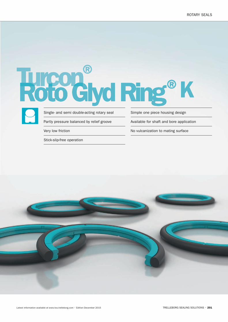
ROTARY SEALS
TRELLEBORG SEALING SOLUTIONS • 201Latest information available at www.tss.trelleborg.com • Edition December 2015
Turcon®Turcon®TurconRoto Glyd RingTurconRoto Glyd RingTurcon ® KSingle- and semi double-acting rotary seal
Partly pressure balanced by relief groove
Very low friction
Stick-slip-free operation
Simple one piece housing design
Available for shaft and bore application
No vulcanization to mating surface
FBP_neues_Layout_2015.indb 201 17.10.2016 13:37:10

ROTARY SEALS · Turcon® Roto Glyd Ring® K
202 • TRELLEBORG SEALING SOLUTIONS Latest information available at www.tss.trelleborg.com • Edition December 2015
FBP_neues_Layout_2015.indb 202 17.10.2016 13:37:11
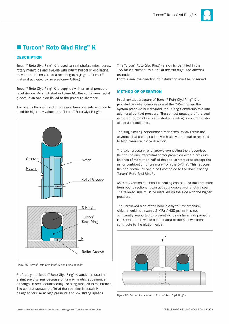
Turcon® Roto Glyd Ring® K
TRELLEBORG SEALING SOLUTIONS • 203Latest information available at www.tss.trelleborg.com • Edition December 2015
� Turcon® Roto Glyd Ring® K
DESCRIPTIOn
Turcon® Roto Glyd Ring® K is used to seal shafts, axles, bores, rotary manifolds and swivels with rotary, helical or oscillating movement. It consists of a seal ring in high-grade Turcon®
material activated by an elastomer O-Ring.
Turcon® Roto Glyd Ring® K is supplied with an axial pressure relief groove. As illustrated in Figure 85, the continuous radial groove is on one side linked to the pressure chamber.
The seal is thus relieved of pressure from one side and can be used for higher pv values than Turcon® Roto Glyd Ring®.
Notch
Relief Groove
Turcon® Seal Ring
O-Ring
Notch
Groove
Relief Groove
P
Figure 85: Turcon® Roto Glyd Ring® K with pressure relief
Preferably the Turcon® Roto Glyd Ring® K version is used as a single-acting seal because of its asymmetric appearance although “a semi double-acting” sealing function is maintained.The contact surface profile of the seal ring is specially designed for use at high pressure and low sliding speeds.
This Turcon® Roto Glyd Ring® version is identified in the TSS Article Number by a “K“ at the 5th digit (see ordering examples).For this seal the direction of installation must be observed.
METHOD OF OPERATIOn
Initial contact pressure of Turcon® Roto Glyd Ring® K is provided by radial compression of the O-Ring. When the system pressure is increased, the O-Ring transforms this into additional contact pressure. The contact pressure of the seal is thereby automatically adjusted so sealing is ensured under all service conditions.
The single-acting performance of the seal follows from the asymmetrical cross section which allows the seal to respond to high pressure in one direction.
The axial pressure relief groove connecting the pressurized fluid to the circumferential center groove ensures a pressure balance of more than half of the seal contact area (except the minor contribution of pressure from the O-Ring). This reduces the seal friction by one a half compared to the double-acting Turcon® Roto Glyd Ring®.
As the K version still has full sealing contact and hold pressure from both directions it can act as a double-acting rotary seal. The relieved side must be installed on the side with the higher pressure.
The unrelieved side of the seal is only for low pressure, which should not exceed 3 MPa / 435 psi as it is not sufficiently supported to prevent extrusion from high pressure. Furthermore, the whole contact area of the seal will then contribute to the friction value.
P
Figure 86: Correct installation of Turcon® Roto Glyd Ring® K
FBP_neues_Layout_2015.indb 203 17.10.2016 13:37:11
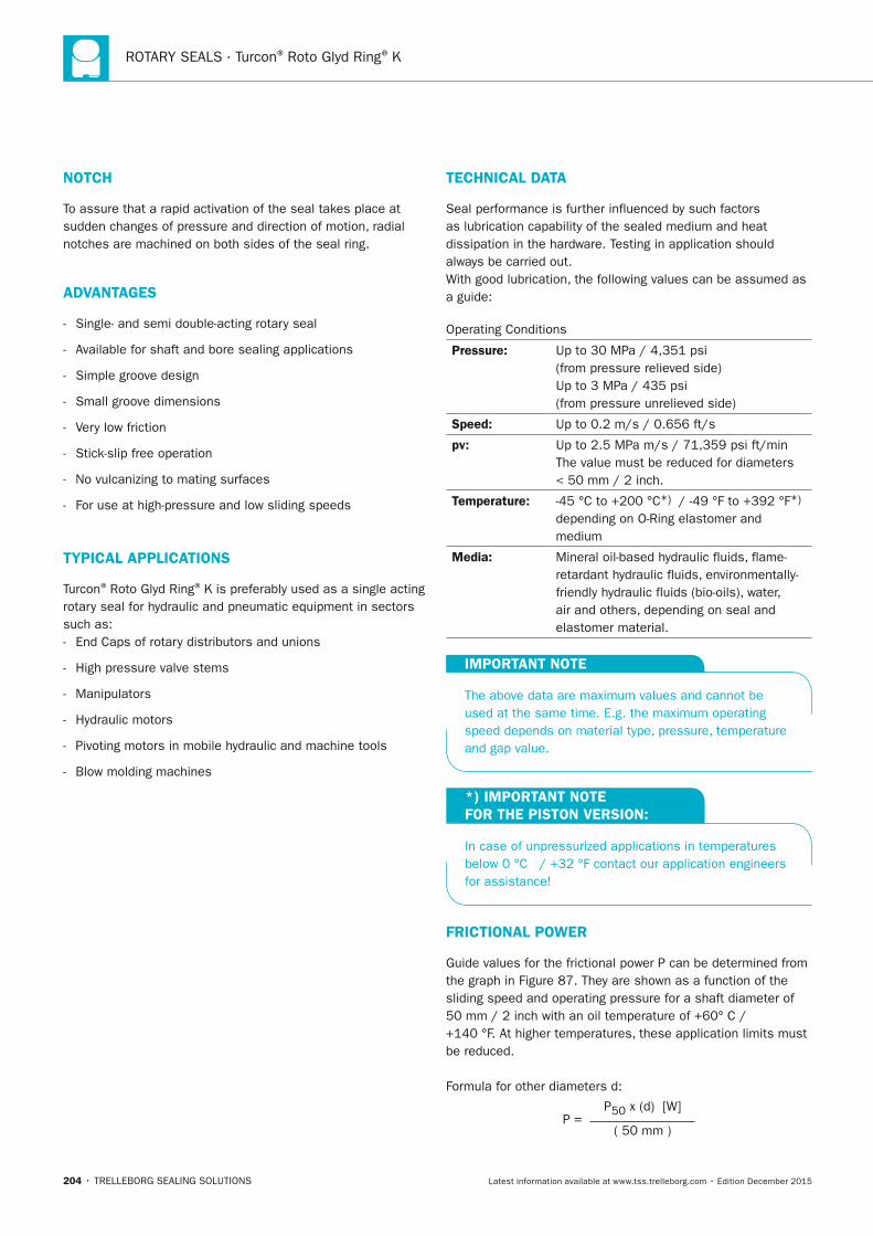
ROTARY SEALS · Turcon® Roto Glyd Ring® K
204 • TRELLEBORG SEALING SOLUTIONS Latest information available at www.tss.trelleborg.com • Edition December 2015
TECHnICAL DATA
Seal performance is further influenced by such factors as lubrication capability of the sealed medium and heat dissipation in the hardware. Testing in application should always be carried out.With good lubrication, the following values can be assumed as a guide:
Operating Conditions
Pressure: Up to 30 MPa / 4,351 psi (from pressure relieved side)Up to 3 MPa / 435 psi (from pressure unrelieved side)
Speed: Up to 0.2 m/s / 0.656 ft/s
pv: Up to 2.5 MPa m/s / 71,359 psi ft/min The value must be reduced for diameters < 50 mm / 2 inch.
Temperature: -45 °C to +200 °C*) / -49 °F to +392 °F*) depending on O-Ring elastomer and medium
Media: Mineral oil-based hydraulic fluids, flame-retardant hydraulic fluids, environmentally-friendly hydraulic fluids (bio-oils), water, air and others, depending on seal and elastomer material.
IMPORTAnT nOTE
The above data are maximum values and cannot be used at the same time. E.g. the maximum operating speed depends on material type, pressure, temperature and gap value.
*) IMPORTAnT nOTE FOR THE PISTOn VERSIOn:
In case of unpressurized applications in temperatures below 0 °C / +32 °F contact our application engineers for assistance!
FRICTIOnAL POWER
Guide values for the frictional power P can be determined from the graph in Figure 87. They are shown as a function of the sliding speed and operating pressure for a shaft diameter of 50 mm / 2 inch with an oil temperature of +60° C / +140 °F. At higher temperatures, these application limits must be reduced.
Formula for other diameters d:
P = P50 x (d) [W]
( 50 mm )
nOTCH
To assure that a rapid activation of the seal takes place at sudden changes of pressure and direction of motion, radial notches are machined on both sides of the seal ring.
ADVAnTAGES
- Single- and semi double-acting rotary seal
- Available for shaft and bore sealing applications
- Simple groove design
- Small groove dimensions
- Very low friction
- Stick-slip free operation
- No vulcanizing to mating surfaces
- For use at high-pressure and low sliding speeds
TyPICAL APPLICATIOnS
Turcon® Roto Glyd Ring® K is preferably used as a single acting rotary seal for hydraulic and pneumatic equipment in sectors such as: - End Caps of rotary distributors and unions
- High pressure valve stems
- Manipulators
- Hydraulic motors
- Pivoting motors in mobile hydraulic and machine tools
- Blow molding machines
FBP_neues_Layout_2015.indb 204 17.10.2016 13:37:12
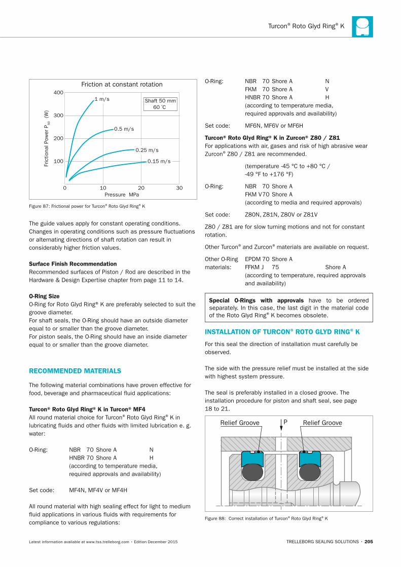
Turcon® Roto Glyd Ring® K
TRELLEBORG SEALING SOLUTIONS • 205Latest information available at www.tss.trelleborg.com • Edition December 2015
Fric
tiona
l Pow
er P
50
(W)
Friction at constant rotation
0
100
200
300
400
10Pressure MPa
20 30
1 m/s
0.5 m/s
0.25 m/s
0.15 m/s
Shaft 50 mm60 ºC
Figure 87: Frictional power for Turcon® Roto Glyd Ring® K
The guide values apply for constant operating conditions. Changes in operating conditions such as pressure fluctuations or alternating directions of shaft rotation can result in considerably higher friction values.
Surface Finish RecommendationRecommended surfaces of Piston / Rod are described in the Hardware & Design Expertise chapter from page 11 to 14.
O-Ring SizeO-Ring for Roto Glyd Ring® K are preferably selected to suit the groove diameter.For shaft seals, the O-Ring should have an outside diameter equal to or smaller than the groove diameter.For piston seals, the O-Ring should have an inside diameter equal to or smaller than the groove diameter.
RECOMMEnDED MATERIALS
The following material combinations have proven effective for food, beverage and pharmaceutical fluid applications:
Turcon® Roto Glyd Ring® K in Turcon® MF4 All round material choice for Turcon® Roto Glyd Ring® K in lubricating fluids and other fluids with limited lubrication e. g. water:
O-Ring: NBR 70 Shore A N HNBR 70 Shore A H (according to temperature media, required approvals and availability)
Set code: MF4N, MF4V or MF4H
All round material with high sealing effect for light to medium fluid applications in various fluids with requirements for compliance to various regulations:
O-Ring: NBR 70 Shore A N FKM 70 Shore A V HNBR 70 Shore A H (according to temperature media, required approvals and availability)
Set code: MF6N, MF6V or MF6H
Turcon® Roto Glyd Ring® K in Zurcon® Z80 / Z81 For applications with air, gases and risk of high abrasive wear Zurcon® Z80 / Z81 are recommended.
(temperature -45 °C to +80 °C / -49 °F to +176 °F)
O-Ring: NBR 70 Shore A FKM V 70 Shore A (according to media and required approvals)
Set code: Z80N, Z81N, Z80V or Z81V
Z80 / Z81 are for slow turning motions and not for constant rotation.
Other Turcon® and Zurcon® materials are available on request.
Other O-Ring EPDM 70 Shore Amaterials: FFKM J 75 Shore A (according to temperature, required approvals
and availability)
Special O-Rings with approvals have to be ordered separately. In this case, the last digit in the material code of the Roto Glyd Ring® K becomes obsolete.
InSTALLATIOn OF TURCOn® ROTO GLyD RInG® K
For this seal the direction of installation must carefully be observed.
The side with the pressure relief must be installed at the side with highest system pressure.
The seal is preferably installed in a closed groove. The installation procedure for piston and shaft seal, see page 18 to 21.
Relief GrooveRelief Groove P
Figure 88: Correct installation of Turcon® Roto Glyd Ring® K
FBP_neues_Layout_2015.indb 205 17.10.2016 13:37:12
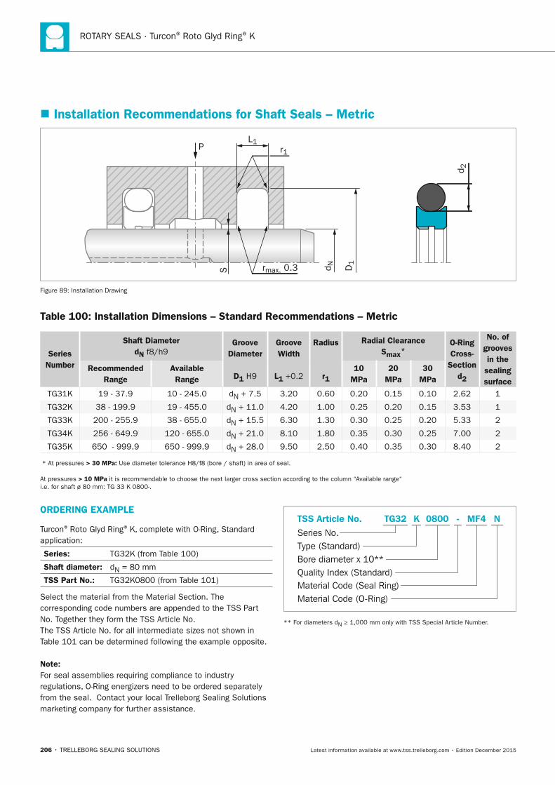
ROTARY SEALS · Turcon® Roto Glyd Ring® K
206 • TRELLEBORG SEALING SOLUTIONS Latest information available at www.tss.trelleborg.com • Edition December 2015
� Installation Recommendations for Shaft Seals – Metric
PL1
S rmax. 0.3
r1
D1
d N
d 2
Figure 89: Installation Drawing
Table 100: Installation Dimensions – Standard Recommendations – Metric
Series number
Shaft Diameterdn f8/h9
Groove Diameter
D1 H9
Groove Width
L1 +0.2
Radius
r1
Radial ClearanceSmax*
O-Ring Cross-
Sectiond2
no. of grooves in the
sealing surface
Recommended Range
Available Range
10 MPa
20 MPa
30 MPa
TG31K 19 - 37.9 10 - 245.0 dN + 7.5 3.20 0.60 0.20 0.15 0.10 2.62 1
TG32K 38 - 199.9 19 - 455.0 dN + 11.0 4.20 1.00 0.25 0.20 0.15 3.53 1
TG33K 200 - 255.9 38 - 655.0 dN + 15.5 6.30 1.30 0.30 0.25 0.20 5.33 2
TG34K 256 - 649.9 120 - 655.0 dN + 21.0 8.10 1.80 0.35 0.30 0.25 7.00 2
TG35K 650 - 999.9 650 - 999.9 dN + 28.0 9.50 2.50 0.40 0.35 0.30 8.40 2
* At pressures > 30 MPa: Use diameter tolerance H8/f8 (bore / shaft) in area of seal.
At pressures > 10 MPa it is recommendable to choose the next larger cross section according to the column “Available range“ i.e. for shaft ø 80 mm: TG 33 K 0800-.
ORDERInG ExAMPLE
Turcon® Roto Glyd Ring® K, complete with O-Ring, Standard application:
Series: TG32K (from Table 100)
Shaft diameter: dN = 80 mm
TSS Part no.: TG32K0800 (from Table 101)
Select the material from the Material Section. The corresponding code numbers are appended to the TSS Part No. Together they form the TSS Article No.The TSS Article No. for all intermediate sizes not shown in Table 101 can be determined following the example opposite.
note: For seal assemblies requiring compliance to industry regulations, O-Ring energizers need to be ordered separately from the seal. Contact your local Trelleborg Sealing Solutions marketing company for further assistance.
Material Code (Seal Ring)
Series No.
TSS Article No.
Material Code (O-Ring)
Bore diameter x 10**Quality Index (Standard)
Type (Standard)
MF4 NTG32 -K 0800
** For diameters dN ≥ 1,000 mm only with TSS Special Article Number.
FBP_neues_Layout_2015.indb 206 17.10.2016 13:37:13
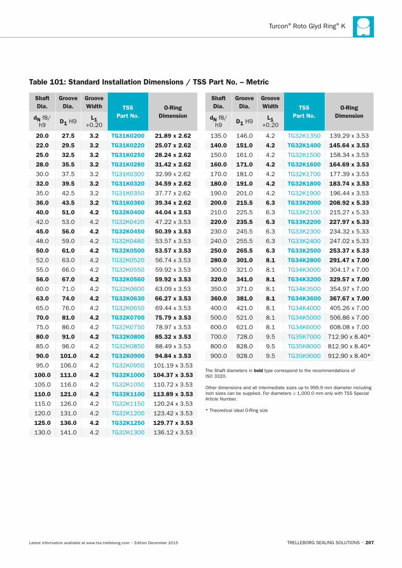
Turcon® Roto Glyd Ring® K
TRELLEBORG SEALING SOLUTIONS • 207Latest information available at www.tss.trelleborg.com • Edition December 2015
Shaft Dia.
Groove Dia.
Groove Width TSS
Part no.O-Ring
Dimensiondn f8/h9
D1 H9L1
+0.20
20.0 27.5 3.2 TG31K0200 21.89 x 2.62
22.0 29.5 3.2 TG31K0220 25.07 x 2.62
25.0 32.5 3.2 TG31K0250 28.24 x 2.62
28.0 35.5 3.2 TG31K0280 31.42 x 2.62
30.0 37.5 3.2 TG31K0300 32.99 x 2.62
32.0 39.5 3.2 TG31K0320 34.59 x 2.62
35.0 42.5 3.2 TG31K0350 37.77 x 2.62
36.0 43.5 3.2 TG31K0360 39.34 x 2.62
40.0 51.0 4.2 TG32K0400 44.04 x 3.53
42.0 53.0 4.2 TG32K0420 47.22 x 3.53
45.0 56.0 4.2 TG32K0450 50.39 x 3.53
48.0 59.0 4.2 TG32K0480 53.57 x 3.53
50.0 61.0 4.2 TG32K0500 53.57 x 3.53
52.0 63.0 4.2 TG32K0520 56.74 x 3.53
55.0 66.0 4.2 TG32K0550 59.92 x 3.53
56.0 67.0 4.2 TG32K0560 59.92 x 3.53
60.0 71.0 4.2 TG32K0600 63.09 x 3.53
63.0 74.0 4.2 TG32K0630 66.27 x 3.53
65.0 76.0 4.2 TG32K0650 69.44 x 3.53
70.0 81.0 4.2 TG32K0700 75.79 x 3.53
75.0 86.0 4.2 TG32K0750 78.97 x 3.53
80.0 91.0 4.2 TG32K0800 85.32 x 3.53
85.0 96.0 4.2 TG32K0850 88.49 x 3.53
90.0 101.0 4.2 TG32K0900 94.84 x 3.53
95.0 106.0 4.2 TG32K0950 101.19 x 3.53
100.0 111.0 4.2 TG32K1000 104.37 x 3.53
105.0 116.0 4.2 TG32K1050 110.72 x 3.53
110.0 121.0 4.2 TG32K1100 113.89 x 3.53
115.0 126.0 4.2 TG32K1150 120.24 x 3.53
120.0 131.0 4.2 TG32K1200 123.42 x 3.53
125.0 136.0 4.2 TG32K1250 129.77 x 3.53
130.0 141.0 4.2 TG32K1300 136.12 x 3.53
Shaft Dia.
Groove Dia.
Groove Width TSS
Part no.O-Ring
Dimensiondn f8/h9
D1 H9L1
+0.20
135.0 146.0 4.2 TG32K1350 139.29 x 3.53
140.0 151.0 4.2 TG32K1400 145.64 x 3.53
150.0 161.0 4.2 TG32K1500 158.34 x 3.53
160.0 171.0 4.2 TG32K1600 164.69 x 3.53
170.0 181.0 4.2 TG32K1700 177.39 x 3.53
180.0 191.0 4.2 TG32K1800 183.74 x 3.53
190.0 201.0 4.2 TG32K1900 196.44 x 3.53
200.0 215.5 6.3 TG33K2000 208.92 x 5.33
210.0 225.5 6.3 TG33K2100 215.27 x 5.33
220.0 235.5 6.3 TG33K2200 227.97 x 5.33
230.0 245.5 6.3 TG33K2300 234.32 x 5.33
240.0 255.5 6.3 TG33K2400 247.02 x 5.33
250.0 265.5 6.3 TG33K2500 253.37 x 5.33
280.0 301.0 8.1 TG34K2800 291.47 x 7.00
300.0 321.0 8.1 TG34K3000 304.17 x 7.00
320.0 341.0 8.1 TG34K3200 329.57 x 7.00
350.0 371.0 8.1 TG34K3500 354.97 x 7.00
360.0 381.0 8.1 TG34K3600 367.67 x 7.00
400.0 421.0 8.1 TG34K4000 405.26 x 7.00
500.0 521.0 8.1 TG34K5000 506.86 x 7.00
600.0 621.0 8.1 TG34K6000 608.08 x 7.00
700.0 728.0 9.5 TG35K7000 712.90 x 8.40*
800.0 828.0 9.5 TG35K8000 812.90 x 8.40*
900.0 928.0 9.5 TG35K9000 912.90 x 8.40*
The Shaft diameters in bold type correspond to the recommendations of ISO 3320.
Other dimensions and all intermediate sizes up to 999.9 mm diameter including inch sizes can be supplied. For diameters ≥ 1,000.0 mm only with TSS Special Article Number.
* Theoretical ideal O-Ring size
Table 101: Standard Installation Dimensions / TSS Part no. – Metric
FBP_neues_Layout_2015.indb 207 17.10.2016 13:37:14
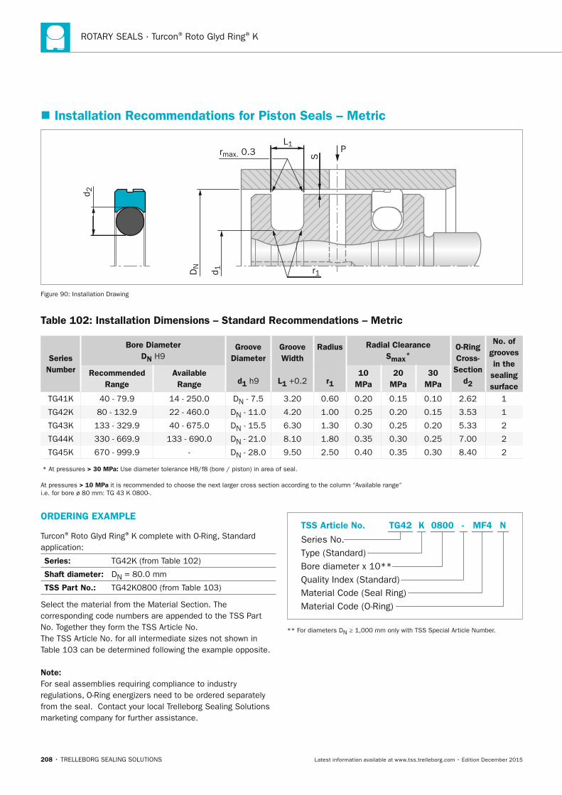
ROTARY SEALS · Turcon® Roto Glyd Ring® K
208 • TRELLEBORG SEALING SOLUTIONS Latest information available at www.tss.trelleborg.com • Edition December 2015
� Installation Recommendations for Piston Seals – Metric
P
r1
S
L1rmax. 0.3
d 2
DN
d 1
Figure 90: Installation Drawing
Table 102: Installation Dimensions – Standard Recommendations – Metric
Series number
Bore DiameterDn H9
Groove Diameter
d1 h9
Groove Width
L1 +0.2
Radius
r1
Radial ClearanceSmax*
O-Ring Cross-
Section d2
no. of grooves in the
sealing surface
Recommended Range
Available Range
10 MPa
20 MPa
30 MPa
TG41K 40 - 79.9 14 - 250.0 DN - 7.5 3.20 0.60 0.20 0.15 0.10 2.62 1
TG42K 80 - 132.9 22 - 460.0 DN - 11.0 4.20 1.00 0.25 0.20 0.15 3.53 1
TG43K 133 - 329.9 40 - 675.0 DN - 15.5 6.30 1.30 0.30 0.25 0.20 5.33 2
TG44K 330 - 669.9 133 - 690.0 DN - 21.0 8.10 1.80 0.35 0.30 0.25 7.00 2
TG45K 670 - 999.9 - DN - 28.0 9.50 2.50 0.40 0.35 0.30 8.40 2
* At pressures > 30 MPa: Use diameter tolerance H8/f8 (bore / piston) in area of seal.
At pressures > 10 MPa it is recommended to choose the next larger cross section according to the column “Available range“ i.e. for bore ø 80 mm: TG 43 K 0800-.
ORDERInG ExAMPLE
Turcon® Roto Glyd Ring® K complete with O-Ring, Standard application:
Series: TG42K (from Table 102)
Shaft diameter: DN = 80.0 mm
TSS Part no.: TG42K0800 (from Table 103)
Select the material from the Material Section. The corresponding code numbers are appended to the TSS Part No. Together they form the TSS Article No.The TSS Article No. for all intermediate sizes not shown in Table 103 can be determined following the example opposite.
note: For seal assemblies requiring compliance to industry regulations, O-Ring energizers need to be ordered separately from the seal. Contact your local Trelleborg Sealing Solutions marketing company for further assistance.
Material Code (Seal Ring)
Series No.
TSS Article No.
Material Code (O-Ring)
Bore diameter x 10**Quality Index (Standard)
Type (Standard)
MF4 NTG42 -K 0800
** For diameters DN ≥ 1,000 mm only with TSS Special Article Number.
FBP_neues_Layout_2015.indb 208 17.10.2016 13:37:15
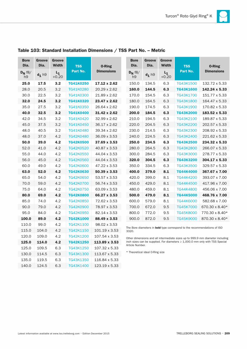
Turcon® Roto Glyd Ring® K
TRELLEBORG SEALING SOLUTIONS • 209Latest information available at www.tss.trelleborg.com • Edition December 2015
Bore Dia.
Groove Dia.
Groove Width TSS
Part no.O-Ring
DimensionsDn f8/h9
d1 h9L1
+0.20
25.0 17.5 3.2 TG41K0250 17.12 x 2.62
28.0 20.5 3.2 TG41K0280 20.29 x 2.62
30.0 22.5 3.2 TG41K0300 21.89 x 2.62
32.0 24.5 3.2 TG41K0320 23.47 x 2.62
35.0 27.5 3.2 TG41K0350 26.64 x 2.62
40.0 32.5 3.2 TG41K0400 31.42 x 2.62
42.0 34.5 3.2 TG41K0420 32.99 x 2.62
45.0 37.5 3.2 TG41K0450 36.17 x 2.62
48.0 40.5 3.2 TG41K0480 39.34 x 2.62
48.0 37.0 4.2 TG42K0480 36.09 x 3.53
50.0 39.0 4.2 TG42K0500 37.69 x 3.53
52.0 41.0 4.2 TG42K0520 40.87 x 3.53
55.0 44.0 4.2 TG42K0550 44.04 x 3.53
56.0 45.0 4.2 TG42K0560 44.04 x 3.53
60.0 49.0 4.2 TG42K0600 47.22 x 3.53
63.0 52.0 4.2 TG42K0630 50.39 x 3.53
65.0 54.0 4.2 TG42K0650 53.57 x 3.53
70.0 59.0 4.2 TG42K0700 56.74 x 3.53
75.0 64.0 4.2 TG42K0750 63.09 x 3.53
80.0 69.0 4.2 TG42K0800 66.27 x 3.53
85.0 74.0 4.2 TG42K0850 72.62 x 3.53
90.0 79.0 4.2 TG42K0900 78.97 x 3.53
95.0 84.0 4.2 TG42K0950 82.14 x 3.53
100.0 89.0 4.2 TG42K1000 88.49 x 3.53
110.0 99.0 4.2 TG42K1100 98.02 x 3.53
115.0 104.0 4.2 TG42K1150 101.19 x 3.53
120.0 109.0 4.2 TG42K1200 107.54 x 3.53
125.0 114.0 4.2 TG42K1250 113.89 x 3.53
125.0 109.5 6.3 TG43K1250 107.32 x 5.33
130.0 114.5 6.3 TG43K1300 113.67 x 5.33
135.0 119.5 6.3 TG43K1350 116.84 x 5.33
140.0 124.5 6.3 TG43K1400 123.19 x 5.33
Bore Dia.
Groove Dia.
Groove Width TSS
Part no.O-Ring
DimensionsDn f8/h9
d1 h9L1
+0.20
150.0 134.5 6.3 TG43K1500 132.72 x 5.33
160.0 144.5 6.3 TG43K1600 142.24 x 5.33
170.0 154.5 6.3 TG43K1700 151.77 x 5.33
180.0 164.5 6.3 TG43K1800 164.47 x 5.33
190.0 174.5 6.3 TG43K1900 170.82 x 5.33
200.0 184.5 6.3 TG43K2000 183.52 x 5.33
210.0 194.5 6.3 TG43K2100 189.87 x 5.33
220.0 204.5 6.3 TG43K2200 202.57 x 5.33
230.0 214.5 6.3 TG43K2300 208.92 x 5.33
240.0 224.5 6.3 TG43K2400 221.62 x 5.33
250.0 234.5 6.3 TG43K2500 234.32 x 5.33
280.0 264.5 6.3 TG43K2800 266.07 x 5.33
300.0 284.5 6.3 TG43K3000 278.77 x 5.33
320.0 304.5 6.3 TG43K3200 304.17 x 5.33
350.0 334.5 6.3 TG43K3500 329.57 x 5.33
400.0 379.0 8.1 TG44K4000 367.67 x 7.00
420.0 399.0 8.1 TG44K4200 393.07 x 7.00
450.0 429.0 8.1 TG44K4500 417.96 x 7.00
480.0 459.0 8.1 TG44K4800 456.06 x 7.00
500.0 479.0 8.1 TG44K5000 468.76 x 7.00
600.0 579.0 8.1 TG44K6000 582.68 x 7.00
700.0 672.0 9.5 TG45K7000 670.30 x 8.40*
800.0 772.0 9.5 TG45K8000 770.30 x 8.40*
900.0 872.0 9.5 TG45K9000 870.30 x 8.40*
The Bore diameters in bold type correspond to the recommendations of ISO 3320.
Other dimensions and all intermediate sizes up to 999.9 mm diameter including inch sizes can be supplied. For diameters ≥ 1,000.0 mm only with TSS Special Article Number.
* Theoretical ideal O-Ring size
Table 103: Standard Installation Dimensions / TSS Part no. – Metric
FBP_neues_Layout_2015.indb 209 17.10.2016 13:37:15

ROTARY SEALS · Turcon® Roto Glyd Ring® K
210 • TRELLEBORG SEALING SOLUTIONS Latest information available at www.tss.trelleborg.com • Edition December 2015
FBP_neues_Layout_2015.indb 210 17.10.2016 13:37:15
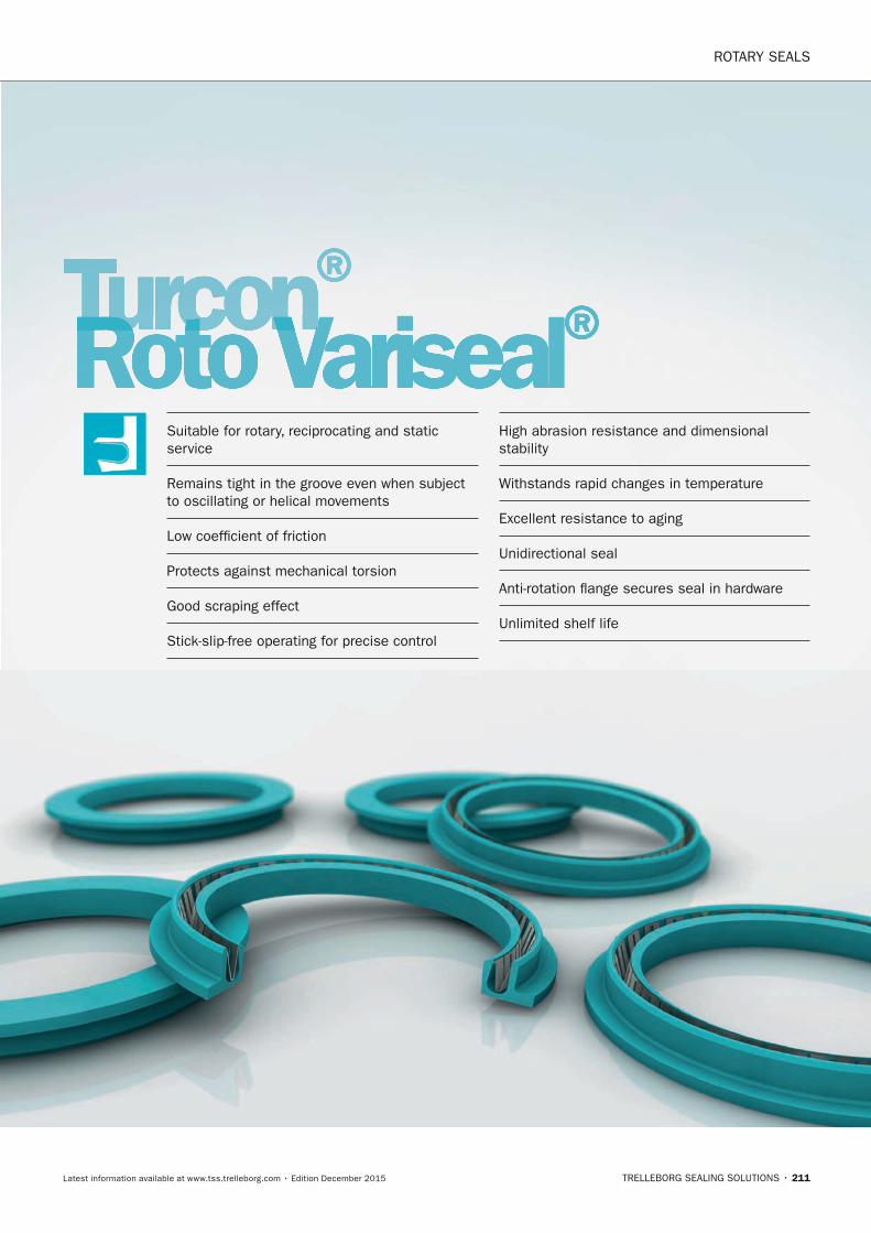
ROTARY SEALS
TRELLEBORG SEALING SOLUTIONS • 211Latest information available at www.tss.trelleborg.com • Edition December 2015
Turcon®Turcon®TurconRoto VarisealTurconRoto VarisealTurcon ®Suitable for rotary, reciprocating and static service
Remains tight in the groove even when subject to oscillating or helical movements
Low coefficient of friction
Protects against mechanical torsion
Good scraping effect
Stick-slip-free operating for precise control
High abrasion resistance and dimensional stability
Withstands rapid changes in temperature
Excellent resistance to aging
Unidirectional seal
Anti-rotation flange secures seal in hardware
Unlimited shelf life
FBP_neues_Layout_2015.indb 211 17.10.2016 13:37:17

ROTARY SEALS · Turcon® Roto Variseal®
212 • TRELLEBORG SEALING SOLUTIONS Latest information available at www.tss.trelleborg.com • Edition December 2015
FBP_neues_Layout_2015.indb 212 17.10.2016 13:37:17
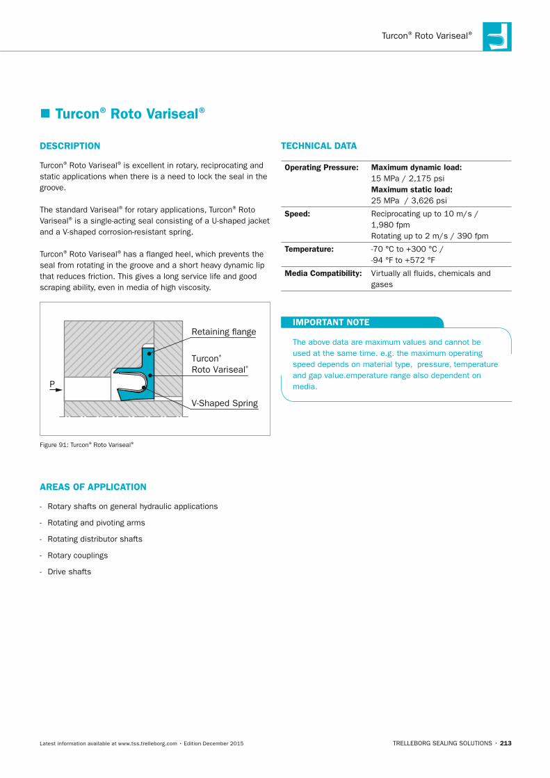
Turcon® Roto Variseal®
TRELLEBORG SEALING SOLUTIONS • 213Latest information available at www.tss.trelleborg.com • Edition December 2015
� Turcon® Roto Variseal®
DESCRIPTIOn
Turcon® Roto Variseal® is excellent in rotary, reciprocating and static applications when there is a need to lock the seal in the groove.
The standard Variseal® for rotary applications, Turcon® Roto Variseal® is a single-acting seal consisting of a U-shaped jacket and a V-shaped corrosion-resistant spring.
Turcon® Roto Variseal® has a flanged heel, which prevents the seal from rotating in the groove and a short heavy dynamic lip that reduces friction. This gives a long service life and good scraping ability, even in media of high viscosity.
Turcon® Roto Variseal®
V-Shaped Spring
Retaining ange
P
Figure 91: Turcon® Roto Variseal®
AREAS OF APPLICATIOn
- Rotary shafts on general hydraulic applications
- Rotating and pivoting arms
- Rotating distributor shafts
- Rotary couplings
- Drive shafts
TECHnICAL DATA
Operating Pressure: Maximum dynamic load: 15 MPa / 2,175 psi Maximum static load: 25 MPa / 3,626 psi
Speed: Reciprocating up to 10 m/s / 1,980 fpm Rotating up to 2 m/s / 390 fpm
Temperature: -70 °C to +300 °C / -94 °F to +572 °F
Media Compatibility: Virtually all fluids, chemicals and gases
IMPORTAnT nOTE
The above data are maximum values and cannot be used at the same time. e.g. the maximum operating speed depends on material type, pressure, temperature and gap value.emperature range also dependent on media.
FBP_neues_Layout_2015.indb 213 17.10.2016 13:37:18
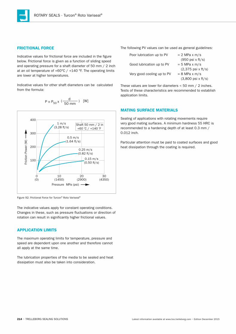
ROTARY SEALS · Turcon® Roto Variseal®
214 • TRELLEBORG SEALING SOLUTIONS Latest information available at www.tss.trelleborg.com • Edition December 2015
FRICTIOnAL FORCE
Indicative values for frictional force are included in the figure below. Frictional force is given as a function of sliding speed and operating pressure for a shaft diameter of 50 mm / 2 inch at an oil temperature of +60°C / +140 °F. The operating limits are lower at higher temperatures.
Indicative values for other shaft diameters can be calculated from the formula:
dP P50 x 50 mm
( ) [W]
(0)0 10 20 30
100
200
300
400
(1450) (2900) (4350)
1 m/s(3.28 ft/s)
0.5 m/s(1.64 ft/s)
0.25 m/s(0.82 ft/s)
0.15 m/s(0.50 ft/s)
Shaft 50 mm / 2 in+60 ºC / +140 ºF
Pressure MPa (psi)
Fric
tion
Pow
er (W
)
Figure 92: Frictional Force for Turcon® Roto Variseal®
The indicative values apply for constant operating conditions. Changes in these, such as pressure fluctuations or direction of rotation can result in significantly higher frictional values.
APPLICATIOn LIMITS
The maximum operating limits for temperature, pressure and speed are dependent upon one another and therefore cannot all apply at the same time.
The lubrication properties of the media to be sealed and heat dissipation must also be taken into consideration.
The following PV values can be used as general guidelines:
Poor lubrication up to PV = 2 MPa x m/s (950 psi x ft/s)
Good lubrication up to PV = 5 MPa x m/s (2,375 psi x ft/s)
Very good cooling up to PV = 8 MPa x m/s (3,800 psi x ft/s)
These values are lower for diameters < 50 mm / 2 inches. Tests of these characteristics are recommended to establish application limits.
MATInG SURFACE MATERIALS
Sealing of applications with rotating movements require very good mating surfaces. A minimum hardness 55 HRC is recommended to a hardening depth of at least 0.3 mm / 0.012 inch.
Particular attention must be paid to coated surfaces and good heat dissipation through the coating is required.
FBP_neues_Layout_2015.indb 214 17.10.2016 13:37:18

Turcon® Roto Variseal®
TRELLEBORG SEALING SOLUTIONS • 215Latest information available at www.tss.trelleborg.com • Edition December 2015
FBP_neues_Layout_2015.indb 215 17.10.2016 13:37:18
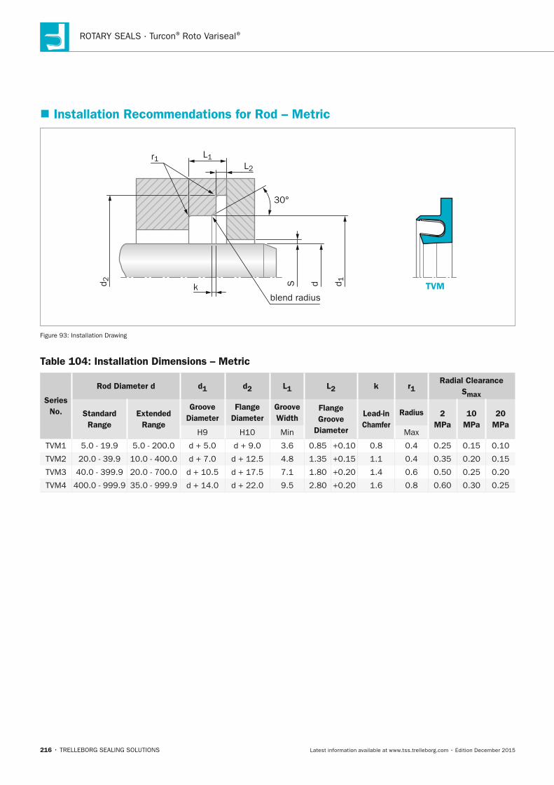
ROTARY SEALS · Turcon® Roto Variseal®
216 • TRELLEBORG SEALING SOLUTIONS Latest information available at www.tss.trelleborg.com • Edition December 2015
� Installation Recommendations for Rod – Metric
blend radius
dS d 1
30°
L1r1
TVM
L2
d 2
k
Figure 93: Installation Drawing
Table 104: Installation Dimensions – Metric
Series no.
Rod Diameter d d1 d2 L1 L2 k r1Radial Clearance
Smax
Standard Range
Extended
Range
Groove Diameter
Flange Diameter
Groove Width
Flange Groove
Diameter
Lead-in Chamfer
Radius 2 MPa
10 MPa
20 MPa
H9 H10 Min Max
TVM1 5.0 - 19.9 5.0 - 200.0 d + 5.0 d + 9.0 3.6 0.85 +0.10 0.8 0.4 0.25 0.15 0.10
TVM2 20.0 - 39.9 10.0 - 400.0 d + 7.0 d + 12.5 4.8 1.35 +0.15 1.1 0.4 0.35 0.20 0.15
TVM3 40.0 - 399.9 20.0 - 700.0 d + 10.5 d + 17.5 7.1 1.80 +0.20 1.4 0.6 0.50 0.25 0.20
TVM4 400.0 - 999.9 35.0 - 999.9 d + 14.0 d + 22.0 9.5 2.80 +0.20 1.6 0.8 0.60 0.30 0.25
FBP_neues_Layout_2015.indb 216 17.10.2016 13:37:19
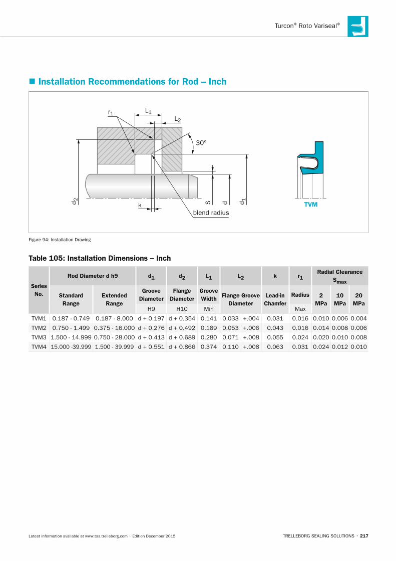
Turcon® Roto Variseal®
TRELLEBORG SEALING SOLUTIONS • 217Latest information available at www.tss.trelleborg.com • Edition December 2015
� Installation Recommendations for Rod – Inch
blend radius
dS d 1
30°
L1r1
TVM
L2
d 2
k
Figure 94: Installation Drawing
Table 105: Installation Dimensions – Inch
Series no.
Rod Diameter d h9 d1 d2 L1 L2 k r1Radial Clearance
Smax
Standard Range
Extended Range
Groove Diameter
Flange Diameter
Groove Width Flange Groove
DiameterLead-in Chamfer
Radius 2 MPa
10 MPa
20 MPa
H9 H10 Min Max
TVM1 0.187 - 0.749 0.187 - 8.000 d + 0.197 d + 0.354 0.141 0.033 +.004 0.031 0.016 0.010 0.006 0.004
TVM2 0.750 - 1.499 0.375 - 16.000 d + 0.276 d + 0.492 0.189 0.053 +.006 0.043 0.016 0.014 0.008 0.006
TVM3 1.500 - 14.999 0.750 - 28.000 d + 0.413 d + 0.689 0.280 0.071 +.008 0.055 0.024 0.020 0.010 0.008
TVM4 15.000 -39.999 1.500 - 39.999 d + 0.551 d + 0.866 0.374 0.110 +.008 0.063 0.031 0.024 0.012 0.010
FBP_neues_Layout_2015.indb 217 17.10.2016 13:37:19
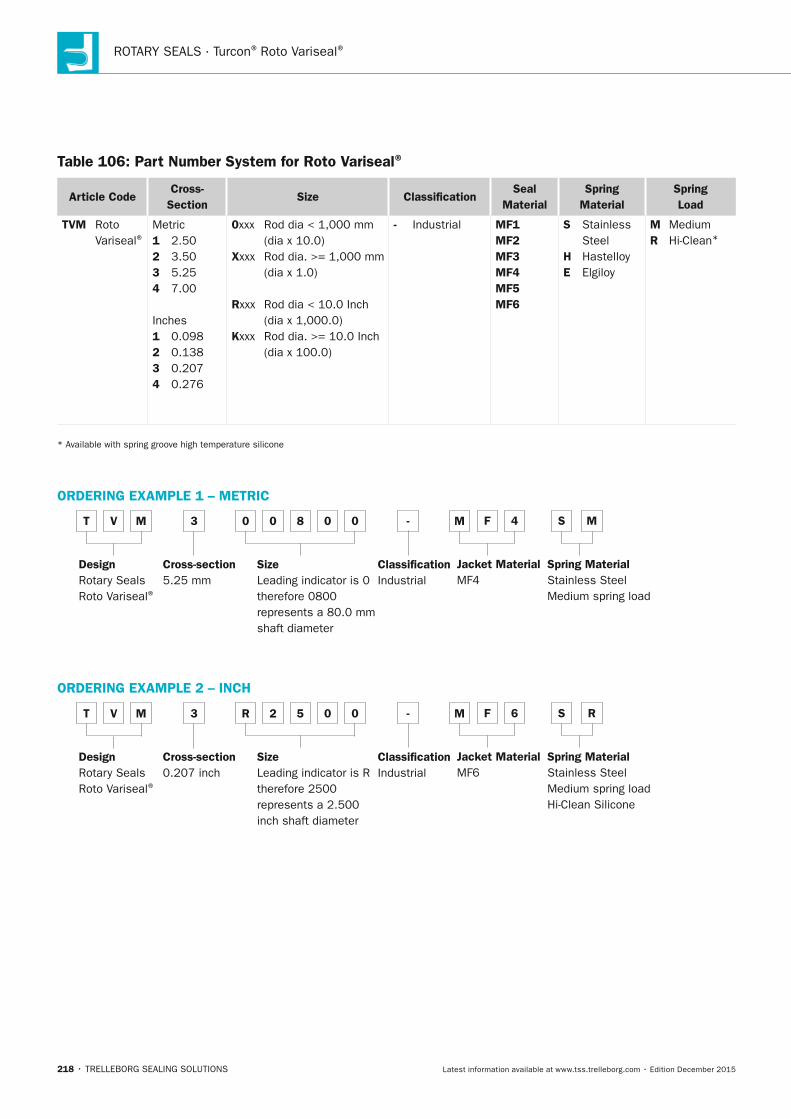
ROTARY SEALS · Turcon® Roto Variseal®
218 • TRELLEBORG SEALING SOLUTIONS Latest information available at www.tss.trelleborg.com • Edition December 2015
Table 106: Part number System for Roto Variseal®
Article CodeCross-
SectionSize Classification
Seal Material
Spring Material
Spring Load
TVM Roto Variseal®
Metric1 2.502 3.503 5.254 7.00
Inches1 0.0982 0.1383 0.2074 0.276
0xxx Rod dia < 1,000 mm (dia x 10.0)xxxx Rod dia. >= 1,000 mm (dia x 1.0)
Rxxx Rod dia < 10.0 Inch (dia x 1,000.0)Kxxx Rod dia. >= 10.0 Inch (dia x 100.0)
- Industrial MF1 MF2 MF3 MF4 MF5 MF6
S Stainless Steel H Hastelloy E Elgiloy
M Medium R Hi-Clean*
* Available with spring groove high temperature silicone
ORDERInG ExAMPLE 1 – METRIC
T V M 3 0 0 8 0 0 S M
Spring MaterialStainless Steel Medium spring load
Jacket MaterialMF4
SizeLeading indicator is 0 therefore 0800 represents a 80.0 mm shaft diameter
Cross-section5.25 mm
DesignRotary SealsRoto Variseal®
ClassificationIndustrial
F 4M-
ORDERInG ExAMPLE 2 – InCH
T V M 3 R 2 5 0 0 S R
Spring MaterialStainless Steel Medium spring loadHi-Clean Silicone
Jacket MaterialMF6
SizeLeading indicator is R therefore 2500 represents a 2.500 inch shaft diameter
Cross-section0.207 inch
DesignRotary SealsRoto Variseal®
ClassificationIndustrial
F 6M-
FBP_neues_Layout_2015.indb 218 17.10.2016 13:37:20
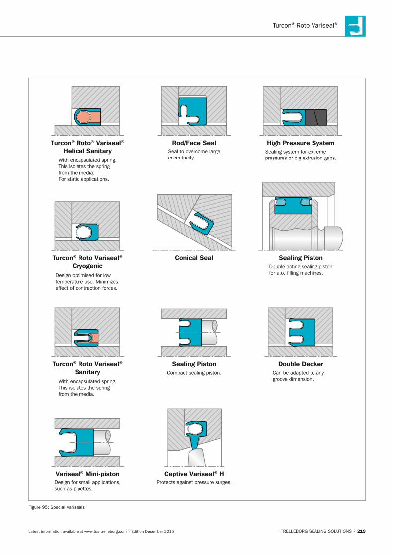
Turcon® Roto Variseal®
TRELLEBORG SEALING SOLUTIONS • 219Latest information available at www.tss.trelleborg.com • Edition December 2015
Rod/Face Seal
Sealing Piston
Double Decker
Conical Seal
Seal to overcome largeeccentricity.
Double acting sealing pistonfor a.o. filling machines.
Can be adapted to anygroove dimension.With encapsulated spring.
This isolates the springfrom the media.
Turcon® Roto Variseal®
CryogenicDesign optimised for lowtemperature use. Minimizes effect of contraction forces.
Turcon® Roto® Variseal®
Helical Sanitary
Turcon® Roto Variseal®
Sanitary
With encapsulated spring.This isolates the springfrom the media.For static applications.
High Pressure SystemSealing system for extremepressures or big extrusion gaps.
Variseal® Mini-pistonDesign for small applications,such as pipettes.
Captive Variseal® HProtects against pressure surges.
Sealing PistonCompact sealing piston.
Figure 95: Special Variseals
FBP_neues_Layout_2015.indb 219 17.10.2016 13:37:20

ROTARY SEALS · Turcon® Roto Variseal®
220 • TRELLEBORG SEALING SOLUTIONS Latest information available at www.tss.trelleborg.com • Edition December 2015
FBP_neues_Layout_2015.indb 220 17.10.2016 13:37:21
ROTARY SEALS
TRELLEBORG SEALING SOLUTIONS • 221Latest information available at www.tss.trelleborg.com • Edition December 2015
Turcon®Turcon®TurconRoto VL SealTurconRoto VL SealTurcon ®Single-acting seal for rotary, turning and oscillating movements
Lubricant reservoir
Very low friction
Stick-slip-free operation
Simple one piece housing design
Available for shaft and bore application
No vulcanization to mating surface
Installed in standard O-Ring housing
FBP_neues_Layout_2015.indb 221 17.10.2016 13:37:23

ROTARY SEALS · Turcon® Roto VL Seal®
222 • TRELLEBORG SEALING SOLUTIONS Latest information available at www.tss.trelleborg.com • Edition December 2015
FBP_neues_Layout_2015.indb 222 17.10.2016 13:37:23
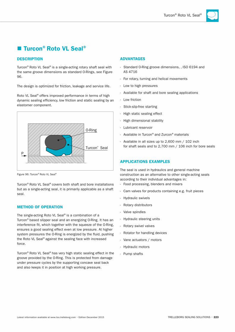
Turcon® Roto VL Seal®
TRELLEBORG SEALING SOLUTIONS • 223Latest information available at www.tss.trelleborg.com • Edition December 2015
� Turcon®Roto VL Seal®
DESCRIPTIOn
Turcon®Roto VL Seal®is a single-acting rotary shaft seal with the same groove dimensions as standard O-Rings, see Figure 96.
The design is optimized for friction, leakage and service life.
Roto VL Seal®offers improved performance in terms of high dynamic sealing efficiency, low friction and static sealing by an elastomer component.
PTurcon® Seal
O-Ring
Figure 96: Turcon®Roto VL Seal®
Turcon®Roto VL Seal®covers both shaft and bore installations but as a single-acting seal, it is primarily applicable as a shaft seal.
METHOD OF OPERATIOn
The single-acting Roto VL Seal®is a combination of a Turcon®based slipper seal and an energizing O-Ring. It has an interference fit, which together with the squeeze of the O-Ring, ensures a good sealing effect even at low pressure. At higher system pressures the O-Ring is energized by the fluid, pushing the Roto VL Seal®against the sealing face with increased force.
Turcon®Roto VL Seal®has very high static sealing effect in the groove provided by the O-Ring. This is protected from damage under pressure cycles by the supporting concave seal back and also keeps it in position at high working pressure.
ADVAnTAGES
- Standard O-Ring groove dimensions, , ISO 6194 and AS 4716
- For rotary, turning and helical movements
- Low to high pressures
- Available for shaft and bore sealing applications
- Low friction
- Stick-slip-free starting
- High static sealing effect
- High dimensional stability
- Lubricant reservoir
- Available in Turcon®and Zurcon®materials
- Available in all sizes up to 2,600 mm / 102 inch for shaft seals and to 2,700 mm / 106 inch for bore seals
APPLICATIOnS ExAMPLES
The seal is used in hydraulics and general machine construction as an alternative to other single-acting seals according to their individual advantages in: - Food processing, blenders and mixers
- Cam valves for products containing e.g. fruit pieces
- Hydraulic swivels
- Rotary distributors
- Valve spindles
- Hydraulic steering units
- Rotary swivel valves
- Rotator for handling devices
- Vane actuators / motors
- Hydraulic motors
- Pump shafts
FBP_neues_Layout_2015.indb 223 17.10.2016 13:37:23
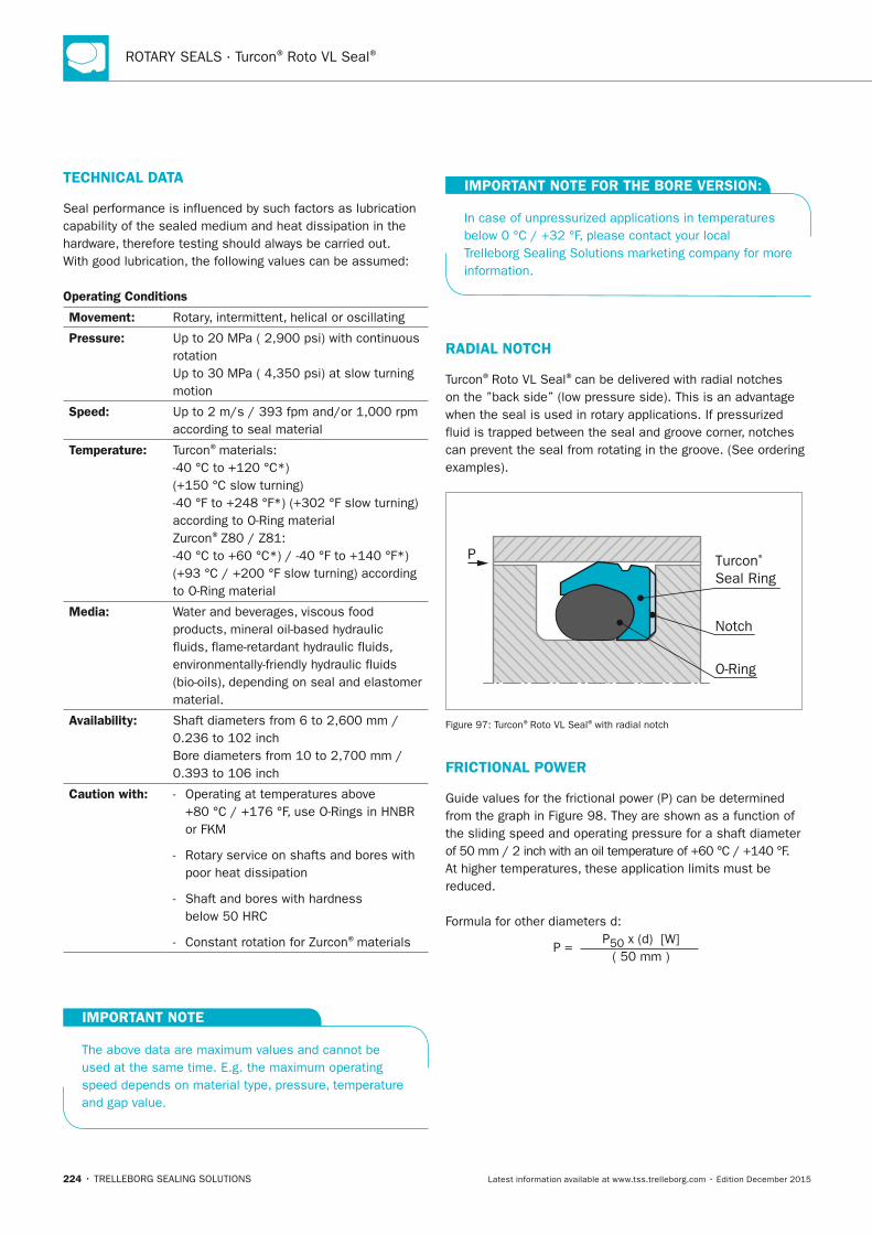
ROTARY SEALS · Turcon® Roto VL Seal®
224 • TRELLEBORG SEALING SOLUTIONS Latest information available at www.tss.trelleborg.com • Edition December 2015
TECHnICAL DATA
Seal performance is influenced by such factors as lubrication capability of the sealed medium and heat dissipation in the hardware, therefore testing should always be carried out.With good lubrication, the following values can be assumed:
Operating Conditions
Movement: Rotary, intermittent, helical or oscillating
Pressure: Up to 20 MPa ( 2,900 psi) with continuous rotation Up to 30 MPa ( 4,350 psi) at slow turning motion
Speed: Up to 2 m/s / 393 fpm and/or 1,000 rpm according to seal material
Temperature: Turcon®materials: -40 °C to +120 °C*) (+150 °C slow turning) -40 °F to +248 °F*) (+302 °F slow turning) according to O-Ring materialZurcon®Z80 / Z81: -40 °C to +60 °C*) / -40 °F to +140 °F*) (+93 °C / +200 °F slow turning) according to O-Ring material
Media: Water and beverages, viscous food products, mineral oil-based hydraulic fluids, flame-retardant hydraulic fluids, environmentally-friendly hydraulic fluids (bio-oils), depending on seal and elastomer material.
Availability: Shaft diameters from 6 to 2,600 mm / 0.236 to 102 inchBore diameters from 10 to 2,700 mm / 0.393 to 106 inch
Caution with: - Operating at temperatures above +80 °C / +176 °F, use O-Rings in HNBR or FKM
- Rotary service on shafts and bores with poor heat dissipation
- Shaft and bores with hardness below 50 HRC
- Constant rotation for Zurcon®materials
IMPORTAnT nOTE
The above data are maximum values and cannot be used at the same time. E.g. the maximum operating speed depends on material type, pressure, temperature and gap value.
IMPORTAnT nOTE FOR THE BORE VERSIOn:
In case of unpressurized applications in temperatures below 0 °C / +32 °F, please contact your local Trelleborg Sealing Solutions marketing company for more information.
RADIAL nOTCH
Turcon®Roto VL Seal®can be delivered with radial notches on the ”back side” (low pressure side). This is an advantage when the seal is used in rotary applications. If pressurized fluid is trapped between the seal and groove corner, notches can prevent the seal from rotating in the groove. (See ordering examples).
P Turcon® Seal Ring
Notch
O-Ring
Figure 97: Turcon®Roto VL Seal®with radial notch
FRICTIOnAL POWER
Guide values for the frictional power (P) can be determined from the graph in Figure 98. They are shown as a function of the sliding speed and operating pressure for a shaft diameter of 50 mm / 2 inch with an oil temperature of +60 °C / +140 °F. At higher temperatures, these application limits must be reduced.
Formula for other diameters d:
P = P50 x (d) [W]
( 50 mm )
FBP_neues_Layout_2015.indb 224 17.10.2016 13:37:24
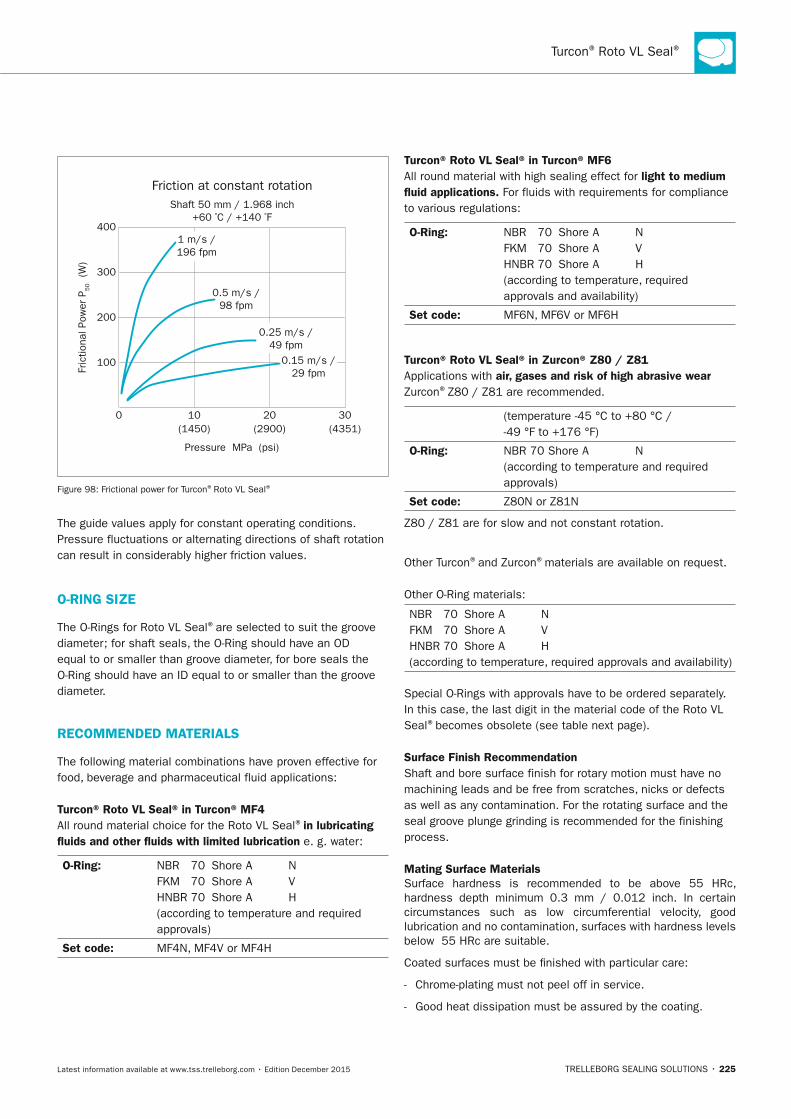
Turcon® Roto VL Seal®
TRELLEBORG SEALING SOLUTIONS • 225Latest information available at www.tss.trelleborg.com • Edition December 2015
Fric
tiona
l Pow
er P
50
(W)
Friction at constant rotation
0
100
200
300
400
10(1450) (2900) (4351)
Pressure MPa (psi)
20 30
1 m/s /196 fpm
0.5 m/s /98 fpm
0.25 m/s /49 fpm
0.15 m/s /29 fpm
Shaft 50 mm / 1.968 inch+60 ºC / +140 ºF
Figure 98: Frictional power for Turcon®Roto VL Seal®
The guide values apply for constant operating conditions. Pressure fluctuations or alternating directions of shaft rotation can result in considerably higher friction values.
O-RInG SIZE
The O-Rings for Roto VL Seal®are selected to suit the groove diameter; for shaft seals, the O-Ring should have an OD equal to or smaller than groove diameter, for bore seals the O-Ring should have an ID equal to or smaller than the groove diameter.
RECOMMEnDED MATERIALS
The following material combinations have proven effective for food, beverage and pharmaceutical fluid applications:
Turcon® Roto VL Seal® in Turcon® MF4 All round material choice for the Roto VL Seal®in lubricating fluids and other fluids with limited lubrication e. g. water:
O-Ring: NBR 70 Shore A N FKM 70 Shore A V HNBR 70 Shore A H (according to temperature and required approvals)
Set code: MF4N, MF4V or MF4H
Turcon® Roto VL Seal® in Turcon® MF6 All round material with high sealing effect for light to medium fluid applications. For fluids with requirements for compliance to various regulations:
O-Ring: NBR 70 Shore A N FKM 70 Shore A V HNBR 70 Shore A H (according to temperature, required approvals and availability)
Set code: MF6N, MF6V or MF6H
Turcon® Roto VL Seal® in Zurcon® Z80 / Z81 Applications with air, gases and risk of high abrasive wear Zurcon®Z80 / Z81 are recommended.
(temperature -45 °C to +80 °C / -49 °F to +176 °F)
O-Ring: NBR 70 Shore A N (according to temperature and required approvals)
Set code: Z80N or Z81N
Z80 / Z81 are for slow and not constant rotation.
Other Turcon®and Zurcon®materials are available on request.
Other O-Ring materials:
NBR 70 Shore A N FKM 70 Shore A V HNBR 70 Shore A H (according to temperature, required approvals and availability)
Special O-Rings with approvals have to be ordered separately. In this case, the last digit in the material code of the Roto VL Seal®becomes obsolete (see table next page).
Surface Finish Recommendation Shaft and bore surface finish for rotary motion must have no machining leads and be free from scratches, nicks or defects as well as any contamination. For the rotating surface and the seal groove plunge grinding is recommended for the finishing process.
Mating Surface MaterialsSurface hardness is recommended to be above 55 HRc, hardness depth minimum 0.3 mm / 0.012 inch. In certain circumstances such as low circumferential velocity, good lubrication and no contamination, surfaces with hardness levels below 55 HRc are suitable.
Coated surfaces must be finished with particular care:
- Chrome-plating must not peel off in service.
- Good heat dissipation must be assured by the coating.
FBP_neues_Layout_2015.indb 225 17.10.2016 13:37:24
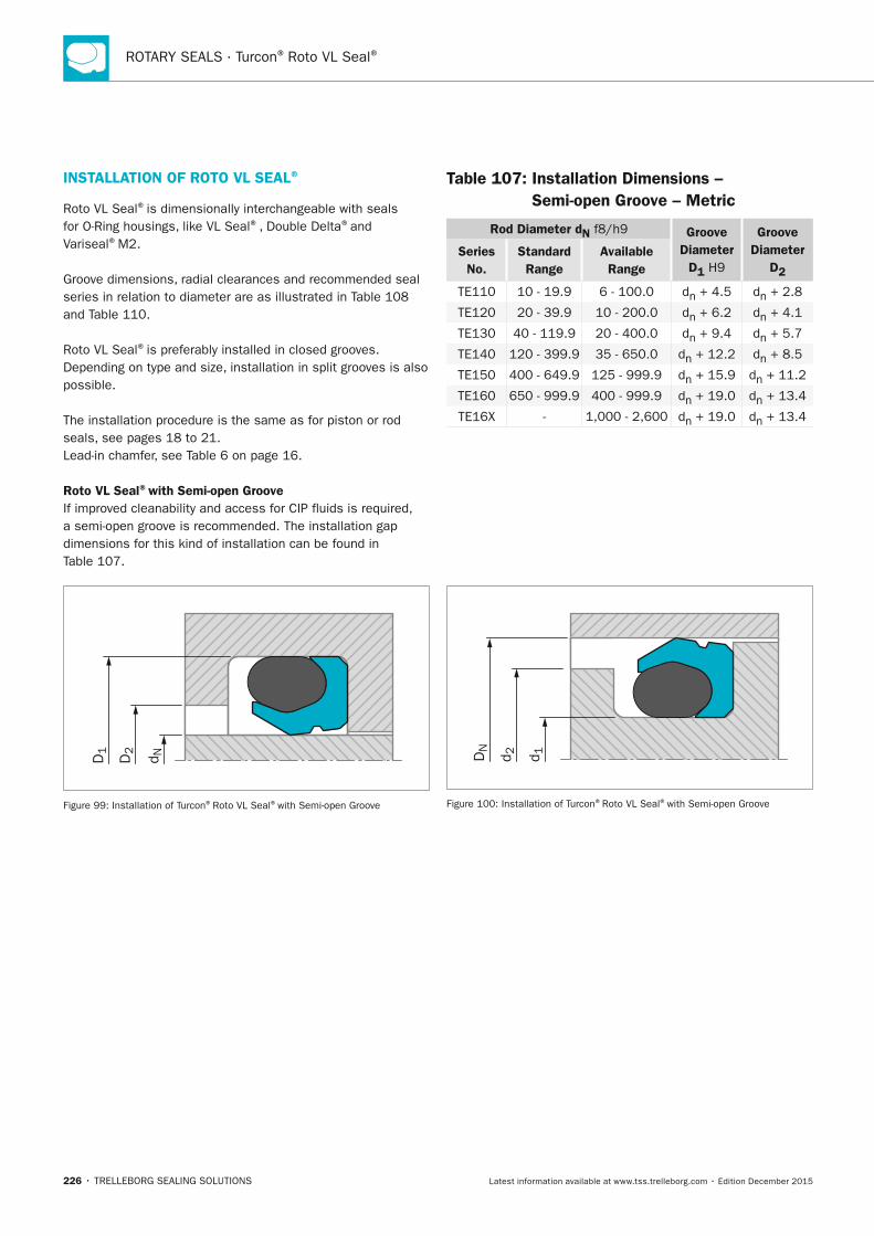
ROTARY SEALS · Turcon® Roto VL Seal®
226 • TRELLEBORG SEALING SOLUTIONS Latest information available at www.tss.trelleborg.com • Edition December 2015
InSTALLATIOn OF ROTO VL SEAL®
Roto VL Seal®is dimensionally interchangeable with seals for O-Ring housings, like VL Seal®, Double Delta®and Variseal®M2.
Groove dimensions, radial clearances and recommended seal series in relation to diameter are as illustrated in Table 108 and Table 110.
Roto VL Seal®is preferably installed in closed grooves. Depending on type and size, installation in split grooves is also possible.
The installation procedure is the same as for piston or rod seals, see pages 18 to 21.Lead-in chamfer, see Table 6 on page 16.
Roto VL Seal®with Semi-open GrooveIf improved cleanability and access for CIP fluids is required, a semi-open groove is recommended. The installation gap dimensions for this kind of installation can be found in Table 107.
D1
D2
d N
Figure 99: Installation of Turcon®Roto VL Seal®with Semi-open Groove
Table 107: Installation Dimensions – Semi-open Groove – Metric
Rod Diameter dn f8/h9 Groove Diameter
D1 H9
Groove Diameter
D2
Series no.
Standard Range
Available Range
TE110 10 - 19.9 6 - 100.0 dn + 4.5 dn + 2.8
TE120 20 - 39.9 10 - 200.0 dn + 6.2 dn + 4.1
TE130 40 - 119.9 20 - 400.0 dn + 9.4 dn + 5.7
TE140 120 - 399.9 35 - 650.0 dn + 12.2 dn + 8.5
TE150 400 - 649.9 125 - 999.9 dn + 15.9 dn + 11.2
TE160 650 - 999.9 400 - 999.9 dn + 19.0 dn + 13.4
TE16X - 1,000 - 2,600 dn + 19.0 dn + 13.4
DN
d 2 d 1
Figure 100: Installation of Turcon®Roto VL Seal®with Semi-open Groove
FBP_neues_Layout_2015.indb 226 17.10.2016 13:37:25

Turcon® Roto VL Seal®
TRELLEBORG SEALING SOLUTIONS • 227Latest information available at www.tss.trelleborg.com • Edition December 2015
FBP_neues_Layout_2015.indb 227 17.10.2016 13:37:25
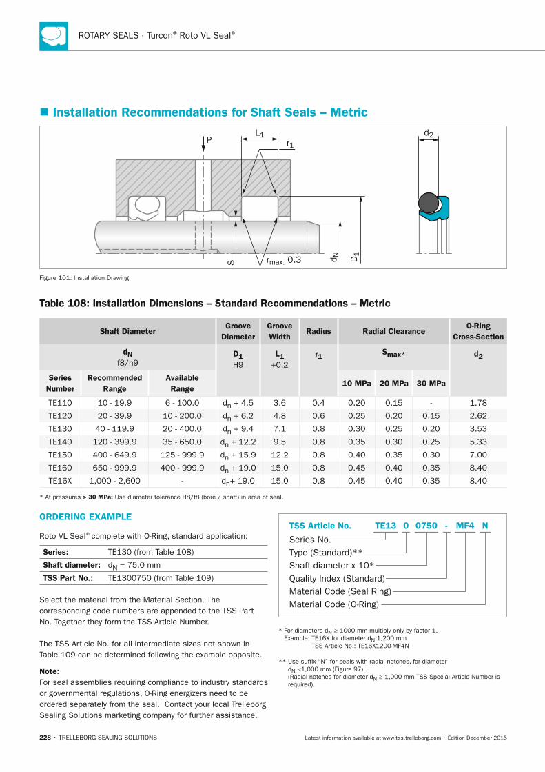
ROTARY SEALS · Turcon® Roto VL Seal®
228 • TRELLEBORG SEALING SOLUTIONS Latest information available at www.tss.trelleborg.com • Edition December 2015
� Installation Recommendations for Shaft Seals – Metric
PL1
S rmax. 0.3
d2r1
D1
d N
Figure 101: Installation Drawing
Table 108: Installation Dimensions – Standard Recommendations – Metric
Shaft DiameterGroove
DiameterGroove Width
Radius Radial ClearanceO-Ring
Cross-Section
dn f8/h9
D1 H9
L1 +0.2
r1 Smax* d2
Series number
Recommended Range
Available Range
10 MPa 20 MPa 30 MPa
TE110 10 - 19.9 6 - 100.0 dn + 4.5 3.6 0.4 0.20 0.15 - 1.78
TE120 20 - 39.9 10 - 200.0 dn + 6.2 4.8 0.6 0.25 0.20 0.15 2.62
TE130 40 - 119.9 20 - 400.0 dn + 9.4 7.1 0.8 0.30 0.25 0.20 3.53
TE140 120 - 399.9 35 - 650.0 dn + 12.2 9.5 0.8 0.35 0.30 0.25 5.33
TE150 400 - 649.9 125 - 999.9 dn + 15.9 12.2 0.8 0.40 0.35 0.30 7.00
TE160 650 - 999.9 400 - 999.9 dn + 19.0 15.0 0.8 0.45 0.40 0.35 8.40
TE16X 1,000 - 2,600 - dn+ 19.0 15.0 0.8 0.45 0.40 0.35 8.40
* At pressures > 30 MPa: Use diameter tolerance H8/f8 (bore / shaft) in area of seal.
ORDERInG ExAMPLE
Roto VL Seal®complete with O-Ring, standard application:
Series: TE130 (from Table 108)
Shaft diameter: dN = 75.0 mm
TSS Part no.: TE1300750 (from Table 109)
Select the material from the Material Section. The corresponding code numbers are appended to the TSS Part No. Together they form the TSS Article Number.
The TSS Article No. for all intermediate sizes not shown in Table 109 can be determined following the example opposite.
note: For seal assemblies requiring compliance to industry standards or governmental regulations, O-Ring energizers need to be ordered separately from the seal. Contact your local Trelleborg Sealing Solutions marketing company for further assistance.
Material Code (Seal Ring)
Series No.
TSS Article No.
Material Code (O-Ring)
Shaft diameter x 10*Quality Index (Standard)
Type (Standard)**
MF4 NTE13 -0 0750
* For diameters dN ≥ 1000 mm multiply only by factor 1. Example: TE16X for diameter dN 1,200 mm
TSS Article No.: TE16X1200-MF4N
** Use suffix “N” for seals with radial notches, for diameter dN <1,000 mm (Figure 97). (Radial notches for diameter dN ≥ 1,000 mm TSS Special Article Number is required).
FBP_neues_Layout_2015.indb 228 17.10.2016 13:37:26
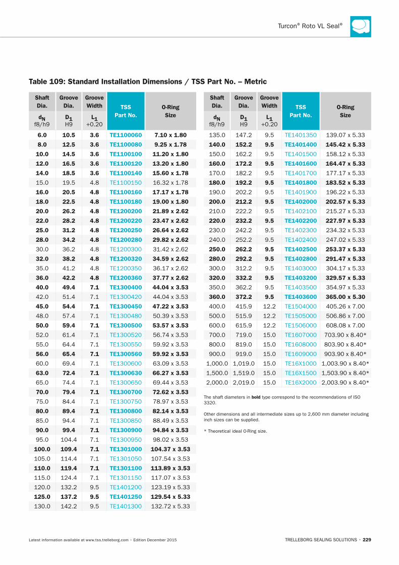
Turcon® Roto VL Seal®
TRELLEBORG SEALING SOLUTIONS • 229Latest information available at www.tss.trelleborg.com • Edition December 2015
Shaft Dia.
Groove Dia.
Groove Width TSS
Part no.O-Ring Sizedn
f8/h9D1 H9
L1 +0.20
6.0 10.5 3.6 TE1100060 7.10 x 1.80
8.0 12.5 3.6 TE1100080 9.25 x 1.78
10.0 14.5 3.6 TE1100100 11.20 x 1.80
12.0 16.5 3.6 TE1100120 13.20 x 1.80
14.0 18.5 3.6 TE1100140 15.60 x 1.78
15.0 19.5 4.8 TE1100150 16.32 x 1.78
16.0 20.5 4.8 TE1100160 17.17 x 1.78
18.0 22.5 4.8 TE1100180 19.00 x 1.80
20.0 26.2 4.8 TE1200200 21.89 x 2.62
22.0 28.2 4.8 TE1200220 23.47 x 2.62
25.0 31.2 4.8 TE1200250 26.64 x 2.62
28.0 34.2 4.8 TE1200280 29.82 x 2.62
30.0 36.2 4.8 TE1200300 31.42 x 2.62
32.0 38.2 4.8 TE1200320 34.59 x 2.62
35.0 41.2 4.8 TE1200350 36.17 x 2.62
36.0 42.2 4.8 TE1200360 37.77 x 2.62
40.0 49.4 7.1 TE1300400 44.04 x 3.53
42.0 51.4 7.1 TE1300420 44.04 x 3.53
45.0 54.4 7.1 TE1300450 47.22 x 3.53
48.0 57.4 7.1 TE1300480 50.39 x 3.53
50.0 59.4 7.1 TE1300500 53.57 x 3.53
52.0 61.4 7.1 TE1300520 56.74 x 3.53
55.0 64.4 7.1 TE1300550 59.92 x 3.53
56.0 65.4 7.1 TE1300560 59.92 x 3.53
60.0 69.4 7.1 TE1300600 63.09 x 3.53
63.0 72.4 7.1 TE1300630 66.27 x 3.53
65.0 74.4 7.1 TE1300650 69.44 x 3.53
70.0 79.4 7.1 TE1300700 72.62 x 3.53
75.0 84.4 7.1 TE1300750 78.97 x 3.53
80.0 89.4 7.1 TE1300800 82.14 x 3.53
85.0 94.4 7.1 TE1300850 88.49 x 3.53
90.0 99.4 7.1 TE1300900 94.84 x 3.53
95.0 104.4 7.1 TE1300950 98.02 x 3.53
100.0 109.4 7.1 TE1301000 104.37 x 3.53
105.0 114.4 7.1 TE1301050 107.54 x 3.53
110.0 119.4 7.1 TE1301100 113.89 x 3.53
115.0 124.4 7.1 TE1301150 117.07 x 3.53
120.0 132.2 9.5 TE1401200 123.19 x 5.33
125.0 137.2 9.5 TE1401250 129.54 x 5.33
130.0 142.2 9.5 TE1401300 132.72 x 5.33
Shaft Dia.
Groove Dia.
Groove Width TSS
Part no.O-Ring Sizedn
f8/h9D1 H9
L1 +0.20
135.0 147.2 9.5 TE1401350 139.07 x 5.33
140.0 152.2 9.5 TE1401400 145.42 x 5.33
150.0 162.2 9.5 TE1401500 158.12 x 5.33
160.0 172.2 9.5 TE1401600 164.47 x 5.33
170.0 182.2 9.5 TE1401700 177.17 x 5.33
180.0 192.2 9.5 TE1401800 183.52 x 5.33
190.0 202.2 9.5 TE1401900 196.22 x 5.33
200.0 212.2 9.5 TE1402000 202.57 x 5.33
210.0 222.2 9.5 TE1402100 215.27 x 5.33
220.0 232.2 9.5 TE1402200 227.97 x 5.33
230.0 242.2 9.5 TE1402300 234.32 x 5.33
240.0 252.2 9.5 TE1402400 247.02 x 5.33
250.0 262.2 9.5 TE1402500 253.37 x 5.33
280.0 292.2 9.5 TE1402800 291.47 x 5.33
300.0 312.2 9.5 TE1403000 304.17 x 5.33
320.0 332.2 9.5 TE1403200 329.57 x 5.33
350.0 362.2 9.5 TE1403500 354.97 x 5.33
360.0 372.2 9.5 TE1403600 365.00 x 5.30
400.0 415.9 12.2 TE1504000 405.26 x 7.00
500.0 515.9 12.2 TE1505000 506.86 x 7.00
600.0 615.9 12.2 TE1506000 608.08 x 7.00
700.0 719.0 15.0 TE1607000 703.90 x 8.40*
800.0 819.0 15.0 TE1608000 803.90 x 8.40*
900.0 919.0 15.0 TE1609000 903.90 x 8.40*
1,000.0 1,019.0 15.0 TE16X1000 1,003.90 x 8.40*
1,500.0 1,519.0 15.0 TE16X1500 1,503.90 x 8.40*
2,000.0 2,019.0 15.0 TE16X2000 2,003.90 x 8.40*
The shaft diameters in bold type correspond to the recommendations of ISO 3320.
Other dimensions and all intermediate sizes up to 2,600 mm diameter including inch sizes can be supplied.
* Theoretical ideal O-Ring size.
Table 109: Standard Installation Dimensions / TSS Part no. – Metric
FBP_neues_Layout_2015.indb 229 17.10.2016 13:37:27
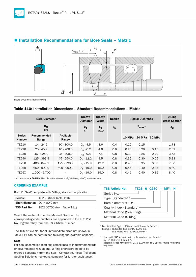
ROTARY SEALS · Turcon® Roto VL Seal®
230 • TRELLEBORG SEALING SOLUTIONS Latest information available at www.tss.trelleborg.com • Edition December 2015
� Installation Recommendations for Bore Seals – Metric
P
S
L1rmax. 0.3
r1DN
d 1
d2
Figure 102: Installation Drawing
Table 110: Installation Dimensions – Standard Recommendations – Metric
Bore DiameterGroove
DiameterGroove Width
Radius Radial ClearanceO-Ring
Cross-Section
Dn H9
d1 h9
L1 +0.2
r1 Smax* d2
Series number
Recommended Range
Available Range
10 MPa 20 MPa 30 MPa
TE210 14 - 24.9 10 - 100.0 Dn - 4.5 3.6 0.4 0.20 0.15 - 1.78
TE220 25 - 45.9 16 - 200.0 Dn - 6.2 4.8 0.6 0.25 0.20 0.15 2.62
TE230 46 - 124.9 28 - 400.0 Dn - 9.4 7.1 0.8 0.30 0.25 0.20 3.53
TE240 125 - 399.9 45 - 650.0 Dn - 12.2 9.5 0.8 0.35 0.30 0.25 5.33
TE250 400 - 649.9 125 - 999.9 Dn - 15.9 12.2 0.8 0.40 0.35 0.30 7.00
TE260 650 - 999.9 400 - 999.9 Dn - 19.0 15.0 0.8 0.45 0.40 0.35 8.40
TE26X 1,000 - 2,700 - Dn - 19.0 15.0 0.8 0.45 0.40 0.35 8.40
* At pressures > 30 MPa: Use diameter tolerance H8/f8 (bore / shaft) in area of seal.
ORDERInG ExAMPLE
Roto VL Seal®complete with O-Ring, standard application:
Series: TE230 (from Table 110)
Shaft diameter: DN = 80.0 mm
TSS Part no.: TE2300750 (from Table 111)
Select the material from the Material Section. The corresponding code numbers are appended to the TSS Part No. Together they form the TSS Article Number.
The TSS Article No. for all intermediate sizes not shown in Table 111 can be determined following the example opposite.
note: For seal assemblies requiring compliance to industry standards or governmental regulations, O-Ring energizers need to be ordered separately from the seal. Contact your local Trelleborg Sealing Solutions marketing company for further assistance.
Material Code (Seal Ring)
Series No.
TSS Article No.
Material Code (O-Ring)
Bore diameter x 10*Quality Index (Standard)
Type (Standard)**
MF4 NTE23 -0 0250
* For diameters DN ≥ 1,000 mm multiply only by factor 1. Example: TE26X for diameter DN 1,200 mm
TSS Article No.: TE26X1200-MF4N
** Use suffix “N” for seals with radial notches, for diameter DN < 1,000 mm (Figure 97). (Radial notches for diameter DN ≥ 1,000 mm TSS Special Article Number is required).
FBP_neues_Layout_2015.indb 230 17.10.2016 13:37:28
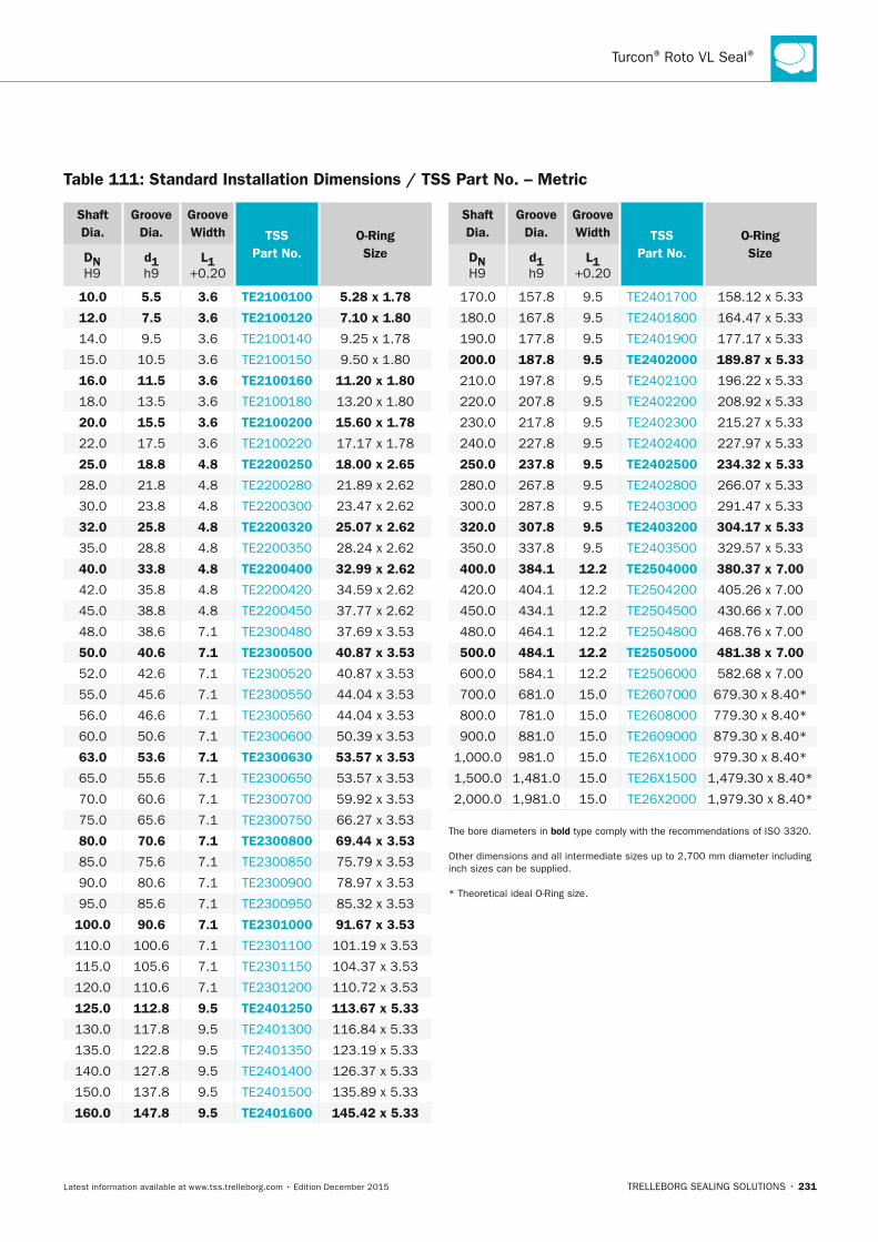
Turcon® Roto VL Seal®
TRELLEBORG SEALING SOLUTIONS • 231Latest information available at www.tss.trelleborg.com • Edition December 2015
Table 111: Standard Installation Dimensions / TSS Part no. – Metric
Shaft Dia.
Groove Dia.
Groove Width TSS
Part no.O-Ring SizeDn
H9d1 h9
L1 +0.20
10.0 5.5 3.6 TE2100100 5.28 x 1.78
12.0 7.5 3.6 TE2100120 7.10 x 1.80
14.0 9.5 3.6 TE2100140 9.25 x 1.78
15.0 10.5 3.6 TE2100150 9.50 x 1.80
16.0 11.5 3.6 TE2100160 11.20 x 1.80
18.0 13.5 3.6 TE2100180 13.20 x 1.80
20.0 15.5 3.6 TE2100200 15.60 x 1.78
22.0 17.5 3.6 TE2100220 17.17 x 1.78
25.0 18.8 4.8 TE2200250 18.00 x 2.65
28.0 21.8 4.8 TE2200280 21.89 x 2.62
30.0 23.8 4.8 TE2200300 23.47 x 2.62
32.0 25.8 4.8 TE2200320 25.07 x 2.62
35.0 28.8 4.8 TE2200350 28.24 x 2.62
40.0 33.8 4.8 TE2200400 32.99 x 2.62
42.0 35.8 4.8 TE2200420 34.59 x 2.62
45.0 38.8 4.8 TE2200450 37.77 x 2.62
48.0 38.6 7.1 TE2300480 37.69 x 3.53
50.0 40.6 7.1 TE2300500 40.87 x 3.53
52.0 42.6 7.1 TE2300520 40.87 x 3.53
55.0 45.6 7.1 TE2300550 44.04 x 3.53
56.0 46.6 7.1 TE2300560 44.04 x 3.53
60.0 50.6 7.1 TE2300600 50.39 x 3.53
63.0 53.6 7.1 TE2300630 53.57 x 3.53
65.0 55.6 7.1 TE2300650 53.57 x 3.53
70.0 60.6 7.1 TE2300700 59.92 x 3.53
75.0 65.6 7.1 TE2300750 66.27 x 3.53
80.0 70.6 7.1 TE2300800 69.44 x 3.53
85.0 75.6 7.1 TE2300850 75.79 x 3.53
90.0 80.6 7.1 TE2300900 78.97 x 3.53
95.0 85.6 7.1 TE2300950 85.32 x 3.53
100.0 90.6 7.1 TE2301000 91.67 x 3.53
110.0 100.6 7.1 TE2301100 101.19 x 3.53
115.0 105.6 7.1 TE2301150 104.37 x 3.53
120.0 110.6 7.1 TE2301200 110.72 x 3.53
125.0 112.8 9.5 TE2401250 113.67 x 5.33
130.0 117.8 9.5 TE2401300 116.84 x 5.33
135.0 122.8 9.5 TE2401350 123.19 x 5.33
140.0 127.8 9.5 TE2401400 126.37 x 5.33
150.0 137.8 9.5 TE2401500 135.89 x 5.33
160.0 147.8 9.5 TE2401600 145.42 x 5.33
Shaft Dia.
Groove Dia.
Groove Width TSS
Part no.O-Ring SizeDn
H9d1 h9
L1 +0.20
170.0 157.8 9.5 TE2401700 158.12 x 5.33
180.0 167.8 9.5 TE2401800 164.47 x 5.33
190.0 177.8 9.5 TE2401900 177.17 x 5.33
200.0 187.8 9.5 TE2402000 189.87 x 5.33
210.0 197.8 9.5 TE2402100 196.22 x 5.33
220.0 207.8 9.5 TE2402200 208.92 x 5.33
230.0 217.8 9.5 TE2402300 215.27 x 5.33
240.0 227.8 9.5 TE2402400 227.97 x 5.33
250.0 237.8 9.5 TE2402500 234.32 x 5.33
280.0 267.8 9.5 TE2402800 266.07 x 5.33
300.0 287.8 9.5 TE2403000 291.47 x 5.33
320.0 307.8 9.5 TE2403200 304.17 x 5.33
350.0 337.8 9.5 TE2403500 329.57 x 5.33
400.0 384.1 12.2 TE2504000 380.37 x 7.00
420.0 404.1 12.2 TE2504200 405.26 x 7.00
450.0 434.1 12.2 TE2504500 430.66 x 7.00
480.0 464.1 12.2 TE2504800 468.76 x 7.00
500.0 484.1 12.2 TE2505000 481.38 x 7.00
600.0 584.1 12.2 TE2506000 582.68 x 7.00
700.0 681.0 15.0 TE2607000 679.30 x 8.40*
800.0 781.0 15.0 TE2608000 779.30 x 8.40*
900.0 881.0 15.0 TE2609000 879.30 x 8.40*
1,000.0 981.0 15.0 TE26X1000 979.30 x 8.40*
1,500.0 1,481.0 15.0 TE26X1500 1,479.30 x 8.40*
2,000.0 1,981.0 15.0 TE26X2000 1,979.30 x 8.40*
The bore diameters in bold type comply with the recommendations of ISO 3320.
Other dimensions and all intermediate sizes up to 2,700 mm diameter including inch sizes can be supplied.
* Theoretical ideal O-Ring size.
FBP_neues_Layout_2015.indb 231 17.10.2016 13:37:28

ROTARY SEALS · Turcon® Roto VL Seal®
232 • TRELLEBORG SEALING SOLUTIONS Latest information available at www.tss.trelleborg.com • Edition December 2015
FBP_neues_Layout_2015.indb 232 17.10.2016 13:37:28
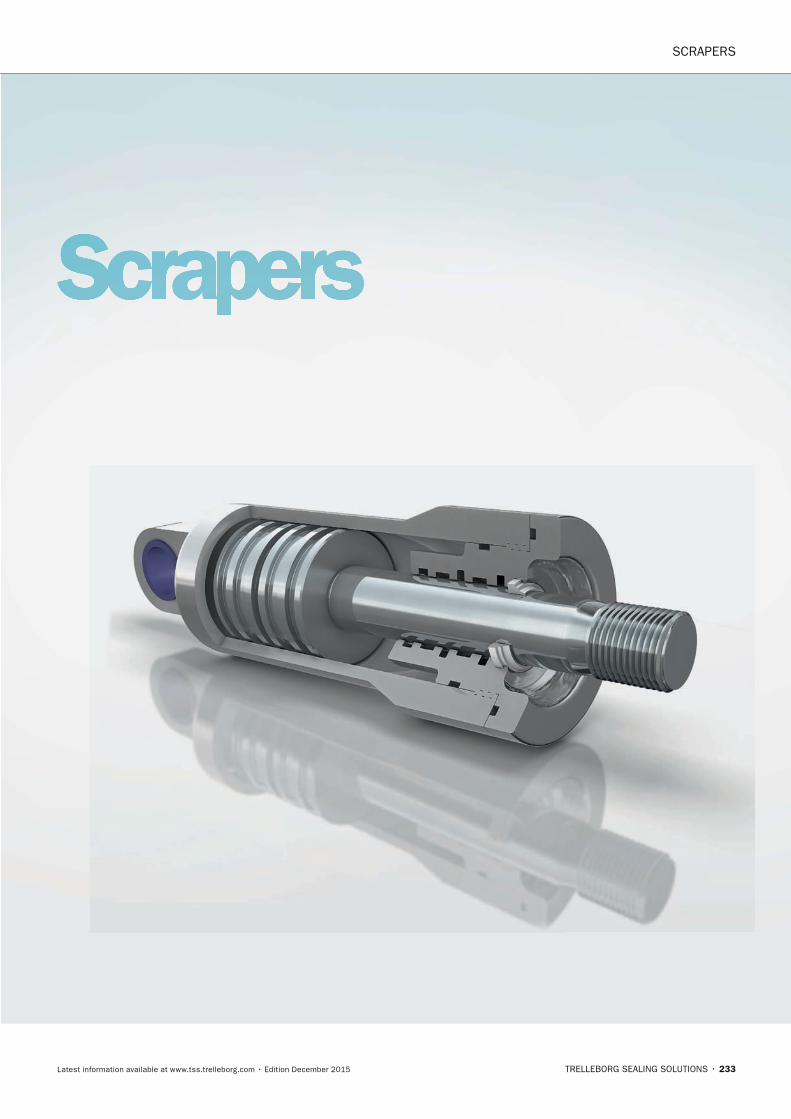
ScraperS
TRELLEBORG SEALING SOLUTIONS • 233Latest information available at www.tss.trelleborg.com • Edition December 2015
Scrapers
FBP_neues_Layout_2015.indb 233 17.10.2016 13:37:34

234 • TRELLEBORG SEALING SOLUTIONS Latest information available at www.tss.trelleborg.com • Edition December 2015
SCRAPERS
FBP_neues_Layout_2015.indb 234 17.10.2016 13:37:34
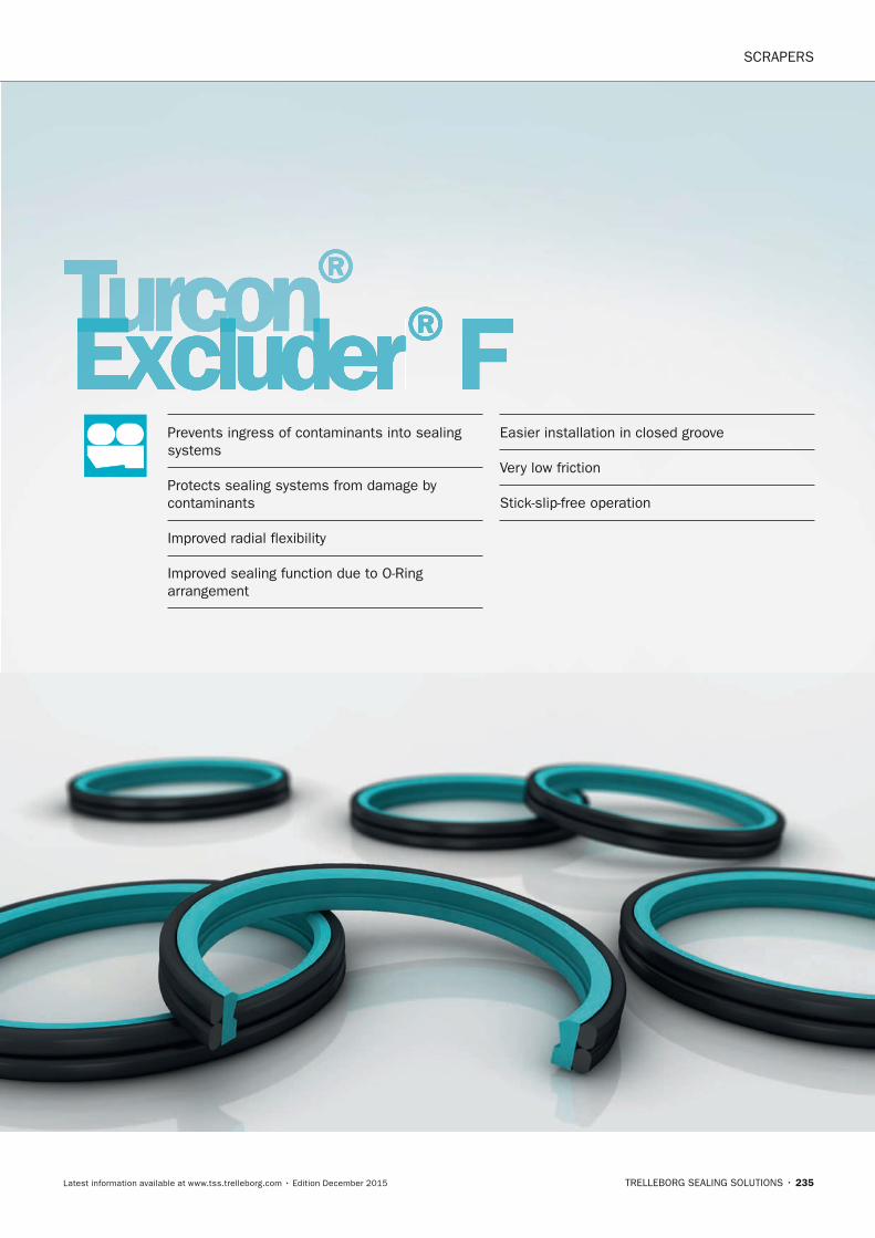
SCRAPERS
TRELLEBORG SEALING SOLUTIONS • 235Latest information available at www.tss.trelleborg.com • Edition December 2015
Turcon®Turcon®TurconExcluderTurconExcluderTurcon ®FPrevents ingress of contaminants into sealing systems
Protects sealing systems from damage by contaminants
Improved radial flexibility
Improved sealing function due to O-Ring arrangement
Easier installation in closed groove
Very low friction
Stick-slip-free operation
FBP_neues_Layout_2015.indb 235 17.10.2016 13:37:36

SCRAPERS · Turcon® Excluder® F
236 • TRELLEBORG SEALING SOLUTIONS Latest information available at www.tss.trelleborg.com • Edition December 2015
FBP_neues_Layout_2015.indb 236 17.10.2016 13:37:36
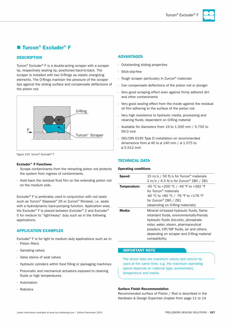
Turcon® Excluder® F
TRELLEBORG SEALING SOLUTIONS • 237Latest information available at www.tss.trelleborg.com • Edition December 2015
� Turcon® Excluder® F
DESCRIPTIOn
Turcon® Excluder® F is a double-acting scraper with a scraper lip, respectively sealing lip, positioned back-to-back. The scraper is installed with two O-Rings as elastic energizing elements. The O-Rings maintain the pressure of the scraper lips against the sliding surface and compensate deflections of the piston rod.
Turcon® Scraper
O-Ring
P
Figure 103: Turcon® Excluder® F
Excluder® F Functions - Scrape contaminants from the retracting piston rod protects
the system from ingress of contaminants.
- Hold back the residual fluid film on the extending piston rod on the medium side.
Excluder® F is preferably used in conjunction with rod seals such as Turcon® Stepseal® 2K or Zurcon® Rimseal, i.e. seals with a hydrodynamic back-pumping function. Application wise, the Excluder® F is placed between Excluder® 2 and Excluder®
5 for medium to "light-heavy" duty such as in the following applications.
APPLICATIOn ExAMPLES
Excluder® F is for light to medium duty applications such as in: - Piston fillers
- Sampling valves
- Valve stems of seat valves
- Hydraulic cylinders within food filling or packaging machines
- Pneumatic and mechanical actuators exposed to cleaning fluids or high temperatures
- Automation
- Robotics
ADVAnTAGES
- Outstanding sliding properties
- Stick-slip-free
- Tough scraper particulary in Zurcon® materials
- Can compensate deflections of the piston rod or plunger
- Very good scraping effect even against firmly adhered dirt and other contaminants
- Very good sealing effect from the inside against the residual oil film adhering to the surface of the piston rod
- Very high resistance to hydraulic media, processing and cleaning fluids; dependent on O-Ring material
- Available for diameters from 19 to 1,500 mm / 0.750 to 59.0 inch
- ISO/DIN 6195 Type D installation on recommended dimensions from ø 40 to ø 140 mm / ø 1.575 to ø 5.512 inch
TECHnICAL DATA
Operating conditions
Speed: 15 m/s / 50 ft/s for Turcon® materials2 m/s / 6.5 ft/s for Zurcon® Z80 / Z81
Temperature: -45 °C to +200 °C / -49 °F to +392 °F for Turcon® materials-60 °C to +80 °C / -76 °F to +176 °F for Zurcon® Z80 / Z81(depending on O-Ring materials)
Media: Mineral oil-based hydraulic fluids, flame retardant fluids, environmentally-friendly hydraulic fluids (bio-oils), phosphate ester, water, steam, pharmaceutical powders, CIP/SIP fluids, air and others, depending on scraper and O-Ring material compatibility.
IMPORTAnT nOTE
The above data are maximum values and cannot be used at the same time. e.g. the maximum operating speed depends on material type, environment, temperature and media.
Surface Finish RecommendationRecommended surface of Piston / Rod is described in the Hardware & Design Expertise chapter from page 11 to 14
FBP_neues_Layout_2015.indb 237 17.10.2016 13:37:37
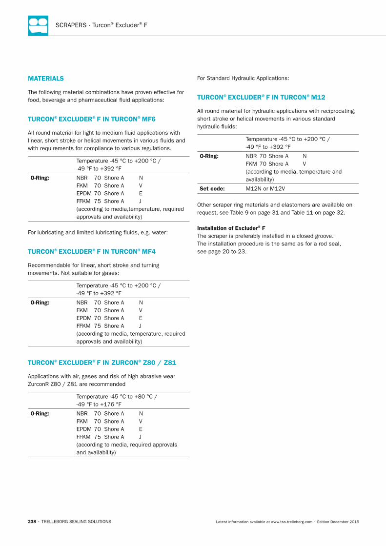
SCRAPERS · Turcon® Excluder® F
238 • TRELLEBORG SEALING SOLUTIONS Latest information available at www.tss.trelleborg.com • Edition December 2015
MATERIALS
The following material combinations have proven effective for food, beverage and pharmaceutical fluid applications:
TURCOn ®ExCLUDER ®F In TURCOn ®MF6
All round material for light to medium fluid applications with linear, short stroke or helical movements in various fluids and with requirements for compliance to various regulations.
Temperature -45 °C to +200 °C / -49 °F to +392 °F
O-Ring: NBR 70 Shore A N FKM 70 Shore A V EPDM 70 Shore A E FFKM 75 Shore A J (according to media,temperature, required approvals and availability)
For lubricating and limited lubricating fluids, e.g. water:
TURCOn®ExCLUDER®F In TURCOn ®MF4
Recommendable for linear, short stroke and turning movements. Not suitable for gases:
Temperature -45 °C to +200 °C / -49 °F to +392 °F
O-Ring: NBR 70 Shore A N FKM 70 Shore A V EPDM 70 Shore A E FFKM 75 Shore A J (according to media, temperature, required approvals and availability)
TURCOn®ExCLUDER®F In ZURCOn ®Z80 / Z81
Applications with air, gases and risk of high abrasive wear ZurconR Z80 / Z81 are recommended
Temperature -45 °C to +80 °C / -49 °F to +176 °F
O-Ring: NBR 70 Shore A N FKM 70 Shore A V EPDM 70 Shore A E FFKM 75 Shore A J (according to media, required approvals and availability)
For Standard Hydraulic Applications:
TURCOn®ExCLUDER®F In TURCOn®M12
All round material for hydraulic applications with reciprocating, short stroke or helical movements in various standard hydraulic fluids:
Temperature -45 °C to +200 °C / -49 °F to +392 °F
O-Ring: NBR 70 Shore A N FKM 70 Shore A V (according to media, temperature and availability)
Set code: M12N or M12V
Other scraper ring materials and elastomers are available on request, see Table 9 on page 31 and Table 11 on page 32.
Installation of Excluder® FThe scraper is preferably installed in a closed groove. The installation procedure is the same as for a rod seal, see page 20 to 23.
FBP_neues_Layout_2015.indb 238 17.10.2016 13:37:37

Turcon® Excluder® F
TRELLEBORG SEALING SOLUTIONS • 239Latest information available at www.tss.trelleborg.com • Edition December 2015
FBP_neues_Layout_2015.indb 239 17.10.2016 13:37:37
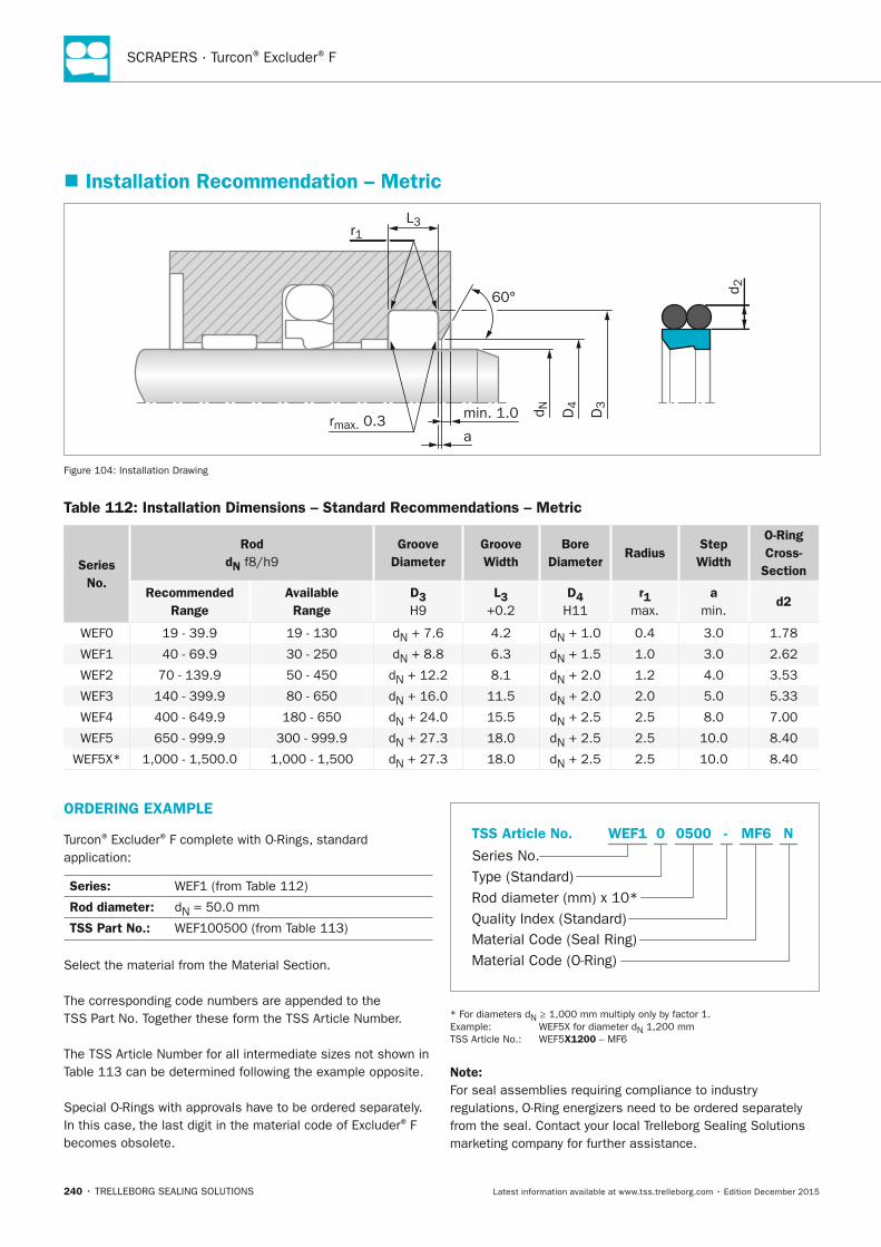
SCRAPERS · Turcon® Excluder® F
240 • TRELLEBORG SEALING SOLUTIONS Latest information available at www.tss.trelleborg.com • Edition December 2015
� Installation Recommendation – Metric
60° d 2
L3
rmax. 0.3
r1
D3
D4
d Nmin. 1.0
a
Figure 104: Installation Drawing
Table 112: Installation Dimensions – Standard Recommendations – Metric
Series no.
Rod dn f8/h9
Groove Diameter
Groove Width
Bore Diameter
RadiusStep Width
O-Ring Cross-
Section
Recommended Range
Available Range
D3H9
L3+0.2
D4H11
r1max.
amin.
d2
WEF0 19 - 39.9 19 - 130 dN + 7.6 4.2 dN + 1.0 0.4 3.0 1.78
WEF1 40 - 69.9 30 - 250 dN + 8.8 6.3 dN + 1.5 1.0 3.0 2.62
WEF2 70 - 139.9 50 - 450 dN + 12.2 8.1 dN + 2.0 1.2 4.0 3.53
WEF3 140 - 399.9 80 - 650 dN + 16.0 11.5 dN + 2.0 2.0 5.0 5.33
WEF4 400 - 649.9 180 - 650 dN + 24.0 15.5 dN + 2.5 2.5 8.0 7.00
WEF5 650 - 999.9 300 - 999.9 dN + 27.3 18.0 dN + 2.5 2.5 10.0 8.40
WEF5X* 1,000 - 1,500.0 1,000 - 1,500 dN + 27.3 18.0 dN + 2.5 2.5 10.0 8.40
ORDERInG ExAMPLE
Turcon® Excluder® F complete with O-Rings, standard application:
Series: WEF1 (from Table 112)
Rod diameter: dN = 50.0 mm
TSS Part no.: WEF100500 (from Table 113)
Select the material from the Material Section.
The corresponding code numbers are appended to the TSS Part No. Together these form the TSS Article Number.
The TSS Article Number for all intermediate sizes not shown in Table 113 can be determined following the example opposite.
Special O-Rings with approvals have to be ordered separately. In this case, the last digit in the material code of Excluder® F becomes obsolete.
Material Code (Seal Ring)
Series No.
TSS Article No.
Material Code (O-Ring)
Rod diameter (mm) x 10*Quality Index (Standard)
Type (Standard)
MF6 NWEF1 -0 0500
* For diameters dN ≥ 1,000 mm multiply only by factor 1. Example: WEF5X for diameter dN 1,200 mm TSS Article No.: WEF5x1200 – MF6
note:For seal assemblies requiring compliance to industry regulations, O-Ring energizers need to be ordered separately from the seal. Contact your local Trelleborg Sealing Solutions marketing company for further assistance.
FBP_neues_Layout_2015.indb 240 17.10.2016 13:37:38
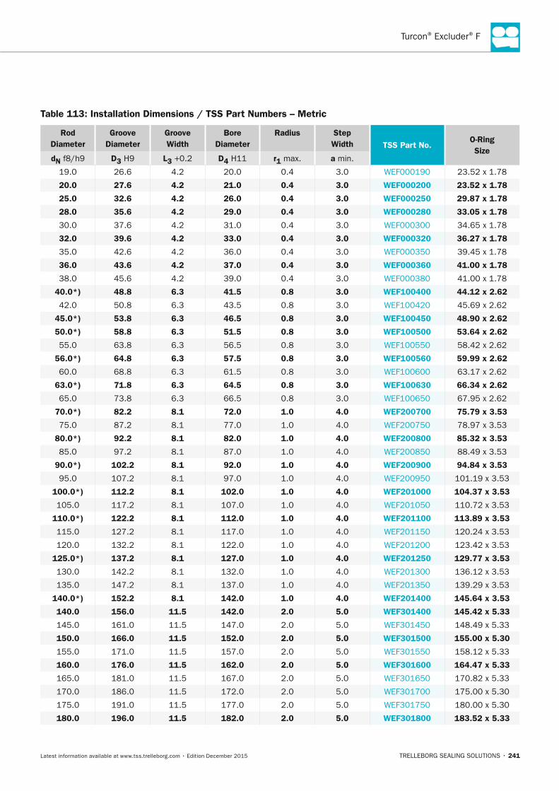
Turcon® Excluder® F
TRELLEBORG SEALING SOLUTIONS • 241Latest information available at www.tss.trelleborg.com • Edition December 2015
Table 113: Installation Dimensions / TSS Part numbers – Metric
Rod Diameter
Groove Diameter
Groove Width
Bore Diameter
Radius Step Width TSS Part no.
O-Ring Size
dn f8/h9 D3 H9 L3 +0.2 D4 H11 r1 max. a min.
19.0 26.6 4.2 20.0 0.4 3.0 WEF000190 23.52 x 1.78
20.0 27.6 4.2 21.0 0.4 3.0 WEF000200 23.52 x 1.78
25.0 32.6 4.2 26.0 0.4 3.0 WEF000250 29.87 x 1.78
28.0 35.6 4.2 29.0 0.4 3.0 WEF000280 33.05 x 1.78
30.0 37.6 4.2 31.0 0.4 3.0 WEF000300 34.65 x 1.78
32.0 39.6 4.2 33.0 0.4 3.0 WEF000320 36.27 x 1.78
35.0 42.6 4.2 36.0 0.4 3.0 WEF000350 39.45 x 1.78
36.0 43.6 4.2 37.0 0.4 3.0 WEF000360 41.00 x 1.78
38.0 45.6 4.2 39.0 0.4 3.0 WEF000380 41.00 x 1.78
40.0*) 48.8 6.3 41.5 0.8 3.0 WEF100400 44.12 x 2.62
42.0 50.8 6.3 43.5 0.8 3.0 WEF100420 45.69 x 2.62
45.0*) 53.8 6.3 46.5 0.8 3.0 WEF100450 48.90 x 2.62
50.0*) 58.8 6.3 51.5 0.8 3.0 WEF100500 53.64 x 2.62
55.0 63.8 6.3 56.5 0.8 3.0 WEF100550 58.42 x 2.62
56.0*) 64.8 6.3 57.5 0.8 3.0 WEF100560 59.99 x 2.62
60.0 68.8 6.3 61.5 0.8 3.0 WEF100600 63.17 x 2.62
63.0*) 71.8 6.3 64.5 0.8 3.0 WEF100630 66.34 x 2.62
65.0 73.8 6.3 66.5 0.8 3.0 WEF100650 67.95 x 2.62
70.0*) 82.2 8.1 72.0 1.0 4.0 WEF200700 75.79 x 3.53
75.0 87.2 8.1 77.0 1.0 4.0 WEF200750 78.97 x 3.53
80.0*) 92.2 8.1 82.0 1.0 4.0 WEF200800 85.32 x 3.53
85.0 97.2 8.1 87.0 1.0 4.0 WEF200850 88.49 x 3.53
90.0*) 102.2 8.1 92.0 1.0 4.0 WEF200900 94.84 x 3.53
95.0 107.2 8.1 97.0 1.0 4.0 WEF200950 101.19 x 3.53
100.0*) 112.2 8.1 102.0 1.0 4.0 WEF201000 104.37 x 3.53
105.0 117.2 8.1 107.0 1.0 4.0 WEF201050 110.72 x 3.53
110.0*) 122.2 8.1 112.0 1.0 4.0 WEF201100 113.89 x 3.53
115.0 127.2 8.1 117.0 1.0 4.0 WEF201150 120.24 x 3.53
120.0 132.2 8.1 122.0 1.0 4.0 WEF201200 123.42 x 3.53
125.0*) 137.2 8.1 127.0 1.0 4.0 WEF201250 129.77 x 3.53
130.0 142.2 8.1 132.0 1.0 4.0 WEF201300 136.12 x 3.53
135.0 147.2 8.1 137.0 1.0 4.0 WEF201350 139.29 x 3.53
140.0*) 152.2 8.1 142.0 1.0 4.0 WEF201400 145.64 x 3.53
140.0 156.0 11.5 142.0 2.0 5.0 WEF301400 145.42 x 5.33
145.0 161.0 11.5 147.0 2.0 5.0 WEF301450 148.49 x 5.33
150.0 166.0 11.5 152.0 2.0 5.0 WEF301500 155.00 x 5.30
155.0 171.0 11.5 157.0 2.0 5.0 WEF301550 158.12 x 5.33
160.0 176.0 11.5 162.0 2.0 5.0 WEF301600 164.47 x 5.33
165.0 181.0 11.5 167.0 2.0 5.0 WEF301650 170.82 x 5.33
170.0 186.0 11.5 172.0 2.0 5.0 WEF301700 175.00 x 5.30
175.0 191.0 11.5 177.0 2.0 5.0 WEF301750 180.00 x 5.30
180.0 196.0 11.5 182.0 2.0 5.0 WEF301800 183.52 x 5.33
FBP_neues_Layout_2015.indb 241 17.10.2016 13:37:39
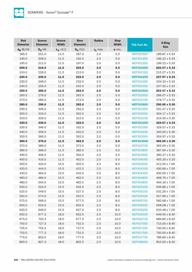
SCRAPERS · Turcon® Excluder® F
242 • TRELLEBORG SEALING SOLUTIONS Latest information available at www.tss.trelleborg.com • Edition December 2015
Rod Diameter
Groove Diameter
Groove Width
Bore Diameter
Radius Step Width TSS Part no.
O-Ring Size
dn f8/h9 D3 H9 L3 +0.2 D4 H11 r1 max. a min.
185.0 201.0 11.5 187.0 2.0 5.0 WEF301850 189.87 x 5.33
190.0 206.0 11.5 192.0 2.0 5.0 WEF301900 196.22 x 5.33
195.0 211.0 11.5 197.0 2.0 5.0 WEF301950 196.22 x 5.33
200.0 216.0 11.5 202.0 2.0 5.0 WEF302000 202.57 x 5.33
210.0 226.0 11.5 212.0 2.0 5.0 WEF302100 215.27 x 5.33
220.0 236.0 11.5 222.0 2.0 5.0 WEF302200 227.97 x 5.33
230.0 246.0 11.5 232.0 2.0 5.0 WEF302300 234.32 x 5.33
240.0 256.0 11.5 242.0 2.0 5.0 WEF302400 247.02 x 5.33
250.0 266.0 11.5 252.0 2.0 5.0 WEF302500 253.37 x 5.33
260.0 276.0 11.5 262.0 2.0 5.0 WEF302600 266.07 x 5.33
270.0 286.0 11.5 272.0 2.0 5.0 WEF302700 278.77 x 5.33
280.0 296.0 11.5 282.0 2.0 5.0 WEF302800 290.00 x 5.30
290.0 306.0 11.5 292.0 2.0 5.0 WEF302900 291.47 x 5.33
300.0 316.0 11.5 302.0 2.0 5.0 WEF303000 304.17 x 5.33
310.0 326.0 11.5 312.0 2.0 5.0 WEF303100 315.00 x 5.30
320.0 336.0 11.5 322.0 2.0 5.0 WEF303200 329.57 x 5.33
330.0 346.0 11.5 332.0 2.0 5.0 WEF303300 329.57 x 5.33
340.0 356.0 11.5 342.0 2.0 5.0 WEF303400 345.00 x 5.30
350.0 366.0 11.5 352.0 2.0 5.0 WEF303500 354.97 x 5.33
360.0 376.0 11.5 362.0 2.0 5.0 WEF303600 365.00 x 5.30
370.0 386.0 11.5 372.0 2.0 5.0 WEF303700 365.00 x 5.30
380.0 396.0 11.5 382.0 2.0 5.0 WEF303800 387.00 x 5.30
390.0 406.0 11.5 392.0 2.0 5.0 WEF303900 380.37 x 5.33
400.0 416.0 11.5 402.0 2.0 5.0 WEF304000 405.26 x 5.33
400.0 424.0 15.5 402.5 2.5 8.0 WEF404000 412.00 x 7.00
420.0 444.0 15.5 422.5 2.5 8.0 WEF404200 430.66 x 7.00
440.0 464.0 15.5 442.5 2.5 8.0 WEF404400 450.00 x 7.00
460.0 484.0 15.5 462.5 2.5 8.0 WEF404600 468.76 x 7.00
480.0 504.0 15.5 482.5 2.5 8.0 WEF404800 494.16 x 7.00
500.0 524.0 15.5 502.5 2.5 8.0 WEF405000 506.86 x 7.00
525.0 549.0 15.5 527.5 2.5 8.0 WEF405250 532.26 x 7.00
550.0 574.0 15.5 552.5 2.5 8.0 WEF405500 557.66 x 7.00
575.0 599.0 15.5 577.5 2.5 8.0 WEF405750 582.68 x 7.00
600.0 624.0 15.5 602.5 2.5 8.0 WEF406000 608.08 x 7.00
625.0 649.0 15.5 627.5 2.5 8.0 WEF406250 633.48 x 7.00
650.0 677.3 18.0 652.5 2.5 10.0 WEF506500 649.00 x 8.40
675.0 702.3 18.0 677.5 2.5 10.0 WEF506750 686.80 x 8.40
700.0 727.3 18.0 702.5 2.5 10.0 WEF507000 715.00 x 8.40
725.0 752.3 18.0 727.5 2.5 10.0 WEF507250 740.00 x 8.40
750.0 777.3 18.0 752.5 2.5 10.0 WEF507500 760.00 x 8.40
775.0 802.0 18.0 777.5 2.5 10.0 WEF507750 786.80 x 8.40
800.0 827.3 18.0 802.5 2.5 10.0 WEF508000 810.00 x 8.40
FBP_neues_Layout_2015.indb 242 17.10.2016 13:37:39
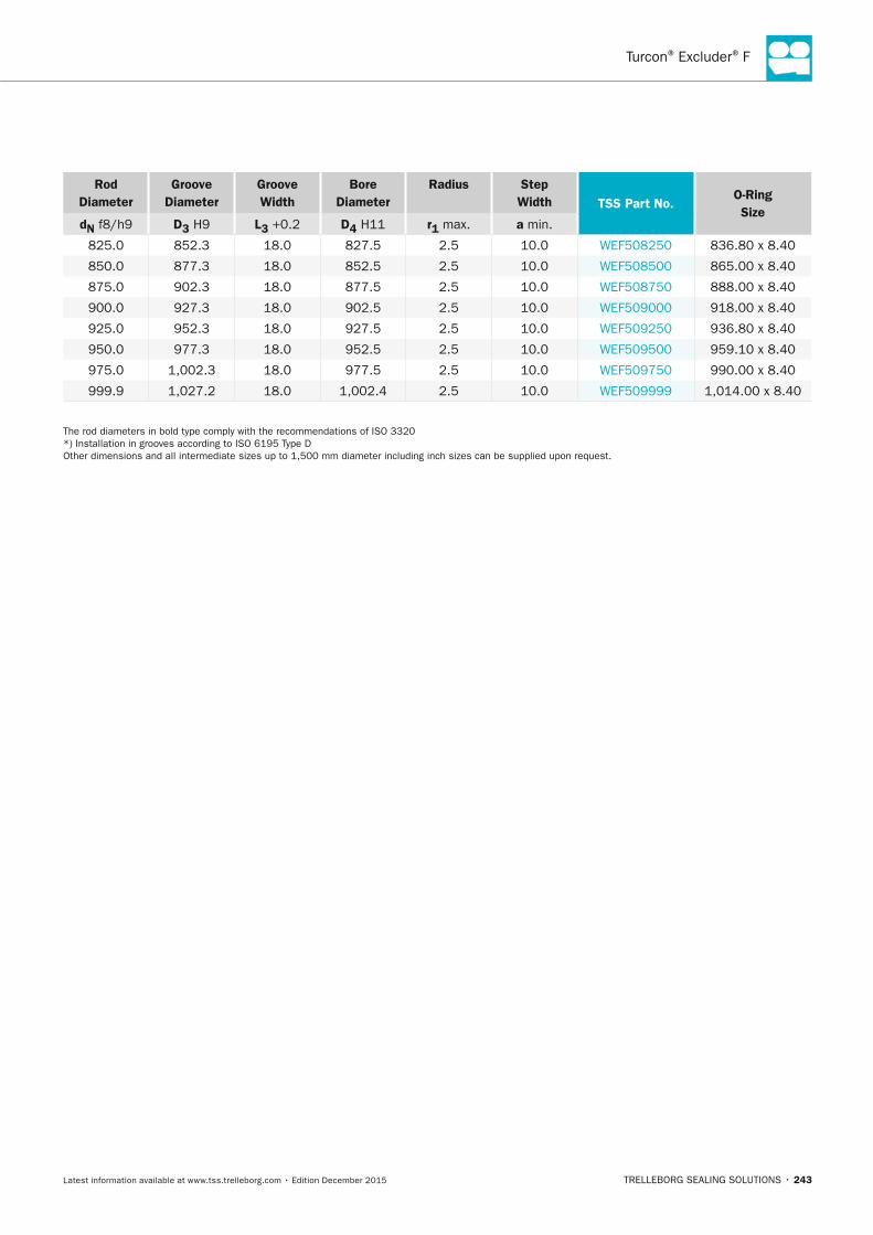
Turcon® Excluder® F
TRELLEBORG SEALING SOLUTIONS • 243Latest information available at www.tss.trelleborg.com • Edition December 2015
Rod Diameter
Groove Diameter
Groove Width
Bore Diameter
Radius Step Width TSS Part no.
O-Ring Size
dn f8/h9 D3 H9 L3 +0.2 D4 H11 r1 max. a min.
825.0 852.3 18.0 827.5 2.5 10.0 WEF508250 836.80 x 8.40
850.0 877.3 18.0 852.5 2.5 10.0 WEF508500 865.00 x 8.40
875.0 902.3 18.0 877.5 2.5 10.0 WEF508750 888.00 x 8.40
900.0 927.3 18.0 902.5 2.5 10.0 WEF509000 918.00 x 8.40
925.0 952.3 18.0 927.5 2.5 10.0 WEF509250 936.80 x 8.40
950.0 977.3 18.0 952.5 2.5 10.0 WEF509500 959.10 x 8.40
975.0 1,002.3 18.0 977.5 2.5 10.0 WEF509750 990.00 x 8.40
999.9 1,027.2 18.0 1,002.4 2.5 10.0 WEF509999 1,014.00 x 8.40
The rod diameters in bold type comply with the recommendations of ISO 3320*) Installation in grooves according to ISO 6195 Type DOther dimensions and all intermediate sizes up to 1,500 mm diameter including inch sizes can be supplied upon request.
FBP_neues_Layout_2015.indb 243 17.10.2016 13:37:39
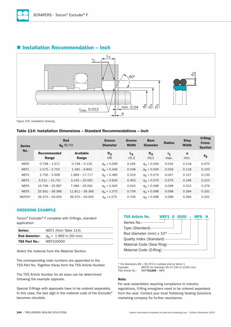
SCRAPERS · Turcon® Excluder® F
244 • TRELLEBORG SEALING SOLUTIONS Latest information available at www.tss.trelleborg.com • Edition December 2015
� Installation Recommendation – Inch
60° d 2
L3
rmax. 0.012
r1
D3
D4
d Nmin. 0.04
a
Figure 105: Installation Drawing
Table 114: Installation Dimensions – Standard Recommendations – Inch
Series no.
Rod dn f8/h9
Groove Diameter
Groove Width
Bore Diameter
RadiusStep Width
O-Ring Cross-
Section
Recommended Range
Available Range
D3 H9
L3 +0.2
D4 H11
r1 max.
a min.
d2
WEF0 0.748 – 1.571 0.748 – 5.118 dN + 0.299 0.165 dN + 0.039 0.016 0.118 0.070
WEF1 1.575 – 2.752 1.181 – 9.843 dN + 0.346 0.248 dN + 0.059 0.039 0.118 0.103
WEF2 2.756 – 5.508 1.969 – 17.717 dN + 0.480 0.319 dN + 0.079 0.047 0.157 0.139
WEF3 5.512 – 15.741 3.150 – 25.591 dN + 0.630 0.453 dN + 0.079 0.079 0.196 0.210
WEF4 15.748 – 25.587 7.086 – 25.591 dN + 0.945 0.610 dN + 0.098 0.098 0.315 0.276
WEF5 25.591 – 39.366 11.811 – 39.366 dN + 1.075 0.709 dN + 0.098 0.098 0.394 0.331
WEF5X* 39.370 – 59.055 39.370 – 59.055 dN +1.075 0.709 dN + 0.098 0.098 0.394 0.331
ORDERInG ExAMPLE
Turcon® Excluder® F complete with O-Rings, standard application:
Series: WEF1 (from Table 114)
Rod diameter: dN = 1.969 in (50 mm)
TSS Part no.: WEF100500
Select the material from the Material Section.
The corresponding code numbers are appended to the TSS Part No. Together these form the TSS Article Number.
The TSS Article Number for all sizes can be determined following the example opposite.
Special O-Rings with approvals have to be ordered separately. In this case, the last digit in the material code of the Excluder®
becomes obsolete.
Material Code (Seal Ring)
Series No.
TSS Article No.
Material Code (O-Ring)
Rod diameter (mm) x 10*Quality Index (Standard)
Type (Standard)
MF6 NWEF1 -0 0500
* For diameters dN ≥ 39.370 in multiply only by factor 1 Example: WEF5X for diameter dN 47.244 in (1200 mm) TSS Article No.: WEF5x1200 – MF6
note:For seal assemblies requiring compliance to industry regulations, O-Ring energizers need to be ordered separately from the seal. Contact your local Trelleborg Sealing Solutions marketing company for further assistance.
FBP_neues_Layout_2015.indb 244 17.10.2016 13:37:40
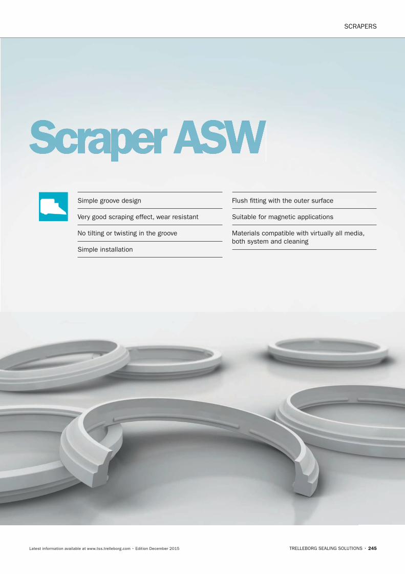
SCRAPERS
TRELLEBORG SEALING SOLUTIONS • 245Latest information available at www.tss.trelleborg.com • Edition December 2015
Scraper ASWSimple groove design
Very good scraping effect, wear resistant
No tilting or twisting in the groove
Simple installation
Flush fitting with the outer surface
Suitable for magnetic applications
Materials compatible with virtually all media, both system and cleaning
FBP_neues_Layout_2015.indb 245 17.10.2016 13:37:43

SCRAPERS · Scraper ASW
246 • TRELLEBORG SEALING SOLUTIONS Latest information available at www.tss.trelleborg.com • Edition December 2015
FBP_neues_Layout_2015.indb 246 17.10.2016 13:37:43
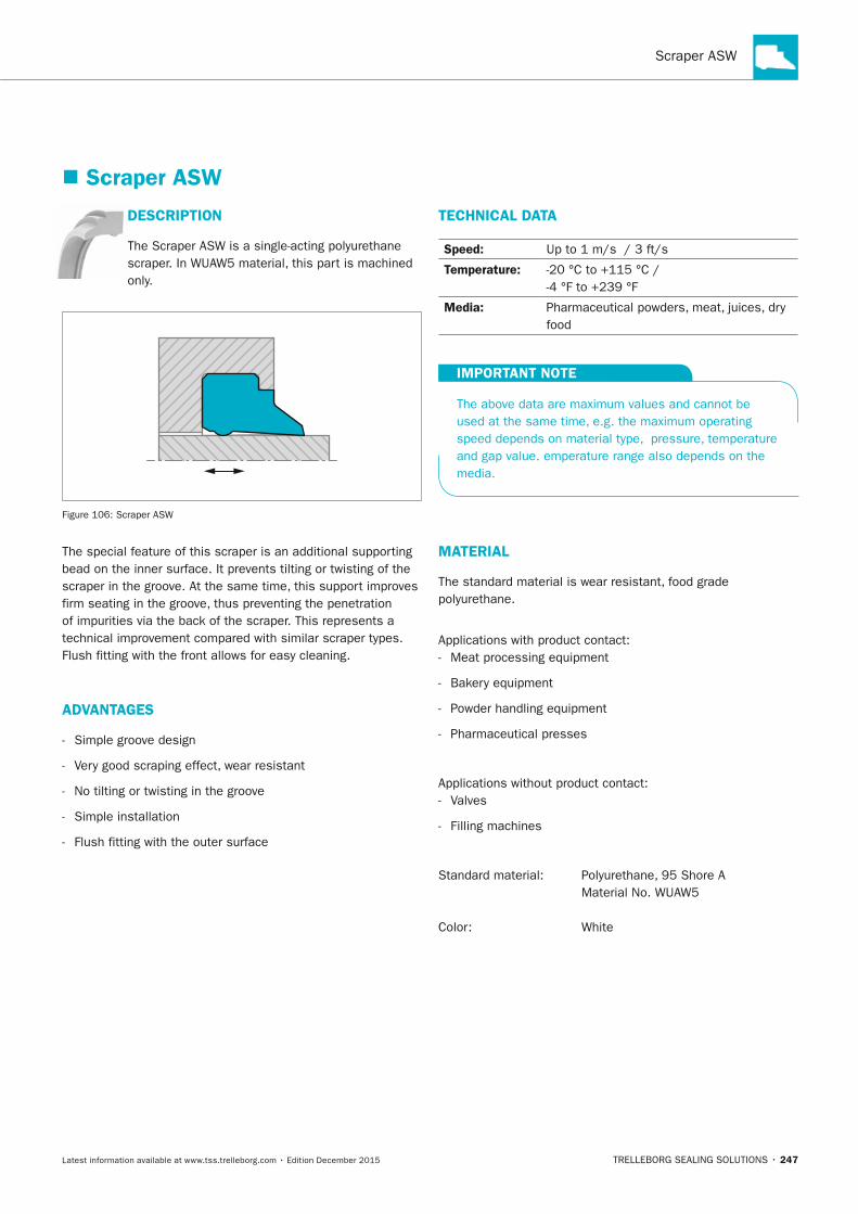
Scraper ASW
TRELLEBORG SEALING SOLUTIONS • 247Latest information available at www.tss.trelleborg.com • Edition December 2015
� Scraper ASW
DESCRIPTIOn
The Scraper ASW is a single-acting polyurethane scraper. In WUAW5 material, this part is machined only.
Figure 106: Scraper ASW
The special feature of this scraper is an additional supporting bead on the inner surface. It prevents tilting or twisting of the scraper in the groove. At the same time, this support improves firm seating in the groove, thus preventing the penetration of impurities via the back of the scraper. This represents a technical improvement compared with similar scraper types. Flush fitting with the front allows for easy cleaning.
ADVAnTAGES
- Simple groove design
- Very good scraping effect, wear resistant
- No tilting or twisting in the groove
- Simple installation
- Flush fitting with the outer surface
TECHnICAL DATA
Speed: Up to 1 m/s / 3 ft/s
Temperature: -20 °C to +115 °C / -4 °F to +239 °F
Media: Pharmaceutical powders, meat, juices, dry food
IMPORTAnT nOTE
The above data are maximum values and cannot be used at the same time, e.g. the maximum operating speed depends on material type, pressure, temperature and gap value. emperature range also depends on the media.
MATERIAL
The standard material is wear resistant, food grade polyurethane.
Applications with product contact: - Meat processing equipment
- Bakery equipment
- Powder handling equipment
- Pharmaceutical presses
Applications without product contact: - Valves
- Filling machines
Standard material: Polyurethane, 95 Shore A Material No. WUAW5
Color: White
FBP_neues_Layout_2015.indb 247 17.10.2016 13:37:44
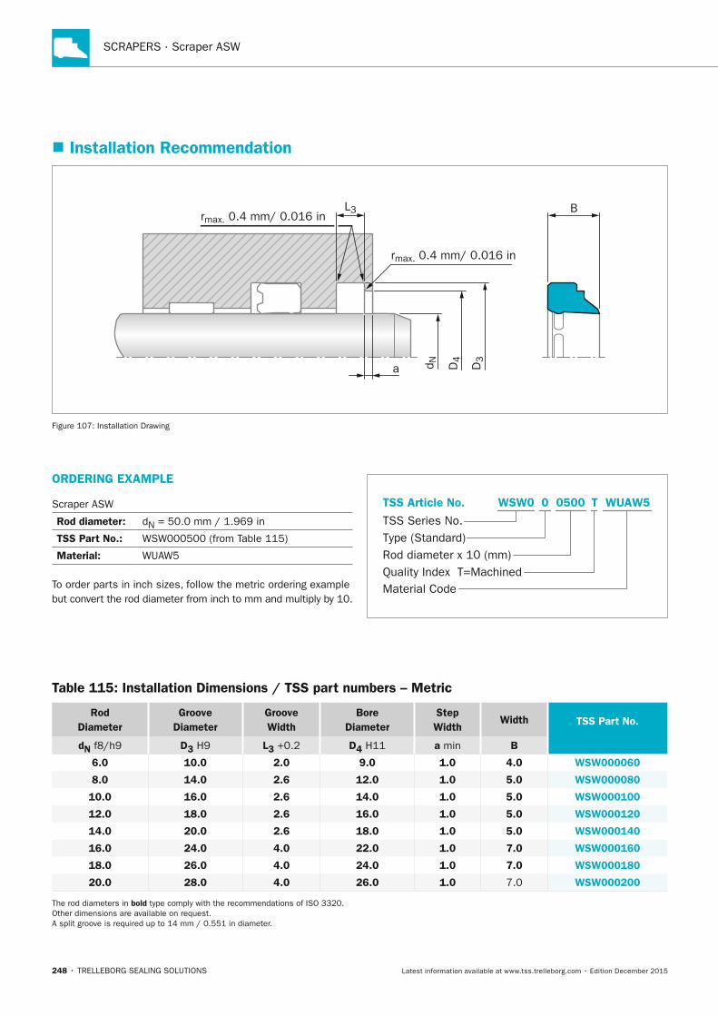
SCRAPERS · Scraper ASW
248 • TRELLEBORG SEALING SOLUTIONS Latest information available at www.tss.trelleborg.com • Edition December 2015
� Installation Recommendation
D4
d N
L3rmax. 0.4 mm/ 0.016 in
rmax. 0.4 mm/ 0.016 in
a
B
D3
Figure 107: Installation Drawing
ORDERInG ExAMPLE
Scraper ASW
Rod diameter: dN = 50.0 mm / 1.969 in
TSS Part no.: WSW000500 (from Table 115)
Material: WUAW5
To order parts in inch sizes, follow the metric ordering example but convert the rod diameter from inch to mm and multiply by 10.
Material Code
TSS Series No.
TSS Article No.
Rod diameter x 10 (mm)Quality Index T=Machined
Type (Standard)
WUAW5WSW0 T0 0500
Table 115: Installation Dimensions / TSS part numbers – Metric
Rod Diameter
Groove Diameter
Groove Width
Bore Diameter
Step Width
Width TSS Part no.
dn f8/h9 D3 H9 L3 +0.2 D4 H11 a min B
6.0 10.0 2.0 9.0 1.0 4.0 WSW000060
8.0 14.0 2.6 12.0 1.0 5.0 WSW000080
10.0 16.0 2.6 14.0 1.0 5.0 WSW000100
12.0 18.0 2.6 16.0 1.0 5.0 WSW000120
14.0 20.0 2.6 18.0 1.0 5.0 WSW000140
16.0 24.0 4.0 22.0 1.0 7.0 WSW000160
18.0 26.0 4.0 24.0 1.0 7.0 WSW000180
20.0 28.0 4.0 26.0 1.0 7.0 WSW000200
The rod diameters in bold type comply with the recommendations of ISO 3320. Other dimensions are available on request. A split groove is required up to 14 mm / 0.551 in diameter.
FBP_neues_Layout_2015.indb 248 17.10.2016 13:37:45
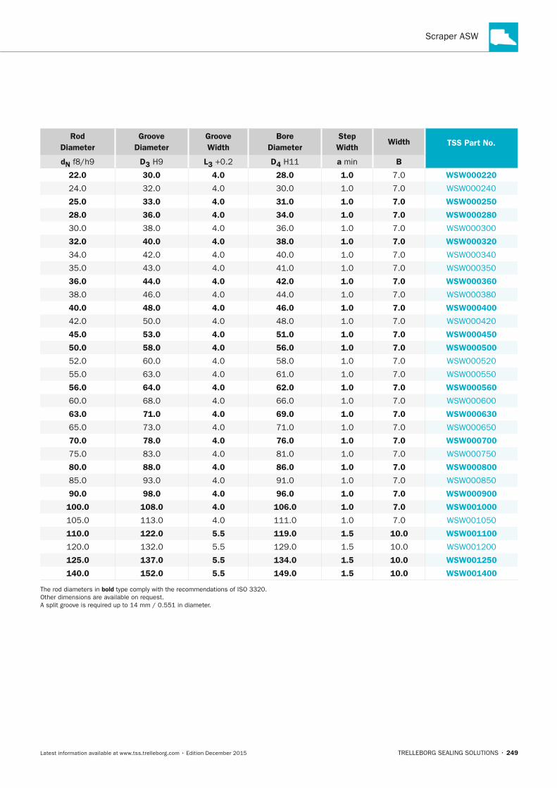
Scraper ASW
TRELLEBORG SEALING SOLUTIONS • 249Latest information available at www.tss.trelleborg.com • Edition December 2015
Rod Diameter
Groove Diameter
Groove Width
Bore Diameter
Step Width
Width TSS Part no.
dn f8/h9 D3 H9 L3 +0.2 D4 H11 a min B
22.0 30.0 4.0 28.0 1.0 7.0 WSW000220
24.0 32.0 4.0 30.0 1.0 7.0 WSW000240
25.0 33.0 4.0 31.0 1.0 7.0 WSW000250
28.0 36.0 4.0 34.0 1.0 7.0 WSW000280
30.0 38.0 4.0 36.0 1.0 7.0 WSW000300
32.0 40.0 4.0 38.0 1.0 7.0 WSW000320
34.0 42.0 4.0 40.0 1.0 7.0 WSW000340
35.0 43.0 4.0 41.0 1.0 7.0 WSW000350
36.0 44.0 4.0 42.0 1.0 7.0 WSW000360
38.0 46.0 4.0 44.0 1.0 7.0 WSW000380
40.0 48.0 4.0 46.0 1.0 7.0 WSW000400
42.0 50.0 4.0 48.0 1.0 7.0 WSW000420
45.0 53.0 4.0 51.0 1.0 7.0 WSW000450
50.0 58.0 4.0 56.0 1.0 7.0 WSW000500
52.0 60.0 4.0 58.0 1.0 7.0 WSW000520
55.0 63.0 4.0 61.0 1.0 7.0 WSW000550
56.0 64.0 4.0 62.0 1.0 7.0 WSW000560
60.0 68.0 4.0 66.0 1.0 7.0 WSW000600
63.0 71.0 4.0 69.0 1.0 7.0 WSW000630
65.0 73.0 4.0 71.0 1.0 7.0 WSW000650
70.0 78.0 4.0 76.0 1.0 7.0 WSW000700
75.0 83.0 4.0 81.0 1.0 7.0 WSW000750
80.0 88.0 4.0 86.0 1.0 7.0 WSW000800
85.0 93.0 4.0 91.0 1.0 7.0 WSW000850
90.0 98.0 4.0 96.0 1.0 7.0 WSW000900
100.0 108.0 4.0 106.0 1.0 7.0 WSW001000
105.0 113.0 4.0 111.0 1.0 7.0 WSW001050
110.0 122.0 5.5 119.0 1.5 10.0 WSW001100
120.0 132.0 5.5 129.0 1.5 10.0 WSW001200
125.0 137.0 5.5 134.0 1.5 10.0 WSW001250
140.0 152.0 5.5 149.0 1.5 10.0 WSW001400
The rod diameters in bold type comply with the recommendations of ISO 3320. Other dimensions are available on request. A split groove is required up to 14 mm / 0.551 in diameter.
FBP_neues_Layout_2015.indb 249 17.10.2016 13:37:45

SCRAPERS · Scraper ASW
250 • TRELLEBORG SEALING SOLUTIONS Latest information available at www.tss.trelleborg.com • Edition December 2015
FBP_neues_Layout_2015.indb 250 17.10.2016 13:37:46
Bearings
TRELLEBORG SEALING SOLUTIONS • 251Latest information available at www.tss.trelleborg.com • Edition December 2015
Bearings
FBP_neues_Layout_2015.indb 251 17.10.2016 13:37:47

252 • TRELLEBORG SEALING SOLUTIONS Latest information available at www.tss.trelleborg.com • Edition December 2015
BEARINGS
FBP_neues_Layout_2015.indb 252 17.10.2016 13:37:47
BEARINGS
TRELLEBORG SEALING SOLUTIONS • 253Latest information available at www.tss.trelleborg.com • Edition December 2015
Slydring® Slydring® Slydring -Wear RingSlydringWear RingSlydring
Prevent metal-to-metal contact
High load bearing capacity in both static and dynamic operation
Even distribution of high radial forces
Very wear resistant, providing long service life
Low friction characteristics
Damp mechanical vibrations
Easy installation
FBP_neues_Layout_2015.indb 253 17.10.2016 13:37:50

BEARINGS · Slydring® - Wear Ring
254 • TRELLEBORG SEALING SOLUTIONS Latest information available at www.tss.trelleborg.com • Edition December 2015
FBP_neues_Layout_2015.indb 254 17.10.2016 13:37:50
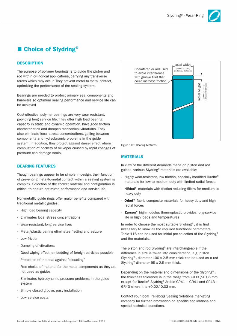
Slydring® - Wear Ring
TRELLEBORG SEALING SOLUTIONS • 255Latest information available at www.tss.trelleborg.com • Edition December 2015
� Choice of Slydring®
DESCRIPTIOn
The purpose of polymer bearings is to guide the piston and rod within cylindrical applications, carrying any transverse forces which may occur. They prevent metal-to-metal contact, optimizing the performance of the sealing system.
Bearings are needed to protect primary seal components and hardware so optimum sealing performance and service life can be achieved.
Cost-effective, polymer bearings are very wear resistant, providing long service life. They offer high load bearing capacity in static and dynamic operation, have good friction characteristics and dampen mechanical vibrations. They also eliminate local stress concentrations, galling between components and hydrodynamic problems in the guide system. In addition, they protect against diesel effect where combustion of pockets of oil vapor caused by rapid changes of pressure can damage seals.
BEARInG FEATURES
Though bearings appear to be simple in design, their function of preventing metal-to-metal contact within a sealing system is complex. Selection of the correct material and configuration is critical to ensure optimized performance and service life.
Non-metallic guide rings offer major benefits compared with traditional metallic guides:
- High load bearing capacity
- Eliminates local stress concentrations
- Wear-resistant, long service lives
- Metal/plastic pairing eliminates fretting and seizure
- Low friction
- Damping of vibrations
- Good wiping effect, embedding of foreign particles possible
- Protection of the seal against "dieseling"
- Free choice of material for the metal components as they are not used as guides
- Eliminates hydrodynamic pressure problems in the guide system
- Simple closed groove, easy installation
- Low service costs
Chamfered or radiused to avoid interferencewith groove �llet thatcould increase friction.
radi
al h
eigh
t(+
.000”/
-.002”)
(+.0
5m
m/-
0.0
0 m
m)
(+.000”/-.010”)(+.00mm/-0.25mm)
axial width
Figure 108: Bearing Features
MATERIALS
In view of the different demands made on piston and rod guides, various Slydring® materials are available:
- Highly wear-resistant, low friction, specially modified Turcite®
materials for low to medium duty with limited radial forces
- HiMod® materials with friction-reducing fillers for medium to heavy duty
- Orkot® fabric composite materials for heavy duty and high radial forces
- Zurcon® high-modulus thermoplastic provides long-service life in high loads and temperatures
In order to choose the most suitable Slydring®, it is first necessary to know all the required functional parameters. Table 116 can be used for initial pre-selection of the Slydring®
and the materials.
The piston and rod Slydring® are interchangeable if the difference in size is taken into consideration, e.g. piston Slydring®, diameter 100 x 2.5 mm thick can be used as a rod Slydring® diameter 95 x 2.5 mm thick.
Depending on the material and dimensions of the Slydring®, the thickness tolerance is in the range from +0.00/-0.08 mm except for Turcite® Slydring® Article GP41 + GR41 and GP43 + GR43 where it is +0.02/-0.03 mm.
Contact your local Trelleborg Sealing Solutions marketing company for further information on specific applications and special technical questions.
FBP_neues_Layout_2015.indb 255 17.10.2016 13:37:51
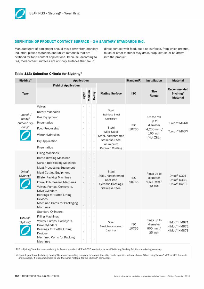
BEARINGS · Slydring® - Wear Ring
256 • TRELLEBORG SEALING SOLUTIONS Latest information available at www.tss.trelleborg.com • Edition December 2015
Table 116: Selection Criteria for Slydring®
Slydring® Application Standard1) Installation Material
Type
Field of Application
Mating Surface ISOSize
Range
Recommended Slydring® MaterialLi
ght
Med
ium
Hea
vy
Turcon® /
Turcite®
Zurcon® Sly-dring®
Valves • • -Steel
Stainless Steel
Aluminium
ISO 10766
Off-the-roll up to
diameter 4,200 mm /
165 inch (Not Z81)
Turcon® MF42)
Turcon® MF62)
Rotary Manifolds • • -
Gas Equipment • • -
Pneumatics • - -
Food Processing • • - Steel Mild Steel
Steel, hardchromed Stainless Steel
Aluminium Ceramic Coating
Water Hydraulics • • -
Dry Application • • -
Pneumatics • • -
Orkot® Slydring®
Filling Machines - • •
Steel Steel, hardchromed
Cast iron Ceramic Coatings Stainless Steel
ISO 10766
Rings up to diameter
1,600 mm /
62 inch
Orkot® C321Orkot® C333Orkot® C410
Bottle Blowing Machines - • •
Carton Box Folding Machines - • •
Meat Processing Equipment - • •
Meat Cutting Equipment - • •
Blister Packing Machines - • •
Form-, Fill-, Sealing Machines - • •Valves, Pumps, Conveyors, Drive Cylinders
- • •
Bearings for Bottle Lifting Devices
- • •
Machined Cams for Packaging Machines
- • •
HiMod® Slydring®
Standard Cylinders - • •
Steel
Steel, hardchromed
Cast iron
ISO 10766
Rings up to diameter
900 mm / 35 inch
HiMod® HM871HiMod® HM872HiMod® HM873
Filling Machines - • •Valves, Pumps, Conveyors, Drive Cylinders
- • •
Bearings for Bottle Lifting Devices
- • •
Machined Cams for Packing Machines
- • •
1) For Slydring® to other standards e.g. to French standard NF E 48-037, contact your local Trelleborg Sealing Solutions marketing company.
2) Consult your local Trelleborg Sealing Solutions marketing company for more information as to specific material choice. When using Turcon® MF4 or MF6 for seals and scrapers, it is recommended to use the same material for the Slydring® component.
DEFInITIOn OF PRODUCT COnTACT SURFACE – 3-A SAnITARy STAnDARDS InC.
Manufacturers of equipment should move away from standard industrial plastic materials and utilize materials that are certified for food contact applications. Because, according to 3-A, food contact surfaces are not only surfaces that are in
direct contact with food, but also surfaces, from which product, fluids or other material may drain, drop, diffuse or be drawn into the product.
FBP_neues_Layout_2015.indb 256 17.10.2016 13:37:51
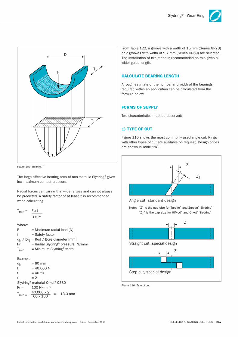
Slydring® - Wear Ring
TRELLEBORG SEALING SOLUTIONS • 257Latest information available at www.tss.trelleborg.com • Edition December 2015
D
FT
T
Figure 109: Bearing T
The large effective bearing area of non-metallic Slydring® gives low maximum contact pressure.
Radial forces can vary within wide ranges and cannot always be predicted. A safety factor of at least 2 is recommended when calculating:
Tmin = F x f ______ D x Pr
Where:F = Maximum radial load [N]f = Safety factordN / DN = Rod / Bore diameter [mm]Pr = Radial Slydring® pressure [N/mm²]Tmin = Minimum Slydring® width
Example:dN = 60 mmF = 40.000 Nt = 40 °Cf = 2Slydring® material Orkot® C380 Pr = 100 N/mm2
Tmin = 40.000 x 2 = 13.3 mm 60 x 100
From Table 122, a groove with a width of 15 mm (Series GR73) or 2 grooves with width of 9.7 mm (Series GR69) are selected. The Installation of two strips is recommended as this gives a wider guide length.
CALCULATE BEARInG LEnGTH
A rough estimate of the number and width of the bearings required within an application can be calculated from the formula below.
FORMS OF SUPPLy
Two characteristics must be observed:
1) TyPE OF CUT
Figure 110 shows the most commonly used angle cut. Rings with other types of cut are available on request. Design codes are shown in Table 118.
Angle cut, standard design
Straight cut, special design
Step cut, special design
Note: “Z” is the gap size for Turcite® and Zurcon® Slydring®
“Z1” is the gap size for HiMod® and Orkot® Slydring®
Z1
Z
Z
Z
Figure 110: Type of cut
FBP_neues_Layout_2015.indb 257 17.10.2016 13:37:52
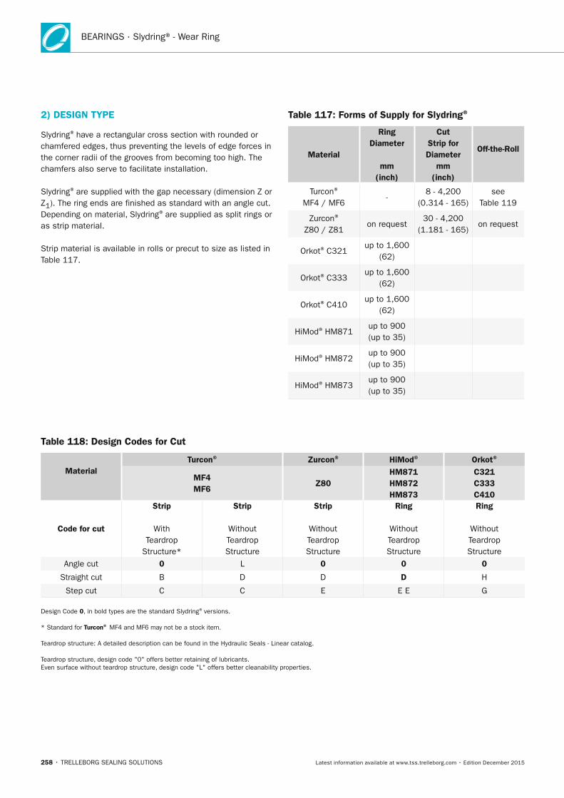
BEARINGS · Slydring® - Wear Ring
258 • TRELLEBORG SEALING SOLUTIONS Latest information available at www.tss.trelleborg.com • Edition December 2015
2) DESIGn TyPE
Slydring® have a rectangular cross section with rounded or chamfered edges, thus preventing the levels of edge forces in the corner radii of the grooves from becoming too high. The chamfers also serve to facilitate installation.
Slydring® are supplied with the gap necessary (dimension Z or Z1). The ring ends are finished as standard with an angle cut.Depending on material, Slydring® are supplied as split rings or as strip material.
Strip material is available in rolls or precut to size as listed in Table 117.
Table 117: Forms of Supply for Slydring®
Material
Ring Diameter
mm (inch)
Cut Strip for Diameter
mm (inch)
Off-the-Roll
Turcon® MF4 / MF6
-8 - 4,200
(0.314 - 165)see
Table 119
Zurcon® Z80 / Z81
on request 30 - 4,200
(1.181 - 165)on request
Orkot® C321 up to 1,600
(62)
Orkot® C333 up to 1,600
(62)
Orkot® C410up to 1,600
(62)
HiMod® HM871up to 900 (up to 35)
HiMod® HM872up to 900 (up to 35)
HiMod® HM873up to 900 (up to 35)
Table 118: Design Codes for Cut
Material
Turcon® Zurcon® HiMod® Orkot®
MF4 MF6
Z80 HM871 HM872 HM873
C321 C333 C410
Code for cut
Strip
With Teardrop
Structure*
Strip
Without Teardrop Structure
Strip
Without Teardrop Structure
Ring
Without Teardrop Structure
Ring
Without Teardrop Structure
Angle cut 0 L 0 0 0
Straight cut B D D D H
Step cut C C E E E G
Design Code 0, in bold types are the standard Slydring® versions.
* Standard for Turcon® MF4 and MF6 may not be a stock item.
Teardrop structure: A detailed description can be found in the Hydraulic Seals - Linear catalog.
Teardrop structure, design code "0" offers better retaining of lubricants. Even surface without teardrop structure, design code "L" offers better cleanability properties.
FBP_neues_Layout_2015.indb 258 17.10.2016 13:37:52
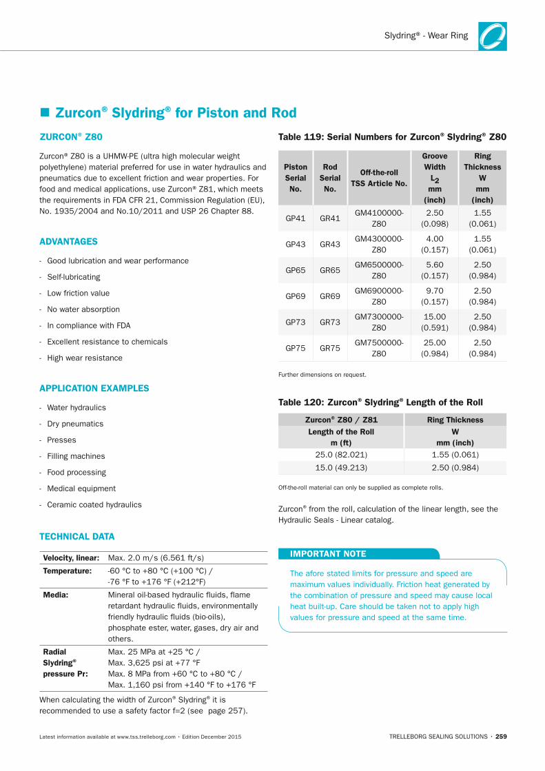
Slydring® - Wear Ring
TRELLEBORG SEALING SOLUTIONS • 259Latest information available at www.tss.trelleborg.com • Edition December 2015
ZURCOn® Z80
Zurcon® Z80 is a UHMW-PE (ultra high molecular weight polyethylene) material preferred for use in water hydraulics and pneumatics due to excellent friction and wear properties. For food and medical applications, use Zurcon® Z81, which meets the requirements in FDA CFR 21, Commission Regulation (EU), No. 1935/2004 and No.10/2011 and USP 26 Chapter 88.
ADVAnTAGES
- Good lubrication and wear performance
- Self-lubricating
- Low friction value
- No water absorption
- In compliance with FDA
- Excellent resistance to chemicals
- High wear resistance
APPLICATIOn ExAMPLES
- Water hydraulics
- Dry pneumatics
- Presses
- Filling machines
- Food processing
- Medical equipment
- Ceramic coated hydraulics
TECHnICAL DATA
Velocity, linear: Max. 2.0 m/s (6.561 ft/s)
Temperature: -60 °C to +80 °C (+100 °C) / -76 °F to +176 °F (+212°F)
Media: Mineral oil-based hydraulic fluids, flame retardant hydraulic fluids, environmentally friendly hydraulic fluids (bio-oils), phosphate ester, water, gases, dry air and others.
Radial Slydring®
pressure Pr:
Max. 25 MPa at +25 °C / Max. 3,625 psi at +77 °F Max. 8 MPa from +60 °C to +80 °C / Max. 1,160 psi from +140 °F to +176 °F
When calculating the width of Zurcon® Slydring® it is recommended to use a safety factor f=2 (see page 257).
Table 119: Serial numbers for Zurcon® Slydring® Z80
Piston Serial no.
Rod Serial no.
Off-the-roll TSS Article no.
Groove Width
L2mm
(inch)
Ring Thickness
Wmm
(inch)
GP41 GR41 GM4100000-
Z80 2.50
(0.098)1.55
(0.061)
GP43 GR43 GM4300000-
Z80 4.00
(0.157)1.55
(0.061)
GP65 GR65 GM6500000-
Z80 5.60
(0.157)2.50
(0.984)
GP69 GR69 GM6900000-
Z80 9.70
(0.157)2.50
(0.984)
GP73 GR73 GM7300000-
Z80 15.00
(0.591)2.50
(0.984)
GP75 GR75 GM7500000-
Z80 25.00
(0.984)2.50
(0.984)
Further dimensions on request.
Table 120: Zurcon® Slydring® Length of the Roll
Zurcon® Z80 / Z81 Ring Thickness Length of the Roll
m (ft)W
mm (inch)25.0 (82.021) 1.55 (0.061)
15.0 (49.213) 2.50 (0.984)
Off-the-roll material can only be supplied as complete rolls.
Zurcon® from the roll, calculation of the linear length, see the Hydraulic Seals - Linear catalog.
IMPORTAnT nOTE
The afore stated limits for pressure and speed are maximum values individually. Friction heat generated by the combination of pressure and speed may cause local heat built-up. Care should be taken not to apply high values for pressure and speed at the same time.
� Zurcon® Slydring® for Piston and Rod
FBP_neues_Layout_2015.indb 259 17.10.2016 13:37:53
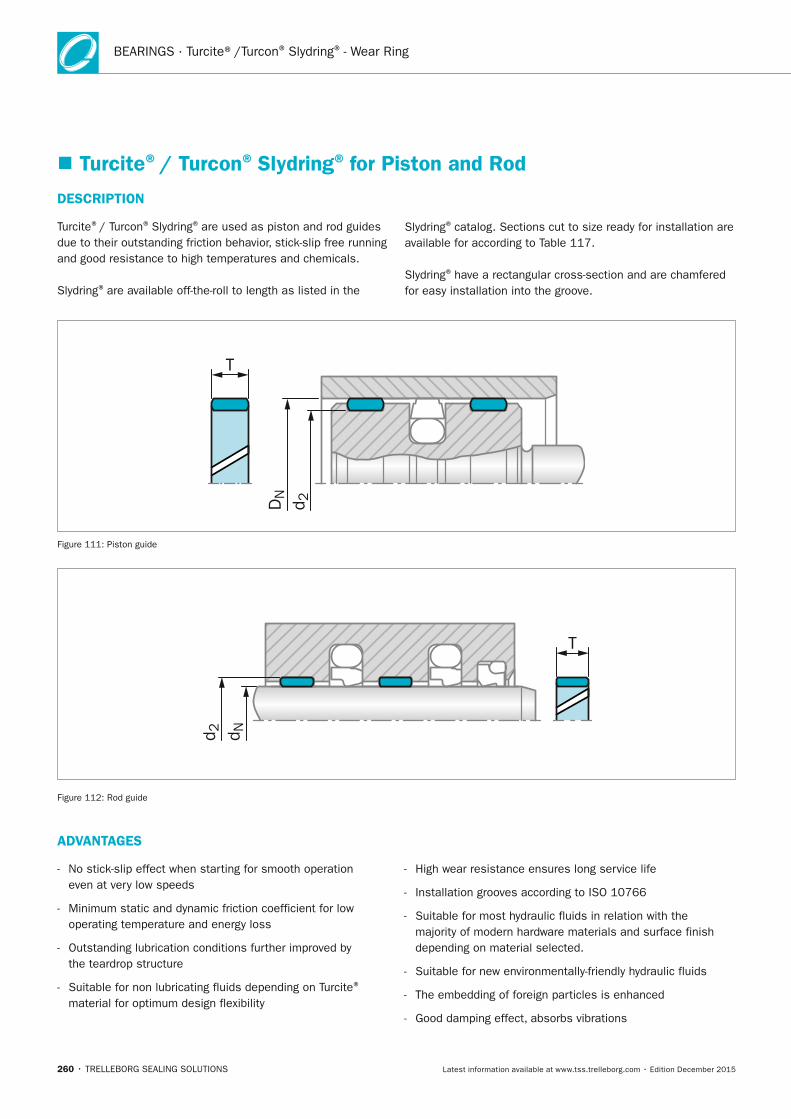
260 • TRELLEBORG SEALING SOLUTIONS Latest information available at www.tss.trelleborg.com • Edition December 2015
BEARINGS · Turcite®/Turcon® Slydring® - Wear Ring
DESCRIPTIOn
Turcite®/ Turcon® Slydring® are used as piston and rod guides due to their outstanding friction behavior, stick-slip free running and good resistance to high temperatures and chemicals.
Slydring® are available off-the-roll to length as listed in the
� Turcite®/ Turcon® Slydring® for Piston and Rod
ADVAnTAGES
- No stick-slip effect when starting for smooth operation even at very low speeds
- Minimum static and dynamic friction coefficient for low operating temperature and energy loss
- Outstanding lubrication conditions further improved by the teardrop structure
- Suitable for non lubricating fluids depending on Turcite®
material for optimum design flexibility
- High wear resistance ensures long service life
- Installation grooves according to ISO 10766
- Suitable for most hydraulic fluids in relation with the majority of modern hardware materials and surface finish depending on material selected.
- Suitable for new environmentally-friendly hydraulic fluids
- The embedding of foreign particles is enhanced
- Good damping effect, absorbs vibrations
T
DN
d 2
Figure 111: Piston guide
T
d 2 d N
Figure 112: Rod guide
Slydring® catalog. Sections cut to size ready for installation are available for according to Table 117.
Slydring® have a rectangular cross-section and are chamfered for easy installation into the groove.
FBP_neues_Layout_2015.indb 260 17.10.2016 13:37:53
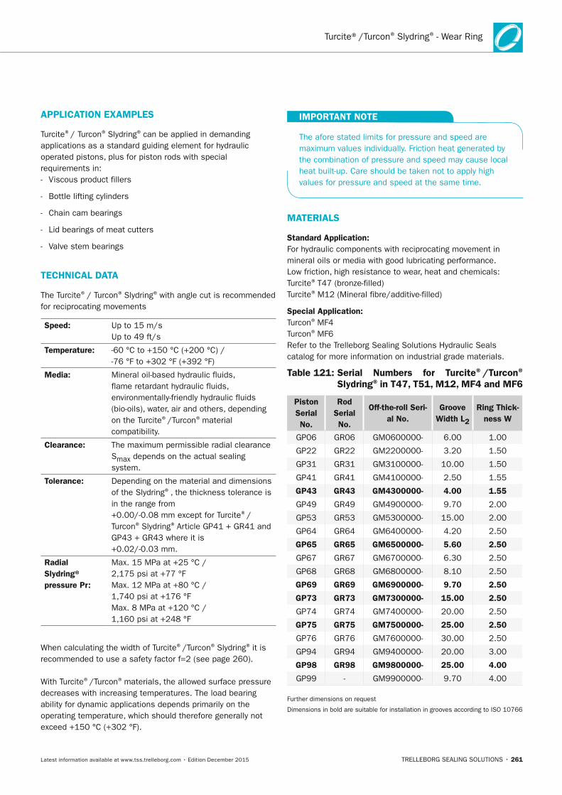
TRELLEBORG SEALING SOLUTIONS • 261Latest information available at www.tss.trelleborg.com • Edition December 2015
Turcite®/Turcon® Slydring® - Wear Ring
APPLICATIOn ExAMPLES
Turcite®/ Turcon® Slydring® can be applied in demanding applications as a standard guiding element for hydraulic operated pistons, plus for piston rods with special requirements in: - Viscous product fillers
- Bottle lifting cylinders
- Chain cam bearings
- Lid bearings of meat cutters
- Valve stem bearings
TECHnICAL DATA
The Turcite® / Turcon® Slydring® with angle cut is recommended for reciprocating movements
Speed: Up to 15 m/s Up to 49 ft/s
Temperature: -60 °C to +150 °C (+200 °C) / -76 °F to +302 °F (+392 °F)
Media: Mineral oil-based hydraulic fluids, flame retardant hydraulic fluids, environmentally-friendly hydraulic fluids (bio-oils), water, air and others, depending on the Turcite®/Turcon® material compatibility.
Clearance: The maximum permissible radial clearance Smax depends on the actual sealing system.
Tolerance: Depending on the material and dimensions of the Slydring®, the thickness tolerance is in the range from +0.00/-0.08 mm except for Turcite®/Turcon® Slydring® Article GP41 + GR41 and GP43 + GR43 where it is +0.02/-0.03 mm.
Radial Slydring® pressure Pr:
Max. 15 MPa at +25 °C / 2,175 psi at +77 °F Max. 12 MPa at +80 °C / 1,740 psi at +176 °F Max. 8 MPa at +120 °C / 1,160 psi at +248 °F
When calculating the width of Turcite®/Turcon® Slydring® it is recommended to use a safety factor f=2 (see page 260).
With Turcite®/Turcon® materials, the allowed surface pressure decreases with increasing temperatures. The load bearing ability for dynamic applications depends primarily on the operating temperature, which should therefore generally not exceed +150 °C (+302 °F).
IMPORTAnT nOTE
The afore stated limits for pressure and speed are maximum values individually. Friction heat generated by the combination of pressure and speed may cause local heat built-up. Care should be taken not to apply high values for pressure and speed at the same time.
MATERIALS
Standard Application:For hydraulic components with reciprocating movement in mineral oils or media with good lubricating performance. Low friction, high resistance to wear, heat and chemicals: Turcite® T47 (bronze-filled)Turcite® M12 (Mineral fibre/additive-filled)
Special Application:Turcon® MF4Turcon® MF6Refer to the Trelleborg Sealing Solutions Hydraulic Seals catalog for more information on industrial grade materials.
Table 121: Serial numbers for Turcite®/Turcon® Slydring® in T47, T51, M12, MF4 and MF6
Piston Serial no.
Rod Serial no.
Off-the-roll Seri-al no.
Groove Width L2
Ring Thick-ness W
GP06 GR06 GM0600000- 6.00 1.00
GP22 GR22 GM2200000- 3.20 1.50
GP31 GR31 GM3100000- 10.00 1.50
GP41 GR41 GM4100000- 2.50 1.55
GP43 GR43 GM4300000- 4.00 1.55
GP49 GR49 GM4900000- 9.70 2.00
GP53 GR53 GM5300000- 15.00 2.00
GP64 GR64 GM6400000- 4.20 2.50
GP65 GR65 GM6500000- 5.60 2.50
GP67 GR67 GM6700000- 6.30 2.50
GP68 GR68 GM6800000- 8.10 2.50
GP69 GR69 GM6900000- 9.70 2.50
GP73 GR73 GM7300000- 15.00 2.50
GP74 GR74 GM7400000- 20.00 2.50
GP75 GR75 GM7500000- 25.00 2.50
GP76 GR76 GM7600000- 30.00 2.50
GP94 GR94 GM9400000- 20.00 3.00
GP98 GR98 GM9800000- 25.00 4.00
GP99 - GM9900000- 9.70 4.00
Further dimensions on request
Dimensions in bold are suitable for installation in grooves according to ISO 10766
FBP_neues_Layout_2015.indb 261 17.10.2016 13:37:54
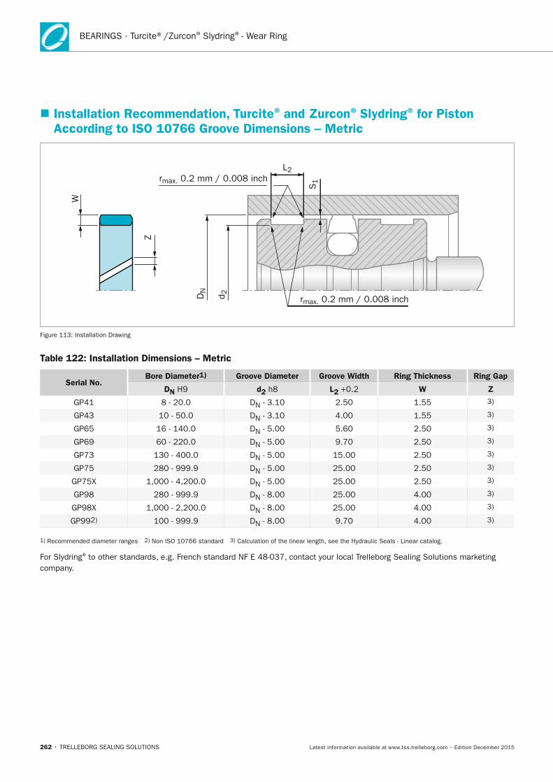
262 • TRELLEBORG SEALING SOLUTIONS Latest information available at www.tss.trelleborg.com • Edition December 2015
BEARINGS · Turcite®/Zurcon® Slydring® - Wear Ring
� Installation Recommendation, Turcite® and Zurcon® Slydring® for Piston According to ISO 10766 Groove Dimensions – Metric
L2
S1rmax. 0.2 mm / 0.008 inch
rmax. 0.2 mm / 0.008 inchDN
d 2
W
Z
Figure 113: Installation Drawing
Table 122: Installation Dimensions – Metric
Serial no.Bore Diameter1) Groove Diameter Groove Width Ring Thickness Ring Gap
Dn H9 d2 h8 L2 +0.2 W Z
GP41 8 - 20.0 DN - 3.10 2.50 1.55 3)
GP43 10 - 50.0 DN - 3.10 4.00 1.55 3)
GP65 16 - 140.0 DN - 5.00 5.60 2.50 3)
GP69 60 - 220.0 DN - 5.00 9.70 2.50 3)
GP73 130 - 400.0 DN - 5.00 15.00 2.50 3)
GP75 280 - 999.9 DN - 5.00 25.00 2.50 3)
GP75X 1,000 - 4,200.0 DN - 5.00 25.00 2.50 3)
GP98 280 - 999.9 DN - 8.00 25.00 4.00 3)
GP98X 1,000 - 2,200.0 DN - 8.00 25.00 4.00 3)
GP992) 100 - 999.9 DN - 8.00 9.70 4.00 3)
1) Recommended diameter ranges 2) Non ISO 10766 standard 3) Calculation of the linear length, see the Hydraulic Seals - Linear catalog.
For Slydring® to other standards, e.g. French standard NF E 48-037, contact your local Trelleborg Sealing Solutions marketing company.
FBP_neues_Layout_2015.indb 262 17.10.2016 13:37:54
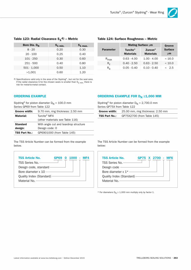
TRELLEBORG SEALING SOLUTIONS • 263Latest information available at www.tss.trelleborg.com • Edition December 2015
Turcite®/Zurcon® Slydring® - Wear Ring
ORDERInG ExAMPLE
Slydring® for piston diameter DN = 100.0 mm Series GP69 from Table 122
Groove width: 9.70 mm, ring thickness: 2.50 mm
Material: Turcite® MF4 (other materials see Table 116)
Standard design:
With angle cut and teardrop structure Design code: 0
TSS Part no.: GP6901000 (from Table 145)
The TSS Article Number can be formed from the example below.
Material No.
TSS Series No.
TSS Article No.
Bore diameter x 10Quality Index (Standard)
Design code, standard
MF4GP69 -0 1000
ORDERInG ExAMPLE FOR Dn ≥1,000 MM
Slydring® for piston diameter DN = 2,700.0 mm Series GP75X from Table 122
Groove width: 25.00 mm, ring thickness: 2.50 mm
TSS Part no.: GP75X2700 (from Table 145)
The TSS Article Number can be formed from the example below:
Material No.
TSS Series No.
TSS Article No.
Bore diameter x 1*Quality Index (Standard)
Design code
MF6GP75 -X 2700
* For diameters DN ≥ 1,000 mm multiply only by factor 1.
Table 123: Radial Clearance S14) – Metric
Bore Dia. Dn S1 min. S1 max.8 - 20 0.20 0.30
20 - 100 0.25 0.40
101 - 250 0.30 0.60
251 - 500 0.40 0.80
501 - 1,000 0.50 1.10
>1,001 0.60 1.20
4) Specifications valid only in the area of the Slydring®, but not for the seal area. If the radial clearance S for the chosen seals is smaller than S1 min. there is risk for metal-to-metal contact.
Table 124: Surface Roughness – Metric
Parameter
Mating Surface μm Groove Surface
μmTurcite®
MaterialsZurcon®
Materials
Rmax 0.63 - 4.00 1.00 - 4.00 < 16.0
Rz 0.40 - 2.50 0.63 - 2.50 < 10.0
Ra 0.05 - 0.40 0.10 - 0.40 < 2.5
FBP_neues_Layout_2015.indb 263 17.10.2016 13:37:55
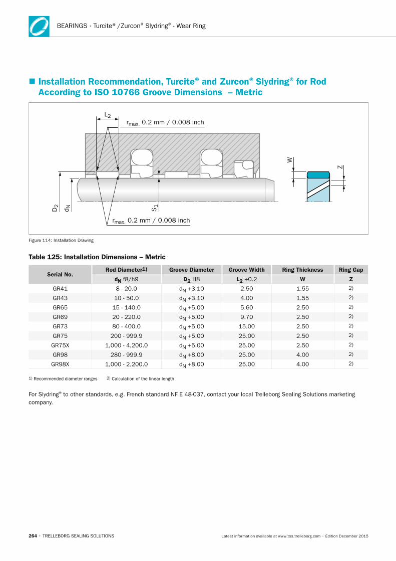
264 • TRELLEBORG SEALING SOLUTIONS Latest information available at www.tss.trelleborg.com • Edition December 2015
BEARINGS · Turcite®/Zurcon® Slydring® - Wear Ring
� Installation Recommendation, Turcite® and Zurcon® Slydring® for Rod According to ISO 10766 Groove Dimensions – Metric
rmax. 0.2 mm / 0.008 inch
rmax. 0.2 mm / 0.008 inch
L2
S1
D2
d N
W
Z
Figure 114: Installation Drawing
Table 125: Installation Dimensions – Metric
Serial no.Rod Diameter1) Groove Diameter Groove Width Ring Thickness Ring Gap
dn f8/h9 D2 H8 L2 +0.2 W Z
GR41 8 - 20.0 dN +3.10 2.50 1.55 2)
GR43 10 - 50.0 dN +3.10 4.00 1.55 2)
GR65 15 - 140.0 dN +5.00 5.60 2.50 2)
GR69 20 - 220.0 dN +5.00 9.70 2.50 2)
GR73 80 - 400.0 dN +5.00 15.00 2.50 2)
GR75 200 - 999.9 dN +5.00 25.00 2.50 2)
GR75X 1,000 - 4,200.0 dN +5.00 25.00 2.50 2)
GR98 280 - 999.9 dN +8.00 25.00 4.00 2)
GR98X 1,000 - 2,200.0 dN +8.00 25.00 4.00 2)
1) Recommended diameter ranges 2) Calculation of the linear length
For Slydring® to other standards, e.g. French standard NF E 48-037, contact your local Trelleborg Sealing Solutions marketing company.
FBP_neues_Layout_2015.indb 264 17.10.2016 13:37:55

TRELLEBORG SEALING SOLUTIONS • 265Latest information available at www.tss.trelleborg.com • Edition December 2015
Turcite®/Zurcon® Slydring® - Wear Ring
ORDERInG ExAMPLE
Slydring® for rod diameter dN = 63.0 mm Series GR65 from Table 125
Groove width: 5.60 mm, ring thickness: 2.50 mm
Material: Turcite® MF4 (other materials see Table 116)
Standard design:
With angle cut and teardrop structure Design code: 0
TSS Part no.: GR6500630 (from Table 146)
The TSS Article Number can be formed from the example below:
Material No.
TSS Series No.
TSS Article No.
Rod diameter x 10Quality Index (Standard)
Design code, standard
GR65 -0 0630 MF4
ORDERInG ExAMPLE FOR Dn ≥1,000 MM
Slydring® for rod diameter dN = 2,600.0 mm Series GR75X from Table 125
Groove width: 25.00 mm, ring thickness: 2.50 mm
TSS Part no.: GR75X2600 (from Table 146)
The TSS Article Number can be formed from the example below:
Material No.
TSS Series No.
TSS Article No.
Rod diameter x 1*Quality Index (Standard)
Design code
MF6GR75 -X 2600
* For diameters dN ≥ 1,000 mm multiply only by factor 1.
Table 126: Radial Clearance S13) – Metric
Rod Dia. dn S1 min. S1 max.8 - 20 0.20 0.30
20 - 100 0.25 0.40
101 - 250 0.30 0.60
251 - 500 0.40 0.80
501 - 1,000 0.50 1.10
>1,001 0.60 1.20
3) Specifications valid only in the area of the Slydring®, but not for the seal area. If the radial clearance S for the chosen seals is smaller than S1 min. there is risk for metal-to-metal contact.
Table 127: Surface Roughness
Parameter
Mating Surface μmGroove
Surface μmTurcite®
MaterialsZurcon®
Materials
Rmax 0.63 - 4.00 1.00 - 4.00 < 16.0
Rz 0.40 - 2.50 0.63 - 2.50 < 10.0
Ra 0.05 - 0.40 0.10 - 0.40 < 2.5
FBP_neues_Layout_2015.indb 265 17.10.2016 13:37:56
266 • TRELLEBORG SEALING SOLUTIONS Latest information available at www.tss.trelleborg.com • Edition December 2015
BEARINGS · HiMod® Slydring® - Wear Ring
DESCRIPTIOn
HiMod® Slydring® are made of a special, modified thermoplastic material and can be used in hydraulic cylinders for medium to high loads. Three different grades of material are available:
HiMod® HM871: A special glass fiber reinforced polyacetal
HiMod® HM872: A special glass fiber reinforced heat-stabilized polyamid with PTFE filler
HiMod® HM873: A special glass fiber reinforced heat-stabilized polyamid
HiMod® Slydring® in material HM871, HM872 and HM873 are injection molded to finish parts (mold necessary), or machined from semi-finished tubes. A wide range of standard sizes are available (see Slydring® catalog).
APPLICATIOn ExAMPLES
HiMod® Slydring® (HM871, HM872, HM873) is generally utilized in a wide range of hydraulic equipment such as:
- Standard hydraulic cylinder, medium range
- Food, beverage and pharmaceutical equipment
MATERIALS
HIMOD® HM871
HiMod® HM871 is a polyacetal (POM) based material with glass fibers.
ADVAnTAGES
- Favorable price/performance ratio
- High compressive strength
- Easy installation on pistons and glands (gland bore > 40 mm / 1.575 inch)
- High wear resistance
- Water absorption 0.2 %
- High stiffness
TECHnICAL DATA
Velocity, reciprocating:
Max. 0.8 m/s / 2.625 fps
Temperature: -40 °C to +110 °C / -40 °F to +230 °F
Radial Slydring®
Pressure Pr:
Max. 40 MPa at +25 °C / 5,800 psi at +77 °F Max. 25 MPa > +60 °C / 3,625 psi > +140 °F
When calculating the width of HiMod® Slydring® it is recommended to use a safety factor f=2 (see page 260).
IMPORTAnT nOTE
The afore stated limits for pressure and speed are maximum values individually. Friction heat generated by the combination of pressure and speed may cause local heat built-up. Care should be taken not to apply high values for pressure and speed at the same time.
� HiMod® Slydring® for Piston and Rod
FBP_neues_Layout_2015.indb 266 17.10.2016 13:37:56
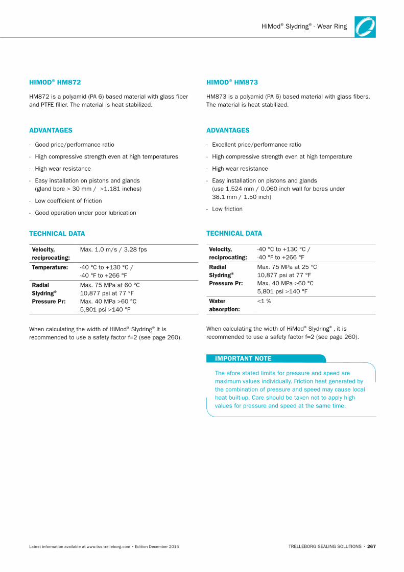
TRELLEBORG SEALING SOLUTIONS • 267Latest information available at www.tss.trelleborg.com • Edition December 2015
HiMod® Slydring® - Wear Ring
HIMOD® HM872
HM872 is a polyamid (PA 6) based material with glass fiber and PTFE filler. The material is heat stabilized.
ADVAnTAGES
- Good price/performance ratio
- High compressive strength even at high temperatures
- High wear resistance
- Easy installation on pistons and glands (gland bore > 30 mm / >1.181 inches)
- Low coefficient of friction
- Good operation under poor lubrication
TECHnICAL DATA
Velocity, reciprocating:
Max. 1.0 m/s / 3.28 fps
Temperature: -40 °C to +130 °C / -40 °F to +266 °F
Radial Slydring®
Pressure Pr:
Max. 75 MPa at 60 °C 10,877 psi at 77 °F Max. 40 MPa >60 °C 5,801 psi >140 °F
When calculating the width of HiMod® Slydring® it is recommended to use a safety factor f=2 (see page 260).
HIMOD® HM873
HM873 is a polyamid (PA 6) based material with glass fibers. The material is heat stabilized.
ADVAnTAGES
- Excellent price/performance ratio
- High compressive strength even at high temperature
- High wear resistance
- Easy installation on pistons and glands (use 1.524 mm / 0.060 inch wall for bores under 38.1 mm / 1.50 inch)
- Low friction
TECHnICAL DATA
Velocity, reciprocating:
-40 °C to +130 °C / -40 °F to +266 °F
Radial Slydring® Pressure Pr:
Max. 75 MPa at 25 °C 10,877 psi at 77 °F Max. 40 MPa >60 °C 5,801 psi >140 °F
Water absorption:
<1 %
When calculating the width of HiMod® Slydring®, it is recommended to use a safety factor f=2 (see page 260).
IMPORTAnT nOTE
The afore stated limits for pressure and speed are maximum values individually. Friction heat generated by the combination of pressure and speed may cause local heat built-up. Care should be taken not to apply high values for pressure and speed at the same time.
FBP_neues_Layout_2015.indb 267 17.10.2016 13:37:56
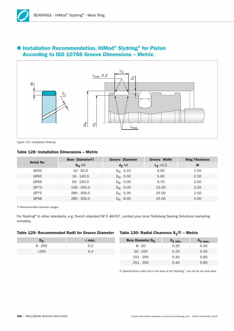
268 • TRELLEBORG SEALING SOLUTIONS Latest information available at www.tss.trelleborg.com • Edition December 2015
BEARINGS · HiMod® Slydring® - Wear Ring
� Installation Recommendation, HiMod® Slydring® for Piston According to ISO 10766 Groove Dimensions – Metric
L2
Z1
S1rmax. 0.2
rmax.
DN
d 2
W
Figure 115: Installation Drawing
Table 128: Installation Dimensions – Metric
Serial no. Bore Diameter1) Groove Diameter Groove Width Ring Thickness
Dn H9 d2 h8 L2 +0.2 W
GP43 10 - 50.0 DN - 3.10 4.00 1.55
GP65 16 - 140.0 DN - 5.00 5.60 2.50
GP69 60 - 220.0 DN - 5.00 9.70 2.50
GP73 130 - 300.0 DN - 5.00 15.00 2.50
GP75 280 - 300.0 DN - 5.00 25.00 2.50
GP98 280 - 300.0 DN - 8.00 25.00 4.00
1) Recommended diameter ranges
For Slydring® to other standards, e.g. French standard NF E 48-037, contact your local Trelleborg Sealing Solutions marketing company.
Table 129: Recommended Radii for Groove Diameter
Dn r max.
8 - 250 0.2
>250 0.4
Table 130: Radial Clearence S12) – Metric
Bore Diameter Dn S1 min. S1 max.8 - 20 0.20 0.30
20 - 100 0.25 0.40
101 - 250 0.30 0.60
251 - 300 0.40 0.80
2) Specifications valid only in the area of the Slydring®, but not for the seal area.
FBP_neues_Layout_2015.indb 268 17.10.2016 13:37:57

TRELLEBORG SEALING SOLUTIONS • 269Latest information available at www.tss.trelleborg.com • Edition December 2015
HiMod® Slydring® - Wear Ring
Table 131: Recommended Gap – Metric
Dn Ring Gap Z1
10 - 44 1.5 - 3.0
45 - 149 2.0 - 3.5
>150 3.0 - 5.0
ORDERInG ExAMPLESlydring® for bore diameter DN = 100.0 mm Series GP69 from Table 128
Groove width: 9.70 mm, ring thickness: 2.50 mm
Material: HiMod® HM871 (other materials see Table 116)
Standard design:
With angle cut Design code: 0
TSS Article no.:
GP6901000-HM061 (see Slydring® catalog, page 32)
note:HM872 and HM873 material can be ordered by replacing the HM871 material code in the TSS Article Number.
Table 132: Surface Roughness – Metric
ParameterMating Surface μm Groove
Surface μm HiMod® Materials
Rmax 1.00 - 4.00 < 16.0
Rz DIN 0.63 - 2.50 < 10.0
Ra 0.10 - 0.40 < 2.5
Material No.
TSS Series No.
TSS Article No.
Bore diameter x 10Quality Index (Standard)
Design code, standard
HM871GP69 -0 1000
FBP_neues_Layout_2015.indb 269 17.10.2016 13:37:57
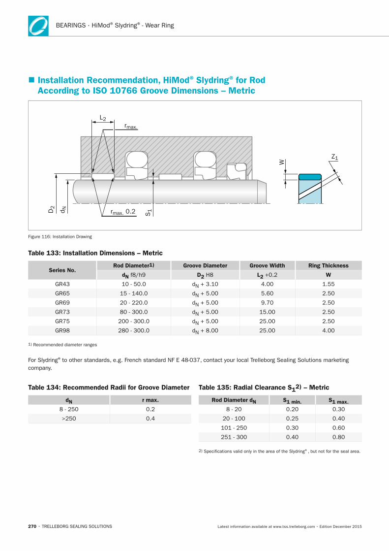
270 • TRELLEBORG SEALING SOLUTIONS Latest information available at www.tss.trelleborg.com • Edition December 2015
BEARINGS · HiMod® Slydring® - Wear Ring
� Installation Recommendation, HiMod® Slydring® for Rod According to ISO 10766 Groove Dimensions – Metric
Z1
rmax.
L2
S1rmax. 0.2D
2
d N
W
Figure 116: Installation Drawing
Table 133: Installation Dimensions – Metric
Series no. Rod Diameter1) Groove Diameter Groove Width Ring Thickness
dn f8/h9 D2 H8 L2 +0.2 W
GR43 10 - 50.0 dN + 3.10 4.00 1.55
GR65 15 - 140.0 dN + 5.00 5.60 2.50
GR69 20 - 220.0 dN + 5.00 9.70 2.50
GR73 80 - 300.0 dN + 5.00 15.00 2.50
GR75 200 - 300.0 dN + 5.00 25.00 2.50
GR98 280 - 300.0 dN + 8.00 25.00 4.00
1) Recommended diameter ranges
For Slydring® to other standards, e.g. French standard NF E 48-037, contact your local Trelleborg Sealing Solutions marketing company.
Table 134: Recommended Radii for Groove Diameter
dn r max.
8 - 250 0.2
>250 0.4
Table 135: Radial Clearance S12) – Metric
Rod Diameter dn S1 min. S1 max. 8 - 20 0.20 0.30
20 - 100 0.25 0.40
101 - 250 0.30 0.60
251 - 300 0.40 0.80
2) Specifications valid only in the area of the Slydring®, but not for the seal area.
FBP_neues_Layout_2015.indb 270 17.10.2016 13:37:58
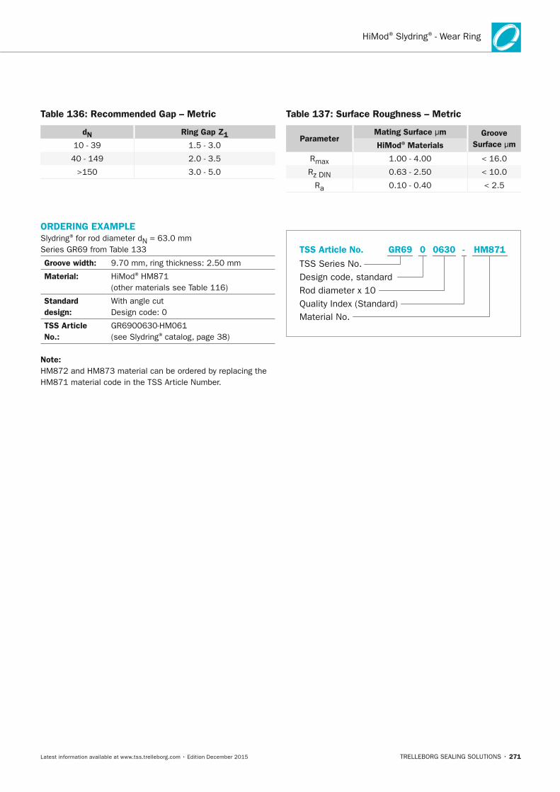
TRELLEBORG SEALING SOLUTIONS • 271Latest information available at www.tss.trelleborg.com • Edition December 2015
HiMod® Slydring® - Wear Ring
Table 136: Recommended Gap – Metric
dn Ring Gap Z1
10 - 39 1.5 - 3.0
40 - 149 2.0 - 3.5
>150 3.0 - 5.0
ORDERInG ExAMPLESlydring® for rod diameter dN = 63.0 mmSeries GR69 from Table 133
Groove width: 9.70 mm, ring thickness: 2.50 mm
Material: HiMod® HM871 (other materials see Table 116)
Standard design:
With angle cut Design code: 0
TSS Article no.:
GR6900630-HM061 (see Slydring® catalog, page 38)
note:HM872 and HM873 material can be ordered by replacing the HM871 material code in the TSS Article Number.
Table 137: Surface Roughness – Metric
Parameter Mating Surface μm Groove
Surface μm HiMod® Materials
Rmax 1.00 - 4.00 < 16.0
Rz DIN 0.63 - 2.50 < 10.0
Ra 0.10 - 0.40 < 2.5
Material No.
TSS Series No.
TSS Article No.
Rod diameter x 10Quality Index (Standard)
Design code, standard
HM871GR69 -0 0630
FBP_neues_Layout_2015.indb 271 17.10.2016 13:37:58
272 • TRELLEBORG SEALING SOLUTIONS Latest information available at www.tss.trelleborg.com • Edition December 2015
BEARINGS · Orkot® Slydring® - Wear Ring
DESCRIPTIOn
Orkot® Slydring®, made from fabric-reinforced composite materials, is typically used in hydraulic cylinders exposed to high loads, e.g. mobile hydraulics and presses. The high compressive strength, good sliding behavior and the exceptional wear resistance properties ensure a long service life.
Slydring® of Orkot® fabric composite materials is produced as standard preformed to the intended diameter and ready-to-fit. It is manufactured with an angle cut and already has the necessary gap "Z1".
ADVAnTAGES
- Dimensionally stable and vibration absorbing
- Even distribution of high radial forces
- Good sliding and dry running properties
- High wear resistance
- Good wiping effect
- Long service life.
APPLICATIOn ExAMPLES
Orkot® Slydring® is widely used as a bearing element for heavy duty hydraulic equipment.
TECHnICAL DATA
Velocity: Up to 1 m/s / 3.2 fps with reciprocating movements
Temperature: - 60 °C to + 120 °C / -76 °F to +248 °F
Pr under dynamicconditions(C321, C333, C410):
max. 100 N/mm2 at +25 °C / +77 °F max. 50 N/mm2 > +60 °C / +140 °F
Ultimate compressivestrength
(C321, C333): max. > 300 N/ mm2
(C410): max. 260 N/mm2
When calculating the width of Orkot® Slydring®, it is recommended to use a safety factor f=2 (see page 260).
IMPORTAnT nOTE
The afore stated limits for pressure and speed are maximum values individually. Friction heat generated by the combination of pressure and speed may cause local heat built-up. Care should be taken not to apply high values for pressure and speed at the same time.
MATERIALS
ORKOT® C321 AnD ORKOT® C333
Orkot® C321 and C333 are manufactured from medium weave fabrics with excellent mechanical strength. They are dimensional stable when immersed in water, acids and chemical solutions.
ORKOT® C410
Orkot® C410 comprises a thermosetting resin coated onto medium weave fabrics incorporating a mixture of lubricants. The material possesses excellent dimensional stability in water and oil and demonstrates very good friction and wear properties.
� Orkot® Slydring® for Piston and Rod
FBP_neues_Layout_2015.indb 272 17.10.2016 13:37:58
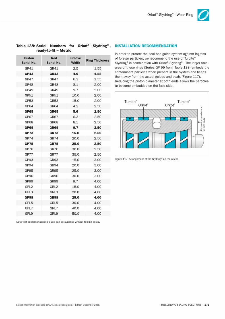
TRELLEBORG SEALING SOLUTIONS • 273Latest information available at www.tss.trelleborg.com • Edition December 2015
Orkot® Slydring® - Wear Ring
Table 138: Serial numbers for Orkot® Slydring®, ready-to-fit – Metric
Piston Serial no.
Rod Serial no.
Groove Width
Ring Thickness
GP41 GR41 2.5 1.55
GP43 GR43 4.0 1.55
GP47 GR47 6.3 1.55
GP48 GR48 8.1 2.00
GP49 GR49 9.7 2.00
GP51 GR51 10.0 2.00
GP53 GR53 15.0 2.00
GP64 GR64 4.2 2.50
GP65 GR65 5.6 2.50
GP67 GR67 6.3 2.50
GP68 GR68 8.1 2.50
GP69 GR69 9.7 2.50
GP73 GR73 15.0 2.50
GP74 GR74 20.0 2.50
GP75 GR75 25.0 2.50
GP76 GR76 30.0 2.50
GP77 GR77 35.0 2.50
GP93 GR93 15.0 3.00
GP94 GR94 20.0 3.00
GP95 GR95 25.0 3.00
GP96 GR96 30.0 3.00
GP99 GR99 9.7 4.00
GPL2 GRL2 15.0 4.00
GPL3 GRL3 20.0 4.00
GP98 GR98 25.0 4.00
GPL5 GRL5 30.0 4.00
GPL7 GRL7 40.0 4.00
GPL9 GRL9 50.0 4.00
Note that customer specific sizes can be supplied without tooling costs.
InSTALLATIOn RECOMMEnDATIOn
In order to protect the seal and guide system against ingress of foreign particles, we recommend the use of Turcite®
Slydring® in combination with Orkot® Slydring®. The larger face area of these rings (Series GP 99 from Table 138) embeds the contaminant particles when present in the system and keeps them away from the actual guides and seals (Figure 117). Reducing the piston diameter at both ends allows the particles to become embedded on the face side.
Red
uced
pis
ton
diam
eter
at b
oth
ends
Orkot®Orkot®Turcite®Turcite®
Figure 117: Arrangement of the Slydring® on the piston
FBP_neues_Layout_2015.indb 273 17.10.2016 13:37:59
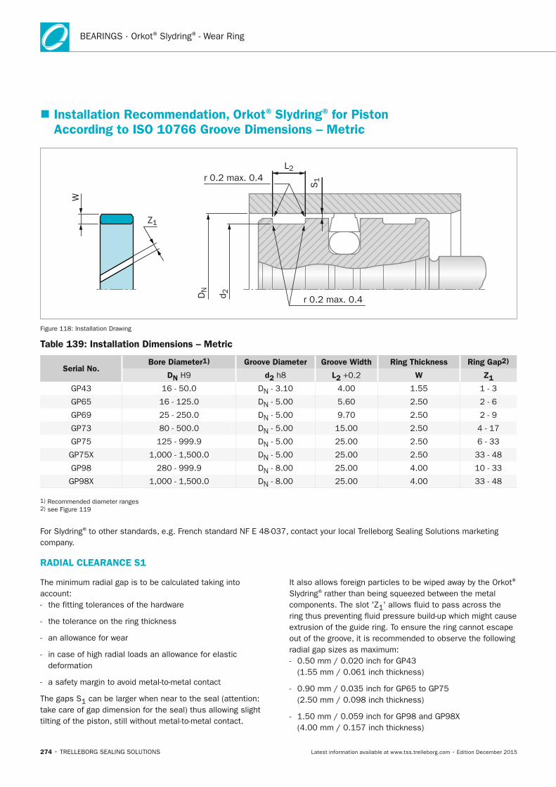
274 • TRELLEBORG SEALING SOLUTIONS Latest information available at www.tss.trelleborg.com • Edition December 2015
BEARINGS · Orkot® Slydring® - Wear Ring
Z1
L2
S1r 0.2 max. 0.4
r 0.2 max. 0.4DN
d 2
W
Figure 118: Installation Drawing
Table 139: Installation Dimensions – Metric
Serial no. Bore Diameter1) Groove Diameter Groove Width Ring Thickness Ring Gap2)
Dn H9 d2 h8 L2 +0.2 W Z1
GP43 16 - 50.0 DN - 3.10 4.00 1.55 1 - 3
GP65 16 - 125.0 DN - 5.00 5.60 2.50 2 - 6
GP69 25 - 250.0 DN - 5.00 9.70 2.50 2 - 9
GP73 80 - 500.0 DN - 5.00 15.00 2.50 4 - 17
GP75 125 - 999.9 DN - 5.00 25.00 2.50 6 - 33
GP75X 1,000 - 1,500.0 DN - 5.00 25.00 2.50 33 - 48
GP98 280 - 999.9 DN - 8.00 25.00 4.00 10 - 33
GP98X 1,000 - 1,500.0 DN - 8.00 25.00 4.00 33 - 48
1) Recommended diameter ranges 2) see Figure 119
For Slydring® to other standards, e.g. French standard NF E 48-037, contact your local Trelleborg Sealing Solutions marketing company.
� Installation Recommendation, Orkot® Slydring® for Piston According to ISO 10766 Groove Dimensions – Metric
RADIAL CLEARAnCE S1
The minimum radial gap is to be calculated taking into account: - the fitting tolerances of the hardware
- the tolerance on the ring thickness
- an allowance for wear
- in case of high radial loads an allowance for elastic deformation
- a safety margin to avoid metal-to-metal contact
The gaps S1 can be larger when near to the seal (attention: take care of gap dimension for the seal) thus allowing slight tilting of the piston, still without metal-to-metal contact.
It also allows foreign particles to be wiped away by the Orkot®
Slydring® rather than being squeezed between the metal components. The slot 'Z1' allows fluid to pass across the ring thus preventing fluid pressure build-up which might cause extrusion of the guide ring. To ensure the ring cannot escape out of the groove, it is recommended to observe the following radial gap sizes as maximum: - 0.50 mm / 0.020 inch for GP43
(1.55 mm / 0.061 inch thickness)
- 0.90 mm / 0.035 inch for GP65 to GP75 (2.50 mm / 0.098 inch thickness)
- 1.50 mm / 0.059 inch for GP98 and GP98X (4.00 mm / 0.157 inch thickness)
FBP_neues_Layout_2015.indb 274 17.10.2016 13:37:59
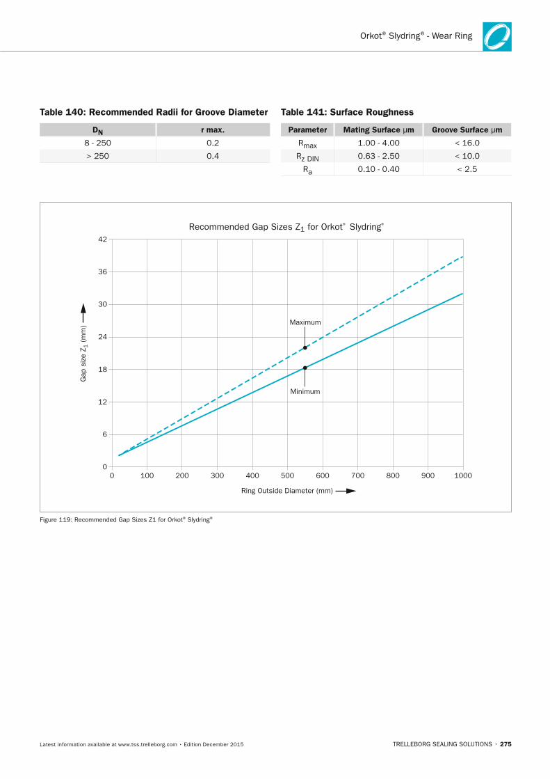
TRELLEBORG SEALING SOLUTIONS • 275Latest information available at www.tss.trelleborg.com • Edition December 2015
Orkot® Slydring® - Wear Ring
Table 140: Recommended Radii for Groove Diameter
Dn r max.
8 - 250 0.2
> 250 0.4
Table 141: Surface Roughness
Parameter Mating Surface μm Groove Surface μm
Rmax 1.00 - 4.00 < 16.0
Rz DIN 0.63 - 2.50 < 10.0
Ra 0.10 - 0.40 < 2.5
Ring Outside Diameter (mm)
Maximum
Minimum
0 100 200 300 400 500 600 700 800 900 10000
6
12
18
24
30
36
42
Recommended Gap Sizes Z1 for Orkot® Slydring®
Gap
siz
e Z 1
(m
m)
Figure 119: Recommended Gap Sizes Z1 for Orkot® Slydring®
FBP_neues_Layout_2015.indb 275 17.10.2016 13:38:00
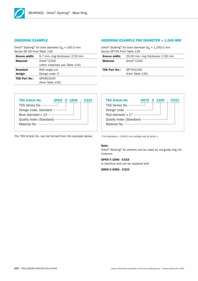
276 • TRELLEBORG SEALING SOLUTIONS Latest information available at www.tss.trelleborg.com • Edition December 2015
BEARINGS · Orkot® Slydring® - Wear Ring
ORDERInG ExAMPLE
Orkot® Slydring® for bore diameter DN = 100.0 mm Series GP 69 from Table 139
Groove width: 9.7 mm, ring thickness: 2.50 mm
Material: Orkot® C333 (other materials see Table 116)
Standard design:
With angle cut Design code: 0
TSS Part no.: GP6901000 (from Table 145)
Material No.
TSS Series No.
TSS Article No.
Bore diameter x 10Quality Index (Standard)
Design code, standard
C333GP69 -0 1000
The TSS Article No. can be formed from the example above.
ORDERInG ExAMPLE FOR DIAMETER > 1,000 MM
Orkot®Slydring® for bore diameter DN = 1,200.0 mm Series GP75X from Table 139
Groove width: 25.00 mm, ring thickness: 2.50 mm
Material: Orkot® C333
TSS Part no.: GP75X1200 (from Table 145)
Material No.
TSS Series No.
TSS Article No.
Rod diameter x 1*Quality Index (Standard)
Design code
C333GR75 -X 1200
* For diameters ≥ 1,000.0 mm multiply only by factor 1.
note:Orkot® Slydring® for pistons can be used as rod guide ring, for instance.
GP69 0 1000 - C333is identical and can be replaced with
GR69 0 0950 - C333
FBP_neues_Layout_2015.indb 276 17.10.2016 13:38:01

Slydring® - Wear Ring
TRELLEBORG SEALING SOLUTIONS • 277Latest information available at www.tss.trelleborg.com • Edition December 2015
FBP_neues_Layout_2015.indb 277 17.10.2016 13:38:01
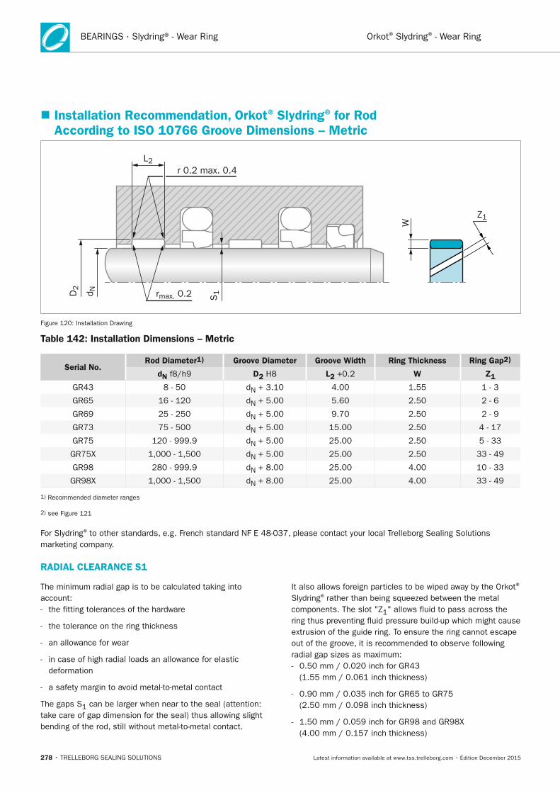
BEARINGS · Slydring® - Wear Ring
278 • TRELLEBORG SEALING SOLUTIONS Latest information available at www.tss.trelleborg.com • Edition December 2015
Orkot® Slydring® - Wear Ring
Z1
r 0.2 max. 0.4
rmax. 0.2
L2
S1D
2
d N
W
Figure 120: Installation Drawing
Table 142: Installation Dimensions – Metric
Serial no. Rod Diameter1) Groove Diameter Groove Width Ring Thickness Ring Gap2)
dn f8/h9 D2 H8 L2 +0.2 W Z1
GR43 8 - 50 dN + 3.10 4.00 1.55 1 - 3
GR65 16 - 120 dN + 5.00 5.60 2.50 2 - 6
GR69 25 - 250 dN + 5.00 9.70 2.50 2 - 9
GR73 75 - 500 dN + 5.00 15.00 2.50 4 - 17
GR75 120 - 999.9 dN + 5.00 25.00 2.50 5 - 33
GR75X 1,000 - 1,500 dN + 5.00 25.00 2.50 33 - 49
GR98 280 - 999.9 dN + 8.00 25.00 4.00 10 - 33
GR98X 1,000 - 1,500 dN + 8.00 25.00 4.00 33 - 49
1) Recommended diameter ranges
2) see Figure 121
For Slydring® to other standards, e.g. French standard NF E 48-037, please contact your local Trelleborg Sealing Solutions marketing company.
� Installation Recommendation, Orkot® Slydring® for Rod According to ISO 10766 Groove Dimensions – Metric
RADIAL CLEARAnCE S1
The minimum radial gap is to be calculated taking into account: - the fitting tolerances of the hardware
- the tolerance on the ring thickness
- an allowance for wear
- in case of high radial loads an allowance for elastic deformation
- a safety margin to avoid metal-to-metal contact
The gaps S1 can be larger when near to the seal (attention: take care of gap dimension for the seal) thus allowing slight bending of the rod, still without metal-to-metal contact.
It also allows foreign particles to be wiped away by the Orkot®
Slydring® rather than being squeezed between the metal components. The slot "Z1" allows fluid to pass across the ring thus preventing fluid pressure build-up which might cause extrusion of the guide ring. To ensure the ring cannot escape out of the groove, it is recommended to observe following radial gap sizes as maximum: - 0.50 mm / 0.020 inch for GR43
(1.55 mm / 0.061 inch thickness)
- 0.90 mm / 0.035 inch for GR65 to GR75 (2.50 mm / 0.098 inch thickness)
- 1.50 mm / 0.059 inch for GR98 and GR98X (4.00 mm / 0.157 inch thickness)
FBP_neues_Layout_2015.indb 278 17.10.2016 13:38:01
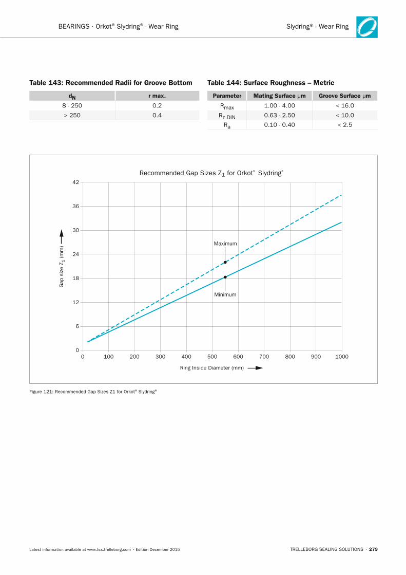
Slydring® - Wear Ring
TRELLEBORG SEALING SOLUTIONS • 279Latest information available at www.tss.trelleborg.com • Edition December 2015
BEARINGS · Orkot® Slydring® - Wear Ring
Table 143: Recommended Radii for Groove Bottom
dn r max.
8 - 250 0.2
> 250 0.4
Table 144: Surface Roughness – Metric
Parameter Mating Surface μm Groove Surface μm
Rmax 1.00 - 4.00 < 16.0
Rz DIN 0.63 - 2.50 < 10.0
Ra 0.10 - 0.40 < 2.5
Ring Inside Diameter (mm)
Maximum
Minimum
0 100 200 300 400 500 600 700 800 900 10000
6
12
18
24
30
36
42
Recommended Gap Sizes Z1 for Orkot® Slydring®
Gap
siz
e Z 1
(m
m)
Figure 121: Recommended Gap Sizes Z1 for Orkot® Slydring®
FBP_neues_Layout_2015.indb 279 17.10.2016 13:38:02
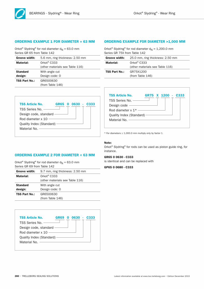
BEARINGS · Slydring® - Wear Ring
280 • TRELLEBORG SEALING SOLUTIONS Latest information available at www.tss.trelleborg.com • Edition December 2015
Orkot® Slydring® - Wear Ring
ORDERInG ExAMPLE 1 FOR DIAMETER = 63 MM
Orkot® Slydring® for rod diameter dN = 63.0 mm Series GR 65 from Table 142
Groove width: 5.6 mm, ring thickness: 2.50 mm
Material: Orkot® C333 (other materials see Table 116)
Standard design:
With angle cut Design code: 0
TSS Part no.: GR6500630 (from Table 146)
Material No.
TSS Series No.
TSS Article No.
Rod diameter x 10Quality Index (Standard)
Design code, standard
C333GR65 -0 0630
ORDERInG ExAMPLE 2 FOR DIAMETER = 63 MM
Orkot® Slydring® for rod diameter dN = 63.0 mm Series GR 69 from Table 142
Groove width: 9.7 mm, ring thickness: 2.50 mm
Material: Orkot® C333 (other materials see Table 116)
Standard design:
With angle cut Design code: 0
TSS Part no.: GR6500630 (from Table 146)
Material No.
TSS Series No.
TSS Article No.
Rod diameter x 10Quality Index (Standard)
Design code, standard
C333GR69 -0 0630
ORDERInG ExAMPLE FOR DIAMETER >1,000 MM
Orkot® Slydring® for rod diameter dN = 1,200.0 mm Series GR 75X from Table 142
Groove width: 25.0 mm, ring thickness: 2.50 mm
Material: Orkot® C333 (other materials see Table 116)
TSS Part no.: GR75X1200 (from Table 146)
Material No.
TSS Series No.
TSS Article No.
Rod diameter x 1*Quality Index (Standard)
Design code
C333GR75 -X 1200
* For diameters ≥ 1,000.0 mm multiply only by factor 1.
note:Orkot® Slydring® for rods can be used as piston guide ring, for instance.
GR65 0 0630 - C333is identical and can be replaced with
GP65 0 0680 - C333
FBP_neues_Layout_2015.indb 280 17.10.2016 13:38:03
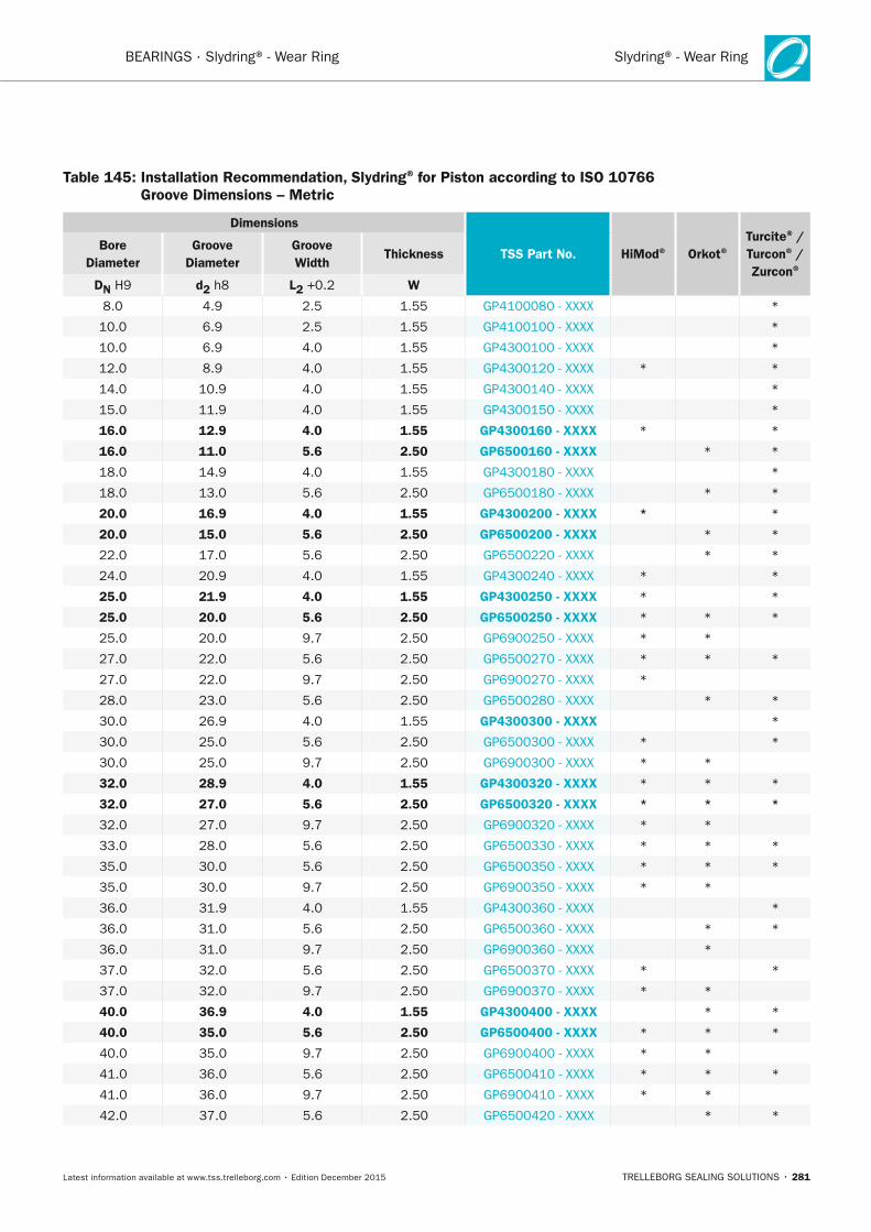
Slydring® - Wear Ring
TRELLEBORG SEALING SOLUTIONS • 281Latest information available at www.tss.trelleborg.com • Edition December 2015
BEARINGS · Slydring® - Wear Ring
Table 145: Installation Recommendation, Slydring® for Piston according to ISO 10766 Groove Dimensions – Metric
Dimensions
TSS Part no. HiMod® Orkot®Turcite® /
Turcon® / Zurcon®
Bore Diameter
Groove Diameter
Groove Width
Thickness
Dn H9 d2 h8 L2 +0.2 W
8.0 4.9 2.5 1.55 GP4100080 - XXXX *
10.0 6.9 2.5 1.55 GP4100100 - XXXX *
10.0 6.9 4.0 1.55 GP4300100 - XXXX *
12.0 8.9 4.0 1.55 GP4300120 - XXXX * *
14.0 10.9 4.0 1.55 GP4300140 - XXXX *
15.0 11.9 4.0 1.55 GP4300150 - XXXX *
16.0 12.9 4.0 1.55 GP4300160 - xxxx * *
16.0 11.0 5.6 2.50 GP6500160 - xxxx * *
18.0 14.9 4.0 1.55 GP4300180 - XXXX *
18.0 13.0 5.6 2.50 GP6500180 - XXXX * *
20.0 16.9 4.0 1.55 GP4300200 - xxxx * *
20.0 15.0 5.6 2.50 GP6500200 - xxxx * *
22.0 17.0 5.6 2.50 GP6500220 - XXXX * *
24.0 20.9 4.0 1.55 GP4300240 - XXXX * *
25.0 21.9 4.0 1.55 GP4300250 - xxxx * *
25.0 20.0 5.6 2.50 GP6500250 - xxxx * * *
25.0 20.0 9.7 2.50 GP6900250 - XXXX * *
27.0 22.0 5.6 2.50 GP6500270 - XXXX * * *
27.0 22.0 9.7 2.50 GP6900270 - XXXX *
28.0 23.0 5.6 2.50 GP6500280 - XXXX * *
30.0 26.9 4.0 1.55 GP4300300 - xxxx *
30.0 25.0 5.6 2.50 GP6500300 - XXXX * *
30.0 25.0 9.7 2.50 GP6900300 - XXXX * *
32.0 28.9 4.0 1.55 GP4300320 - xxxx * * *
32.0 27.0 5.6 2.50 GP6500320 - xxxx * * *
32.0 27.0 9.7 2.50 GP6900320 - XXXX * *
33.0 28.0 5.6 2.50 GP6500330 - XXXX * * *
35.0 30.0 5.6 2.50 GP6500350 - XXXX * * *
35.0 30.0 9.7 2.50 GP6900350 - XXXX * *
36.0 31.9 4.0 1.55 GP4300360 - XXXX *
36.0 31.0 5.6 2.50 GP6500360 - XXXX * *
36.0 31.0 9.7 2.50 GP6900360 - XXXX *
37.0 32.0 5.6 2.50 GP6500370 - XXXX * *
37.0 32.0 9.7 2.50 GP6900370 - XXXX * *
40.0 36.9 4.0 1.55 GP4300400 - xxxx * *
40.0 35.0 5.6 2.50 GP6500400 - xxxx * * *
40.0 35.0 9.7 2.50 GP6900400 - XXXX * *
41.0 36.0 5.6 2.50 GP6500410 - XXXX * * *
41.0 36.0 9.7 2.50 GP6900410 - XXXX * *
42.0 37.0 5.6 2.50 GP6500420 - XXXX * *
FBP_neues_Layout_2015.indb 281 17.10.2016 13:38:03
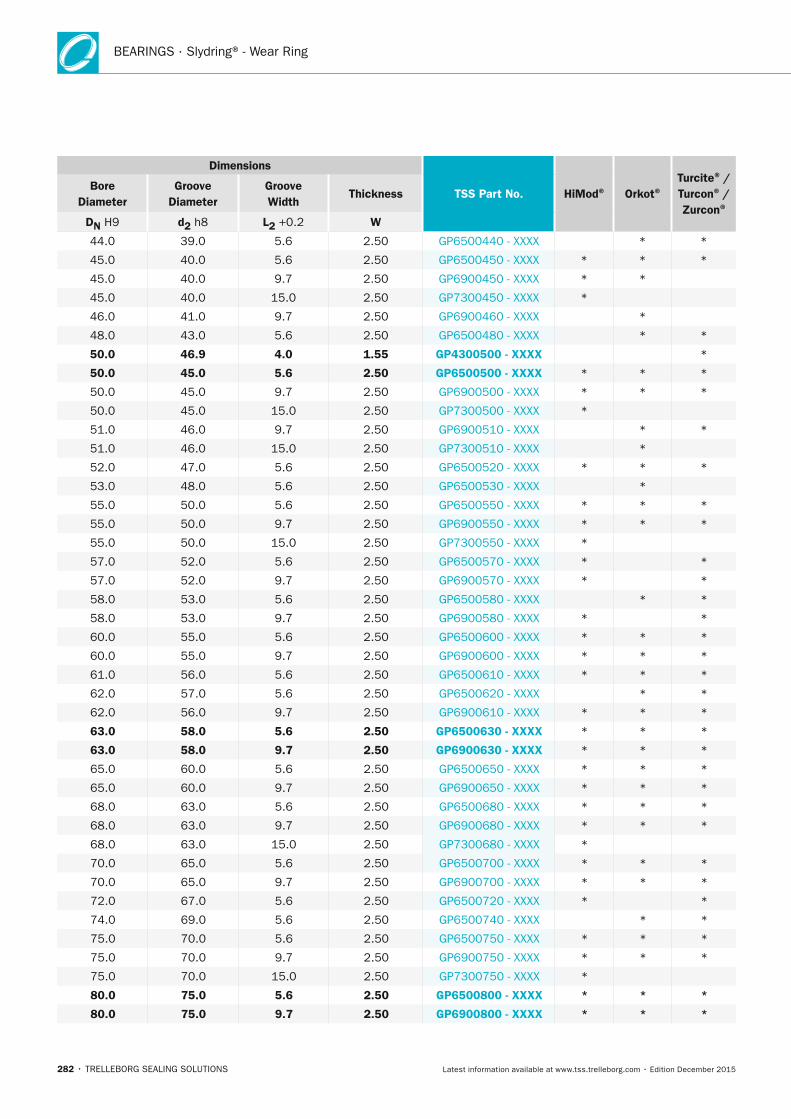
BEARINGS · Slydring® - Wear Ring
282 • TRELLEBORG SEALING SOLUTIONS Latest information available at www.tss.trelleborg.com • Edition December 2015
Dimensions
TSS Part no. HiMod® Orkot®Turcite® /
Turcon® / Zurcon®
Bore Diameter
Groove Diameter
Groove Width
Thickness
Dn H9 d2 h8 L2 +0.2 W
44.0 39.0 5.6 2.50 GP6500440 - XXXX * *
45.0 40.0 5.6 2.50 GP6500450 - XXXX * * *
45.0 40.0 9.7 2.50 GP6900450 - XXXX * *
45.0 40.0 15.0 2.50 GP7300450 - XXXX *
46.0 41.0 9.7 2.50 GP6900460 - XXXX *
48.0 43.0 5.6 2.50 GP6500480 - XXXX * *
50.0 46.9 4.0 1.55 GP4300500 - xxxx *
50.0 45.0 5.6 2.50 GP6500500 - xxxx * * *
50.0 45.0 9.7 2.50 GP6900500 - XXXX * * *
50.0 45.0 15.0 2.50 GP7300500 - XXXX *
51.0 46.0 9.7 2.50 GP6900510 - XXXX * *
51.0 46.0 15.0 2.50 GP7300510 - XXXX *
52.0 47.0 5.6 2.50 GP6500520 - XXXX * * *
53.0 48.0 5.6 2.50 GP6500530 - XXXX *
55.0 50.0 5.6 2.50 GP6500550 - XXXX * * *
55.0 50.0 9.7 2.50 GP6900550 - XXXX * * *
55.0 50.0 15.0 2.50 GP7300550 - XXXX *
57.0 52.0 5.6 2.50 GP6500570 - XXXX * *
57.0 52.0 9.7 2.50 GP6900570 - XXXX * *
58.0 53.0 5.6 2.50 GP6500580 - XXXX * *
58.0 53.0 9.7 2.50 GP6900580 - XXXX * *
60.0 55.0 5.6 2.50 GP6500600 - XXXX * * *
60.0 55.0 9.7 2.50 GP6900600 - XXXX * * *
61.0 56.0 5.6 2.50 GP6500610 - XXXX * * *
62.0 57.0 5.6 2.50 GP6500620 - XXXX * *
62.0 56.0 9.7 2.50 GP6900610 - XXXX * * *
63.0 58.0 5.6 2.50 GP6500630 - xxxx * * *
63.0 58.0 9.7 2.50 GP6900630 - xxxx * * *
65.0 60.0 5.6 2.50 GP6500650 - XXXX * * *
65.0 60.0 9.7 2.50 GP6900650 - XXXX * * *
68.0 63.0 5.6 2.50 GP6500680 - XXXX * * *
68.0 63.0 9.7 2.50 GP6900680 - XXXX * * *
68.0 63.0 15.0 2.50 GP7300680 - XXXX *
70.0 65.0 5.6 2.50 GP6500700 - XXXX * * *
70.0 65.0 9.7 2.50 GP6900700 - XXXX * * *
72.0 67.0 5.6 2.50 GP6500720 - XXXX * *
74.0 69.0 5.6 2.50 GP6500740 - XXXX * *
75.0 70.0 5.6 2.50 GP6500750 - XXXX * * *
75.0 70.0 9.7 2.50 GP6900750 - XXXX * * *
75.0 70.0 15.0 2.50 GP7300750 - XXXX *
80.0 75.0 5.6 2.50 GP6500800 - xxxx * * *
80.0 75.0 9.7 2.50 GP6900800 - xxxx * * *
FBP_neues_Layout_2015.indb 282 17.10.2016 13:38:03
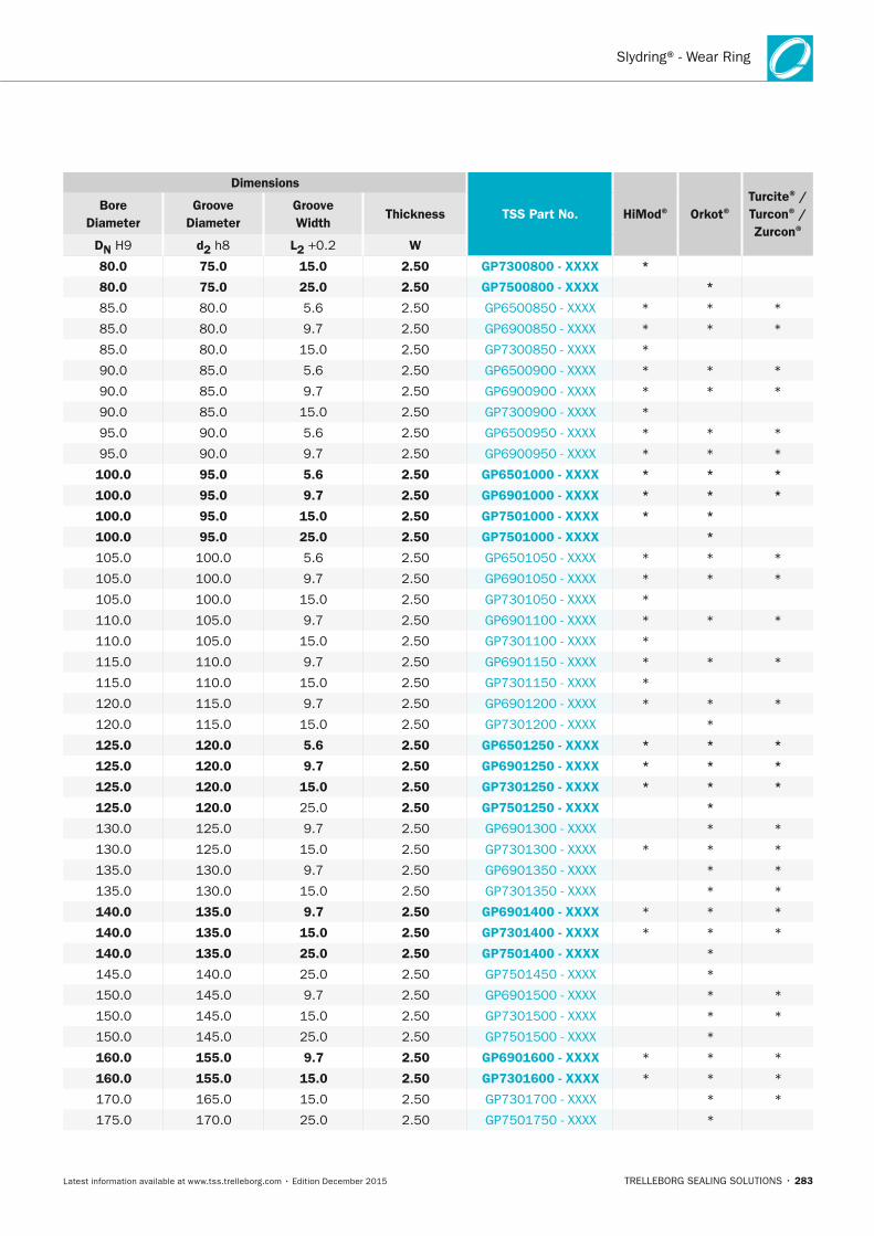
Slydring® - Wear Ring
TRELLEBORG SEALING SOLUTIONS • 283Latest information available at www.tss.trelleborg.com • Edition December 2015
Dimensions
TSS Part no. HiMod® Orkot®Turcite® /
Turcon® / Zurcon®
Bore Diameter
Groove Diameter
Groove Width
Thickness
Dn H9 d2 h8 L2 +0.2 W
80.0 75.0 15.0 2.50 GP7300800 - xxxx *
80.0 75.0 25.0 2.50 GP7500800 - xxxx *
85.0 80.0 5.6 2.50 GP6500850 - XXXX * * *
85.0 80.0 9.7 2.50 GP6900850 - XXXX * * *
85.0 80.0 15.0 2.50 GP7300850 - XXXX *
90.0 85.0 5.6 2.50 GP6500900 - XXXX * * *
90.0 85.0 9.7 2.50 GP6900900 - XXXX * * *
90.0 85.0 15.0 2.50 GP7300900 - XXXX *
95.0 90.0 5.6 2.50 GP6500950 - XXXX * * *
95.0 90.0 9.7 2.50 GP6900950 - XXXX * * *
100.0 95.0 5.6 2.50 GP6501000 - xxxx * * *
100.0 95.0 9.7 2.50 GP6901000 - xxxx * * *
100.0 95.0 15.0 2.50 GP7501000 - xxxx * *
100.0 95.0 25.0 2.50 GP7501000 - xxxx *
105.0 100.0 5.6 2.50 GP6501050 - XXXX * * *
105.0 100.0 9.7 2.50 GP6901050 - XXXX * * *
105.0 100.0 15.0 2.50 GP7301050 - XXXX *
110.0 105.0 9.7 2.50 GP6901100 - XXXX * * *
110.0 105.0 15.0 2.50 GP7301100 - XXXX *
115.0 110.0 9.7 2.50 GP6901150 - XXXX * * *
115.0 110.0 15.0 2.50 GP7301150 - XXXX *
120.0 115.0 9.7 2.50 GP6901200 - XXXX * * *
120.0 115.0 15.0 2.50 GP7301200 - XXXX *
125.0 120.0 5.6 2.50 GP6501250 - xxxx * * *
125.0 120.0 9.7 2.50 GP6901250 - xxxx * * *
125.0 120.0 15.0 2.50 GP7301250 - xxxx * * *
125.0 120.0 25.0 2.50 GP7501250 - xxxx *
130.0 125.0 9.7 2.50 GP6901300 - XXXX * *
130.0 125.0 15.0 2.50 GP7301300 - XXXX * * *
135.0 130.0 9.7 2.50 GP6901350 - XXXX * *
135.0 130.0 15.0 2.50 GP7301350 - XXXX * *
140.0 135.0 9.7 2.50 GP6901400 - xxxx * * *
140.0 135.0 15.0 2.50 GP7301400 - xxxx * * *
140.0 135.0 25.0 2.50 GP7501400 - xxxx *
145.0 140.0 25.0 2.50 GP7501450 - XXXX *
150.0 145.0 9.7 2.50 GP6901500 - XXXX * *
150.0 145.0 15.0 2.50 GP7301500 - XXXX * *
150.0 145.0 25.0 2.50 GP7501500 - XXXX *
160.0 155.0 9.7 2.50 GP6901600 - xxxx * * *
160.0 155.0 15.0 2.50 GP7301600 - xxxx * * *
170.0 165.0 15.0 2.50 GP7301700 - XXXX * *
175.0 170.0 25.0 2.50 GP7501750 - XXXX *
FBP_neues_Layout_2015.indb 283 17.10.2016 13:38:04
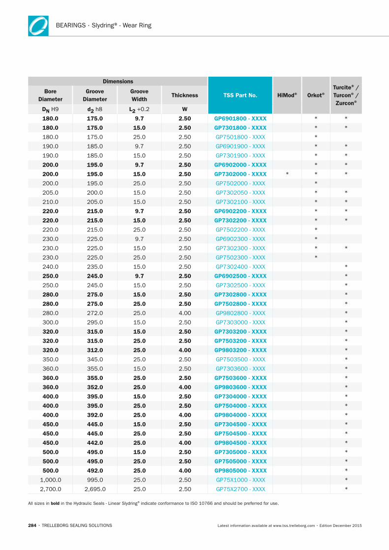
BEARINGS · Slydring® - Wear Ring
284 • TRELLEBORG SEALING SOLUTIONS Latest information available at www.tss.trelleborg.com • Edition December 2015
Dimensions
TSS Part no. HiMod® Orkot®Turcite® /
Turcon® / Zurcon®
Bore Diameter
Groove Diameter
Groove Width
Thickness
Dn H9 d2 h8 L2 +0.2 W
180.0 175.0 9.7 2.50 GP6901800 - xxxx * *
180.0 175.0 15.0 2.50 GP7301800 - xxxx * *
180.0 175.0 25.0 2.50 GP7501800 - XXXX *
190.0 185.0 9.7 2.50 GP6901900 - XXXX * *
190.0 185.0 15.0 2.50 GP7301900 - XXXX * *
200.0 195.0 9.7 2.50 GP6902000 - xxxx * *
200.0 195.0 15.0 2.50 GP7302000 - xxxx * * *
200.0 195.0 25.0 2.50 GP7502000 - XXXX *
205.0 200.0 15.0 2.50 GP7302050 - XXXX * *
210.0 205.0 15.0 2.50 GP7302100 - XXXX * *
220.0 215.0 9.7 2.50 GP6902200 - xxxx * *
220.0 215.0 15.0 2.50 GP7302200 - xxxx * *
220.0 215.0 25.0 2.50 GP7502200 - XXXX *
230.0 225.0 9.7 2.50 GP6902300 - XXXX *
230.0 225.0 15.0 2.50 GP7302300 - XXXX * *
230.0 225.0 25.0 2.50 GP7502300 - XXXX *
240.0 235.0 15.0 2.50 GP7302400 - XXXX *
250.0 245.0 9.7 2.50 GP6902500 - xxxx *
250.0 245.0 15.0 2.50 GP7302500 - XXXX *
280.0 275.0 15.0 2.50 GP7302800 - xxxx *
280.0 275.0 25.0 2.50 GP7502800 - xxxx *
280.0 272.0 25.0 4.00 GP9802800 - XXXX *
300.0 295.0 15.0 2.50 GP7303000 - XXXX *
320.0 315.0 15.0 2.50 GP7303200 - xxxx *
320.0 315.0 25.0 2.50 GP7503200 - xxxx *
320.0 312.0 25.0 4.00 GP9803200 - xxxx *
350.0 345.0 25.0 2.50 GP7503500 - XXXX *
360.0 355.0 15.0 2.50 GP7303600 - XXXX *
360.0 355.0 25.0 2.50 GP7503600 - xxxx *
360.0 352.0 25.0 4.00 GP9803600 - xxxx *
400.0 395.0 15.0 2.50 GP7304000 - xxxx *
400.0 395.0 25.0 2.50 GP7504000 - xxxx *
400.0 392.0 25.0 4.00 GP9804000 - xxxx *
450.0 445.0 15.0 2.50 GP7304500 - xxxx *
450.0 445.0 25.0 2.50 GP7504500 - xxxx *
450.0 442.0 25.0 4.00 GP9804500 - xxxx *
500.0 495.0 15.0 2.50 GP7305000 - xxxx *
500.0 495.0 25.0 2.50 GP7505000 - xxxx *
500.0 492.0 25.0 4.00 GP9805000 - xxxx *
1,000.0 995.0 25.0 2.50 GP75X1000 - XXXX *
2,700.0 2,695.0 25.0 2.50 GP75X2700 - XXXX *
All sizes in bold in the Hydraulic Seals - Linear Slydring® indicate conformance to ISO 10766 and should be preferred for use.
FBP_neues_Layout_2015.indb 284 17.10.2016 13:38:04
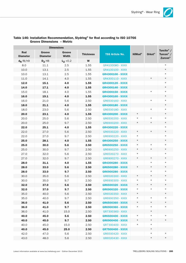
Slydring® - Wear Ring
TRELLEBORG SEALING SOLUTIONS • 285Latest information available at www.tss.trelleborg.com • Edition December 2015
Table 146: Installation Recommendation, Slydring® for Rod according to ISO 10766 Groove Dimensions – Metric
Dimensions
TSS Article no. HiMod® Orkot®Turcite® / Turcon® /
Zurcon®
Rod Diameter
Groove Diameter
Groove Width
Thickness
dn f8/h9 D2 H8 L2 +0.2 W
8.0 11.1 2.5 1.55 GR4100080 - XXXX *
10.0 13.1 2.5 1.55 GR4100100 - XXXX *
10.0 13.1 2.5 1.55 GR4300100 - xxxx *
11.0 14.1 4.0 1.55 GR4300110 - XXXX * *
12.0 15.1 4.0 1.55 GR4300120 - xxxx *
14.0 17.1 4.0 1.55 GR4300140 - xxxx *
15.0 18.1 4.0 1.55 GR4300150 - xxxx * *
16.0 19.1 4.0 1.55 GR4300160 - xxxx *
16.0 21.0 5.6 2.50 GR6500160 - XXXX * *
18.0 21.1 4.0 1.55 GR4300180 - xxxx *
18.0 23.0 5.6 2.50 GR6500180 - XXXX * *
20.0 23.1 4.0 1.55 GR4300200 - xxxx * *
20.0 25.0 5.6 2.50 GR6500200 - XXXX * * *
20.0 25.0 9.7 2.50 GR6900200 - XXXX * * *
22.0 25.1 4.0 1.55 GR4300220 - xxxx *
22.0 27.0 5.6 2.50 GR6500220 - XXXX * * *
22.0 27.0 9.7 2.50 GR6900220 - XXXX * *
25.0 28.1 4.0 1.55 GR4300250 - xxxx * *
25.0 30.0 5.6 2.50 GR6500250 - xxxx * * *
25.0 30.0 9.7 2.50 GR6900250 - XXXX * * *
27.0 32.0 5.6 2.50 GR6500270 - XXXX * *
27.0 32.0 9.7 2.50 GR6900270 - XXXX * * *
28.0 31.1 4.0 1.55 GR4300280 - xxxx * *
28.0 33.0 5.6 2.50 GR6500280 - xxxx * * *
28.0 33.0 9.7 2.50 GR6900280 - xxxx * *
30.0 35.0 5.6 2.50 GR6500300 - XXXX * * *
30.0 35.0 9.7 2.50 GR6900300 - XXXX * * *
32.0 37.0 5.6 2.50 GR6500320 - xxxx * * *
32.0 37.0 9.7 2.50 GR6900320 - xxxx * * *
35.0 40.0 5.6 2.50 GR6500350 - XXXX * *
35.0 40.0 9.7 2.50 GR6900350 - XXXX * * *
36.0 41.0 5.6 2.50 GR6500360 - xxxx * * *
36.0 41.0 9.7 2.50 GR6900360 - xxxx * * *
36.0 41.0 15.0 2.50 GR7300360 - XXXX *
40.0 45.0 5.6 2.50 GR6500400 - xxxx * * *
40.0 45.0 9.7 2.50 GR6900400 - xxxx * * *
40.0 45.0 15.0 2.50 GR7300400 - XXXX * *
40.0 45.0 25.0 2.50 GR7500400 - xxxx *
42.0 47.0 5.6 2.50 GR6500420 - XXXX * *
43.0 48.0 5.6 2.50 GR6500430 - XXXX * *
FBP_neues_Layout_2015.indb 285 17.10.2016 13:38:05
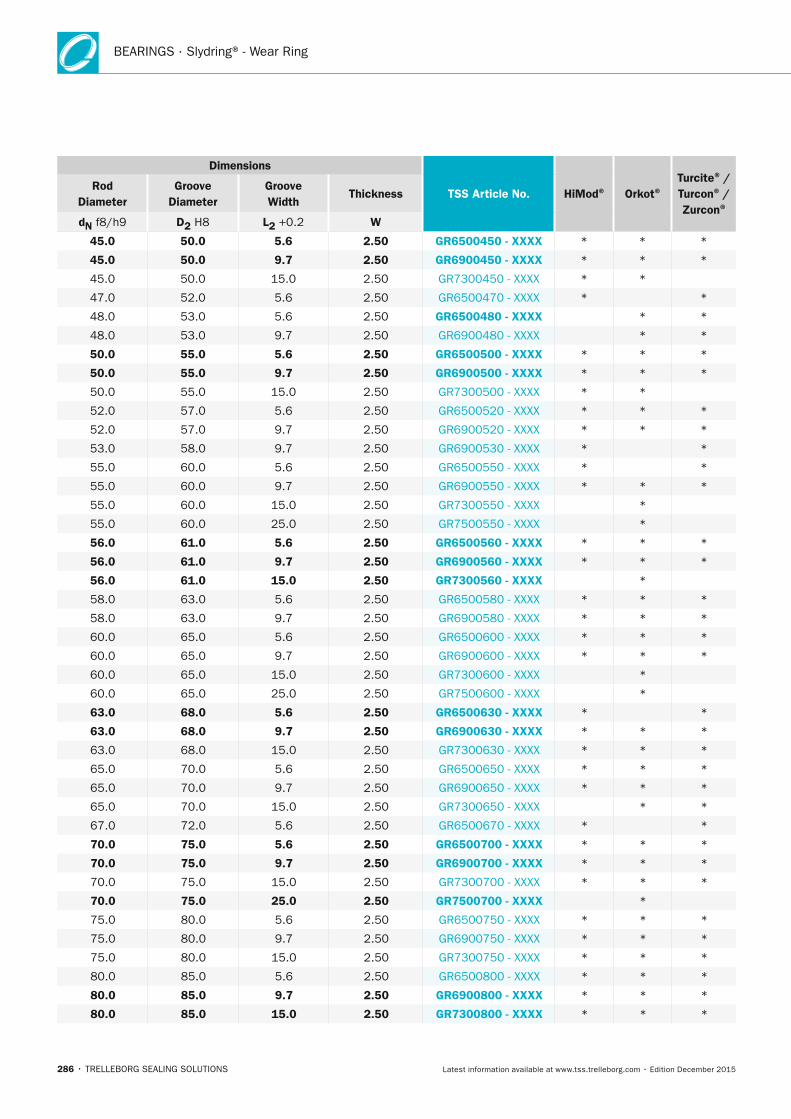
BEARINGS · Slydring® - Wear Ring
286 • TRELLEBORG SEALING SOLUTIONS Latest information available at www.tss.trelleborg.com • Edition December 2015
Dimensions
TSS Article no. HiMod® Orkot®Turcite® / Turcon® /
Zurcon®
Rod Diameter
Groove Diameter
Groove Width
Thickness
dn f8/h9 D2 H8 L2 +0.2 W
45.0 50.0 5.6 2.50 GR6500450 - xxxx * * *
45.0 50.0 9.7 2.50 GR6900450 - xxxx * * *
45.0 50.0 15.0 2.50 GR7300450 - XXXX * *
47.0 52.0 5.6 2.50 GR6500470 - XXXX * *
48.0 53.0 5.6 2.50 GR6500480 - xxxx * *
48.0 53.0 9.7 2.50 GR6900480 - XXXX * *
50.0 55.0 5.6 2.50 GR6500500 - xxxx * * *
50.0 55.0 9.7 2.50 GR6900500 - xxxx * * *
50.0 55.0 15.0 2.50 GR7300500 - XXXX * *
52.0 57.0 5.6 2.50 GR6500520 - XXXX * * *
52.0 57.0 9.7 2.50 GR6900520 - XXXX * * *
53.0 58.0 9.7 2.50 GR6900530 - XXXX * *
55.0 60.0 5.6 2.50 GR6500550 - XXXX * *
55.0 60.0 9.7 2.50 GR6900550 - XXXX * * *
55.0 60.0 15.0 2.50 GR7300550 - XXXX *
55.0 60.0 25.0 2.50 GR7500550 - XXXX *
56.0 61.0 5.6 2.50 GR6500560 - xxxx * * *
56.0 61.0 9.7 2.50 GR6900560 - xxxx * * *
56.0 61.0 15.0 2.50 GR7300560 - xxxx *
58.0 63.0 5.6 2.50 GR6500580 - XXXX * * *
58.0 63.0 9.7 2.50 GR6900580 - XXXX * * *
60.0 65.0 5.6 2.50 GR6500600 - XXXX * * *
60.0 65.0 9.7 2.50 GR6900600 - XXXX * * *
60.0 65.0 15.0 2.50 GR7300600 - XXXX *
60.0 65.0 25.0 2.50 GR7500600 - XXXX *
63.0 68.0 5.6 2.50 GR6500630 - xxxx * *
63.0 68.0 9.7 2.50 GR6900630 - xxxx * * *
63.0 68.0 15.0 2.50 GR7300630 - XXXX * * *
65.0 70.0 5.6 2.50 GR6500650 - XXXX * * *
65.0 70.0 9.7 2.50 GR6900650 - XXXX * * *
65.0 70.0 15.0 2.50 GR7300650 - XXXX * *
67.0 72.0 5.6 2.50 GR6500670 - XXXX * *
70.0 75.0 5.6 2.50 GR6500700 - xxxx * * *
70.0 75.0 9.7 2.50 GR6900700 - xxxx * * *
70.0 75.0 15.0 2.50 GR7300700 - XXXX * * *
70.0 75.0 25.0 2.50 GR7500700 - xxxx *
75.0 80.0 5.6 2.50 GR6500750 - XXXX * * *
75.0 80.0 9.7 2.50 GR6900750 - XXXX * * *
75.0 80.0 15.0 2.50 GR7300750 - XXXX * * *
80.0 85.0 5.6 2.50 GR6500800 - XXXX * * *
80.0 85.0 9.7 2.50 GR6900800 - xxxx * * *
80.0 85.0 15.0 2.50 GR7300800 - xxxx * * *
FBP_neues_Layout_2015.indb 286 17.10.2016 13:38:05
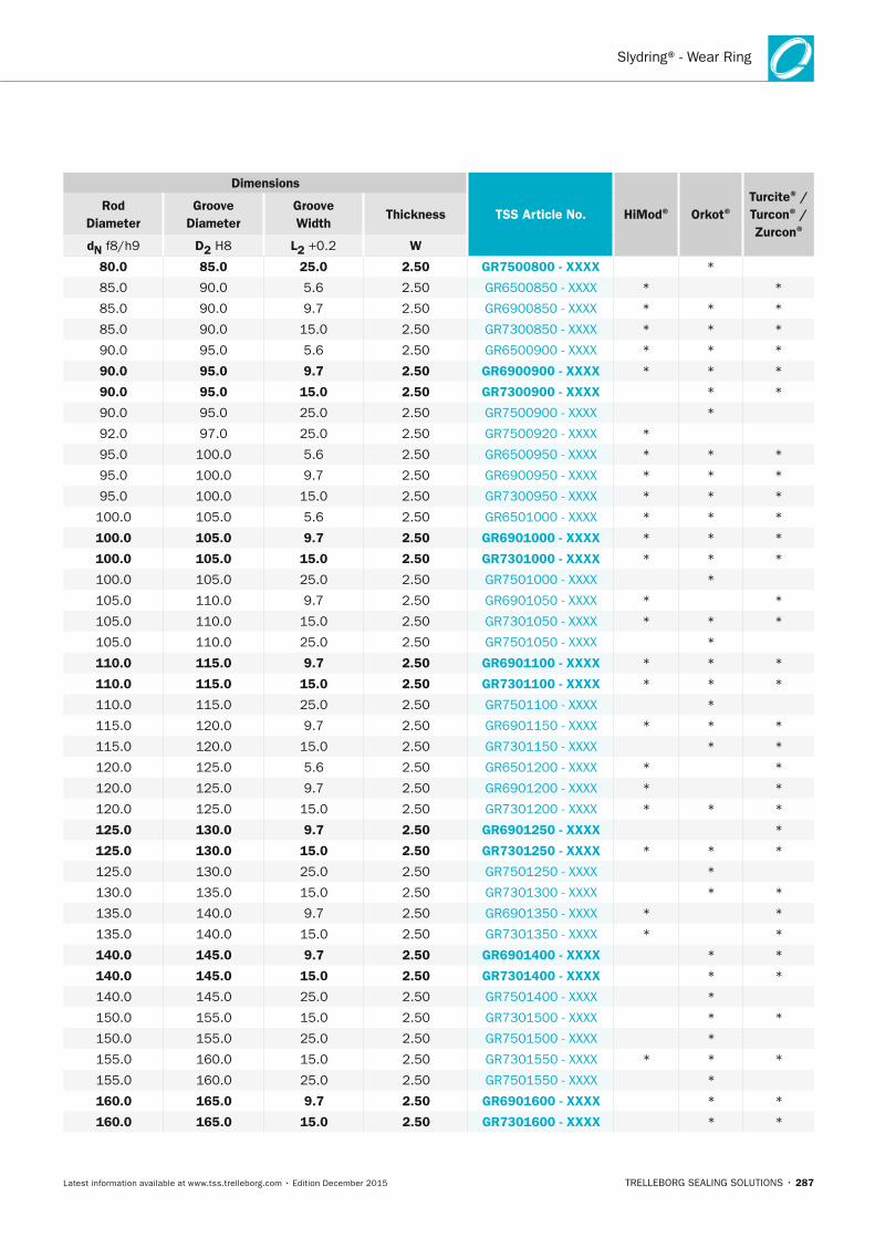
Slydring® - Wear Ring
TRELLEBORG SEALING SOLUTIONS • 287Latest information available at www.tss.trelleborg.com • Edition December 2015
Dimensions
TSS Article no. HiMod® Orkot®Turcite® / Turcon® /
Zurcon®
Rod Diameter
Groove Diameter
Groove Width
Thickness
dn f8/h9 D2 H8 L2 +0.2 W
80.0 85.0 25.0 2.50 GR7500800 - xxxx *
85.0 90.0 5.6 2.50 GR6500850 - XXXX * *
85.0 90.0 9.7 2.50 GR6900850 - XXXX * * *
85.0 90.0 15.0 2.50 GR7300850 - XXXX * * *
90.0 95.0 5.6 2.50 GR6500900 - XXXX * * *
90.0 95.0 9.7 2.50 GR6900900 - xxxx * * *
90.0 95.0 15.0 2.50 GR7300900 - xxxx * *
90.0 95.0 25.0 2.50 GR7500900 - XXXX *
92.0 97.0 25.0 2.50 GR7500920 - XXXX *
95.0 100.0 5.6 2.50 GR6500950 - XXXX * * *
95.0 100.0 9.7 2.50 GR6900950 - XXXX * * *
95.0 100.0 15.0 2.50 GR7300950 - XXXX * * *
100.0 105.0 5.6 2.50 GR6501000 - XXXX * * *
100.0 105.0 9.7 2.50 GR6901000 - xxxx * * *
100.0 105.0 15.0 2.50 GR7301000 - xxxx * * *
100.0 105.0 25.0 2.50 GR7501000 - XXXX *
105.0 110.0 9.7 2.50 GR6901050 - XXXX * *
105.0 110.0 15.0 2.50 GR7301050 - XXXX * * *
105.0 110.0 25.0 2.50 GR7501050 - XXXX *
110.0 115.0 9.7 2.50 GR6901100 - xxxx * * *
110.0 115.0 15.0 2.50 GR7301100 - xxxx * * *
110.0 115.0 25.0 2.50 GR7501100 - XXXX *
115.0 120.0 9.7 2.50 GR6901150 - XXXX * * *
115.0 120.0 15.0 2.50 GR7301150 - XXXX * *
120.0 125.0 5.6 2.50 GR6501200 - XXXX * *
120.0 125.0 9.7 2.50 GR6901200 - XXXX * *
120.0 125.0 15.0 2.50 GR7301200 - XXXX * * *
125.0 130.0 9.7 2.50 GR6901250 - xxxx *
125.0 130.0 15.0 2.50 GR7301250 - xxxx * * *
125.0 130.0 25.0 2.50 GR7501250 - XXXX *
130.0 135.0 15.0 2.50 GR7301300 - XXXX * *
135.0 140.0 9.7 2.50 GR6901350 - XXXX * *
135.0 140.0 15.0 2.50 GR7301350 - XXXX * *
140.0 145.0 9.7 2.50 GR6901400 - xxxx * *
140.0 145.0 15.0 2.50 GR7301400 - xxxx * *
140.0 145.0 25.0 2.50 GR7501400 - XXXX *
150.0 155.0 15.0 2.50 GR7301500 - XXXX * *
150.0 155.0 25.0 2.50 GR7501500 - XXXX *
155.0 160.0 15.0 2.50 GR7301550 - XXXX * * *
155.0 160.0 25.0 2.50 GR7501550 - XXXX *
160.0 165.0 9.7 2.50 GR6901600 - xxxx * *
160.0 165.0 15.0 2.50 GR7301600 - xxxx * *
FBP_neues_Layout_2015.indb 287 17.10.2016 13:38:06
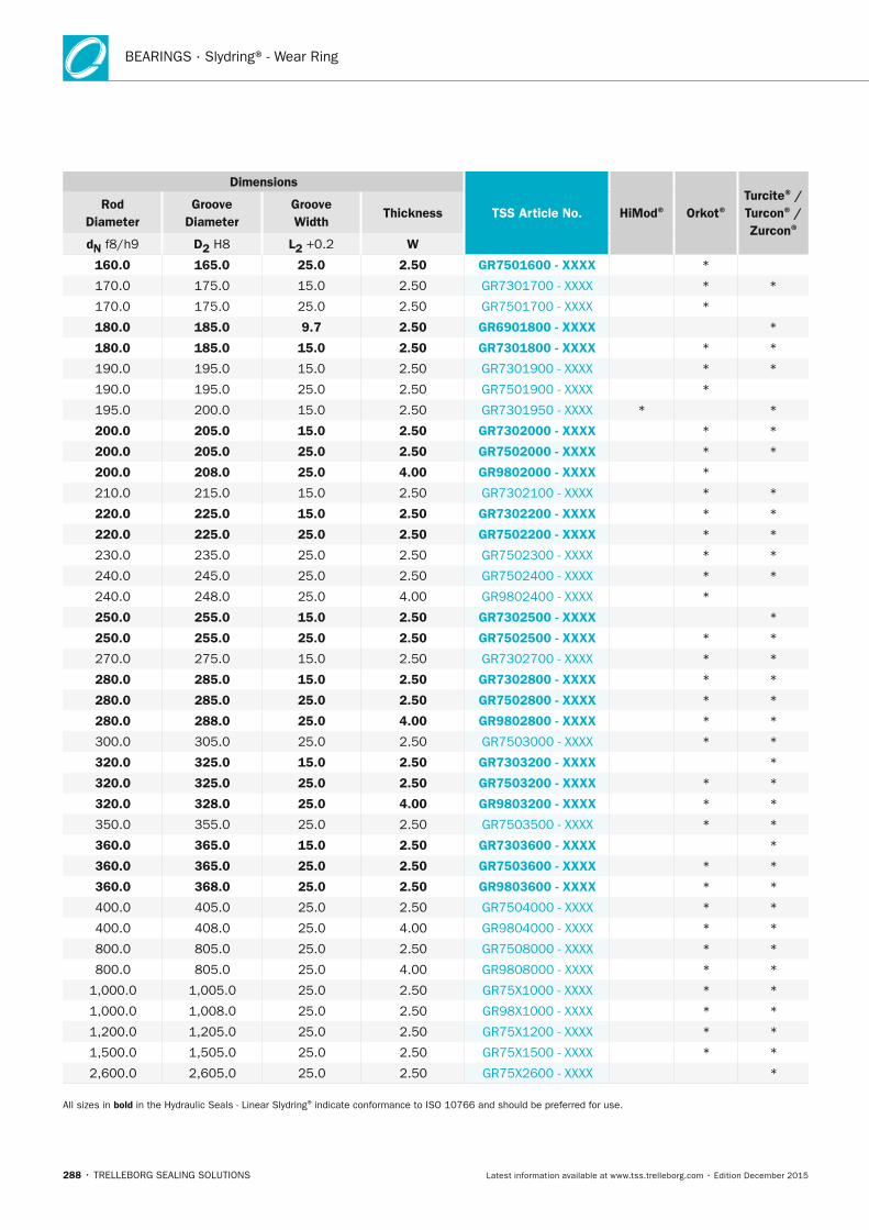
BEARINGS · Slydring® - Wear Ring
288 • TRELLEBORG SEALING SOLUTIONS Latest information available at www.tss.trelleborg.com • Edition December 2015
Dimensions
TSS Article no. HiMod® Orkot®Turcite® / Turcon® /
Zurcon®
Rod Diameter
Groove Diameter
Groove Width
Thickness
dn f8/h9 D2 H8 L2 +0.2 W
160.0 165.0 25.0 2.50 GR7501600 - xxxx *
170.0 175.0 15.0 2.50 GR7301700 - XXXX * *
170.0 175.0 25.0 2.50 GR7501700 - XXXX *
180.0 185.0 9.7 2.50 GR6901800 - xxxx *
180.0 185.0 15.0 2.50 GR7301800 - xxxx * *
190.0 195.0 15.0 2.50 GR7301900 - XXXX * *
190.0 195.0 25.0 2.50 GR7501900 - XXXX *
195.0 200.0 15.0 2.50 GR7301950 - XXXX * *
200.0 205.0 15.0 2.50 GR7302000 - xxxx * *
200.0 205.0 25.0 2.50 GR7502000 - xxxx * *
200.0 208.0 25.0 4.00 GR9802000 - xxxx *
210.0 215.0 15.0 2.50 GR7302100 - XXXX * *
220.0 225.0 15.0 2.50 GR7302200 - xxxx * *
220.0 225.0 25.0 2.50 GR7502200 - xxxx * *
230.0 235.0 25.0 2.50 GR7502300 - XXXX * *
240.0 245.0 25.0 2.50 GR7502400 - XXXX * *
240.0 248.0 25.0 4.00 GR9802400 - XXXX *
250.0 255.0 15.0 2.50 GR7302500 - xxxx *
250.0 255.0 25.0 2.50 GR7502500 - xxxx * *
270.0 275.0 15.0 2.50 GR7302700 - XXXX * *
280.0 285.0 15.0 2.50 GR7302800 - xxxx * *
280.0 285.0 25.0 2.50 GR7502800 - xxxx * *
280.0 288.0 25.0 4.00 GR9802800 - xxxx * *
300.0 305.0 25.0 2.50 GR7503000 - XXXX * *
320.0 325.0 15.0 2.50 GR7303200 - xxxx *
320.0 325.0 25.0 2.50 GR7503200 - xxxx * *
320.0 328.0 25.0 4.00 GR9803200 - xxxx * *
350.0 355.0 25.0 2.50 GR7503500 - XXXX * *
360.0 365.0 15.0 2.50 GR7303600 - xxxx *
360.0 365.0 25.0 2.50 GR7503600 - xxxx * *
360.0 368.0 25.0 2.50 GR9803600 - xxxx * *
400.0 405.0 25.0 2.50 GR7504000 - XXXX * *
400.0 408.0 25.0 4.00 GR9804000 - XXXX * *
800.0 805.0 25.0 2.50 GR7508000 - XXXX * *
800.0 805.0 25.0 4.00 GR9808000 - XXXX * *
1,000.0 1,005.0 25.0 2.50 GR75X1000 - XXXX * *
1,000.0 1,008.0 25.0 2.50 GR98X1000 - XXXX * *
1,200.0 1,205.0 25.0 2.50 GR75X1200 - XXXX * *
1,500.0 1,505.0 25.0 2.50 GR75X1500 - XXXX * *
2,600.0 2,605.0 25.0 2.50 GR75X2600 - XXXX *
All sizes in bold in the Hydraulic Seals - Linear Slydring® indicate conformance to ISO 10766 and should be preferred for use.
FBP_neues_Layout_2015.indb 288 17.10.2016 13:38:06

Slydring® - Wear Ring
TRELLEBORG SEALING SOLUTIONS • 289Latest information available at www.tss.trelleborg.com • Edition December 2015
FBP_neues_Layout_2015.indb 289 17.10.2016 13:38:06
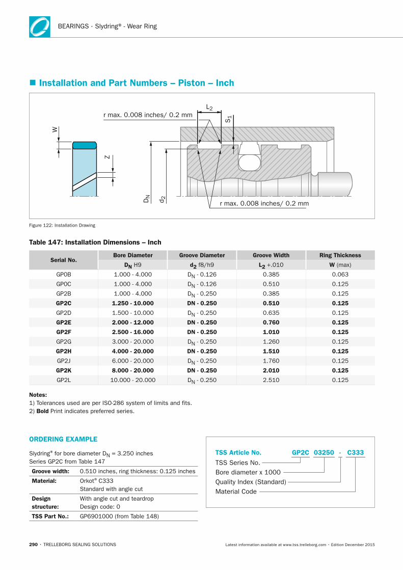
BEARINGS · Slydring® - Wear Ring
290 • TRELLEBORG SEALING SOLUTIONS Latest information available at www.tss.trelleborg.com • Edition December 2015
� Installation and Part numbers – Piston – Inch
r max. 0.008 inches/ 0.2 mm
r max. 0.008 inches/ 0.2 mm
L2Z
S1
DN
d 2
W
Figure 122: Installation Drawing
Table 147: Installation Dimensions – Inch
Serial no.Bore Diameter Groove Diameter Groove Width Ring Thickness
Dn H9 d2 f8/h9 L2 +.010 W (max)
GP0B 1.000 - 4.000 DN - 0.126 0.385 0.063
GP0C 1.000 - 4.000 DN - 0.126 0.510 0.125
GP2B 1.000 - 4.000 DN - 0.250 0.385 0.125
GP2C 1.250 - 10.000 Dn - 0.250 0.510 0.125
GP2D 1.500 - 10.000 DN - 0.250 0.635 0.125
GP2E 2.000 - 12.000 Dn - 0.250 0.760 0.125
GP2F 2.500 - 16.000 Dn - 0.250 1.010 0.125
GP2G 3.000 - 20.000 DN - 0.250 1.260 0.125
GP2H 4.000 - 20.000 Dn - 0.250 1.510 0.125
GP2J 6.000 - 20.000 DN - 0.250 1.760 0.125
GP2K 8.000 - 20.000 Dn - 0.250 2.010 0.125
GP2L 10.000 - 20.000 DN - 0.250 2.510 0.125
notes:1) Tolerances used are per ISO-286 system of limits and fits.2) Bold Print indicates preferred series.
ORDERInG ExAMPLE
Slydring® for bore diameter DN = 3.250 inches Series GP2C from Table 147
Groove width: 0.510 inches, ring thickness: 0.125 inches
Material: Orkot® C333 Standard with angle cut
Design structure:
With angle cut and teardrop Design code: 0
TSS Part no.: GP6901000 (from Table 148)
TSS Series No.
TSS Article No.
Quality Index (Standard)Material Code
Bore diameter x 1000
C333GP2C -03250
FBP_neues_Layout_2015.indb 290 17.10.2016 13:38:07

Slydring® - Wear Ring
TRELLEBORG SEALING SOLUTIONS • 291Latest information available at www.tss.trelleborg.com • Edition December 2015
Table 148: Slydring® for Pistons – Inch
Dimensions
TSS Part no. Bore
Diameter Groove
Diameter Groove Width
Thickness
Dn H9 D2 f8/h9 L2 +0.01 W
1.250 1.000 0.510 0.125 GP2C01250 - xxxx
1.313 1.063 0.510 0.125 GP2C01313 - XXXX
1.375 1.125 0.510 0.125 GP2C01375 - xxxx
1.438 1.188 0.510 0.125 GP2C01438 - XXXX
1.500 1.250 0.510 0.125 GP2C01500 - xxxx
1.563 1.313 0.510 0.125 GP2C01563 - XXXX
1.625 1.375 0.510 0.125 GP2C01625 - xxxx
1.688 1.438 0.510 0.125 GP2C01688 - XXXX
1.750 1.500 0.510 0.125 GP2C01750 - xxxx
1.813 1.563 0.510 0.125 GP2C01813 - XXXX
1.875 1.625 0.510 0.125 GP2C01875 - xxxx
1.938 1.688 0.510 0.125 GP2C01938 - XXXX
2.000 1.750 0.510 0.125 GP2C02000 - xxxx
2.125 1.875 0.510 0.125 GP2C02125 - XXXX
2.250 2.000 0.510 0.125 GP2C02250 - xxxx
2.375 2.125 0.510 0.125 GP2C02375 - XXXX
2.500 2.250 0.510 0.125 GP2C02500 - xxxx
2.625 2.375 0.510 0.125 GP2C02625 - XXXX
2.750 2.500 0.510 0.125 GP2C02750 - xxxx
2.875 2.625 0.510 0.125 GP2C02875 - XXXX
3.000 2.750 0.510 0.125 GP2C03000 - xxxx
3.125 2.875 0.510 0.125 GP2C03125 - XXXX
3.250 3.000 0.510 0.125 GP2C03250 - xxxx
3.375 3.125 0.510 0.125 GP2C03375 - XXXX
3.500 3.250 0.510 0.125 GP2C03500 - xxxx
3.625 3.375 0.510 0.125 GP2C03625 - XXXX
3.750 3.500 0.510 0.125 GP2C03750 - xxxx
3.875 3.625 0.510 0125 GP2C03875 - XXXX
4.000 3.750 0.510 0.125 GP2C04000 - xxxx
4.125 3.875 0.510 0.125 GP2C04125 - XXXX
4.250 4.000 0.510 0.125 GP2C04250 - xxxx
4.375 4.125 0.510 0.125 GP2C04375 - XXXX
4.500 4.250 0.510 0.125 GP2C04500 - xxxx
4.625 4.375 0.510 0.125 GP2C04625 - XXXX
4.750 4.500 0.510 0.125 GP2C04750 - XXXX
4.875 4.625 0.510 0.125 GP2C04875 - XXXX
5.000 4.750 0.510 0.125 GP2C05000 - xxxx
5.125 4.875 0.510 0.125 GP2C05125 - XXXX
5.250 5.000 0.510 0.125 GP2C05250 - XXXX
5.375 5.125 0.510 0.125 GP2C05375 - XXXX
The sizes listed in bold font are preferred sizes (more likely to be available for immediate shipment).
FBP_neues_Layout_2015.indb 291 17.10.2016 13:38:07
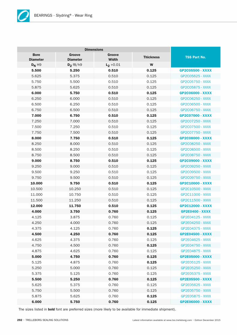
BEARINGS · Slydring® - Wear Ring
292 • TRELLEBORG SEALING SOLUTIONS Latest information available at www.tss.trelleborg.com • Edition December 2015
Dimensions
TSS Part no. Bore
Diameter Groove
Diameter Groove Width
Thickness
Dn H9 D2 f8/h9 L2 +0.01 W
5.500 5.250 0.510 0.125 GP2C05500 - xxxx
5.625 5.375 0.510 0.125 GP2C05625 - XXXX
5.750 5.500 0.510 0.125 GP2C05750 - XXXX
5.875 5.625 0.510 0.125 GP2C05875 - XXXX
6.000 5.750 0.510 0.125 GP2C06000 - xxxx
6.250 6.000 0.510 0.125 GP2C06250 - XXXX
6.500 6.250 0.510 0.125 GP2C06500 - XXXX
6.750 6.500 0.510 0.125 GP2C06750 - XXXX
7.000 6.750 0.510 0.125 GP2C07000 - xxxx
7.250 7.000 0.510 0.125 GP2C07250 - XXXX
7.500 7.250 0.510 0.125 GP2C07500 - XXXX
7.750 7.500 0.510 0.125 GP2C07750 - XXXX
8.000 7.750 0.510 0.125 GP2C08000 - xxxx
8.250 8.000 0.510 0.125 GP2C08250 - XXXX
8.500 8.250 0.510 0.125 GP2C08500 - XXXX
8.750 8.500 0.510 0.125 GP2C08750 - XXXX
9.000 8.750 0.510 0.125 GP2C09000 - xxxx
9.250 9.000 0.510 0.125 GP2C09250 - XXXX
9.500 9.250 0.510 0.125 GP2C09500 - XXXX
9.750 9.500 0.510 0.125 GP2C09750 - XXXX
10.000 9.750 0.510 0.125 GP2C10000 - xxxx
10.500 10.250 0.510 0.125 GP2C10500 - XXXX
11.000 10.750 0.510 0.125 GP2C11000 - XXXX
11.500 11.250 0.510 0.125 GP2C11500 - XXXX
12.000 11.750 0.510 0.125 GP2C12000 - xxxx
4.000 3.750 0.760 0.125 GP2E0400 - xxxx
4.125 3.875 0.760 0.125 GP2E04125 - XXXX
4.250 4.000 0.760 0.125 GP2E04250 - XXXX
4.375 4.125 0.760 0.125 GP2E04375 - XXXX
4.500 4.250 0.760 0.125 GP2E04500 - xxxx
4.625 4.375 0.760 0.125 GP2E04625 - XXXX
4.750 4.500 0.760 0.125 GP2E04750 - XXXX
4.875 4.625 0.760 0.125 GP2E04875 - XXXX
5.000 4.750 0.760 0.125 GP2E05000 - xxxx
5.125 4.875 0.760 0.125 GP2E05125 - XXXX
5.250 5.000 0.760 0.125 GP2E05250 - XXXX
5.375 5.125 0.760 0.125 GP2E05375 - XXXX
5.500 5.250 0.760 0.125 GP2E05500 - xxxx
5.625 5.375 0.760 0.125 GP2E05625 - XXXX
5.750 5.500 0.760 0.125 GP2E05750 - XXXX
5.875 5.625 0.760 0.125 GP2E05875 - XXXX
6.000 5.750 0.760 0.125 GP2E06000 - xxxx
The sizes listed in bold font are preferred sizes (more likely to be available for immediate shipment).
FBP_neues_Layout_2015.indb 292 17.10.2016 13:38:08
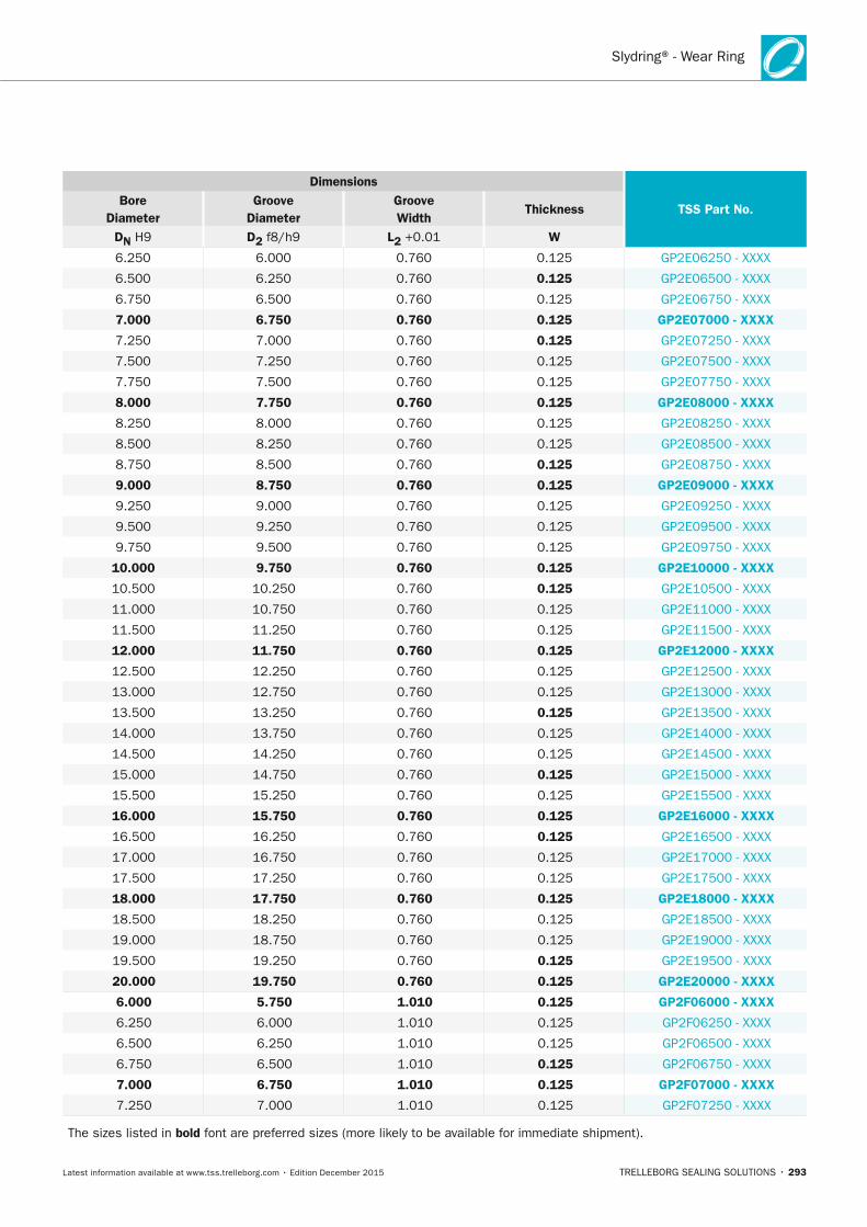
Slydring® - Wear Ring
TRELLEBORG SEALING SOLUTIONS • 293Latest information available at www.tss.trelleborg.com • Edition December 2015
Dimensions
TSS Part no. Bore
Diameter Groove
Diameter Groove Width
Thickness
Dn H9 D2 f8/h9 L2 +0.01 W
6.250 6.000 0.760 0.125 GP2E06250 - XXXX
6.500 6.250 0.760 0.125 GP2E06500 - XXXX
6.750 6.500 0.760 0.125 GP2E06750 - XXXX
7.000 6.750 0.760 0.125 GP2E07000 - xxxx
7.250 7.000 0.760 0.125 GP2E07250 - XXXX
7.500 7.250 0.760 0.125 GP2E07500 - XXXX
7.750 7.500 0.760 0.125 GP2E07750 - XXXX
8.000 7.750 0.760 0.125 GP2E08000 - xxxx
8.250 8.000 0.760 0.125 GP2E08250 - XXXX
8.500 8.250 0.760 0.125 GP2E08500 - XXXX
8.750 8.500 0.760 0.125 GP2E08750 - XXXX
9.000 8.750 0.760 0.125 GP2E09000 - xxxx
9.250 9.000 0.760 0.125 GP2E09250 - XXXX
9.500 9.250 0.760 0.125 GP2E09500 - XXXX
9.750 9.500 0.760 0.125 GP2E09750 - XXXX
10.000 9.750 0.760 0.125 GP2E10000 - xxxx
10.500 10.250 0.760 0.125 GP2E10500 - XXXX
11.000 10.750 0.760 0.125 GP2E11000 - XXXX
11.500 11.250 0.760 0.125 GP2E11500 - XXXX
12.000 11.750 0.760 0.125 GP2E12000 - xxxx
12.500 12.250 0.760 0.125 GP2E12500 - XXXX
13.000 12.750 0.760 0.125 GP2E13000 - XXXX
13.500 13.250 0.760 0.125 GP2E13500 - XXXX
14.000 13.750 0.760 0.125 GP2E14000 - XXXX
14.500 14.250 0.760 0.125 GP2E14500 - XXXX
15.000 14.750 0.760 0.125 GP2E15000 - XXXX
15.500 15.250 0.760 0.125 GP2E15500 - XXXX
16.000 15.750 0.760 0.125 GP2E16000 - xxxx
16.500 16.250 0.760 0.125 GP2E16500 - XXXX
17.000 16.750 0.760 0.125 GP2E17000 - XXXX
17.500 17.250 0.760 0.125 GP2E17500 - XXXX
18.000 17.750 0.760 0.125 GP2E18000 - xxxx
18.500 18.250 0.760 0.125 GP2E18500 - XXXX
19.000 18.750 0.760 0.125 GP2E19000 - XXXX
19.500 19.250 0.760 0.125 GP2E19500 - XXXX
20.000 19.750 0.760 0.125 GP2E20000 - xxxx
6.000 5.750 1.010 0.125 GP2F06000 - xxxx
6.250 6.000 1.010 0.125 GP2F06250 - XXXX
6.500 6.250 1.010 0.125 GP2F06500 - XXXX
6.750 6.500 1.010 0.125 GP2F06750 - XXXX
7.000 6.750 1.010 0.125 GP2F07000 - xxxx
7.250 7.000 1.010 0.125 GP2F07250 - XXXX
The sizes listed in bold font are preferred sizes (more likely to be available for immediate shipment).
FBP_neues_Layout_2015.indb 293 17.10.2016 13:38:08
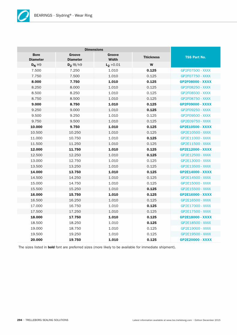
BEARINGS · Slydring® - Wear Ring
294 • TRELLEBORG SEALING SOLUTIONS Latest information available at www.tss.trelleborg.com • Edition December 2015
Dimensions
TSS Part no. Bore
Diameter Groove
Diameter Groove Width
Thickness
Dn H9 D2 f8/h9 L2 +0.01 W
7.500 7.250 1.010 0.125 GP2F07500 - XXXX
7.750 7.500 1.010 0.125 GP2F07750 - XXXX
8.000 7.750 1.010 0.125 GP2F08000 - xxxx
8.250 8.000 1.010 0.125 GP2F08250 - XXXX
8.500 8.250 1.010 0.125 GP2F08500 - XXXX
8.750 8.500 1.010 0.125 GP2F08750 - XXXX
9.000 8.750 1.010 0.125 GP2F09000 - xxxx
9.250 9.000 1.010 0.125 GP2F09250 - XXXX
9.500 9.250 1.010 0.125 GP2F09500 - XXXX
9.750 9.500 1.010 0.125 GP2E09750 - XXXX
10.000 9.750 1.010 0.125 GP2E10500 - xxxx
10.500 10.250 1.010 0.125 GP2E10500 - XXXX
11.000 10.750 1.010 0.125 GP2E11000 - XXXX
11.500 11.250 1.010 0.125 GP2E11500 - XXXX
12.000 11.750 1.010 0.125 GP2E12000 - xxxx
12.500 12.250 1.010 0.125 GP2E12500 - XXXX
13.000 12.750 1.010 0.125 GP2E13000 - XXXX
13.500 13.250 1.010 0.125 GP2E13500 - XXXX
14.000 13.750 1.010 0.125 GP2E14000 - xxxx
14.500 14.250 1.010 0.125 GP2E14500 - XXXX
15.000 14.750 1.010 0.125 GP2E15000 - XXXX
15.500 15.250 1.010 0.125 GP2E15500 - XXXX
16.000 15.750 1.010 0.125 GP2E16000 - xxxx
16.500 16.250 1.010 0.125 GP2E16500 - XXXX
17.000 16.750 1.010 0.125 GP2E17000 - XXXX
17.500 17.250 1.010 0.125 GP2E17500 - XXXX
18.000 17.750 1.010 0.125 GP2E18000 - xxxx
18.500 18.250 1.010 0.125 GP2E18500 - XXXX
19.000 18.750 1.010 0.125 GP2E19000 - XXXX
19.500 19.250 1.010 0.125 GP2E19500 - XXXX
20.000 19.750 1.010 0.125 GP2E20000 - xxxx
The sizes listed in bold font are preferred sizes (more likely to be available for immediate shipment).
FBP_neues_Layout_2015.indb 294 17.10.2016 13:38:08

Slydring® - Wear Ring
TRELLEBORG SEALING SOLUTIONS • 295Latest information available at www.tss.trelleborg.com • Edition December 2015
FBP_neues_Layout_2015.indb 295 17.10.2016 13:38:08
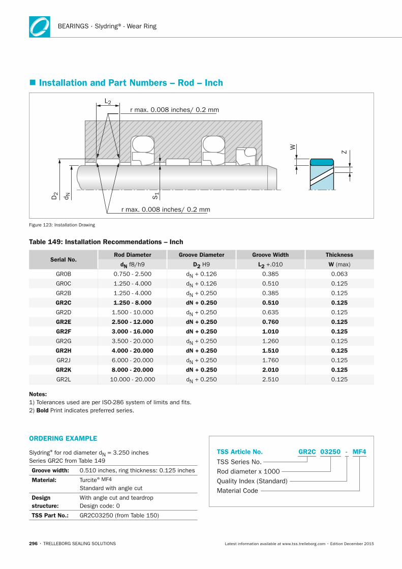
BEARINGS · Slydring® - Wear Ring
296 • TRELLEBORG SEALING SOLUTIONS Latest information available at www.tss.trelleborg.com • Edition December 2015
� Installation and Part numbers – Rod – Inch
r max. 0.008 inches/ 0.2 mm
r max. 0.008 inches/ 0.2 mm
L2
S1
D2
d N
W
Z
Figure 123: Installation Drawing
Table 149: Installation Recommendations – Inch
Serial no.Rod Diameter Groove Diameter Groove Width Thickness
dn f8/h9 D2 H9 L2 +.010 W (max)
GR0B 0.750 - 2.500 dN + 0.126 0.385 0.063
GR0C 1.250 - 4.000 dN + 0.126 0.510 0.125
GR2B 1.250 - 4.000 dN + 0.250 0.385 0.125
GR2C 1.250 - 8.000 dn + 0.250 0.510 0.125
GR2D 1.500 - 10.000 dN + 0.250 0.635 0.125
GR2E 2.500 - 12.000 dn + 0.250 0.760 0.125
GR2F 3.000 - 16.000 dn + 0.250 1.010 0.125
GR2G 3.500 - 20.000 dN + 0.250 1.260 0.125
GR2H 4.000 - 20.000 dn + 0.250 1.510 0.125
GR2J 6.000 - 20.000 dN + 0.250 1.760 0.125
GR2K 8.000 - 20.000 dn + 0.250 2.010 0.125
GR2L 10.000 - 20.000 dN + 0.250 2.510 0.125
notes:1) Tolerances used are per ISO-286 system of limits and fits.2) Bold Print indicates preferred series.
ORDERInG ExAMPLE
Slydring® for rod diameter dN = 3.250 inches Series GR2C from Table 149
Groove width: 0.510 inches, ring thickness: 0.125 inches
Material: Turcite® MF4 Standard with angle cut
Design structure:
With angle cut and teardrop Design code: 0
TSS Part no.: GR2C03250 (from Table 150)
TSS Series No.
TSS Article No.
Quality Index (Standard)Material Code
Rod diameter x 1000
MF4GR2C -03250
FBP_neues_Layout_2015.indb 296 17.10.2016 13:38:09
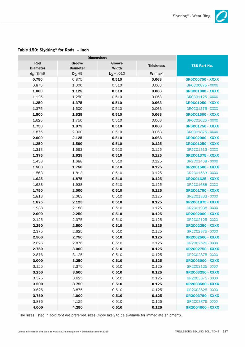
Slydring® - Wear Ring
TRELLEBORG SEALING SOLUTIONS • 297Latest information available at www.tss.trelleborg.com • Edition December 2015
Table 150: Slydring® for Rods – Inch
Dimensions
TSS Part no. Rod
Diameter Groove
Diameter Groove Width
Thickness
dn f8/h9 D2 H9 L2 + .010 W (max)
0.750 0.875 0.510 0.063 GR0C00750 - xxxx
0.875 1.000 0.510 0.063 GR0C00875 - XXXX
1.000 1.125 0.510 0.063 GR0C01000 - xxxx
1.125 1.250 0.510 0.063 GR0C01125 - XXXX
1.250 1.375 0.510 0.063 GR0C01250 - xxxx
1.375 1.500 0.510 0.063 GR0C01375 - XXXX
1.500 1.625 0.510 0.063 GR0C01500 - xxxx
1.625 1.750 0.510 0.063 GR0C01625 - XXXX
1.750 1.875 0.510 0.063 GR0C01750 - xxxx
1.875 2.000 0.510 0.063 GR0C01875 - XXXX
2.000 2.125 0.510 0.063 GR0C02000 - xxxx
1.250 1.500 0.510 0.125 GR2C01250 - xxxx
1.313 1.563 0.510 0.125 GR2C01313 - XXXX
1.375 1.625 0.510 0.125 GR2C01375 - xxxx
1.438 1.688 0.510 0.125 GR2C01438 - XXXX
1.500 1.750 0.510 0.125 GR2C01500 - xxxx
1.563 1.813 0.510 0.125 GR2C01563 - XXXX
1.625 1.875 0.510 0.125 GR2C01625 - xxxx
1.688 1.938 0.510 0.125 GR2C01688 - XXXX
1.750 2.000 0.510 0.125 GR2C01750 - xxxx
1.813 2.063 0.510 0.125 GR2C01833 - XXXX
1.875 2.125 0.510 0.125 GR2C01875 - xxxx
1.938 2.188 0.510 0.125 GR2C01938 - XXXX
2.000 2.250 0.510 0.125 GR2C02000 - xxxx
2.125 2.375 0.510 0.125 GR2C02125 - XXXX
2.250 2.500 0.510 0.125 GR2C02250 - xxxx
2.375 2.625 0.510 0.125 GR2C02375 - XXXX
2.500 2.750 0.510 0.125 GR2C02500 - xxxx
2.626 2.876 0.510 0.125 GR2C02626 - XXXX
2.750 3.000 0.510 0.125 GR2C02750 - xxxx
2.876 3.125 0.510 0.125 GR2C02875 - XXXX
3.000 3.250 0.510 0.125 GR2C03000 - xxxx
3.125 3.375 0.510 0.125 GR2C03125 - XXXX
3.250 3.500 0.510 0.125 GR2C03250 - xxxx
3.375 3.625 0.510 0.125 GR2C03375 - XXXX
3.500 3.750 0.510 0.125 GR2C03500 - xxxx
3.625 3.875 0.510 0.125 GR2C03625 - XXXX
3.750 4.000 0.510 0.125 GR2C03750 - xxxx
3.875 4.125 0.510 0.125 GR2C03875 - XXXX
4.000 4.250 0.510 0.125 GR2C04000 - xxxx
The sizes listed in bold font are preferred sizes (more likely to be available for immediate shipment).
FBP_neues_Layout_2015.indb 297 17.10.2016 13:38:09
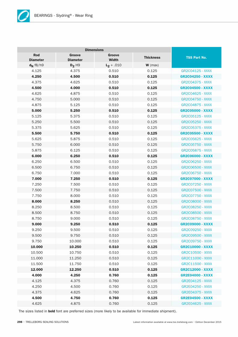
BEARINGS · Slydring® - Wear Ring
298 • TRELLEBORG SEALING SOLUTIONS Latest information available at www.tss.trelleborg.com • Edition December 2015
Dimensions
TSS Part no. Rod
Diameter Groove
Diameter Groove Width
Thickness
dn f8/h9 D2 H9 L2 + .010 W (max)
4.125 4.375 0.510 0.125 GR2C04125 - XXXX
4.250 4.500 0.510 0.125 GR2C04250 - xxxx
4.375 4.625 0.510 0.125 GR2C04375 - XXXX
4.500 4.000 0.510 0.125 GR2C04500 - xxxx
4.625 4.875 0.510 0.125 GR2C04625 - XXXX
4.750 5.000 0.510 0.125 GR2C04750 - XXXX
4.875 5.125 0.510 0.125 GR2C04875 - XXXX
5.000 5.250 0.510 0.125 GR2C05000 - xxxx
5.125 5.375 0.510 0.125 GR2C05125 - XXXX
5.250 5.500 0.510 0.125 GR2C05250 - XXXX
5.375 5.625 0.510 0.125 GR2C05375 - XXXX
5.500 5.750 0.510 0.125 GR2C05500 - xxxx
5.625 5.875 0.510 0.125 GR2C05625 - XXXX
5.750 6.000 0.510 0.125 GR2C05750 - XXXX
5.875 6.125 0.510 0.125 GR2C05875 - XXXX
6.000 6.250 0.510 0.125 GR2C06000 - xxxx
6.250 6.500 0.510 0.125 GR2C06250 - XXXX
6.500 6.750 0.510 0.125 GR2C06500 - XXXX
6.750 7.000 0.510 0.125 GR2C06750 - XXXX
7.000 7.250 0.510 0.125 GR2C07000 - xxxx
7.250 7.500 0.510 0.125 GR2C07250 - XXXX
7.500 7.750 0.510 0.125 GR2C07500 - XXXX
7.750 8.000 0.510 0.125 GR2C07750 - XXXX
8.000 8.250 0.510 0.125 GR2C08000 - XXXX
8.250 8.500 0.510 0.125 GR2C08250 - XXXX
8.500 8.750 0.510 0.125 GR2C08500 - XXXX
8.750 9.000 0.510 0.125 GR2C08750 - XXXX
9.000 9.250 0.510 0.125 GR2C09000 - xxxx
9.250 9.500 0.510 0.125 GR2C09250 - XXXX
9.500 9.750 0.510 0.125 GR2C09500 - XXXX
9.750 10.000 0.510 0.125 GR2C09750 - XXXX
10.000 10.250 0.510 0.125 GR2C10000 - xxxx
10.500 10.750 0.510 0.125 GR2C10500 - XXXX
11.000 11.250 0.510 0.125 GR2C11000 - XXXX
11.500 11.750 0.510 0.125 GR2C11500 - XXXX
12.000 12.250 0.510 0.125 GR2C12000 - xxxx
4.000 4.250 0.760 0.125 GR2E04000 - xxxx
4.125 4.375 0.760 0.125 GR2E04125 - XXXX
4.250 4.500 0.760 0.125 GR2E04250 - XXXX
4.375 4.625 0.760 0.125 GR2E04375 - XXXX
4.500 4.750 0.760 0.125 GR2E04500 - xxxx
4.625 4.875 0.760 0.125 GR2E04625 - XXXX
The sizes listed in bold font are preferred sizes (more likely to be available for immediate shipment).
FBP_neues_Layout_2015.indb 298 17.10.2016 13:38:10
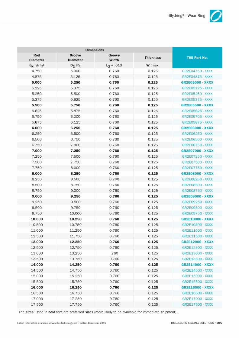
Slydring® - Wear Ring
TRELLEBORG SEALING SOLUTIONS • 299Latest information available at www.tss.trelleborg.com • Edition December 2015
Dimensions
TSS Part no. Rod
Diameter Groove
Diameter Groove Width
Thickness
dn f8/h9 D2 H9 L2 + .010 W (max)
4.750 5.000 0.760 0.125 GR2E04750 - XXXX
4.875 5.125 0.760 0.125 GR2E04875 - XXXX
5.000 5.250 0.760 0.125 GR2E05000 - xxxx
5.125 5.375 0.760 0.125 GR2E05125 - XXXX
5.250 5.500 0.760 0.125 GR2E05250 - XXXX
5.375 5.625 0.760 0.125 GR2E05375 - XXXX
5.500 5.750 0.760 0.125 GR2E05500 - xxxx
5.625 5.875 0.760 0.125 GR2E05625 - XXXX
5.750 6.000 0.760 0.125 GR2E05705 - XXXX
5.875 6.125 0.760 0.125 GR2E05875 - XXXX
6.000 6.250 0.760 0.125 GR2E06000 - xxxx
6.250 6.500 0.760 0.125 GR2E06250 - XXXX
6.500 6.750 0.760 0.125 GR2E06500 - XXXX
6.750 7.000 0.760 0.125 GR2E06750 - XXXX
7.000 7.250 0.760 0.125 GR2E07000 - xxxx
7.250 7.500 0.760 0.125 GR2E07250 - XXXX
7.500 7.750 0.760 0.125 GR2E07500 - XXXX
7.750 8.000 0.760 0.125 GR2E07750 - XXXX
8.000 8.250 0.760 0.125 GR2E08000 - xxxx
8.250 8.500 0.760 0.125 GR2E08250 - XXXX
8.500 8.750 0.760 0.125 GR2E08500 - XXXX
8.750 9.000 0.760 0.125 GR2E08750 - XXXX
9.000 9.250 0.760 0.125 GR2E09000 - xxxx
9.250 9.500 0.760 0.125 GR2E09250 - XXXX
9.500 9.750 0.760 0.125 GR2E09500 - XXXX
9.750 10.000 0.760 0.125 GR2E09750 - XXXX
10.000 10.250 0.760 0.125 GR2E10000 - xxxx
10.500 10.750 0.760 0.125 GR2E10500 - XXXX
11.000 11.250 0.760 0.125 GR2E11000 - XXXX
11.500 11.750 0.760 0.125 GR2E11500 - XXXX
12.000 12.250 0.760 0.125 GR2E12000 - xxxx
12.500 12.750 0.760 0.125 GR2E12500 - XXXX
13.000 13.250 .760 0.125 GR2E13000 - XXXX
13.500 13.750 0.760 0.125 GR2E13500 - XXXX
14.000 14.250 0.760 0.125 GR2E14000 - xxxx
14.500 14.750 0.760 0.125 GR2E14500 - XXXX
15.000 15.250 0.760 0.125 GR2E15000 - XXXX
15.500 15.750 0.760 0.125 GR2E15500 - XXXX
16.000 16.250 0.760 0.125 GR2E16000 - xxxx
16.500 16.750 0.760 0.125 GR2E16500 - XXXX
17.000 17.250 0.760 0.125 GR2E17000 - XXXX
17.500 17.750 0.760 0.125 GR2E17500 - XXXX
The sizes listed in bold font are preferred sizes (more likely to be available for immediate shipment).
FBP_neues_Layout_2015.indb 299 17.10.2016 13:38:10
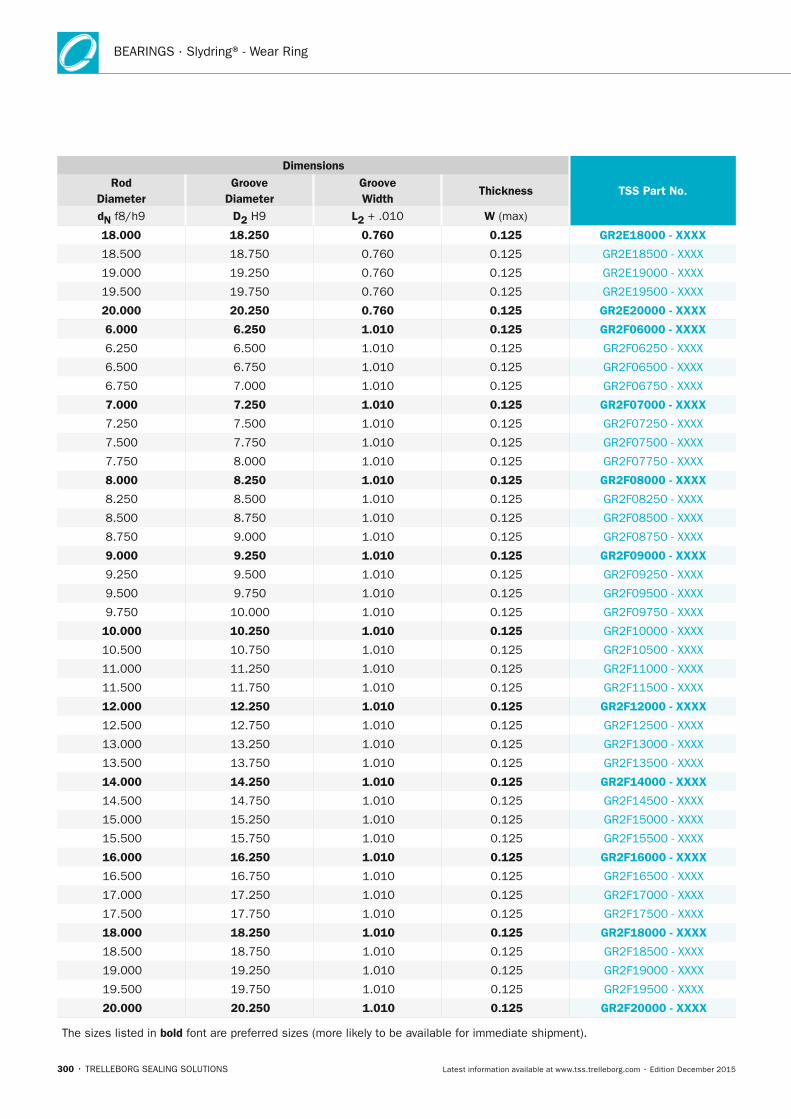
BEARINGS · Slydring® - Wear Ring
300 • TRELLEBORG SEALING SOLUTIONS Latest information available at www.tss.trelleborg.com • Edition December 2015
Dimensions
TSS Part no. Rod
Diameter Groove
Diameter Groove Width
Thickness
dn f8/h9 D2 H9 L2 + .010 W (max)
18.000 18.250 0.760 0.125 GR2E18000 - xxxx
18.500 18.750 0.760 0.125 GR2E18500 - XXXX
19.000 19.250 0.760 0.125 GR2E19000 - XXXX
19.500 19.750 0.760 0.125 GR2E19500 - XXXX
20.000 20.250 0.760 0.125 GR2E20000 - xxxx
6.000 6.250 1.010 0.125 GR2F06000 - xxxx
6.250 6.500 1.010 0.125 GR2F06250 - XXXX
6.500 6.750 1.010 0.125 GR2F06500 - XXXX
6.750 7.000 1.010 0.125 GR2F06750 - XXXX
7.000 7.250 1.010 0.125 GR2F07000 - xxxx
7.250 7.500 1.010 0.125 GR2F07250 - XXXX
7.500 7.750 1.010 0.125 GR2F07500 - XXXX
7.750 8.000 1.010 0.125 GR2F07750 - XXXX
8.000 8.250 1.010 0.125 GR2F08000 - xxxx
8.250 8.500 1.010 0.125 GR2F08250 - XXXX
8.500 8.750 1.010 0.125 GR2F08500 - XXXX
8.750 9.000 1.010 0.125 GR2F08750 - XXXX
9.000 9.250 1.010 0.125 GR2F09000 - xxxx
9.250 9.500 1.010 0.125 GR2F09250 - XXXX
9.500 9.750 1.010 0.125 GR2F09500 - XXXX
9.750 10.000 1.010 0.125 GR2F09750 - XXXX
10.000 10.250 1.010 0.125 GR2F10000 - XXXX
10.500 10.750 1.010 0.125 GR2F10500 - XXXX
11.000 11.250 1.010 0.125 GR2F11000 - XXXX
11.500 11.750 1.010 0.125 GR2F11500 - XXXX
12.000 12.250 1.010 0.125 GR2F12000 - xxxx
12.500 12.750 1.010 0.125 GR2F12500 - XXXX
13.000 13.250 1.010 0.125 GR2F13000 - XXXX
13.500 13.750 1.010 0.125 GR2F13500 - XXXX
14.000 14.250 1.010 0.125 GR2F14000 - xxxx
14.500 14.750 1.010 0.125 GR2F14500 - XXXX
15.000 15.250 1.010 0.125 GR2F15000 - XXXX
15.500 15.750 1.010 0.125 GR2F15500 - XXXX
16.000 16.250 1.010 0.125 GR2F16000 - xxxx
16.500 16.750 1.010 0.125 GR2F16500 - XXXX
17.000 17.250 1.010 0.125 GR2F17000 - XXXX
17.500 17.750 1.010 0.125 GR2F17500 - XXXX
18.000 18.250 1.010 0.125 GR2F18000 - xxxx
18.500 18.750 1.010 0.125 GR2F18500 - XXXX
19.000 19.250 1.010 0.125 GR2F19000 - XXXX
19.500 19.750 1.010 0.125 GR2F19500 - XXXX
20.000 20.250 1.010 0.125 GR2F20000 - xxxx
The sizes listed in bold font are preferred sizes (more likely to be available for immediate shipment).
FBP_neues_Layout_2015.indb 300 17.10.2016 13:38:10
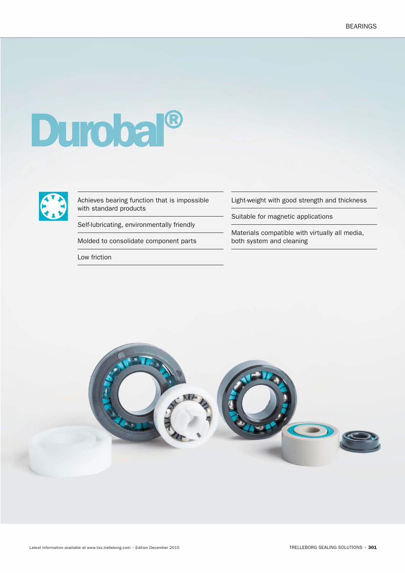
BEARINGS
TRELLEBORG SEALING SOLUTIONS • 301Latest information available at www.tss.trelleborg.com • Edition December 2015
Durobal®Achieves bearing function that is impossible with standard products
Self-lubricating, environmentally friendly
Molded to consolidate component parts
Low friction
Light-weight with good strength and thickness
Suitable for magnetic applications
Materials compatible with virtually all media, both system and cleaning
FBP_neues_Layout_2015.indb 301 17.10.2016 13:38:12

BEARINGS · Durobal®
302 • TRELLEBORG SEALING SOLUTIONS Latest information available at www.tss.trelleborg.com • Edition December 2015
FBP_neues_Layout_2015.indb 302 17.10.2016 13:38:12
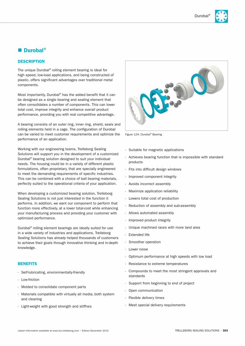
Durobal®
TRELLEBORG SEALING SOLUTIONS • 303Latest information available at www.tss.trelleborg.com • Edition December 2015
� Durobal®
DESCRIPTIOn
The unique Durobal® rolling element bearing is ideal for high speed, low-load applications, and being constructed of plastic, offers significant advantages over traditional metal components.
Most importantly, Durobal® has the added benefit that it can be designed as a single bearing and sealing element that often consolidates a number of components. This can lower total cost, improve integrity and enhance overall product performance, providing you with real competitive advantage.
A bearing consists of an outer ring, inner ring, shield, seals and rolling elements held in a cage. The configuration of Durobal can be varied to meet customer requirements and optimize the performance of an application.
Working with our engineering teams, Trelleborg Sealing Solutions will support you in the development of a customized Durobal® bearing solution designed to suit your individual needs. The housing could be in a variety of different plastic formulations, often proprietary, that are specially engineered to meet the demanding requirements of specific industries. This can be combined with a choice of ball bearing materials, perfectly suited to the operational criteria of your application.
When developing a customized bearing solution, Trelleborg Sealing Solutions is not just interested in the function it performs. In addition, we want our component to perform that function more effectively, at a lower total-cost while enhancing your manufacturing process and providing your customer with optimized performance.
Durobal® rolling element bearings are ideally suited for use in a wide variety of industries and applications. Trelleborg Sealing Solutions has already helped thousands of customers to achieve their goals through innovative thinking and in-depth knowledge.
BEnEFITS
- Self-lubricating, environmentally-friendly
- Low-friction
- Molded to consolidate component parts
- Materials compatible with virtually all media, both system and cleaning
- Light-weight with good strength and stiffnes
-
-
-
-
-
-
-
-
Figure 124: Durobal® Bearing
- Suitable for magnetic applications
- Achieves bearing function that is impossible with standard products
- Fits into difficult design windows
- Improved component integrity
- Avoids incorrect assembly
- Maximize application reliability
- Lowers total cost of production
- Reduction of assembly and sub-assembly
- Allows automated assembly
- Improved product integrity
- Unique machined races with more land area
- Extended life
- Smoother operation
- Lower noise
- Optimum performance at high speeds with low load
- Resistance to extreme temperatures
- Compounds to meet the most stringent approvals and standards
- Support from beginning to end of project
- Open communication
- Flexible delivery times
- Meet special delivery requirements
FBP_neues_Layout_2015.indb 303 17.10.2016 13:38:13
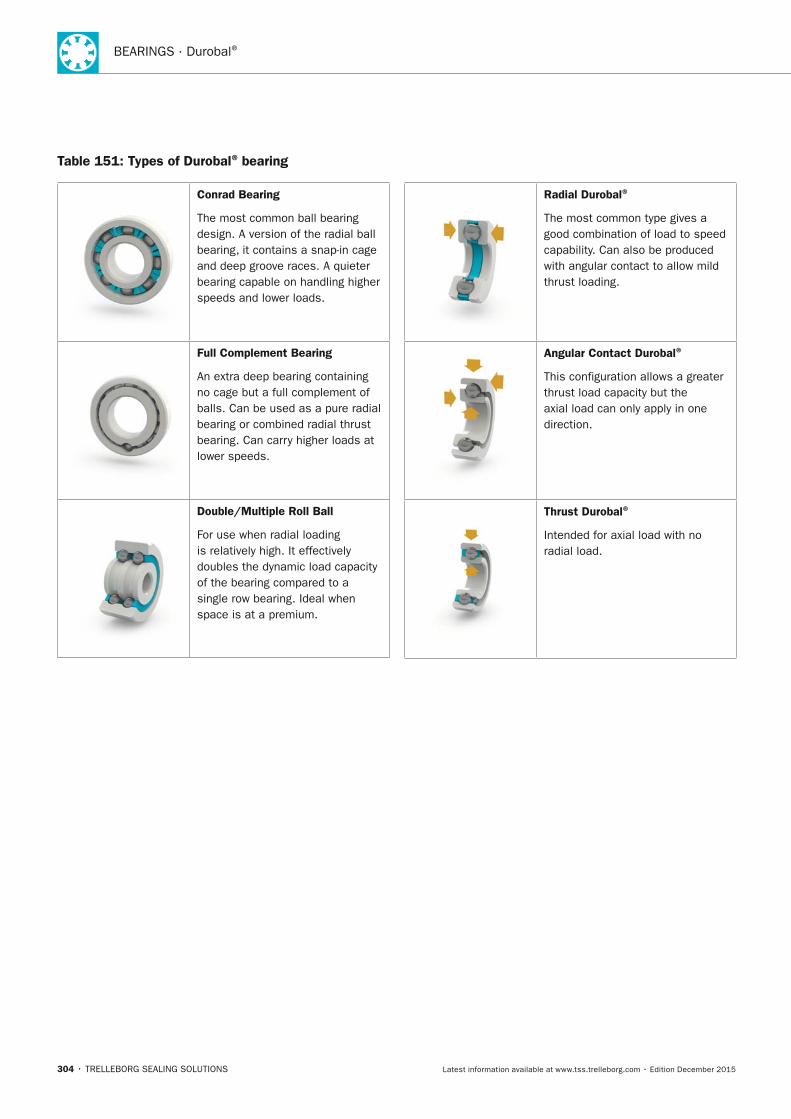
BEARINGS · Durobal®
304 • TRELLEBORG SEALING SOLUTIONS Latest information available at www.tss.trelleborg.com • Edition December 2015
Table 151: Types of Durobal® bearing
Conrad Bearing
The most common ball bearing design. A version of the radial ball bearing, it contains a snap-in cage and deep groove races. A quieter bearing capable on handling higher speeds and lower loads.
Full Complement Bearing
An extra deep bearing containing no cage but a full complement of balls. Can be used as a pure radial bearing or combined radial thrust bearing. Can carry higher loads at lower speeds.
Double/Multiple Roll Ball
For use when radial loading is relatively high. It effectively doubles the dynamic load capacity of the bearing compared to a single row bearing. Ideal when space is at a premium.
Radial Durobal®
The most common type gives a good combination of load to speed capability. Can also be produced with angular contact to allow mild thrust loading.
Angular Contact Durobal®
This configuration allows a greater thrust load capacity but the axial load can only apply in one direction.
Thrust Durobal®
Intended for axial load with no radial load.
FBP_neues_Layout_2015.indb 304 17.10.2016 13:38:18
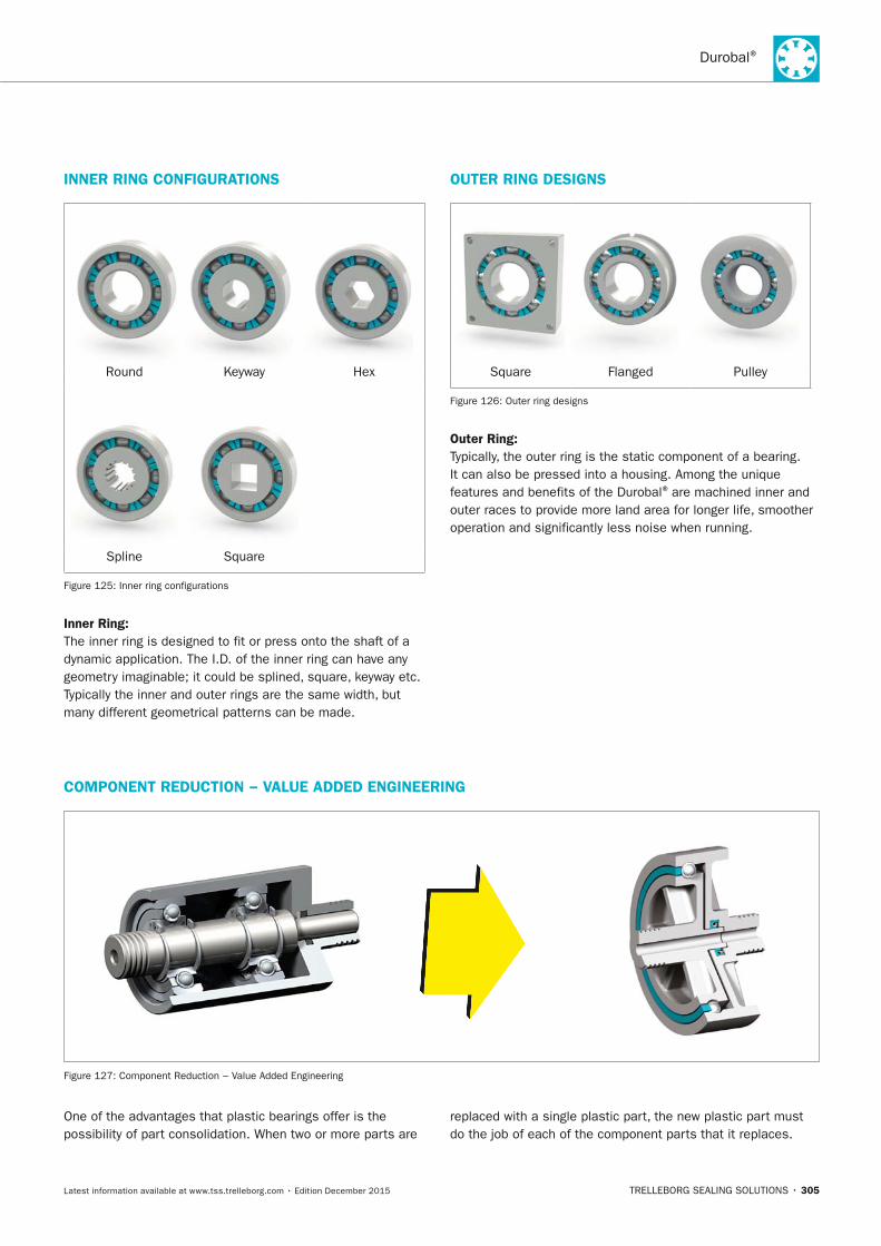
Durobal®
TRELLEBORG SEALING SOLUTIONS • 305Latest information available at www.tss.trelleborg.com • Edition December 2015
One of the advantages that plastic bearings offer is the possibility of part consolidation. When two or more parts are
replaced with a single plastic part, the new plastic part must do the job of each of the component parts that it replaces.
InnER RInG COnFIGURATIOnS
Round Keyway Hex
Spline Square
Figure 125: Inner ring configurations
Inner Ring:The inner ring is designed to fit or press onto the shaft of a dynamic application. The I.D. of the inner ring can have any geometry imaginable; it could be splined, square, keyway etc. Typically the inner and outer rings are the same width, but many different geometrical patterns can be made.
COMPOnEnT REDUCTIOn − VALUE ADDED EnGInEERInG
Figure 127: Component Reduction − Value Added Engineering
OUTER RInG DESIGnS
Square Flanged Pulley
Figure 126: Outer ring designs
Outer Ring: Typically, the outer ring is the static component of a bearing. It can also be pressed into a housing. Among the unique features and benefits of the Durobal® are machined inner and outer races to provide more land area for longer life, smoother operation and significantly less noise when running.
FBP_neues_Layout_2015.indb 305 17.10.2016 13:38:25

BEARINGS · Durobal®
306 • TRELLEBORG SEALING SOLUTIONS Latest information available at www.tss.trelleborg.com • Edition December 2015
FBP_neues_Layout_2015.indb 306 17.10.2016 13:38:25
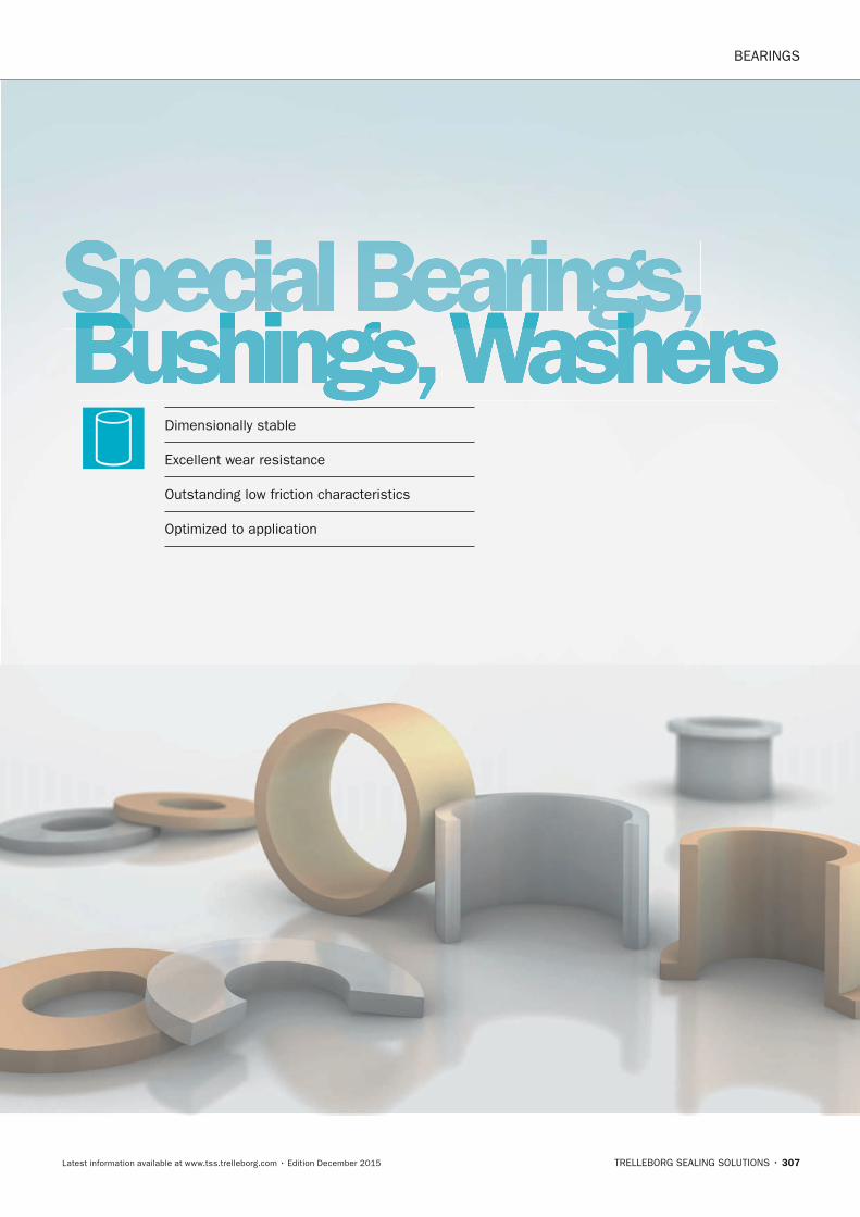
BEARINGS
TRELLEBORG SEALING SOLUTIONS • 307Latest information available at www.tss.trelleborg.com • Edition December 2015
Special Bearings,Bushings, WashersSpecial Bearings,Bushings, WashersSpecial Bearings,
Dimensionally stable
Excellent wear resistance
Outstanding low friction characteristics
Optimized to application
FBP_neues_Layout_2015.indb 307 17.10.2016 13:38:31

BEARINGS · Special Bearings, Bushings and Washers
308 • TRELLEBORG SEALING SOLUTIONS Latest information available at www.tss.trelleborg.com • Edition December 2015
FBP_neues_Layout_2015.indb 308 17.10.2016 13:38:31
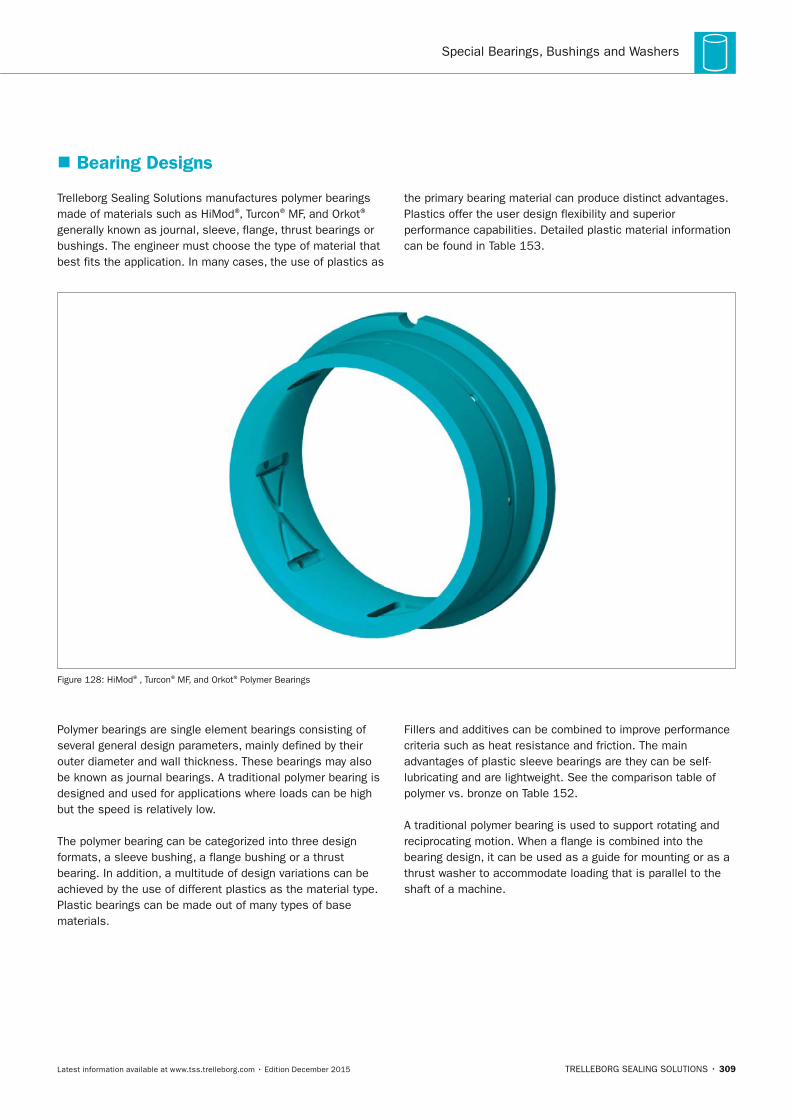
Special Bearings, Bushings and Washers
TRELLEBORG SEALING SOLUTIONS • 309Latest information available at www.tss.trelleborg.com • Edition December 2015
� Bearing Designs
Trelleborg Sealing Solutions manufactures polymer bearings made of materials such as HiMod®, Turcon® MF, and Orkot®
generally known as journal, sleeve, flange, thrust bearings or bushings. The engineer must choose the type of material that best fits the application. In many cases, the use of plastics as
the primary bearing material can produce distinct advantages. Plastics offer the user design flexibility and superior performance capabilities. Detailed plastic material information can be found in Table 153.
Figure 128: HiMod®, Turcon® MF, and Orkot® Polymer Bearings
Polymer bearings are single element bearings consisting of several general design parameters, mainly defined by their outer diameter and wall thickness. These bearings may also be known as journal bearings. A traditional polymer bearing is designed and used for applications where loads can be high but the speed is relatively low.
The polymer bearing can be categorized into three design formats, a sleeve bushing, a flange bushing or a thrust bearing. In addition, a multitude of design variations can be achieved by the use of different plastics as the material type. Plastic bearings can be made out of many types of base materials.
Fillers and additives can be combined to improve performance criteria such as heat resistance and friction. The main advantages of plastic sleeve bearings are they can be self-lubricating and are lightweight. See the comparison table of polymer vs. bronze on Table 152.
A traditional polymer bearing is used to support rotating and reciprocating motion. When a flange is combined into the bearing design, it can be used as a guide for mounting or as a thrust washer to accommodate loading that is parallel to the shaft of a machine.
FBP_neues_Layout_2015.indb 309 17.10.2016 13:38:32
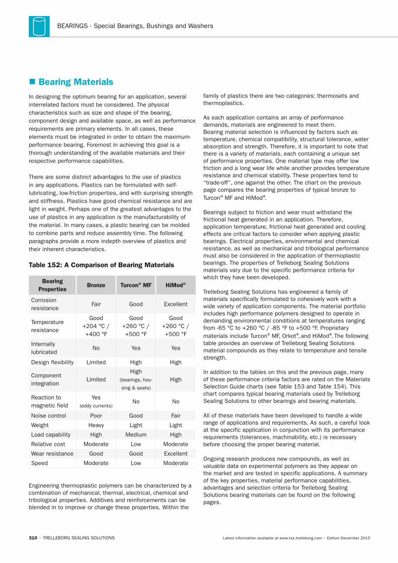
BEARINGS · Special Bearings, Bushings and Washers
310 • TRELLEBORG SEALING SOLUTIONS Latest information available at www.tss.trelleborg.com • Edition December 2015
� Bearing MaterialsIn designing the optimum bearing for an application, several interrelated factors must be considered. The physical characteristics such as size and shape of the bearing, component design and available space, as well as performance requirements are primary elements. In all cases, these elements must be integrated in order to obtain the maximum-performance bearing. Foremost in achieving this goal is a thorough understanding of the available materials and their respective performance capabilities.
There are some distinct advantages to the use of plastics in any applications. Plastics can be formulated with self-lubricating, low-friction properties, and with surprising strength and stiffness. Plastics have good chemical resistance and are light in weight. Perhaps one of the greatest advantages to the use of plastics in any application is the manufacturability of the material. In many cases, a plastic bearing can be molded to combine parts and reduce assembly time. The following paragraphs provide a more indepth overview of plastics and their inherent characteristics.
Table 152: A Comparison of Bearing Materials
Bearing Properties
Bronze Turcon® MF HiMod®
Corrosion resistance
Fair Good Excellent
Temperature resistance
Good +204 °C / +400 °F
Good +260 °C / +500 °F
Good +260 °C / +500 °F
Internally lubricated
No Yes Yes
Design flexibility Limited High High
Component integration
LimitedHigh
(bearings, hou-
sing & seats)
High
Reaction to magnetic field
Yes (eddy currents)
No No
Noise control Poor Good Fair
Weight Heavy Light Light
Load capability High Medium High
Relative cost Moderate Low Moderate
Wear resistance Good Good Excellent
Speed Moderate Low Moderate
Engineering thermoplastic polymers can be characterized by a combination of mechanical, thermal, electrical, chemical and tribological properties. Additives and reinforcements can be blended in to improve or change these properties. Within the
family of plastics there are two categories: thermosets and thermoplastics.
As each application contains an array of performance demands, materials are engineered to meet them. Bearing material selection is influenced by factors such as temperature, chemical compatibility, structural tolerance, water absorption and strength. Therefore, it is important to note that there is a variety of materials, each containing a unique set of performance properties. One material type may offer low friction and a long wear life while another provides temperature resistance and chemical stability. These properties tend to “trade-off”, one against the other. The chart on the previous page compares the bearing properties of typical bronze to Turcon® MF and HiMod®.
Bearings subject to friction and wear must withstand the frictional heat generated in an application. Therefore, application temperature, frictional heat generated and cooling effects are critical factors to consider when applying plastic bearings. Electrical properties, environmental and chemical resistance, as well as mechanical and tribological performance must also be considered in the application of thermoplastic bearings. The properties of Trelleborg Sealing Solutions materials vary due to the specific performance criteria for which they have been developed.
Trelleborg Sealing Solutions has engineered a family of materials specifically formulated to cohesively work with a wide variety of application components. The material portfolio includes high performance polymers designed to operate in demanding environmental conditions at temperatures ranging from -65 °C to +260 °C / -85 °F to +500 °F. Proprietary materials include Turcon® MF, Orkot®, and HiMod®. The following table provides an overview of Trelleborg Sealing Solutions material compounds as they relate to temperature and tensile strength.
In addition to the tables on this and the previous page, many of these performance criteria factors are rated on the Materials Selection Guide charts (see Table 153 and Table 154). This chart compares typical bearing materials used by Trelleborg Sealing Solutions to other bearings and bearing materials.
All of these materials have been developed to handle a wide range of applications and requirements. As such, a careful look at the specific application in conjunction with its performance requirements (tolerances, machinability, etc.) is necessary before choosing the proper bearing material.
Ongoing research produces new compounds, as well as valuable data on experimental polymers as they appear on the market and are tested in specific applications. A summary of the key properties, material performance capabilities, advantages and selection criteria for Trelleborg Sealing Solutions bearing materials can be found on the following pages.
FBP_neues_Layout_2015.indb 310 17.10.2016 13:38:32
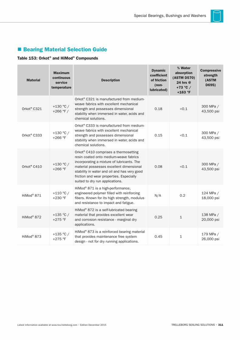
Special Bearings, Bushings and Washers
TRELLEBORG SEALING SOLUTIONS • 311Latest information available at www.tss.trelleborg.com • Edition December 2015
� Bearing Material Selection GuideTable 153: Orkot® and HiMod® Compounds
Material
Maximum continuous
service temperature
Description
Dynamic coefficient of friction
(non-lubricated)
% Water absorption
(ASTM D570) 24 hrs @ +73 °C / +163 °F
Compressive strength (ASTM D695)
Orkot® C321+130 °C / +266 °F /
Orkot® C321 is manufactured from medium-weave fabrics with excellent mechanical strength and possesses dimensional stability when immersed in water, acids and chemical solutions.
0.18 <0.1300 MPa / 43,500 psi
Orkot® C333+130 °C / +266 °F
Orkot® C333 is manufactured from medium-weave fabrics with excellent mechanical strength and possesses dimensional stability when immersed in water, acids and chemical solutions.
0.15 <0.1300 MPa / 43,500 psi
Orkot® C410+130 °C / +266 °F
Orkot® C410 comprises a thermosetting resin coated onto medium-weave fabrics incorporating a mixture of lubricants. The material possesses excellent dimensional stability in water and oil and has very good friction and wear properties. Especially suited to dry run applications.
0.08 <0.1300 MPa / 43,500 psi
HiMod® 871+110 °C / +230 °F
HiMod® 871 is a high-performance, engineered polymer filled with reinforcing fibers. Known for its high strength, modulus and resistance to impact and fatigue.
N/A 0.2124 MPa / 18,000 psi
HiMod® 872+135 °C / +275 °F
HiMod® 872 is a self-lubricated bearing material that provides excellent wear and corrosion resistance - marginal dry applications.
0.25 1138 MPa / 20,000 psi
HiMod® 873+135 °C / +275 °F
HiMod® 873 is a reinforced bearing material that provides maintenance free system design - not for dry running applications.
0.45 1179 MPa / 26,000 psi
FBP_neues_Layout_2015.indb 311 17.10.2016 13:38:32
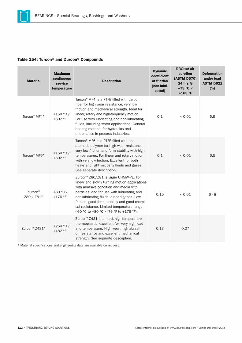
BEARINGS · Special Bearings, Bushings and Washers
312 • TRELLEBORG SEALING SOLUTIONS Latest information available at www.tss.trelleborg.com • Edition December 2015
Table 154: Turcon® and Zurcon® Compounds
Material
Maximum continuous
service temperature
Description
Dynamic coefficient of friction (non-lubri-
cated)
% Water ab-sorption
(ASTM D570) 24 hrs @ +73 °C / +163 °F
Deformation under load
ASTM D621 (%)
Turcon® MF4* +150 °C / +302 °F
Turcon® MF4 is a PTFE filled with carbon fiber for high wear resistance, very low friction and mechanical strength. Ideal for linear, rotary and high-frequency motion. For use with lubricating and non-lubricating fluids, including water applications. General bearing material for hydraulics and pneumatics in process industries.
0.1 < 0.01 5.9
Turcon® MF6* +150 °C / +302 °F
Turcon® MF6 is a PTFE filled with an aromatic polymer for high wear resistance, very low friction and form stability with high temperatures. For linear and rotary motion with very low friction. Excellent for both heavy and light viscosity fluids and gases. See separate description.
0.1 < 0.01 6.5
Zurcon® Z80 / Z81*
+80 °C / +176 °F
Zurcon® Z80/Z81 is virgin UHMW-PE. For linear and slowly turning motion applications with abrasive condition and media with particles, and for use with lubricating and non-lubricating fluids, air and gases. Low friction, good form stability and good chemi-cal resistance. Limited temperature range. (-60 °C to +80 °C / -76 °F to +176 °F).
0.15 < 0.01 6 - 8
Zurcon® Z431* +250 °C / +482 °F
Zurcon® Z431 is a hard, high-temperature thermoplastic, excellent for very high load and temperature. High wear, high abrasi-on resistance and excellent mechanical strength. See separate description.
0.17 0.07
* Material specifications and engineering data are available on request.
FBP_neues_Layout_2015.indb 312 17.10.2016 13:38:32
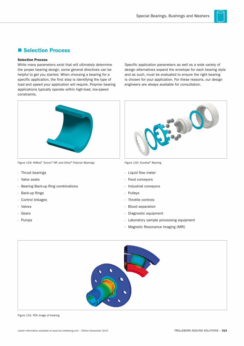
Special Bearings, Bushings and Washers
TRELLEBORG SEALING SOLUTIONS • 313Latest information available at www.tss.trelleborg.com • Edition December 2015
� Selection Process
Selection ProcessWhile many parameters exist that will ultimately determine the proper bearing design, some general directives can be helpful to get you started. When choosing a bearing for a specific application, the first step is identifying the type of load and speed your application will require. Polymer bearing applications typically operate within high-load, low-speed constraints.
Specific application parameters as well as a wide variety of design alternatives expand the envelope for each bearing style and as such, must be evaluated to ensure the right bearing is chosen for your application. For these reasons, our design engineers are always available for consultation.
Figure 129: HiMod®, Turcon® MF, and Orkot® Polymer Bearings
- Thrust bearings
- Valve seats
- Bearing Back-up Ring combinations
- Back-up Rings
- Control linkages
- Valves
- Gears
- Pumps
Figure 130: Durobal® Bearing
- Liquid flow meter
- Food conveyors
- Industrial conveyors
- Pulleys
- Throttle controls
- Blood separation
- Diagnostic equipment
- Laboratory sample processing equipment
- Magnetic Resonance Imaging (MRI)
Figure 131: FEA image of bearing
FBP_neues_Layout_2015.indb 313 17.10.2016 13:38:34
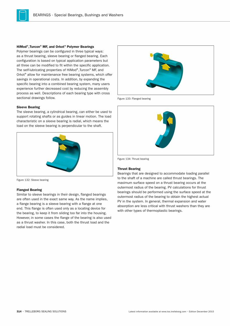
BEARINGS · Special Bearings, Bushings and Washers
314 • TRELLEBORG SEALING SOLUTIONS Latest information available at www.tss.trelleborg.com • Edition December 2015
HiMod®, Turcon® MF, and Orkot® Polymer BearingsPolymer bearings can be configured in three typical ways: as a thrust bearing, sleeve bearing or flanged bearing. Each configuration is based on typical application parameters but all three can be modified to fit within the specific application. The self-lubricating properties of HiMod®, Turcon® MF, and Orkot® allow for maintenance free bearing systems, which offer savings in operational costs. In addition, by expanding the specific bearing into a combined bearing system, many users experience further decreased cost by reducing the assembly process as well. Descriptions of each bearing type with cross sectional drawings follow.
Sleeve Bearing The sleeve bearing, a cylindrical bearing, can either be used to support rotating shafts or as guides in linear motion. The load characteristic on a sleeve bearing is radial, which means the load on the sleeve bearing is perpendicular to the shaft.
Figure 132: Sleeve bearing
Flanged Bearing Similar to sleeve bearings in their design, flanged bearings are often used in the exact same way. As the name implies, a flange bearing is a sleeve bearing with a flange at one end. This flange is often used only as a locating device for the bearing, to keep it from sliding too far into the housing. However, in some cases the flange of the bearing is also used as a thrust washer. In this case, both the thrust load and the radial load must be considered.
Figure 133: Flanged bearing
Figure 134: Thrust bearing
Thrust BearingBearings that are designed to accommodate loading parallel to the shaft of a machine are called thrust bearings. The maximum surface speed on a thrust bearing occurs at the outermost radius of the bearing. PV calculations for thrust bearings should be performed using the surface speed at the outermost radius of the bearing to obtain the highest actual PV in the system. In general, thermal expansion and water absorption are less critical with thrust washers than they are with other types of thermoplastic bearings.
FBP_neues_Layout_2015.indb 314 17.10.2016 13:38:35
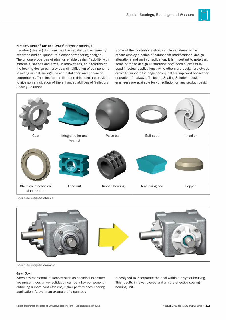
Special Bearings, Bushings and Washers
TRELLEBORG SEALING SOLUTIONS • 315Latest information available at www.tss.trelleborg.com • Edition December 2015
HiMod®, Turcon® MF and Orkot® Polymer BearingsTrelleborg Sealing Solutions has the capabilities, engineering expertise and equipment to pioneer new bearing designs. The unique properties of plastics enable design flexibility with materials, shapes and sizes. In many cases, an alteration of the bearing design can provide a simplification of components resulting in cost savings, easier installation and enhanced performance. The illustrations listed on this page are provided to give some indication of the enhanced abilities of Trelleborg Sealing Solutions.
Some of the illustrations show simple variations, while others employ a series of component modifications, design alterations and part consolidation. It is important to note that some of these design illustrations have been successfully used in actual applications, while others are design prototypes drawn to support the engineer’s quest for improved application operation. As always, Trelleborg Sealing Solutions design engineers are available for consultation on any product design.
Gear Integral roller and bearing
Valve ball Ball seat Impeller
Chemical mechanical planerization
Lead nut Ribbed bearing Tensioning pad Poppet
Figure 135: Design Capabilities
Figure 136: Design Consolidation
Gear Box When environmental influences such as chemical exposure are present, design consolidation can be a key component in obtaining a more cost efficient, higher performance bearing application. Above is an example of a gear box
redesigned to incorporate the seal within a polymer housing. This results in fewer pieces and a more effective sealing/bearing unit.
FBP_neues_Layout_2015.indb 315 17.10.2016 13:38:36

BEARINGS · Special Bearings, Bushings and Washers
316 • TRELLEBORG SEALING SOLUTIONS Latest information available at www.tss.trelleborg.com • Edition December 2015
FBP_neues_Layout_2015.indb 316 17.10.2016 13:38:37
Special SolutionS
TRELLEBORG SEALING SOLUTIONS • 317Latest information available at www.tss.trelleborg.com • Edition December 2015
SpecialSolutionsSpecialSolutionsSpecial
FBP_neues_Layout_2015.indb 317 17.10.2016 13:38:41

318 • TRELLEBORG SEALING SOLUTIONS Latest information available at www.tss.trelleborg.com • Edition December 2015
SPECIAL SOLUTIONS
FBP_neues_Layout_2015.indb 318 17.10.2016 13:38:41
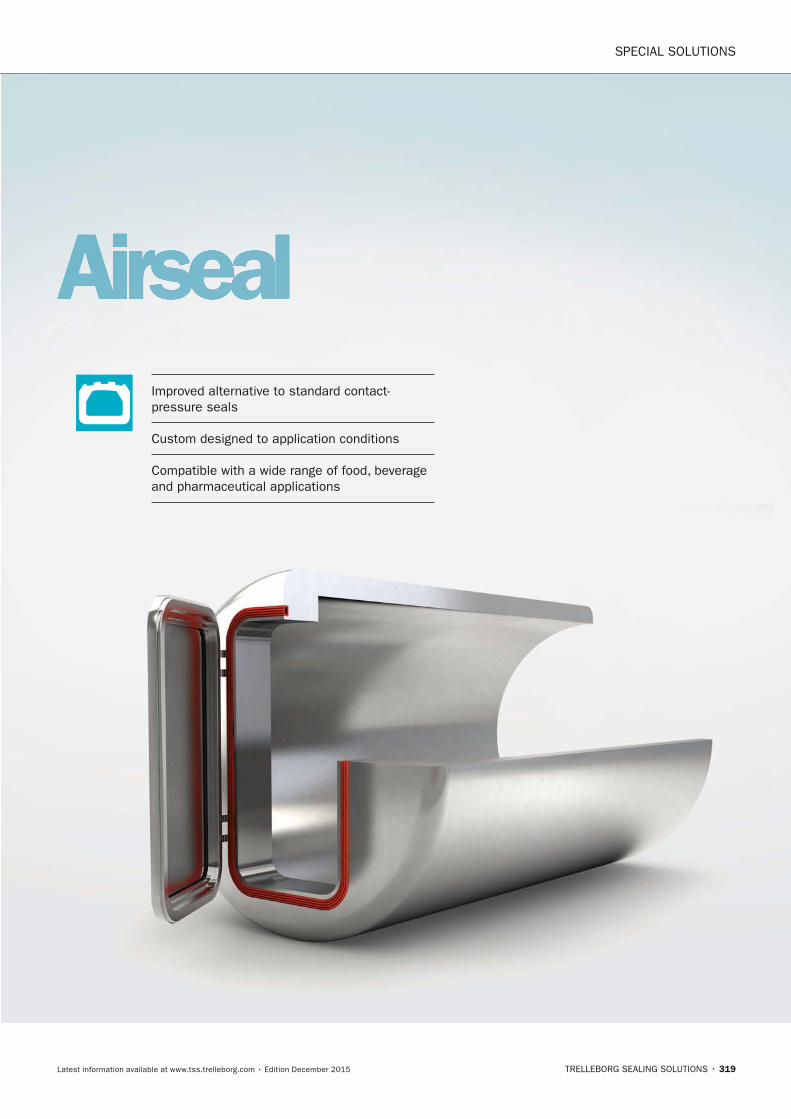
SPECIAL SOLUTIONS
TRELLEBORG SEALING SOLUTIONS • 319Latest information available at www.tss.trelleborg.com • Edition December 2015
AirsealImproved alternative to standard contact- pressure seals
Custom designed to application conditions
Compatible with a wide range of food, beverage and pharmaceutical applications
FBP_neues_Layout_2015.indb 319 17.10.2016 13:38:43

SPECIAL SOLUTIONS · Airseal
320 • TRELLEBORG SEALING SOLUTIONS Latest information available at www.tss.trelleborg.com • Edition December 2015
FBP_neues_Layout_2015.indb 320 17.10.2016 13:38:43
Airseal
TRELLEBORG SEALING SOLUTIONS • 321Latest information available at www.tss.trelleborg.com • Edition December 2015
DESCRIPTIOn
Airseals are inflatable, tubular, elastomer seals activated by internal pressurization. They represent a technically improved alternative to the standard contact-pressure seals. Airseals are used in food, beverage and pharmaceutical applications to prevent scattering of food or medicine powder, to make isolation chambers and to prevent exposure to bacteria and smoke.
Airseals are custom-designed and can easily be adapted to match application conditions and hardware. The wide range of high-pressure and low pressure seals and the numerous FDA-compliant elastomer materials help provide a customized seal suited to the application.
ADVAnTAGES
Airseals offer a large number of advantages compared with conventional contact pressure seals:
- Faster and tighter closing of large sealing surfaces, able to seal gaps with wide tolerances
- No deterioration in the sealing function over the service life
- Tight sealing at pressure and under vacuum conditions
- Automatic pressure monitoring possible
- No high demands on the flatness and surface finish of the mating surface
- High mechanical load-bearing strength owing to fabric reinforcement
- Long service life even with frequent load changes
To design an Airseal, choose four elements suited to your hardware and operating conditions:
- Cross section
- Material
- Direction of inflation
- Corner figure
AVAILABLE MATERIALS
VMQ, EPDM, NBR, CR, FKM, NR, IIR, and FVMQ
- EPDM is typically recommended for food, beverage and pharmaceutical.
- EPDM and VMQ materials are available with FDA compliance.
FBP_neues_Layout_2015.indb 321 17.10.2016 13:38:43
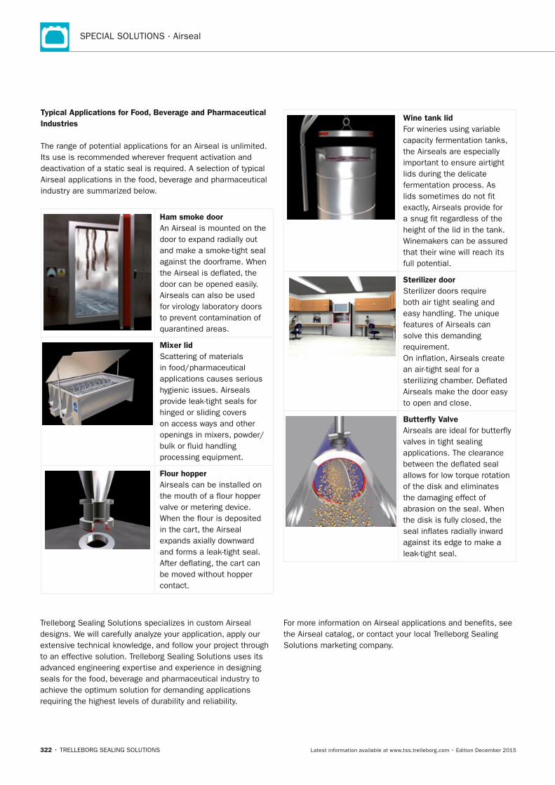
SPECIAL SOLUTIONS · Airseal
322 • TRELLEBORG SEALING SOLUTIONS Latest information available at www.tss.trelleborg.com • Edition December 2015
Typical Applications for Food, Beverage and Pharmaceutical Industries
The range of potential applications for an Airseal is unlimited. Its use is recommended wherever frequent activation and deactivation of a static seal is required. A selection of typical Airseal applications in the food, beverage and pharmaceutical industry are summarized below.
Ham smoke doorAn Airseal is mounted on the door to expand radially out and make a smoke-tight seal against the doorframe. When the Airseal is deflated, the door can be opened easily. Airseals can also be used for virology laboratory doors to prevent contamination of quarantined areas.
Mixer lidScattering of materials in food/pharmaceutical applications causes serious hygienic issues. Airseals provide leak-tight seals for hinged or sliding covers on access ways and other openings in mixers, powder/bulk or fluid handling processing equipment.
Flour hopperAirseals can be installed on the mouth of a flour hopper valve or metering device. When the flour is deposited in the cart, the Airseal expands axially downward and forms a leak-tight seal. After deflating, the cart can be moved without hopper contact.
Wine tank lidFor wineries using variable capacity fermentation tanks, the Airseals are especially important to ensure airtight lids during the delicate fermentation process. As lids sometimes do not fit exactly, Airseals provide for a snug fit regardless of the height of the lid in the tank. Winemakers can be assured that their wine will reach its full potential.
Sterilizer doorSterilizer doors require both air tight sealing and easy handling. The unique features of Airseals can solve this demanding requirement.On inflation, Airseals create an air-tight seal for a sterilizing chamber. Deflated Airseals make the door easy to open and close.
Butterfly ValveAirseals are ideal for butterfly valves in tight sealing applications. The clearance between the deflated seal allows for low torque rotation of the disk and eliminates the damaging effect of abrasion on the seal. When the disk is fully closed, the seal inflates radially inward against its edge to make a leak-tight seal.
Trelleborg Sealing Solutions specializes in custom Airseal designs. We will carefully analyze your application, apply our extensive technical knowledge, and follow your project through to an effective solution. Trelleborg Sealing Solutions uses its advanced engineering expertise and experience in designing seals for the food, beverage and pharmaceutical industry to achieve the optimum solution for demanding applications requiring the highest levels of durability and reliability.
For more information on Airseal applications and benefits, see the Airseal catalog, or contact your local Trelleborg Sealing Solutions marketing company.
FBP_neues_Layout_2015.indb 322 17.10.2016 13:38:45
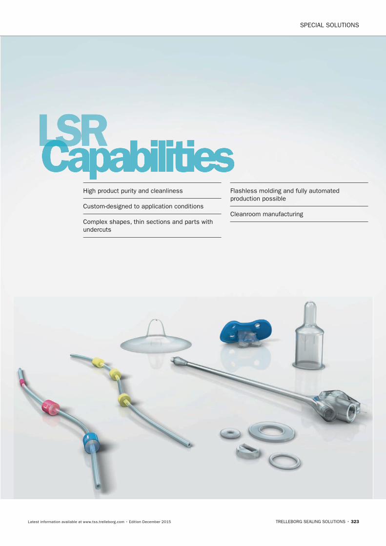
SPECIAL SOLUTIONS
TRELLEBORG SEALING SOLUTIONS • 323Latest information available at www.tss.trelleborg.com • Edition December 2015
LSRCapabilitiesLSRCapabilitiesLSRHigh product purity and cleanliness
Custom-designed to application conditions
Complex shapes, thin sections and parts with undercuts
Flashless molding and fully automated production possible
Cleanroom manufacturing
FBP_neues_Layout_2015.indb 323 17.10.2016 13:38:50

324 • TRELLEBORG SEALING SOLUTIONS Latest information available at www.tss.trelleborg.com • Edition December 2015
SPECIAL SOLUTIONS · LSR Capabilities
FBP_neues_Layout_2015.indb 324 17.10.2016 13:38:50
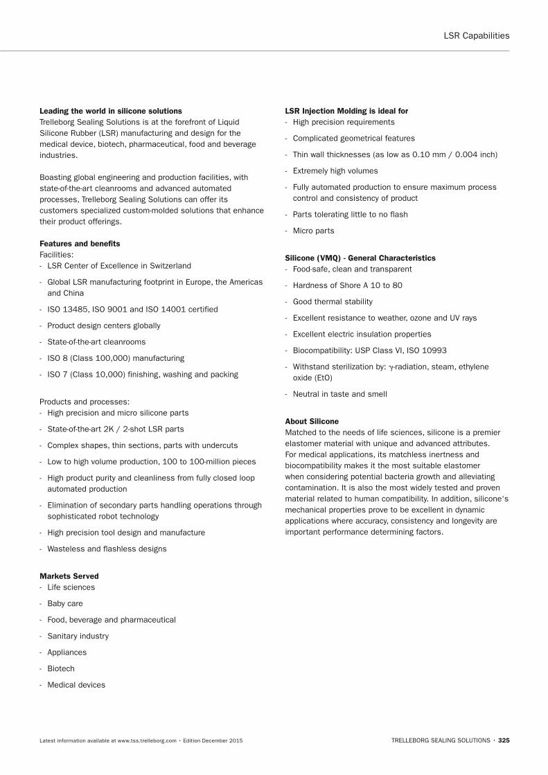
TRELLEBORG SEALING SOLUTIONS • 325Latest information available at www.tss.trelleborg.com • Edition December 2015
LSR Capabilities
Leading the world in silicone solutionsTrelleborg Sealing Solutions is at the forefront of Liquid Silicone Rubber (LSR) manufacturing and design for the medical device, biotech, pharmaceutical, food and beverage industries.
Boasting global engineering and production facilities, with state-of-the-art cleanrooms and advanced automated processes, Trelleborg Sealing Solutions can offer its customers specialized custom-molded solutions that enhance their product offerings.
Features and benefitsFacilities: - LSR Center of Excellence in Switzerland
- Global LSR manufacturing footprint in Europe, the Americas and China
- ISO 13485, ISO 9001 and ISO 14001 certified
- Product design centers globally
- State-of-the-art cleanrooms
- ISO 8 (Class 100,000) manufacturing
- ISO 7 (Class 10,000) finishing, washing and packing
Products and processes: - High precision and micro silicone parts
- State-of-the-art 2K / 2-shot LSR parts
- Complex shapes, thin sections, parts with undercuts
- Low to high volume production, 100 to 100-million pieces
- High product purity and cleanliness from fully closed loop automated production
- Elimination of secondary parts handling operations through sophisticated robot technology
- High precision tool design and manufacture
- Wasteless and flashless designs
Markets Served - Life sciences
- Baby care
- Food, beverage and pharmaceutical
- Sanitary industry
- Appliances
- Biotech
- Medical devices
LSR Injection Molding is ideal for - High precision requirements
- Complicated geometrical features
- Thin wall thicknesses (as low as 0.10 mm / 0.004 inch)
- Extremely high volumes
- Fully automated production to ensure maximum process control and consistency of product
- Parts tolerating little to no flash
- Micro parts
Silicone (VMQ) - General Characteristics - Food-safe, clean and transparent
- Hardness of Shore A 10 to 80
- Good thermal stability
- Excellent resistance to weather, ozone and UV rays
- Excellent electric insulation properties
- Biocompatibility: USP Class VI, ISO 10993
- Withstand sterilization by: -radiation, steam, ethylene oxide (EtO)
- Neutral in taste and smell
About SiliconeMatched to the needs of life sciences, silicone is a premier elastomer material with unique and advanced attributes.For medical applications, its matchless inertness and biocompatibility makes it the most suitable elastomer when considering potential bacteria growth and alleviating contamination. It is also the most widely tested and proven material related to human compatibility. In addition, silicone‘s mechanical properties prove to be excellent in dynamic applications where accuracy, consistency and longevity are important performance determining factors.
FBP_neues_Layout_2015.indb 325 17.10.2016 13:38:50

326 • TRELLEBORG SEALING SOLUTIONS Latest information available at www.tss.trelleborg.com • Edition December 2015
SPECIAL SOLUTIONS · LSR Capabilities
FBP_neues_Layout_2015.indb 326 17.10.2016 13:38:50
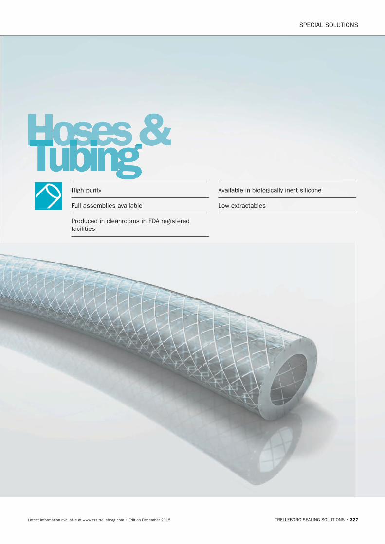
SPECIAL SOLUTIONS
TRELLEBORG SEALING SOLUTIONS • 327Latest information available at www.tss.trelleborg.com • Edition December 2015
Hoses &TubingHoses &TubingHoses &High purity
Full assemblies available
Produced in cleanrooms in FDA registered facilities
Available in biologically inert silicone
Low extractables
FBP_neues_Layout_2015.indb 327 17.10.2016 13:38:56

SPECIAL SOLUTIONS · Hoses & Tubing
328 • TRELLEBORG SEALING SOLUTIONS Latest information available at www.tss.trelleborg.com • Edition December 2015
FBP_neues_Layout_2015.indb 328 17.10.2016 13:38:56
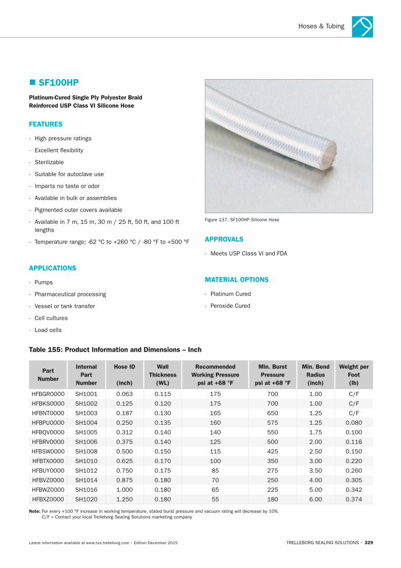
Hoses & Tubing
TRELLEBORG SEALING SOLUTIONS • 329Latest information available at www.tss.trelleborg.com • Edition December 2015
� SF100HPPlatinum-Cured Single Ply Polyester Braid Reinforced USP Class VI Silicone Hose
FEATURES
- High pressure ratings
- Excellent flexibility
- Sterilizable
- Suitable for autoclave use
- Imparts no taste or odor
- Available in bulk or assemblies
- Pigmented outer covers available
- Available in 7 m, 15 m, 30 m / 25 ft, 50 ft, and 100 ft lengths
- Temperature range: -62 °C to +260 °C / -80 °F to +500 °F
APPLICATIOnS
- Pumps
- Pharmaceutical processing
- Vessel or tank transfer
- Cell cultures
- Load cells
Figure 137: SF100HP Silicone Hose
APPROVALS
- Meets USP Class VI and FDA
MATERIAL OPTIOnS
- Platinum Cured
- Peroxide Cured
Table 155: Product Information and Dimensions – Inch
Part number
Internal Part
number
Hose ID
(inch)
Wall Thickness
(WL)
Recommended Working Pressure
psi at +68 °F
Min. Burst Pressure
psi at +68 °F
Min. Bend Radius(inch)
Weight per Foot(lb)
HFBGR0000 SH1001 0.063 0.115 175 700 1.00 C/F
HFBKS0000 SH1002 0.125 0.120 175 700 1.00 C/F
HFBNT0000 SH1003 0.187 0.130 165 650 1.25 C/F
HFBPU0000 SH1004 0.250 0.135 160 575 1.25 0.080
HFBQV0000 SH1005 0.312 0.140 140 550 1.75 0.100
HFBRV0000 SH1006 0.375 0.140 125 500 2.00 0.116
HFBSW0000 SH1008 0.500 0.150 115 425 2.50 0.150
HFBTX0000 SH1010 0.625 0.170 100 350 3.00 0.220
HFBUY0000 SH1012 0.750 0.175 85 275 3.50 0.260
HFBVZ0000 SH1014 0.875 0.180 70 250 4.00 0.305
HFBWZ0000 SH1016 1.000 0.180 65 225 5.00 0.342
HFBXZ0000 SH1020 1.250 0.180 55 180 6.00 0.374
note: For every +100 °F increase in working temperature, stated burst pressure and vacuum rating will decrease by 10%. C/F = Contact your local Trelleborg Sealing Solutions marketing company
FBP_neues_Layout_2015.indb 329 17.10.2016 13:38:57
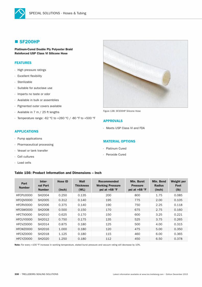
SPECIAL SOLUTIONS · Hoses & Tubing
330 • TRELLEBORG SEALING SOLUTIONS Latest information available at www.tss.trelleborg.com • Edition December 2015
� SF200HPPlatinum-Cured Double Ply Polyester Braid Reinforced USP Class VI Silicone Hose
FEATURES
- High pressure ratings
- Excellent flexibility
- Sterilizable
- Suitable for autoclave use
- Imparts no taste or odor
- Available in bulk or assemblies
- Pigmented outer covers available
- Available in 7 m / 25 ft lengths
- Temperature range: -62 °C to +260 °C / -80 °F to +500 °F
APPLICATIOnS
- Pump applications
- Pharmaceutical processing
- Vessel or tank transfer
- Cell cultures
- Load cells
Figure 138: SF200HP Silicone Hose
APPROVALS
- Meets USP Class VI and FDA
MATERIAL OPTIOnS
- Platinum Cured
- Peroxide Cured
Table 156: Product Information and Dimensions – Inch
Part number
Inter-nal Part number
Hose ID
(inch)
Wall Thickness
(WL)
Recommended Working Pressure
psi at +68 °F
Min. Burst Pressure
psi at +68 °F
Min. Bend Radius(inch)
Weight per Foot(lb)
HFCPU0000 SH2004 0.250 0.135 200 800 1.75 0.085
HFCQV0000 SH2005 0.312 0.140 195 775 2.00 0.105
HFCRV0000 SH2006 0.375 0.140 190 750 2.25 0.118
HFCSW0000 SH2008 0.500 0.150 170 675 2.75 0.160
HFCTX0000 SH2010 0.625 0.170 150 600 3.25 0.221
HFCUY0000 SH2012 0.750 0.175 135 525 3.75 0.265
HFCVZ0000 SH2014 0.875 0.180 125 500 4.00 0.315
HFCWZ0000 SH2016 1.000 0.180 120 475 5.00 0.350
HFCXZ0000 SH2018 1.125 0.180 115 460 6.00 0.365
HFCYZ0000 SH2020 1.250 0.180 112 450 6.50 0.378
note: For every +100 °F increase in working temperature, stated burst pressure and vacuum rating will decrease by 10%.
FBP_neues_Layout_2015.indb 330 17.10.2016 13:38:57
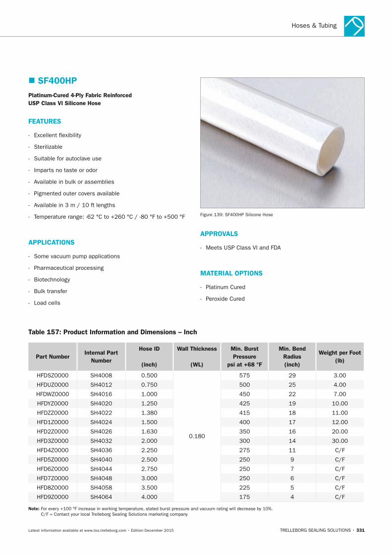
Hoses & Tubing
TRELLEBORG SEALING SOLUTIONS • 331Latest information available at www.tss.trelleborg.com • Edition December 2015
� SF400HPPlatinum-Cured 4-Ply Fabric Reinforced USP Class VI Silicone Hose
FEATURES
- Excellent flexibility
- Sterilizable
- Suitable for autoclave use
- Imparts no taste or odor
- Available in bulk or assemblies
- Pigmented outer covers available
- Available in 3 m / 10 ft lengths
- Temperature range: -62 °C to +260 °C / -80 °F to +500 °F
APPLICATIOnS
- Some vacuum pump applications
- Pharmaceutical processing
- Biotechnology
- Bulk transfer
- Load cells
Figure 139: SF400HP Silicone Hose
APPROVALS
- Meets USP Class VI and FDA
MATERIAL OPTIOnS
- Platinum Cured
- Peroxide Cured
Table 157: Product Information and Dimensions – Inch
Part numberInternal Part
number
Hose ID
(inch)
Wall Thickness
(WL)
Min. Burst Pressure
psi at +68 °F
Min. Bend Radius(inch)
Weight per Foot(lb)
HFDSZ0000 SH4008 0.500
0.180
575 29 3.00
HFDUZ0000 SH4012 0.750 500 25 4.00
HFDWZ0000 SH4016 1.000 450 22 7.00
HFDYZ0000 SH4020 1.250 425 19 10.00
HFDZZ0000 SH4022 1.380 415 18 11.00
HFD1Z0000 SH4024 1.500 400 17 12.00
HFD2Z0000 SH4026 1.630 350 16 20.00
HFD3Z0000 SH4032 2.000 300 14 30.00
HFD4Z0000 SH4036 2.250 275 11 C/F
HFD5Z0000 SH4040 2.500 250 9 C/F
HFD6Z0000 SH4044 2.750 250 7 C/F
HFD7Z0000 SH4048 3.000 250 6 C/F
HFD8Z0000 SH4058 3.500 225 5 C/F
HFD9Z0000 SH4064 4.000 175 4 C/F
note: For every +100 °F increase in working temperature, stated burst pressure and vacuum rating will decrease by 10%. C/F = Contact your local Trelleborg Sealing Solutions marketing company
FBP_neues_Layout_2015.indb 331 17.10.2016 13:38:57
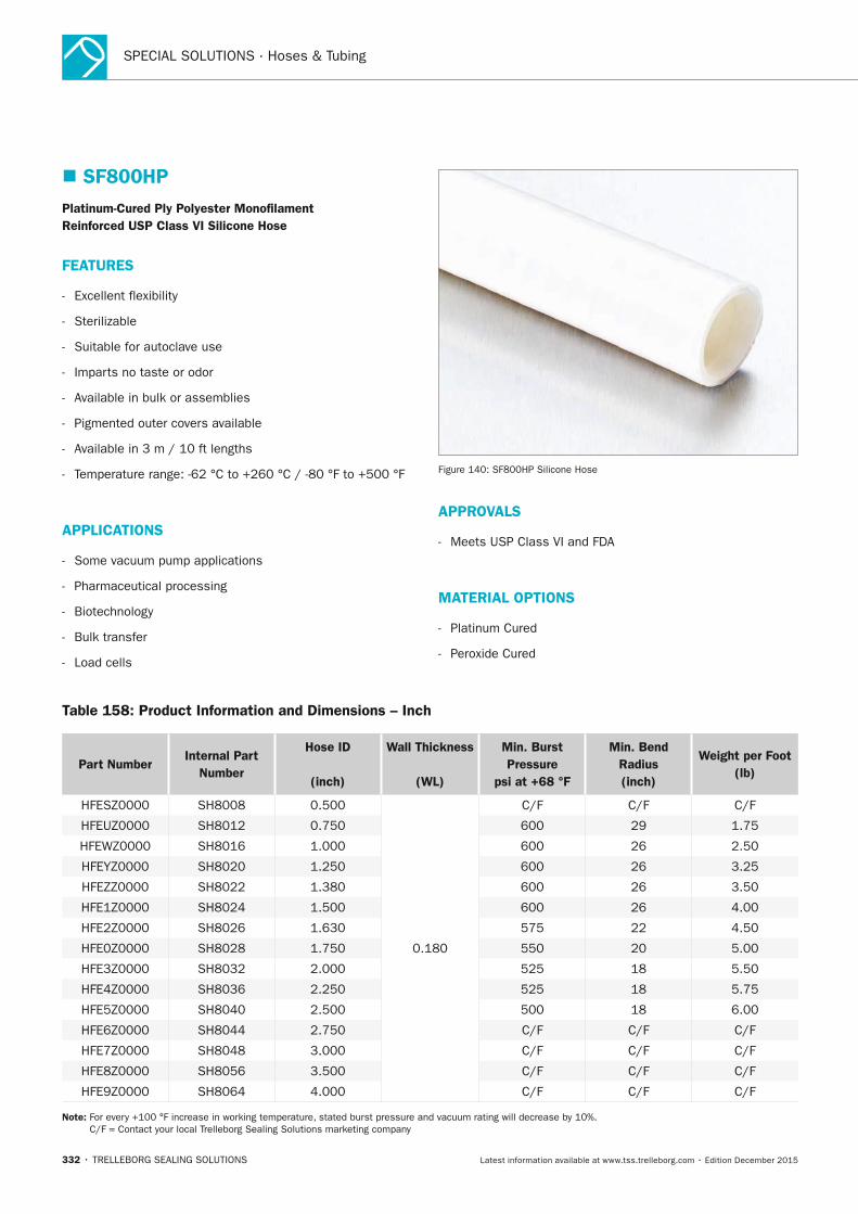
SPECIAL SOLUTIONS · Hoses & Tubing
332 • TRELLEBORG SEALING SOLUTIONS Latest information available at www.tss.trelleborg.com • Edition December 2015
� SF800HPPlatinum-Cured Ply Polyester Monofilament Reinforced USP Class VI Silicone Hose
FEATURES
- Excellent flexibility
- Sterilizable
- Suitable for autoclave use
- Imparts no taste or odor
- Available in bulk or assemblies
- Pigmented outer covers available
- Available in 3 m / 10 ft lengths
- Temperature range: -62 °C to +260 °C / -80 °F to +500 °F
APPLICATIOnS
- Some vacuum pump applications
- Pharmaceutical processing
- Biotechnology
- Bulk transfer
- Load cells
Figure 140: SF800HP Silicone Hose
APPROVALS
- Meets USP Class VI and FDA
MATERIAL OPTIOnS
- Platinum Cured
- Peroxide Cured
Table 158: Product Information and Dimensions – Inch
Part numberInternal Part
number
Hose ID
(inch)
Wall Thickness
(WL)
Min. Burst Pressure
psi at +68 °F
Min. Bend Radius(inch)
Weight per Foot(lb)
HFESZ0000 SH8008 0.500
0.180
C/F C/F C/F
HFEUZ0000 SH8012 0.750 600 29 1.75
HFEWZ0000 SH8016 1.000 600 26 2.50
HFEYZ0000 SH8020 1.250 600 26 3.25
HFEZZ0000 SH8022 1.380 600 26 3.50
HFE1Z0000 SH8024 1.500 600 26 4.00
HFE2Z0000 SH8026 1.630 575 22 4.50
HFE0Z0000 SH8028 1.750 550 20 5.00
HFE3Z0000 SH8032 2.000 525 18 5.50
HFE4Z0000 SH8036 2.250 525 18 5.75
HFE5Z0000 SH8040 2.500 500 18 6.00
HFE6Z0000 SH8044 2.750 C/F C/F C/F
HFE7Z0000 SH8048 3.000 C/F C/F C/F
HFE8Z0000 SH8056 3.500 C/F C/F C/F
HFE9Z0000 SH8064 4.000 C/F C/F C/F
note: For every +100 °F increase in working temperature, stated burst pressure and vacuum rating will decrease by 10%. C/F = Contact your local Trelleborg Sealing Solutions marketing company
FBP_neues_Layout_2015.indb 332 17.10.2016 13:38:58
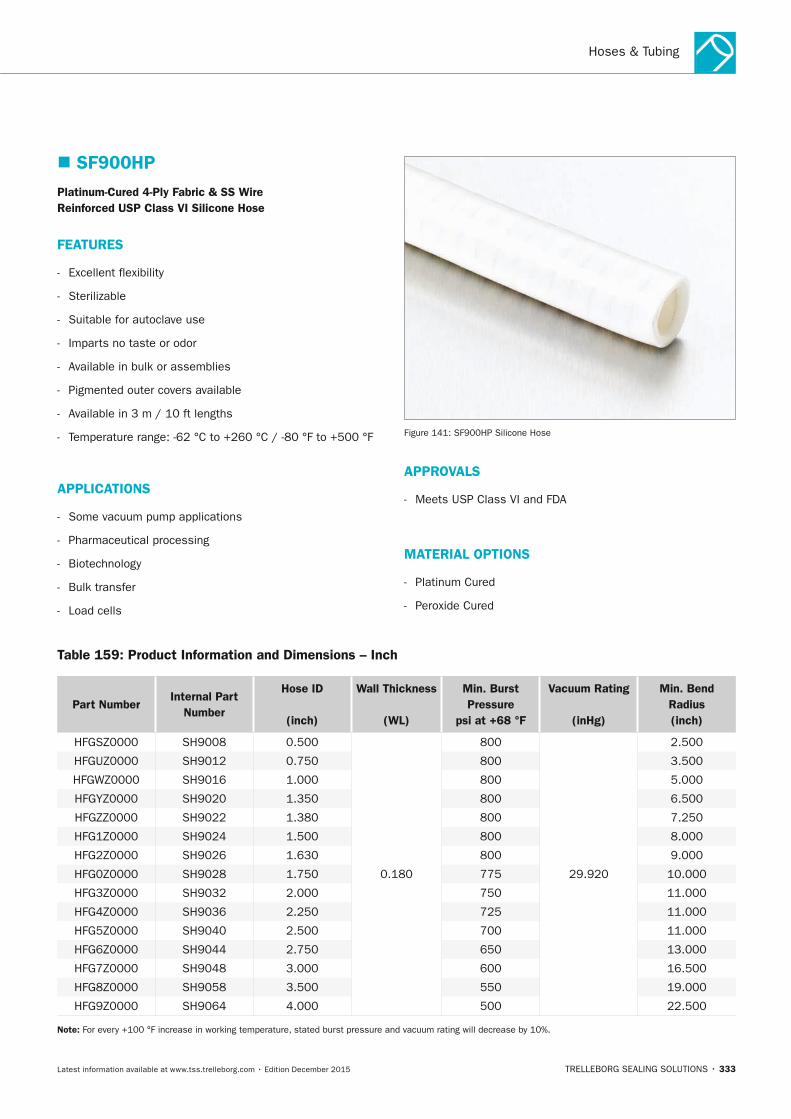
Hoses & Tubing
TRELLEBORG SEALING SOLUTIONS • 333Latest information available at www.tss.trelleborg.com • Edition December 2015
� SF900HPPlatinum-Cured 4-Ply Fabric & SS Wire Reinforced USP Class VI Silicone Hose
FEATURES
- Excellent flexibility
- Sterilizable
- Suitable for autoclave use
- Imparts no taste or odor
- Available in bulk or assemblies
- Pigmented outer covers available
- Available in 3 m / 10 ft lengths
- Temperature range: -62 °C to +260 °C / -80 °F to +500 °F
APPLICATIOnS
- Some vacuum pump applications
- Pharmaceutical processing
- Biotechnology
- Bulk transfer
- Load cells
Figure 141: SF900HP Silicone Hose
APPROVALS
- Meets USP Class VI and FDA
MATERIAL OPTIOnS
- Platinum Cured
- Peroxide Cured
Table 159: Product Information and Dimensions – Inch
Part numberInternal Part
number
Hose ID
(inch)
Wall Thickness
(WL)
Min. Burst Pressure
psi at +68 °F
Vacuum Rating
(inHg)
Min. Bend Radius(inch)
HFGSZ0000 SH9008 0.500
0.180
800
29.920
2.500
HFGUZ0000 SH9012 0.750 800 3.500
HFGWZ0000 SH9016 1.000 800 5.000
HFGYZ0000 SH9020 1.350 800 6.500
HFGZZ0000 SH9022 1.380 800 7.250
HFG1Z0000 SH9024 1.500 800 8.000
HFG2Z0000 SH9026 1.630 800 9.000
HFG0Z0000 SH9028 1.750 775 10.000
HFG3Z0000 SH9032 2.000 750 11.000
HFG4Z0000 SH9036 2.250 725 11.000
HFG5Z0000 SH9040 2.500 700 11.000
HFG6Z0000 SH9044 2.750 650 13.000
HFG7Z0000 SH9048 3.000 600 16.500
HFG8Z0000 SH9058 3.500 550 19.000
HFG9Z0000 SH9064 4.000 500 22.500
note: For every +100 °F increase in working temperature, stated burst pressure and vacuum rating will decrease by 10%.
FBP_neues_Layout_2015.indb 333 17.10.2016 13:38:58
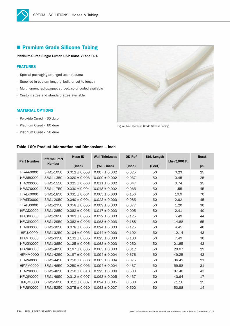
SPECIAL SOLUTIONS · Hoses & Tubing
334 • TRELLEBORG SEALING SOLUTIONS Latest information available at www.tss.trelleborg.com • Edition December 2015
� Premium Grade Silicone TubingPlatinum-Cured Single Lumen USP Class VI and FDA
FEATURES
- Special packaging arranged upon request
- Supplied in custom lengths, bulk, or cut to length
- Multi lumen, radiopaque, striped, color coded available
- Custom sizes and standard sizes available
MATERIAL OPTIOnS
- Peroxide Cured - 60 duro
- Platinum Cured - 60 duro
- Platinum Cured - 50 duro
Figure 142: Premium Grade Silicone Tubing
Table 160: Product Information and Dimensions – Inch
Part numberInternal Part
number
Hose ID
(inch)
Wall Thickness
(WL - inch)
OD Ref
(inch)
Std. Length
(Feet)Lbs/1000 ft.
Burst
psi
HFAAA0000 SFM1-1050 0.012 ± 0.003 0.007 ± 0.002 0.025 50 0.23 25
HFABB0000 SFM1-1350 0.020 ± 0.003 0.009 ± 0.002 0.037 50 0.45 25
HFACC0000 SFM1-1550 0.025 ± 0.003 0.011 ± 0.002 0.047 50 0.74 35
HFADZ0000 SFM1-1750 0.030 ± 0.004 0.018 ± 0.002 0.065 50 1.55 45
HFALK0000 SFM1-1850 0.031 ± 0.004 0.063 ± 0.003 0.156 50 10.9 70
HFAEE0000 SFM1-2050 0.040 ± 0.004 0.023 ± 0.003 0.085 50 2.62 45
HFAFB0000 SFM1-2350 0.058 ± 0.005 0.009 ± 0.003 0.077 50 1.20 30
HFAGD0000 SFM1-2650 0.062 ± 0.005 0.017 ± 0.003 0.095 50 2.41 40
HFAGG0000 SFM1-2850 0.062 ± 0.005 0.032 ± 0.003 0.125 50 5.49 44
HFAGK0000 SFM1-2950 0.062 ± 0.005 0.063 ± 0.003 0.188 50 14.68 65
HFAHP0000 SFM1-3050 0.078 ± 0.005 0.024 ± 0.003 0.125 50 4.45 40
HFAJJ0000 SFM1-3250 0.104 ± 0.005 0.044 ± 0.003 0.192 50 12.14 43
HFAMF0000 SFM1-3350 0.132 ± 0.005 0.025 ± 0.003 0.183 50 7.49 30
HFAKK0000 SFM1-3650 0.125 ± 0.005 0.063 ± 0.003 0.250 50 21.85 43
HFANK0000 SFM1-4050 0.187 ± 0.005 0.063 ± 0.003 0.312 50 29.07 29
HFANM0000 SFM1-4250 0.187 ± 0.005 0.094 ± 0.004 0.375 50 49.25 43
HFAPK0000 SFM1-4450 0.250 ± 0.006 0.063 ± 0.004 0.375 50 36.42 21
HFAPM0000 SFM1-4650 0.250 ± 0.006 0.094 ± 0.004 0.437 50 59.98 31
HFAPN0000 SFM1-4850 0.250 ± 0.010 0.125 ± 0.008 0.500 50 87.40 43
HFAQK0000 SFM1-4950 0.312 ± 0.007 0.063 ± 0.005 0.437 50 43.64 17
HFAQM0000 SFM1-5050 0.312 ± 0.007 0.094 ± 0.005 0.500 50 71.16 25
HFARK0000 SFM1-5250 0.375 ± 0.010 0.063 ± 0.007 0.500 50 50.98 14
FBP_neues_Layout_2015.indb 334 17.10.2016 13:38:58
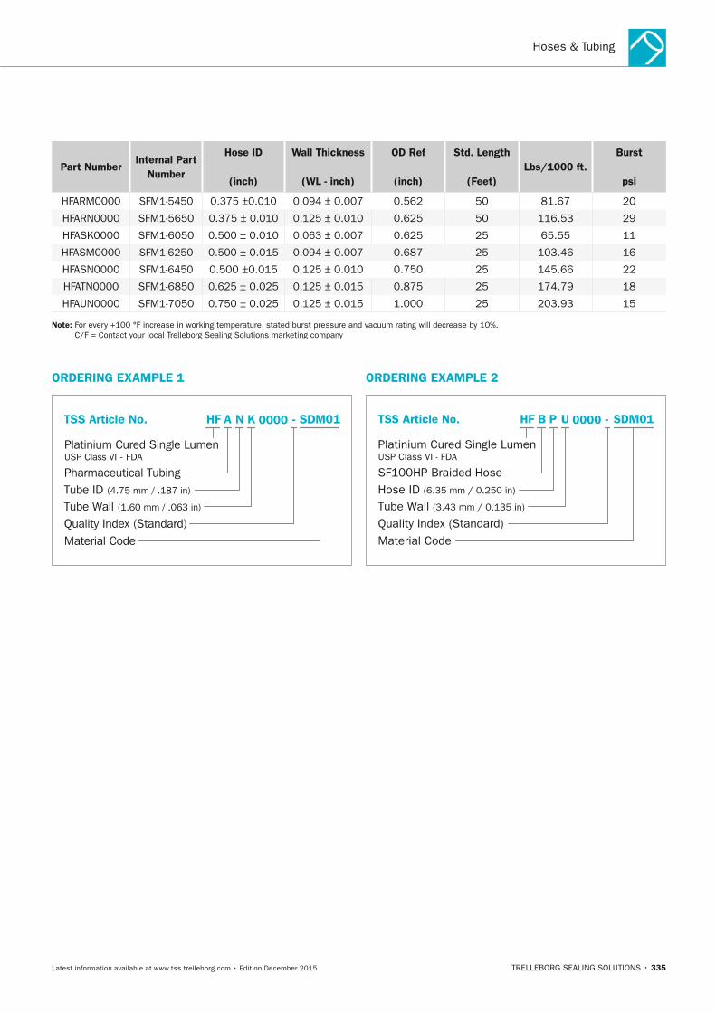
Hoses & Tubing
TRELLEBORG SEALING SOLUTIONS • 335Latest information available at www.tss.trelleborg.com • Edition December 2015
Part numberInternal Part
number
Hose ID
(inch)
Wall Thickness
(WL - inch)
OD Ref
(inch)
Std. Length
(Feet)Lbs/1000 ft.
Burst
psi
HFARM0000 SFM1-5450 0.375 ±0.010 0.094 ± 0.007 0.562 50 81.67 20
HFARN0000 SFM1-5650 0.375 ± 0.010 0.125 ± 0.010 0.625 50 116.53 29
HFASK0000 SFM1-6050 0.500 ± 0.010 0.063 ± 0.007 0.625 25 65.55 11
HFASM0000 SFM1-6250 0.500 ± 0.015 0.094 ± 0.007 0.687 25 103.46 16
HFASN0000 SFM1-6450 0.500 ±0.015 0.125 ± 0.010 0.750 25 145.66 22
HFATN0000 SFM1-6850 0.625 ± 0.025 0.125 ± 0.015 0.875 25 174.79 18
HFAUN0000 SFM1-7050 0.750 ± 0.025 0.125 ± 0.015 1.000 25 203.93 15
note: For every +100 °F increase in working temperature, stated burst pressure and vacuum rating will decrease by 10%. C/F = Contact your local Trelleborg Sealing Solutions marketing company
ORDERInG ExAMPLE 1
Tube Wall (1.60 mm / .063 in)
Platinium Cured Single LumenUSP Class VI - FDA
TSS Article No.
Quality Index (Standard)Material Code
Pharmaceutical TubingTube ID (4.75 mm / .187 in)
0000N K -HF SDM01A
ORDERInG ExAMPLE 2
Tube Wall (3.43 mm / 0.135 in)
Platinium Cured Single LumenUSP Class VI - FDA
TSS Article No.
Quality Index (Standard)Material Code
SF100HP Braided HoseHose ID (6.35 mm / 0.250 in)
0000P U -HF SDM01B
FBP_neues_Layout_2015.indb 335 17.10.2016 13:38:59

SPECIAL SOLUTIONS · Hoses & Tubing
336 • TRELLEBORG SEALING SOLUTIONS Latest information available at www.tss.trelleborg.com • Edition December 2015
FBP_neues_Layout_2015.indb 336 17.10.2016 13:38:59

Storage advice
TRELLEBORG SEALING SOLUTIONS • 337Latest information available at www.tss.trelleborg.com • Edition December 2015
General Quality CriteriaGeneral Quality Criteriaand Storage Guidelinesand Storage GuidelinesGeneral Quality Criteriaand Storage GuidelinesGeneral Quality Criteria
FBP_neues_Layout_2015.indb 337 17.10.2016 13:39:03

338 • TRELLEBORG SEALING SOLUTIONS Latest information available at www.tss.trelleborg.com • Edition December 2015
STORAGE ADVICE
FBP_neues_Layout_2015.indb 338 17.10.2016 13:39:03
Storage Advice
TRELLEBORG SEALING SOLUTIONS • 339Latest information available at www.tss.trelleborg.com • Edition December 2015
Many polymer products and components are stored for long periods of time before being put into service, so it is important they are stored in conditions that minimize unwanted changes in properties. Changes from degradation may include excessive hardening, softening, cracking, crazing or other surface effects. Other changes may be caused by deformation, contamination or mechanical damage.
PackagingUnless otherwise specified in the appropriate product specification, rubber products should be enclosed in individual sealed envelopes. The packaging should be carried out in an atmosphere in which the relative humidity is less than 70%, or if polyurethanes are being packed, less than 65%. Where there is serious risk of ingress of moisture, for example, for rubber-metal-bonded parts, an aluminium, foil/paper/polyethylene laminate or other similar means of protection should be used to ensure the quality of the seal is preserved.
TemperatureThe storage temperature should be below +25 °C / +77 °F and the products should be stored away from direct sources of heat such as boilers, radiators and direct sunlight. If the storage temperature is below +15 °C / +59 °F, care should be exercised during handling of stored products, as they may have stiffened and have become susceptible to distortion.
HumidityThe relative humidity of a storage environment should be such that condensation does not occur with variations in temperature. In all cases, the relative humidity of the atmosphere in storage should be less than 70%, or if polyurethanes are being stored, less than 65%.
LightRubber should be protected from light sources, in particular direct sunlight or intense light with high ultra-violet content. It is advisable that any storage room windows be covered with a red or orange coating or screen.
RadiationPrecautions should be taken to protect stored products from all sources of ionizing radiation likely to cause damage to the products.
OzoneOzone has a particularly harmful effect on rubber. Storage rooms should not contain any equipment that is capable of generating ozone, such as mercury vapor lamps or high-voltage electrical equipment giving rise to electric sparks or electrical discharges. Combustion gases and organic vapors should also be excluded, as they may give rise to ozone via photo-chemical processes.
When equipment such as a fork-lift truck is used to handle large rubber products, care needs to be taken to ensure this equipment is not a source of pollution that may affect the rubber. Combustion gases should be considered separately. While they are responsible for generating ground-level ozone, they may also contain unburned fuel which, by condensing on rubber products, can cause additional deterioration.
DeformationRubber should be stored free from tension, compressive stresses or other causes of deformation. Where products are packaged in a strain-free condition, they should be stored in their original packaging. In case of doubt, the manufacturer's advice should be sought. It is advisable that rings of large internal diameter are formed into three equal loops so as to avoid creasing or twisting. It is not possible to achieve this condition by forming just two loops.
Contact with liquids and semi-liquid materialsRubber should not be allowed to come into contact with liquid or semi-liquid materials (for example, petrol, greases, acids, disinfectants, cleaning fluids) or their vapors at any time during storage, unless these materials are by design an integral part of the product or the manufacturer's packaging. When rubber products are received coated with their operational media, they should be stored in this condition.
Contact with metalsCertain metals and their alloys, in particular, copper and manganese, are known to have harmful effects on some rubbers. Rubber should not be stored in contact with such metals except when bonded to them. They should be protected by wrapping in, or by separation with, a suitable material, such as paper or polyethylene.
Contact with dusting powderDusting powders should only be used for the packaging of rubber items in order to prevent adhesion. In such cases, the minimum quantity of powder to prevent adhesion should be used. Any powder used should be free from any constituent that would have a harmful effect on the rubber or the subsequent application of the rubber.
Contact between different productsContact between products made from rubbers of different compositions should be avoided. This includes products of the same type but differing in color.
� Guidelines for the Storage of Polymer Products Based on ISO 2230
FBP_neues_Layout_2015.indb 339 17.10.2016 13:39:03
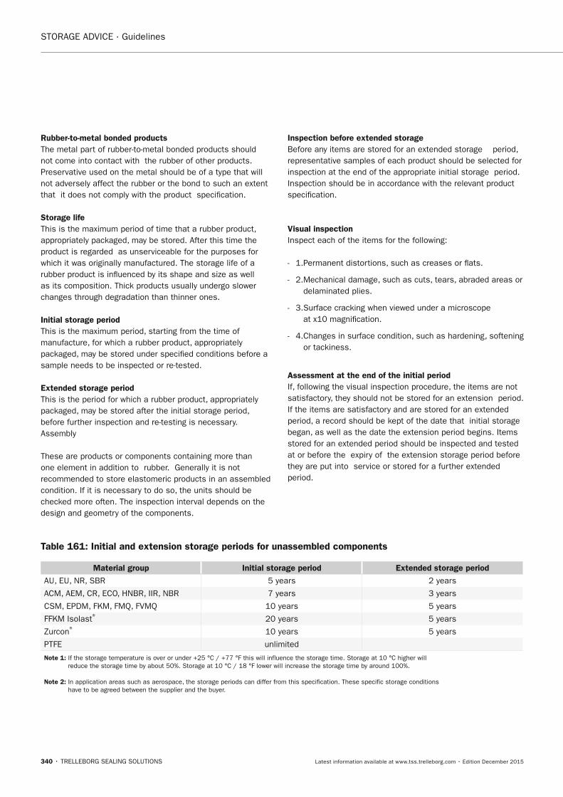
STORAGE ADVICE · Guidelines
340 • TRELLEBORG SEALING SOLUTIONS Latest information available at www.tss.trelleborg.com • Edition December 2015
Table 161: Initial and extension storage periods for unassembled components
Material group Initial storage period Extended storage period
AU, EU, NR, SBR 5 years 2 years
ACM, AEM, CR, ECO, HNBR, IIR, NBR 7 years 3 years
CSM, EPDM, FKM, FMQ, FVMQ 10 years 5 years
FFKM Isolast® 20 years 5 years
Zurcon® 10 years 5 years
PTFE unlimited
note 1: If the storage temperature is over or under +25 °C / +77 °F this will influence the storage time. Storage at 10 °C higher will reduce the storage time by about 50%. Storage at 10 °C / 18 °F lower will increase the storage time by around 100%.
note 2: In application areas such as aerospace, the storage periods can differ from this specification. These specific storage conditions have to be agreed between the supplier and the buyer.
Rubber-to-metal bonded productsThe metal part of rubber-to-metal bonded products should not come into contact with the rubber of other products. Preservative used on the metal should be of a type that will not adversely affect the rubber or the bond to such an extent that it does not comply with the product specification.
Storage lifeThis is the maximum period of time that a rubber product, appropriately packaged, may be stored. After this time the product is regarded as unserviceable for the purposes for which it was originally manufactured. The storage life of a rubber product is influenced by its shape and size as well as its composition. Thick products usually undergo slower changes through degradation than thinner ones.
Initial storage periodThis is the maximum period, starting from the time of manufacture, for which a rubber product, appropriately packaged, may be stored under specified conditions before a sample needs to be inspected or re-tested.
Extended storage periodThis is the period for which a rubber product, appropriately packaged, may be stored after the initial storage period, before further inspection and re-testing is necessary.Assembly
These are products or components containing more than one element in addition to rubber. Generally it is not recommended to store elastomeric products in an assembled condition. If it is necessary to do so, the units should be checked more often. The inspection interval depends on the design and geometry of the components.
Inspection before extended storageBefore any items are stored for an extended storage period, representative samples of each product should be selected for inspection at the end of the appropriate initial storage period. Inspection should be in accordance with the relevant product specification.
Visual inspectionInspect each of the items for the following:
- 1.Permanent distortions, such as creases or flats.
- 2. Mechanical damage, such as cuts, tears, abraded areas or delaminated plies.
- 3. Surface cracking when viewed under a microscope at x10 magnification.
- 4. Changes in surface condition, such as hardening, softening or tackiness.
Assessment at the end of the initial periodIf, following the visual inspection procedure, the items are not satisfactory, they should not be stored for an extension period. If the items are satisfactory and are stored for an extended period, a record should be kept of the date that initial storage began, as well as the date the extension period begins. Items stored for an extended period should be inspected and tested at or before the expiry of the extension storage period before they are put into service or stored for a further extended period.
FBP_neues_Layout_2015.indb 340 17.10.2016 13:39:03
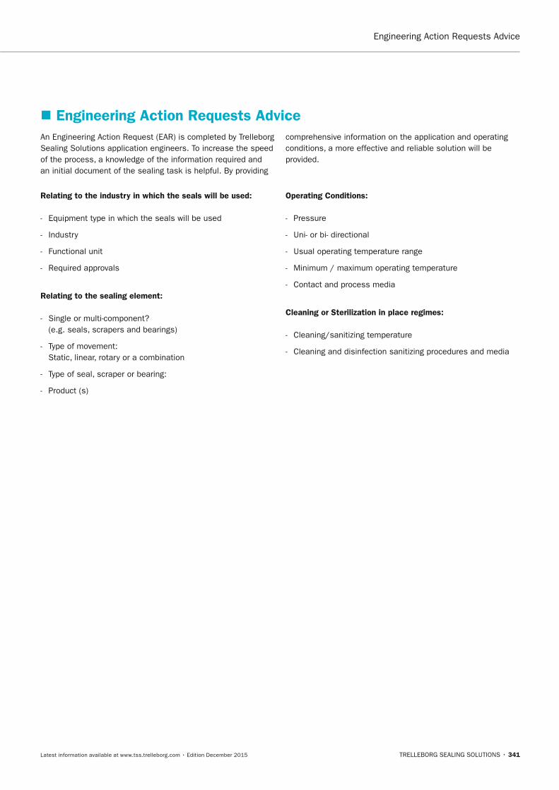
TRELLEBORG SEALING SOLUTIONS • 341Latest information available at www.tss.trelleborg.com • Edition December 2015
Engineering Action Requests Advice
� Engineering Action Requests AdviceAn Engineering Action Request (EAR) is completed by Trelleborg Sealing Solutions application engineers. To increase the speed of the process, a knowledge of the information required and an initial document of the sealing task is helpful. By providing
comprehensive information on the application and operating conditions, a more effective and reliable solution will be provided.
Relating to the industry in which the seals will be used:
- Equipment type in which the seals will be used
- Industry
- Functional unit
- Required approvals
Relating to the sealing element:
- Single or multi-component? (e.g. seals, scrapers and bearings)
- Type of movement: Static, linear, rotary or a combination
- Type of seal, scraper or bearing:
- Product (s)
Operating Conditions:
- Pressure
- Uni- or bi- directional
- Usual operating temperature range
- Minimum / maximum operating temperature
- Contact and process media
Cleaning or Sterilization in place regimes:
- Cleaning/sanitizing temperature
- Cleaning and disinfection sanitizing procedures and media
FBP_neues_Layout_2015.indb 341 17.10.2016 13:39:03

STORAGE ADVICE · Guidelines
342 • TRELLEBORG SEALING SOLUTIONS Latest information available at www.tss.trelleborg.com • Edition December 2015
FBP_neues_Layout_2015.indb 342 17.10.2016 13:39:03

Company overview
TRELLEBORG SEALING SOLUTIONS • 343Latest information available at www.tss.trelleborg.com • Edition December 2015
CompanyOverviewCompanyOverviewCompany
FBP_neues_Layout_2015.indb 343 17.10.2016 13:39:16
OUR MISSIOn We will be the supply partner of first choice within our chosen markets, working globally through our local teams. We will build long-term partnerships with customers and suppliers by providing leading technology and excellent service. We are determined to be different.
SEALInG TECHnOLOGyTrelleborg Sealing Solutions offers an outstandingly comprehensive sealing portfolio – a one-stop-shop providingthe best in elastomer, silicone, thermoplastic, PTFE and composite technologies; our solutions are featured in virtually every application conceivable within the aerospace, industrial and automotive industries.
A WORLDWIDE PRESEnCEWe are uniquely placed to offer a dedicated design and development service for sealing solutions, globally servicing, supporting and supplying our customers through an unrivaledinternational network.
• Over 80 facilities worldwide• More than 20 manufacturing sites• Seven strategically positioned material
and development laboratories• Internationally linked design and
application centers
COMMITMEnT – TO CUSTOMERS’nEEDS LOnG-TERMThe aim of Trelleborg Sealing Solutions is to facilitate customers in achieving cost-effective, durable solutions that match their specific business requirements and needs. We are one of the world's foremost experts in polymer sealing technology. We develop, manufacture and supply safety-critical polymer- based precision seals, bearings and molded components.
Your Partner forSealing TechnologySealing TechnologyYour Partner forSealing TechnologyYour Partner for“We build long term partnerships with customers and suppliers by providing leading technology and excellent service.”
COMPANY OVERVIEW
344 • TRELLEBORG SEALING SOLUTIONS Latest information available at www.tss.trelleborg.com • Edition December 2015
FBP_neues_Layout_2015.indb 344 17.10.2016 13:39:16

THE TRELLEBORG GROUP
Trelleborg Sealing Solutions Key Industries
Automotive Food & Beverage, Chemical Processing
Marine
Machine Tools & Fluid Power
Off-Highway, Agriculture, Construction
Oil & Gas
Aerospace
Life Sciences and Pharmaceutical
Mining Alternative Energy
Trelleborg Coated SystemsLeading global supplier of unique customer solutions for polymer-coated fabrics deployed in a variety of industrial applications.
Trelleborg Offshore & ConstructionLeading global supplier of polymer-based critical solutions for deployment in highly demanding environments.
Trelleborg Wheel SystemsLeading global supplier of tires and complete wheels for agricultural and forestry machines, forklift trucks and other materials handling vehicles.
Trelleborg Industrial SolutionsMarket leader in such industrial application areas as hose systems, industrial antivibration solutions and selected industrial sealing systems.
Trelleborg Sealing SolutionsOne of the world’s leading developers, manufacturers and suppliers of precision seals. It supports its aerospace, industrial and automotive customers through over 20 production facilities and more than 50 marketing companies globally.
COMPANY OVERVIEW
TRELLEBORG SEALING SOLUTIONS • 345Latest information available at www.tss.trelleborg.com • Edition December 2015
FBP_neues_Layout_2015.indb 345 17.10.2016 13:39:28
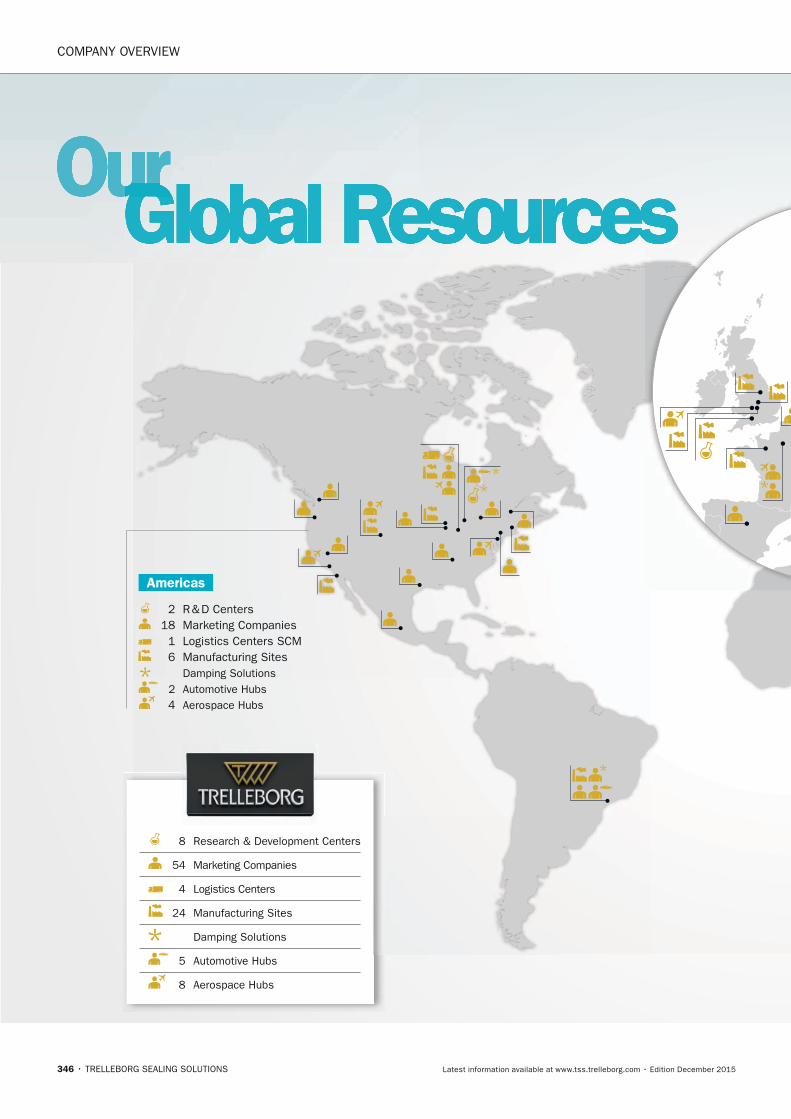
2 R & D Centers 18 Marketing Companies 1 Logistics Centers SCM 6 Manufacturing Sites Damping Solutions 2 Automotive Hubs 4 Aerospace Hubs
8 Research & Development Centers
54 Marketing Companies
4 Logistics Centers
24 Manufacturing Sites
Damping Solutions
5 Automotive Hubs
8 Aerospace Hubs
OurOurOurGlobal ResourcesGlobal ResourcesGlobal ResourcesGlobal ResourcesGlobal ResourcesGlobal ResourcesOurGlobal ResourcesOurOurOurGlobal ResourcesOurGlobal ResourcesOurGlobal ResourcesOurOurOurGlobal ResourcesOur
Americas
COMPANY OVERVIEW
346 • TRELLEBORG SEALING SOLUTIONS Latest information available at www.tss.trelleborg.com • Edition December 2015
FBP_neues_Layout_2015.indb 346 17.10.2016 13:39:30

How local is your global seal supplier?
www.global-but-local.com
1 R & D Centers 15 Marketing Companies 2 Logistics Centers SCM 4 Manufacturing Sites Damping Solutions 2 Automotive Hubs 2 Aerospace Hubs
Europe
5 R & D Centers 21 Marketing Companies 1 Logistics Centers SCM 14 Manufacturing Sites Damping Solutions 1 Automotive Hubs 2 Aerospace Hubs
Asia
82worldwidelocations
5,300employees
More than
2,000proprietary material
formulations
COMPANY OVERVIEW
TRELLEBORG SEALING SOLUTIONS • 347Latest information available at www.tss.trelleborg.com • Edition December 2015
FBP_neues_Layout_2015.indb 347 17.10.2016 13:39:35
•AmericanVariseal•Busak+Shamban•DowtySeals•ChaseWalton•Forsheda•GNL•Impervia•Nordex•Orkot
•PalmerChenard•Polypac•SFMedical•Shamban•Silcofab•Silcotech•Skega•Stefa•Wills
WORLD REnOWnED nAMES UnITEDWe own many of the longest established and leading names within the seal industry. These include:
•Turcon® AQ Seal®
•D-A-SCompactSeal® •Turcon® Double Delta® •Turcon® Excluder® •Turcon® Glyd Ring® T •Turcon® Hatseal•Zurcon® L-Cup® •Turcite® Slydring® •Turcite® B-Slydway®
•Turcon® Stepseal® 2K •V-Ring® •Turcon® Varilip® PDR •Turcon® Variseal® •Turcon® VL-Seal™ •Turcon® Wedgpak® •WillsRings® •Zurcon® Wynseal®
OUR PIOnEERInG PRODUCTSTrelleborg Sealing Solutions is pioneering and is continuously developing innovative products.
•HiMod® •Isolast® •Orkot® •Turcite®
•Turcon®
•Turel® •Zurcon®
PROPRIETARy MATERIALSOngoing development has yielded some of the most successful sealing and bearing materials available.
Products, Brandsand Materialsand MaterialsProducts, Brandsand MaterialsProducts, Brands
To design a solution for your specific needs, contact your local Trelleborg Sealing Solutions marketing company.
Decades of experience designing and manufacturing polymer solutions has led Trelleborg Sealing Solutions to develop, manufacture and supply a range of unique materials and proprietary product designs, many of which have become industry standards. Development is ongoing, ensuring that our solutions meet the changing needs of our customers, as well as the latest industry trends and regulations.
COMPANY OVERVIEW
348 • TRELLEBORG SEALING SOLUTIONS Latest information available at www.tss.trelleborg.com • Edition December 2015
FBP_neues_Layout_2015.indb 348 17.10.2016 13:39:37

COMPANY OVERVIEW
TRELLEBORG SEALING SOLUTIONS • 349Latest information available at www.tss.trelleborg.com • Edition December 2015
FBP_neues_Layout_2015.indb 349 17.10.2016 13:39:39
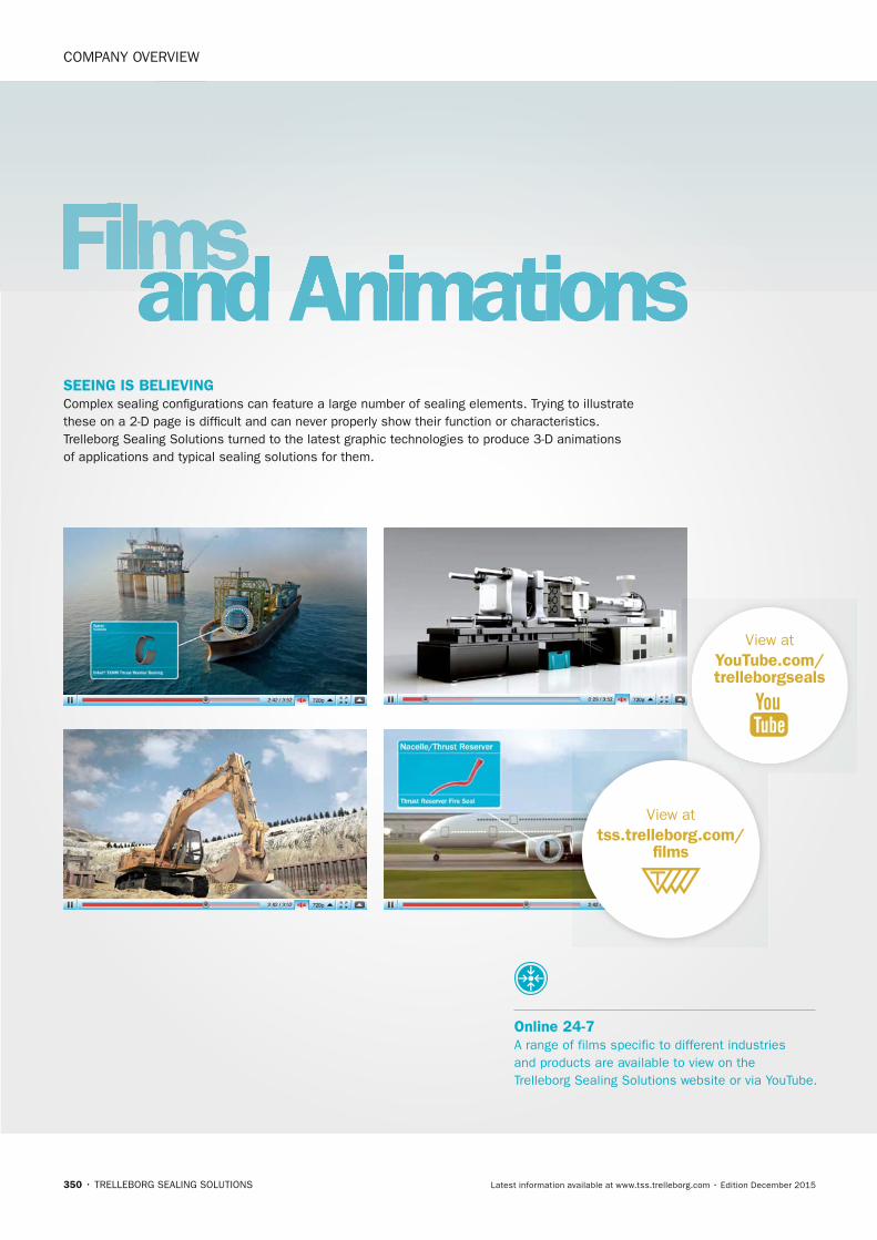
Filmsand Animationsand AnimationsFilmsand AnimationsFilms
View atyouTube.com/trelleborgseals
View attss.trelleborg.com/
films
Online 24-7A range of films specific to different industries and products are available to view on the Trelleborg Sealing Solutions website or via YouTube.
SEEInG IS BELIEVInG Complex sealing configurations can feature a large number of sealing elements. Trying to illustrate these on a 2-D page is difficult and can never properly show their function or characteristics. Trelleborg Sealing Solutions turned to the latest graphic technologies to produce 3-D animations of applications and typical sealing solutions for them.
COMPANY OVERVIEW
350 • TRELLEBORG SEALING SOLUTIONS Latest information available at www.tss.trelleborg.com • Edition December 2015
FBP_neues_Layout_2015.indb 350 17.10.2016 13:39:48

COMPANY OVERVIEW
TRELLEBORG SEALING SOLUTIONS • 351Latest information available at www.tss.trelleborg.com • Edition December 2015
FBP_neues_Layout_2015.indb 351 17.10.2016 13:39:57
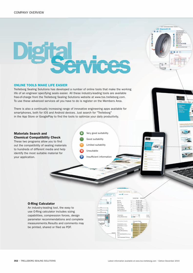
+
–
+?
OnLInE TOOLS MAKE LIFE EASIERTrelleborg Sealing Solutions has developed a number of online tools that make the working life of an engineer specifying seals easier. All these industry-leading tools are available free-of-charge from the Trelleborg Sealing Solutions website at www.tss.trelleborg.com. To use these advanced services all you have to do is register on the Members Area.
There is also a continually increasing range of innovative engineering apps available for smartphones, both for iOS and Android devices. Just search for "Trelleborg" in the App Store or GooglePlay to find the tools to optimize your daily productivity.
O-Ring CalculatorAn industry-leading tool, the easy to use O-Ring calculator includes sizing capabilities, compression forces, design parameter recommendations and complete measurements.Results and comments may be printed, shared or filed as PDF.
Materials Search and Chemical Compatibility Check These two programs allow you to find out the compatibility of sealing materials to hundreds of different media and help identify the most suitable material for your application.
DigitalDigitalServicesServicesServicesDigitalServicesDigitalDigitalServicesDigital
Very good suitability
Good suitability
Limited suitability
Unsuitable
Insufficient information
COMPANY OVERVIEW
352 • TRELLEBORG SEALING SOLUTIONS Latest information available at www.tss.trelleborg.com • Edition December 2015
FBP_neues_Layout_2015.indb 352 17.10.2016 13:40:09
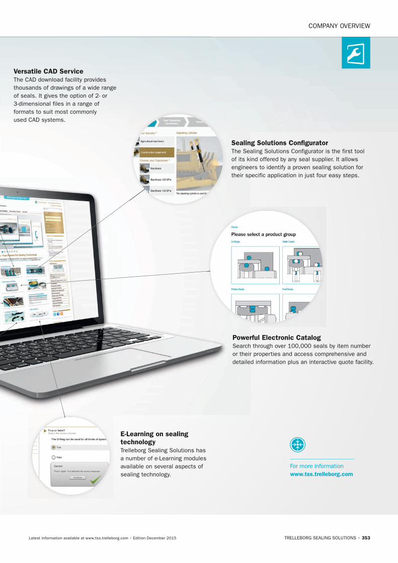
Sealing Solutions ConfiguratorThe Sealing Solutions Configurator is the first tool of its kind offered by any seal supplier. It allows engineers to identify a proven sealing solution for their specific application in just four easy steps.
Versatile CAD Service The CAD download facility provides thousands of drawings of a wide range of seals. It gives the option of 2- or 3-dimensional files in a range of formats to suit most commonly used CAD systems.
Powerful Electronic Catalog Search through over 100,000 seals by item number or their properties and access comprehensive and detailed information plus an interactive quote facility.
E-Learning on sealing technologyTrelleborg Sealing Solutions has a number of e-Learning modules available on several aspects of sealing technology.
For more information www.tss.trelleborg.com
COMPANY OVERVIEW
TRELLEBORG SEALING SOLUTIONS • 353Latest information available at www.tss.trelleborg.com • Edition December 2015
FBP_neues_Layout_2015.indb 353 17.10.2016 13:40:19

Mobile Appsand Servicesand ServicesMobile Appsand ServicesMobile AppsWe understand the needs of engineers on the go. Check out our latest mobile tools and apps, ranging from an O-Ring calculator to unit and hardness converters. Just search for "Trelleborg" in the App Store or Google Play to find the tools to optimize your daily productivity.
ISO Fits & Tolerances AppSimply enter the nominal
diameter and select the
tolerance classes for bore
and shaft to find the complete
ISO fits definition with all
relevant values including type
of fit, with handy graphs to
illustrate the classes by bore
and shaft.
Technical Glossary AppThis app provides definitions of more than 2,000 terms from the world of sealing technology and engineering.
Aerospace GrooveSelector AppThis app covers two of the most important SAE aerospace groove standards for hydraulic systems, AS4716 Rev B and AS5857 Rev A, making it really easy to find the size of grooves and hardware needed.
Installation Instructions AppVideos demonstrate thebest practice methods for installing seals, providing all relevant documentation within the interface, guiding you to a successful installation of Radial Oil Seals and Turcon® and Zurcon® rod and piston seals.
Unit & HardnessConverter AppIntuitive and very easy to use,simply select the dimension and enter the value for conversion. The app offers a wide range of engineering and scientific units for each dimension.
COMPANY OVERVIEW
354 • TRELLEBORG SEALING SOLUTIONS Latest information available at www.tss.trelleborg.com • Edition December 2015
FBP_neues_Layout_2015.indb 354 17.10.2016 13:40:22

HydraulicCylinder CalculatorQuickly calculate areas and volumes in cylinders, extraction and retraction forces, time velocity and outflow by entering the requisite dimensions and parameters of the cylinder. In compliance with ISO 3320, ISO 3321 and ISO 4393.
Tubing and Hose AppDeveloped specially for life sciences engineers, this app helps you to easily choose the correct tubing and hose based on material, pressure and dimensions, removing the need to search through catalogs.
Material Compability AppCross reference a wide variety of different materials with chemical environments to find the most effective compounds for your application. Select up to 20 materials at once to produce an easy to read compatibility chart with recommendations for use.
in the groove appOur in the groove magazine provides news, technical and product information on seals, as well as insights into the markets they are used in. The magazine is also available in print and as an interactive PDF.
For more information www.tss.trelleborg.com
O-Ring Calculator AppWhen a user enters installation specifications into the O-Ring Calculator app, such as the bore or rod/shaft diameter, the app quickly calculates O-Ring and housing dimensions in both metric and inch.
Available on theAPP STORE
MAny MORE APPS
available
Android App onGoogle Play
COMPANY OVERVIEW
TRELLEBORG SEALING SOLUTIONS • 355Latest information available at www.tss.trelleborg.com • Edition December 2015
FBP_neues_Layout_2015.indb 355 17.10.2016 13:40:32
356 • TRELLEBORG SEALING SOLUTIONS Latest information available at www.tss.trelleborg.com • Edition December 2015
Notes
FBP_neues_Layout_2015.indb 356 17.10.2016 13:40:32
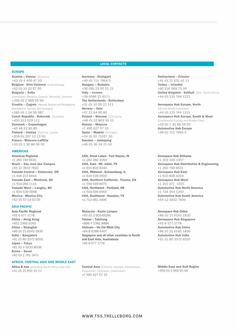
ISO 9001:2008 ISO/TS 16949:2009
Your Partner for Sealing Technology
Trelleborg Sealing Solutions is a major international developer, manufacturer and supplier of seals, bearings and molded components in polymers. We are uniquely placed to offer dedicated design and development from our market-leading product and material portfolio: a one-stop-shop providing the best in elastomer, silicone, thermoplastic, PTFE and composite technologies for applications in aerospace, industrial and automotive industries.
With 50 years of experience, Trelleborg Sealing Solutions engineers support customers with design, prototyping, production, test and installation using state-of-the-art design tools. An international network of over 70 facilities worldwide includes over 20 manu- facturing sites, strategically-positioned research and development centers, including materials and development laboratories and locations specializing in design and applications.
Developing and formulating materials in-house, we utilize the resource of our material database, including over 2,000
proprietary compounds and a range of unique products.Trelleborg Sealing Solutions ful�lls challenging service requirements, supplying standard parts in volume or a single custom-manufactured component, through our integrated logistical support, which effectively delivers over 40,000 sealing products to customers worldwide.
Facilities are certi�ed to ISO 9001:2008 and ISO/TS 16949:2009. Trelleborg Sealing Solutions is backed by the experience and resources of Trelleborg Group, one of the world’s foremost experts in polymer technology.
The information in this brochure is intended to be for general reference purposes only and is not intended to be a speci�c recommendation for any individual application.
The application limits for pressure, temperature, speed and media given are maximum values determined in laboratory conditions. In application, due to the interaction of operating
parameters, maximum values may not be achieved. It is vital therefore, that customers satisfy themselves as to the suitability of product and material for each of their individual
applications. Any reliance on information is therefore at the user‘s own risk. In no event will Trelleborg Sealing Solutions be liable for any loss, damage, claim or expense directly
or indirectly arising or resulting from the use of any information provided in this brochure. While every effort is made to ensure the accuracy of information contained herewith,
Trelleborg Sealing Solutions cannot warrant the accuracy or completeness of information.
To obtain the best recommendation for a specific application, contact your local Trelleborg Sealing Solutions marketing company.
This edition supersedes all previous brochures. This brochure or any part of it may not be reproduced without permission.
® All trademarks are the property of Trelleborg Group. The turquoise color is a registered trademark of Trelleborg Group. © 2015, Trelleborg Group. All rights reserved.
Lastest information available at www.tss.trelleborg.com ˙ Edition June 20152 ˙ TRELLEBORG SEALING SOLUTIONS
3023_TTS_FBPCatalog_CMYK_A4_v1.2.indd 2 14.04.2014 15:30:49
www.Tss.Trelleborg.com
LocaL contacts
EuropE
austria – Vienna (Slovenia) +43 (0) 1 406 47 33 Belgium - Dion-Valmont (Luxembourg)+32 (0) 10 22 57 50 Bulgaria – sofia (Azerbaijan, Belarus, Greece, Romania, Ukraine)+359 (0) 2 969 95 99 croatia – Zagreb (Albania, Bosnia and Herzegovina, Macedonia, Serbia, Montenegro)+385 (0) 1 24 56 387 czech republic - rakovnik (Slovakia)+420 313 529 111Denmark – copenhagen +45 48 22 80 80 Finland – Vantaa (Estonia, Latvia)+358 (0) 207 12 13 50 France - Maisons-Laffitte +33 (0) 1 30 86 56 00
Germany - stuttgart+49 (0) 711 7864 0 Hungary – Budaörs +36 (06) 23 50 21 21 Italy – Livorno +39 0586 22 6111 the netherlands - rotterdam +31 (0) 10 29 22 111 norway – oslo+47 22 64 60 80 poland – Warsaw (Lithuania)+48 (0) 22 863 30 11russia – Moscow +7 495 627 57 22 spain – Madrid (Portugal)+34 (0) 91 71057 30sweden – Jönköping +46 (0) 36 34 15 00
switzerland – crissier +41 (0) 21 631 41 11turkey – Istanbul+90 216 569 73 00 united Kingdom - solihull (Eire, South Africa)+44 (0) 121 744 1221
aerospace Hub Europe, north (UK and Nordic Countries) +44 (0) 121 744 1221aerospace Hub Europe, south & West (Continental Europe and Middle East) +33 (0) 1 30 86 56 00automotive Hub Europe +49 (0) 711 7864 0
aMErIcas
americas regional +1 260 749 9631Brazil – são José dos campos+55 12 3932 7600canada central – Etobicoke, on+1 416 213 9444canada East – Montreal, Qc+1 514 284 1114canada West – Langley, Bc+1 604 539 0098Mexico - Mexico city+52 55 57 19 50 05
asIa pacIFIc
asia pacific regional+65 6 577 1778china – Hong Kong+852 2366 9165china – shanghai+86 (0) 21 6145 1830India – Bangalore+91 (0) 80 3372 9000Japan – tokyo+81 (0) 3 5633 8008Korea – seoul+82 (0) 2 761 3471
usa, Great Lakes - Fort Wayne, In+1 260 482 4050usa, East - Mt. Juliet, tn+1 615 800 8340usa, Midwest - schaumburg, IL+1 630 539 5500usa, northern california - Fresno, ca+1 559 449 6070usa, northwest - portland, or+1 503 595 6565usa, southwest - Houston, tX+1 713 461 3495
aerospace Hub airframe+1 303 469 1357aerospace Hub Distribution & Engineering+1 260 749 9631aerospace Hub East +1 610 828 3209aerospace Hub West +1 310 371 1025automotive Hub north america+1 734 354 1250automotive Hub south america +55 12 3932 7600
Malaysia - Kuala Lumpur+60 (0) 3 90549266taiwan – taichung+886 4 2382 8886Vietnam – Ho chi Minh city+84 8 6288 6407singapore and all other countries in south and East asia, australasia+65 6 577 1778
aerospace Hub china +86 (0) 21 6145 1830aerospace Hub singapore +65 6 577 1778automotive Hub china +86 (0) 21 6145 1830automotive Hub India +91 (0) 80 3372 9200
aFrIca, cEntraL asIa anD MIDDLE East
africa & Iran (excluding South Africa (see UK))+41 (0) 21 631 41 11
central asia (Armenia, Georgia, Kazakhstan, Kyrgyzstan, Tajikistan, Uzbekistan)+7 495 627 57 22
Middle East and Gulf region +359 (0) 2 969 95 99
2 • TRELLEBORG SEALING SOLUTIONS Latest information available at www.tss.trelleborg.com • Edition December 2015
TRELLEBORG SEALING SOLUTIONS
YOUR PARTNER FOR SEALING TECHNOLOGY
PRODUCT CATALOG & ENGINEERING GUIDE
Food, Beverage & Pharmaceutical
Sealing Systems
3023_TTS_FBPCatalog_CMYK_A4_v1.2.indd 1 14.04.2014 15:30:43
Food, Beverage &
Pharm
aceutical Sealing S
ystems
© 2
01
5 T
relle
borg
Gro
up.
At t
ime
of p
ublic
atio
n th
e in
form
atio
n co
ntai
ned
in t
his
liter
atur
e is
bel
ieve
d to
be
corr
ect
and
accu
rate
.99G
BK
2B
RO
EE1215
www.Tss.Trelleborg.com
facebook.com/TrelleborgSealingSolutions
twitter.com/TrelleborgSeals
youtube.com/TrelleborgSeals
flickr.com/TrelleborgSealingSolutions
Trelleborg is a world leader in engineered polymer solutions that seal, damp and protect critical applications in demanding environments. Its innovative engineered solutions accelerate performance for customers in a sustainable way. The Trelleborg Group has local presence in over 40 countries around the world.