Embed Size (px)
Citation preview

FOR ELECTRICAL POWER, QUALITY MATTERSUnderstanding the basic issues of Power Quality and how to address them.

WHITE PAPER
2
FOR ELECTRICAL POWER, QUALITY MATTERS
IntroductionIf you own or run a business, it ’s very likely that one of the things you’re least likely to think about on a regular basis is the quality of your electricity supply. For a start, what is power quality and how can it vary? Surely you can depend upon your energy supplier to look after this sort of thing, and anyway, does power quality really matter or is it just something for specialist engineers to worry about? In this white paper we’re going to answer all of those questions, but let ’s start off by saying that power quality is most definitely a concern for us all.
Have you ever had a piece of equipment – most likely a computer or other electronic item – that misbehaved or even broke down regularly for no apparent reason?
Maybe you have lights that flicker, or if you operate a factory, motors that run hot and fail sooner than expected. All of these could be the results of poor power quality and if you don’t realise this, the time and money you spend on trying to fix the symptoms is likely to be wasted. And that ’s not all: power quality issues can also increase your energy bills, eating further into your hard-earned profits.
For these reasons, everyone who owns or runs a business needs to be aware of the basics of power quality, to understand how to assess it, and to know what to do if and when problems are identified. Or to put it another way, a few minutes spent reading this white paper could save you a lot of time, trouble and money!
What is power quality?First, let ’s make it clear that we’re only going to talk about AC supplies. This is because although DC supplies are possible, and were actually quite common until the middle of the 20th century, today’s network operators only offer AC supplies. DC supplies may make a comeback in the not-too-distant future because in the modern world they have certain benefits, but that ’s a topic for a different white paper!
In a perfect world, you would expect your network operator to provide you with an AC supply at a constant voltage, a fixed frequency, and with perfectly sinusoidal voltage and current waveforms that have no nasty ‘spikes’ on them. Also, if it ’s a three-phase supply, you would expect the voltages of the three phases to be exactly the same. This would be perfect power quality. However, as we don’t live in a perfect world, your supply may not actually meet these requirements and, even if it does meet them at the point it enters your premises, it may well become degraded as it passes through the electrical installations on your site.
As this suggests, if you have power quality issues, in many cases it ’s not the fault of your network operator. The operators do, in fact, go to great lengths to ensure that they deliver ‘clean’ supplies, but some of the factors that affect supply quality, such as thundetrstorms and the equipment you’ve got installed in your own premises, are beyond their control.
That said, what can possibly go wrong with power quality? In practice, almost all power quality issues can be divided into six main areas. These are: harmonics, dips and swells, transients (spikes), interference, voltage imbalance and poor power factor. In the remainder of this white paper, we’ll examine each of these issues in turn.

In
2 2 2
THDi = √(I2 + I3 + ... + I )1
33
HarmonicsAs was mentioned in the introduction, the voltage and current waveforms in an ideal power system would be perfectly sinusoidal and this would not be too difficult to achieve if all the loads connected to the power system were linear – that is, the loads where the current drawn from the supply is always proportional to the applied voltage. Simple heaters and incandescent lamps are examples of linear loads and, until the last few decades of the 20th century, loads were predominantly of this type.
Within the last 30 years, however, there has been a big increase in the number of non-linear loads connected to the electrical network. These include computers and associated IT equipment, uninterruptable power supplies, variable speed motor drives, electronic lighting ballasts and LED lighting, to name just a few. The growing use of such equipment, and the use of electronics to control nearly all types of electrical load, are beginning to have some worrying effects on the electricity supply and, in particular, on individual site installations. It is estimated that today over 95% of the harmonics present on a given site are generated by equipment installed on that site.
As we have stated, when a linear load is connected to the supply it draws a sinusoidal current at the same frequency as the voltage. Non-linear loads, however, draw currents that are not necessarily sinusoidal. In fact, the current waveform can become quite complex, depending on the type of load and its interaction with other components in the installation. Non-linear loads produce distorted current waveforms in the supply system, and in severe cases this can result in noticeably distorted voltage waveforms. The consequences can include significant energy losses, shortened equipment life and reduced operating efficiency of devices.
The distortion of the waveform produced by non-linear loads can be mathematically analysed to show that it is equivalent to adding components at integer multiples of the supply frequency to the ‘pure’ supply frequency waveform. That is, for a 50 Hz supply, the distortion takes the form of additional components at 100, 150, 200, 250, 300 Hz and so on – an example is shown in Figure 1.
Figure 1: A distorted waveform can be analysed as multiple sine waves added together.
These additional components are the harmonics, and in theory, they can go all the way up to infinity. In practice, however, it is rarely necessary to consider harmonics above say, the 50th, which has a frequency of 50 x 50 Hz = 2.5 kHz and, in most cases, only the lower order harmonics, up to the 25th, will be of importance. Unfortunately, unless they are prevented from doing so, harmonics from a non-linear load will propagate through the supply system causing problems elsewhere.Knowing that a distorted current waveform can always be represented as a series of superimposed sine waves (using a mathematical procedure known as Fourier analysis) makes it possible to devise a measure of the amount of harmonic distortion present in the current in a supply system. This is known as the total harmonic current distortion or THDi, and is calculated with this formula:
Where I 1 is the current at the supply frequency, I 2 is the current at twice the supply frequency, I 3 is the current at three times the supply frequency, and so on. Fortunately, it ’s unlikely that you will ever have to use this formula in practice, as modern instruments for analysing harmonics carry out all of the necessary calculations automatically and simply present you with the THDi figure.

4
Harmonic currents have negative effects on almost all items connected to an electrical system; they upset sensitive electronic devices, they increase heating and they produce mechanical stresses. Among the most common effects of harmonics are computers crashing, IT equipment locking up, lights flickering, electronic components failing in process control equipment, problems when switching large loads, overheating of neutral conductors, unnecessary circuit breaker tripping and inaccurate metering.
While some of these effects, such as flickering lights and IT equipment crashes, could be dismissed as no more than irritants, others such as process equipment failures, can lead to costly downtime. Worst of all are failures of power factor capacitors and electrical distribution equipment like cables, transformers, motors and standby generators. Here the replacement equipment is likely to be expensive and may only be available on a long lead time. In these cases, both the repair costs and the consequential costs can be enormous. And, even if there are no outright failures, the presence of harmonics will cause reduced electrical efficiency within the installation leading to excessive power consumption which you will be paying for.
The risk to power factor correction capacitors relates to the fundamental property of any capacitor: its impedance decreases as the frequency rises. At high frequencies, a capacitor can behave almost as a short circuit. Power factor correction capacitors are generally designed with operation at the fundamental supply frequency in mind, and the reduced impedance they present to higher frequency harmonic currents leads to increased current flow and increased heating, which may result in premature failure. Capacitors can also be permanently damaged if the parallel circuit they form with an associated transformer happens to be resonant at one of the harmonic frequencies.
Eddy current heating in motors and transformers is proportional to the square of the harmonic frequency, so it follows that as the presence of higher order harmonics in the supply system increases, the heating effect will increase even more dramatically. Not only does the generation of heat waste energy – which you are paying for – it also increases the risk of failures of or even fires in wiring, motors, transformers and other distribution equipment.
In addition to the losses that result from heating effects, harmonics in motors can give rise to the problematic phenomenon of torsional oscillation of the motor shaft. Torque in AC motors is produced by the interaction between the air gap magnetic field and induced currents in the rotor. When a motor is supplied non-sinusoidal voltages and currents, the air gap magnetic fields and the rotor currents will unavoidably contain harmonic frequency components.
+VE 1, 4, 7, 10, 13
-VE 2, 5, 8, 11, 14
Zero 3, 9, 15, 21
These are grouped into positive, negative and zero sequence components. Positive sequence harmonics (1, 4, 7, 10, 13, etc.) produce magnetic fields, and hence torque, rotating in the same direction as the field and torque produced by the fundamental frequency of the supply. Negative sequence harmonics (2, 5, 8, 11, 14, etc.)
55
produce magnetic fields and torque that rotate in the opposite direction. Zero sequence harmonics (3, 9, 15, 21, etc.) do not develop torque, but produce additional losses in the machine.
The interaction between the positive and negative sequence magnetic fields and currents produces the torsional oscillations of the motor shaft, which appears as shaft vibrations. If the frequency of these vibrations coincides with the natural mechanical frequency of the shaft, they become amplified and severe damage to the motor shaft may occur. It is sometimes possible to literally hear a transformer or motor ‘sing’ or ‘growl’ due to these vibrations and this is often one of the first observed indications of a harmonic problem.
Some of the most troublesome harmonics are the 3rd, and odd multiples of the 3rd, i.e. the 9th, 15th etc. These harmonics are called “triplens”. The triplen harmonics on each of the supply phases are in phase with each other so they add rather than cancel in the neutral conductor of a three-phase four-wire system. This can overload the neutral conductor if it has not been sized to allow for the potential presence of harmonics.
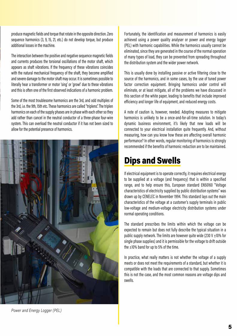
Power and Energy Logger (PEL)
Fortunately, the identification and measurement of harmonics is easily achieved using a power quality analyser or power and energy logger (PEL) with harmonic capabilities. While the harmonics usually cannot be eliminated, since they are generated in the course of the normal operation of many types of load, they can be prevented from spreading throughout the distribution system and the wider power network.
This is usually done by installing passive or active filtering close to the source of the harmonics, and in some cases, by the use of tuned power factor correction equipment. Bringing harmonics under control will eliminate, or at least mitigate, all of the problems we have discussed in this section of the white paper, leading to benefits that include improved efficiency and longer life of equipment, and reduced energy costs.
A note of caution is, however, needed. Adopting measures to mitigate harmonics is unlikely to be a once-and-for-all-time solution. In today’s dynamic business environment, it ’s likely that new loads will be connected to your electrical installation quite frequently. And, without measuring, how can you know how these are affecting overall harmonic performance? In other words, regular monitoring of harmonics is strongly recommended if the benefits of harmonic reduction are to be maintained.
Dips and SwellsIf electrical equipment is to operate correctly, it requires electrical energy to be supplied at a voltage (and frequency) that is within a specified range, and to help ensure this, European standard EN50160 “Voltage characteristics of electricity supplied by public distribution systems” was drawn up by CENELEC in November 1994. This standard lays out the main characteristics of the voltage at a customer ’s supply terminals in public low-voltage and medium-voltage electricity distribution systems under normal operating conditions.
The standard prescribes the limits within which the voltage can be expected to remain but does not fully describe the typical situation in a public supply network. The limits are however quite wide (230 V ±10% for single phase supplies) and it is permissible for the voltage to drift outside the ±10% band for up to 5% of the time.
In practice, what really matters is not whether the voltage of a supply meets or does not meet the requirements of a standard, but whether it is compatible with the loads that are connected to that supply. Sometimes this is not the case, and the most common reasons are voltage dips and swells.

Dip Swell
6
What are voltage dips and swells?A voltage dip, which is also sometimes called a voltage sag, is a sudden reduction in the supply voltage of between 10% and 90%, which lasts for between 10 ms and 1 minute. The depth of a voltage dip is defined as the difference between the minimum RMS voltage during the dip and the declared supply voltage. Voltage changes that reduce the supply voltage by less than 10% are not considered to be dips.
Voltage dips may be caused by external factors on the supply network or internal factors within an installation. They can be single events that occur at random, or a series of events that repeat in some sort of pattern. In all instances, monitoring and recording the supply voltage over time will show exactly what is happening and help to locate the cause.
External factors are more likely to produce single events and include load switching and fault clearance in the supply network. A similar effect can occur when switching between the mains supply and uninterruptible power supplies or emergency back-up generators. Common causes of voltage dips within an installation are the switching of large loads, such as motors, arc furnaces and welding equipment, and the operation of loads with fluctuating current demands. Often voltage dips produced within an installation occur at regular intervals or at particular times.
The effect that dips have on electrical equipment and building occupants varies widely and is dependent on the factors that include the nature of the event and the type of equipment connected to the supply system. In an office lit by fluorescent luminaires, which uses equipment with
switch-mode power supplies and has a UPS system, it is perfectly possible that even quite severe dips will pass unnoticed. However, a similarly equipped office with a different type of lighting, older equipment with linear power supplies and no UPS, might well experience considerable disruption.
Supply voltage dips can cause particular problems, with varying degrees of severity, for AC induction motors. As the supply voltage to the motor decreases, its speed tends to decrease. Depending on the depth and the duration of the voltage dip, the motor may return to its normal speed when the supply voltage recovers. If the magnitude of the dip or its duration exceed certain limits, however, the motor may stall, or it may be disconnected from the supply by a contactor dropping out or the operation of an under-voltage trip. For motors fed from a variable speed drive, the drive may shut down to prevent potential motor damage.
Voltage swells are the opposite of dips and are defined as a sudden increase in the supply voltage of 10% or greater for a short period, after which the voltage returns to its normal value. Once again, the time period for a swell is generally taken to be between 10 ms and 1 minute. Swells are almost always caused by a large load being switched ff somewhere on the power supply network or in the local installation.
Although the effects of dips may be more noticeable, voltage swells are often more destructive. Regular and sustained voltage swells can cause insulation degradation in induction motors because of the increases in current flow and heat generation, with this degradation ultimately leading to premature failure of the motor. Swells can also cause breakdown of components in power supplies due to cumulative overload effects, and damage to electronic equipment, which is often sensitive to overvoltage.

Transients (Spikes)
Burst
77
Fortunately, there are ways to mitigate the effects of dips and swells but an essential first step is always to locate the cause of the problem. This is achieved by conducting a site survey, which involves moving around the electrical installation, measuring current and voltage at various locations and using this information to identify the source of the dips and swells.
Site surveys are most easily performed with a modern power and energy logger (PEL) or power quality analyser. These instruments can be connected quickly and non-intrusively to distribution boards and other key points within the installation and left in place to gather and record information. In many cases, there is no need to even turn the power off while connecting the instrument.
If monitoring shows that the problems are coming from the external supply, and voltage limits laid down for the public supply are being exceeded, then it ’s time to call your electricity supplier. However, in many cases the source of the problem will be found to be within your own installation and, once you’ve identified the equipment causing the dip or swell, you can start to consider remedies.
These might, for example, include supplying the equipment in question from a dedicated circuit, installing a UPS or, in the case of motors, fitting a soft start or variable speed drive to reduce sudden changes in the current the motors draws from the supply during starting. If these remedies prove impractical or ineffective, it may again be time to call your electricity supplier to see whether a more resilient service can be provided.
Variable Speed Drive
TransientsTransients – which are often called spikes – can have an effect on equipment and installations that ranges from mildly irritating to extremely damaging and costly. An electrical transient is a very fast, short duration spike in voltage that can be several kV in magnitude. It may be a single event, but transients can also come in bursts. The voltage spike produces an increase in current in the load, seen as a current spike, which results in a momentary increase in the energy transferred from the supply to the load. Depending on the magnitude and duration of the transient, the amount of extra energy transferred in this way may be of little or no consequence, or it may be enough to cause serious damage.
It is often assumed that most transients are generated by events external to the installation that ’s affected, such as lightning strikes, load switching and fault clearance in the utility company’s supply equipment. It is true that because of their high voltages and energy content, transients produced by lightning pose the highest risk of equipment damage and failure, but most transients – more than 80%, studies have shown – are in fact generated within the installation itself.
Lightning induced transients are rare, so why are they potentially so damaging? The current in a typical lightning strike rises quickly to its maximum level within 1 to 10 microseconds, then it decays more slowly in around 50 to 200 microseconds. This rapidly changing current creates electromagnetic radiation (radio waves) that travels outward from the location of the strike. If this radiation encounters an electrical conductor, such as a power

8
line, a communication line or a metallic pipe, the conductor acts like an aerial and a high voltage – the transient – is induced into it. Note that the conductor doesn’t have to be struck directly by the lightning; even a strike to the ground near to the conductor can induce large transients.
Other external factors like load switching and fault clearance within the utility supply can generate transients. Load switching transients result from the sudden release of electrical, magnetic, or in the case of rotating machines, mechanical energy stored in a device at the instant it is switched on or off. Transients produced by fault clearance are produced by a similar sudden release of energy at the instant the fault current is interrupted. Transients from these external sources are comparatively rare and are almost always much smaller than those produced by lightning.
A much more frequent source of transients is load switching within an installation. The event that gives rise to the transient could be something like bus transfer switching, but it is even more likely to be something
simple like a circuit breaker or a contactor opening or closing. Even operating a light switch can create transients and, in every case, the level of transients will be increased if the switching device has faulty or corroded contacts. Office equipment, such as photocopiers and laser printers, is notorious for generating transients, as are HVAC systems. In fact, whenever an inductive or capacitive load is switched on or off, it will almost certainly produce a transient – albeit a small one, in most cases – that propagates through the electrical installation.
When considering the effect that spikes have on an electrical installation and the equipment connected to it, it is generally the case that the transients generated internally within the installation, which are usually small, are likely to cause slow degradation over time. The much larger transients produced by lightning and the switching of large inductive loads can, however, cause immediate insulation breakdown and subsequently deliver large amounts of energy into the equipment, resulting in failure and, in the worst cases, fire or even an explosion.
The mechanism of these dramatic failures is that when equipment is subjected to a transient that has a voltage higher than the breakdown voltage of the equipment ’s insulation, a flashover is likely to occur. This flashover is a low impedance electric arc through which current from the supply system can flow. With all of the energy of the mains supply behind it, the strength of the arc and the heat it produces increase almost without limit, creating the risk of fire, explosion and danger to life.
Selbst wenn Transienten nicht zu Hardware-Beschädigungen führen , können sie völlig unerwartet bei Computern Programmabstürze und Datenverluste verursachen, Prozesssteuerungen lahmlegen und Fehler-strom-Schutzschaltungen auslösen.Es gibt eine große Anzahl von Schutzmaßnahmen gegen Transienten und bei der Auswahl der bestgeeigneten Maßnahme sollte man Spannungshöhe, Dauer und Leistung der zu erwartenden Transienten, sowie die Art der zu schützenden Geräte beachten. Elektromotoren zum Beispiel können so konstruiert sein, dass sie Transienten eines typischen Versorgungsnetzes ohne Schutz klaglos überstehen, aber man sollte
Traditional electrical equipment is likely to suffer damage only if exposed to large and/or high energy transients, but electronic equipment is much more sensitive and, unless protected, it can be irreparably damaged by comparatively small transients. This is because microcontrollers and similar components rely on tiny, almost vanishingly thin areas of silicon to insulate them, and such insulation can be damaged by overvoltages that would go completely unnoticed in traditional equipment. It ’s worth noting that transient damage to electronic devices doesn’t necessarily result in immediate failure but may reveal itself as apparently random failure at some future time. Given the present-day reliance of almost

99
every aspect of commerce, business and manufacturing on electronic systems, such failures are a real concern, leading as they so often do to costly downtime and consequential costs.
Even when transients do not lead to equipment failure, they can still be disruptive causing computers to crash and lose data, for example, process control systems to shut down unexpectedly and even residual current devices (RCDs) to trip for no obvious reason.
A wide range of measures is available for providing protection against transients, and selection of the most appropriate type must take into account the voltage, duration and power level of the transients, and the type of equipment that is to be protected. Some types of equipment, such as motors may be designed to withstand transients on a typical supply system without further protection, but this should never be taken for granted. Electronic equipment may also feature integral protection, but this is unlikely to be adequate on its own if no other form of protection is fitted to the distribution system of the premises in which it is being used.
It may at first seem unnecessary to provide transient protection for test equipment like multimeters and multifunction installation testers but, in reality, such protection is essential. An electrical installation is just as likely to experience transients while tests are being carried out as at any other time and if the energy released as a result of the transient is enough to destroy an unprotected instrument, the user, who is likely to be close to it or even holding it, may well be injured or worse.
The need for transient protection in instruments is reflected in BS EN 61010, “Safety requirements for electrical equipment for measurement, control, and laboratory use”. This requires test equipment to be able to withstand levels of transients appropriate to the point in the installation where the instrument will be used. (See table)
BSEN61010-1 Transient Overvoltage Tests
Supply VoltageTransient Overvoltage
CAT I CAT II CAT III CAT IV150 V 800 V 1500 V 2500 V 4000 V300 V 1500 V 2500 V 4000 V 6000 V600 V 2500 V 4000 V 6000 V 8000 V1000 V 4000 V 6000 V 8000 V 12 000 V
BS EN 61010 recognises that externally generated transients will be at their most severe at the point where the supply enters the building and will gradually reduce in magnitude as they travel through the electrical installation, because of the inductance, capacitance and resistance of the wiring and other equipment. Put simply, this means that instruments connected at the point of supply need to be able to withstand transient voltages higher than instruments designed to be connected to fixed wiring within the installation, which in turn need to be able to withstand higher transient voltages than instruments that will be used solely on equipment plugged into socket outlets. This is summarised in the category (CAT) ratings shown in the table.
CAT I rated instruments can be used for measurements performed on secondary circuits not directly connected to mains. CAT II instruments are suitable for measurements performed on items connected to a standard 230v mains socket. CAT III instruments suitable for measurements performed on the fixed wiring within a building installation, which includes, for example, distribution boards, circuit- breakers, bus-bars, junction boxes and industrial equipment. CAT IV instruments can be used for measurements performed at the source of the low voltage installation.
Since instruments with a particular category rating can also be used in lower category applications – a CAT IV instrument can be used in any location within a low-voltage installation – it is often worthwhile investing in instruments with a high CAT rating since this will reduce the risk of an unsuitable instrument being used to carry out a particular task.
Transients can be mitigated using surge protection devices (SPDs), which are designed to prevent voltage spikes and surges damaging the installation wiring, infrastructure and equipment. If an overvoltage occurs, the SPD diverts the resulting excess current flow to earth and limits the voltage to a predetermined maximum value. Depending on circumstances, SPDs can be installed close to the internal source of the transients, close to the loads that need protection, or both.
Three types of SPD are currently available. Type 1 SPDs can discharge partial lightning currents and are used in buildings that are supplied via overhead lines or that have a roof- mounted lightning protection system in line with BS EN 62305. Type 2 SPDs are suitable for use in all other types of installation and are often installed at the incoming supply point and/or in sub-distribution boards. Type 3 SPDs have a low discharge capacity and are used to provide localised protection for sensitive equipment. In most

10
instances, they should only be used to supplement protection provided by Type 2 devices. Much more detailed information on the selection and application of SPDs is available on the manufacturers’ websites and reference should also be made to the latest edition of the IET Wiring Regulations (BS 7671) which now includes a section devoted to surge protection and SPDs.
To decide whether your installation is experiencing problems created by transients, the first action is to use a power quality analyser and, since transients are almost always intermittent, this needs to be equipped with data logging functionality so that recordings can be made over appropriately long periods of time. A good analyser will allow limits and alarms to be set to alert you when a significant transient has been detected, and you can then examine the data stored by the instrument to gain further information about the form and duration of the transient. This information is invaluable in determining the source.
Power Quality Analyser
Electrical InterferenceElectrical interference is more formally known as either electromagnetic interference (EMI) or radio frequency interference (RFI). If we’re being pedantic, EMI is the more general term because, strictly speaking, RFI applies only to interference over the band of frequencies used for radio transmissions. However, for our purposes, the two terms are interchangeable and in the remainder of this section we’ll simply refer to EMI.
EMI is generally much less harmful than transients. Its effect is typically to make equipment malfunction temporarily rather than to cause permanent damage. Nevertheless, equipment malfunctions
are often costly and disruptive, so EMI is not a trivial matter. EMI can come from a variety of sources including radar, TV, radio, mobile phone and microwave transmitters, and from less obvious external sources such as solar magnetic storms and radio signals produced by distant thunderstorms. External EMI can enter an electrical installation by electromagnetic induction, electrostatic coupling or conduction. EMI can also be generated by equipment within an installation, although modern appliances and equipment should be manufactured in compliance with electromagnetic compatibility (EMC) standards that minimise the risk of EMI generation.
Power and lighting equipment is unlikely to be directly affected by EMI, although electronic devices used to control this equipment may be susceptible. EMI is most often experienced as noise or hiss on audio equipment and as picture disturbances on television screens. Other common effects that are less immediately apparent include degradation of the performance of data networks and even completely stopping these networks from functioning. This can lead to increased error rates and potentially total loss of data. It ’s important to note that EMI can be transmitted by crosstalk between cables that run close together. For this reason, care should always be taken to segregate power and data cables and, where appropriate, to use screened cables.
A wide variety of products are available to block EMI and prevent it from entering equipment. These include EMI suppression filters and AC line filters, as well as ferrite cores and microwave absorbers. Such devices are only effective against conducted EMI. Efficient shielding – enclosing sensitive equipment in an earthed conductive box – is the best precaution against radiated and induced EMI, so for a complete solution a combination of shielding and filtering is required.
Voltage ImbalanceVoltage imbalance is a power quality issue that often receives little or no attention. This is very unfortunate because, as we shall see, an unbalanced supply can have serious consequences. Of course, if your business only has single-phase loads, imbalance isn’t an issue for you, and you can safely skip this section. If you have any three-phase loads however, you would be well advised to read on!
In a balanced three-phase ac power system, the voltages in all three of the phases are equal in magnitude and the phases are 120 degrees apart. In an unbalanced system, the phase voltages are not equal, and/or the phases are not 120 degrees apart. Voltage imbalance is more common than a phase shift and is

1111
typically caused by big single-phase loads, such as EV charge points, induction furnaces and some traction systems.
These single-phase loads may be connected between one of the phases and the supply neutral, when they draw power from just one of the three phases, or they may be connected between two phases, when they draw power from two of the three phases.
Winding damage caused by voltage imbalance
Either way, the three phases are loaded unequally and the voltage on the phase or phases that are heavily loaded will drop. This voltage reduction will be seen as voltage imbalance by all other items of equipment that are connected to the same supply system.Uneven distribution of even quite small single-phase loads across a three-phase system can, if there is enough of them, cause a slight voltage imbalance. This situation often develops over time when extra circuits are added to an installation that was originally balanced during its construction. Unequal degradation of power factor correction capacitors in a bank or even complete failure of one or more of the capacitors is another source of imbalance, and temporary imbalances can be produced by a fault on one of the phases either within the facility or further back up the supply network.
Having balanced phase voltages is arguably one of the most important requirements for an industrial installation, particularly if it uses three-phase motors, and crucially if they are operating at or near their full load capacity. With a fully loaded motor, unbalanced voltages at motor terminals can cause a percentage phase current imbalance up to 10 times the percentage voltage imbalance. This means that motors operating on unbalanced supplies must be significantly de-rated, even if the voltage imbalance appears to be relatively minor. Imbalance can also
make it necessary to de-rate power cables because of increase 2d I R losses.According to the IEC, voltage unbalance is defined as the ratio of negative sequence voltage to the positive sequence voltage. Briefly explained, the three phase voltages can be mathematically expressed as a sum of positive, negative and zero sequence components. Positive sequence voltages create a magnetic flux within the motor that rotates in the direction that the motor is intended to rotate, while negative sequence voltages create a flux that rotates in the opposite direction. Since the positive sequence voltages are always much greater than the negative sequence voltages (provided that the motor has been connected up correctly!) the direction of rotation of the motor is not affected.The counter rotating flux caused by negative sequence voltages creates additional heating in the motor windings that may eventually lead to insulation breakdown and premature motor failure. Continuous operation at 10° C above the recommended operating temperature can reduce the life of a rotating machine by a factor of two, and reduced motor operating life is almost always disruptive and expensive. The importance and prevalence of this problem is confirmed by the large number of businesses that develop and manufacture devices to monitor voltage imbalance as an aid to protecting motors.As well as the motors themselves, many solid-state motor controllers and inverters include components that are sensitive to voltage imbalance. Depending on the product, some of these will protect themselves and the motor by shutting down if they detect a significant voltage imbalance but, while this safeguards the equipment, the resulting disruption can still be costly. In less sophisticated products that don’t automatically shut down, voltage imbalances are a common cause of reduced life of front-end diodes and bus capacitors. Uninterruptible power supplies (UPSs) and inverter supplies also operate with reduced efficiency when presented with unbalanced supply voltages, often producing increased ripple on the DC output and, in many cases, increased harmonic currents in the supply system.Since voltage imbalance can have so many harmful effects, it ’s not surprising that it is covered by national and international standards. IEC 60034-1, for example, imposes a 1% negative phase sequence voltage limit on the supply feeding machines. However, EN 50160 states that imbalances of up to 3% can be expected, and indicates that an acceptable supply system standard is that “under normal operating conditions, during each period of one week, 95% of the 10-minute mean rms values of the negative phase sequence component of the supply voltage shall be within the range 0 to 2% of the positive phase sequence component”.
12
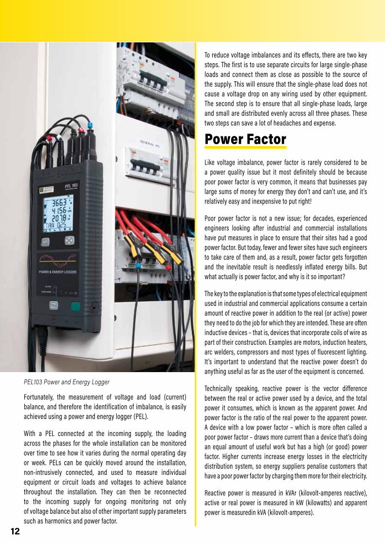
PEL103 Power and Energy Logger
Fortunately, the measurement of voltage and load (current) balance, and therefore the identification of imbalance, is easily achieved using a power and energy logger (PEL).
With a PEL connected at the incoming supply, the loading across the phases for the whole installation can be monitored over time to see how it varies during the normal operating day or week. PELs can be quickly moved around the installation, non-intrusively connected, and used to measure individual equipment or circuit loads and voltages to achieve balance throughout the installation. They can then be reconnected to the incoming supply for ongoing monitoring not only of voltage balance but also of other important supply parameters such as harmonics and power factor.
To reduce voltage imbalances and its effects, there are two key steps. The first is to use separate circuits for large single-phase loads and connect them as close as possible to the source of the supply. This will ensure that the single-phase load does not cause a voltage drop on any wiring used by other equipment. The second step is to ensure that all single-phase loads, large and small are distributed evenly across all three phases. These two steps can save a lot of headaches and expense.
Power Factor Like voltage imbalance, power factor is rarely considered to be a power quality issue but it most definitely should be because poor power factor is very common, it means that businesses pay large sums of money for energy they don’t and can’t use, and it ’s relatively easy and inexpensive to put right!
Poor power factor is not a new issue; for decades, experienced engineers looking after industrial and commercial installations have put measures in place to ensure that their sites had a good power factor. But today, fewer and fewer sites have such engineers to take care of them and, as a result, power factor gets forgotten and the inevitable result is needlessly inflated energy bills. But what actually is power factor, and why is it so important?
The key to the explanation is that some types of electrical equipment used in industrial and commercial applications consume a certain amount of reactive power in addition to the real (or active) power they need to do the job for which they are intended. These are often inductive devices – that is, devices that incorporate coils of wire as part of their construction. Examples are motors, induction heaters, arc welders, compressors and most types of fluorescent lighting. It ’s important to understand that the reactive power doesn’t do anything useful as far as the user of the equipment is concerned.
Technically speaking, reactive power is the vector difference between the real or active power used by a device, and the total power it consumes, which is known as the apparent power. And power factor is the ratio of the real power to the apparent power. A device with a low power factor – which is more often called a poor power factor – draws more current than a device that ’s doing an equal amount of useful work but has a high (or good) power factor. Higher currents increase energy losses in the electricity distribution system, so energy suppliers penalise customers that have a poor power factor by charging them more for their electricity.
Reactive power is measured in kVAr (kilovolt-amperes reactive), active or real power is measured in kW (kilowatts) and apparent power is measuredin kVA (kilovolt-amperes).

1313
Speaking less technically, this scenario can be made easier to understand by likening it to beer! If you order a pint of draught beer, the whole glass you pay for is equivalent to the apparent power. But take a closer look – that beer has got a frothy head on it! The beer is the part you really want, and that ’s equivalent to the active power, while the head, which makes no contribution to your refreshment, is equivalent to reactive power. A pint glass full of beer, with no head, would represent a power factor of 1 with no reactive power at all. In reality, that ’s usually impossible to achieve and a power factor of 0.95 (corresponding to less than 5% froth!) or better is usually considered acceptable.
So far, so good, but if electrical equipment inherently consumes active power, what can be done about it? Fortunately, it is possible to correct for power factor by adding, logically enough, a power factor correction (PFC) system. This usually takes the form of capacitors connected at the main distribution board, or sometimes at other locations.
Many sites will already have some form of PFC but, as implied earlier, it is not quite a fit-and-forget solution. If more equipment is installed on a site, or the type of equipment used on the site is significantly changed, the PFC system may no longer be adequate. It ’s also worth noting that capacitors used for PFC can degrade over many years of service and may eventually need to be replaced.In fact, according to The Carbon Trust it is not uncommon for industrial installations to be operating with high levels of reactive power giving power factors of between 0.7 and 0.8. This is surprising and totally unnecessary since measuring power factor is not at all difficult. It can be readily measured using portable test instruments, or alternatively, can be permanently monitored in real-time with
constantly displayed values, along with a multitude of other useful parameters including voltage, current and energy consumption.While specification of a PFC system to reduce reactive power requires knowledge of several factors including the voltage level and typical usage of the reactive loads on-site, the usage profile across the site, and the power quality required by the on-site loads, all of these are easily measured and/or calculated. And a properly designed PFC system will be a fraction of the cost of the savings it delivers.The simplest form of PFC involves fitting capacitors, but it is worth shopping around and taking expert advice to find a system that will accurately suit your particular requirements. If a single machine has a poor power factor, capacitors can be connected in parallel with it, so that they compensate for the poor power factor whenever the machine is switched on. Alternatively, if the power factor of a site is permanently poor and no single item of equipment is solely responsible, fixed PFC can be connected across the main power supply to the premises.In more complex applications, where many machines are switched on and off at various times, the power factor may be subject to frequent change. In this case the amount of PFC needs to be controlled automatically by switching banks of capacitors into and out of circuit, as required. And in facilities with large non-linear loads, with their associated harmonic currents, it may be necessary to use a de-tuned PFC system. Numerous solutions are available on the market to provide such functionality, but expert advice should always be sought if you are in any doubt.

1414
An eye for qualityWe at Chauvin Arnoux hope that this white paper has succeeded in demystifying the sometimes complex subject of power quality, and explained why we consider it to be so important. If you’re a typical business owner or manager, there’s absolutely no doubt that you pay great attention to the quality of products and services you buy for your business, and it should be the same for power and energy. After all, energy bills are probably a significant part of your outgoings.
We’ve shown that power quality can be degraded in many ways, and such degradation often has inconvenient and costly consequences. Just as important, however, we’ve shown that power quality problems are easy to detect – with the right equipment, of course – and that in most cases, once the problems have been identified, convenient and affordable solutions are available.
We’ve tried to present the information in this white paper as clearly as possible but there’s no doubt that power quality can be a daunting topic! So, if you’d like further information about the ideas we’ve put forward, or if you’d like help with starting your own power quality investigations, please get in touch with us. It costs nothing to talk to Chauvin Arnoux, but it can make a big difference to your costs and profitability!
Julian Grant

DP4
161 -
GB
- FM
FRANCEChauvin Arnoux12-16 rue Sarah BernhardtAsnières sur SeineTél : +33 1 44 85 44 85Fax : +33 1 46 27 73 [email protected]
Middle East Chauvin Arnoux Middle East P.O. BOX 60-154 1241 2020 JAL EL DIB -LEBANON Tel: +961 1 890 425 Fax: +961 1 890 424 [email protected] www.chauvin-arnoux.com
UNITED KINGDOM Chauvin Arnoux LtdUnit 1 Nelson Ct, Flagship Sq, Shaw Cross Business Pk Dewsbury, West Yorkshire - WF12 7TH Tel: +44 1924 460 494 Fax: +44 1924 455 328 [email protected] www.chauvin-arnoux.com