Embed Size (px)
Citation preview
STUDY ON
EMISSION CONTROL TECHNOLOGY
FOR HEAVY-DUTY VEHICLES
FINAL REPORT VOLUME 3
DEVELOPMENT OF ON BOARD DIAGNOSTICS SYSTEMS
CONTRACT N° ETD/00/503430 Study prepared for the European Commission – DG ENTR (Enterprise)
Joint effort by
MIRA Ltd, United Kingdom
PBA, United Kingdom
LAT/AUTh, Greece
TU Graz, Austria
TNO Automotive, Netherlands
Vito, Belgium
May 2002
EC-DG ENTR Emission control technology for heavy-duty vehicles ETD/00/503430
Volume 3 Development of on board diagnostics systems Page 2
This part of the project was carried out by
Graz
University of Technology
Institute for
Internal Combustion Engines and
Thermodynamics
Inffeldgasse 25
8010 Graz
Austria
Dieter Engler
Tel. 43 316 873 8098
Fax 43 316 873 8080
Stefan Hausberger
Tel. 43 316 873 7714
Fax 43 316 873 8080
EC-DG ENTR Emission control technology for heavy-duty vehicles ETD/00/503430
Volume 3 Development of on board diagnostics systems Page 3
0 CONTENTS
0 Contents .......................................................................................................................................3
1 Executive Summary....................................................................................................................5
2 Introduction ................................................................................................................................7
2.1 Objectives ..............................................................................................................................8
2.2 Background............................................................................................................................8
3 Approach .....................................................................................................................................9
4 On board Diagnostics (OBD) - General..................................................................................10
5 Comparison of OBD regulations .............................................................................................12
5.1 US Fact Finding Tour ..........................................................................................................14
6 Overview on OBD Requirements ............................................................................................15
7 Emission Control Systems........................................................................................................16
7.1 Diesel Particulate Filter (DPF) ............................................................................................16
7.1.1 Continuously Regenerating Trap (CRTTM, Johnson Matthey) .................................................17
7.1.2 Fuel-Born Catalysed Filter .......................................................................................................18
7.1.3 Fuel Burner Regenerating Filter ...............................................................................................19
7.1.4 Catalysed Diesel Particulate Filter (CDPF)..............................................................................19
7.1.5 Diesel Particulate Filters - Detection of the malfunctions........................................................19
7.2 NOx adsorbers ......................................................................................................................22
7.2.1 Selective Catalytic Reduction (SCR)........................................................................................22
7.2.2 DeNOx (Lean NOx) Catalyst .....................................................................................................23
7.2.3 NOx adsorbers - Detection of the malfunctions ........................................................................23
7.3 Low Pressure Fuel System...................................................................................................24
7.4 Injection Systems.................................................................................................................25
7.4.1 Distributor Injection Pump .......................................................................................................25
7.4.2 Electronic Unit Injector (EUI) + Electronic Unit Pump (EUP)................................................26
EC-DG ENTR Emission control technology for heavy-duty vehicles ETD/00/503430
Volume 3 Development of on board diagnostics systems Page 4
7.4.3 Common Rail Injection system ................................................................................................27
7.4.4 Injection Systems - Detection of the Malfunctions ..................................................................28
7.5 Exhaust Gas Recirculation (EGR) .......................................................................................29
7.5.1 High pressure EGR...................................................................................................................29
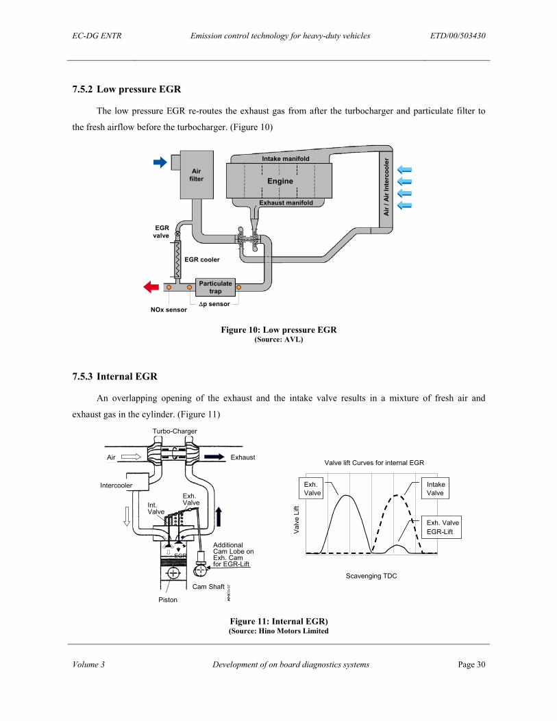
7.5.2 Low pressure EGR....................................................................................................................30
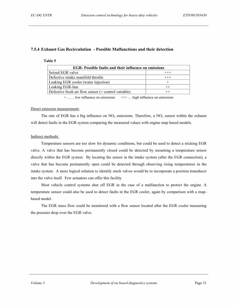
7.5.3 Internal EGR.............................................................................................................................30
7.5.4 Exhaust Gas Recirculation - Possible Malfunctions and their detection .................................31
8 Summary OBD..........................................................................................................................32
9 Fault Storage and enhanced function of OBD .......................................................................35
10 On-Board Monitoring (OBM) .................................................................................................38
11 Conclusions................................................................................................................................40
12 Recommendations.....................................................................................................................42
13 References..................................................................................................................................45
14 List of Abbreviations – Acronyms ..........................................................................................46
15 Annexes......................................................................................................................................49
15.1 Annex I ............................................................................................................................49
15.2 Annex II ...........................................................................................................................53
EC-DG ENTR Emission control technology for heavy-duty vehicles ETD/00/503430
Volume 3 Development of on board diagnostics systems Page 5
1 EXECUTIVE SUMMARY
To ensure the early detection of malfunctioning emission control components an on board diagnostics
(OBD) system is to be introduced into the EU legislation for heavy duty engines. Ideally emissions should be
measured in the vehicle exhaust, however this is unlikely to be feasible in the near-term because the sensors
are neither available nor proven to be robust and durable for truck applications. Thus the functionality of the
critical systems, that is EGR, fuel injection and DPF and SCR devices will have to, in general, be monitored
indirectly.
DPFs can be monitored by measuring the pressure differential across the filter and the exhaust gas
flow. These measurements will also be necessary for controlling the filter regeneration strategy.
Additionally, temperature sensors should detect overheating which could damage the filter.
For SCR both the exhaust temperature -required to control the urea injection- and the level of the urea
in the tank have to be monitored. To detect other potential malfunctions such as inadequate urea dosing and
damage to the catalyst, the use of NOx and ammonia (NH3) sensors seem to be the best approach. Although
SCR is a robust technology, the monitoring of the system is very critical. These sensors are not in series
production for truck applications, their durability is unproven, and they are likely to be expensive.
The general functionality of the fuel injection system may be monitored by measuring the regularity of
the angular velocity of the crankshaft. The necessary sensors are available and have a good performance at
engine speeds below 1500 rpm. Other possibilities include the use of wideband lambda and air mass sensors
or map-based monitoring of the exhaust gas temperature of each cylinder. The availability and the long-term
stability of the sensors are unproven.
Monitoring of EGR systems could use EGR valve, mass flow, wideband lambda, temperature or NOx
sensors. Again, the availability and long-term stability of the sensors are open issues. Today’s temperature
sensors are, additionally, rather slow, and thus could only detect permanent errors.
The signals from the sensors have to be processed via a CAN-Bus in the engine control unit (ECU). An
exhaust gas after treatment system control unit (EGAS CU) will be necessary for DPF and SCR, and the
OBD will add additional functions and complexity to the electronic system. The OBD system has to store the
emission related faults, and routines have to be developed to trigger the malfunction indicator (MI). The
stored information could also be used for inspection and maintenance at the service organisation.
EC-DG ENTR Emission control technology for heavy-duty vehicles ETD/00/503430
Volume 3 Development of on board diagnostics systems Page 6
Although the electronic system is complex, it will, most likely, not be a very critical part in the OBD
system. ECU manufacturers could offer standard functions for OBD purposes, which have to be filled with
the routines developed by the engine manufacturers. The latter will require a lot of research to develop a
reliable system, which accurately detects malfunctions that result in emissions above the threshold values,
but without a high risk of activating the MI wrongly.
Given all the uncertainties, the OBD requirement in the legislation should only describe the principles
and key elements. The development of a specific OBD testing plan with the manufacturers to prove the
system for type approval, is recommended. This has to include the test cycles, the threshold levels and, in
particular, a list of faults which have to be simulated and detected during the OBD test. Finally, procedures
need to be developed as to how these faults should be simulated in modern HD engines.
EC-DG ENTR Emission control technology for heavy-duty vehicles ETD/00/503430
Volume 3 Development of on board diagnostics systems Page 7
2 INTRODUCTION
Today’s Heavy Duty Vehicles (HDV), are known to have well regulated emissions. This is possible
due to the robust and durable nature of the vehicles components and systems. However, the main driver for
this durability is not emissions regulation but the customers desire to see the useful and reliable life of an
HDV reach one million kilometres.
Increasingly stringent emission limits for HDVs in 2005 and 2008 will require more sophisticated
emissions control technologies. These technologies may include, flexible high-pressure fuel injection
systems, exhaust gas recirculation (EGR), Particulate Filters, NOx adsorbers and advanced engine and
vehicle control systems. The use of such advanced technologies will obviously create the risk of emissions
becoming uncontrolled if one of the components within a system fails to work correctly or an operator fails
to comply with the maintenance regime of the system
A solution to this problem would be the installation of on-board diagnostics, or OBD. A proposal by
the Commission for HDV-OBD contains the following elements:
• OBD-monitoring of the engine plus any downstream emission control system, applicable to new
diesel engines from the 1st of October 2005 (Euro4)
• OBD-monitoring of the engine, plus any downstream emission control system, with extension to the
vehicle system; diagnostic interface between the ECU and other vehicle electronic systems that
provide input to or receive an output from the ECU applicable to new vehicles with diesel engines
from 1st October 2008 (Euro5).
• OBD-monitoring functionality: For 2005 propose to monitor NOx adsorbers and PM traps only for:
• Total functional failure
• Removal or replacement of systems
• Lack of reagent for Selective Catalytic Reduction (SCR)
• Electrical failure of SCR actuators
• Major breakdown of NOx adsorber
• Major breakdown of PM trap
• Complete melted filter
• Completely clogged filter
However, there is a problem with the introduction of OBD on heavy-duty vehicles, namely the current
lack of suitable sensors. These sensors are being developed but are commercially available. OBD technology
does exist for light duty vehicles (LDV), but it is unlikely to be adopted on HDVs. The primary reason for
this is the unsuitability of LDV emission control technology when applied to HDVs, increased load regime
EC-DG ENTR Emission control technology for heavy-duty vehicles ETD/00/503430
Volume 3 Development of on board diagnostics systems Page 8
and the operator’s vehicle durability expectations. More sophisticated solutions e.g. model based OBD
approaches need to be discussed to overcome the current lack of appropriate sensors.
2.1 OBJECTIVES
This report gives an overview of the potential malfunctions of future HDV emission control
technologies and the methods for monitoring the proper function of the emission control devices. It also lists
and describes the transducers and sensors required for this task, and discusses the availability and durability
of these devices within the time frame specified.
It should be noted at this point, that nearly all critical components, especially sensors required for
HDV applications, are still being developed and are consequently subject to restrictive commercial
confidentiality measures imposed by the manufacturers.
2.2 BACKGROUND
OBD was introduced for European gasoline fuelled passenger cars and light duty trucks in 2001. The
same will be required for diesel cars and light duty trucks by 2003. The U.S. has proposed that vehicles with
a maximum weight of 14,000 lbs (6,350 kg) be fitted with OBD by 2004. The European commission has
proposed regulations for HDV-OBD to be in place by 2005 (Draft Proposal for Heavy-Duty Vehicle OBD
amending DIRECTIVE 88/77/EEC) and has asked this consortium to review this proposal and to give
recommendations for HDV-OBD solutions.
EC-DG ENTR Emission control technology for heavy-duty vehicles ETD/00/503430
Volume 3 Development of on board diagnostics systems Page 9
3 APPROACH
This study commenced with a detailed literature review from which a gap analysis was conducted. A
series of expert interviews and workshops were organised to scrutinise the report and to fill any remaining
gaps.
The work programme was structured as follows:
1. Review of OBD regulations for light duty vehicles
2. Definition of critical emission control components for HDV
3. Description of possible OBD strategies for monitoring those components
4. Description of the necessary equipment for analysing collected data
5. Comparison of the needs from (4) and the available components
6. Description of necessary improvements for current sensors to be applicable to OBD in HDV
7. Compile information on the ongoing research in the field of (6) and on potential results (expected
reliability, accuracy, costs, etc.)
Additional research was carried out by asking a number of manufacturers, service agents and experts
in this field for their views on the specifications and possible costs for equipment needed for HDV OBD.
However, many components are not near production and little technical information and specifications for
this equipment including durability and accuracy are available. Consequently, a logical assessment of the
implementation costs is difficult.
EC-DG ENTR Emission control technology for heavy-duty vehicles ETD/00/503430
Volume 3 Development of on board diagnostics systems Page 10
4 ON BOARD DIAGNOSTICS (OBD) - GENERAL
To assist in the discussion of HDV OBD, an explanation of current OBD terminology is given in
Annex I (see 14.1).
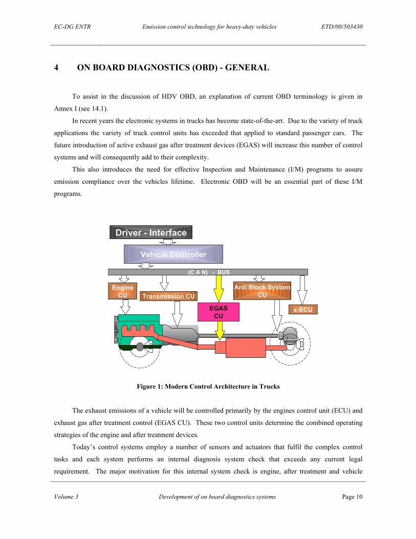
In recent years the electronic systems in trucks has become state-of-the-art. Due to the variety of truck
applications the variety of truck control units has exceeded that applied to standard passenger cars. The
future introduction of active exhaust gas after treatment devices (EGAS) will increase this number of control
systems and will consequently add to their complexity.
This also introduces the need for effective Inspection and Maintenance (I/M) programs to assure
emission compliance over the vehicles lifetime. Electronic OBD will be an essential part of these I/M
programs.
Driver - Interface
Vehicle Controller
EngineCU
(C A N) - BUS
EGASCU
Transmission CUAnti Block System
CU
x-ECU
Figure 1: Modern Control Architecture in Trucks
The exhaust emissions of a vehicle will be controlled primarily by the engines control unit (ECU) and
exhaust gas after treatment control (EGAS CU). These two control units determine the combined operating
strategies of the engine and after treatment devices.
Today’s control systems employ a number of sensors and actuators that fulfil the complex control
tasks and each system performs an internal diagnosis system check that exceeds any current legal
requirement. The major motivation for this internal system check is engine, after treatment and vehicle
EC-DG ENTR Emission control technology for heavy-duty vehicles ETD/00/503430
Volume 3 Development of on board diagnostics systems Page 11
protection. The results of these internal checks could be transferred to the OBD system. If this is not
sufficient the OBD system could use separate sensors and software to detect emission failures. Wherever
appropriate sensor technology is not available, e.g. particulate sensor, emission device models could be
introduced to calculate and predict device performance.
The planned mandatory introduction of a common OBD on trucks requires the installation of a new
electronic system with functions that are designed to detect failures in the engine and exhaust after treatment
system.
The OBD system must indicate the failure of an emission control component or system when that
failure results in an increase in emissions above pre-described thresholds and when there has been a major
functional failure of the control system.
OBD systems currently installed in passenger cars consist of:
• Emission control system - ECS could be located inside the vehicle controller or within the ECU or
stand-alone.
• Specific sensors additional to those required for operation.
• Malfunction Indicator / Malfunction Indicator Light (MI / MIL).
• Standardised diagnostic data link connector.
Within the ECS, the engine and after treatment conditions are stored as an event when an emission
related fault is detected. Consequently, vehicle operational restrictions might be triggered such as reduced
speeds and torque from the engine. These are called limp home functions.
The malfunction indicator (MI) is a visual, or audible indicator that clearly informs the driver that a
vehicle non-compliance event or malfunction of an emissions related component connected to the OBD
system has occurred. The MIL actuation is strictly regulated and is subject to location and illumination
conventions.
The diagnostic link connector is normally standardised by a service organisation; however, a standard
convention would be desirable.
EC-DG ENTR Emission control technology for heavy-duty vehicles ETD/00/503430
Volume 3 Development of on board diagnostics systems Page 12
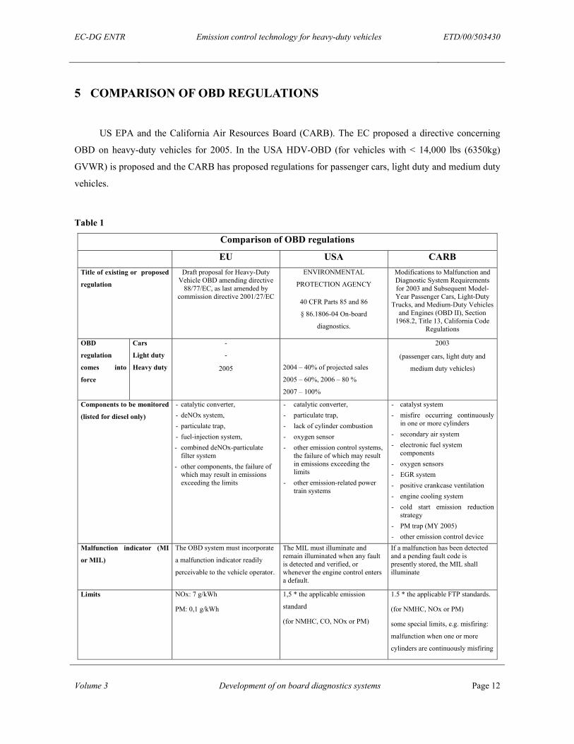
5 COMPARISON OF OBD REGULATIONS
US EPA and the California Air Resources Board (CARB). The EC proposed a directive concerning
OBD on heavy-duty vehicles for 2005. In the USA HDV-OBD (for vehicles with < 14,000 lbs (6350kg)
GVWR) is proposed and the CARB has proposed regulations for passenger cars, light duty and medium duty
vehicles.
Table 1
Comparison of OBD regulations
EU USA CARB Title of existing or proposed
regulation
Draft proposal for Heavy-Duty Vehicle OBD amending directive
88/77/EC, as last amended by commission directive 2001/27/EC
ENVIRONMENTAL
PROTECTION AGENCY
40 CFR Parts 85 and 86
§ 86.1806-04 On-board
diagnostics.
Modifications to Malfunction and Diagnostic System Requirements for 2003 and Subsequent Model-Year Passenger Cars, Light-Duty
Trucks, and Medium-Duty Vehicles and Engines (OBD II), Section
1968.2, Title 13, California Code Regulations
OBD
regulation
comes into
force
Cars
Light duty
Heavy duty
-
-
2005
2004 – 40% of projected sales
2005 – 60%, 2006 – 80 %
2007 – 100%
2003
(passenger cars, light duty and
medium duty vehicles)
Components to be monitored
(listed for diesel only)
- catalytic converter, - deNOx system, - particulate trap, - fuel-injection system, - combined deNOx-particulate
filter system - other components, the failure of
which may result in emissions exceeding the limits
- catalytic converter, - particulate trap, - lack of cylinder combustion - oxygen sensor - other emission control systems,
the failure of which may result in emissions exceeding the limits
- other emission-related power train systems
- catalyst system - misfire occurring continuously
in one or more cylinders - secondary air system - electronic fuel system
components - oxygen sensors - EGR system - positive crankcase ventilation - engine cooling system - cold start emission reduction
strategy - PM trap (MY 2005) - other emission control device
Malfunction indicator (MI
or MIL)
The OBD system must incorporate
a malfunction indicator readily
perceivable to the vehicle operator.
The MIL must illuminate and remain illuminated when any fault is detected and verified, or whenever the engine control enters a default.
If a malfunction has been detected and a pending fault code is presently stored, the MIL shall illuminate
Limits NOx: 7 g/kWh
PM: 0,1 g/kWh
1,5 * the applicable emission
standard
(for NMHC, CO, NOx or PM)
1.5 * the applicable FTP standards.
(for NMHC, NOx or PM)
some special limits, e.g. misfiring:
malfunction when one or more
cylinders are continuously misfiring
EC-DG ENTR Emission control technology for heavy-duty vehicles ETD/00/503430
Volume 3 Development of on board diagnostics systems Page 13
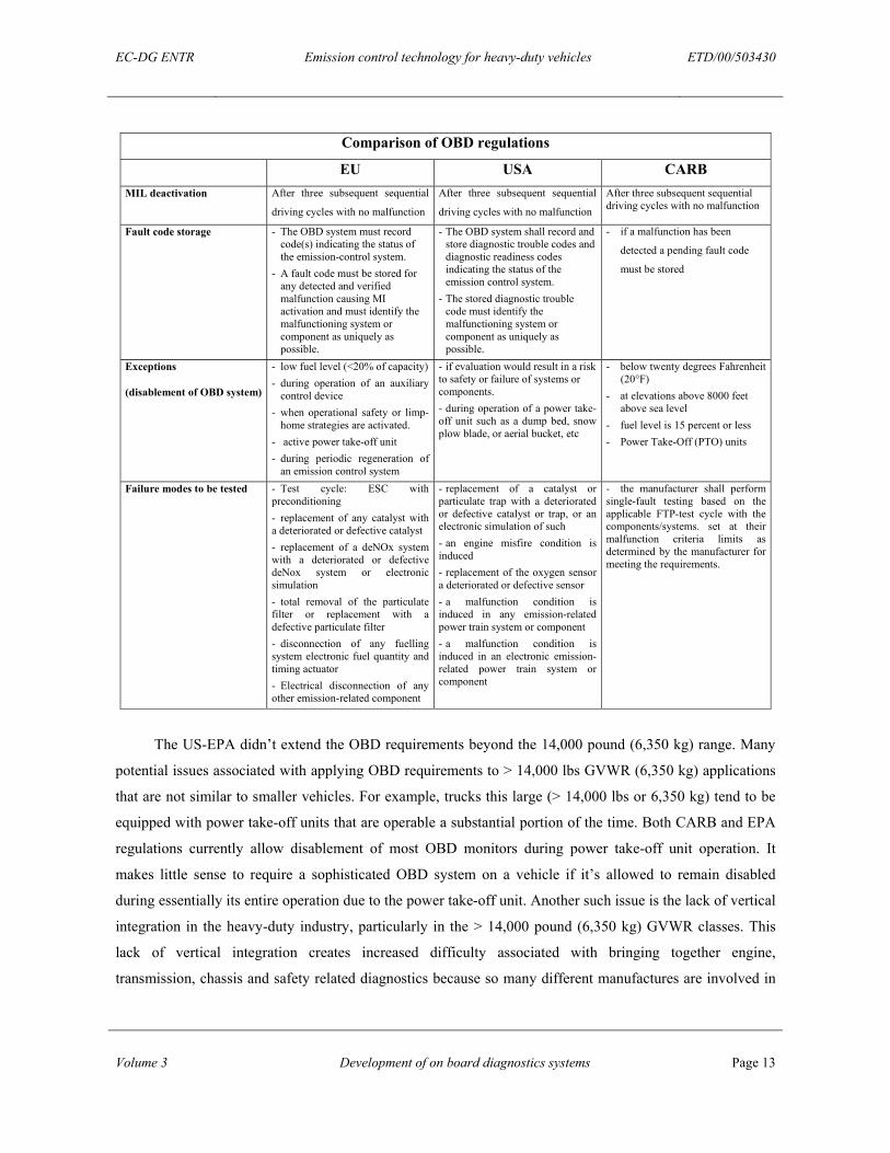
Comparison of OBD regulations
EU USA CARB MIL deactivation After three subsequent sequential
driving cycles with no malfunction
After three subsequent sequential
driving cycles with no malfunction
After three subsequent sequential driving cycles with no malfunction
Fault code storage - The OBD system must record code(s) indicating the status of the emission-control system.
- A fault code must be stored for any detected and verified malfunction causing MI activation and must identify the malfunctioning system or component as uniquely as possible.
- The OBD system shall record and store diagnostic trouble codes and diagnostic readiness codes indicating the status of the emission control system.
- The stored diagnostic trouble code must identify the malfunctioning system or component as uniquely as possible.
- if a malfunction has been
detected a pending fault code
must be stored
Exceptions
(disablement of OBD system)
- low fuel level (<20% of capacity) - during operation of an auxiliary
control device - when operational safety or limp-
home strategies are activated. - active power take-off unit - during periodic regeneration of
an emission control system
- if evaluation would result in a risk to safety or failure of systems or components. - during operation of a power take-off unit such as a dump bed, snow plow blade, or aerial bucket, etc
- below twenty degrees Fahrenheit (20°F)
- at elevations above 8000 feet above sea level
- fuel level is 15 percent or less - Power Take-Off (PTO) units
Failure modes to be tested - Test cycle: ESC with preconditioning - replacement of any catalyst with a deteriorated or defective catalyst - replacement of a deNOx system with a deteriorated or defective deNox system or electronic simulation - total removal of the particulate filter or replacement with a defective particulate filter - disconnection of any fuelling system electronic fuel quantity and timing actuator - Electrical disconnection of any other emission-related component
- replacement of a catalyst or particulate trap with a deteriorated or defective catalyst or trap, or an electronic simulation of such - an engine misfire condition is induced - replacement of the oxygen sensor a deteriorated or defective sensor - a malfunction condition is induced in any emission-related power train system or component - a malfunction condition is induced in an electronic emission-related power train system or component
- the manufacturer shall perform single-fault testing based on the applicable FTP-test cycle with the components/systems. set at their malfunction criteria limits as determined by the manufacturer for meeting the requirements.
The US-EPA didn’t extend the OBD requirements beyond the 14,000 pound (6,350 kg) range. Many
potential issues associated with applying OBD requirements to > 14,000 lbs GVWR (6,350 kg) applications
that are not similar to smaller vehicles. For example, trucks this large (> 14,000 lbs or 6,350 kg) tend to be
equipped with power take-off units that are operable a substantial portion of the time. Both CARB and EPA
regulations currently allow disablement of most OBD monitors during power take-off unit operation. It
makes little sense to require a sophisticated OBD system on a vehicle if it’s allowed to remain disabled
during essentially its entire operation due to the power take-off unit. Another such issue is the lack of vertical
integration in the heavy-duty industry, particularly in the > 14,000 pound (6,350 kg) GVWR classes. This
lack of vertical integration creates increased difficulty associated with bringing together engine,
transmission, chassis and safety related diagnostics because so many different manufactures are involved in
EC-DG ENTR Emission control technology for heavy-duty vehicles ETD/00/503430
Volume 3 Development of on board diagnostics systems Page 14
creating the end product. The EPA will gather further information and work closely with interested parties to
develop proposed OBD requirements for such engines. [1]
5.1 US FACT FINDING TOUR
As part of this study, the US EPA and American truck manufacturers were visited and asked for their
opinions on the future development of the HDV industry, emissions control strategies and the possibilities
for OBD. The information is summarised below:
In the US, vehicles in the size range 8,500 to 14,000 lbs (3,856 to 6,350 kg) can be vehicle or engine
certified. CARB requires these vehicles to have OBD and the EPA is introducing similar Federal
requirements. It was thought that OBD would be incorporated into the 2007 heavy-duty diesel engine
regulations. However, this did not occur. The EPA is looking closely at the EU experience before
progressing with this and is keen to co-operate with the European Commission on this issue.
Caterpillar argues that because the profit margins for their product are small, the introduction of OBD
would be too costly and consequently OBD requirement for Euro IV might drive the company out of the
market. Cummins and Detroit Diesel Corporation (DDC) recognise that OBD is likely to happen in the US,
but is currently in its infancy.
In the US and EU, different communication protocols are used. Also within the US, light and heavy-
duty engines use different protocols. Cummins would like to standardise on the US HD communication
protocols in the EU (see chapter 9).
It is likely that NOx sensors will be required for DeNOx devices. However, it is unlikely that PM
sensors that have been proved to be very durable will be required for oxidation catalysts. For DPF it may be
considered sufficient to monitor for major malfunction rather than monitor PM directly.
Any future on-board monitoring (OBM) i.e. the in-vehicle measurement of exhaust emissions using
dedicated sensors will also require OBD which will enable the driver to know that there has been a pollution
episode and the reason why.
Currently there are no Inspection and Maintenance (I/M), requirements for heavy-duty vehicles in the
US. The EPA envisages that once ODB is implemented in HDTV’s, this might lead the way to I/M.
EC-DG ENTR Emission control technology for heavy-duty vehicles ETD/00/503430
Volume 3 Development of on board diagnostics systems Page 15
6 OVERVIEW ON OBD REQUIREMENTS
The OBD system must indicate the failure of an emission control component or system when that
failure results in increased emissions above set thresholds and on the occurrence of a major functional
failure.
To detect malfunctions relevant to the emissions behaviour of the vehicle, two different approaches
can be taken into consideration:
• Direct measurement of the emissions at the tailpipe
• Indirect method by monitoring parameters that would change as a result of a malfunction. For
example, pressures, temperatures and engine speed. This data would be inputted into to an advanced
model for calculating the emission behaviour.
The first approach would require accurate and reliable sensors for NOx, CO, HC and PM that are not
currently available for in service monitoring and are also expected to be expensive. Furthermore, sensor
calibration and the ageing of the sensor over time can have a significant effect on the accuracy of this
method. Consequently, OBD in passenger cars is based on the latter method and is believed to be the short-
term.
This method would require reliable, simple sensors on one hand and a sophisticated strategy to check
the signals against complex models on the other hand. The model software needs to be implemented in the
OBD controller or subsystem controller.
In case of using the direct method of analysing tail pipe emissions and reporting that the emissions
have exceeded the pre-described limit, there is little opportunity to isolate the reason for the non-compliance.
The indirect method provides a better chance to detect the reason and location of the fault and therefore
provides valuable maintenance information at the same time.
In practice it is most likely that the OBD systems will utilise a combination of the direct and indirect
method.
The definition of parameters to be measured and how the signals are processed is usually driven by the
operational requirements of the respective system. In some cases the use of dedicated additional OBD
sensors will be necessary and the additional sensor inputs need to be implemented into the respective control
system or into the supervisory OBD control unit.
EC-DG ENTR Emission control technology for heavy-duty vehicles ETD/00/503430
Volume 3 Development of on board diagnostics systems Page 16
7 EMISSION CONTROL SYSTEMS
Emission control systems need to be defined, the possible malfunctions and failures described and the
effect of their failure on emissions quantified. Also the sensors that could be used for OBD are described.
The following emission control systems will be considered:
• Diesel Particulate Filters (DPF)
• NOx adsorbers
• Fuel supply and Injection systems
• Exhaust Gas Recirculation (EGR) systems
• Selective Catalytic Reduction
The working principles of these exhaust emission control systems are described in greater detail in
Volume1 “Survey of Future Emission Control Techniques”.
Obviously, the first sequence in any OBD system is the identification of the unit being monitored and
that the unit is installed correctly. For example, has the particulate filter been removed? Secondly, an
interrogation of the electrical integrity of the sensor circuits would be required.
7.1 DIESEL PARTICULATE FILTER (DPF)
There are different systems to reduce particulate matter (PM) emissions.
• Continuously Regenerating Trap (CRT, Johnson Matthey)
• Fuel-Born Catalysed Filter
• Fuel Burner Regenerating Trap
• Catalysed Diesel Particulate Filter (CDPF, “CSF“ catalysed soot filter)
EC-DG ENTR Emission control technology for heavy-duty vehicles ETD/00/503430
Volume 3 Development of on board diagnostics systems Page 17
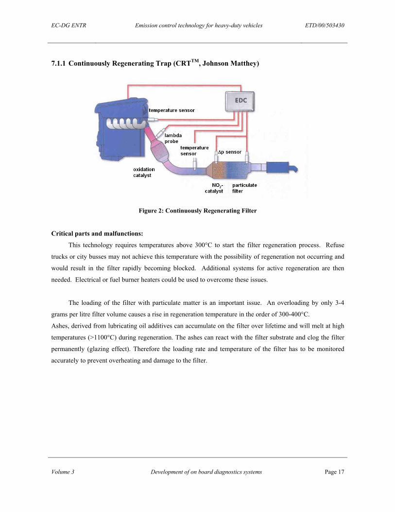
7.1.1 Continuously Regenerating Trap (CRTTM, Johnson Matthey)
Figure 2: Continuously Regenerating Filter
Critical parts and malfunctions:
This technology requires temperatures above 300°C to start the filter regeneration process. Refuse
trucks or city busses may not achieve this temperature with the possibility of regeneration not occurring and
would result in the filter rapidly becoming blocked. Additional systems for active regeneration are then
needed. Electrical or fuel burner heaters could be used to overcome these issues.
The loading of the filter with particulate matter is an important issue. An overloading by only 3-4
grams per litre filter volume causes a rise in regeneration temperature in the order of 300-400°C.
Ashes, derived from lubricating oil additives can accumulate on the filter over lifetime and will melt at high
temperatures (>1100°C) during regeneration. The ashes can react with the filter substrate and clog the filter
permanently (glazing effect). Therefore the loading rate and temperature of the filter has to be monitored
accurately to prevent overheating and damage to the filter.
EC-DG ENTR Emission control technology for heavy-duty vehicles ETD/00/503430
Volume 3 Development of on board diagnostics systems Page 18
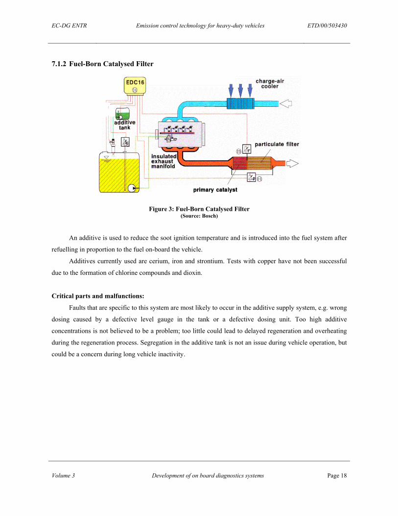
7.1.2 Fuel-Born Catalysed Filter
Figure 3: Fuel-Born Catalysed Filter (Source: Bosch)
An additive is used to reduce the soot ignition temperature and is introduced into the fuel system after
refuelling in proportion to the fuel on-board the vehicle.
Additives currently used are cerium, iron and strontium. Tests with copper have not been successful
due to the formation of chlorine compounds and dioxin.
Critical parts and malfunctions:
Faults that are specific to this system are most likely to occur in the additive supply system, e.g. wrong
dosing caused by a defective level gauge in the tank or a defective dosing unit. Too high additive
concentrations is not believed to be a problem; too little could lead to delayed regeneration and overheating
during the regeneration process. Segregation in the additive tank is not an issue during vehicle operation, but
could be a concern during long vehicle inactivity.
EC-DG ENTR Emission control technology for heavy-duty vehicles ETD/00/503430
Volume 3 Development of on board diagnostics systems Page 19
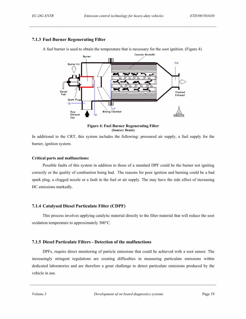
7.1.3 Fuel Burner Regenerating Filter
A fuel burner is used to obtain the temperature that is necessary for the soot ignition. (Figure 4)
Figure 4: Fuel Burner Regenerating Filter (Source: Deutz)
In additional to the CRT, this system includes the following: pressured air supply, a fuel supply for the
burner, ignition system.
Critical parts and malfunctions:
Possible faults of this system in addition to those of a standard DPF could be the burner not igniting
correctly or the quality of combustion being bad. The reasons for poor ignition and burning could be a bad
spark plug, a clogged nozzle or a fault in the fuel or air supply. The may have the side effect of increasing
HC emissions markedly.
7.1.4 Catalysed Diesel Particulate Filter (CDPF)
This process involves applying catalytic material directly to the filter material that will reduce the soot
oxidation temperature to approximately 300°C.
7.1.5 Diesel Particulate Filters - Detection of the malfunctions
DPFs, require direct monitoring of particle emissions that could be achieved with a soot sensor. The
increasingly stringent regulations are creating difficulties in measuring particulate emissions within
dedicated laboratories and are therefore a great challenge to detect particulate emissions produced by the
vehicle in use.
EC-DG ENTR Emission control technology for heavy-duty vehicles ETD/00/503430
Volume 3 Development of on board diagnostics systems Page 20
There have been attempts to develop a soot sensor, but these are not yet commercially available for
vehicles. It is considered unlikely that they will be available in the 2005 timescale. [1] [2] [3]
Indirect monitoring can be achieved by measuring the drop in pressure across the filter. The drop in
pressure between the input and the output of the filter is used to assess the quantity of soot in the particulate
filter. However, this pressure difference fluctuates with engine speed and load conditions. Pressure sensors
are also sensitive to soot fouling and gas condensation. [3]
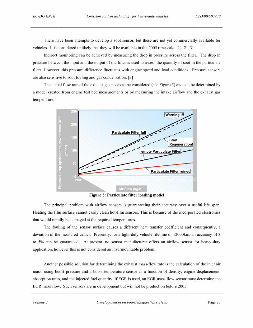
The actual flow rate of the exhaust gas needs to be considered (see Figure 5) and can be determined by
a model created from engine test bed measurements or by measuring the intake airflow and the exhaust gas
temperature.
0
50
100
150
200
250
200 300 400 500 600 700 800 900 1000 1100 1200
Air Mass (kg/h)
Exh
aust
Bac
kpre
ssur
e(m
bar)
empty Particulate Filter
Particulate Filter ruined
Warning !!!
Start Regeneration!
Particulate Filter full
Pres
sure
dro
p up
stre
am to
dow
nstr
eam
DPF
[mba
r)
Air Flow (kg/h) Figure 5: Particulate filter loading model
The principal problem with airflow sensors is guaranteeing their accuracy over a useful life span.
Heating the film surface cannot easily clean hot-film sensors. This is because of the incorporated electronics
that would rapidly be damaged at the required temperatures.
The fouling of the sensor surface causes a different heat transfer coefficient and consequently, a
deviation of the measured values. Presently, for a light-duty vehicle lifetime of 12000km, an accuracy of 3
to 5% can be guaranteed. At present, no sensor manufacturer offers an airflow sensor for heavy-duty
application, however this is not considered an insurmountable problem.
Another possible solution for determining the exhaust mass-flow rate is the calculation of the inlet air
mass, using boost pressure and a boost temperature sensor as a function of density, engine displacement,
absorption ratio, and the injected fuel quantity. If EGR is used, an EGR mass flow sensor must determine the
EGR mass flow. Such sensors are in development but will not be production before 2005.
EC-DG ENTR Emission control technology for heavy-duty vehicles ETD/00/503430
Volume 3 Development of on board diagnostics systems Page 21
To monitor the correct functioning of the oxidation catalyst and to protect the filter against
overheating, an additional three temperature sensors would be required to detect an increase in temperature
over the catalyst, a sensor should be mounted upstream and downstream of the oxidation catalyst. The third
is placed downstream of the particulate filter to detect excessive temperatures resulting from the
regeneration.
Additional requirements for fuel born catalysed filter:
Filters that require a fuel born catalyst have to have the correct catalyst-dosing regime monitored.
Initially, the level in the tank is monitored by the fluid level indicator and will give a warning signal at a
defined low level. The direct method to monitor the correct dosing of the additive could be to measure the
concentration of the additive in the fuel. Measuring the electrical conductivity of the fluid could achieve this
but there are no suitable sensors identified at this time.
An easy, but not accurate method to monitor the correct fuel dosing is to check the additive
consumption and compare it with a known consumption figure for the driven kilometres.
An important point is the use of the right regulated additive and how to detect non-compliance. The use of
unregulated additives, such as those that contain cooper, can extend the regeneration period and
consequently reduce fuel consumption. To prevent this misuse, the sensor system would detect all
unregulated additives, but at this time there are no sensors known which are capable of achieving this.
Additional requirements for DPF with fuel burner:
The correct function of a fuel burner DPF is dependant on the correct ignition and burning of the fuel.
Faults can be caused by a clogged nozzle or incorrect air supply. The easiest way to monitor the ignition and
combustion would be the use of a temperature sensor sited in the burner. A second but more complex and
expensive method is the use of an optical sensor that detects the light of the burner combined with CO
sensors, which are currently not available.
EC-DG ENTR Emission control technology for heavy-duty vehicles ETD/00/503430
Volume 3 Development of on board diagnostics systems Page 22
7.2 NOX ADSORBERS
There are two known after treatment systems to reduce NOx emissions.
• Selective Catalytic Reduction (SCR)
• DeNOx (Lean NOx) Catalyst
7.2.1 Selective Catalytic Reduction (SCR)
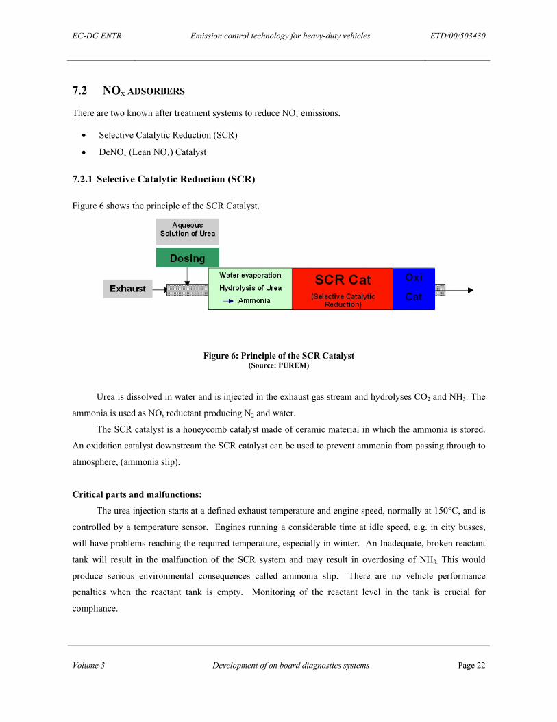
Figure 6 shows the principle of the SCR Catalyst.
Figure 6: Principle of the SCR Catalyst (Source: PUREM)
Urea is dissolved in water and is injected in the exhaust gas stream and hydrolyses CO2 and NH3. The
ammonia is used as NOx reductant producing N2 and water.
The SCR catalyst is a honeycomb catalyst made of ceramic material in which the ammonia is stored.
An oxidation catalyst downstream the SCR catalyst can be used to prevent ammonia from passing through to
atmosphere, (ammonia slip).
Critical parts and malfunctions:
The urea injection starts at a defined exhaust temperature and engine speed, normally at 150°C, and is
controlled by a temperature sensor. Engines running a considerable time at idle speed, e.g. in city busses,
will have problems reaching the required temperature, especially in winter. An Inadequate, broken reactant
tank will result in the malfunction of the SCR system and may result in overdosing of NH3. This would
produce serious environmental consequences called ammonia slip. There are no vehicle performance
penalties when the reactant tank is empty. Monitoring of the reactant level in the tank is crucial for
compliance.
EC-DG ENTR Emission control technology for heavy-duty vehicles ETD/00/503430
Volume 3 Development of on board diagnostics systems Page 23
7.2.2 DeNOx (Lean NOx) Catalyst
The DeNOx catalyst stores NOx as nitrate during lean operation and releases the NOx under rich
conditions where the NO2 is reduced by the hydrocarbons.
For heavy duty-vehicles applications a large catalyst volume is needed which could be several times
the cylinder capacity and therefore this system is unlikely to be used.
Critical parts and malfunctions:
This system is extremely sensitive to sulphur, even when using low-sulphur fuels. This requires the
catalyst to be cleaned of sulphur every 10–15 hours of operation. This is achieved by raising the catalyst
temperature to over 600oC by introducing fuel to the catalyst directly via injection into the exhaust or the
engine. However, these high temperatures, especially under oxidizing conditions can cause the catalytic
material to melt and recrystallise randomly across the catalysts ceramic monolith, permanently decreasing
the NOx adsorber performance.
Proper NOx adsorber function requires extensive functionalities implemented in the ECU using both
NOx adsorber and a raw emission models. These models can be built from physical data or models based on
simple emission maps. The models and the controllers require a NOx sensor to determine NOx breakthrough
and the state of ageing and sulphur poisoning of the adsorber. These models can also be incorporated into
OBD functions
7.2.3 NOx adsorbers - Detection of the malfunctions
The most effective method to monitor the effectiveness of the NOx adsorber is to monitor the levels of
NOx. A NOx sensor downstream from the SCR-catalyst used for closed-loop NOx control could be used
together with a NOx sensor upstream of the SCR-catalyst. The rate of NOx conversion could then be
calculated and the condition of the catalyst assessed.
NOx sensors are available for passenger cars but are still considered expensive. However, there is a
major difficulty in implementing the malfunction strategy described above using current NOx sensor
technology, namely, they respond to ammonia as well as to NOx which is clearly undesirable in a system in
which both ammonia and NOx will be present. Further developments in sensor technology and system
integration are likely to be required before an effective NOx monitoring system is available. [2]
The cross sensitivity of the NOx sensor to NH3 mentioned above is another point at the SCR system.
The NOx sensor downstream the SCR would detect the NOx reduction but also a possible NH3 breakthrough.
A high level at this sensor would show that there is a fault in the system but not if there is too much NOx or
EC-DG ENTR Emission control technology for heavy-duty vehicles ETD/00/503430
Volume 3 Development of on board diagnostics systems Page 24
undesirable NH3 emissions. Many tests would be necessary to define signal levels for every possible fault of
the SCR system or the NH3 dosing.
US truck manufacturers believe that the NOx sensor technique for direct NOx measurement of
reduction catalysts will not be in production by the 2004 model year and these sensors are expected to be
very expensive. [1]
To detect incorrect NH3 dosing and reactant tank level, a sensor together with a basic model and
distance driven could be used. This however, this is not considered sufficiently accurate.
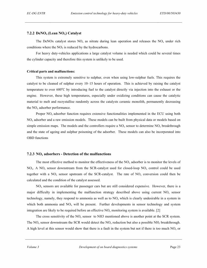
7.3 LOW PRESSURE FUEL SYSTEM
The task of the low-pressure fuel system is to store the fuel and guarantee the correct fuel supply to the
injection systems.
Figure 7: Low pressure circuit of a CR injection system (Source: Bosch)
Possible faults in the fuelling system:
• Breakdown of the fuel pump
• Leakage in the tank or tubing
• Fault of the level sensor
• A clogged fuel filter
EC-DG ENTR Emission control technology for heavy-duty vehicles ETD/00/503430
Volume 3 Development of on board diagnostics systems Page 25
7.4 INJECTION SYSTEMS
The following injection systems are commonly used in HDV engines.
• Distributor Injection Pump
• Electronic Unit Injector (EUI) + Electronic Unit Pump (EUP)
• Common Rail
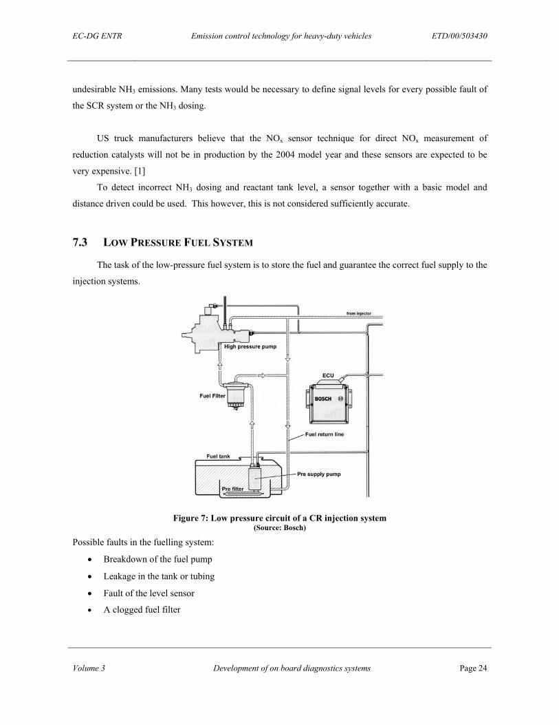
7.4.1 Distributor Injection Pump
The subsystems of the distributor injection pump system that could have an effect upon the vehicles
emissions are, the pump, line, nozzle, sensors and electronics. In Table 2 critical parts and possible
malfunctions of these subsystems are described and the influence on emissions is assessed.
Table 2
Critical Parts and Malfunctions of the Distributor Injection Pump
Influence on emissions
Defective injection timing device + + + Wear/dirt or leaking electromagnetic valve => increased leakage + + + Pump Defective pre-supply pump/leaking housing/leaking pressure holding valve + + +
Leaking screw => lower pressure, less injection rate + Line Crack in the line => total break of the line => engine breakdown 0 Defective needle-travel sensor => wrong timing + + + Bursting of the nozzle + + + Coking of the nozzle + Seizing of the needle (open) => engine break down 0 Spring breakage => engine break down 0 Leakage in nozzle holder +
Nozzle
Seat wear and seat fouling + Engine-camshaft rotational speed => inexact start of injection ++ Defective air flow sensor + + + Cooling water temperature sensor (e.g. False cold start)* ++
Electronics Sensors
Fuel temperature sensor + 0 …… no influence on emissions +++ … high influence on emissions
*‘False cold-start’ means that the cooling temperature sensor suggests a temperature that would stimulate the engine control to initiate cold start conditions. (e.g. different injection timing to reach operating temperature faster)
EC-DG ENTR Emission control technology for heavy-duty vehicles ETD/00/503430
Volume 3 Development of on board diagnostics systems Page 26
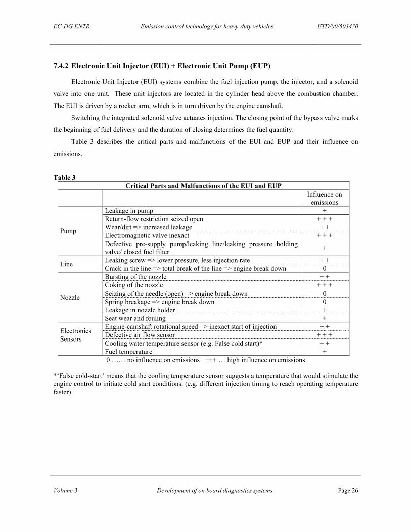
7.4.2 Electronic Unit Injector (EUI) + Electronic Unit Pump (EUP)
Electronic Unit Injector (EUI) systems combine the fuel injection pump, the injector, and a solenoid
valve into one unit. These unit injectors are located in the cylinder head above the combustion chamber.
The EUI is driven by a rocker arm, which is in turn driven by the engine camshaft.
Switching the integrated solenoid valve actuates injection. The closing point of the bypass valve marks
the beginning of fuel delivery and the duration of closing determines the fuel quantity.
Table 3 describes the critical parts and malfunctions of the EUI and EUP and their influence on
emissions.
Table 3 Critical Parts and Malfunctions of the EUI and EUP
Influence on emissions
Leakage in pump + Return-flow restriction seized open + + + Wear/dirt => increased leakage + + Electromagnetic valve inexact + + + Pump
Defective pre-supply pump/leaking line/leaking pressure holding valve/ closed fuel filter +
Leaking screw => lower pressure, less injection rate + + Line Crack in the line => total break of the line => engine break down 0 Bursting of the nozzle + + Coking of the nozzle + + + Seizing of the needle (open) => engine break down 0 Spring breakage => engine break down 0 Leakage in nozzle holder +
Nozzle
Seat wear and fouling + Engine-camshaft rotational speed => inexact start of injection + + Defective air flow sensor + + + Cooling water temperature sensor (e.g. False cold start)* + +
Electronics Sensors
Fuel temperature + 0 …… no influence on emissions +++ … high influence on emissions
*‘False cold-start’ means that the cooling temperature sensor suggests a temperature that would stimulate the engine control to initiate cold start conditions. (e.g. different injection timing to reach operating temperature faster)
EC-DG ENTR Emission control technology for heavy-duty vehicles ETD/00/503430
Volume 3 Development of on board diagnostics systems Page 27
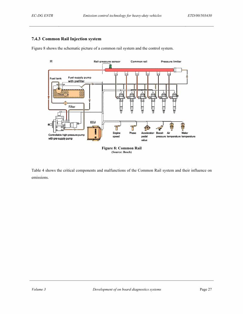
7.4.3 Common Rail Injection system
Figure 8 shows the schematic picture of a common rail system and the control system.
Figure 8: Common Rail (Source: Bosch)
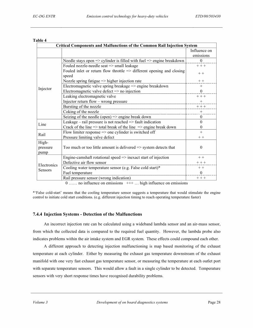
Table 4 shows the critical components and malfunctions of the Common Rail system and their influence on
emissions.
EC-DG ENTR Emission control technology for heavy-duty vehicles ETD/00/503430
Volume 3 Development of on board diagnostics systems Page 28
Table 4 Critical Components and Malfunctions of the Common Rail Injection System
Influence on emissions
Needle stays open => cylinder is filled with fuel => engine breakdown 0 Fouled nozzle-needle seat => small leakage + + + Fouled inlet or return flow throttle => different opening and closing speed + +
Nozzle spring fatigue => higher injection rate + + Electromagnetic valve spring breakage => engine breakdown + Electromagnetic valve defect => no injection 0 Leaking electromagnetic valve + + + Injector return flow – wrong pressure + Bursting of the nozzle + + + Coking of the nozzle +
Injector
Seizing of the needle (open) => engine break down 0 Leakage – rail pressure is not reached => fault indication 0 Line Crack of the line => total break of the line => engine break down 0 Flow limiter response => one cylinder is switched off + Rail Pressure limiting valve defect + +
High-pressure pump
Too much or too little amount is delivered => system detects that 0
Engine-camshaft rotational speed => inexact start of injection + + Defective air flow sensor + + + Cooling water temperature sensor (e.g. False cold start)* + + Fuel temperature 0
Electronics Sensors
Rail pressure sensor (wrong indication) + + + 0 …… no influence on emissions +++ … high influence on emissions
*‘False cold-start’ means that the cooling temperature sensor suggests a temperature that would stimulate the engine control to initiate cold start conditions. (e.g. different injection timing to reach operating temperature faster)
7.4.4 Injection Systems - Detection of the Malfunctions
An incorrect injection rate can be calculated using a wideband lambda sensor and an air-mass sensor,
from which the collected data is compared to the required fuel quantity. However, the lambda probe also
indicates problems within the air intake system and EGR system. These effects could compound each other.
A different approach to detecting injection malfunctioning is map based monitoring of the exhaust
temperature at each cylinder. Either by measuring the exhaust gas temperature downstream of the exhaust
manifold with one very fast exhaust gas temperature sensor, or measuring the temperature at each outlet port
with separate temperature sensors. This would allow a fault in a single cylinder to be detected. Temperature
sensors with very short response times have recognised durability problems.
EC-DG ENTR Emission control technology for heavy-duty vehicles ETD/00/503430
Volume 3 Development of on board diagnostics systems Page 29
Another approach is analysing the angular accelerations of the flywheel. If there were a fault of the
injection system in one cylinder, variations of engine accelerations would occur. This technique would work
well at idle and at low engine speeds but would have problems at higher engine speeds.
The varying start of injection caused by a change in injection pressure or wear of the nozzle is
monitored by a control loop with a needle travel sensor.
7.5 EXHAUST GAS RECIRCULATION (EGR)
EGR is used to reduce NOx emissions by recirculating a proportion of the exhaust gas back into the
combustion cylinder. This reduces the oxygen available in the cylinder for combustion and creates lower
peak temperatures that inhibit the formation NOx.
There are different principles of exhaust gas recirculation.
• External High Pressure EGR
• External Low Pressure EGR
• Internal EGR
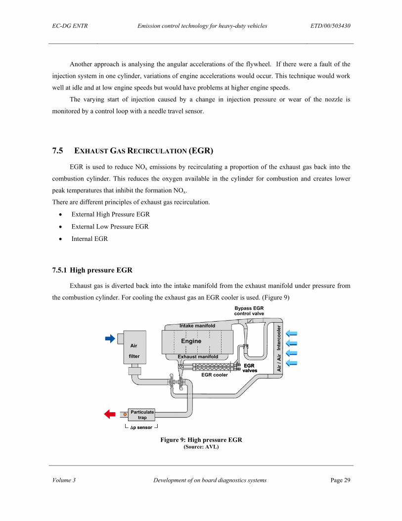
7.5.1 High pressure EGR
Exhaust gas is diverted back into the intake manifold from the exhaust manifold under pressure from
the combustion cylinder. For cooling the exhaust gas an EGR cooler is used. (Figure 9)
EGR coolers
Bypass EGRcontrol valve
Intake manifold
Exhaust manifold
Engine
EGR on/offvalves
CRTTM
Airfilter
Air flowmeter
Air /
Air
Inte
rcoo
ler
Vent
uri
∆∆p p sensor sensor ∆∆p p sensor sensor
EGR cooler
EGRvalvesEGRvalves
Air
filter
Intake manifold
Air /
Air
Inte
rcoo
ler
Engine
Exhaust manifold
Particulatetrap
Figure 9: High pressure EGR
(Source: AVL)
EC-DG ENTR Emission control technology for heavy-duty vehicles ETD/00/503430
Volume 3 Development of on board diagnostics systems Page 30
7.5.2 Low pressure EGR
The low pressure EGR re-routes the exhaust gas from after the turbocharger and particulate filter to
the fresh airflow before the turbocharger. (Figure 10)
EGR cooler
EGRvalve
Air filter
Intake manifold
Air /
Air
Inte
rcoo
ler
Engine
Exhaust manifold
Particulatetrap
NOxNOx sensorsensor∆∆p p sensor sensor
Figure 10: Low pressure EGR
(Source: AVL)
7.5.3 Internal EGR
An overlapping opening of the exhaust and the intake valve results in a mixture of fresh air and
exhaust gas in the cylinder. (Figure 11)
Turbo-Charger
ExhaustAir
Intercooler
Cam Shaft
AdditionalCam Lobe on Exh. Camfor EGR-Lift
Exh.ValveInt.
Valve
Piston
EGR
201030-04
Turbo-Charger
ExhaustAir
Intercooler
Cam Shaft
AdditionalCam Lobe on Exh. Camfor EGR-Lift
Exh.ValveInt.
Valve
Piston
EGR
201030-04
90 180 270 360 450 540 630
Valv
eLi
ft
Scavenging TDC
Valve lift Curves for internal EGR
Intake Valve
Exh.Valve
Exh. ValveEGR-Lift
Figure 11: Internal EGR) (Source: Hino Motors Limited
EC-DG ENTR Emission control technology for heavy-duty vehicles ETD/00/503430
Volume 3 Development of on board diagnostics systems Page 31
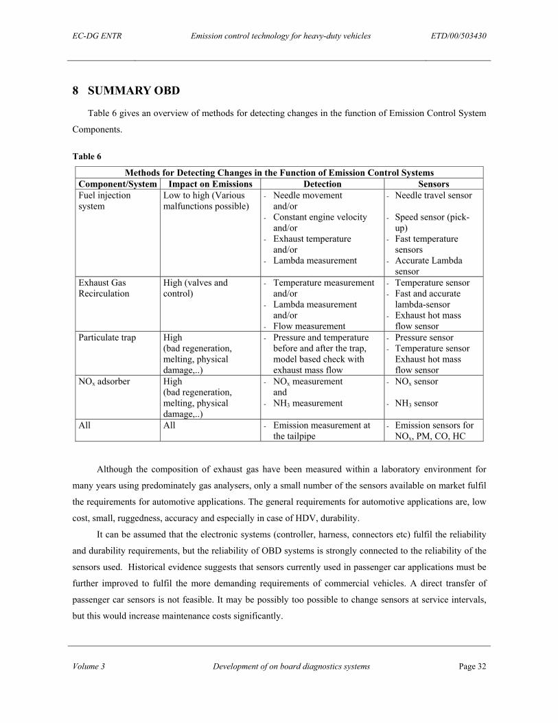
7.5.4 Exhaust Gas Recirculation - Possible Malfunctions and their detection
Table 5
EGR- Possible faults and their influence on emissions Seized EGR valve +++ Defective intake manifold throttle +++ Leaking EGR cooler (water injection) + Leaking EGR-line ++ Defective fresh air flow sensor (= control variable) ++
+ …… low influence on emissions +++ … high influence on emissions
Direct emission measurement:
The rate of EGR has a big influence on NOx emissions. Therefore, a NOx sensor within the exhaust
will detect faults in the EGR system comparing the measured values with engine map based models.
Indirect methods:
Temperature sensors are too slow for dynamic conditions, but could be used to detect a sticking EGR
valve. A valve that has become permanently closed could be detected by mounting a temperature sensor
directly within the EGR system. By locating the sensor in the intake system (after the EGR connection), a
valve that has become permanently open could be detected through observing rising temperatures in the
intake system. A more logical solution to identify stuck valves would be to incorporate a position transducer
into the valve itself. Few actuators can offer this facility
Most vehicle control systems shut off EGR in the case of a malfunction to protect the engine. A
temperature sensor could also be used to detect faults in the EGR cooler, again by comparison with a map-
based model.
The EGR mass flow could be monitored with a flow sensor located after the EGR cooler measuring
the pressure drop over the EGR valve.
EC-DG ENTR Emission control technology for heavy-duty vehicles ETD/00/503430
Volume 3 Development of on board diagnostics systems Page 32
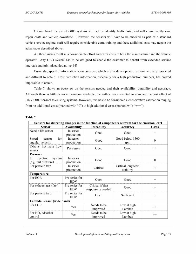
8 SUMMARY OBD
Table 6 gives an overview of methods for detecting changes in the function of Emission Control System
Components.
Table 6
Methods for Detecting Changes in the Function of Emission Control Systems Component/System Impact on Emissions Detection Sensors Fuel injection system
Low to high (Various malfunctions possible)
- Needle movement and/or - Constant engine velocity and/or - Exhaust temperature and/or - Lambda measurement
- Needle travel sensor - Speed sensor (pick-
up) - Fast temperature
sensors - Accurate Lambda
sensor Exhaust Gas Recirculation
High (valves and control)
- Temperature measurement and/or - Lambda measurement and/or - Flow measurement
- Temperature sensor - Fast and accurate
lambda-sensor - Exhaust hot mass
flow sensor Particulate trap High
(bad regeneration, melting, physical damage,..)
- Pressure and temperature before and after the trap, model based check with exhaust mass flow
- Pressure sensor - Temperature sensor
Exhaust hot mass flow sensor
NOx adsorber High (bad regeneration, melting, physical damage,..)
- NOx measurement and - NH3 measurement
- NOx sensor - NH3 sensor
All All - Emission measurement at the tailpipe
- Emission sensors for NOx, PM, CO, HC
Although the composition of exhaust gas have been measured within a laboratory environment for
many years using predominately gas analysers, only a small number of the sensors available on market fulfil
the requirements for automotive applications. The general requirements for automotive applications are, low
cost, small, ruggedness, accuracy and especially in case of HDV, durability.
It can be assumed that the electronic systems (controller, harness, connectors etc) fulfil the reliability
and durability requirements, but the reliability of OBD systems is strongly connected to the reliability of the
sensors used. Historical evidence suggests that sensors currently used in passenger car applications must be
further improved to fulfil the more demanding requirements of commercial vehicles. A direct transfer of
passenger car sensors is not feasible. It may be possibly too possible to change sensors at service intervals,
but this would increase maintenance costs significantly.
EC-DG ENTR Emission control technology for heavy-duty vehicles ETD/00/503430
Volume 3 Development of on board diagnostics systems Page 33
On one hand, the use of OBD systems will help to identify faults faster and will consequently save
repair costs and vehicle downtime. However, the sensors will have to be checked as part of a standard
vehicle service regime, staff will require considerable extra training and these additional cost may negate the
advantages described above.
All these issues result in a considerable effort and extra costs to both the manufacturer and the vehicle
operator. Any OBD system has to be designed to enable the customer to benefit from extended service
intervals and minimized downtime. [4]
Currently, specific information about sensors, which are in development, is commercially restricted
and difficult to obtain. Cost prediction information, especially for a high production numbers, has proved
impossible to obtain.
Table 7, shows an overview on the sensors needed and their availability, durability and accuracy.
Although there is little or no information available, the author has attempted to compare the cost effect of
HDV OBD sensors to existing systems. However, this has to be considered a conservative estimation ranging
from no additional costs (marked with “0”) to high additional costs (marked with “+++”).
Table 7
Sensors for detecting changes in the function of components relevant for the emission level Sensor Availability Durability Accuracy Costs
Needle lift sensor In series production Good Good +
Speed sensor for angular velocity
In series production Good Good below 1500
rpm 0
Exhaust hot mass flow sensor Pre series Open Good ++
Pressure In Injection system (e.g. rail pressure)
In series production Good Good 0
For particle trap In series production Critical Critical long term
stability ++
Temperature For EGR Pre series for
HDV Open Good +
For exhaust gas (fast) Pre series for HDV
Critical if fast response is needed Good +
For particle trap Pre series for HDV Open Sufficient +
Lambda Sensor (wide band) For EGR Yes Needs to be
improved Low at high
Lambda ++
For NOx adsorber control Yes Needs to be
improved Low at high
Lambda ++
EC-DG ENTR Emission control technology for heavy-duty vehicles ETD/00/503430
Volume 3 Development of on board diagnostics systems Page 34
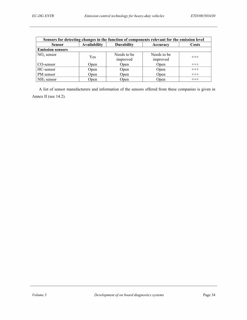
Sensors for detecting changes in the function of components relevant for the emission level Sensor Availability Durability Accuracy Costs
Emission sensors NOx sensor Yes Needs to be
improved Needs to be improved +++
CO-sensor Open Open Open +++ HC-sensor Open Open Open +++ PM sensor Open Open Open +++ NH3 sensor Open Open Open +++
A list of sensor manufacturers and information of the sensors offered from these companies is given in
Annex II (see 14.2).
EC-DG ENTR Emission control technology for heavy-duty vehicles ETD/00/503430
Volume 3 Development of on board diagnostics systems Page 35
9 FAULT STORAGE AND ENHANCED FUNCTION OF OBD
In addition to the detection of malfunctions and non-compliance to emissions limits, the OBD system
has to have the capability of storing collected information and allow interrogation enabling the fault to be
located and the reason for the fault to be identified. The following is a description of the fault storage
functions extracted from the US EPA regulation § 86.099–17.
OBD systems should be designed to be able to record and store in computer memory diagnostic
trouble codes and diagnostic readiness codes indicating the status of the emission control system. These
codes shall be available through the standardized data link connector. A diagnostic trouble code shall
identify the malfunctioning system or component as uniquely as possible and should be stored for any
detected and verified malfunction causing MIL illumination.
Separate status codes, or readiness codes, shall be stored in computer memory to identify correctly
functioning emission control systems and those emission control systems which require further vehicle
operation to complete proper diagnostic evaluation.
Upon determination of the first malfunction of any component or system, ‘‘freeze frame’’ engine
conditions present at the time shall be stored in computer memory. Stored engine conditions shall include,
but are not limited to: engine speed, open or closed loop operation, fuel system commands, coolant
temperature, calculated load value, fuel pressure, vehicle speed, air flow rate, and intake manifold pressure if
the information needed to determine these conditions is available to the computer. For freeze frame storage,
the manufacturer shall include the most appropriate set of conditions to facilitate effective repairs.
Access to the data required shall be available through a standardized data link connector and shall be
unrestricted and not require any access codes or devices that are only available from the manufacturer (OBD
standardisation).
OBD Standardisation
Generally the aim of OBD standardisation is to allow independent or "free" vehicle service agents
unrestricted access to the stored OBD data. Therefore the connection interface between the vehicle system
and the diagnostic tool must be standardised and meet all the requirements of ISO 15031-3 (Road vehicles -
Communication between vehicle and external test equipment for emission-related diagnostics).
ISO 15031 rules out the possibility of communication between vehicle systems and diagnostic tools.
Four ways are currently available:
• Serial link using vehicle voltage level according ISO 9141-2
• Keyword 2000 protocol according ISO 14230
• SAE J1850 (already obsolete)
• CAN Bus according ISO DIS 15765-4 (not yet in use, but currently prepared)
EC-DG ENTR Emission control technology for heavy-duty vehicles ETD/00/503430
Volume 3 Development of on board diagnostics systems Page 36
In Europe, a working group exist engaged in preparing a new ISO regulation (ISO 15765). European
truck manufacturers prefer ISO 15765 and it is expected that this will be adopted by all EU member states.
ISO 15031 includes the technical specifications and solutions that are required by CARB, EPA, and
EU and for future inclusion by Japan. For passenger cars and heavy-duty vehicles, the 15031 standards now
have been extended to that required by MY 2005.
Although the diagnostic system has to recognise all protocols of the ISO 15031, European
manufacturers would prefer the diagnostic connector currently used in light-duty vehicles. This would allow
one common connection across a wide range of commercial vehicle types. The US manufacturers object on
the point of durability and vehicle systems voltage differences and consequently, would prefer to have a
different connector for heavy-duty vehicles.
The basic difference between ISO standards and SAE J1939 is the use of a different data format. SAE
J1939 also uses a different diagnostic connector and protocol. An ISO 15031-4 equivalent external test
equipment specification as part of the SAE J1939 does not exist. Neither SAE nor ISO intend to develop a
diagnostic scan tool specification based on J1939.
At the ISO working group many points are in discussion at the moment and changes of the proposed
ISO standard are made permanently.
A further difference between ISO and SAE standardisation is demonstrated by SAE standards being
issued by a consortium of manufacturers (OEMs) and can be changed quickly if desired by the SAE
members. International ISO standards require the involvement of authorities, national standardisation
agencies and this process causes to the agreement and implementation of any changes. Therefore, the truck
industry prefers using SAE standards. It should also be noted that there is little motivation for the OEMs to
allow access to their diagnostic data frames to independent service stations that are seen as competitors to the
authorised dealers and repair shops.
Enhanced OBD functions for heavy-duty vehicles
There are a number of possibilities that would enhance functionality of heavy-duty vehicle OBD. One
could be to store a record of the most regularly used areas of the engine operational map (perhaps together
with an appropriate weighting), to generate a specific multi-point emission cycle. Such a map could be used
for in-use conformity testing and deliver valuable statistical information for the design of new test cycles and
procedures. A second could be a rolling record of emission events established over a limited number of
“key-on” events that could be accessed through a standard diagnostic connector.
Another issue that requires consideration is related to fault code storage and the handling of
subsequent actions that occur after an emissions control system fault is detected and the MI activated. The
commission will have to decide if an immediate action is required or if another course of action is required.
EC-DG ENTR Emission control technology for heavy-duty vehicles ETD/00/503430
Volume 3 Development of on board diagnostics systems Page 37
When the MI is activated, the objective should be to encourage the vehicles driver to stop at the next
authorised service agent for remedial action as soon as possible. This could be achieved by immediately
reducing power. However, this action could prove to be dangerous whilst driving on public roads. A better
solution would be to alter the engine control to produce the best possible emissions behaviour whilst still
suffering from the fault (special limp home maps). This could lead to poor fuel consumption, which in itself
is an incentive to proceed to the service agent as soon as possible.
It has also been proposed that fines could be imposed if there are long periods between MI activation
and the visit to the service agent. In the EU proposal, it is included that a record be kept of the operational
hours between MI activation and fault rectification. The problem with this solution is, how and who shall
perform the checks. Many large fleet organisations have their own service departments, will repair their own
vehicles and may not submit any non-compliance reports. Also, independent service agents may not be keen
to report their customers for fear of losing business. The only regulated solution would be to require police
or government officials to conduct random and periodic checks similar to those currently conducted on
maximum allowable driving hours.
EC-DG ENTR Emission control technology for heavy-duty vehicles ETD/00/503430
Volume 3 Development of on board diagnostics systems Page 38
10 ON-BOARD MONITORING (OBM)
OBD, as a method of monitoring the functionality of emissions control systems, would be a useful tool
if all the issues previously described were addressed. An alternative to OBD is On Board Monitoring, OBM,
which would measure exhaust emissions at the tailpipe.
An OBM system must have a number of operational characteristics in order to be practical for in-use
testing. The system must be reliable, measure the levels of certain exhaust constituents, be repeatable and
correlate with measurements that have been obtained from laboratory tests. In addition, it must be expected
that such a system would function accurately over a wide range of ambient conditions including altitude.
The motivation for developing an on-board exhaust measuring system was to create a system for
making emission measurements under real world driving conditions. Various systems were developed in the
1980’s and employed in inspection and maintenance (I/M) programs. These were based on existing
laboratory technology. [5]
In 1998, West Virginia University (WVU) started development of a mobile emissions measuring
system (MEMS), for US truck manufacturers. However, due to the problems of determining HC and CO,
with the existing technology, they concentrated on CO2 and NOx emissions. [6]
The US-EPA has also developed an on-board emission measurement system called ROVER (Real
Time On-road Vehicle Emission Reporter). This system and the MEMS of WVU, derives the engine power
from the torque data available on the vehicle CAN-bus. The ROVER developers found that there were
considerable differences with the accuracy of the torque data between different truck brands. Similar to
MEMS, ROVER also uses emission flow measurements to convert the analysed emissions expressed as
percentages to grams. This flow measurement has significant inaccuracies because most flow meters only
give accurate values when the exhaust gas flow is laminar. The use of flow meters is reasonable for long
overhead exhaust pipes as seen on many US trucks but on European trucks, this layout is uncommon and
consequently the use of a flow meter is not recommended for EU mobile emission measurement systems. [7]
The Flemish Institute for Technological Research (VITO) has developed a further mobile measuring
system. This system has the capability of measuring of real world particulate mass. Vito’s On-the-road
Emission and energy Measurement-system (VOEM) does not use the emissions flow to calculate grams from
the analysed emission percentages. The VOEM methodology is based on the mass balance over the engine
and the measured concentration of the emissions. For in-use compliance testing of heavy-duty vehicles, Vito
is developing a new system called VOEM-suitcase.[8]
The system developed by the Wissenschaftliche Werkstätte für Umweltmeßtechnik (WWU, Hamburg)
is believed to be small enough to easily fit within the vehicle without compromising accuracy.
There is currently no data available on the durability of this devices and it is not expected that such
systems will be ready for production until 2010.
EC-DG ENTR Emission control technology for heavy-duty vehicles ETD/00/503430
Volume 3 Development of on board diagnostics systems Page 39
Truck manufacturers, however have objections to using emission analysers within the vehicle. They
are concerned by the costs and the lack of information on system reliability. They know by experience how
sensitive emission measurement systems are in the protected environment of laboratory and it is uncertain
how these systems can cope with the difficult road conditions.
Instead of using in-vehicles gas analyser systems, a preferable solution might be to use emission
individual sensors e.g. NOx, HC sensors. These are smaller, easier to handle and calibrate and will be less
expensive. A few manufacturers are currently developing such sensors. However, the limited market
potential is limiting the speed of their development.
In general, OBM should not be regarded as a replacement for OBD but as an enhancement. The OBM
system continuously measures the vehicles emissions and the measured values are compared with stored
nominal values for a specific driving condition. Therefore the important requirement for such a system is not
absolute accuracy but the reproducibility. [5]
EC-DG ENTR Emission control technology for heavy-duty vehicles ETD/00/503430
Volume 3 Development of on board diagnostics systems Page 40
11 CONCLUSIONS
To meet the future Euro4 and Euro5 emission limits, new emission technologies such as Exhaust Gas
Recirculation (EGR), Selective Catalytic Reduction (SCR), Diesel Particle Filters (DPF) and DeNOx
catalysts are required. Together with the introduction of these technologies, OBD will most likely become
mandatory to assure vehicle compliance with legislation over lifetime.
Some of these emission systems need active control, while others need passive monitoring systems to
protect the engine. All these systems are equipped with sensors and/or actuators that will perform internal
diagnosis for operational control. Most of these signals can be processed without creating problems to the
OBD system (freeze frame data).
For proper function and control, additional sensors, measuring directly the relevant emissions
components, would be desirable or at least recommended. Most of these sensors are not currently available
for HDV applications and it is uncertain if these sensors will be in series production before 2005. Sensors
measuring the emission species directly are just in the initial stages of development, with the exception of the
NOx sensor, which is already used today in passenger cars. However, further development work is
necessary before it can be applied to HDVs.
Presently, to overcome the emissions sensor shortcomings, the control and monitoring of the emission
devices will be based on internal software models, describing the current status of the emission device.
Signals from standard sensors can be used as inputs to those models and therefore the status and behaviour of
the system can be calculated. From this internal simulation messages can be transferred to the OBD system.
All these issues result in a considerable effort and extra cost. Therefore, these systems have to be
designed to give longer service intervals and minimised stop periods resulting in greater benefits to the
customer.
The OBD system must be designed, constructed and installed in the vehicle to enable the identification
of deterioration and malfunctions over the entire life of the engine. Some natural deterioration will occur and
has to be accepted, however, an appropriate durability period needs to be achieved. Currently, no reliable
data to determine such durability periods is available.
Currently, the manufacturers have not demonstrated a system and there is no clear picture of what a
truck OBD system will look like. Therefore only speculations about the reliability of OBD systems can be
made.
It can be assumed that the electronic systems controller, harness, connectors etc. fulfil the reliability
and durability requirements. The reliability of OBD systems is strongly connected to the reliability of the
sensors. These sensors are either in development or only recently in service. Consequently, reliable data on
long-term performance over HDV lifetimes are not available.
EC-DG ENTR Emission control technology for heavy-duty vehicles ETD/00/503430
Volume 3 Development of on board diagnostics systems Page 41
The concept of a complete exhaust emission-monitoring system based on emission analysers in a
heavy-duty vehicle is currently rejected by the truck industry. Such systems have not proven to be durable
and reliable over the expected lifetime of a truck and are very expensive. Furthermore the maintenance and
calibration of such systems are not feasible in field application.
Developing a system to monitor emissions with sensors would be a better solution but there are no
suitable sensors available at the present and it is uncertain when such sensors will be ready for series
production.
EC-DG ENTR Emission control technology for heavy-duty vehicles ETD/00/503430
Volume 3 Development of on board diagnostics systems Page 42
12 RECOMMENDATIONS
Integration I/M programs
OBD and Inspection/Maintenance programs should be considered as the system to ensure emission
compliance as well as engine protection.
The introduction of OBD could also generate additional benefits for the end user that could negate
some of the additional costs of such systems.
Before finalising the text of the EU Directive talks and expert hearings should be held with
maintenance experts of big fleets or OEM organisations.
Standardisation
The policy expressed in the EU proposal to force standardisation for connectors, data format, freeze
frame data etc. should be retained. The general introduction of ISO standards should be accelerated and not
diluted by long transitional periods, for example, by moving from SAE J1939. Most of the systems are being
designed now. It would be no additional effort to commence with ISO at the beginning.
Type Approval
The general intentions of the Draft Proposal seem feasible. However, the details of some of the
paragraphs covering the functional aspects could be reconsidered.
The current directive proposes to use the standard type approval ESC test cycle for approval. The
phases of approval are:
• Simulating the malfunction of a component in the engine management or emission control system
• Preconditioning of the OBD system with the simulated malfunctions over a number of test cycles
• Operating the engine with a simulated malfunction over ESC test cycle and measuring emissions
• Determining whether the OBD system reacts to the simulated malfunction and indicates malfunction
in an appropriate manner
The fault simulation using SCR as an example should be carried out by:
• Replacing components that are aged, defective or damaged
• Lack of reagent (i.e. Urea) for the selective catalytic reduction (SCR) system
• Electrical failure of any SCR actuator
• Major breakdown of a NOx trap system
EC-DG ENTR Emission control technology for heavy-duty vehicles ETD/00/503430
Volume 3 Development of on board diagnostics systems Page 43
The exact procedure of how to test OBD could not be as comprehensive as intended. This proposal
does not include easy to perform tests such as:
• Disconnecting sensors and actuators
• Simulating wrong sensor signals (signal tampered by an electric device)
• Simulating faulty tank / storage signals
It can be anticipated that the internal diagnosis of a SCR system also takes care of such faults.
The same applies to the testing of particulate filters. In order to test these systems, replacing the filter
with one pre-prepared to the detailed specification of the faults to be expected. This includes the
specification of “clogged”, “broken”, “melted” etc. However, the test should not allow engine-operating
conditions that will allow the diesel particulate filter substrate to melt considerably. Such a procedure could
lead to a major damage to the engine.
As an example, the clogged filter could be described as a filter that has only 30% of the nominal flow
or 1.5 times the nominal allowable exhaust gas backpressure. A major crack could be represented by a very
small backpressure related to an orifice in the filter substrate.
Generally, it might be appropriate to propose only some generic procedures and let the manufacturer,
in co-operation with the certifying authority, to establish a specific “OBD test plan” for a specific emission
control and OBD system.
Since the functionality of the control systems is likely to be more difficult to realise under transient
engine conditions than for steady-state tests and since some faults may have much higher effects on the
emission levels under transient conditions, it is recommended to extend the OBD type approval to a transient
test cycle, e.g. ETC at least in the second phase of OBD regulations when more experience is available.
Thresholds
Determination of OBD thresholds is also critical. There is little practical experience with real life
faults, especially on the exhaust after treatment systems. These prototype systems have not undergone much
field-testing and only little experience has been reported so far.
In the proposal, thresholds were derived from the emission limits by simple multiplication, for
example, 1.2 x emission limit or 30% plus. Such threshold values are just an estimate that represents a
postulation from a legislative point of view. A future well “engineered” solution should consider the effect
of real-life failures and should adjust the thresholds accordingly. Therefore, extensive testing on emissions
test beds as well as in the vehicle will be required to develop a feel for the appropriate threshold settings.
It is too early to decide on clear and justified thresholds until sufficient experience with the new
systems has been collected.
EC-DG ENTR Emission control technology for heavy-duty vehicles ETD/00/503430
Volume 3 Development of on board diagnostics systems Page 44
EU Support
Currently the industry is struggling to achieve the required HDV emission limits, whilst assuring
system robustness and preparing the new emission technologies for series production.
The parallel development of OBD means that whenever the emission devices undergo change or
design variation, the OBD functions will need to be changed as well and a lot of “fault” testing will need to
be carried out.
Therefore, it is recommended that support be given to any pre-competitive research program that aims
to develop generic tools and helps to shorten the development time of new diagnostic and OBD functions.
EU Monitoring
As the development of HDV power train cannot be regarded as settled, further monitoring of emission,
OBD approaches and sensor development for OBD and OBM has to be performed.

EC-DG ENTR Emission control technology for heavy-duty vehicles ETD/00/503430
Volume 3 Development of on board diagnostics systems Page 45
13 REFERENCES
[1]
Assessment and Standards Division, Office of Transportation and Air Quality, US EPA
“Control of Emissions of Air Pollution from 2004 and Later Model Year Heavy-Duty Highway
Engines and Vehicles: Response to Comments”
EPA420-R-00-011, USA 2000
[2]
A.J.J. Wilkins, R. Allansson, P.G. Blakeman, G.R. Chandler, B.J. Cooper, A.P. Walker
“The Development of a System which Controls CO, HC, NOx and PM Emissions in Heavy Duty
Diesel Application”
Vehicle In-Use Compliance Testing 2000; Berlin Germany 2000
[3]
M. Bouchez, J.B. Dementhon
„Exhaust temperature increase and soot loading control: Key issues for Diesel particulate filter
regeneration“
21st International Vienna Motor Symposium, Vienna Austria 2000
[4]
F.X. Moser, T. Sams, W. Cartellieri
“The Heavy Duty Automotive Diesel Engine under Pressure”
22nd International Vienna Motor Symposium, Vienna Austria 2001
[5]
M. Tappe
“Status and Future Developments of OBD and OBM in the EU”
Vehicle In-Use Compliance Testing 2000; Berlin Germany 2000
[6]
M. Gautam, N.N. Clark, G.J. Thompson, D.K. Carder, D.W. Lyons
“Evaluation of Mobile Monitoring Technologies for Heavy Duty Diesel Powered Vehicle
Emissions”
Report; Morgantown USA 2000
[7]
M. Gautam
“IN-Use, On-Road Emissions Testing of Heavy-Duty Diesel Vehicles Using the Mobile Emissions
Measurement Systems (MEMS)”
Vehicle In-Use Compliance Testing 2000; Berlin Germany 2000
[8]
F. Bels
“On-Road Emission Measuring Equipment as a Tool for In-Use Compliance”
Vehicle In-Use Compliance Testing 2000; Berlin Germany 2000
EC-DG ENTR Emission control technology for heavy-duty vehicles ETD/00/503430
Volume 3 Development of on board diagnostics systems Page 46
14 LIST OF ABBREVIATIONS – ACRONYMS
A
AUTh Aristotle University of Thessaloniki
C
CAN Controller Area Network
CARB California Air Resources Board
CDPF Catalysed Diesel Particulate Filter
CFR Code of Federal Regulations
CO Carbon monoxide
COP Conformity of Production
CRT Continuously Regenerating Trap
CVS Constant Volume Sampler
D
DDC Detroit Diesel Corporation
DFC Diagnostic Fault Code
DG ENTR Directory General ENTeRprise
DOC Diesel Oxidation Catalyst
DPF Diesel Particulate Filter
DPNR Diesel Particulate NOx Reduction
E
EC European Community
ECS Emission Control System
ECU Engine Control Unit
EDC European Driving Cycle
EEV Enhanced Environmental Friendly Vehicles
EGAS Exhaust Gas After treatment device/system
EGR Exhaust Gas Recirculation
EOBD European On Board Diagnostics
EPA Environment Protection Agency
ESC European Steady Cycle
ETC European Transient Cycle
EUI Electronic Unit Injector
EUP Electronic Unit Pump
EC-DG ENTR Emission control technology for heavy-duty vehicles ETD/00/503430
Volume 3 Development of on board diagnostics systems Page 47
F
FBC Fuel Born Catalysts
FTP Federal Test Procedure
G
g/bhp-hr gram per brake horse power hour
GVWR Gross Vehicle Weight Rating
H
HC Hydro Carbon
HD Heavy Duty
HDV Heavy Duty Vehicle
I
I/M Inspection/Maintenance
ISO International Organisation for Standardisation
IUC In Use Compliance/Conformity
L
LAT Laboratory of Applied Thermodynamics (University Thessaloniki)
LCV Light Commercial Vehicle
LD Light Duty
LDV Light Duty Vehicle
M
MEMS Mobile Emissions Measurement System
MI Malfunction Indication
MIL Malfunction Indication Light
MIRA Motor Industry Research Association
MY Model/Make Year
N
NEDC New European Driving Cycle
NH3 Ammonia
NMHC Non-Methan Hydrocarbons
NOx Nitrogen Oxide
O
OBD On Board Diagnostics
OBM On Board Monitoring/Measurement
OEM Original Equipment Manufacturer
EC-DG ENTR Emission control technology for heavy-duty vehicles ETD/00/503430
Volume 3 Development of on board diagnostics systems Page 48
OREMS On Road Emission Measurement System
P
PM Particulate Matter
PTO Power Take Off (unit)
R
RC Readiness Code
ROVER Real time On road Vehicle Emission Reporter
RPM Revolutions Per Minute
S
SAE Society of Automotive Engineers
SCR Selective Catalytic Reduction
SCRT Combination SCR & CRT
T
THC Total Hydro Carbon
TNO Nederlandse Organisatie voor Toegepast Natuurwetenschappelijk
Onderzoek
V
Vito Flemish Institute for Technological Research
VOEM Vito’s On the road Emission and energy Measurement system
VTG Variable Turbocharger Geometry
W
WHDC World Heavy Duty engine test Cycle
EC-DG ENTR Emission control technology for heavy-duty vehicles ETD/00/503430
Volume 3 Development of on board diagnostics systems Page 49
15 ANNEXES
15.1 ANNEX I
OBD Terminology Emission control system
The electronic engine management controller and any emission-related component in the exhaust that
supplies an input to or receives an output from this controller
Readiness Code (RC)
Furthermore the system features a “readiness code” (RC) operation that serves as an indicator to identify or
not whether a specific monitor has completed its task. Each system has its own readiness code.
Malfunction
Malfunction means the failure of an emission control component or system that would result in emissions
exceeding the legal limits, or if the OBD system is unable to fulfil the basic monitoring requirements, or if
the malfunction complies with the definition of “major functional failure”.
Permanent emission fault mode
A when the engine management controller permanently switches to a setting that does not require an input
from a failed component or system where such a failed component or system would result in an increase in
emissions from the engine to a level above the limits.
Diagnostic Fault (Trouble) Code (DFC)
The OBD system must record fault codes indication the status of the emission control system. A fault code
must be stored for any detected and verified malfunction causing MI activation and must identify the
malfunctioning system (subsystem) or component as uniquely as possible. The diagnostic trouble code refers
to an alphanumeric code that is associated with a specific test.
EC-DG ENTR Emission control technology for heavy-duty vehicles ETD/00/503430
Volume 3 Development of on board diagnostics systems Page 50
Freeze Frame Data
If an emission related malfunction occurs, the related DFC and vehicle operating parameters will be stored in
the ECS memory. This is typically referred as “freeze frame data”. Only emission related data should be
stored in freeze frame. Freeze frame data such as:
• Diagnostic Fault/Trouble Code • Engine rpm • Engine load • Vehicle speed • Coolant temperature • Intake manifold pressures
The following additional information must be made available via the serial port on the standardised data link
connector
• Injection timing • Intake air temperature • Air flow rate • Pedal position • Fuel pressure
The freeze frame data will allow the technician to spot any failures that can occur under specific conditions,
which can be valuable when repairing or servicing the vehicle. Therefore all possibilities for storing data
should be utilised.
A number of frames must be applied, operating as “first-in -first out buffer memory. The number of hours
ran by the engine since the first appearance of a malfunction of any component or system should be attached
to each frame of data.
Repair Information
Information required for diagnosis, servicing, periodic monitoring or repair of the engine and which the
manufacturers provide for their authorised dealers /repair shops such as handbooks, technical manuals,
diagnosis information etc.
Access
The Availability of all emission related OBD data including all fault codes required for inspection, diagnosis,
servicing or repair of emission related parts of the vehicle, via the serial interface for the standard diagnostic
connection.
Standardised
OBD data, including all fault codes used, should be produced only in accordance with industry standards,
which, by virtue of the fact that their format and the permitted options are clearly defined, provide for a
maximum level of harmonisation in the motor vehicle industry.
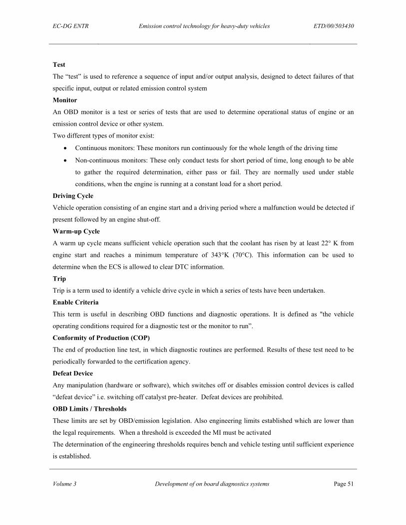
EC-DG ENTR Emission control technology for heavy-duty vehicles ETD/00/503430
Volume 3 Development of on board diagnostics systems Page 51
Test
The “test” is used to reference a sequence of input and/or output analysis, designed to detect failures of that
specific input, output or related emission control system
Monitor
An OBD monitor is a test or series of tests that are used to determine operational status of engine or an
emission control device or other system.
Two different types of monitor exist:
• Continuous monitors: These monitors run continuously for the whole length of the driving time
• Non-continuous monitors: These only conduct tests for short period of time, long enough to be able
to gather the required determination, either pass or fail. They are normally used under stable
conditions, when the engine is running at a constant load for a short period.
Driving Cycle
Vehicle operation consisting of an engine start and a driving period where a malfunction would be detected if
present followed by an engine shut-off.
Warm-up Cycle
A warm up cycle means sufficient vehicle operation such that the coolant has risen by at least 22° K from
engine start and reaches a minimum temperature of 343°K (70°C). This information can be used to
determine when the ECS is allowed to clear DTC information.
Trip
Trip is a term used to identify a vehicle drive cycle in which a series of tests have been undertaken.
Enable Criteria
This term is useful in describing OBD functions and diagnostic operations. It is defined as "the vehicle
operating conditions required for a diagnostic test or the monitor to run”.
Conformity of Production (COP)
The end of production line test, in which diagnostic routines are performed. Results of these test need to be
periodically forwarded to the certification agency.
Defeat Device
Any manipulation (hardware or software), which switches off or disables emission control devices is called
“defeat device” i.e. switching off catalyst pre-heater. Defeat devices are prohibited.
OBD Limits / Thresholds
These limits are set by OBD/emission legislation. Also engineering limits established which are lower than
the legal requirements. When a threshold is exceeded the MI must be activated
The determination of the engineering thresholds requires bench and vehicle testing until sufficient experience
is established.
EC-DG ENTR Emission control technology for heavy-duty vehicles ETD/00/503430
Volume 3 Development of on board diagnostics systems Page 52
Deficiency
Two separate components or systems that are monitored each containing temporary or permanent operating
characteristics that impair the otherwise efficient OBD monitoring of those components or systems or do not
meet all the other detailed requirements for OBD. It could be possible to achieve type approval even when
one or more deficiencies exist.
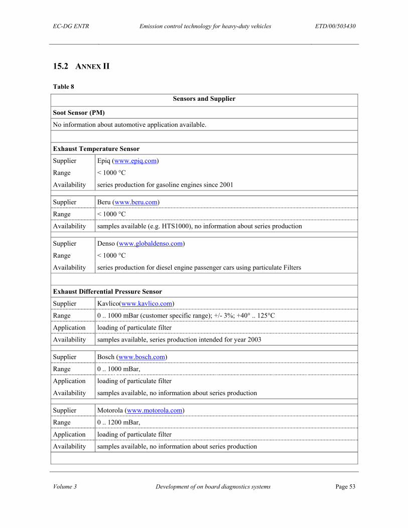
EC-DG ENTR Emission control technology for heavy-duty vehicles ETD/00/503430
Volume 3 Development of on board diagnostics systems Page 53
15.2 ANNEX II
Table 8
Sensors and Supplier
Soot Sensor (PM)
No information about automotive application available.
Exhaust Temperature Sensor
Supplier Epiq (www.epiq.com)
Range < 1000 °C
Availability series production for gasoline engines since 2001
Supplier Beru (www.beru.com)
Range < 1000 °C
Availability samples available (e.g. HTS1000), no information about series production
Supplier Denso (www.globaldenso.com)
Range < 1000 °C
Availability series production for diesel engine passenger cars using particulate Filters
Exhaust Differential Pressure Sensor
Supplier Kavlico(www.kavlico.com)
Range 0 .. 1000 mBar (customer specific range); +/- 3%; +40° .. 125°C
Application loading of particulate filter
Availability samples available, series production intended for year 2003
Supplier Bosch (www.bosch.com)
Range 0 .. 1000 mBar,
Application loading of particulate filter
Availability samples available, no information about series production
Supplier Motorola (www.motorola.com)
Range 0 .. 1200 mBar,
Application loading of particulate filter
Availability samples available, no information about series production
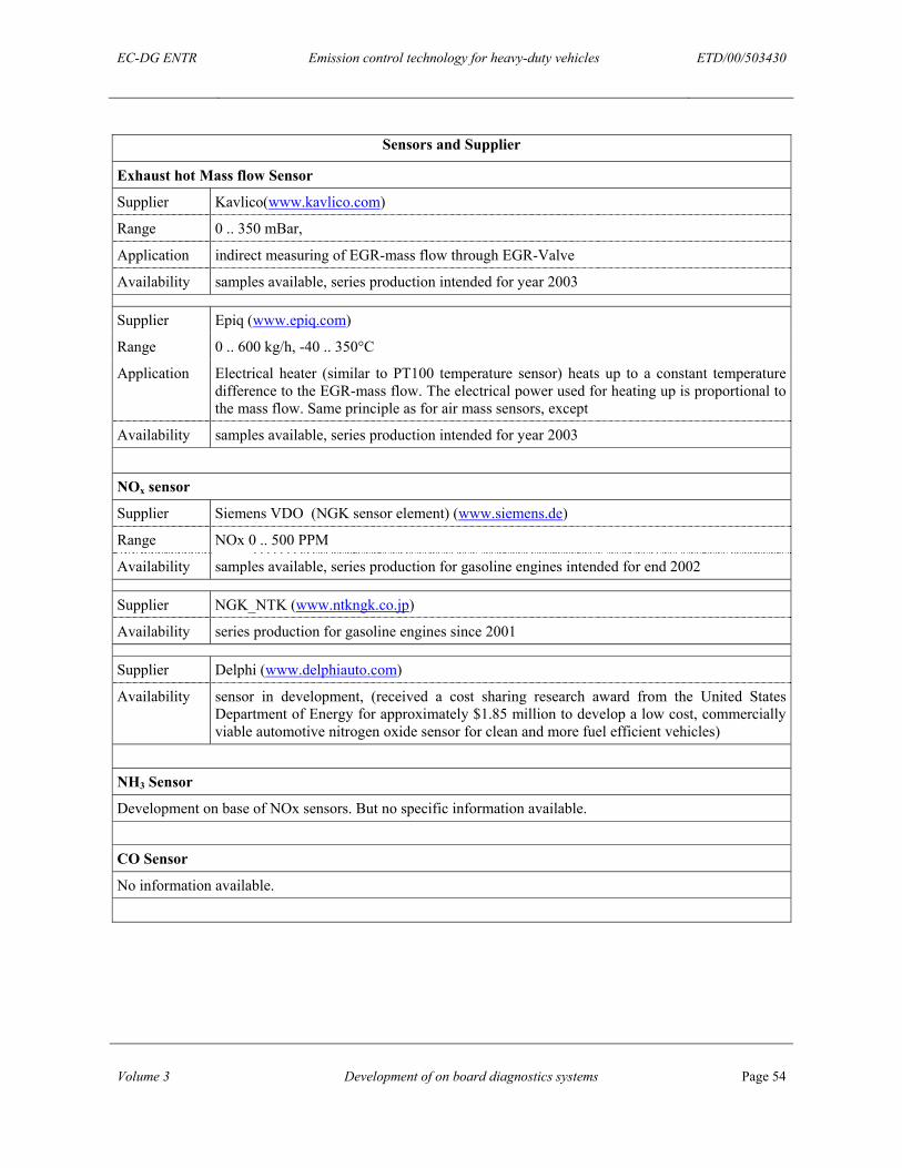
EC-DG ENTR Emission control technology for heavy-duty vehicles ETD/00/503430
Volume 3 Development of on board diagnostics systems Page 54
Sensors and Supplier
Exhaust hot Mass flow Sensor
Supplier Kavlico(www.kavlico.com)
Range 0 .. 350 mBar,
Application indirect measuring of EGR-mass flow through EGR-Valve
Availability samples available, series production intended for year 2003
Supplier Epiq (www.epiq.com)
Range 0 .. 600 kg/h, -40 .. 350°C
Application Electrical heater (similar to PT100 temperature sensor) heats up to a constant temperature difference to the EGR-mass flow. The electrical power used for heating up is proportional to the mass flow. Same principle as for air mass sensors, except
Availability samples available, series production intended for year 2003
NOx sensor
Supplier Siemens VDO (NGK sensor element) (www.siemens.de)
Range NOx 0 .. 500 PPM
Availability samples available, series production for gasoline engines intended for end 2002
Supplier NGK_NTK (www.ntkngk.co.jp)
Availability series production for gasoline engines since 2001
Supplier Delphi (www.delphiauto.com)
Availability sensor in development, (received a cost sharing research award from the United States Department of Energy for approximately $1.85 million to develop a low cost, commercially viable automotive nitrogen oxide sensor for clean and more fuel efficient vehicles)
NH3 Sensor
Development on base of NOx sensors. But no specific information available.
CO Sensor
No information available.
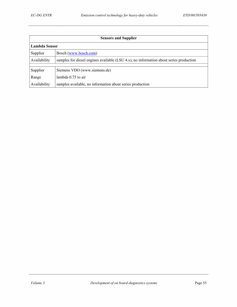
EC-DG ENTR Emission control technology for heavy-duty vehicles ETD/00/503430
Volume 3 Development of on board diagnostics systems Page 55
Sensors and Supplier
Lambda Sensor
Supplier Bosch (www.bosch.com)
Availability samples for diesel engines available (LSU 4.x), no information about series production
Supplier Siemens VDO (www.siemens.de)
Range lambda 0.75 to air
Availability samples available, no information about series production