Embed Size (px)
Citation preview
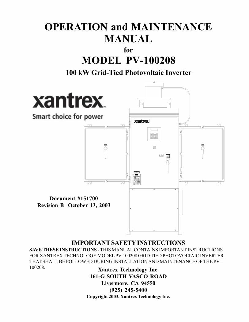
OPERATION and MAINTENANCEMANUAL
forMODEL PV-100208
100 kW Grid-Tied Photovoltaic Inverter
Document #151700Revision B October 13, 2003
IMPORTANT SAFETY INSTRUCTIONSSAVE THESE INSTRUCTIONS - THIS MANUAL CONTAINS IMPORTANT INSTRUCTIONSFOR XANTREX TECHNOLOGY MODEL PV-100208 GRID TIED PHOTOVOLTAIC INVERTERTHAT SHALL BE FOLLOWED DURING INSTALLATION AND MAINTENANCE OF THE PV-100208. Xantrex Technology Inc.
161-G SOUTH VASCO ROADLivermore, CA 94550
(925) 245-5400Copyright 2003, Xantrex Technology Inc.
Product Description ................................................ Section 1Introduction ............................................................................. 1-1Major Components ................................................................. 1-1Control Components ............................................................... 1-2Interconnection Standards Compliance ..................................... 1-3Specifications .......................................................................... 1-4Equipment Symbol ................................................................... 1-4
Safety ............................................................................. Section 2Safety Features ........................................................................ 2-1Isolation Procedure .................................................................. 2-2
Installation And Initial Turn-On ....................... Section 3Isolation Transformer Requirements .......................................... 3-1Torque and Wire Gauge Specifications ..................................... 3-2Installation Instructions ............................................................. 3-2Interconnection Wiring ............................................................. 3-4Initial Turn On Procedure ......................................................... 3-6
Operation ................................................................... Section 4Description of System Operation .............................................. 4-1Operation Features .................................................................. 4-2Operator Interface ................................................................... 4-3Manual State Transitions .......................................................... 4-5Automatic State Transitions ...................................................... 4-6Auto-Restart Feature ............................................................... 4-7Isolation Procedure .................................................................. 4-7Turn-On Procedure ................................................................. 4-7
Troubleshooting ....................................................... Section 5General ................................................................................... 5-1Alarms and Fault Conditions .................................................... 5-1
Preventative Maintenance .................................. Section 6Periodic Maintenance .............................................................. 6-1Isolation Procedure .................................................................. 6-2Turn-On Procedure ................................................................. 6-2
Appendix ...................................................................... Section 7Fault Codes ............................................................................. 7-1Read/Write Parameter Menu .................................................... 7-1Warranty and Certifications ...................................................... 7-4Drawings List .......................................................................... 7-5
Table of Contents
SECTION 1PRODUCT DESCRIPTION
PV-100208 Photovoltaic InverterOperation and Maintenance Manual
Copyright 2003, Xantrex Technology Inc.
DOCUMENT: 151700 1-1
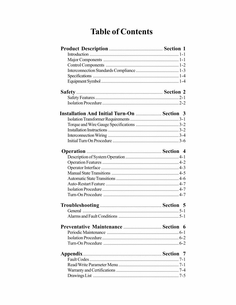
Figure 1-1
INTRODUCTION
The Xantrex Technology Model PV-100208 is a current following grid tied photovoltaic inverter,utilizing state-of-the-art IPM (Intelligent Power Module), insulated gate bi-polar transistors (IGBT’s)and gate drive circuits to allow interface of a photovoltaic array with a utility grid. The PV-100208consists of an inverter bridge, photovoltaic controller, and associated control electronics. The PV-100208 control software provides for complete overall system control with a variety of protection andsafety features.
MAJOR COMPONENTS
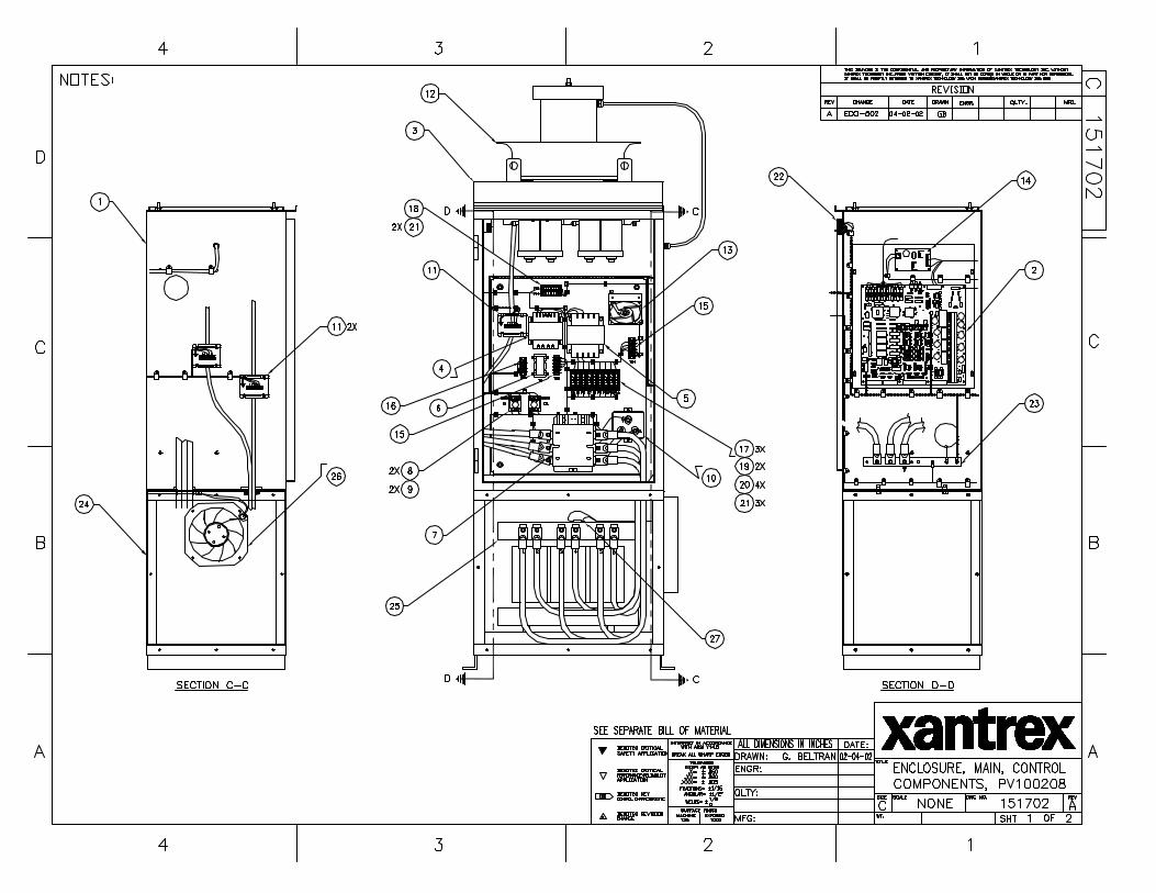
The major components of the PV-100208 are identified in Figure 1-1. Control components are identi-fied in Figure 1-2. For specific control components see Drawing No. 151702 located in Section 7(Appendix).
Main EnclosureThis enclosure is NEMA-3R rated. The PV-100208 main enclosure contains the power electronic in-verter bridge, electrical and electromechanical control components, power supplies, system sensingcircuits, and the PV-100208 embedded control unit. Also found within the main enclosure are some ofthe system protection devices (sense and control power fuses).
SECTION 1PRODUCT DESCRIPTION
PV-100208 Photovoltaic InverterOperation and Maintenance Manual
Copyright 2003, Xantrex Technology Inc.
DOCUMENT: 151700 1-2
CAUTIONThe fuses within the PV-100208 are intended for protecting the PV-100208 controlcircuitry only. They are not intended to provide protection for the PV array or externalcabling.
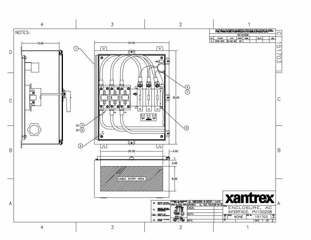
AC Interface EnclosureThis enclosure is NEMA-3R rated. The AC Interface serves as the connection between the isolationtransformer/utility and the PV-100208. This enclosure is where the AC line fuses and AC disconnectswitch reside. For specific control components see Drawing No. 151703 in Section 7 (Appendix).
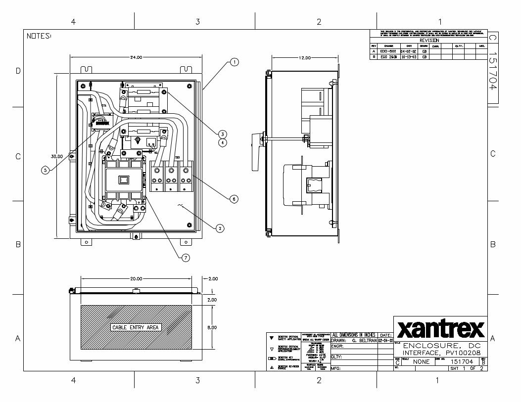
DC Interface EnclosureThis enclosure is NEMA-3R rated. The DC Interface serves as the connection interface between the PVarray and the PV-100208. This enclosure is where the DC disconnect switch and DC contactor reside.For specific control components see Drawing No. 151704 in Section 7 (Appendix).
Power Electronics MatrixThe power electronics converter is located at the top of the PV-100208 Main Enclosure. The matrix iscomprised of switching transistors (IGBTs), transistor gate drive electronics, a laminated power bus,DC capacitor bank, and an aluminum extrusion heat sink with a cooling fan. The fan is located abovethe matrix heatsink.
The PV array is tied logically to the matrix DC bus via the DC interface enclosure. The embeddedcontrol unit manages the transfer of power between the DC bus and the utility grid.
Operator InterfaceThe operator interface is located on the front door of the PV-100208 main enclosure. It consists of anOn/Off switch and a keypad with liquid crystal display for control and monitoring purposes. All inter-face components are NEMA-3R rated. Refer to Section 4 for detailed operation instructions.
Inductor EnclosureThis enclosure is NEMA-3R rated. It contains the necessary filter components to insure the PV-100208line currents and voltages meet IEEE-519 and UL1741 harmonic distortion requirements. Mounted onthe right side of the lower enclosure is an inductor fan to allow cooling of the line filter componentswithin. This enclosure also serves as the mounting base for the PV-100208 main enclosure.
CONTROL COMPONENTS
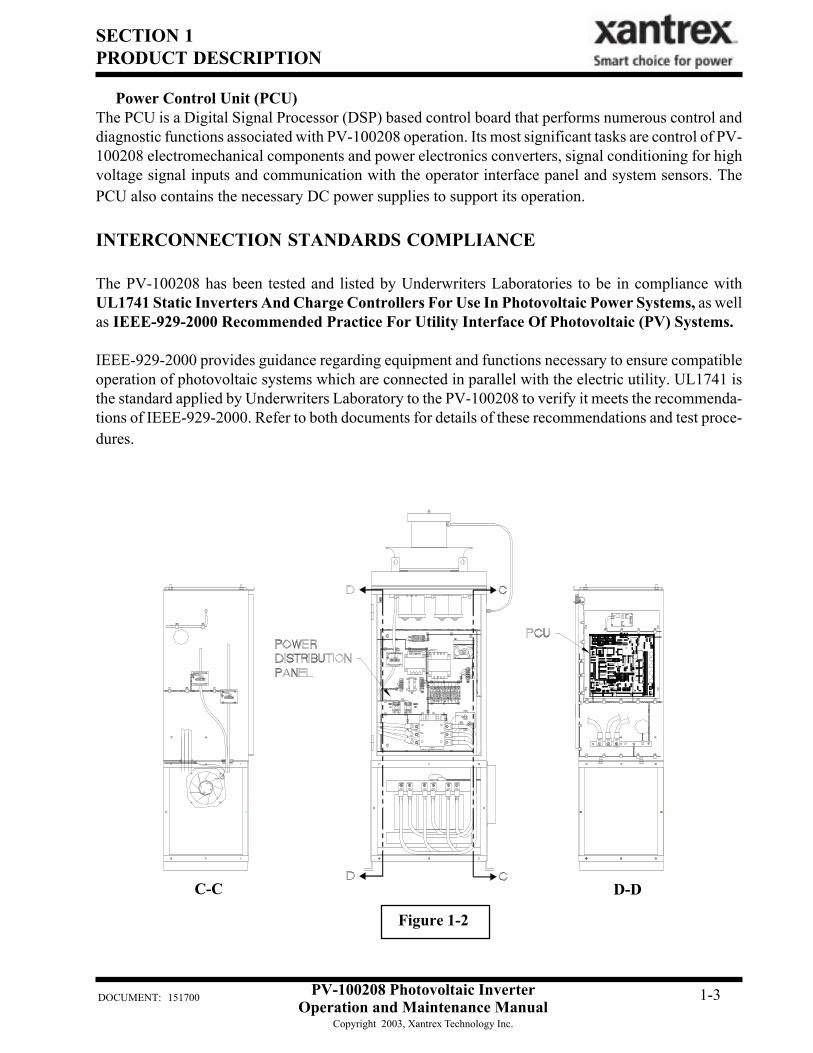
The following assemblies are contained within the PV-100208 main enclosure as shown in Figure 1-2(see Appendix in Section 7).
Power Distribution PanelThis panel contains many of the Electro-mechanical, protective, and control power components neces-sary to support the operation of the PV-100208.
SECTION 1PRODUCT DESCRIPTION
PV-100208 Photovoltaic InverterOperation and Maintenance Manual
Copyright 2003, Xantrex Technology Inc.
DOCUMENT: 151700 1-3
Power Control Unit (PCU)The PCU is a Digital Signal Processor (DSP) based control board that performs numerous control anddiagnostic functions associated with PV-100208 operation. Its most significant tasks are control of PV-100208 electromechanical components and power electronics converters, signal conditioning for highvoltage signal inputs and communication with the operator interface panel and system sensors. ThePCU also contains the necessary DC power supplies to support its operation.
INTERCONNECTION STANDARDS COMPLIANCE
The PV-100208 has been tested and listed by Underwriters Laboratories to be in compliance withUL1741 Static Inverters And Charge Controllers For Use In Photovoltaic Power Systems, as wellas IEEE-929-2000 Recommended Practice For Utility Interface Of Photovoltaic (PV) Systems.
IEEE-929-2000 provides guidance regarding equipment and functions necessary to ensure compatibleoperation of photovoltaic systems which are connected in parallel with the electric utility. UL1741 isthe standard applied by Underwriters Laboratory to the PV-100208 to verify it meets the recommenda-tions of IEEE-929-2000. Refer to both documents for details of these recommendations and test proce-dures.
Figure 1-2
C-C D-D
SECTION 1PRODUCT DESCRIPTION
PV-100208 Photovoltaic InverterOperation and Maintenance Manual
Copyright 2003, Xantrex Technology Inc.
DOCUMENT: 151700 1-4
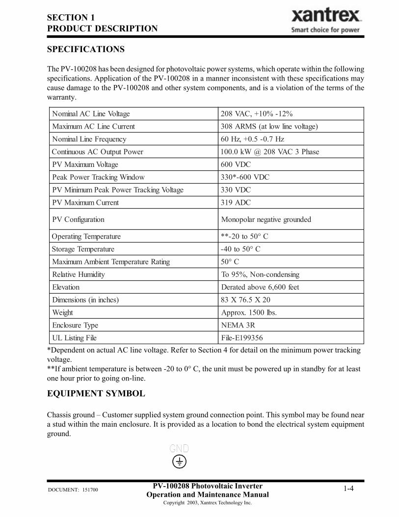
egatloVeniLCAlanimoN %21-%01+,CAV802tnerruCeniLCAmumixaM )egatlovenilwolta(SMRA803
ycneuqerFeniLlanimoN zH7.0-5.0+,zH06rewoPtuptuOCAsuounitnoC [email protected]
egatloVmumixaMVP CDV006wodniWgnikcarTrewoPkaeP CDV006-*033
egatloVgnikcarTrewoPkaePmuminiMVP CDV033tnerruCmumixaMVP CDA913
noitarugifnoCVP dednuorgevitagenraloponoM
erutarepmeTgnitarepO C°05ot02-**erutarepmeTegarotS C°05ot04-
gnitaRerutarepmeTtneibmAmumixaM C°05ytidimuHevitaleR gnisnednoc-noN,%59oT
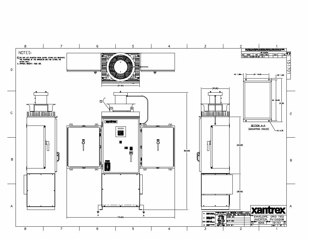
noitavelE teef006,6evobadetareD)sehcnini(snoisnemiD 02X5.67X38
thgieW .sbl0051.xorppAepyTerusolcnE R3AMENeliFgnitsiLLU 653991E-eliF
EQUIPMENT SYMBOL
Chassis ground – Customer supplied system ground connection point. This symbol may be found neara stud within the main enclosure. It is provided as a location to bond the electrical system equipmentground.
*Dependent on actual AC line voltage. Refer to Section 4 for detail on the minimum power trackingvoltage.**If ambient temperature is between -20 to 0° C, the unit must be powered up in standby for at leastone hour prior to going on-line.
SPECIFICATIONS
The PV-100208 has been designed for photovoltaic power systems, which operate within the followingspecifications. Application of the PV-100208 in a manner inconsistent with these specifications maycause damage to the PV-100208 and other system components, and is a violation of the terms of thewarranty.
DOCUMENT: 151700
SECTION 2SAFETY
PV-100208 Photovoltaic InverterOperation and Maintenance Manual
Copyright 2003, Xantrex Technology Inc.
2-1
SAFETY FEATURES
On/Off SwitchThe PV-100208 incorporates a maintained position on/off switch located on the front door of the mainenclosure. Under normal conditions, the on/off switch is in the on position. Turning the switch to theoff position will initiate a controlled shutdown of the PV-100208 and open the A/C contactor withinthe unit. The A/C contactor cannot be closed unless the switch is in the on position. The PV-100208 isprevented from being restarted until the on/off switch is turned back to the on position. Cycling the on/off switch will reset the PV-100208 and attempt to clear any system fault.
Main Enclosure Door Interlock SwitchThe front door of the PV-100208 main enclosure is equipped with an interlock switch to precludeoperation in the event of the front door being opened. It is required that the PV-100208 main enclosuredoor handle be padlocked during normal operation.
Disconnect SwitchesBoth AC & DC switches are equipped with lockout hasps for personnel safety. The switch enclosuredoor will not open while the PV-100208 is running. In addition, the switch handle and shaft provide adoor interlock. The door cannot be opened when the switch is in the “on” position. The PV disconnectswitch is equipped with an auxiliary contact block which enables the switch to be used as a load breakPV disconnect. In the event a disconnect switch is opened while the PV-100208 is processing powerfrom the PV array, the contact block will signal the PCU to stop processing power before the switchopens.
Fault ReportingAny fault conditions are reported to the operator interface. The LCD will display a text description ofthe fault. Refer to Section 5, Troubleshooting, for detailed descriptions of system fault conditions.
PV Ground Fault DetectionThe PV-100208 is equipped with ground fault detection circuitry (see section 3, installation and sec-tion 7, system schematic for further detail). Upon detection of 10 amps of ground fault current, the PV-100208 executes an orderly shutdown, and annunciates a ground fault at the operator interface. The
The PV-100208 enclosure contains exposed high voltage conductors. The enclosuredoors should remain locked, except during maintenance or testing. These servicinginstructions are for use by qualified personnel only. To reduce the risk of electricshock, do not perform any servicing other than that specified in the operatinginstructions unless you are qualified to do so. Do not open the cabinet doors ifextreme moisture is present (rain or heavy dew).
WARNING
The PV-100208 will immediately shutdown if the front door is opened duringoperation. It is required that the PV-100208 main enclosure door handle be pad-locked during normal operations. Please make sure the unit is powered down, andisolated from the utility grid and PV panels, prior to opening the front door. Allow5 minutes for any stored potentials to be discharged, prior to opening the unit.
WARNING
DOCUMENT: 151700
SECTION 2SAFETY
PV-100208 Photovoltaic InverterOperation and Maintenance Manual
Copyright 2003, Xantrex Technology Inc.
2-2
The terminals of the PV input may be energized if the arrays are energized. Inaddition, allow 5 minutes for all capacitors within the enclosure to discharge afterdisconnecting the PV-100208 from AC and DC sources.
WARNING
ISOLATION PROCEDURE
The following procedure should be followed to de-energize the PV-100208 for maintenance:
Anti Island ProtectionA digital phase-shift-loop (PSL) circuit is implemented in the DSP inverter controller to prevent“Islanding” of the PV-100208.
The DSP continuously makes minor adjustments to the power factor phase angle above and belowunity. In the event of a utility outage, these adjustments destabilize the feedback between the inverterand the remaining load, resulting in an over/under frequency or voltage condition. The PV-100208then performs an orderly shutdown. The fault condition will remain until the utility voltage andfrequency have returned to normal for 5 minutes.
This method has been extensively tested and proven to exceed the requirements of UL 1741.
1. Turn the on/off switch to the off position.2. Open the PV array disconnect switch.3. Open the AC interface disconnect switch.4. Open the isolation transformer circuit breaker.5. Install lockout devices on the isolation transformer circuit breaker and PV disconnect switch.
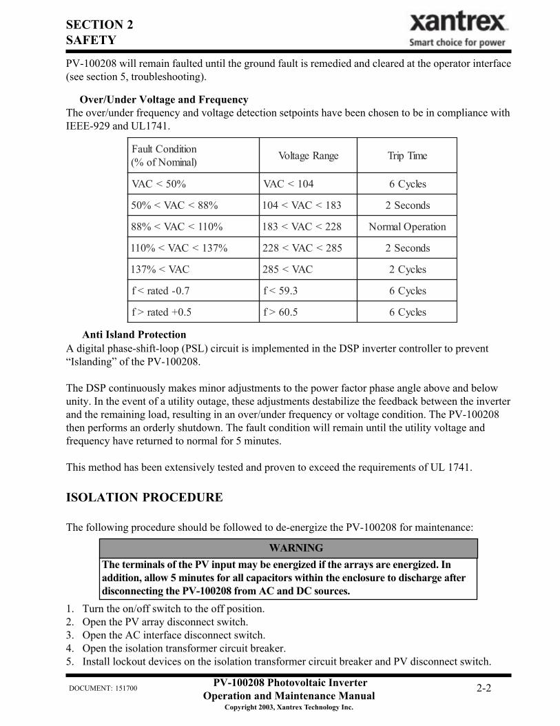
noitidnoCtluaF)lanimoNfo%( egnaRegatloV emiTpirT
%05<CAV CAV < 401 selcyC6
%05 < %88<CAV CAV<401 < 381 sdnoceS2
%88 < CAV < %011 CAV<381 < 822 noitarepOlamroN
%731<CAV<%011 582<CAV<822 sdnoceS2
%731 < CAV 582 < CAV selcyC2
7.0-detar<f 3.95<f selcyC6
5.0+detar>f 5.06>f selcyC6
Over/Under Voltage and FrequencyThe over/under frequency and voltage detection setpoints have been chosen to be in compliance withIEEE-929 and UL1741.
PV-100208 will remain faulted until the ground fault is remedied and cleared at the operator interface(see section 5, troubleshooting).
SECTION 3INSTALLATION AND INITIAL TURN-ON
PV-100208 Photovoltaic InverterOperation and Maintenance Manual
Copyright 2003, Xantrex Technology Inc.
DOCUMENT: 151700 3-1
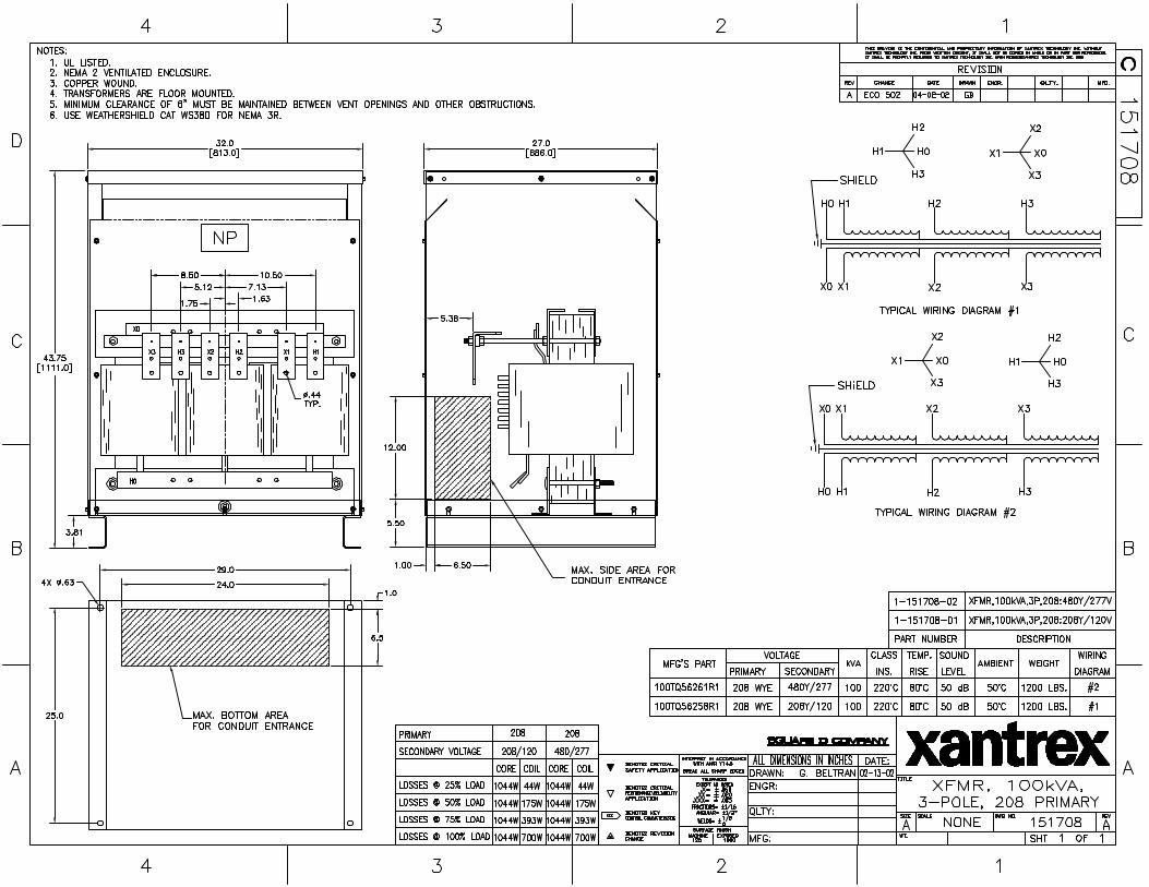
ISOLATION TRANSFORMER REQUIREMENTS
The PV-100208 UL1741 certification requires the 100 kVA WYE/WYE isolation transformer be wiredbetween the inverter AC output and the utility interconnection. This custom 100 kVA isolation trans-former is included with any PV-100208 that requires UL1741 certification (see Appendix in Section 7for transformer dimensions and specifications). If UL1741 and NEC690 is not a requirement of yourPV installation, you may use any standard dry-type isolation transformer as long as the inverter side israted for a minimum of 100 kVA, 208 VAC continuous duty. Contact Xantrex Technology if you haveany questions.
Inverter Side Isolation Transformer RequirementsThe inverter side transformer windings may be configured either DELTA or WYE, and must be ratedfor 208 VAC. If a WYE wound transformer is used to interface with the PV-100208, and the PVarray is grounded, the neutral (X0) must be left floating. If the neutral is tied to ground, the inverterwill suffer irreparable damage.
Utility Side Isolation Transformer RequirementsThe utility side isolation transformer windings may be configured either DELTA or WYE, and must berated for the utility voltage at the point of utility inter-connection. Check with the utility of jurisdictionwhen selecting an isolation transformer configuration. If a WYE wound transformer is used to interfacewith the utility, it is not necessary to connect the neutral (X0) to ground. The PV-100208 is a balanced,three phase, current sourcing inverter, and only operates with the presence of a stable utility voltage.Single phase grounded loads which may be present between the transformer and utility, will maintaintheir existing ground reference at the utility distribution transformer. Grounding the neutral of a WYEwound transformer may create an “open delta” condition, depending on the utility configuration. Thiscondition may keep the PV-100208 from detecting a loss of phase condition on the utility system,which may allow potentially lethal voltage to be present on the open phase wiring.
Contact your Xantrex Technology distributor if you have any questions regarding isolation transformerrequirements.
Check with the local utility of jurisdiction when selecting the winding configura-tion of the isolation transformer. Individual utilities may have unique require-ments related to isolation transformer wiring. Some winding configurations maykeep the PV-100208 from detecting a loss of phase condition on the utility systemwhich may allow potentially lethal voltage to be present on the open phase wir-ings.
WARNING
Xantrex Technology requires installing an isolation transformer between the PV-100208 inverter and the point of utility interconnection. Failure to do so couldresult in catastrophic damage to the PV-100208 as well as the utility distributionsystem and will void the product warranty.
WARNING
SECTION 3INSTALLATION AND INITIAL TURN-ON
PV-100208 Photovoltaic InverterOperation and Maintenance Manual
Copyright 2003, Xantrex Technology Inc.
DOCUMENT: 151700 3-2
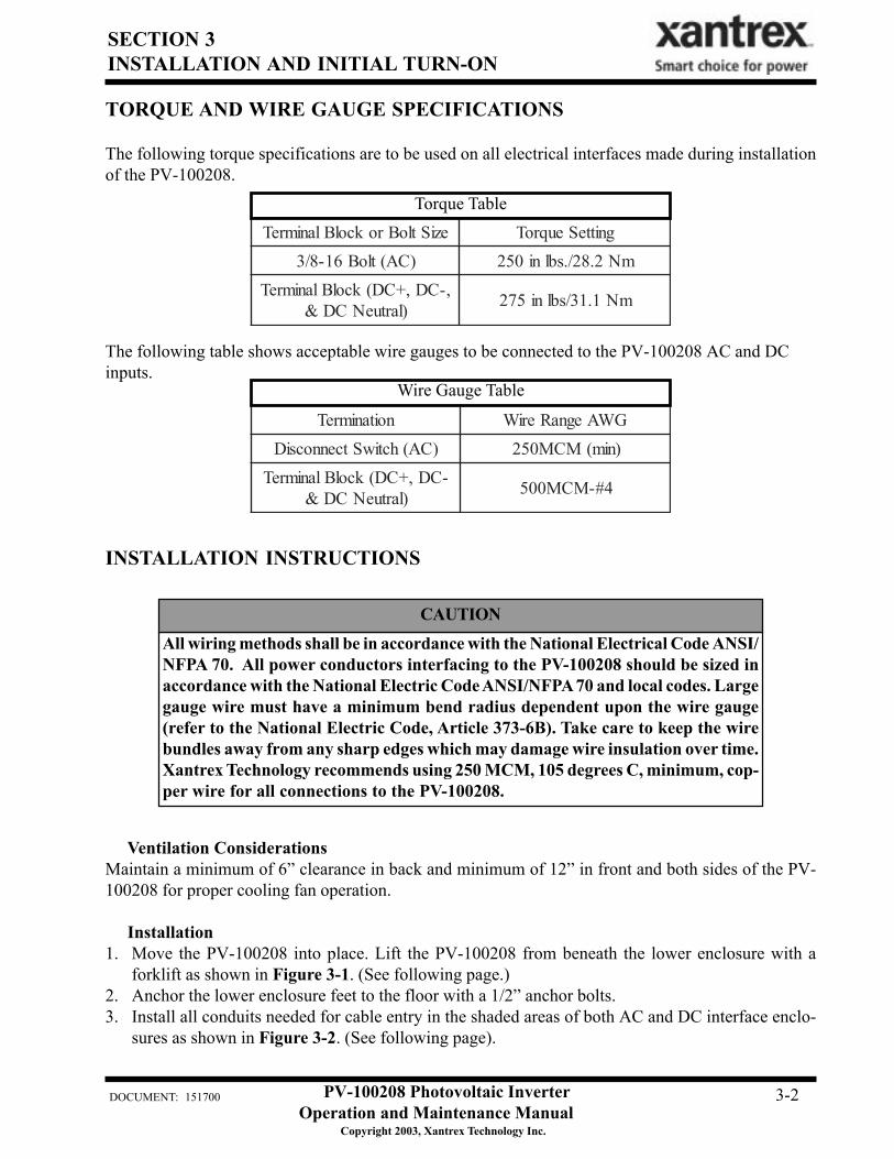
noitanimreT GWAegnaReriW)CA(hctiwStcennocsiD )nim(MCM052
-CD,+CD(kcolBlanimreT)lartueNCD& 4#-MCM005
The following table shows acceptable wire gauges to be connected to the PV-100208 AC and DCinputs.
Wire Gauge Table
TORQUE AND WIRE GAUGE SPECIFICATIONS
The following torque specifications are to be used on all electrical interfaces made during installationof the PV-100208.
eziStloBrokcolBlanimreT gnitteSeuqroT)CA(tloB61-8/3 mN2.82/.sblni052
,-CD,+CD(kcolBlanimreT)lartueNCD& mN1.13/sblni572
Torque Table
All wiring methods shall be in accordance with the National Electrical Code ANSI/NFPA 70. All power conductors interfacing to the PV-100208 should be sized inaccordance with the National Electric Code ANSI/NFPA 70 and local codes. Largegauge wire must have a minimum bend radius dependent upon the wire gauge(refer to the National Electric Code, Article 373-6B). Take care to keep the wirebundles away from any sharp edges which may damage wire insulation over time.Xantrex Technology recommends using 250 MCM, 105 degrees C, minimum, cop-per wire for all connections to the PV-100208.
CAUTION
INSTALLATION INSTRUCTIONS
Ventilation ConsiderationsMaintain a minimum of 6” clearance in back and minimum of 12” in front and both sides of the PV-100208 for proper cooling fan operation.
Installation1. Move the PV-100208 into place. Lift the PV-100208 from beneath the lower enclosure with a
forklift as shown in Figure 3-1. (See following page.)2. Anchor the lower enclosure feet to the floor with a 1/2” anchor bolts.3. Install all conduits needed for cable entry in the shaded areas of both AC and DC interface enclo-
sures as shown in Figure 3-2. (See following page).
SECTION 3INSTALLATION AND INITIAL TURN-ON
PV-100208 Photovoltaic InverterOperation and Maintenance Manual
Copyright 2003, Xantrex Technology Inc.
DOCUMENT: 151700 3-3
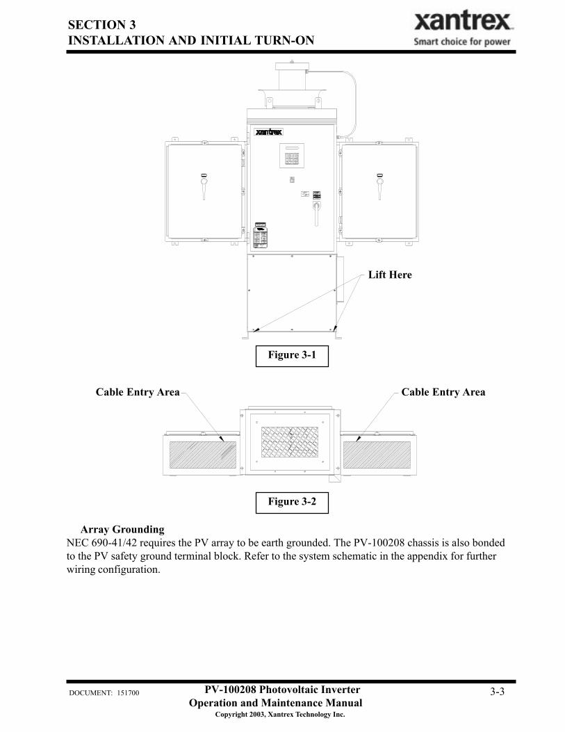
Figure 3-1
Figure 3-2
Cable Entry Area
Lift Here
Cable Entry Area
Array GroundingNEC 690-41/42 requires the PV array to be earth grounded. The PV-100208 chassis is also bondedto the PV safety ground terminal block. Refer to the system schematic in the appendix for furtherwiring configuration.
SECTION 3INSTALLATION AND INITIAL TURN-ON
PV-100208 Photovoltaic InverterOperation and Maintenance Manual
Copyright 2003, Xantrex Technology Inc.
DOCUMENT: 151700 3-4
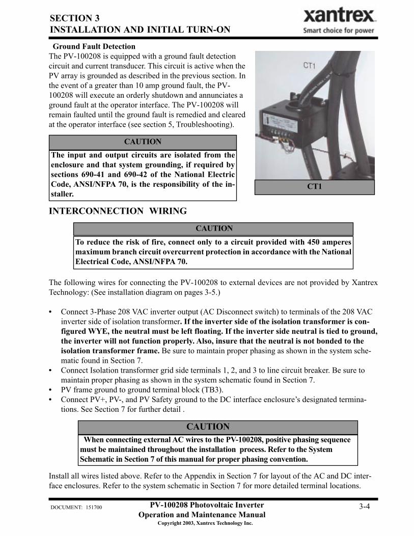
Ground Fault DetectionThe PV-100208 is equipped with a ground fault detectioncircuit and current transducer. This circuit is active when thePV array is grounded as described in the previous section. Inthe event of a greater than 10 amp ground fault, the PV-100208 will execute an orderly shutdown and annunciates aground fault at the operator interface. The PV-100208 willremain faulted until the ground fault is remedied and clearedat the operator interface (see section 5, Troubleshooting).
CT1
The input and output circuits are isolated from theenclosure and that system grounding, if required bysections 690-41 and 690-42 of the National ElectricCode, ANSI/NFPA 70, is the responsibility of the in-staller.
CAUTION
To reduce the risk of fire, connect only to a circuit provided with 450 amperesmaximum branch circuit overcurrent protection in accordance with the NationalElectrical Code, ANSI/NFPA 70.
CAUTION
INTERCONNECTION WIRING
CAUTION When connecting external AC wires to the PV-100208, positive phasing sequencemust be maintained throughout the installation process. Refer to the SystemSchematic in Section 7 of this manual for proper phasing convention.
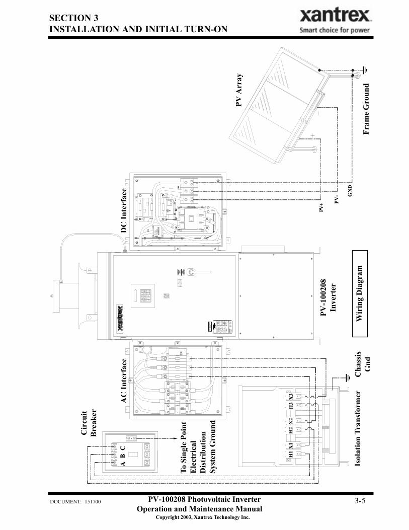
The following wires for connecting the PV-100208 to external devices are not provided by XantrexTechnology: (See installation diagram on pages 3-5.)
• Connect 3-Phase 208 VAC inverter output (AC Disconnect switch) to terminals of the 208 VACinverter side of isolation transformer. If the inverter side of the isolation transformer is con-figured WYE, the neutral must be left floating. If the inverter side neutral is tied to ground,the inverter will not function properly. Also, insure that the neutral is not bonded to theisolation transformer frame. Be sure to maintain proper phasing as shown in the system sche-matic found in Section 7.
• Connect Isolation transformer grid side terminals 1, 2, and 3 to line circuit breaker. Be sure tomaintain proper phasing as shown in the system schematic found in Section 7.
• PV frame ground to ground terminal block (TB3).• Connect PV+, PV-, and PV Safety ground to the DC interface enclosure’s designated termina-
tions. See Section 7 for further detail .
Install all wires listed above. Refer to the Appendix in Section 7 for layout of the AC and DC inter-face enclosures. Refer to the system schematic in Section 7 for more detailed terminal locations.
SECTION 3INSTALLATION AND INITIAL TURN-ON
PV-100208 Photovoltaic InverterOperation and Maintenance Manual
Copyright 2003, Xantrex Technology Inc.
DOCUMENT: 151700 3-5
Isol
atio
n Tr
ansf
orm
er
H1
X1
X2
H2
H3
X3
Cha
ssis
Gnd
Wir
ing
Dia
gram
PV-1
0020
8In
vert
er
To S
ingl
e Po
int
Elec
tric
alD
istri
butio
nSy
stem
Gro
und
PV- G
ND
PV+
A B
C
Cir
cuit
Bre
aker
AC
Inte
rfac
eD
C In
terf
ace
Fram
e Gro
und
PV A
rray
SECTION 3INSTALLATION AND INITIAL TURN-ON
PV-100208 Photovoltaic InverterOperation and Maintenance Manual
Copyright 2003, Xantrex Technology Inc.
DOCUMENT: 151700 3-6
INITIAL TURN ON PROCEDURE
The following must be performed by an approved Technician:
The following procedures are intended to verify correct installation and proper operation of the PV-100208. These steps are to be followed sequentially. Do not continue if any of the steps or results areunclear. Refer to Section 4 for a detailed description of system operation. Refer to Section 5 for faultcondition descriptions and troubleshooting. Refer to Section 7 for detailed system schematics.
Visual Inspection, Isolation Transformer WYE/WYE• Verify the isolation transformer circuit breaker is open.• If a phase rotation meter is available, verify proper phase rotation at the line side of the isolation
transformer circuit breaker.• Insure the neutral on the inverter side is left floating. If the inverter side neutral is tied to ground,
the inverter will not function properly. Also, insure that the neutral is not bonded to theisolation transformer frame.
• Verify the inverter 208 VAC conductors are connected to the isolation transformer.• If the wires are marked, verify they follow the sequence on the line side of the isolation transformer
and circuit breaker.• Verify the utility conductors are properly connected to the isolation transformer.
Visual Inspection, PV-100208• Insure AC and DC disconnect switches are opened.• Remove the front cover from the inductor enclosure, open the door of the main enclosure, and
disconnect enclosures and inspect.• Verify all wire connections are tight.• Inspect the fiber optic cables between the PCU and the matrix driver boards. All fibers should be
snap-locked into their respective receivers/transmitters.• Insure all connector jack screws on the PCU and matrix driver board are tight.• Verify AC phase connections landed at the AC interface enclosure.
Visual Inspection, PV Array Wiring• Verify the PV+, PV-, and PV safety ground are isolated from each other. The safety ground must not
be tied to PV-.• Verify all PV fuses are installed.
Initial Power• Turn the On/Off switch, located on the front door to Off.• With the DC disconnect switch opened, close one of the PV array string disconnect switches.• Carefully measure VDC across the PV +/- terminal block. The value should be the same as at the
PV array string disconnect switch. It should also be positive.• Close the PV disconnect switch.• Carefully measure VDC between the DC contactor negative (-) terminal and the DC switch positive
SECTION 3INSTALLATION AND INITIAL TURN-ON
PV-100208 Photovoltaic InverterOperation and Maintenance Manual
Copyright 2003, Xantrex Technology Inc.
DOCUMENT: 151700 3-7
(+) terminal. The value should be the same as at the PV array string disconnect switch. It shouldalso be positive.
• Open all PV string disconnect switches.• Close the isolation transformer circuit breaker.• Verify 208 VAC voltage across the AC disconnect switch. If a phase rotation meter is available,
verify proper phase rotation at the AC disconnect switch.• Close the AC disconnect switch.• Verify 208 VAC voltage across the AC line fuses F1-3.
System Verification• Upon applying 208 VAC power to the PV-100208, observe the operator interface panel. After
approximately 15 seconds, the panel should finish initialization and will probably report a faultcondition.
• Remedy any faults reported. To clear a fault condition, press the <ENTER> key twice. If the faultmessage does not change, the fault condition is still present. Most likely, any faults seen at thispoint will be related to PV-100208 safety switches. To disable the door interlock switch with themain enclosure door opened, pull the switch shaft out. It will lock in its ‘maintenance’ position.Once all faults are cleared the system will read ‘Sleeping’ or ‘Keyswitch Disable’ depending on theposition of the On/Off switch. To re-enable interlock, push the shaft in and close the door.
• Scroll up the menu until ‘Enter Read Parameter:’ is displayed.• Press <Enter>, then <19>. This is line voltage frequency being read by the PCU. It should read 60.0
+0.5, -0.7.• Verify the On/Off switch is in the ‘Off’ position.• Close the PV array string disconnect switches.• Close the PV-100208 DC disconnect switch.• Press <F2> on the operator interface panel. If the PV voltage is above the PV Start Voltage setpoint,
the second line should read ‘Waking Up’. Once the PV Start Time is exceeded, the PV-100208should transition to ‘Power Tracking’.
• The power tracker was previously limited to 25% of PV-100208 rated power. Once the PV-100208has stabilized operation (approximately 20 seconds), scroll through the main operator interfacepanel menu. Verify all phase voltages and currents are closely balanced.
• Scroll to ‘Enter Read Parameter:’ Press <ENTER> then <17> <ENTER> to view ground faultcurrent value. This value should be equal to or very close to zero. Continue to monitor this value asthe PV-100208 is commanded to higher power levels.
• Enter the write parameter menu and increase the ‘I PPT Max %’ to 50. Exit the write parametermenu and verify all operating values are proper.
• Continue to increment ‘I PPT Max %’ to 100. Depending upon solar conditions, the PV-100208may not operate at full power. If the PV array is not experiencing full sun, the PV maximum powertracker will regulate the PV voltage to maintain maximum PV power output. To determine if thePV-100208 has reached it’s maximum power output, enter <20> at the ‘Enter Read Parameter:’ ‘0’means the PV-100208 has not reached maximum power, contrarily, ‘1’ means the PV-100208 hasreached maximum power and executed the modified peak power tracker to limit output power.
• The PV-100208 is now fully operational.
SECTION 3INSTALLATION AND INITIAL TURN-ON
PV-100208 Photovoltaic InverterOperation and Maintenance Manual
Copyright 2003, Xantrex Technology Inc.
DOCUMENT: 151700 3-8
Power Tracker Fine Tuning:• All PV-100208 operating parameters have been set at the factory, based upon prior experience with
PV arrays.• It is recommended that the PV-100208 be watched during Wake-Up and Sleep Test. If the PV-
100208 cycles between operating and sleeping at either of these times, the condition setpoints arenot set properly (refer to section 4 for detailed description of PV-100208 state transitions). ThePV100208 should not cycle if the setpoints are set properly.
Some field adjustable parameters are password protected and may only be changedby trained service technicians. In particular are parameters relating to utilityprotection setpoints. These have been set in the factory to the limits mandated byUL1741. Any changes to these setpoints should be agreed upon by the local utilityand the equipment owner.
NOTE
Visually inspect the exterior surfaces for any damage (nicks, chips, exposed basemetal and scratches) that may have occurred during shipment or installation.Touch up or recoat using White NISSEN Feltip Paint Marker, or equivalent toprevent rust or corrosion.
NOTE
PV-100208 Photovoltaic InverterOperation and Maintenance Manual
Copyright 2003, Xantrex Technology Inc.
DOCUMENT: 151700 4-1
SECTION 4OPERATION
DESCRIPTION OF SYSTEM OPERATION
OverviewThe PV-100208 is a fully automated grid-tied photovoltaic inverter. Manual interaction or control ofthe inverter is necessary only in the event of a system fault. The following conditions govern PV-100208 operation:
• Stable utility voltage and frequency must be present for all states of operation.• Fault states are automatic from any state of operation. A fault will cause the PV-100208 to imme-
diately stop processing all power. The fault condition will be reported to the operator interface.• The on/off switch, located on the front door of the PV-100208, must be switched to the on position
for all operating states.• Cycling the on/off switch attempts to clear any system faults and return the PV-100208 to normal
operation.
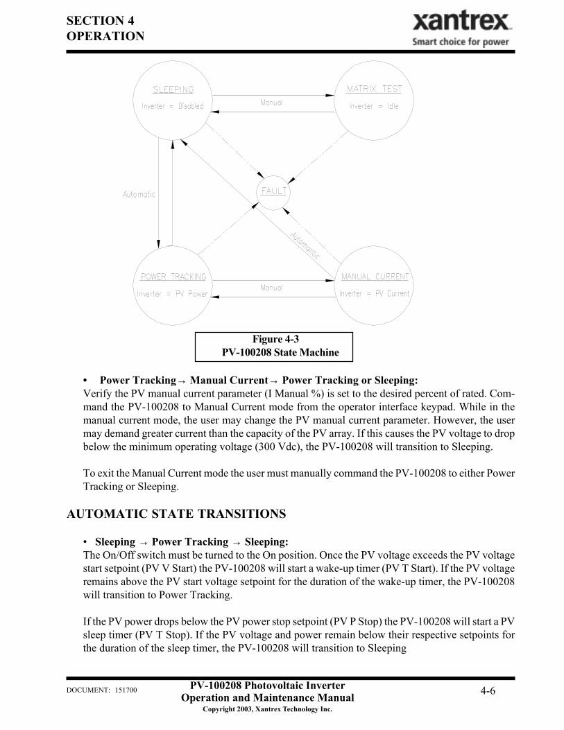
Operating StatesA state machine implemented within the PCU control software governs the operation of the PV100208.There are five steady-state operating states and numerous intermediate transition states. The intermedi-ate transition states provide an orderly progression from one operating state to the next. The user hasthe ability to manually transition the PV-100208 between operating states from the operator interfacekeypad. Manual transitions are initiated by entering a ‘Goal State’, where the goal state is the desiredoperating state. Given all applicable system parameters are within acceptable limits, and the request isvalid within the state machine, the PV-100208 will initiate the proper sequence of operations necessaryto progress to the requested goal state. Refer to Figure 4-3 for a description of valid state transitions.
• Shutdown: The line interface controller is idle. The PCU monitors the status of the PV array andutility grid, waiting in standby until the PV array is available to produce power to the grid.
• Fault: The PV-100208 has encountered a fault condition. When this happens, regardless of the PV-100208 state-of-operation, the PV-100208 will stop processing all power and execute an orderlysystem shutdown. A description of the fault and fault code will appear on the operator interfaceLCD. The Fault state may be cleared from the keypad once the cause of the fault has been cor-rected. See Section 5 for a complete description of all fault codes.
• Manual Current: This operating state is provided to evaluate the existing PV array V-I character-istics. The PV controller regulates a constant amount of PV current as commanded by the user fromthe operator interface keypad, up to the PV current limit of the PV-100208. If the user commandsmore PV current than is available, the DC bus voltage will drop below the minimum bus voltagelevel and the PV-100208 will return to Sleeping mode.
• Matrix Test: This operating state is provided to verify proper operation of the matrix and associ-ated control electronics. There is no power transfer between the PV and utility in this mode.
• Power Tracking: This is the standard operating state of the PV-100208. The PV-100208 maxi-mum power tracker will demand maximum power from the PV array, given sufficient PV irradi-ance.
PV-100208 Photovoltaic InverterOperation and Maintenance Manual
Copyright 2003, Xantrex Technology Inc.
DOCUMENT: 151700 4-2
SECTION 4OPERATION
The user should be aware of the following conditions governing PV-100208 state transitions:
• Utility power must be present for all states of operation. • Fault states are automatic from any state of operation. A fault will cause the PV-100208 to
immediately stop processing all power. The fault condition will be reported to the operatorinterface LCD.
• Most PV-100208 faults are latching and must be cleared at the operator interface keypad beforetransitioning to another operating state.
• The On/Off switch, located on the front door of the PV-100208, must be in the On position forall operating states except Matrix Test, in which case it must be in the Off position.
OPERATION FEATURES
Fixed Unity Power Factor OperationThe Xantrex PV Series grid tied inverters maintains unity power factor during operation. The controlsoftware constantly senses utility voltage, and constructs the output current waveform to match theutility voltage. The PV line of inverters is not capable of operation without the presence of normalutility voltage, nor is it capable of varying the output power factor off unity.
Utility Voltage/Frequency Fault Automatic ResetIn the event of a utility voltage or frequency excursion outside of preset limits, the PV-100208 will stopoperation and annunciate a fault at the operator interface. Once the utility voltage has stabilized withinacceptable limits for a period of at least five minutes, the PV-100208 will automatically clear the faultand resume normal operation. Voltage and frequency fault setpoints are detailed later in this section.
Active Island DetectionMuch concern has been given to the possibility of an inverter causing a ‘utility island’ condition duringa utility power outage. An island condition is defined as grid tied inverter maintaining operation andsupporting a load that has been isolated from the utility power source. This requires the load to beclosely balanced to the output power of the inverter as well as having a resonant frequency close to60Hz. Needless to say, this is an extremely remote possibility. To insure this condition does not occur,the PV-100208 control software contains an active phase-shift-loop algorithm, which destabilizes abalanced load, which may otherwise be capable of maintaining inverter operation in the absence ofutility voltage. This feature has been extensively tested and proven to exceed the safety requirements ofUL-1741 and IEEE-929-2000.
Ground Fault DetectionThe PV-100208 is equipped with a ground fault detection circuit and current transducer. In the event ofa 10 amp ground fault, the PV-100208 will execute an orderly shutdown and annunciates a ground faultat the operator interface. (See Section 5, Troubleshooting).
PV-100208 Photovoltaic InverterOperation and Maintenance Manual
Copyright 2003, Xantrex Technology Inc.
DOCUMENT: 151700 4-3
SECTION 4OPERATION
Current Imbalance DetectionIn the event of phase-to-phase current imbalance of greater than 20% between phases, the inverter willexecute an orderly shutdown, and annunciate a fault at the operator interface. See Section 5, Trouble-shooting, for further information on this fault condition.
DC Overvoltage DetectionIn the event of DC voltage greater than 600Vdc, the PV-100208 will execute an orderly shutdown andannunciate a fault to the operator interface. If DC voltage remains greater than 600Vdc, the PV-100208may be irreparably damaged. See Section 5, troubleshooting for further information on this fault condi-tion.
Peak Power TrackingThe PV-100208 control software employs an active PV peak power tracker designed to maintain maxi-mum power output from the PV array at all times of operation. The peak power voltage point variesprimarily depending upon the temperature of the PV cells. The PV-100208 constantly seeks the opti-mum voltage and current operating points of the PV array to maintain maximum PV power output.Upon PV wake-up, the power tracker will increase power while ramping PV array voltage to the PVmaximum power voltage reference setpoint (PPT V Ref). The change rate is governed by the powerpoint ramp time setpoint (PPT Ramp T). Once the PV voltage is ramped to the reference setpoint, thePCU begins to adjust the commanded PV voltage around the reference setpoint, seeking maximum PVpower. The power tracker may only adjust the operating voltage +/- 20% of PPT V Ref. The PVmaximum power voltage step and update rate are user setable (PPT V Step and PPT Rate, respec-tively).
If available PV power is above the maximum allowable power level of the PV-100208, the powertracker will increase voltage as needed to maintain output power below rated maximum.
The minimum operating voltage of the PV-100208 is 330 VDC. The power tracker will not trackvoltage below this point, regardless of the reference voltage setpoint.
Automatic Sleep TestToward the end of every solar day, the PV-100208 automatically determines when to stop producingpower dependent upon the output power of the inverter. As the net output power of the PV-100208nears zero, a timer is started to allow the inverter to ride through any brief irradiance reductions.
OPERATOR INTERFACE
The operator interface display consists of two main menu levels: The read parameter menu and thewrite parameter menu. The read parameter menu consists of all system parameters, the date and time.These can be viewed any time the PV-100208 has control power.
The write parameter menu consists of a goal state sub-menu, and all system write parameters. The writeparameter menu is password protected and may only be changed by trained service technicians. Inparticular are parameters relating to utility protection setpoints. These have been set in the factory to
PV-100208 Photovoltaic InverterOperation and Maintenance Manual
Copyright 2003, Xantrex Technology Inc.
DOCUMENT: 151700 4-4
SECTION 4OPERATION
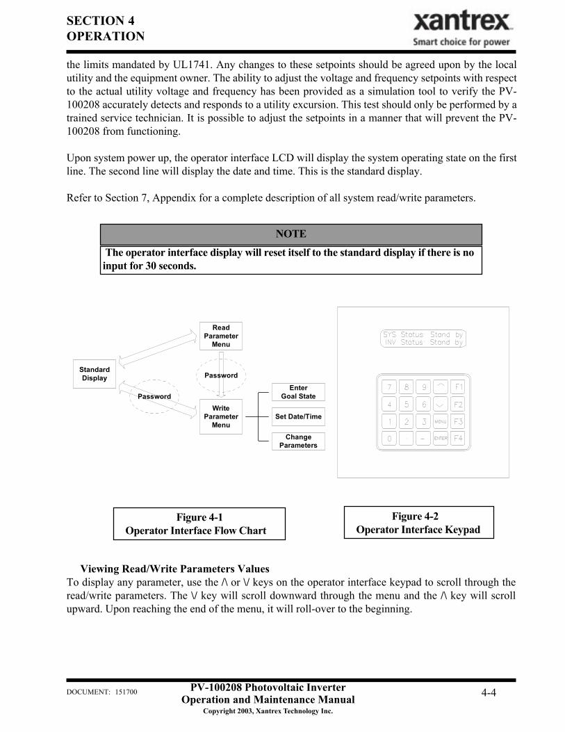
NOTE
The operator interface display will reset itself to the standard display if there is noinput for 30 seconds.
StandardDisplay
Password
ReadParameter
Menu
WriteParameter
Menu
EnterGoal State
Set Date/Time
ChangeParameters
Password
Figure 4-1Operator Interface Flow Chart
Figure 4-2Operator Interface Keypad
the limits mandated by UL1741. Any changes to these setpoints should be agreed upon by the localutility and the equipment owner. The ability to adjust the voltage and frequency setpoints with respectto the actual utility voltage and frequency has been provided as a simulation tool to verify the PV-100208 accurately detects and responds to a utility excursion. This test should only be performed by atrained service technician. It is possible to adjust the setpoints in a manner that will prevent the PV-100208 from functioning.
Upon system power up, the operator interface LCD will display the system operating state on the firstline. The second line will display the date and time. This is the standard display.
Refer to Section 7, Appendix for a complete description of all system read/write parameters.
Viewing Read/Write Parameters ValuesTo display any parameter, use the /\ or \/ keys on the operator interface keypad to scroll through theread/write parameters. The \/ key will scroll downward through the menu and the /\ key will scrollupward. Upon reaching the end of the menu, it will roll-over to the beginning.
PV-100208 Photovoltaic InverterOperation and Maintenance Manual
Copyright 2003, Xantrex Technology Inc.
DOCUMENT: 151700 4-5
SECTION 4OPERATION
Write parameter values are password protected; however, they may be viewed in the read parametermenu without entering a password. From the standard display press the /\ key. The display will read‘Enter Parameter ID:’. Enter the desired write parameter ID, then press the ‘Enter’.
Refer to Section 7: Appendix, for a table of all read/write parameters and their descriptions.
Changing Write Parameter ValuesFrom the standard display or anywhere in the read parameter menu, you may access the write param-eter menu by pressing the <MENU> key. This will ask for a password. Enter the password and pressthe <ENTER> button. Use the /\ or \/ key on the operator interface keypad to scroll through the writeparameters. To change the displayed parameter, press the <ENTER> button. Enter the desired valueand press <ENTER>. If the value entered is outside the acceptable range for the parameter, the originalvalue will remain. To leave the write parameter menu press the <MENU> button repeatedly until thestandard display shows on the LCD.
Refer to Section 7: Appendix, for a table of all read/write parameters and their descriptions.
Commanding Goal State ChangesFrom the standard display press the <MENU> key. This will ask for a password. Enter the passwordand press the <ENTER> button. The LCD will prompt ‘Change Goal State?’. Press <ENTER> again.The goal state menu will show on the LCD. Scroll through the goal state menu with the /\ or \/ keysuntil the desired goal state is reached. Press <ENTER>. The LCD will prompt: ‘Press F4 to Confirm’.Press <F4> and the PV-100208 will transition to this goal state. If the goal state requested violates theconditions of the state machine, the PV-100208 will remain in the previous state of operation.
Setting the Date and TimeFrom the standard display enter the write parameter menu (see previous). From the ‘Change GoalState?’ prompt, scroll up with the /\ key until date/time parameter is reached. Press the enter key. Thedate/time will be replaced with an underscore. Enter the proper date/time in a six digit format. Forexample: The date is entered month-day-year: April 28, 2002 is entered 042802 <ENTER>. The timeis entered in military hours-minutes-seconds: 4:30 pm is entered 163000 <ENTER>. If the date/time isentered incorrectly the original value will remain. Press <MENU> to return to the standard display.
MANUAL STATE TRANSITIONSRefer to previous sections on commanding PV-100208 goal states.
• Sleeping → Matrix Test → Sleeping:Turn the On/Off switch to the Off position. Command the PV-100208 to Matrix Test. Once the userhas completed the test, command the PV-100208 to Sleeping. If the On/Off switch is turned to Onwhile the PV-100208 is in the Matrix Test state, the PV-100208 will transition to Sleeping.
PV-100208 Photovoltaic InverterOperation and Maintenance Manual
Copyright 2003, Xantrex Technology Inc.
DOCUMENT: 151700 4-6
SECTION 4OPERATION
Figure 4-3 PV-100208 State Machine
• Power Tracking→ Manual Current→ Power Tracking or Sleeping:Verify the PV manual current parameter (I Manual %) is set to the desired percent of rated. Com-mand the PV-100208 to Manual Current mode from the operator interface keypad. While in themanual current mode, the user may change the PV manual current parameter. However, the usermay demand greater current than the capacity of the PV array. If this causes the PV voltage to dropbelow the minimum operating voltage (300 Vdc), the PV-100208 will transition to Sleeping.
To exit the Manual Current mode the user must manually command the PV-100208 to either PowerTracking or Sleeping.
AUTOMATIC STATE TRANSITIONS
• Sleeping → Power Tracking → Sleeping:The On/Off switch must be turned to the On position. Once the PV voltage exceeds the PV voltagestart setpoint (PV V Start) the PV-100208 will start a wake-up timer (PV T Start). If the PV voltageremains above the PV start voltage setpoint for the duration of the wake-up timer, the PV-100208will transition to Power Tracking.
If the PV power drops below the PV power stop setpoint (PV P Stop) the PV-100208 will start a PVsleep timer (PV T Stop). If the PV voltage and power remain below their respective setpoints forthe duration of the sleep timer, the PV-100208 will transition to Sleeping
PV-100208 Photovoltaic InverterOperation and Maintenance Manual
Copyright 2003, Xantrex Technology Inc.
DOCUMENT: 151700 4-7
SECTION 4OPERATION
• Any State → Fault:If the PV-100208 encounters a fault, regardless of operating state, it will transition to the Faultstate. The PV-100208 will remain in this state until the fault condition has been remedied andcleared via the front panel.
A description of the fault will show on the first line of the operator interface LCD. The second lineof the LCD will read ‘Clear Fault?’. To clear a fault press <ENTER>. The PV-100208 will transi-tion to Sleeping. If the fault does not clear, the fault condition has not been corrected. If the ‘ClearFault?’ message is not shown on the second line of the LCD, scroll through the read parametermenu with the /\ or \/ keys until the message appears.
AUTO-RESTART FEATURE
In the event of a utility voltage or frequency surge or sag, which causes the inverter to shut down, thePV-100208 will automatically transition to a fault condition. Once the utility recovers for a period offive minutes, the PV-100208 will automatically clear the fault, then resume normal operation.
ISOLATION PROCEDURE
The following procedure should be followed to de-energize the PV-100208 for maintenance:
1. Turn the On/Off switch to the Off position.2. Open the PV array disconnect switches.3. Open the AC disconnect switch.4. Open the isolation transformer circuit breaker.5. Install lockout devices on the isolation transformer circuit breaker and PV disconnect switch.
WARNING The terminals of the disconnect switches may be energized if the arrays are ener-gized. In addition, allow 5 minutes for all capacitors within the main enclosure todischarge after disconnecting the PV-100208 from AC and DC sources.
TURN-ON PROCEDURE
Refer to Section 3 for a detailed first-time turn on procedure.
1. Remove any lockout devices from the isolation transformer circuit breaker and PV disconnectswitch.
2. Close the isolation transformer circuit breaker.3. Close the AC disconnect switch.4. Close PV array disconnect switches.5. Turn the On/Off switch to the On position.
After a 15 second initialization period, the PV-100208 will automatically transition to ‘Waking Up’,given the PV voltage is greater than the PV V Start setpoint.
SECTION 5TROUBLESHOOTING
DOCUMENT: 151700 PV-100208 Photovoltaic InverterOperation and Maintenance Manual
Copyright 2003, Xantrex Technology Inc.
5-1
GENERAL
In the event of a fault, the PV-100208 will annunciate the condition at the operator interface. The PV-100208 will execute an orderly shutdown and remain faulted until the fault is cleared (manually orautomatically).
In general, the operator should respond to any PV-100208 fault as follows:1. The source of the fault should be sought by referring to the following chart.2. Rectify the fault condition and attempt to clear the fault by cycling the on/off switch.3. If the problem cannot be corrected, note and write down the fault code and description, then contact
your Xantrex Technology distributor for assistance or service.
ALARM AND FAULT CONDITIONS
WARNINGLethal energy may be stored within each matrix assembly. Use extreme cautionwhen troubleshooting. After disconnect all sources of power, wait at least 5 minutesfor internal capacitors to discharge.
(H) - Fault triggered by hardware.(S) - Fault triggered by software.
0000 - No FaultsNo fault conditions are detected.
002C - Matrix Over-Temperature (S)The temperature of the matrix aluminum heat sink exceeded 85°C.
Possible causes:• External cooling fan inoperable• Air flow on heat sink impeded due to accumulation of debris• Operation above rated ambient temperature for an extended period of time
002E - State Machine Failure (S)Software has encountered an undefined state.
Attempt to clear the fault by either cycling control power or pressing the black reset button in the lowerleft corner of the PCU. If the fault is sustained, replacement or service of the PCU will be necessary.
002F – Parameter Out Of Date (S)Software has determined that the system variables within the operator interface panel do not match theones in the PCU. Generally this fault may be cleared and normal operation resumed.
0031 - Ground Current Fault (S)The earth safety ground current has exceeded the maximum programmed value (Max Gnd Flt I).
SECTION 5TROUBLESHOOTING
DOCUMENT: 151700 PV-100208 Photovoltaic InverterOperation and Maintenance Manual
Copyright 2003, Xantrex Technology Inc.
5-2
Possible causes:• Inspect the PV array for ground faults.• CT3 defective: Troubleshoot the ground fault CT3, located on the power distribution panel of the
main enclosure (see system schematic drawing in Section 7), using the procedures described in faultYY27.
0032 - PV Overvoltage (S)The PV voltage has exceeded the maximum programmed limit (PV Max Volt).
Check the PV input voltage at the PV disconnect switch. If the voltage is below 600 VDC, clear thealarm and restart the PV-100208.
0040 - In Programming Mode (S)System is in reload PROM mode.
0042 - Bad Memory (S)The static memory test failed upon system initialization. This fault is generally transient in nature.
Attempt to clear the fault by either cycling control power or pressing the black reset button in the lowerleft corner of the PCU. If the fault is sustained, replacement or service of the PCU will be necessary.
0045 – Line Matrix Failure to Turn On (S) 0046 – Line Matrix Failure to Turn Off (S)Software was not able turn on or turn off the indicated switching matrix.
Attempt to clear the fault by either cycling control power or pressing the black reset button in the lowerleft corner of the PCU. If the fault is sustained, replacement or service of the PCU will be necessary.
0061 – Line AC Frequency Too Low (S)The AC line frequency fell below the allowable limit.
This fault is self-clearing. Once the utility frequency has recovered within the acceptable operatingrange, the PV-100208 will automatically clear this fault and resume normal operation after 5 minutes. Ifthe fault will not clear, verify the adjustable setpoint is below the actual utility frequency. If the fault issustained, contact your Xantrex Technology distributor for assistance or service.
0062 - Line AC Frequency Too High (S)The AC frequency exceeded the allowable limit.
This fault is self-clearing. Once the utility frequency has recovered within the acceptable operatingrange, the PV-100208 will automatically clear this fault and resume normal operation after 5 minutes. Ifthe fault will not clear, verify the adjustable setpoint is above the actual utility frequency. If the fault issustained, contact your Xantrex Technology distributor for assistance or service.
SECTION 5TROUBLESHOOTING
DOCUMENT: 151700 PV-100208 Photovoltaic InverterOperation and Maintenance Manual
Copyright 2003, Xantrex Technology Inc.
5-3
0063 - AC Voltage Too Low (S)The AC Inverter voltage fell below the minimum programmed limit (Min AC Volt).
This problem was caused by the utility. Clear the fault and restart the PV-100208.
Possible causes:• High momentary load which forces the inverter to current limit• Fuses F1, F2, F3, F4, F5 or F6 blown• SSR-1 inoperable• Contactor K1 inoperable• Utility voltage fell below the allowable limit.This fault is self-clearing. Once the utility voltage has recovered within the acceptable operating range,the PV-100208 will automatically clear this fault and resume normal operation after 5 minutes. If thefault will not clear, verify the adjustable setpoint is below the actual utility voltage. If the fault is sus-tained, contact your Xantrex Technology distributor for assistance or service.
0064 - AC Voltage Too High (S)The inverter controller voltage exceeded the maximum-programmed limit (Max AC Volt).
Possible causes:• SSR-1 inoperable• Contactor K1 inoperable• Utility voltage exceeded the allowable limit.This fault is self-clearing. Once the utility voltage has recovered within the acceptable operating range,the PV-100208 will automatically clear this fault and resume normal operation after 5 minutes. If thefault will not clear, verify the adjustable setpoint is above the actual utility voltage. If the fault is sus-tained, contact your Xantrex Technology distributor for assistance or service.
012A - Interrupt Time-Out (S)The PCU was not able to service the interrupt for approximately 1 second.
Attempt to clear the fault and restart the PV-100208 by pressing the black reset button on the lower leftcorner of the PCU. If the fault is sustained, replacement or service of the PCU will be necessary.
0230 – Door Interlock Switch Open (H)The door interlock lock switch located in the inside upper left corner of the main enclosure door is open.
If the switch is closed and the fault still registers on the front panel, isolate the PV-100208 from externalpower, then:
• Verify continuity across the switch contact block while the switch is closed.• Verify continuity between PCU-J2-5 and PCU-J3-3.
0430 - PV Auxiliary Switch Open (H)
SECTION 5TROUBLESHOOTING
DOCUMENT: 151700 PV-100208 Photovoltaic InverterOperation and Maintenance Manual
Copyright 2003, Xantrex Technology Inc.
5-4
The dry contact auxiliary switch mounted to the PV disconnect switch has been toggled. The auxil-iary switch should be opened when the PV disc switch is open. If the fault will not clear when the PVdisconnect switch is closed:• Isolate PV-100208 from utility power.• Close PV disc switch and check continuity between PCU J3-3 and PCU J2-7. If there is no continu-
ity, inspect wiring between the PCU and the auxiliary switch (see page 3 of the system schematic forfurther detail).
XX25 - Line Gate Drive Fault (S)One of the IGBT gate drive boards signaled the PCU that there was a fault. The particular device atwhich the fault was detected is indicated by the first two digits of the fault code, as follows:
XX: 01 = Phase A+ 02 = Phase A-04 = Phase B+ 08 = Phase B-10 = Phase C+ 20 = Phase C-
If more than one phase faults simultaneously, the error code will contain the summation of phase faultvalues. For example, if phase A+ and B+ fault simultaneously, the error will read 0525.
Make sure the fiber optics for the device and matrix in question are properly connected to the driverboard. Similarly, make sure the fiber is properly connected at the PCU.
Clear the fault and restart the PV-100208. If the fault is sustained, contact your Xantrex Technologydistributor for assistance or service.
YY27 - Line Over-Current Fault (S)Current in one phase of the matrix has exceeded the allowable limit. The faulted phase is indicated by thefirst two digits of the fault code, as follows:
YY: 01 = Phase A02 = Phase B04 = Phase C
If more than one phase faults simultaneously, the error code will contain the summation of phase faultvalues. For example, if phase A and C fault simultaneously, the error will read 0527.
Possible causes:• AC system wiring short: Inspect the AC power system for short circuits.• PCU Power Supply is defective: Verify +/-15Vdc sources, referenced to analog ground, on the
PCU. There are labeled test points on the PCU circuit board. Note: There are two isolated +15Vdcpower supplies labeled +15Vdc and +15Vdc Drv. The +15Vdc Drv power supply provides powerfor the matrix driver boards only.
• Faulty CT wiring: Verify the wiring between the PCU power supply and the CT is properly con-nected and undamaged. Refer to page 3 of the system schematic in Section 7.
• CT defective: Locate the current transducer for the matrix and phase in question (see control com-ponents drawing in Section 7). With a digital multi-meter measure the voltage from CT pins 1, 2, and3 to chassis ground. Pins 1 and 3 should read approximately +15 and -15Vdc respectively. Thesevoltages are sourced directly from the PCU. Pin 2 should read less than 20mV when no current ispassing through the CT window. If Pin 2 reads greater than 20mV, and the supply voltages are onPins 1 and 3 are correct, the CT may be damaged.
SECTION 5TROUBLESHOOTING
DOCUMENT: 151700 PV-100208 Photovoltaic InverterOperation and Maintenance Manual
Copyright 2003, Xantrex Technology Inc.
5-5
Clear the fault and restart the PCU. If the fault is sustained contact your Xantrex Technology distributorfor assistance or service.
0828 – PV Over-Current Fault (S)Current through the PV CT has exceeded the allowable limit.
Possible causes:• PV system wiring short: Inspect the PV power system for short circuits.• PCU Power Supply is defective: Verify +/-15Vdc sources, referenced to analog ground, on the
PCU. There are labeled test points on the PCU circuit board. Note: There are two isolated +15Vdcpower supplies labeled +15Vdc and +15Vdc Drv. The +15Vdc Drv power supply provides powerfor the matrix driver boards only.
• Faulty CT wiring: Verify the wiring between the PCU and the CT is properly connected and undam-aged. Refer to the system schematic in Section 7.
• CT defective: Locate the current transducer for the PV leg in question (see control componentsdrawing in Section 7). With a digital multi-meter measure the voltage from CT pins 1, 2, and 3 tochassis ground. Pins 1 and 3 should read approximately +15 and -15Vdc respectively. These volt-ages are sourced directly from the PCU. Pin 2 should read less than 20mV when no current ispassing through the CT window. If Pin 2 reads greater than 20mV, and the supply voltages are onPins 1 and 3 are correct, the CT may be damaged
Clear the fault and restart the PCU. If the fault is sustained contact your Xantrex Technology distributorfor assistance or service.
8021 - DC Bus Voltage High (H)The DC Bus voltage has exceeded the maximum allowable limit.
This fault is generally transient in nature. Clear the fault and attempt to restart the PV-100208.
SECTION 6PREVENTATIVE MAINTENANCE
PV-100208 Photovoltaic InverterOperation and Maintenance Manual
Copyright 2003, Xantrex Technology Inc.
DOCUMENT: 151700 6-1
PERIODIC MAINTENANCE
Xantrex Technology recommends that the following preventative maintenance be carried out on thePV-100208:
Monthly intervals or as required:
Visually inspect the exterior surfaces for any damage (nicks, chips, exposed basemetal and scratches). Touch up or recoat using White NISSEN Feltip Paint Marker,or equivalent to prevent rust or corrosion.
NOTE
Aluminum Extrusion HeatsinkAccumulation of dirt and debris on the aluminum extrusion heatsink and fan will decrease theability to transfer heat, which can cause the PV-100208 to shutdown on over-temperature alarms.Inspect the aluminum extrusion heatsink and fan for accumulation of dirt and debris. Clean ifdebris is present.
Fan OperationVerify proper operation of the heatsink cooling fan, located above the matrix heatsink. The fanoperates when the K1 contactor is closed. Remove any debris from the fan.
Internal Circulation Fan:Verify the internal circulation fan is operating whenever there is utility power applied to thePV-100208.
Inductor Enclosure Cooling Fan:Verify this fan operates whenever the PV-100208 is processing power.
Six month intervals:(See Isolation Procedure located on page 6-2, and perform prior to the following)
Enclosure SealsInspect the enclosure access panel seal. If damaged, replace with equivalent closed cell foamgasket. Call your Xantrex Technology distributor for factory replacements or specifications.
Electrical ConnectionsInspect the condition of all wiring within the PV-100208. Inspect all wire crimps and connec-tions for damage caused from high temperature. Check for corrosion. Replace any damagedwires. Verify all mechanical connections are sufficiently tightened. Verify all conduction sur-faces are clean and free of corrosion.
SECTION 6PREVENTATIVE MAINTENANCE
PV-100208 Photovoltaic InverterOperation and Maintenance Manual
Copyright 2003, Xantrex Technology Inc.
DOCUMENT: 151700 6-2
1. Turn the on/off switch to the off position.2. Open the PV array disconnect switch.3. Open the AC interface disconnect switch.4. Open the isolation transformer circuit breaker.5. Install lockout devices on the isolation transformer circuit breaker and PV disconnect switch.
TURN-ON PROCEDURE
Refer to Section 3 for a detailed first-time turn on procedure.
1. Remove any lockout devices from the isolation transformer circuit breaker and PV disconnectswitch.
2. Close the isolation transformer circuit breaker.3. Close the AC interface disconnect switch.4. Close the PV array disconnect switch.5. Turn the on/off switch to the on position.
After a 15 second initialization period and a 5 minute wake up period, the PV-100208 will automati-cally begin power tracking, given the PV voltage is greater than the PV start voltage setpoint.
The terminals of the PV input may be energized if the arrays are energized. Inaddition, allow 5 minutes for all capacitors within the enclosure to discharge af-ter shutting down the PV-100208.
WARNING
Mechanical electrical connections will loosen over time. This is caused primarily by thermalcycling during normal operation. As connections loosen, electrical impedance will increase atthe connection, eventually leading to fire and component damage. It is critical to check allelectrical connections every six months.
Inductor Enclosure Access the inductor enclosure and remove any accumulated dirt and debris. Vacuum enclosurewhenever dust or dirt is present.
ISOLATION PROCEDURE
The following procedure should be followed to de-energize the PV-100208 for maintenance:
SECTION 7APPENDIX
PV-100208 Photovoltaic InverterOperation and Maintenance Manual
Copyright 2003, Xantrex Technology Inc.
DOCUMENT: 151700 7-1
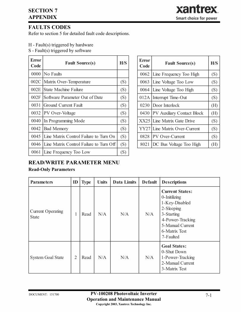
FAULTS CODESRefer to section 5 for detailed fault code descriptions.
H - Fault(s) triggered by hardwareS - Fault(s) triggered by software
rorrEedoC )s(ecruoStluaF S/H
0000 stluaFoN
C200 erutarepmeT-revOxirtaM )S(
E200 eruliaFenihcaMetatS )S(
F200 etaDfotuOretemaraPerawtfoS )S(
1300 tluaFtnerruCdnuorG )S(
2300 egatloV-revOVP )S(
0400 edoMgnimmargorPnI )S(
2400 yromeMdaB )S(
5400 nOnruToteruliaFlortnoCxirtaMeniL )S(
6400 ffOnruToteruliaFlortnoCxirtaMeniL )S(
1600 woLooTycneuqerFeniL )S(
rorrEedoC )s(ecruoStluaF S/H
2600 hgiHooTycneuqerFeniL )S(
3600 woLooTegatloVeniL )S(
4600 hgiHooTegatloVeniL )S(
A210 tuO-emiTtpurretnI )S(
0320 kcolretnIrooD )H(
0340 kcolBtcatnoCyrailixuAVP )H(
52XX evirDetaGxirtaMeniL )S(
72YY tnerruC-revOxirtaMeniL )S(
8280 tnerruC-revOVP )S(
1208 hgiHooTegatloVsuBCD )H(
sretemaraP DI epyT stinU stimiLataD tluafeD snoitpircseD
gnitarepOtnerruCetatS 1 daeR A/N A/N A/N
:setatStnerruCgnizilitinI-0
delbasiD-yeK-1gnipeelS-2
gnitratS-3gnikcarT-rewoP-4tnerruClaunaM-5
tseTxirtaM-6detluaF-7
etatSlaoGmetsyS 2 daeR A/N A/N A/N
:setatSlaoGnwoDtuhS-0
gnikcarT-rewoP-1tnerruClaunaM-2
tseTxirtaM-3
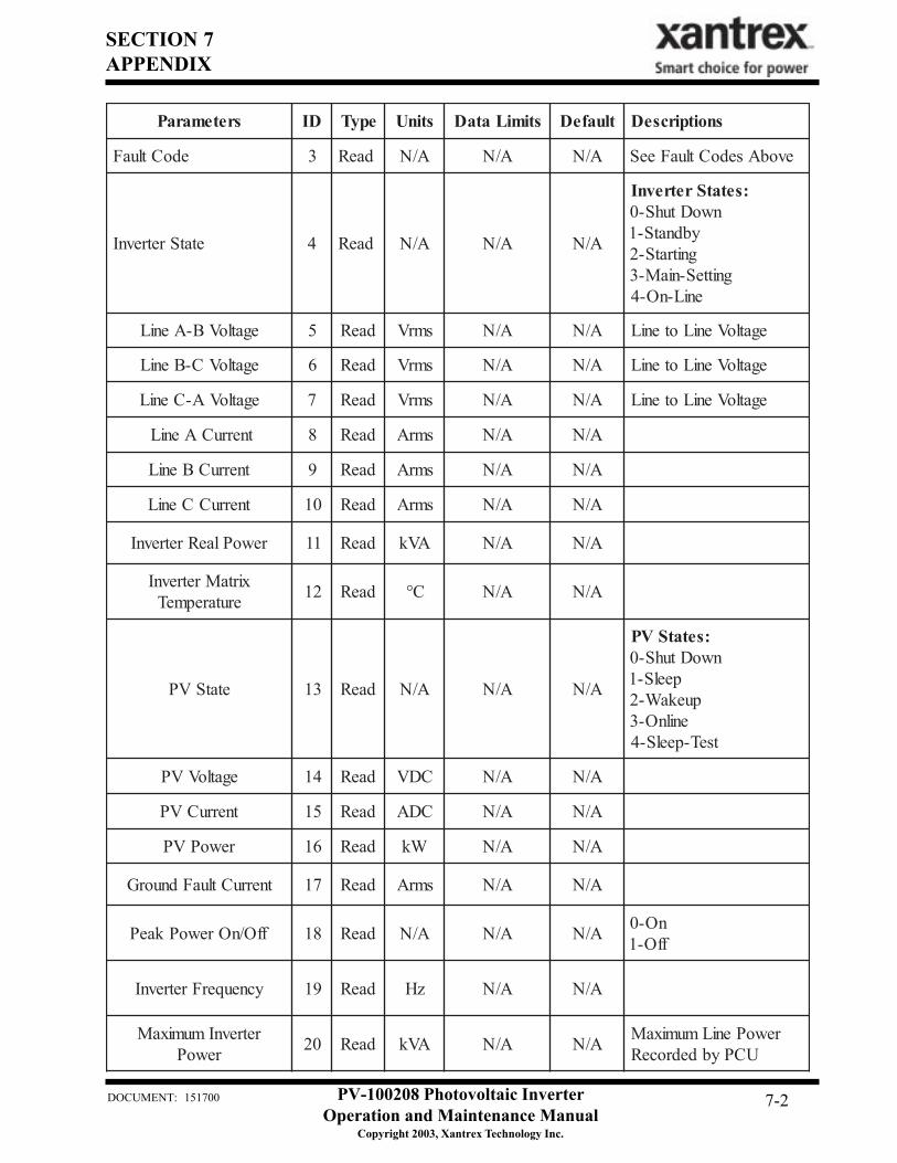
READ/WRITE PARAMETER MENURead-Only Parameters
SECTION 7APPENDIX
PV-100208 Photovoltaic InverterOperation and Maintenance Manual
Copyright 2003, Xantrex Technology Inc.
DOCUMENT: 151700 7-2
sretemaraP DI epyT stinU stimiLataD tluafeD snoitpircseD
edoCtluaF 3 daeR A/N A/N A/N evobAsedoCtluaFeeS
etatSretrevnI 4 daeR A/N A/N A/N
:setatSretrevnInwoDtuhS-0
ybdnatS-1gnitratS-2
gnitteS-niaM-3eniL-nO-4
egatloVB-AeniL 5 daeR smrV A/N A/N egatloVeniLoteniL
egatloVC-BeniL 6 daeR smrV A/N A/N egatloVeniLoteniL
egatloVA-CeniL 7 daeR smrV A/N A/N egatloVeniLoteniL
tnerruCAeniL 8 daeR smrA A/N A/N
tnerruCBeniL 9 daeR smrA A/N A/N
tnerruCCeniL 01 daeR smrA A/N A/N
rewoPlaeRretrevnI 11 daeR AVk A/N A/N
xirtaMretrevnIerutarepmeT 21 daeR C° A/N A/N
etatSVP 31 daeR A/N A/N A/N
:setatSVPnwoDtuhS-0
peelS-1puekaW-2
enilnO-3tseT-peelS-4
egatloVVP 41 daeR CDV A/N A/N
tnerruCVP 51 daeR CDA A/N A/N
rewoPVP 61 daeR Wk A/N A/N
tnerruCtluaFdnuorG 71 daeR smrA A/N A/N
ffO/nOrewoPkaeP 81 daeR A/N A/N A/N nO-0ffO-1
ycneuqerFretrevnI 91 daeR zH A/N A/N
retrevnImumixaMrewoP 02 daeR AVk A/N A/N rewoPeniLmumixaM
UCPybdedroceR
SECTION 7APPENDIX
PV-100208 Photovoltaic InverterOperation and Maintenance Manual
Copyright 2003, Xantrex Technology Inc.
DOCUMENT: 151700 7-3
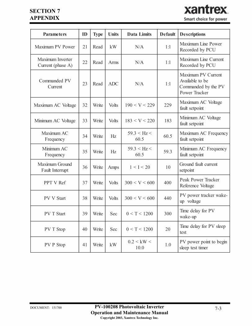
sretemaraP DI epyT stinU stimiLataD tluafeD snoitpircseD
rewoPVPmumixaM 12 daeR Wk A/N 1:1 rewoPeniLmumixaMUCPybdedroceR
retrevnImumixaM)Aesahp(tnerruC 22 daeR smrA A/N 1:1 tnerruCeniLmumixaM
UCPybdedroceR
VPdednammoCtnerruC 32 daeR CDA A/N 1:1
tnerruCVPmumixaMebotelbaliavA
VPehtybdednammoCrekcarTrewoP
egatloVCAmumixaM 23 etirW stloV 922<V<091 922 egatloVCAmumixaMtnioptestluaf
egatloVCAmuminiM 33 etirW stloV 022<V<381 381 egatloVCAmuminiMtnioptestluaf
CAmumixaMycneuqerF 43 etirW zH <zH<3.95
5.06 5.06 ycneuqerFCAmumixaMtnioptestluaf
CAmuminiMycneuqerF 53 etirW zH <zH<3.95
5.06 3.95 ycneuqerFCAmuminiMtnioptestluaf
dnuorGmumixaMtpurretnItluaF 63 etirW spmA 02<I<1 01 tnerructluafdnuorG
tnioptes
feRVTPP 73 etirW stloV 006<V<003 004 rekcarTrewoPkaePegatloVecnerefeR
tratSVVP 83 etirW stloV 006<V<003 044 -ekawrekcartrewopVPegatlovpu
tratSTVP 93 etirW ceS 0021<T<0 003 VProfyaledemiTpu-ekaw
potSTVP 04 etirW ceS 0021<T<0 02 peelsVProfyaledemiTtset
potSPVP 14 etirW Wk <Wk<2.00.01 0.1 nigebottnioprewopVP
remittsetpeels
SECTION 7APPENDIX
PV-100208 Photovoltaic InverterOperation and Maintenance Manual
Copyright 2003, Xantrex Technology Inc.
DOCUMENT: 151700 7-4
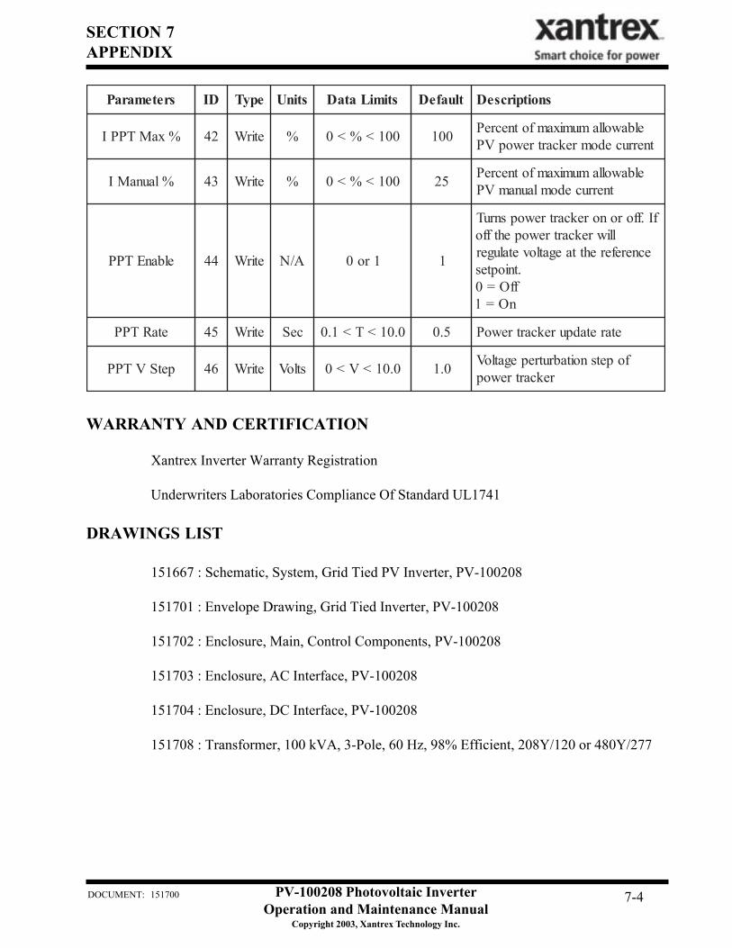
sretemaraP DI epyT stinU stimiLataD tluafeD snoitpircseD
%xaMTPPI 24 etirW % 001<%<0 001 elbawollamumixamfotnecrePtnerrucedomrekcartrewopVP
%launaMI 34 etirW % 001<%<0 52 elbawollamumixamfotnecrePtnerrucedomlaunamVP
elbanETPP 44 etirW A/N 1ro0 1
fI.fforonorekcartrewopsnruTlliwrekcartrewopehtffo
ecnereferehttaegatlovetaluger.tnioptes
ffO=0nO=1
etaRTPP 54 etirW ceS 0.01<T<1.0 5.0 etaretadpurekcartrewoP
petSVTPP 64 etirW stloV 0.01<V<0 0.1 fopetsnoitabrutrepegatloVrekcartrewop
WARRANTY AND CERTIFICATION
Xantrex Inverter Warranty Registration
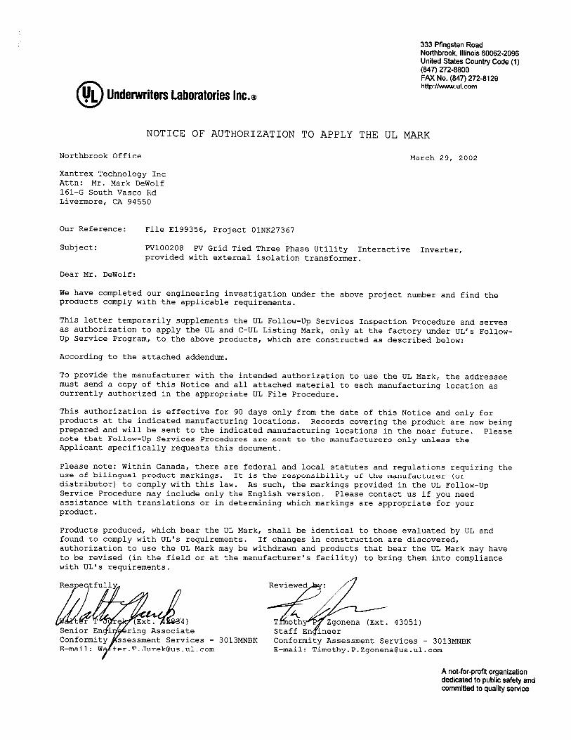
Underwriters Laboratories Compliance Of Standard UL1741
DRAWINGS LIST
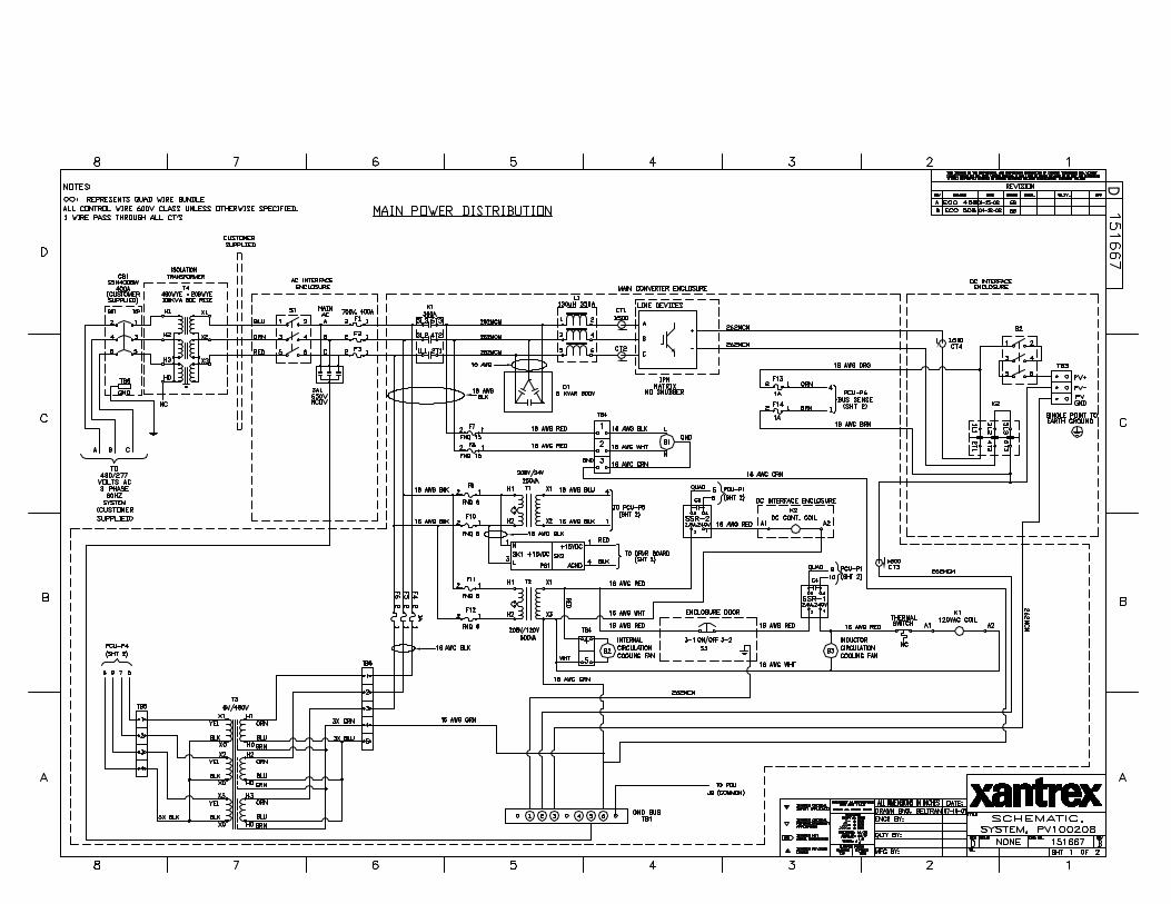
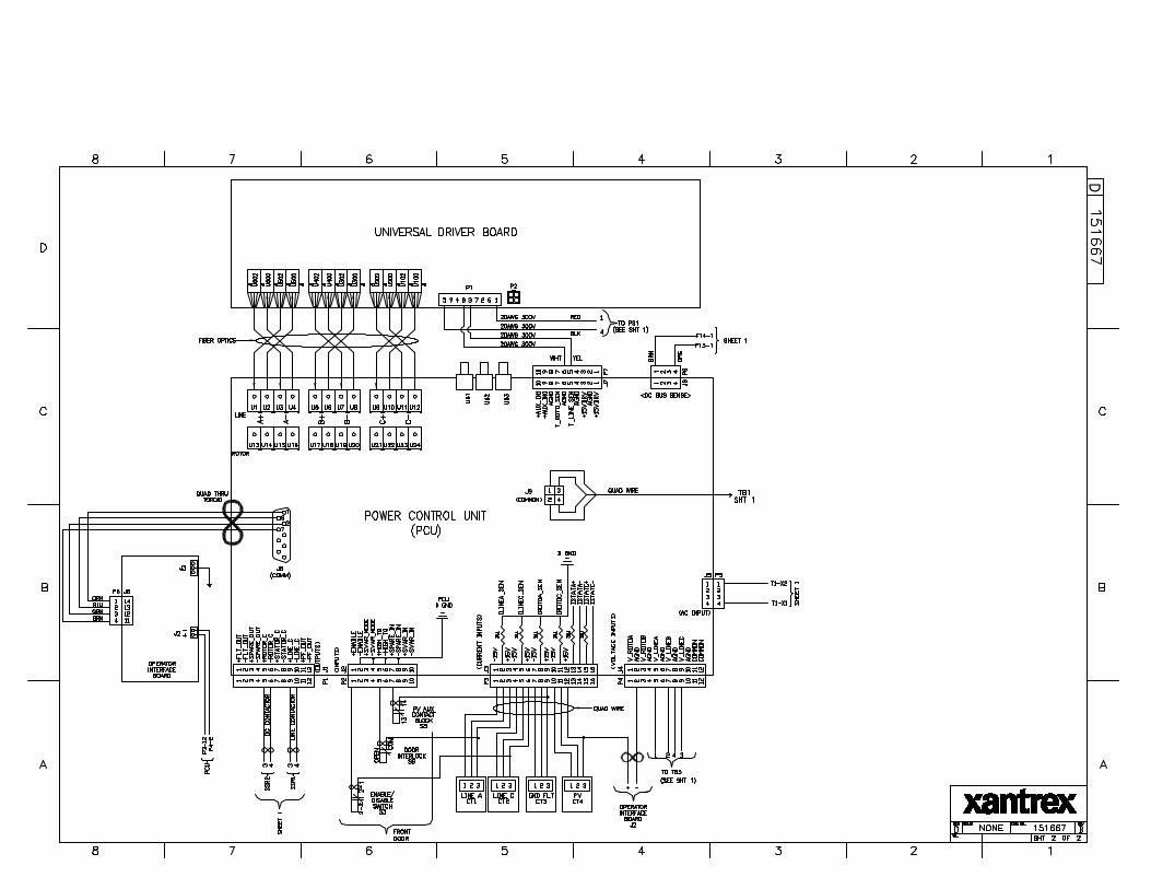
151667 : Schematic, System, Grid Tied PV Inverter, PV-100208
151701 : Envelope Drawing, Grid Tied Inverter, PV-100208
151702 : Enclosure, Main, Control Components, PV-100208
151703 : Enclosure, AC Interface, PV-100208
151704 : Enclosure, DC Interface, PV-100208
151708 : Transformer, 100 kVA, 3-Pole, 60 Hz, 98% Efficient, 208Y/120 or 480Y/277
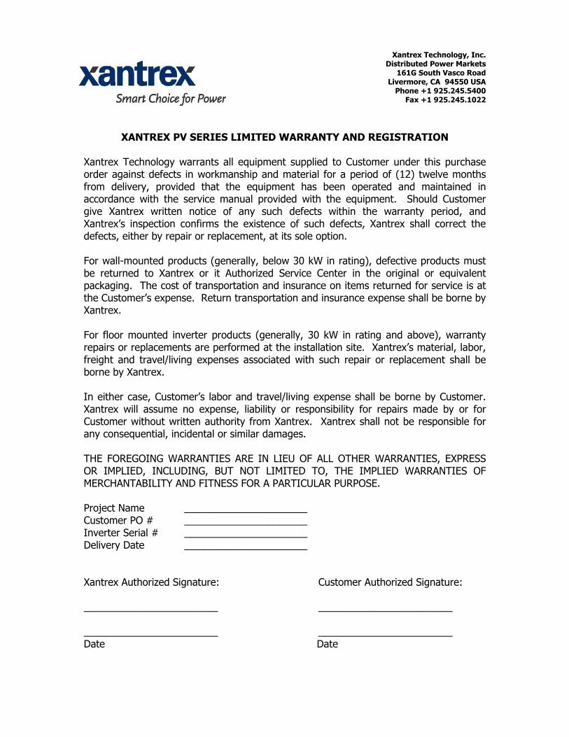
Xantrex Technology, Inc. Distributed Power Markets
161G South Vasco Road Livermore, CA 94550 USA
Phone +1 925.245.5400 Fax +1 925.245.1022
XANTREX PV SERIES LIMITED WARRANTY AND REGISTRATION
Xantrex Technology warrants all equipment supplied to Customer under this purchase order against defects in workmanship and material for a period of (12) twelve months from delivery, provided that the equipment has been operated and maintained in accordance with the service manual provided with the equipment. Should Customer give Xantrex written notice of any such defects within the warranty period, and Xantrex’s inspection confirms the existence of such defects, Xantrex shall correct the defects, either by repair or replacement, at its sole option. For wall-mounted products (generally, below 30 kW in rating), defective products must be returned to Xantrex or it Authorized Service Center in the original or equivalent packaging. The cost of transportation and insurance on items returned for service is at the Customer’s expense. Return transportation and insurance expense shall be borne by Xantrex. For floor mounted inverter products (generally, 30 kW in rating and above), warranty repairs or replacements are performed at the installation site. Xantrex’s material, labor, freight and travel/living expenses associated with such repair or replacement shall be borne by Xantrex. In either case, Customer’s labor and travel/living expense shall be borne by Customer. Xantrex will assume no expense, liability or responsibility for repairs made by or for Customer without written authority from Xantrex. Xantrex shall not be responsible for any consequential, incidental or similar damages. THE FOREGOING WARRANTIES ARE IN LIEU OF ALL OTHER WARRANTIES, EXPRESS OR IMPLIED, INCLUDING, BUT NOT LIMITED TO, THE IMPLIED WARRANTIES OF MERCHANTABILITY AND FITNESS FOR A PARTICULAR PURPOSE. Project Name ______________________ Customer PO # ______________________ Inverter Serial # ______________________ Delivery Date ______________________ Xantrex Authorized Signature: Customer Authorized Signature: ________________________ ________________________ ________________________ ________________________ Date Date
D
D
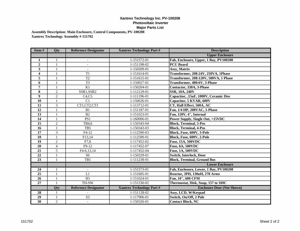
Xantrex Technology Inc. PV-100208 Photovoltaic Inverter
Major Parts ListAssembly Description: Main Enclosure, Control Components, PV-100208Xantrex Technology Assembly # 151702
Item # Qty Reference Designator Xantrex Technology Part # DescriptionUpper Enclosure
1 1 - 1-151572-01 Fab, Enclosure, Upper, 1 Bay, PV1002082 1 - 1-151198-02 PCU Board3 1 - 1-150209-01 Assy, Matrix4 1 T1 1-151614-01 Transformer, 208:24V, 250VA, 1Phase5 1 T2 1-151615-01 Transformer, 208:120V, 500VA, 1 Phase6 1 T3 1-150027-01 Transformer, 480:6V, 3-Phase7 1 K1 1-150204-01 Contactor, 330A, 3-Phase8 2 SSR1,SSR2 1-112129-01 SSR, 10A, 240V9 2 C4,C5 1-111196-01 Capacitor, .15uF, 1000V, Ceramic Disc10 1 C1 1-150626-01 Capacitor, 5 KVAR, 600V11 3 CT1,CT2,CT3 1-113712-01 CT, Hall Effect, 500A, AC12 1 B1 1-151187-01 Fan, 1/4 HP, 208VAC, 1-Phase13 1 B2 1-151023-01 Fan, 120V, 4", Internal14 1 PS1 1-160006-01 Power Supply, Single Out, +15VDC15 2 TB4,6 1-150343-04 Block, Terminal, 5-Pos16 1 TB5 1-150343-03 Block, Terminal, 4-Pos17 3 F4-12 1-112590-03 Block, Fuse, 600V, 3-Pole18 1 F13,14 1-112590-01 Block, Fuse, 600V, 2-Pole19 2 F7,8 1-117452-02 Fuse, 15A, 500VDC20 4 F9-12 1-117452-07 Fuse, 6A, 500VDC21 5 F4-6,13,14 1-117452-04 Fuse, 1A, 500VDC22 1 S6 1-150329-01 Switch, Interlock, Door23 1 TB1 1-111238-01 Block, Terminal, Ground Bus
Lower Enclosure24 1 - 1-151573-01 Fab, Enclosure, Lower, 1 Bay, PV10020825 1 L1 1-151605-01 Reactor, 3PH, 130uH, 278 Arms26 1 B3 1-151024-01 Fan, 10", 600 CFM27 1 TH-SW 1-151530-02 Thermostat, Disk, Snap, 157 to 169C
Qty Reference Designator Xantrex Technology Part # Enclosure Door (Not Shown)28 1 - 1-151128-02 Assy, LCD, W/Keypad29 1 S3 1-117906-01 Switch, On/Off, 2 Pole30 2 - 1-150326-01 Contact Block, NC
151702 Sheet 2 of 2
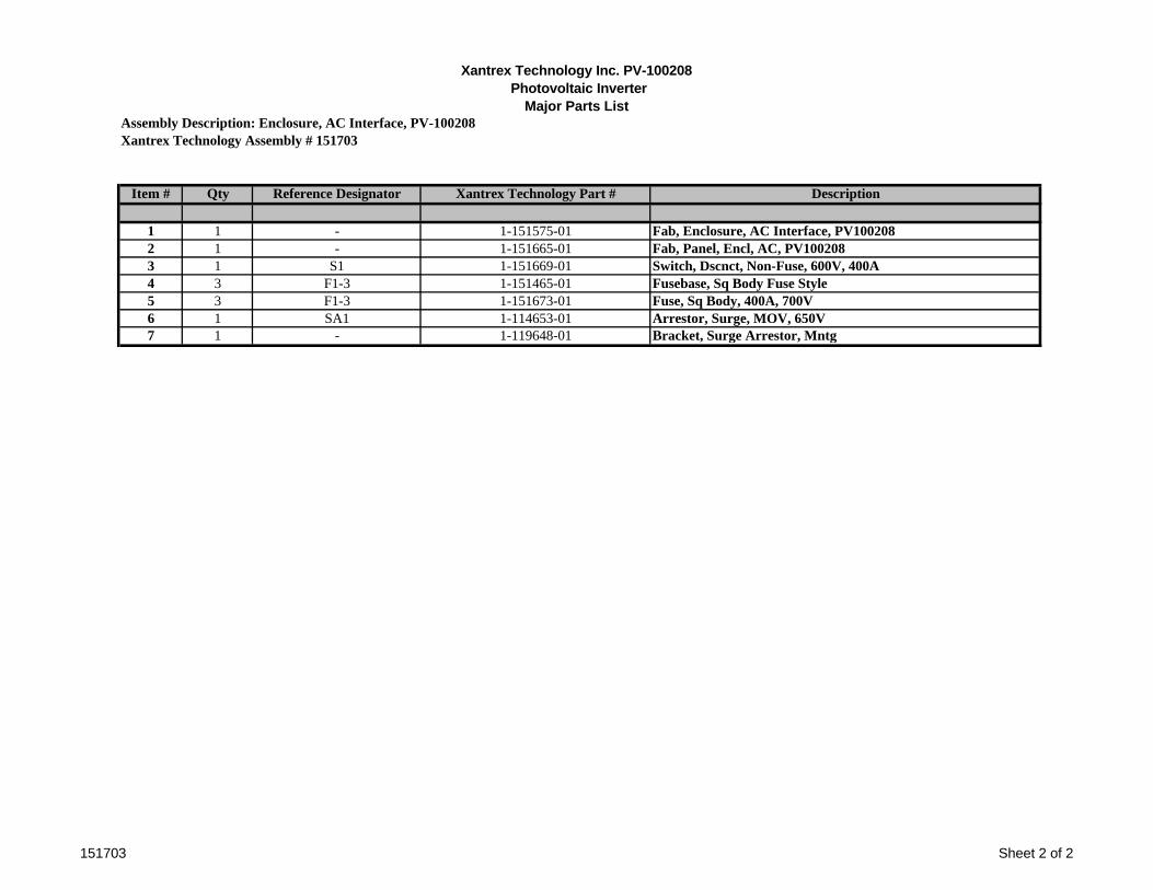
Xantrex Technology Inc. PV-100208 Photovoltaic Inverter
Major Parts ListAssembly Description: Enclosure, AC Interface, PV-100208Xantrex Technology Assembly # 151703
Item # Qty Reference Designator Xantrex Technology Part # Description
1 1 - 1-151575-01 Fab, Enclosure, AC Interface, PV1002082 1 - 1-151665-01 Fab, Panel, Encl, AC, PV1002083 1 S1 1-151669-01 Switch, Dscnct, Non-Fuse, 600V, 400A4 3 F1-3 1-151465-01 Fusebase, Sq Body Fuse Style5 3 F1-3 1-151673-01 Fuse, Sq Body, 400A, 700V6 1 SA1 1-114653-01 Arrestor, Surge, MOV, 650V7 1 - 1-119648-01 Bracket, Surge Arrestor, Mntg
151703 Sheet 2 of 2
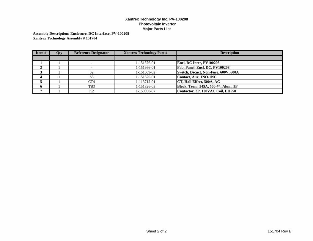
Xantrex Technology Inc. PV-100208 Photovoltaic Inverter
Major Parts ListAssembly Description: Enclosure, DC Interface, PV-100208Xantrex Technology Assembly # 151704
Item # Qty Reference Designator Xantrex Technology Part # Description
1 1 - 1-151576-01 Encl, DC Inter, PV1002082 1 - 1-151666-01 Fab, Panel, Encl, DC, PV1002083 1 S2 1-151669-02 Switch, Dscnct, Non-Fuse, 600V, 600A4 1 S5 1-151670-01 Contact, Aux, 1NO-1NC5 1 CT4 1-113712-01 CT, Hall Effect, 500A, AC6 1 TB3 1-151826-03 Block, Term, 545A, 500-#4, Alum, 3P7 1 K2 1-150060-07 Contactor, 3P, 120VAC Coil, EH550
Sheet 2 of 2 151704 Rev B