Embed Size (px)
Citation preview

FOR OWNERS OF MODEL 110BST


3
PRODUCT WARRANTY R E G I S T R A T I O N F O R M WARRANTY REGISTRATION This form must be �lled out by the dealer and signed by both the dealer and the customer at the time of delivery. Please mail or fax the completed form for validation of the equipment registration.
Customer’s Name__________________________________________________
Address _________________________________________________________
City, State, Postal Code_________________________, _______, ___________
Phone Number (_______) _______- ___________
PRODUCT INFORMATION
Tender Model # ___________ # rebmuN laireS _______________________
DEALER INSPECTION REPORT
____Tender frame secured to trailer
____Check fuel level and gas shut-o�
____Check engine oil level
____Start Honda engine
____Brake and lighting harness connection
____Remote throttle control functions
____Check reduction case oil level
____Lubricate unit where necessary
____Check air pressure in tires
____Electric brakes in working condition
____All guards/shields installed correctly
____All safety signs installed and intact
____Re�ectors and lights clean and working
____Review safety and operating instructions
____Inspect customer’s hitch for 2-5/16”
ball/gooseneck hitch
____Verify receipt of all options ordered
I have thoroughly instructed the buyer on the above-described equipment, including review of the Operator’s
Manual content, equipment care, adjustments, operational use, safety procedures, and applicable warranty
policy.
Dealer/Company Name____________________________________
City, State, Postal Code _________________________, _________, ______________
Dealer’s Signature______________________________________ Date ____/____/______
The above equipment and Operator’s Manual have been received by me, and I have been thoroughly instructed as
to care, adjustments, safe operation, and applicable warranty policy.
Owner’s Signature_____________________________________ Date ____/____/_______ 2902 Expansion Blvd. Storm Lake, Iowa 50588 Phone: 800-437-2334 Fax: 712-732-1028 Email: [email protected]
Cut
Her
e to
Rem
ove
Pag
e


5
Cut
Her
e to
Rem
ove
Pag
e

7
IMPORTANT INFORMATION
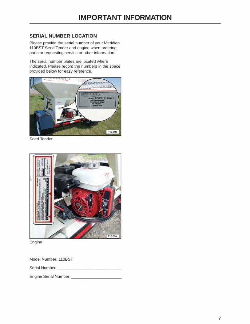
SERIAL NUMBER LOCATIONPlease provide the serial number of your Meridian 110BST Seed Tender and engine when ordering parts or requesting service or other information.
The serial number plates are located where indicated. Please record the numbers in the space provided below for easy reference.
Seed Tender
Engine
Model Number: 110BST
Serial Number: ____________________________
Engine Serial Number: ______________________

8
CONTENTS
1. INTRODUCTION . . . . . . . . . . . . . . . . . . . . . . . . . . . . . . . . . . . . . . . . . . . . . . . . . . . . . . . . . . 111.1 Congratulations . . . . . . . . . . . . . . . . . . . . . . . . . . . . . . . . . . . . 111.2 Operator Orientation . . . . . . . . . . . . . . . . . . . . . . . . . . . . . . . . . . 111.3 Owner/Operator . . . . . . . . . . . . . . . . . . . . . . . . . . . . . . . . . . . . 11
2. SAFETY. . . . . . . . . . . . . . . . . . . . . . . . . . . . . . . . . . . . . . . . . . . . . . . . . . . . . . . . . . . . . . . . . 122.1 General Safety . . . . . . . . . . . . . . . . . . . . . . . . . . . . . . . . . . . . . 132.2 Equipment Safety Guidelines . . . . . . . . . . . . . . . . . . . . . . . . . . . . . 142.3 Safety Training . . . . . . . . . . . . . . . . . . . . . . . . . . . . . . . . . . . . . 142.4 Safety Signs . . . . . . . . . . . . . . . . . . . . . . . . . . . . . . . . . . . . . . 152.5 Preparation. . . . . . . . . . . . . . . . . . . . . . . . . . . . . . . . . . . . . . . 152.6 Operating Safety . . . . . . . . . . . . . . . . . . . . . . . . . . . . . . . . . . . . 152.7 Maintenance Safety . . . . . . . . . . . . . . . . . . . . . . . . . . . . . . . . . . 152.8 Lock-Out or Tag-Out Safety . . . . . . . . . . . . . . . . . . . . . . . . . . . . . . 152.9 Storage Safety . . . . . . . . . . . . . . . . . . . . . . . . . . . . . . . . . . . . . 152.10 Transport Safety . . . . . . . . . . . . . . . . . . . . . . . . . . . . . . . . . . . 152.11 Refuelling Safety . . . . . . . . . . . . . . . . . . . . . . . . . . . . . . . . . . . 152.12 Battery Safety. . . . . . . . . . . . . . . . . . . . . . . . . . . . . . . . . . . . . 152.13 Sign-Off Form. . . . . . . . . . . . . . . . . . . . . . . . . . . . . . . . . . . . . 16
3. SAFETY SIGN LOCATIONS . . . . . . . . . . . . . . . . . . . . . . . . . . . . . . . . . . . . . . . . . . . . . . . . . 173.1 General Information . . . . . . . . . . . . . . . . . . . . . . . . . . . . . . . . . . . 173.2 How to Install Safety Signs. . . . . . . . . . . . . . . . . . . . . . . . . . . . . . . 173.3 Decal Locatioins . . . . . . . . . . . . . . . . . . . . . . . . . . . . . . . . . . . 17
4. SPECIFICATIONS. . . . . . . . . . . . . . . . . . . . . . . . . . . . . . . . . . . . . . . . . . . . . . . . . . . . . . . . . 20�4.1� �Overall�Specifications . . . . . . . . . . . . . . . . . . . . . . . . . . . . . . . . . 204.2� Bolt�Specifications . . . . . . . . . . . . . . . . . . . . . . . . . . . . . . . . . . . 20
4.2.1 Bolt Torque Values . . . . . . . . . . . . . . . . . . . . . . . . . . . . . . . 204.2.2 Grade Markings Chart . . . . . . . . . . . . . . . . . . . . . . . . . . . . . 20
5. MACHINE COMPONENTS AND CONTROLS . . . . . . . . . . . . . . . . . . . . . . . . . . . . . . . . . . . 215.1 Component Nomenclature and Location. . . . . . . . . . . . . . . . . . . . . . . . 215.2 Engine and Controls . . . . . . . . . . . . . . . . . . . . . . . . . . . . . . . . . . 225.3 Engine Warning Decals . . . . . . . . . . . . . . . . . . . . . . . . . . . . . . . . 23
6. PRE-OPERATING INSTRUCTIONS . . . . . . . . . . . . . . . . . . . . . . . . . . . . . . . . . . . . . . . . . . . 246.1 Safety . . . . . . . . . . . . . . . . . . . . . . . . . . . . . . . . . . . . . . . . . 246.2 Machine Break-In Period. . . . . . . . . . . . . . . . . . . . . . . . . . . . . . . . 24
6.2.1 Before Starting . . . . . . . . . . . . . . . . . . . . . . . . . . . . . . . . . 246.2.2 Inspections for 1/2, 5, and 10 Hours . . . . . . . . . . . . . . . . . . . . . . 24
6.3 Daily Pre-Operation Checklist . . . . . . . . . . . . . . . . . . . . . . . . . . . . . 24
7. TOWING . . . . . . . . . . . . . . . . . . . . . . . . . . . . . . . . . . . . . . . . . . . . . . . . . . . . . . . . . . . . . . . . 267.1 Transport Safety . . . . . . . . . . . . . . . . . . . . . . . . . . . . . . . . . . . . 267.2 Connecting the Trailer . . . . . . . . . . . . . . . . . . . . . . . . . . . . . . . . . 26
8. OPERATION . . . . . . . . . . . . . . . . . . . . . . . . . . . . . . . . . . . . . . . . . . . . . . . . . . . . . . . . . . . . . 288.1 Operating Safety . . . . . . . . . . . . . . . . . . . . . . . . . . . . . . . . . . . . 288.2 Opening and Closing Bin Cover . . . . . . . . . . . . . . . . . . . . . . . . . . . . 288.3 Operation. . . . . . . . . . . . . . . . . . . . . . . . . . . . . . . . . . . . . . . . 29
8.3.1 Loading (Filling Seed Tender). . . . . . . . . . . . . . . . . . . . . . . . . . 298.3.2 Unloading Seed Tender . . . . . . . . . . . . . . . . . . . . . . . . . . . . . 30
8.3.3 Unplugging Auger Tube . . . . . . . . . . . . . . . . . . . . . . . . . . . . . . . . 34

9
9. STORAGE . . . . . . . . . . . . . . . . . . . . . . . . . . . . . . . . . . . . . . . . . . . . . . . . . . . . . . . . . . . . . . . 359.1 Storage Safety . . . . . . . . . . . . . . . . . . . . . . . . . . . . . . . . . . . . . 359.2 General Information . . . . . . . . . . . . . . . . . . . . . . . . . . . . . . . . . . 359.3 Placing in Storage . . . . . . . . . . . . . . . . . . . . . . . . . . . . . . . . . . . 359.4 Removing from Storage . . . . . . . . . . . . . . . . . . . . . . . . . . . . . . . . 35
10. MAINTENANCE . . . . . . . . . . . . . . . . . . . . . . . . . . . . . . . . . . . . . . . . . . . . . . . . . . . . . . . . . 3610.1 Safety . . . . . . . . . . . . . . . . . . . . . . . . . . . . . . . . . . . . . . . . . 36
10.1.1 General Safety . . . . . . . . . . . . . . . . . . . . . . . . . . . . . . . . 3610.1.2 Lock-Out or Tag-Out Safety . . . . . . . . . . . . . . . . . . . . . . . . . 36
10.2 Lubrication . . . . . . . . . . . . . . . . . . . . . . . . . . . . . . . . . . . . . . 3710.2.1 Wheel Bearings . . . . . . . . . . . . . . . . . . . . . . . . . . . . . . . 3710.2.2 Auger Tube Pivot Shaft . . . . . . . . . . . . . . . . . . . . . . . . . . . . 3710.2.3 Seed Bin Cover. . . . . . . . . . . . . . . . . . . . . . . . . . . . . . . . 37
10.3 Battery . . . . . . . . . . . . . . . . . . . . . . . . . . . . . . . . . . . . . . . . 3810.3.1 Battery Safety . . . . . . . . . . . . . . . . . . . . . . . . . . . . . . . . 3810.3.2 Battery Replacement and Maintenance Tips . . . . . . . . . . . . . . . . . 3810.3.3 Battery Maintenance. . . . . . . . . . . . . . . . . . . . . . . . . . . . . . 38
10.4 Engine . . . . . . . . . . . . . . . . . . . . . . . . . . . . . . . . . . . . . . . . 3910.4.1 Refuelling Safety . . . . . . . . . . . . . . . . . . . . . . . . . . . . . . . 3910.4.2 Approved Fuel . . . . . . . . . . . . . . . . . . . . . . . . . . . . . . . . . 3910.4.3 Engine Oil . . . . . . . . . . . . . . . . . . . . . . . . . . . . . . . . . . . 3910.4.4 Change Engine and Reduction Case Oil . . . . . . . . . . . . . . . . . . . 3910.4.5 Clean Air Cleaner . . . . . . . . . . . . . . . . . . . . . . . . . . . . . . . 4010.4.6 Engine Circuit Protection . . . . . . . . . . . . . . . . . . . . . . . . . . . 40
10.5 Engine Actuator Replacement . . . . . . . . . . . . . . . . . . . . . . . . . . . . 4010.5.1 Actuator Removal . . . . . . . . . . . . . . . . . . . . . . . . . . . . . . . 4010.5.2 Actuator Installation . . . . . . . . . . . . . . . . . . . . . . . . . . . . . . 41
10.6 Unplugging Auger Delivery Tube . . . . . . . . . . . . . . . . . . . . . . . . . . . 4210.7 Auger Drive Belt . . . . . . . . . . . . . . . . . . . . . . . . . . . . . . . . . . . 43
10.7.1 Drive Belt Tension . . . . . . . . . . . . . . . . . . . . . . . . . . . . . . 4310.7.2 Drive Belt Installation . . . . . . . . . . . . . . . . . . . . . . . . . . . . 43
10.8 Engine Speed Setting. . . . . . . . . . . . . . . . . . . . . . . . . . . . . . . . . 4310.9 Trailer Break-Away System . . . . . . . . . . . . . . . . . . . . . . . . . . . . . . 44
10.9.1 Testing the Battery. . . . . . . . . . . . . . . . . . . . . . . . . . . . . . 4410.9.2 Changing Battery . . . . . . . . . . . . . . . . . . . . . . . . . . . . . . 4410.9.3 Replacing Battery . . . . . . . . . . . . . . . . . . . . . . . . . . . . . . 45
10.10 Wheel Bolt Torque Requirements . . . . . . . . . . . . . . . . . . . . . . . . . . 4510.11 Axle Bolts and Frame Hold-Down Bolts . . . . . . . . . . . . . . . . . . . . . . . 4510.12 Service Record Chart . . . . . . . . . . . . . . . . . . . . . . . . . . . . . . . . 4610.13 Service Checks . . . . . . . . . . . . . . . . . . . . . . . . . . . . . . . . . . . 47
10.13.1 Daily (8 Hours) . . . . . . . . . . . . . . . . . . . . . . . . . . . . . . . 4710.13.2 Weekly (50 Hours) . . . . . . . . . . . . . . . . . . . . . . . . . . . . . 4710.13.3 Annually (400 Hours). . . . . . . . . . . . . . . . . . . . . . . . . . . . 47
10.14 Axle Maintenance . . . . . . . . . . . . . . . . . . . . . . . . . . . . . . . . . . 4710.14.1 First 200 Miles . . . . . . . . . . . . . . . . . . . . . . . . . . . . . . . 4710.14.2 3,000 Miles or 3 Months . . . . . . . . . . . . . . . . . . . . . . . . . . 4710.14.3 6,000 Miles or 6 Months . . . . . . . . . . . . . . . . . . . . . . . . . . 4810.14.4 12,000 Miles or 12 Months. . . . . . . . . . . . . . . . . . . . . . . . . 48
10.15 Tires . . . . . . . . . . . . . . . . . . . . . . . . . . . . . . . . . . . . . . . . . 4810.16 Welding Repairs . . . . . . . . . . . . . . . . . . . . . . . . . . . . . . . . . . . 48

10
11. OEM LITERATURE . . . . . . . . . . . . . . . . . . . . . . . . . . . . . . . . . . . . . . . . . . . . . . . . . . . . . . . 4911.1 Honda® Engine . . . . . . . . . . . . . . . . . . . . . . . . . . . . . . . . . . . 4911.2 Axle . . . . . . . . . . . . . . . . . . . . . . . . . . . . . . . . . . . . . . . . . 49
12. TROUBLESHOOTING . . . . . . . . . . . . . . . . . . . . . . . . . . . . . . . . . . . . . . . . . . . . . . . . . . . . 5012.1 Troubleshooting Chart . . . . . . . . . . . . . . . . . . . . . . . . . . . . . . . 50
13. WARRANTY . . . . . . . . . . . . . . . . . . . . . . . . . . . . . . . . . . . . . . . . . . . . . . . . . . . . . . . . . . . . 5113.1 Warranty Statement . . . . . . . . . . . . . . . . . . . . . . . . . . . . . . . . . 51
14. PARTS. . . . . . . . . . . . . . . . . . . . . . . . . . . . . . . . . . . . . . . . . . . . . . . . . . . . . . . . . . . . . . . . . 5214.1 110BST Seed Tender . . . . . . . . . . . . . . . . . . . . . . . . . . . . . . . . 5314.2 110BST Seed Tender Frame . . . . . . . . . . . . . . . . . . . . . . . . . . . . 5414.3 110BST Engine and Actuator . . . . . . . . . . . . . . . . . . . . . . . . . . . . 5614.4 110BST Upper Auger Tube . . . . . . . . . . . . . . . . . . . . . . . . . . . . . 5714.5 110BST Lower Auger Tube . . . . . . . . . . . . . . . . . . . . . . . . . . . . . 5814.6 110BST Three Tier Spout . . . . . . . . . . . . . . . . . . . . . . . . . . . . . . 5914.7 110BST Trailer . . . . . . . . . . . . . . . . . . . . . . . . . . . . . . . . . . . 60
11
1. INTRODUCTION
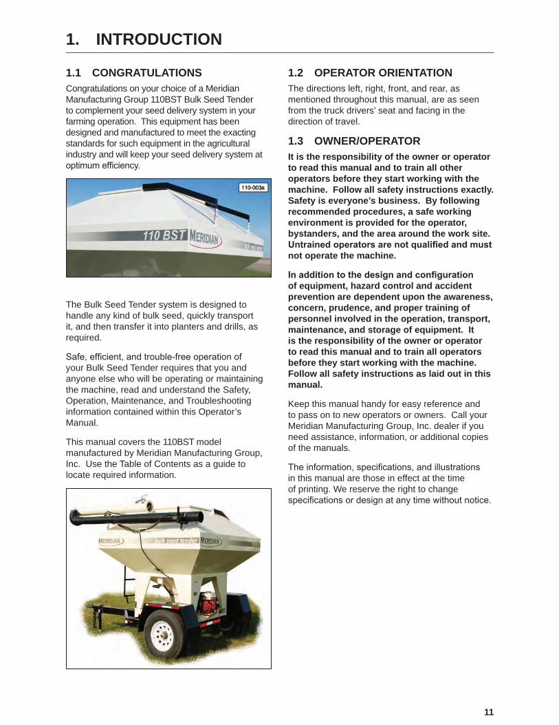
1.1 CONGRATULATIONSCongratulations on your choice of a Meridian Manufacturing Group 110BST Bulk Seed Tender to complement your seed delivery system in your farming operation. This equipment has been designed and manufactured to meet the exacting standards for such equipment in the agricultural industry and will keep your seed delivery system at optimum�efficiency.
The Bulk Seed Tender system is designed to handle any kind of bulk seed, quickly transport it, and then transfer it into planters and drills, as required.
Safe,�efficient,�and�trouble‑free�operation�of�your Bulk Seed Tender requires that you and anyone else who will be operating or maintaining the machine, read and understand the Safety, Operation, Maintenance, and Troubleshooting information contained within this Operator’s Manual.
This manual covers the 110BST model manufactured by Meridian Manufacturing Group, Inc. Use the Table of Contents as a guide to locate required information.
1.2 OPERATOR ORIENTATIONThe directions left, right, front, and rear, as mentioned throughout this manual, are as seen from the truck drivers’ seat and facing in the direction of travel.
1.3 OWNER/OPERATORIt is the responsibility of the owner or operator to read this manual and to train all other operators before they start working with the machine. Follow all safety instructions exactly. Safety is everyone’s business. By following recommended procedures, a safe working environment is provided for the operator, bystanders, and the area around the work site. Untrained operators are not qualified and must not operate the machine.
In addition to the design and configuration of equipment, hazard control and accident prevention are dependent upon the awareness, concern, prudence, and proper training of personnel involved in the operation, transport, maintenance, and storage of equipment. It is the responsibility of the owner or operator to read this manual and to train all operators before they start working with the machine. Follow all safety instructions as laid out in this manual.
Keep this manual handy for easy reference and to pass on to new operators or owners. Call your Meridian Manufacturing Group, Inc. dealer if you need assistance, information, or additional copies of the manuals.
The�information,�specifications,�and�illustrations�in this manual are those in effect at the time of printing. We reserve the right to change specifications�or�design�at�any�time�without�notice.

12
2. SAFETY
The�Safety�Alert�symbol�identifies�important�safety�messages�on�the�Meridian�Bulk�Seed�Tender�Models�and in the manual. When you see this symbol, be alert to the possibility of personal injury or death. Follow the instructions in the safety message.
If you have any questions not answered in this manual, require additional copies of the manual, or the manual is damaged, please contact your dealer or Meridian Manufacturing Group, 2902 Expansion Blvd., Storm Lake, Iowa, 50588, toll free 1-800-437-2334, phone (712) 732-1780, or fax (712) 732-1028.
SIGNAL WORDS:Note the use of the signal words DANGER, WARNING, and CAUTION with the safety messages. The appropriate signal word for each message has been selected using the following guidelines:
SAFETY ALERT SYMBOL
This Safety Alert symbol means ATTENTION! BECOME ALERT! YOUR SAFETY IS INVOLVED!
WHY IS SAFETY IMPORTANT TO YOU?3 Big Reasons
• Accidents Disable and Kill • • Accidents Cost •
• Accidents Can Be Avoided •
DANGER - Indicates an imminently hazardous situation that, if not avoided, will result in death or serious injury. This signal word is to be limited to the most extreme situations typically for machine components which, for functional purposes, cannot be guarded.
WARNING - Indicates a potentially hazardous situation that, if not avoided, could result in death or serious injury, and includes hazards that are exposed when guards are removed. It may also be used to alert against unsafe practices.
CAUTION - Indicates a potentially hazardous situation that, if not avoided, may result in minor or moderate injury. It may also be used to alert against unsafe practices.

13
YOU are responsible for the SAFE operation and maintenance of your Meridian Manufacturing Group Bulk Seed Tender. YOU must ensure that you and anyone else who is going to operate, maintain, or work around the Bulk Seed Tender be familiar with the operating and maintenance procedures and related SAFETY information contained in this manual. This manual will take you step-by-step through your working day and alert you to all good safety practices that should be adhered to while operating the Bulk Seed Tender system.
Remember, YOU are the key to safety. Good safety practices not only protect you but also the people around you. Make these practices a working part of your safety program. Be certain that EVERYONE operating this equipment is familiar with the recommended operating and maintenance procedures and follow all the safety precautions. Most accidents can be prevented. Do not risk injury or death by ignoring good safety practices.
• Bulk Seed Tender system owners must give operating instructions to operators or employees before allowing them to operate the machine, and then annually thereafter per OSHA (Occupational Safety and Health Administration) regulation 1928.57.
• The most important safety feature on this equipment is a SAFE operator. It is the operator’s responsibility to read and follow ALL Safety and Operating instructions in the manual. Most accidents can be avoided.
• A person who has not read and understood all operating and safety instructions is not qualified�to�operate�the�machine.�An�untrained�operator exposes himself and bystanders to possible serious injury or death. Always be and stay alert to any possible unsafe operating or maintenance procedures or conditions.
• Do not modify the equipment in any way. Unauthorized�modification�may�impair�the�function and/or safety of the components and systems and could affect the life of the equipment, possibly invalidating the warranty coverage.
• Think SAFETY! Work SAFELY!
2.1 GENERAL SAFETY1. Read and understand the Operator’s
Manual and all safety signs before operating,�maintaining,�adjusting,�filling,�unloading, or unplugging the Bulk Seed Tender system.
2. � �Have�a�first�aid�kit�available�for�use�should the need arise and know how to use it.
3. � �Have�a�fire�extinguisher�available�for�use should the need arise and know how to use it.
4. Do not allow riders.
5. When working around or operating this equipment, wear appropriate personal protective equipment. This list includes but is not limited to:
• A hard hat• Protective shoes with slip resistant soles• Protective goggles, glasses, or face shield • Heavy gloves and protective clothing• Respirator
6. � �Do�not�allow�long�hair,�loose�fitting�clothing, or jewelry around equipment.
7. Install and secure all guards before starting.
8. STOP
Stop engine, remove ignition key, and wait for all moving parts to stop before servicing, repairing, adjusting, loading, filling,�or�unplugging.
9. do not
operatesigned by
date
WARNING
Establish a lock-out or tag-out policy for the work site. Be sure all personnel are trained in and follow all procedures. Lock-out or tag-out all power sources before working around loading/unloading equipment.
10. Clear the area of people, especially small children, before starting.
11. Review safety related items annually with all personnel who will be operating, using, or maintaining the Bulk Seed Tender system.
14
2.2 EQUIPMENT SAFETY GUIDELINES
1. Safety of the operator and bystanders is one of the main concerns in designing and developing a machine. However, every year many accidents occur which could have been avoided by a few seconds of thought and a more careful approach to handling equipment. You, the operator, can avoid many accidents by observing the following precautions in this section. To avoid personal injury or death, study the following precautions and insist those working with you, or for you, follow them.
2. In order to provide a better view, certain photographs or illustrations in this manual may show an assembly with a safety shield removed. However, equipment should never be operated in this condition. Keep all shields in place. If shield removal becomes necessary for repairs, replace the shield prior to use.
3. Never use alcoholic beverages or sedative drugs while operating this equipment. Consult your doctor about operating this machine while taking prescription medications.
4. Do not allow persons to operate or assemble this unit until they have read this manual and have developed a thorough understanding of the safety precautions and how it works. Review the safety instructions with all users annually.
5. Under no circumstances should young children be allowed to work with this equipment. This equipment is dangerous to children and persons unfamiliar with its operation. The operator should be a responsible, properly trained, and physically able person familiar with farm machinery and trained in this equipment’s operations. If the elderly are assisting with farm work, their physical limitations need to be recognized and accommodated.
6. Never exceed the limits of a piece of machinery. If its ability to do a job, or to do so safely, is in question - DON’T TRY IT.
7. Do not modify the equipment in any way. Unauthorized�modification�may�result�in�serious injury or death and may impair the function and life of the equipment.
8. In�addition�to�the�design�and�configuration�of this implement, including Safety Signs and Safety Equipment, hazard control and accident prevention are dependent upon the awareness, concern, prudence, and proper training of personnel involved in the operation, transport, maintenance, and storage of the machine. Refer to Safety Messages and operation instruction in each of the appropriate sections of the auxiliary equipment and machine Manuals. Note all Safety Signs affixed�to�the�auxiliary�equipment.
2.3 SAFETY TRAINING1. Safety is a primary concern in the design and
manufacture of our products. Unfortunately, our efforts to provide safe equipment can be wiped out by a single careless act of an operator or bystander.
2. In�addition�to�the�design�and�configuration�of equipment, hazard control and accident prevention are dependent upon the awareness, concern, prudence, and proper training of personnel involved in the operation, transport, maintenance, and storage of this equipment.
3. The best safety feature is an informed, careful operator. It is the operator’s responsibility to read and comply with ALL Safety and Operating instructions in the manual. Accidents can be avoided.
4. Working with unfamiliar equipment can lead to injuries. Read this manual, as well as the manual for your auxiliary equipment, before assembling or operating to acquaint yourself with the machines. If this machine is used by any person other than yourself, it is your responsibility to make certain that the operator reads and understands the operator’s manuals and is instructed in safe and proper use.
5. Know your controls and how to immediately stop augers, conveyors, and any other auxiliary equipment in an emergency. Read this manual and the one provided with all auxiliary equipment.
6. Train all new personnel and review instructions frequently with employees. Be certain only a properly trained and physically able person will operate the machinery. A person who has not read and understood all operating and safety�instructions�is�not�qualified�to�operate�the machine. An untrained operator exposes himself and bystanders to possible serious injury or death.

15
2.4 SAFETY SIGNS Refer to the Safety Signs section for safety information.
2.5 PREPARATIONRefer to the Preparation section for safety information.
2.6 OPERATING SAFETYRefer to the Operating section for safety information.
2.7 MAINTENANCE SAFETYRefer to the Maintenance section for safety information.
2.8 LOCK-OUT OR TAG-OUT SAFETYRefer to the Maintenance section for safety information.
2.9 STORAGE SAFETYRefer to the Storage section for safety information.
2.10 TRANSPORT SAFETYRefer to the Towing section for safety information.
2.11 REFUELLING SAFETYRefer to the Engine section for safety information.
2.12 BATTERY SAFETYRefer to the Battery section for safety information.

16
2.13 SIGN-OFF FORMMeridian Manufacturing Group follows the general Safety�Standards�specified�by�the�American�Society of Agricultural Engineers (ASAE) and Occupational Safety and Health Administration (OSHA). Anyone who will be operating and/or maintaining the Meridian Manufacturing Group Bulk Seed Tender must read and clearly understand ALL Safety, Operating, and Maintenance information presented in this manual.
Do not allow anyone to operate this equipment until such information has been reviewed. Annually review this information before the season start-up.
SIGN-OFF FORMDate Employee’s Signature Employer’s Signature
Make these periodic reviews of SAFETY and OPERATION a standard practice for all of your equipment. We feel an untrained operator is unqualified�to�operate�this�machine.
A sign-off sheet is provided for your recordkeeping to show that all personnel who will be working with the equipment have read and understand the information in the Operator’s Manual and have been instructed in the operation of the equipment.

17
3. SAFETY SIGN LOCATIONS
3.1 GENERAL INFORMATIONThe types of safety signs and locations on the equipment are shown in the following pages. Good SAFETY AWARENESS requires that you familiarize yourself with the various safety signs, the type of warning and the area, or a particular function related to that area.
1. N INGAR
If safety signs have been damaged, removed, become illegible, or parts replaced without signs, new signs must be applied.
2. Replacement parts that displayed a safety sign should also display the current sign.
3. Replacement safety signs (labels) are available from your authorized Dealer Parts Department or the factory at no cost.
3.2 HOW TO INSTALL SAFETY SIGNS1. Be sure that the installation area is clean and
dry.
2. Be sure temperature is above 50°F (10°C).
3. Determine exact position before you remove the backing paper.
4. Remove the smallest portion of the split backing paper.
5. Align�the�sign�over�the�specified�area�and�carefully press the small portion with the exposed sticky backing in place.
6. Slowly peel back the remaining paper and carefully smooth the remaining portion of the sign in place.
7. Small air pockets can be pierced with a pin and smoothed out using a piece of sign backing paper.
3.3 DECAL LOCATIONS
1. NOTICE — Product Warranty (#18432)
2. Product Serial Number Decal (#19984)
Storm Lake, IA 50588
6720110948768

18
3. CAUTION — Read and Understand (#19934) 4. WARNING — Falling Hazard (#19939)
5. WARNING — Entanglement Hazard (#19936)
19
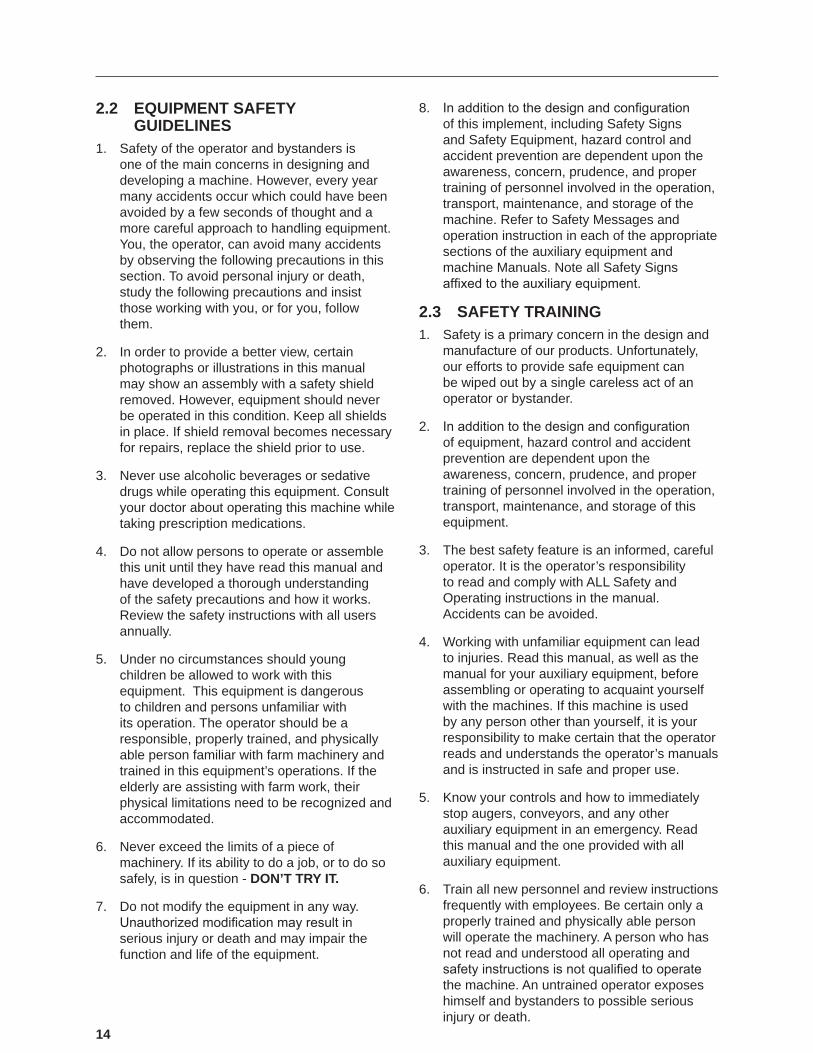
6. WARNING — Entanglement Hazard (#19937)
7. DANGER — Rotating Part Hazard (#18435)
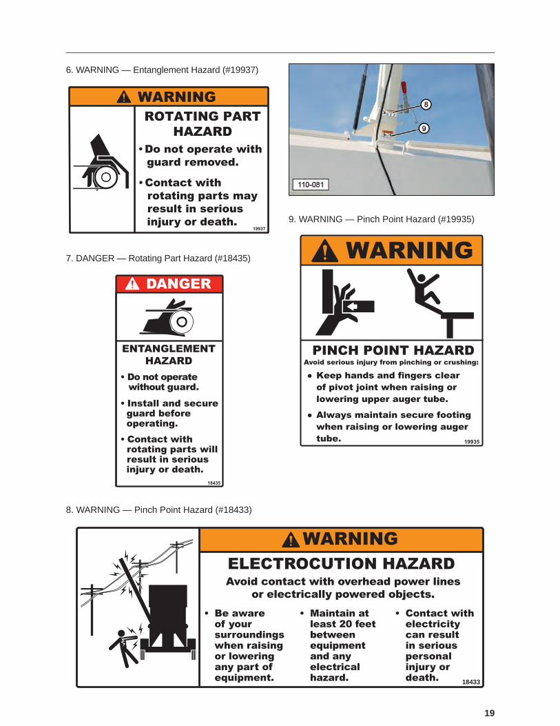
8. WARNING — Pinch Point Hazard (#18433)
18433
9. WARNING — Pinch Point Hazard (#19935)
20
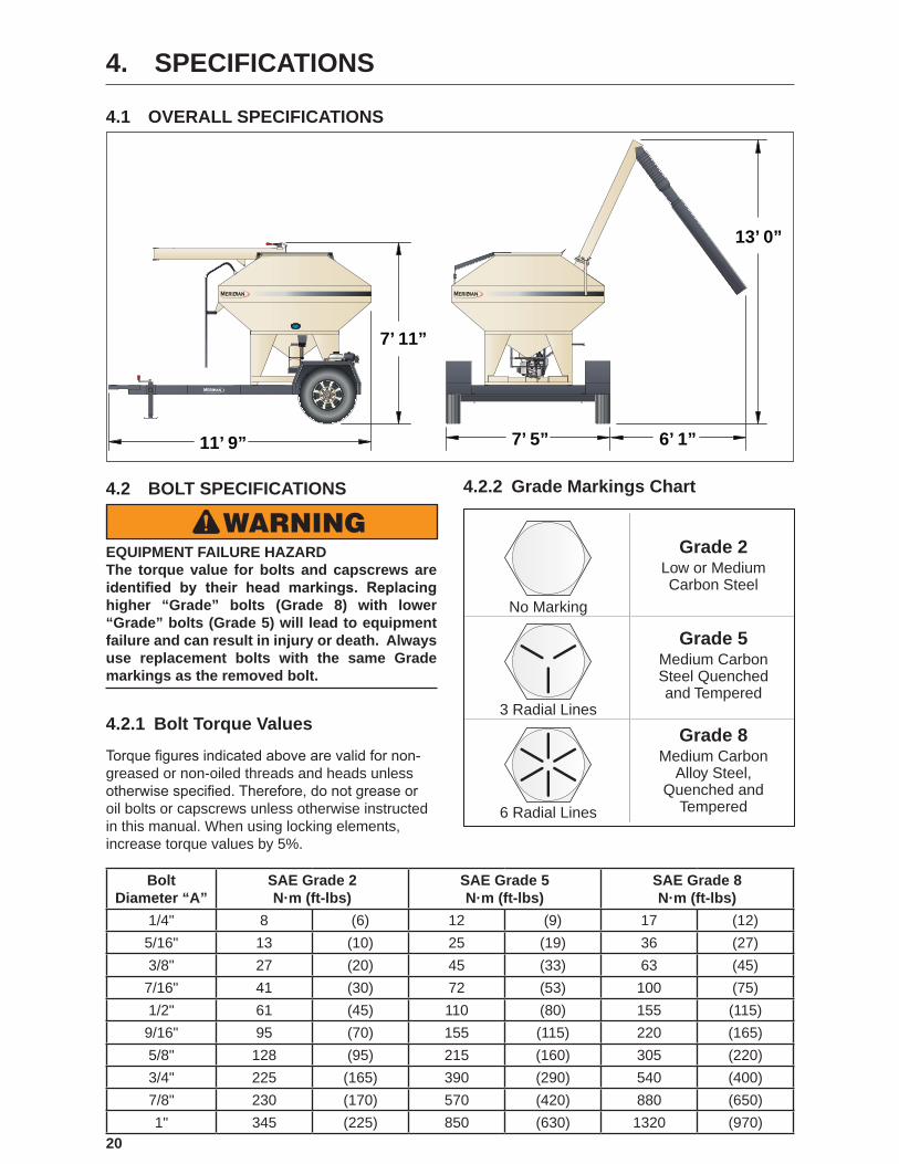
4. SPECIFICATIONS
4.1 OVERALL SPECIFICATIONS
13’ 0”
7’ 11”
11’ 9” 7’ 5” 6’ 1”
4.2 BOLT SPECIFICATIONS
WARNINGEQUIPMENT FAILURE HAZARD The torque value for bolts and capscrews are identified by their head markings. Replacing higher “Grade” bolts (Grade 8) with lower “Grade” bolts (Grade 5) will lead to equipment failure and can result in injury or death. Always use replacement bolts with the same Grade markings as the removed bolt.
4.2.1 Bolt Torque Values
Torque�figures�indicated�above�are�valid�for�non‑greased or non-oiled threads and heads unless otherwise�specified.�Therefore,�do�not�grease�or�oil bolts or capscrews unless otherwise instructed in this manual. When using locking elements, increase torque values by 5%.
BoltDiameter “A”
SAE Grade 2N·m (ft-lbs)
SAE Grade 5N·m (ft-lbs)
SAE Grade 8N·m (ft-lbs)
1/4" 8 (6) 12 (9) 17 (12)5/16" 13 (10) 25 (19) 36 (27)3/8" 27 (20) 45 (33) 63 (45)7/16" 41 (30) 72 (53) 100 (75)1/2" 61 (45) 110 (80) 155 (115)9/16" 95 (70) 155 (115) 220 (165)5/8" 128 (95) 215 (160) 305 (220)3/4" 225 (165) 390 (290) 540 (400)7/8" 230 (170) 570 (420) 880 (650)1" 345 (225) 850 (630) 1320 (970)
4.2.2 Grade Markings Chart
No Marking
Grade 2Low or MediumCarbon Steel
Grade 5Medium CarbonSteel Quenchedand Tempered
Grade 8Medium Carbon
Alloy Steel,Quenched and
Tempered
3 Radial Lines
6 Radial Lines

21
5. MACHINE COMPONENTS AND CONTROLS
5.1 COMPONENT NOMENCLATURE AND LOCATION
The Meridian seed tender is designed as a bulk seed transfer unit to transport large amounts of seed into a planter or drill.
Bulk seed can be loaded into the single, seed compartment from a variety of sources including seed boxes. The large seed bin cover (1) slides open on two slide rails to provide an adequate opening for loading the seed. Open the cover using ladder (16).
(1) Seed Bin Cover. (2) Seed Bin Cover Rails. (3) Seed Tender Frame. (4) Trailer. (5) Gasoline Engine.
(6) Trailer Safety Chains. (7) Jack Stand. (8) Break-Away Trailer Brake System. (9) Document Storage Tube (inside of frame). (10) Delivery Spout Storage Bracket. (11) Slide Gate Lever. (12) View Glass. (13) Auger/Engine Throttle Switch. (14) Delivery Spout. (15) Auger Tube. (16) Ladder.
Once�the�unit�is�filled,�the�side�mounted�auger�transfers the seed through auger tube (15) and delivery spout (14) into planters or drills. Slide gate lever (11) on the seed compartment controls the flow�of�seed�into�the�auger.
(17) Remote Throttle Switch Auxiliary Plug. (18) Auger-Speed Actuator. (19) Gas Engine Controls. (20) Gas Engine On/Off Controls. (21) Air Filter.
Gas engine (5) mounted on the frame powers the auger drive pulley (22). A reduction case centrifugal clutch on the engine output shaft engages when the engine speed reaches 1400 RPM. The auger belt drive system (30) transmits power from the engine to the auger. Use auger throttle switch (13) to increase or decrease the speed of the auger.
The auger will only unload to the left side. A telescoping spout on the end of the auger allows for convenient distribution.
(22) Auger Drive Pulley. (23) Choke Lever. (24) Fuel Shut-Off Lever. (25) Throttle Lever (connected to auger speed actuator). (26) Battery Hold Down Strap (27) Battery. (28) Electrical System Fuse. (29) Auger-Speed Actuator. (30) Centrifugal Clutch Reduction Case. (31) Auger Belt Drive and Guard.
22
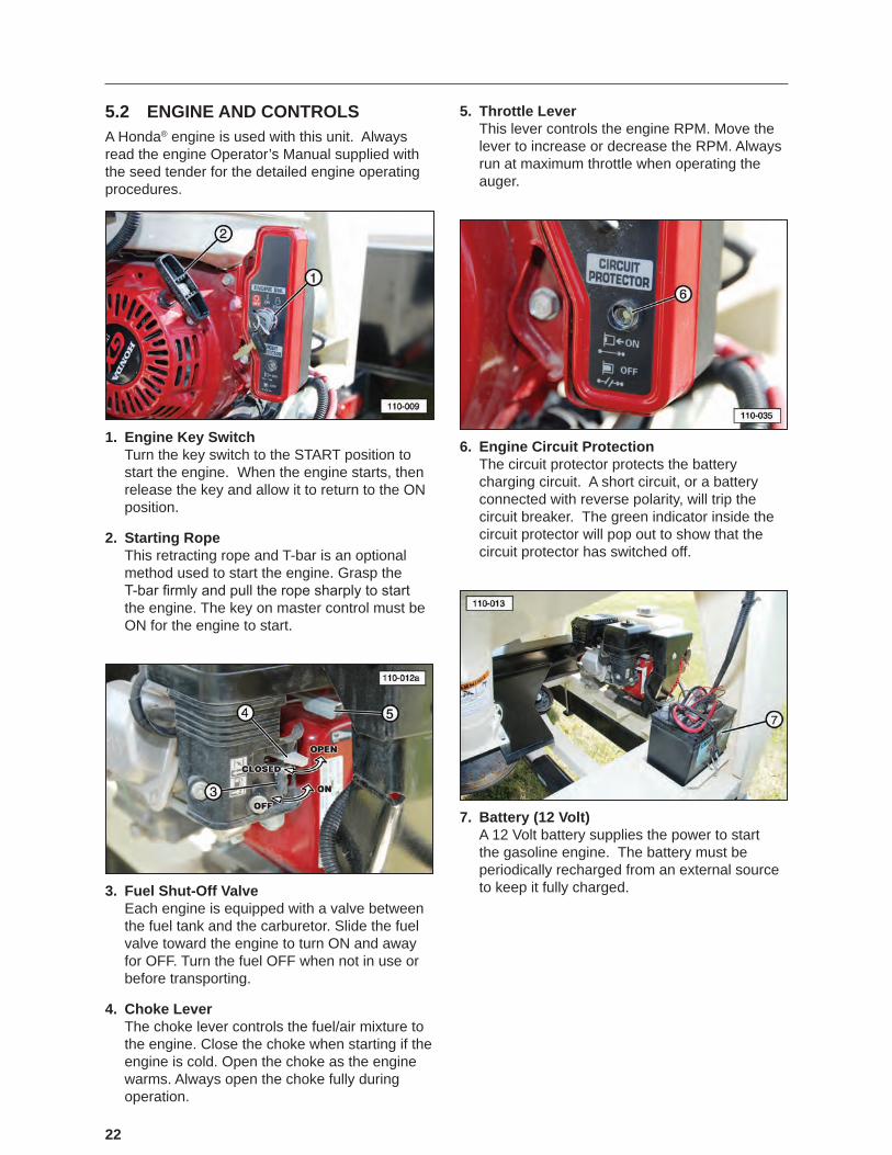
5.2 ENGINE AND CONTROLSA Honda® engine is used with this unit. Always read the engine Operator’s Manual supplied with the seed tender for the detailed engine operating procedures.
1. Engine Key Switch Turn the key switch to the START position to start the engine. When the engine starts, then release the key and allow it to return to the ON position.
2. Starting Rope This retracting rope and T-bar is an optional method used to start the engine. Grasp the T‑bar�firmly�and�pull�the�rope�sharply�to�start�the engine. The key on master control must be ON for the engine to start.
3. Fuel Shut-Off Valve Each engine is equipped with a valve between the fuel tank and the carburetor. Slide the fuel valve toward the engine to turn ON and away for OFF. Turn the fuel OFF when not in use or before transporting.
4. Choke Lever The choke lever controls the fuel/air mixture to the engine. Close the choke when starting if the engine is cold. Open the choke as the engine warms. Always open the choke fully during operation.
5. Throttle Lever This lever controls the engine RPM. Move the lever to increase or decrease the RPM. Always run at maximum throttle when operating the auger.
6. Engine Circuit Protection The circuit protector protects the battery charging circuit. A short circuit, or a battery connected with reverse polarity, will trip the circuit breaker. The green indicator inside the circuit protector will pop out to show that the circuit protector has switched off.
7. Battery (12 Volt) A 12 Volt battery supplies the power to start the gasoline engine. The battery must be periodically recharged from an external source to keep it fully charged.
23
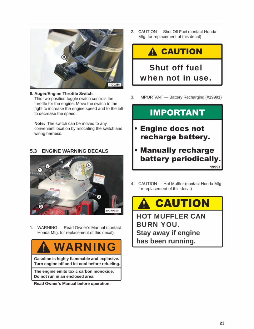
8. Auger/Engine Throttle Switch This two‑position toggle switch controls the throttle for the engine. Move the switch to the right to increase the engine speed and to the left to decrease the speed. Note: The switch can be moved to any convenient location by relocating the switch and wiring harness.
5.3 ENGINE WARNING DECALS
1. WARNING — Read Owner’s Manual (contact Honda Mfg. for replacement of this decal)
WARNINGGasoline is highly flammable and explosive.Turn engine off and let cool before refueling.
The engine emits toxic carbon monoxide.Do not run in an enclosed area.
Read Owner’s Manual before operation.
2. CAUTION — Shut Off Fuel (contact Honda Mfg. for replacement of this decal)
Shut off fuelwhen not in use.
3. IMPORTANT — Battery Recharging (#19991)
4. CAUTION�—�Hot�Muffler�(contact�Honda�Mfg.�for replacement of this decal)
HOT MUFFLER CANBURN YOU.Stay away if enginehas been running.

24
6. PRE-OPERATING INSTRUCTIONS
6.1 SAFETY1. Never operate the seed delivery
system and auxiliary equipment until you have read and completely understand this manual, the auxiliary equipment Operator’s Manual, and each of the Safety Messages found on the safety signs on the delivery system and auxiliary equipment.
2. PROLONGED EXPOSURE TO LOUD NOISE MAY CAUSE PERMANENT HEARING LOSS! Motors or equipment can be noisy enough to cause permanent or partial hearing loss. We recommend that you wear hearing protection on a full-time basis if the noise in the operator’s position exceeds 80db. NOTE: Hearing loss from loud noise (tractors, chain saws, radios, and other such sources close to the ear) is cumulative over a lifetime with uncertain natural recovery.
3. Clear working area of debris, trash, or hidden obstacles that might be hooked or snagged, causing injury, damage, or tripping.
4. Operate�only�in�daylight�or�good�artificial�light.
5. Be sure machine is properly attached to the trailer, adjusted, and in good operating condition.
6. Ensure that all guards, shielding, and safety signs are properly installed and in good condition.
7. Before starting, give the machine a “once over” for any loose bolts, worn parts, cracks, leaks, frayed belts, and make necessary repairs. Always follow maintenance instructions.
6.2 MACHINE BREAK-IN PERIODA special break-in procedure has been developed to ensure the integrity of the seed tender when first�put�into�service.��Follow�the�Before�Starting�instructions and then follow the Inspections for 1/2, 5, and 10 Hours instructions at the appropriate interval.
After completing these instructions, follow the normal service schedule in the Maintenance section and engine manual.
6.2.1 Before Starting
1. Read and follow the instructions in the Honda® engine and the Meridian Operator’s Manuals.
2. Review and follow the Pre-operation Checklist before starting machine.
3. Initially check wheel bolt torque and then again at 10, 25, and 50 miles. Refer to the Wheel Bolt Torque Requirements section in this manual for tightening instructions.
4. Start the engine and check the controls. Be sure that they function properly.
6.2.2 Inspections for 1/2, 5, and 10 Hours
1. Recheck�the�engine�and�reduction�case�fluid�levels.�Refill,�as�required.
2. Recheck the tension and alignment of the auger tube drive belt.
3. Recheck hardware and fasteners; frame to trailer tie-downs, all fasteners, and wheel bolts.�Tighten�to�their�specified�torque.
4. At 10 hours, change the engine oil with the specified�oil.
6.3 DAILY PRE-OPERATION CHECK-LISTEfficient�and�safe�operation�of�the�Meridian�Bulk�Seed Tender system requires that each operator reads and follows the operating procedures and all related safety precautions outlined in this section.
A preoperational checklist is provided for the operator. It is important for both personal safety and�maintaining�the�efficient�operation�of�the�delivery system that this checklist be followed.
Before operating the delivery system and each time thereafter, the following areas should be checked:
1. Lubricate the machine, as outlined and shown in the lubrication photos in the Maintenance section of this manual. Follow the prescribed schedule.
2. Check�the�engine�fluid�levels,�fuel,�and�reduction case oil level. Add, as required.
25
IMPORTANTThe engine warranty is void if the engine is run
without oil.
3. Check the oil level in the engine’s centrifugal clutch reduction case.
4. Check hardware and fasteners; seed tender frame to trailer tie-downs, hitch bolts, trailer hitch to trailer bolts, and all other fasteners. Tighten�to�their�specified�torque.
5. Make sure the wheel bolt lug nuts are tight.
6. Check the tires and ensure that they are inflated�to�their�specified�pressure.
7. Remove all entangled material.
8. Visually inspect the auger, auger tube, and delivery spout for damage.
9. Test the Break-Away brake unit and the trailer brakes.
a. Make sure the trailer brakes are operating properly.
b. Make sure the trip wire to the break-away switch is connected to the tow vehicle.
c. Make sure the pin is correctly installed in the break-away switch.
d. Press the Test button. The indicator should illuminate green. If the red light illuminates, the battery charge is low. Refer to the Break-Away System in the Maintenance section for instructions on charging the battery.
10. Check the tension of the auger drive belt. Follow the instructions in the manual to correct the tension and/or alignment.

26
7. TOWING
7.1 TRANSPORT SAFETY1. Comply with local, state, and federal
laws governing safety and conveyance of farm machinery on public roads.
2. Ensure�all�lights,�reflectors,�and�other�lighting�requirements are installed and in good working condition.
3. Ensure that the trailer is equipped with brakes that are in good working order. Be familiar with their operation.
4. Do not exceed a safe travel speed. Slow down for rough terrain and when cornering.
5. Fasten frame securely to trailer before transporting.
6. Be sure the trailer is securely hitched to the towing vehicle and a retainer is used through the hitch jaws. Always attach a safety chain between the hitch and the towing vehicle.
7. Stay away from overhead power lines. Electrocution can occur without direct contact.
8. Plan�your�route�to�avoid�heavy�traffic.
9. Install auger spout transport lock before transporting.
10. Do not drink and drive.
11. Be a safe and courteous driver. Yield to oncoming�traffic�in�all�situations,�including�narrow bridges, intersections, etc. Watch for�traffic�when�operating�near�or�crossing�roadways.
12. Never allow riders on the tender or the trailer.
7.2 CONNECTING THE TRAILER
WARNING UPENDING HAZARD To prevent serious injury or death from upending hazard, do not stand over hitch when unhooking the trailer from the tow vehicle.
1. Complete the Pre-operation Checklist.
WARNING CRUSH HAZARD Ensure that all bystanders, especially small children, are clear of the working area. Ensure there is enough room and clearance to safely back up to the machine.
2. Use the trailer jack to lift the hitch above the height of the receiver on the tow vehicle (standard hitch assembly shown).
3. Remove the retainer pin. Release or open the receiver by pulling the locking cover back, as shown.

27
4. Slowly back the tow vehicle until the hitch and ball are aligned.
5. Lower the hitch onto the ball.
6. Raise the jack and place it in its stowed position.
7. Close the receiver by pulling the spring loaded locking collar back to release the hitch mechanism. Install the retainer clip to prevent unwanted opening of the receiver.
8. Attach the safety chain securely to the tow vehicle to prevent unexpected separation. Cross the chains when attaching.
9. Connect the wiring harness for the lights and brakes.
10. Connect the break-away system cable to the tow vehicle. Make sure the key on the end of the cable is properly plugged into the receiving unit.
11. Route all the cables in a manner that will prevent snagging. Be sure to provide slack for turning.
28
8. OPERATION
8.1 OPERATING SAFETY1. Make sure that anyone who will be
operating the Bulk Seed Tender system or working on or around the unit reads and understands all the operating, maintenance, and safety information in the operator’s manual.
2. Keep all bystanders, especially children, away from the machine when loading or unloading, or when authorized personnel are carrying out maintenance work.
3. do not
operatesigned by
date
WARNING
Establish a lock-out or tag-out policy for the work site. Be sure all personnel are trained in and follow all procedures. Lock-out or tag-out all power sources before servicing the unit or working around loading/unloading equipment.
4. STOP
Stop engine, remove ignition key, and wait for all moving parts to stop before servicing, repairing, adjusting, loading, filling,�or�unplugging.
5. Keep working area clean and free of debris to prevent slipping or tripping.
6. Do not allow riders on the trailer or frame when transporting.
7. Keep hands, feet, hair, and clothing away from rotating parts.
8. � �Do�not�place�hands,�fingers,�or�arms�between moving parts.
9. Stay away from overhead power lines. Electrocution can occur without direct contact.
10. Install and secure all guards before starting.
11. Use care when climbing on frame or ladder to prevent slipping or falling.
12. Fasten frame securely to trailer before transporting.
13. Review safety related items annually with all personnel who will be operating, using, or maintaining the seed delivery system.
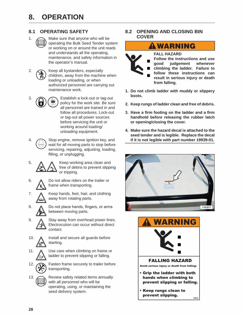
8.2 OPENING AND CLOSING BIN COVER
WARNING FALL HAZARD Follow the instructions and use good judgement whenever climbing the ladder. Failure to follow these instructions can result in serious injury or death from falling.
1. Do not climb ladder with muddy or slippery boots.
2. Keep rungs of ladder clean and free of debris.
3. Have a firm footing on the ladder and a firm handhold before releasing the rubber latch or opening/closing the cover.
4. Make sure the hazard decal is attached to the seed tender and is legible. Replace the decal if it is not legible with part number 19939-01.

29
1. Carefully climb the ladder.
2. Release the rubber latch on the cover.
3. Raise the cover and push it forward.
4. Continue to push the cover forward until it is fully opened.
5. When�the�bin�is�filled,�close�the�cover�and�lock�it in place with the rubber latch.
IMPORTANTMake sure the cover is closed and the rubber latch is locked in place before towing the seed tender. Failure to lock the rubber latch could allow the cover to blow open, resulting in damage to the
unit.
8.3 OPERATIONThis Operation section provides a step-by-step procedure�for�first�loading�seed�into�the�seed�tender at the farm and then unloading it in the field.
8.3.1 Loading (Filling Seed Tender)
1. Connect the seed tender to a suitable towing vehicle. Follow all related safety instructions in the Towing and the Safety sections of this manual.
IMPORTANTThe seed tender, when fully loaded, can weigh
7,500 lbs. (3,402 kg.). Ensure the tow vehicle has the capacity to safely tow a fully loaded seed tender.
2. Before loading, shut off the engine of the tow vehicle, set the parking brake, and remove the ignition key, and wait for all moving parts to stop before leaving cab.

30
3. Open�the�cover�of�the�seed�tender�and�fill�it�with seed from a storage box, storage bag, or other means. Follow the safety instructions in the Opening and Closing Bin Cover section of this manual.
4. When�the�bin�is�filled,�close�the�cover�and�lock�it in place with the rubber latch.
IMPORTANTMake sure the cover is closed and the rubber latch is locked in place before towing the seed tender. Failure to lock the rubber latch could allow the cover to blow open, resulting in damage to the
unit.
5. Move the unit to the location of the planting equipment following all safe towing practices.
8.3.2 Unloading Seed Tender
The seed tender will only unload from the left side.
1. Position the seed tender near the planter.
2. Before unloading, shut off the engine of the tow vehicle, set the parking brake, and remove the ignition key, and wait for all moving parts to stop before leaving the cab.
3. Check the surrounding area for overhead power lines that would contact the auger tube in its raised position. Contact with electricity can result in serious personal injury or death.
WARNINGELECTROCUTION HAZARD Avoid contact with overhead power lines or electrically powered objects.
1. Be aware of your surroundings when raising or lowering any part of the equipment.
2. Maintain at least 20 feet between the equipment and any electrical hazard.
3. Contact with electricity can result in serious personal injury or death.
4. Unlatch the rubber tie-down strap from the delivery spout.
5. Lower the delivery spout to the ground.
6. Make sure the auger cable is threaded into the hole in the end of the auger. Damage to the auger can occur if the cable is not properly inserted.
31
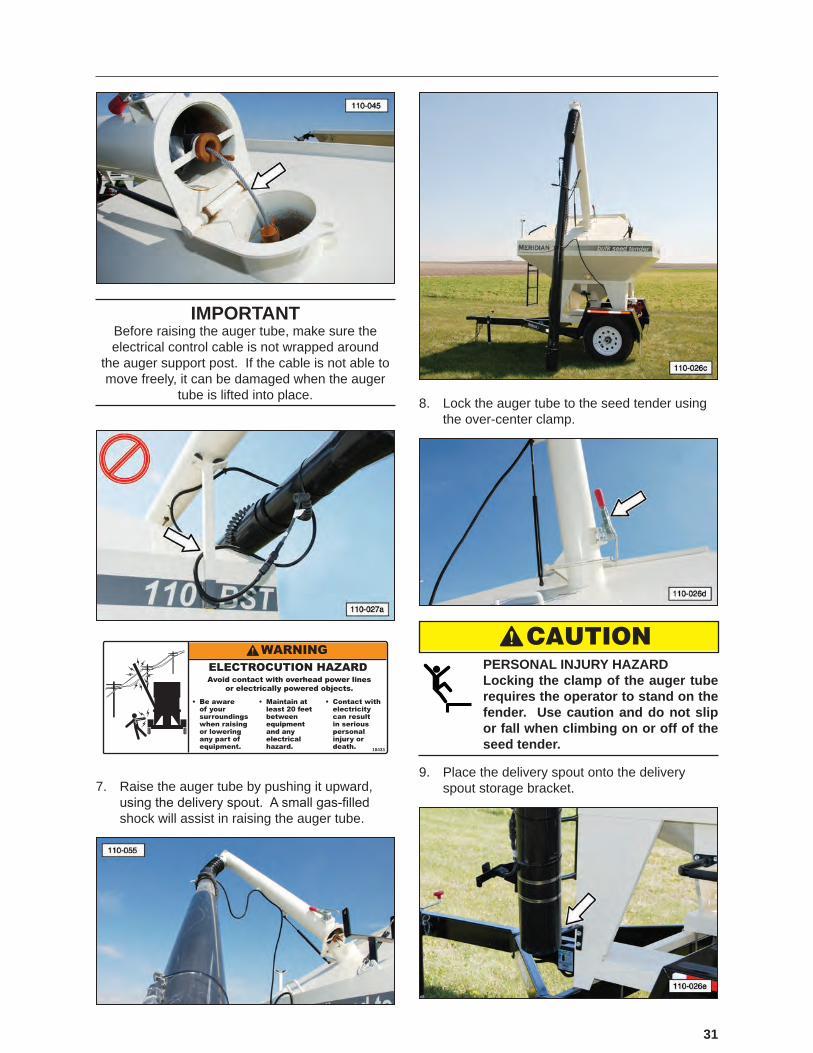
IMPORTANTBefore raising the auger tube, make sure the electrical control cable is not wrapped around
the auger support post. If the cable is not able to move freely, it can be damaged when the auger
tube is lifted into place.
18433
7. Raise the auger tube by pushing it upward, using�the�delivery�spout.��A�small�gas‑filled�shock will assist in raising the auger tube.
8. Lock the auger tube to the seed tender using the over-center clamp.
CAUTION PERSONAL INJURY HAZARD Locking the clamp of the auger tube requires the operator to stand on the fender. Use caution and do not slip or fall when climbing on or off of the seed tender.
9. Place the delivery spout onto the delivery spout storage bracket.
32
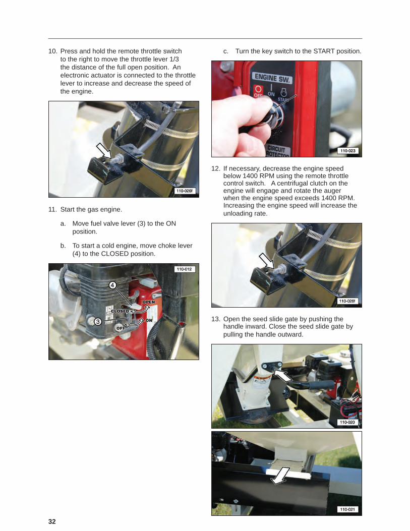
10. Press and hold the remote throttle switch to the right to move the throttle lever 1/3 the distance of the full open position. An electronic actuator is connected to the throttle lever to increase and decrease the speed of the engine.
11. Start the gas engine.
a. Move fuel valve lever (3) to the ON position.
b. To start a cold engine, move choke lever (4) to the CLOSED position.
c. Turn the key switch to the START position.
12. If necessary, decrease the engine speed below 1400 RPM using the remote throttle control switch. A centrifugal clutch on the engine will engage and rotate the auger when the engine speed exceeds 1400 RPM. Increasing the engine speed will increase the unloading rate.
13. Open the seed slide gate by pushing the handle inward. Close the seed slide gate by pulling the handle outward.

33
14. Fill the planting equipment.
a. Move the delivery spout to the seed box or bin and increase engine RPM to rotate the auger.
b. When the seed box or bin is full, reduce the engine RPM to low idle to stop the auger.
c. Move the delivery spout to the next box or�bin�and�increase�engine�RPM�to�fill�the�next one. Repeat this procedure until the remaining�boxes�or�bins�are�filled.
15. When the transfer of seed is complete, press the auger speed control switch to reduce the engine RPM and stop the auger.
16. Close the seed bin slide gate by pulling the handle outward.
IMPORTANTIf the unit will not be used again for an extended period of time, the auger tube should be cleared of all seed. This will help prevent the seed from
being clogged inside the tube.
17. Turn the gas engine off.
18. Place the engine’s fuel lever in the OFF position before towing the seed tender on the open road.
Shut off fuelwhen not in use.
19. Before towing the unit on the road, return the auger tube and delivery spout to its stored position. Latch the rubber tie-down strap over the delivery spout.
34
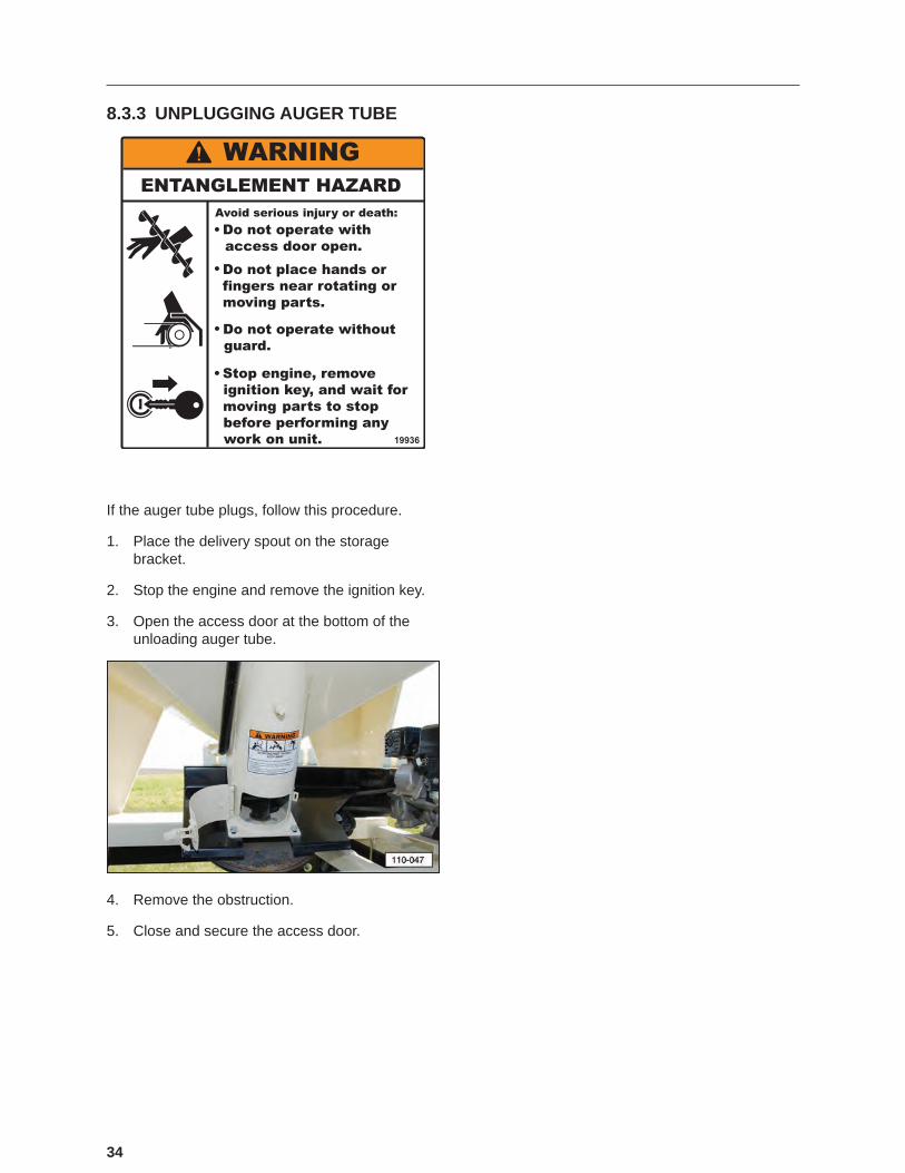
8.3.3 UNPLUGGING AUGER TUBE
If the auger tube plugs, follow this procedure.
1. Place the delivery spout on the storage bracket.
2. Stop the engine and remove the ignition key.
3. Open the access door at the bottom of the unloading auger tube.
4. Remove the obstruction.
5. Close and secure the access door.
35
9. STORAGE
9.1 STORAGE SAFETY1. Store the unit in an area away from human
activity.
2. Do not permit children to play on or around the stored machine.
3. Store the unit in a dry, level area. Support the frame with planks, if required.
9.2 GENERAL INFORMATIONAfter planting or when the machine will not be used for a period of time, completely inspect all major systems of the seed tender. Replace or repair any worn or damaged components to prevent unnecessary downtime at the beginning of the next season.
IMPORTANTTo prevent component damage, store the seed
tender in a dry, level area. If the seed tender is not attached to a trailer, support the frame with planks
to raise the unit off the ground.
9.3 PLACING IN STORAGE
CAUTION PERSONAL INJURY HAZARD Store the unit in an area away from human activity. To prevent the possibility of serious injury, do not permit children to play on or around the stored machine.
1. Remove all seed from the seed tender.
2. Place the gasoline engine fuel valve in the OFF position.
3. Thoroughly wash the machine with a pressure washer or water hose to remove all dirt, mud, or debris.
4. Inspect rotating parts for entangled material. Remove all entangled materials.
5. Check the condition of the auger and delivery spout. Replace or adjust, as required.
6. Check the condition of the centrifugal clutch reduction case, pulleys, idlers, and drive belt. Replace or adjust, as required.
7. Touch up paint nicks and scratches to prevent rusting.
8. Remove the ignition key and store in a secure place.
9. Remove the battery and store it in a cool, dry area on wooden blocks or a wooden pallet. Charge it monthly to maintain an adequate charge.
10. It is best to store the machine inside and if that is not possible, cover with a waterproof tarp and tie down securely.
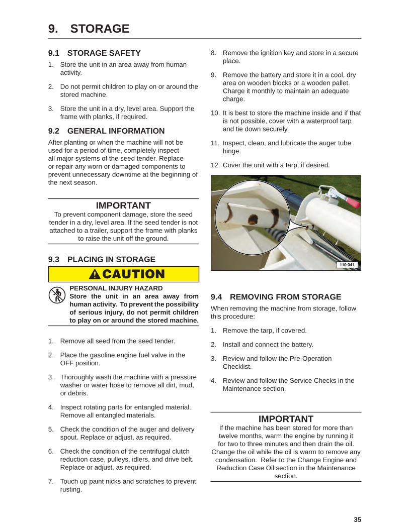
11. Inspect, clean, and lubricate the auger tube hinge.
12. Cover the unit with a tarp, if desired.
9.4 REMOVING FROM STORAGEWhen removing the machine from storage, follow this procedure:
1. Remove the tarp, if covered.
2. Install and connect the battery.
3. Review and follow the Pre-Operation Checklist.
4. Review and follow the Service Checks in the Maintenance section.
IMPORTANTIf the machine has been stored for more than twelve months, warm the engine by running it for two to three minutes and then drain the oil.
Change the oil while the oil is warm to remove any condensation. Refer to the Change Engine and Reduction Case Oil section in the Maintenance
section.
36
10. MAINTENANCE
10.1 SAFETY10.1.1 General Safety
1. Good maintenance is your responsibility. Poor maintenance is an invitation for trouble.
2. Follow good shop practices. Keep service area clean and dry. Be sure electrical outlets and tools are properly grounded. Use adequate light.
3. Ensure proper ventilation. Never operate the engine in a closed building. The exhaust fumes may cause asphyxiation.
4. STOP
Before working on this machine, shut off the engine and remove the ignition keys.
5. Never work under equipment unless it is securely blocked.
6.
Always use personal protection devices, such as eye, hand, and hearing protectors, when performing any service or maintenance.
7. OEM
Where replacement parts are necessary for periodic maintenance and servicing, genuine factory replacement parts must be used to restore your equipment to the original specifications.�The�manufacturer�will�not be responsible for injuries or damages caused by use of unapproved parts and/or accessories.
8. � �A�fire�extinguisher�and�first�aid�kit should be readily accessible while performing maintenance on this equipment.
9. Periodically tighten all bolts, nuts, and screws and ensure all cotter pins are properly installed to ensure the unit is in safe condition.
10. When completing a maintenance or service function, make sure all safety shields and devices are installed before placing the unit in service.
11. Turn OFF all electrical power and tag-out or lock-out the power source before performing any electrical test or before connecting or disconnecting valve coils or other electrical loads.
12. Never operate or test any function of the equipment when people are in an area of a potential crush hazard.
13. Disconnect all electronic device cables from the seed tender before performing any arc welding repair. Damage from high currents may cause internal electronic device damage.
10.1.2 Lock-Out or Tag-Out Safety
1. do not
operatesigned by
date
WARNING
Establish a formal Lock-Out or Tag-Out program for your operation.
2. Train all operators and service personnel before allowing them to work around the seed delivery system.
3. do not
operatesigned by
date
WARNING
Provide tags on the machine and a sign-up sheet to record tag-out details.
37
10.2 LUBRICATIONUse the Service Checks information in the Maintenance section to keep a record of all scheduled maintenance.
1. Use an SAE multi-purpose high temperature grease or a multi-purpose lithium base grease for the auger pivot hinge.
2. Use only a handheld grease gun for all greasing.
3. Wipe�grease�fitting�with�a�clean�cloth�before�greasing to avoid injecting dirt and grit.
4. Replace and repair broken zerks immediately.
5. If zerks will not take grease, remove and clean the�passageway.��Replace�fitting,�if�necessary.
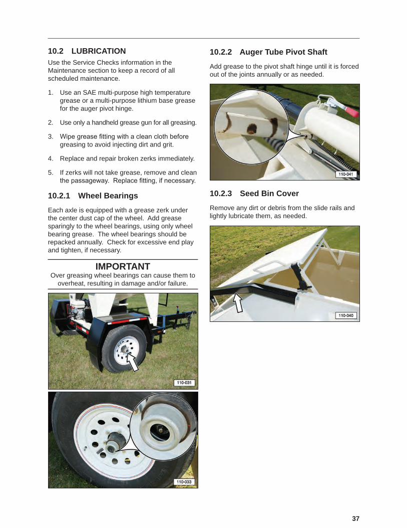
10.2.1 Wheel Bearings
Each axle is equipped with a grease zerk under the center dust cap of the wheel. Add grease sparingly to the wheel bearings, using only wheel bearing grease. The wheel bearings should be repacked annually. Check for excessive end play and tighten, if necessary.
IMPORTANTOver greasing wheel bearings can cause them to
overheat, resulting in damage and/or failure.
10.2.2 Auger Tube Pivot Shaft
Add grease to the pivot shaft hinge until it is forced out of the joints annually or as needed.
10.2.3 Seed Bin Cover
Remove any dirt or debris from the slide rails and lightly lubricate them, as needed.

38
10.3 BATTERYInspect the battery at least once every six months and before using the seed tender at the beginning of the season. Always follow the safety instructions when servicing a battery.
10.3.1 Battery Safety
1. � �Keep�all�sparks�and�flames�away�from�batteries, as gas given off by electrolyte is explosive.
2. Avoid contact with battery electrolyte: wash off any spilled electrolyte immediately because battery acid can cause severe chemical burns.
3. Wear safety glasses when working near batteries.
4. Do not tip batteries more than 45 degrees, to avoid electrolyte loss.
5. To avoid injury from spark or short circuit, disconnect the battery ground cable before servicing any part of the electrical system. Never short circuit the battery. It may explode.
6. Protect battery terminals, battery-charger terminals, and cables against accidental contact which can cause sparks, explosions, or component damage.
7. Never attempt to jump start a frozen battery.
10.3.2 Battery Replacement and Maintenance Tips
• Check the batteries at least every six months for low Voltage, leakage, etc.
• Always use the correct size and type of battery. Replace old batteries with a new SP-30 Lawn and Garden battery with 230 CCA and 290 CA ratings.
• Do not install the battery cable to the wrong terminal. Make sure the RED cable is connected to the + (plus) terminal and the BLACK cable is connected to the – (minus) terminal.
• Remove the batteries from the seed tender if not expected to be in use for several months.
• Use recommended practices when recharging a dead battery.
• Remove any corrosion from the battery post using a wire brush terminal cleaner. Corrosion can also be removed using a baking soda paste and water to neutralize and remove the acid from the battery terminals
• Dispose of old batteries properly.
10.3.3 Battery Maintenance
1. Make sure the tie-down strap is connected to the frame of the battery box and in good condition (not cracked, cut, or damaged).

39
2. The battery is not charged when the engine is operating. If the battery is not charging using an external charger, check the fuse. Replace the fuse if necessary.
10.4 ENGINEFor any questions concerning the Honda® engine not provided in this manual, refer to the OEM manual that was provided with the seed tender.
To contact Honda®, refer to the OEM Literature section in this manual.
10.4.1 Refuelling Safety
1. G
Handle fuel with care. It is highly flammable.
2. � �Allow�engine�to�cool�for�five�minutes�before refuelling. Clean up spilled fuel before restarting engine.
3. Do not refuel the machine while smoking�or�when�near�open�flame�or�sparks.
4. Fill fuel tank outdoors.
5. � �Prevent�fires�by�keeping�machine�clean�of accumulated trash, straw, grease, and debris.
10.4.2 Approved Fuel
Use unleaded automotive gasoline for all operating conditions. The fuel tank capacity is 3.6 liters (0.95 gals).
10.4.3 Engine Oil
Use a typical SAE 10W-30 or 10W-40 multi-viscosity motor oil for normal operating conditions. Consult your engine manual for the recommended oil in cold temperatures. The crankcase capacity is 0.60 liters (.63 US qts.).
10.4.4 Change Engine and Reduction Case Oil
1. Review the Operator’s Manual for the engine.
2. Allow the engine to cool before changing the oil. Draining works best when the oil is warm.
CAUTION BURN HAZARD Hot engine oil can burn skin.
3. Be sure the engine key switch is in the OFF position and the fuel valve is turned OFF.
4. Place a pan under drain plug (1) or (2). Remove the drain plug and allow the oil to drain for ten minutes.
5. Reinstall the drain plug and tighten.
6. Dispose of the oil in an approved container. Follow industrial disposal regulations.
7. Fill the engine or reduction case with SAE 10W-30 oil for general usage. If the engine is operated in more extreme conditions, refer to the OEM manual for oil recommendations.
8. Run the engine for one minute and recheck both oil levels. Add oil, as needed.
40
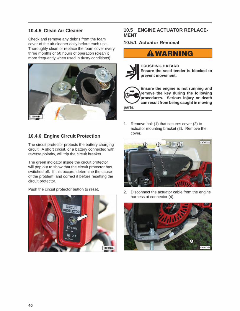
10.4.5 Clean Air Cleaner
Check and remove any debris from the foam cover of the air cleaner daily before each use. Thoroughly clean or replace the foam cover every three months or 50 hours of operation (clean it more frequently when used in dusty conditions).
10.4.6 Engine Circuit Protection
The circuit protector protects the battery charging circuit. A short circuit, or a battery connected with reverse polarity, will trip the circuit breaker.
The green indicator inside the circuit protector will pop out to show that the circuit protector has switched off. If this occurs, determine the cause of the problem, and correct it before resetting the circuit protector.
Push the circuit protector button to reset.
10.5 ENGINE ACTUATOR REPLACE-MENT10.5.1 Actuator Removal
WARNING
CRUSHING HAZARD Ensure the seed tender is blocked to prevent movement.
Ensure the engine is not running and remove the key during the following procedures. Serious injury or death can result from being caught in moving
parts.
1. Remove bolt (1) that secures cover (2) to actuator mounting bracket (3). Remove the cover.
2. Disconnect the actuator cable from the engine harness at connector (4).
41
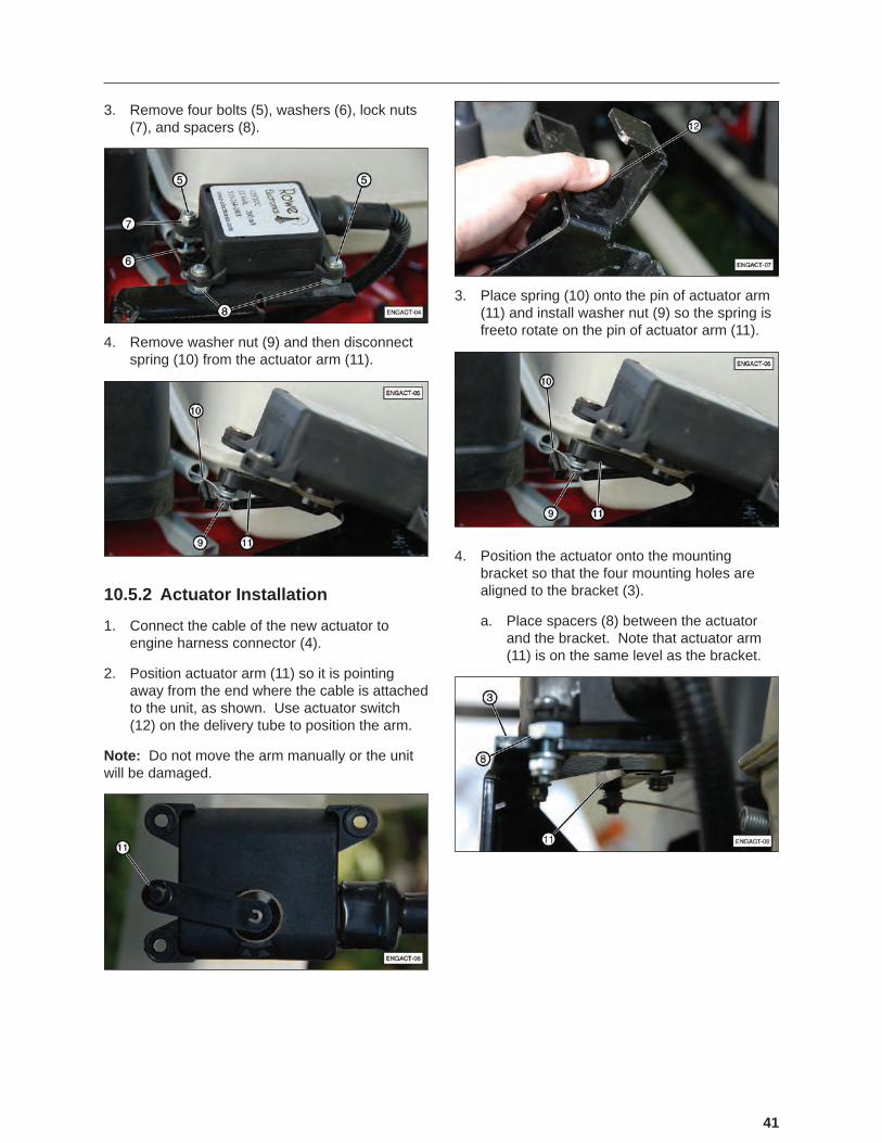
3. Remove four bolts (5), washers (6), lock nuts (7), and spacers (8).
4. Remove washer nut (9) and then disconnect spring (10) from the actuator arm (11).
10.5.2 Actuator Installation
1. Connect the cable of the new actuator to engine harness connector (4).
2. Position actuator arm (11) so it is pointing away from the end where the cable is attached to the unit, as shown. Use actuator switch (12) on the delivery tube to position the arm.
Note: Do not move the arm manually or the unit will be damaged.
3. Place spring (10) onto the pin of actuator arm (11) and install washer nut (9) so the spring is freeto rotate on the pin of actuator arm (11).
4. Position the actuator onto the mounting bracket so that the four mounting holes are aligned to the bracket (3).
a. Place spacers (8) between the actuator and the bracket. Note that actuator arm (11) is on the same level as the bracket.

42
b. If actuator arm (11) is below the bracket (as shown), the arm will continue to rotate and not function properly. The bracket serves as a stop for the arm.
c. Install four bolts (5), washers (6), and lock nuts (7), as shown. Note that the bolt nearest the engine is reversed for clearance with the lock nut on top.
Note: The four spacers are all positioned under the mounting plate no matter which direction the bolt is installed.
5. Reinstall the cover.
6. Ensure all personnel are clear of unit. Start the engine and test the actuator by pressing actuator switch (12) to ensure the engine speed increases and decreases as designed.
10.6 UNPLUGGING AUGER DELIV-ERY TUBE
IMPORTANTDo not operate the auger when it is plugged with
excess seed or is hindered from moving by a foreign object. Continued operation can cause damage.
If the auger becomes plugged, follow this procedure:
1. Stop the engine and remove the ignition key. Place a lock-out tag on the control box to prevent accidental starting of the conveyor.
2. Open the lower access door at the bottom of the auger and remove any excess seed or obstruction.
3. Close and secure the lower access door.
43
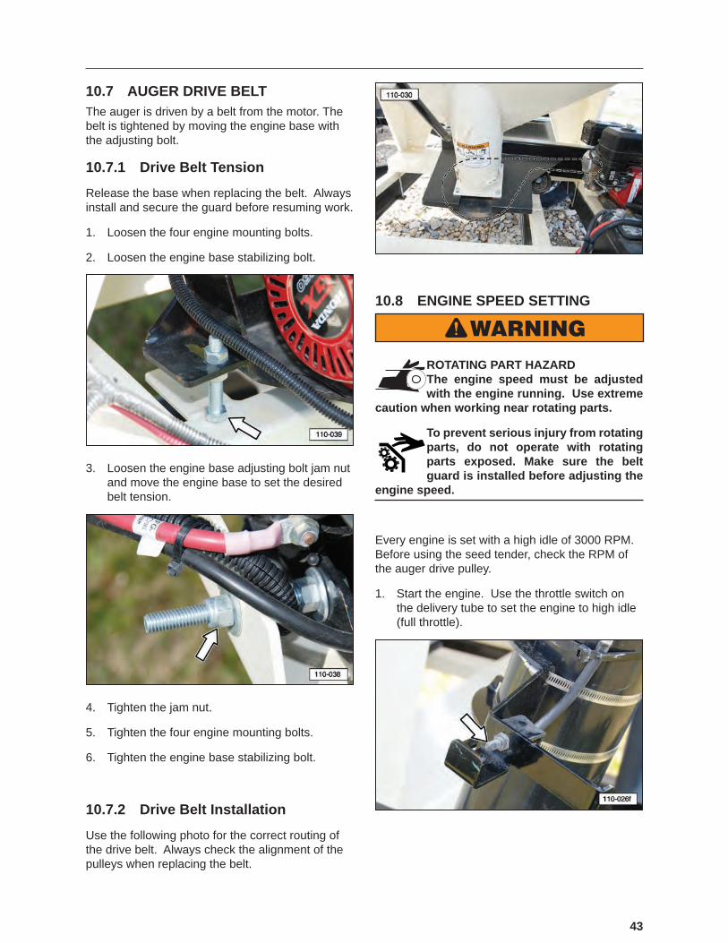
10.7 AUGER DRIVE BELTThe auger is driven by a belt from the motor. The belt is tightened by moving the engine base with the adjusting bolt.
10.7.1 Drive Belt Tension
Release the base when replacing the belt. Always install and secure the guard before resuming work.
1. Loosen the four engine mounting bolts.
2. Loosen the engine base stabilizing bolt.
3. Loosen the engine base adjusting bolt jam nut and move the engine base to set the desired belt tension.
4. Tighten the jam nut.
5. Tighten the four engine mounting bolts.
6. Tighten the engine base stabilizing bolt.
10.7.2 Drive Belt Installation
Use the following photo for the correct routing of the drive belt. Always check the alignment of the pulleys when replacing the belt.
10.8 ENGINE SPEED SETTING
WARNINGROTATING PART HAZARD The engine speed must be adjusted with the engine running. Use extreme
caution when working near rotating parts.
To prevent serious injury from rotating parts, do not operate with rotating parts exposed. Make sure the belt guard is installed before adjusting the
engine speed.
Every engine is set with a high idle of 3000 RPM. Before using the seed tender, check the RPM of the auger drive pulley.
1. Start the engine. Use the throttle switch on the delivery tube to set the engine to high idle (full throttle).
44
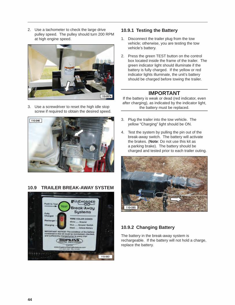
2. Use a tachometer to check the large drive pulley speed. The pulley should turn 200 RPM at high engine speed.
3. Use a screwdriver to reset the high idle stop screw if required to obtain the desired speed.
10.9 TRAILER BREAK-AWAY SYSTEM
10.9.1 Testing the Battery
1. Disconnect the trailer plug from the tow vehicle; otherwise, you are testing the tow vehicle’s battery.
2. Press the green TEST button on the control box located inside the frame of the trailer. The green indicator light should illuminate if the battery is fully charged. If the yellow or red indicator lights illuminate, the unit’s battery should be charged before towing the trailer.
IMPORTANTIf the battery is weak or dead (red indicator, even after charging), as indicated by the indicator light,
the battery must be replaced.
3. Plug the trailer into the tow vehicle. The yellow “Charging” light should be ON.
4. Test the system by pulling the pin out of the break-away switch. The battery will activate the brakes. (Note: Do not use this kit as a parking brake). The battery should be charged and tested prior to each trailer outing.
10.9.2 Changing Battery
The battery in the break-away system is rechargeable. If the battery will not hold a charge, replace the battery.
45
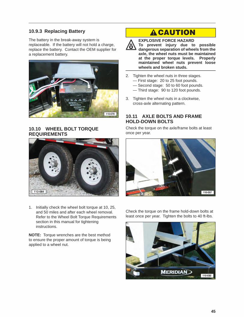
10.9.3 Replacing Battery
The battery in the break-away system is replaceable. If the battery will not hold a charge, replace the battery. Contact the OEM supplier for a replacement battery.
10.10 WHEEL BOLT TORQUE REQUIREMENTS
1. Initially check the wheel bolt torque at 10, 25, and 50 miles and after each wheel removal. Refer to the Wheel Bolt Torque Requirements section in this manual for tightening instructions.
NOTE: Torque wrenches are the best method to ensure the proper amount of torque is being applied to a wheel nut.
CAUTION EXPLOSIVE FORCE HAZARD To prevent injury due to possible dangerous separation of wheels from the axle, the wheel nuts must be maintained at the proper torque levels. Properly maintained wheel nuts prevent loose wheels and broken studs.
2. Tighten the wheel nuts in three stages. — First stage: 20 to 25 foot pounds. — Second stage: 50 to 60 foot pounds. — Third stage: 90 to 120 foot pounds.
3. Tighten the wheel nuts in a clockwise, cross-axle alternating pattern.
10.11 AXLE BOLTS AND FRAME HOLD-DOWN BOLTSCheck the torque on the axle/frame bolts at least once per year.
Check the torque on the frame hold-down bolts at least once per year. Tighten the bolts to 40 ft-lbs.

46
10.12 SERVICE RECORD CHARTThe chart on the following page should be copied and�filled�out�as�maintenance�is�performed�on�the�machine. Refer to the Lubrication, Maintenance, and Service sections for additional instructions.
Date
Serviced by8 hours or daily
Check Engine Fluid LevelsCheck Reduction Case Oil LevelTest Break-Away Brake SystemInspect TiresCheck Drive Belt Tension and Alignment
50 Hours or Weekly
Clean Engine Air Intake FilterCheck Tire PressureCheck Drive Belt Tension and Alignment
200 Hours or Semi/Annual
Adjust Brakes
Inspect Brake Magnets
Battery - Make sure strap is securely holding battery onto frame, check electrolyte levels in the cells, and clean terminals to remove any dirt or corrosion.
400 hours or annually
Change Engine OilChange Reduction Case OilCheck Wheel Bolt TorqueCheck Frame Hold-DownsInspect Brake Lining Wear, Brake Cylinder, and Brake WiringRepack Wheel Bearings and Check Hub for WearInspect Axle Grease SealInspect Springs for WearInspect all electrical wiring connections for looseness or corrosion. Tighten and/or seal, as necessary.Thoroughly Clean Machine
47
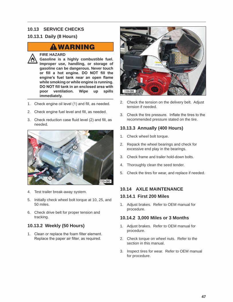
10.13 SERVICE CHECKS10.13.1 Daily (8 Hours)
WARNING FIRE HAZARD Gasoline is a highly combustible fuel. Improper use, handling, or storage of gasoline can be dangerous. Never touch or fill a hot engine. DO NOT fill the engine’s fuel tank near an open flame while smoking or while engine is running. DO NOT fill tank in an enclosed area with poor ventilation. Wipe up spills immediately.
1. Check�engine�oil�level�(1)�and�fill,�as�needed.
2. Check�engine�fuel�level�and�fill,�as�needed.
3. Check�reduction�case�fluid�level�(2)�and�fill,�as�needed.
4. Test trailer break-away system.
5. Initially check wheel bolt torque at 10, 25, and 50 miles.
6. Check drive belt for proper tension and tracking.
10.13.2 Weekly (50 Hours)
1. Clean�or�replace�the�foam�filter�element.��Replace�the�paper�air�filter,�as�required.
2. Check the tension on the delivery belt. Adjust tension if needed.
3. Check�the�tire�pressure.��Inflate�the�tires�to�the�recommended pressure stated on the tire.
10.13.3 Annually (400 Hours)
1. Check wheel bolt torque.
2. Repack the wheel bearings and check for excessive end play in the bearings.
3. Check frame and trailer hold-down bolts.
4. Thoroughly clean the seed tender.
5. Check the tires for wear, and replace if needed.
10.14 AXLE MAINTENANCE10.14.1 First 200 Miles
1. Adjust brakes. Refer to OEM manual for procedure.
10.14.2 3,000 Miles or 3 Months
1. Adjust brakes. Refer to OEM manual for procedure.
2. Check torque on wheel nuts. Refer to the section in this manual.
3. Inspect tires for wear. Refer to OEM manual for procedure.

48
10.14.3 6,000 Miles or 6 Months
1. Inspect brake magnets for wear. Refer to OEM manual for procedure.
2. Inspect suspension parts for wear. Refer to OEM manual for procedure.
10.14.4 12,000 Miles or 12 Months
1. Inspect brake lining wear, check brake cylinder for leaks, and inspect brake wiring for damage. Refer to OEM manual for procedure.
2. Grease the wheel bearings and check the hub for wear. Refer to OEM manual for procedure.
3. Inspect grease seal for leakage. Refer to OEM manual for procedure.
4. Inspect springs for any wear or loss of arch. Refer to OEM manual for procedure.
10.15 TIRESCheck the tires for normal and/or abnormal tire wear. Replace tires that are damaged or worn beyond normal tread life. Refer to the axle OEM manual for a Tire Wear Diagnostic Chart.
Replace the tires with Meridian part number 18131 or an equivalent tire:
3T235/80R16 TR643
Load Range E For Trailer Service Only
10.16 WELDING REPAIRS Repair welding must be done with care and with procedures that may be beyond the capabilities of the ordinary welder.
Before performing any type of welding repair to the seed tender, contact Meridian for approval.
WARNING PERSONAL INJURY HAZARD Repairs or modifications to the trailer, trailer tongue, or trailer hitch can result in serious injury or death should these repairs fail.
IMPORTANT NOTICEAnyone performing a welding repair should be certified�in�accordance�to�the�American�Welding�
Society (AWS) standards.
49
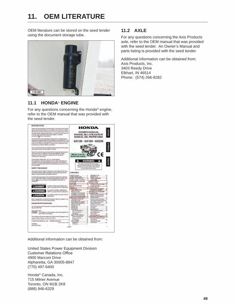
11. OEM LITERATURE
OEM literature can be stored on the seed tender using the document storage tube.
11.1 HONDA® ENGINEFor any questions concerning the Honda® engine, refer to the OEM manual that was provided with the seed tender.
Additional information can be obtained from: United States Power Equipment Division Customer�Relations�Office 4900 Marconi Drive Alpharetta, GA 30005-8847 (770) 497-6400
Honda® Canada, Inc. 715 Milner Avenue Toronto, ON M1B 2K8 (888) 946-6329
11.2 AXLEFor any questions concerning the Axis Products axle, refer to the OEM manual that was provided with the seed tender. An Owner’s Manual and parts listing is provided with the seed tender.
Additional information can be obtained from: Axis Products, Inc. 3403 Reedy Drive Elkhart, IN 46514 Phone: (574) 266-8282

50
12. TROUBLESHOOTING
12.1 TROUBLESHOOTING CHART
PROBLEM CAUSE SOLUTIONEngine will not start. No fuel. Fill the fuel tank.
Low engine oil. Fill the crankcase with oil.Cold engine. Open choke.Ignition key switch off. Turn ignition key switch on.Battery dead. Recharge or replace battery.Engine problem. Refer to engine manual.
Auger will not start. Not rotating. Start engine and increase speed above 1400 RPM.
Drive pulley connection or auger coupling.
Repair or replace.
Drive belt slipping. Increase belt tension.No hydraulic oil in reduction case. Check oil level.Failed centrifugal clutch. Replace clutch.
Electrical functions are not work-ing properly.
Battery cable or battery. Check battery cable and make sure battery is fully charged.
Improper ground. Check for proper grounding of electrical circuit.
Remote throttle doesn’t work. No input power. Check charge of battery. Recharge or replace, as required.Check connections in the remote throttle harness. Be sure connectors are clean and terminals�are�firmly�pushed�together.

51
13. WARRANTY
13.1 WARRANTY STATEMENT
Limited Materials and Workmanship Warranty
For Bulk Seed Tenders
Meridian Manufacturing Group (hereinafter referred to as the Manufacturer) hereby warrants the Bulk Seed Tender(s) sold by it to be free from any defect in material or workmanship under normal use and service for a period of one (1) year from the date of shipment. The Manufacturer’s obligation under this warranty shall be limited to the repair or replacement only, FOB the original point of shipment, of any defective parts or portions of the seed tender or accessories manufactured by Meridian. Any warranty claim must be reported to the Manufacturer within one (1) year from the date of shipment.
THIS WARRANTY IS SUBJECT TO THE FOLLOWING LIMITATIONS, PROVISIONS AND CONDITIONS:
1. This warranty does not apply:
a) To any product sold by the Manufacturer where it is used in areas exposed to corrosive or aggressive conditions including salt water, acids, alkaloid, ash, cement dust, animal waste or other corrosive chemicals from either inside or outside the bin.
b) For failures or defects arising out of damage during shipment or during storage on site.c) To materials replaced or repaired under this warranty except to the extent of the remainder of the applicable warranty.d) To damage resulting from misuse, negligence, accident or improper site preparation by others.e) Iftheproducthasbeenalteredormodifiedbyothers.f) If in the case of coating failures the failure is the result of damage, lack of proper maintenance or failure to remove road salt or other contaminants
that may have come in contact with the bin surface.g) To loss of time, inconvenience, loss of material, down time or any other consequential damage.h) For a function that is different than original designed intent.
2. TheobligationoftheManufacturerunderthiswarrantyshallnotariseunlesstheManufacturerisnotifiedandthiswarrantyispresentedtogetherwithawrittenstatementspecifyingtheclaimordefectwithinthirty(30)daysafterthefailureisfirstdetectedormadeknowntotheownerandwithinone(1)year from the shipment date. The Manufacturer in its sole discretion shall determine if the claim is valid and whether correction of the defect or failure shall be made by repair or replacement of the materials.
3. Thecoatingwarrantyisbasedonthemanufacturer’sperformancespecificationforPolyesterPowderfinishesanddoesnotincluderepairofminorblemishes or rusting that is normally part of the general maintenance of the seed tender. This warranty does not cover excessive wear on interior coatings. SeeattachmentforfullPerformanceSpecificationdetailsonPolyesterPowderFinishes.
4. The obligation of the Manufacturer hereunder extends only to the original owner and to the Meridian dealer to whom the materials may have been initially sold. This warranty shall not be subject to any assignment or transfer without the written consent of the Manufacturer.
5. Thecustomershallacknowledgethatithasmadeitsownindependentdecisiontoapprovetheuseofthesuppliedmaterialsandalsothespecificfabricationandconstructionproceduresutilizedtocompletetheseedtender,andhassatisfieditselfastothesuitabilityoftheseproductsforthisparticularapplication.
6. The foregoing sets forth the only warranties applicable to said materials and said warranties are given expressly and in lieu of all other warranties, expressedorimplied,statutoryorotherwise,ofmerchantabilityorfitnessforaparticularpurposeandallwarrantieswhichexceedordifferfromsaidwarranties herein are disclaimed by the Manufacturer.
7. The owners sole and exclusive remedy against the Manufacturer shall be limited to the applicable warranty set forth herein and the endorsements, if any, issued together with this document and no other remedy (including but not limited to the recovery of assembly or disassembly costs, shipping costs, direct,incidental,special,indirectorconsequentialdamagesforlostprofits,lostsales,injurytopersonorpropertyoranyotherloss,whetherarisingfrombreach of contract, breach of warranty, tort, including negligence, strict liability or otherwise) shall be available to the owner or Meridian Dealer or any other person or entitles whether by direct action or for contribution or indemnity or otherwise.
8. ThefinancialobligationoftheManufacturerunderthiswarrantyshallbelimitedtotherepairorreplacementoftheproductasoriginallysuppliedandinno event shall exceed the original cost of the product supplied.
9. The Manufacturer shall not have any obligation under any warranty herein until all accounts for materials, installation and erection of the said product thereof and for labor and other work performed by the Manufacturer or its dealers have been paid in full by the owner.
Warranty Claim Procedure
1. Registering product with Meridian Manufacturing.
2. Contact the dealer unit was purchased from upon discovery of any defects.
3. A completed warranty claim form submitted by dealer to Meridian warranty representative for review and course of action.
4. Warranty repair work will only be performed by Meridian, the dealer or an approved representative. No warranty work completed prior to approval. Failure to follow procedure may affect any or all reimbursement.
5. Claims will be adjudicated at the sole discretion of the manufacturer and in accordance with the terms and conditions of the applicable limited warranty.
6. A complete list of warranty procedures can be procured from the Warranty Department or found in your owner’s manual.
Effective July 1, 2009

52
14. PARTS
The following pages contain a list of serviceable parts for the 110BST Seed Tender unit.
Parts are available from your authorized Dealer Parts Department.
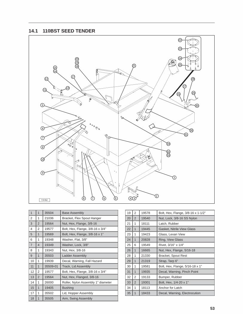
53
14.1 110BST SEED TENDER
110-062
21 25
28
27
26 29
30
31
35
34
3233
1
2345678
9
10
8
7
6
5
11
12
13
17
1415 18
1920 24
23
22
1 1 35504 Base Assembly
2 1 21036 Bracket, Flex Spout Hanger
3 2 19564 Nut, Hex, Flange, 3/8-16
4 2 19577 Bolt, Hex, Flange, 3/8-16 x 3/4”
5 1 19569 Bolt, Hex, Flange, 3/8-16 x 1”
6 1 19348 Washer, Flat, 3/8”
7 4 19349 Washer, Lock, 3/8”
8 1 19343 Nut, Hex, 3/8-16
9 1 35503 Ladder Assembly
10 1 19939 Decal, Warning, Fall Hazard
11 1 35509-01 Track, Lid Assembly
12 2 19577 Bolt, Hex, Flange, 3/8-16 x 3/4”
13 2 19564 Nut, Hex, Flanged, 3/8-16
14 1 26000 Roller, Nylon Assembly 1” diameter
15 1 19405 Bushing
17 1 35502 Lid, Hopper Assembly
18 1 35505 Arm, Swing Assembly
19 2 19578 Bolt, Hex, Flange, 3/8-16 x 1-1/2”
20 2 19540 Nut, Lock, 3/8-16 SS Nylon
21 1 18111 Latch, Rubber
22 1 19445 Gasket, Nitrile View Glass
23 1 19423 Glass, Lexan View
24 1 20828 Ring, View Glass
25 6 19549 Rivet, 3/16" x 1/4"
26 1 16665 Nut, Hex, Flange, 5/16-18
28 1 21330 Bracket, Spout Rest
29 1 21319 Strap, Tarp 6”
30 1 19581 Bolt, Hex, Flange, 5/16-18 x 1”
31 1 19935 Decal, Warning, Pinch Point
32 2 19133 Bumper, Rubber
33 2 19301 Bolt, Hex, 1/4-20 x 1”
34 1 18113 Anchor for Latch
35 1 18433 Decal, Warning, Electrocution
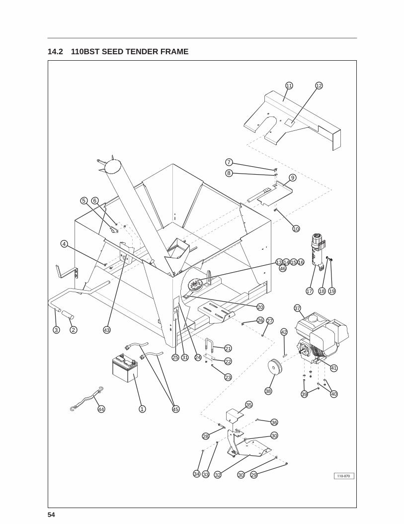
54
14.2 110BST SEED TENDER FRAME
11 12
7
89
10
13 14 15 1646
17 18 19
20
26
21
22
23
2425 31
1 4544
2 43
4
5 6
3
27
42
37
41
39 4038
35
36
30
2930323334
28
110-070

55
1 1 21286 Battery, SP30
2 1 19447 Handle Grip
3 1 21065 Slide Gate Handle
4 2 19568 Bolt, 5/16-18 X 3/4” Flanged
5 1 19404 Bushing, Nylon 1”
6 2 19318 Nut, Hex, 5/16-18 Flanged
7 2 19560 Bolt, Hex, 1/4-20 X 3/4”
8 2 19307 Washer, 1/4”
9 1 21063 Gate, Slide
10 2 19128 Nut, Hex, 1/4-20 Nylon
11 1 21307 Guard, Belt
12 1 19937 Decal, Warning, Rotating Part Hazard
13 1 21253 Pulley, Idler, 5”
14 3 19372 Washer, 1/2”
15 1 19127 Nut, Lock, 1/2-13 Nylon
16 1 19356 Bolt, Hex, 1/2-13 x 2
17 1 18128 Holder, Manual
18 3 19560 Bolt, Hex, 1/4-20 UNC x 3/4” HHCS
19 3 19128 Nut, Hex, 1/4-20 UNC, Nylon
20 1 18435 Decal, Danger, Entanglement Hazard
21 4 19120 U-Bolt, 1/2-13 x 3-1/8 x 9”
22 4 21278-03 Strap, Tie Down
23 8 19127 Nut, Lock, 1/2-13
24 1 19944 Decal, Notice, Product Warranty
25 1 19934 Decal, Caution, Read The Manual
26 1 19348 Washer, Flat, 3/8”
27 1 19347 Nut, Lock, 3/8-16 Nylon
28 1 19330 Bolt, Hex, 3/8-16 x 3” Full Thread
29 1 19343 Nut, Hex, 3/8-16
30 2 19348 Washer, Flat, 3/8”
31 1 — Decal, Serial Number
32 1 21424 Bracket, Actuator Assembly
33 1 19307 Washer, 1/4”
34 1 19128 Nut, Hex, 1/4-20 Nylon
35 1 21425 Guard, Actuator
36 1 19560 Bolt, Hex, 1/4-20 x 3/4”
37 1 21255 Motor, Honda 5.5 Hp Electric Start
38 1 21251 Pulley, 3” Honda Drive
39 4 19347 Nut, Lock, 3/8-16 Nylon
40 4 19348 Washer, Flat, 3/8”
41 4 19626 Bolt, Hex, Flanged, 3/8-16 x 1-3/4”
42 1 21261 Key, Square
43 1 19931 Decal, Push to Open
44 1 21319 Strap, Rubber, Battery Hold Down
45 1 18657 Cable, Battery
46 1 21247 Bracket, Idler Pulley

56
14.3 110BST ENGINE AND ACTUATOR
110-061
1 23
4
5
6
8
9
10
13
14
15
16
14
19
18
17
24
23
22
12
21
11
20
1 1 19560 Bolt, Hex, 1/4-20 x 3/4”2 1 21425 Plate, Actuator Cover3 1 19307 Washer, 1/4”4 1 19128 Nut, Hex, 1/4-20 Nylon5 1 21438 Actuator6 4 19628 Screw, Round Head, #8-36 x 1”7 — — —
8 5 19629 Washer, Flat, 5/32”9 3 19630 Nut, Hex Lock, #8-3610 1 21270-01 Nut, Push, 7/32”11 1 21437 Spring, Actuator12 1 21270 Holder, Throttle Cable Wire
13 1 21255 Motor, Honda 5.5 Hp Electric Start14 2 19343 Nut, Hex, 3/8-1615 1 21424 Bracket, Actuator Assembly16 1 19330 Bolt, Hex, 3/8-16 x 3”17 4 19347 Nut, Lock, 3/8-16 Nylon18 4 19348 Washer, Flat, 3/8”19 4 19626 Bolt, Hex, Flanged, 3/8-16 x 1-3/4”20 1 19991 Decal, Recharge Battery21 1 36106 Harness, Lower Actuator22 1 21251 Pulley23 1 21261 Key, Square24 1 21114 Belt, Drive BB68

57
14.4 110BST UPPER AUGER TUBE
B
DETAIL B
12
11
13
14
15
10
16
21
17
18
19
20
5
6
34
2
7
22
8
9
1
110-057
1 1 36003 Tube, Fold Over Auger Assembly
2 1 19123 Latch, Fold Over Auger
3 4 19309 Bolt, Hex, 5/16-18 x 3/4”
4 4 19318 Nut, Hex, Flanged, 5/6-18
5 1 19284 Pin, Spring, 3/16” x 1-1/8”
6 1 21223 Pin, Hinge
7 1 19283 Zerk, Grease
8 1 21445 Cable, Auger Alignment
9 1 21333-02 Shaft, Top Auger Bottom Drive
10 1 19405 Bushing
11 1 18714 Auger, Top Assembly
12 1 21453 Shaft, Auger Tail
13 1 19315 Bolt, Carriage, 5/16-18 x 3/4”
14 2 21259 Flange, Bearing 52 mm Zinc
15 1 21258 Bearing
16 2 19308 Washer, Lock, 1/4”
17 2 19307 Washer, Flat, 1/4”
18 1 21222-03 Cap, 6” Top Bearing
19 2 19582 J-Bolt, 1/4-20 x 1-1/2”
20 3 19586 Nut, Lock, 5/16-18 Nylon
21 2 19305 Nut, Hex, 1/4-20
22 1 18433 Decal, Danger, Electrocution
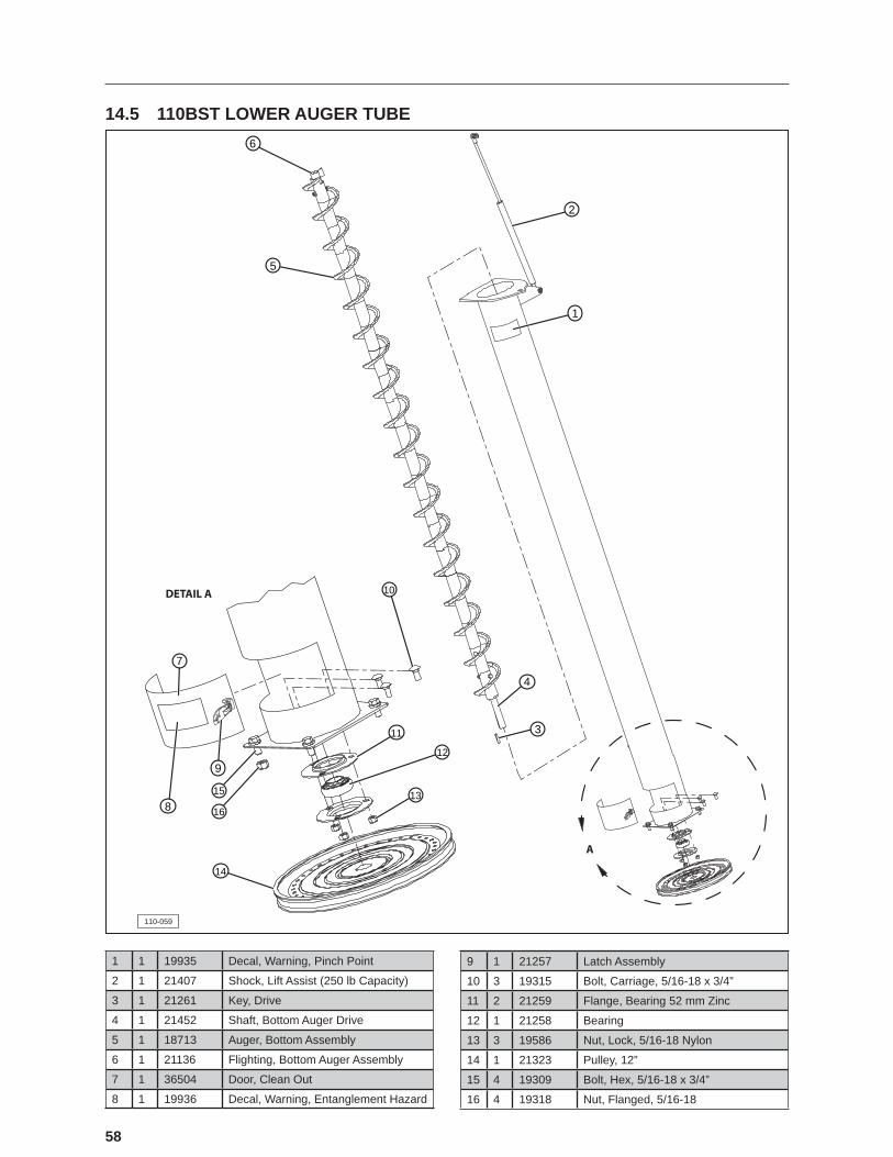
58
14.5 110BST LOWER AUGER TUBE
A
110-059
DETAIL A
7
9
8
14
15
16
10
1
5
6
2
11
12
13
3
4
1 1 19935 Decal, Warning, Pinch Point
2 1 21407 Shock, Lift Assist (250 lb Capacity)
3 1 21261 Key, Drive
4 1 21452 Shaft, Bottom Auger Drive
5 1 18713 Auger, Bottom Assembly
6 1 21136 Flighting, Bottom Auger Assembly
7 1 36504 Door, Clean Out
8 1 19936 Decal, Warning, Entanglement Hazard
9 1 21257 Latch Assembly
10 3 19315 Bolt, Carriage, 5/16-18 x 3/4”
11 2 21259 Flange, Bearing 52 mm Zinc
12 1 21258 Bearing
13 3 19586 Nut, Lock, 5/16-18 Nylon
14 1 21323 Pulley, 12”
15 4 19309 Bolt, Hex, 5/16-18 x 3/4”
16 4 19318 Nut, Flanged, 5/16-18
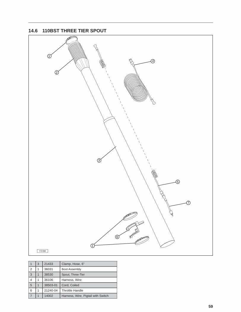
59
14.6 110BST THREE TIER SPOUT
110-060
1
2
3
4
5
7
6
1
1 3 21433 Clamp, Hose, 6”
2 1 36031 Boot Assembly
3 1 38530 Spout, Three-Tier
4 1 36106 Harness, Wire
5 1 38503-01 Cord, Coiled
6 1 21240-04 Throttle Handle
7 1 14002 Harness, Wire, Pigtail with Switch

60
14.7 110BST TRAILER
110-088
5
21
3 84
10 11
9
213
14
12
7
6
1 1 — Trailer
2 1 19275 Battery Breakaway BA10-1503 2 19225 Safety Chain with Hook4 1 18164 Jack Stand A-Frame Mount
5 4 18118 Fender Slip Tape
6 2 18153 Reflective�Tape,�Fender
7 2 19274 Mud Flap
8 2 18151 Clearance Light
9 2 19438 Plug
10 2 18117 Tail Light
11 1 18119 Reflective�Tape,�Rear
12 1 18193 Axle, 7,000 lbs
13 2 18131 Tire, ST235/80R16
14 16 18991 Nut, Lug, 9/16-18

61
NOTES

62
NOTES


64
Winkler OfficeBox 760, 275 Hespler Ave.Winkler, MB R6W 4A8PH: 204.325.7883TF: 800.665.7259FX: 204.325.5556
Storm Lake Office2902 Expansion Blvd.Storm Lake, IA 50588PH: 712.732.1780TF: 800.437.2334FX: 712.732.1028
Lethbridge Office3125 - 24 Ave. N.Lethbridge, AB T1H 5G2PH: 403.320.7070TF: 800.661.1436FX: 403.320.7579
Camrose Office4232 - 38 St.Camrose, AB T4V 4B2PH: 780.672.4516TF: 800.830.2467FX: 780.672.4759
© 2012 Meridian Manufacturing Group. Registered Trademarks Used Under License. Printed in US (09/2012) Form No. 19786