Embed Size (px)
Citation preview
Annex to ED Decision 2013/011/R
European Aviation Safety Agency
Certification Specifications and
Acceptable Means of Compliance
for
Tethered Gas Balloons
CS-31TGB
Initial Issue
1 July 20131
1 For the date of entry into force of this Amendment, kindly refer to Decision 2013/011/R in the Official Publication of the Agency
Annex to ED Decision 2013/011/R
C-1
CONTENTS
CS–31TGB — Tethered Gas Balloons
BOOK 1 – CERTIFICATION SPECIFICATIONS
SUBPART A — GENERAL
CS 31TGB.1 APPLICABILITY
CS 31TGB.2 DEFINITIONS (SEE AMC1 31TGB.2)
SUBPART B — FLIGHT
CS 31TGB.12 PROOF OF COMPLIANCE
CS 31TGB.14 MASS LIMITS (SEE AMC1 31TGB.14)
CS 31TGB.20 CONTROLLABILITY
SUBPART C — STRUCTURE
CS 31TGB.21 LOADS
CS 31TGB.22 IN-SERVICE LOAD CASES (SEE AMC1 31TGB.22)
CS 31TGB.23 LOAD FACTORS
CS 31TGB.25 FACTORS OF SAFETY
CS 31TGB.27 STRENGTH AND PROOF OF STRENGTH
SUBPART D — DESIGN AND CONSTRUCTION
CS 31TGB.31 GENERAL
CS 31TGB.33 MATERIALS
CS 31TGB.35 FABRICATION METHODS
CS 31TGB.36 STRESS CONCENTRATIONS
CS 31TGB.37 FASTENERS
CS 31TGB.39 PROTECTION OF PARTS (SEE AMC1 31TGB.39)
CS 31TGB.41 INSPECTION PROVISIONS
CS 31TGB.43 BALLOON SYSTEM CONTROLS
CS 31TGB.45 PROTECTION OF ENVELOPE AGAINST TEARING (SEE AMC1 31TGB.45)
CS 31TGB.47 PRECAUTIONS AGAINST LOSS OF LIFTING GAS
CS 31TGB.49 LIMITING THE OPERATING PRESSURE
CS 31TGB.51 RAPID DEFLATION MEANS (SEE AMC1 31TGB.51)
CS 31TGB.53 TETHER SYSTEM
CS 31TGB.59 GONDOLA (SEE AMC1 31TGB.59)
CS 31TGB.65 NIGHT LIGHTING
CS 31TGB.67 ON-BOARD POWER UNITS (SEE AMC1 31TGB.67)
CS 31TGB.68 MASTER SWITCH ARRANGEMENT
CS 31TGB.69 ELECTRIC CABLES AND EQUIPMENT
SUBPART F — SYSTEMS AND EQUIPMENT
Annex to ED Decision 2013/011/R
C-2
CS 31TGB.71 FUNCTION AND INSTALLATION
CS 31TGB.73 INSTRUMENT MARKING
CS 31TGB.75 WARNING, CAUTION, AND ADVISORY LIGHTS
SUBPART G — OPERATING LIMITS AND DETAILS
CS 31TGB.81 FLIGHT MANUAL
CS 31TGB.82 INSTRUCTIONS FOR CONTINUED AIRWORTHINESS
CS 31TGB.83 CREW TRAINING AND TRAINING INFORMATION (SEE AMC1 31TGB.83)
BOOK 2 – ACCEPTABLE MEANS OF COMPLIANCE
SUBPART A — GENERAL
AMC1 31TGB.2 DEFINITIONS
SUBPART B — FLIGHT
AMC1 31TGB.14 MASS LIMITS
AMC1 31TGB.20(B) CONTROLLABILITY
SUBPART C — STRUCTURE
AMC1 31TGB.22 IN-SERVICE LOAD CASES
AMC1 31TGB.23(B) ASCENT LOAD FACTORS
AMC1 31TGB.23(C) GUST LOAD FACTOR
AMC1 31TGB.25(B) FACTORS OF SAFETY
AMC1 31TGB.27(C) STRENGTH AND PROOF OF STRENGTH
AMC1 31TGB.27(E) STRENGTH AND PROOF OF STRENGTH
SUBPART D — DESIGN AND CONSTRUCTION
AMC1 31TGB.33(B) MATERIALS
AMC1 31TGB.35 FABRICATION METHODS
AMC1 31TGB.37(A) FASTENERS
AMC1 31TGB.39 PROTECTION OF PARTS
AMC1 31TGB.45 PROTECTION OF ENVELOPE AGAINST TEARING
AMC1 31TGB.49 LIMITING OF OPERATING PRESSURE
AMC1 31TGB.51 RAPID DEFLATION MEANS
AMC1 31TGB.53(A) TETHER SYSTEM
AMC1 31TGB.53(C) TETHER SYSTEM
AMC1 31TGB.59 GONDOLA
AMC1 31TGB.59(C) GONDOLA
AMC1 31TGB.59(D) GONDOLA
AMC1 31TGB.65(A) NIGHT LIGHTING
AMC1 31TGB.65(B) NIGHT LIGHTING
AMC1 31TGB.65(C) NIGHT LIGHTING
AMC1 31TGB.67 ON-BOARD POWER UNITS
AMC1 31TGB.69(C) ELECTRIC CABLES AND EQUIPMENT

Annex to ED Decision 2013/011/R
C-3
SUBPART F — SYSTEMS AND EQUIPMENT
AMC1 31TGB.71(C) FUNCTION AND INSTALLATION
AMC1 31TGB.71(D) FUNCTION AND INSTALLATION
SUBPART G — OPERATING LIMITS AND DETAILS
AMC1 31TGB.81(B)(5) FLIGHT MANUAL
AMC1 31TGB.82 INSTRUCTIONS FOR CONTINUED AIRWORTHINESS
AMC1 31TGB.83 CREW TRAINING AND TRAINING INFORMATION
Annex to ED Decision 2013/011/R
CS-31TGB
Book 1
Certification Specifications
Annex to ED Decision 2013/011/R
CS-31TGB BOOK 1
1-A-1
SUBPART A — GENERAL
CS 31TGB.1 Applicability
These Certification Specifications (CSs) are applicable to non-free flying manned tethered gas balloons that operate up to a maximum altitude of 500 m above the surface, and that derive their lift from non-flammable gas being lighter than air.
CS 31TGB.2 Definitions (See AMC1 31TGB.2)
Definition of terms and principles used:
(a) A tethered gas balloon consists of a balloon system (envelope, suspension system and gondola) and a tether system that continuously anchors it during operation.
(b) The tether system (winch, pulley, cable and swivel point) includes all components affected by forces resulting from tethering up to and including interface parts with the foundation or counterweight.
(c) The mooring system includes all components affected by forces resulting from the applicable types of mooring (e.g. high and/or low mooring).
(d) The suspension system includes all components suspending the gondola to the envelope (if applicable including the net).
(e) A gondola is a basket or other device (e.g. container, trapeze, harness, seat or platform) suspended beneath the envelope to accommodates the balloon occupants.
(f) The envelope contains the lifting gas.
(g) The swivel point is the connection between the tether system and balloon system allowing rotation of the balloon independent from the tether cable.
(h) Ascent/descent system is the part of the tether system raising and lowering the balloon.
(i) The maximum lift is the sum of the maximum static lift from the lifting gas volume and the maximum dynamic lift, at sea level in International Standard Atmosphere conditions.
(j) The maximum dynamic lift is the highest lift force at the chosen maximum operating wind condition at sea level in International Standard Atmosphere conditions.
Annex to ED Decision 2013/011/R
CS-31TGB BOOK 1
1-B-1
SUBPART B — FLIGHT
CS 31TGB.12 Proof of compliance
Each requirement of this Subpart is met at each mass and lift combination within the operating conditions for which certification is requested. This is shown by:
(a) Tests upon a balloon of the type for which certification is requested or by calculations based on, and equal in accuracy to, the results of testing; and
(b) Systematic investigation of each mass and lift combination if compliance cannot be reasonably inferred from the masses investigated.
CS 31TGB.14 Mass limits (See AMC1 31TGB.14)
The range of masses over which the balloon may be safely operated is established and at least consists of:
(a) Maximum mass.
The maximum mass is the highest mass at which compliance with each applicable requirement of CS-31TGB is shown. The maximum mass is established so that it is not more than the least of:
(1) the maximum mass selected for the product; or
(2) the design maximum mass, which is the highest mass at which each structural loading condition is shown.
(b) Minimum mass:
The minimum mass is the lowest mass at which compliance with the structural loading requirement is shown for the tether system.
(c) Mass limitation information related to safe operation of the balloon are included in the Flight Manual. (See CS 31TGB.81(b)(2))
CS 31TGB.20 Controllability
(a) The balloon is safely controllable and manoeuvrable without requiring exceptional skill. Associated operational limitations are established and included in the Flight Manual. (See CS 31TGB.81(b)(2))
(b) The continuing controllability of the balloon or other mitigations are provided to give each occupant every reasonable chance of escaping serious injury in the following emergency conditions.(See AMC1 31TGB.20(b)):
(1) Potential or unintended free flight.
(2) Terminating operation in wind conditions exceeding the operating limitations by 50 %.
(3) Tether system failure that prevents descent from the maximum operating height or any other height if considered more critical.
Annex to ED Decision 2013/011/R
CS-31TGB BOOK 1
1-C-1
SUBPART C — STRUCTURE
CS 31TGB.21 Loads
Strength requirements are specified in terms of:
(a) limit loads that are the maximum loads to be expected in service, taking into account the load factors of CS 31TGB.23; and
(b) ultimate loads that are limit loads multiplied by factors of safety defined in CS 31TGB.25.
CS 31TGB.22 In-Service load cases (See AMC1 31TGB.22)
The strength requirements include consideration of the applicable in-service load cases such as:
inflation;
flight; and
mooring.
The loads are determined and the parts and components under particular stress designed in accordance with their designated use and dimensioned such as not to fail under recurrent loads.
CS 31TGB.23 Load factors
(a) Flight load factor. In determining limit load, the flight load factor is at least 1·4, except for (b).
(b) Ascent load factor. In determining limit load on the tether system, the ascent load factor appropriate for the type of operation is established and applied to the static load cases on the tether system. (See AMC1 31TGB.23(b))
(c) Gust load factor. In determining limit load, the gust load factor is established for the effect of gusts as defined in the operating limitations. (See AMC1 31TGB.23(c))
CS 31TGB.25 Factors of safety
(a) A factor of safety is used in the balloon system design as provided in the table.
Safety factor
Envelope 5·00
Suspension and tethering components (fibrous or
non-metallic)
3·50
Suspension and tethering components (metallic) 2·50
Other (This includes mooring components not used
for suspension or tethering)
1·50
(b) Regardless of the materials used, the load-bearing components of the suspension and tethering system is designed so that failure of any single component will not jeopardise safety of flight, and that total failure is extremely remote. Account is taken of any reasonably foreseeable dynamic or asymmetric loading affects associated with the initial element's failure. (See AMC1 31TGB.25(b))
(c) Where no provision is made for duplication in the suspension or tether system, the factor of safety is to be multiplied by a factor of 1·5.
(d) For design purposes, an occupant mass of at least 77 kg is assumed.
Annex to ED Decision 2013/011/R
CS-31TGB BOOK 1
1-C-2
CS 31TGB.27 Strength and proof of strength
(a) The structure is able to support limit loads without permanent deformation or other detrimental effects.
(b) The structure is able to withstand ultimate loads for at least 3 seconds without failure.
(c) Proof of strength of the envelope material and other critical design features are tested. (See AMC1 31TGB.27(c))
(d) The gondola is of a generally robust design and provides the occupants adequate protection during a hard landing.
(e) The design and strength of components also considers the effects of recurrent and other loads experienced during transportation, ground handling, and mooring. (See AMC1 31TGB.27(e))
(f) The effect of temperature and other environmental conditions that may affect strength of the balloon is accounted for.
Annex to ED Decision 2013/011/R
CS-31TGB BOOK 1
1-D-1
SUBPART D — DESIGN AND CONSTRUCTION
CS 31TGB.31 General
The suitability of each design detail or part that bears on safety is established by tests or analysis.
CS 31TGB.33 Materials
The suitability and durability of materials used for parts, the failure of which could adversely affect safety:
(a) are established by experience or tests; and
(b) meet approved specifications that ensure that the materials have the strength and other properties assumed in the design data. (See AMC1 31TGB.33(b))
CS 31TGB.35 Fabrication methods
The methods of fabrication used produces a consistently sound structure. If a fabrication process requires close control to reach this objective, the process is performed in accordance with an approved process specification.
CS 31TGB.36 Stress concentrations
The structure is designed to avoid, as far as practicable, points of stress concentration and variable stresses that would cause fatigue to occur in normal operation.
CS 31TGB.37 Fasteners
(a) Fasteners (e.g. bolts, pins, screws, karabiners) used in the structure conform to approved specifications. (See AMC1 31TGB.37(a))
(b) Locking methods are established and documented.
(c) Unless a joint is free from relative movement, secondary locking means are used.
(d) Self-locking nuts are not used on bolts that are subject to rotation in service.
CS 31TGB.39 Protection of parts (See AMC1 31TGB.39)
Parts, the failure of which could adversely affect safety, are suitably protected against deterioration or loss of strength in service due to weathering, corrosion, heat, abrasion, ground handling, ground transport, flight conditions or other causes.
CS 31TGB.41 Inspection provisions
There are means to allow close examination of each part that requires repeated inspection and adjustment.
CS 31TGB.43 Balloon system controls
(a) Each control can be operated easily, smoothly, and positively to allow proper performance of its functions. Controls are arranged and identified to prevent confusion or inadvertent operations.
(b) Each control system and operating device is designed and installed in a manner that will prevent jamming, chafing, or unintended interference from passengers or loose items of equipment. The elements of the control system have design features or are distinctly and permanently marked to minimise the possibility of incorrect assembly that could result in failure of the control system.
(c) Control cords
Annex to ED Decision 2013/011/R
CS-31TGB BOOK 1
1-D-2
(1) General
(i) All control cords used for flight control are designed and installed to preclude
entanglement and inadvertent operation.
(ii) The maximum force required for their operation does not exceed 340 N.
(iii) All control cords used for flight control are long enough to allow an increase of
at least 10 % in the vertical dimension of the envelope.
(iv) Arming cords. If an arming device is employed to prevent inadvertent
operation of an irreversible control, the part of the device to be handled by
the operator is coloured with yellow and black bands.
(2) Venting cords
(i) If a venting cord is used to allow controlled release of the lifting gas and the
vent can be resealed in flight, the part of the cord to be handled by the
operator is coloured with red and white bands.
(ii) If a further cord is required to re-seal any vent, the part of the cord handled
by the operator is coloured white.
(3) Rapid or emergency deflation cords.
(i) If a cord is used for rapid or emergency deflation of the envelope and the
device cannot be resealed in flight, the part of the cord to be handled by the
operator is coloured red.
(ii) In addition to subparagraph CS 31TGB.43(c)(1)(ii) the force required to
operate the emergency deflation cord is not less than 110 N.
CS 31TGB.45 Protection of envelope against tearing (See AMC1 31TGB.45)
The design of the envelope is such that, while supporting limit load, local damage will not grow to an extent that results in an uncontrolled landing.
CS 31TGB.47 Precautions against loss of lifting gas
The envelope is designed to exclude the possibility of loss of lifting gas likely to adversely affect safe operation taking into account dynamic pressure, temperature and fluctuations in air pressure over the permissible operating range.
CS 31TGB.49 Limiting the operating pressure
The balloon is equipped with an automatic and/or manual lifting gas release device. The response pressure of an automatic pressure release device is established. The quantity of gas to be released by the pressure release device is large enough to prevent a further increase in pressure. Opening of a pressure relief device is unambiguously indicated to the operator. (See AMC1 31TGB.49)
CS 31TGB.51 Rapid deflation means (See AMC1 31TGB.51)
The envelope has a means allowing rapid deflation of the balloon.
CS 31TGB.53 Tether system
(a) The suitability, durability, and reliability of the tether system is established for all phases of operating. (See AMC1 31TGB.53(a))
(b) In operation and mooring the balloon is securely and reliably anchored to the ground.
(c) Precautions are to be taken to mitigate the risks due to the effect of wind exceeding the maximum wind speed stated in the Flight Manual on the balloon when moored to the ground. (See AMC1 31TGB.53(c))

Annex to ED Decision 2013/011/R
CS-31TGB BOOK 1
1-D-3
CS 31TGB.59 Gondola (See AMC1 31TGB.59)
(a) The gondola may not rotate independently of the envelope unless safe operation is assured.
(b) Projecting object in the gondola, that could cause injury to the occupants, are avoided or padded.
(c) A holding grip is provided for each occupant. (See AMC1 31TGB.59(c))
(d) Reasonable space is provided for all occupants, with regard to both comfort during the flight and to safety during the landing. (See AMC1 31TGB.59(d))
(e) Occupants and items in the gondola are prevented from falling from the gondola.
(f) The gondola occupant securing devices (e.g. doors or harnesses) comply with the following requirements:
(1) The device is closed and locked during flight.
(2) The device is protected against unintentional opening by persons or opening as the result of a mechanical failure during flight.
(2) The device can be opened by occupants and crew.
(3) Operation of the device shall be simple and obvious.
(4) The device has a visual indication that it is properly closed and locked.
CS 31TGB.65 Night lighting
(a) If the balloon is operated at night, illumination of controls, equipment and essential information is provided for the safe operation of the balloon. (see AMC1 31TGB.65(a))
(b) An Anti-Collision light system is installed which complies with the following (See AMC1 31TGB.65(b)):
(1) The Anti-Collision light consists of one or more flashing red (or flashing white) light(s) with an effective flash frequency of at least 40, but not more than 140, cycles per minute.
(2) The Anti-Collision light arrangement provides 360° horizontal coverage and at least 60° vertical coverage above and below the horizontal plane.
(3) The Anti-Collision light(s) are mounted on, or suspended from the balloon in order to identify the position of the envelope and gondola during night operation.
(4) At least one Anti-Collision light is visible from a distance between 100 m and 3 700 m (2 NM) at night under clear atmospheric conditions.
(5) The Anti-Collision light system can be switched on/off during flight.
(c) The night lighting will not impair the crews’ vision or performance during operation. (See AMC1 31TGB.65(c))
CS 31TGB.67 On-board power units (See AMC1 31TGB.67)
If an on-board power unit is used to provide electrical power during operation, the system is designed and installed so as not to create a fire hazard or cause an electrical shock to the occupants.
CS 31TGB.68 Master switch arrangement
(a) There is a master switch arrangement to allow ready disconnection of electric power sources from the main bus.
(b) The point of disconnection is adjacent to the sources controlled by the switch.
Annex to ED Decision 2013/011/R
CS-31TGB BOOK 1
1-D-4
(c) The master switch or its controls is installed so that the switch is easily discernible and accessible to the operator or occupant.
CS 31TGB.69 Electric cables and equipment
(a) Each electric connecting cable has adequate capacity and is correctly routed, attached and connected so as to minimise the probability of short circuits and fire hazards.
(b) Overload protection is provided for each electrical equipment. No protective device protects more than one circuit essential to flight safety.
(c) Unless each cable installation from the battery to a circuit protective device or master switch, whichever is closer to the battery, is of such power carrying capacity that no hazardous damage will occur in the event of a short circuit, this length of cable is protected or routed in relation to parts of the balloon's structure that the risk of short circuit is minimised. (See AMC1 31TGB.69(c))
Annex to ED Decision 2013/011/R
CS-31TGB BOOK 1
1-F-1
SUBPART F — SYSTEMS AND EQUIPMENT
CS 31TGB.71 Function and installation
(a) Equipment is:
(1) of a kind and design appropriate to its intended function;
(2) labelled as to its identification, function, or operating limitations, or any applicable combination of these factors; and
(3) installed according to limitations specified for that equipment.
(b) Instruments and other equipment do not in themselves, or by their effect upon the balloon, constitute a hazard to safe operation.
(c) The following instruments are installed if required to monitor the operating limitations. (see AMC1 31TGB.71(c)):
(1) An envelope pressure gauge which displays the limits of permissible internal pressure. The operator is warned by an unambiguous signal if the limit of airborne operating pressure is exceeded.
(2) A temperature measuring device mounted at a point of the envelope that provides a measurement of the operational limitation.
(3) A wind velocity measuring device mounted at the most appropriate point of the envelope.
(4) A load cell at the most appropriate place in order to monitor the tensile force in the tether cable in service.
(5) Device(s) to provide the operational or design limitations information to the operator.
(d) Systems and equipment that need to function properly for safe operation are identified in the operational instructions. (See AMC1 31TGB.71(d))
CS 31TGB.73 Instrument marking
The following applies to all monitoring instruments:
(a) If the cover glass of the instrument is marked and adequate measures are taken to ensure that the cover glass remains in its correct position relative to the graduated dial.
(b) All markings are sufficiently wide and applied to ensure that they are easily and clearly readable by the operator.
(c) The ranges for analogue indicators are identified as follows:
(1) Normal operating range – green;
(2) Caution area – amber or yellow; and
(3) Permissible maximum or minimum value - red radial line.
(d) For digital indicators, the limits of use are displayed close to the indicator or a red signal is showing when the permissible limits are exceeded.
Annex to ED Decision 2013/011/R
CS-31TGB BOOK 1
1-F-2
CS 31TGB.75 Warning, caution, and advisory lights
If warning, caution or advisory lights are installed, these are:
(a) red, for warning lights (lights that indicate a condition that demands immediate corrective action);
(b) amber or yellow, for caution lights (lights that indicate a condition that requires immediate awareness and the possible need for subsequent corrective action);
(c) green, for safe operation lights; and
(d) of any other colour, including white, for lights not described in paragraphs (a) through (c) of this paragraph, provided the colour differs sufficiently from the colours prescribed in paragraphs (a) through (c) to avoid possible confusion; and
(e) visible under all likely lighting conditions.
Annex to ED Decision 2013/011/R
CS-31TGB BOOK 1
1-G-1
SUBPART G — OPERATING LIMITS AND DETAILS
CS 31TGB.81 Flight manual
(a) Operating instructions are provided in a Flight Manual with each balloon.
(b) The Flight Manual contains:
(1) a description of the balloon and its technical equipment with explanatory sketches;
(2) operating limitations, minimum required crew, normal procedures (including mooring, inflation, deflation and tethered flight), emergency procedures, and other relevant information specific to the balloon’s operating characteristics and necessary for safe operation. This section of the manual requires approval;
(3) specification of the permissible lifting gas;
(4) information for ground handling, transport and storage; and
(5) site preparation instructions and installation information required for safe operation (See AMC1 31TGB.81(b)(5)).
(c) The operating limitations, normal and emergency procedures, and other relevant information specific to the balloon’s operating characteristics and necessary for safe operation are provided to the crew.
CS 31TGB.82 Instructions for continued airworthiness
A Maintenance Manual and a maintenance schedule against which the balloon must be inspected and maintained in a serviceable condition is provided with each balloon. (See AMC1 31TGB.82)
(a) The instructions for Continued Airworthiness include information essential to the
Continued Airworthiness of all parts and appliances of the balloon as required by CS-
31TGB.
(b) The instructions for Continued Airworthiness are in the form of a manual or manuals as
appropriate for the quantity of data provided.
(c) The format of the manual or manuals is provided in a practical arrangement.
(d) The instructions for Continued Airworthiness cover:
(1) detailed description of the balloon and its components, systems and installations;
(2) handling instructions;
(3) basic control and operating information describing how the balloon’s components,
systems and installations operate;
(4) servicing information;
(5) a maintenance schedule against which the balloon is inspected and maintained;
(6) maintenance and inspection instructions;
(7) repair instructions;
(8) troubleshooting information; and
(9) airworthiness limitations that set forth each mandatory replacement time,
inspection interval and related inspection procedure. This section of the manual
requires approval.

Annex to ED Decision 2013/011/R
CS-31TGB BOOK 1
1-G-2
CS 31TGB.83 Crew training and training information (See AMC1 31TGB.83)
For a safe operation of the balloon, a training manual for crew is made available that contains as a minimum the following:
(a) Operating instructions and information as required by CS 31TGB.81;
(b) Minimum crew qualifications;
(c) Minimum training requirements, both theoretical and practical as appropriate;
(d) A method to show proof of successfully completing the training; and
(e) Recommended training requirements.
Annex to ED Decision 2013/011/R
CS-31TGB BOOK 2
CS-31TGB
Book 2
Acceptable Means of
Compliance
Annex to ED Decision 2013/011/R
CS-31TGB BOOK 2
2-A-1
SUBPART A — GENERAL
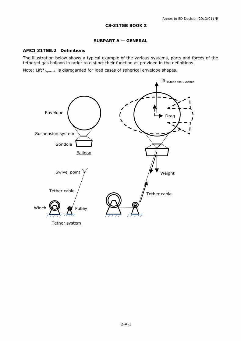
AMC1 31TGB.2 Definitions
The illustration below shows a typical example of the various systems, parts and forces of the
tethered gas balloon in order to distinct their function as provided in the definitions.
Note: Lift*Dynamic is disregarded for load cases of spherical envelope shapes.
Lift (Static and Dynamic)
Envelope
Suspension system
Gondola
Balloon
Swivel point
Tether cable
Winch Pulley
Tether cable
Weight
Drag
Tether system
Annex to ED Decision 2013/011/R
CS-31TGB BOOK 2
2-B-1
SUBPART B — FLIGHT
AMC1 31TGB.14 Mass limits
Maximum mass
The maximum mass results in a weight force that is equal or lower to the maximum static lift
force. The lift-producing medium is not part of the maximum mass.
For each structural loading case the maximum mass is established. The maximum mass
consists of the balloon and the length of the tether cable, which weight force acts upon the
balloon in the specific load case.
The maximum design mass of the product is the least of the maximum masses established for
the load cases or a lower maximum mass if so selected by the applicant.
Minimum mass
The minimum mass is the mass that results in the highest loading in the tether system under
the following conditions for which compliance to the structural requirements is shown:
Maximum deceleration during ascent
Maximum static lift
Maximal permissible wind speed of operation
Since the mass increases with the extension of the tether cable, the critical case for the
minimum mass is reached at the beginning of the ascent.
Mass limitations and information, e.g. pay load are established from the maximum and
minimum masses and provided in the Flight Manual.
AMC1 31TGB.20(b) Controllability
It is established by analysis that the hazards from the specified emergency conditions are
mitigated by design or procedures. Failure modes that can result in an unintended free flight of
the balloon with occupants are included in this analysis.
A suitable device (e.g. electronic altitude pressure switch combined with an ascent velocity
detector) ensuring that the envelope does not burst and a lifting gas valve is operated such
that a descent occurs in a manageable manner is regarded as acceptable.
A suitable procedure describes all necessary measures to be taken for the recovery.
If procedures for these emergency conditions are not covered by the normal operating
procedures they are included in the Flight Manual.
Annex to ED Decision 2013/011/R
CS-31TGB BOOK 2
2-C-1
SUBPART C — STRUCTURE
AMC1 31TGB.22 In-Service load cases
Inflation/mooring
The ‘inflation and mooring cases’ referred to in this requirement cover assembly, disassembly,
inflation, deflation and mooring load cases. Mooring load cases cover both low and high
mooring, if applicable.
When the balloon is moored in the parking position (low mooring) the maximum gas pressure
in the envelope is normally identical to the ‘maximum gas pressure’ established for any of the
flight conditions. If the low mooring operation, however, allows for a precautionary increased
pressure of the gas in the envelope this load case is also considered.
Flight
Flight load cases cover the operation within the established limitations (temperature, wind
speed, mass, and ascent/descent speed limitations). A dynamic lift component is considered in
the load cases for the sudden deceleration of the ascent/descent unit and when the envelope
shape is not spherical and generates lift in wind conditions. When a dynamic lift component is
applicable, gust loads are considered as well as potential oscillation behaviour of the balloon
and the tether caused by airflow and from variations in the lift component and its centre of
pressure.
AMC1 31TGB.23(b) Ascent load factors
The ascent load factor is applied to the static tether system load to cover dynamic loads to the
tether system resulting from decelerations during the ascent. The maximum deceleration
typically occurs when an emergency stop is made during maximum ascent speed. The highest
loads are typically experienced when this occurs at maximum static lift and minimum balloon
weight and minimum deceleration travel. Minimum balloon weight and minimum deceleration
travel coincide at low tether cable length when the mass of the tether cable is the lowest and
the elongation or slack of the tether cable are the lowest.
For an ascent speed below 1 m/sec, an ascent load factor of 2 is acceptable.
AMC1 31TGB.23(c) Gust load factor
A gust load factor is applicable to balloons that due to the shape of the envelope generate
aerodynamic lift forces in gust conditions. The gust load for spherical balloons is, therefore, 1
and is considered to have no influence on the loads.
AMC1 31TGB.25(b) Factors of safety
The dynamic loads on a balloon system are difficult to evaluate because metal or textile parts
behave quite different.
In absence of a more suitable method or as replacement of a load test, the failure of the load
bearing component shall be shown by the following method:
Multiply the limit load in the failing load path by two and distribute it as a static load among
the remaining load paths.
For conventional designs, this is an appropriate method which is based on good service
experience.
AMC1 31TGB.27(c) Strength and proof of strength
The envelope tests may be performed on representative portions of the envelope provided the
dimensions of these portions are sufficiently large to include critical design features and details

Annex to ED Decision 2013/011/R
CS-31TGB BOOK 2
2-C-2
such as critical seams, joints, load-attachment points, net mesh, etc. Also refer to
CS 31TGB.45 for specific tear propagation requirements.
AMC1 31TGB.27(e) Strength and proof of strength
The strength requirements need to include consideration of loads during transport, ground
handling and rigging. The loads need to be determined and the parts and components need to
be designed in accordance with their designated use and dimensioned such as not to fail under
recurrent loads.
Annex to ED Decision 2013/011/R
CS-31TGB BOOK 2
2-D-1
SUBPART D — DESIGN AND CONSTRUCTION
AMC1 31TGB.33(b) Materials
Approved specifications here are taken as being those produced by the applicant or those
meeting internationally recognised standards as defined applicable in the type design data.
Material specifications are those contained in documents accepted either specifically by the
Agency or by having been prepared by an organisation or person which the Agency accepts
has the necessary capabilities. In defining design properties, these material specification
values are modified and/or extended as necessary by the constructor to take account of
manufacturing practices (for example method of construction, forming, machining and
subsequent heat treatment). Also the effects of environmental conditions, such as temperature
and humidity expected in service, are taken into account.
AMC1 31TGB.35 Fabrication methods
Approved fabrication methods here are taken as being those produced by the applicant or
those meeting internationally recognised standards as defined in the applicable type design
data. Fabrication methods are those contained in documents accepted either specifically by the
Agency or by having been prepared by an organisation or person which the Agency accepts
has the necessary capabilities.
AMC1 31TGB.37(a) Fasteners
Approved specifications in the sense of these requirements are the standards described in the
AMC1 31TGB.33(b).
AMC1 31TGB.39 Protection of parts
Suspension system cables and components manufactured from stainless steels (corrosion
resistant steels) are considered compliant with this requirement.
To ensure the protection of parts, it is permissible to rely on recommended inspections (details
in the Maintenance Manual).
In cases where deterioration or loss of strength is unavoidable during the life of the product,
details of appropriate mandatory replacement lives or in-service testing are provided in the
maintenance programme (CS 31TGB.82).
AMC1 31TGB.45 Protection of envelope against tearing
Demonstration of sufficient rip-stopping capability of the envelope material.
The objective of this demonstration is to show that the envelope material is sufficiently
damage resistant. It therefore needs to be determined that the envelope material would not
continue to tear under the maximum tension and conditions (temperature) experienced in
normal operation.
In order to establish that the determined damage resistance is sufficient, the critical damage
should be reviewed in relation to local damage foreseeable in normal operation.
The local damages to be considered are:
existing damage that may be undetected during pre-flight inspection, and
limited damage, inflicted during flight where the size of the damage in itself would not
result in a catastrophic failure.
The resistance of envelope fabric to damage propagation is determined by test.
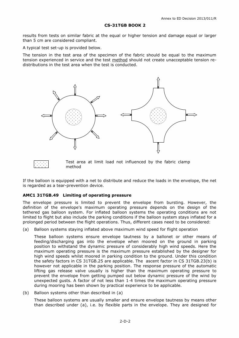
It is shown by test that a crosswise slit of at least 5 cm in the most unfavourable direction to
the envelope fabric at the maximum tension experienced in service does not propagate. Test
Annex to ED Decision 2013/011/R
CS-31TGB BOOK 2
2-D-2
results from tests on similar fabric at the equal or higher tension and damage equal or larger
than 5 cm are considered compliant.
A typical test set-up is provided below.
The tension in the test area of the specimen of the fabric should be equal to the maximum
tension experienced in service and the test method should not create unacceptable tension re-
distributions in the test area when the test is conducted.
If the balloon is equipped with a net to distribute and reduce the loads in the envelope, the net
is regarded as a tear-prevention device.
AMC1 31TGB.49 Limiting of operating pressure
The envelope pressure is limited to prevent the envelope from bursting. However, the
definition of the envelope's maximum operating pressure depends on the design of the
tethered gas balloon system. For inflated balloon systems the operating conditions are not
limited to flight but also include the parking conditions if the balloon system stays inflated for a
prolonged period between the flight operations. Thus, different cases need to be considered:
(a) Balloon systems staying inflated above maximum wind speed for flight operation
These balloon systems ensure envelope tautness by a ballonet or other means of
feeding/discharging gas into the envelope when moored on the ground in parking
position to withstand the dynamic pressure of considerably high wind speeds. Here the
maximum operating pressure is the maximum pressure established by the designer for
high wind speeds whilst moored in parking condition to the ground. Under this condition
the safety factors in CS 31TGB.25 are applicable. The ascent factor in CS 31TGB.23(b) is
however not applicable in the parking position. The response pressure of the automatic
lifting gas release valve usually is higher than the maximum operating pressure to
prevent the envelope from getting pumped out below dynamic pressure of the wind by
unexpected gusts. A factor of not less than 1·4 times the maximum operating pressure
during mooring has been shown by practical experience to be applicable.
(b) Balloon systems other than described in (a)
These balloon systems are usually smaller and ensure envelope tautness by means other
than described under (a), i.e. by flexible parts in the envelope. They are designed for
Test area at limit load not influenced by the fabric clamp
method
Annex to ED Decision 2013/011/R
CS-31TGB BOOK 2
2-D-3
maximum wind speed during flight operation and will normally be deflated during high
wind speed weather conditions. Here the maximum operating pressure is the pressure for
flight operation established by the designer. The response pressure of the automatic
lifting gas release device is not less than 1·15 times the maximum operating pressure.
For clarification, it should be noted that in a strict sense the automatic pressure release
device can only prevent the further rise of pressure for the very moment. After release
the device should close again in order to minimise the loss of lifting gas. If after a while
the pressure increases again for any reason, the device will also open again. This
behaviour is intended and does not impair safety.
AMC1 31TGB.51 Rapid deflation means
Rapid deflation means are used to deflate the envelope in cases like e.g. when:
wind speeds increase above the wind speed limitations for low mooring;
required during inflation before attachment of the tether cable; or
included in emergency procedures for unintended free flight.
Note: The rapid deflation means for low mooring acts automatically when the balloon is not
being monitored by an operator.
AMC1 31TGB.53(a) Tether system
The suitability, durability, and reliability of the tether system, including the tether control
systems, is determined by a Failure Mode Effect Analyses (FMEA) covering all phases of
operation.
For components of the tether system (i.e. the winch) compliance with the requirement of
CS 31TGB.53(a) can be shown by a certificate from an expert body provided that:
(a) this certificate specifies the conditions for safe operation of the winch that cover the conditions for safe operation of the balloon;
(b) the winch system is capable of safely fulfilling the task of a tethered gas balloon winch;
(c) compliance with the Machinery Directive 2006/42/EC (or equivalent (US) requirements) is the basis for the tethered gas balloon winch system;
(d) modifications to the winch design do not invalidate the applicable requirements from the certificate that remain applicable after the modification.
Note: The overload protection of industrial winches is not applicable in the TGB
application because overload cannot occur in a TGB application;
(e) the expert body is an EC-notified organisation which has a certified structure and a proven capability and experience. ‘Certified’ means an approval by the government which requires an organisational structure and entails extended liability. ‘Proven capability’ means successfully managed projects that are reasonably comparable to the balloon winch case. Usually these are cranes, elevators, rides or similar winch technology;
(f) the final report complies with the Annex II of the Machinery Directive 2006/42/EC (or equivalent (US) requirement); and
(g) there is an alternative retrieve system which is able to cover a functional failure of the winch.
AMC1 31TGB.53(c) Tether system
An automatic rapid deflation (See CS 31TGB.51) of the balloon in case it breaks away from its
low mooring position or any other system that will prevent uncontrolled free flight is an
acceptable risk mitigation.
Annex to ED Decision 2013/011/R
CS-31TGB BOOK 2
2-D-4
AMC1 31TGB.59 Gondola
The requirements for a gondola carrying multiple free-standing persons is complied with when
the applicable requirements for the ‘carrier’ provided in the Machinery Directive 2006/42/EC
are met.
AMC1 31TGB.59(c) Gondola
A holding grip provides an obvious means for the occupants of the gondola to stabilise
themselves during flight. The location or design of occupant securing devices (refer to
CS 31TGB.59(f)(1)) is such that they do not invite occupants to use them as holding grip.
AMC1 31TGB.59(d) Gondola
For gondola providing standing space for the occupant, a minimum plan area of 0·3 m² is
provided for each occupant.
AMC1 31TGB.65(a) Night lighting
A means to provide illumination of the instruments, equipment and controls that are essential
for the safe operation of the balloon may be instrument lighting, local lighting or any
independent portable (non-handheld) light of sufficient capacity.
It is acceptable that lights can be switch on and off provided that the operator, without undue
burden or ambiguity, can switch on the lighting in night conditions.
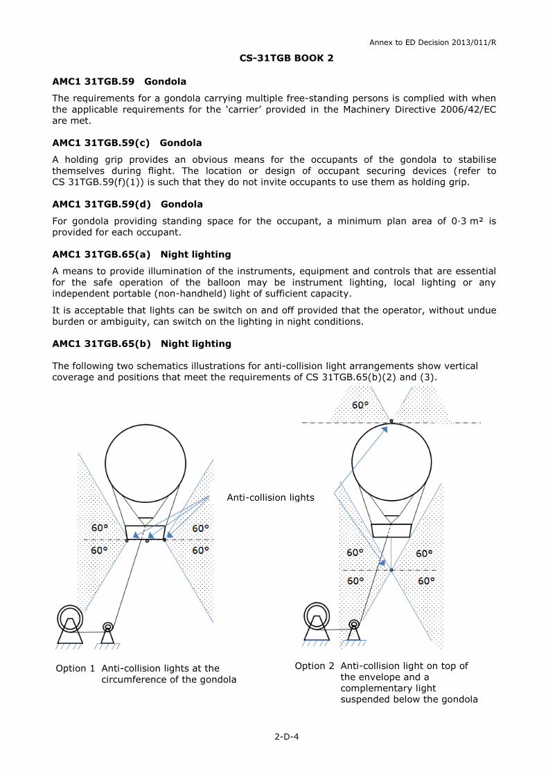
AMC1 31TGB.65(b) Night lighting
The following two schematics illustrations for anti-collision light arrangements show vertical
coverage and positions that meet the requirements of CS 31TGB.65(b)(2) and (3).
Anti-collision lights
Option 1 Anti-collision lights at the
circumference of the gondola
Option 2 Anti-collision light on top of
the envelope and a
complementary light suspended below the gondola
Annex to ED Decision 2013/011/R
CS-31TGB BOOK 2
2-D-5
The horizontal 360° coverage requirement is applicable to a distance between 100 m and
3 700 m (2 NM). It is acceptable that the light from the anti-collision lights is not visible from
positions closer than 100 m horizontally from the balloon.
AMC1 31TGB.65(c) Night lighting
The light from the Anti-Collision light does not directly shine on the crew and passengers and
does not create a reflection on the balloon or flare that disturbs the crews’ performance.
Lighting level of controls, equipment and instruments are compatible with the crew night
vision. This prevents untimely fatigue of the eyesight due to frequent adaptation when looking
from bright light into dark night and vice versa.
AMC1 31TGB.67 On-board power units
For this AMC, it is assumed that only power units are used which conform to the state-of-the-
art industrial standard. The safe operation of the balloon is not directly dependent on the
proper function of the power unit. For all other designs, the Agency is consulted for more
detailed requirements.
Power units of industrial standard used on-board of the balloon in addition comply with the
following:
(a) General
The power unit is designed and installed so that under all normal operating conditions
and reasonably foreseeable in service emergency situations, it does not endanger the
aircraft, its occupants, or third parties.
(b) Ventilation
The occupants are accommodated in adequately ventilated areas where:
(1) the carbon monoxide partial pressure does not exceed 1/20 000; and
(2) fuel vapour is not present in harmful concentrations.
(c) Fire extinguishers
(1) Unless the power unit has a fire extinguishing system by itself, there is at least one manual fire extinguisher within reach of an occupant.
(2) The following applies to manual fire extinguishers. The type and quantity of the fire extinguishing substance is appropriate to the fire extinguisher's application area. Fire extinguishers:
(i) conform to EN3 or an equivalent specification acceptable to the Agency;
(ii) have a minimum capacity of 2 kg when using dry powder, unless the capacity
is otherwise determined by the applicant; and
(iii) be at least of comparable effect when the extinguishing means is other than
‘dry powder’.
(3) Fire extinguishers in compartments intended for persons are designed to minimise the risk of toxicity caused by use of the fire extinguishing substance.
(d) Gondola
The following applies to the gondola when an on-board power unit is carried:
(1) The material used is at least fire retardant.
(2) Pipes, tanks or equipment that carries fuel, oil or flammable liquids are not to be placed in the gondola unless they are reasonably shielded, insulated, or otherwise protected so that fracture or failure of such parts causes no danger.
Annex to ED Decision 2013/011/R
CS-31TGB BOOK 2
2-D-4
(e) Electrical earth connection
(1) In order to prevent the occurrence of potential differences between components of the power unit and other electrically conductive parts of the balloon which cannot be ignored on account of their mass, such conductive parts are conductively interconnected.
(2) The cross-sectional area of bonding connectors, if made from copper, is not less than 1·33 mm².
(f) Fire protection for control system and structure
Control systems, suspension units or other structures in the power unit compartment
which are added to the design by the applicant are made of fireproof material or shielded
to withstand the effect of a fire.
(g) Fire protection
(1) The power unit is adequately separated from the balloon's structure by fireproof bulkheads or ventilated bays.
(2) Areas in which combustible liquids can accumulate as a result of a leaking tank have an adequate drain pipe. Collected leaking liquids cannot reach other locations in and under the craft which pose a potential risk of fire.
(3) Precautionary measures are to be taken to reduce as far as possible the risk of fire as a result of a hard landing of the gondola.
(h) Power unit installation
(1) Each power unit is supported so that the loads resulting from the weight of the unit are not concentrated.
(2) There are pads, if necessary, to prevent chafing between each unit and its supports.
(3) Materials employed for supporting the unit or padding the supporting members are non-absorbent or treated to prevent the absorption of fuel.
(4) Each installation is ventilated and drained to prevent accumulation of flammable fluids and vapours.
(i) Fuel tank expansion space
(1) Each external fuel tank added to the design by the applicant has an expansion space of sufficient capacity, but of not less than 2 % of the tank capacity, to prevent spillage of fuel onto the surfaces of the power unit and the balloon's structure due to thermal expansion or manoeuvre unless the design of the venting system precludes such spillage.
(2) It is not possible to fill the expansion space inadvertently with the power unit in any normal ground attitude.
(j) Exhaust system, general
(1) The exhaust system ensures safe disposal of exhaust gases without fire hazard or carbon monoxide contamination in any personnel compartment.
(2) Each exhaust system part with a surface hot enough to ignite flammable fluids or vapours is located or shielded so that leakage from any system carrying flammable fluids or vapours will not result in a fire caused by impingement of the fluids or vapours on any part of the exhaust system, including shields for the exhaust system.
(3) All parts of the exhaust system are located sufficiently far from or separated from adjacent parts of the balloon's structure by fireproof shielding.
(4) No exhaust gases will discharge dangerously near any oil or fuel system drain.
Annex to ED Decision 2013/011/R
CS-31TGB BOOK 2
2-D-5
(5) Each exhaust system component added to the design by the applicant is ventilated to prevent points of excessively high temperature.
(k) Firewalls
(1) The power unit is isolated from the rest of the balloons structure by a firewall, shroud, or equivalent means.
(2) The firewall or shroud is constructed so that no hazardous quantity of liquid, gas or flame can pass from the power unit compartment to other parts of the balloon.
(3) The firewall and shroud is fireproof and protected against corrosion or deterioration. The following materials are accepted as fireproof, when used in firewalls or shrouds, without being tested:
(i) stainless steel sheet, 0·38 mm thick;
(ii) mild steel sheet (coated with aluminium or otherwise protected against corrosion) 0·5 mm thick;
(iii) steel or copper base alloy firewall fittings.
(4) Other materials such as fire protection paint and/or putty are only used if they conform to the FAA Advisory Circular No. 20-135 or equivalent accepted specifications.
AMC1 31TGB.69(c) Electric cables and equipment
The risk of short circuit for the electrical cable between battery and master switch is minimised
when the unprotected battery to master switch cables, of an adequate capacity, have a
maximum length of 0·5 m.
In any event the capacities of protected cables are such that no hazardous damage will occur
to the balloon and its occupants, nor its effects to the occupants from the generation of
noxious fumes, due to electrical overloading of cables before a circuit protective device will
operate.
Annex to ED Decision 2013/011/R
CS-31TGB BOOK 2
2-F-1
SUBPART F — SYSTEMS AND EQUIPMENT
AMC1 31TGB.71(c) Function and installation
An instrument, in the classical sense, houses the sensor and the indicator (e.g. altimeter).
However, it should be noted that for tethered gas balloons the sensor and the indicating
display may be mounted far away from each other (e.g. sensor on the top; display in the
gondola or at the winch). Hence, the word ‘instrument’ may not necessarily mean an
integrated system.
The 'most appropriate place' for the instruments required by subparagraph CS 31TGB.71(c)(2)
and (c)(3) shall be established in view of accuracy for measuring the values.
AMC1 31TGB.71(d) Function and installation
The correct functioning is not to be impaired by icing, heavy rain, high humidity, or low and
high temperatures.
When ATC equipment is installed, it is shown that the electrical system is such that the
operation of this equipment is not adversely affected.
The operating instructions provide information regarding systems and equipment essential for
safe operation. Restrictions or mitigating actions for inoperative systems or equipment are
included in the operating instructions to support continued safe operation if applicable.
Annex to ED Decision 2013/011/R
CS-31TGB BOOK 2
2-G-1
SUBPART G — OPERATING LIMITS AND DETAILS
AMC1 31TGB.81(b)(5) Flight Manual
Site preparation and installation information
(a) The site preparation instructions include:
(1) the magnitudes and x-, y- and z-directions of each load carrying interface between the tether system and the ground;
(2) dimensions and categories of safety areas on the ground and in the air;
(3) the ground condition and its permitted maximum mean slope; and
(4) any additional safety area required by the emergency descent procedure, if applicable.
(b) The installation information includes:
(1) a list of the minimum installation crew and their necessary skills;
(2) a checklist of the necessary tools and devices for installing/de-installing; and
(3) a checklist describing the necessary sequential steps for installation/de-installation. The list highlights the safety critical phases including precautions and mitigating measures.
AMC1 31TGB.82 Instructions for continued airworthiness
Note: The paragraph numbering of this AMC relates to the paragraph numbering of CS
31TGB.82
(c) If instructions for continued airworthiness are not supplied by the manufacturer or designer of parts and appliances installed in the balloon, the instructions for continued airworthiness for the balloon need to include the information essential to the continued airworthiness of the balloon.
If manuals from different manufacturers are used, they need to provide a practical
arrangement.
(d)(1) The detailed description of the balloon and its components needs to include for each balloon:
(1) a description of the systems including the assembly and disassembly instructions;
(2) a parts list covering all construction and equipment components and the assemblies. Where applicable, individual parts need to be numbered so that they can be related to the different assemblies and that their number corresponds to the type plate of the assembly; and
(3) a summary of the materials and consumables used with procurement details.
Annex to ED Decision 2013/011/R
CS-31TGB BOOK 2
2-G-2
(d)(5) If applicable, the maintenance schedule may include instructions for continued airworthiness (e.g. recommended inspections or mandatory replacement of parts) to ensure the suitable protection of parts against deterioration or loss of strength, objective pass or fail criteria, e.g. applicable where tolerances need to be provided.
(d)(6) The maintenance and inspection instructions need to provide information for removal and installation, cleaning, inspecting, adjusting, testing and lubrication of systems, parts and appliances of the balloon as required for continued airworthiness. Reference may be made to information from an accessory, instrument or equipment manufacturer as the source of this information if it is shown that the item has an exceptionally high degree of complexity requiring specialised maintenance techniques, test equipment or expertise.
(d)(9) If the instructions for continued airworthiness consist of multiple documents, the Airworthiness Limitations section needs to be included in the principal manual.
AMC1 31TGB.83 Crew training and training information
The crew training and training information contains the following aspects when applicable to
the operation of the balloon:
(a) general information on the training syllabus (theoretical and practical training) and examination;
(b) description of the system in sufficient detail to understand the principles of the balloon and systems;
(c) environmental conditions and their impact on safe operation;
(d) procedures for:
(1) mooring (high and low);
(2) flying;
(3) inflation and deflation; and
(4) emergency procedures;
(e) weather;
(f) maintenance; and
(g) record keeping.