Embed Size (px)
Citation preview
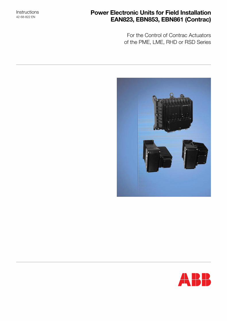
Instructions42�68�822 EN
Power Electronic Units for Field InstallationEAN823, EBN853, EBN861 (Contrac)
For the Control of Contrac Actuatorsof the PME, LME, RHD or RSD Series
2
ContentDevice Identification . . . . . . . . . . . . . . . . . . . . . . . . . 2
Application . . . . . . . . . . . . . . . . . . . . . . . . . . . . . . . . 3
General . . . . . . . . . . . . . . . . . . . . . . . . . . . . . . . . . . . 3Proper Use . . . . . . . . . . . . . . . . . . . . . . . . . . . . . . . . 3Safety and Precautions . . . . . . . . . . . . . . . . . . . . . . . . 3
Storage . . . . . . . . . . . . . . . . . . . . . . . . . . . . . . . . . . . 3Long-time Storage . . . . . . . . . . . . . . . . . . . . . . . . . . . 3
Delivery settings . . . . . . . . . . . . . . . . . . . . . . . . . . . . 3
Assemblies . . . . . . . . . . . . . . . . . . . . . . . . . . . . . . . . 4EAN823 / EBN853 . . . . . . . . . . . . . . . . . . . . . . . . . . . 4EBN861 . . . . . . . . . . . . . . . . . . . . . . . . . . . . . . . . . . 5
Technical Data . . . . . . . . . . . . . . . . . . . . . . . . . . . . . 6General . . . . . . . . . . . . . . . . . . . . . . . . . . . . . . . . . . . 6Current Consumption of EAN823 . . . . . . . . . . . . . . . . . 6Current Consumption of EBN853 . . . . . . . . . . . . . . . . . 7Current consumption of EBN861 . . . . . . . . . . . . . . . . . . 7Fuses . . . . . . . . . . . . . . . . . . . . . . . . . . . . . . . . . . . . 7
Mounting . . . . . . . . . . . . . . . . . . . . . . . . . . . . . . . . . . 8Preparing the electronics . . . . . . . . . . . . . . . . . . . . . . . 8Mounting of EAN823 / EBN853 . . . . . . . . . . . . . . . . . . . 8Mounting of EBN861 . . . . . . . . . . . . . . . . . . . . . . . . . . 8
Electrical connection . . . . . . . . . . . . . . . . . . . . . . . . . 9EAN823 / EBN853 / EBN861 (Standard) . . . . . . . . . . . . . 9EAN823 / EBN851 / EBN861 (PROFIBUS DP) . . . . . . . . . 9Connecting the cable shield . . . . . . . . . . . . . . . . . . . . 10Example for signal input / output . . . . . . . . . . . . . . . . . 10Cable guidance at the plug . . . . . . . . . . . . . . . . . . . . 11
Setup . . . . . . . . . . . . . . . . . . . . . . . . . . . . . . . . . . . . 12Set-up via local control panel (LCP) . . . . . . . . . . . . . . . 12Adjustment using the configuration program . . . . . . . . . 13Functions and signals at the LCP . . . . . . . . . . . . . . . . 13
Alarms / Failures . . . . . . . . . . . . . . . . . . . . . . . . . . . 15Definition . . . . . . . . . . . . . . . . . . . . . . . . . . . . . . . . 15Alarm scheme . . . . . . . . . . . . . . . . . . . . . . . . . . . . . 15Failure scheme . . . . . . . . . . . . . . . . . . . . . . . . . . . . . 16
Troubleshooting . . . . . . . . . . . . . . . . . . . . . . . . . . . 17
Legend
1. Device Identification
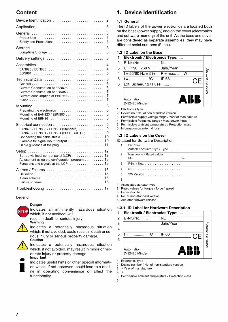
1.1 GeneralThe ID labels of the power electronics are located bothon the base (power supply) and on the cover (electronicsand software memory) of the unit. As the base and coverare considered as separate assemblies, they may havedifferent serial numbers (F. no.).
1.2 ID Label on the Base
1. Electronics type2. Device no./ No. of non-standard version3. Permissible supply voltage range / Year of manufacture4. Permissible frequency range / Max. power input5. Permissible ambient temperature / Protection class6. Information on external fuse
1.3 ID Labels on the CoverID Label for Software Description
1 Associated actuator type 2 Rated values for torque / force / speed3 Fabrication No.4 No. of non-standard version5 Actuator firmware release
1.3.1 ID Label for Hardware Description
1. Electronics type2. Device number / No. of non-standard version3. / Year of manufacture4. / 5. Permissible ambient temperature / Protection class6.
DangerIndicates an imminently hazardous situationwhich, if not avoided, willresult in death or serious injuryWarningIndicates a potentially hazardous situationwhich, if not avoided, could result in death or se-rious injury or serious property damage.CautionIndicates a potentially hazardous situationwhich, if not avoided, may result in minor or mo-derate injury or property damage.ImportantIndicates useful hints or other special informati-on which, if not observed, could lead to a decli-ne in operating convenience or affect thefunctionality.
1 Elektronik / Electronics Type: ....
Mad
e in
Ger
man
y
2 B-Nr./No. ...... NL3 U = 190...260 V ... Jahr/Year4 f = 50/60 Hz ± 5% P = max. ..... W5 t = ..................°C IP 66 CE6 Ext. Sicherung / Fuse .......
AutomationD-32425 Minden
1 Für / For Antrieb / Actuator Typ / Type . . . . . . . .
2 Nennwerte / Rated valuesM=....... .......°/s
3 F-Nr. / No.: . . . . . . . . . . . . . . . . . . . . . .
4 NL . . . . . . . . . . . . . . . . . . . . . . . . . . . . .
5 SW Version . . . . . . . . . . . . . . . . . . . . .
6
1 Elektronik / Electronics Type: ....
Mad
e in
Ger
man
y
2 B-Nr./No. ...... NL3 Jahr/Year45 t = ..................°C IP 66 CE6
AutomationD-32425 Minden

2. ApplicationUse this instruction only together with the actuator instruction.
3. General3.1 Proper UsePower electronics models EAN823, EBN853 and EBN861 are to be used exlusively for triggering elek-trical actuators of the PME120, LME 620, RSD... or RHD... series. Do not use them for any other pur-pose. Otherwise, a hazard of personal injury or of damage to or impairment of the operational reliabilityof the device may arise.
3.2 Safety and PrecautionsWhen mounting the electronics in areas which may be accessed by unauthorized persons, take the re-quired protective measures. - Only qualified specialists who have been trained for these tasks are authorized to mount and adjust
the electronics, and to make the electrical connection. - When working on the electronics always observe the locally valid accident prevention regulations
and the regulations concerning the construction of technical installations. - Switch-off the voltage supply; make sure that unintentional switching on is not possible- Make sure that cutting off the voltage supply does not affect the plant process- Consider restoring process forces from the final control element when cutting off the voltage
4. StorageThe devices may be stored under moist and aggressive condition for a short time. The equipment isprotected against external corrosive influences. However, direct exposure to rain, snow, etc. must beavoidedCondensation may occur in the terminal box. Therefore, it is protected by a desiccant, which ensuressufficient protection for approximately 150 days. The desiccant can be regenerated at a temperature of90° C within 4 h.The desiccant must be removed prior to commissioning the electronics.
4.1 Long-time StorageIf you intend to store or transport the device for a longer time, we recommend to wrap it in plastic foiland add desiccant. Regularly check if the desiccant is still active.
5. Delivery settingsBehavior in 0/100% position: Keep closed with rated torqueSetpoint function: Linear; setpoint = positioning valueInput (setpoint): 4 ... 20 mA 1)
Function: Positioner, parameter: setpointOutput (actual value): 4 ... 20 mA 1)
Digital inputs: 1) DI 1 switch-over manual/automatic and v.v.DI 2 / DI 3 manual control +/-
Digital outputs: 1) DO 1 ready to operate, DO 2/3 end position signalling Range: Not adjusted (to be adjusted during commissioning)
The configuration of your actuator may differ from the standard configuration specified above. It can becalled up for display using a notebook / PC and the related configuration program.
1) not with fieldbus communication.
3
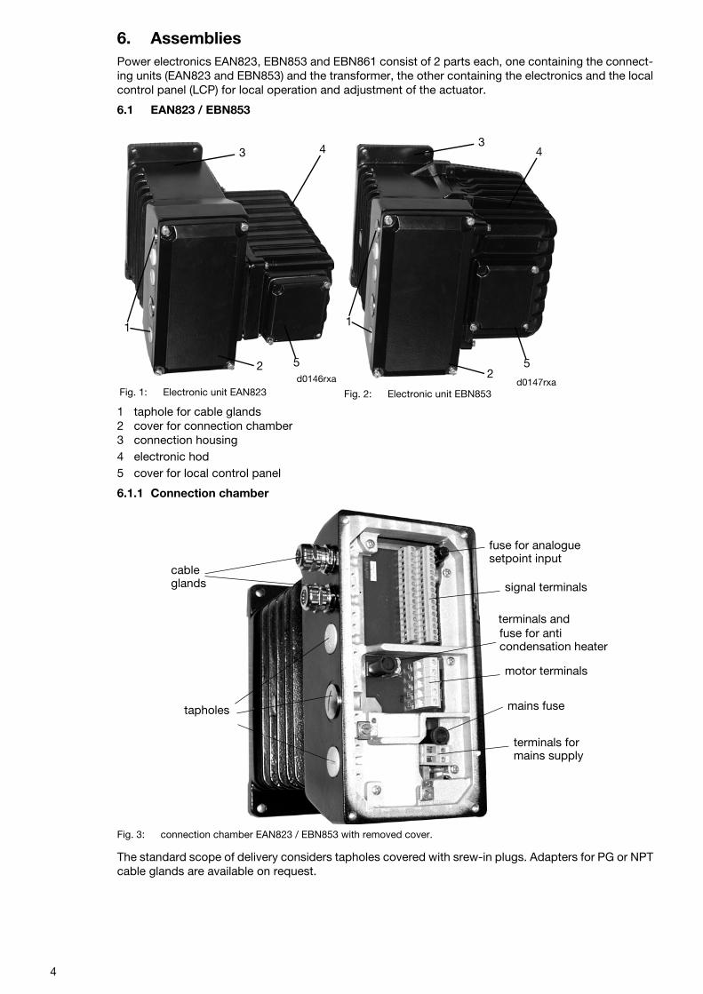
6. AssembliesPower electronics EAN823, EBN853 and EBN861 consist of 2 parts each, one containing the connect-ing units (EAN823 and EBN853) and the transformer, the other containing the electronics and the localcontrol panel (LCP) for local operation and adjustment of the actuator.
6.1 EAN823 / EBN853
1 taphole for cable glands2 cover for connection chamber3 connection housing4 electronic hod5 cover for local control panel
6.1.1 Connection chamber
Fig. 3: connection chamber EAN823 / EBN853 with removed cover.
The standard scope of delivery considers tapholes covered with srew-in plugs. Adapters for PG or NPTcable glands are available on request.
Fig. 1: Electronic unit EAN823 Fig. 2: Electronic unit EBN853
1
2 5
43
d0146rxa
34
52
1
d0147rxa
tapholes
signal terminals
motor terminals
terminals for
mains fuse
fuse for anti
fuse for analogue setpoint input
cable
condensation heater
mains supply
glands
terminals and
4
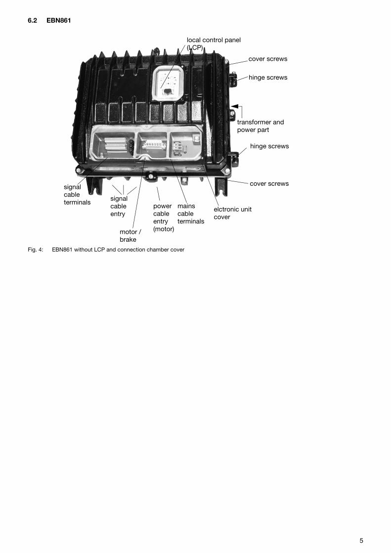
6.2 EBN861
Fig. 4: EBN861 without LCP and connection chamber cover
mains signal
transformer and
elctronic unit
hinge screws
cover screwssignal
motor /
cablepower cableentry(motor)
cable
brake
entry
cable
cover
power part
hinge screws
cover screws
local control panel(LCP)
terminals
terminals
5
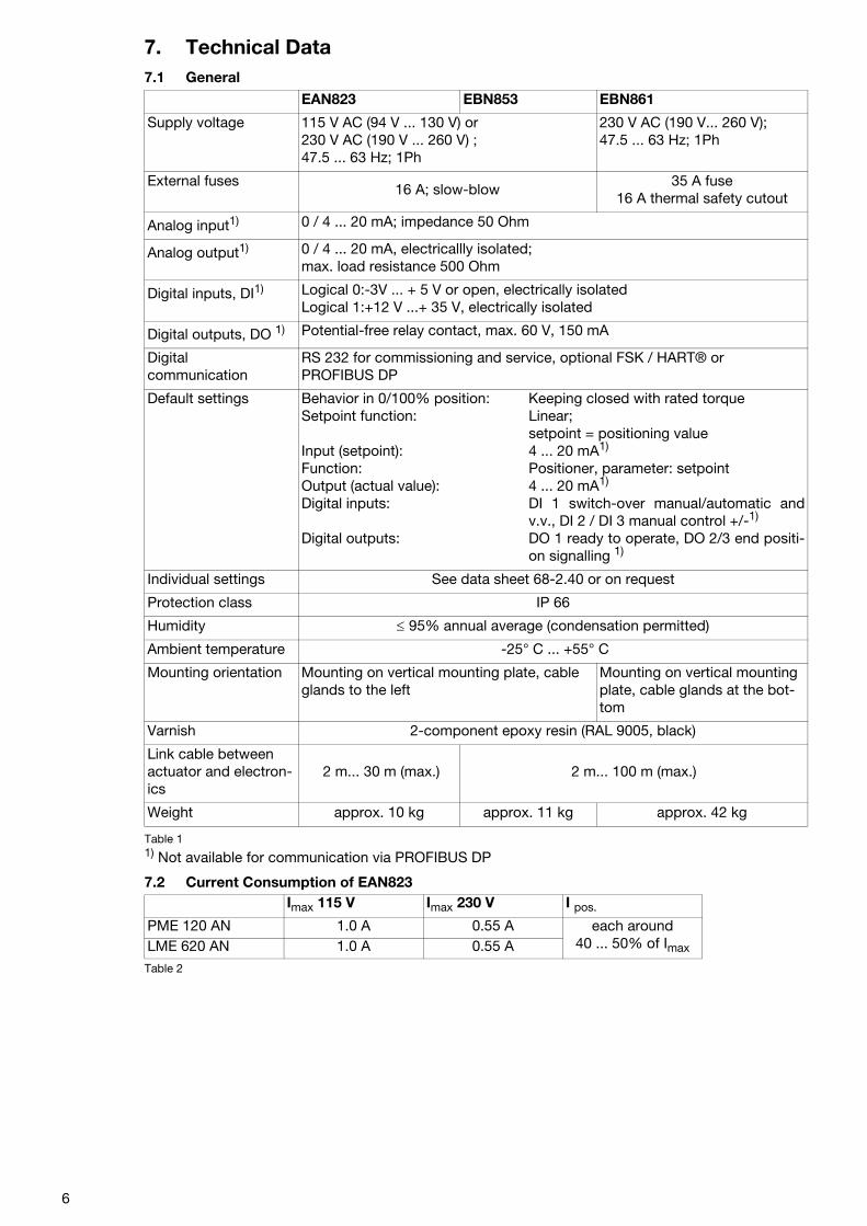
7. Technical Data7.1 General
1) Not available for communication via PROFIBUS DP
7.2 Current Consumption of EAN823
Table 2
EAN823 EBN853 EBN861
Supply voltage 115 V AC (94 V ... 130 V) or 230 V AC (190 V ... 260 V) ; 47.5 ... 63 Hz; 1Ph
230 V AC (190 V... 260 V); 47.5 ... 63 Hz; 1Ph
External fuses16 A; slow-blow
35 A fuse16 A thermal safety cutout
Analog input1) 0 / 4 ... 20 mA; impedance 50 Ohm
Analog output1) 0 / 4 ... 20 mA, electricallly isolated; max. load resistance 500 Ohm
Digital inputs, DI1) Logical 0:-3V ... + 5 V or open, electrically isolatedLogical 1:+12 V ...+ 35 V, electrically isolated
Digital outputs, DO 1) Potential-free relay contact, max. 60 V, 150 mA
Digital communication
RS 232 for commissioning and service, optional FSK / HART® or PROFIBUS DP
Default settings Behavior in 0/100% position: Keeping closed with rated torqueSetpoint function: Linear;
setpoint = positioning valueInput (setpoint): 4 ... 20 mA1)
Function: Positioner, parameter: setpointOutput (actual value): 4 ... 20 mA1)
Digital inputs: DI 1 switch-over manual/automatic andv.v., DI 2 / DI 3 manual control +/-1)
Digital outputs: DO 1 ready to operate, DO 2/3 end positi-on signalling 1)
Individual settings See data sheet 68-2.40 or on request
Protection class IP 66
Humidity ≤ 95% annual average (condensation permitted)
Ambient temperature -25° C ... +55° C
Mounting orientation Mounting on vertical mounting plate, cable glands to the left
Mounting on vertical mounting plate, cable glands at the bot-tom
Varnish 2-component epoxy resin (RAL 9005, black)
Link cable between actuator and electron-ics
2 m... 30 m (max.) 2 m... 100 m (max.)
Weight approx. 10 kg approx. 11 kg approx. 42 kg
Table 1
Imax 115 V Imax 230 V I pos.
PME 120 AN 1.0 A 0.55 A each around40 ... 50% of ImaxLME 620 AN 1.0 A 0.55 A
6
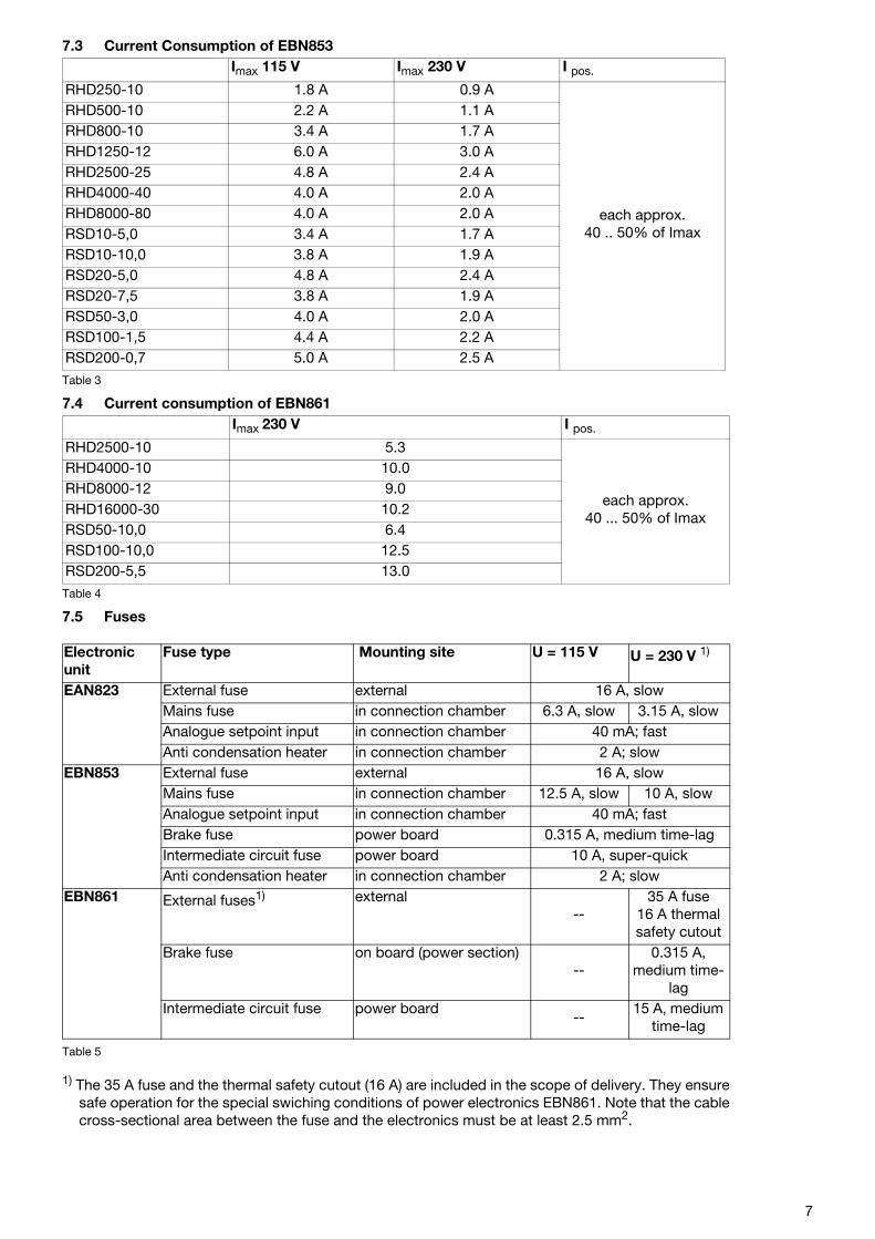
7.3 Current Consumption of EBN853
Table 3
7.4 Current consumption of EBN861
Table 4
7.5 Fuses
1) The 35 A fuse and the thermal safety cutout (16 A) are included in the scope of delivery. They ensuresafe operation for the special swiching conditions of power electronics EBN861. Note that the cablecross-sectional area between the fuse and the electronics must be at least 2.5 mm2.
Imax 115 V Imax 230 V I pos.
RHD250-10 1.8 A 0.9 A
each approx. 40 .. 50% of Imax
RHD500-10 2.2 A 1.1 ARHD800-10 3.4 A 1.7 ARHD1250-12 6.0 A 3.0 ARHD2500-25 4.8 A 2.4 ARHD4000-40 4.0 A 2.0 ARHD8000-80 4.0 A 2.0 ARSD10-5,0 3.4 A 1.7 ARSD10-10,0 3.8 A 1.9 ARSD20-5,0 4.8 A 2.4 ARSD20-7,5 3.8 A 1.9 ARSD50-3,0 4.0 A 2.0 ARSD100-1,5 4.4 A 2.2 ARSD200-0,7 5.0 A 2.5 A
Imax 230 V I pos.
RHD2500-10 5.3
each approx. 40 ... 50% of Imax
RHD4000-10 10.0RHD8000-12 9.0RHD16000-30 10.2RSD50-10,0 6.4RSD100-10,0 12.5RSD200-5,5 13.0
Electronic unit
Fuse type Mounting site U = 115 V U = 230 V 1)
EAN823 External fuse external 16 A, slowMains fuse in connection chamber 6.3 A, slow 3.15 A, slowAnalogue setpoint input in connection chamber 40 mA; fastAnti condensation heater in connection chamber 2 A; slow
EBN853 External fuse external 16 A, slowMains fuse in connection chamber 12.5 A, slow 10 A, slowAnalogue setpoint input in connection chamber 40 mA; fastBrake fuse power board 0.315 A, medium time-lagIntermediate circuit fuse power board 10 A, super-quickAnti condensation heater in connection chamber 2 A; slow
EBN861 External fuses1) external--
35 A fuse16 A thermal safety cutout
Brake fuse on board (power section)--
0.315 A, medium time-
lagIntermediate circuit fuse power board
--15 A, medium
time-lag
Table 5
7
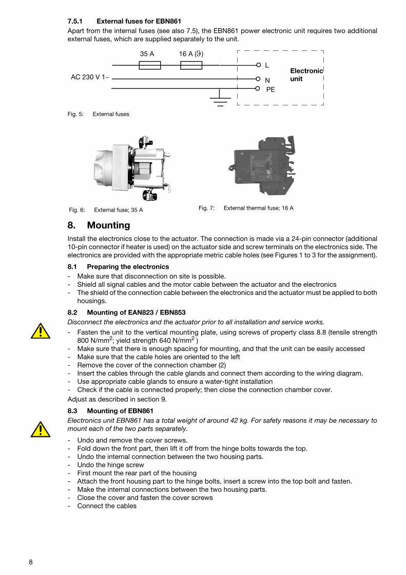
7.5.1 External fuses for EBN861Apart from the internal fuses (see also 7.5), the EBN861 power electronic unit requires two additionalexternal fuses, which are supplied separately to the unit.
Fig. 5: External fuses
8. MountingInstall the electronics close to the actuator. The connection is made via a 24-pin connector (additional10-pin connector if heater is used) on the actuator side and screw terminals on the electronics side. Theelectronics are provided with the appropriate metric cable holes (see Figures 1 to 3 for the assignment).
8.1 Preparing the electronics- Make sure that disconnection on site is possible.- Shield all signal cables and the motor cable between the actuator and the electronics - The shield of the connection cable between the electronics and the actuator must be applied to both
housings.
8.2 Mounting of EAN823 / EBN853Disconnect the electronics and the actuator prior to all installation and service works.
- Fasten the unit to the vertical mounting plate, using screws of property class 8.8 (tensile strength800 N/mm2; yield strength 640 N/mm2 )
- Make sure that there is enough spacing for mounting, and that the unit can be easily accessed- Make sure that the cable holes are oriented to the left- Remove the cover of the connection chamber (2) - Insert the cables through the cable glands and connect them according to the wiring diagram.- Use appropriate cable glands to ensure a water-tight installation- Check if the cable is connected properly; then close the connection chamber cover. Adjust as described in section 9.
8.3 Mounting of EBN861Electronics unit EBN861 has a total weight of around 42 kg. For safety reasons it may be necessary tomount each of the two parts separately.
- Undo and remove the cover screws.- Fold down the front part, then lift it off from the hinge bolts towards the top.- Undo the internal connection between the two housing parts.- Undo the hinge screw- First mount the rear part of the housing- Attach the front housing part to the hinge bolts, insert a screw into the top bolt and fasten. - Make the internal connections between the two housing parts. - Close the cover and fasten the cover screws- Connect the cables
Fig. 6: External fuse; 35 A Fig. 7: External thermal fuse; 16 A
L
AC 230 V 1~
16 A (ϑ)35 A
NPE
Electronic unit
8
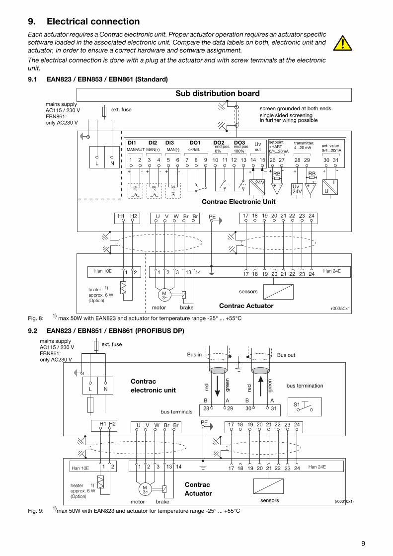
9. Electrical connectionEach actuator requires a Contrac electronic unit. Proper actuator operation requires an actuator specific software loaded in the associated electronic unit. Compare the data labels on both, electronic unit and actuator, in order to ensure a correct hardware and software assignment.
The electrical connection is done with a plug at the actuator and with screw terminals at the electronic unit.
9.1 EAN823 / EBN853 / EBN861 (Standard)
Fig. 8: 1) max 50W with EAN823 and actuator for temperature range -25° ... +55°C
9.2 EAN823 / EBN851 / EBN861 (PROFIBUS DP)
Fig. 9: 1)max 50W with EAN823 and actuator for temperature range -25° ... +55°C
24V
Uv
30
+ - -+
RB
+ -
31
I
U
26 271
+ - + - + - + -
72 83 94 10 135 11 146 12 15L N
Uv
24V
+
RB
+ -
28 29
17 18 19 20 21 22 23 24
17 18 19 20 21 22 23 24
U V W Br Br
1 21 2 3 13 14
M
3~
H1 H2 PE
single sided screeningin further wiring possible
r00350x1
Sub distribution board
screen grounded at both ends
Contrac Electronic Unit
Contrac Actuator
sensors
motor brake
heaterapprox. 6 W(Option)
Han 10E Han 24E
MAN/AUT MAN(+) MAN(-) ok/fail.end pos. end pos
out
setpoint+HART0/4...20mA
transmitter.4...20 mA act. value
0/4...20mA
mains supplyAC115 / 230 VEBN861: only AC230 V
ext. fuse
1)
0% 100%
DI1 DI2 DI3 DO1 DO2 DO3
L N
Bus outBus in
28 29 30
B BA A
31S1
17 18 19 20 21 22 23 24U V W BrH1 BrH2
17 18 19 20 21 22 23 241 2 3 13 14
M
3~
PE
1 2
(r00010x1)
Contracelectronic unit
ContracActuator
red
gree
n
bus termination
motor brake sensors
bus terminals
Han 10E
mains supplyAC115 / 230 VEBN861: only AC230 V
ext. fuse
Han 24E
1)
red
gree
n
heaterapprox. 6 W(Option)
9
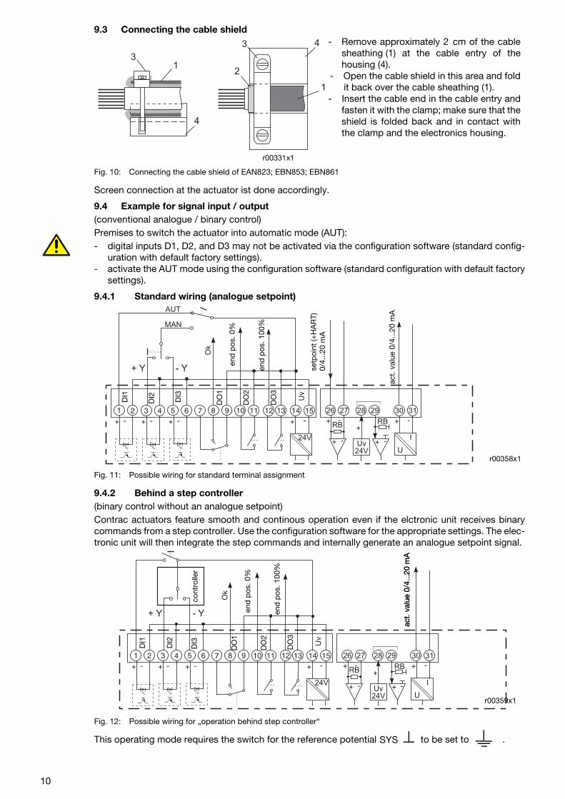
9.3 Connecting the cable shield
Fig. 10: Connecting the cable shield of EAN823; EBN853; EBN861
Screen connection at the actuator ist done accordingly.
9.4 Example for signal input / output(conventional analogue / binary control)Premises to switch the actuator into automatic mode (AUT):- digital inputs D1, D2, and D3 may not be activated via the configuration software (standard config-
uration with default factory settings).- activate the AUT mode using the configuration software (standard configuration with default factory
settings).
9.4.1 Standard wiring (analogue setpoint)
Fig. 11: Possible wiring for standard terminal assignment
9.4.2 Behind a step controller(binary control without an analogue setpoint)Contrac actuators feature smooth and continous operation even if the elctronic unit receives binarycommands from a step controller. Use the configuration software for the appropriate settings. The elec-tronic unit will then integrate the step commands and internally generate an analogue setpoint signal.
Fig. 12: Possible wiring for „operation behind step controller“
This operating mode requires the switch for the reference potential to be set to .
1
1
2
4
4
3
3 - Remove approximately 2 cm of the cablesheathing (1) at the cable entry of thehousing (4).
- Open the cable shield in this area and foldit back over the cable sheathing (1).
- Insert the cable end in the cable entry andfasten it with the clamp; make sure that theshield is folded back and in contact withthe clamp and the electronics housing.
r00331x1
Uv
24V
24V
+ -- -+
+
RBRB
+ -+ -I
U
Uv
+ - + - + - +
AUT
- Y+ Y
MAN
14 28 30261312119 108764321 5 15 29 3127
Ok
r00358x1
act.
val
ue 0
/4...
20 m
A
setp
oint
(+H
AR
T)0/
4...2
0 m
A
end
pos
. 100
%
end
pos
. 0%
DI1
DI2 DI3
DO
1
DO
2
DO
3
Uv
24V
24V
+ -- -+
+
RBRB
+ -+ -I
U
Uv
+ - + - + - +
- Y+ Y
14 28 30261312119 108764321 5 15 29 3127
Ok
r00359x1
DI1
DI2
DO
1
DO
2
DO
3
act.
val
ue 0
/4...
20 m
Aac
t. v
alue
0/4
...20
mA
end
pos
. 100
%
end
pos
. 0%
cont
rolle
rD
I3
SYS
10
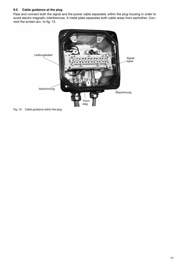
9.5 Cable guidance at the plugPass and connect both the signal and the power cable separately within the plug housing in order toavoid electro magnetic interferences. A metal plate separates both cable areas from eachother. Con-nect the screen acc. to fig. 13.
Fig. 13: Cable guidance within the plug
Leistungskabel
Trenn-steg
Signal-kabel
AbschirmungAbschirmung
11
13.SetupThe actuator only requires the basic settings (adaptation to the operating range) in order to be operatedwith the standard or custumer specific configuration. Use the Local Control Panel (LCP) for these set-tings. Use the appropriate configuration software for more detailed parameter changes or diagnosisfunctions.
13.1Set-up via local control panel (LCP)
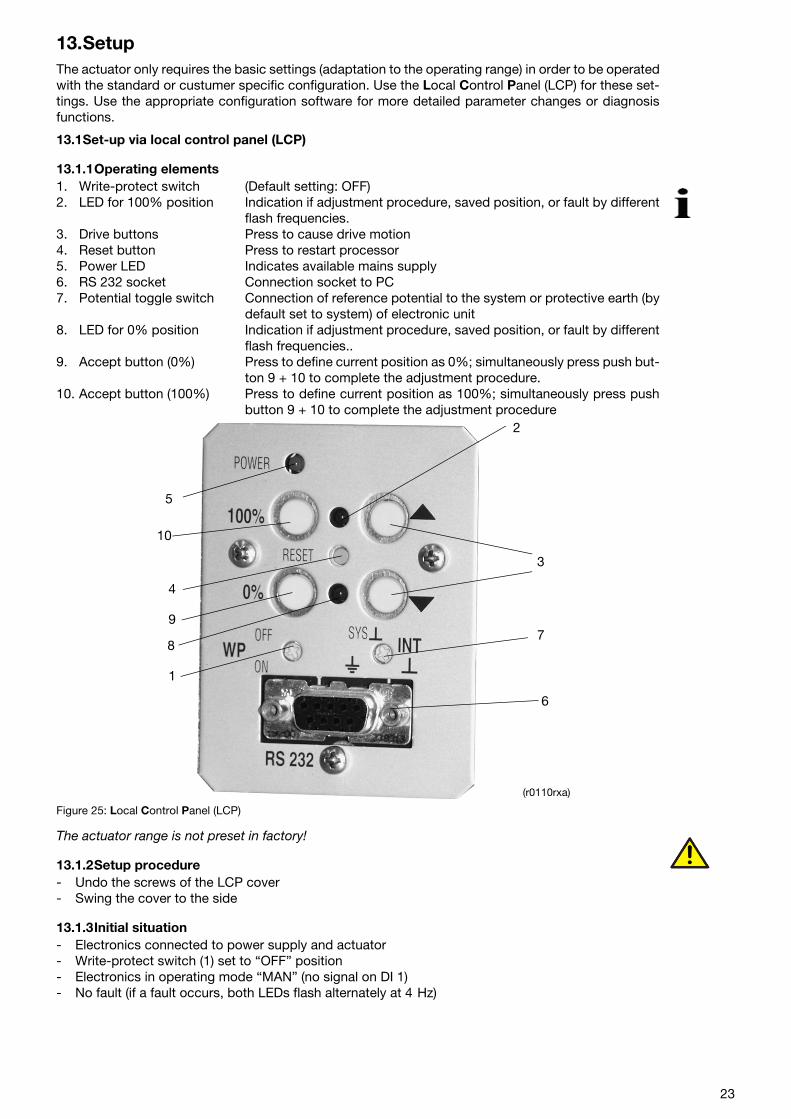
13.1.1Operating elements1. Write-protect switch (Default setting: OFF)2. LED for 100% position Indication if adjustment procedure, saved position, or fault by different
flash frequencies.3. Drive buttons Press to cause drive motion4. Reset button Press to restart processor5. Power LED Indicates available mains supply6. RS 232 socket Connection socket to PC7. Potential toggle switch Connection of reference potential to the system or protective earth (by
default set to system) of electronic unit8. LED for 0% position Indication if adjustment procedure, saved position, or fault by different
flash frequencies..9. Accept button (0%) Press to define current position as 0%; simultaneously press push but-
ton 9 + 10 to complete the adjustment procedure.10. Accept button (100%) Press to define current position as 100%; simultaneously press push
button 9 + 10 to complete the adjustment procedure
Figure 25: Local Control Panel (LCP)
The actuator range is not preset in factory!
13.1.2Setup procedure- Undo the screws of the LCP cover- Swing the cover to the side
13.1.3Initial situation- Electronics connected to power supply and actuator- Write-protect switch (1) set to “OFF” position- Electronics in operating mode “MAN” (no signal on DI 1)- No fault (if a fault occurs, both LEDs flash alternately at 4 Hz)
1
2
3
4
5
6
78
9
10
(r0110rxa)
23
13.1.4Setting
13.1.4.1 “Setting” mode- Set electronics to “setting” mode by pressing both push buttons (3) simultaneously for approx. 5
seconds, until both LEDs (2 + 8) are flashing synchronously at approx. 4Hz. („setting mode“ is thestandard electronic unit status after passing the final factory test)
13.1.4.2 Defining first position (0% or 100%) (Higher precision in 2nd position)
- Move to desired position by pressing one of the push buttons (3).- To accept the position for 0% or 100%, press push button (10) or (9); the associated LED flashes at
approx. 2 Hz when value is correctly accepted, the other one continues to flash at approx. 4Hz
13.1.4.3 Defining second position (0% or 100%)- Move to second position by pressing tho other of the push buttons (3).- To accept the position, press push button (10) or (9); both LEDs (2) and (8) are flashing at approx. 2
Hz when values are accepted correctly.
13.1.4.4 Saving the settings- Save the settings by simultaneously and shortly pressing the push buttons (10 + 9); the LEDs (2 + 8)
are „ON“ (without flashing) for approx. 5 sec before they extinguish and the setting procedure iscompleted.
- If the selected range is too small for the actuator, both LEDs will flash again at 4Hz. Repeat the ad-justment procedure with a wider range (min. positioning travel).(See positioning travel specification on actuator ID label)
13.1.4.5 Correction after setup- If the setting is to be corrected after accepting the first value, first press the Reset button (4) and
then repeat the setting.- If the correction is to be re-done after saving the settings, the entire adjustment procedure must be
repeated.
13.2Adjustment using the configuration programContext-sensitive help information is available in the configuration program at all times. For basic han-dling and installation instructions refer to the associated manual, number 41/68-001.A conductive ground connection is established between the PC and the CONTRAC electronics with theRS 232 communication cable. If the PC is grounded, this may cause a ground loop in the installation.
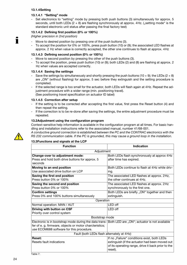
13.3Functions and signals at the LCP
Table 7:
Function Indication
AdjustmentChange-over to adjustment mode:Press and hold both drive buttons for approx. 5 seconds
Both LEDs flash synchronously at approx 4Hz after time has expired.
Moving to an end positionUse associated drive button on LCP
Both LEDs continue to flash at 4Hz while driv-ing.
Saving the first end positionPress button 0% or 100%
The associated LED flashes at approx. 2Hz, the other continues at 4Hz.
Saving the second end positionPress button 0% or 100%
The associated LED flashes at approx. 2Hz synchronously to the first one.
Confirm settingsPress 0% and 100% buttons simultaneously
Both LEDs are briefly „ON“ together and then extinguish.
OperationNormal operation: MAN / AUT LED offDriving with button on CSFPriority over control system
LED off
Bootstrap modeElectronic is in bootstrap mode during the data trans-fer of e. g. firmware, objects or motor charcteristics; use ECOM688 software for this procedure.
Both LED are „ON“; actuator is not available
Fault (both LEDs flash alternately at 4Hz)Reset:Resets fault indications
If no „Failure“ conditions exist, both LEDs extinguish (if the actuator had been moved out of its operating range, drive it back prior to the reset).
24
14. Alarms / Failures14.1 Definition
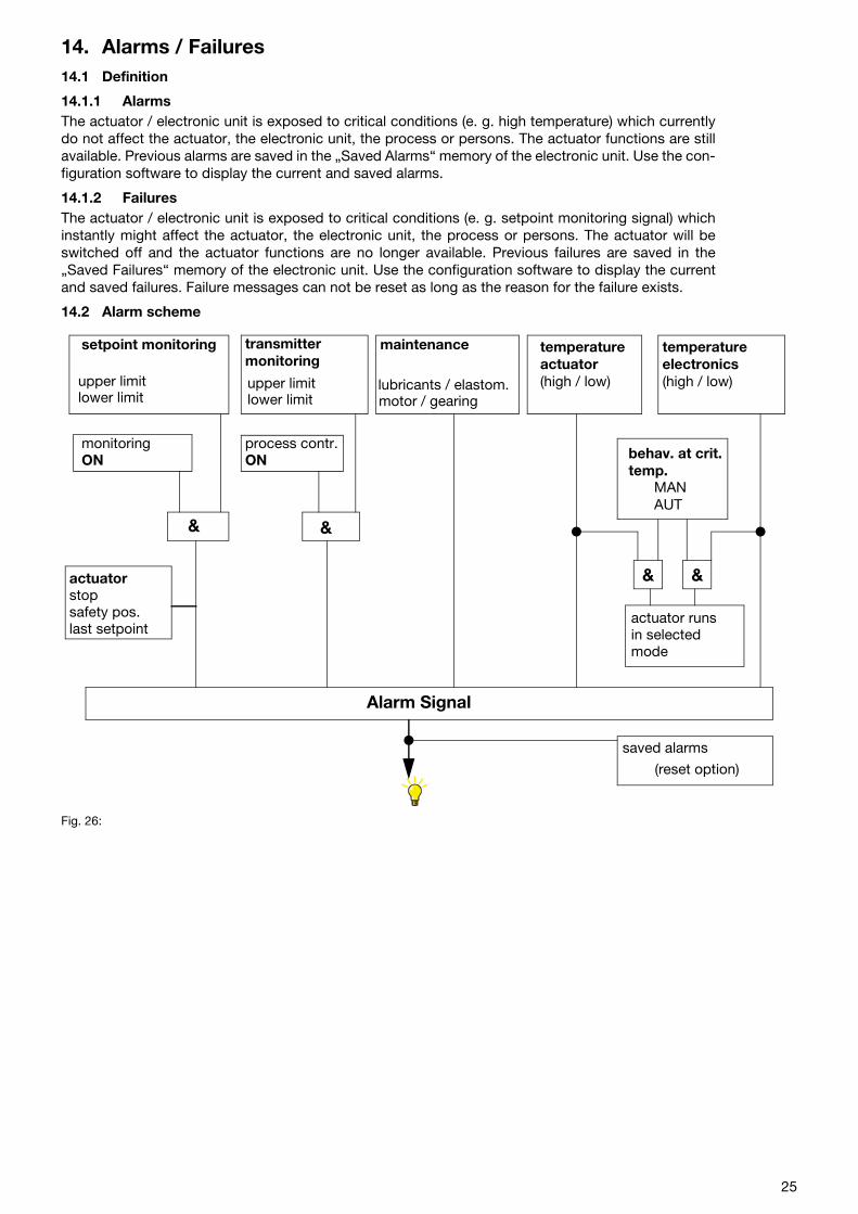
14.1.1 AlarmsThe actuator / electronic unit is exposed to critical conditions (e. g. high temperature) which currentlydo not affect the actuator, the electronic unit, the process or persons. The actuator functions are stillavailable. Previous alarms are saved in the „Saved Alarms“ memory of the electronic unit. Use the con-figuration software to display the current and saved alarms.
14.1.2 FailuresThe actuator / electronic unit is exposed to critical conditions (e. g. setpoint monitoring signal) whichinstantly might affect the actuator, the electronic unit, the process or persons. The actuator will beswitched off and the actuator functions are no longer available. Previous failures are saved in the„Saved Failures“ memory of the electronic unit. Use the configuration software to display the currentand saved failures. Failure messages can not be reset as long as the reason for the failure exists.
14.2 Alarm scheme
Fig. 26:
transmitter temperature
monitoringON
&
Alarm Signal
upper limitlower limit
setpoint monitoringmonitoring
maintenance
lubricants / elastom.motor / gearing
actuator temperatureelectronics
process contr.ON
actuatorstopsafety pos.last setpoint
(high / low) (high / low)
behav. at crit. temp.
MANAUT
actuator runsin selectedmode
saved alarms
(reset option)
&
& &
upper limitlower limit
25
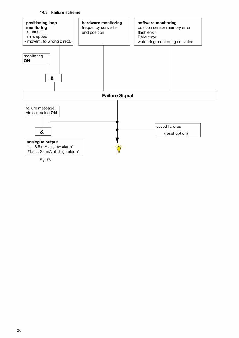
14.3 Failure scheme
Fig. 27:
positioning loop hardware monitoringfrequency converterend position
software monitoringposition sensor memory errorflash errorRAM errorwatchdog monitoring activated
monitoringON
Failure Signal
failure messagevia act. value ON
&saved failures
analogue output1 ... 3.5 mA at „low alarm“21.5 ... 25 mA at „high alarm“
&
monitoring- standstill- min. speed- movem. to wrong direct.
(reset option)
26

15. TroubleshootingThis section mainly describes how to handle hardware errors. Refer to the configuration program’s on-line help for errors related to the software.
Table 8:
Error Possible reason Measures to be taken
Valve cannot be moved by actuator Malfunction of actuator or valve (e.g. stuffing box tightened too much)
Disconnect the actuator from the valve. If the actuator is working properly then, the valve is likely to be defec-tive. Otherwise, the actuator seems to be the error source.
Actuator does not react
Wrong electronic unit or wrong data Compare data lables of actuator and electronic unit
Faulty electronic unit settings Check / modify settings using the configuration software
Faulty communication to DCS Check wiring
Faulty wiring between the electronic unit and the actuator
Check wiring
Motor / brake is defective Check the winding resistances of the motor and brake. Check the brake fuse.
Digital inputs of electronic unit are not connected
Connect
Actuator does not work in automatic mode, although “AUT“ has been selected in the configuration program
Digital input 1 (DI 1) has not been connected.
- Connect DI 1- Check software settings for digital
inputs
LEDs on the commissioning and ser-vice field are flashing simultaneously
Actuator operating range has not been adjusted properly
Adjust the actuator operating range (see instruction for electronic unit).
Fault when approaching an end posi-tion
Actuator is working in the limit range of the position sensor
- Move the actuator either manuallyor with the LCP buttons to a posi-tion beyond the end position (dis-connect from valve if required).
- Move actuator back. If required,reconnect to to the valve (if appli-cable)
- Adapt actuator to new operatingrange
27
ABB has Sales & Customer Supportexpertise in over 100 countries worldwide..
www.abb.com/instrumentation
The Company’s policy is one of continuous productimprovement and the right is reserved to modify the
information contained herein without notice.
Printed in the Fed. Rep. of Germany (08.05)
© ABB 2005
ABB Ltd.Salterbeck Trading EstateWorkington, CumbriaCA14 5DSUKTel: +44 (0)1946 830 611Fax: +44 (0)1946 832 661
ABB Inc.125 E. County Line RoadWarminster, PA 18974USATel: +1 215 674 6000Fax: +1 215 674 7183
ABB Automation Products GmbHSchillerstr. 7232425 MindenGermanyTel: +49 551 905-534Fax: +49 551 [email protected]
42/6
8�82
2 E
N R
ev. D