Embed Size (px)
Citation preview


For the oral rehabilitation
Co
ntents
PROTHODONTIC MANUAL FOR PLATON IMPLANT SYSTEM
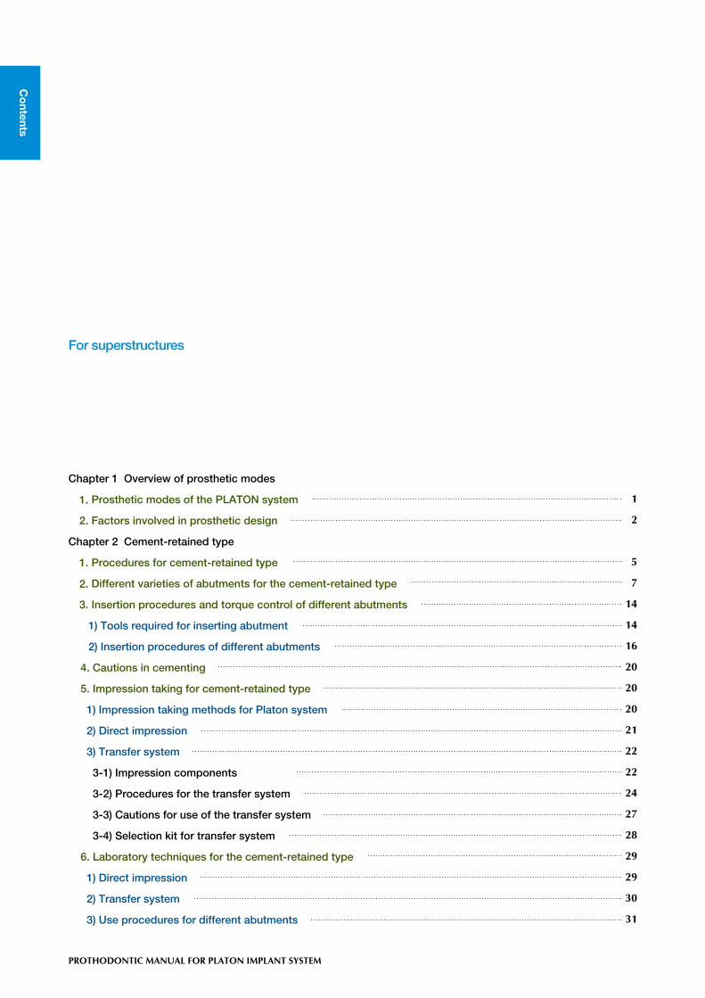
For superstructures
Chapter 1 Overview of prosthetic modes
1. Prosthetic modes of the PLATON system
2. Factors involved in prosthetic design
Chapter 2 Cement-retained type
1. Procedures for cement-retained type
2. Different varieties of abutments for the cement-retained type
3. Insertion procedures and torque control of different abutments
1) Tools required for inserting abutment
2) Insertion procedures of different abutments
4. Cautions in cementing
5. Impression taking for cement-retained type
1) Impression taking methods for Platon system
2) Direct impression
3) Transfer system
3-1) Impression components
3-2) Procedures for the transfer system
3-3) Cautions for use of the transfer system
3-4) Selection kit for transfer system
6. Laboratory techniques for the cement-retained type
1) Direct impression
2) Transfer system
3) Use procedures for different abutments
1
2
5
7
14
14
16
20
20
20
21
22
22
24
27
28
29
29
30
31
On this manual, anchor parts such as " head, cylinder and the rest " described name generically " abutment ".
Introduction
This manual explains handling methods, operation procedures and cau-tions of PLATON IMPLANT SYSTEM. For your full understanding of PLATON SYSTEM, please read this manual carefully before using. This manual should be retained for future reference.
• Before using PLATON SYSTEM, you need fully understanding of surgical operative procedures and operation methods.
• PLATON SYSTEM has been developed for recovering functions and esthetic in the case of edentia.
• After the patient’s general medical and health condition diagnosis, and advisability of treatment, choose a time to start using PLATON SYSTEM.
• Before surgery, enough check the bone quantity, bone quality, mucous thickness, occlu-sal condition and so on.
• Use our PLATON SYSTEM tools in the case of surgery. • PLATON IMPLANT is sterilized medical treatments. Open them immediately before
the operation.• When these implants touch un-clean area, scrap them and use new implants.• Judge the healing time after implantation based on patient’s condition, surgery situation
or objective evaluation standard like Periotest and Osstell. Healing period is about 3 to 6 month only as a guide.
• Before using drills or system tools, make sure to clean and sterilize them.• Do not leave drills and system tools adhesion of blood, bone chips and water. This may
cause discoloration and degradation of them. Make sure to remove blood, bone chips and water completely, after using them. Clean and dry up them, and keep them on the clean area.Drills and system tools keep in the clean area.
For using PLATON SYSTEM

1 PROTHODONTIC MANUAL FOR PLATON IMPLANT SYSTEM
Chap
ter 1O
verview o
f pro
sthetic mo
des
1. Prosthetic modes of the PLATON system
Prosthetic mode of the PLATON system is a cement-retained type.
Chapter 1 Overview of prosthetic modes
《Cement-retained》—Cement-retained abutments• Directly or temporarily cementing this type of the PLATON
system to the abutment heads with cement.• Margin setting can be adaptive to the range of approx.
1.5mm-2mm from supragingival to subgingival in consider-ation of cement removal and a fit-confirming area.
Gingival margin
Subgingival margin
Supragingival margin
Implant marginThe margin location should be decided during implant placement because it is determined by the depth of the placed implant.
margin
① ②
margin
Abutment marginThe margin location should be decided during or after the second surgery or during abutment selection because it is determined on the basis of mucosal thickness (1) and width (2).
2. Factors involved in prosthetic design
1) Classification according to the margin setting of superstructures
• Implant marginThe margin of superstructures is placed on implant bodies.
• Abutment marginThe margin of superstructures is placed at the margin setting part
of abutments.

Overview
of p
rosthetic m
od
es
2 PROTHODONTIC MANUAL FOR PLATON IMPLANT SYSTEM
Chap
ter 1
2) Classification according to the thickness of peri-implant mucosaThe abutments should be selected based on mucosal thickness. The
length of abutment flare and the implant depth accommodate a mucosal thickness of approximately 1.2 to 6.2mm. The corresponding mucosal thick-ness should be approximately 1.5 to 2mm subgingivally for easy cement removal and a fit-confi
In the thinner mucosa, the margin of superstructures should be placed in the mechanically polished part of implants.
3.5mm 4.0mm 5.0mm 6.2mm
mucosal thickness
1.2mm
〜3.2mm
1.5mm
〜2.0mm
〜3.0mm
〜4.2mm
〜
In the thicker mucosa, the abut-ment length should be altered to place the margin of superstruc-tures.
In the thickest mucosa, the margin of super-structures should be placed with the abut-ment length maximized and the mechani-cally polished part not placed in the bone.

3 PROTHODONTIC MANUAL FOR PLATON IMPLANT SYSTEM
Chap
ter 1O
verview o
f pro
sthetic mo
des
3) Classification according to impression methodsThe two impression taking methods are the transfer system and direct
impression.The direct impression method can’t accommodate to the fixed superstructures.
Transfer system
Direct impression technique
Transfer replica
Abutment
Plaster
Insertion of the transfer coping
Impression taking (pick up impression)
A transfer replica is inserted into the transfer coping in the impression, in which plaster compound is poured.
Insertion of the selected abutment into the set plaster model
Preparation of the abutment on the completed working model
Fabrication of superstructure
Insertion of the abutment
Completed working model
Preparation of the abutment into the mouth
Impression taking (direct impression)
Pouring plaster compound into the impression
Fabrication of superstructure

Overview
of p
rosthetic m
od
es
4 PROTHODONTIC MANUAL FOR PLATON IMPLANT SYSTEM
Chap
ter 1
4) Clearance with the opposite tooth and classification of the final superstructures according to the coronal lengthThe depth of the implant and the preparation amount of the abutment
are determined to some extent by the clearance with the opposite tooth or the coronal length of the final superstructure.
5) Classification according to diameters at the superstructure margin (abutment thickness)The types of implants and abutments are determined by the diameter at
the superstructure margin: anterior teeth, premolars or molars.
Premolar Molar

Chap
ter 2C
ement-retained
type
5 PROTHODONTIC MANUAL FOR PLATON IMPLANT SYSTEM
Chapter 2 Cement-retained type1. Procedures for cement-retained type
Points to consider
Head, Extended head or Two-piece head
Insertion of abutment
Preparation into mouth
Direct impression
Temporary restoration
Direct impression (final impression)
Final restoration
Cementation
• Clearance with the opposite tooth
• Mucosal thickness
• Margin location
• Consistency between the implant
axis and the coronal axis
• Coronal width
• Removal of the cap
• Cleaning the inside of implant
• Torque control
• Abutment preparation design
• Rotating speed and rotating direction
of preparing bars
• Retention and antirotation form for
the superstructure
• Margin position
• Accurate reproduction of the margin
and gingival retraction • Active and static functional
restoration
• Preparation of the transmucosal part
• Reconstruction of the interdental
papilla
• Check of cleaning ability
• Providing the peri-margin gingival
margin form
• Verification of pronunciation and
tongue sensation• Accurate reproduction of the margin
and impression taking of the
prepared mucosal form
• Assessment of the temporary
restoration
• Adequate contact with adjacent teeth
• Providing adequate occlusion
• Check adaptation
• Removal of excessive cement
Points to consider
《Direct impression technique》
《Abutment selection》
《Preparation for impression》
《Abutment preparation》
《Impression taking》
《TEK》
《Impression taking》
《Superstructure》
《Insertion》
Flow chart for direct impression technique
1) Direct impression technique

Chap
ter 2
6 PROTHODONTIC MANUAL FOR PLATON IMPLANT SYSTEM
Cem
ent-retained typ
e
Points to consider
Transfer head (Non-engaging),
Transfer head (φ4.2・φ5.5), Angled head, Preparation head,
Gold cylinder, or Temporary cylinder
Insertion of transfer coping
Transfer (open tray)
Recheck/preparation of abutment on the model
Temporary restoration
Transfer (open tray)
Final restoration
Insertion of abutment
Points to consider
• Fabrication of the open tray
• Removal of the cap
• Cleaning the inside of implant
• Check the interlocking end
subgingivally
• Connect the copings in the multiple
tooth case
• Impression of the prepared mucosal form
• Fabrication of the index
• Cleaning the inside of implant
• Torque control
Cementation
《Transfer system》
• Clearance with the opposite tooth
• Mucosal thickness
• Margin location
• Consistency between the implant
axis and the coronal axis
• Coronal width
• Abutment preparation design
• Retention and antirotation form for
the superstructure
• Margin position
• Assessment of the temporary
restoration
• Adequate contact with adjacent teeth
• Providing adequate occlusion
• Check adaptation
• Removal of excessive cement
• Active and static functional
restoration
• Preparation of the transmucosal part
• Reconstruction of the interdental
papilla
• Check of cleaning ability
• Providing the peri-margin gingival
margin form
• Verification of pronunciation and
tongue sensation
《Abutment selection》
《Preparation for impression》
《Impression taking》
《Preparation》
《TEK》
《Final impression taking》
《Superstructure》
《Preparation for insertion》
《Insertion》
Flow chart for transfer system
2) Transfer system

Chap
ter 2C
ement-retained
type
7 PROTHODONTIC MANUAL FOR PLATON IMPLANT SYSTEM
2. Different varieties of abutments for the cement-retained type
The abutments are classified according to the margin set position (the margin set at the platform on the implant side or the margin set on the abutment side) or whether the implant is to be adaptive to the transfer system (Table 1).
Head
Margin set Whether or not to be adaptive to the transfer system
Implant side ×
Cementing abutments
Angled head (Non-engaging) Implant side
○Implant side
○
Transfer head (Non-engaging)
Preparation head
Transfer head φ4.2
Abutment side ×
Abutment side ○
Abutment side ○
Two-piece head
Angled head (Engaging)
Preparation head
Gold cylinder
Abutment side ○
Abutment side
○
Abutment side
○Abutment side
○
Transfer head φ5.5
Abutment side
○
Temporary cylinder
Abutment side ×Extended Head
AbutmentMargin
Mechanically-polished part (transmucosal part)
Intraosseous-placed part Implant
Table 1

Chap
ter 2
8 PROTHODONTIC MANUAL FOR PLATON IMPLANT SYSTEM
Cem
ent-retained typ
e
Transfer system : InadaptableMargin : Implant marginMaterial : Titanium
Head Used as abutments for single standing. The structure of the screw
- built-in, one-piece - allows the same prosthetic operation as natural teeth through the following procedures: preparation into the mouth, direct impression, working plaster model, and fabrication of the super-structure.
Extended HeadThese abutments are an integration of the abutment part and
the transmucosal part. The structure of the screw - built-in one-piece - allows the same prosthetic operation as natural teeth through the following procedures: preparation into the mouth, direct impression, working plaster model, and fabrication of the superstructure. The trans-mucosal part can be customized and the margin can be set freely.
Tools for insertion :Taper angle of the abutment part :
Head holder (S, M, and L)6°
Abutment length (height)
S4.0mm
L7.0mm
M5.5mm
Height
Tools for insertion :Taper angle of the abutment part :
Diameter :
Hex driver6°4.0 mm
Transfer system : InadaptableMargin : Abutment marginHealing abutment : φ 4.0Material : Titanium
Abutment length (height)/Transmucosal part (G)
Height
G
SHeight : 7.0mm
G : 1.8mm
LHeight : 8.2mm
G : 2.6mm
Chap
ter 2C
ement-retained
type
9 PROTHODONTIC MANUAL FOR PLATON IMPLANT SYSTEM
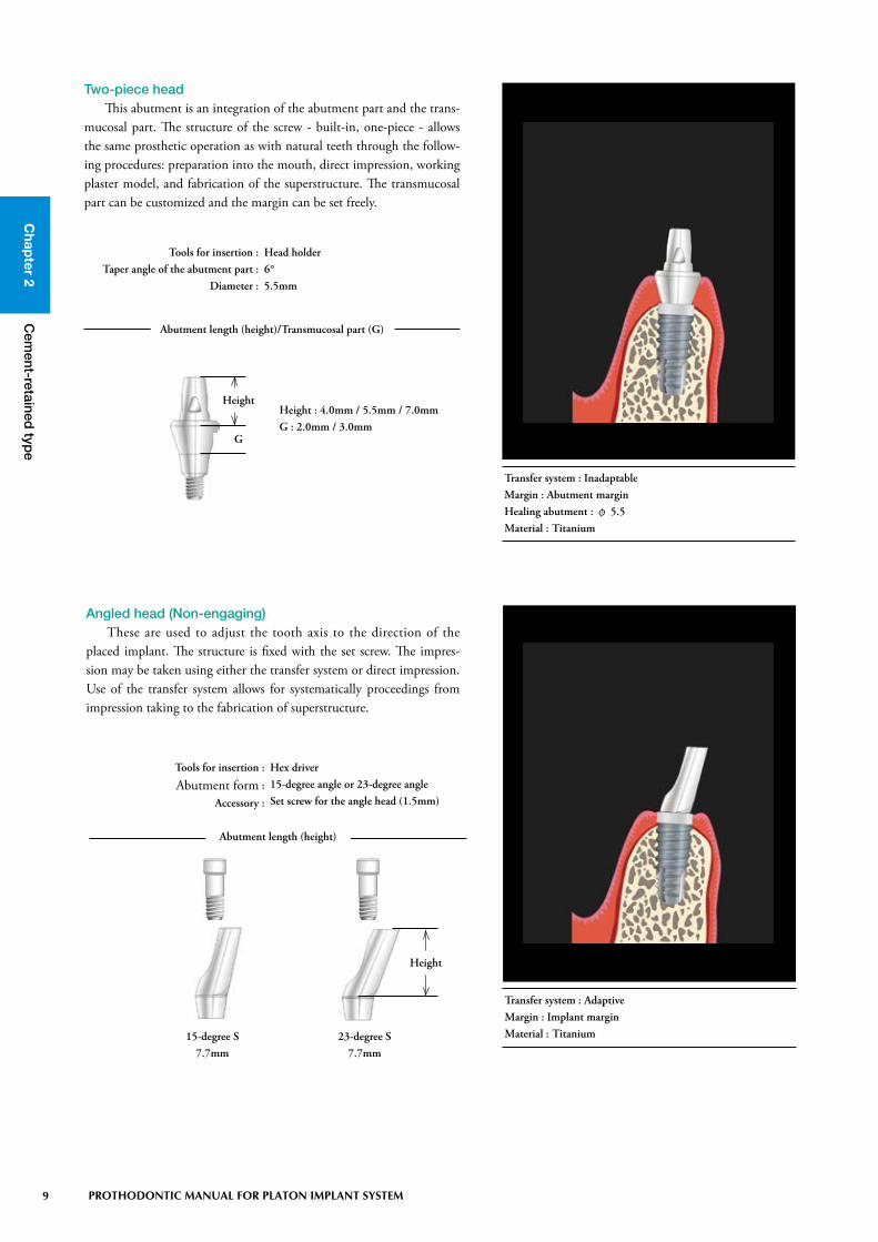
Two-piece headThis abutment is an integration of the abutment part and the trans-
mucosal part. The structure of the screw - built-in, one-piece - allows the same prosthetic operation as with natural teeth through the follow-ing procedures: preparation into the mouth, direct impression, working plaster model, and fabrication of the superstructure. The transmucosal part can be customized and the margin can be set freely.
Abutment length (height)/Transmucosal part (G)
Tools for insertion :Taper angle of the abutment part :
Diameter :
Head holder6°5.5mm
Height
G
Height : 4.0mm / 5.5mm / 7.0mmG : 2.0mm / 3.0mm
Transfer system : InadaptableMargin : Abutment marginHealing abutment : φ 5.5Material : Titanium
Angled head (Non-engaging)These are used to adjust the tooth axis to the direction of the
placed implant. The structure is fixed with the set screw. The impres-sion may be taken using either the transfer system or direct impression. Use of the transfer system allows for systematically proceedings from impression taking to the fabrication of superstructure.
Tools for insertion :
Abutment form :
Accessory :
Hex driver15-degree angle or 23-degree angleSet screw for the angle head (1.5mm)
Abutment length (height)
23-degree S7.7mm
15-degree S7.7mm
Height
Transfer system : AdaptiveMargin : Implant marginMaterial : Titanium

Chap
ter 2
10 PROTHODONTIC MANUAL FOR PLATON IMPLANT SYSTEM
Cem
ent-retained typ
e
Angled head (Engaging) The operative procedure used is the same as with angled heads
(non-engaging), and the internal hex (hexagonal structure) is designed as a lock mechanism at the interface with implants. The customizable transmucosal part and free margin setting facilitate reproduction of the anatomy.
Tools for insertion :Taper angle of the abutment part :
Accessory :
Hex driver6°Set screw H2 (2mm)
Abutment length (height)
M5.5mm
S4.0mm
L7.0mm
Height
Transfer system : AdaptiveMargin : Implant marginMaterial : Titanium
Tools for insertion :Abutment form :
Diameter :Accessory :
Hex driver15-degree angle or 23-degree angle5.0mmSet screw H2 (2mm)
Transfer system : Adaptive Margin : Abutment marginHealing abutment : φ 5.5Material : Titanium
Abutment length (height)/Transmucosal part (G)
Height
G
15-degreeHeight : 7.0mm
G : 2.0mm / 4.0mm
23-degreeHeight : 7.0mm
G : 2.0mm / 4.0mm
Transfer head (Non-engaging)These are normal-type abutments adaptive to the transfer system.
The structure is fixed with the set screw and the transfer system can be used to systematically proceed from impression taking to the fabrica-tion of superstructure.

Chap
ter 2C
ement-retained
type
11 PROTHODONTIC MANUAL FOR PLATON IMPLANT SYSTEM
Transfer head φ φ4.2 The intended purpose is the same as transfer heads (non-engaging),
and the internal hex (hexagonal structure) is designed as a lock mecha-nism at the interface with implants. This is a single-unit construction of the abutment part and the transmucosal part, and is fixed with a set screw. The transmucosal part can be customized and the margin can be freely set.
Transfer head φ φ5.5 The intended purpose is the same as transfer heads (non-engaging),
and the internal hex (hexagonal structure) is designed as a lock mecha-nism at the interface with implants. This is a single-unit construction of the abutment part and the transmucosal part, and is fixed with a set screw. The transmucosal part can be customized and the margin can be freely set.
Tools for insertion :Taper angle of the abutment part :
Diameter :Accessory :
Hex driver6°4.2mmSet screw H2 (2mm) and H4 (4mm)
Abutment length (height)/Transmucosal part (G)
Height
G
Height : 4.0mm / 5.5mm / 7.0mmG : 1.5mm / 2.0mm / 3.0mm
Transfer system : AdaptiveMargin : Abutment marginHealing abutment : φ 4.0Material : Titanium
Tools for insertion :Taper angle of the abutment part :
Diameter :Accessory :
Hex driver6°5.5mmSet screw H2 (2mm) and H4 (4mm)
Abutment length (height)/Transmucosal part (G)
Height
G
Height : 4.0mm / 5.5mm / 7.0mmG : 1.5mm / 2.0mm / 3.0mm
Transfer system : Adaptive Margin : Abutment marginHealing abutment : φ 5.5Material : Titanium

Chap
ter 2
12 PROTHODONTIC MANUAL FOR PLATON IMPLANT SYSTEM
Cem
ent-retained typ
e
Tools for insertion :Abutment form :
Diameter :Accessory :
Hex driverStraight5.0mmSet screw H2 (2mm)
Abutment length (height)/Transmucosal part (G)
Height
G
Height : 7.0mmG : 1.5mm
Transfer system : Adaptive Margin : Abutment marginHealing abutment : CustomMaterial : Titanium
Tools for insertion :Cylinder form :
Diameter :Accessory :
Hex driverStraight (knurling processing: mechanical retention)3.0mmSet screw H2 (2mm)
Abutment length (height)
Height Height : 9.0mm
Transfer system : Adaptive Margin : Abutment marginHealing abutment : FreeMaterial : Titanium
Preparation headThis is the abutment used for grinding preparation adaptive to
the transfer system. The structure is fixed with the set screw and can be prepared from an arbitrary form on the laboratory side. Use of the transfer system allows for systematically proceedings from impression taking to the fabrication of superstructure. The large-diameter abut-ment, customizable transmucosal part, and free margin setting facili-tate reproduction of the anatomy.
The internal hex (hexagonal structure) is designed at the interface with implants as a lock mechanism.
Temporary cylinderThis is an abutment used as the interior of temporary restorations.
The cylinder surface allows retention to resin. The internal hex (hex-agonal structure) is designed as a lock mechanism at the interface with implants. As with other applications, this is more effective for fabricat-ing custom healing abutments.

Chap
ter 2C
ement-retained
type
13 PROTHODONTIC MANUAL FOR PLATON IMPLANT SYSTEM
Tools for insertion :Cylinder form :
Diameter :Accessory :
Hex driverStraight4.0mmSet screw H2 (2mm)
Height Height : 10mm
Abutment length (height)
Transfer system : Adaptive Margin : Abutment marginHealing abutment : CustomMaterial : Non-oxidation alloy Polyoxymethylene resin (cylinder part)
Gold cylinder This is a cast-type gold abutment, which is waxed up to fabricate
an abutment through cast joint. The internal hex (hexagonal structure) is designed as a lock mechanism at the interface with implants. The transmucosal part and abutment for can be customized and the margin can be freely set. Therefore, this can be used for single defects and par-tial defects from edentulism.

Chap
ter 2
14 PROTHODONTIC MANUAL FOR PLATON IMPLANT SYSTEM
Cem
ent-retained typ
e
3. Insertion procedures and torque control of different abutments
1) Tools required for inserting abutmentThe following tools are used for inserting abutments. Take note
that tools differ according to the abutment of choice.
Head holderThis is used for insert ion of different heads (S. M. L), extended
heads, and a two-piece head. Each head is inserted into the implant with the round driver, ratchet, and torque ratchet while bracing the abutment part of each head with the head holder.
Hex driverThese are used for insertion of set-screw fixed abutments. The driv-
er is inserted into the hex (hexagonal structure) provided at the top of abutment or set screw to carry into the mouth. Each abutment is then inserted into the implant with the round driver, ratchet, and torque ratchet.
Length : 14mm
Material : Stainless steel
Material : Titanium alloy
SS (length : 14mm)S (length : 21mm)L (length : 30mm) SS LS

Chap
ter 2C
ement-retained
type
15 PROTHODONTIC MANUAL FOR PLATON IMPLANT SYSTEM
Torque ratchetThis is used to control a torque during insertion of each abutment
and has an easy-to-use ratchet mechanism.
Ncm
203040
Length : 111mm
Material : Stainless steel
Material : Stainless steel
S (length : 15mm)L (length : 22mm)
LS
ExtensionWhen tools cannot be inserted due to the narrow space between
the implant and the adjacent tooth, these are used to extend the verti-cal dimension of the implant holders or head holders.
Material : Stainless steel
Diameter : 17mm Diameter : 10mm
Round driverThese are hand drivers used for insertion of each holder. They are
used when manual tightening of screws or components is necessary. When the tightening torque is determined, they are used as drivers for pre-tightening before using a torque ratchet. Two types of sizes, by diameter, are provided corresponding to the insufficient space between the implant and adjacent tooth.

Chap
ter 2
16 PROTHODONTIC MANUAL FOR PLATON IMPLANT SYSTEM
Cem
ent-retained typ
e
2) Insertion procedures of different abutmentsHead / Extended head / Two-piece head
After verification of osseointegration, the cap is removed with a hex driver. The interior of the cap removed implant is cleaned and dried to prevent any foreign matter from getting inside prior to insertion of each abut-ment.
The abutment is inserted into a head holder to carry it into the mouth. The use of rubber dam is recommended to avoid misde-glutition.
The round driver or torque ratchet is fitted on the head holder, and is rotated until the turning of the abutment stops.
Torque control is performed with a torque ratchet. The recommended tightening torque is in the range of 25 to 30N.

Chap
ter 2C
ement-retained
type
17 PROTHODONTIC MANUAL FOR PLATON IMPLANT SYSTEM
• Where the superstructure was fabricated through the transfer system, the abutment is replaced to the in-traoral accurate positional relationship from the model with the transfer index.
After verification of osseointegration, the cap is removed with a hex driver. The interior of the cap removed implant is cleaned and dried to prevent any foreign matter from getting inside prior to insertion of each abut-ment.
The abutment is inserted into the implant, taking care with the axial surface and angle.
After verification of the direction of the abutment, the round driver or torque ratchet is mounted on a hex driver while bracing the abutment with a plier. It is then rotated until the turning of the set screw stops.
Angled head
• The recommendation is to fill the screw hole with pledget and resin.
Torque control is performed with a torque ratchet. The recommended tightening torque is in the range of 25 to 30N.

Chap
ter 2
18 PROTHODONTIC MANUAL FOR PLATON IMPLANT SYSTEM
Cem
ent-retained typ
e
• The recommendation is to fill the screw hole with pledget and resin.
Torque control is performed with a torque ratchet. The recommended tightening torque is in the range of 25 to 30N.
Transfer head (Non-Engaging) / Transfer head φ 4.2 ・φ 5.5Preparation head
After verification of osseointegration, the cap is removed with a hex driver. The interior of the cap removed implant is cleaned and dried to prevent any foreign matter from getting inside prior to insertion of each abut-ment.
After verification of the direction of the abutment, the round driver or torque ratchet is mounted on a hex driver while bracing the abutment with a plier. It is then rotated until the turning of the set screw stops.
The abutment is inserted into the implant, taking care with the axial surface and angle.
• Where the superstructure was fabricated through the transfer system, the abutment must be replaced to the intraoral accurate positional relationship from the model with the transfer index.

Chap
ter 2C
ement-retained
type
19 PROTHODONTIC MANUAL FOR PLATON IMPLANT SYSTEM
• The recommendation is to fill the screw hole with pledget and resin.
Torque control is performed with a torque ratchet. The recommended tightening torque is in the range of 25 to 30N.
Temporary cylinder / Gold cylinder
After verification of osseointegration, the cap is removed with a hex driver. The interior of the cap removed implant is cleaned and dried to prevent any foreign matter from getting inside prior to insertion of each abut-ment.
After verification of the direction of the abutment, the round driver or torque ratchet is mounted on a hex driver while bracing the abutment with a plier. It is then rotated until the turning of the set screw stops.
The abutment is inserted into the implant, taking care with the axial surface and angle.
• Where the superstructure was fabricated through the transfer system, the abutment must be replaced to the intraoral accurate positional relationship from the model with the transfer index.

Chap
ter 2
20 PROTHODONTIC MANUAL FOR PLATON IMPLANT SYSTEM
Cem
ent-retained typ
e
4. Cautions in cementing
5. Impression taking for cement-retained type
Cementing superstructures may use the same cements as in pros-thetic restoration of natural teeth. However, since changes in the peri-implant environment are most significant during a certain period of time from insertion of superstructures, the simplicity of maintenance including a minor adjustment of the occlusal change and form, and observation of the surrounding tissue is required. Therefore, temporary cement should be used during cementation. Be careful about the items described on the right.
• Thoroughly remove excessive cement.• If necessary, a spill hole may be provided for prosthesis (resin
cement).• Check adaptation and retention of prosthesis at an adequate
recall.
Impression taking methods for the Platon implant system include two techniques of direct impression and the transfer system. The direct impression is a method that impression of the intraoral abutment is taken directly into the mouth as natural teeth. The superstructure is fabricated on the working plaster model without special components as a conventional prosthesis. The transfer system is a method that the impression is taken through pick-up impression copings to reproduce the positional relationship at the intraoral implant or abutment level on the model and fabricate the superstructure. Take note that impres-sion copings differ according to the abutment of choice.
1) Impression taking methods for Platon system
Direct impression
Impression method
Transfer system
Impression coping abutment
Head
Extended head
Two-piece head
Transfer coping
Angled head (Non-Engaging)
Angled head (Engaging)
Transfer head (Non-Engaging)
Transfer head φ4.2・φ5.5
Preparation head
Temporary cylinder
Gold cylinder
When setting the emerging profile of the superstructure directly from the implant body (implant margin), select a replica with the same diameter as the implant without any modification. The choice of abutment at the time should be limited to abut-ment types that can set the margin on the implant body.

Chap
ter 2C
ement-retained
type
21 PROTHODONTIC MANUAL FOR PLATON IMPLANT SYSTEM
2) Direct impressionThe direct impression is a technique that the impression of the pre-
pared abutment is taken with a ready made tray to fabricate the super-structure on the working plaster model.
Preparation is performed, if necessary, after insertion of the abutment. Prepare the abutment under a large volume of irrigation in consideration of antirotation of the super-structure in simple restorations and parallel-ism in multiunit bridges.
Silicone impression materials are used. The periphery of the abutment should be covered with a flowable silicone impression material to accurately reproduce around the margin. This allows for reproducing the clear margin line.
Plaster is poured, paying attention not to entrap air around the abutment. Remove the plaster model from the impression, being careful not to damage the abutment part. The completed plaster model is transported to the laboratory.

Chap
ter 2
22 PROTHODONTIC MANUAL FOR PLATON IMPLANT SYSTEM
Cem
ent-retained typ
e
If there should be any problem, including the range of mouth opening, make the shift to either set screw H10 or H7.Set screw H10 : (S) Protruding length 4.0mm (L) Protruding length 1.0mmSet screw H7 : (S) Protruding length 1.0mm
3) Transfer systemThe transfer system can be used to systematically proceed from
impression taking to the fabrication of superstructure. Use of the sys-tem allows transport of the implant to the model, the detail consider-ation of the abutment length based on the clearance with the opposite tooth, and preparation of the abutment on the model. The impression methods include the close tray technique using a ready-made tray and the open tray technique using an individual tray.
3-1) impression componentsTransfer coping
These are screw-retained impression parts that are secured to the implant with each set screw, and, the internal hex (hexagonal structure) is provided. Because an individual tray (open tray) is used while taking impression, it is necessary to prepare it before taking the impression. The use of titanium alloy allows repeated use.
S L
HeightG
Height : 6.0mmG : 3.0mm
HeightG
Height/Transmucosal part (G)
Height : 9.0mmG : 6.0mm
Tools for insertion :Accessory :
Hex driver(S) Set screw H12 (12mm)(L) Set screw H15 (15mm)
Impression tray : Individual tray (open tray)Material : Titanium alloy

Chap
ter 2C
ement-retained
type
23 PROTHODONTIC MANUAL FOR PLATON IMPLANT SYSTEM
Transfer replicaThese are model dummy implants. They are for cases where abut-
ments are used, or the margin is set on implants. The use of titanium alloy allows repeated use.
Size (diameter)
Material : Stainless steel
PFφ 4.1Diameter : 4.1mm
PFφ 5.0Diameter : 5.0mm
Set screwThese are used to fix transfer coping or each replica.
If difficulty is experienced inserting the transfer coping, due to a smaller range of the mouth opening, make an exchange to a shorter set screw. The recommendation is to prepare different sizes of set screws.
Tools for insertion : Hex driver
Length (height)
Height
Protruding length
Material : Titanium alloy
H0.50.5mm
H22.0mm
H44.0mm
H77.0mm
H1010mm
H1515mm

Chap
ter 2
24 PROTHODONTIC MANUAL FOR PLATON IMPLANT SYSTEM
Cem
ent-retained typ
e
3-2) Procedures for the transfer system
Consideration of abutment length and
transmucosal length (G) (on model)
CHAIR SIDE
Fabrication of individual tray (open tray)
※ A through-hole for a set screw at the site
to be transferred should be prepared.
LABORATORY SIDE
Snap impression
First surgery / Second surgery
Placement of transfer coping
Silicone impression Placement of transfer coping
Fabrication of working model
Preparation of abutment (on model)
Fabrication of provisional restoration
Fabrication of final restoration
Insertion of abutment
(model → into the mouth)
Set of superstructure
Insertion of cap or healing abutment
Placement of temporary crown

Chap
ter 2C
ement-retained
type
25 PROTHODONTIC MANUAL FOR PLATON IMPLANT SYSTEM
• A snap impression is needed so that the implant position and direction can be determined. This allows fabrication of an accurate open tray and impression taking with stable accuracy.
Impression procedures for transfer coping (individual tray)
After verification of osseointegration, a snap impression is taken to fabricate an in-dividual tray prior to impression taking. On the individual tray, a through-hole for the set screw should be prepared with the transfer coping.
After removal of the cap, the transfer cop-ing is placed on the implant with the provid-ed set screw using a hex driver. The set screw should be driven until it stops without being tightened too much.
• In the case of patient’s limited jaw range, the set screw is replaced with a shorter one or a hex driver SS is used.
• When multiple teeth are transferred, the transfer copings should be connected to each other with pattern resin.
• The implants utilize the internal hex. The transfer coping should be fitted on the implant to match the internal hex. In invisibly subgingival cases, verify the fit between the transfer coping and the implant on the X-ray.
• In cases of more than 6 mm subgingivally, two fins of the transfer coping should be ground and adjusted; however, extreme grinding may cause the impression to move.
Chap
ter 2
26 PROTHODONTIC MANUAL FOR PLATON IMPLANT SYSTEM
Cem
ent-retained typ
e
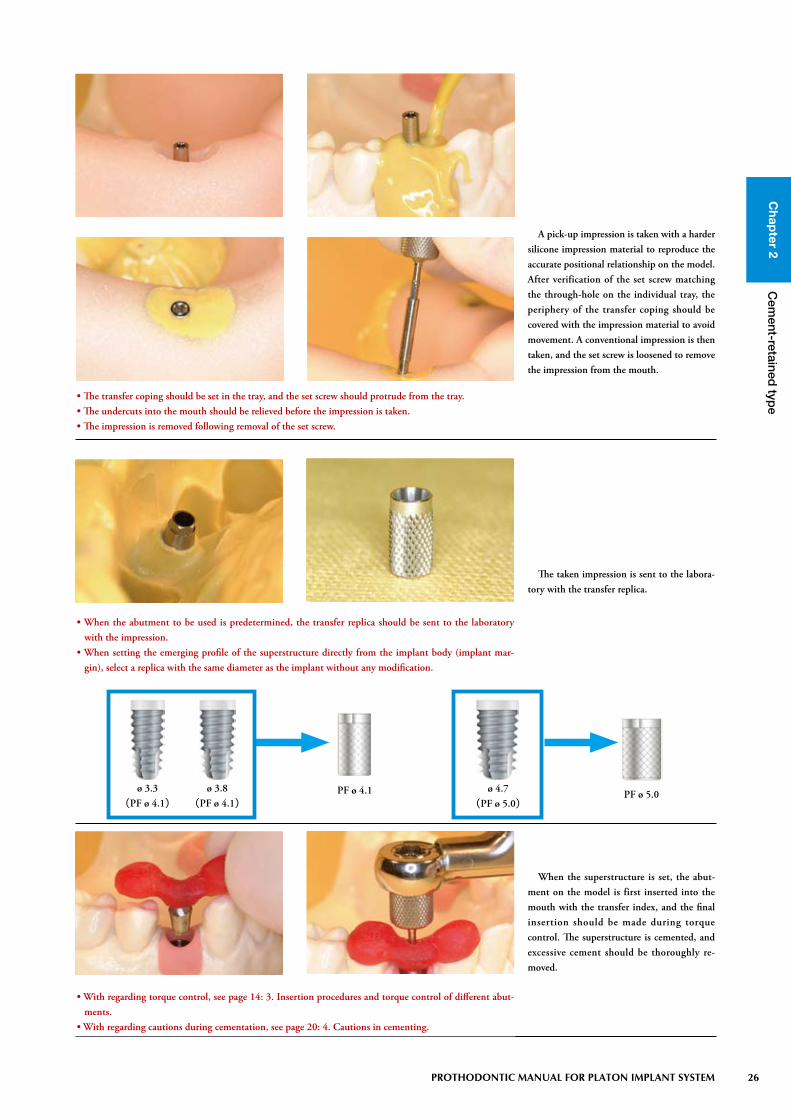
A pick-up impression is taken with a harder silicone impression material to reproduce the accurate positional relationship on the model. After verification of the set screw matching the through-hole on the individual tray, the periphery of the transfer coping should be covered with the impression material to avoid movement. A conventional impression is then taken, and the set screw is loosened to remove the impression from the mouth.
• The transfer coping should be set in the tray, and the set screw should protrude from the tray. • The undercuts into the mouth should be relieved before the impression is taken.• The impression is removed following removal of the set screw.
The taken impression is sent to the labora-tory with the transfer replica.
When the superstructure is set, the abut-ment on the model is first inserted into the mouth with the transfer index, and the final insertion should be made during torque control. The superstructure is cemented, and excessive cement should be thoroughly re-moved.
• When the abutment to be used is predetermined, the transfer replica should be sent to the laboratory with the impression.
• When setting the emerging profile of the superstructure directly from the implant body (implant mar-gin), select a replica with the same diameter as the implant without any modification.
PF ø 4.1 PF ø 5.0ø 3.3
(PF ø 4.1)ø 3.8
(PF ø 4.1)ø 4.7
(PF ø 5.0)
• With regarding torque control, see page 14: 3. Insertion procedures and torque control of different abut-ments.
• With regarding cautions during cementation, see page 20: 4. Cautions in cementing.

Chap
ter 2C
ement-retained
type
27 PROTHODONTIC MANUAL FOR PLATON IMPLANT SYSTEM
3-3) Cautions for use of the transfer systemPreoperative examination, diagnosis, and adaptation• The transfer system can not always be used by the circumstances including
clearance with the opposite tooth, the range of mouth opening, and the occlusal condition of remaining teeth. Adequate examination and diagno-sis can determine the transfer system placement position and direction.
Healing Period• The healing period varies depending on the bone quality, age of patient,
and site of placement. Before using the transfer system, examine implant mobility, check the presence or absence of transmission image on X-ray, and check the peri-implant’s mucosal condition.
Oral care• Occlusal contact and adaptive condition of superstructures may cause
bone resorption, screw loosening and fracture. Perform regular mainte-nance to check for loosening of screws and occlusal condition.
Transfer system• The system is adaptable to the transfer head, preparation head, angled
head, gold cylinder, and temporary cylinder.• Use requires verifying the size of the implant to be placed into the mouth.
The platform (PF) diameter varies according to implant size, so use the system that matches the PF diameter.
• The system cannot be used when preparing the mechanically-polished part of the implant.
• When preparing the mechanically-polished part of implant, the system cannot be used.
• When setting the emerging profile of superstructure directly from the implant body (implant margin), select a replica with the same diameter as the implant without any modification.

Chap
ter 2
28 PROTHODONTIC MANUAL FOR PLATON IMPLANT SYSTEM
Cem
ent-retained typ
e
3-4) Selection kit for transfer systemSelection of abutments should be made, if possible, through insert-
ing the real thing into the mouth or on the model. Since the selection kit includes abutments usable in the transfer system, the optimal part can be selected through trials on the model.
Consideration/verification of the optimal abut-ment length and mucosal level
Consideration/verification of angulation of abutment
(1) Transfer heads (S, M, and L)(2) Preparation heads (one-stage technique and two-
stage technique)(3) Angled heads (15°S, 23°S, 15°L)(4) Set screws (H0.5 and H2)
(1) (2)
(3) (4)

Chap
ter 2C
ement-retained
type
29 PROTHODONTIC MANUAL FOR PLATON IMPLANT SYSTEM
Laboratory techniques for the PLATON implant system include the following two methods:
The first method fabricates the superstructure on the removable plaster die (abutment) with the margin, just like the fabrication of prostheses for natural teeth.
The second method uses the transfer system, allowing systematic performance of impression taking, fabrication of the working model, choice/ preparation of the abutment to be used, and fabrication of the superstructure. The later transfer system can use the optimal abutment for the superstructure to be fabricated, because transfer of the implant on the working model allows detailed consideration of the abutment type and its length according to clearance with the opposite tooth and preparation of the abutment on the model. Also, the system gives full play to the dental technician’s abilities.
6. Laboratory techniques for the cement-retained type
1) Direct impression
With regarding the detail impression taking technique, see page 21: 2) Direct im-pression.
The working model is fabricated in the usual manner, carefully trimming the margins with a knife or a round bar.
• The working model should be fabricated as a soft gum cast to allow verification of the peri-implant mu-cosal form.

Chap
ter 2
30 PROTHODONTIC MANUAL FOR PLATON IMPLANT SYSTEM
Cem
ent-retained typ
e
Technical procedures for transfer coping
The transfer replica is inserted into the trans-fer coping in the impression, fixing it with the set screw using a hex driver.
The working model should be fabricated, paying attention not to entrap air.
With regarding the detail impression taking technique, see page 25 to 26: Impres-sion taking procedures for transfer coping Pro.
• When multiple teeth are transferred, the transfer replicas should be connected to each other with pattern resin.
• When the transfer replica is inserted into the transfer coping, the set screw should be tighten while hold-ing the replica.
2) Transfer system

Chap
ter 2C
ement-retained
type
31 PROTHODONTIC MANUAL FOR PLATON IMPLANT SYSTEM
3) Use procedures for different abutments
The abutments of the PLATON system include the following two types:
The first type uses the same technique as prosthesis for natural teeth through intraoral abutment preparation, direct impression, and fabrication of superstructure on the plaster model (one-piece type of abutment and screw combined).
The other type allows systematic use through fabrication of the plaster model with insertion of the metal implant replica in according with the transfer system and abutment choice/preparation, and fabri-cation of the superstructure on the laboratory side (two piece type of abutment and set screw).
The two-piece types of abutments responding to the transfer sys-tem are described here.
Angled head
The selected different angle head is fixed on the transfer replica into the model with the supplied set screw.
• For the subgingival margin or the margin along the periphery, the gum model should be fabricated to check peri-implant mucosal form.
• Be aware that the different angle heads may not correspond to the type of replicas. • When setting the emerging profile of the superstructure directly from the implant body (implant mar-
gin), select a replica with the same diameter as the implant without any modification.
Transfer replicaImplant side Angled head (Non-Engaging)
Angled head (Engaging)Abutment side
Margin setting Criterion for selecting abutmentModel replica

Chap
ter 2
32 PROTHODONTIC MANUAL FOR PLATON IMPLANT SYSTEM
Cem
ent-retained typ
e
The different angled heads should be pre-pared, taking parallelism, the path of inser-tion of the superstructure, the mucosal form, the final prosthetic form, and interproximal undercuts into consideration. If necessary, a measuring rod from a milling machine or a dental surveyor should be used.
• Replacement with the alternative transfer replica facilitates preparation of different angle heads. Because an intense heat may be generated during preparation, preparing should be made while cooling.
• Because the different angle heads are made with titanium, porcelain cannot be fused directly on their sur-face.
The transfer index should be fabricated with pattern resin to ensure replacement of differ-ent angle heads into the mouth.
• The transfer index should be fabricated in order to avoid deformation by torque and to keep the transfer head from moving.
Torque control is performed with a torque ratchet. The recommended tightening torque is in the range of 25 to 30N.
• After insertion of different angle heads, the recommendation is to fill the screw hole with pledget and resin.
• Sandblasting the surface of different angle heads is recommended to increase retention of cement.

Chap
ter 2C
ement-retained
type
33 PROTHODONTIC MANUAL FOR PLATON IMPLANT SYSTEM
Transfer head (Non-Engaging)/ Transfer head φ 4.2・φ 5.5
The selected transfer head is fixed on the transfer replica into the model with the sup-plied set screw.
• For the subgingival margin or the margin along the periphery, the gum model should be fabricated to check peri-implant mucosal form.
• When setting the emerging profile of the superstructure directly from the implant body (implant mar-gin), select a replica with the same diameter as the implant without any modification.
Transfer replica
Margin setting Criterion for selecting abutment
Implant side Transfer head (Non-engaging)
Abutment side Transfer head φ4.2・φ5.5
Model replica
The transfer head should be prepared, tak-ing parallelism, the path of insertion of the superstructure, the mucosal form, the final prosthetic form, and interproximal undercuts into consideration. If necessary, a measuring rod from a milling machine or a dental sur-veyor should be used.
• Replacement with the alternative transfer replica facilitates preparation of the transfer head. Because an intense heat may be generated during preparation, preparing should be made while cooling.
• Because the transfer head is made with titanium, porcelain cannot be fused directly on its surface.

Chap
ter 2
34 PROTHODONTIC MANUAL FOR PLATON IMPLANT SYSTEM
Cem
ent-retained typ
e
• After insertion of the transfer head, the recommendation is to fill the screw hole with pledget and resin.• Sandblasting the surface of the transfer head is recommended to increase retention of cement.
The transfer index should be fabricated with pattern resin to ensure replacement of the transfer head into the mouth.
• The transfer index should be fabricated to avoid deformation by torque and to keep the transfer head from moving.
Torque control is performed with a torque ratchet. The recommended tightening torque is in the range of 25 to 30N.

Chap
ter 2C
ement-retained
type
35 PROTHODONTIC MANUAL FOR PLATON IMPLANT SYSTEM
Preparation head
The preparation head should be prepared, taking parallelism, the path of insertion of the superstructure, the mucosal form, the final prosthetic form, and interproximal undercuts into consideration. If necessary, a measuring rod from a milling machine or a dental sur-veyor should be used.
• Replacement with the alternative transfer replica facilitates preparation of the preparation head. Because an intense heat may be generated during preparation, preparing should be made while cooling.
• Because the preparation head is made with titanium, porcelain cannot be fused directly on its surface.
The selected preparation head is fixed on the transfer replica into the model with the sup-plied set screw.
• For the subgingival margin or the margin along the periphery, the gum model should be fabricated to check peri-implant mucosal form.
• When setting the emerging profile of the superstructure directly from the implant body (implant mar-gin), select a replica with the same diameter as the implant without any modification.

Chap
ter 2
36 PROTHODONTIC MANUAL FOR PLATON IMPLANT SYSTEM
Cem
ent-retained typ
e
The transfer index should be fabricated with pattern resin to ensure replacement of the preparation head into the mouth.
• The transfer index should be fabricated to avoid deformation by torque and to keep the preparation head from moving.
Torque control is performed with a torque ratchet. The recommended tightening torque is in the range of 25 to 30N.
• After insertion of the preparation head, the recommendation is to fill the screw hole with pledget and resin.
• Sandblasting the surface of the preparation head is recommended to increase retention of cement.
Chap
ter 2C
ement-retained
type
37 PROTHODONTIC MANUAL FOR PLATON IMPLANT SYSTEM
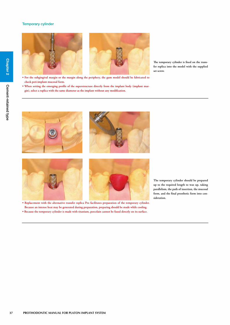
Temporary cylinder
The temporary cylinder should be prepared up to the required length to wax up, taking parallelism, the path of insertion, the mucosal form, and the final prosthetic form into con-sideration.
• Replacement with the alternative transfer replica Pro facilitates preparation of the temporary cylinder. Because an intense heat may be generated during preparation, preparing should be made while cooling.
• Because the temporary cylinder is made with titanium, porcelain cannot be fused directly on its surface.
The temporary cylinder is fixed on the trans-fer replica into the model with the supplied set screw.
• For the subgingival margin or the margin along the periphery, the gum model should be fabricated to check peri-implant mucosal form.
• When setting the emerging profile of the superstructure directly from the implant body (implant mar-gin), select a replica with the same diameter as the implant without any modification.

Chap
ter 2
38 PROTHODONTIC MANUAL FOR PLATON IMPLANT SYSTEM
Cem
ent-retained typ
e
Torque control is performed with a torque ratchet. The recommended tightening torque is in the range of 25 to 30N.
• After insertion of the temporary restoration into the mouth, the recommendation is to fill the screw hole with pledget and resin.
The core should be taken with a commercial silicone impression material to pack resin.
• Sandblasting the surface of the retention surface is recommended to increase retention of cement.• Be careful not to fill in the access hole while packing resin.

Chap
ter 2C
ement-retained
type
39 PROTHODONTIC MANUAL FOR PLATON IMPLANT SYSTEM
Gold cylinder
The plastic part is prepared up to the required length to wax up, taking parallelism, the path of insertion, the mucosal form, and the final prosthetic form consideration. Wax-up should be made with due attention to clearance with the opposite tooth, securement of the access hole, and attachment of wax to the interface part.
• Replacement with the alternative transfer replica facilitates preparation and wax-up of the plastic part. Because an intense heat may be generated during preparation, preparing should be made while cooling.
• The gold cylinder Pro is made with plastic and non-oxygenated high-temperature molten alloy. Wax-up should be directly made on the cylinder to cast-joint.
• Fusion of non-oxygenated alloy and casting metal after casting completes the abutment. Because the non-oxygenated alloy part interfaces with the implant, preparation or adjustment may have an effect on the interlocking accuracy.
• Be aware that porcelain cannot be bonded directly on the surface of gold cylinder. When porcelain is fused, a commercial porcelain-fused alloy should be cast-jointed.
The Gold cylinder is fixed on the transfer replica into the model with the supplied set screw.
• For the subgingival margin or the margin along the periphery, the gum model should be fabricated to check peri-implant mucosal form.
• When setting the emerging profile of the superstructure directly from the implant body (implant mar-gin), select a replica with the same diameter as the implant without any modification.

Chap
ter 2
40 PROTHODONTIC MANUAL FOR PLATON IMPLANT SYSTEM
Cem
ent-retained typ
e
After wax-up, the access hole and interface should be carefully cleaned under a micro-scope. The recommendation is to sprue so that the access hole turns up to avoid air entrapment in the screw access hole during investment. The investment must be suitable to cast-joint. The heating schedule for the ring should be increased to slower than usual to obtain a better joint between the gold cyl-inder and the alloy. Also, a longer preheating time is recommended. After cast-joint, the cast ring should be slowly cooled to excavate the casting. Residual investment attached to the interface of the gold cylinder should be carefully excavated to avoid the damage to the interface.
◎ To selection the optimal alloy for cast-joint, the following points should be considered: • An alloy to be used for cast-joint requires a high percentage of gold (more than 75%).• The melting temperature of the alloy must not melt the gold cylinder. (Melting temperature of gold cylinder : 1400 to 1490°C) (Melting temperature of alloy suitable to cast joint: lower than 1250°C)• The gold cylinder should be sufficiently heated prior to cast joint.• Once the alloy is melted, casting should be made quickly.
The casting is excavated from the investment to microscopically check for air entrapment at the interface and the access hole. If necessary, adaptation of the casting should be verified. When adaptation of the superstructure to the connected units is not improved, measures such as soldering should be taken after cut-ting because the framework may deform.
• Because any damage to the interface by sandblasting or instrument use may cause improper fitting, do not touch the interface part.
• Do not touch the interface during polishing. Replacement with the alternative transfer replica facilitates polishing.

Chap
ter 2C
ement-retained
type
41 PROTHODONTIC MANUAL FOR PLATON IMPLANT SYSTEM
Torque control is performed with a torque ratchet. The recommended tightening torque is in the range of 25 to 30N.
• After insertion of the abutment into the mouth, the recommendation is to fill the screw hole with pledget and resin.
• Sandblasting the surface of the abutment is recommended to increase retention of cement.
The transfer index should be fabricated with pattern resin to ensure replacement of the abutment by cast joint into the mouth.
• The transfer index should be fabricated to avoid deformation by torque and to keep the abutment from moving.