Embed Size (px)
Citation preview

Force-displacement relationship modelling ofmasonry in�lled walls with openings in hinged steelframesHaoran Zuo ( [email protected] )
The Hong Kong Polytechnic UniversityWeiping Zhang
Tongji University College of Civil EngineeringBaotong Wang
Tongji University College of Civil EngineeringXianglin Gu
Tongji University College of Civil Engineering
Research Article
Keywords: Force-displacement relationship, masonry in�ll, aspect ratio, vertical load, opening, hingedsteel frame
Posted Date: April 30th, 2021
DOI: https://doi.org/10.21203/rs.3.rs-460695/v1
License: This work is licensed under a Creative Commons Attribution 4.0 International License. Read Full License
1
Force-displacement relationship modelling of masonry infilled walls 1
with openings in hinged steel frames 2
Haoran Zuo, Weiping Zhang*, Baotong Wang, Xianglin Gu 3
Key Laboratory of Performance Evolution and Control for Engineering Structures of Ministry of 4
Education, Tongji University, Shanghai, 200092, China 5
*Corresponding author 6
E-mail address: [email protected] (W. Zhang) 7
8
ABSTRACT 9
Seismic behaviour of masonry infilled frames has attracted extensive attentions from researchers, and it 10
was found that infills normally experienced a diagonal compression under lateral loading. Infill was 11
therefore assumed as an equivalent diagonal strut in structural response estimations of infilled frames, and 12
a force-displacement curve was adopted to describe the mechanical properties of the strut. However, the 13
influences of infill aspect ratio, vertical load acting on the surrounding frames, and opening were not 14
systematically addressed in establishing the force-displacement relationship of infills. To investigate the 15
effects of these influential parameters on the lateral responses of infilled walls including initial stiffness and 16
strength, detailed three-dimensional finite element (FE) models of masonry infilled hinged steel frames are 17
developed in ABAQUS in the present study, and a wide parametric study with respect to various aspect 18
ratios, vertical loads, and opening sizes and locations is performed. A generalized force-displacement 19
relationship model of infilled walls is proposed based on regression analyses of numerical results. The 20
efficacy of the proposed model is examined by using the existing experimental test results, and it shows 21
that the model can accurately predict the lateral stiffness and load carrying capacity of infilled walls and 22
thus has great potential applications in structural designs and analyses for masonry infilled steel frames. 23
Keywords: Force-displacement relationship, masonry infill, aspect ratio, vertical load, opening, hinged 24
steel frame 25
26
1. Introduction 27
Masonry infills are commonly used as either interior partitions or exterior claddings in reinforced concrete 28
(RC) and steel framed structures, which are still the widespread structural types around the world. Due to 29
the unpredictable failure characteristics and highly variable material properties of masonry infills, they are 30
only considered as gravity loads in the current design practices, and the surrounding frames are designed 31
2
against external excitations such as wind and seismic loads by neglecting the interaction between the infills 32
and bounding frames. However, the expected behaviour of framed structures, namely seismic demand, 33
seismic capacity, and failure modes, could be significantly changed by the presence of infills. Therefore, 34
simplifying the frames and infills as structural and non-structural elements cannot accurately capture the 35
effects induced by the infills, and it is important and necessary to implement a comprehensive study on the 36
structural responses of framed structures considering the influences of infilled walls. 37
Over the past several decades, extensive experimental research works have been carried out to investigate 38
the seismic behaviour of infilled frames especially for RC structures (e.g., (Alwashali et al. 2019; Cavaleri 39
and Di Trapani 2014; Morandi et al. 2018)). In the experimental tests of infilled steel frames, some 40
influential parameters were studied, and the test results showed that the structural stiffness and strength 41
were significantly related to the rigidity of the steel beam-column connection (Mohammadi and Emami 42
2019) and the connection type between the infill and frame (Liu and Manesh 2013). In addition, infilled 43
steel frames with different masonry brick types exhibited different behaviours with respect to the lateral 44
stiffness, load carrying capacity, and energy dissipation capacity (Markulak et al. 2013). Similar to infilled 45
RC frames (Shing and Mehrabi 2002), El-Dakhakhni et al. (2003) summarized five possible failure modes 46
of infilled steel frames, and only the corner crushing and sliding shear failure modes were of practical 47
importance. 48
Instead of conducting experimental tests, some researchers adopted numerical methods to estimate the 49
seismic responses of framed structures with infills. These methods are referred to as micro- (Asteris et al. 50
2013) and macro-modelling (Asteris et al. 2011; Di Trapani et al. 2015) strategies. In the micro-modelling 51
approach (Asteris et al. 2013), the masonry bricks and mortar joints were explicitly modelled, or the infill 52
was assumed as a homogeneous and isotropic continuum. This approach can simulate both the global 53
structural responses of infilled frames and the local damages (e.g., cracks) of infills under the lateral loading 54
by sacrificing large computational time, which would hinder its wide applications in the structural analyses 55
and designs of infilled frames. 56
On the other hand, it has been recognized that the infill mainly experiences a compression along the 57
diagonal direction under the lateral load. Polyakov (1960) proposed an idea that using an equivalent 58
diagonal strut to represent the infill, which can be deemed as a macro-modelling approach to consider the 59
infill effects (Asteris et al. 2011; Di Trapani et al. 2015) and have been adopted in the structural response 60
analyses of infilled frames (e.g., (Cavaleri et al. 2017; Gentile et al. 2019; Perrone et al. 2017)). In the 61
macro-modelling approach (i.e., the diagonal strut model), the critical parameter is the determination of the 62
strut width, and different researchers proposed different formulas to calculate the strut width (Klingner and 63
Bertero 1978; Liauw and Kwan 1984; Mainstone 1971). However, a constant strut width cannot consider 64

3
the stiffness and strength variations of infills with increasing the lateral load, and a force-displacement 65
curve is required to fully describe the stiffness and strength softening during the whole loading process 66
(Benavent-Climent et al. 2018; Cavaleri and Di Trapani 2014; Di Trapani et al. 2020; Dolšek and Fajfar 67
2008; Uva et al. 2012a, b). 68
In the development of the force-displacement relationship of the diagonal strut, it should be noted that the 69
influences of infill aspect ratio, vertical load on the structure, and opening were less researched. Papia et al. 70
(2003) used an equivalent criterion between the initial stiffness of the actual infilled frame and of the 71
diagonal strut model to calculate the strut width, and they concluded that the strut width was associated 72
with the infill aspect ratio although only two different aspect ratios (1.0 and 1.5) were investigated in their 73
study. Regarding the effect of vertical load on the in-plane behaviour of infilled frames, the axial load could 74
increase the initial stiffness and structural strength while decrease the structural ductility, which has 75
experimentally confirmed by Liu and Manesh (2013). Later, Campione et al. (2015), and Chen and Liu 76
(2016) quantified the effect of vertical load on the initial stiffness and lateral resistance of infilled walls. 77
Furthermore, the openings like windows and doors are usually designed in infills for architectural functions, 78
and it has been demonstrated that the openings could reduce the lateral stiffness and strength of infilled 79
frames (Kakaletsis and Karayannis 2008; Morandi et al. 2018). Tasnimi and Mohebkhah (2011) used the 80
reduction factors to consider the influence of opening, which normally can be obtained from the statistical 81
regression analyses of experimental test results (Humayun Basha et al. 2020; Mohammadi and Nikfar 2013). 82
However, only the central openings were investigated in the above-mentioned studies (Humayun Basha et 83
al. 2020; Mohammadi and Nikfar 2013; Tasnimi and Mohebkhah 2011). Chen and Liu (2015) performed a 84
parametric study to investigate the influences of opening size and location on the in-plane behaviour of 85
infilled steel frames, and the numerical results showed that the degree of the reduction on the lateral stiffness 86
and strength of infilled walls was related to the opening size as well as the opening location. To the best 87
knowledge of the authors, the combined influences of infill aspect ratio, vertical load, and opening size and 88
location on the force-displacement relationship of infills have not been reported in the open literature. 89
In a companion paper of the authors (Zuo et al. 2021), the in-plane behaviour of masonry infilled hinged 90
steel frames (MIHSFs) without and with openings were investigated under cyclic loading tests, and three-91
dimensional (3D) finite element (FE) models of the test specimens were developed in ABAQUS. As an 92
extension of that work, the present study aims to further conduct a comprehensive study to investigate the 93
effects of infill aspect ratio, vertical load and opening on the in-plane responses of infilled walls in hinged 94
steel frames (HSFs), and a generalized force-displacement relationship model for infills will be proposed 95
based on regression analyses of numerical results, which will be validated using the available experimental 96
test results. 97
4
2. Brief review of FE model 98
The prototype structure of MIHSFs adopted in the present study is a historical building in Shanghai, China, 99
and its detailed information can be found in Gu et al. (2018), which is not repetitively introduced here for 100
conciseness. Moreover, the FE models of 1/2 scaled MIHSFs were developed and validated in the authors’ 101
previous study (Zuo et al. 2021), and they are briefly reviewed in this section for the sake of completeness. 102
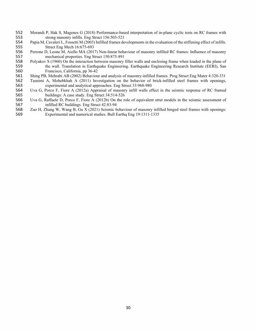
Solid elements (C3D8R element) are used to model the surrounding frame including the steel beam, steel 103
columns, T-shaped concrete beam and masonry columns, and the concrete foundation beam. For the infilled 104
wall, a simplified micro-modelling technique is adopted where the infilled wall is homogenized as one-105
phase material and modelled by the continuum elements (C3D8R element) instead of developing the clay 106
bricks and mortar joints explicitly. This modelling approach is adopted because the primary objective of 107
the present study is to investigate the global response (i.e., the lateral force-displacement relationship) of 108
the infilled wall under the lateral load, and a high-fidelity FE model is normally required when the local 109
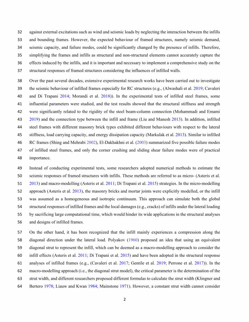
response (e.g., crack pattern) of the infilled wall is of interest. Fig. 1 shows a schematic of the FE model of 110
MIHSFs. 111
112
Fig. 1. FE model of MIHSFs 113
A normal contact and a tangential contact are adopted to model the interaction between the infill and 114
bounding frame in the FE models. The normal contact behaviour is simulated by a hard contact in ABAQUS, 115
in which the surfaces of the infill and frame can separate without any tensile resistance while the 116
compressive forces will be generated when the surfaces are in a tight contact. In addition, the Coulomb 117
5
friction is defined to model the tangential contact behaviour between the infill and frame, and the friction 118
coefficient is set as 0.7 (GB50003 2011). 119
The nonlinear behaviour of concrete and masonry materials can be described by using the concrete damage 120
plasticity (CDP) model in ABAQUS. In the CDP model, the plasticity parameters (ψ, e, σb0/ σc0, Kc, and μ) 121
and the uniaxial constitutive laws in compression and tension are needed. The values of the plasticity 122
parameters recommended in other literature (e.g., (Li et al. 2019)) are adopted in the present study, which 123
are 30, 0.1, 1.16, 0.6667, and 0.0001, respectively. The compressive and tensile stress-strain relationships 124
of the concrete and masonry materials are obtained from the design codes of concrete and masonry 125
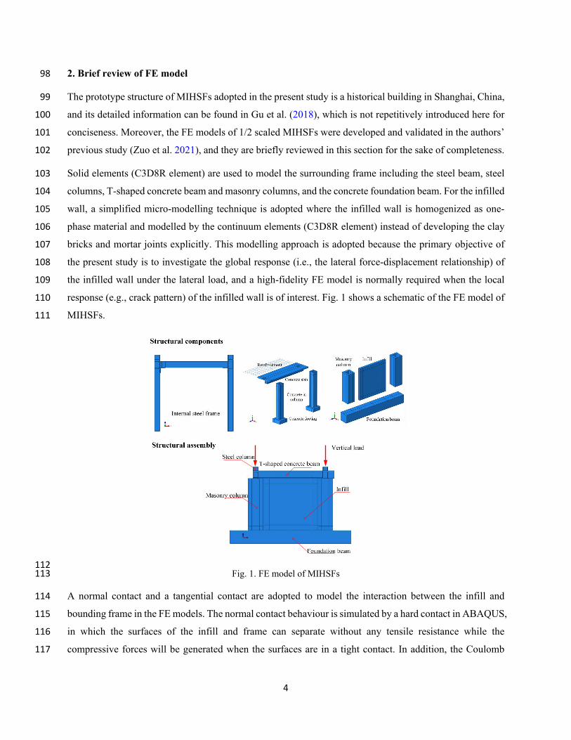
structures (GB50010 2010; GB50003 2011), and Table 1 tabulates the compressive strength and Young’s 126
modulus of the concrete and masonry materials. 127
As for the steel material, the Young’s modulus and tensile stress-strain curve are defined to model its elastic 128
and plastic behaviour, which are measured from the material testing, and a Poisson ratio of 0.3 is also 129
defined. The characteristic strengths and elastic modulus of the steel material are also given in Table 1. It 130
should be noted that the values in this table are the average results of three measured samples, and the 131
elastic modulus of rebar is abnormally lower than that of steel frame; however, which are in the concrete 132
slab, and the structural responses are mainly governed by the steel frame and infilled wall. 133
Table 1 Material properties of concrete, masonry and steel (Gu et al. 2018) 134
Material Compressive strength (MPa) Shear bond strength (MPa) Elastic modulus (×104 MPa)
Concrete 18.6 - 2.5
Masonry 2.95 0.27 0.34
Material Yield strength (MPa) Ultimate strength (MPa) Elastic modulus (×105 MPa)
Steel beam 274 385 1.82
Steel column 261 374 1.73
Steel plate 278 442 2.18
Rebar 281 476 1.61
135
In the FE models, all the degrees-of-freedom of the foundation beam are restricted to simulate the fixed 136
boundary condition in practice. To investigate the in-plane responses of MIHSFs, three loading steps are 137
defined, which are the gravity, axial, and lateral loads, respectively. A gravitational acceleration of 9.8 m/s2 138
is applied to consider the self-weight of MIHSFs; a surface pressure is loaded at the top of each column to 139
simulate the axial load acting on the surrounding frames; and a displacement-controlled lateral load of 50 140
mm is imposed to the FE models. 141
142
143
6
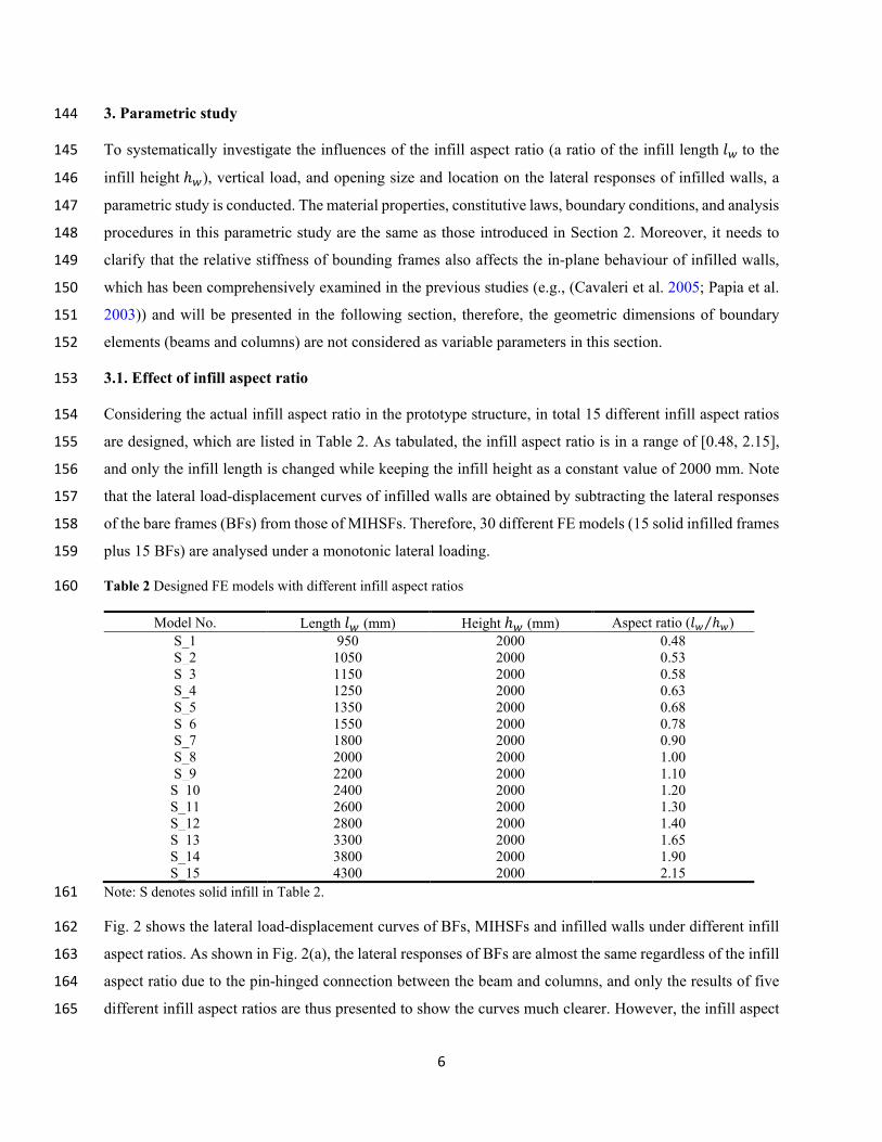
3. Parametric study 144
To systematically investigate the influences of the infill aspect ratio (a ratio of the infill length 𝑙𝑙𝑤𝑤 to the 145
infill height ℎ𝑤𝑤), vertical load, and opening size and location on the lateral responses of infilled walls, a 146
parametric study is conducted. The material properties, constitutive laws, boundary conditions, and analysis 147
procedures in this parametric study are the same as those introduced in Section 2. Moreover, it needs to 148
clarify that the relative stiffness of bounding frames also affects the in-plane behaviour of infilled walls, 149
which has been comprehensively examined in the previous studies (e.g., (Cavaleri et al. 2005; Papia et al. 150
2003)) and will be presented in the following section, therefore, the geometric dimensions of boundary 151
elements (beams and columns) are not considered as variable parameters in this section. 152
3.1. Effect of infill aspect ratio 153
Considering the actual infill aspect ratio in the prototype structure, in total 15 different infill aspect ratios 154
are designed, which are listed in Table 2. As tabulated, the infill aspect ratio is in a range of [0.48, 2.15], 155
and only the infill length is changed while keeping the infill height as a constant value of 2000 mm. Note 156
that the lateral load-displacement curves of infilled walls are obtained by subtracting the lateral responses 157
of the bare frames (BFs) from those of MIHSFs. Therefore, 30 different FE models (15 solid infilled frames 158
plus 15 BFs) are analysed under a monotonic lateral loading. 159
Table 2 Designed FE models with different infill aspect ratios 160
Model No. Length 𝑙𝑙𝑤𝑤 (mm) Height ℎ𝑤𝑤 (mm) Aspect ratio (𝑙𝑙𝑤𝑤 ℎ𝑤𝑤⁄ )
S_1 950 2000 0.48
S_2 1050 2000 0.53
S_3 1150 2000 0.58
S_4 1250 2000 0.63
S_5 1350 2000 0.68
S_6 1550 2000 0.78
S_7 1800 2000 0.90
S_8 2000 2000 1.00
S_9 2200 2000 1.10
S_10 2400 2000 1.20
S_11 2600 2000 1.30
S_12 2800 2000 1.40
S_13 3300 2000 1.65
S_14 3800 2000 1.90
S_15 4300 2000 2.15
Note: S denotes solid infill in Table 2. 161
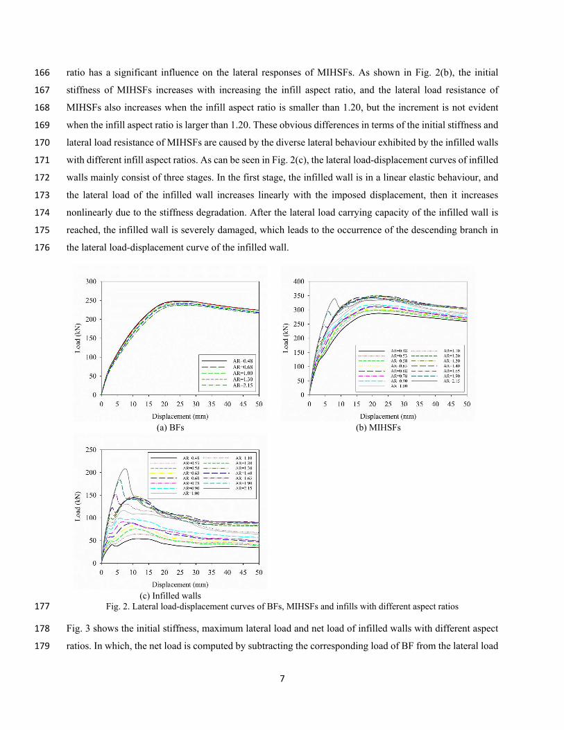
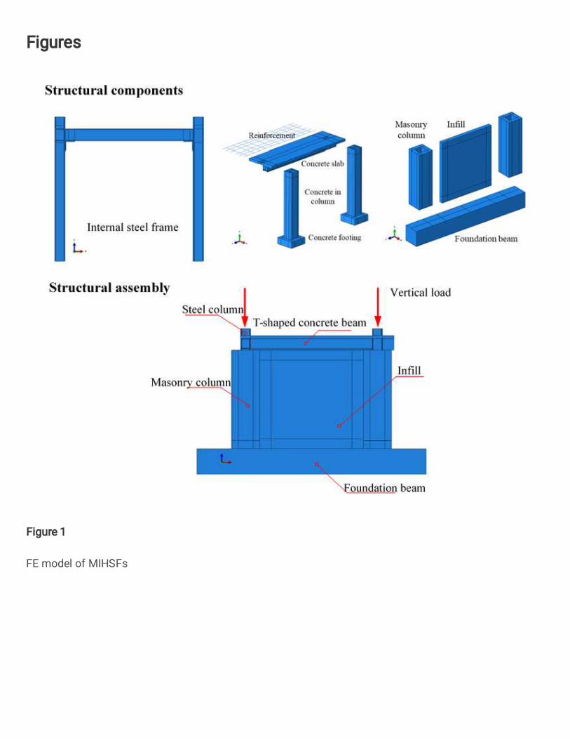
Fig. 2 shows the lateral load-displacement curves of BFs, MIHSFs and infilled walls under different infill 162
aspect ratios. As shown in Fig. 2(a), the lateral responses of BFs are almost the same regardless of the infill 163
aspect ratio due to the pin-hinged connection between the beam and columns, and only the results of five 164
different infill aspect ratios are thus presented to show the curves much clearer. However, the infill aspect 165
7
ratio has a significant influence on the lateral responses of MIHSFs. As shown in Fig. 2(b), the initial 166
stiffness of MIHSFs increases with increasing the infill aspect ratio, and the lateral load resistance of 167
MIHSFs also increases when the infill aspect ratio is smaller than 1.20, but the increment is not evident 168
when the infill aspect ratio is larger than 1.20. These obvious differences in terms of the initial stiffness and 169
lateral load resistance of MIHSFs are caused by the diverse lateral behaviour exhibited by the infilled walls 170
with different infill aspect ratios. As can be seen in Fig. 2(c), the lateral load-displacement curves of infilled 171
walls mainly consist of three stages. In the first stage, the infilled wall is in a linear elastic behaviour, and 172
the lateral load of the infilled wall increases linearly with the imposed displacement, then it increases 173
nonlinearly due to the stiffness degradation. After the lateral load carrying capacity of the infilled wall is 174
reached, the infilled wall is severely damaged, which leads to the occurrence of the descending branch in 175
the lateral load-displacement curve of the infilled wall. 176
(a) BFs (b) MIHSFs
(c) Infilled walls
Fig. 2. Lateral load-displacement curves of BFs, MIHSFs and infills with different aspect ratios 177
Fig. 3 shows the initial stiffness, maximum lateral load and net load of infilled walls with different aspect 178
ratios. In which, the net load is computed by subtracting the corresponding load of BF from the lateral load 179
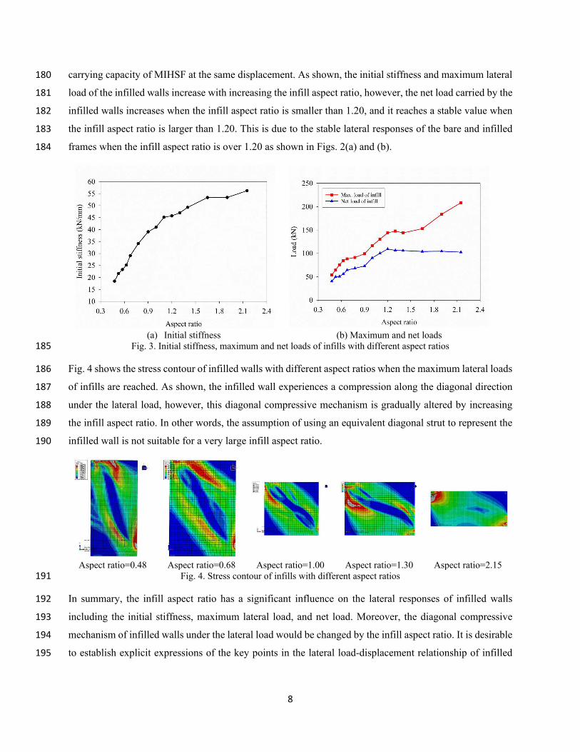
8
carrying capacity of MIHSF at the same displacement. As shown, the initial stiffness and maximum lateral 180
load of the infilled walls increase with increasing the infill aspect ratio, however, the net load carried by the 181
infilled walls increases when the infill aspect ratio is smaller than 1.20, and it reaches a stable value when 182
the infill aspect ratio is larger than 1.20. This is due to the stable lateral responses of the bare and infilled 183
frames when the infill aspect ratio is over 1.20 as shown in Figs. 2(a) and (b). 184
(a) Initial stiffness (b) Maximum and net loads
Fig. 3. Initial stiffness, maximum and net loads of infills with different aspect ratios 185
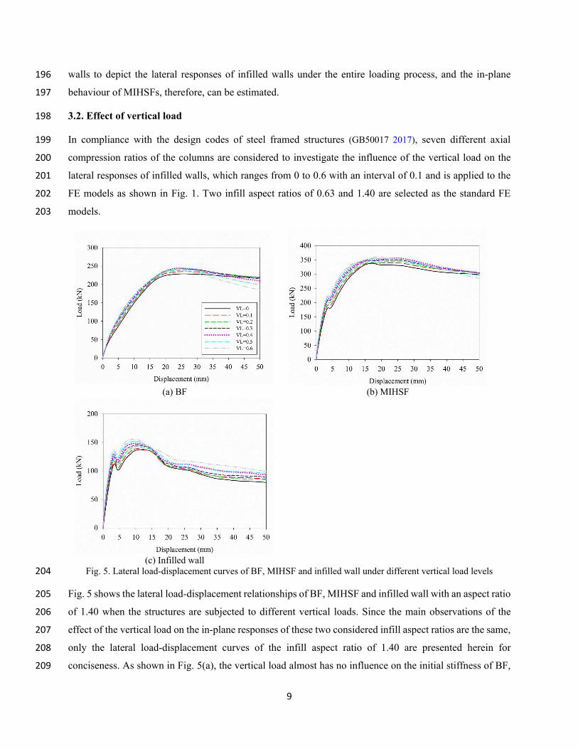
Fig. 4 shows the stress contour of infilled walls with different aspect ratios when the maximum lateral loads 186
of infills are reached. As shown, the infilled wall experiences a compression along the diagonal direction 187
under the lateral load, however, this diagonal compressive mechanism is gradually altered by increasing 188
the infill aspect ratio. In other words, the assumption of using an equivalent diagonal strut to represent the 189
infilled wall is not suitable for a very large infill aspect ratio. 190
Aspect ratio=0.48 Aspect ratio=0.68 Aspect ratio=1.00 Aspect ratio=1.30 Aspect ratio=2.15
Fig. 4. Stress contour of infills with different aspect ratios 191
In summary, the infill aspect ratio has a significant influence on the lateral responses of infilled walls 192
including the initial stiffness, maximum lateral load, and net load. Moreover, the diagonal compressive 193
mechanism of infilled walls under the lateral load would be changed by the infill aspect ratio. It is desirable 194
to establish explicit expressions of the key points in the lateral load-displacement relationship of infilled 195
9
walls to depict the lateral responses of infilled walls under the entire loading process, and the in-plane 196
behaviour of MIHSFs, therefore, can be estimated. 197
3.2. Effect of vertical load 198
In compliance with the design codes of steel framed structures (GB50017 2017), seven different axial 199
compression ratios of the columns are considered to investigate the influence of the vertical load on the 200
lateral responses of infilled walls, which ranges from 0 to 0.6 with an interval of 0.1 and is applied to the 201
FE models as shown in Fig. 1. Two infill aspect ratios of 0.63 and 1.40 are selected as the standard FE 202
models. 203
(a) BF (b) MIHSF
(c) Infilled wall
Fig. 5. Lateral load-displacement curves of BF, MIHSF and infilled wall under different vertical load levels 204
Fig. 5 shows the lateral load-displacement relationships of BF, MIHSF and infilled wall with an aspect ratio 205
of 1.40 when the structures are subjected to different vertical loads. Since the main observations of the 206
effect of the vertical load on the in-plane responses of these two considered infill aspect ratios are the same, 207
only the lateral load-displacement curves of the infill aspect ratio of 1.40 are presented herein for 208
conciseness. As shown in Fig. 5(a), the vertical load almost has no influence on the initial stiffness of BF, 209
10
and the lateral load carrying capacity slightly increases with the increase of the applied vertical load while 210
it slightly decreases when the axial compression ratio is larger than 0.4. With increasing the vertical load, 211
the strength degradation in the lateral load-displacement curves of BF becomes more evident, which 212
indicates that the ductility of BFs is decreased by the vertical load. As for MIHSF and the infilled wall, both 213
initial stiffness and lateral load resistance increase with the vertical load as shown in Figs. 5(b) and (c). This 214
is because the vertical load acting on the columns can enhance the corner constraint effect of the 215
surrounding frame on the infilled wall, which leads to the improvement of the stiffness and strength of the 216
infilled wall. Compared to the infilled wall, the increment of the lateral load carrying capacity of MIHSF 217
induced by the vertical load is limited because of the serious damage of the infill. In other words, the lateral 218
displacements corresponding to the maximum loads of MISHF and the infilled wall are different, and the 219
corresponding displacement of the infilled wall is much smaller than that of MIHSF as shown in Figs. 5(b) 220
and (c). 221
(a) Initial stiffness (b) Maximum load
(c) Net load
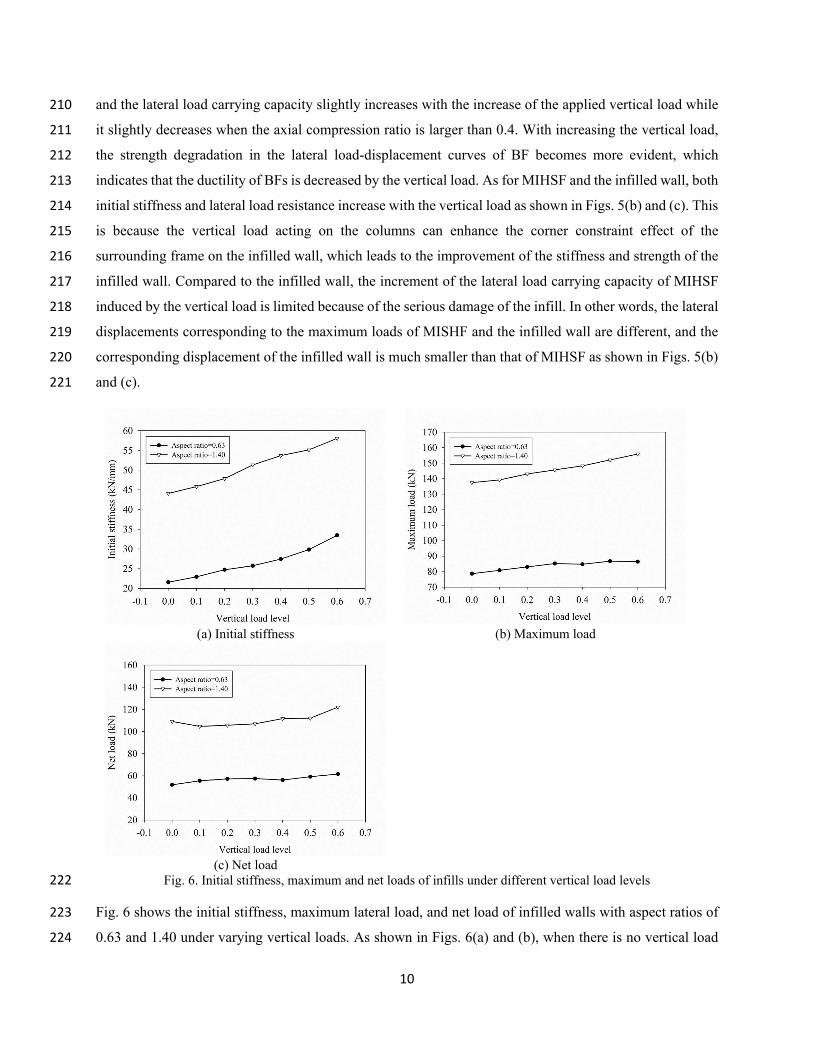
Fig. 6. Initial stiffness, maximum and net loads of infills under different vertical load levels 222
Fig. 6 shows the initial stiffness, maximum lateral load, and net load of infilled walls with aspect ratios of 223
0.63 and 1.40 under varying vertical loads. As shown in Figs. 6(a) and (b), when there is no vertical load 224
11
applied to the structure, the initial stiffness and lateral load carrying capacity of the infilled wall with an 225
aspect ratio of 0.63 are 21.6 kN/mm and 78.7 kN, respectively, and they are 33.5 kN/mm and 88.4 kN when 226
the axial compression ratio is 0.6, which increase by 55.1% and 12.3%, respectively; for the infilled wall 227
with an aspect ratio of 1.40, the initial stiffness and lateral load carrying capacity increase by 31.8% and 228
13.9%, respectively. In general, the initial stiffness and maximum lateral load of infilled walls are affected 229
by the vertical load with different degrees depending on the infill aspect ratio. However, as shown in Fig. 230
6(c), it seems that the vertical load has a negligible effect on the net load of infilled walls. 231
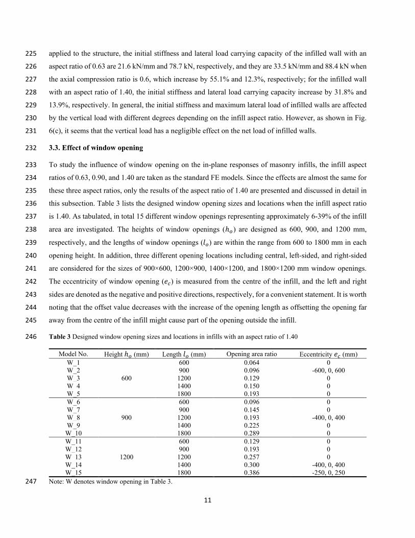
3.3. Effect of window opening 232
To study the influence of window opening on the in-plane responses of masonry infills, the infill aspect 233
ratios of 0.63, 0.90, and 1.40 are taken as the standard FE models. Since the effects are almost the same for 234
these three aspect ratios, only the results of the aspect ratio of 1.40 are presented and discussed in detail in 235
this subsection. Table 3 lists the designed window opening sizes and locations when the infill aspect ratio 236
is 1.40. As tabulated, in total 15 different window openings representing approximately 6-39% of the infill 237
area are investigated. The heights of window openings (ℎ𝑜𝑜) are designed as 600, 900, and 1200 mm, 238
respectively, and the lengths of window openings (𝑙𝑙𝑜𝑜) are within the range from 600 to 1800 mm in each 239
opening height. In addition, three different opening locations including central, left-sided, and right-sided 240
are considered for the sizes of 900×600, 1200×900, 1400×1200, and 1800×1200 mm window openings. 241
The eccentricity of window opening (𝑒𝑒𝑐𝑐) is measured from the centre of the infill, and the left and right 242
sides are denoted as the negative and positive directions, respectively, for a convenient statement. It is worth 243
noting that the offset value decreases with the increase of the opening length as offsetting the opening far 244
away from the centre of the infill might cause part of the opening outside the infill. 245
Table 3 Designed window opening sizes and locations in infills with an aspect ratio of 1.40 246
Model No. Height ℎ𝑜𝑜 (mm) Length 𝑙𝑙𝑜𝑜 (mm) Opening area ratio Eccentricity 𝑒𝑒𝑐𝑐 (mm)
W_1
600
600 0.064 0
W_2 900 0.096 -600, 0, 600
W_3 1200 0.129 0
W_4 1400 0.150 0
W_5 1800 0.193 0
W_6
900
600 0.096 0
W_7 900 0.145 0
W_8 1200 0.193 -400, 0, 400
W_9 1400 0.225 0
W_10 1800 0.289 0
W_11
1200
600 0.129 0
W_12 900 0.193 0
W_13 1200 0.257 0
W_14 1400 0.300 -400, 0, 400
W_15 1800 0.386 -250, 0, 250
Note: W denotes window opening in Table 3. 247
12
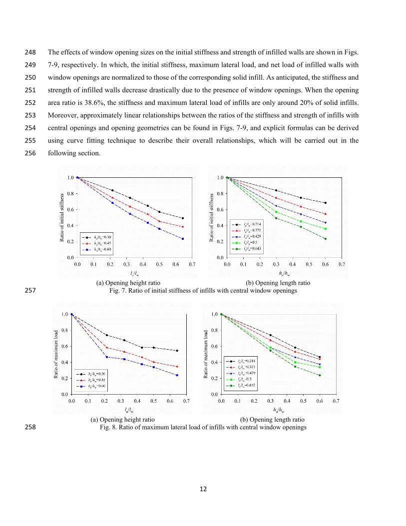
The effects of window opening sizes on the initial stiffness and strength of infilled walls are shown in Figs. 248
7-9, respectively. In which, the initial stiffness, maximum lateral load, and net load of infilled walls with 249
window openings are normalized to those of the corresponding solid infill. As anticipated, the stiffness and 250
strength of infilled walls decrease drastically due to the presence of window openings. When the opening 251
area ratio is 38.6%, the stiffness and maximum lateral load of infills are only around 20% of solid infills. 252
Moreover, approximately linear relationships between the ratios of the stiffness and strength of infills with 253
central openings and opening geometries can be found in Figs. 7-9, and explicit formulas can be derived 254
using curve fitting technique to describe their overall relationships, which will be carried out in the 255
following section. 256
(a) Opening height ratio (b) Opening length ratio
Fig. 7. Ratio of initial stiffness of infills with central window openings 257
(a) Opening height ratio (b) Opening length ratio
Fig. 8. Ratio of maximum lateral load of infills with central window openings 258
13
(a) Opening height ratio (b) Opening length ratio
Fig. 9. Ratio of net load of infills with central window openings 259
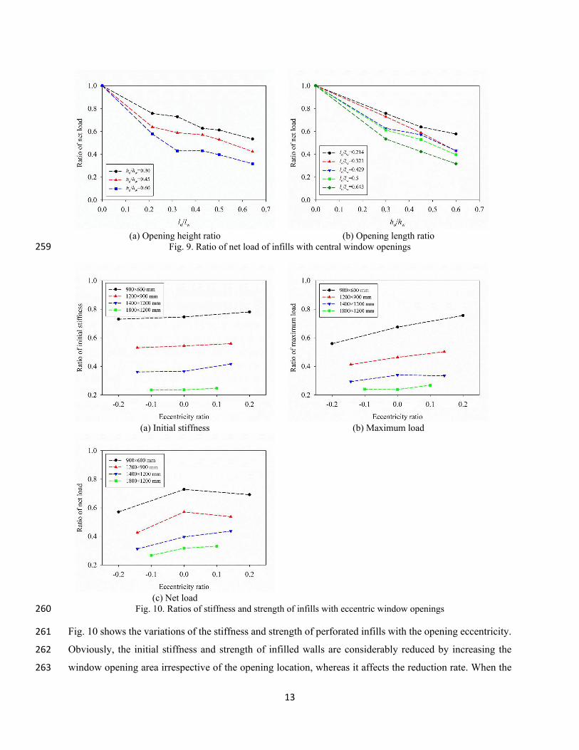
(a) Initial stiffness (b) Maximum load
(c) Net load
Fig. 10. Ratios of stiffness and strength of infills with eccentric window openings 260
Fig. 10 shows the variations of the stiffness and strength of perforated infills with the opening eccentricity. 261
Obviously, the initial stiffness and strength of infilled walls are considerably reduced by increasing the 262
window opening area irrespective of the opening location, whereas it affects the reduction rate. When the 263
14
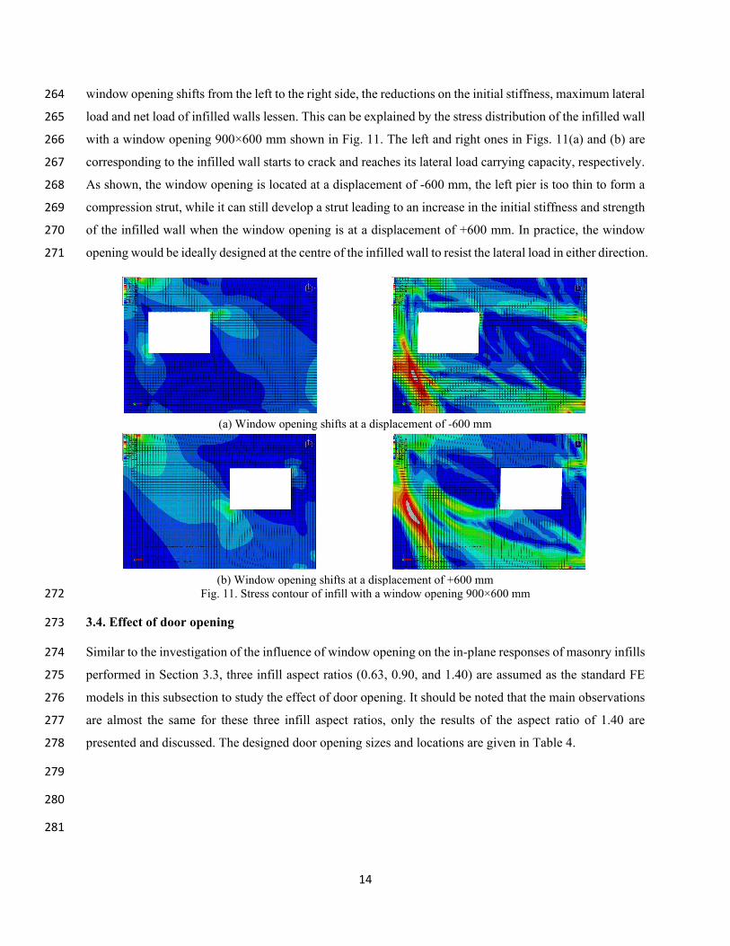
window opening shifts from the left to the right side, the reductions on the initial stiffness, maximum lateral 264
load and net load of infilled walls lessen. This can be explained by the stress distribution of the infilled wall 265
with a window opening 900×600 mm shown in Fig. 11. The left and right ones in Figs. 11(a) and (b) are 266
corresponding to the infilled wall starts to crack and reaches its lateral load carrying capacity, respectively. 267
As shown, the window opening is located at a displacement of -600 mm, the left pier is too thin to form a 268
compression strut, while it can still develop a strut leading to an increase in the initial stiffness and strength 269
of the infilled wall when the window opening is at a displacement of +600 mm. In practice, the window 270
opening would be ideally designed at the centre of the infilled wall to resist the lateral load in either direction. 271
(a) Window opening shifts at a displacement of -600 mm
(b) Window opening shifts at a displacement of +600 mm
Fig. 11. Stress contour of infill with a window opening 900×600 mm 272
3.4. Effect of door opening 273
Similar to the investigation of the influence of window opening on the in-plane responses of masonry infills 274
performed in Section 3.3, three infill aspect ratios (0.63, 0.90, and 1.40) are assumed as the standard FE 275
models in this subsection to study the effect of door opening. It should be noted that the main observations 276
are almost the same for these three infill aspect ratios, only the results of the aspect ratio of 1.40 are 277
presented and discussed. The designed door opening sizes and locations are given in Table 4. 278
279
280
281
15
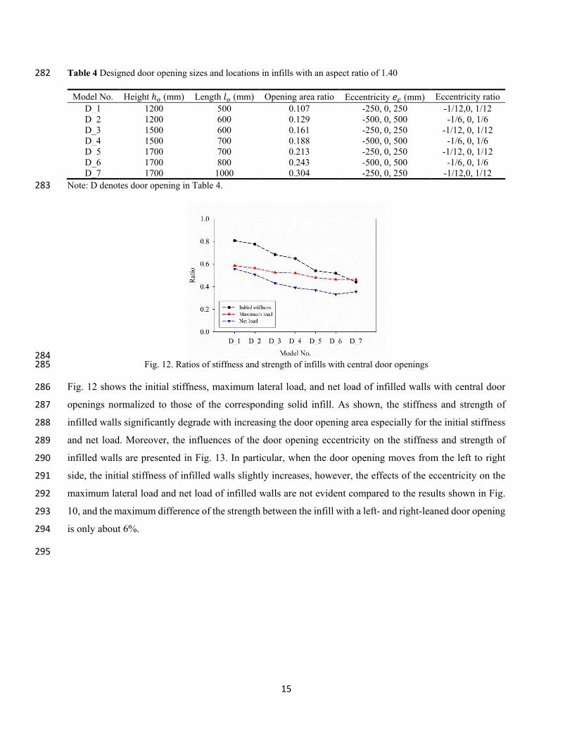
Table 4 Designed door opening sizes and locations in infills with an aspect ratio of 1.40 282
Model No. Height ℎ𝑜𝑜 (mm) Length 𝑙𝑙𝑜𝑜 (mm) Opening area ratio Eccentricity 𝑒𝑒𝑐𝑐 (mm) Eccentricity ratio
D_1 1200 500 0.107 -250, 0, 250 -1/12,0, 1/12
D_2 1200 600 0.129 -500, 0, 500 -1/6, 0, 1/6
D_3 1500 600 0.161 -250, 0, 250 -1/12, 0, 1/12
D_4 1500 700 0.188 -500, 0, 500 -1/6, 0, 1/6
D_5 1700 700 0.213 -250, 0, 250 -1/12, 0, 1/12
D_6 1700 800 0.243 -500, 0, 500 -1/6, 0, 1/6
D_7 1700 1000 0.304 -250, 0, 250 -1/12,0, 1/12
Note: D denotes door opening in Table 4. 283
284
Fig. 12. Ratios of stiffness and strength of infills with central door openings 285
Fig. 12 shows the initial stiffness, maximum lateral load, and net load of infilled walls with central door 286
openings normalized to those of the corresponding solid infill. As shown, the stiffness and strength of 287
infilled walls significantly degrade with increasing the door opening area especially for the initial stiffness 288
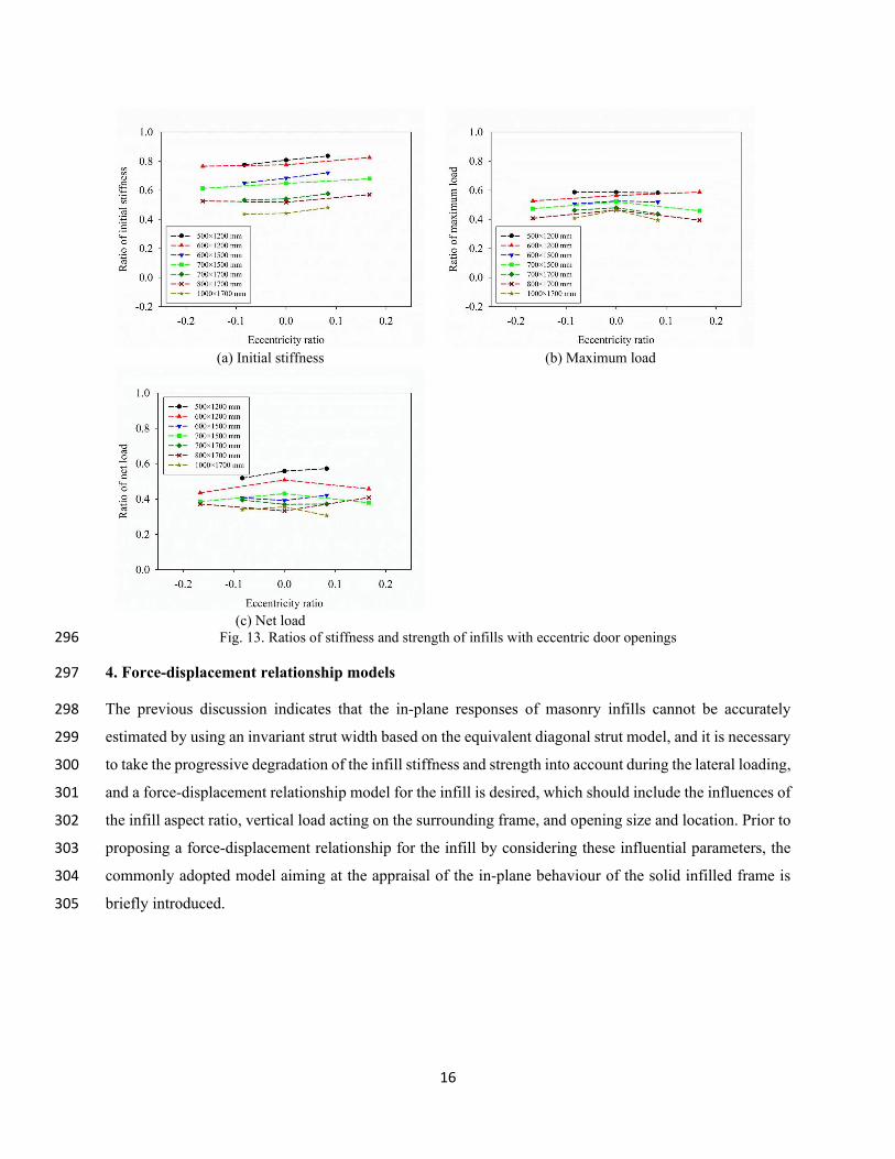
and net load. Moreover, the influences of the door opening eccentricity on the stiffness and strength of 289
infilled walls are presented in Fig. 13. In particular, when the door opening moves from the left to right 290
side, the initial stiffness of infilled walls slightly increases, however, the effects of the eccentricity on the 291
maximum lateral load and net load of infilled walls are not evident compared to the results shown in Fig. 292
10, and the maximum difference of the strength between the infill with a left- and right-leaned door opening 293
is only about 6%. 294
295
16
(a) Initial stiffness (b) Maximum load
(c) Net load
Fig. 13. Ratios of stiffness and strength of infills with eccentric door openings 296
4. Force-displacement relationship models 297
The previous discussion indicates that the in-plane responses of masonry infills cannot be accurately 298
estimated by using an invariant strut width based on the equivalent diagonal strut model, and it is necessary 299
to take the progressive degradation of the infill stiffness and strength into account during the lateral loading, 300
and a force-displacement relationship model for the infill is desired, which should include the influences of 301
the infill aspect ratio, vertical load acting on the surrounding frame, and opening size and location. Prior to 302
proposing a force-displacement relationship for the infill by considering these influential parameters, the 303
commonly adopted model aiming at the appraisal of the in-plane behaviour of the solid infilled frame is 304
briefly introduced. 305
17
306
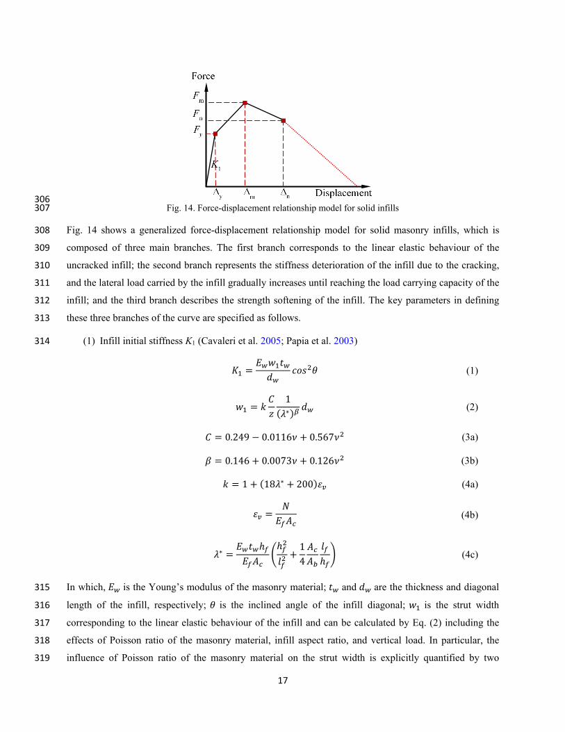
Fig. 14. Force-displacement relationship model for solid infills 307
Fig. 14 shows a generalized force-displacement relationship model for solid masonry infills, which is 308
composed of three main branches. The first branch corresponds to the linear elastic behaviour of the 309
uncracked infill; the second branch represents the stiffness deterioration of the infill due to the cracking, 310
and the lateral load carried by the infill gradually increases until reaching the load carrying capacity of the 311
infill; and the third branch describes the strength softening of the infill. The key parameters in defining 312
these three branches of the curve are specified as follows. 313
(1) Infill initial stiffness K1 (Cavaleri et al. 2005; Papia et al. 2003) 314
𝐾𝐾1 =𝐸𝐸𝑤𝑤𝑤𝑤1𝑡𝑡𝑤𝑤𝑑𝑑𝑤𝑤 𝑐𝑐𝑐𝑐𝑐𝑐2𝜃𝜃 (1)
𝑤𝑤1 = 𝑘𝑘 𝐶𝐶𝑧𝑧 1
(𝜆𝜆∗)𝛽𝛽 𝑑𝑑𝑤𝑤 (2)
𝐶𝐶 = 0.249 − 0.0116𝜈𝜈 + 0.567𝜈𝜈2 (3a)
𝛽𝛽 = 0.146 + 0.0073𝜈𝜈 + 0.126𝜈𝜈2 (3b)
𝑘𝑘 = 1 + (18𝜆𝜆∗ + 200)𝜀𝜀𝑣𝑣 (4a)
𝜀𝜀𝑣𝑣 =𝑁𝑁𝐸𝐸𝑓𝑓𝐴𝐴𝑐𝑐 (4b)
𝜆𝜆∗ =𝐸𝐸𝑤𝑤𝑡𝑡𝑤𝑤ℎ𝑓𝑓𝐸𝐸𝑓𝑓𝐴𝐴𝑐𝑐 �ℎ𝑓𝑓2𝑙𝑙𝑓𝑓2 +
1
4
𝐴𝐴𝑐𝑐𝐴𝐴𝑏𝑏 𝑙𝑙𝑓𝑓ℎ𝑓𝑓� (4c)
In which, 𝐸𝐸𝑤𝑤 is the Young’s modulus of the masonry material; 𝑡𝑡𝑤𝑤 and 𝑑𝑑𝑤𝑤 are the thickness and diagonal 315
length of the infill, respectively; 𝜃𝜃 is the inclined angle of the infill diagonal; 𝑤𝑤1 is the strut width 316
corresponding to the linear elastic behaviour of the infill and can be calculated by Eq. (2) including the 317
effects of Poisson ratio of the masonry material, infill aspect ratio, and vertical load. In particular, the 318
influence of Poisson ratio of the masonry material on the strut width is explicitly quantified by two 319
18
parameters 𝐶𝐶 and 𝛽𝛽 as given by Eq. (3), and 𝜈𝜈 is the Poisson ratio. Parameter 𝑘𝑘 denotes the effect of vertical 320
load and is estimated by Eq. (4). In Eq. (4), 𝑁𝑁 is the vertical load; 𝐸𝐸𝑓𝑓 is the Young’s modulus of the 321
confining frame; 𝐴𝐴𝑐𝑐 and 𝐴𝐴𝑏𝑏 are the cross-sectional areas of the frame columns and beam; ℎ𝑓𝑓 and 𝑙𝑙𝑓𝑓 are the 322
height and length of the frame. It should be noted that parameter 𝑧𝑧 is used to consider the influence of infill 323
aspect ratio, however, only two different infill aspect ratios were investigated in developing the strut width 324
in Papia et al. (2003), and the values of the parameter 𝑧𝑧 were suggested as 1 and 1.125 when the infill aspect 325
ratios were 1 and 1.5, respectively. 326
(2) Yielding force 𝐹𝐹𝑦𝑦 (Uva et al. 2012b) 327
𝐹𝐹𝑦𝑦 = 𝑓𝑓𝑡𝑡𝑡𝑡𝑤𝑤𝑙𝑙𝑤𝑤 (5)
where 𝑓𝑓𝑡𝑡 is the tensile strength of the infill and can be obtained by the diagonal compression test, and 𝑙𝑙𝑤𝑤 is 328
the length of the infill. 329
(3) Maximum force 𝐹𝐹𝑚𝑚 330
The lateral load carrying capacity of the solid infill was simply assumed as 1.3 times of the yielding force 331
in Uva et al. (2012b), and this coefficient will be further validated by taking the effects of infill aspect ratio, 332
vertical load, and opening into account in the present study. 333
(4) Displacement Δ𝑚𝑚 corresponding to the maximum force 334
Δ𝑚𝑚 =𝜀𝜀𝑚𝑚𝑑𝑑𝑤𝑤cos 𝜃𝜃 (6)
where 𝜀𝜀𝑚𝑚 is the peak compression strain of the masonry material, and the value of 𝜀𝜀𝑚𝑚 is approximately 335
0.25%. 336
(5) Net force 𝐹𝐹𝑛𝑛 337
As mentioned above, the net force of the infill is defined as the contribution of the infill to the ultimate load 338
of the infilled frame system, which is given by 339
𝐹𝐹𝑛𝑛 = 𝑓𝑓𝑐𝑐𝑡𝑡𝑤𝑤𝑤𝑤𝑚𝑚 cos 𝜃𝜃 (7)
In which, 𝑓𝑓𝑐𝑐 is the compressive strength along the diagonal direction of the infill (El-Dakhakhni et al. 2003), 340
and 𝑤𝑤𝑚𝑚 is the strut width corresponding to the maximum load carried by the infilled frame, and can be 341
calculated by (Mainstone 1971) 342
𝑤𝑤𝑚𝑚 = 0.175�𝜆𝜆ℎ𝑓𝑓�−0.4𝑑𝑑𝑤𝑤 (8a)
19
𝜆𝜆 = �𝐸𝐸𝑤𝑤𝑡𝑡𝑤𝑤 sin 2𝜃𝜃4𝐸𝐸𝑓𝑓𝐼𝐼𝑐𝑐ℎ𝑤𝑤4
(8b)
where 𝜆𝜆 is the stiffness ratio between the infill and bounding frame, and 𝐼𝐼𝑐𝑐 is the moment of inertia of the 343
frame column. 344
(6) Displacement Δ𝑛𝑛 corresponding to the net force 345
The statistical analysis of the previous experimental results revealed that the drift ratio corresponding to the 346
lateral load resistance of masonry infilled steel frames was normally about 1.0%, which is adopted in the 347
present study for simplicity. Therefore, the displacement corresponding to the net force of the infill is 348
expressed by 349
Δ𝑛𝑛 = 0.01ℎ𝑓𝑓 (9)
Although the generalized force-displacement relationship of masonry infills shown in Fig. 14 were often 350
used in the structural response estimations of infilled frames, the influences of infill aspect ratio, vertical 351
load, and opening size and location were not comprehensively investigated, which will be studied in the 352
rest of this section by using a curve fitting method to analyse the numerical results obtained in Section 3. 353
4.1. Solid infills 354
As discussed in Sections 3.1 and 3.2, the initial stiffness and maximum lateral load of the solid infill are 355
significantly influenced by both infill aspect ratio and vertical load, however, the net load of the solid infill 356
is only affected by the infill aspect ratio. Therefore, the calculations of the stiffness and strength of the solid 357
infill in the above model (see Fig. 14) are updated by considering these two influential parameters. 358
By using the results of the initial stiffness of the solid infill under different infill aspect ratios presented in 359
Section 3.1, the values of the parameter 𝑧𝑧 in Eq. (2) can be determined, and they are shown in Fig. 15. As 360
shown, the values of the parameter 𝑧𝑧 vary around 1.0 when the aspect ratio is smaller than 1.0, however, 361
when it is larger than 1.0, the values of the parameter 𝑧𝑧 increase with increasing the infill aspect ratio. This 362
is because Eq. (2) was proposed based on the stiffness equivalence between the diagonal strut model and 363
actual infilled steel frame (Papia et al. 2003), but the infill cannot be simply assumed as an equivalent 364
diagonal strut with the increased infill aspect ratio as demonstrated in Section 3.1, which is a discrepancy 365
between the simplified model and practical infilled frame. A fitting formula is developed to calculate the 366
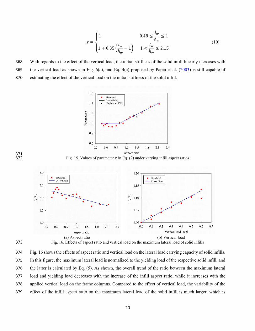
parameter z under the investigated infill aspect ratios in the present study, which is given by 367
20
𝑧𝑧 = ⎩⎨⎧1 0.48 ≤ 𝑙𝑙𝑤𝑤ℎ𝑤𝑤 ≤ 1
1 + 0.35 � 𝑙𝑙𝑤𝑤ℎ𝑤𝑤 − 1� 1 <𝑙𝑙𝑤𝑤ℎ𝑤𝑤 ≤ 2.15
(10)
With regards to the effect of the vertical load, the initial stiffness of the solid infill linearly increases with 368
the vertical load as shown in Fig. 6(a), and Eq. 4(a) proposed by Papia et al. (2003) is still capable of 369
estimating the effect of the vertical load on the initial stiffness of the solid infill. 370
371
Fig. 15. Values of parameter 𝑧𝑧 in Eq. (2) under varying infill aspect ratios 372
(a) Aspect ratio (b) Vertical load
Fig. 16. Effects of aspect ratio and vertical load on the maximum lateral load of solid infills 373
Fig. 16 shows the effects of aspect ratio and vertical load on the lateral load carrying capacity of solid infills. 374
In this figure, the maximum lateral load is normalized to the yielding load of the respective solid infill, and 375
the latter is calculated by Eq. (5). As shown, the overall trend of the ratio between the maximum lateral 376
load and yielding load decreases with the increase of the infill aspect ratio, while it increases with the 377
applied vertical load on the frame columns. Compared to the effect of vertical load, the variability of the 378
effect of the infill aspect ratio on the maximum lateral load of the solid infill is much larger, which is 379
21
consistent with the results shown in Figs. 3(b) and 6(b). The relationship between the maximum lateral load 380
and yielding load of the solid infill can be described by using a fitting formula with the consideration of the 381
effects of the infill aspect ratio and vertical load, which is expressed by 382
𝐹𝐹𝑚𝑚 = �2.45 − 0.36𝑙𝑙𝑤𝑤ℎ𝑤𝑤� (1 + 0.21𝜇𝜇)𝐹𝐹𝑦𝑦 (11)
where 𝜇𝜇 is the axial compression ratio. 383
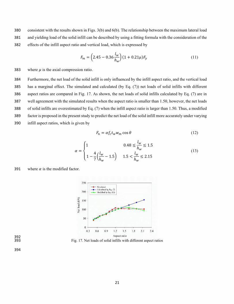
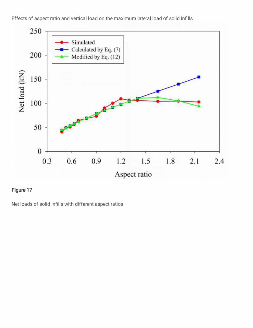
Furthermore, the net load of the solid infill is only influenced by the infill aspect ratio, and the vertical load 384
has a marginal effect. The simulated and calculated (by Eq. (7)) net loads of solid infills with different 385
aspect ratios are compared in Fig. 17. As shown, the net loads of solid infills calculated by Eq. (7) are in 386
well agreement with the simulated results when the aspect ratio is smaller than 1.50, however, the net loads 387
of solid infills are overestimated by Eq. (7) when the infill aspect ratio is larger than 1.50. Thus, a modified 388
factor is proposed in the present study to predict the net load of the solid infill more accurately under varying 389
infill aspect ratios, which is given by 390
𝐹𝐹𝑛𝑛 = 𝛼𝛼𝑓𝑓𝑐𝑐𝑡𝑡𝑤𝑤𝑤𝑤𝑚𝑚 cos 𝜃𝜃 (12)
𝛼𝛼 = ⎩⎨⎧1 0.48 ≤ 𝑙𝑙𝑤𝑤ℎ𝑤𝑤 ≤ 1.5
1 − 4
7� 𝑙𝑙𝑤𝑤ℎ𝑤𝑤 − 1.5� 1.5 <
𝑙𝑙𝑤𝑤ℎ𝑤𝑤 ≤ 2.15
(13)
where 𝛼𝛼 is the modified factor. 391
392
Fig. 17. Net loads of solid infills with different aspect ratios 393
394
22
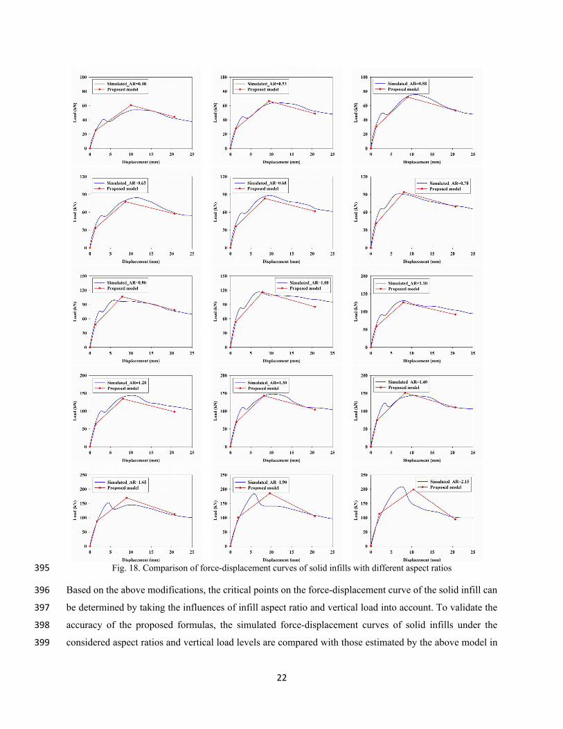
Fig. 18. Comparison of force-displacement curves of solid infills with different aspect ratios 395
Based on the above modifications, the critical points on the force-displacement curve of the solid infill can 396
be determined by taking the influences of infill aspect ratio and vertical load into account. To validate the 397
accuracy of the proposed formulas, the simulated force-displacement curves of solid infills under the 398
considered aspect ratios and vertical load levels are compared with those estimated by the above model in 399
23
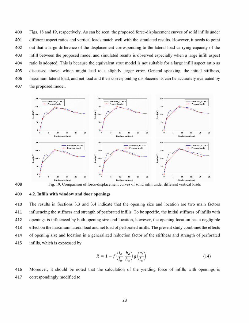
Figs. 18 and 19, respectively. As can be seen, the proposed force-displacement curves of solid infills under 400
different aspect ratios and vertical loads match well with the simulated results. However, it needs to point 401
out that a large difference of the displacement corresponding to the lateral load carrying capacity of the 402
infill between the proposed model and simulated results is observed especially when a large infill aspect 403
ratio is adopted. This is because the equivalent strut model is not suitable for a large infill aspect ratio as 404
discussed above, which might lead to a slightly larger error. General speaking, the initial stiffness, 405
maximum lateral load, and net load and their corresponding displacements can be accurately evaluated by 406
the proposed model. 407
Fig. 19. Comparison of force-displacement curves of solid infill under different vertical loads 408
4.2. Infills with window and door openings 409
The results in Sections 3.3 and 3.4 indicate that the opening size and location are two main factors 410
influencing the stiffness and strength of perforated infills. To be specific, the initial stiffness of infills with 411
openings is influenced by both opening size and location, however, the opening location has a negligible 412
effect on the maximum lateral load and net load of perforated infills. The present study combines the effects 413
of opening size and location in a generalized reduction factor of the stiffness and strength of perforated 414
infills, which is expressed by 415
𝑅𝑅 = 1 − 𝑓𝑓 �𝑙𝑙𝑜𝑜𝑙𝑙𝑤𝑤 ,ℎ𝑜𝑜ℎ𝑤𝑤� 𝑔𝑔 �𝑒𝑒𝑐𝑐𝑙𝑙𝑤𝑤� (14)
Moreover, it should be noted that the calculation of the yielding force of infills with openings is 416
correspondingly modified to 417
24
𝐹𝐹𝑦𝑦 = 𝑓𝑓𝑡𝑡𝑡𝑡𝑤𝑤(𝑙𝑙𝑤𝑤 − 𝑙𝑙𝑜𝑜) (15)
Through nonlinear regression analysis on the numerical results of infills with window openings, the 418
expressions of 𝑓𝑓 �𝑙𝑙𝑜𝑜𝑙𝑙𝑤𝑤 ,ℎ𝑜𝑜ℎ𝑤𝑤� and 𝑔𝑔 �𝑒𝑒𝑐𝑐𝑙𝑙𝑤𝑤� for the ratios of the stiffness and strength between the perforated and 419
solid infills are determined as follows. 420
For the initial stiffness of infills with window openings: 421
𝑓𝑓 �𝑙𝑙𝑜𝑜𝑙𝑙𝑤𝑤 ,ℎ𝑜𝑜ℎ𝑤𝑤� = 0.248
𝑙𝑙𝑜𝑜𝑙𝑙𝑤𝑤 + 0.266ℎ𝑜𝑜ℎ𝑤𝑤 + 1.202
𝑙𝑙𝑜𝑜𝑙𝑙𝑤𝑤 ℎ𝑜𝑜ℎ𝑤𝑤 (16a)
𝑔𝑔 �𝑒𝑒𝑐𝑐𝑙𝑙𝑤𝑤� = 1 + 0.664𝑒𝑒𝑐𝑐𝑙𝑙𝑤𝑤 (16b)
For the maximum lateral load (Eq. (17)) and net load (Eq. (18)) of infills with window openings: 422
𝑓𝑓 �𝑙𝑙𝑜𝑜𝑙𝑙𝑤𝑤 ,ℎ𝑜𝑜ℎ𝑤𝑤� = −1.180
𝑙𝑙𝑜𝑜𝑙𝑙𝑤𝑤 + 0.757ℎ𝑜𝑜ℎ𝑤𝑤 + 1.588
𝑙𝑙𝑜𝑜𝑙𝑙𝑤𝑤 ℎ𝑜𝑜ℎ𝑤𝑤 (17)
𝑓𝑓 �𝑙𝑙𝑜𝑜𝑙𝑙𝑤𝑤 ,ℎ𝑜𝑜ℎ𝑤𝑤� = 0.222
𝑙𝑙𝑜𝑜𝑙𝑙𝑤𝑤 + 0.290ℎ𝑜𝑜ℎ𝑤𝑤 + 0.915
𝑙𝑙𝑜𝑜𝑙𝑙𝑤𝑤 ℎ𝑜𝑜ℎ𝑤𝑤 (18)
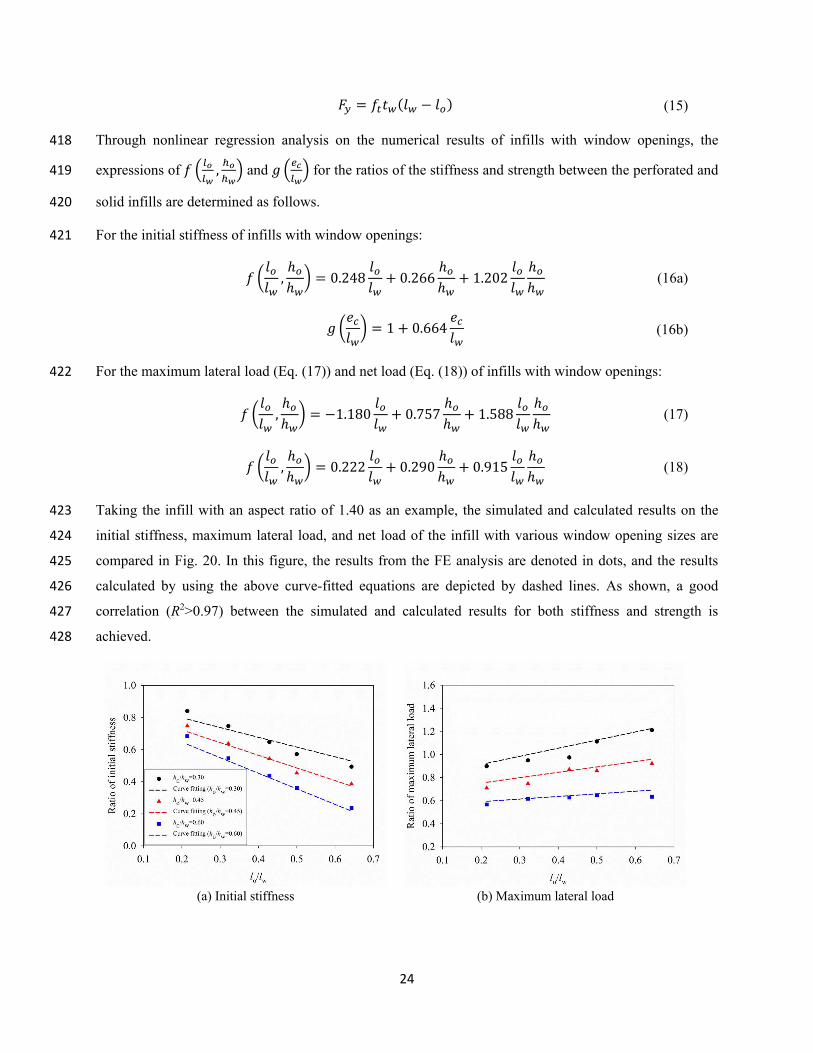
Taking the infill with an aspect ratio of 1.40 as an example, the simulated and calculated results on the 423
initial stiffness, maximum lateral load, and net load of the infill with various window opening sizes are 424
compared in Fig. 20. In this figure, the results from the FE analysis are denoted in dots, and the results 425
calculated by using the above curve-fitted equations are depicted by dashed lines. As shown, a good 426
correlation (R2>0.97) between the simulated and calculated results for both stiffness and strength is 427
achieved. 428
(a) Initial stiffness (b) Maximum lateral load
25
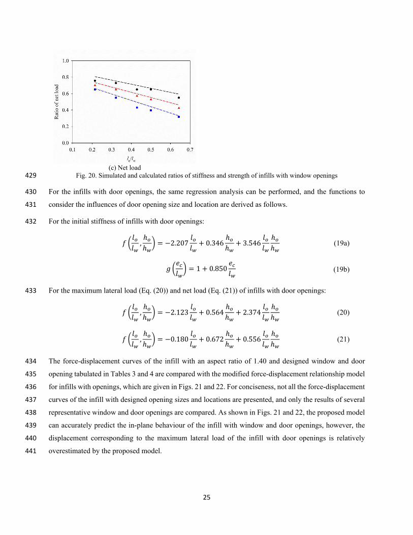
(c) Net load
Fig. 20. Simulated and calculated ratios of stiffness and strength of infills with window openings 429
For the infills with door openings, the same regression analysis can be performed, and the functions to 430
consider the influences of door opening size and location are derived as follows. 431
For the initial stiffness of infills with door openings: 432
𝑓𝑓 �𝑙𝑙𝑜𝑜𝑙𝑙𝑤𝑤 ,ℎ𝑜𝑜ℎ𝑤𝑤� = −2.207
𝑙𝑙𝑜𝑜𝑙𝑙𝑤𝑤 + 0.346ℎ𝑜𝑜ℎ𝑤𝑤 + 3.546
𝑙𝑙𝑜𝑜𝑙𝑙𝑤𝑤 ℎ𝑜𝑜ℎ𝑤𝑤 (19a)
𝑔𝑔 �𝑒𝑒𝑐𝑐𝑙𝑙𝑤𝑤� = 1 + 0.850𝑒𝑒𝑐𝑐𝑙𝑙𝑤𝑤 (19b)
For the maximum lateral load (Eq. (20)) and net load (Eq. (21)) of infills with door openings: 433
𝑓𝑓 �𝑙𝑙𝑜𝑜𝑙𝑙𝑤𝑤 ,ℎ𝑜𝑜ℎ𝑤𝑤� = −2.123
𝑙𝑙𝑜𝑜𝑙𝑙𝑤𝑤 + 0.564ℎ𝑜𝑜ℎ𝑤𝑤 + 2.374
𝑙𝑙𝑜𝑜𝑙𝑙𝑤𝑤 ℎ𝑜𝑜ℎ𝑤𝑤 (20)
𝑓𝑓 �𝑙𝑙𝑜𝑜𝑙𝑙𝑤𝑤 ,ℎ𝑜𝑜ℎ𝑤𝑤� = −0.180
𝑙𝑙𝑜𝑜𝑙𝑙𝑤𝑤 + 0.672ℎ𝑜𝑜ℎ𝑤𝑤 + 0.556
𝑙𝑙𝑜𝑜𝑙𝑙𝑤𝑤 ℎ𝑜𝑜ℎ𝑤𝑤 (21)
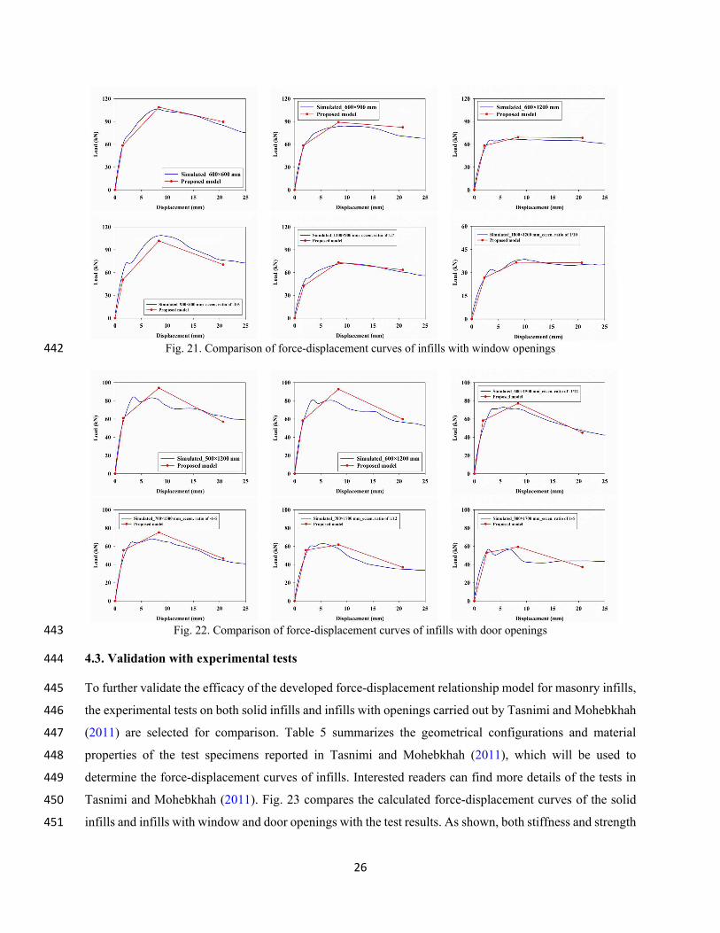
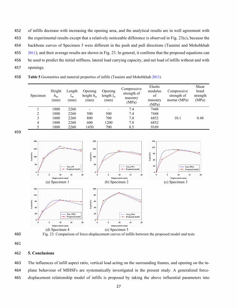
The force-displacement curves of the infill with an aspect ratio of 1.40 and designed window and door 434
opening tabulated in Tables 3 and 4 are compared with the modified force-displacement relationship model 435
for infills with openings, which are given in Figs. 21 and 22. For conciseness, not all the force-displacement 436
curves of the infill with designed opening sizes and locations are presented, and only the results of several 437
representative window and door openings are compared. As shown in Figs. 21 and 22, the proposed model 438
can accurately predict the in-plane behaviour of the infill with window and door openings, however, the 439
displacement corresponding to the maximum lateral load of the infill with door openings is relatively 440
overestimated by the proposed model. 441
26
Fig. 21. Comparison of force-displacement curves of infills with window openings 442
Fig. 22. Comparison of force-displacement curves of infills with door openings 443
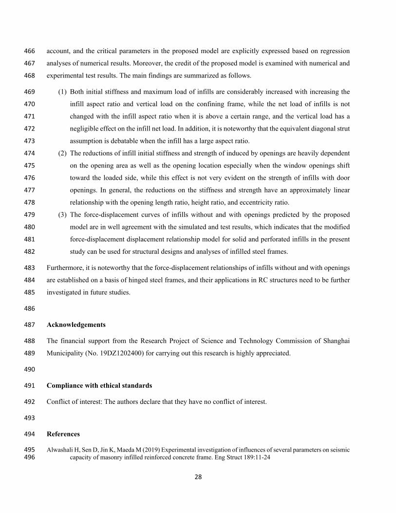
4.3. Validation with experimental tests 444
To further validate the efficacy of the developed force-displacement relationship model for masonry infills, 445
the experimental tests on both solid infills and infills with openings carried out by Tasnimi and Mohebkhah 446
(2011) are selected for comparison. Table 5 summarizes the geometrical configurations and material 447
properties of the test specimens reported in Tasnimi and Mohebkhah (2011), which will be used to 448
determine the force-displacement curves of infills. Interested readers can find more details of the tests in 449
Tasnimi and Mohebkhah (2011). Fig. 23 compares the calculated force-displacement curves of the solid 450
infills and infills with window and door openings with the test results. As shown, both stiffness and strength 451
27
of infills decrease with increasing the opening area, and the analytical results are in well agreement with 452
the experimental results except that a relatively noticeable difference is observed in Fig. 23(c), because the 453
backbone curves of Specimen 3 were different in the push and pull directions (Tasnimi and Mohebkhah 454
2011), and their average results are shown in Fig. 23. In general, it confirms that the proposed equations can 455
be used to predict the initial stiffness, lateral load carrying capacity, and net load of infills without and with 456
openings. 457
Table 5 Geometries and material properties of infills (Tasnimi and Mohebkhah 2011) 458
Specimen
Height ℎ𝑤𝑤
(mm)
Length 𝑙𝑙𝑤𝑤
(mm)
Opening
height ℎ𝑜𝑜
(mm)
Opening
length 𝑙𝑙𝑜𝑜
(mm)
Compressive
strength of
masonry
(MPa)
Elastic
modulus
of
masonry
(MPa)
Compressive
strength of
mortar (MPa)
Shear
bond
strength
(MPa)
1 1800 2260 - - 7.4 7448
10.1 0.48
2 1800 2260 500 500 7.4 7448
3 1800 2260 800 700 7.0 6852
4 1800 2260 600 1200 7.0 6852
5 1800 2260 1450 700 8.5 9169
459
(a) Specimen 1 (b) Specimen 2 (c) Specimen 3
(d) Specimen 4 (e) Specimen 5
Fig. 23. Comparison of force-displacement curves of infills between the proposed model and tests 460
461
5. Conclusions 462
The influences of infill aspect ratio, vertical load acting on the surrounding frames, and opening on the in-463
plane behaviour of MIHSFs are systematically investigated in the present study. A generalized force-464
displacement relationship model of infills is proposed by taking the above influential parameters into 465
28
account, and the critical parameters in the proposed model are explicitly expressed based on regression 466
analyses of numerical results. Moreover, the credit of the proposed model is examined with numerical and 467
experimental test results. The main findings are summarized as follows. 468
(1) Both initial stiffness and maximum load of infills are considerably increased with increasing the 469
infill aspect ratio and vertical load on the confining frame, while the net load of infills is not 470
changed with the infill aspect ratio when it is above a certain range, and the vertical load has a 471
negligible effect on the infill net load. In addition, it is noteworthy that the equivalent diagonal strut 472
assumption is debatable when the infill has a large aspect ratio. 473
(2) The reductions of infill initial stiffness and strength of induced by openings are heavily dependent 474
on the opening area as well as the opening location especially when the window openings shift 475
toward the loaded side, while this effect is not very evident on the strength of infills with door 476
openings. In general, the reductions on the stiffness and strength have an approximately linear 477
relationship with the opening length ratio, height ratio, and eccentricity ratio. 478
(3) The force-displacement curves of infills without and with openings predicted by the proposed 479
model are in well agreement with the simulated and test results, which indicates that the modified 480
force-displacement displacement relationship model for solid and perforated infills in the present 481
study can be used for structural designs and analyses of infilled steel frames. 482
Furthermore, it is noteworthy that the force-displacement relationships of infills without and with openings 483
are established on a basis of hinged steel frames, and their applications in RC structures need to be further 484
investigated in future studies. 485
486
Acknowledgements 487
The financial support from the Research Project of Science and Technology Commission of Shanghai 488
Municipality (No. 19DZ1202400) for carrying out this research is highly appreciated. 489
490
Compliance with ethical standards 491
Conflict of interest: The authors declare that they have no conflict of interest. 492
493
References 494
Alwashali H, Sen D, Jin K, Maeda M (2019) Experimental investigation of influences of several parameters on seismic 495
capacity of masonry infilled reinforced concrete frame. Eng Struct 189:11-24 496
29
Asteris PG, Antoniou S, Sophianopoulos DS, Chrysostomou CZ (2011) Mathematical macromodeling of infilled 497
frames: state of the art. J Struct Eng 137:1508-1517 498
Asteris PG, Cotsovos DM, Chrysostomou C, Mohebkhah A, Al-Chaar G (2013) Mathematical micromodeling of 499
infilled frames: state of the art. Eng Struct 56:1905-1921 500
Benavent-Climent A, Ramírez-Márquez A, Pujol S (2018) Seismic strengthening of low-rise reinforced concrete 501
frame structures with masonry infill walls: shaking-table test. Eng Struct 165:142-151 502
Campione G, Cavaleri L, Macaluso G, Amato G, Di Trapani F (2015) Evaluation of infilled frames: an updated in-503
plane-stiffness macro-model considering the effects of vertical loads. Bull Earthq Eng 13:2265-2281 504
Cavaleri L, Di Trapani F (2014) Cyclic response of masonry infilled RC frames: Experimental results and simplified 505
modeling. Soil Dyn Earthq Eng 65:224-242 506
Cavaleri L, Di Trapani F, Asteris PG, Sarhosis V (2017) Influence of column shear failure on pushover based 507
assessment of masonry infilled reinforced concrete framed structures: A case study. Soil Dyn Earthq Eng 508
100:98-112 509
Cavaleri L, Fossetti M, Papia M (2005) Infilled frames developments in the evaluation of cyclic behaviour under 510
lateral loads. Struct Eng Mech 21:469-494 511
Chen X, Liu Y (2015) Numerical study of in-plane behaviour and strength of concrete masonry infills with openings. 512
Eng Struct 82:226-235 513
Chen X, Liu Y (2016) A finite element study of the effect of vertical loading on the in-plane behavior of concrete 514
masonry infills bounded by steel frames. Eng Struct 117:118-129 515
Di Trapani F, Bolis V, Basone F, Preti M (2020) Seismic reliability and loss assessment of RC frame structures with 516
traditional and innovative masonry infills. Eng Struct 208:110306 517
Di Trapani F, Macaluso G, Cavaleri L, Papia M (2015) Masonry infills and RC frames interaction: literature overview 518
and state of the art of macromodeling approach. Eur J Environ Civil Eng 19:1059-1095 519
Dolšek M, Fajfar P (2008) The effect of masonry infills on the seismic response of a four-storey reinforced concrete 520
frame-a deterministic assessment. Eng Struct 30:1991-2001 521
El-Dakhakhni WW, Elgaaly M, Hamid AA (2003) Three-strut model for concrete masonry-infilled steel frames. J 522
Struct Eng 129:177-185 523
Gentile R, Pampanin S, Raffaele D, Uva G (2019) Non-linear analysis of RC masonry-infilled frames using the 524
SLaMA method: part 1-mechanical interpretation of the infill/frame interaction and formulation of the 525
procedure. Bull Earthq Eng 17:3283-3304 526
Gu X, Wang L, Zhang W, Cui W (2018) Cyclic behaviour of hinged steel frames enhanced by masonry columns 527
and/or infill walls with/without CFRP. Struct Infrastruct Eng 14:1470-1485 528
Humayun Basha S, Surendran S, Kaushik HB (2020) Empirical models for lateral stiffness and strength of masonry-529
infilled rc frames considering the influence of Openings. J Struct Eng 146:04020021 530
Kakaletsis D, Karayannis C (2008) Influence of masonry strength and openings on infilled R/C frames under cycling 531
loading. J Earthq Eng 12:197-221 532
Klingner RE, Bertero V (1978) Earthquake resistance of infilled frames. J Struct Div 104:973–989 533
Li C, Hao H, Bi K (2019) Seismic performance of precast concrete-filled circular tube segmental column under biaxial 534
lateral cyclic loadings. Bull Earthq Eng 17:271-296 535
Liauw T-C, Kwan K-H (1984) Nonlinear behaviour of non-integral infilled frames. Comput Struct 18:551-560 536
Liu Y, Manesh P (2013) Concrete masonry infilled steel frames subjected to combined in-plane lateral and axial 537
loading-An experimental study. Eng Struct 52:331-339 538
Mainstone RJ (1971) On the stiffness and strengths of infilled frame. Proc Inst Civil Eng Supplement IV:57-90 539
Markulak D, Radić I, Sigmund V (2013) Cyclic testing of single bay steel frames with various types of masonry infill. 540
Eng Struct 51:267-277 541
Mohammadi M, Emami SMM (2019) Multi-bay and pinned connection steel infilled frames: an experimental and 542
numerical study. Eng Struct 188:43-59 543
Mohammadi M, Nikfar F (2013) Strength and stiffness of masonry-infilled frames with central openings based on 544
experimental results. J Struct Eng 139:974-984 545
Ministry of Housing and Urban-Rural Development of the People’s Republic of China (MOHURD) (2010) Code for 546
design of concrete structures-GB50010. Architecture and Building Press, Beijing (in Chinese) 547
Ministry of Housing and Urban-Rural Development of the People’s Republic of China (MOHURD) (2011) Code for 548
design of masonry structures-GB50003. Architecture and Building Press, Beijing (in Chinese) 549
Ministry of Housing and Urban-Rural Development of the People’s Republic of China (MOHURD) (2017) Code for 550
design of steel structures-GB50017. Architecture and Building Press, Beijing (in Chinese) 551
30
Morandi P, Hak S, Magenes G (2018) Performance-based interpretation of in-plane cyclic tests on RC frames with 552
strong masonry infills. Eng Struct 156:503-521 553
Papia M, Cavaleri L, Fossetti M (2003) Infilled frames developments in the evaluation of the stiffening effect of infills. 554
Struct Eng Mech 16:675-693 555
Perrone D, Leone M, Aiello MA (2017) Non-linear behaviour of masonry infilled RC frames: Influence of masonry 556
mechanical properties. Eng Struct 150:875-891 557
Polyakov S (1960) On the interaction between masonry filler walls and enclosing frame when loaded in the plane of 558
the wall. Translation in Earthquake Engineering. Earthquake Engineering Research Institute (EERI), San 559
Francisco, California, pp 36-42 560
Shing PB, Mehrabi AB (2002) Behaviour and analysis of masonry-infilled frames. Prog Struct Eng Mater 4:320-331 561
Tasnimi A, Mohebkhah A (2011) Investigation on the behavior of brick-infilled steel frames with openings, 562
experimental and analytical approaches. Eng Struct 33:968-980 563
Uva G, Porco F, Fiore A (2012a) Appraisal of masonry infill walls effect in the seismic response of RC framed 564
buildings: A case study. Eng Struct 34:514-526 565
Uva G, Raffaele D, Porco F, Fiore A (2012b) On the role of equivalent strut models in the seismic assessment of 566
infilled RC buildings. Eng Struct 42:83-94 567
Zuo H, Zhang W, Wang B, Gu X (2021) Seismic behaviour of masonry infilled hinged steel frames with openings: 568
Experimental and numerical studies. Bull Earthq Eng 19:1311-1335 569
Figures
Figure 1
FE model of MIHSFs
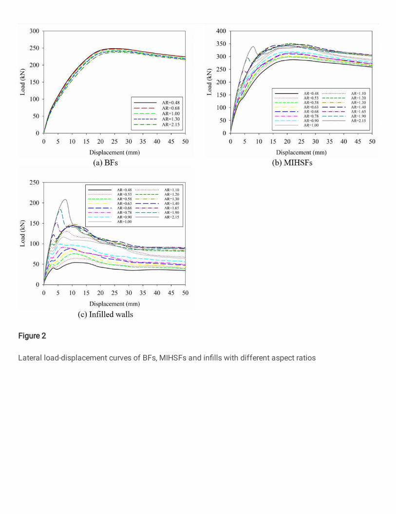
Figure 2
Lateral load-displacement curves of BFs, MIHSFs and in�lls with different aspect ratios
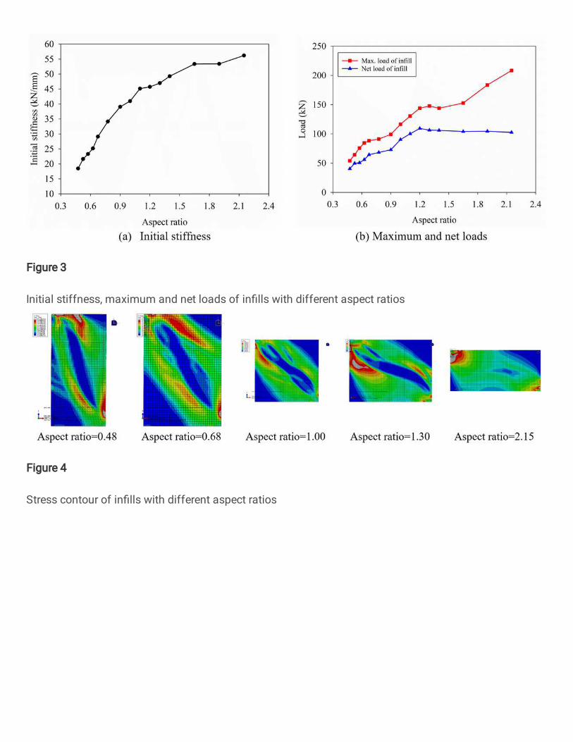
Figure 3
Initial stiffness, maximum and net loads of in�lls with different aspect ratios
Figure 4
Stress contour of in�lls with different aspect ratios
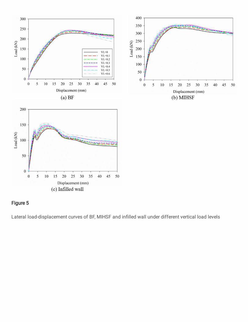
Figure 5
Lateral load-displacement curves of BF, MIHSF and in�lled wall under different vertical load levels
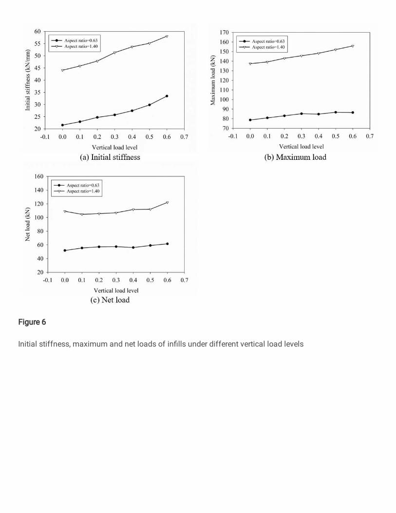
Figure 6
Initial stiffness, maximum and net loads of in�lls under different vertical load levels
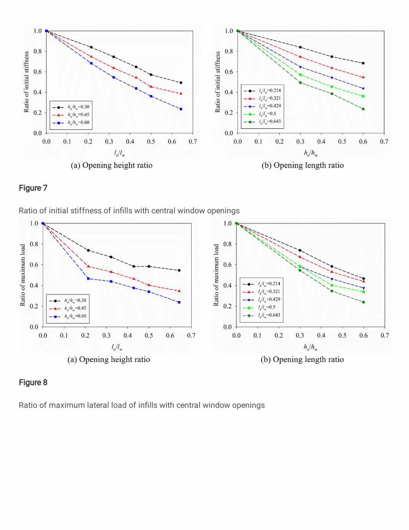
Figure 7
Ratio of initial stiffness of in�lls with central window openings
Figure 8
Ratio of maximum lateral load of in�lls with central window openings
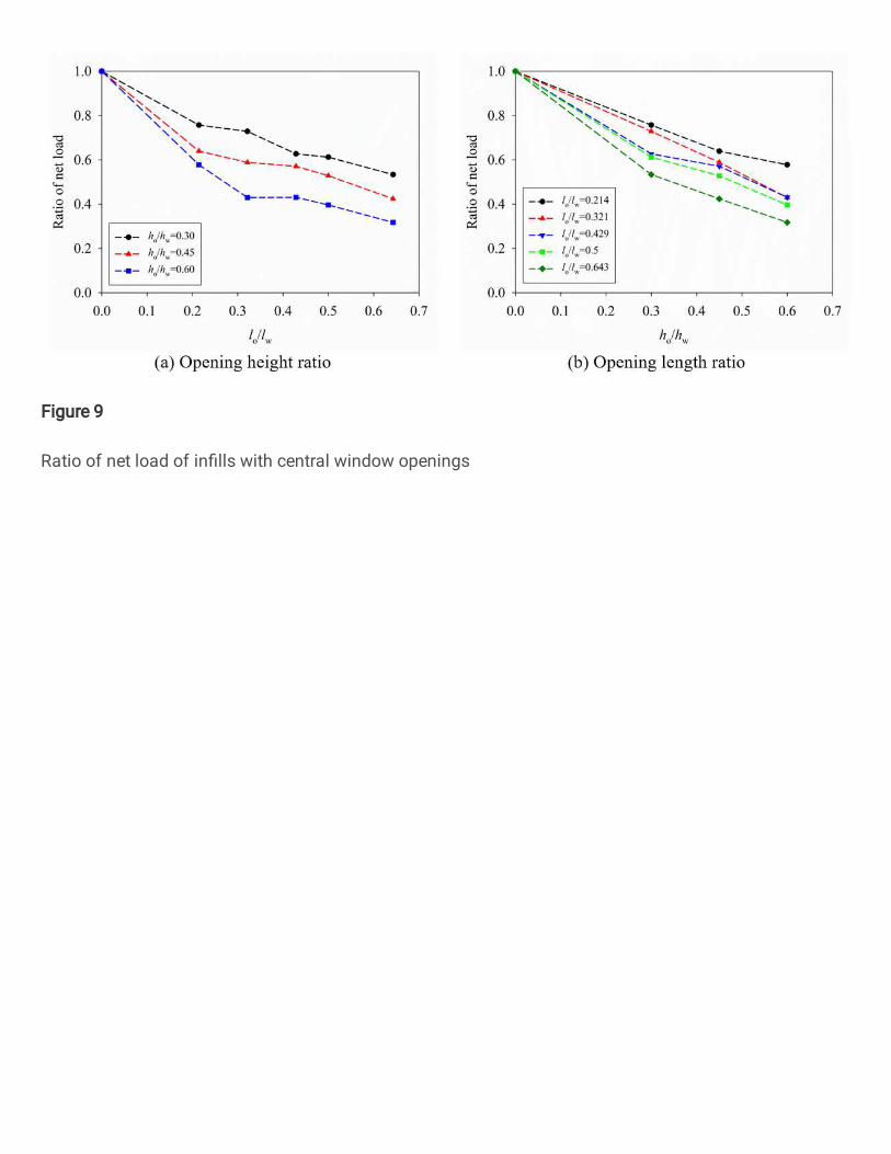
Figure 9
Ratio of net load of in�lls with central window openings
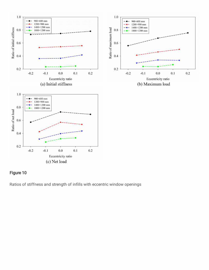
Figure 10
Ratios of stiffness and strength of in�lls with eccentric window openings
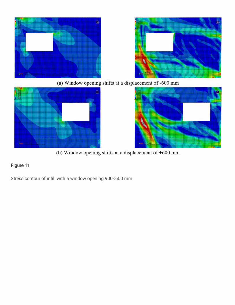
Figure 11
Stress contour of in�ll with a window opening 900×600 mm
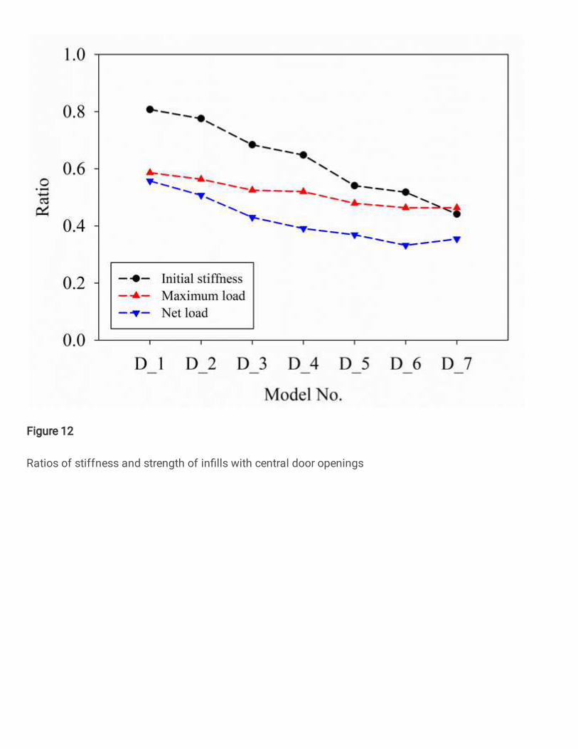
Figure 12
Ratios of stiffness and strength of in�lls with central door openings
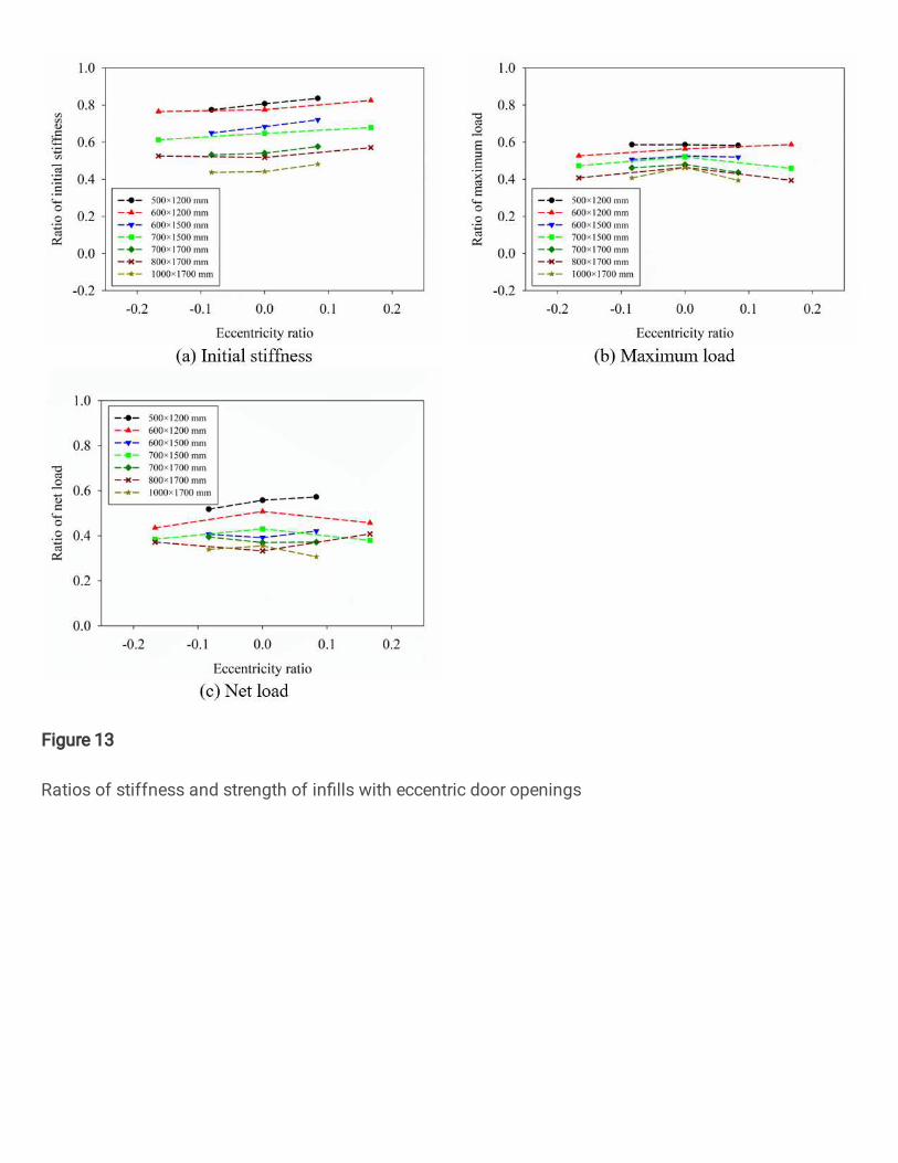
Figure 13
Ratios of stiffness and strength of in�lls with eccentric door openings
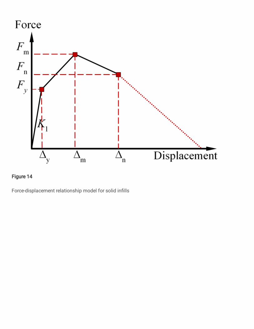
Figure 14
Force-displacement relationship model for solid in�lls
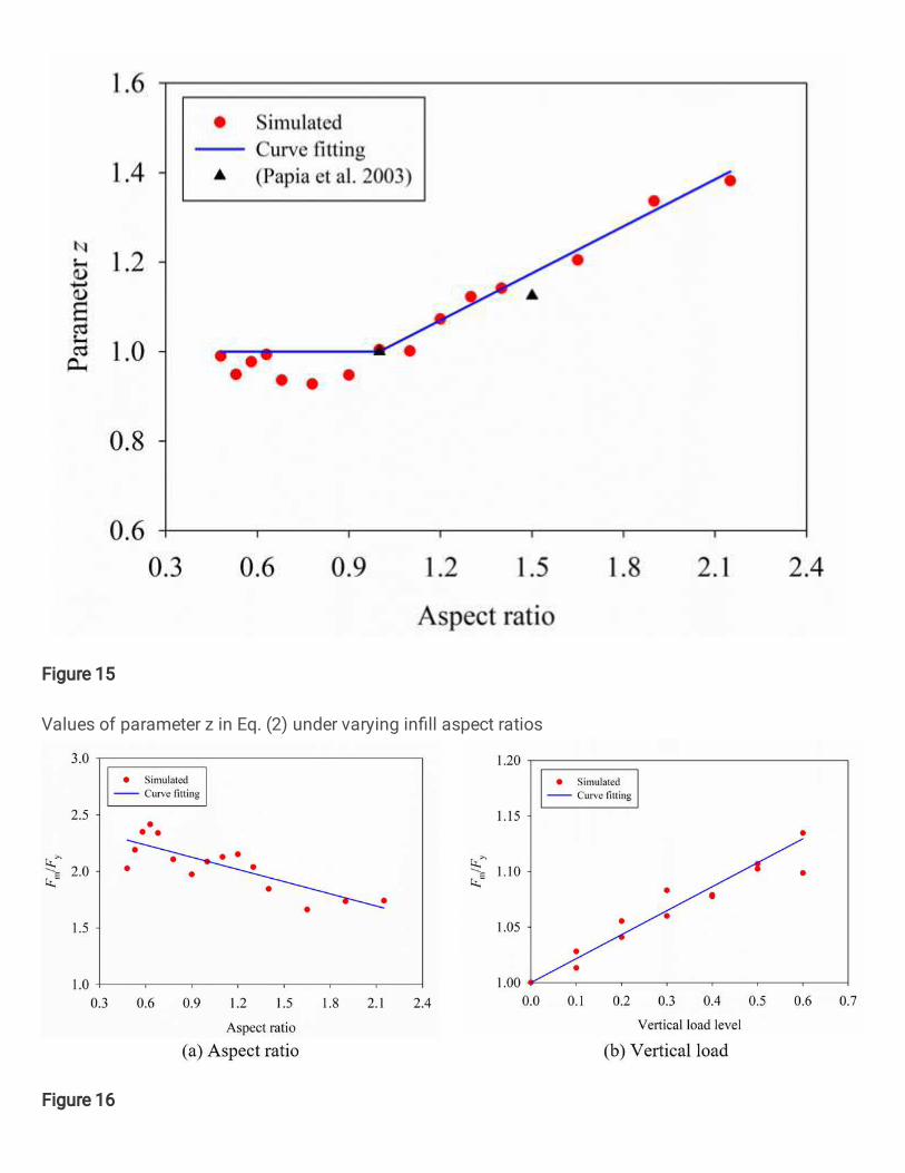
Figure 15
Values of parameter z in Eq. (2) under varying in�ll aspect ratios
Figure 16
Effects of aspect ratio and vertical load on the maximum lateral load of solid in�lls
Figure 17
Net loads of solid in�lls with different aspect ratios
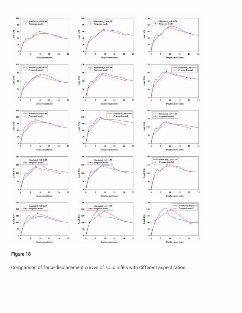
Figure 18
Comparison of force-displacement curves of solid in�lls with different aspect ratios
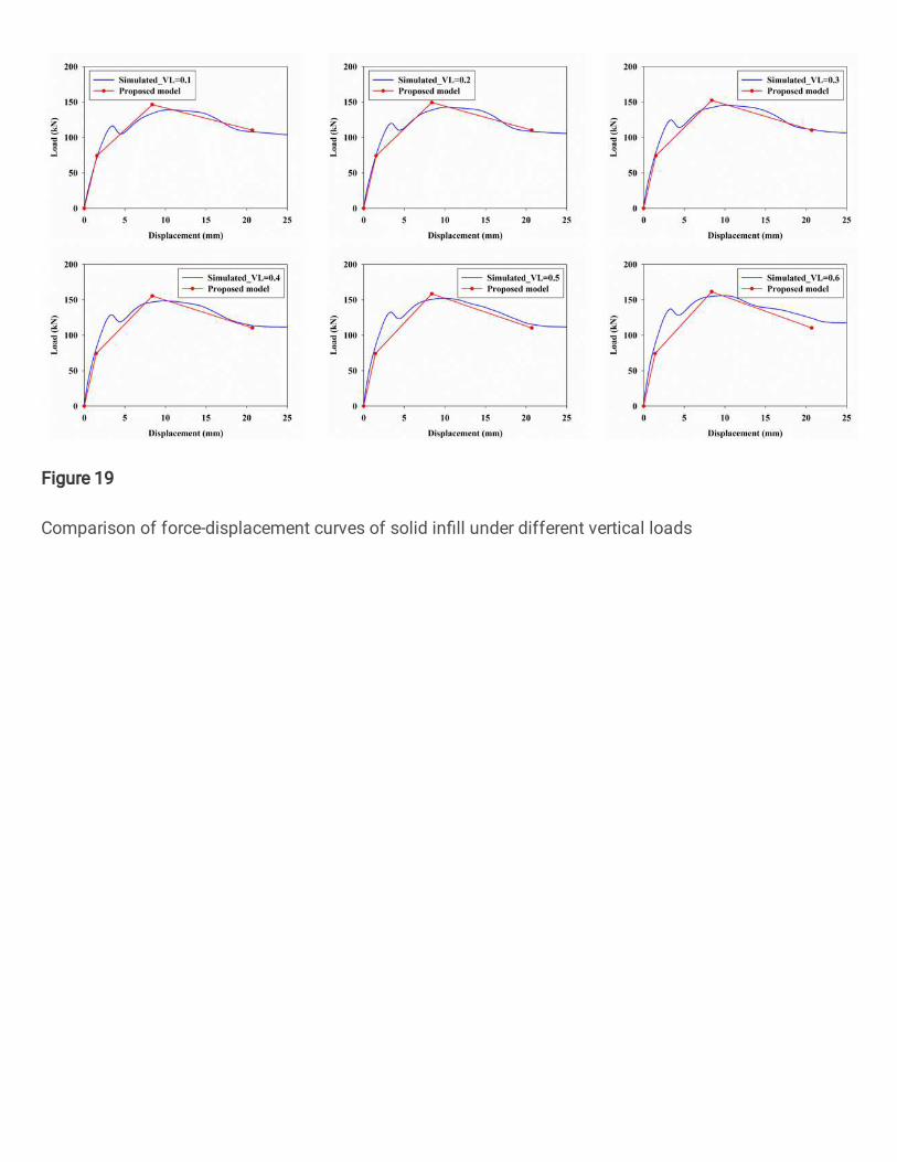
Figure 19
Comparison of force-displacement curves of solid in�ll under different vertical loads
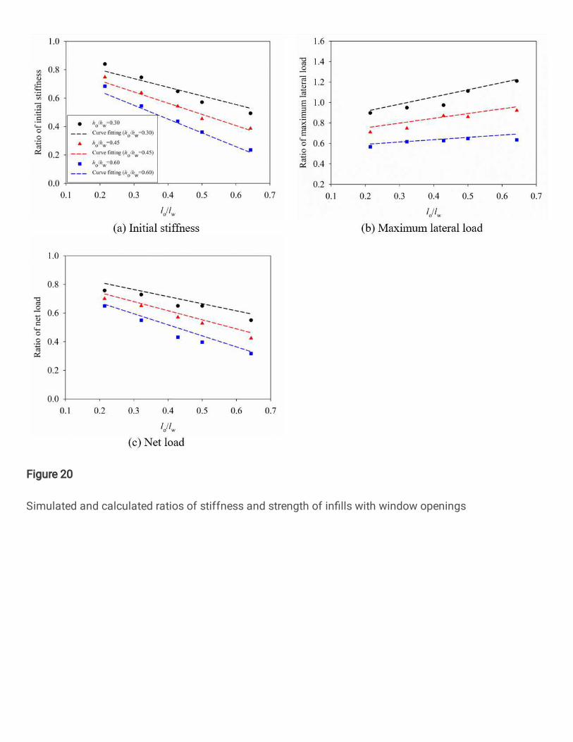
Figure 20
Simulated and calculated ratios of stiffness and strength of in�lls with window openings
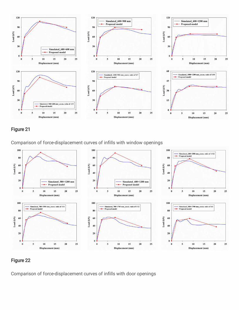
Figure 21
Comparison of force-displacement curves of in�lls with window openings
Figure 22
Comparison of force-displacement curves of in�lls with door openings
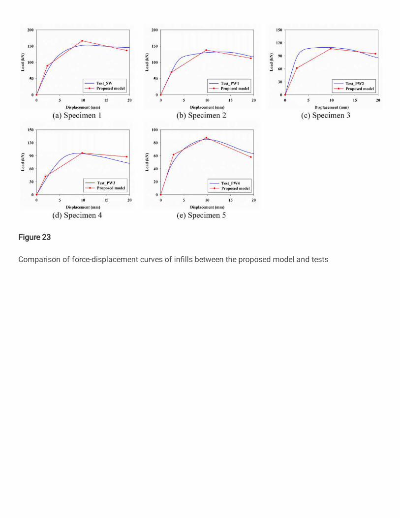
Figure 23
Comparison of force-displacement curves of in�lls between the proposed model and tests