Embed Size (px)
Citation preview

Forest residues: Harvesting, storage and fuel value
Seamus HoyneAdrian Thomas
ii
ACKNOWLEDGEMENTS
The editors of this publication would like to acknowledge the following for their contribution to the workcarried out during this study:
University of Limerick, Dept. of Mechanical and Aeronautical Engineering• Prof Patrick Mallon, previous Head of Department, for assistance and support.• Mr Patrick O’Donnell and all the staff in the workshop for their dedicated work in construction of the
bundler.• The administration staff of the Department for assistance on the project.• Final Year Project Students in the Department who completed specific tasks during the project.
Timberline Ltd• Mr Dave and Richard Brickenden who supplied and operated the forwarder which was used to complete the
test trails of the bundler. Their contribution and knowledge was vital to the success of the project.
Teva Ltd, Galway• Mr John Joe Healy and the staff of TEVA Ltd for their assistance in production of parts of the machine and
technical advice.
Keltec Ltd, Limerick• For completion of final assembly of bundler.
Finsa Forest Products Ltd, Clare• Mr Liam McElligot and Mr Robert Percy who stored and used the bundled material as a fuel.
EnviroGrind Ltd• Mr Martin Eaves whose equipment was used to grind the bundled material at the Finsa Forest Products site.
Coillte• Mr Pat Hanrahan, Coillte Office, Limerick and Mr Dan Dinneen, Coillte Office, Doon for their assistance in
selection of trial sites and overall contribution to the project.
COFORD (National Council for Forest Research and Development) • For funding the research and publication of the results.
All of the other individuals and organisations who contributed in some way to the success of the project.
iii
TABLE OF CONTENTS
FOREWORD v
1. SETTING THE SCENE: ENERGY IN IRELAND AND WOOD AS A RENEWABLE ENERGY 1
2. THE FOREST RESIDUE RESOURCE 2
3. OBJECTIVES 2
4. BACKGROUND TO THE PROJECT 34.1 WOOD HARVESTING IN GENERAL 34.2 FOREST RESIDUES - TECHNICAL AND ECONOMIC BARRIERS TO THEIR USE FOR ENERGY GENERATION 34.3 ECONOMICS OF HARVESTING AND HANDLING RESIDUES 34.3.1 Chipping 44.3.2 Bundling 4
5. POTENTIAL USE OF BUNDLING, DEVELOPMENT OF DESIGN SPECIFICATION 55.1 POTENTIAL USE OF BUNDLING 55.2 DEVELOPMENT OF THE DESIGN SPECIFICATION FOR BUNDLING 55.2.1 Establishing compaction forces 7
6. MACHINE DESIGN, BUILD AND OPERATION 86.1 DESIGN 86.1.1 Location of the bundler and mounting on forwarder 86.1.2 Orientation on forwarder 86.1.3 Compaction ratios 86.1.4 Hydraulic System 96.1.5 End trimming 106.1.6 Strapping 106.2 MACHINE BUILD 106.3 MACHINE OPERATION 106.3.1 Bundle manufacture 106.3.2 Varying bundle size and compaction ratio 116.3.3 Bundling trials 116.3.3.1 Site 1 - Commissioning 116.3.3.2 Site 2 - First trial site 116.3.3.3 Site 3 - Second trial site, Buffanoka 12
7. HANDLING, HAULAGE, STORAGE AND ANALYSIS OF BUNDLE 137.1 HANDLING AND HAULAGE 137.2 DETERMINATION OF BUNDLE WEIGHT 137.3 TRIMMING 147.4 STORAGE 147.4.1 Storage Period 1 (August 1996 - December 1996) 147.4.2 Storage Period 2 (December 1996 - April 1997) 157.5 ANALYSIS OF BUNDLE/RESIDUE MATERIAL PROPERTIES 15
8. RESULTS 168.1 BUNDLE WEIGHT CHANGE DURING STORAGE, TRIMMING AND STACKING 168.1.1 Storage 168.1.2 Trimming 168.1.3 Stacking 168.2 BUNDLE AND BUNDLE STACK STABILITY 168.3 BUNDLE/RESIDUE MATERIAL PROPERTIES 168.4 BUNDLE MOISTURE CONTENT 168.5 CALORIFIC VALUE 16

iv
9. DISCUSSION 179.1 MACHINE OPERATION 179.2 PRODUCTION OF BUNDLES AND PERFORMANCE OF BUNDLER ON DIFFERENT SITES 189.3 BUNDLE MANUFACTURE 189.4 TRIMMING OF BUNDLES 199.5 NEEDLE LOSS FROM BUNDLES 199.6 HANDLING AND HAULAGE OF BUNDLES 209.7 BUNDLE DRYING 209.7.1 Weight loss over time 209.7.2 Drying and bundle orientation 219.8 RESIDUE SIZE DISTRIBUTION AND ITS EFFECT ON CONVERSION 229.9 BUNDLE APPEARANCE, FUNGAL GROWTH AND SELF-HEATING 229.10 CALORIFIC VALUE OF THE BUNDLED RESIDUES 22
10. CONCLUSIONS 25
REFERENCES 26

v
FOREWORD
A feature of COFORD's research programme has been the recognition that an enormous potential exists inIreland for the development of alternative, renewable, wood-based energy systems. Wood energy generationhas distinct advantages over other conventional fuels, especially in the light of Ireland's commitment toreducing its CO2 emissions under the Kyoto Protocol. Furthermore, the growing Irish forest industry is well-suited to the development of a wood fuel industry, specifically tailored to Irish conditions.
This work that is reported was highly innovative. It sought to develop a method for the harvesting of forestresidues left on the forest floor following harvesting. A number of systems were reviewed in countries such asFinland and Sweden, where forest residues are already used to a significant and growing extent as a fuel forcombined heat and power generation. The project involved work not just on residue collection - a prototypeforest residue bundler was designed for Irish conditions - but examined other important and practical issuessuch as the handling, drying and storage of residue bundles. In addition, valuable work was carried out onthe energy value of forest residues.
The work is valuable not only in the results obtained but in the general background it outlines as far as theuse of wood for energy is concerned. As we have indicated, wood energy has the potential to make asignificant contribution to achieving national targets for renewable energy and reduction of greenhouse gasemissions. There is a rapidly increasing area of private plantations in this country, many, if not most, ofwhich would benefit from early thinning. These thinnings are an ideal wood fuel source. Harvesting residues,as outlined in this report, are another potential source. Indeed a wood fuel assortment could be a feature ofall forest harvesting in the future.
David Nevins Eugene HendrickChairman DirectorCOFORD COFORD
May 2001
vi
1
1. SETTING THE SCENE: ENERGYIN IRELAND AND WOOD AS ARENEWABLE ENERGY
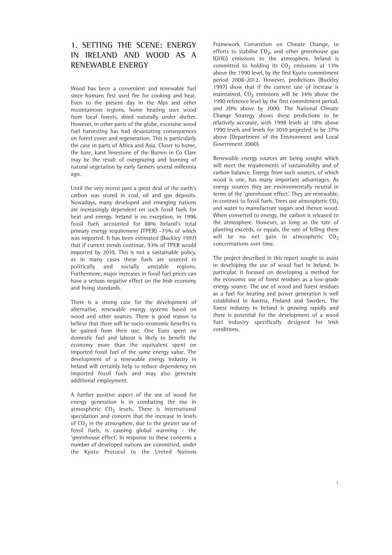
Wood has been a convenient and renewable fuelsince humans first used fire for cooking and heat.Even to the present day in the Alps and othermountainous regions, home heating uses woodfrom local forests, dried naturally under shelter.However, in other parts of the globe, excessive woodfuel harvesting has had devastating consequenceson forest cover and regeneration. This is particularlythe case in parts of Africa and Asia. Closer to home,the bare, karst limestone of the Burren in Co Claremay be the result of overgrazing and burning ofnatural vegetation by early farmers several millenniaago.
Until the very recent past a great deal of the earth’scarbon was stored in coal, oil and gas deposits.Nowadays, many developed and emerging nationsare increasingly dependent on such fossil fuels forheat and energy. Ireland is no exception, in 1996fossil fuels accounted for 88% Ireland’s totalprimary energy requirement (TPER) -75% of whichwas imported. It has been estimated (Buckley 1997)that if current trends continue, 93% of TPER wouldimported by 2010. This is not a sustainable policy,as in many cases these fuels are sourced inpolitically and socially unstable regions.Furthermore, major increases in fossil fuel prices canhave a serious negative effect on the Irish economyand living standards.
There is a strong case for the development ofalternative, renewable energy systems based onwood and other sources. There is good reason tobelieve that there will be socio-economic benefits tobe gained from their use. One Euro spent ondomestic fuel and labour is likely to benefit theeconomy more than the equivalent spent onimported fossil fuel of the same energy value. Thedevelopment of a renewable energy industry inIreland will certainly help to reduce dependency onimported fossil fuels and may also generateadditional employment.
A further positive aspect of the use of wood forenergy generation is in combating the rise inatmospheric CO2 levels. There is internationalspeculation and concern that the increase in levelsof CO2 in the atmosphere, due to the greater use offossil fuels, is causing global warming - the‘greenhouse effect’. In response to these concerns anumber of developed nations are committed, underthe Kyoto Protocol to the United Nations
Framework Convention on Climate Change, toefforts to stabilise CO2, and other greenhouse gas(GHG) emissions to the atmosphere. Ireland iscommitted to holding its CO2 emissions at 13%above the 1990 level, by the first Kyoto commitmentperiod 2008-2012. However, predictions (Buckley1997) show that if the current rate of increase ismaintained, CO2 emissions will be 34% above the1990 reference level by the first commitment period,and 20% above by 2000. The National ClimateChange Strategy shows these predictions to berelatively accurate, with 1998 levels at 18% above1990 levels and levels for 2010 projected to be 37%above (Department of the Environment and LocalGovernment 2000).
Renewable energy sources are being sought whichwill meet the requirements of sustainability and ofcarbon balance. Energy from such sources, of whichwood is one, has many important advantages. Asenergy sources they are environmentally neutral interms of the ‘greenhouse effect’. They are renewable,in contrast to fossil fuels. Trees use atmospheric CO2and water to manufacture sugars and thence wood.When converted to energy, the carbon is released tothe atmosphere. However, as long as the rate ofplanting exceeds, or equals, the rate of felling therewill be no net gain in atmospheric CO2concentrations over time.
The project described in this report sought to assistin developing the use of wood fuel in Ireland. Inparticular, it focused on developing a method forthe economic use of forest residues as a low-gradeenergy source. The use of wood and forest residuesas a fuel for heating and power generation is wellestablished in Austria, Finland and Sweden. Theforest industry in Ireland is growing rapidly andthere is potential for the development of a woodfuel industry specifically designed for Irishconditions.
2
2. THE FOREST RESIDUE RESOURCE
In Ireland, forest residues are usually left on theforest floor after wood harvest. Occasionally someof the larger waste wood is removed as firewood fordomestic consumption but this does not occur onany scale. It has been estimated that the amount offorest residues varies from 50 to 100 odt/ha (ovendry tonnes) depending on species, age, site type andwood assortments harvested (Mitchell and Hankin1993). The total annual residue resource that iscurrently available has been estimated as between300-400,000 t (Bulfin and Rice 1995). About halfof this may be available for harvest. In energy(electricity) terms a study on the total renewableenergy resource in Ireland (ESBI 1997) estimatedthat residues could contribute 26 MW in 2000 and145 MW by 2020 (at a cut-off price of 5.5p/kWh).
A significant factor in assessing the residue resourceis the size of the material (harvesting is normally toa top diameter of 70 mm) and the amount of deadand waste wood which is left on the site afterextraction. Some of the material in the presentstudy was up to 125 mm in diameter and over 4 min length. On some sites in Co Limerick and Clare, itwas estimated that up to 40% d.m. (dry matter) ofharvestable residues was over 25 mm diameter.
3. OBJECTIVES
The project set out to explore the potential for thedevelopment of forest residues as a fuel source inIreland. The first part of the project involved aliterature review, which identified the key issues inthe wood fuel supply chain. Based on the findingsof the review it was decided to investigate thetechnical feasibility of bundling forest residues.
Specifically the objectives of the second part of theproject were to:
1. develop and test a mobile bundling machine;2. analyse the effects of bundle size and density;3. study the behaviour of forest residues when
bundled and left to dry naturally;4. analyse the optimum drying period, time of year
of production and drying position;5. analyse variation in moisture content, calorific
value and dry matter losses in bundles;6. utilise the results in the design of a mobile forest
residue bundling machine.
This report covers the second part of the project.Copies of the literature review are available onrequest from COFORD.
3
4. BACKGROUND TO THE PROJECT
4.1 WOOD HARVESTING IN GENERAL
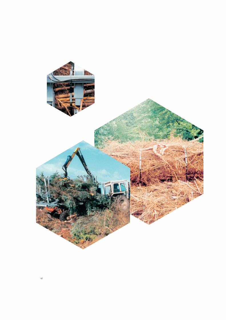
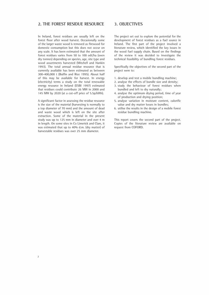
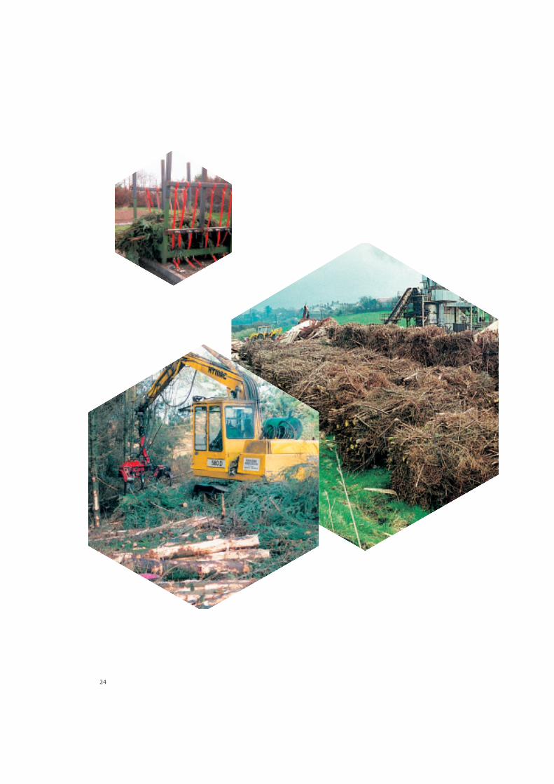
Tree felling and delimbing in Ireland has becomeincreasingly mechanised. Harvesting heads are fittedto purpose-built machines or on excavatorsconverted for harvesting (Figure 1). These are ableto produce lengths of delimbed wood to reasonablyconsistent dimensions.
More advanced harvesting heads are able to recordproduction by measuring diameters and lengths,and number of pieces processed. While delimbing,the normal practice is for the harvester to place theresidues (tops and branches) in front of the machineto form a brash mat, while cut-to-length wood isplaced on either side of the mat (Figure 2).Forwarders extracting wood travel on the brash mat,which provides better traction while at the sametime protecting the soil.
Other systems involve the extraction of the wholetree to a roadside tree processor which delimbs,debarks, chips and cuts to length at one location.Whole trees can be brought to the roadside byforwarder but this process may be more expensivethan cable extraction systems which are sometimesused. Cable extraction is more suitable for steepslopes, or on soft terrain with access difficulties.
4.2 FOREST RESIDUES - TECHNICAL AND ECONOMIC
BARRIERS TO THEIR USE FOR ENERGY GENERATION
A review was undertaken by Hoyne (1996) of thewood fuel industry with a view to identifyingbarriers to, and opportunities for, development ofwood energy. The review identified the growth inthe use of forest residues as a fuel source in Finlandand Sweden where considerable work had beendone with wood chips. They were, and remain, themost common form in which wood fuel is used forcombustion and gasification.
Hoyne (op. cit.) identified a number of problemswhich contributed to the relatively high cost offorest residues as a feed-stock for power generation.In particular, their bulky nature, and handlingdifficulties, either loose or as chips, were drawbacks.He concluded that under Irish conditions forestresidues had difficulty in being accepted as analternative energy source against a background ofhistorically low oil prices and the concern over theremoval of nutrients from poor soils.
4.3 ECONOMICS OF HARVESTING AND HANDLING
RESIDUES
Forwarder extraction of unsorted, uncompactedforest residues is usually uneconomic as the bulkynature of the material results in low payloads.
Figure 1: Hymac excavator fitted with a harvesting head placing wood lengths alongside residues whichform a brash mat under the tracked vehicle.
4
A typical 8 t forwarder would only extract 2-3 t ofresidues in the uncompacted state (Brunberg 1995).Therefore more productive systems are needed.
4.3.1 ChippingThe low bulk density of loose residue material (150kg/m3) (Larsson and Norden 1982) results in averagelorry loads of 15 t, only half the legal load limit.Haulage is therefore a major factor in the overallcost of delivered wood fuel. While wood chips areless bulky (220 - 265 kg/m3) they can be difficult tostore unless dry. Self-combustion and fungal growthleading to operator health problems (such asfarmer’s lung) are the main hazards. In addition tothe these drawbacks chipping has two otherdisadvantages:
1. chips are bulky and require specialised machineryto produce and transport;2. in many cases, residues are contaminated by soiland stones which can cause damage to the chipper.
Chipping systems have been developed mainly inFinland and Sweden. One currently popular systemis terrain chipping. A machine similar to a forwarder,with a mounted tipping tank for storing chipsmoves through the site. A crane is used to feedresidues into the chipper from where chips areblown into a storage tank. When the tank is full ashuttle vehicle comes alongside and brings the chipsto a roadside stockpile. In some situations thechipper also brings the chips to roadside.
The start-up costs for a chipping unit would includepurchase of a chipper, conversion of at least one
forwarder to shuttle duties, a loading shovel, truckswith high sides (adapted for forest roads) andsuitable storage areas either in the forest or at adepot. In the event of a rise in the price of oil thecost of operating chippers will rise in tandem. Notalone will the fuel cost per tonne harvested rise, butthe capital cost of specialised machinery may alsorise.
4.3.2 BundlingHoyne (1996) examined the use of harvesting andhandling systems other than chipping, that have thepotential to improve the cost competitiveness ofresidues as an energy source. In particular, heinvestigated the use of bundling in Sweden andconcluded that it had potential as a system toharvest and handle residues. The key drivers behindthe bundling concept are:- to increase the bulk density of the material being
transported and hence a reduction in transport costs;
- compact, uniform bundles are easier to handleand store than loose residues;
- material stored in bundles appears to drysufficiently to improve its fuel quality;
- the requirement for new machinery is minimisedas existing forestry equipment can be utilised forhandling and transport.
Although the systems under development in Swedenand other countries have merit, it was concludedthat it would not be possible to simply replicatesuch systems in Ireland. There was a need, therefore,to develop a system which was applicable underIrish conditions.
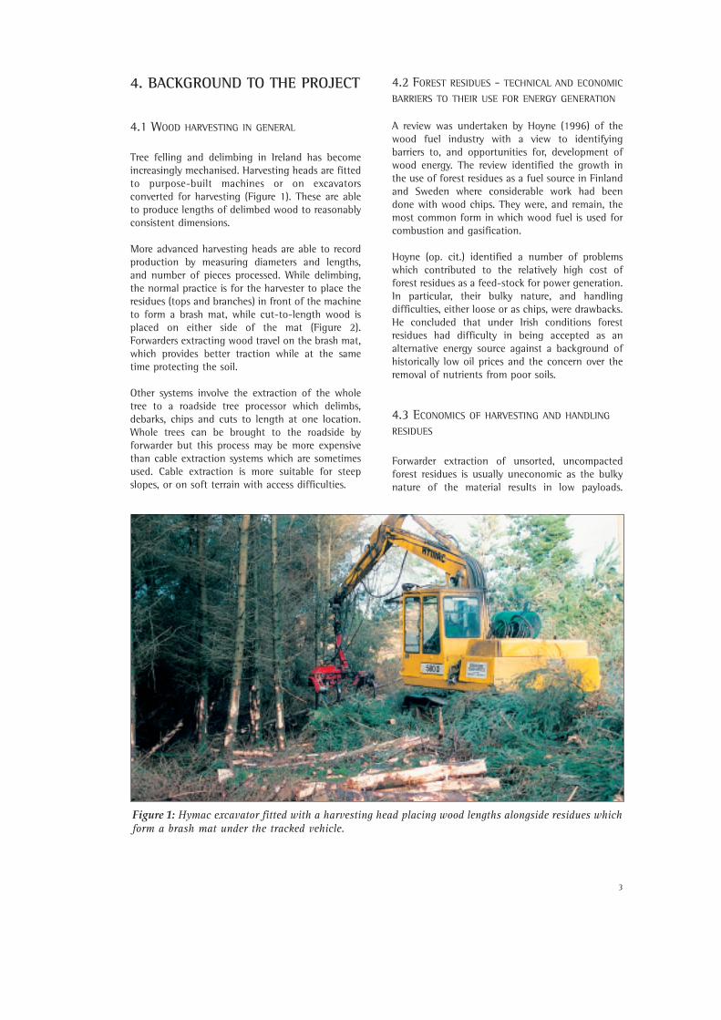
Figure 2: Brash mat of fresh forest residues at Murroe, Co Limerick.
5
5. POTENTIAL USE OF BUNDLING, DEVELOPMENT OF DESIGNSPECIFICATION
5.1 POTENTIAL USE OF BUNDLING
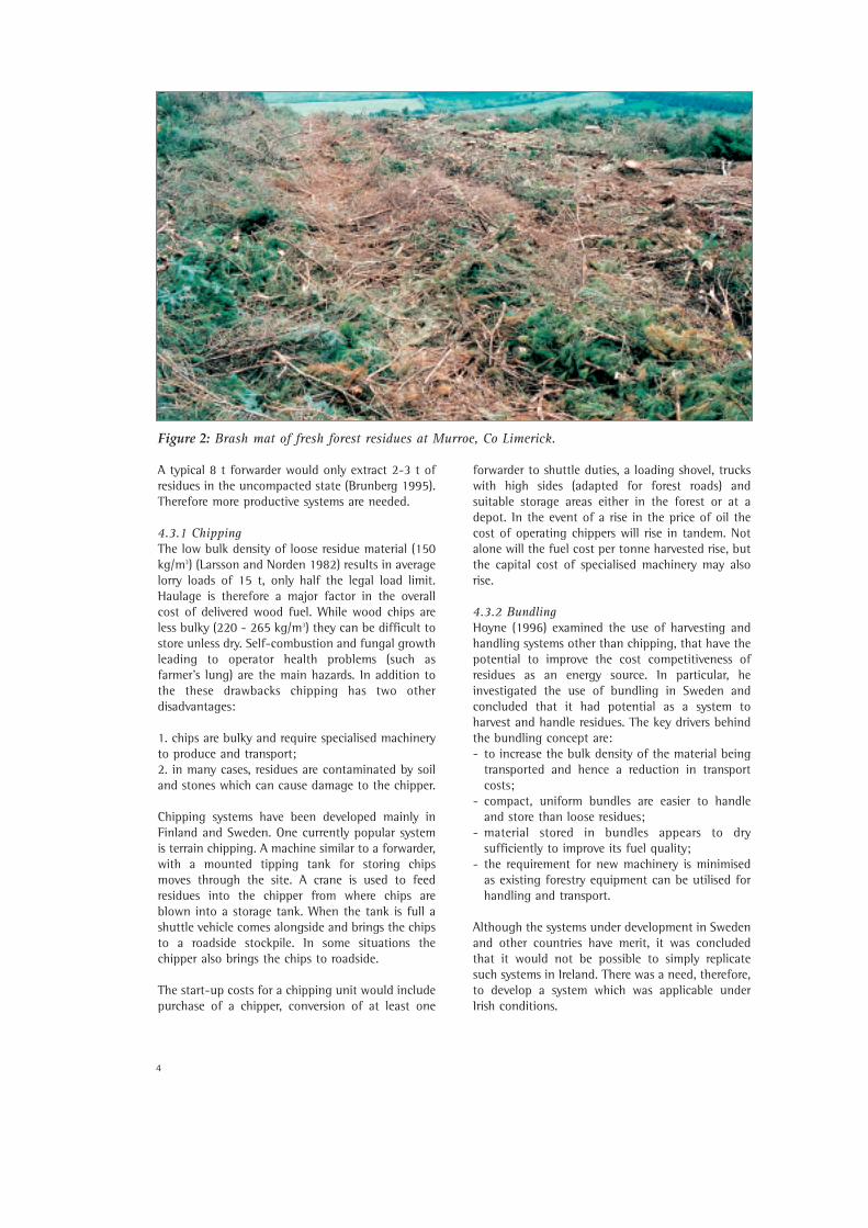
The literature review referred to found that bundlingof residues was potentially competitive withchipping and offered some possible advantages.Large bundles could be handled by conventionalmachinery. {For example, a logging truck could beeasily loaded and unloaded with bundles whereas itwould need special sides and a grapple to load andtransport chips (Figure 3).} Bundle density could beas good as or even better than chips and have theadvantage that bundles could be handled morecost-effectively. While chip piles have a bulk densityof 220-265 kg/m3 (see above) similar values havebeen achieved with compacted logging residues(Carlsson et al. 1980).
The most likely end use of forest residues wasconsidered to be heat energy generation, througheither combustion or gasification. The efficiency ofsuch processes is affected by the moisture contentof the material, as water must be evaporated duringthe conversion process. Conversion efficiency willtherefore increase as the moisture content of thematerial decreases. Forest residues stored loose inthe forest will dry over a period of time (Jirjis andLehtikanga 1993). It was hypothesised that bundledmaterial would also dry naturally when stored. In
addition, it was thought that material bundled atthe end of summer {20% m.c., wet basis (w.b.)}would be capable of withstanding storage overwinter without much deterioration. It was proposedto explore this concept with covered and uncoveredbundles. It also was proposed to determine the rateat which bundles dry once the weather improves inspring and summer. Reducing the moisture contentof the material using natural drying would help toincrease the efficiency of the conversion process andhence reduce costs.
At the outset of the project, it was not envisagedthat bundling of residues would replace chipping. Itwas considered, however, that bundling might havesome advantages where the residues werecontaminated by soil, extremely wet (50% m.c.,w.b.) or needed to be moved from the site some timebefore use, thus necessitating storage.
5.2 DEVELOPMENT OF THE DESIGN SPECIFICATION
FOR BUNDLING
Hoyne (1996) cited preliminary trials that had takenplace on fairly long thin bundles (4.0-5.0 m longand 0.4 m diameter). These appeared to have beenimpracticable (Hansen 1978, Carlsson et al. 1980).Some tests in uni-axial, lateral compaction had alsobeen conducted (Guimier 1985) but it was quitedifficult to see how these could be used in machinedesign. As a result of Hoyne’s (op. cit.) work, anhypothesis was developed that bundles, somewhatsimilar to those produced from hay, silage and straw,
Figure 3: Bundles of forest residue being unloaded from a wood haulage truck.
6
might be a suitable medium for transport andstorage of forest residues. Moreover, reducedcomminution prior to storage might lead to loweredrisk of self-combustion and lower levels of fungalgrowth as compared with chips.
As stated in the Objectives, one of the primary goalsof the project was to demonstrate that forestresidues, of the type commonly found in Ireland,could be successfully compacted into bundles. Indeveloping a specification for such bundles it wasnecessary to consider the material, the machineryavailable for compacting and handling residues,drying behaviour and mould growth, and end-use.
Bales and bundles are normally produced asrectangular prisms or cylinders. Rounded bundleshave a smaller circumference for a given sectionalarea, and are considered to be more dimensionallystable. Bales with triangular or rectangular crosssections have a larger circumference/volume ratio;there is a natural tendency in such solids to expandto minimise internal stresses.
The handling and harvesting of forest residues isaffected by the orientation of the material on theforest floor, which is determined by the harvestingmethod that is used. Motor-manual harvestingmethods tend to leave the material dispersed andrandomly orientated. Mechanical felling processesusually leave the residues in brash mats, as outlined.Residues in the mat are usually orientated in aparticular direction and are often contaminated bysoil. Hoyne (1996) determined that any newharvesting system should ensure that the handlingof the residues is kept to a minimum. Furthermore,it would be advantageous to have residuesorientated in the brash mat, or similar piles, toimprove handling.
In developing the design specification for thebundling machine, barriers to potentialcommercialisation and the high capital cost thatmight be associated with high levels of automationand power consumption were considered.Experimental work with a heavy, expensive, refusebaler in Sweden, which later became the ‘Bala’ balerwas noted (Bala 1995). Thus, it was decided to tryto develop a machine which was simple, consumeda minimum of power and was compatible withexisting haulage equipment.
In relation to having a low power consumption, itwas proposed that a machine that packed theresidues in a (generally) parallel orientation might bebest. This was based on the premise that breaking orcutting residues, to form a bundle would consumeadditional power and add complexity. It alsohypothesised that efficient packing of the material
would reduce the need for a high compaction forceand thus result in a lighter machine.
These considerations led to the development of thefollowing specification for the bundles:
1. shape: cylindrical with residues orientated alongthe main axis;
2. length: as long as possible, within the constraintsof handling and haulage. On Irish roads a loadwidth up to about 2.4 m is generally acceptable,provided no loose material protrudes beyond this, thus it was decided to have the bundles 2.4 m long;
3. diameter: such that logging equipment would beable to grip the bundle, 1.8 m appeared to be themaximum, but it could be as low as 1.0 m;
4. mass: should not exceed 80% of the liftingcapacity of forwarders at 2 m extension beyondthe wheelbase of the machine, approximately 1 t.A range of 0.5 to 2 t was assessed during the trials;
5. dimensional stability: tied or strapped tomaintain the shape of the bundle and to facilitate handling by conventional logginggrapples.
It was felt that a specification for the prototypeshould also allow a range of bundle sizes and types to be made. While such versatility could lead to complexity and higher cost, results from themanual bundling investigation gave workableestimates of the range of bundle sizes that could beexamined.
The following parameters were used in the design ofthe prototype bundler:
• loading: residue material to be loaded using aconventional logging grapple or similarequipment adapted for residues;
• orientation: residue orientation important to allow good compaction, machine to facilitateorientation of randomly arranged material;
• compaction force: the machine to exert a radialforce on the bundle of at least 150,000 N/m2 (seeSection 5.2.1);
• bundle ends: residues were loaded and compactedradially, consideration to be given to the need totrim and/or compact the ends of the bundles toprovide a tidy bundle to facilitate stacking and storage;
7
• strapping: bundle needed to be constrained toretain its shape and degree of compaction, astrapping arrangement to be devised to hold the bundles in place during storage and handling, theunit cost of such straps to be kept low, and madeto last for up to one year and be compatible withcombustion technologies;
• mounting: machine capable of being mountedonto an existing forwarder with the minimum ofmodification to either component, capable of being mounted and removed rapidly;
• gross weight: machine, with one full bundle, tobe within the capabilities of the forwarder interms of both weight and stability;
• overall height: height restricted to facilitateloading of residues by grapple arm and need for road transport on a low loader (to be within the clearance height of most bridges) - a maximum of3.5 m was initially proposed;
• automation: was considered but was not a priority for the prototype, however, to be capableof being operated from the forwarder cab, butacceptable to use manual fitting of restraining straps;
• safety: consideration was given to the safety of operatives and observers;
• durability: the machine was designed as aprototype and whilst it was robust, its working lifewas of the order of some hundreds of hours;
• instrumentation: no need for advanced instrumentation on the machine but an indicationof hydraulic pressure desirable to estimatecompaction forces;
• energy use: energy requirements for the handling,baling and bundling processes to be kept as lowas possible (taking into account the low energydensity of residues).
5.2.1 Establishing compaction forcesFollowing on the considerations outlined it wasdecided to develop a machine capable of makingbundles with diameters ranging from 1.2 m to 1.8 m,2.4 m in length. The magnitude of the force requiredto compact well oriented residues and the degree ofvolume reduction which might be achieved wereunknown. An experiment was designed to determinethe forces required to constrain and compactresidues. Previous workers (Guimier, 1985) had madecompaction samples but the data published did notappear to be applicable where radial compaction wasto be used. An experimental rig was designed based
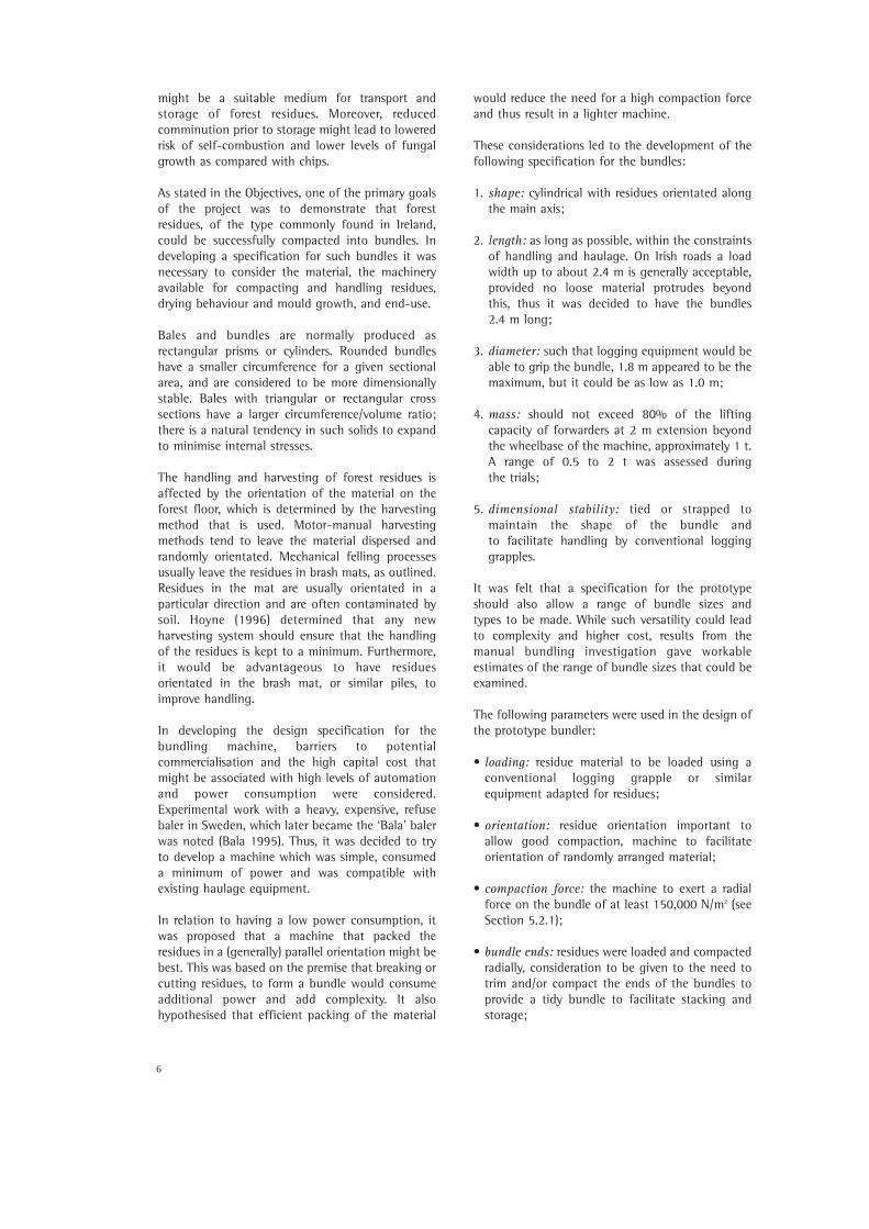
on a simple compaction framework, 2.5 m square(Figure 4). Green residues were placed in the frame,wrapped and secured with a number of bands. Thesewere tensioned manually using a ratchet and lever.The force required was measured as the size of theresidue bundle was reduced. Calculations of theband force and the mean diameter enabled thepressure exerted by the bundle to be estimated. Alinear regression was fitted which accuratelydescribed the relationship between the radialpressure applied and the volume reduction ratio(VRR).
Data from the manual bundling experiments wereused to determine the amount of energy required tocompact the residue material. At a particular point inthe compaction process, at an applied pressure of105 kPa and a volume reduction ratio (VRR) of 0.63,the total energy consumed in making the bundle was24 kJ. The bundle had a volume of 2.5 m3 and a drybulk density of 110 kg/m3, which equates to anenergy content of 10 kJ/m3. This gives an energyrequirement of 120 J/kg for an initial bulk density(dry) of 80 kg/m3. Thus, the energy needed tocompact a 1000 kg bundle to a VRR of 0.6 using thespecified bundler could be up to 120 kJ.
Guimier (1985) recorded tests on a number ofmachines for compacting residue materials. Using aVPI baler developed in the US, the energyrequirements were 590 J/kg (0.59 kJ/kg) to producebales with a green bulk density of 300 kg/m3 (VRR =0.5) from spruce residues. This was regarded as aconservative estimate (Guimier 1985). Guimier alsoreported data from Fridley (1981) of 1.18 kWh/t (4.3kJ/kg) required to compact (140 kg/m3) bales usinga modified Vermeer 605F hay baler (VRR unknown).This figure is quiet excessive when compared to datafrom other trials. It indicates that, as predicted,compacting material radially into a bundle formrequires less energy than methods which bend orbreak the material to form bales.
Figure 4: Manual bundling rig with strappedspecimen.
8
6. MACHINE DESIGN, BUILD ANDOPERATION
6.1 DESIGN
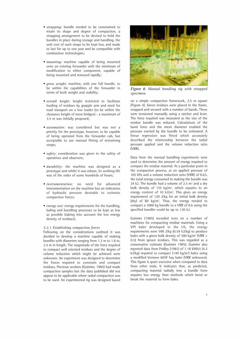
6.1.1 Location of the bundler and mounting onforwarderA number of locations were considered for operatingthe bundler. Initially, it was thought that theprototype might operate at the roadside (possibly ona low-loader) and be fed by a forwarder. As theproject evolved it became clear, however, thatroadside work was unrealistic, and not necessarilycheaper, as it involved additional tractors, cranesand low-loaders. The emphasis was, therefore, on adesign which could be adapted to fit onto aforwarder.
The final prototype design (Figures 5 and 6) had aflat base. This was a compromise based on the
original roadside concept and the fact that theshape of forwarders available to the project variedconsiderably.
6.1.2 Orientation on forwarder The prototype bundler had to comply with the tightspecifications outlined and fit within the spacenormally occupied by the wood load on theforwarder, as well as producing a bundle of givendimensions.
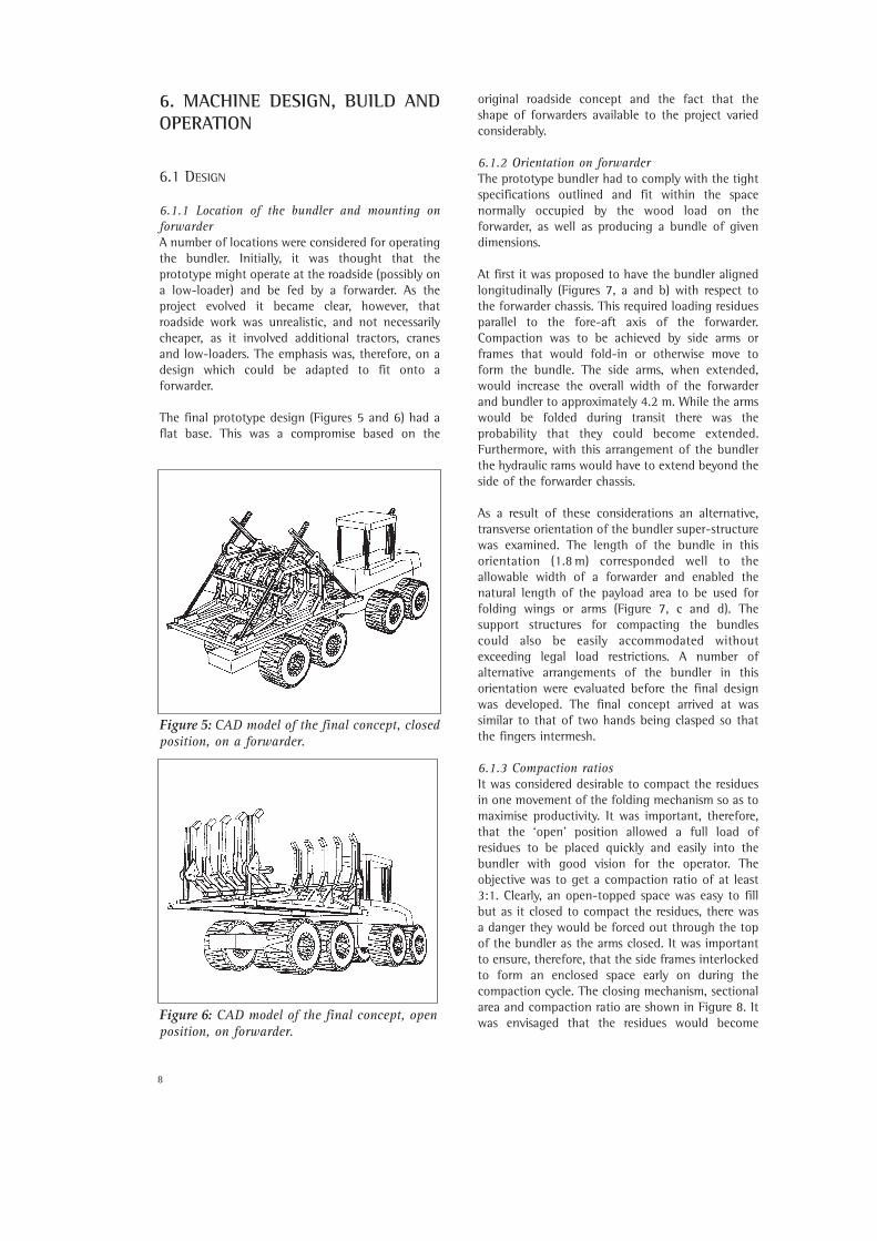
At first it was proposed to have the bundler alignedlongitudinally (Figures 7, a and b) with respect tothe forwarder chassis. This required loading residuesparallel to the fore-aft axis of the forwarder.Compaction was to be achieved by side arms orframes that would fold-in or otherwise move toform the bundle. The side arms, when extended,would increase the overall width of the forwarderand bundler to approximately 4.2 m. While the armswould be folded during transit there was theprobability that they could become extended.Furthermore, with this arrangement of the bundlerthe hydraulic rams would have to extend beyond theside of the forwarder chassis.
As a result of these considerations an alternative,transverse orientation of the bundler super-structurewas examined. The length of the bundle in thisorientation (1.8 m) corresponded well to theallowable width of a forwarder and enabled thenatural length of the payload area to be used forfolding wings or arms (Figure 7, c and d). Thesupport structures for compacting the bundlescould also be easily accommodated withoutexceeding legal load restrictions. A number ofalternative arrangements of the bundler in thisorientation were evaluated before the final designwas developed. The final concept arrived at wassimilar to that of two hands being clasped so thatthe fingers intermesh.
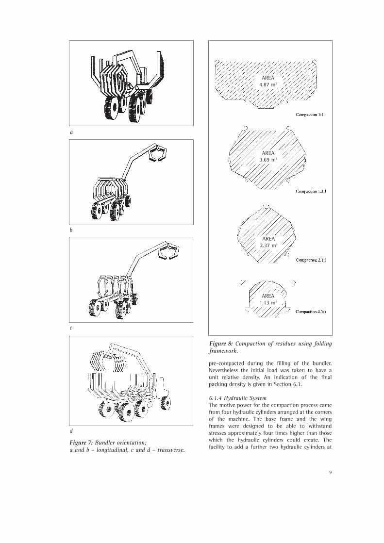
6.1.3 Compaction ratiosIt was considered desirable to compact the residuesin one movement of the folding mechanism so as tomaximise productivity. It was important, therefore,that the ‘open’ position allowed a full load ofresidues to be placed quickly and easily into thebundler with good vision for the operator. Theobjective was to get a compaction ratio of at least3:1. Clearly, an open-topped space was easy to fillbut as it closed to compact the residues, there wasa danger they would be forced out through the topof the bundler as the arms closed. It was importantto ensure, therefore, that the side frames interlockedto form an enclosed space early on during thecompaction cycle. The closing mechanism, sectionalarea and compaction ratio are shown in Figure 8. Itwas envisaged that the residues would become
Figure 6: CAD model of the final concept, openposition, on forwarder.
Figure 5: CAD model of the final concept, closedposition, on a forwarder.
9
pre-compacted during the filling of the bundler.Nevertheless the initial load was taken to have aunit relative density. An indication of the finalpacking density is given in Section 6.3.
6.1.4 Hydraulic SystemThe motive power for the compaction process camefrom four hydraulic cylinders arranged at the cornersof the machine. The base frame and the wingframes were designed to be able to withstandstresses approximately four times higher than thosewhich the hydraulic cylinders could create. Thefacility to add a further two hydraulic cylinders at
Figure 7: Bundler orientation; a and b – longitudinal, c and d – transverse.
d
Figure 8: Compaction of residues using foldingframework.
b
c
a
AREA4.87 m2
AREA3.69 m2
AREA2.37 m2
AREA1.13 m2
10
the centre of the machine was incorporated in thedesign scheme. One of the versatile features of theprototype comes from the ability to use hydraulicpressure from a tractor, forwarder or independentpower pack. The cylinders were specified to work atup to 200 bar (3000 psi) but in practice someforwarders are not able to provide pressure above130 bar (2000 psi). The cylinders were inverted andtrunnion-mounted to make them more compactand to maximise the force at the closed position.This introduced problems with hoses which weresubject to damage in service.
For further development of the bundler, relocationof the cylinders and an alternative to the flat base,in order to fit the bundler to specific forwarders,should be addressed. This should enable the bundlerto be lowered by as much as 400 mm, therebyimproving stability and making loading easier.
6.1.5 End trimmingThe issue of how to deal with the ends of thebundles was not resolved and the bundle ends wereleft untrimmed and unconstrained in the firstprototype. However, a number of potentialmechanisms were considered. Moving baffles mightpush the bundle ends into place as the radialcompaction occurred, but it was not known how thematerial would move axially. Material exceeding 2.4m might need cutting or breaking to make it fit tothe bundle dimensions.
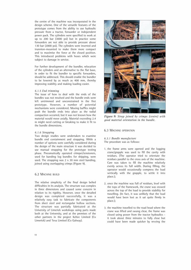
6.1.6 StrappingTwo design studies were undertaken to examinebundle end containment and strapping. While anumber of options were carefully considered duringthe design of the main structure it was decided touse manual strapping for the prototype testingphase. Pneumatically operated crimper/tensioners,used for banding log bundles for shipping, wereused. The strapping was 2 x 30 mm steel banding,joined using overlapping crimps (Figure 9).
6.2 MACHINE BUILD
The relative simplicity of the final design belieddifficulties in its analysis. The structure was complexin three dimensions and caused some concern inrelation to its rigidity. However, once the detaileddesign was completed successfully, it was arelatively easy task to fabricate the componentsfrom sheet steel and rectangular hollow sections.The structure was partially fabricated at theUniversity of Limerick workshops using parts madeboth at the University, and at the premises of theother partners in the project Keltec Limited (CoLimerick) and Teva Limited (Co Galway).
6.3 MACHINE OPERATION
6.3.1 Bundle manufacture The procedure was as follows:
1. the frame arms were opened and the loggingcrane/grapple was used to fill the cavity with residues. (The operator tried to orientate the residues parallel to the cross axis of the machine. Care was taken to fill the machine relativelyevenly across its full width. During filling, theoperator would occasionally compress the loadvertically with the grapple, to settle it intoplace.);
2. once the machine was full of residues, level withthe tops of the framework, the crane was stowed across the top of the load to provide stability fortravelling. (In fact, it was unlikely that the loadwould have been lost as it sat quite firmly inplace.);
3. the machine travelled to the road head where thecrane was lifted and swung clear, the frame wasclosed using power from the tractor hydraulics -it took about three minutes to fully close butcould have been made quicker by revving the
Figure 9: Strap joined by crimps (centre) withgood material orientation in the bundle.
11
tractor engine at a greater speed. (Hydraulicpressure readings were taken as the closureoccurred so that the forces and energy required for compaction were measured.);
4. when the bundle was fully formed the strappingwas manually fitted at two points around thebundle, about 2 m apart;
5. the arms were opened and the bundle was removed, weighed and stacked.
The average cycle time to produce a bundle variedbetween 0.5 - 0.75 hr depending on the extractiondistance.
6.3.2 Varying bundle size and compaction ratioThe bundler was designed in such a way thatadditional components could be fitted to make asmaller bundle if required. Once in the field, it wasfound that the bundle size could be varied to someextent without these additions. To make a largerbundle, the machine was overfilled and as there wasnot sufficient force for the machine to becompletely closed, the bundle had a larger diameter.It was still possible to strap the bundle adequatelybut the increased diameter was very difficult tograsp. Smaller bundles were made by only partiallyfilling the machine and using the strappingtensioner to get a good reduction in diameter. Thiswas not very successful, as the bundle tended to beloose and hence easily damaged. The cycle timesvaried very little (0.50-0.75 hr) so the heavier thebundle the greater the productivity.
As indicated in Section 6.1.3, the compaction ratiowas estimated to be approximately 3:1. Thisrepresented the geometrical ratio available in themachine and the force of the hydraulics was
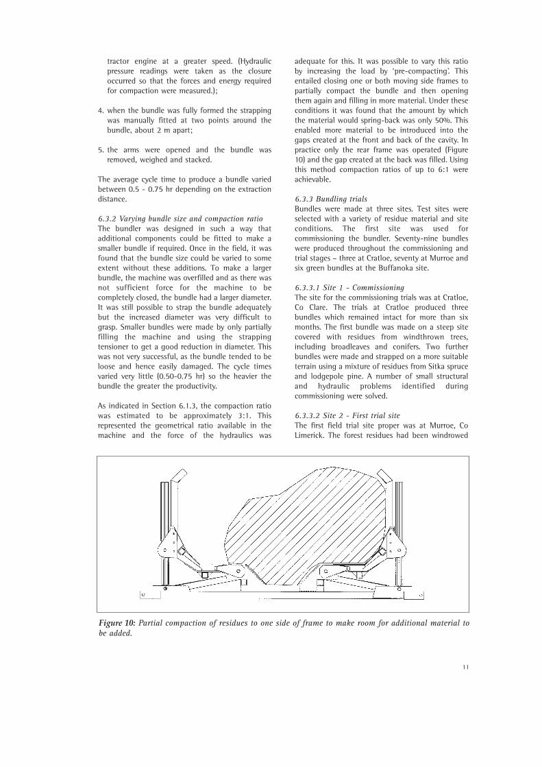
adequate for this. It was possible to vary this ratioby increasing the load by ‘pre-compacting’. Thisentailed closing one or both moving side frames topartially compact the bundle and then openingthem again and filling in more material. Under theseconditions it was found that the amount by whichthe material would spring-back was only 50%. Thisenabled more material to be introduced into thegaps created at the front and back of the cavity. Inpractice only the rear frame was operated (Figure10) and the gap created at the back was filled. Usingthis method compaction ratios of up to 6:1 wereachievable.
6.3.3 Bundling trials Bundles were made at three sites. Test sites wereselected with a variety of residue material and siteconditions. The first site was used forcommissioning the bundler. Seventy-nine bundleswere produced throughout the commissioning andtrial stages – three at Cratloe, seventy at Murroe andsix green bundles at the Buffanoka site.
6.3.3.1 Site 1 - CommissioningThe site for the commissioning trials was at Cratloe,Co Clare. The trials at Cratloe produced threebundles which remained intact for more than sixmonths. The first bundle was made on a steep sitecovered with residues from windthrown trees,including broadleaves and conifers. Two furtherbundles were made and strapped on a more suitableterrain using a mixture of residues from Sitka spruceand lodgepole pine. A number of small structuraland hydraulic problems identified duringcommissioning were solved.
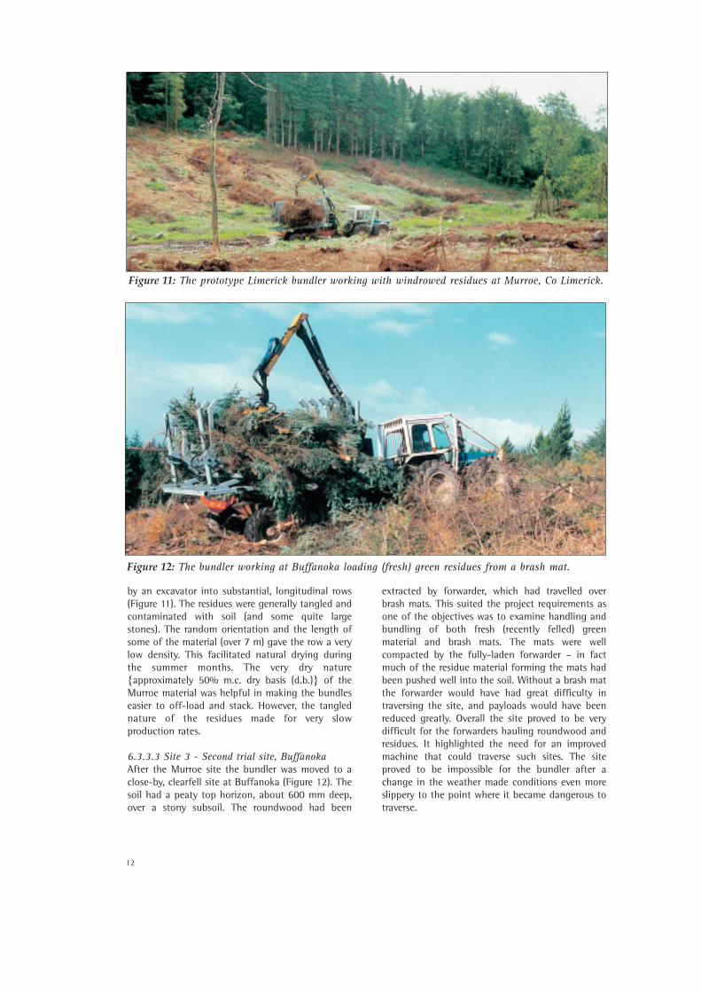
6.3.3.2 Site 2 - First trial site The first field trial site proper was at Murroe, CoLimerick. The forest residues had been windrowed
Figure 10: Partial compaction of residues to one side of frame to make room for additional material tobe added.
12
by an excavator into substantial, longitudinal rows(Figure 11). The residues were generally tangled andcontaminated with soil (and some quite largestones). The random orientation and the length ofsome of the material (over 7 m) gave the row a verylow density. This facilitated natural drying duringthe summer months. The very dry nature{approximately 50% m.c. dry basis (d.b.)} of theMurroe material was helpful in making the bundleseasier to off-load and stack. However, the tanglednature of the residues made for very slowproduction rates.
6.3.3.3 Site 3 - Second trial site, BuffanokaAfter the Murroe site the bundler was moved to aclose-by, clearfell site at Buffanoka (Figure 12). Thesoil had a peaty top horizon, about 600 mm deep,over a stony subsoil. The roundwood had been
extracted by forwarder, which had travelled overbrash mats. This suited the project requirements asone of the objectives was to examine handling andbundling of both fresh (recently felled) greenmaterial and brash mats. The mats were wellcompacted by the fully-laden forwarder – in factmuch of the residue material forming the mats hadbeen pushed well into the soil. Without a brash matthe forwarder would have had great difficulty intraversing the site, and payloads would have beenreduced greatly. Overall the site proved to be verydifficult for the forwarders hauling roundwood andresidues. It highlighted the need for an improvedmachine that could traverse such sites. The siteproved to be impossible for the bundler after achange in the weather made conditions even moreslippery to the point where it became dangerous totraverse.
Figure 11: The prototype Limerick bundler working with windrowed residues at Murroe, Co Limerick.
Figure 12: The bundler working at Buffanoka loading (fresh) green residues from a brash mat.
13
7. HANDLING, HAULAGE, STORAGEAND ANALYSIS OF BUNDLES
7.1 HANDLING AND HAULAGE
The bundles were handled frequently duringmanufacture and stacking, and while beingmeasured (Table 1). The machinery used forhandling included a forwarder (unloading, stackingand weighing), a loader (stacking and loading ontruck) and truck crane (unloading and stacking).Most bundles were handled 12 times (Table 1) but
some were handled more frequently due to beingstacked vertically or re-arranged on the stack.
The bundles were hauled using conventionalforestry trucks (Figure 3).
7.2 DETERMINATION OF BUNDLE WEIGHT
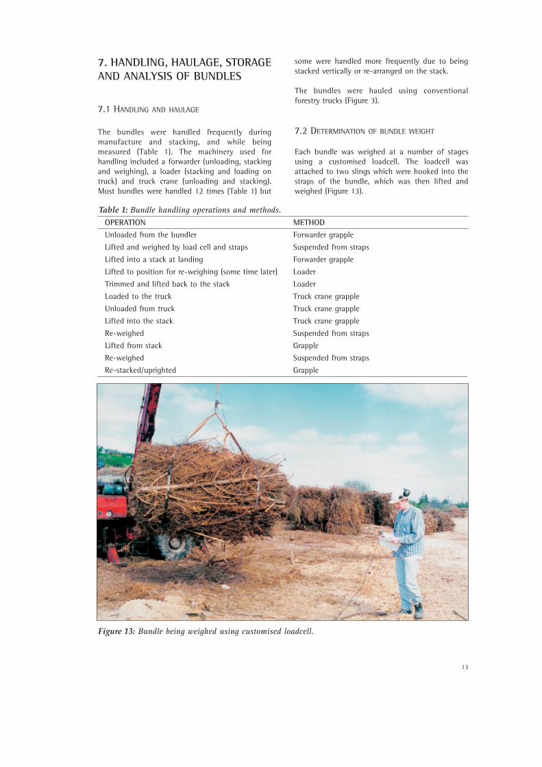
Each bundle was weighed at a number of stagesusing a customised loadcell. The loadcell wasattached to two slings which were hooked into thestraps of the bundle, which was then lifted andweighed (Figure 13).
OPERATION METHOD
Unloaded from the bundler Forwarder grapple
Lifted and weighed by load cell and straps Suspended from straps
Lifted into a stack at landing Forwarder grapple
Lifted to position for re-weighing (some time later) Loader
Trimmed and lifted back to the stack Loader
Loaded to the truck Truck crane grapple
Unloaded from truck Truck crane grapple
Lifted into the stack Truck crane grapple
Re-weighed Suspended from straps
Lifted from stack Grapple
Re-weighed Suspended from straps
Re-stacked/uprighted Grapple
Table 1: Bundle handling operations and methods.
Figure 13: Bundle being weighed using customised loadcell.
14
7.3 TRIMMING
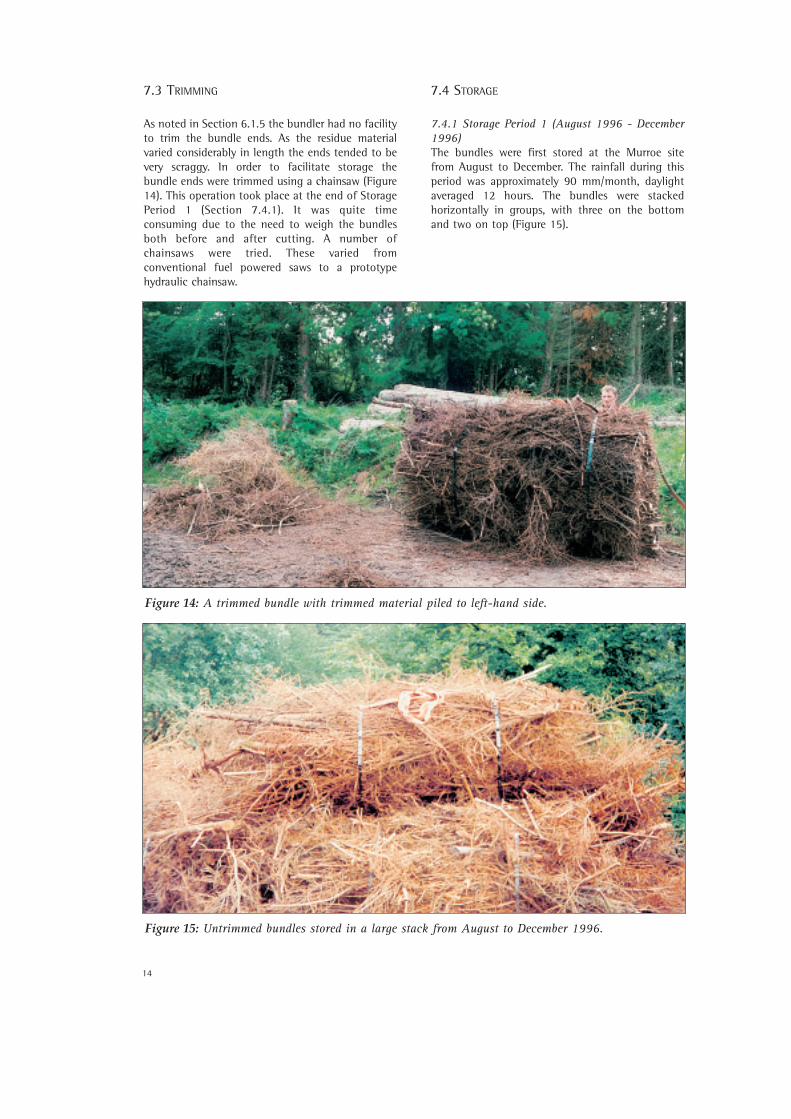
As noted in Section 6.1.5 the bundler had no facilityto trim the bundle ends. As the residue materialvaried considerably in length the ends tended to bevery scraggy. In order to facilitate storage thebundle ends were trimmed using a chainsaw (Figure14). This operation took place at the end of StoragePeriod 1 (Section 7.4.1). It was quite timeconsuming due to the need to weigh the bundlesboth before and after cutting. A number ofchainsaws were tried. These varied fromconventional fuel powered saws to a prototypehydraulic chainsaw.
7.4 STORAGE
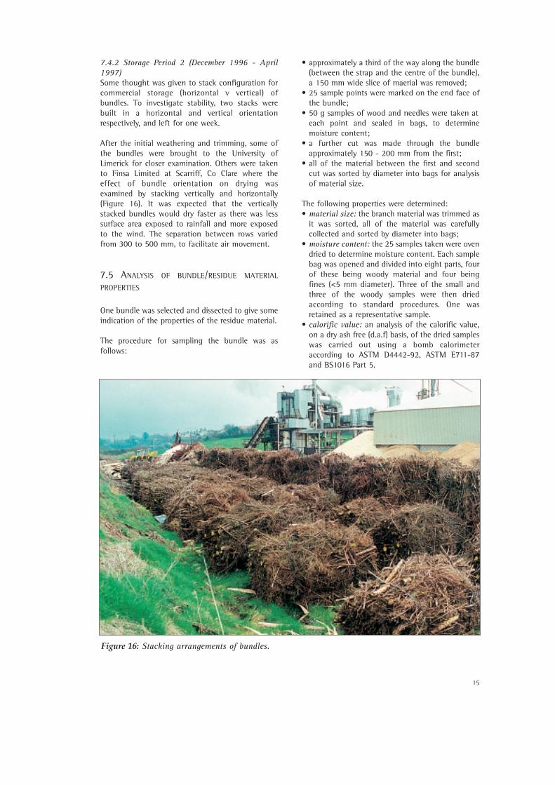
7.4.1 Storage Period 1 (August 1996 - December1996)The bundles were first stored at the Murroe sitefrom August to December. The rainfall during thisperiod was approximately 90 mm/month, daylightaveraged 12 hours. The bundles were stackedhorizontally in groups, with three on the bottomand two on top (Figure 15).
Figure 15: Untrimmed bundles stored in a large stack from August to December 1996.
Figure 14: A trimmed bundle with trimmed material piled to left-hand side.
15
7.4.2 Storage Period 2 (December 1996 - April1997)Some thought was given to stack configuration forcommercial storage (horizontal v vertical) ofbundles. To investigate stability, two stacks werebuilt in a horizontal and vertical orientationrespectively, and left for one week.
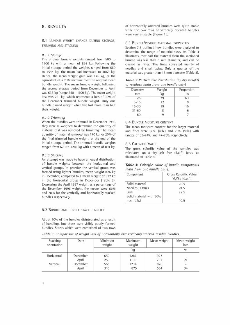
After the initial weathering and trimming, some ofthe bundles were brought to the University ofLimerick for closer examination. Others were takento Finsa Limited at Scarriff, Co Clare where theeffect of bundle orientation on drying wasexamined by stacking vertically and horizontally(Figure 16). It was expected that the verticallystacked bundles would dry faster as there was lesssurface area exposed to rainfall and more exposedto the wind. The separation between rows variedfrom 300 to 500 mm, to facilitate air movement.
7.5 ANALYSIS OF BUNDLE/RESIDUE MATERIAL
PROPERTIES
One bundle was selected and dissected to give someindication of the properties of the residue material.
The procedure for sampling the bundle was asfollows:
• approximately a third of the way along the bundle(between the strap and the centre of the bundle),a 150 mm wide slice of maerial was removed;
• 25 sample points were marked on the end face ofthe bundle;
• 50 g samples of wood and needles were taken at each point and sealed in bags, to determinemoisture content;
• a further cut was made through the bundleapproximately 150 - 200 mm from the first;
• all of the material between the first and second cut was sorted by diameter into bags for analysisof material size.
The following properties were determined: • material size: the branch material was trimmed as
it was sorted, all of the material was carefullycollected and sorted by diameter into bags;
• moisture content: the 25 samples taken were ovendried to determine moisture content. Each samplebag was opened and divided into eight parts, four of these being woody material and four beingfines (<5 mm diameter). Three of the small andthree of the woody samples were then dried according to standard procedures. One wasretained as a representative sample.
• calorific value: an analysis of the calorific value, on a dry ash free (d.a.f) basis, of the dried samples was carried out using a bomb calorimeter according to ASTM D4442-92, ASTM E711-87and BS1016 Part 5.
Figure 16: Stacking arrangements of bundles.
16
8. RESULTS
8.1 BUNDLE WEIGHT CHANGE DURING STORAGE,TRIMMING AND STACKING
8.1.1 StorageThe original bundle weights ranged from 500 to1200 kg with a mean of 893 kg. Following theinitial storage period the weights ranged from 660to 1544 kg, the mean had increased to 1069 kg.Hence, the mean weight gain was 176 kg, or theequivalent of a 20% increase over the original meanbundle weight. The mean bundle weight followingthe second storage period from December to Aprilwas 636 kg (range 250 - 1100 kg). The mean weightloss was 261 kg, which represents a loss of 30% ofthe December trimmed bundle weight. Only onebundle gained weight while five lost more than halftheir weight.
8.1.2 TrimmingWhen the bundles were trimmed in December 1996they were re-weighed to determine the quantity ofmaterial that was removed by trimming. The meanquantity of material removed was 170 kg, or 20% ofthe final trimmed bundle weight, at the end of theinitial storage period. The trimmed bundle weightsranged from 620 to 1286 kg with a mean of 891 kg.
8.1.3 StackingAn attempt was made to have an equal distributionof bundle weights between the horizontal andvertical groups. In practice the vertical group wasformed using lighter bundles, mean weight 826 kgin December, compared to a mean weight of 927 kgin the horizontal group in December (Table 2).Expressing the April 1997 weight as a percentage ofthe December 1996 weight, the means were 66%and 78% for the vertically and horizontally stackedbundles respectively.
8.2 BUNDLE AND BUNDLE STACK STABILITY
About 10% of the bundles disintegrated as a resultof handling, but these were visibly poorly formedbundles. Stacks which were comprised of two rows
of horizontally oriented bundles were quite stablewhile the two rows of vertically oriented bundleswere very unstable (Figure 15).
8.3 BUNDLE/RESIDUE MATERIAL PROPERTIESSection 7.5 outlined how bundles were analysed todetermine the range of material sizes. As Table 3illustrates, over half the material from the sectionedbundle was less than 5 mm diameter, and can beclassed as fines. The fines consisted mainly ofneedles and small twigs. Only a quarter of thematerial was greater than 15 mm diameter (Table 3).
8.4 BUNDLE MOISTURE CONTENTThe mean moisture content for the larger materialand fines were 50% (w.b.) and 70% (w.b.) withranges of 33-74% and 47-78% respectively.
8.5 CALORIFIC VALUEThe gross calorific value of the samples wascalculated on a dry ash free (d.a.f.) basis, asillustrated in Table 4.
Stackingorientation
Date Minimumweight
Maximum weight
kg
Mean weight Mean weight loss%
650250555310
DecemberApril
DecemberApril
Horizontal
Vertical
128611001234875
927733826554
-21-
34
Table 2: Comparison of weight loss of horizontally and vertically stacked residue bundles.
Diameter mm<5
5-1516-3031-60
60
Weight kg79121989
Proportion %639
1567
Table 3: Particle size distribution (by dry weight)of residues (data from one bundle only)
Component
Solid materialNeedles & finesBarkSolid material with 30%m.c. (d.b.)
Gross Calorific Value MJ/kg (d.a.f.)
20.521.522.5
10.5
Table 4: Calorific value of bundle components(data from one bundle only).
17
9. DISCUSSION
9.1 MACHINE OPERATION
The bundler and forwarder operated without anymajor problems during the trials. Indeed, themajority of difficulties were caused because thebundler was originally designed to be a landingbased machine and was modified at a late stage inthe design process to be attached to the forwarder.This meant that there were some problems withstability, the crane position and hydraulic systems.
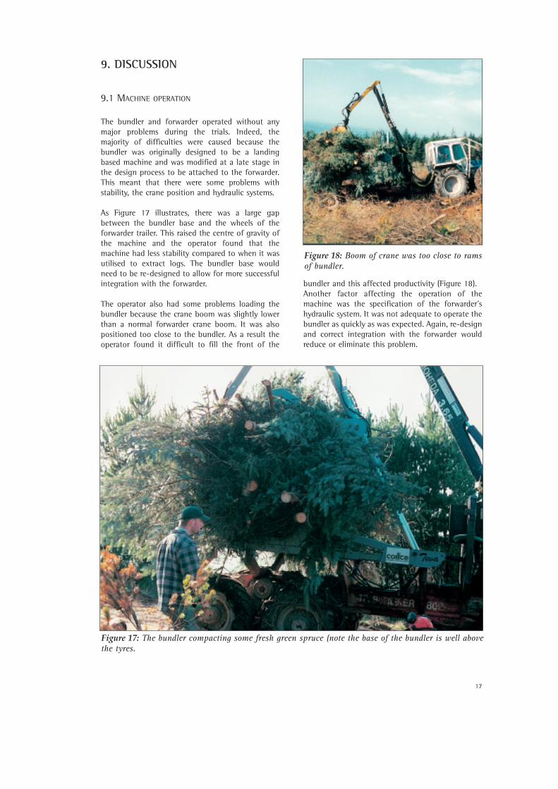
As Figure 17 illustrates, there was a large gapbetween the bundler base and the wheels of theforwarder trailer. This raised the centre of gravity ofthe machine and the operator found that themachine had less stability compared to when it wasutilised to extract logs. The bundler base wouldneed to be re-designed to allow for more successfulintegration with the forwarder.
The operator also had some problems loading thebundler because the crane boom was slightly lowerthan a normal forwarder crane boom. It was alsopositioned too close to the bundler. As a result theoperator found it difficult to fill the front of the
bundler and this affected productivity (Figure 18). Another factor affecting the operation of themachine was the specification of the forwarder’shydraulic system. It was not adequate to operate thebundler as quickly as was expected. Again, re-designand correct integration with the forwarder wouldreduce or eliminate this problem.
Figure 17: The bundler compacting some fresh green spruce (note the base of the bundler is well abovethe tyres.
Figure 18: Boom of crane was too close to ramsof bundler.
18
As expected, the strapping process presented someproblems as it was carried out manually and thepneumatic equipment was rather unwieldy.However, considerable experience was gained onstrap positioning and movement as the bundlerarms closed. Progress has been ongoing in anattempt to develop alternative strapping systemswhich can be semi-automated and which use strapsthat are recyclable and/or re-usable.
9.2 PRODUCTION OF BUNDLES AND PERFORMANCE
OF BUNDLER ON DIFFERENT SITES
In terms of first effort, the Cratloe trials weresuccessful in that residues were bundled at the firstattempt. They were 1.6 m diameter, cylindrical and3 m long and contained over 1 t of material.Considering how dry the material was, (approx. 50%m.c., d.b.), this represented more material thananticipated. The bundle ends were however, veryscraggy and no method of solving this problem hadbeen developed to date.
The work at Murroe was more demanding as the sitewas sloping and very wet in the middle where themain extraction route was located. The largenumber of substantial timber lengths slowedprogress as each had to be cut or broken. Manualcutting of the pieces of wood was not possible inmost cases because of their position within thewindrow. Also, to facilitate the experimental work,the forwarder was bringing each load out to thelanding for strapping and weighing. Thus, over halfthe cycle time (and in some cases two thirds) waswasted travelling unnecessarily over the site. Thepreferred mode of operation would have been tomake the bundle alongside the windrow, strap andunload it for later collection by a modifiedforwarder capable of carrying up to six bundles at atime.
The trials at Buffanoka were disappointing. It rainedheavily shortly after the machine arrived on-site andthis added to the problems of dealing with a peatysoil. An experimental ‘fixed side’ had been fitted tothe machine to attempt to produce bundles withone flat end. The additional weight proved toomuch for the ground to support. Furthermore itshifted the centre of gravity of the machine, makingit unstable. The forwarder had, of necessity, to traveloff the brash mat in order to harvest it and thisproved to be very difficult. Uphill progress wasalmost impossible, even with chains on the tyres,and downhill travel was dangerous as the sitebecame progressively steeper, culminating in a drop,as it approached the forest road. About 10% of treeshad been manually felled at the site, as they weretoo large to be felled by machine. The resulting
stumps were quiet high, and this restrictedforwarder travel. Deep plough furrows alsocontributed to the difficulty of traversing the site.However, the design team gained valuableexperience about the needs of a forwarder on suchterrain and, in the circumstances, a lot of lessonswere learned. It was primarily on safety grounds thatwork stopped at the site.
Overall at the two sites productivity was veryvariable. Generally only about ten bundles weremade and delivered to the road-head per day.Considering the nature of the material and theextraction conditions, an improvement inproductivity to 40-50 bundles per day could beexpected following improvements to the strappingmechanism. Furthermore, an initial assessment ofthe productivity and economic feasibility of anumber of forest residue bundling systems carriedout by Hoyne (1996) showed that one system wherebundles are extracted one at a time to roadside wasone of the most unproductive of all the systems heanalysed. A system (op. cit.) that unloads thebundles as they are produced - to be extracted laterusing a modified forwarder carrying up to sixbundles - should be the most economic andproductive terrain bundling system. Further workwould be required to support this study with fielddata.
9.3 BUNDLE MANUFACTURE
The bundles had diameters ranging from 1.2 to 1.6 m with a mean weight of approximately 900 kg(Section 8.1). In practice, a compaction ratio of 4:1was achieved and the hydraulic force was adequateto achieve this.
As noted in Section 6.3.2, the bundle compactionratio was varied by pre-compacting the material byclosing and opening the frame, to partially compactthe material, and then loading more material intothe gaps left in the front and back. This method metwith a varying degree of success. As noted, thegrapple/crane of the forwarder was too close to thefront of the bundler, having been designed to loadlogs at the middle of the machine, and therefore itcould not reach fully to the front to fill the gapcreated. Operating just the rear frame and thenfilling the gap at the back solved this problem.However, this introduced a second problem as theoperator, not having very good visibility, couldintroduce too much material, the equivalent to a 6:1compaction ratio, and the hydraulic rams were notable to provide sufficient force to fully close theframes. Thus, it is estimated that the bestcompaction achieved was of the order of 5:1, usinga two-phase compacting cycle.
19
9.4 TRIMMING OF BUNDLES
Although the bundles had relatively consistentdiameters and were cylindrical in shape the endswere uneven and scraggy. The attempt, at theBuffanoka site, as described, to produce bundleswith one flat end, was unsuccessful, and thebundles were trimmed manually. The trimmingoperation was carried out at the end of the initialstorage period in December 1996 and as described,a number of chainsaws were used to trim thebundles. However, it was found that the trimmingoperation was hazardous. The chains suffered wearas some of the inner material tended to move aboutand because the residues contained soil and stones.
The most successful saw used was a prototypehydraulic chainsaw. It was successful at cutting butlacked the safety features normally associated withpetrol saws. It was fitted with a coarse pitch chainof very good quality material, which needed lesssharpening than conventional saws. The workdemonstrated that chainsaws could be used for end-trimming of the bundles but they would needdevelopment and would need to be placed on themachine and properly housed to prevent accidentaldamage.
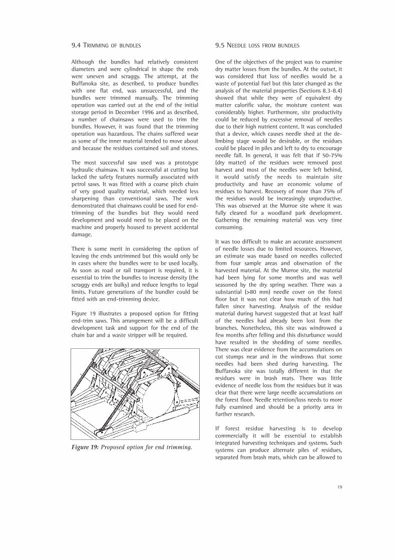
There is some merit in considering the option ofleaving the ends untrimmed but this would only bein cases where the bundles were to be used locally.As soon as road or rail transport is required, it isessential to trim the bundles to increase density (thescraggy ends are bulky) and reduce lengths to legallimits. Future generations of the bundler could befitted with an end-trimming device.
Figure 19 illustrates a proposed option for fittingend-trim saws. This arrangement will be a difficultdevelopment task and support for the end of thechain bar and a waste stripper will be required.
9.5 NEEDLE LOSS FROM BUNDLES
One of the objectives of the project was to examinedry matter losses from the bundles. At the outset, itwas considered that loss of needles would be awaste of potential fuel but this later changed as theanalysis of the material properties (Sections 8.3-8.4)showed that while they were of equivalent drymatter calorific value, the moisture content wasconsiderably higher. Furthermore, site productivitycould be reduced by excessive removal of needlesdue to their high nutrient content. It was concludedthat a device, which causes needle shed at the de-limbing stage would be desirable, or the residuescould be placed in piles and left to dry to encourageneedle fall. In general, it was felt that if 50-75%(dry matter) of the residues were removed postharvest and most of the needles were left behind, it would satisfy the needs to maintain siteproductivity and have an economic volume ofresidues to harvest. Recovery of more than 75% ofthe residues would be increasingly unproductive.This was observed at the Murroe site where it wasfully cleared for a woodland park development.Gathering the remaining material was very timeconsuming.
It was too difficult to make an accurate assessmentof needle losses due to limited resources. However,an estimate was made based on needles collectedfrom four sample areas and observation of theharvested material. At the Murroe site, the materialhad been lying for some months and was wellseasoned by the dry spring weather. There was asubstantial (>80 mm) needle cover on the forestfloor but it was not clear how much of this hadfallen since harvesting. Analysis of the residuematerial during harvest suggested that at least halfof the needles had already been lost from thebranches. Nonetheless, this site was windrowed afew months after felling and this disturbance wouldhave resulted in the shedding of some needles.There was clear evidence from the accumulations oncut stumps near and in the windrows that someneedles had been shed during harvesting. TheBuffanoka site was totally different in that theresidues were in brash mats. There was littleevidence of needle loss from the residues but it wasclear that there were large needle accumulations onthe forest floor. Needle retention/loss needs to morefully examined and should be a priority area infurther research.
If forest residue harvesting is to developcommercially it will be essential to establishintegrated harvesting techniques and systems. Suchsystems can produce alternate piles of residues,separated from brash mats, which can be allowed to
Figure 19: Proposed option for end trimming.
20
dry and harvested with more ease. As stated,residues should preferably be left on site for a periodof time, following the roundwood harvest tofacilitate needle shedding.
9.6 HANDLING AND HAULAGE OF BUNDLES
Only 10% of the bundles produced disintegrated(Section 8.2) during handling and these were badlymade bundles. Most damage occurred during thetrimming process. The handling of the bundles wasdone by means of an articulated industrial loader,fitted with a silage fork.
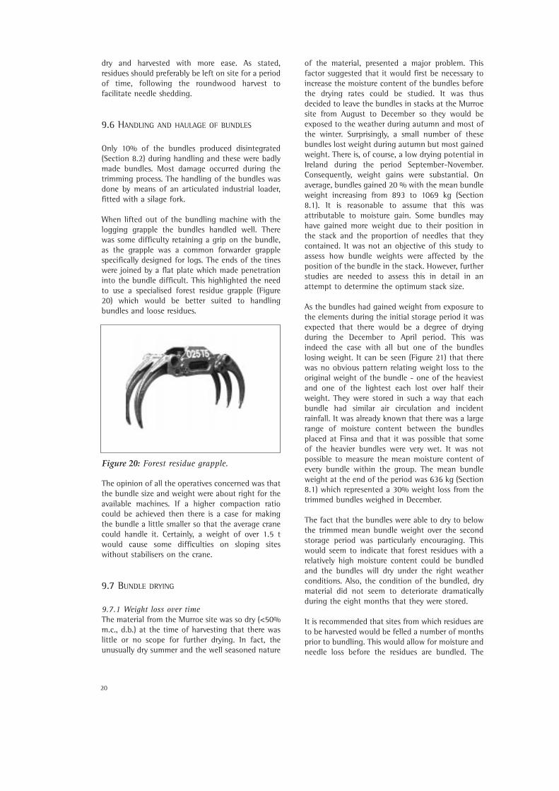
When lifted out of the bundling machine with thelogging grapple the bundles handled well. Therewas some difficulty retaining a grip on the bundle,as the grapple was a common forwarder grapplespecifically designed for logs. The ends of the tineswere joined by a flat plate which made penetrationinto the bundle difficult. This highlighted the needto use a specialised forest residue grapple (Figure20) which would be better suited to handlingbundles and loose residues.
The opinion of all the operatives concerned was thatthe bundle size and weight were about right for theavailable machines. If a higher compaction ratiocould be achieved then there is a case for makingthe bundle a little smaller so that the average cranecould handle it. Certainly, a weight of over 1.5 twould cause some difficulties on sloping siteswithout stabilisers on the crane.
9.7 BUNDLE DRYING
9.7.1 Weight loss over timeThe material from the Murroe site was so dry (<50%m.c., d.b.) at the time of harvesting that there waslittle or no scope for further drying. In fact, theunusually dry summer and the well seasoned nature
of the material, presented a major problem. Thisfactor suggested that it would first be necessary toincrease the moisture content of the bundles beforethe drying rates could be studied. It was thusdecided to leave the bundles in stacks at the Murroesite from August to December so they would beexposed to the weather during autumn and most ofthe winter. Surprisingly, a small number of thesebundles lost weight during autumn but most gainedweight. There is, of course, a low drying potential inIreland during the period September-November.Consequently, weight gains were substantial. Onaverage, bundles gained 20 % with the mean bundleweight increasing from 893 to 1069 kg (Section8.1). It is reasonable to assume that this wasattributable to moisture gain. Some bundles mayhave gained more weight due to their position inthe stack and the proportion of needles that theycontained. It was not an objective of this study toassess how bundle weights were affected by theposition of the bundle in the stack. However, furtherstudies are needed to assess this in detail in anattempt to determine the optimum stack size.
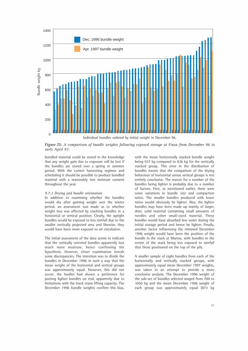
As the bundles had gained weight from exposure tothe elements during the initial storage period it wasexpected that there would be a degree of dryingduring the December to April period. This wasindeed the case with all but one of the bundleslosing weight. It can be seen (Figure 21) that therewas no obvious pattern relating weight loss to theoriginal weight of the bundle - one of the heaviestand one of the lightest each lost over half theirweight. They were stored in such a way that eachbundle had similar air circulation and incidentrainfall. It was already known that there was a largerange of moisture content between the bundlesplaced at Finsa and that it was possible that someof the heavier bundles were very wet. It was notpossible to measure the mean moisture content ofevery bundle within the group. The mean bundleweight at the end of the period was 636 kg (Section8.1) which represented a 30% weight loss from thetrimmed bundles weighed in December.
The fact that the bundles were able to dry to belowthe trimmed mean bundle weight over the secondstorage period was particularly encouraging. Thiswould seem to indicate that forest residues with arelatively high moisture content could be bundledand the bundles will dry under the right weatherconditions. Also, the condition of the bundled, drymaterial did not seem to deteriorate dramaticallyduring the eight months that they were stored.
It is recommended that sites from which residues areto be harvested would be felled a number of monthsprior to bundling. This would allow for moisture andneedle loss before the residues are bundled. The
Figure 20: Forest residue grapple.
21
bundled material could be stored in the knowledgethat any weight gain due to exposure will be lost ifthe bundles are stored over a spring or summerperiod. With the correct harvesting regimes andscheduling it should be possible to produce bundledmaterial with a reasonably low moisture contentthroughout the year.
9.7.2 Drying and bundle orientation In addition to examining whether the bundleswould dry after gaining weight over the winterperiod, an assessment was made as to whetherweight loss was affected by stacking bundles in ahorizontal or vertical position. Clearly, the uprightbundles would be exposed to less rainfall due to thesmaller vertically projected area and likewise, theywould have been more exposed to air circulation.
The initial assessment of the data seems to indicatethat the vertically oriented bundles apparently lostmuch more moisture, hence confirming thehypothesis. However, closer examination revealssome discrepancies. The intention was to divide thebundles in December 1996 in such a way that themean weight of the horizontal and vertical groupswas approximately equal. However, this did notoccur; the haulier had shown a preference forputting lighter bundles on end, apparently due tolimitations with the truck crane lifting capacity. TheDecember 1996 bundle weights confirm this bias,
with the mean horizontally stacked bundle weightbeing 927 kg compared to 826 kg for the verticallystacked group. This error in the distribution ofbundles means that the comparison of the dryingbehaviour of horizontal versus vertical groups is notentirely conclusive. The reason for a number of thebundles being lighter is probably due to a numberof factors. First, as mentioned earlier, there weresome variations in bundle size and compactionratios. The smaller bundles produced with lowerratios would obviously be lighter. Also, the lighterbundles may have been made up mainly of larger,drier, solid material containing small amounts ofneedles and other small-sized material. Thesebundles would have absorbed less water during theinitial storage period and hence be lighter. Finally,another factor influencing the trimmed December1996 weight would have been the position of thebundle in the stack at Murroe, with bundles in thecentre of the stack being less exposed to rainfallthat those positioned on the top of the pile.
A smaller sample of eight bundles from each of thehorizontally and vertically stacked groups, withapproximately equal mean December 1997 weights,was taken in an attempt to provide a moreconclusive analysis. The December 1996 weight ofthe sub-set of bundles selected ranged from 700 to1050 kg and the mean December 1996 weight ofeach group was approximately equal (873 kg
0
200
400
600
800
1000
1200
1400
Apr. 1997 bundle weight
Dec. 1996 bundle weight
Individual bundles ordered by initial weight in December 96.
Figure 21: A comparison of bundle weights following exposed storage at Finsa from December 96 to early April 97.
Bund
le w
eigh
t kg
22
horizontal, 880 kg vertical). However, when themean April 1997 weights are assessed there is aconsiderable difference with the horizontal andvertical means being 661 kg and 569 kg,respectively. Expressing the April 1997 weight as apercentage of the December 1996 weight results inthe horizontal mean being 75% and a vertical meanof 66%. It would seem reasonable, therefore, toconclude that bundles stored vertically are likely todry more rapidly and to a lower final moisturecontent than those stored horizontally underotherwise similar conditions. However, these datamust be treated with caution. It would be necessaryto carry out further storage trials where thehorizontally and vertically stacked groups are madeas similar as possible. Indeed, in future studies itwould be advisable to ensure that the bundles bemade of relatively similar material, produced withthe same compaction ratio and stored underidentical weather conditions. From a practical pointof view the bundles were stable when stored in thevertical position.
9.8 RESIDUE SIZE DISTRIBUTION AND ITS EFFECT ON
CONVERSION
End-trimming of the bundles revealed the variationin the size of the residue material in the bundles.Some bundles had large amounts of needles andsmall material whilst others were made up of larger,woodier material. The bundle that was examinedhad over 60% of its mass in small material and was,in hindsight, unrepresentative. The moisture contentof the small material was much higher and itrepresented less than 40% of the dry matter in thebundle. The moisture content of the samples fromthis bundle emphasised the need to reduce thepercentage of needles and fines as their moisturecontent was, on average, 20% higher than that ofthe solid material. This high moisture contentpresents a number of problems. The process, be itcombustion or gasification, whereby the residuematerial is converted to energy will be affected bythe moisture content of the feed stock. Generally,the acceptable moisture content ranges for plants of0-1 MWth and 1-5 MWth are 25-40% (w.b.) and 40-55 % (w.b.), respectively (Alexander 1994). Itwould be important therefore, to reduce the amountof needles in bundles by leaving the residues to dryon site and needle shed to take place. Furthermore,combustion and gasification processes are alsonegatively affected by a high percentage of fines inthe feedstock as the ash and silicon contentincreases in proportion. The size of the larger solidmaterial will depend on the top-diameter at whichthe trees are cross-cut and on whether there aresignificant levels of waste and dead wood on the site.
9.9 BUNDLE APPEARANCE, FUNGAL GROWTH AND
SELF-HEATING
The bundles which were stored at Finsa wereexamined after eight months exposure to autumn,winter and spring weather. During the autumn andwinter months there was substantial weight gaindue to rain but there was considerable drying duringspring. However, there had been no visibledeterioration of the bundles due to weathering. Thegreen bundles showed substantial signs of browningand some needle loss from the outer branches.
It has been observed that wood chips which have amoisture content below 25% (d. b.) are not subjectto deterioration due to fungal attack (O’Donnell1993). Above this level there tends to betemperature increases due to respiration caused bybacteria and fungi growing in the material. A higherpercentage of fines will present a greater surfacearea for bacterial and fungal activity, thereforeincreasing the potential for deterioration of thematerial
The bundle which was examined (Section 7.5)contained a great deal of needles and smallmaterial. Visual inspection of the material showedconsiderable blackening of the needle material butno obvious deterioration of the larger wood pieces.Smell is often an indication of fungal growth and inthis case there was no unpleasant odour. Fungalgrowth may have been still in the early stages ofdevelopment.
9.10 CALORIFIC VALUE OF THE BUNDLED RESIDUES
The calculated gross calorific value (GCV) compareswell with values given in literature for coniferresidues. Alexander (1994) gives a value of 20.90MJ/kg (d. a .f.). The GCV represents the effectiveheating value of the material plus the latent heat ofwater required to be evaporated in the combustionprocess. This value and the moisture content areused to derive the Net Calorific Value (NCV), oreffective heating value. There are a number ofequations available for doing this but the onedeveloped by Mitchell et al. (1990) was used:
Net CV (GJ/gt) = GCV (d. b.) - (factor x % moisturecontent) 1
Extensive trials carried out during the Mitchell et al.(op.cit.) study developed equations for threedifferent fuel types assuming that the percentage ofash and hydrogen were 1% and 60%, respectively.
23
The equation for conifer residues was:
Net CV (GJ/gt) = 19.46733 - (0.2197 x % m. c.) 2
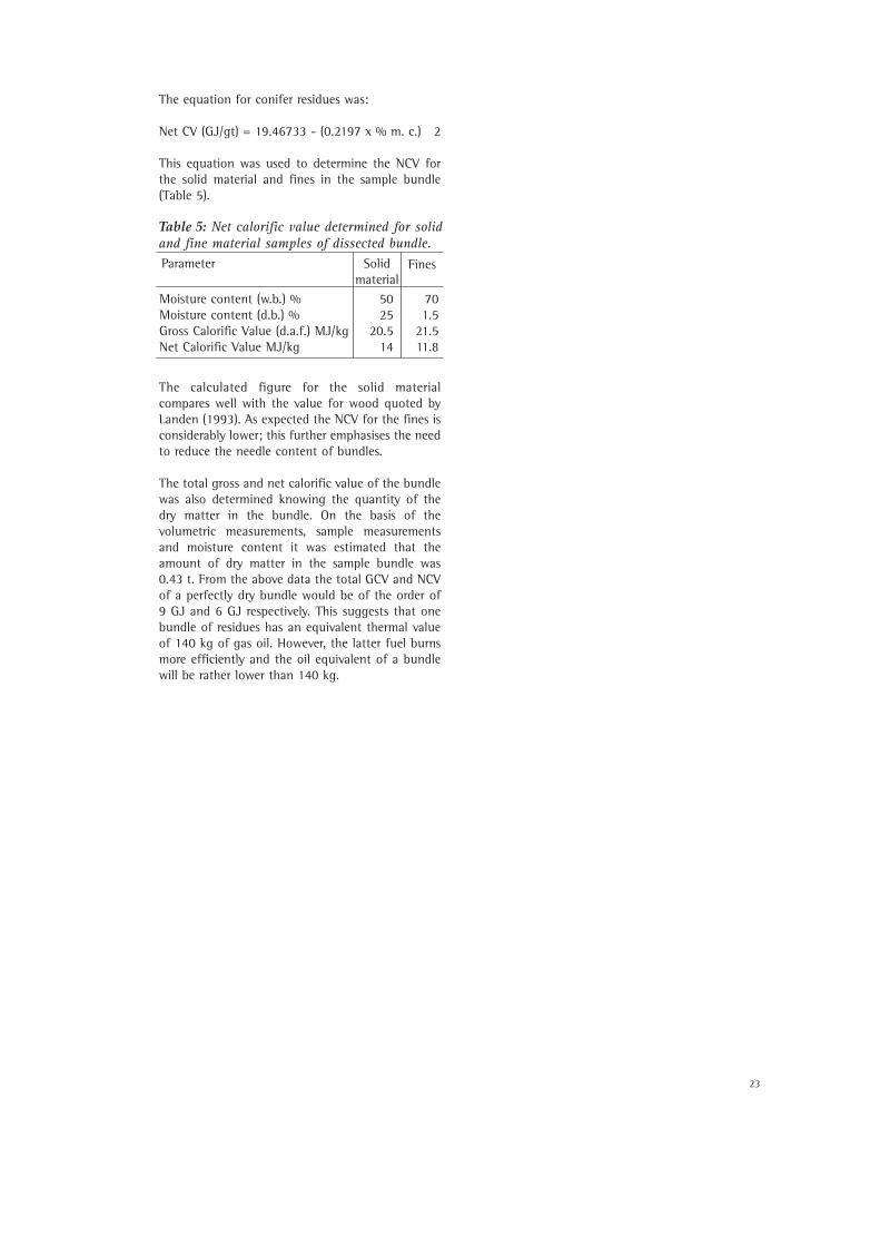
This equation was used to determine the NCV forthe solid material and fines in the sample bundle(Table 5).
The calculated figure for the solid materialcompares well with the value for wood quoted byLanden (1993). As expected the NCV for the fines isconsiderably lower; this further emphasises the needto reduce the needle content of bundles.
The total gross and net calorific value of the bundlewas also determined knowing the quantity of thedry matter in the bundle. On the basis of thevolumetric measurements, sample measurementsand moisture content it was estimated that theamount of dry matter in the sample bundle was0.43 t. From the above data the total GCV and NCVof a perfectly dry bundle would be of the order of 9 GJ and 6 GJ respectively. This suggests that onebundle of residues has an equivalent thermal valueof 140 kg of gas oil. However, the latter fuel burnsmore efficiently and the oil equivalent of a bundlewill be rather lower than 140 kg.
Moisture content (w.b.) % 50 70Moisture content (d.b.) % 25 1.5Gross Calorific Value (d.a.f.) MJ/kg 20.5 21.5Net Calorific Value MJ/kg 14 11.8
Table 5: Net calorific value determined for solidand fine material samples of dissected bundle.Parameter Solid
materialFines
24
25
10. CONCLUSIONS
The work represented a significant contribution tothe experience base and sufficient data have beencollected to enable the design of a commercial,first-generation machine. The compaction of forestresidues is also being developed in Sweden and arefuse baler has been adapted for the production ofbales of forest residues (Hoyne 1996). However, thisBala baler has a very high capital cost and may nothave the flexibility to handle a variety of materials.A commercial bundler could be produced at afraction of the Bala baler cost and could beconsiderably more versatile.
Some first steps were made to determine thepotential markets for forest residues as a fuel whilethe bundles were being stored at the Finsa Ltd.plant. The latter has a large energy demand forchipboard manufacture and an associatedcombustion plant. The company normally uses oil asa primary fuel though waste wood and bark are alsoused. Residue bundles have considerable potentialas a fuel source in such plants. Similar plants couldbe identified as potential users of residues.
Many large bundles were made, stored andtransported with success. The bundling machinefunctioned well and gave an indication of the kindof problems likely to arise in developing acommercial version. Experience was gained instrapping materials and some of the difficulties ofautomating the strapping process were identified. Itwas estimated that less than 1.0 MJ of energy wasconsumed to compact each bundle. This work hascontinued, and the bundles are in open-air storagein stacks, and are being subjected to furtherweathering.
Further stages of development could include:
• design and build cut-off saws for the bundleends;
• add two further rams to achieve highercompaction densities;
• operation on a forwarder more suited to thebundler;
• design of a forwarder rear half integrated with abundler;
• further development of strapping techniques;• experiments with higher compaction densities and
smaller diameter bundles (1.0 m );• a more detailed study of drying rates and moisture
distributions;• a forced air drying study;• bundling of coppice material from short rotation
forestry.
26
REFERENCES
Alexander, J. 1994. Wood Fuel Standards. ETSU Report No. B/W3/00161/REP.
Bala. 1995. Waste Management of the Future. Bala Press AB, Liljegaten 6, S-465 30 Nossebro, Sweden.
Brunberg, B. 1995. Harvesting Logging Residues. In Proceedings of Workshop of IEA/BA Task XII, HarvestingActivity Meeting. Harvesting, storage and drying and road transportation of logging residues.
Buckley, P. 1997. Market Opportunities for Wood Fuel in Ireland. In: Forest Residues in Ireland - Harvesting,Logistics and Markets, COFORD, Dublin.
Bulfin, M. and Rice, B. 1995. Biomass Energy Systems in Ireland. In Proceedings of Workshop on Energy fromBiomass and Wastes.
Carlsson, T., Hansen, R. and Larsson, M. 1980. Trucking of Stumps, Full Trees, Tree Section and LoggingResidues. - Study results 1977–1979.
Department of the Environment and Local Government. 2000. National Climate Change Strategy Ireland. TheStationery Office, Dublin.
ESBI International, 1997. Total Renewable Energy Resource in Ireland. European Union ALTENER ProgrammeContract No. XVII/4.1030/T4/95/IRL. ESBI International, Stephen's Green, Dublin.
Fridley, J. and Burhard, T.H. 1981. Densifying Forest Biomass into Large Round Bales. American Society ofAgricultural Engineers, Paper No 81-1599.
Guimier, D.Y. 1985. Evaluation of Forest Biomass Compaction Systems. Forest Engineering Research Instituteof Canada, Pointe-Claire, Quebec.
Hansen, R. 1978. Hauling of Unlimbed Smallwood. Report No. 1978-09-05, Forskningsstiftelsen, Skogsarbeten,Sweden.
Hoyne, S. 1996. A Study of the Mechanisation of Forest Residue Handling and the Design of a Bundling System.Masters Thesis, University of Limerick.
Jirjis, R. and Lehtikanga P. 1993. Fuel Quality and Dry Matter Loss During Storage of Logging Residues in aWindrow. Report No. 236, Swedish University of Agricultural Sciences, Dept. of Forest Products, Uppsala. ISSN03484599.
Landen, R. 1993. Opportunities for Combustion Systems. In Proceedings Short Rotation Coppice, Growing forProfit. Organised by Royal Agricultural Society of England and Wood Development Group.
Larsson, M. and Norden, B. 1982. Compacting of Tree Sections from Clear Cuttings with Separate Equipment.Report no 1982-10-01. Forskningsstifelsen, Skogsarbeten, Sweden.
Mitchell, C.P., J.B. Hudson, D.N.A. Gardner, P.G.S. Storry and I.M. Gray. 1990. Wood Fuel Supply Strategies.Volume 1. The Report. Harvesting Unit, Dept. of Forestry, University of Aberdeen. ETSU Report No. B 1176-P1.
Mitchell, C.P. and Hankin, C.M. 1993. Forest Residue Harvesting Systems. Wood Supply Research Group,University of Aberdeen.
O’Donnell, B. 1993. Drying and Storage Systems for Short Rotation Forestry. Unpublished PhD Thesis,University College Dublin.