Embed Size (px)
Citation preview
Formentini, Andrea and Trentin, Andrew and Marchesoni, Mario and Zanchetta, Pericle and Wheeler, Patrick (2015) Speed Finite Control Set Model Predictive Control of a PMSM fed by Matrix Converter. IEEE Transactions on Industrial Electronics, 62 (11). pp. 6786-6796. ISSN 0278-0046
Access from the University of Nottingham repository: http://eprints.nottingham.ac.uk/33130/1/Speed%20Finite%20Control%20Set%20Model%20Predictive%20Control%20of%20a%20PMSM%20fed%20by%20Matrix%20Converter.pdf
Copyright and reuse:
The Nottingham ePrints service makes this work by researchers of the University of Nottingham available open access under the following conditions.
· Copyright and all moral rights to the version of the paper presented here belong to
the individual author(s) and/or other copyright owners.
· To the extent reasonable and practicable the material made available in Nottingham
ePrints has been checked for eligibility before being made available.
· Copies of full items can be used for personal research or study, educational, or not-
for-profit purposes without prior permission or charge provided that the authors, title and full bibliographic details are credited, a hyperlink and/or URL is given for the original metadata page and the content is not changed in any way.
· Quotations or similar reproductions must be sufficiently acknowledged.
Please see our full end user licence at: http://eprints.nottingham.ac.uk/end_user_agreement.pdf
A note on versions:
The version presented here may differ from the published version or from the version of record. If you wish to cite this item you are advised to consult the publisher’s version. Please see the repository url above for details on accessing the published version and note that access may require a subscription.
1
Abstract— This paper presents a new speed Finite Control Set
Model Predictive Control (FCS-MPC) algorithm which has been applied to a Permanent Magnet Synchronous Motor (PMSM) driven by a Matrix Converter (MC). This method replaces the classical cascaded control scheme with a single control law that controls the motor currents and speed. Additionally, unlike classical MC modulation methods, the method allows direct control of the MC input currents. The performance of the proposed work has been verified by simulation studies and experimental results.
Index Terms— FCS-MPC, Matrix Converter, PMSM drive
SYMBOLS 詣捗 Input filter inductance 系捗 Input filter capacitance 迎捗 Input filter parasitic resistance 詣鎮 Line inductance 迎鎮 Line resistance 迎陳 Stator resistance 詣陳 Stator inductance 券椎 Pole pairs 砿 Rotor flux 蛍 System inertia 稽銚 Viscous friction 撃鎚 Source voltage 荊鎚 Source current 荊沈珍 jth component of the matrix converter input
current 撃沈珍 jth component of the matrix converter input voltage 荊墜珍 jth component of the matrix converter output current 撃墜珍 jth component of the matrix converter output voltage 荊鳥 Motor direct current 荊槌 Motor quadrature current 降陳 Motor rotor speed 肯追 Motor rotor position 計痛 Motor torque constant
航陳頂 Matrix converter efficiency 糾┘ Updated value 糾┏ Predicted value 恩岫糾岻 Real part
憶岫糾岻 Imaginary part
I. INTRODUCTION
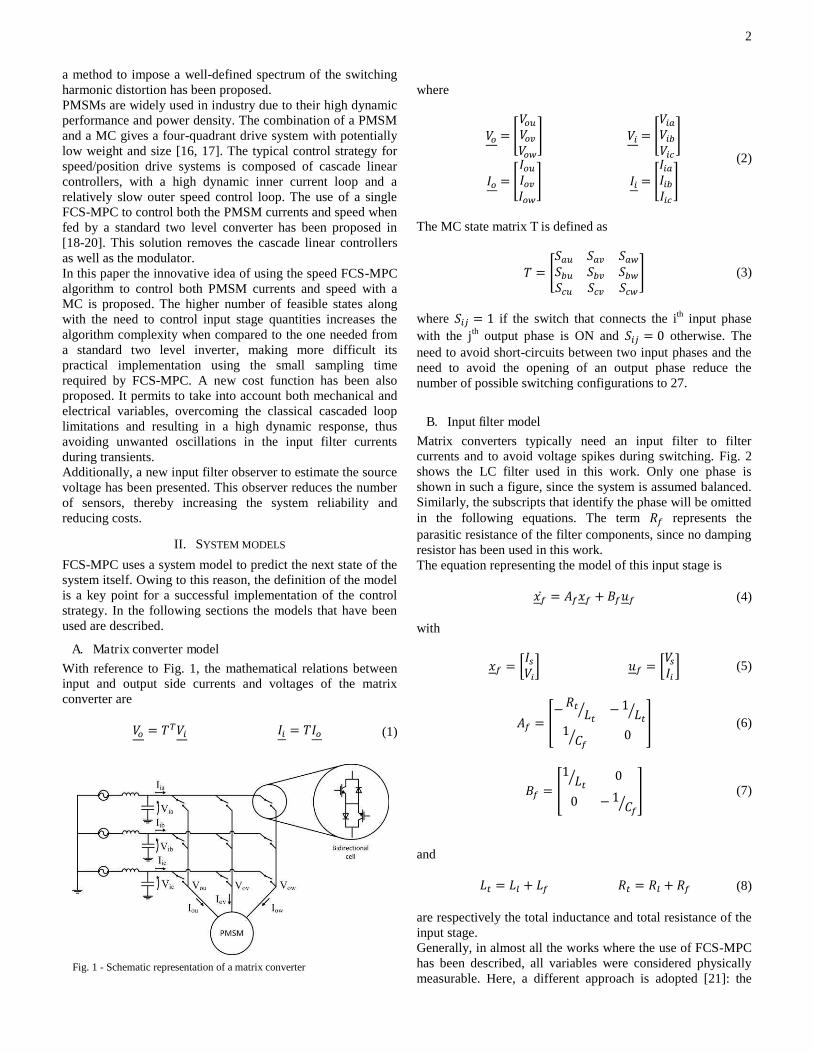
A matrix converter (MC) is a power electronic converter which allows to connect directly two three-phase systems using a matrix of 9 bi-directional switches [1]. Fig. 1 shows a schematic representation of a MC used as a motor drive for a Permanent Magnet Synchronous Motor (PMSM). The MC is composed of a matrix of 9 bidirectional switches which connection between every input and output phase. A single switch can and must be turned on for each converter output leg, in order to avoid both short-circuit of two input phases and opening of an output inductive circuit. This limits the number of possible switching configurations to 27 . One filtering stage is generally present on the input converter side in order to filter the high frequency components introduced by the power semiconductor devices switching. The first modulation strategy for MCs was proposed by Venturini [2]. Subsequently, the space vector modulation (SVM) has been proposed, which is a modulation strategy based on the instantaneous vector representation of the converter input and output voltages [3]. A common drawback related to the above mentioned modulation strategies is the inability to directly control the input filter current, with the consequent risk of creating unstable resonances in the system [4-6]. The two main solutions to this problem, which have been proposed in the technical literature, are the use of a damping resistor in the input filter or the use of a low-pass filter to properly adjust the measurement of the converter input voltage. In recent years, Finite Control Set Model Predictive Control (MPC-FCS) is becoming an interesting and alternative approach to traditional control strategies of power converters [7-10], also owing to the increasing cost reduction of the most powerful control hardware. FCS-MPC uses a model of the system to be controlled to predict the next state of the system itself subjected to each possible control action. The best control action is then chosen by minimizing a cost function. This strategy allows to directly control more than one state variable at the same time, using a single control rule. Several authors have applied FCS-MPC to the MC [11, 12]. In [13] a method for increasing the efficiency of the converter has been proposed, while in [14] the use of a virtual damping resistor to mitigate the resonances of the input filter is proposed. In contrast to SVM modulation, FCS-MPC generates a switching harmonic distortion that is not concentrated on a single frequency, on the contrary its harmonic spectrum is almost white. In some applications this behavior may not be appropriate. Owing to this reason, in [15]
Speed Finite Control Set Model Predictive Control of a PMSM Fed by Matrix Converter Andrea Formentini, Andrew Trentin, Mario Marchesoni, Member, IEEE Pericle Zanchetta, Senior
Member, IEEE and Pat Wheeler, Member, IEEE
2
a method to impose a well-defined spectrum of the switching harmonic distortion has been proposed. PMSMs are widely used in industry due to their high dynamic performance and power density. The combination of a PMSM and a MC gives a four-quadrant drive system with potentially low weight and size [16, 17]. The typical control strategy for speed/position drive systems is composed of cascade linear controllers, with a high dynamic inner current loop and a relatively slow outer speed control loop. The use of a single FCS-MPC to control both the PMSM currents and speed when fed by a standard two level converter has been proposed in [18-20]. This solution removes the cascade linear controllers as well as the modulator. In this paper the innovative idea of using the speed FCS-MPC algorithm to control both PMSM currents and speed with a MC is proposed. The higher number of feasible states along with the need to control input stage quantities increases the algorithm complexity when compared to the one needed from a standard two level inverter, making more difficult its practical implementation using the small sampling time required by FCS-MPC. A new cost function has been also proposed. It permits to take into account both mechanical and electrical variables, overcoming the classical cascaded loop limitations and resulting in a high dynamic response, thus avoiding unwanted oscillations in the input filter currents during transients. Additionally, a new input filter observer to estimate the source voltage has been presented. This observer reduces the number of sensors, thereby increasing the system reliability and reducing costs.
II. SYSTEM MODELS
FCS-MPC uses a system model to predict the next state of the system itself. Owing to this reason, the definition of the model is a key point for a successful implementation of the control strategy. In the following sections the models that have been used are described.
A. Matrix converter model
With reference to Fig. 1, the mathematical relations between input and output side currents and voltages of the matrix converter are 撃墜 噺 劇脹撃沈 荊沈 噺 劇荊墜 (1)
where 撃墜 噺 煩撃墜通撃墜塚撃墜栂晩 撃沈 噺 煩撃沈銚撃沈長撃沈頂 晩
(2) 荊墜 噺 煩荊墜通荊墜塚荊墜栂晩 荊沈 噺 煩荊沈銚荊沈長荊沈頂 晩
The MC state matrix T is defined as 劇 噺 煩鯨銚通 鯨銚塚 鯨銚栂鯨長通 鯨長塚 鯨長栂鯨頂通 鯨頂塚 鯨頂栂 晩 (3)
where 鯨沈珍 噺 な if the switch that connects the ith input phase with the jth output phase is ON and 鯨沈珍 噺 ど otherwise. The need to avoid short-circuits between two input phases and the need to avoid the opening of an output phase reduce the number of possible switching configurations to 27.
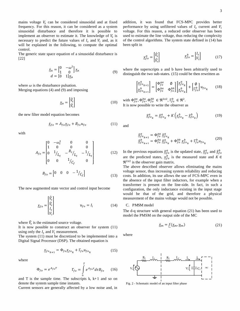
B. Input filter model
Matrix converters typically need an input filter to filter currents and to avoid voltage spikes during switching. Fig. 2 shows the LC filter used in this work. Only one phase is shown in such a figure, since the system is assumed balanced. Similarly, the subscripts that identify the phase will be omitted in the following equations. The term 迎捗 represents the parasitic resistance of the filter components, since no damping resistor has been used in this work. The equation representing the model of this input stage is 捲捗岌 噺 畦捗捲捗 髪 稽捗憲捗 (4) with 捲捗 噺 釆荊鎚撃沈挽 憲捗 噺 釆撃鎚荊沈 挽 (5)
畦捗 噺 崛伐 迎痛 詣痛斑 伐 な 詣痛斑な 系捗斑 ど 崑 (6)
稽捗 噺 崛な 詣痛斑 どど 伐 な 系捗斑 崑 (7)
and 詣痛 噺 詣鎮 髪 詣捗 迎痛 噺 迎鎮 髪 迎捗 (8) are respectively the total inductance and total resistance of the input stage. Generally, in almost all the works where the use of FCS-MPC has been described, all variables were considered physically measurable. Here, a different approach is adopted [21]: the
Fig. 1 - Schematic representation of a matrix converter
3
mains voltage 撃鎚 can be considered sinusoidal and at fixed frequency. For this reason, it can be considered as a system sinusoidal disturbance and therefore it is possible to implement an observer to estimate it. The knowledge of 撃鎚 is necessary to predict the future values of 荊鎚 and 撃沈 and, as it will be explained in the following, to compute the optimal control. The generic state space equation of a sinusoidal disturbance is [22] 捲岌津 噺 峙ど 伐降態な ど 峩 捲津 穴 噺 岷ど な峅捲津
(9)
where 降 is the disturbance pulsation. Merging equations (4) and (9) and imposing 捲津 噺 峪撃侮岌鎚撃侮鎚崋 (10)
the new filter model equation becomes 捲岌捗墜 噺 畦捗墜捲捗墜 髪 稽捗墜憲捗墜 (11) with 畦捗墜 噺 琴欽欽欽
欽欣ど 伐降鎚態 ど どな ど ど どど な 詣痛斑 伐 迎痛 詣痛斑 伐 な 詣痛斑ど ど な 系捗斑 ど 筋禽禽禽禽禁 (12)
稽捗墜 噺 峙ど ど ど 伐 な 系捗斑 峩
(13)
The new augmented state vector and control input become 捲捗墜 噺 琴欽欽欽
欣撃侮岌鎚撃侮鎚荊鎚撃沈筋禽禽禽禁 憲捗墜 噺 荊沈 (14)
where 撃侮鎚 is the estimated source voltage. It is now possible to construct an observer for system (11) using only the 荊鎚 and 撃沈 measurement. The system (11) must be discretized to be implemented into a Digital Signal Processor (DSP). The obtained equation is 捲捗墜賃袋怠 噺 も捗墜捲捗墜賃 髪 ち捗墜憲捗墜賃 (15) where
も捗墜 噺 結凋肉任脹 ち捗墜 噺 豹 結凋肉任邸穴酵稽捗墜脹待 (16)
and T is the sample time. The subscripts k, k+1 and so on denote the system sample time instants. Current sensors are generally affected by a low noise and, in
addition, it was found that FCS-MPC provides better performance by using unfiltered values of 荊鎚 current and 撃沈 voltage. For this reason, a reduced order observer has been used to estimate the line voltage, thus reducing the complexity of the control algorithms. The system state defined in (14) has been split in 捲捗墜銚 噺 峪撃侮岌鎚撃侮鎚崋 捲捗墜長 噺 釆荊鎚撃沈挽 (17)
where the superscripts a and b have been arbitrarily used to distinguish the two sub-states. (15) could be then rewritten as 煩捲捗墜銚 賃袋怠捲捗墜長 賃袋怠晩 噺 峪も捗墜銚銚 叶も捗墜長銚 も捗墜長長崋 煩捲捗墜銚 賃捲捗墜長 賃晩 髪 釆 叶ち捗墜長 挽 憲捗墜賃 (18)
with も捗墜銚銚 ┸ も捗墜長銚┸ も捗墜長長 樺 恩態掴態, ち捗墜長 樺 恩態. It is now possible to write the observer as 捲葡捗墜銚 賃 噺 捲賦捗墜銚 賃 髪 計 岾捲捗墜長 賃 伐 捲賦捗墜長 賃峇 (19)
and 捲賦捗墜銚 賃袋怠 噺 も捗墜銚銚 捲葡捗墜銚 賃 捲賦捗墜長 賃袋怠 噺 も捗墜長銚 捲葡捗墜銚 賃 髪 も捗墜長長 捲捗墜長 賃 髪 ち捗墜長 憲捗墜賃
(20)
In the previous equations 捲葡捗墜銚 is the updated state, 捲賦捗墜銚 and 捲賦捗墜長 are the predicted states, 捲捗墜長 is the measured state and 計 樺恩態掴態 is the observer gain matrix. The above described observer allows eliminating the mains voltage sensor, thus increasing system reliability and reducing costs. In addition, its use allows the use of FCS-MPC even in the absence of the input filter inductors, for example when a transformer is present on the line-side. In fact, in such a configuration, the only inductance existing in the input stage would be that of the grid, and therefore a physical measurement of the mains voltage would not be possible.
C. PMSM model
The d-q structure with general equation (21) has been used to model the PMSM on the output side of the MC 捲岌陳 噺 血岫捲陳┸ 憲陳岻 (21) where
Fig. 2 - Schematic model of an input filter phase
4
捲陳 噺 頒 荊鳥荊槌降追肯追 番 憲陳 噺 崛撃鳥撃槌劇挑 崑 (22)
and
血岫糾岻 噺均勤勤勤勤僅 伐 迎陳詣陳 荊鳥 髪 券椎荊槌降追 髪 撃鳥詣陳伐券椎荊鳥降追 伐 迎陳詣陳 荊槌 伐 砿券椎詣陳 降追 髪 撃槌詣陳ぬ砿券椎に蛍 荊槌 伐 稽銚蛍 降追 伐 劇挑蛍降追 斤錦
錦錦錦巾
(23)
The absence of an integral stage in the FCS-MPC imposes to observe a possible torque disturbance (劇挑 in (23)) applied to the motor shaft in order to eliminate the steady state speed error. Including a constant disturbance observer the system (21) becomes 捲岌陳墜 噺 血陳墜岫捲陳墜 ┸ 憲陳墜岻 (24) where
捲 噺 琴欽欽欽欣 荊鳥荊槌降追肯追劇侮挑 筋禽禽
禽禁 憲 噺 釆撃鳥撃槌 挽 (25)
and
血陳墜岫糾岻 噺均勤勤勤勤勤僅 伐 迎陳詣陳 荊鳥 髪 券椎荊槌降追 髪 撃鳥詣陳伐券椎荊鳥降追 伐 迎陳詣陳 荊槌 伐 砿券椎詣陳 降追 髪 撃槌詣陳ぬ砿券椎に蛍 荊槌 伐 稽銚蛍 降追 伐 劇侮挑蛍降追ど 斤錦
錦錦錦錦巾
(26)
The system (24) has been discretized using a Taylor series expansion [23] and a truncation order of 1. Considering that the measures of both 荊鳥 and 荊槌 are available and using only the shaft position to update the estimated state, it is possible to implement a linear reduced order observer for the mechanical subspace only. Its equations are 捲葡陳墜長 賃 噺 捲賦陳墜長 賃 髪 詣 ゲ 系 岾捲陳墜長 賃 伐 捲賦陳墜長 賃峇 (27)
and 捲賦陳墜銚 賃袋怠 噺 血帖銚 岾捲陳墜銚 賃 ┸ 捲葡陳墜長 賃峇 髪 稽帖銚 憲賃 捲賦陳墜長 賃袋怠 噺 畦帖長銚 捲陳墜銚 賃 髪 畦帖長長 捲葡陳墜長 賃
(28) (29)
where 畦経決欠 噺 頒ぬ砿券喧劇嫌に蛍 どど どど ど番 畦帖長長 噺 琴欽欽欽
欣な 伐 稽欠劇鎚蛍 ど ど劇鎚 な どど ど な筋禽禽禽禁
(30) 稽帖銚 噺 頒 劇嫌詣陳 どど 劇嫌詣陳番 系 噺 岷ど な ど峅
捲陳墜銚 噺 釆荊鳥荊槌挽 捲陳墜長 噺 煩降追肯追劇侮挑 晩 (31)
詣 樺 恩戴掴怠 is the observer gain matrix and the subscript D denotes discretized quantities. Note that the prediction equation (28) is not necessary for the observer, but it will be used later on by the predictive algorithm.
III. FINITE CONTROL SET MODEL PREDICTIVE CONTROL
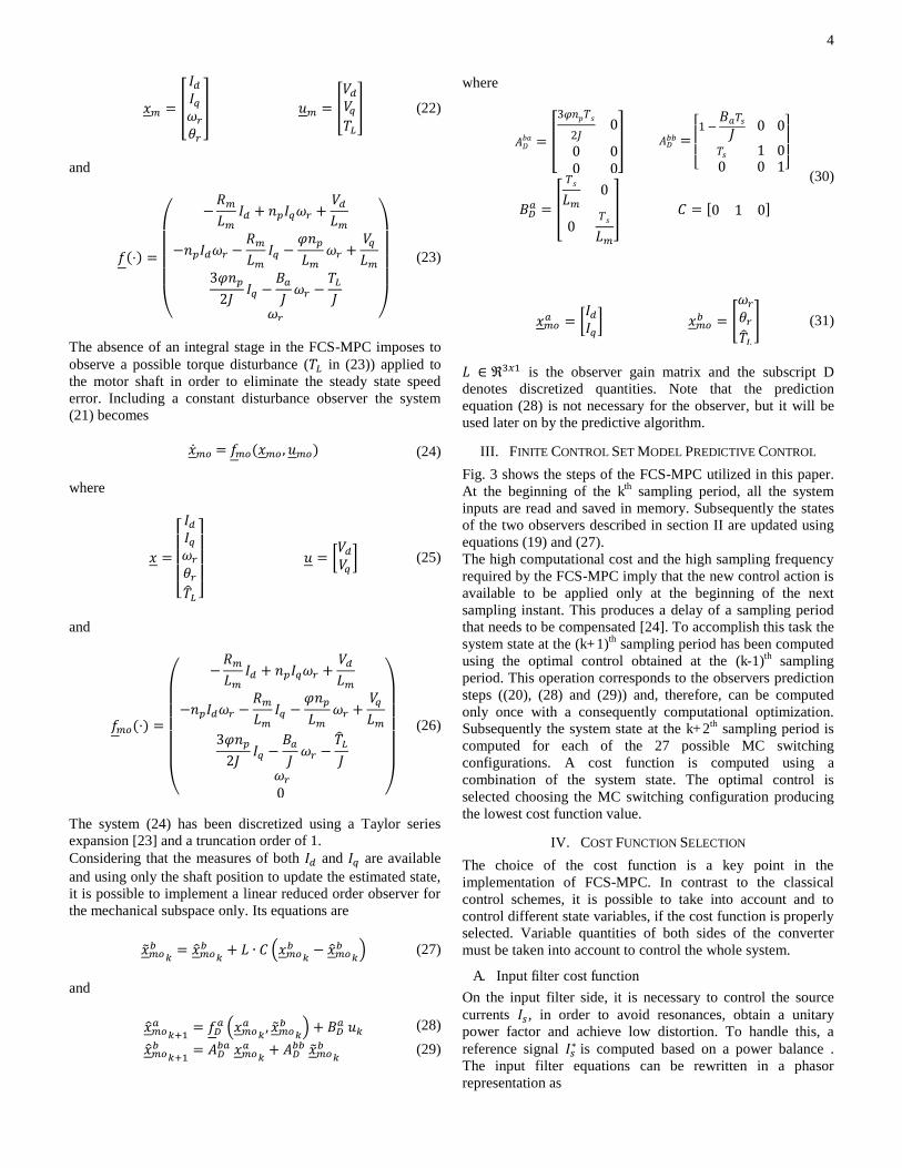
Fig. 3 shows the steps of the FCS-MPC utilized in this paper. At the beginning of the kth sampling period, all the system inputs are read and saved in memory. Subsequently the states of the two observers described in section II are updated using equations (19) and (27). The high computational cost and the high sampling frequency required by the FCS-MPC imply that the new control action is available to be applied only at the beginning of the next sampling instant. This produces a delay of a sampling period that needs to be compensated [24]. To accomplish this task the system state at the (k+1)th sampling period has been computed using the optimal control obtained at the (k-1)th sampling period. This operation corresponds to the observers prediction steps ((20), (28) and (29)) and, therefore, can be computed only once with a consequently computational optimization. Subsequently the system state at the k+2th sampling period is computed for each of the 27 possible MC switching configurations. A cost function is computed using a combination of the system state. The optimal control is selected choosing the MC switching configuration producing the lowest cost function value.
IV. COST FUNCTION SELECTION
The choice of the cost function is a key point in the implementation of FCS-MPC. In contrast to the classical control schemes, it is possible to take into account and to control different state variables, if the cost function is properly selected. Variable quantities of both sides of the converter must be taken into account to control the whole system.
A. Input filter cost function
On the input filter side, it is necessary to control the source currents 荊鎚, in order to avoid resonances, obtain a unitary power factor and achieve low distortion. To handle this, a reference signal 荊鎚茅 is computed based on a power balance . The input filter equations can be rewritten in a phasor representation as
5
薩沈 噺 盤な 伐 系捗詣痛降鎚態 髪 系捗迎痛倹降鎚匪薩鎚 伐 惨鎚系捗倹降鎚 惨沈 噺 岫伐迎痛 伐 詣痛倹降鎚岻薩鎚 髪 惨鎚
(32)
The power at the input side of the MC is 鶏沈 噺 ぬに 盤恩岫薩沈岻恩岫惨沈岻 髪 憶岫薩沈岻憶岫惨沈岻匪 (33)
Substituting (32) in (33) 鶏沈 噺 ぬに 岫恩岫薩鎚岻恩岫惨鎚岻 髪 憶岫薩鎚岻憶岫惨鎚岻 伐 迎痛荊 違鎚態岻 (34)
and, assuming a unitary power factor on the grid side 鶏沈 噺 ぬに 岫荊 違鎚撃博鎚 伐 迎痛荊 違鎚態岻 (35)
where superscripts 糾 違 denote modules. On the output side of the converter the power can be written as 鶏墜 噺 ぬに 盤迎陳荊槌態匪 髪 計痛降追荊槌 (36)
In (36) 荊鳥 is considered negligible and the motor iron losses are neglected. Input and output MC power can be related by the efficiency of the converter. In motoring mode the relation is 鶏墜 噺 考陳頂鶏沈 (37) The reference source current module has been finally calculated replacing (35) and (36) in (37) and solving for 荊 違鎚
荊 違鎚茅 噺 撃博鎚に迎痛 罰 ヂつぬ迎痛 つ 噺 な考陳頂 盤伐ひ迎痛迎陳荊槌態 伐 は計痛降追荊槌迎痛匪 髪 ひ撃博鎚態ね
(38)
In regenerative mode (37) becomes 鶏墜 噺 鶏沈考陳頂 (39)
and consequently 荊 違鎚茅 噺 撃博鎚に迎痛 罰 ヂつぬ迎痛 つ 噺 考陳頂盤伐ひ迎痛迎陳荊槌態 伐 は計痛降追荊槌迎痛匪 髪 ひ撃博鎚態ね
(40)
The proposed method of current reference generation is correct if referred to electrical steady-state. However, the electric variables transient is very fast and it has been verified experimentally that the use of the proposed method also during transients does not affect so much the system performance. Using eqs. (38) and (40) and imposing 薩鎚茅 in phase with 惨鎚, the CF relative to the input filter at the kth sample time has been defined as 潔沈捗 噺 岾荊鎚茅底 伐 荊鎚底賃袋態峇態 髪 岾荊鎚茅庭 伐 荊鎚庭 賃袋態峇態
(41)
where the subscripts 糠 and 紅 denote quantities transformed in the 糠 伐 紅 domain. This cost function ensures a sinusoidal input current and a unity power factor. The use of sinusoidal references, compared to reactive power minimization method used in some other works[13], avoids that the system becomes unstable owing to resonances due to the input filter, even in the presence of a low damping, without affecting the dynamic performance of the system. The presence of the 潔沈捗 term slightly reduces the performance on the motor side. It is however necessary to have a stable behavior on the matrix converter input side.
B. PMSM cost function
The main variable to control on the PMSM side is the motor speed. Also in this case the square error has been used and the speed cost function term at the kth sample time has been defined as 潔摘 噺 結摘態 賃袋態 (42) with 結摘賃袋態 噺 降追茅 伐 降追賃袋態 (43) The same equation (28) and (29) used for the observer prediction step has been adopted to predict the future states of the motor variables. It has been however necessary to
Update
observer states
Delay
compensation
Predict using
the i th controlWrite outputs
Compute cost
functionsi=27
i=i+1
Select control
with minimum
cost function
Read inputs
Y
N
Fig. 3 – FCS-MPC flowchart.
6
discretize the 3rd equation of (26) with a Taylor series truncated at the second term in order to obtain a direct relation between 降追賃袋怠 and input 憲賃. The first equation of (29) then becomes 降追賃袋怠 噺 紘怠荊鳥賃降追賃 髪 紘態荊槌賃 髪 紘戴降追賃 髪 紘替劇侮挑賃 髪 紘泰撃槌賃 (44) where 紘怠 噺 伐 ぬ砿劇鎚態券椎態ね蛍
紘態 噺 ぬ砿劇鎚券椎に蛍 伐 ぬ劇鎚態砿券椎 磐ぬ稽銚に蛍態 髪 迎陳に蛍詣陳卑に
紘戴 噺 な 伐 ぬ劇鎚稽銚蛍 髪 劇鎚態 峭稽銚態蛍態 伐 ぬ券椎態砿態に蛍詣陳 嶌に 紘替 噺 劇鎚態稽銚に蛍態 伐 劇鎚蛍 紘泰 噺 ぬ砿劇鎚態券椎ね蛍詣陳
(45)
In addition to the motor speed it is also important to control the motor currents in order to reduce the output currents distortion during steady-state operation and to avoid exceeding the drive and motor physical limits during transients. For these reasons, a 荊槌 current reference has been defined as 荊槌茅 噺 盤稽銚降追茅 伐 劇侮挑匪計痛貸怠 (46) and used in the current cost function
潔沈鳥 噺 荊鳥態賃袋態 潔沈槌 噺 岾荊槌茅 伐 荊槌賃袋態峇態 (47)
These terms ensure good currents quality during steady-state operation. An additional term has been added to avoid currents exceeding the limits during transients 潔沈鎮 噺 犯な結など┸ 荊 違墜 伴 荊墜陳銚掴ど┸ 荊 違墜 隼 荊墜陳銚掴 (48)
where 荊墜陳銚掴 is the maximum module of the motor currents. The total cost function has been created as a weighted sum of the single CFs as 潔 噺 拳摘潔摘 髪 拳沈捗潔沈捗 髪 拳沈鳥潔沈鳥 髪 拳沈槌潔沈槌 髪 潔沈鎮 (49)
C. Weight parameters tuning
FCS-MPC is a very versatile control strategy able to control different variables at the same time by simply adding appropriate terms to the cost function. However, as the number of terms in the cost function increases, the adjustment of the weight parameters can become very complex. This problem is still an open topic in literature. Different solutions have been thoroughly analyzed and several approaches have been proposed [25-29].
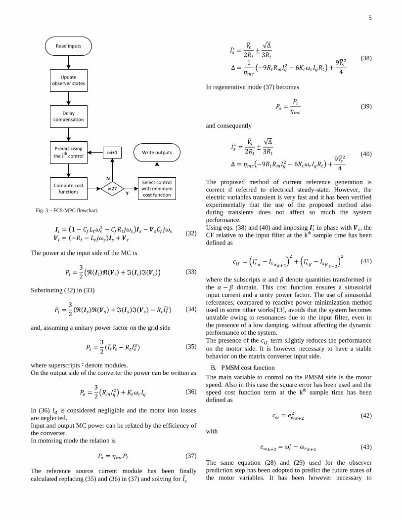
In this work, to properly tune the weights in (49), the system has been initially simulated in a speed steady-state condition (50 rad/s) using a Simulink model. As shown in [16], the total harmonic distortion (THD) of the input and output currents are affected not only by the weight parameters but also by the output current amplitude and output power magnitude. The system has been therefore analyzed in different working points: 拳沈捗 has been arbitraril y set equal to 1 and the value of 拳沈鳥 and 拳沈槌 have been selected in order to have low input and output THDs in the whole operating range. Subsequently, the dynamic response to a speed reference variation has been analyzed. To obtain a good speed dynamic response, 拳摘 should be set to a high value. However, the predominance of the 潔摘 term on the current ones does not permit to properly control currents during speed transients, resulting in distorted waveforms and unstable oscillatory behaviors as shown in Fig. 4. To handle this problem, the absolute value of the speed tracking error in (43) has been limited modifying the speed reference as 降蕪追茅噺 崔結摘陳銚掴 髪 降追賃袋怠┸ 降追茅 伐 降追賃袋怠 伴 結摘陳銚掴降追賃袋怠 伐 結摘陳銚掴 ┸ 降追茅 伐 降追賃袋怠 隼 伐結摘陳銚掴降追茅┸ 剣建月結堅拳件嫌結
(50)
(43) has been accordingly modified as 結摘賃袋態 噺 降蕪追茅 伐 降追賃袋態 (51)
Fig. 4 – Simulative response to a reference step variation without the limitation of equation (50).
0.05 0.1 0.15 0.2 0.25 0.3 0.35 0.4 0.45 0.5
0
20
40
r [
rad/
s]
0.05 0.1 0.15 0.2 0.25 0.3 0.35 0.4 0.45 0.5-20
0
20
I od,
I oq [
A]
0.05 0.1 0.15 0.2 0.25 0.3 0.35 0.4 0.45 0.5-20
0
20
Time [s]
I s [A
]
7
During speed transients the product 拳摘結摘陳銚掴 defines the importance of the speed term over the current ones: a too small value compromises the speed dynamic response, while a too high value affects the current THDs. Also in this case, a
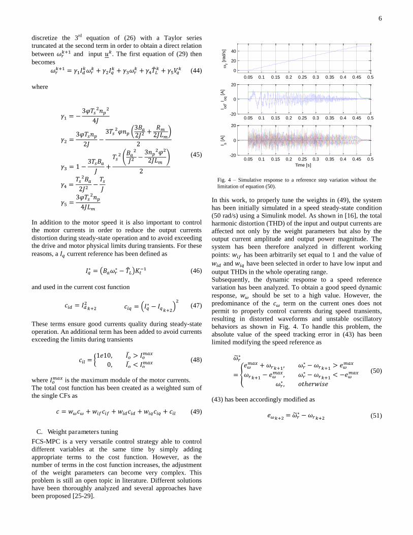
simulative analysis has been used to tune this term in order to ensure a good currents control during speed transients, while maintaining a good speed dynamic response. Fig. 5 shows the system response with different value of 結摘陳銚掴 keeping constant the others parameters. The value of 拳摘 has been subsequently tuned keeping constant the above mentioned product. High values of 拳摘 increase the speed dynamic response but decrease currents quality in steady-state due to the position transducer noise. Fig. 6 shows the system response with different values of 拳摘, keeping constant the product 拳摘結摘陳銚掴 and the others weights. The weight parameters resulting from the described procedure have been finally normalized and are reported in Table I. The influence of weight parameters variation has been also tested, resulting in a good system robustness within a variation of 罰などガ.
D. Robustness analysis
In industrial applications the identified system parameters may be slightly wrong or change in time. The most critical are usually the mechanical ones as they are dependent from the application. For this reason, it is important to evaluate the control system robustness to parameters variation. To this end, a simulative model of the experimental system described in the next section has been implemented. Subsequently the motor inertia and friction have been changed and the system response has been analyzed. Fig. 7 shows the system response to a speed reference change with different inertia values. It can be noted that the system is stable and it exhibits good performance even with a 20% inertia variation. Similarly, a speed reference step variation is depicted in Fig. 8, with different friction values. Also in this case, the traces show good system stability against wrong friction values.
TABLE I NORMALIZED COST FUNCTION WEIGHTS
Parameter Value Units 拳摘 1 - 拳沈捗 4e-5 拳沈鳥 4e-5 - 拳沈槌 1e-5 - 荊墜陳銚掴 10 A 結摘陳銚掴 1 堅欠穴 糾 嫌貸怠
Fig. 6 – Simulative response to a speed reference step variation with different 拳摘 value (keeping constant the product 拳摘結摘陳銚掴). Blue: nominal value (Table I). Red: 25% of nominal value. Green: 400% of nominal value.
0 0.1 0.2 0.3 0.4 0.5 0.6
0
20
40
r [
rad/
s]
0 0.1 0.2 0.3 0.4 0.5 0.6
-5
0
5
10
Time [s]
I oq [
A]
Fig. 5 – Simulative response to a speed reference step variation with different 結摘陳銚掴 value. Blue: nominal value (Table I). Red: 200% of nominal value. Green: 400% of nominal value.
0.1 0.2 0.3 0.4 0.50
20
40
r [
rad/
s]
0.1 0.2 0.3 0.4 0.50
5
10
I oq [
A]
0.1 0.2 0.3 0.4 0.5-5
0
5
I od [
A]
Time [s]
Fig. 7 – Simulative response to a speed reference step variation with different inertia values. Blue: nominal inertia. Red: 120% of nominal inertia. Green: 80% of nominal inertia.
0 0.1 0.2 0.3 0.4 0.5 0.6 0.70
20
40
60
Spe
ed [
rad/
s]
0 0.1 0.2 0.3 0.4 0.5 0.6 0.7-5
0
5
10
15
Time [s]
Mot
or I q [
A]
8
V. EXPERIMENTAL RESULTS
The proposed control algorithm has been tested on an experimental set-up. Fig. 9 shows the controller and matrix converter used. The proposed control algorithm has been implemented on a Texas Instruments DSP C6713 with a sample time of にど 航嫌. An FPGA has been connected with the
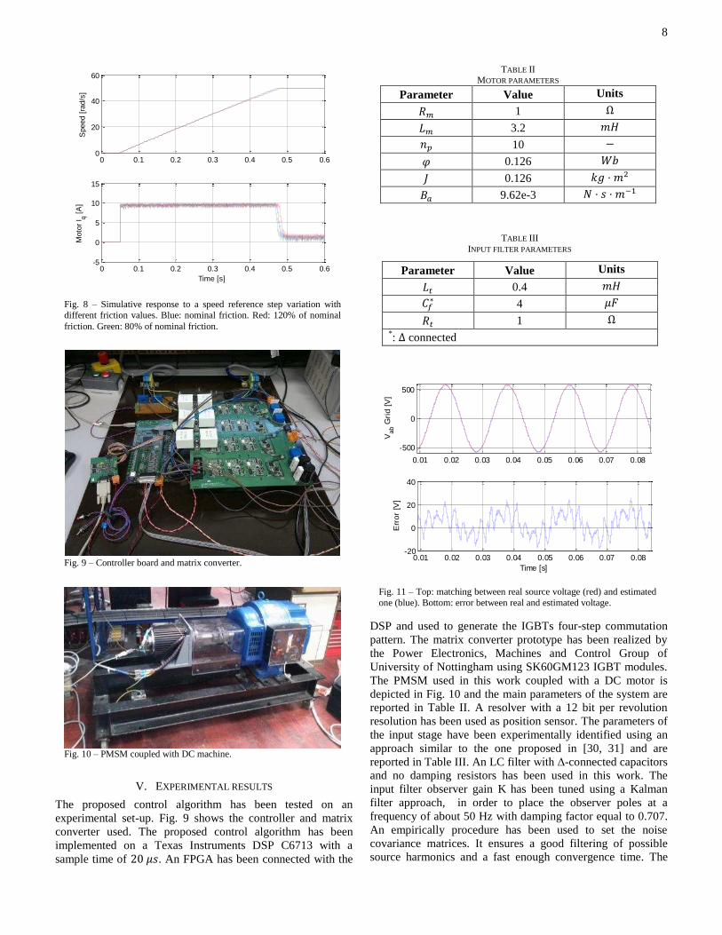
DSP and used to generate the IGBTs four-step commutation pattern. The matrix converter prototype has been realized by the Power Electronics, Machines and Control Group of University of Nottingham using SK60GM123 IGBT modules. The PMSM used in this work coupled with a DC motor is depicted in Fig. 10 and the main parameters of the system are reported in Table II . A resolver with a 12 bit per revolution resolution has been used as position sensor. The parameters of the input stage have been experimentally identified using an approach similar to the one proposed in [30, 31] and are reported in Table III. An LC filter with 〉-connected capacitors and no damping resistors has been used in this work. The input filter observer gain K has been tuned using a Kalman filter approach, in order to place the observer poles at a frequency of about 50 Hz with damping factor equal to 0.707. An empirically procedure has been used to set the noise covariance matrices. It ensures a good filtering of possible source harmonics and a fast enough convergence time. The
TABLE III INPUT FILTER PARAMETERS
Parameter Value Units 詣痛 0.4 兼茎 系捗茅 4 航繋 迎痛 1 よ *: つ connected
Fig. 9 – Controller board and matrix converter.
Fig. 10 – PMSM coupled with DC machine.
Fig. 8 – Simulative response to a speed reference step variation with different friction values. Blue: nominal friction. Red: 120% of nominal friction. Green: 80% of nominal friction.
0 0.1 0.2 0.3 0.4 0.5 0.60
20
40
60S
peed
[ra
d/s]
0 0.1 0.2 0.3 0.4 0.5 0.6-5
0
5
10
15
Time [s]
Mot
or I q [
A]
TABLE II MOTOR PARAMETERS
Parameter Value Units 迎陳 1 よ 詣陳 3.2 兼茎 券椎 10 伐 砿 0.126 激決 蛍 0.126 倦訣 糾 兼態 稽銚 9.62e-3 軽 糾 嫌 糾 兼貸怠
Fig. 11 – Top: matching between real source voltage (red) and estimated one (blue). Bottom: error between real and estimated voltage.
0.01 0.02 0.03 0.04 0.05 0.06 0.07 0.08
-500
0
500V
ab G
rid
[V]
0.01 0.02 0.03 0.04 0.05 0.06 0.07 0.08-20
0
20
40
Time [s]
Err
or [V
]
9
comparison between the measured line-to-line source voltage and the estimated one is reported in Fig. 11, where a very good match between the two quantities can be noted. The motor-side observer has been empirically tuned to handle the system mechanical resonances: a pole placement approach
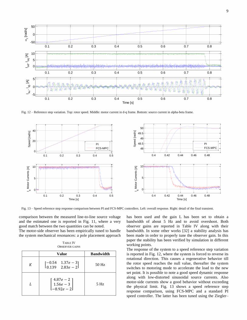
has been used and the gain L has been set to obtain a bandwidth of about 5 Hz and to avoid overshoot. Both observer gains are reported in Table IV along with their bandwidth. In some other works [32] a stability analysis has been made in order to properly tune the observer gain. In this paper the stability has been verified by simulation in different working points. The response of the system to a speed reference step variation is reported in Fig. 12, where the system is forced to reverse its rotational direction. This causes a regenerative behavior till the rotor speed reaches the null value, thereafter the system switches to motoring mode to accelerate the load to the new set point. It is possible to note a good speed dynamic response along with low-distorted sinusoidal source currents. Also motor-side currents show a good behavior without exceeding the physical limit. Fig. 13 shows a speed reference step response comparison, using FCS-MPC and a standard PI speed controller. The latter has been tuned using the Ziegler–
Fig. 12 – Reference step variation. Top: rotor speed. Middle: motor current in d-q frame. Bottom: source current in alpha-beta frame.
0.1 0.2 0.3 0.4 0.5 0.6 0.7 0.8-50
0
50
r [rad
/s]
0.1 0.2 0.3 0.4 0.5 0.6 0.7 0.8
0
5
10
I od,
I oq [A
]
0.1 0.2 0.3 0.4 0.5 0.6 0.7 0.8-5
0
5
Time [s]
I s ,
I s [A
]
Fig. 13 – Speed reference step response comparison between PI and FCS-MPC controllers. Left: overall response. Right: detail of the final transient.
0.1 0.2 0.3 0.4 0.5
0
20
40
Spe
ed [
rad/
s]
0.1 0.2 0.3 0.4 0.5
0
5
10
I q Mot
or C
urre
nts
[A]
Time [s]
PI
FCS-MPC
0.4 0.42 0.44 0.46 0.48
48
48.5
49
49.5
50
Spe
ed [
rad/
s]
0.4 0.42 0.44 0.46 0.48
0
5
10
I q Mot
or C
urre
nts
[A]
Time [s]
PI
FCS-MPC
TABLE IV OBSERVER GAINS
Value Bandwidth 計 峙伐ど┻のね な┻ぬば結 伐 ぬど┻なぬひ に┻ぱぬ結 伐 に峩 50 Hz
詣 煩 ね┻ぱば結 伐 にな┻のは結 伐 ぬ伐ぱ┻ひに結 伐 に晩 5 Hz
10
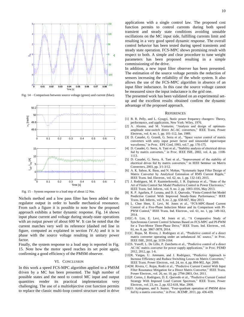
Nichols method and a low pass filter has been added to the regulator output in order to handle mechanical resonance. From such a figure it is possible to note how the proposed approach exhibits a better dynamic response. Fig. 14 shows input phase current and voltage during steady-state operations with an output power of about 600 W. It can be noted that the current matches very well its reference (dashed red line in figure, computed as explained in section IV.A) and it is in phase with the source voltage resulting in unitary power factor. Finally, the system response to a load step is reported in Fig. 15. Note how the motor speed reaches its set point again, confirming a good efficiency of the PMSM observer.
VI. CONCLUSION
In this work a speed FCS-MPC algorithm applied to a PMSM driven by a MC has been presented. The high number of possible states and the need to control MC input and output quantities render its practical implementation very challenging. The use of a multiobjective cost function permits to replace the classic multi-loop control structure used in drive
applications with a single control law. The proposed cost function permits to control currents during both speed transient and steady state conditions avoiding unstable oscillations on the MC input side, fulfilling currents limit and resulting in a very good speed dynamic response. The overall control behavior has been tested during speed transients and steady state operation. FCS-MPC shows promising result with respect to both. A simple and clear procedure to tune weight parameters has been proposed resulting in a simple commissioning of the drive. In addition, a new input filter observer has been presented. The estimation of the source voltage permits the reduction of sensors increasing the reliability of the whole system. It also allows the use of the FCS-MPC algorithm in absence of an input filter inductance. In this case the source voltage cannot be measured since the input inductance is the grid one. The presented work has been validated on an experimental set-up and the excellent results obtained confirm the dynamic advantage of the proposed approach.
REFERENCES [1] B. R. Pelly, and L. Gyugyi, Static power frequency changers: Theory,
performance, and application, New York: Wiley, 1976. [2] A. Alesina, and M. Venturini, “Analysis and design of optimum-
amplitude nine-switch direct AC-AC converters,” IEEE Trans. Power Electron., vol. 4, no. 1, pp. 101-112, Jan. 1989.
[3] D. Casadei, G. Grandi, G. Serra et al., “Space vector control of matrix converters with unity input power factor and sinusoidal input/output waveforms,” in Proc. EPE Conf, 1993, vol.7, pp. 170-175.
[4] D. Casadei, G. Serra, A. Tani et al., “Stability analysis of electrical drives fed by matrix converters,” in Proc. IEEE ISIE, 2002, vol. 4, pp. 1108-1113.
[5] D. Casadei, G. Serra, A. Tani et al., “Improvement of the stability of electrical drives fed by matrix converters,” in IEEE Seminar on Matrix Converters, 2003, pp. 3/1-3/12.
[6] A. K. Sahoo, K. Basu, and N. Mohan, “Systematic Input Filter Design of Matrix Converter by Analytical Estimation of RMS Current Ripple,” IEEE Trans. Ind. Electron., vol. 62, no. 1, pp. 132-143, 2015.
[7] J. Rodriguez, M. P. Kazmierkowski, J. R. Espinoza et al., “State of the Art of Finite Control Set Model Predictive Control in Power Electronics,” IEEE Trans. Ind. Inform., vol. 9, no. 2, pp. 1003-1016, May 2013.
[8] R. P. Aguilera, P. Lezana, and D. E. Quevedo, “Finite-Control-Set Model Predictive Control With Improved Steady-State Performance,” IEEE Trans. Ind. Inform., vol. 9, no. 2, pp. 658-667, May 2013.
[9] L. Chee Shen, E. Levi, M. Jones et al., “FCS-MPC-Based Current Control of a Five-Phase Induction Motor and its Comparison with PI-PWM Control,” IEEE Trans. Ind. Electron., vol. 61, no. 1, pp. 149-163, 2014.
[10] C.-S. Lim, E. Levi, M. Jones et al., “A Comparative Study of Synchronous Current Control Schemes Based on FCS-MPC and PI-PWM for a Two-Motor Three-Phase Drive,” IEEE Trans. Ind. Electron., vol. 61, no. 8, pp. 3867-3878, 2014.
[11] C. Rojas, M. Rivera, J. Rodriguez et al., “Predictive control of a direct matrix converter operating under an unbalanced AC source,” in Proc. IEEE ISIE, 2010, pp. 3159-3164.
[12] S. Yusoff, L. De Lillo, P. Zanchetta et al., “Predictive control of a direct AC/AC matrix converter for power supply applications,” in Proc. PEMD 2012, 2012, pp. 1-6.
[13] R. Vargas, U. Ammann, and J. Rodriguez, “Predictive Approach to Increase Efficiency and Reduce Switching Losses on Matrix Converters,” IEEE Trans. Power Electron., vol. 24, no. 4, pp. 894-902, Apr. 2009.
[14] M. Rivera, C. Rojas, Rodri et al., “Predictive Current Control With Input Filter Resonance Mitigation for a Direct Matrix Converter,” IEEE Trans. Power Electron., vol. 26, no. 10, pp. 2794-2803, Oct. 2011.
[15] P. Cortes, J. Rodriguez, D. E. Quevedo et al., “Predictive Current Control Strategy With Imposed Load Current Spectrum,” IEEE Trans. Power Electron., vol. 23, no. 2, pp. 612-618, Mar. 2008.
[16] O. Aydogmus, and S. Sunter, “Four-quadrant operation of PMSM drive fed by a matrix converter,” in Proc. ACEMP, 2011, pp. 436-439.
Fig. 14 – Comparison between source voltage (green) and current (blue).
0 0.01 0.02 0.03 0.04 0.05 0.06 0.07 0.08-6
-4
-2
0
2
4
6
Time [s]
I s,
0 0.01 0.02 0.03 0.04 0.05 0.06 0.07 0.08-150
-100
-50
0
50
100
150
V̂s,
Fig. 15 – System response to a load step of about 12 Nm.
0 0.1 0.2 0.3 0.4 0.5 0.6 0.
49.6
49.8
50
50.2
r [
rad/
s]
0 0.1 0.2 0.3 0.4 0.5 0.6 0.-5
0
5
10
15
I od,
I oq [
A]
Time [s]

11
[17] X. Changliang, Z. Jiaxin, Y. Yan et al., “A Novel Direct Torque Control of Matrix Converter-Fed PMSM Drives Using Duty Cycle Control for Torque Ripple Reduction,” IEEE Trans. Ind. Electron., vol. 61, no. 6, pp. 2700-2713, 2014.
[18] E. J. Fuentes, C. A. Silva, and J. I. Yuz, “Predictive Speed Control of a Two-Mass System Driven by a Permanent Magnet Synchronous Motor,” IEEE Trans. Ind. Electron., vol. 59, no. 7, pp. 2840-2848, Jul. 2012.
[19] M. Preindl, and S. Bolognani, “Model Predictive Direct Speed Control with Finite Control Set of PMSM Drive Systems,” IEEE Trans. Power Electron., vol. 28, no. 2, pp. 1007-1015, Feb. 2013.
[20] E. Fuentes, D. Kalise, J. Rodriguez et al., “Cascade-Free Predictive Speed Control for Electrical Drives,” IEEE Trans. Ind. Electron., vol. 61, no. 5, pp. 2176-2184, 2014.
[21] A. Formentini, L. de Lillo, M. Marchesoni et al., “A new mains voltage observer for PMSM drives fed by matrix converters,” in Proc. EPE'14-ECCE Europe, 2014, pp. 1-10.
[22] G. F. Franklin, M. L. Workman, and D. Powell, Digital control of dynamic systems: Addison-Wesley Longman Publishing Co., Inc., 1997, pp. 328-334.
[23] N. Kazantzis, and C. Kravaris, “Time-discretization of nonlinear control systems via Taylor methods,” Computers & chemical engineering, vol. 23, no. 6, pp. 763-784, Jan. 1999.
[24] P. Cortes, J. Rodriguez, C. Silva et al., “Delay Compensation in Model Predictive Current Control of a Three-Phase Inverter,” IEEE Trans. Ind. Electron., vol. 59, no. 2, pp. 1323-1325, 2012.
[25] P. Cortes, S. Kouro, B. La Rocca et al., “Guidelines for weighting factors design in Model Predictive Control of power converters and drives,” in Proc. IEEE ICIT 2009, 2009, pp. 1-7.
[26] P. Zanchetta, “Heuristic multi-objective optimization for cost function weights selection in finite states model predictive control,” in Proc. IEEE PRECEDE, 2011, pp. 70-75.
[27] F. Villarroel, J. R. Espinoza, C. A. Rojas et al., “Multiobjective Switching State Selector for Finite-States Model Predictive Control Based on Fuzzy Decision Making in a Matrix Converter,” IEEE Trans. Ind. Electron., vol. 60, no. 2, pp. 589-599, Feb. 2013.
[28] C. A. Rojas, J. Rodriguez, F. Villarroel et al., “Predictive Torque and Flux Control Without Weighting Factors,” IEEE Trans. Ind. Electron., vol. 60, no. 2, pp. 681-690, Feb. 2013.
[29] S. Alireza Davari, D. A. Khaburi, and R. Kennel, “An Improved FCS-MPC Algorithm for an Induction Motor With an Imposed Optimized Weighting Factor,” IEEE Trans. Power Electron., vol. 27, no. 3, pp. 1540-1551, Mar. 2012.
[30] M. Calvini, A. Formentini, G. Maragliano, and M. Marchesoni, “Self-commissioning of direct drive systems,” in Proc. SPEEDAM, 2012, pp. 1348-1353.
[31] M. Calvini, M. Carpita, A. Formentini, and M. Marchesoni, “PSO-Based Self-Commissioning of Electrical Motor Drives,” IEEE Trans. Ind. Electron., vol. 62, no. 2, pp. 768-776, 2015.
[32] S. Alireza Davari, D. A. Khaburi, F. Wang et al., “Using full order and reduced order observers for robust sensorless predictive torque control of induction motors,” IEEE Trans. Power Electron., vol. 27, no. 7, pp. 3424-3433, 2012.
Andrea Formentini was born in Genova, Italy, in 1985. He received the M.S. degree in computer engineering and the PhD degree in electrical engineering from the University of Genova, Genova, in 2010 and 2014 respectively. He is currently working as research fellow in the Power Electronics, Machines and Control Group, University of Nottingham. His research interests include control
systems applied to electrical machine drives and power converters.
Andrew Trentin was born in Conegliano, Italy,in 1975. He received the “Laurea” and the Ph.D.degrees in electrical engineering from the University of Bologna, Bologna, Italy, in 2001 and 2005, respectively. Since 2005 he has been a Research Fellow at the University of Nottingham, Nottingham, U.K. His current research interests are in the fields of electrical drives and direct ac/ac matrix converters for aircraft and automotive applications.
Mario Marchesoni (M’89) received the M.S. degree (with honors) in electrical engineering and the Ph.D. degree in electrical engineering in power electronics from the University of Genova, Genova, in 1986 and 1990, respectively. Following his raduation, he began his research activity with the Department of Electrical Engineering, University of Genova, where he was an Assistant Professor from 1992 to 1995. From 1995 to 2000, he joined the Department of Electric and
Electronic Engineering, University of Cagliari, Cagliari, Italy, where he was a Full Professor of power industrial electronics. Since 2000, he has been with the University of Genova, where he is currently a Full Professor of electrical drives control. He is the author or a coauthor of more than 160 papers. His research interests include power electronics, rotating machinery, and automatic control, particularly in high-power converters and electrical drives. Prof. Marchesoni is a Member of the EPE Executive Council.
Pericle Zanchetta (M’00–SM’15) received his degree in Electronic Engineering and his Ph.D. in Electrical Engineering from the Technical University of Bari (Italy) in 1993 and 1997 respectively. In 1998 he became Assistant Professor of Power Electronics at the same University. In 2001 he became lecturer in control of power electronics systems in the PEMC research group at the University of Nottingham – UK, where he is now Professor in Control of Power Electronics systems. He has published over 200 peer reviewed papers and he is Vice-Chair of the IAS
Industrial Power Converter Committee IPCC. His research interests include control of power converters and drives, Matrix and multilevel converters.
Prof Pat Wheeler (M’00–SM’13) received his BEng [Hons] degree in 1990 from the University of Bristol, UK. He received his PhD degree in Electrical Engineering for his work on Matrix Converters from the University of Bristol, UK in 1994. In 1993 he moved to the University of Nottingham and worked as a research assistant in the Department of Electrical and Electronic Engineering. In 1996 he became a Lecturer in the Power Electronics, Machines and Control Group at the University of Nottingham, UK.
Since January 2008 he has been a Full Professor in the same research group. He is an IEEE PELs ‘Member at Large’ and an IEEE PELs Distinguished Lecturer. He has published 400 academic publications in leading international conferences and journals.


![PRIX N.16 - 145CM - livejumping.it · 104QQ03 - 9 stall. gre sel eurocommerce berlin/zirona fz-bz(indoctro) [Own.:Azienda Agricola Spaggiari Formentini] Federico Formentini ITA 10020621](https://img.pdfslide.net/doc/110x75/5bff96f209d3f2be278c337f/prix-n16-145cm-104qq03-9-stall-gre-sel-eurocommerce-berlinzirona-fz-bzindoctro.jpg)