Embed Size (px)
Citation preview
31
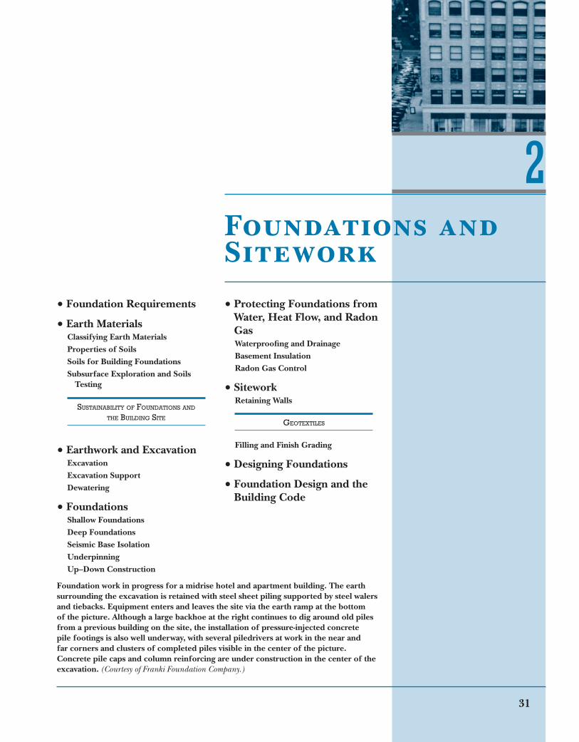
Foundation work in progress for a midrise hotel and apartment building. The earth surrounding the excavation is retained with steel sheet piling supported by steel walers and tiebacks. Equipment enters and leaves the site via the earth ramp at the bottom of the picture. Although a large backhoe at the right continues to dig around old piles from a previous building on the site, the installation of pressure-injected concrete pile footings is also well underway, with several piledrivers at work in the near and far corners and clusters of completed piles visible in the center of the picture. Concrete pile caps and column reinforcing are under construction in the center of the excavation. (Courtesy of Franki Foundation Company.)
2
Foundation Requirements
Earth MaterialsClassifying Earth MaterialsProperties of SoilsSoils for Building FoundationsSubsurface Exploration and Soils
Testing
SUSTAINABILITY OF FOUNDATIONS AND THE BUILDING SITE
Earthwork and ExcavationExcavationExcavation SupportDewatering
FoundationsShallow FoundationsDeep FoundationsSeismic Base IsolationUnderpinningUp–Down Construction
Protecting Foundations from Water, Heat Flow, and Radon GasWaterproofing and DrainageBasement InsulationRadon Gas Control
SiteworkRetaining Walls
GEOTEXTILES
Filling and Finish Grading
Designing Foundations
Foundation Design and the Building Code
Foundations and Sitework
32
structural frame, floors, roofs, and
walls, major permanent electrical
and mechanical equipment, and the
foundation itself
Live loads, nonpermanent loads
caused by the weights of the building’s
occupants, furnishings, and movable
equipment
Rain and snow loads, which act pri-
marily downward on building roofs
Wind loads, which can act laterally
(sideways), downward, or upward on
a building
Seismic loads, highly dynamic
horizontal and vertical forces caused
by the motion of the ground relative to
the building during an earthquake
Loads caused by soil and hydrostatic
pressure, including lateral soil pressure loads consisting of horizontal pressures
of earth and groundwater against base-
ment walls; in some instances, buoyant uplift forces from underground water,
identical to the forces that cause a
boat to float; in other instances, lateral
force flood loads that can occur in areas
prone to flooding
In some buildings, horizontal thrustsfrom long-span structural components
such as arches, rigid frames, domes,
vaults, or tensile structures
Foundations must limit settlement.All foundations settle to some extent
as the surrounding earth compresses
and adjusts to the loads imposed by
the building above. Over the life of
the building, settlement must not
exceed amounts that would cause
structural distress, damage nonstruc-
tural components, or interfere with
building functions.
Foundations on bedrock settle a
negligible amount. Foundations in
other types of soil may settle more, but
are normally designed to limit settling
to amounts measured in millimeters
or fractions of an inch. In rare cases,
buildings may settle by significantly
greater amounts. Mexico City’s Palace
of Fine Arts, for example, has sunk
more than 15 feet (4.5 m) into the
clay soil on which it is founded since
it was constructed in the early 1930s.
The function of a foundation is to transfer structural loads reliably from a building into the ground. Every building must have a foundation of some kind: A backyard toolshed will not be damaged by slight shifting of its foundation, and thus may need only wooden skids to spread its load across an area of the ground surface sufficient to support its weight. A wood-framed house needs greater stability than a toolshed, so its foundation reaches through the unstable surface to underlying soil that is free of organic matter and unreachable by winter frost. A larger building of masonry, steel, or concrete weighs many times more than a house, and its foundations must penetrate the earth until they reach soil or rock that is capable of carrying its massive loads; on some sites, this means going 100 feet (30 m) or more below the surface. Foundation design is a specialized field that must account for the interaction of building loads with the various soil, rock, and water conditions encountered below the surface of the ground. The choice of foundation type can have a significant impact on building costs, construction schedule, and choice of structural systems for the remainder of the building.
Foundation Requirements
The most important role of the foun-
dation is to prevent building col-
lapse. The foundation must receive
the various loads acting on the build-
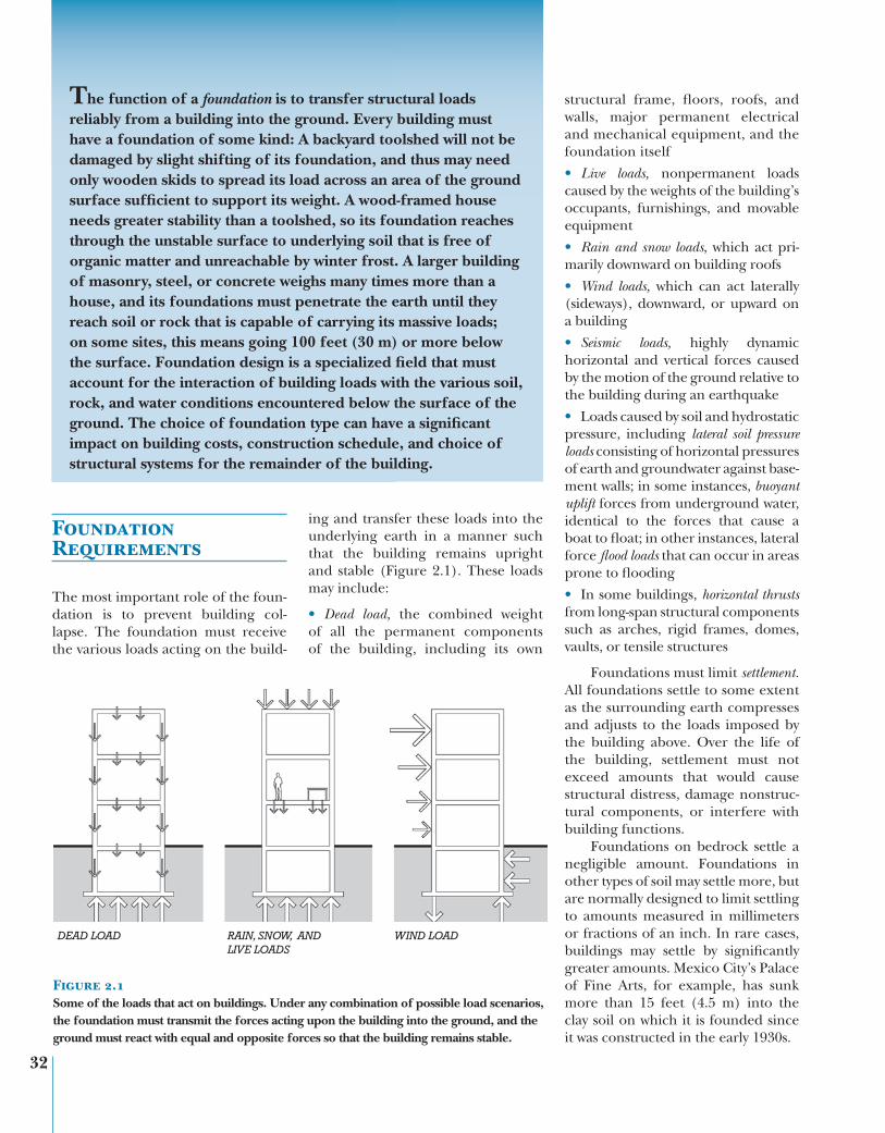
Figure 2.1Some of the loads that act on buildings. Under any combination of possible load scenarios, the foundation must transmit the forces acting upon the building into the ground, and the ground must react with equal and opposite forces so that the building remains stable.
DEAD LOAD RAIN, SNOW, ANDLIVE LOADS
WIND LOAD
ing and transfer these loads into the
underlying earth in a manner such
that the building remains upright
and stable (Figure 2.1). These loads
may include:
Dead load, the combined weight
of all the permanent components
of the building, including its own
Earth Materials / 33
We must never trust too
hastily to any ground. . . . I
have seen a tower at Mestre,
a place belonging to the
Venetians, which, in a few
years after it was built, made
its way through the ground
it stood upon . . . and buried
itself in earth up to the very
battlements.
—Leon Battista Alberti, Ten Books on Architecture, 1452
Where settling occurs at roughly
the same rate throughout all parts of
a building, it is termed uniform settle-ment. When different parts of a build-
ing settle at differing rates, it is called
differential settlement. Differential set-
tlement is most likely to occur where
soil types, building loads, or structural
systems vary among different parts of
a single building. This can lead to dis-
tortion of the building frame, sloped
floors, cracked walls and glass, or
inoperable doors and windows (Fig-
ure 2.2). Most foundation failures
are attributable to excess differential
settlement. Gross failure of a founda-
tion, in which the soil fails completely
to support the building, is rare.
Where foundations enclose base-
ments or other usable space, they
must keep those spaces dry and at
a comfortable temperature. Where
foundations are constructed close to
other existing buildings, they must not
impose new loads or alter groundwater
conditions in ways that could adversely
affect those nearby buildings. Further-
more, foundations must be feasible to
construct, both technically and eco-
nomically. These and other aspects
of foundation design are discussed at
more length in this chapter.
Earth Materials
Classifying Earth Materials
For the purposes of foundation design,
earth materials are classified according
to particle size, the presence of organic
content, and, in the case of finer-grained
soils, sensitivity to moisture content.
Consolidated rock or bedrock is a
dense, continuous mass of mineral
materials that can be removed only
by drilling, fracturing, or blasting.
Rock is rarely completely monolithic
and may vary in composition or struc-
ture, or be crossed by systems of joints
(cracks). Despite such variations,
bedrock is generally the strongest
and most stable material on which a
building can be founded.
Soil is a general term referring
to any earth material that is par-
ticulate. Particulate soils are further
defined according to ASTM D2487,
Unified Soil Classification System
(Figure 2.3), as follows:
Boulders are greater than 12 inches
(300 mm) in diameter.
Cobbles are smaller than boulders
but greater than 3 inches (75 mm) in
diameter.
Gravel is from 3 inches to 0.187 inch-
es (75 mm to 4.75 mm) in diameter.
Sand is from 0.187 inches to 0.003
inches (4.75 mm to 0.07 mm) in diameter.
Gravel and sand are also collectively
referred to as coarse-grained soils.
Silt particles are smaller than 0.0029
inches (0.075 mm). Like sand and
gravel, silt particles are roughly spheri-
cal in shape.
Clay particles are also defined
as smaller than 0.0029 inches
(0.075 mm), though typically they
are an order of magnitude (10 times)
or more smaller. Also, unlike larger-
grained particles, they are flat or plate-
shaped rather than spherical.
Both silts and clays are also referred
to as fine-grained soils.
In the field, major soil types can
be roughly distinguished with simple
hand tests. It takes two hands to lift
a boulder, and one to lift a cobble.
If you can easily lift just one particle
between two fingers, it is gravel. If indi-
vidual soil particles are large enough
to be seen, but too small to be picked
up singly, they are sand. If particles are
too small to see with the unaided eye,
they are silt or clay. When wet, clay soils
are putty-like; when dry they are hard.
Silts are not sticky when wet and have
little or no cohesiveness when dry.
Peat, topsoil, and other organic soils are not suitable for the support
of building foundations. Their high
organic matter content makes them
spongy and sensitive to changes in
water content or biological activity
within the soil.
Properties of Soils
Particle SizeCoarse-grained soils—sands and
gravels—consist of relatively large min-
eral particles with little or no attractive
or repulsive forces acting between
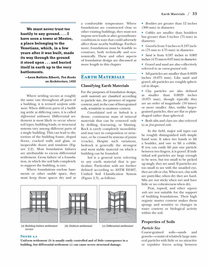
Figure 2.2Uniform settlement (b) is usually easily controlled and of little consequence in a building, but differential settlement (c) can cause severe structural damage.
(a) Building before settlement occurs
(c) Differential settlement(b) Uniform settlement
34 / Chapter 2 Foundations and Sitework
them. The ability of these soils to sup-
port building loads without shifting
depends primarily on friction between
the particles to keep the particles from
sliding past one another. This resis-
tance to internal sliding, called shear strength, varies with the degree of inter-
locking between particles and the con-
fining force of the surrounding soil.
Where coarse-grained soils are densely
packed with little space between par-
ticles and securely confined by sur-
rounding soils, it is relatively difficult
for particles to move past one another.
Soils such as these exhibit relatively
high strength and can support greater
loads. Where coarse-grained soils are
loosely packed or poorly confined,
particles can more easily slide past one
another, and less load can be safely
supported. Soils that rely primarily
on internal friction for strength are
termed frictional or cohesionless.Smaller-grained soils may be sub-
ject to a wider array of interparticle
forces. As particle size decreases, sur-
face area increases in relation to weight
and size, and the spaces between the
particles, called soil pores, get smaller.
In essence, the particles become
lighter and more easily pushed and
pulled by electrostatic forces, chemi-
cal interactions, and forces related to
the presence of water in the soil.
For example, whereas gravels are
generally little affected by moisture in
the soil, the properties of sand can vary
noticeably with moisture content. As
any beachgoer knows, wet sand makes
a stronger sand castle than dry sand, as
capillary forces acting between parti-
cles help to hold the particles in place.
And wet sand responds more firmly
to the pressure of our feet as we walk
on the beach than does dry sand, as
the hydrostatic pressure of the water
helps to distribute the load exerted
on the soil. A dramatic example of the
effects of moisture on smaller-grained
soils is a phenomenon called soil liq-uefaction. Water-saturated sands or silts
may lose virtually all of their strength
and behave as a liquid when subjected
to sudden, large changes in load, such
as may occur during an earthquake.
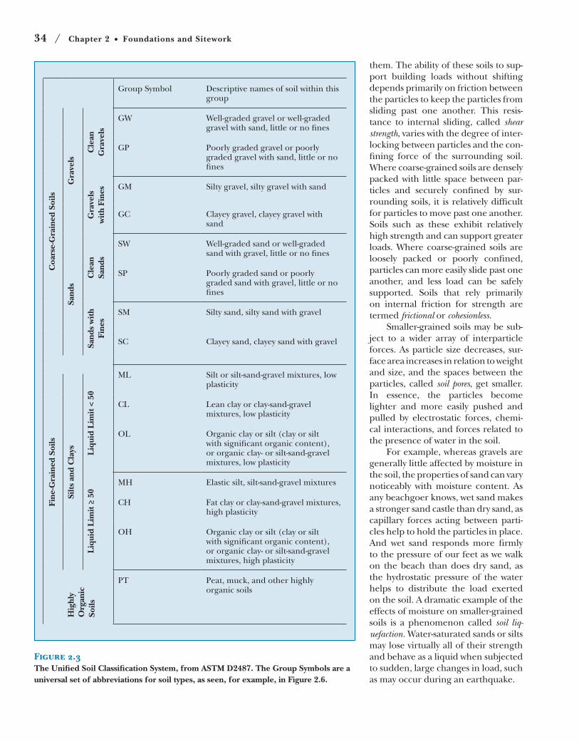
Figure 2.3The Unified Soil Classification System, from ASTM D2487. The Group Symbols are a universal set of abbreviations for soil types, as seen, for example, in Figure 2.6.
Group Symbol Descriptive names of soil within this group
Coa
rse-
Gra
ined
Soi
ls
Gra
vels
Cle
an
Gra
vels
GW Well-graded gravel or well-graded gravel with sand, little or no fines
GP Poorly graded gravel or poorly graded gravel with sand, little or no fines
Gra
vels
w
ith
Fine
s GM Silty gravel, silty gravel with sand
GC Clayey gravel, clayey gravel with sand
Sand
s
Cle
an
Sand
s
SW Well-graded sand or well-graded sand with gravel, little or no fines
SP Poorly graded sand or poorly graded sand with gravel, little or no fines
Sand
s w
ith
Fine
s
SM Silty sand, silty sand with gravel
SC Clayey sand, clayey sand with gravel
ML Silt or silt-sand-gravel mixtures, low plasticity
Fine
-Gra
ined
Soi
ls
Silt
s an
d C
lays Liq
uid
Lim
it <
50
CL Lean clay or clay-sand-gravel mixtures, low plasticity
OL Organic clay or silt (clay or silt with significant organic content), or organic clay- or silt-sand-gravel mixtures, low plasticity
Liq
uid
Lim
it ≥
50
MH Elastic silt, silt-sand-gravel mixtures
CH Fat clay or clay-sand-gravel mixtures, high plasticity
OH Organic clay or silt (clay or silt with significant organic content), or organic clay- or silt-sand-gravel mixtures, high plasticity
Hig
hly
Org
anic
So
ils
PT Peat, muck, and other highly organic soils
Earth Materials / 35
Clay particles are extremely small
in size and flatter in shape, mak-
ing the ratio of their surface area to
volume hundreds or thousands of
times greater than even silts. They
also differ in mineral composition
from larger-grained soils and tend to
arrange themselves into more com-
plex internal structures, called fabric, as particles aggregate into sheetlike
or other geometric arrangements.
As a result, clay soils tend to stick
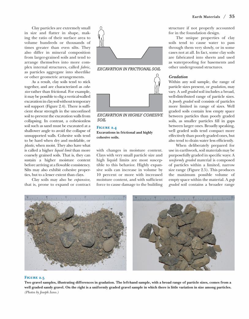
together, and are characterized as cohe-sive rather than frictional. For example,
it may be possible to dig a vertical-walled
excavation in clay soil without temporary
soil support (Figure 2.4). There is suffi-
cient shear strength in the unconfined
soil to prevent the excavation walls from
collapsing. In contrast, a cohesionless
soil such as sand must be excavated at a
shallower angle to avoid the collapse of
unsupported walls. Cohesive soils tend
to be hard when dry and moldable, or
plastic, when moist. They also have what
is called a higher liquid limit than more
coarsely grained soils. That is, they can
sustain a higher moisture content
before arriving at a flowable consistency.
Silts may also exhibit cohesive proper-
ties, but to a lesser extent than clays.
Clay soils may also be expansive, that is, prone to expand or contract
EXCAVATION IN FRICTIONAL SOIL
EXCAVATION IN HIGHLY COHESIVESOIL
Figure 2.4Excavations in frictional and highly cohesive soils.
with changes in moisture content.
Clays with very small particle size and
high liquid limits are most suscep-
tible to this behavior. Highly expan-
sive soils can increase in volume by
10 percent or more with increased
moisture content, and with sufficient
force to cause damage to the building
structure if not properly accounted
for in the foundation design.
The unique properties of clay
soils tend to cause water to pass
through them very slowly, or in some
cases not at all. In fact, some clay soils
are fabricated into sheets and used
as waterproofing for basements and
other underground structures.
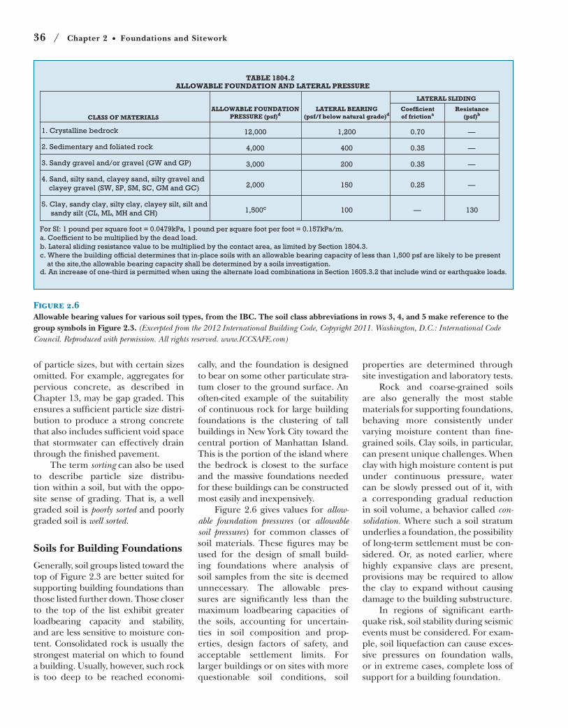
GradationWithin any soil sample, the range of
particle sizes present, or gradation, may
vary. A well graded soil includes a broad,
well-distributed range of particle sizes.
A poorly graded soil consists of particles
more limited in range of sizes. Well
graded soils contain less empty space
between particles than poorly graded
soils, as smaller particles fill in gaps
between larger ones. Broadly speaking,
well graded soils tend compact more
effectively than poorly graded ones, but
also tend to drain water less efficiently.
When deliberately prepared for
use in earthwork, soil materials may be
purposefully graded in specific ways: A
uniformly graded material is composed
of particles within a limited, narrow
size range (Figure 2.5). This produces
the maximum possible volume of
empty space within the material. A gap graded soil contains a broader range
Figure 2.5Two gravel samples, illustrating differences in gradation. The left-hand sample, with a broad range of particle sizes, comes from a well graded sandy gravel. On the right is a uniformly graded gravel sample in which there is little variation in size among particles. (Photos by Joseph Iano.)
36 / Chapter 2 Foundations and Sitework
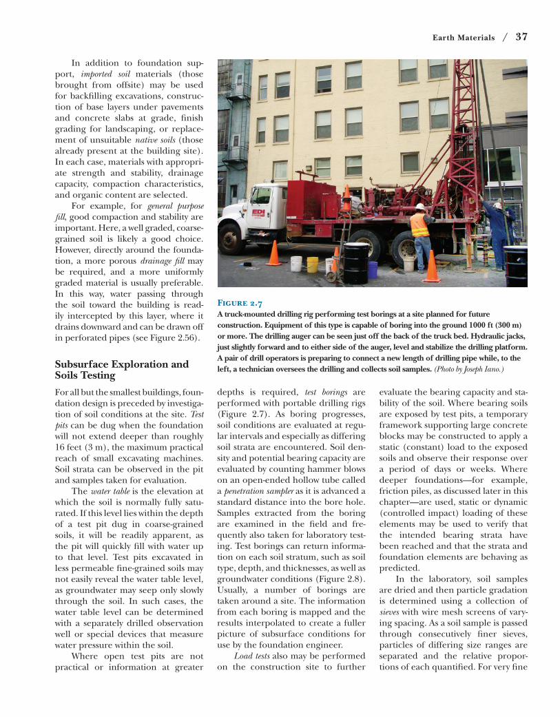
TABLE 1804.2
ALLOWABLE FOUNDATION AND LATERAL PRESSURE
CLASS OF MATERIALS
ALLOWABLE FOUNDATION
PRESSURE (psf)dLATERAL BEARING
(psf/f below natural grade)d
LATERAL SLIDING
Coefficient
of frictionaResistance
(psf)b
1. Crystalline bedrock —0.701,20012,000
2. Sedimentary and foliated rock —0.354004,000
3. Sandy gravel and/or gravel (GW and GP) —0.352003,000
4. Sand, silty sand, clayey sand, silty gravel and
clayey gravel (SW, SP, SM, SC, GM and GC) —0.251502,000
5. Clay, sandy clay, silty clay, clayey silt, silt and
sandy silt (CL, ML, MH and CH) 1,500c 130—100
For SI: 1 pound per square foot = 0.0479kPa, 1 pound per square foot per foot = 0.157kPa/m.
a. Coefficient to be multiplied by the dead load.
b. Lateral sliding resistance value to be multiplied by the contact area, as limited by Section 1804.3.
c. Where the building official determines that in-place soils with an allowable bearing capacity of less than 1,500 psf are likely to be present
at the site,the allowable bearing capacity shall be determined by a soils investigation.d. An increase of one-third is permitted when using the alternate load combinations in Section 1605.3.2 that include wind or earthquake loads.
Figure 2.6Allowable bearing values for various soil types, from the IBC. The soil class abbreviations in rows 3, 4, and 5 make reference to the group symbols in Figure 2.3. (Excerpted from the 2012 International Building Code, Copyright 2011. Washington, D.C.: International Code Council. Reproduced with permission. All rights reserved. www.ICCSAFE.com)
of particle sizes, but with certain sizes
omitted. For example, aggregates for
pervious concrete, as described in
Chapter 13, may be gap graded. This
ensures a sufficient particle size distri-
bution to produce a strong concrete
that also includes sufficient void space
that stormwater can effectively drain
through the finished pavement.
The term sorting can also be used
to describe particle size distribu-
tion within a soil, but with the oppo-
site sense of grading. That is, a well
graded soil is poorly sorted and poorly
graded soil is well sorted.
Soils for Building Foundations
Generally, soil groups listed toward the
top of Figure 2.3 are better suited for
supporting building foundations than
those listed further down. Those closer
to the top of the list exhibit greater
loadbearing capacity and stability,
and are less sensitive to moisture con-
tent. Consolidated rock is usually the
strongest material on which to found
a building. Usually, however, such rock
is too deep to be reached economi-
cally, and the foundation is designed
to bear on some other particulate stra-
tum closer to the ground surface. An
often-cited example of the suitability
of continuous rock for large building
foundations is the clustering of tall
buildings in New York City toward the
central portion of Manhattan Island.
This is the portion of the island where
the bedrock is closest to the surface
and the massive foundations needed
for these buildings can be constructed
most easily and inexpensively.
Figure 2.6 gives values for allow-able foundation pressures (or allowable soil pressures) for common classes of
soil materials. These figures may be
used for the design of small build-
ing foundations where analysis of
soil samples from the site is deemed
unnecessary. The allowable pres-
sures are significantly less than the
maximum loadbearing capacities of
the soils, accounting for uncertain-
ties in soil composition and prop-
erties, design factors of safety, and
acceptable settlement limits. For
larger buildings or on sites with more
questionable soil conditions, soil
properties are determined through
site investigation and laboratory tests.
Rock and coarse-grained soils
are also generally the most stable
materials for supporting foundations,
behaving more consistently under
varying moisture content than fine-
grained soils. Clay soils, in particular,
can present unique challenges. When
clay with high moisture content is put
under continuous pressure, water
can be slowly pressed out of it, with
a corresponding gradual reduction
in soil volume, a behavior called con-solidation. Where such a soil stratum
underlies a foundation, the possibility
of long-term settlement must be con-
sidered. Or, as noted earlier, where
highly expansive clays are present,
provisions may be required to allow
the clay to expand without causing
damage to the building substructure.
In regions of significant earth-
quake risk, soil stability during seismic
events must be considered. For exam-
ple, soil liquefaction can cause exces-
sive pressures on foundation walls,
or in extreme cases, complete loss of
support for a building foundation.
Earth Materials / 37
In addition to foundation sup-
port, imported soil materials (those
brought from offsite) may be used
for backfilling excavations, construc-
tion of base layers under pavements
and concrete slabs at grade, finish
grading for landscaping, or replace-
ment of unsuitable native soils (those
already present at the building site).
In each case, materials with appropri-
ate strength and stability, drainage
capacity, compaction characteristics,
and organic content are selected.
For example, for general purpose fill, good compaction and stability are
important. Here, a well graded, coarse-
grained soil is likely a good choice.
However, directly around the founda-
tion, a more porous drainage fill may
be required, and a more uniformly
graded material is usually preferable.
In this way, water passing through
the soil toward the building is read-
ily intercepted by this layer, where it
drains downward and can be drawn off
in perforated pipes (see Figure 2.56).
Subsurface Exploration and Soils Testing
For all but the smallest buildings, foun-
dation design is preceded by investiga-
tion of soil conditions at the site. Test pits can be dug when the foundation
will not extend deeper than roughly
16 feet (3 m), the maximum practical
reach of small excavating machines.
Soil strata can be observed in the pit
and samples taken for evaluation.
The water table is the elevation at
which the soil is normally fully satu-
rated. If this level lies within the depth
of a test pit dug in coarse-grained
soils, it will be readily apparent, as
the pit will quickly fill with water up
to that level. Test pits excavated in
less permeable fine-grained soils may
not easily reveal the water table level,
as groundwater may seep only slowly
through the soil. In such cases, the
water table level can be determined
with a separately drilled observation
well or special devices that measure
water pressure within the soil.
Where open test pits are not
practical or information at greater
depths is required, test borings are
performed with portable drilling rigs
(Figure 2.7). As boring progresses,
soil conditions are evaluated at regu-
lar intervals and especially as differing
soil strata are encountered. Soil den-
sity and potential bearing capacity are
evaluated by counting hammer blows
on an open-ended hollow tube called
a penetration sampler as it is advanced a
standard distance into the bore hole.
Samples extracted from the boring
are examined in the field and fre-
quently also taken for laboratory test-
ing. Test borings can return informa-
tion on each soil stratum, such as soil
type, depth, and thicknesses, as well as
groundwater conditions (Figure 2.8).
Usually, a number of borings are
taken around a site. The information
from each boring is mapped and the
results interpolated to create a fuller
picture of subsurface conditions for
use by the foundation engineer.
Load tests also may be performed
on the construction site to further
evaluate the bearing capacity and sta-
bility of the soil. Where bearing soils
are exposed by test pits, a temporary
framework supporting large concrete
blocks may be constructed to apply a
static (constant) load to the exposed
soils and observe their response over
a period of days or weeks. Where
deeper foundations—for example,
friction piles, as discussed later in this
chapter—are used, static or dynamic
(controlled impact) loading of these
elements may be used to verify that
the intended bearing strata have
been reached and that the strata and
foundation elements are behaving as
predicted.
In the laboratory, soil samples
are dried and then particle gradation
is determined using a collection of
sieves with wire mesh screens of vary-
ing spacing. As a soil sample is passed
through consecutively finer sieves,
particles of differing size ranges are
separated and the relative propor-
tions of each quantified. For very fine
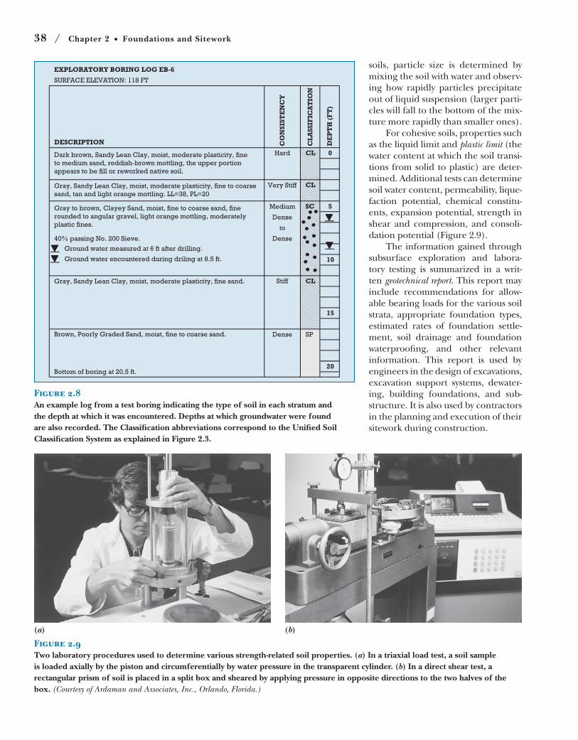
Figure 2.7A truck-mounted drilling rig performing test borings at a site planned for future construction. Equipment of this type is capable of boring into the ground 1000 ft (300 m) or more. The drilling auger can be seen just off the back of the truck bed. Hydraulic jacks, just slightly forward and to either side of the auger, level and stabilize the drilling platform. A pair of drill operators is preparing to connect a new length of drilling pipe while, to the left, a technician oversees the drilling and collects soil samples. (Photo by Joseph Iano.)
38 / Chapter 2 Foundations and Sitework
EXPLORATORY BORING LOG EB-6
SURFACE ELEVATION: 118 FT
DESCRIPTION CO
NS
IST
EN
CY
CL
AS
SIF
ICA
TIO
N
DE
PT
H (
FT
)
Hard 0CL
CL
5SC
10
Stiff CL
15
Brown, Poorly Graded Sand, moist, fine to coarse sand. SPDense
20Bottom of boring at 20.5 ft.
Dark brown, Sandy Lean Clay, moist, moderate plasticity, fine
to medium sand, reddish-brown mottling, the upper portion
appears to be fill or reworked native soil.
Gray, Sandy Lean Clay, moist, moderate plasticity, fine to coarse
sand, tan and light orange mottling. LL=38, PL=20
Very Stiff
Gray to brown, Clayey Sand, moist, fine to coarse sand, fine
rounded to angular gravel, light orange mottling, moderately
plastic fines.
40% passing No. 200 Sieve.
Ground water measured at 6 ft after drilling.
Ground water encountered during driling at 8.5 ft.
Medium
Dense
to
Dense
Gray, Sandy Lean Clay, moist, moderate plasticity, fine sand.
Figure 2.8An example log from a test boring indicating the type of soil in each stratum and the depth at which it was encountered. Depths at which groundwater were found are also recorded. The Classification abbreviations correspond to the Unified Soil Classification System as explained in Figure 2.3.
Figure 2.9Two laboratory procedures used to determine various strength-related soil properties. (a) In a triaxial load test, a soil sample is loaded axially by the piston and circumferentially by water pressure in the transparent cylinder. (b) In a direct shear test, a rectangular prism of soil is placed in a split box and sheared by applying pressure in opposite directions to the two halves of the box. (Courtesy of Ardaman and Associates, Inc., Orlando, Florida.)
(a) (b)
soils, particle size is determined by
mixing the soil with water and observ-
ing how rapidly particles precipitate
out of liquid suspension (larger parti-
cles will fall to the bottom of the mix-
ture more rapidly than smaller ones).
For cohesive soils, properties such
as the liquid limit and plastic limit (the
water content at which the soil transi-
tions from solid to plastic) are deter-
mined. Additional tests can determine
soil water content, permeability, lique-
faction potential, chemical constitu-
ents, expansion potential, strength in
shear and compression, and consoli-
dation potential (Figure 2.9).
The information gained through
subsurface exploration and labora-
tory testing is summarized in a writ-
ten geotechnical report. This report may
include recommendations for allow-
able bearing loads for the various soil
strata, appropriate foundation types,
estimated rates of foundation settle-
ment, soil drainage and foundation
waterproofing, and other relevant
information. This report is used by
engineers in the design of excavations,
excavation support systems, dewater-
ing, building foundations, and sub-
structure. It is also used by contractors
in the planning and execution of their
sitework during construction.
Earth Materials / 39
Building sites should be selected and developed to pro-
tect and conserve natural habitats and resources, enhance
sustainable community development patterns, promote
biodiversity, preserve quality open space, and minimize
pollution and unnecessary energy consumption.
Site SelectionRenovating an existing building rather than building a
new one saves energy and building materials. If it saves
the existing building from demolition, renovation also
diverts enormous quantities of material from landfill.
Building within densely populated areas with existing
infrastructure and amenities rather than in areas uncon-
nected to community resources promotes neighborhood
vitality, reduces private motor vehicle travel, and protects
undeveloped open space.
Building on a previously developed, damaged, or pol-
luted brownfield site, and designing the building so that it
restores that site, helps to mitigate previous environmen-
tal degradation.
Selecting a building site that is well connected to exist-
ing networks of public transportation, bicycle routes, and
pedestrian paths reduces fuel consumption, air pollution,
and other adverse impacts of private motor vehicle use.
Avoiding construction on prime agricultural land
preserves productive land for the future.
Avoiding construction on undeveloped, environmen-
tally sensitive land protects the wildlife and natural habi-
tats that such land supports. This includes floodplains,
land that provides habitat for endangered or threatened
species, wetlands, mature forest lands and prairies, and
land adjacent to natural bodies of water.
Avoiding construction on public parkland or land
adjacent to recreational bodies of water preserves public
open space and recreational resources.
FoundationsProperly waterproofed and drained foundations keep build-
ing interiors dry, and prevent the growth of mold and mildew.
Adequately insulated basements reduce building
energy consumption and improve occupant comfort.
In areas of high radon soil-gas risk, gas venting sys-
tems protect building occupants from high concentra-
tions of this unhealthful gas.
On building sites polluted by previous development,
soil mixing techniques can remediate in-ground contami-
nants. Where it is safe to encapsulate soil pollutants on
site, foundation systems that minimize soil displacement,
such as piles or rammed aggregate piers, minimize the
need to handle and dispose of hazardous soils.
Site DesignPreservation of mature trees, distinctive topographic for-
mations, recreational pathways, and other unique site fea-
tures prevents the loss of irreplaceable site assets.
Minimizing the building footprint preserves open
space. Protecting and enhancing unbuilt portions of the
site with natural vegetation preserves green space and ani-
mal habitat, and helps maintain biodiversity.
Appropriate landscape design and plant selection
minimize or eliminate the need for landscape irrigation
and unneeded water consumption.
Minimizing impervious ground surface area and pro-
viding drainage systems that allow the reabsorption of
stormwater into the ground work to maintain the natural
hydrology of the building site, reduce demand on munici-
pal storm sewer systems, and protect natural waterways
from overloading and pollution.
Providing vegetated or reflective roof surfaces, and
shaded or reflective paving, reduces heat island effects
and creates an improved microclimate for both humans
and wildlife.
Minimizing nighttime light pollution is a benefit to
humans and nocturnal wildlife alike.
Siting a building for optimal exposure to sun and wind
maximizes opportunities for passive heating and cooling,
and natural daylighting, all of which are strategies that
reduce building energy consumption and enhance occu-
pant comfort and productivity.
Avoiding unnecessary shading of adjacent buildings
protects those buildings’ sources of natural illumination
and useful solar heat.
Construction ProcessComplying with local and regional conservation laws con-
tributes to the protection of natural resources and animal
habitat.
Maintaining proper landscape protection prevents the
loss of difficult- or impossible-to-replace trees and vegetation.
Erosion control measures minimize the loss of soil by
wind or water action, prevent sedimentation of streams
and sewers, and minimize pollution of the air with dust
or particulates.
Stockpiling and protection of topsoil and subsoils
makes these materials available for reuse at the end of
construction or at other sites nearby.
Well-marked and properly prepared construction
vehicle access ways prevent overcompaction of soils, and
minimize noise, dust, air pollution, and inconvenience to
neighboring buildings and sites.
Recycling of construction wastes diverts solid waste
from permanent landfills.
SUSTAINABILITY OF FOUNDATIONS AND THE BUILDING SITE
40 / Chapter 2 Foundations and Sitework
Earthwork and Excavation
Virtually all building construction is
accompanied by at least some form
of earthwork during construction. On
undeveloped sites, construction may
begin with grubbing and clearing, in
which trees and plants, stumps, large
roots, and other surface materials
are removed with heavy machinery.
Next, organically rich topsoil may be
scraped away and stockpiled to one
side, to await reuse at the end of con-
struction.
Excavation
Excavation is necessary for basement
construction, to reach undisturbed,
adequately firm soil for shallow foot-
ings, for trenches for buried utilities,
and to remove native soils that are
contaminated or too weak or unsta-
ble to build over.
In particulate soils, any of a wide
variety of machines, such as bulldoz-
ers, backhoes, bucket loaders, scrap-
ers, trenching machines, and others,
may be used to loosen and lift the soil
from the ground. If the soil must be
moved more than a short distance,
dump trucks come into use.
In rock, excavation is slower
and many times more costly. Weak
or highly fractured rock may be bro-
ken up with power shovels, tractor-
mounted pneumatic hammers, or
other specialized tools. Blasting, in
which explosives are placed and deto-
nated in lines of closely spaced holes
drilled into the rock, may also be
used. Where blasting is impractical,
hydraulic splitters, devices inserted
into similarly drilled holes but which
rely on driven wedges to split the
rock, may be used.
Excavation Support
If the construction site is sufficiently
larger than the area to be covered by
the building, the edges of the excava-
tion can be sloped back or benched at a
low enough angle that the soil will not
slide back into the hole. This angle,
called the maximum allowable slope or angle of repose, can be steep for cohe-
sive soils such as stiff clays, or shal-
lower for frictional soils such as sand
and gravel. On constricted sites, the
soil surrounding an excavation must
be held back by some kind of excava-tion support capable of resisting the
pressures of earth and groundwater
(Figure 2.10). Excavation support can
take many forms, depending on the
soil type, depth of excavation, type of
construction to follow, equipment and
preferences of the contractor, proxim-
ity of surrounding roads or buildings,
and presence of groundwater.
ShoringShoring is construction used to sup-
port the sides of an excavation and
prevent its collapse. For large exca-
vations, the most common types of
shoring are soldier beams and lag-
ging, and sheet piling. With soldier
beams and lagging, steel columns
called H-piles or soldier beams are
driven vertically into the earth at
close intervals around an excavation
site before digging begins. As earth is
removed, the lagging, usually consist-
ing of heavy wood planks, is placed
against the flanges of the columns to
retain the soil outside the excavation
(Figures 2.11 and 2.12). Sheet piling
or sheeting consists of vertical sheets
of various materials that are aligned
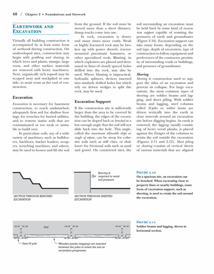
SECTION THROUGH BENCHEDEXCAVATION
SECTION THROUGH SHEETEDEXCAVATION
Bracing isrequired to resistsoil pressure
Figure 2.10On a spacious site, an excavation can be benched. When excavating close to property lines or nearby buildings, some form of excavation support, such as sheeting, is used to retain the soil around the excavation.
Steel H-pile Wooden planks (lagging) are insertedbetween the piles to retain the soil asexcavation progresses
Soil
Figure 2.11Soldier beams and lagging, shown in horizontal section.
Earthwork and Excavation / 41
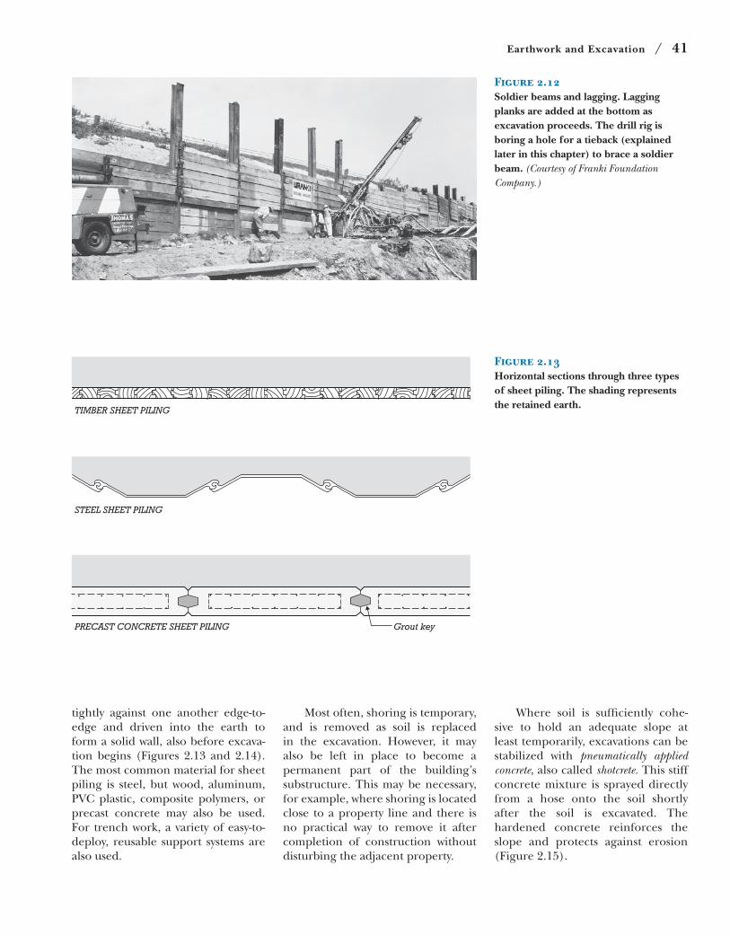
Figure 2.12Soldier beams and lagging. Lagging planks are added at the bottom as excavation proceeds. The drill rig is boring a hole for a tieback (explained later in this chapter) to brace a soldier beam. (Courtesy of Franki Foundation Company.)
TIMBER SHEET PILING
STEEL SHEET PILING
PRECAST CONCRETE SHEET PILING Grout key
Figure 2.13Horizontal sections through three types of sheet piling. The shading represents the retained earth.
tightly against one another edge-to-
edge and driven into the earth to
form a solid wall, also before excava-
tion begins (Figures 2.13 and 2.14).
The most common material for sheet
piling is steel, but wood, aluminum,
PVC plastic, composite polymers, or
precast concrete may also be used.
For trench work, a variety of easy-to-
deploy, reusable support systems are
also used.
Most often, shoring is temporary,
and is removed as soil is replaced
in the excavation. However, it may
also be left in place to become a
permanent part of the building’s
substructure. This may be necessary,
for example, where shoring is located
close to a property line and there is
no practical way to remove it after
completion of construction without
disturbing the adjacent property.
Where soil is sufficiently cohe-
sive to hold an adequate slope at
least temporarily, excavations can be
stabilized with pneumatically applied concrete, also called shotcrete. This stiff
concrete mixture is sprayed directly
from a hose onto the soil shortly
after the soil is excavated. The
hardened concrete reinforces the
slope and protects against erosion
(Figure 2.15).
42 / Chapter 2 Foundations and Sitework
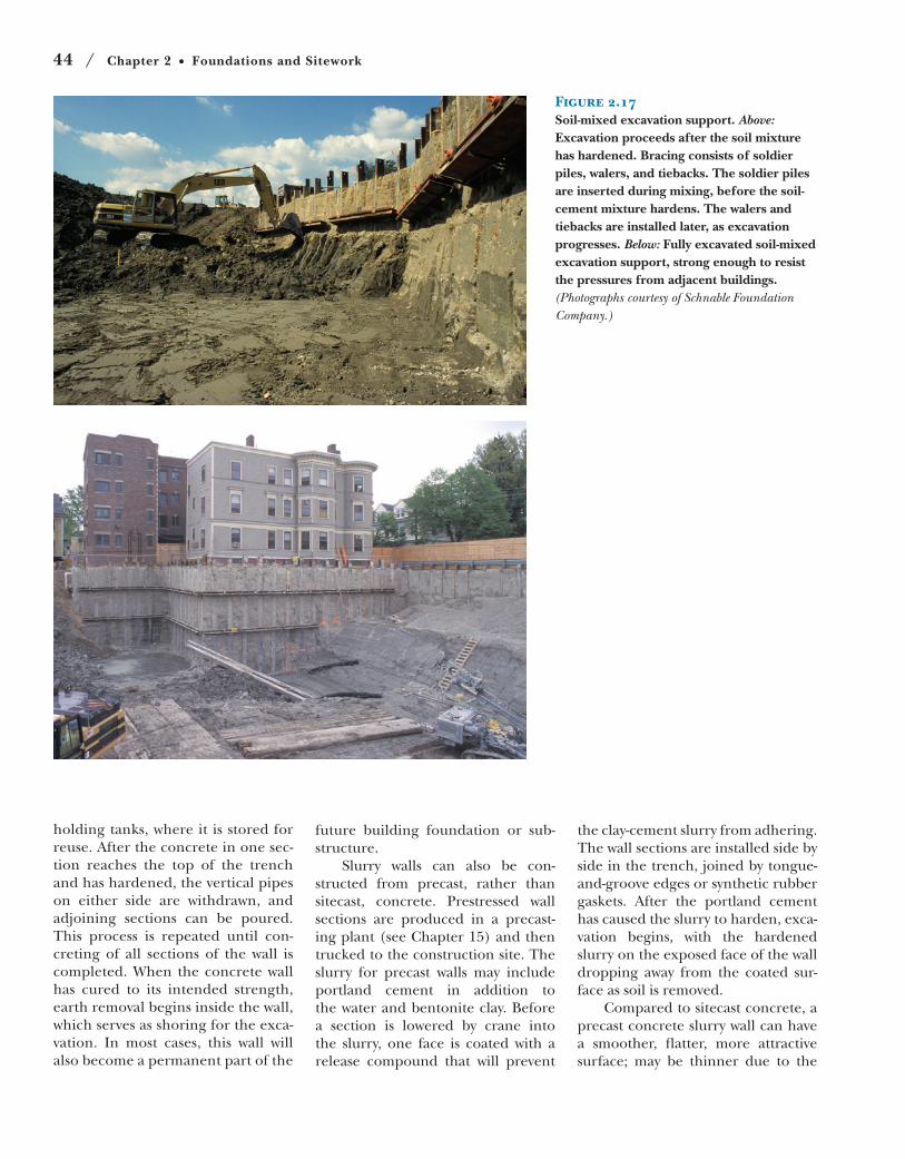
inserted into the soil-cement mix
before the mix hardens, to become
part of the bracing structure
(Figure 2.17). Soil-mixed excavation
support always remains in place,
becoming a permanent part of the
subgrade construction.
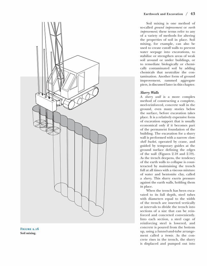
cement mix hardens into a series
of underground, abutting vertical
cylinders of low-strength concrete
against which excavation can pro-
ceed (Figure 2.16). Where bracing
is required (as discussed later in
this chapter), soldier piles can be
Soil MixingWith soil mixing, the sides of an exca-
vation are strengthened by blending
portland cement and water with the
existing soil. Mixing occurs in place,
using rotating augers or paddles
lowered into the ground. The soil-
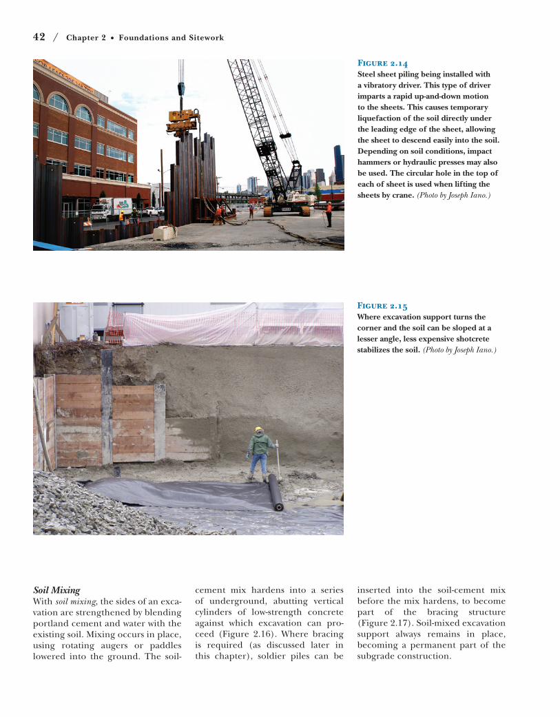
Figure 2.15Where excavation support turns the corner and the soil can be sloped at a lesser angle, less expensive shotcrete stabilizes the soil. (Photo by Joseph Iano.)
Figure 2.14Steel sheet piling being installed with a vibratory driver. This type of driver imparts a rapid up-and-down motion to the sheets. This causes temporary liquefaction of the soil directly under the leading edge of the sheet, allowing the sheet to descend easily into the soil. Depending on soil conditions, impact hammers or hydraulic presses may also be used. The circular hole in the top of each of sheet is used when lifting the sheets by crane. (Photo by Joseph Iano.)
Earthwork and Excavation / 43
Soil mixing is one method of
so-called ground improvement or earth improvement; these terms refer to any
of a variety of methods for altering
the properties of soil in place. Soil
mixing, for example, can also be
used to create cutoff walls to prevent
water seepage into excavations, to
stabilize or strengthen areas of weak
soil around or under buildings, or
to remediate biologically or chemi-
cally contaminated soil by adding
chemicals that neutralize the con-
tamination. Another form of ground
improvement, rammed aggregate
piers, is discussed later in this chapter.
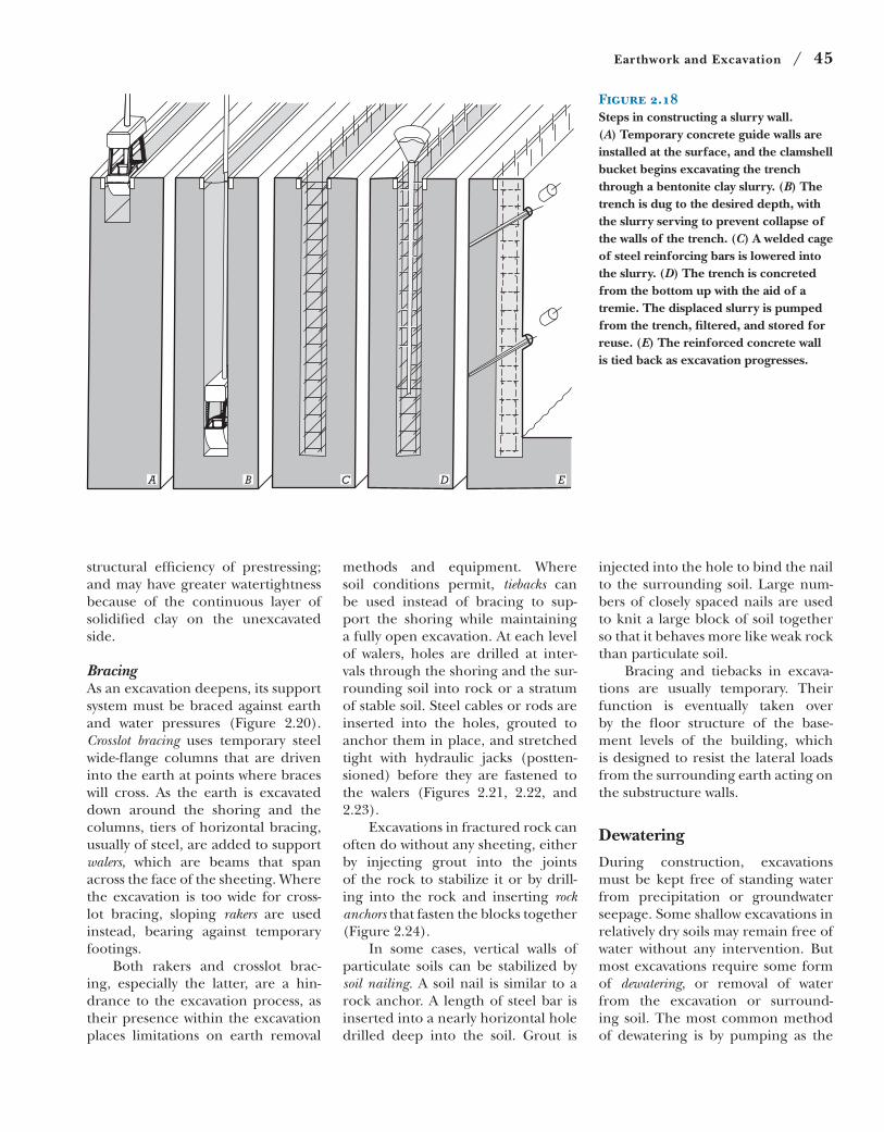
Slurry WallsA slurry wall is a more complex
method of constructing a complete,
steel-reinforced, concrete wall in the
ground, even many stories below
the surface, before excavation takes
place. It is a relatively expensive form
of excavation support that is usually
economical only if it becomes part
of the permanent foundation of the
building. The excavation for a slurry
wall is performed with a narrow clam-shell bucket, operated by crane, and
guided by temporary guides at the
ground surface defining the edges
of the wall (Figures 2.18 and 2.19).
As the trench deepens, the tendency
of the earth walls to collapse is coun-
teracted by maintaining the trench
full at all times with a viscous mixture
of water and bentonite clay, called
a slurry. This slurry exerts pressure
against the earth walls, holding them
in place.
When the trench has been exca-
vated to its full depth, steel tubes
with diameters equal to the width
of the trench are inserted vertically
at intervals to divide the trench into
sections of a size that can be rein-
forced and concreted conveniently.
Into each section, a steel cage of
reinforcing steel is lowered, and
concrete is poured from the bottom
up, using a funnel-and-tube arrange-
ment called a tremie. As the con-
crete rises in the trench, the slurry
is displaced and pumped out into
Figure 2.16Soil mixing.
44 / Chapter 2 Foundations and Sitework
Figure 2.17Soil-mixed excavation support. Above: Excavation proceeds after the soil mixture has hardened. Bracing consists of soldier piles, walers, and tiebacks. The soldier piles are inserted during mixing, before the soil-cement mixture hardens. The walers and tiebacks are installed later, as excavation progresses. Below: Fully excavated soil-mixed excavation support, strong enough to resist the pressures from adjacent buildings. (Photographs courtesy of Schnable Foundation Company.)
holding tanks, where it is stored for
reuse. After the concrete in one sec-
tion reaches the top of the trench
and has hardened, the vertical pipes
on either side are withdrawn, and
adjoining sections can be poured.
This process is repeated until con-
creting of all sections of the wall is
completed. When the concrete wall
has cured to its intended strength,
earth removal begins inside the wall,
which serves as shoring for the exca-
vation. In most cases, this wall will
also become a permanent part of the
future building foundation or sub-
structure.
Slurry walls can also be con-
structed from precast, rather than
sitecast, concrete. Prestressed wall
sections are produced in a precast-
ing plant (see Chapter 15) and then
trucked to the construction site. The
slurry for precast walls may include
portland cement in addition to
the water and bentonite clay. Before
a section is lowered by crane into
the slurry, one face is coated with a
release compound that will prevent
the clay-cement slurry from adhering.
The wall sections are installed side by
side in the trench, joined by tongue-
and-groove edges or synthetic rubber
gaskets. After the portland cement
has caused the slurry to harden, exca-
vation begins, with the hardened
slurry on the exposed face of the wall
dropping away from the coated sur-
face as soil is removed.
Compared to sitecast concrete, a
precast concrete slurry wall can have
a smoother, flatter, more attractive
surface; may be thinner due to the
Earthwork and Excavation / 45
Figure 2.18Steps in constructing a slurry wall. (A) Temporary concrete guide walls are installed at the surface, and the clamshell bucket begins excavating the trench through a bentonite clay slurry. (B) The trench is dug to the desired depth, with the slurry serving to prevent collapse of the walls of the trench. (C) A welded cage of steel reinforcing bars is lowered into the slurry. (D) The trench is concreted from the bottom up with the aid of a tremie. The displaced slurry is pumped from the trench, filtered, and stored for reuse. (E) The reinforced concrete wall is tied back as excavation progresses.
A B C D E
structural efficiency of prestressing;
and may have greater watertightness
because of the continuous layer of
solidified clay on the unexcavated
side.
BracingAs an excavation deepens, its support
system must be braced against earth
and water pressures (Figure 2.20).
Crosslot bracing uses temporary steel
wide-flange columns that are driven
into the earth at points where braces
will cross. As the earth is excavated
down around the shoring and the
columns, tiers of horizontal bracing,
usually of steel, are added to support
walers, which are beams that span
across the face of the sheeting. Where
the excavation is too wide for cross-
lot bracing, sloping rakers are used
instead, bearing against temporary
footings.
Both rakers and crosslot brac-
ing, especially the latter, are a hin-
drance to the excavation process, as
their presence within the excavation
places limitations on earth removal
methods and equipment. Where
soil conditions permit, tiebacks can
be used instead of bracing to sup-
port the shoring while maintaining
a fully open excavation. At each level
of walers, holes are drilled at inter-
vals through the shoring and the sur-
rounding soil into rock or a stratum
of stable soil. Steel cables or rods are
inserted into the holes, grouted to
anchor them in place, and stretched
tight with hydraulic jacks (postten-
sioned) before they are fastened to
the walers (Figures 2.21, 2.22, and
2.23).
Excavations in fractured rock can
often do without any sheeting, either
by injecting grout into the joints
of the rock to stabilize it or by drill-
ing into the rock and inserting rock anchors that fasten the blocks together
(Figure 2.24).
In some cases, vertical walls of
particulate soils can be stabilized by
soil nailing. A soil nail is similar to a
rock anchor. A length of steel bar is
inserted into a nearly horizontal hole
drilled deep into the soil. Grout is
injected into the hole to bind the nail
to the surrounding soil. Large num-
bers of closely spaced nails are used
to knit a large block of soil together
so that it behaves more like weak rock
than particulate soil.
Bracing and tiebacks in excava-
tions are usually temporary. Their
function is eventually taken over
by the floor structure of the base-
ment levels of the building, which
is designed to resist the lateral loads
from the surrounding earth acting on
the substructure walls.
Dewatering
During construction, excavations
must be kept free of standing water
from precipitation or groundwater
seepage. Some shallow excavations in
relatively dry soils may remain free of
water without any intervention. But
most excavations require some form
of dewatering, or removal of water
from the excavation or surround-
ing soil. The most common method
of dewatering is by pumping as the
46 / Chapter 2 Foundations and Sitework
(a) (b)
(c) (d)
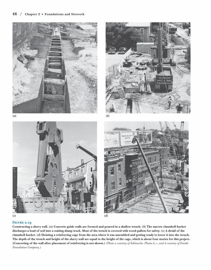
Figure 2.19Constructing a slurry wall. (a) Concrete guide walls are formed and poured in a shallow trench. (b) The narrow clamshell bucket discharges a load of soil into a waiting dump truck. Most of the trench is covered with wood pallets for safety. (c) A detail of the clamshell bucket. (d) Hoisting a reinforcing cage from the area where it was assembled and getting ready to lower it into the trench. The depth of the trench and height of the slurry wall are equal to the height of the cage, which is about four stories for this project. (Concreting of the wall after placement of reinforcing is not shown.) (Photo a courtesy of Soletanche. Photos b, c, and d courtesy of Franki Foundation Company.)
Earthwork and Excavation / 47
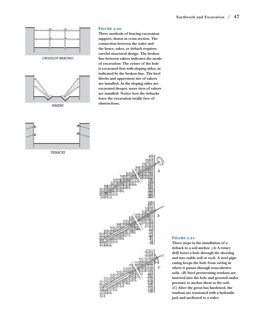
Figure 2.20Three methods of bracing excavation support, drawn in cross section. The connection between the waler and the brace, raker, or tieback requires careful structural design. The broken line between rakers indicates the mode of excavation: The center of the hole is excavated first with sloping sides, as indicated by the broken line. The heel blocks and uppermost tier of rakers are installed. As the sloping sides are excavated deeper, more tiers of rakers are installed. Notice how the tiebacks leave the excavation totally free of obstructions.
CROSSLOT BRACING
RAKERS
TIEBACKS
A
B
C
Figure 2.21Three steps in the installation of a tieback to a soil anchor. (A) A rotary drill bores a hole through the sheeting and into stable soil or rock. A steel pipe casing keeps the hole from caving in where it passes through noncohesive soils. (B) Steel prestressing tendons are inserted into the hole and grouted under pressure to anchor them to the soil. (C) After the grout has hardened, the tendons are tensioned with a hydraulic jack and anchored to a waler.
48 / Chapter 2 Foundations and Sitework
(a)
(b)
(c)
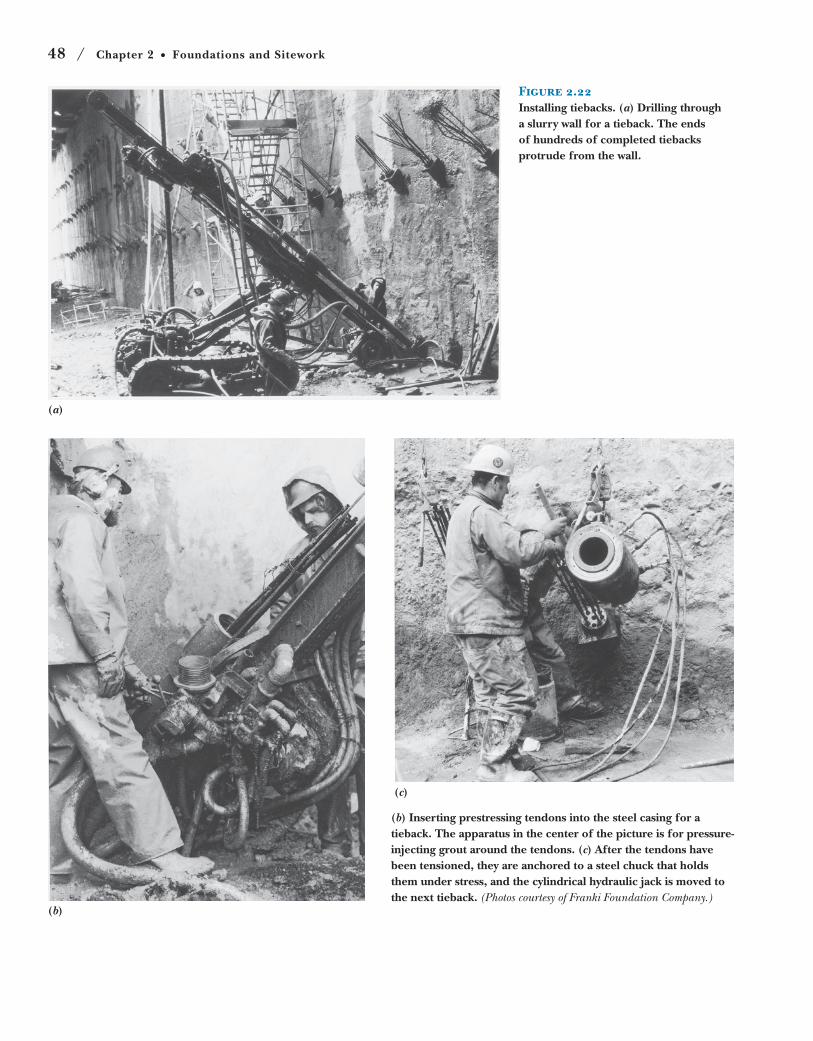
(b) Inserting prestressing tendons into the steel casing for a tieback. The apparatus in the center of the picture is for pressure-injecting grout around the tendons. (c) After the tendons have been tensioned, they are anchored to a steel chuck that holds them under stress, and the cylindrical hydraulic jack is moved to the next tieback. (Photos courtesy of Franki Foundation Company.)
Figure 2.22Installing tiebacks. (a) Drilling through a slurry wall for a tieback. The ends of hundreds of completed tiebacks protrude from the wall.
Earthwork and Excavation / 49
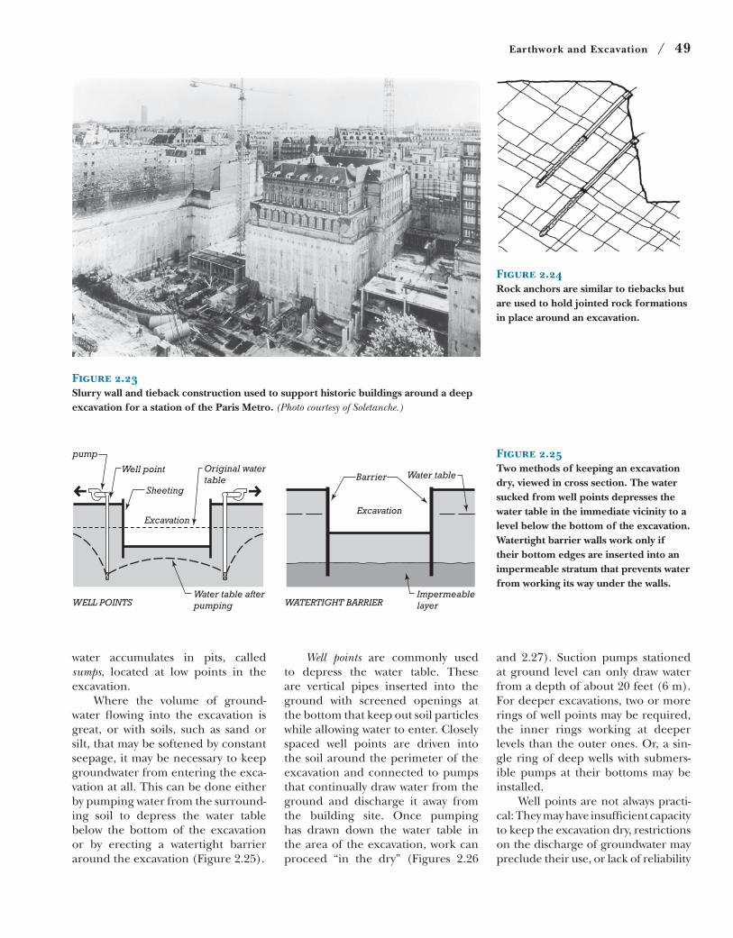
Figure 2.23Slurry wall and tieback construction used to support historic buildings around a deep excavation for a station of the Paris Metro. (Photo courtesy of Soletanche.)
Figure 2.24Rock anchors are similar to tiebacks but are used to hold jointed rock formations in place around an excavation.
pump
Well point
Sheeting
Excavation
Original watertable
Water table afterpumping WATERTIGHT BARRIER
Impermeablelayer
Barrier
Excavation
Water table
WELL POINTS
Figure 2.25Two methods of keeping an excavation dry, viewed in cross section. The water sucked from well points depresses the water table in the immediate vicinity to a level below the bottom of the excavation. Watertight barrier walls work only if their bottom edges are inserted into an impermeable stratum that prevents water from working its way under the walls.
water accumulates in pits, called
sumps, located at low points in the
excavation.
Where the volume of ground-
water flowing into the excavation is
great, or with soils, such as sand or
silt, that may be softened by constant
seepage, it may be necessary to keep
groundwater from entering the exca-
vation at all. This can be done either
by pumping water from the surround-
ing soil to depress the water table
below the bottom of the excavation
or by erecting a watertight barrier
around the excavation (Figure 2.25).
Well points are commonly used
to depress the water table. These
are vertical pipes inserted into the
ground with screened openings at
the bottom that keep out soil particles
while allowing water to enter. Closely
spaced well points are driven into
the soil around the perimeter of the
excavation and connected to pumps
that continually draw water from the
ground and discharge it away from
the building site. Once pumping
has drawn down the water table in
the area of the excavation, work can
proceed “in the dry” (Figures 2.26
and 2.27). Suction pumps stationed
at ground level can only draw water
from a depth of about 20 feet (6 m).
For deeper excavations, two or more
rings of well points may be required,
the inner rings working at deeper
levels than the outer ones. Or, a sin-
gle ring of deep wells with submers-
ible pumps at their bottoms may be
installed.
Well points are not always practi-
cal: They may have insufficient capacity
to keep the excavation dry, restrictions
on the discharge of groundwater may
preclude their use, or lack of reliability
50 / Chapter 2 Foundations and Sitework
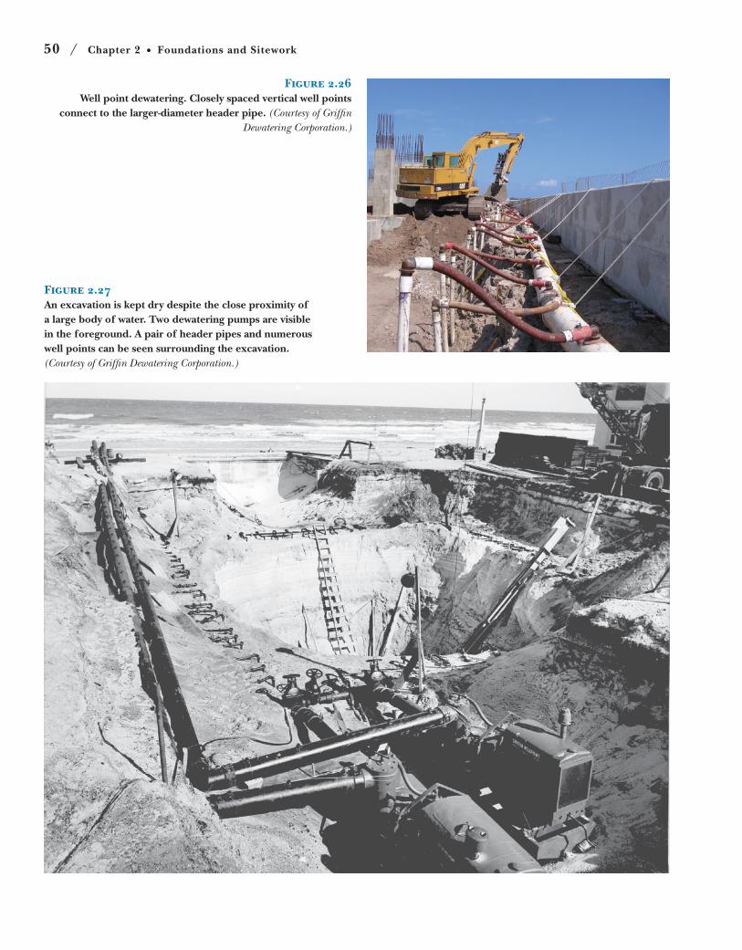
Figure 2.27An excavation is kept dry despite the close proximity of a large body of water. Two dewatering pumps are visible in the foreground. A pair of header pipes and numerous well points can be seen surrounding the excavation. (Courtesy of Griffin Dewatering Corporation.)
Figure 2.26Well point dewatering. Closely spaced vertical well points
connect to the larger-diameter header pipe. (Courtesy of Griffin Dewatering Corporation.)
Foundations / 51
above and spread them out across
an area of soil large enough that
the allowable soil pressure is not
exceeded. A column footing is a square
block of concrete, with or without steel
reinforcing, that distributes a column
load to the soil below. A wall footing or
strip footing is a continuous strip of con-
crete that serves the same function for
a loadbearing wall (Figures 2.29 and
2.30).
To minimize settlement, spread
footings must be placed on undis-
turbed soil. Alternatively, where
there are areas of unsuitable soil at
the bearing level, native soil may be
removed and replaced with engineered fill, properly formulated higher-
strength, more stable soil material
brought from offsite. This material
is placed in layers and compacted
to a specified density, usually under
the supervision of a soils engineer, to
ensure that the required loadbearing
capacity and stability are achieved.
In cold climates, footings must also
be placed below the frost line, the level
to which the ground freezes in winter.
Foundations exposed to freezing tem-
peratures can be lifted and damaged
by soil that expands as it freezes or by
ice lenses, thick layers of ice that form as
water vapor migrates upward from the
soil and is trapped under the footing.
In climates with little or no ground
freezing, the thickened edges of a con-
crete slab on grade (see Chapter 14
for further information on slabs on
grade) can function as simple, inex-
pensive spread footings for one- and
two-story buildings. Where footings
must be deeper, or floors are raised
over a crawlspace or basement, concrete
or masonry walls resting on strip foot-
ings provide support for the structure
above (Figure 2.31). When building
on slopes, strip footings are stepped,
to maintain the required depth of foot-
ing at all points around the building
(Figure 2.32). If a sloping site or earth-
quake precautions require it, column
footings may be linked together with
reinforced concrete tie beams to main-
tain stability of the footings when sub-
jected to lateral forces.
due to power outages may be a con-
cern. In some locations, lowering of
the water table could adversely affect
neighboring buildings, causing soil
consolidation under their foundations
or exposing wood foundation piles,
previously protected by immersion in
water, to decay once they contact air.
In these cases, a watertight barrier wall made from a slurry wall or soil-mixed
wall may be used (Figure 2.25). (Sheet
piling can also work, but it tends to
leak at the joints.) Soil freezing is also
possible; with this strategy, an array of
vertical pipes similar to well points is
used to circulate coolant at tempera-
tures low enough to freeze the soil
around an excavation area, resulting
in a temporary but reliable barrier to
groundwater. Watertight barriers must
resist the hydrostatic pressure of the
surrounding water, which increases
with depth, so for deeper excava-
tions, a system of bracing or tiebacks
is required. A watertight barrier also
works only if it reaches into a stratum
of impermeable soil at its bottom, such
as bedrock or water-impermeable clay.
Otherwise, water can flow underneath
the barrier and rise up from the bot-
tom of the excavation.
Foundations
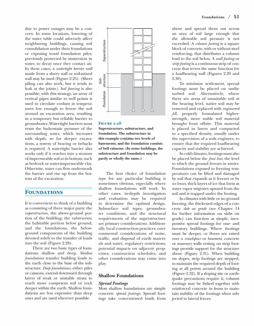
It is convenient to think of a building
as consisting of three major parts: the
superstructure, the above-ground por-
tion of the building; the substructure, the habitable portion below ground;
and the foundations, the below-
ground components of the building
devoted solely to the transfer of loads
into the soil (Figure 2.28).
There are two basic types of foun-
dations: shallow and deep. Shallow foundations transfer building loads to
the earth close to the base of the sub-
structure. Deep foundations, either piles
or caissons, extend downward through
layers of weak or unstable strata to
reach more competent soil or rock
deeper within the earth. Shallow foun-
dations are less expensive than deep
ones and are used wherever possible.
Foun
dat
ion
Sub
-st
ruct
ure
Sup
erst
ruct
ure
Figure 2.28Superstructure, substructure, and foundation. The substructure in this example contains two levels of basements, and the foundation consists of bell caissons. (In some buildings, the substructure and foundation may be partly or wholly the same.)
The best choice of foundation
type for any particular building is
sometimes obvious, especially where
shallow foundations will work. In
other cases, in-depth investigation
and evaluation may be required
to determine the optimal design.
Subsurface soil types, groundwa-
ter conditions, and the structural
requirements of the superstructure
are primary considerations. Addition-
ally, local construction practices; envi-
ronmental considerations of noise,
traffic, and disposal of earth materi-
als and water; regulatory restrictions;
potential impacts on adjacent prop-
erties; construction schedules; and
other considerations may come into
play.
Shallow Foundations
Spread FootingsMost shallow foundations are simple
concrete spread footings. Spread foot-
ings take concentrated loads from
52 / Chapter 2 Foundations and Sitework
Footings cannot legally extend
beyond a property line, even for a
building built tightly to that line. If
the outer toe of the footing were sim-
ply cut off at the property line, the
footing would be unbalanced by the
off-center column or wall above and
tend to rotate and fail. Combined foot-ings and cantilever footings solve this
problem by tying the footings for the
outside row of columns to those of the
next row in such a way that any imbal-
ance is neutralized (Figure 2.33).
Shallow Frost-Protected FoundationsWhere the frost line is deep, excava-
tion costs can be saved by construct-
ing shallow frost-protected foundations. These are footings placed closer to
the ground surface, but insulated in
such a way that the ground under-
neath them cannot freeze. Continu-
ous layers of insulation board are
placed around the perimeter of
the building in such a way that heat
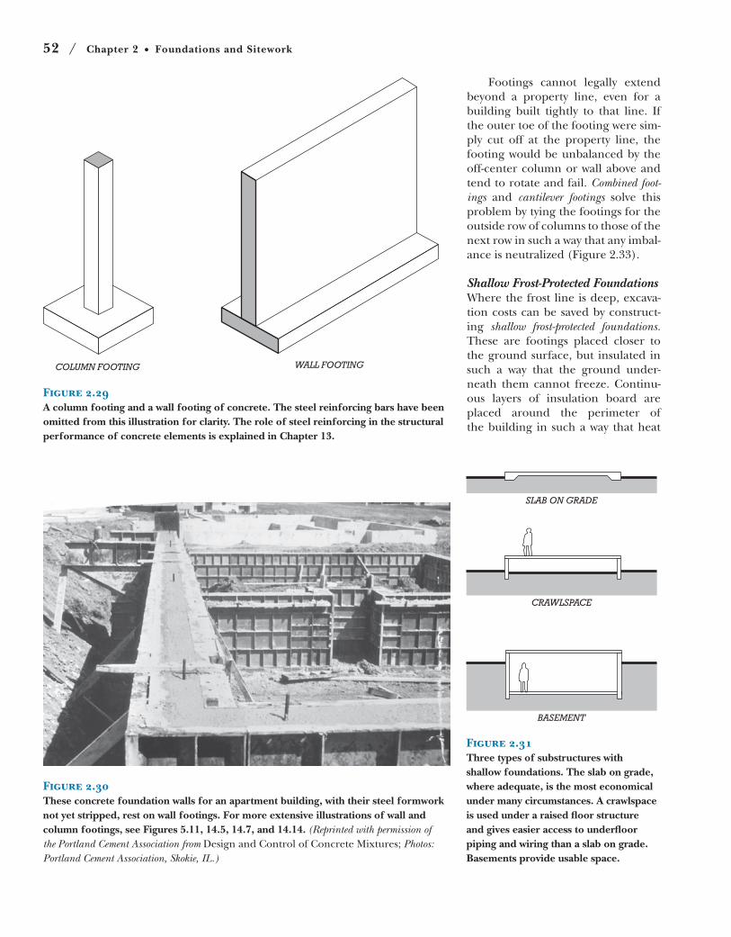
Figure 2.30These concrete foundation walls for an apartment building, with their steel formwork not yet stripped, rest on wall footings. For more extensive illustrations of wall and column footings, see Figures 5.11, 14.5, 14.7, and 14.14. (Reprinted with permission of the Portland Cement Association from Design and Control of Concrete Mixtures; Photos: Portland Cement Association, Skokie, IL.)
SLAB ON GRADE
CRAWLSPACE
BASEMENT
Figure 2.31Three types of substructures with shallow foundations. The slab on grade, where adequate, is the most economical under many circumstances. A crawlspace is used under a raised floor structure and gives easier access to underfloor piping and wiring than a slab on grade. Basements provide usable space.
COLUMN FOOTING WALL FOOTING
Figure 2.29A column footing and a wall footing of concrete. The steel reinforcing bars have been omitted from this illustration for clarity. The role of steel reinforcing in the structural performance of concrete elements is explained in Chapter 13.
Foundations / 53
STEPPED FOOTING
Tie beamsbetween columns
TIE BEAMS
Grade beam
GRADE BEAM
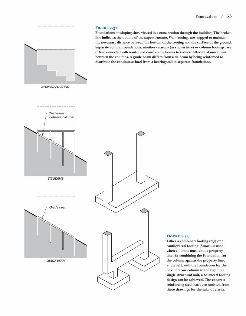
Figure 2.32Foundations on sloping sites, viewed in a cross section through the building. The broken line indicates the outline of the superstructure. Wall footings are stepped to maintain the necessary distance between the bottom of the footing and the surface of the ground. Separate column foundations, whether caissons (as shown here) or column footings, are often connected with reinforced concrete tie beams to reduce differential movement between the columns. A grade beam differs from a tie beam by being reinforced to distribute the continuous load from a bearing wall to separate foundations.
Figure 2.33Either a combined footing (top) or a cantilevered footing (bottom) is used when columns must abut a property line. By combining the foundation for the column against the property line, at the left, with the foundation for the next interior column to the right in a single structural unit, a balanced footing design can be achieved. The concrete reinforcing steel has been omitted from these drawings for the sake of clarity.

54 / Chapter 2 Foundations and Sitework
Figure 2.35Pouring a large foundation mat. Six
truck-mounted pumps receive concrete from a continuous procession of
transit-mix concrete trucks and deliver this concrete to the heavily reinforced
mat. Concrete placement continues nonstop around the clock until the
mat is finished, to avoid “cold joints,” weakened planes between hardened
concrete and fresh concrete. The soil around this excavation is supported
with a sitecast concrete slurry wall. Most of the slurry wall is tied back, but a set
of rakers is visible at the lower right. (Courtesy of Schwing America, Inc.)
flowing into the soil in winter from
the interior of the building main-
tains the soil beneath the footings at
a temperature above freezing (Fig-
ure 2.34). Even beneath unheated
buildings, properly installed thermal
insulation can trap enough geother-
mal heat around shallow foundations
to prevent freezing. The insulation
boards for shallow frost-protected
footings are made from foam plastic
or other material that can withstand
the effects of ground moisture and
earth pressures.
Mat FoundationsIn situations where the bearing
capacity of the soil is low in relation
to building loads, column footings
may become so closely spaced that it
is more effective to merge them into
a single mat or raft foundation that sup-
ports the entire building. Mat founda-
tions for very tall buildings are heavily
reinforced and may be 6 feet (1.8 m)
or more in thickness (Figure 2.35).
Wall structure
Protective coating
Plastic foam insulation
Shallow footing in inorganic soil
Figure 2.34A typical detail for a shallow frost-protected footing.
Foundations / 55
Figure 2.36A cross section through a building with a floating foundation. The building weighs approximately the same as the soil excavated for the substructure, so the stress in the soil beneath the building is the same after construction as it was before.
CA
ISSO
N
SO
CK
ET
ED
CA
ISSO
N
EN
D B
EA
RIN
G P
ILE
FRIC
TIO
N P
ILE
Figure 2.37Deep foundations. Caissons are concrete cylinders poured into drilled holes. They reach through weaker soil (light shading) to bear on competent soil beneath. The end bearing caisson at the left is belled as shown when additional bearing capacity is required. The socketed caisson is drilled into a hard stratum and transfers its load primarily by friction between the soil or rock and the sides of the caisson. Piles are driven into the earth. End bearing piles act in the same way as caissons. The friction pile derives its load-carrying capacity from friction between the soil and the sides of the pile.
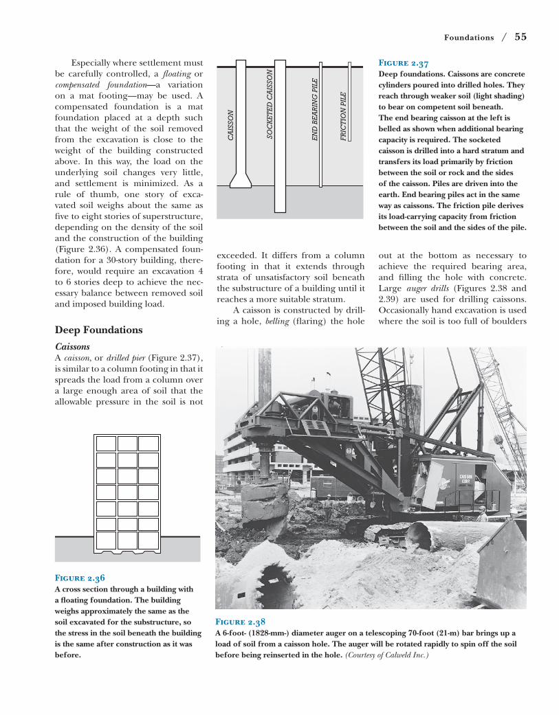
Figure 2.38A 6-foot- (1828-mm-) diameter auger on a telescoping 70-foot (21-m) bar brings up a load of soil from a caisson hole. The auger will be rotated rapidly to spin off the soil before being reinserted in the hole. (Courtesy of Calweld Inc.)
Especially where settlement must
be carefully controlled, a floating or
compensated foundation—a variation
on a mat footing—may be used. A
compensated foundation is a mat
foundation placed at a depth such
that the weight of the soil removed
from the excavation is close to the
weight of the building constructed
above. In this way, the load on the
underlying soil changes very little,
and settlement is minimized. As a
rule of thumb, one story of exca-
vated soil weighs about the same as
five to eight stories of superstructure,
depending on the density of the soil
and the construction of the building
(Figure 2.36). A compensated foun-
dation for a 30-story building, there-
fore, would require an excavation 4
to 6 stories deep to achieve the nec-
essary balance between removed soil
and imposed building load.
Deep Foundations
CaissonsA caisson, or drilled pier (Figure 2.37),
is similar to a column footing in that it
spreads the load from a column over
a large enough area of soil that the
allowable pressure in the soil is not
exceeded. It differs from a column
footing in that it extends through
strata of unsatisfactory soil beneath
the substructure of a building until it
reaches a more suitable stratum.
A caisson is constructed by drill-
ing a hole, belling (flaring) the hole
out at the bottom as necessary to
achieve the required bearing area,
and filling the hole with concrete.
Large auger drills (Figures 2.38 and
2.39) are used for drilling caissons.
Occasionally hand excavation is used
where the soil is too full of boulders
56 / Chapter 2 Foundations and Sitework
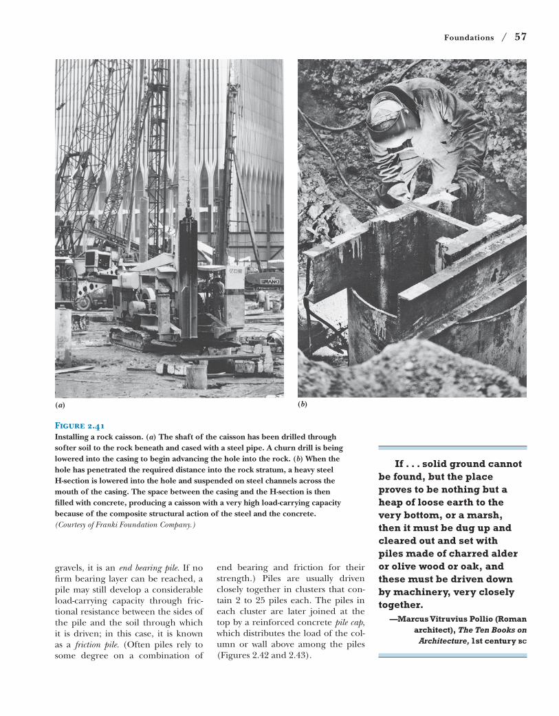
Figure 2.40The bell is formed at the bottom of the caisson shaft by a belling bucket with retractable cutters. The example shown here is for an 8-foot- (2.44-m-) diameter shaft and makes a bell 21 feet (6.40 m) in diameter. (Courtesy of Calweld Inc.)
to drill. Depending on soil condi-
tions, the soil around the drilled
hole may be temporarily supported
with a cylindrical steel casing lowered
around the drill as it progresses, or
by temporarily filling the hole with
water or a slurry, similar to slurry
wall construction. When a firm bear-
ing stratum is reached, the bell, if
required, is created at the bottom of
the shaft either by hand excavation
or by a special belling bucket on the
drill (Figure 2.40). The bearing sur-
face of the soil at the bottom of the
hole is then inspected to be sure it is
of the anticipated quality. Finally, the
hole is filled with concrete, with any
temporary casing withdrawn or water
or slurry pumped out as the concrete
rises. Reinforcing is seldom used in
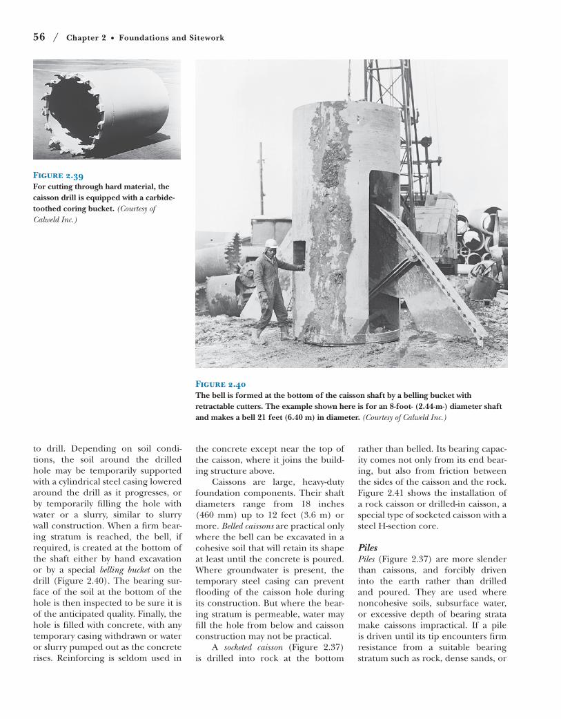
Figure 2.39For cutting through hard material, the caisson drill is equipped with a carbide-toothed coring bucket. (Courtesy of Calweld Inc.)
the concrete except near the top of
the caisson, where it joins the build-
ing structure above.
Caissons are large, heavy-duty
foundation components. Their shaft
diameters range from 18 inches
(460 mm) up to 12 feet (3.6 m) or
more. Belled caissons are practical only
where the bell can be excavated in a
cohesive soil that will retain its shape
at least until the concrete is poured.
Where groundwater is present, the
temporary steel casing can prevent
flooding of the caisson hole during
its construction. But where the bear-
ing stratum is permeable, water may
fill the hole from below and caisson
construction may not be practical.
A socketed caisson (Figure 2.37)
is drilled into rock at the bottom
rather than belled. Its bearing capac-
ity comes not only from its end bear-
ing, but also from friction between
the sides of the caisson and the rock.
Figure 2.41 shows the installation of
a rock caisson or drilled-in caisson, a
special type of socketed caisson with a
steel H-section core.
PilesPiles (Figure 2.37) are more slender
than caissons, and forcibly driven
into the earth rather than drilled
and poured. They are used where
noncohesive soils, subsurface water,
or excessive depth of bearing strata
make caissons impractical. If a pile
is driven until its tip encounters firm
resistance from a suitable bearing
stratum such as rock, dense sands, or
Foundations / 57
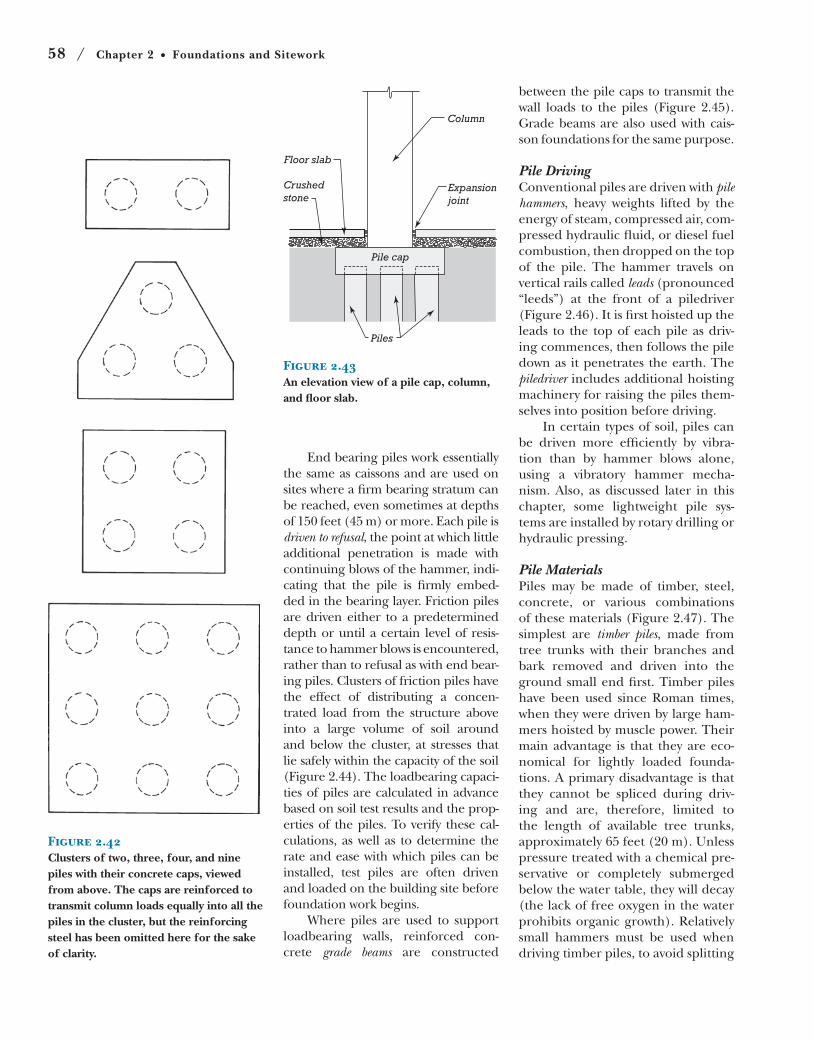
Figure 2.41Installing a rock caisson. (a) The shaft of the caisson has been drilled through softer soil to the rock beneath and cased with a steel pipe. A churn drill is being lowered into the casing to begin advancing the hole into the rock. (b) When the hole has penetrated the required distance into the rock stratum, a heavy steel H-section is lowered into the hole and suspended on steel channels across the mouth of the casing. The space between the casing and the H-section is then filled with concrete, producing a caisson with a very high load-carrying capacity because of the composite structural action of the steel and the concrete. (Courtesy of Franki Foundation Company.)
(a) (b)
gravels, it is an end bearing pile. If no
firm bearing layer can be reached, a
pile may still develop a considerable
load-carrying capacity through fric-
tional resistance between the sides of
the pile and the soil through which
it is driven; in this case, it is known
as a friction pile. (Often piles rely to
some degree on a combination of
end bearing and friction for their
strength.) Piles are usually driven
closely together in clusters that con-
tain 2 to 25 piles each. The piles in
each cluster are later joined at the
top by a reinforced concrete pile cap,
which distributes the load of the col-
umn or wall above among the piles
(Figures 2.42 and 2.43).
If . . . solid ground cannot
be found, but the place
proves to be nothing but a
heap of loose earth to the
very bottom, or a marsh,
then it must be dug up and
cleared out and set with
piles made of charred alder
or olive wood or oak, and
these must be driven down
by machinery, very closely
together.
—Marcus Vitruvius Pollio (Roman
architect), The Ten Books on Architecture, 1st century BC
58 / Chapter 2 Foundations and Sitework
Figure 2.43An elevation view of a pile cap, column, and floor slab.
Floor slab
Crushedstone
Column
Expansionjoint
Pile cap
Piles
Figure 2.42Clusters of two, three, four, and nine piles with their concrete caps, viewed from above. The caps are reinforced to transmit column loads equally into all the piles in the cluster, but the reinforcing steel has been omitted here for the sake of clarity.
End bearing piles work essentially
the same as caissons and are used on
sites where a firm bearing stratum can
be reached, even sometimes at depths
of 150 feet (45 m) or more. Each pile is
driven to refusal, the point at which little
additional penetration is made with
continuing blows of the hammer, indi-
cating that the pile is firmly embed-
ded in the bearing layer. Friction piles
are driven either to a predetermined
depth or until a certain level of resis-
tance to hammer blows is encountered,
rather than to refusal as with end bear-
ing piles. Clusters of friction piles have
the effect of distributing a concen-
trated load from the structure above
into a large volume of soil around
and below the cluster, at stresses that
lie safely within the capacity of the soil
(Figure 2.44). The loadbearing capaci-
ties of piles are calculated in advance
based on soil test results and the prop-
erties of the piles. To verify these cal-
culations, as well as to determine the
rate and ease with which piles can be
installed, test piles are often driven
and loaded on the building site before
foundation work begins.
Where piles are used to support
loadbearing walls, reinforced con-
crete grade beams are constructed
between the pile caps to transmit the
wall loads to the piles (Figure 2.45).
Grade beams are also used with cais-
son foundations for the same purpose.
Pile DrivingConventional piles are driven with pile hammers, heavy weights lifted by the
energy of steam, compressed air, com-
pressed hydraulic fluid, or diesel fuel
combustion, then dropped on the top
of the pile. The hammer travels on
vertical rails called leads (pronounced
“leeds”) at the front of a piledriver
(Figure 2.46). It is first hoisted up the
leads to the top of each pile as driv-
ing commences, then follows the pile
down as it penetrates the earth. The
piledriver includes additional hoisting
machinery for raising the piles them-
selves into position before driving.
In certain types of soil, piles can
be driven more efficiently by vibra-
tion than by hammer blows alone,
using a vibratory hammer mecha-
nism. Also, as discussed later in this
chapter, some lightweight pile sys-
tems are installed by rotary drilling or
hydraulic pressing.
Pile MaterialsPiles may be made of timber, steel,
concrete, or various combinations
of these materials (Figure 2.47). The
simplest are timber piles, made from
tree trunks with their branches and
bark removed and driven into the
ground small end first. Timber piles
have been used since Roman times,
when they were driven by large ham-
mers hoisted by muscle power. Their
main advantage is that they are eco-
nomical for lightly loaded founda-
tions. A primary disadvantage is that
they cannot be spliced during driv-
ing and are, therefore, limited to
the length of available tree trunks,
approximately 65 feet (20 m). Unless
pressure treated with a chemical pre-
servative or completely submerged
below the water table, they will decay
(the lack of free oxygen in the water
prohibits organic growth). Relatively
small hammers must be used when
driving timber piles, to avoid splitting
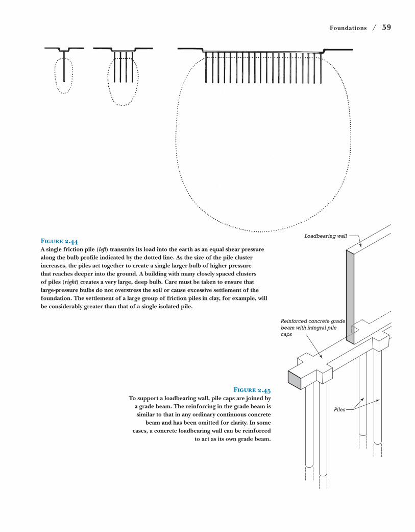
Foundations / 59
Figure 2.44A single friction pile (left) transmits its load into the earth as an equal shear pressure along the bulb profile indicated by the dotted line. As the size of the pile cluster increases, the piles act together to create a single larger bulb of higher pressure that reaches deeper into the ground. A building with many closely spaced clusters of piles (right) creates a very large, deep bulb. Care must be taken to ensure that large-pressure bulbs do not overstress the soil or cause excessive settlement of the foundation. The settlement of a large group of friction piles in clay, for example, will be considerably greater than that of a single isolated pile.
Figure 2.45To support a loadbearing wall, pile caps are joined by
a grade beam. The reinforcing in the grade beam is similar to that in any ordinary continuous concrete
beam and has been omitted for clarity. In some cases, a concrete loadbearing wall can be reinforced
to act as its own grade beam.
Reinforced concrete gradebeam with integral pilecaps
Piles
Loadbearing wall
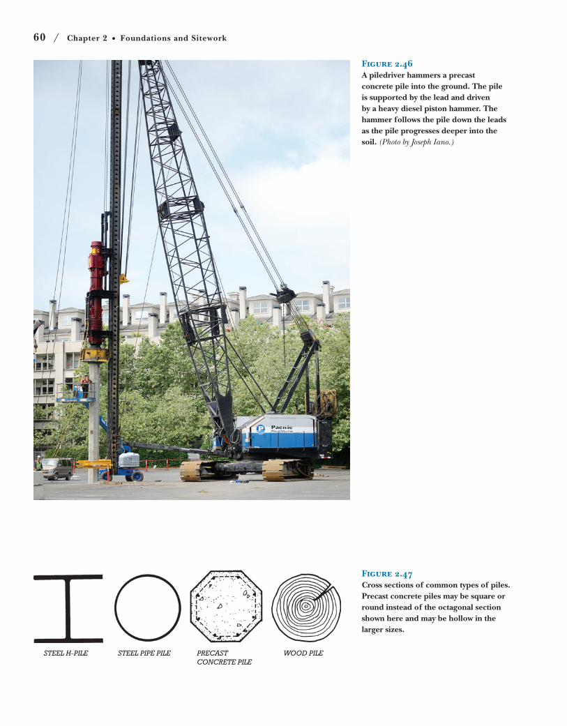
60 / Chapter 2 Foundations and Sitework
Figure 2.46A piledriver hammers a precast concrete pile into the ground. The pile is supported by the lead and driven by a heavy diesel piston hammer. The hammer follows the pile down the leads as the pile progresses deeper into the soil. (Photo by Joseph Iano.)
STEEL H-PILE STEEL PIPE PILE PRECASTCONCRETE PILE
WOOD PILE
Figure 2.47Cross sections of common types of piles. Precast concrete piles may be square or round instead of the octagonal section shown here and may be hollow in the larger sizes.
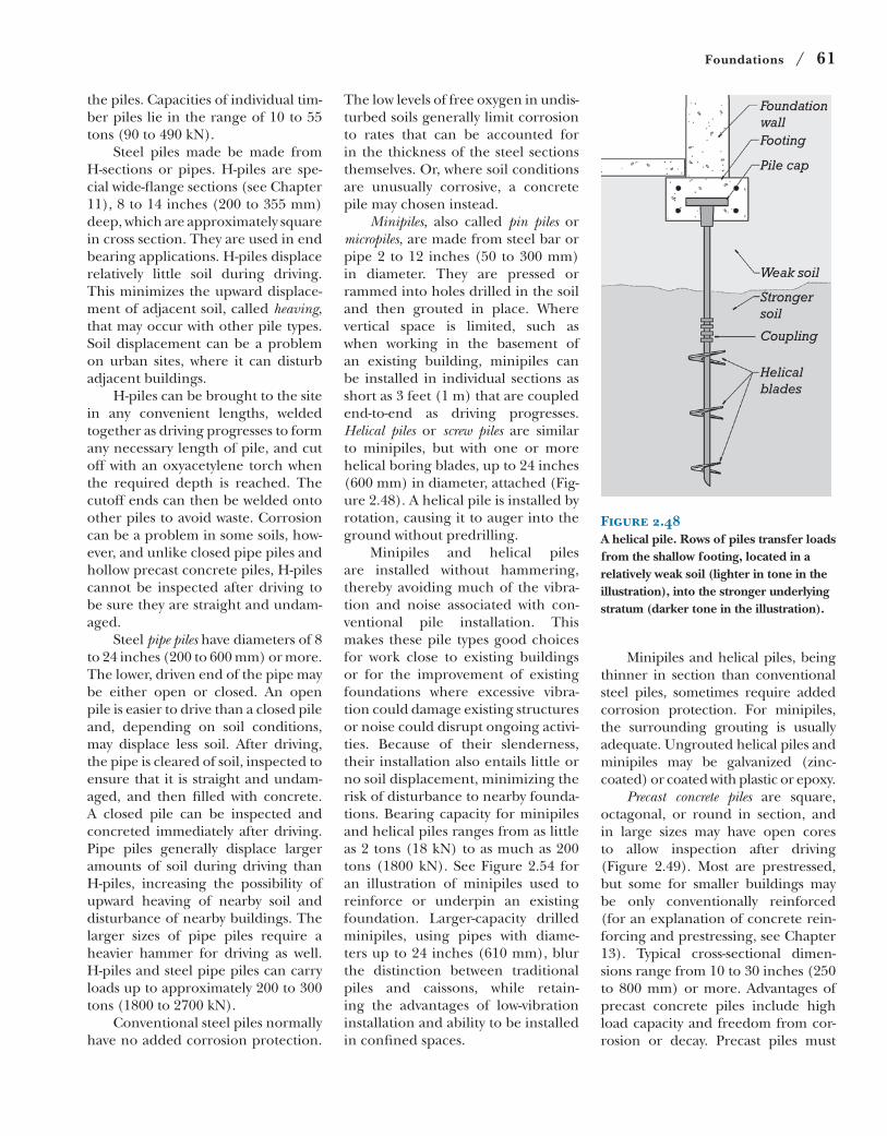
Foundations / 61
Minipiles and helical piles, being
thinner in section than conventional
steel piles, sometimes require added
corrosion protection. For minipiles,
the surrounding grouting is usually
adequate. Ungrouted helical piles and
minipiles may be galvanized (zinc-
coated) or coated with plastic or epoxy.
Precast concrete piles are square,
octagonal, or round in section, and
in large sizes may have open cores
to allow inspection after driving
(Figure 2.49). Most are prestressed,
but some for smaller buildings may
be only conventionally reinforced
(for an explanation of concrete rein-
forcing and prestressing, see Chapter
13). Typical cross-sectional dimen-
sions range from 10 to 30 inches (250
to 800 mm) or more. Advantages of
precast concrete piles include high
load capacity and freedom from cor-
rosion or decay. Precast piles must
The low levels of free oxygen in undis-
turbed soils generally limit corrosion
to rates that can be accounted for
in the thickness of the steel sections
themselves. Or, where soil conditions
are unusually corrosive, a concrete
pile may chosen instead.
Minipiles, also called pin piles or
micropiles, are made from steel bar or
pipe 2 to 12 inches (50 to 300 mm)
in diameter. They are pressed or
rammed into holes drilled in the soil
and then grouted in place. Where
vertical space is limited, such as
when working in the basement of
an existing building, minipiles can
be installed in individual sections as
short as 3 feet (1 m) that are coupled
end-to-end as driving progresses.
Helical piles or screw piles are similar
to minipiles, but with one or more
helical boring blades, up to 24 inches
(600 mm) in diameter, attached (Fig-
ure 2.48). A helical pile is installed by
rotation, causing it to auger into the
ground without predrilling.
Minipiles and helical piles
are installed without hammering,
thereby avoiding much of the vibra-
tion and noise associated with con-
ventional pile installation. This
makes these pile types good choices
for work close to existing buildings
or for the improvement of existing
foundations where excessive vibra-
tion could damage existing structures
or noise could disrupt ongoing activi-
ties. Because of their slenderness,
their installation also entails little or
no soil displacement, minimizing the
risk of disturbance to nearby founda-
tions. Bearing capacity for minipiles
and helical piles ranges from as little
as 2 tons (18 kN) to as much as 200
tons (1800 kN). See Figure 2.54 for
an illustration of minipiles used to
reinforce or underpin an existing
foundation. Larger-capacity drilled
minipiles, using pipes with diame-
ters up to 24 inches (610 mm), blur
the distinction between traditional
piles and caissons, while retain-
ing the advantages of low-vibration
installation and ability to be installed
in confined spaces.
FoundationwallFooting
Pile cap
Weak soil
Strongersoil
Coupling
Helicalblades
Figure 2.48A helical pile. Rows of piles transfer loads from the shallow footing, located in a relatively weak soil (lighter in tone in the illustration), into the stronger underlying stratum (darker tone in the illustration).
the piles. Capacities of individual tim-
ber piles lie in the range of 10 to 55
tons (90 to 490 kN).
Steel piles made be made from
H-sections or pipes. H-piles are spe-
cial wide-flange sections (see Chapter
11), 8 to 14 inches (200 to 355 mm)
deep, which are approximately square
in cross section. They are used in end
bearing applications. H-piles displace
relatively little soil during driving.
This minimizes the upward displace-
ment of adjacent soil, called heaving,
that may occur with other pile types.
Soil displacement can be a problem
on urban sites, where it can disturb
adjacent buildings.
H-piles can be brought to the site
in any convenient lengths, welded
together as driving progresses to form
any necessary length of pile, and cut
off with an oxyacetylene torch when
the required depth is reached. The
cutoff ends can then be welded onto
other piles to avoid waste. Corrosion
can be a problem in some soils, how-
ever, and unlike closed pipe piles and
hollow precast concrete piles, H-piles
cannot be inspected after driving to
be sure they are straight and undam-
aged.
Steel pipe piles have diameters of 8
to 24 inches (200 to 600 mm) or more.
The lower, driven end of the pipe may
be either open or closed. An open
pile is easier to drive than a closed pile
and, depending on soil conditions,
may displace less soil. After driving,
the pipe is cleared of soil, inspected to
ensure that it is straight and undam-
aged, and then filled with concrete.
A closed pile can be inspected and
concreted immediately after driving.
Pipe piles generally displace larger
amounts of soil during driving than
H-piles, increasing the possibility of
upward heaving of nearby soil and
disturbance of nearby buildings. The
larger sizes of pipe piles require a
heavier hammer for driving as well.
H-piles and steel pipe piles can carry
loads up to approximately 200 to 300
tons (1800 to 2700 kN).
Conventional steel piles normally
have no added corrosion protection.
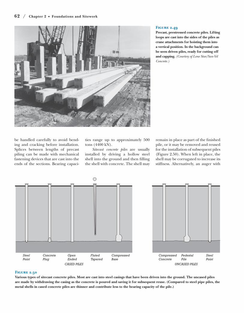
62 / Chapter 2 Foundations and Sitework
SteelPoint
ConcretePlug
OpenEnded
FlutedTapered
CompressedBase
CompressedConcrete
PedestalPile
UNCASED PILESCASED PILES
SteelPoint
Figure 2.50Various types of sitecast concrete piles. Most are cast into steel casings that have been driven into the ground. The uncased piles are made by withdrawing the casing as the concrete is poured and saving it for subsequent reuse. (Compared to steel pipe piles, the metal shells in cased concrete piles are thinner and contribute less to the bearing capacity of the pile.)
Figure 2.49Precast, prestressed concrete piles. Lifting loops are cast into the sides of the piles as crane attachments for hoisting them into a vertical position. In the background can be seen driven piles, ready for cutting off and capping. (Courtesy of Lone Star/San-Vel Concrete.)
be handled carefully to avoid bend-
ing and cracking before installation.
Splices between lengths of precast
piling can be made with mechanical
fastening devices that are cast into the
ends of the sections. Bearing capaci-
ties range up to approximately 500
tons (4400 kN).
Sitecast concrete piles are usually
installed by driving a hollow steel
shell into the ground and then filling
the shell with concrete. The shell may
remain in place as part of the finished
pile, or it may be removed and reused
for the installation of subsequent piles
(Figure 2.50). When left in place, the
shell may be corrugated to increase its
stiffness. Alternatively, an auger with
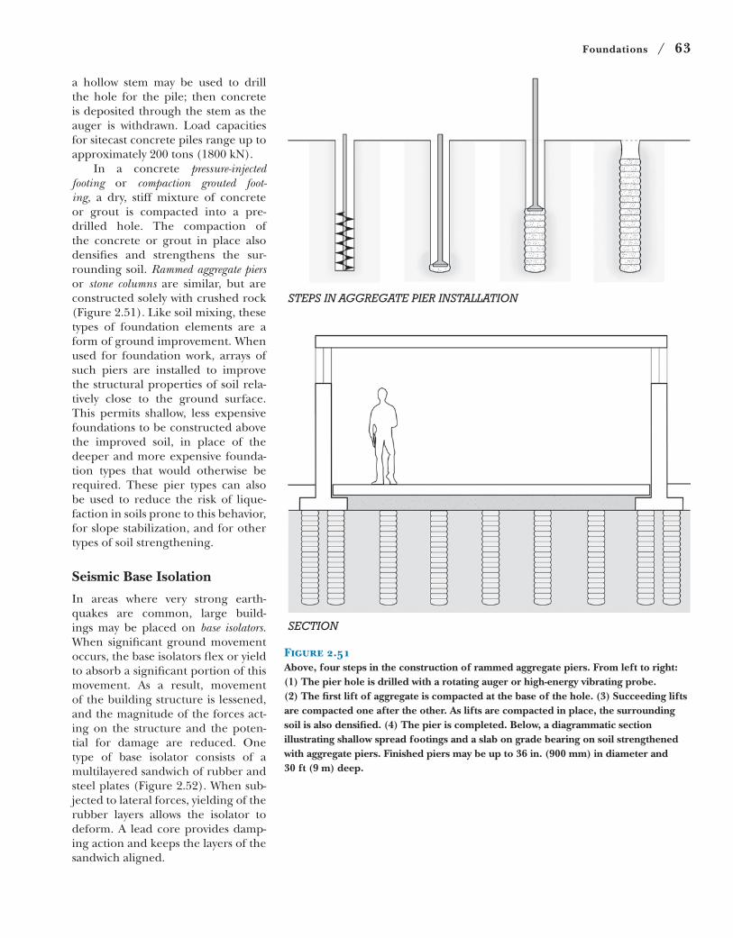
Foundations / 63
STEPS IN AGGREGATE PIER INSTALLATION
SECTION
Figure 2.51Above, four steps in the construction of rammed aggregate piers. From left to right: (1) The pier hole is drilled with a rotating auger or high-energy vibrating probe. (2) The first lift of aggregate is compacted at the base of the hole. (3) Succeeding lifts are compacted one after the other. As lifts are compacted in place, the surrounding soil is also densified. (4) The pier is completed. Below, a diagrammatic section illustrating shallow spread footings and a slab on grade bearing on soil strengthened with aggregate piers. Finished piers may be up to 36 in. (900 mm) in diameter and 30 ft (9 m) deep.
a hollow stem may be used to drill
the hole for the pile; then concrete
is deposited through the stem as the
auger is withdrawn. Load capacities
for sitecast concrete piles range up to
approximately 200 tons (1800 kN).
In a concrete pressure-injected footing or compaction grouted foot-ing, a dry, stiff mixture of concrete
or grout is compacted into a pre-
drilled hole. The compaction of
the concrete or grout in place also
densifies and strengthens the sur-
rounding soil. Rammed aggregate piers or stone columns are similar, but are
constructed solely with crushed rock
(Figure 2.51). Like soil mixing, these
types of foundation elements are a
form of ground improvement. When
used for foundation work, arrays of
such piers are installed to improve
the structural properties of soil rela-
tively close to the ground surface.
This permits shallow, less expensive
foundations to be constructed above
the improved soil, in place of the
deeper and more expensive founda-
tion types that would otherwise be
required. These pier types can also
be used to reduce the risk of lique-
faction in soils prone to this behavior,
for slope stabilization, and for other
types of soil strengthening.
Seismic Base Isolation
In areas where very strong earth-
quakes are common, large build-
ings may be placed on base isolators. When significant ground movement
occurs, the base isolators flex or yield
to absorb a significant portion of this
movement. As a result, movement
of the building structure is lessened,
and the magnitude of the forces act-
ing on the structure and the poten-
tial for damage are reduced. One
type of base isolator consists of a
multilayered sandwich of rubber and
steel plates (Figure 2.52). When sub-
jected to lateral forces, yielding of the
rubber layers allows the isolator to
deform. A lead core provides damp-
ing action and keeps the layers of the
sandwich aligned.
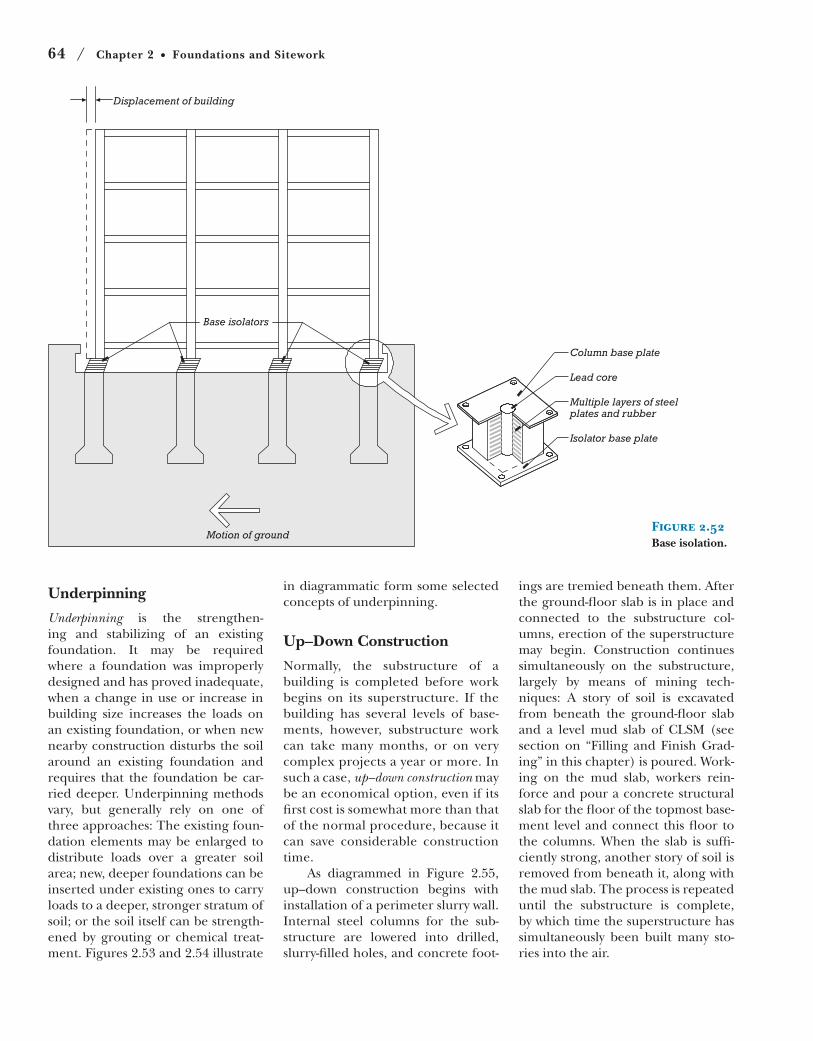
64 / Chapter 2 Foundations and Sitework
Displacement of building
Base isolators
Motion of ground
Column base plate
Lead core
Multiple layers of steelplates and rubber
Isolator base plate
Figure 2.52Base isolation.
Underpinning
Underpinning is the strengthen-
ing and stabilizing of an existing
foundation. It may be required
where a foundation was improperly
designed and has proved inadequate,
when a change in use or increase in
building size increases the loads on
an existing foundation, or when new
nearby construction disturbs the soil
around an existing foundation and
requires that the foundation be car-
ried deeper. Underpinning methods
vary, but generally rely on one of
three approaches: The existing foun-
dation elements may be enlarged to
distribute loads over a greater soil
area; new, deeper foundations can be
inserted under existing ones to carry
loads to a deeper, stronger stratum of
soil; or the soil itself can be strength-
ened by grouting or chemical treat-
ment. Figures 2.53 and 2.54 illustrate
in diagrammatic form some selected
concepts of underpinning.
Up–Down Construction
Normally, the substructure of a
building is completed before work
begins on its superstructure. If the
building has several levels of base-
ments, however, substructure work
can take many months, or on very
complex projects a year or more. In
such a case, up–down construction may
be an economical option, even if its
first cost is somewhat more than that
of the normal procedure, because it
can save considerable construction
time.
As diagrammed in Figure 2.55,
up–down construction begins with
installation of a perimeter slurry wall.
Internal steel columns for the sub-
structure are lowered into drilled,
slurry-filled holes, and concrete foot-
ings are tremied beneath them. After
the ground-floor slab is in place and
connected to the substructure col-
umns, erection of the superstructure
may begin. Construction continues
simultaneously on the substructure,
largely by means of mining tech-
niques: A story of soil is excavated
from beneath the ground-floor slab
and a level mud slab of CLSM (see
section on “Filling and Finish Grad-
ing” in this chapter) is poured. Work-
ing on the mud slab, workers rein-
force and pour a concrete structural
slab for the floor of the topmost base-
ment level and connect this floor to
the columns. When the slab is suffi-
ciently strong, another story of soil is
removed from beneath it, along with
the mud slab. The process is repeated
until the substructure is complete,
by which time the superstructure has
simultaneously been built many sto-
ries into the air.
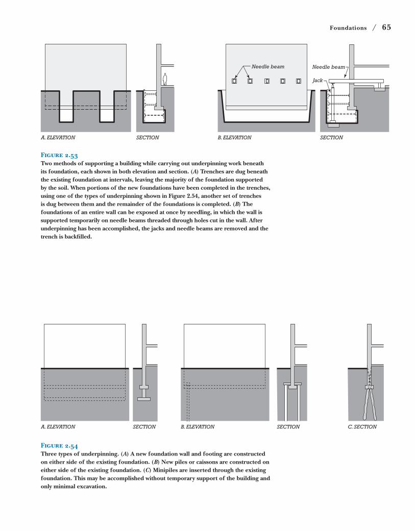
Foundations / 65
A. ELEVATION SECTION SECTION
Jack
Needle beamNeedle beam
B. ELEVATION
Figure 2.53Two methods of supporting a building while carrying out underpinning work beneath its foundation, each shown in both elevation and section. (A) Trenches are dug beneath the existing foundation at intervals, leaving the majority of the foundation supported by the soil. When portions of the new foundations have been completed in the trenches, using one of the types of underpinning shown in Figure 2.54, another set of trenches is dug between them and the remainder of the foundations is completed. (B) The foundations of an entire wall can be exposed at once by needling, in which the wall is supported temporarily on needle beams threaded through holes cut in the wall. After underpinning has been accomplished, the jacks and needle beams are removed and the trench is backfilled.
A. ELEVATION SECTION SECTION C. SECTIONB. ELEVATION
Figure 2.54Three types of underpinning. (A) A new foundation wall and footing are constructed on either side of the existing foundation. (B) New piles or caissons are constructed on either side of the existing foundation. (C) Minipiles are inserted through the existing foundation. This may be accomplished without temporary support of the building and only minimal excavation.
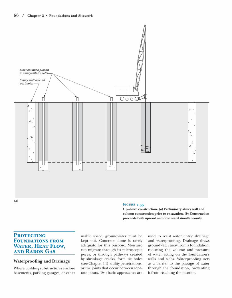
66 / Chapter 2 Foundations and Sitework
Figure 2.55Up–down construction. (a) Preliminary slurry wall and column construction prior to excavation. (b) Construction proceeds both upward and downward simultaneously.
Steel columns placedin slurry-filled shafts
Slurry wall aroundperimeter
(a)
Protecting Foundations from Water, Heat Flow, and Radon Gas
Waterproofing and Drainage
Where building substructures enclose
basements, parking garages, or other
usable space, groundwater must be
kept out. Concrete alone is rarely
adequate for this purpose. Moisture
can migrate through its microscopic
pores, or through pathways created
by shrinkage cracks, form tie holes
(see Chapter 14), utility penetrations,
or the joints that occur between sepa-
rate pours. Two basic approaches are
used to resist water entry: drainage
and waterproofing. Drainage draws
groundwater away from a foundation,
reducing the volume and pressure
of water acting on the foundation’s
walls and slabs. Waterproofing acts
as a barrier to the passage of water
through the foundation, preventing
it from reaching the interior.
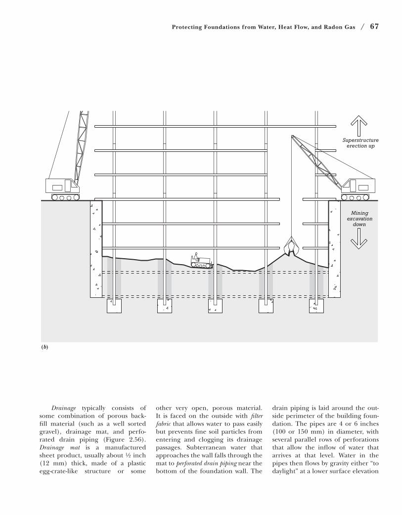
Protecting Foundations from Water, Heat Flow, and Radon Gas / 67
drain piping is laid around the out-
side perimeter of the building foun-
dation. The pipes are 4 or 6 inches
(100 or 150 mm) in diameter, with
several parallel rows of perforations
that allow the inflow of water that
arrives at that level. Water in the
pipes then flows by gravity either “to
daylight” at a lower surface elevation
other very open, porous material.
It is faced on the outside with filter fabric that allows water to pass easily
but prevents fine soil particles from
entering and clogging its drainage
passages. Subterranean water that
approaches the wall falls through the
mat to perforated drain piping near the
bottom of the foundation wall. The
Superstructureerection up
Miningexcavation
down
(b)
Drainage typically consists of
some combination of porous back-
fill material (such as a well sorted
gravel), drainage mat, and perfo-
rated drain piping (Figure 2.56).
Drainage mat is a manufactured
sheet product, usually about ½ inch
(12 mm) thick, made of a plastic
egg-crate-like structure or some
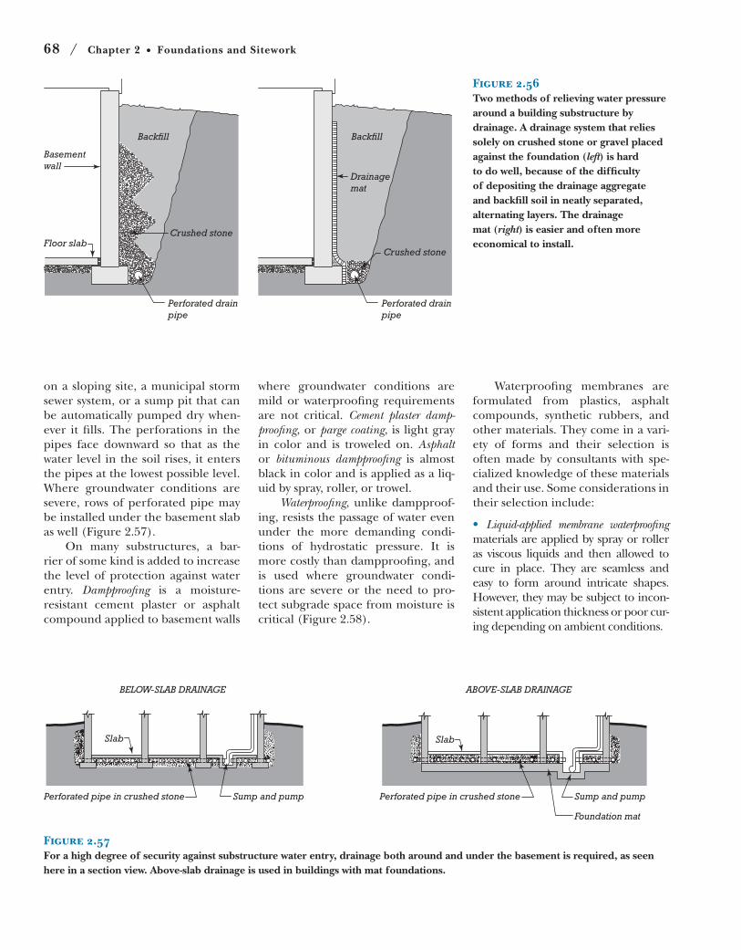
68 / Chapter 2 Foundations and Sitework
Figure 2.57For a high degree of security against substructure water entry, drainage both around and under the basement is required, as seen here in a section view. Above-slab drainage is used in buildings with mat foundations.
BELOW-SLAB DRAINAGE
Perforated pipe in crushed stone Sump and pump
Slab
ABOVE-SLAB DRAINAGE
Perforated pipe in crushed stone Sump and pump
Foundation mat
Slab
Perforated drainpipe
Basementwall
Floor slab
Backfill
Crushed stone
Perforated drainpipe
Backfill
Crushed stone
Drainage mat
Figure 2.56Two methods of relieving water pressure around a building substructure by drainage. A drainage system that relies solely on crushed stone or gravel placed against the foundation (left) is hard to do well, because of the difficulty of depositing the drainage aggregate and backfill soil in neatly separated, alternating layers. The drainage mat (right) is easier and often more economical to install.
on a sloping site, a municipal storm
sewer system, or a sump pit that can
be automatically pumped dry when-
ever it fills. The perforations in the
pipes face downward so that as the
water level in the soil rises, it enters
the pipes at the lowest possible level.
Where groundwater conditions are
severe, rows of perforated pipe may
be installed under the basement slab
as well (Figure 2.57).
On many substructures, a bar-
rier of some kind is added to increase
the level of protection against water
entry. Dampproofing is a moisture-
resistant cement plaster or asphalt
compound applied to basement walls
where groundwater conditions are
mild or waterproofing requirements
are not critical. Cement plaster damp-proofing, or parge coating, is light gray
in color and is troweled on. Asphalt or bituminous dampproofing is almost
black in color and is applied as a liq-
uid by spray, roller, or trowel.
Waterproofing, unlike dampproof-
ing, resists the passage of water even
under the more demanding condi-
tions of hydrostatic pressure. It is
more costly than dampproofing, and
is used where groundwater condi-
tions are severe or the need to pro-
tect subgrade space from moisture is
critical (Figure 2.58).
Waterproofing membranes are
formulated from plastics, asphalt
compounds, synthetic rubbers, and
other materials. They come in a vari-
ety of forms and their selection is
often made by consultants with spe-
cialized knowledge of these materials
and their use. Some considerations in
their selection include:
Liquid-applied membrane waterproofing
materials are applied by spray or roller
as viscous liquids and then allowed to
cure in place. They are seamless and
easy to form around intricate shapes.
However, they may be subject to incon-
sistent application thickness or poor cur-
ing depending on ambient conditions.
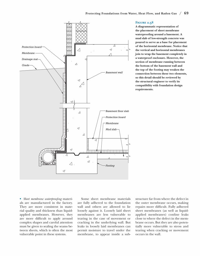
Protecting Foundations from Water, Heat Flow, and Radon Gas / 69
Figure 2.58A diagrammatic representation of the placement of sheet membrane waterproofing around a basement. A mud slab of low-strength concrete was poured to serve as a base for placement of the horizontal membrane. Notice that the vertical and horizontal membranes join to wrap the basement completely in a waterproof enclosure. However, the section of membrane running between the bottom of the basement wall and the top of the footing may weaken the connection between these two elements, so this detail should be reviewed by the structural engineer to verify its compatibility with foundation design requirements.
Protection board
Membrane
Drainage mat
Grade
Basement �oor slab
Protection board
Membrane
Mud slab
Basement wall
Footing
• Sheet membrane waterproofingmateri-als are manufactured in the factory.They are more consistent in mate-rialqualityandthicknessthanliquid-applied membranes. However, theyare more difficult to apply aroundcomplexshapesandcarefulattentionmustbegiventosealingtheseamsbe-tweensheets,whichisoftenthemostvulnerablepointinthesesystems.
Some sheet membrane materialsare fully adhered to the foundationwall and others are allowed to lieloosely against it. Loosely laid sheetmembranes are less vulnerable totearing in the case ofmovement orcracking in theunderlyingwall.Butleaks in loosely laidmembranes canpermitmoisture to travel under themembrane, to appear inside a sub-
structurefarfromwherethedefectintheoutermembraneoccurs,makingrepairsmoredifficult.Fullyadheredsheetmembranes (as well as liquid-applied membranes) confine leaksclosetowherethedefectinthemem-braneoccurs.Buttheyarealsopoten-tially more vulnerable to stress andtearingwhencrackingormovementoccursinthewall.
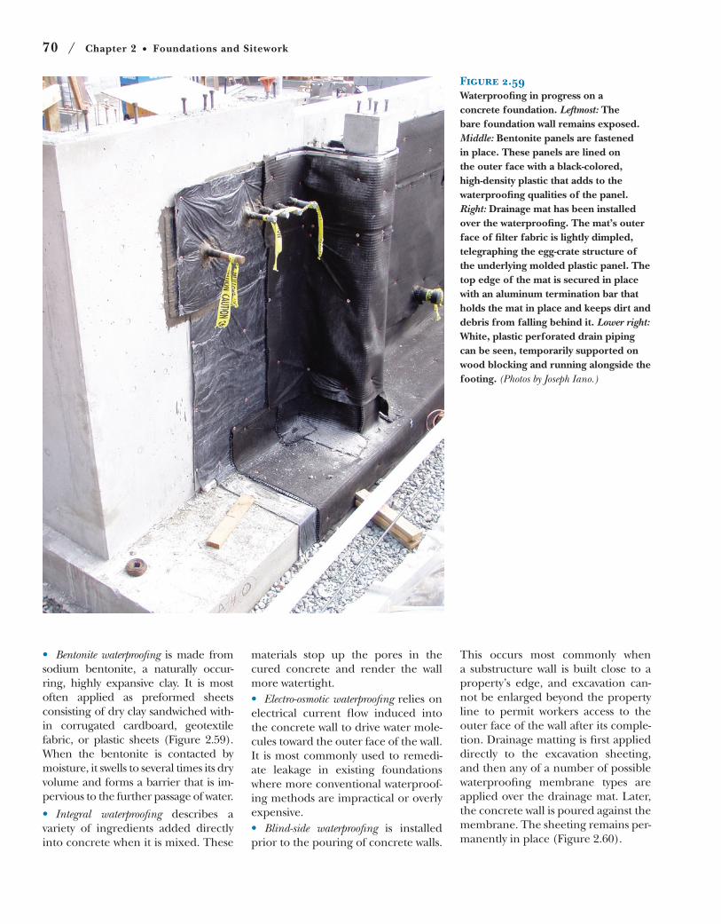
70 / Chapter 2 Foundations and Sitework
Figure 2.59Waterproofing in progress on a concrete foundation. Leftmost: The bare foundation wall remains exposed. Middle: Bentonite panels are fastened in place. These panels are lined on the outer face with a black-colored, high-density plastic that adds to the waterproofing qualities of the panel. Right: Drainage mat has been installed over the waterproofing. The mat’s outer face of filter fabric is lightly dimpled, telegraphing the egg-crate structure of the underlying molded plastic panel. The top edge of the mat is secured in place with an aluminum termination bar that holds the mat in place and keeps dirt and debris from falling behind it. Lower right: White, plastic perforated drain piping can be seen, temporarily supported on wood blocking and running alongside the footing. (Photos by Joseph Iano.)
Bentonite waterproofing is made from
sodium bentonite, a naturally occur-
ring, highly expansive clay. It is most
often applied as preformed sheets
consisting of dry clay sandwiched with-
in corrugated cardboard, geotextile
fabric, or plastic sheets (Figure 2.59).
When the bentonite is contacted by
moisture, it swells to several times its dry
volume and forms a barrier that is im-
pervious to the further passage of water.
Integral waterproofing describes a
variety of ingredients added directly
into concrete when it is mixed. These
materials stop up the pores in the
cured concrete and render the wall
more watertight.
Electro-osmotic waterproofing relies on
electrical current flow induced into
the concrete wall to drive water mole-
cules toward the outer face of the wall.
It is most commonly used to remedi-
ate leakage in existing foundations
where more conventional waterproof-
ing methods are impractical or overly
expensive.
Blind-side waterproofing is installed
prior to the pouring of concrete walls.
This occurs most commonly when
a substructure wall is built close to a
property’s edge, and excavation can-
not be enlarged beyond the property
line to permit workers access to the
outer face of the wall after its comple-
tion. Drainage matting is first applied
directly to the excavation sheeting,
and then any of a number of possible
waterproofing membrane types are
applied over the drainage mat. Later,
the concrete wall is poured against the
membrane. The sheeting remains per-
manently in place (Figure 2.60).
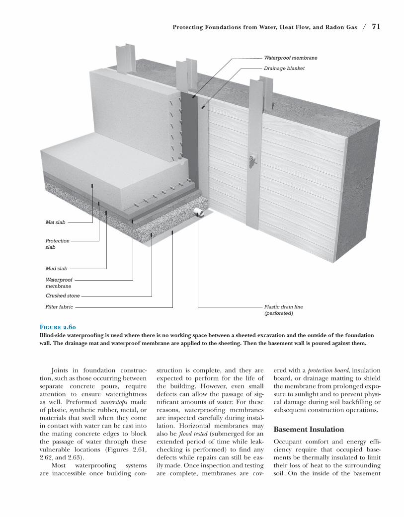
Protecting Foundations from Water, Heat Flow, and Radon Gas / 71
Figure 2.60Blind-side waterproofing is used where there is no working space between a sheeted excavation and the outside of the foundation wall. The drainage mat and waterproof membrane are applied to the sheeting. Then the basement wall is poured against them.
Waterproof membrane
Drainage blanket
Plastic drain line(perforated)
Mat slab
Protectionslab
Mud slab
Waterproofmembrane
Crushed stone
Filter fabric
Joints in foundation construc-
tion, such as those occurring between
separate concrete pours, require
attention to ensure watertightness
as well. Preformed waterstops made
of plastic, synthetic rubber, metal, or
materials that swell when they come
in contact with water can be cast into
the mating concrete edges to block
the passage of water through these
vulnerable locations (Figures 2.61,
2.62, and 2.63).
Most waterproofing systems
are inaccessible once building con-
struction is complete, and they are
expected to perform for the life of
the building. However, even small
defects can allow the passage of sig-
nificant amounts of water. For these
reasons, waterproofing membranes
are inspected carefully during instal-
lation. Horizontal membranes may
also be flood tested (submerged for an
extended period of time while leak-
checking is performed) to find any
defects while repairs can still be eas-
ily made. Once inspection and testing
are complete, membranes are cov-
ered with a protection board, insulation
board, or drainage matting to shield
the membrane from prolonged expo-
sure to sunlight and to prevent physi-
cal damage during soil backfilling or
subsequent construction operations.
Basement Insulation
Occupant comfort and energy effi-
ciency require that occupied base-
ments be thermally insulated to limit
their loss of heat to the surrounding
soil. On the inside of the basement
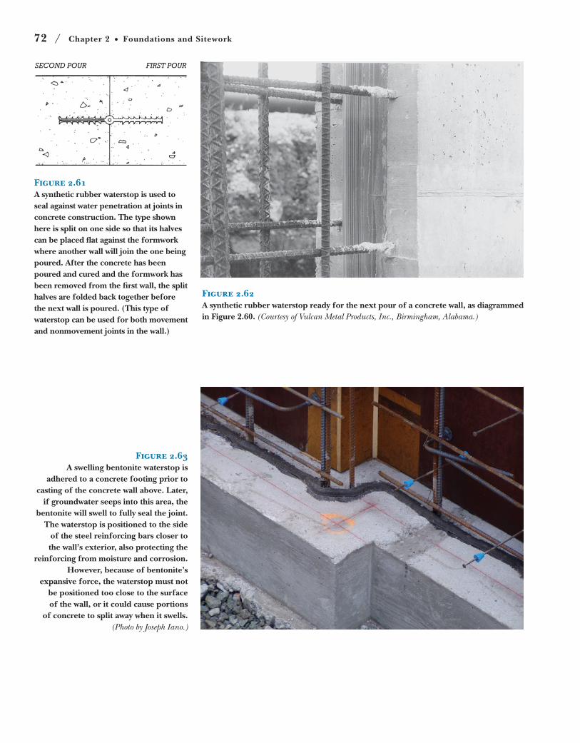
72 / Chapter 2 Foundations and Sitework
SECOND POUR FIRST POUR
Figure 2.61A synthetic rubber waterstop is used to seal against water penetration at joints in concrete construction. The type shown here is split on one side so that its halves can be placed flat against the formwork where another wall will join the one being poured. After the concrete has been poured and cured and the formwork has been removed from the first wall, the split halves are folded back together before the next wall is poured. (This type of waterstop can be used for both movement and nonmovement joints in the wall.)
Figure 2.62A synthetic rubber waterstop ready for the next pour of a concrete wall, as diagrammed in Figure 2.60. (Courtesy of Vulcan Metal Products, Inc., Birmingham, Alabama.)
Figure 2.63A swelling bentonite waterstop is
adhered to a concrete footing prior to casting of the concrete wall above. Later,
if groundwater seeps into this area, the bentonite will swell to fully seal the joint.
The waterstop is positioned to the side of the steel reinforcing bars closer to the wall’s exterior, also protecting the
reinforcing from moisture and corrosion. However, because of bentonite’s
expansive force, the waterstop must not be positioned too close to the surface of the wall, or it could cause portions
of concrete to split away when it swells. (Photo by Joseph Iano.)
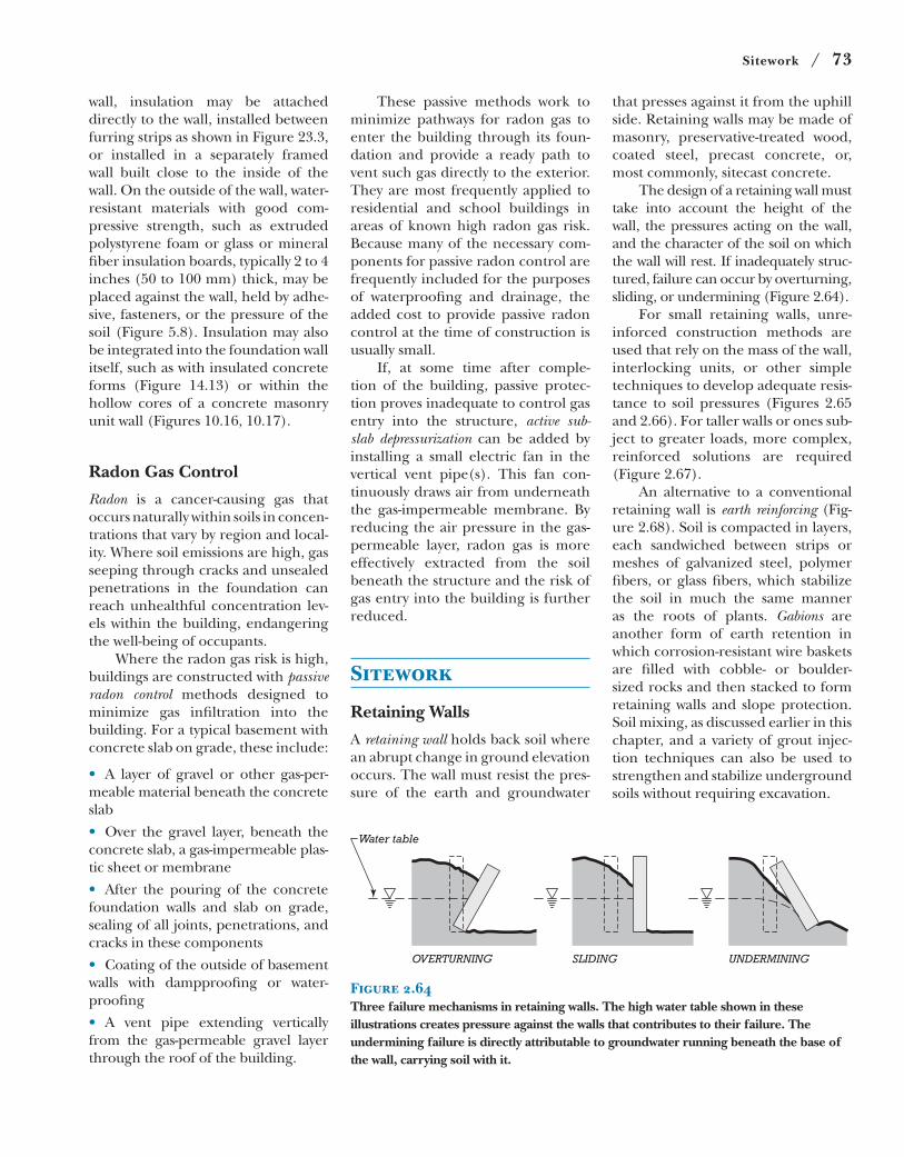
Sitework / 73
that presses against it from the uphill
side. Retaining walls may be made of
masonry, preservative-treated wood,
coated steel, precast concrete, or,
most commonly, sitecast concrete.
The design of a retaining wall must
take into account the height of the
wall, the pressures acting on the wall,
and the character of the soil on which
the wall will rest. If inadequately struc-
tured, failure can occur by overturning,
sliding, or undermining (Figure 2.64).
For small retaining walls, unre-
inforced construction methods are
used that rely on the mass of the wall,
interlocking units, or other simple
techniques to develop adequate resis-
tance to soil pressures (Figures 2.65
and 2.66). For taller walls or ones sub-
ject to greater loads, more complex,
reinforced solutions are required
(Figure 2.67).
An alternative to a conventional
retaining wall is earth reinforcing (Fig-
ure 2.68). Soil is compacted in layers,
each sandwiched between strips or
meshes of galvanized steel, polymer
fibers, or glass fibers, which stabilize
the soil in much the same manner
as the roots of plants. Gabions are
another form of earth retention in
which corrosion-resistant wire baskets
are filled with cobble- or boulder-
sized rocks and then stacked to form
retaining walls and slope protection.
Soil mixing, as discussed earlier in this
chapter, and a variety of grout injec-
tion techniques can also be used to
strengthen and stabilize underground
soils without requiring excavation.
These passive methods work to
minimize pathways for radon gas to
enter the building through its foun-
dation and provide a ready path to
vent such gas directly to the exterior.
They are most frequently applied to
residential and school buildings in
areas of known high radon gas risk.
Because many of the necessary com-
ponents for passive radon control are
frequently included for the purposes
of waterproofing and drainage, the
added cost to provide passive radon
control at the time of construction is
usually small.
If, at some time after comple-
tion of the building, passive protec-
tion proves inadequate to control gas
entry into the structure, active sub-slab depressurization can be added by
installing a small electric fan in the
vertical vent pipe(s). This fan con-
tinuously draws air from underneath
the gas-impermeable membrane. By
reducing the air pressure in the gas-
permeable layer, radon gas is more
effectively extracted from the soil
beneath the structure and the risk of
gas entry into the building is further
reduced.
Sitework
Retaining Walls
A retaining wall holds back soil where
an abrupt change in ground elevation
occurs. The wall must resist the pres-
sure of the earth and groundwater
wall, insulation may be attached
directly to the wall, installed between
furring strips as shown in Figure 23.3,
or installed in a separately framed
wall built close to the inside of the
wall. On the outside of the wall, water-
resistant materials with good com-
pressive strength, such as extruded
polystyrene foam or glass or mineral
fiber insulation boards, typically 2 to 4
inches (50 to 100 mm) thick, may be
placed against the wall, held by adhe-
sive, fasteners, or the pressure of the
soil (Figure 5.8). Insulation may also
be integrated into the foundation wall
itself, such as with insulated concrete
forms (Figure 14.13) or within the
hollow cores of a concrete masonry
unit wall (Figures 10.16, 10.17).
Radon Gas Control
Radon is a cancer-causing gas that
occurs naturally within soils in concen-
trations that vary by region and local-
ity. Where soil emissions are high, gas
seeping through cracks and unsealed
penetrations in the foundation can
reach unhealthful concentration lev-
els within the building, endangering
the well-being of occupants.
Where the radon gas risk is high,
buildings are constructed with passive radon control methods designed to
minimize gas infiltration into the
building. For a typical basement with
concrete slab on grade, these include:
A layer of gravel or other gas-per-
meable material beneath the concrete
slab
Over the gravel layer, beneath the
concrete slab, a gas-impermeable plas-
tic sheet or membrane
After the pouring of the concrete
foundation walls and slab on grade,
sealing of all joints, penetrations, and
cracks in these components
Coating of the outside of basement
walls with dampproofing or water-
proofing
A vent pipe extending vertically
from the gas-permeable gravel layer
through the roof of the building.
OVERTURNING
Water table
SLIDING UNDERMINING
Figure 2.64Three failure mechanisms in retaining walls. The high water table shown in these illustrations creates pressure against the walls that contributes to their failure. The undermining failure is directly attributable to groundwater running beneath the base of the wall, carrying soil with it.
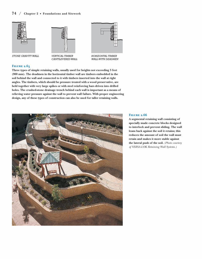
74 / Chapter 2 Foundations and Sitework
Figure 2.66A segmental retaining wall consisting of specially made concrete blocks designed to interlock and prevent sliding. The wall leans back against the soil it retains; this reduces the amount of soil the wall must retain and makes it more stable against the lateral push of the soil. (Photo courtesy of VERSA-LOK Retaining Wall Systems.)
STONE GRAVITY WALL VERTICAL TIMBERCANTILEVERED WALL
HORIZONTAL TIMBERWALL WITH DEADMEN
Figure 2.65Three types of simple retaining walls, usually used for heights not exceeding 3 feet (900 mm). The deadmen in the horizontal timber wall are timbers embedded in the soil behind the wall and connected to it with timbers inserted into the wall at right angles. The timbers, which should be pressure treated with a wood preservative, are held together with very large spikes or with steel reinforcing bars driven into drilled holes. The crushed-stone drainage trench behind each wall is important as a means of relieving water pressure against the wall to prevent wall failure. With proper engineering design, any of these types of construction can also be used for taller retaining walls.
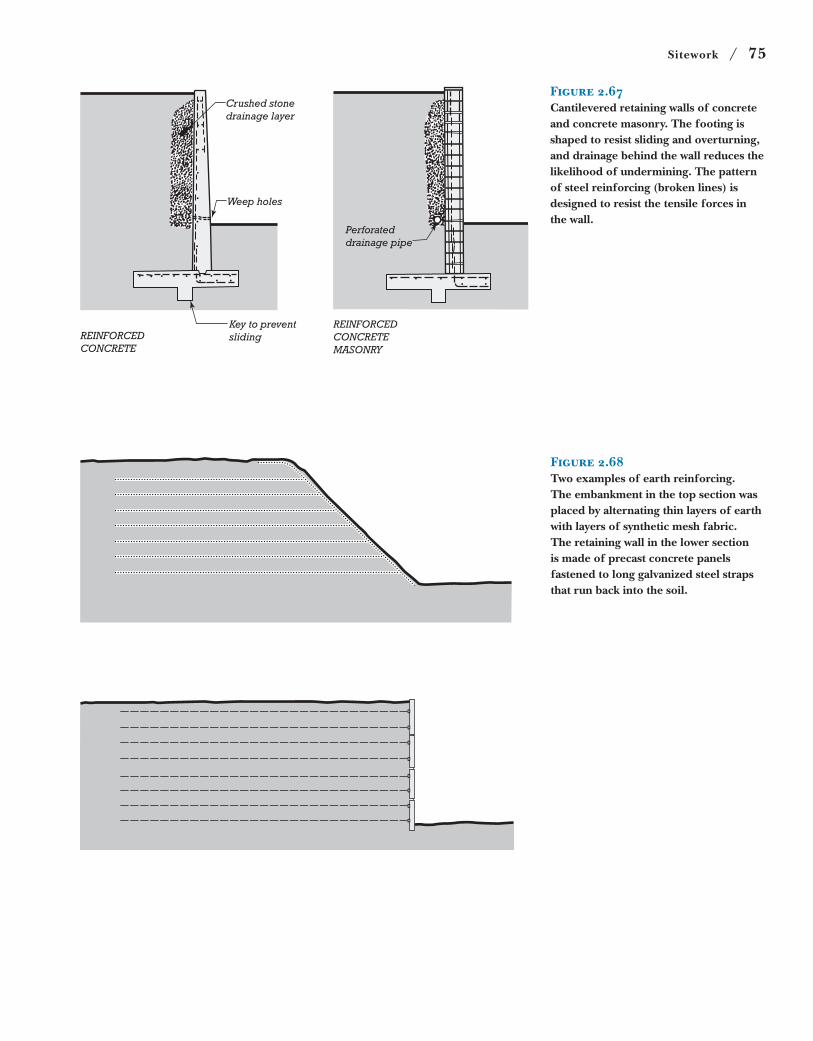
Sitework / 75
Crushed stonedrainage layer
Weep holes
REINFORCEDCONCRETE
Key to preventsliding
REINFORCEDCONCRETEMASONRY
Perforateddrainage pipe
Figure 2.67Cantilevered retaining walls of concrete and concrete masonry. The footing is shaped to resist sliding and overturning, and drainage behind the wall reduces the likelihood of undermining. The pattern of steel reinforcing (broken lines) is designed to resist the tensile forces in the wall.
Figure 2.68Two examples of earth reinforcing. The embankment in the top section was placed by alternating thin layers of earth with layers of synthetic mesh fabric. The retaining wall in the lower section is made of precast concrete panels fastened to long galvanized steel straps that run back into the soil.
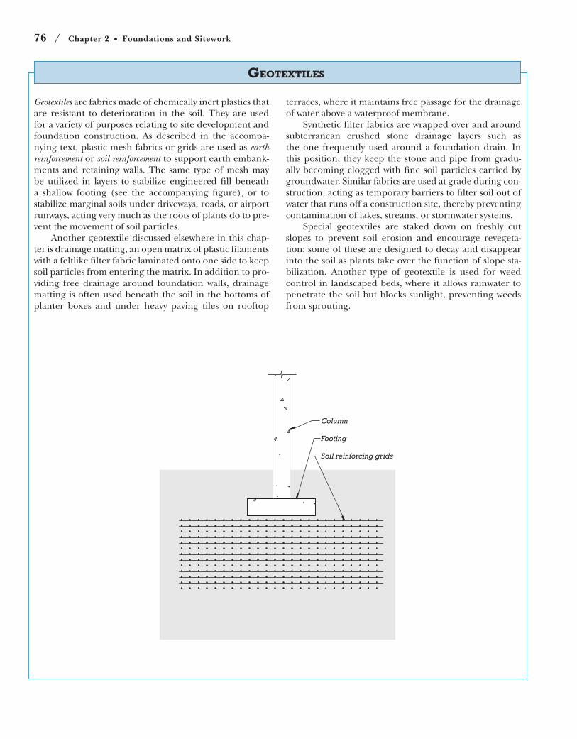
76 / Chapter 2 Foundations and Sitework
Geotextiles are fabrics made of chemically inert plastics that
are resistant to deterioration in the soil. They are used
for a variety of purposes relating to site development and
foundation construction. As described in the accompa-
nying text, plastic mesh fabrics or grids are used as earth reinforcement or soil reinforcement to support earth embank-
ments and retaining walls. The same type of mesh may
be utilized in layers to stabilize engineered fill beneath
a shallow footing (see the accompanying figure), or to
stabilize marginal soils under driveways, roads, or airport
runways, acting very much as the roots of plants do to pre-
vent the movement of soil particles.
Another geotextile discussed elsewhere in this chap-
ter is drainage matting, an open matrix of plastic filaments
with a feltlike filter fabric laminated onto one side to keep
soil particles from entering the matrix. In addition to pro-
viding free drainage around foundation walls, drainage
matting is often used beneath the soil in the bottoms of
planter boxes and under heavy paving tiles on rooftop
terraces, where it maintains free passage for the drainage
of water above a waterproof membrane.
Synthetic filter fabrics are wrapped over and around
subterranean crushed stone drainage layers such as
the one frequently used around a foundation drain. In
this position, they keep the stone and pipe from gradu-
ally becoming clogged with fine soil particles carried by
groundwater. Similar fabrics are used at grade during con-
struction, acting as temporary barriers to filter soil out of
water that runs off a construction site, thereby preventing
contamination of lakes, streams, or stormwater systems.
Special geotextiles are staked down on freshly cut
slopes to prevent soil erosion and encourage revegeta-
tion; some of these are designed to decay and disappear
into the soil as plants take over the function of slope sta-
bilization. Another type of geotextile is used for weed
control in landscaped beds, where it allows rainwater to
penetrate the soil but blocks sunlight, preventing weeds
from sprouting.
GEOTEXTILES
Column
Footing
Soil reinforcing grids
Designing Foundations / 77
more expensive efforts will be needed
to dewater the site, strengthen excava-
tion support systems, waterproof the
foundation, and protect the finished
foundation against permanent hydro-
static pressures.
Building close to an existing structure. If the excavation can be kept well away
from adjacent structures, the founda-
tions of these structures will remain
undisturbed and no effort or special
expense will be required to protect
them. When digging close to an ex-
isting structure, and especially when
digging deeper than that structure’s
foundations, temporary bracing or
permanent underpinning may be re-
quired to prevent disturbance.
Increasing the column or wall load from a building beyond what can be supported by a shallow foundation. Shallow founda-
tions are far less expensive than piles
or caissons under most conditions.
If the building grows too high, or is
structured so that individual column
loads are too high, a shallow founda-
tion may no longer be able to carry
the load and a more expensive, deep
foundation system may be required.
For one- and two-family dwell-
ings, foundation design is usually
much simpler than for larger build-
ings, because foundation loadings
are low. The uncertainties in foun-
dation design can be reduced with
reasonable economy by adopting
a large factor of safety in calculat-
ing the bearing capacity of the soil.
Unless the designer has reason to
suspect poor soil conditions, the
footings are usually designed using
rule-of-thumb allowable soil stresses
and standardized footing dimen-
sions. The designer then examines
the actual soil when the excavations
have been made. If it is not of the
quality that was expected, the foot-
ings can be hastily redesigned using a
revised estimate of soil-bearing capac-
ity before construction continues. If
unexpected groundwater is encoun-
tered, better drainage may have to be
provided around the foundation or
the depth of the basement decreased.
and/or fly ash (a byproduct of coal-
burning power plants), sand, and
water. CLSM, sometimes called “flow-
able fill,” is delivered in concrete
mixer trucks and poured into the
excavation, where it compacts and
levels itself, then hardens. CLSM
may be used to pour mud slabs, which
are weak concrete slabs used to cre-
ate temporary, level, dry bases over
irregular, often wet excavations. Such
a temporary slab can serve as a work-
ing surface for the installation of
reinforcing and pouring of a foun-
dation mat or basement floor slab. It
can also serve as a surface to which a
waterproofing membrane is applied.
CLSM may be used to replace pock-
ets of unstable soil encountered
beneath a substructure or to backfill
around basement walls. The strength
of CLSM is matched to the situation.
For example, for a utility trench,
CLSM is formulated so that it is weak
enough to be excavated easily by
ordinary digging equipment when
the pipe requires servicing, yet is as
strong as a normal, good-quality com-
pacted backfill.
Finish grading refers to the final
leveling and smoothing of soil sur-
faces to their required contours and
elevations. Where plant materials are
planned, finish grading includes the
application of nutrient-rich, organic
topsoil to depths suitable for support-
ing the growth of the types of grass,
plants, shrubs, or trees that have been
specified by the landscape architect.
Designing Foundations
In foundation design, there are
thresholds that, when crossed, cause
significant, sudden increases in con-
struction costs:
Building below the water table. If the
substructure and foundations of a
building are above the water table,
minimal effort will be required to keep
the excavation dry during construc-
tion. Once the water table is reached,
Filling and Finish Grading
Filling refers broadly to any placing of
earth material (for example, to raise
an existing grade), whereas backfilling refers more specifically to the replace-
ment of soil materials in an excava-
tion to restore it close to its finished
level. Backfilling occurs around foun-
dations and substructures, in utility
trenches, and behind retaining walls.
For any type of filling, an appropri-
ate type of replacement soil is added in
layers, or lifts, which may range from 4
inches to roughly a foot (100 to 300
mm) in depth. Each lift is compacted
before the next is added. Compaction
may be performed by heavy rolling,
vibrating, or ramming, depending on
soil type and depth of lift. Small, walk-
behind machines are used in confined
areas, and bigger, driven machinery is
used over larger areas.
To achieve optimal compaction
and minimize future settlement, fill
material must be moist enough to
readily compress into a dense par-
ticle arrangement, but not so wet
as to become unstable or soupy.
Where backfill material will support
slabs, pavements, or foundations, its
strength and settlement properties
are critical, and the soil materials,
moisture content, and compaction
work are all monitored by on-site
engineers to ensure that the required
performance will be achieved.
Around foundations, water-
proofing, insulation, and drainage
components must be in place before
backfilling can begin. In addition,
sufficient internal structure must be
constructed to provide bracing for
the foundation wall, so that the wall
can resist the lateral loading from the
backfilled soil. For example, in resi-
dential construction, the first-floor
platform must completed before
foundation backfilling occurs, as this
floor structure acts to laterally brace
the top of the foundation wall (Fig-
ure 5.7).
Controlled low-strength material (CLSM) is a manufactured fill mate-
rial made from portland cement
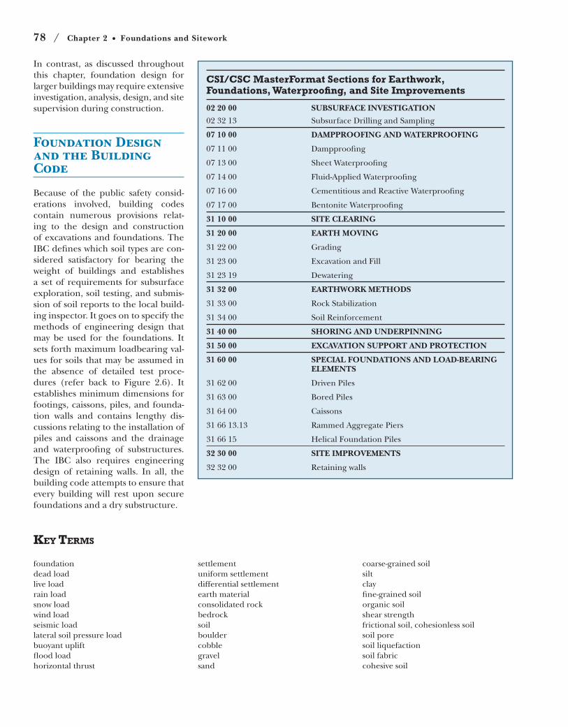
78 / Chapter 2 Foundations and Sitework
CSI/CSC MasterFormat Sections for Earthwork, Foundations, Waterproofing, and Site Improvements
02 20 00 SUBSURFACE INVESTIGATION
02 32 13 Subsurface Drilling and Sampling
07 10 00 DAMPPROOFING AND WATERPROOFING
07 11 00 Dampproofing
07 13 00 Sheet Waterproofing
07 14 00 Fluid-Applied Waterproofing
07 16 00 Cementitious and Reactive Waterproofing
07 17 00 Bentonite Waterproofing
31 10 00 SITE CLEARING
31 20 00 EARTH MOVING
31 22 00 Grading
31 23 00 Excavation and Fill
31 23 19 Dewatering
31 32 00 EARTHWORK METHODS
31 33 00 Rock Stabilization
31 34 00 Soil Reinforcement
31 40 00 SHORING AND UNDERPINNING
31 50 00 EXCAVATION SUPPORT AND PROTECTION
31 60 00 SPECIAL FOUNDATIONS AND LOAD-BEARING ELEMENTS
31 62 00 Driven Piles
31 63 00 Bored Piles
31 64 00 Caissons
31 66 13.13 Rammed Aggregate Piers
31 66 15 Helical Foundation Piles
32 30 00 SITE IMPROVEMENTS
32 32 00 Retaining walls
KEY TERMS
foundation
dead load
live load
rain load
snow load
wind load
seismic load
lateral soil pressure load
buoyant uplift
flood load
horizontal thrust
settlement
uniform settlement
differential settlement
earth material
consolidated rock
bedrock
soil
boulder
cobble
gravel
sand
coarse-grained soil
silt
clay
fine-grained soil
organic soil
shear strength
frictional soil, cohesionless soil
soil pore
soil liquefaction
soil fabric
cohesive soil
In contrast, as discussed throughout
this chapter, foundation design for
larger buildings may require extensive
investigation, analysis, design, and site
supervision during construction.
Foundation Design and the Building Code
Because of the public safety consid-
erations involved, building codes
contain numerous provisions relat-
ing to the design and construction
of excavations and foundations. The
IBC defines which soil types are con-
sidered satisfactory for bearing the
weight of buildings and establishes
a set of requirements for subsurface
exploration, soil testing, and submis-
sion of soil reports to the local build-
ing inspector. It goes on to specify the
methods of engineering design that
may be used for the foundations. It
sets forth maximum loadbearing val-
ues for soils that may be assumed in
the absence of detailed test proce-
dures (refer back to Figure 2.6). It
establishes minimum dimensions for
footings, caissons, piles, and founda-
tion walls and contains lengthy dis-
cussions relating to the installation of
piles and caissons and the drainage
and waterproofing of substructures.
The IBC also requires engineering
design of retaining walls. In all, the
building code attempts to ensure that
every building will rest upon secure
foundations and a dry substructure.
Review Questions / 79
plastic soil
liquid limit
expansive soil
gradation
well graded soil
poorly graded soil
uniformly graded soil
gap graded soil
sorting
poorly sorted soil
well sorted soil
allowable foundation pressure
allowable soil pressure
consolidation
imported soil
native soil
general purpose fill
drainage fill
test pit
water table
test boring
penetration sampler
load test
sieve
plastic limit
geotechnical report
brownfield site
earthwork
grubbing and clearing
excavation
benched excavation
maximum allowable slope, angle of
repose
excavation support
shoring
H-pile
soldier beam
lagging
sheet piling, sheeting
pneumatically applied concrete,
shotcrete
soil mixing
ground improvement, earth
improvement
slurry wall
clamshell bucket
slurry
tremie
crosslot bracing
waler
raker
tieback
rock anchor
soil nailing
dewatering
sump
well point
watertight barrier wall
soil freezing
superstructure
substructure
shallow foundation
deep foundation
spread footing
column footing
wall footing, strip footing
engineered fill
frost line
ice lens
slab on grade
crawlspace
basement
tie beam
combined footing
cantilever footing
shallow frost-protected foundation
mat foundation, raft foundation
floating foundation, compensated
foundation
caisson, drilled pier
belling
auger drill
belling bucket
belled caisson
socketed caisson
pile
end bearing pile
friction pile
pile cap
driven to refusal
grade beam
pile hammer
piledriver lead
piledriver
timber pile
heaving
pipe pile
minipile, pin pile, micropile
helical pile, screw pile
precast concrete pile
sitecast concrete pile
pressure-injected footing
compaction grouted footing
rammed aggregate pier, stone column
base isolator
underpinning
up–down construction
drainage
drainage mat
filter fabric
perforated drain piping
dampproofing
cement plaster dampproofing, parge
coating
asphalt dampproofing, bituminous
dampproofing
waterproofing
liquid-applied membrane
waterproofing
sheet membrane waterproofing
bentonite waterproofing
integral waterproofing
electro-osmotic waterproofing
blind-side waterproofing
waterstop
flood test
protection board
radon (gas)
passive radon control
active subslab depressurization
retaining wall
earth reinforcing
gabion
geotextile
earth reinforcement, soil reinforcement
filling
backfilling
soil lift
controlled low-strength material (CLSM)
mud slab
finish grading
REVIEW QUESTIONS
1. What is the nature of the most com-
mon type of foundation failure? What are
its causes?
2. Explain the differences among sand,
silt, and clay, both in their physical char-
acteristics and their behavior in relation
to building foundations.
3. Explain the difference between a cohe-
sionless soil and a cohesive soil. Give one
example of each soil type.
4. Explain the difference between well
graded and poorly graded soil. How does
their behavior differ?
5. What is a test soil boring and why is it
performed?
6. What is excavation sheeting used for?
List three different types of excavation
sheeting.
80 / Chapter 2 Foundations and Sitework
7. Under what conditions would you use
a watertight barrier instead of well points
when digging below the water table?
8. In cold climates, how does the frost line
affect the placement of shallow footings?
What footing type is an exception to this
general principle?
9. What conditions might lead to the
choice of a mat foundation for a build-
ing?
10. If shallow foundations are substantial-
ly less costly than deep foundations, why
do we use deep foundations?
11. What soil conditions favor piles over
caissons? What type of pile is especially
well suited to repair or improvement of
existing foundations and why?
12. List and explain some cost thresholds
frequently encountered in foundation
design.
13. Explain the difference between water-
proofing and dampproofing. When is one
or the other an appropriate choice for
protecting a foundation from moisture?
14. List two types of waterproofing and
describe one possible advantage of each.
15. List the components of a typical foun-
dation drainage system and their func-
tions.
16. What is filling? Why is fill placed in
lifts?
fully the arrangements made for excava-
tion support and dewatering. How is the
soil being loosened and carried away?
What is being done with the excavated
soil? What type of foundation is being in-
stalled? What provisions are being made
to keep the substructure permanently
dry?
the foundation drawings. What type was
actually used? Can you explain why?
2. What types of foundation and substruc-
ture are normally used for houses in your
area? Why?
3. Look at several excavations for major
buildings under construction. Note care-
EXERCISES
1. Obtain the foundation drawings and
soils report for a nearby building. Look
first at the log of test borings. What sorts
of soils were found beneath the site? How
deep is the water table? What types of
foundations do you think might be suit-
able for use in this situation? Now look at
SELECTED REFERENCES
Ambrose, James E. Simplified Design of Building Foundations (2nd ed.). Hoboken,
NJ, John Wiley & Sons, Inc., 1998.
Discusses soil properties and provides
simplified computation procedures for
both shallow and deep foundations.
Cheng, Liu, and Jack Evett. Soils and Foun-dations (7th ed.). Upper Saddle River, NJ,
Prentice Hall, Inc., 2008.
Provides detailed discussion of the engi-
neering properties of soils, subsurface ex-
ploration techniques, soil mechanics, and
shallow and deep foundations.
Kubal, Michael. Construction Waterproofing Handbook (2nd ed). New York, McGraw-
Hill, 2008.
Covers all aspects of building waterproof-
ing, both above and below grade.
National Roofing Contractors Associa-
tion. The NRCA Waterproofing Manual. Rosemont, IL, updated regularly.
Provides industry-standard guidelines
and details for the application of water-
proofing and dampproofing to building
substructures.
Web Sites / 81
WEB SITES
Foundations
Author’s supplementary web site: www.ianosbackfill.com/02_foundations/
Whole Building Design Guide, Foundation Walls: www.wbdg.org/design/env_bg_wall.php
Earth Retention and Deep Foundations
Case Foundation Company: www.casefoundation.com
Geopier Foundation: www.geopier.com
Hayward Baker Geotechnical Construction: www.haywardbaker.com
Nicholson Construction Company: www.nicholsonconstruction.com
Schnabel Foundation Company: www.schnabel.com
Waterproofing
CETCO Building Materials Group: buildingmaterials.cetco.com
Grace Construction Products: www.na.graceconstruction.com