Embed Size (px)
Citation preview

1
A MESSAGE FROMRANGER FOUNDER, FORREST WOOD
Congratulations! You and your newRanger are part of a celebrated heritageand legacy of leadership spanningnearly four decades. We appreciatethe confidence you’ve shown us byselecting Ranger as your boat ofchoice. Since our very beginnings,we’ve worked hard to continually earn
your trust by making quality, innovation,and attention to detail our constant
watchwords. As the owner of a newRanger boat, you’re eligible for a world of
benefits from the Ranger Owner’s Group.Drop us a line or visit our website atrangerboats.com for more details. It’s justone more way we’d like to say ‘thank you’while sharing even more great opportunitieswith our family.
We encourage you to make safety and courteous boating practices an integral part ofyour outdoor activities. “Boat Smart From The Start.” Take a boating education courseand get a vessel safety check for your boat. For more information on these importantservices, contact the United States Coast Guard Auxiliary at 1-800-368-5647,www.cgaux.org, or the United States Power Squadrons at 888-FOR-USPS,www.usps.org. Remember that common sense and sound judgement are two of themost important elements to carry with you on every outing.
If we can be of additional help, feel free to give us a call, visit us on the internet, contactyour local dealer, or just drop us a line through the mail. Thank you, again, for being apart of the legendary “Ranger Family!”
This manual is intended to help you better understand your boat and make basic careand maintenance quite simple. Additionally, it provides important information essentialfor safe and pleasant boat operation. Please take the time to study this manual alongwith your engine and equipment manuals before operating your boat. Should you havequestions, visit with your Ranger dealer or contact us at… Ranger® Boats • P.O. Box179 • Flippin, AR • 72634 • 870-453-2222 • rangerboats.com
Sincerely,
Forrest L. WoodFounder

Getting To Know and Handle Your Ranger® Boat
GETTING TO KNOW AND HANDLE YOUR RANGERBOAT…
Your Ranger dealer should see that you have selected the properhorsepower engine for the rating range of the boat model you havechosen. The proper engine mounting height has been selected foroptimum performance and the correct propeller has been chosen.
Since most boats spend more time on the trailer than in the water, aRangerTrail® trailer can extend the useful life of your new boat. The loadMUST be evenly distributed on the properly fitting “bunks” or “pads” of thetrailer. The boat should not rest on the loading rollers, but should properlycradle on the bunks.
Always park your rig so that the trailer tongue is higher than the sternof the boat, so that any water can drain from the hull when the drain plugis removed. All livewell valves should be placed in the “empty” position toproperly drain your livewell plumbing.
A properly fitted boat cover will protect your investment from thedamaging effects of the ultraviolet rays of sunlight, as well as from roadfilm, rain and dirt abrasion while trailering. The cover also protects youraccessory equipment and fishing tackle from “prying eyes” and helps toguard against pilferage.
Familiarize yourself with the instruments and indicators used with allinstalled equipment. Factory equipment manuals are included to assistyou to properly operate your trolling motor; depth finders; enginetachometer; speedometer; and any additional accessories that you haveinstalled. Naturally this Ranger manual is only complete when you havecompletely studied your engine operating manual and are familiar withengine operation.
Now you are ready for a ride in your new boat! This will be an exciting,fun experience if you exercise the proper caution and observe all safetyrules and regulations.
Before launching your boat… stop on the ramp short of the water. Stopyour vehicle’s engine and set the parking brake. At the rear of the boat,install your transom drain plug and remove the trailering tie-downs,trailering arms, motor supports and/or support brackets. Slowly back theboat and trailer into the water and unhook the winch strap hook. When inthe driver’s seat, put on and secure your life vest and attach the engineemergency stop switch lanyard to your person. Start engine and backyour boat off the trailer. You should experience no problem if the water isadequately deep for proper launching.
2

3
Getting To Know and Handle Your Ranger® Boat
While you are easing along within the “No Wake” zone you should trimyour engine all the way down to its lowest position (in). Turn the steeringright and left to insure that there is no undue slack and inspect thesteering system. Look for any loose connections at the engine andbeneath the driver’s console (see pp. 24-28). Inspection of this cruciallinkage system can be visually made at home or at the lake, but shouldbe done at regular intervals. Before applying power and “opening it up”,insure that all passengers are properly seated and are wearing anapproved Personal Flotation Device (PFD or Life vest). Check to see thatthere are no obstructions in your path. We recommend that the frontpedestal seat be removed from the front deck base and positioned in thespecial base provided in the front floor of the boat. If your boat has non-adjustable pedestals, remove the extension pipe from the seat base andinstall the seat base directly into the front deck receptacle. If your boathas an optional deck extension and power pedestals, remove the lid inthe deck extension and secure the pedestal in the receptacle provided inthe floor. If the optional deck extension does not have a removable lid,store your seat securely in the floor of the boat. This will provide for anunobstructed view while driving. The power pedestal should be pusheddown into the lowest position. Should there be no base provided in thefloor, the seat should be removed and securely placed in the floor of theboat.
When you have cleared the “No Wake” zone it is time to accelerate andget your new boat “on plane”. Before applying power, insure that allpassengers are properly and securely seated in appropriate locations.Abruptly move the throttle lever into the full open position (full forward).The bow of the boat will rise into the air for a moment… this is normaloperation when a boat is “coming out of the hole” and is no cause foralarm. The bow will quickly come back down into a level running position.When the boat begins to accelerate rapidly, the throttle should be pulledback to obtain a comfortable running speed. Always increase your speeda little at a time until you are running at a speed at which you feel safeand are in complete control…NEVER FASTER THAN YOUREXPERIENCE DICTATES! At this moderate speed you should begin totrim your engine into a higher position (out). Please refer to your engineowner’s manual for more information on power trim use and operations.Your speed will increase and the bow will lift. The boat will begin to runwith the back rear portion of the hull in contact with the water and steeringwill become easier. Over-trimming will result in excessively high RPM(note your tachometer) and the steering can develop “torque” or a “pull”toward the right. Trim back down slightly for best operation. A different

Getting To Know and Handle Your Ranger® Boat
trim setting (see your trim indicator) will be required for different throttlesettings. You will soon develop an instinctive feel for these settings. Yourear will become attuned to the sound of the proper engine RPM. Again,over trimming is to be avoided as excessive RPM can cause enginedamage and can also cause your prop to “blow out” (lose its grip on thewater because it is too near the surface). If the bow of your boat shouldbegin to bob up and down (called porpoising) you will probably have overtrimmed. Bump the trim button down a little until the motion stops.
If your boat should continue to “porpoise”, a slight increase in throttleand speed will generally correct the condition. Proper distribution of theload in your boat will make a great difference in its operation. Movingtackle boxes or ice chests rearward or toward the front can greatly effectboat performance and handling.
When beginning a turn with the engine trimmed in the higher positions,the trim switch should be pressed to LOWER the engine further into thewater just prior to and during the turning of the steering wheel. Practiceand experience will determine just how far down you will need to trim forsafely handling a turn at various speeds and water conditions. Justremember to MAKE SAFETY YOUR GUIDE when attempting any newor unfamiliar maneuver. Proceed ONLY AT SPEEDS AT WHICH YOUFEEL SAFE AND IN CONTROL!
Naturally, it is impossible to describe here all the different situationsthat you may encounter. Just remember that COMMON SENSE is yourbest safety precaution. Your new boat is built to safely carry you inNORMAL OPERATION, but it is up to you to stay alert and to avoiddangerous situations. Safe boating is in the hands of the operator.
Even the pleasant experience of the “first ride in your new boat” mustsometime come to an end. Hopefully you have purchased a “drive on”trailer with your boat. The key to simple and effortless loading of your boatis having the trailer in the proper position. This “right” position isdetermined by the steepness of the ramp. Here, you will have toexperiment with the proper depth to have your trailer in. The mostcommon mistake is having the trailer too deep, so a little time spentexperimenting with different depth positions can ultimately save youmuch time and embarrassment. To load at slow speed, position your boatto head directly between the guide bunks or guide rollers and use the
4
Improper use of power trim may lead toexcessive bow steer or steering torque
(pull) and could lead to accidental injury or death.
WARNING
Getting To Know and Handle Your Ranger® Boat
thrust of your outboard engine to drive the boat forward until the bowcontacts the roller on the bow stand block. Shut down your outboard andfasten the winch strap hook to the bow eye. Tighten the winch strap andlock winch before pulling the boat from the water. Your engine should betrimmed up into a higher position before the trailer is pulled up the rampto prevent damage to the lower unit or propeller. Pull the rig up the rampand park well out of the way of other boaters. Stop your vehicle engineand set parking brake. Remove the drain plug, open and drain the livewellsystems, and stow all loose equipment. We recommend that you install atransom saver, or engine support brace, between the trailer frame and thelower unit of your engine to prevent damage to your transom while theboat is in transit.
For the most possible boating and fishing enjoyment familiarizeyourself completely with your boat and with the instruction manuals for alladditional equipment. If you are a novice, there are publications on goodseamanship recommended to make your boating safe and enjoyable. Wealso recommend that you enroll and attend any of the excellent safeboating courses offered and conducted by your area Power Squadron orthe U.S. Coast Guard Auxiliary.
5
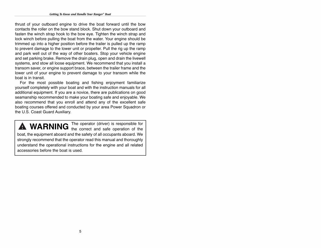
The operator (driver) is responsible forthe correct and safe operation of the
boat, the equipment aboard and the safety of all occupants aboard. Westrongly recommend that the operator read this manual and thoroughlyunderstand the operational instructions for the engine and all relatedaccessories before the boat is used.
WARNING

Be Responsible For Safer Boating
BE RESPONSIBLE FOR SAFER BOATING
• ALCOHOL and DRUGS - The debilitating effects of alcohol and otherdrugs reduces reaction time and detracts from judgment. Thecombined effect of the outdoor environment… sun, heat, wind, roughwater, and noise can be more fatiguing than one would imagine and,combined with drugs or alcohol, can be very dangerous.
• GAME PLAN - Tell a friend, neighbor or another family member whereyou will be boating and when you plan to return. Be certain that thisindividual has a good description of your boat and any other identifyinginformation that could be needed to help find you should an emergencyarise.
• TOOLS and SPARE PARTS - Many people have been stranded byminor breakdowns that they could have repaired themselves. It is agood idea to carry a few tools and common spare parts and to befamiliar with simple repairs that you can easily accomplish.
• GASOLINE RESERVES - Never push your boating range to the limitof your gas tank capacity… one-third of the fuel to go, one-third tocome back and one-third to reserve.
• GOOD BOAT KEEPING - A clean boat is a safer boat. Take care to seethat rods, lures, nets, gaffs and other potentially harmful gear areproperly stowed so that it cannot blow or move around while the boat isunderway. Perform all maintenance and safety checks regularly. Secureall icebox or cooler lids and place any trash or debris safely under coveruntil the trip is over.
• SPEED and SKILL - The fast and powerful boat can require theoperator to exercise a high level of skill and attention to driving. Only goas fast as your skill and good judgment dictates is safe. You are incharge of the well being of your passengers and yourself. Be alert forany hazards in the water and operate your boat only in such a manneras would be appropriate for the water conditions. Be a good boating“neighbor” and do not create a hazard or annoyance to others. The bestsafety equipment is your own good judgment.
• SKIERS and SWIMMERS - Do not allow operation of the engine whenanyone is in the water near the stern of the boat. Never back up to adown skier or anyone in the water. Never drive your boat directly behinda skier.
6

Carbon Monoxide Warning
CARBON MONOXIDE
Carbon monoxide is a deadly gas that is odorless, tasteless andcolorless. It is present in the exhaust of internal combustion engines.Inhaling sufficient concentrations of carbon monoxide can be fatal withinminutes. Early signs of carbon monoxide poisoning may includeheadache, nausea, fatigue, drowsiness, confusion and vomiting. DONOT MISTAKE THESE SYMPTOMS FOR SEASICKNESS. If any ofthese symptoms occur to you or any of your passengers, ventilate theboat by opening the side curtains or forward hatch to remove the fumesand immediately seek medical attention.
Carbon monoxide can be drawn into the cockpit area over the stern ofthe boat. When operating the engine, ventilate the cockpit area byremoving side curtains or opening forward hatches to allow fresh air toflow though. Do not operate the engine if your boat is moored in aconfined area.
7
Exhaust from a running engine cancause an accumulation of carbon
monoxide gas in the cockpit area when the canvas top and sidecurtains are installed. Provide adequate ventilation when thesecoverings are installed in their closed positions.
WARNING

8
Getting to Know and Handle Your Ranger Boat ......................................2Be Responsible for Safer Boating ............................................................6Carbon Monoxide Warning ......................................................................7Special Information ..................................................................................9
Your Ranger Dealer’s Responsibilities ................................................9Owner/Operator’s Responsibilities ....................................................10Warning and Cautions ........................................................................11Hazard Labeling ........................................................................12 & 13
Hull Identification Plate ..........................................................................14U.S. Coast Guard Capacity Information Plate ........................................15Recommended On-Plane Seating Locations..........................................16Important Health and Safety Information................................................17Fuel System ............................................................................................17Your Livewell Aeration System................................................................19Steering at Console ................................................................................25Your Boat’s Finish ..................................................................................30
Maintenance and Repair ....................................................................30Your Power Pedestals ............................................................................33Key Locks, Carpet, and Upholstery ........................................................35Cleaning Marine Vinyl .................................................................. 36 & 37Adding Accessories To Your Boat ..........................................................38Hook Up of Trolling Motor Leads ............................................................39Wiring Diagrams ....................................................................................40Electrical System ....................................................................................50
Fuse Panel Information ......................................................................50Fisherman Series................................................................................51Saltwater Series ................................................................................54Z Comanche ......................................................................................55Installation of Trolling Motor Plug ......................................................59Installation of Battery Charger Plug....................................................60
Federal Requirements for Recreational Boats........................................62Boat Data (Owner’s Information) ............................................................64
Y O U R R A N G E R T R A I L ® T R A I L E R
General Information and Maintenance ..................................................65Contained Oil Orbital Lubrication (COOL) Hubs ....................................66Trailer Brakes..........................................................................................67RangerTrail Wiring ..................................................................................68Swing Hitch ............................................................................................70Before Towing Your Ranger Trail Trailer ................................................70Towing Your Ranger Trail Trailer ............................................................70Trailer Exploded View ....................................................................72 & 73Ranger Trail Parts List ............................................................................74Limited Warranty ............................................................................75 & 76
T A B L E O F C O N T E N T S
Special Information
SPECIAL INFORMATION
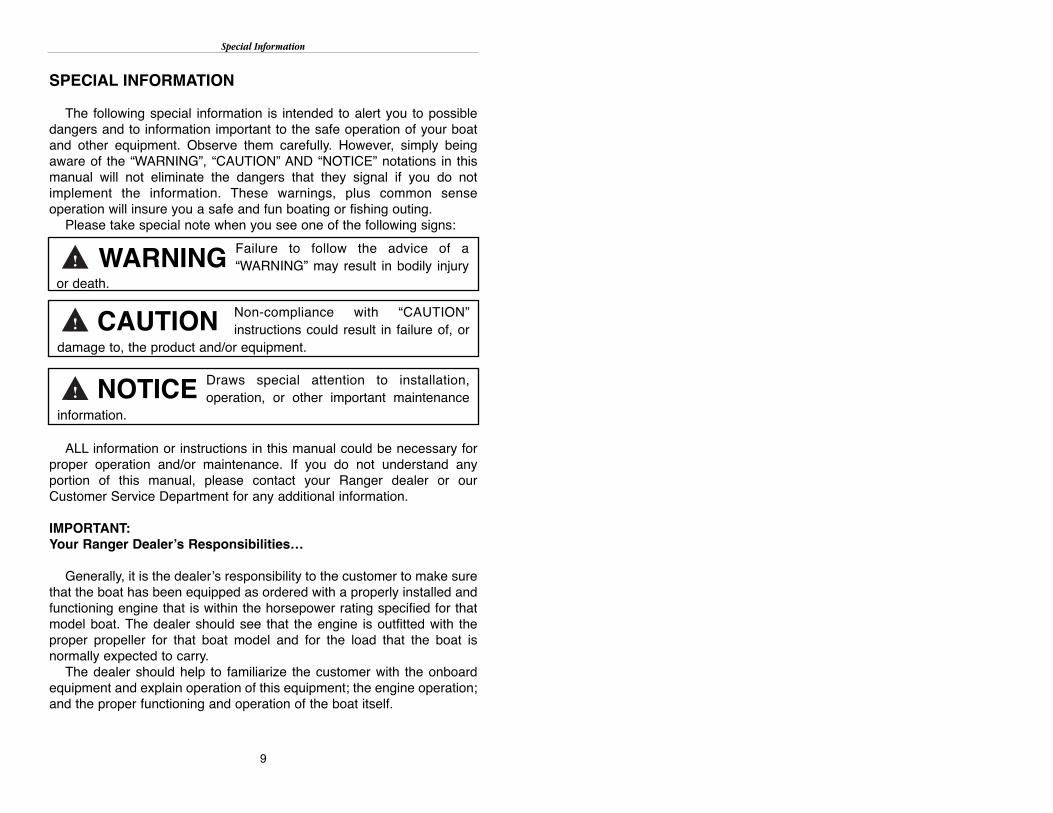
The following special information is intended to alert you to possibledangers and to information important to the safe operation of your boatand other equipment. Observe them carefully. However, simply beingaware of the “WARNING”, “CAUTION” AND “NOTICE” notations in thismanual will not eliminate the dangers that they signal if you do notimplement the information. These warnings, plus common senseoperation will insure you a safe and fun boating or fishing outing.
Please take special note when you see one of the following signs:
ALL information or instructions in this manual could be necessary forproper operation and/or maintenance. If you do not understand anyportion of this manual, please contact your Ranger dealer or ourCustomer Service Department for any additional information.
IMPORTANT:Your Ranger Dealer’s Responsibilities…
Generally, it is the dealer’s responsibility to the customer to make surethat the boat has been equipped as ordered with a properly installed andfunctioning engine that is within the horsepower rating specified for thatmodel boat. The dealer should see that the engine is outfitted with theproper propeller for that boat model and for the load that the boat isnormally expected to carry.
The dealer should help to familiarize the customer with the onboardequipment and explain operation of this equipment; the engine operation;and the proper functioning and operation of the boat itself.
9
Failure to follow the advice of a“WARNING” may result in bodily injury
or death.
Non-compliance with “CAUTION”instructions could result in failure of, or
damage to, the product and/or equipment.
WARNING
CAUTION
Draws special attention to installation,operation, or other important maintenance
information.
NOTICE

Special Information
Prior to delivery, the dealer should make certain that the product andequipment is completely operational; the proper propeller is installed; andthat all oil, fuel system and lubrication systems are understood. Thedealer should explain the operation of all instrumentation equipment, andthe boat electrical and livewell systems.
The dealer should check for correct carburetor adjustment, throttle andsteering functioning, and instrumentation accuracy. Engine cooling watershould be properly circulating.
The dealer should test for maximum engine RPM as specified in theengine manufacturer’s specification sheet(s) and/or engine owner’smanual for proper operation of all equipment and for proper adjustmentof steering effort and direction. All necessary adjustments for maximumefficiency should be made.
Owner/Operator’s Responsibilities…
It is the owner/operator’s responsibility to perform all safety checks andto ensure that all lubrication and maintenance instructions are compliedwith for maximum safety and proper operation.
It is also the owner/operator’s responsibility to return the unit to theRanger dealer for a periodic checkup.
The owner/operator is responsible for the correct operation of the boatand for the safety of its occupants. Be sure that all operators read thismanual before attempting to operate the boat. Your passengers shouldbe shown the location and use of all emergency equipment and onepassenger should be instructed how to handle the boat in case ofemergency. U.S. Coast Guard requirements for PFDs (Personal FlotationDevices, or Life vests) can vary, depending on the type of boat. Be sureto comply with the U.S. Coast Guard regulations that apply to your boat.The owner/operator should, however, make certain that all passengers inthe boat are in possession of, and are securely wearing a PFD wheneverthe boat is in operation. We strongly recommend that an engineemergency stop switch be securely connected to the boat operator anytime that the engine is in operation!
Learn the waterway rules of the locality in which you intend to operateyour boat. Navigable waterways are controlled by Federal regulationswhile inland lakes and Canadian waters are controlled by localjurisdictions. Obey all regulations to protect yourself, your passengers,and fellow boating enthusiasts.
10
Special Information
Before boating, obtain the weather forecast for your area. Familiarizeyourself with the weather bureau warning system signal(s) and waterwaytraffic sign/marking information.
Contact your local U.S. Coast Guard Auxiliary and take advantage oftheir excellent boating and safety classes and seasonal boat inspections.
11
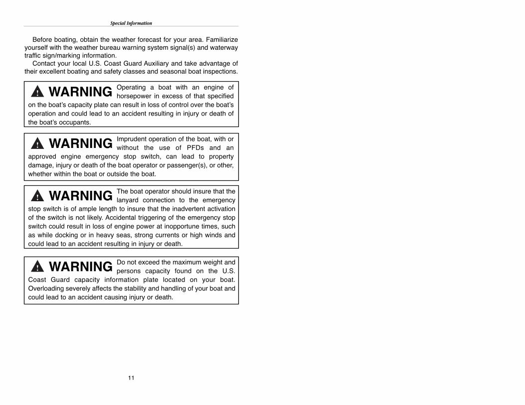
Operating a boat with an engine ofhorsepower in excess of that specified
on the boat’s capacity plate can result in loss of control over the boat’soperation and could lead to an accident resulting in injury or death ofthe boat’s occupants.
Imprudent operation of the boat, with orwithout the use of PFDs and an
approved engine emergency stop switch, can lead to propertydamage, injury or death of the boat operator or passenger(s), or other,whether within the boat or outside the boat.
WARNING
WARNING
The boat operator should insure that thelanyard connection to the emergency
stop switch is of ample length to insure that the inadvertent activationof the switch is not likely. Accidental triggering of the emergency stopswitch could result in loss of engine power at inopportune times, suchas while docking or in heavy seas, strong currents or high winds andcould lead to an accident resulting in injury or death.
WARNING
Do not exceed the maximum weight andpersons capacity found on the U.S.
Coast Guard capacity information plate located on your boat.Overloading severely affects the stability and handling of your boat andcould lead to an accident causing injury or death.
WARNING

Hazard Labeling
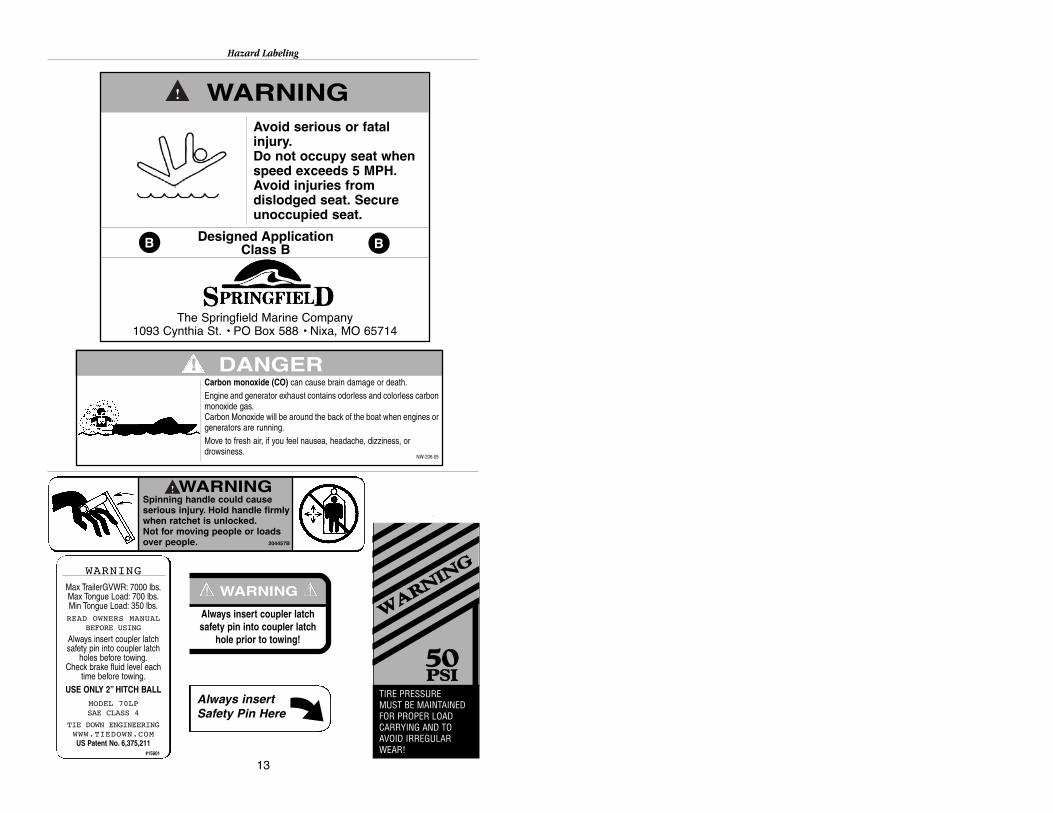
HAZARD LABELING
The hazard warning decals shown on the following pages may befound in various locations on your boat and trailer (photos are notnecessarily to scale). Some labels are not appropriate for everyboat/trailer model so your rig may not have them all. Check with yourRanger dealer to find out what labels your boat and trailer should haveand ask them to order any necessary replacements.
12
Install ski pylon securely before use.Insert pin thru receiver and ski tow pylon.Pushing pylon into mounting hole until redline is no longer visible. Install pin thrureceiver and pylon to secure position.Failure to secure pylon may result inpossible injury or death.
WARNINGRotating propeller can causeserious injury or death.Never approach or use ladderwhen motor is running.
WARNINGRotating propeller can causeserious injury or death.Shut off motor when nearpersons in water.
WARNINGFuel vapors are a fire and explosionhazard. To avoid injury or death, do notstore fuel or flammable liquids here.
WARNINGAvoid serious injury or deathfrom fire or explosion, resultingfrom leaking fuel. Inspectsystem for leaks at least oncea year.
WARNINGAvoid serious injury or death fromfire, explosion or electrical shock.
• Ensure power is turned off beforeconnecting to an AC source.
• Make connection in an openatmosphere free of explosive fumes.
• Make connection in a secure mannerthat will avoid contact with the water.
WARNING
WARNINGSUDDEN TURNS ABOVE 30 MPH MAY CAUSELOSS OF BOAT CONTROL. AVOID SERIOUS
INJURY OR DEATH. REDUCE SPEED BEFOREATTEMPTING A SUDDEN SHARP TURN.
READ OWNERS MANUAL.
!
WARNINGCarbon monoxide (CO) can causebrain damage or death.Engine and generator exhaust contains odorless and colorless carbonmonoxide gas.Signs of carbon monoxide poisoning include nausea, headache, dizziness, drowsiness, and lack of consciousness.Get fresh air if anyone shows signs of carbon monoxide poisoning.See Owner’s Manual for information regarding carbon monoxide poisoning.
NW-204-05
WARNINGMMAAXXIIMMUUMM HHOORRSSEEPPOOWWEERR RRAATTIINNGGSS
112255 HHPP WWIITTHH TTIILLLLEERR SSTTEEEERRIINNGG115500 HHPP WWHHEENN EEQQUUIIPPPPEEDD WWIITTHH
EENNGGIINNEESSTTEEEERR®® HHYYDDRRAAUULLIICCTTIILLLLEERR SSTTEEEERRIINNGG SSYYSSTTEEMM
!
Hazard Labeling
13
WARNINGAvoid serious or fatalinjury.Do not occupy seat whenspeed exceeds 5 MPH.Avoid injuries fromdislodged seat. Secureunoccupied seat.
Designed ApplicationClass BB B
The Springfield Marine Company1093 Cynthia St. • PO Box 588 • Nixa, MO 65714
WWAARRNNIINN
GG
5500PPSSII
TIRE PRESSUREMUST BE MAINTAINEDFOR PROPER LOADCARRYING AND TOAVOID IRREGULARWEAR!
Always insertSafety Pin Here
Always insert coupler latchsafety pin into coupler latch
hole prior to towing!
WARNING! !
DANGERCarbon monoxide (CO) can cause brain damage or death.Engine and generator exhaust contains odorless and colorless carbonmonoxide gas.Carbon Monoxide will be around the back of the boat when engines or generators are running.Move to fresh air, if you feel nausea, headache, dizziness, or drowsiness.
NW-206-05
!!
WARNINGSpinning handle could causeserious injury. Hold handle firmlywhen ratchet is unlocked.Not for moving people or loadsover people. 204457B
WARNING
Max TrailerGVWR: 7000 lbs.Max Tongue Load: 700 lbs.Min Tongue Load: 350 lbs.READ OWNERS MANUAL
BEFORE USING
Always insert coupler latchsafety pin into coupler latch
holes before towing.Check brake fluid level each
time before towing.USE ONLY 2” HITCH BALL
MODEL 70LPSAE CLASS 4
TIE DOWN ENGINEERINGWWW.TIEDOWN.COMUS Patent No. 6,375,211
#15601

Hull Identification Plate
HULL IDENTIFICATION PLATE
The hull I.D. Plate is located on the outboard side of the starboardtransom, above the water line, and contains the following information:
(1) Boat patent information
(2) Model Number - This number should be referred to when ordering parts or making other inquiries.
(3) Hull Identification Number (Serial Number) - Should also beincluded in any inquiries or when ordering parts. The U.S.C.G.requires the H.I.N. number be permanently affixed and remain onthe starboard transom of the boat. Do not alter this plate in any way.
14
Model Number
Year Mfg. Year Model

U.S. Coast Guard Capacity Information Plate
U.S. COAST GUARD CAPACITY INFORMATION PLATE
Familiarize yourself with your boat’s maximum capacities. Do notexceed the maximum weight (in pounds) or persons capacity (number)found on the U.S.C.G. capacity information plate attached to your boat.Know the ratings and load your boat accordingly. It is a must forsafe boating.
15
Failure to observe maximum weight andhorsepower capacities could create
conditions favorable to an accident that could result in injury or death tothe occupants.
WARNING

Recommended On-Plane Seating Locations
RECOMMENDED ON-PLANE SEATING LOCATIONS
A decal similar to the one in Fig. 1, below, should be found on your boatin the area of the U.S. Coast Guard Capacity plate. The areas marked by“X’s” are the areas of the boat considered safe and suitable for on-planeseating. The operator of the boat should be familiar with these locations.The boat should not be operated at or above planing speeds with personson board not seated in the designated areas shown.
FIG. 1
16
Do not operate the boat on plane withpersons located outside the on-plane
locations shown on the decal. Failure to do so could cause a person(s)to be thrown overboard resulting in injury or death.
WARNING

IMPORTANT HEALTH AND SAFETY INFORMATIONABOUT YOUR NEW BOAT
FUEL SYSTEMThe fuel system consists of a fuel tank equipped with an electric
sending unit. The fuel level is displayed on the console mounted gaugewhen the ignition switch is “on”. On models with two tanks, a consolemounted switch marked with a fuel pump symbol or just “fuel”, is used toswitch the gauge from one tank to the other. Push the fuel pump symbolswitch to display the level in tank 1 (starboard) or tank 2 (port). Or, onsome models, push the switch to the left to display the port tank fuel leveland push to the right to display the starboard tank fuel level. The centerposition is “off”. A fuel hose connects the fuel tank to the engine. Onmodels with more than one tank, a switch valve is installed to switch fromtank to tank. This valve, located at the driver seat, on the panel supportingthe driver and passenger seat or near the splashwell, depending on themodel, is clearly marked and easily operated. Some models have amanual fuel shutoff valve located in the pick up tube at the fuel tank.
Fuel System
17
A wide variety of components used onthis vessel contain or emit chemicalsknown to the State of California to cause
cancer and birth defects and other reproductive harm.EXAMPLES INCLUDE:• Engine and generator exhaust• Engine and generator fuel, and other liquids such as coolants and oil,
especially used motor oil.• Cooking fuels• Cleaners, paints, and substances used for vessel repair• Waste materials that result from wear of vessel components• Lead from battery terminals and from other sources such as ballast or
fishing sinkers.TO AVOID HARM:• Keep away from engine, generator, and cooking fuel exhaust fumes• Wash areas thoroughly with soap and water after handling
the substances above.
Spilled fuel is a fire hazard. DO NOToverfill or overflow the tank, or allow fuel
spills into the hull or bilge. To help prevent fuel blow back, always filltank slowly and monitor fuel flow as filling. If spillage should occur,clean up immediately and dispose of soiled rags/towels in a propercontainer.
WARNING
WARNING

Contact your Ranger dealer for information on proper fuel shutoff valveaccess.SAFETY AND MAINTENANCE TIPS
The fuel system in your Ranger requires little or no maintenance.However, the periodic inspection outlined below is stronglyrecommended. Contact your Ranger dealer for proper fuel tank accessfor your model.(1) Check fuel tank(s) for leakage, especially around electric sender and
fuel hose connections.(2) Check fuel tank hold down brackets, making sure they are secure.(3) Check battery hold down or boxes, making sure they are secure.(4) Do not store items on, in, or around fuel tanks or batteries. “Good
housekeeping” in this compartment is essential to safe boating and amaintenance-free fuel and electrical system.
(5) Check hose connections at the deck fuel fill, fuel tank vent, and (ifequipped with more than one tank), the fuel switch valve.
Naturally, a leak-free fuel system is a MUST for proper engine operationand on-board safety. Always inspect for fuel leaks prior to connectingbattery charger to your engine cranking battery. Rear batterycompartment lid should always be open for ventilation when charging thebatteries.
18
Avoid serious injury or death from fire orexplosion resulting from leaking fuel.
Inspect system for leaks at least once a year.
WARNING
Maintenance or repairs should beperformed by your Ranger dealer or other
qualified personnel.
CAUTION
Fuel vapors are a fire and explosionhazard. Do not store fuel or flammable
liquids in boat. Ventilation has not been provided.
WARNING
Fuel System

Your Livewell Aeration System
YOUR LIVEWELL AERATION SYSTEM
The livewell aerator system in a Ranger boat is designed to supply thewater and oxygen necessary to the survival of your catch. This patentedsystem not only allows fresh water to be pumped in through the aeratorsupply line(s), but also permits recirculation and aeration at any speed ofboat operation.
The recirc position (with aerator running) will only recirculate whatwater is in the well. It does not bring in any fresh water. This positionprovides a more positive seal and is good to use if you are going totransport live fish in the well.
The auto position also holds the water in the well and in conjunctionwith the aerator will allow a mix of fresh water intake and recirculateexisting water. This would be the normal position for a day of fishing. Theempty position is just that, to empty the water from the well.
On models without digital switching, the livewell aerator timer locatedon the driver’s console, controls the off time of the aerators when thepump switch is in the automatic position. The timer starts and stops thepump at intervals determined by the setting on the timer. Full counter-clockwise is minimum off time and full clockwise is maximum off time. Tohave the aerator pumps run continuously, set the pump switch to themanual position.
19
EMPTY
AUTORECIRC

Your Livewell Aeration System
LIVEWELL PUMP-OUT
Your new Ranger may be equipped with a livewell pump-out system.To use this pump out feature, put the livewell control valve in the recircposition and pull out on the aerator spray head. Turn on the aerator andthe water in the well will be emptied. To fill the livewell and resume normaloperation, push the aerator spray head in and set the livewell valve to theauto position.
20
Pump-Out Valve Operation
To pump-out, pull the Power-Nozzle aerator head toposition shown. NOTE: Be sure you are operating inrecirculation mode.

Your Livewell Aeration System
LIVEWELL PLUMBING ASSEMBLY
ITEM NUMBER PART NUMBER DESCRIPTION
AA 7415915 3/4” x GHT Swivel Female Insert
X 7100111 90 Deg. Black thru Hull 3/4”
W 7843112 5/8” - 1-1/2” Hose Clamp HF 16SS
V 7843092 Clamp, 1/2-1” Hose, HF 10SS
U 7400262 3/4” blk Spiral Reinf Wtr Hose
T 7400225 1-1/8” ID Blk Bilge Hose
O, P, R, S 7400262 3/4” Blk Spiral Reinf Water Hose
N PVC ASSEMBLY
M1 7100162 1-1/8” Closed Cell Neop. Gasket
M 7100125 Black 90 Deg 1-1/8” Elbow W/Nut
K 7100110 1-1/8” Black Thru Hull Grommet
J 7100118 Transom Mt L/W Screen (2 pc-sml)
H 7100112 Black 3/4” Thru Hull Straight
5900006 Actuator (Center Empty) Livewell
E 5903070 Actuator Valve “Center Empty”
D 6000057 Pump, Aerator,750GPH W/90DG ELB
CC 7415855 Venturi Air Aeration Sys Kit
C 6000050 Pump-Out/Aerator Combo
B 7415816 3/4 Male NPT x Male GHT Elbow
A 7100130 Filter, L/W, Int, Mesh
21

Your Livewell Aeration System
22
SALTWATER LIVEWELL PLUMBING SYSTEMMODELS 168, 169, 191, 223, 2000, 2180, 2200, 2300, 2400
PUMP
FILTER
VALVE
Aer. Headw/valve
DirectionalAer. Head
1 1/2” Standpipe
1 1/8” Plug Drain
Operation Instructions:Your livewell Aeration System1: Valve (shown in closed position) should be left open2: Close valve when cleaning filter or servicing pump.
3: The livewell (all except optional leaning post/bait well) aerator head isadjustable with a valve. The head also is threaded for a hose connection.Recirculate pump does not have valve.
4: Install drain plug (1-1/8”) or overflow pipe (1-1/2” ) in livewell to hold water.Pull to drain.

Your Livewell Aeration System
RECIRCULATION PUMP STANDARD ON STERN LIVEWELL,OPTIONAL LEANING POST/BAIT WELL
MODELS 191, 223, 2000, 2180, 2200, 2300, 2400
23
Fish box drain valve on models 2180, 2300. Located in battery compartment
Your Livewell Aeration System
MAINTENANCE TIPS FOR AERATOR SYSTEM(1) Remove screens only for flushing aerator system.(2) Keep screens in place for cleaning and during operation. Replace
damaged or broken screens immediately.(3) Do not exceed the recommended fuse size on the aerator pumps (a
larger fuse WILL NOT make a stronger aerator system!).(4) Lubricate pivot on livewell control cable periodically using light weight
machine oil.(5) Continual operation of pump (especially dry) will damage pump. Be
sure aerator switches are “off” when storing, etc.
TROUBLESHOOTING
�� Pump runs, but will not pump water:Í Entrapped air pocket around pump impeller has “air locked”
pump. With valve in “fill” position, back boat up slowly to expelentrapped water.
Í On Saltwater models, be sure high speed pickup valve is open(handle in line with valve) and drive boat forward to expelentrapped air.
Í Grass, sticks, or other debris have clogged the filters or cavityaround the pump impeller, restricting water flow to pump. Cleanscreens, or remove screens and flush system with garden hoseusing moderate pressure.
Í On Saltwater models, close the valve, unscrew filter, clean filterelement and reinstall. Open valve.
�� Pump will not run (no “hum” is heard):Í Make sure switch is in the “Manual” position (in “Automatic” the
pump could be working, but in off time).Í Check master breaker switch in the rear compartment.Í Check fuse, breaker or flashing LED light on digital switching
models. Replace or reset as necessary.Í Check wire connector at pump.Í Replace pump.
�� Livewells will not hold water in “Fill” position.Í Flush system to clear debris from livewell valve.Í Check cable to valve connection for proper adjustment.Í Remove cable, put water in livewell to see if well will hold water
with cable removed. If so, adjust cable to match actuator arm.Í Remove valve and disassemble. Clean inside of valve with warm
soapy water and inspect flappers for nicks, cuts and abrasions.Replace flappers if necessary.
On Saltwater models, be sure drain plug or stand pipe is installed.
24

STEERING AT CONSOLE
Your new Ranger may be equipped with Teleflex hydraulic steering.This system is designed to help reduce engine torque felt at the wheel
(see Fig. 3), while providing excellent steering response. However, this isnot to be interpreted in any way as an “Automatic Pilot”. A firm grip on thewheel is required at all times. Read the steering owner/installation manualfor maintenance instructions.
Other Ranger models may be equipped with no feed back steering.This is mechanical steering that is designed to help reduce engine torque,felt at the wheel, to a minimum. However, a firm grip on the steering wheelis required at all times.
You should familiarize yourself with the feel of the steering at variousspeeds and trim settings. NEVER exceed speeds beyond your comfortlevel.
Steering
25
The steering in your boat is one of themost important items and should be
checked by the driver every time the boat is used. You should schoolyourself and make it a habit to check the steering methodically. Looseor worn steering could lead to an accident causing injury or death.
WARNING
Due to the special valving in the hydraulichelm the steering wheel may not be in the
same position each time the steering is returned to center. This isnormal operation and should be no cause for alarm.
NOTICE
The driver must always keep a firm gripon the steering wheel. Failure to do so
could lead to an accident causing injury or death.
WARNING

Steering
TELEFLEX HYDRAULIC STEERINGRemove, clean and grease the support tube annually with qualitymarine grease.
Check the steering fluid level in the helm. It should be maintained at noless than 1/2” and no more then 1/8” below the bottom of the filler capthreads. Be careful not to overfill.
Replace any hoses showing signs of wear and remove the cause or re-route hoses.
Check fittings and seal locations for leaks/damage and service asnecessary.
If you have installed a jack plate, make sure that there isn’t anyinterference between the jack plate and your steering cylinder. If there isinterference, it may occur during full tilt. Lift restrictors or a Tilt StopSwitch should be installed. Please consult your engine manufacturer.
26
Failure to comply with maintenancechecks may result in loss of steering,
causing property damage and/or personal injury. Maintenancerequirements will vary depending on usage and climate. Bi-annualinspection by a qualified marine mechanic is required.
WARNING
Grease rod, tilt tube and support bracketholes once a year.CAUTION

Steering
For complete installation and troubleshooting information, pleaserefer to your SeaStar installation instructions, Book 1.1 (Part #296784).
SEAL REPLACEMENT KIT (PART # HS5157) FOR: FRONT MOUNT CYLINDER (PART # HC5345)
Item Part # Quantity Description1 797021 2 Seal Gland Only2 745920 1 Seal Gland Assembly Guide Tool3 745525 1 Pin Wrench Only4 828980 1 Bleeder Fitting5 600601 1 Elbow Fitting
SEAL KIT # HS5157
1 797021 2 Seal Gland Only2 745920 1 Seal Gland Assembly Guide Tool3 745525 1 Pin Wrench Only
27

Steering
STEERING CONNECTIONS AT ENGINE
The steering may be connected at the engine by a method similar to theones shown in Figures 4 & 5 ( page 29).
Because Ranger does not supply the “cable to engine” connectors,except on pre-rigged packages, we will not make specific installation ortorque recommendations. However, Figures 4 & 5 show maintenance andcheck points that should be regularly inspected.
28
See your authorized marine dealer forspecific information concerning
maintenance of engine connections.
CAUTION

Steering
29
See engine owner’s manual for propergreasing and maintenance of engine
link rod and steering kit.
CAUTION
Your Boat’s Finish
YOUR BOAT’S FINISH…MAINTENANCE AND REPAIR
The gel-coat (color) used on your Ranger® Boat is of the highestquality available today. To keep it looking new and in good conditionthese tips will prove helpful.
�� A light duty rubbing compound (available at most auto parts stores)is recommended for stains such as mold, water lines on the hull, finescratches on finish or just to bring back that “look new” shine.
�� Automotive wax or polish is good for preserving the shine andbuilding an “armor coat” to prevent scratches and will also helpprotect hull while in wet storage.
�� A boat cover (which is available from your Ranger dealer) is also awise investment to help prevent damage while the boat is at home oron the road.
Careful as you may be, you will get that scratch from the dock orbeach that will need some attention. Most Ranger dealers are equippedto do fiberglass repair, and large jobs are better left to the experts.However, minor scratches, chips, and gouges may be repaired byyou.These instructions are to repair solid color gel-coat only, notpoliflake:
1. Using masking tape, tape around damaged area slightly larger thanactual flaw, keeping area to be repaired as small as possible.
2. Remove any damaged glass or gel-coat. Sand damaged area andall surface inside tape, enough to rough up area and remove shine,using #220 grit dry sand paper.
30
Do not use acids or other strong chemicalsto clean your boat.NOTICE

Your Boat’s Finish
3. Wash area with a solvent such as acetone and allow to dry.
4. Using Ranger touch-up gel-coat or putty only, thoroughly mix 1%catalyst (MEKP) with desired amount of gel-coat or putty.
5. With a putty knife, trowel catalyzed gel-coat in desired area, leaving itslightly higher than the original surface to allow for shrinkage.
6. When patch has dried, remove masking tape and carefully sand backto the original shape using #600 grit WET sandpaper. Then buff witha light duty buffing compound.
NOTE: Area may have to be filled more than once due to shrinkage.
NOTE: Due to different dye lots the color may vary somewhat. However,we take all the steps to keep our color consistent.
31
Gel-coat will not cure by itself. You must usea catalyst.NOTICE
Do not hold buffer in one area long enoughto burn gel-coat.NOTICE
These materials are very flammable. Donot smoke or use electric equipment
while using them. Improper handling could result in an explosionresulting in injury or death.
WARNING
Your Boat’s Finish
32
Gel-coat will not cure by itself. You must usea catalyst.NOTICE
Do not sand metalflake surfaces. A differentprocedure is used to repair these finishes.
You should contact your Ranger dealer for more information.
NOTICE

Your Power Pedestals
YOUR POWER PEDESTALS
A “power pedestal” is a nitrogen gas filled steel cylinder that is usedto raise and lower the fishing seats mounted on the forward and aftcasting platforms. This enables you to select the proper seat height forcomfort in any fishing situation. Pushing the empty seats all the waydown helps to provide an unobstructed viewing area around the boatwhen underway.
To raise the seat, simply lift your weight slightly off the seat whileraising the seat actuating lever simultaneously. To lower the seat, keepyour weight on the seat and lift the lever up.
These pedestals are constructed to the highest standard ofworkmanship and will give years of trouble-free service. A minimumamount of care will insure proper operation. Periodically apply a lightweight oil (like household “3 -in-1” oil) to the power unit piston. Takecare not to over stress the pedestal by placing excessive strain on theseat and power unit while it is extended into the full up position. Alwayslower the seat to the full down position when the boat is underway. Werecommend that the seat and pedestal be removed from the frontcasting deck and remounted into the special base mounted in the frontof the deck floor when running. Should your boat not have the additionalbase, the front fishing seat should be removed and securely placed inthe floor of the boat.
Your power pedestals are warranted for three years against defectsin materials and workmanship. Should a pedestal fail, return the unit toSpringfield Marine, Attention: Warranty/Repair, Hwy. 160, P.O. Box 588,Nixa, Missouri 65714, or call 417-725-2667. Repairs not covered bywarranty will be charged at their regular rate.
If your power pedestal will not remain in position, either up or down,you may need to make a minor adjustment to the air cylinder thatcauses the pedestal to be raised up and down.
With your chair removed from the pedestal, use a Phillips #0screwdriver to move the adjustment screw as shown in theaccompanying diagram.
33
Power unit is under pressure. Do notattempt to disassemble it or tamper with
it in any way. Improper handling could result in severe injury or death.
WARNING

Your Power Pedestals
If your seat will not raise up to the proper height, adjust the screwapproximately 1/4 (one-quarter) turn in a counter-clockwise direction andtry the pedestal again.
If your seat will not remain in the upright position, move the adjustmentscrew approximately 1/4 (one-quarter) turn in a clockwise direction.
NOTE: You may need to fine-tune your pedestal by moving theadjustment screw a bit more in one direction or the other.
34
Key Locks, Carpet and Upholstery
KEY LOCKS, CARPET AND UPHOLSTERY
Your Ranger® boat has been equipped with top-quality marine gradekey locks to secure your storage areas. Should your boat be subjected touse in or near salt water, care should be taken to flush the locks outthoroughly with fresh water to prevent corrosion.
The carpet in your boat is the finest grade available. Although thespecial backing is RESISTANT to oil and gasoline, spills should beremoved with soap and water to maintain the good looks and extend thecarpet life. A car-wash is suitable for washing and rinsing your carpet aswell as cleaning the fiberglass surfaces.
Your Ranger upholstery is top-grade marine vinyl. Naturally, thesuppleness and color fidelity of the upholstery is best maintained bystoring your boat out of direct sunlight. Cleaning and conditioning of yourupholstery is best accomplished with an approved, top-quality vinylcleaner. To loosen stubborn soil or embedded dirt in textured surfaces,use a soft bristle brush, your approved cleanser, followed by wiping witha damp sponge. See specific suggestions for cleaning of marine vinyl onpages 36 and 37.
35
The popular and effective “fish scents” thatare commonly sprayed on lures today will
cause deterioration of the carpet backing. Use caution to spray theseformulas well away from your boat carpet! Any spills should be cleanedup promptly.
NOTICE
Do not use acetone, paint remover orother strong solvents on boat’s
upholstery.
CAUTION

Key Locks, Carpet, and Upholstery
CLEANING MARINE VINYL
For general purpose cleaning, use Vinyl Finish Vinyl Cleaner,Fantastik, or warm water with a mild dish soap such as Dawn or Ivory.Gently scrub with a small soft bristle brush.
For dirt build-up, use Vinyl Finish Vinyl Cleaners. Let soak forapproximately 10 minutes, then gently scrub with a soft bristle brush. Forspecific stain removal, refer to the chart on page 36 or the stainingagent’s stain removal instructions.
USE DO NOT USEVinyl Finish Vinyl Cleaner Formula 409Dish Soap (Dawn, Ivory) Murphy’s Oil SoapFantastik Simple Green303 Protectant DC Plus
ArmorAllTop Kote SealantSon-of-a-GunOrange 88 DegreaserRoll-OffBleach/Baking SodaTurtle Wax Tar RemoverAPCOHarbor Mate
Certain household cleaners, powdered abrasives, steel wool, andindustrial cleansers can cause damage and discoloration and are notrecommended.
Dry cleaning fluids and lacquer solvents/acetone (for example, nailpolish remover) should not be used as they will remove printed patternand/or gloss.
Waxes should be used with caution as many contain dyes or solventsthat can permanently damage the protective coating.
36
DO NOT use Formula 409 (the bottlestates the product should not be used on
vinyl.)DO NOT use kerosene, gasoline, or acetone, as they will remove theprotective marine top coat on your vinyl.DO NOT use any silicone based protectants. They will extract theplasticizers, leaving the vinyl hard and brittle, and eventually crackingwill occur.
CAUTION

Key Locks, Carpet, and Upholstery
This chart contains methods for removing common stains and soils:
A. Medium-soft brush, warm soapy water. Rinse. Dry.B. Vinyl Finish Cleaner or household cleaner such as Fantastik.C. One tablespoon ammonia, one-fourth cup hydrogen peroxide, three-
fourths cup water applied with medium soft brush. Rinse. Dry.D. Wipe or scrape off excess (chill gum with ice first).E. Denatured Alcohol. Rinse. Dry.F. Follow instructions of stain agent manufacturer.
STEP 1 STEP 2 STEP 3
Ballpoint Ink* E B A
Chewing Gum D B A
Coffee, Tea, Chocolate B
Crayon D B
Grease D B F
Household Soil A B
Ketchup A B
Make Up (Lipstick, eye shadow etc.) A B
Mildew, Wet Leaves* C B A
Motor Oil B
Paint, Dried Oil Base D B A
Paint, Fresh Oil Base D A F
Paint, Latex A B F
Permanent Marker* E B C
Shoe Polish* D B F
Spray Paint B F
Suntan Lotion* A B
Tar/Asphalt D B
Yellow Mustard A B C
* Suntan lotion, tree pollen, wet leaves, and some other products containdyes that stain permanently.
37
Adding Accessories To Your Boat
ADDING ACCESSORIES TO YOUR BOAT…
The bow section of the gunwale is properly reinforced for installingsuch accessories as trolling motors and depth sounders. We recommendthrough-bolting all trolling motors, anchor davits and other heavieraccessories. Normally 1/4” stainless steel bolts with self locking nuts and1-1/4” fender will do the job. Lightweight depth sounders or similarequipment and hardware can be installed using #8 or #10 stainless steelscrews. Always drill a pilot hole through the fiberglass (just smaller thanthe screw you’re going to use) and use a counter sink to chamfer the pilothole before attempting to install a screw. This lessens the chance of“stripping” the hold or chipping the gel-coat around the hole.
If additional instruments are desired on the console, holes may bedrilled using a hole saw of the proper size.
When installing additional electric accessories, always use the propergauge (size) wire recommended for that item. Insure that the proper sizebreaker or fuse is used. “Splicing” into another accessory’s power supplycould overload the circuit and should be avoided.
38
Use Marine Sealer around all screwsinstalled into transom or floor of boat. When
installing screws below water line, be sure sealer used is recommendedfor such.
NOTICE
Always disconnect the positive andnegative leads from the battery terminals
before installing, removing, servicing, or troubleshooting any part of theelectrical system.
CAUTION

Wiring Information
39
4 WIRE24 VOLTSYSTEM
2 WIRE24 VOLTSYSTEM
2 WIRE12 VOLTSYSTEM
HOOK UP OF TROLLING MOTOR LEADS:
RED to Battery 1 (+) positiveBLACK to Battery 1 (-) negativeORANGE to Battery 2 (+) positiveWHITE to Battery 2 (-) negative
RED to Battery 1 (+) positiveBLACK to Battery 2 (-) negativeWHITE from Battery 1 (-) negative
to Battery 2 (+) positive
RED to Battery 1 (+) positiveBLACK to Battery 1 (-) negative
Breakers are circuit protection (50 amp 12 volt) for the positive (+)leads in the trolling motor wiring (bow to stern). A problem in the systemcould result in the breaker(s) being tripped. Should this occur, thebreaker(s) can be reset by pushing the switch. If this occurs again,disconnect battery leads and trace immediately, or take it to your Rangerdealer for repair.
An ignition protected circuit breaker is used for the accessories.Should a breaker trip, simply reset. This switch should also be in the “off”position when trailering or storing the boat. It acts as a master switch andturns off all accessories getting their power from the Ranger fuse panel.Remember, engine circuits will not be affected by thesebreakers/switches, but could have breakers or fuses of their own. Consultyour engine owners manual for electrical particulars.
Hooking up leads to trolling motor in anyother manner could result in severe
damage to both batteries and panel.
CAUTION

40
SOME MODELS HAVE ONLY 1 FUEL TANK, IN WHICH CASE THE SENDERWIRE IS PINK AND NO FUEL SWITCH APPEARS ON CONSOLE.
TOTROLLING
MOTOR
BLAC
K
RED
BLAC
K
RED
50 AMPBREAKERSWITCH
TROLLING MOTORBATTERIES
12-VOLT SYSTEM
VS SERIES

41
168/169 WIRING DIAGRAM(168 CONSOLE PANEL SIMILAR TO 169)
42
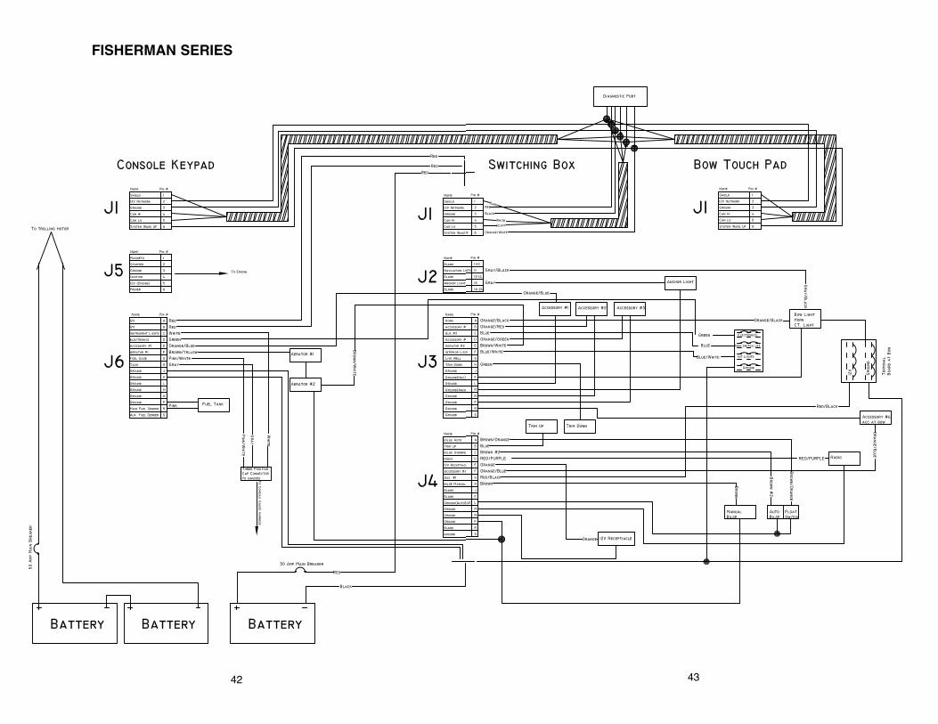
FISHERMAN SERIES
43

SALTWATER MODELS WITH DIGITAL SWITCHING
44 45
474746
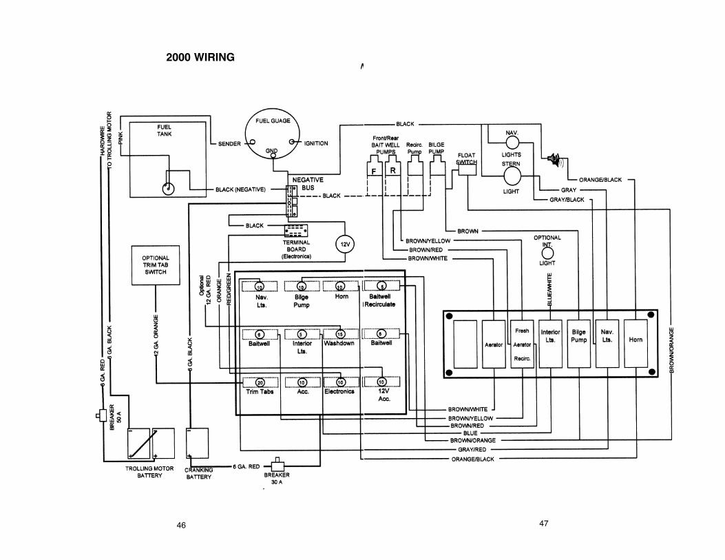
2000 WIRING

4948
Z COMANCHE

Electrical System
ELECTRICAL SYSTEMFUSE PANEL INFORMATION
On some models, the fuse panel is located for easy access andfeatures plug-in type ATC fuses. The fuses can be easily inspected andreplaced. Z Commanche, Fisherman and some Saltwater models haveno replaceable fuses. Circuits are reset as outlined in that modelsElectrical System section.
The Panel has a capacity of twelve to sixteen individual circuits. Theparticular accessory(ies) they operate are shown on the decal on the rightside of the fuse panel of back side of the fuse panel cover.
To improve the performance of the batteries, turn the master breakersto the off position when the boat is not in use. Electronics, stereos andother items that the boat may be equipped with, could have a currentdraw even when those items are turned off. If you leave your boat in thewater, leave the breaker turned on in order for the automatic bilge pumpto have power. If conditions are such that the bilge pump is operatingfrequently, it will be necessary to check the battery for its state of chargeand to charge as needed. On Saltwater models equipped with digitalswitching, you may leave the main breaker and all cut off switches turnedto the off position while the boat is not in use. The auto bilge pump onthese models is connected directly to the battery and fused independentof the main breaker.
50
Do not exceed recommended fuse sizes.Always install proper rated fuse when
adding accessories to the fuse panel.
CAUTION

Electrical System
FISHERMAN SERIES Wake and Sleep Mode
Sleep mode will cause the keypad to reduce power consumption byreducing live circuits. For the keypad to enter the sleep mode it willrequire the main 30 amp breaker to be on, no switch activity for fourhours, all pumps turned off, and the ignition is off. When the keypad is inthe sleep mode the accessories will not function. To wake the keypad youmust press one of the following functions: Start, Stop, 1, 2, 3, 4, or anybutton on the bow touch pad with the main breaker set to the on position.After pressing one of the buttons, you can then proceed with your desiredoperation. While the keypad is in the sleep mode, the float switch to thebilge still has power and if the float switch is triggered, it will wake thekeypad. If the bilge pumps, livewell pumps or the ignition is left on, thesystem will not enter sleep mode.
Keyless IgnitionStarting the engine:• Turn the main breaker to on.• Press on the buttons required to wake the system.• Enter the following user code unless it has not been changed in order
“1-2-3-4”.• Press “Start”. After pressing start the LED by the stop button will light
putting the keyless ignition switch in accessory mode.• Press the “Start” button a second time holding it for two seconds and
the engine will crank.• Once the engine has started, release the “Start” button.• To stop the engine, press the stop button.• To lock the system after stopping the engine, enter the user code “1-2-
3-4” and then press “Stop”.
To choke a carbureted engine:Press the “Start” and the “1” key simultaneously while starting the
engine.
To change the user code:Wake the system up by pressing one of the buttons described above.
Enter in the current user code followed by pressing the “1” and “4” buttonsat the same time. You will have two seconds after entering in the usercode to press the “1” and “4” buttons.
“1-2-3-4” buttons “1” and “4” Leave the “1” and “4” depressed until the stop LED flashes. If the
stop LED does not flash after holding the “1” and “4” down for fiveseconds, one of the following may have happened: the user code was notentered correctly or “1” and “4” was not depressed at the same time, or
51

Electrical System
52
too much time elapsed after entering in the user code before pressing the“1” and “4” . Turn the system off by entering in the code and press stop.After the LED is not lit by the stop button, start at the beginning of thissection again.
After the flashing of the stop LED is obtained, enter in the new fourdigit number followed by the start button, and then re-enter the four digitnumber followed by the start button.
“X-X-X-X” “Start” “X-X-X-X” “Start” After pressing the start button the second time, the system will go into
accessory mode. If it does not enter accessory mode, type the currentuser code in and press the stop button then proceed to the beginning ofthis section.
Navigation LightsThe switch labeled “Nav./Anchor” on the bow and console keypads
controls the operation of the navigation lights. On the first key press, thebow navigation and stern anchor lights will turn on. On the second press,the bow lights will turn off and the anchor light will remain on. On the thirdkey press, the anchor light will turn off.
Aerator SystemThere are two livewell buttons, one labeled “1” and the second
labeled “2”. livewell button “1” is for the main well and “2” for the bait well.Pressing the buttons once will turn on the pump and pressing a secondtime will turn off the pump. While the pumps are running, you can set thelivewell timer for a desired run time for the pumps. The timer can beadjusted in three increments, “L, M, and H”. The “L” setting is 1 minute onand two minutes off. “M” is 5 minutes on and 1 minute off. “H” is 15minutes on and two minutes off.
Fuel System Functioning IndicatorThe LED with the fuel pump located next to it is a fuel functioning
indicator. This LED will tell you if a short is present between the sendingunit and the gauge.
Bilge SystemThe switch labeled with an image of the water leaving the sump of the
boat controls the bilge pumps in the boat. Pressing this button once willactivate a manual bilge pump; pressing again will activate the auto bilgeand the manual bilge; pressing again will turn off all bilge pumps. Theautomatic bilge pump float switch always has power. The float switch islocated in the sump of the boat.
Interior LightsPressing the button with the light bulb activates the interior lights on

Electrical System
53
the boat. Pressing this key 1 time will activate the lights; pressing the keya second time will turn off the lights. If the lights are left on, they willautomatically turn off after five minutes.
Dimming the Instrument Lights and Key Pad LightsIf the boat is equipped with the standard gauges, it is possible to dim
the gauge lights and keypad lights for night driving. First turn the keylessignition to the run position and press the interior light button leaving thebutton depressed. You will see the gauge lights and keypad lightsoscillate from dim to bright. When the desired brightness is obtained,release the interior light button.
AccessoriesThere are five accessory functions labeled “A, ACC, A1, A2, and A3”.
The “A” accessory will drive the oxygenator option. All other accessoriesbuttons will drive any device up to 5 amps. Pressing the button once willturn the accessory on; pressing a second time will turn the accessory off.
HornThe button with the image of a trumpet is the horn button. Pressing
and holding this button will sound the horn; releasing this button will turnthe horn off.
TrimOn the bow keypad, the switch with the up arrow controls the trim up
and the switch with the down arrow controls the trim down. Pressing andholding the button will allow the trim to function. Releasing the button willcause the trim to stop.
Back LightingThe back lighting will illuminate the keypad. After waking up the
system, it will turn on for 60 seconds or while in the wake mode, it will turnon after any key press for 60 seconds.
Resetting a BreakerIf a circuit causes the breaker to throw, it is indicated by a flashing
LED. The LED corresponding to the thrown breaker will flash by its switchalong with the stop LED. If the stop LED is the only LED flashing, one ofthe un-switched outputs (trim, 12V, radio, auto bilge float switch,electronics, or key on engine hot) has thrown a breaker. To reset thebreaker, press the switch leaving it held in for five seconds. If the lightremains flashing there is a direct short present. If the light stops flashing,the breaker has been reset.

Electrical System
SALTWATER SERIESDIGITAL SWITCHES 191, 223, 2000, 2180, 2200, 2300, 2400
Wake-up and Sleep ModeTo reduce power consumption, the keypad and power module can
shutdown their supply. In this mode, however, only the float switch ofautomatic pump is powered. The system is put in wake-up mode whenany key of the keypad is pressed, ignition signal is on, or float switch isactivated.
When main 30A breaker is open, the keypad and power module arenot powered. DC Switching cannot activate its loads.
When the main 30A breaker is closed, the power module and thekeypad are powered. After 4 hours of no switch activity, if livewell pumpsare not in function and engine ignition is not activated, the power moduleand the keypad will go in sleep mode.
Navigation and Anchor LightsThe navigation light switches on keypad control the operation of
navigation and anchor lights. On the first key press of the switch, bothnavigation and anchor lights are turned on. On the second key press ofthe navigation switch, navigation light turn off and anchor light remain on.On the third press of the navigation switch, anchor turns off.The indicatorbrightness will dim when navigation or anchor lights are on.
Aerator SystemThe livewell (labeled 1) and livewell timer switch control the rear
livewell. Pressing the livewell (1) switch on keypad turns on the rear wellfresh pump. Pressing the livewell (1) switch again will close both rear wellfresh pump and rear recirculate pump. When either rear pump is on, thelivewell timer can be used to start a periodic aeration cycle. Pressing thelivewell timer once starts the low aeration cycle of one minute on and twominutes off. On a second key press of the livewell timer, the mediumaeration cycle of five minutes on and two minutes off. When a third pressof livewell timer, the high aeration cycle of 15 minutes on and two minutesoff starts. The fourth key press of livewell timer will turn off the timerfunction. Rear activated pumps only will follow the cycle time.
Bilge SystemThe bilge switch on the keypad controls the bilge system. The float
switch always has power. Pressing the bilge switch once activates thebilge pump by overriding the float switch. Pressing the switch a second
54

Electrical System
time deactivates the override output.Accessories
There are four accessory functions labeled A1 (optional bilge pump),A2 (optional washdown), A3 (optional aerator), and A4 (optional radio).Pressing the corresponding switch will turn on that accessory.
HornPressing and holding the switch activates the horn. Release the
switch for stopping the horn.
Interior Light(s)Pressing the interior light switch will turn on that accessory. Pressing
the switch again will turn off the accessory.
Instrument Light(s)The instrument light output is activated when the ignition input
receive a +12V signal. Instrument light, keypad status LED andbacklighting LED level can be adjusted by pressing and holding theinstrument light switch.
Back LightingThe back lighting is activated when module is awake and dimmed
down when nav. light, anchor light or instrument light is activated.
Function Switch Open BreakerIf function switch breaker is open, corresponding LED will flash.
Press and hold switch for five seconds to close breaker. Find fault, ifproblem arises again.
Unswitched Outputs 1 to 4These outputs are activated when main breaker is closed and system
is awake. Since these outputs do not have associated switches andLEDs, horn LED will indicate failure by flashing. Pressing the horn switchfor five seconds will reset the four unswitched breakers.
55

Z COMANCHE
Wake and Sleep ModeSleep mode will cause the keypad to reduce power consumption
by reducing live circuits. For the keypad to enter the sleep mode, it willrequire the main 30 amp breaker to be on and no switch activity for fourhours, all pumps turned off and the ignition is off. When the key pad is inthe sleep mode, the accessories will not function. To wake the keypad,you must press one of the following functions: Start, Stop, 1, 2, 3, 4 or anybutton on the bow touch pad with the main breaker set to the on position.After pressing one of the buttons, you can then proceed with your desiredoperation. While the keypad is in the sleep mode, the float switch to thebilge still has power and if the float switch is triggered, it will wake thekeypad. If the bilge pumps, livewell pumps, or ignition is left on, thesystem will not enter sleep mode.
Keyless IgnitionStarting the engine:• Turn the main breaker to on.• Press on the buttons required to wake the system.• Enter the following user code unless it has not been changed in order
“1-2-3-4”.• Press “Start”. After pressing start the LED by the stop button will light
putting the keyless ignition switch in accessory mode.• Press the “Start” button a second time holding it for two seconds and
the engine will crank.• Once the engine has started, release the “Start” button.• To stop the engine, press the stop button.• To lock the system after stopping the engine, enter the user code “1-2-
3-4” and then press “Stop”.
To choke a carbureted engine:Press the “Start” and the “1” key simultaneously while starting the engine.To change the user code:
Wake the system up by pressing one of the buttons described above.Enter in the current user code followed by pressing the “1” and “4” buttonsat the same time. You will have two seconds after entering in the usercode to press the “1” and “4” buttons.
“1-2-3-4” “1” and “4” Leave the “1” and “4” depressed until the stop LED flashes. If the
stop LED does not flash after holding the “1” and “4” down for fiveseconds, one of the following may have happened: the user code was not
56
Electrical System

Electrical System
entered correctly or “1” and “4” was not depressed at the same time, ortoo much time elapsed after entering in the user code before pressing the“1” and “4” . Turn the system off by entering in the code and press stop,after the LED is not lit by the stop button. Start at the beginning of thissection again.
After the flashing of the stop LED is obtained, enter in the new fourdigit number followed by the start button, and then re-enter the four digitnumber followed by the start button.
“X-X-X-X” “Start” “X-X-X-X” “Start” After pressing the start button the second time, the system will go into
accessory mode. If it does not enter accessory mode, type the currentuser code in and press the stop button, then proceed to the beginning ofthis section.
Navigation LightsThe switch labeled “Nav./Anchor” on the bow and console keypads
controls the operation of the navigation lights. On the first key press, thebow navigation and stern anchor lights will turn on. On the second press,the bow lights will turn off and the anchor light will remain on. On the thirdkey press, the anchor light will turn off.
Aerator SystemPressing the livewell key will activate two aerator pumps; pressing
this button again will turn off the aeration pumps. Pressing the livewelltimer button will automatically turn on the aeration pumps and the timerin the “L” setting. The timer can be adjusted in three increments - “L, M,and H”. The “L” setting is one minute on then two minutes off. “M” is fiveminutes on and one minute off. “H” is 15 minutes on and two minutes off.
Fuel LevelThe switch labeled with an image of a fuel pump on the console
keypad controls which tanks’ fuel will be displayed by the fuel gauge.When the switch is pressed it will toggle between tank 1 and tank 2. Tank1 will be on the starboard side and 2 will be on the port side. On modelswith only 1 fuel tank, the number 2 position will cause the gauge to readempty.
Bilge SystemThe switch labeled with an image of the water leaving the sump of the
boat controls the bilge pumps in the boat. Pressing this button once willactivate a manual bilge pump; pressing again will activate the auto bilgeand the manual bilge; pressing again will turn off all bilge pumps. Theautomatic bilge pump float switch always has power. The float switch islocated in the sump of the boat.
57
Electrical System
Interior LightsPressing the button with the light bulb activates the interior lights on
the boat. Pressing this key one time will activate the lights; pressing thekey a second time will turn off the lights. If the lights are left on, they willautomatically turn off after five minutes.
Dimming the Instrument Lights and Keypad LightsIf the boat is equipped with the standard gauges, it is possible to dim
the gauge lights and keypad lights for night driving. First turn the keylessignition to the run position and press the interior light button leaving thebutton depressed. You will see the gauge lights and keypad lightsoscillate from dim to bright. When the desired brightness is obtained,release the interior light button.
AccessoriesThere are five accessory functions labeled “A, ACC, A1, A2 and A3”.
The “A” accessory will drive the oxygenator option. All other accessorybuttons will drive any device up to 5 amps. Pressing the button once willturn the accessory on; pressing a second time will turn the accessory off.
HornThe button with the image of a trumpet is the horn button. Pressing
and holding this button will sound the horn; releasing this button will turnthe horn off.
TrimOn the bow keypad, the switch with the up arrow controls the trim-up
and the switch with the down arrow controls the trim down. Pressing andholding the button will allow the trim to function. Releasing the button willcause the trim to stop.
Back LightingThe back lighting will illuminate the keypad. After waking up the
system, it will turn on for 60 seconds or while in the wake mode, it will turnon after any key pressed for 60 seconds.
Resetting a BreakerIf a circuit causes the breaker to throw, it is indicated by a flashing
LED. The LED corresponding to the thrown breaker will flash by its switchalong with the stop LED. If the stop LED is the only LED flashing, one ofthe un-switched outputs (trim, 12V, radio, auto bilge float switch,electronics, or key on engine hot) has thrown a breaker. To reset thebreaker, press the switch in, leaving it held in for five seconds. If the lightremains flashing, there is a direct short present. If the light stops flashing,the breaker has been reset.
58

Electrical System
INSTALLATION OF 4 PRONG “TYPE IV” PLUG TO TROLLINGMOTOR AND BATTERY CHARGER
The Type IV plug is not designed for direct attachment to bare wires.All wires must be terminated with a #10 ring terminal of the appropriatewire gauge size. When assembling plug, insure that two cover screwspass through grooves in plug body.
59
Always disconnect trolling motor plugprior to any direct charging to any battery
in the rear storage area.
CAUTION

Electrical System
60

Electrical System
SAFETY AND MAINTENANCE TIPS
�� Check battery connections periodically to make sure they arecorrosion free and TIGHT.
�� Alterations of any part of the wiring system should be avoided! Suchalterations could cause damage and/or electrical short.
�� Inspect wiring connections and terminals periodically for corrosion,etc. and replace as needed. Replacement components should alwaysbe of equal or greater rating and quality. We recommend Rangerreplacement parts available through your Ranger dealer.
�� Always disconnect the positive and negative leads from the batteryterminals before installing, removing, servicing, or troubleshootingany part of the electrical system.
61

Federal Requirements for Recreational Boats
62
EQUIPMENT
Whistle orHorn
VisualDistress
Lights
Fire Extinguishers
PFD’S
Numbering
Certificate ofNumber
Display ofNumber
CLASS A(Under 16’ in Length)
CLASS I(16’ , but under 26’)
Must have means of making an efficient sound signal.
None Required DuringDaytime
Proper light displays are required to be shown fromsunset to sunrise.
All recreational boats, whenused on coastal waters, whichincludes the Great Lakes, theTerritorial Seas, and thosewaters directly connected to theGreat Lakes and the TerritorialSeas, up to a point where thewaters are less than two mileswide, must be equipped withvisual distress signals.
One B-1 U.S.C.G. or U.L. approved fire extinguisherunless the construction is such that explosiveflammable vapors cannot be trapped, there are noclosed compartments, no permanently installed fueltanks on board.Type I, II, III, or V foreach person aboard.
Type I, II, III, or V for eachperson aboard and one TypeIV.
All undocumented vessels equipped with propulsionmachinery must be numbered in the state of principleuse.
A valid certificate of number showing the numbersissued to a vessel must be on board whenever thevessel is in use.
Number must be painted or permanently attached toeach of the forward halves of the vessel, and no othernumber may be displayed thereon.
NOTE: The above information is not conclusive. The owner/operatorshould check all current Federal, State, and Local Regulationsto insure compliance.

Federal Requirements for Recreational Boats
Boat operators are required to file a boating accident report with theirstate boating law enforcement agency when their boat is involved incertain boating accidents as follows:
1) There is loss of life or probable loss of life.
2) Personal injury requiring medical treatment (other than first aid).
3) Damage to property that exceeds $500.
63

BOAT DATA
OWNER
Address
DEALER
Address
Phone
BOAT - MAKE/MODEL
Serial No.
Key No.
ENGINE - MAKE/MODEL
Serial No.
Drive Unit Serial No.
OTHER
64

Your RangerTrail® Trailer
GENERAL INFORMATION AND MAINTENANCE
�� Keep the hubs properly lubricated at all times as described in the hubsection of this manual.
�� Check all lights before each use of the trailer.�� Check the tires for wear, cuts or other damage before each use and
replace as needed. Check tire pressure often. See tire sidewall formaximum pressure and maximum load.
�� Check lug nuts for tightness before use. Torque lug nuts to 85 ft. lbs.�� Periodically check the winch strap and winch parts for any wear and
replace worn parts.�� Remember… a small expense for preventive maintenance is much
less expensive now than a road-side breakdown later!
Steps for Determining Correct Load Limit(1) Locate the statement “The weight of cargo should never exceed XXX
kg or XXX lbs.” on your vehicles placard.(2) This figure equals the available amount of cargo and luggage load
capacity.(3) Determine the combined weight of cargo and gear being loaded on
the trailer. That weight may not safely exceed the available cargo andluggage load capacity.
65
Trailer tires should be properly inflatedand maintained! The load-carrying
capacity of your trailer is based on the tire pressure. Inadequate tirepressures can void your tire and trailer warranty and could also lead toan accident damaging to people or equipment!
CAUTION
Lug nuts should be properly tightenedbefore each use. Failure to do so could
result in loss of a wheel and could lead to an accident causing injury ordeath.
WARNING

Your RangerTrail® Trailer
CONTAINED OIL ORBITAL LUBRICATION (COOL) HUBS
COOL Hubs should be serviced once a year or every 20,000 mileswhichever comes first.
1. Jack up the trailer and remove the wheel.2. Remove oil filling plug from COOL hub.3. Turn hub so all oil drains from cavity.4. Add 2.5 - 3 ounces 50 wt motor oil until level is approximately full
(up to Max. Fill Line).5. Replace oil fill plug.6. Check oil level before each trip and maintain level to “MAX FILL” line
on center cap.If your trailer has the rubber fill plug in the center of the amber cap, the
following procedure is required:7. Remove wheel center if wheel has one. Do not jack up the trailer or
remove tire. Using a piece of cardboard and a catch pan, with thecardboard under the amber center cap, remove the center cap andlet oil drain on cardboard into catch pan. Once drained and rubberplug removed from amber center cap, re-install the amber centercap till seated on hub. Fill to bottom of fill hole; wait 10 minutes andrefill to bottom of hole with oil and install rubber plug. This time isneeded for the oil to seep through the bearings so proper level willbe shown.
8. Reinstall wheel, tightening lug nuts to 85 ft. lbs. NOTE: It is normal for the oil to change color after a few miles of use.9. Dispose of oil soaked cardboard and used oil in an appropriate
manner.
66
Your RangerTrail® Trailer
COOL HUB ADDENDUM
2007 model Ranger COOL Hubs now have a 3 year “No Touch”warranty. There is no required maintenance for three years from theoriginal date of purchase. If for some unforeseen reason the hubdevelops an oil leak, it will be replaced free of charge. Please note thatthe color of the oil will change over time and does not indicate a problemthat requires any action.
After three years the hub needs to be serviced by draining and refillingwith 50 wt oil.
66.1

Your RangerTrail® Trailer
TRAILER BRAKESIf your trailer is equipped with brakes, follow the safety and
maintenance tips listed below for best service.�� Always hook up the brake breakaway cable securely to the tow
vehicle (should the trailer come loose, cable will activate the brakesto help slow runaway trailer). Before towing, make sure that theemergency breakaway cable has not been inadvertently set byseeing that the button stop is not showing (see figure 15). Reset tonormal position by prying spring with a screwdriver and reinsertingcable. Always insert hitch pin after latching coupler to trailer ball.
�� Disc brake trailers are equipped with an electric solenoid valve toprevent the disc brakes from being activated while reversing yourtrailer. Disc brakes will operate at full capacity in either direction. It istherefore, essential that the wire from the solenoid valve beconnected to the reverse light wire of the tow vehicle. When the towvehicle is put in reverse gear, the solenoid will deactivate the brakesand allow you to back up (Fig. 16 page 68).To check proper operation of solenoid valve, place tow vehicle gearshift in reverse (with engine shut off and ignition on). Backup lightsshould turn on and an audible “click” should be heard at the valve. Iflights come on and no “click” is heard, check for an electrical wiring orconnection problem.
�� Check cap of master cylinder often for tightness.
�� Follow routine maintenance and inspection for disc brakes as outlinedin your Disc Brake Manual.
To minimize corrosion, it is necessary for the disc brake calipers androtors to be rinsed off with fresh water after trailer has been immersed insalt water.
INSPECTION
To assure continued proper operation of our trailer disc brakes, annualinspection is recommended.
67
Make sure back up lights do not comeon when tow vehicle transmission is in
any gear other than reverse.
CAUTION

Your RangerTrail® Trailer
68
FIG. 16

Your RangerTrail® Trailer
PADS
Pads must be replaced when 1/16 inch (0.060”) of pad friction materialis left.
ROTORS
Rotors should be resurfaced by a qualified brake specialist if extremegalling or wear marks are present.
RUST
Check for extreme rust on mounting bolts, flanges and welds, whichmay weaken the structural integrity of the system. Repair or replace asnecessary.
LEAKS
REPLACEMENT PARTS
All replacement parts may be purchased from Tie Down Engineering,5901 Wheaton Drive, Atlanta, GA 30336. If you have any questions orproblems with your brake or axle systems, you may contact Tie DownEngineering at 404-344-0000 or visit their website at www.tiedown.com.
69
If not familiar with disc brake padreplacement, have work performed by a
qualified individual or service shop.
CAUTION
Rotors must be replaced if distancebetween brake surfaces becomes less
than 0.850 inches (21.6 mm) due to wear or machining.
CAUTION
Check for leaks in the brake lines andfittings. Leaks will lead to loss of trailer
braking ability. Repair or replace as necessary.
CAUTION
The braking mechanism on this trailer isdesigned as an aid in slowing and
stopping the trailer. The braking system on the tow vehicle is theprimary slowing and stopping system. You will not be able to stop thetow vehicle and the towed trailer as quickly as you could stop the towvehicle alone.
WARNING
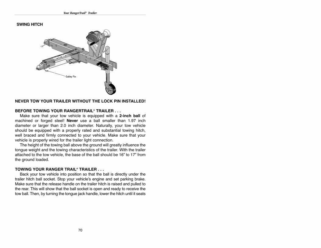
Your RangerTrail® Trailer
70
NEVER TOW YOUR TRAILER WITHOUT THE LOCK PIN INSTALLED!
BEFORE TOWING YOUR RANGERTRAIL® TRAILER . . .Make sure that your tow vehicle is equipped with a 2-inch ball of
machined or forged steel! Never use a ball smaller than 1.97 inchdiameter or larger than 2.0 inch diameter. Naturally, your tow vehicleshould be equipped with a properly rated and substantial towing hitch,well braced and firmly connected to your vehicle. Make sure that yourvehicle is properly wired for the trailer light connection.
The height of the towing ball above the ground will greatly influence thetongue weight and the towing characteristics of the trailer. With the trailerattached to the tow vehicle, the base of the ball should be 16” to 17” fromthe ground loaded.
TOWING YOUR RANGER TRAIL® TRAILER . . .Back your tow vehicle into position so that the ball is directly under the
trailer hitch ball socket. Stop your vehicle’s engine and set parking brake.Make sure that the release handle on the trailer hitch is raised and pulled tothe rear. This will show that the ball socket is open and ready to receive thetow ball. Then, by turning the tongue jack handle, lower the hitch until it seats
SWING HITCH

Your RangerTrail® Trailer
fully on the tow ball. Be sure that the tongue jack wheel is slightly clear ofthe ground. Close the ball socket latch by pushing downward into therecess. The release handle should close smoothly if the ball has beenseated correctly into the socket. If the release handle does not close, DONOT TOW THE TRAILER. Insert safety pin through hole. To make surethat the connection is secure, lower the tongue jack until the ram haslifted the trailer hitch and trailer tongue connection 3 or 4 inches. If the balldoes not disengage, you may be reasonably sure that the attachment issecure.
Next, fully retract the jack into the full up position and latch. Connectthe safety chains to the connection points on your tow vehicle hitch.
If your trailer is equipped with brakes, hook up the emergencybreakaway cable and inspect to see that the breakaway cable button stopis not showing. Please refer to your brake owners manual. If you do nothave a brake system manual, please write or call Tie Down Engineering,5901 Wheaton Drive, Atlanta, GA 30336, 404-344-0000.
On swing hitch trailers, make sure the hitch is in the forward positionand the locking pin is properly installed. Connect your trailer wire harnessand test your vehicle lights to make sure that the trailer’s brake and turnsignals duplicate your vehicles. Remove any trailer wheel chock andcarefully pull away.
To unhitch your trailer from the tow vehicle, place the trailer on a leveland paved surface and chock both trailer wheels to prevent anymovement forward or backward. Unhook the safety chains, wiringharness and, if so equipped, the brake break-away cable. Then, using thetrailer tongue jack, raise the hitch up and clear the ball. In this position thetrailer tongue should be left somewhat bow high so that any water will runout through the drain hole in the stern of the boat.
71
Retract jack fully before towing! Replacecoupler and ball if worn… do not attempt
repair or adjustment.
CAUTION
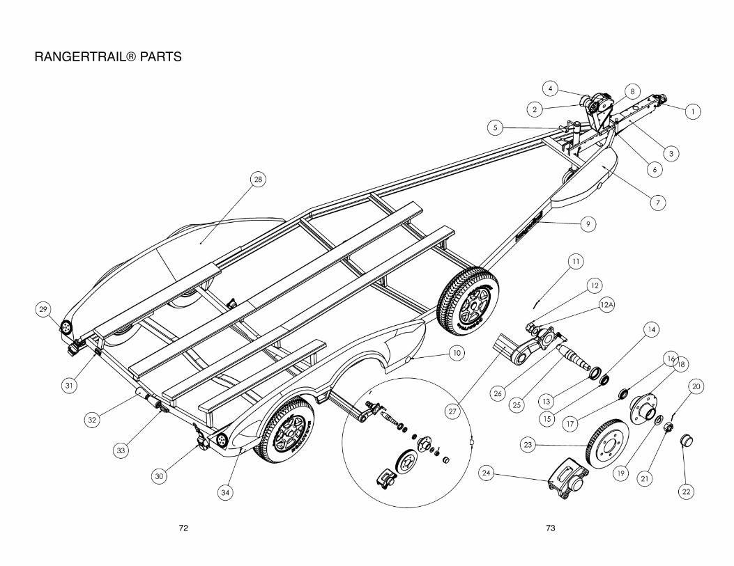
73
RANGERTRAIL® PARTS
72

RANGERTRAIL® PARTS LIST
74
# DESCRIPTION
1. Brake Hitch2. Bow Roller 3. Lower Winch Stand4. Winch5. Swing Jack6. Upper Winch Stand7. Fiberglass Step8. Lock Pin9. Rangertrail Decal
10. Side Marker Light Amber11. Inside Cotter Pin12. Castle Nut12.a Washer13. Spindle14. Inside Bearing15. Inside Bearing Race16. Outside Bearing Race17. Outside Bearing18. Hub19. Spindle Washer20. Spindle Nut Cotter Pin21. Spindle Nut22. Hub Oil Cap23. Disc Brake Rotor24. Disc Brake Caliper25. Oil Seal26. Lug Bolt27. Torsion Axle 28. Carpeted Fender Board29. Stop / Turn Light30. Ratchet Tie Down31. License Plate Light32. Keel Roller33. Clearance Light Red34. Side Marker Red Light

WWOOOODD MMAANNUUFFAACCTTUURRIINNGG CCOOMMPPAANNYY,, IINNCC.. LLIIMMIITTEEDD WWAARRRRAANNTTYYRRAANNGGEERR®® BBOOAATTSS AANNDD RRAANNGGEERRTTRRAAIILL®® TTRRAAIILLEERRSS
LLIIMMIITTEEDD WWAARRRRAANNTTYY
““WWoooodd MMaannuuffaaccttuurriinngg CCoo..,, IInncc..,, ((““WWoooodd””)), warrants to you, the first North American retailpurchaser of this 2007 model year boat delivered by a factory authorized dealer, that it will repairor replace defects in materials or workmanship that occur within the applicable warranty periods,subject to the “What This Warranty Does Not Cover” section below. The applicable WarrantyPeriod runs from the date of delivery to the first retail customer provided that the boat is deliveredwithin twenty four (24) months from the date of manufacture. For boats delivered more thantwenty four (24) months after the date of manufacture, coverage will run from the date ofmanufacture and the first retail purchaser will be entitled to the coverage remaining under theWarranty Periods. All warranties run concurrently.
Defects in structural parts, including the hull, stringers and transom: Warranty Period runs for theduration of the original (1st) purchaser’s period of ownership. The transferred Warranty Periodto a 2nd purchaser runs ten (10) years from the original delivery date, regardless of when thewarranty is transferred.
Defects in the following factory installed parts and components: Warranty Period runs for three(3) years.
1. Carpet fade2. Steering helm, cylinder, hoses and cables3. Aeration pumps and valves4. Bilge pump 5. Boat electrical system 6. Seat pedestals7. Fuel tanks8. Deck hardware such as locks, cleats and fasteners9. Factory installed battery charger
10. RangerTrail® trailer
Remaining factory installed parts and components: Warranty Period runs one (1) year from thedate of delivery to the original retail purchaser.
Defects in the exterior cosmetic gelcoat finish (cracking, crazing or fading): Warranty Period runsone (1) year from the date of delivery to the original retail purchaser. Repairs will only beauthorized after Wood is satisfied that there is a defect in material or workmanship.
Coverage remaining under the Warranty Periods may be transferred by an authorized Ranger®dealer to a 2nd purchaser for a $100 fee. The transfer must occur within five (5) years of theoriginal retail sale. The transfer fee must be paid within 15 days of purchase of the used boat totransfer the warranty. Proof of purchase date is required. The warranty may only be transferredonce.
Your sole and exclusive remedy is the repair or replacement, at Woods sole option, of parts andcomponents covered by this warranty.This Ranger® boat, including any alleged defective part, must be returned to an authorizedRanger® dealer within the applicable warranty period to obtain warranty service. The Ranger®dealer will carry out the warranty procedures on the owner’s behalf. All warranty work will beperformed at an authorized dealer, at the Wood factory, or at another repair facility that Woodselects. The owner is responsible for the expense associated with transporting the boat to andfrom the repair facility.
An action for breach of warranty shall be barred unless it is commenced within four (4) years fromthe date the cause of action accrues. An action for breach of any duty or obligation to repair orreplace shall be barred unless it is commenced within one year from the date the cause of actionaccrues regardless of the time remaining in the Warranty Period.
75
What This Warranty Does Not Cover:
1. A boat including its components that has been altered or modified so as to adverselyaffect its operation, performance or durability.
2. Any damage resulting from an impact with another object.
3. Windshield breakage and leakage around windshields, hatches or other designedopenings.
4. Gelcoat finishes including blistering, cracking, crazing, fading, chalking or discoloration(except as noted above).
5. Carpet and upholstery wear, fraying or tearing.
6. A boat which has been overpowered according to the maximum recommended enginehorsepower specified on the capacity plate.
7. A boat with an engine setback that is in excess of six (6) inches, or ten (10) inches on aZ Comanche and Bay Ranger.
8. Estimated characteristics such as weight, speed and fuel consumption.
9. Any boat which has been misused, used in a negligent manner, used for racing, used forrental or other commercial purposes, used without normal maintenance, operatedcontrary to any instruction furnished by Wood, involved in an accident or operated inviolation of any Federal, State, Coast Guard or other governmental agency laws, rules orregulations.
10. Loss of time, inconvenience, boat payments, retail charges, travel expense, loss of use,haul out, launch, towing and storage charges, loss of or damage to personal property, orother remedies not specifically allowed.
11. Dealer preparation, cleaning, final adjustments and alignments in preparing the boat fordelivery.
12. Trailer tires, paint chipping, rust/corrosion, axle alignment and trailer componentsmanufactured by companies other than Wood.
13. Engines, outdrive, controls, propellers, batteries and other equipment or accessories thatare not manufactured by Wood, whether or not warranted by other manufacturers.
Remedy under this warranty is expressly limited to repair or replacement of defects in materialsor workmanship, aanndd ddooeess nnoott iinncclluuddee iinncciiddeennttaall oorr ccoonnsseeqquueennttiiaall ddaammaaggeess, which arespecifically DDIISSCCLLAAIIMMEEDD. Note: SOME STATES DO NOT ALLOW THE EXCLUSION ORLIMITATION OF INCIDENTAL OR CONSEQUENTIAL DAMAGES, SO THE ABOVELIMITATION OR EXCLUSION MAY NOT APPLY TO YOU. The express limited warrantydescribed above is exclusive. IMPLIED WARRANTIES (IF ANY), IINNCCLLUUDDIINNGGMMEERRCCHHAANNTTAABBIILLIITTYY AANNDD FFIITTNNEESSSS FFOORR AA PPAARRTTIICCUULLAARR PPUURRPPOOSSEE, ARE LIMITED INDURATION TO THE APPLICABLE PERIOD OF THIS WRITTEN WARRANTY AND AREEXPRESSLY DISCLAIMED AFTER THE EXPIRATION OF THE WARRANTY PERIOD. Thereare no warranties which extend beyond the description on the face hereof. NNOOTTEE:: SOMESTATES TO NOT ALLOW LIMITATION ON HOW LONG AN IMPLIED WARRANTY LASTS, SOTHE ABOVE LIMITATION MAY NOT APPLY TO YOU. THIS WARRANTY GIVES YOUSPECIFIC LEGAL RIGHTS WHICH VARY FROM STATE TO STATE.
This document contains the entire warranty given by Wood. Wood does not authorize anyperson or persons, including Ranger® dealers, to change the terms of this express limitedwarranty, which is Wood’s only warranty. Wood reserves the right to change or improve thedesign or manufacture of Ranger® boats without obligation to modify any boat previouslymanufactured.
Wood Manufacturing Company, Inc.Highway 178 North • P.O. Box 179
Flippin, AR 72634870.453.2222
76

MAINTENANCE NOTES
77

78
MAINTENANCE NOTES