Embed Size (px)
Citation preview
Four Ways To Introduce Structure in Fluidized Bed Reactors
J. Ruud van Ommen,* John Nijenhuis, Cor M. van den Bleek, and Marc-Olivier Coppens
Delft UniVersity of Technology, DelftChemTech, Julianalaan 136, 2628 BL Delft, The Netherlands
Just like for fixed bed reactors, the rational structuring of fluidized beds is interesting from the point of viewof process intensification. Structuring can facilitate scale-up and increase conversion and selectivity bycontrolling the size and the spatial distribution of the bubbles. We present four approaches to structure fluidizedbeds: oscillating the gas flow, imposing an electric field to induce interparticle forces, distributing the gasinjection, and optimizing distributed particle properties such as particle size. Experimentally, we show thatthese methods can indeed lead to a drastic reduction of the bubble diameter in bubbling fluidized beds for arange of operating conditions. For two methodologies, imposing an electric field and distributing the gasinjection, also a considerable increase in conversion is demonstrated.
Introduction
At present, many catalyzed gas-phase reactions in thechemical industry are carried out in packed beds. These reactorsare relatively easy to design and operate (i.e., investment andoperational costs are low), but disadvantages include maldis-tribution, a large pressure drop over the bed, and sensitivity tofouling by dust.1 A prominent tradeoff in packed beds is relatedto the particle size. Small particles are often desired for maximalcatalyst effectiveness, which impacts activity, selectivity, andstability alike. However, smaller particles also lead to anincreased pressure drop. At some point, the pressure drop simplybecomes too high for practical purposes.2 It is expected thatcatalysts will become more efficient in the coming years,because of the new opportunities offered by molecular modeling,the use of high-throughput techniques in catalysis engineering,and advances in synthesis methods.3-5 This will lead to evenmore severe mass and heat transfer problems in packed beds.Therefore, a shift from beds of randomly packed particles toreactors with shorter diffusion lengths will be needed.
The use of structured packings, such as monoliths, is oneway to tackle these problems. Structuring reaction environmentsintroduces extra degrees of freedom allowing decoupling ofconflicting design objectives, such as high mass transfer versuslow pressure drop. Over the past years, Jacob Moulijn and hisco-workers have played a leading role in the research onstructured packings and monoliths in particular.6-13 This paperpays homage to Professor Moulijn on the occasion of hisretirement from Delft University of Technology.
Fixed bed reactors are less suitable for processes in whichregular catalyst replacement is needed, for example, becauseof catalyst deactivation. Moreover, it is not always possible totransfer enough heat to or from these reactors. In those cases,a mobile catalyst phase is desirable, and gas-solid fluidizedbeds are often a good choice. Normally, fluidized beds arechaotic systems, but we will show that, as for packed beds, itis possible to introduce a regular structure in fluidized beds aswell.
Despite their good heat transfer and short diffusion lengths,traditional (i.e., unstructured) fluidized beds have seriousdrawbacks, the two most important ones being their difficultscale-up14-16 and their inefficient use of reactant gas as a resultof the formation of bubbles.17,18 The rather small particles
(diameters on the order of 100µm) used in fluidized beds almostalways ensure the absence of mass transfer limitations insidethe particles. At larger scales, however, mass transfer limitationsare present in many fluidized bed processes, especially in thebubbling but also in the turbulent regime. Because of the masstransfer resistance between the dense and the dilute phase (thevoids or “bubbles”), the reactant conversion in the dilute phaseis much lower than in the dense phase (see Figure 1). This leadsto a low overall conversion, because for fluidized beds of smallparticles the dilute phase conversion dictates the overallconversion. A reduction in bubble size and/or an increase inparticle content of the bubbles will lead to a much smallerdifference in conversion between the two phases and a muchhigher overall conversion, as is illustrated by calculations withthe Kunii and Levenspiel19 model for a simple first-orderreaction (Figure 1). Moreover, in case of a more complexreaction scheme (as in almost every realistic situation) thenarrower residence time distribution resulting from a lowerconcentration difference between the phases typically leads toa higher selectivity toward the desired product.
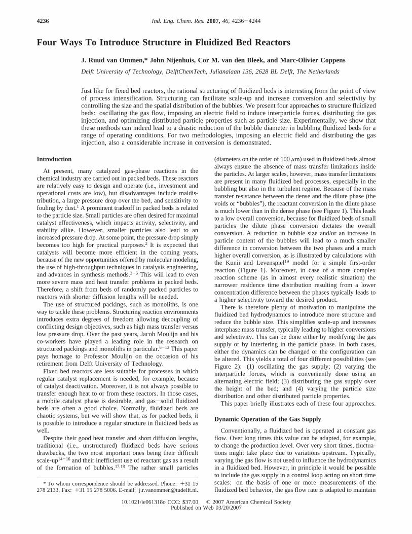
There is therefore plenty of motivation to manipulate thefluidized bed hydrodynamics to introduce more structure andreduce the bubble size. This simplifies scale-up and increasesinterphase mass transfer, typically leading to higher conversionsand selectivity. This can be done either by modifying the gassupply or by interfering in the particle phase. In both cases,either the dynamics can be changed or the configuration canbe altered. This yields a total of four different possibilities (seeFigure 2): (1) oscillating the gas supply; (2) varying theinterparticle forces, which is conveniently done using analternating electric field; (3) distributing the gas supply overthe height of the bed; and (4) varying the particle sizedistribution and other distributed particle properties.
This paper briefly illustrates each of these four approaches.
Dynamic Operation of the Gas Supply
Conventionally, a fluidized bed is operated at constant gasflow. Over long times this value can be adapted, for example,to change the production level. Over very short times, fluctua-tions might take place due to variations upstream. Typically,varying the gas flow is not used to influence the hydrodynamicsin a fluidized bed. However, in principle it would be possibleto include the gas supply in a control loop acting on short timescales: on the basis of one or more measurements of thefluidized bed behavior, the gas flow rate is adapted to maintain
* To whom correspondence should be addressed. Phone:+31 15278 2133. Fax:+31 15 278 5006. E-mail: [email protected].
4236 Ind. Eng. Chem. Res.2007,46, 4236-4244
10.1021/ie061318o CCC: $37.00 © 2007 American Chemical SocietyPublished on Web 03/20/2007
a desired state. Some first steps in this direction were made,20-22
but it is very difficult to obtain instantaneous information aboutthe size and position of tens to hundreds of bubbles in anindustrial fluidized bed. It seems to be a long way before thiskind of closed-loop of feedback control can be applied toindustrial installations.
An alternative to feedback control is to impose a continuousperiodic variation on the gas flow rate. In this way, additionaldegrees of freedom are obtained: amplitude, frequency, andwave shape can now be chosen. It is known that pulsing thegas,23,24 as well as oscillating the distributor plate,25 can causeconsiderable changes in the fluid bed hydrodynamics andsignificantly improve reactor performance.26 Furthermore, cha-otic and other strongly nonlinear systems may turn periodic byoscillating a characteristic (order) parameter. This explainsripples on sand beaches, and many other regular patterns seenin nature. Coppens et al.27 showed that by oscillating the gasflow introduced through the porous bottom distributor plate,bubble patterns in fluidized beds may indeed become orderedand periodic.
Experiments were carried out in two quasi-two-dimensionalbeds. The first one is 15 cm wide, 1.0 cm thick, and 43 cmhigh; the second one is 40 cm wide, 1.5 cm thick, and 43 cm
high. A two-dimensional (2D) bed is convenient for the studyof bubble dynamics, because bubbles are clearly visible. A lightsource was placed behind the 2D beds, to record clear imagesof the bubble pattern on video. The video recordings werecarried out with a frame rate of 25 frames per second; recordingtimes were typically about 2 min.
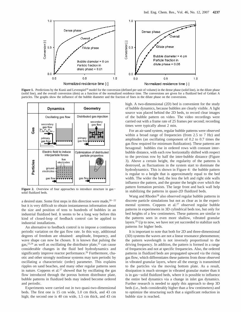
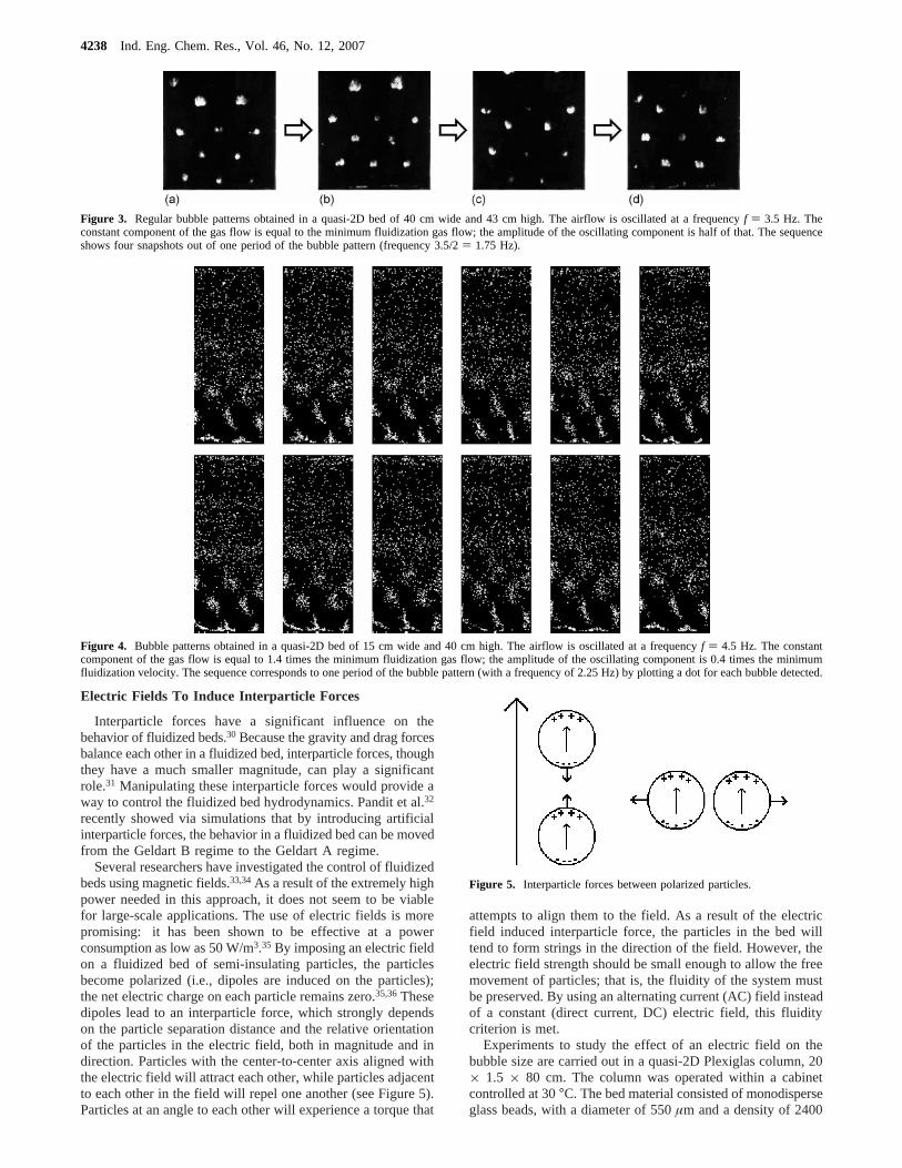
For an air-sand system, regular bubble patterns were observedwithin a broad range of frequencies (from 2.5 to 7 Hz) andamplitudes (an oscillating component of 0.2 to 0.7 times thegas flow required for minimum fluidization). These patterns arehexagonal: bubbles rise in ordered rows with constant inter-bubble distance, with each row horizontally shifted with respectto the previous row by half the inter-bubble distance (Figure3). Above a certain height, the regularity of the patterns isdestroyed, as fluctuations in the system start to dominate thehydrodynamics. This is shown in Figure 4: the bubble patternis regular to a height that is approximately equal to the bedwidth. The wider the bed, the less the left and right side wallsinfluence the pattern, and the greater the height over which thepattern formation persists. The large front and back wall helpin stabilizing the patterns in quasi-2D fluidized beds.
Wang and Rhodes28 also observed regular bubble patterns indiscrete particle simulations but not as clear as in the experi-mental systems. Coppens et al.27 observed regular bubblepatterns in experiments in 3D cylindrical beds too, but only forbed heights of a few centimeters. These patterns are similar tothe patterns seen in even more shallow, vibrated granularlayers.29 Up to now, we have not yet succeeded to stabilize suchpatterns for higher beds.
It is important to note that both for 2D and three-dimensional(3D) systems the waves are not a linear resonance phenomenon;the pattern wavelength is not inversely proportional to thedriving frequency. In addition, the pattern is formed in a rangeof frequencies and not at specific frequencies. Also, the orderedpatterns in fluidized beds are propagated upward via the risinggas flow, which differentiates these patterns from those observedin vibrated granular layers, where all the energy is transmittedto the particles via the moving bottom plate. As a result,dissipation is much stronger in vibrated granular matter than itis in gas-solid fluidized beds, where it is possible to influencethe entire bed dynamics via a change in inlet gas dynamics.Further research is needed to apply this approach to deep 3Dbeds (i.e., beds considerably higher than a few centimeters) andto optimize the structuring such that a significant reduction inbubble size is reached.
Figure 1. Predictions by the Kunii and Levenspiel19 model for the conversion (defined per unit of volume) in the dense phase (solid line), in the dilute phase(solid line), and the overall conversion (dots) as a function of the normalized residence time. The conversions are given for a fluidized bed of Geldart Aparticles. The graphs show the influence of the bubble diameter and the fraction of fines in the dilute phase on the conversions.
Figure 2. Overview of four approaches to introduce structure in gas-solid fluidized beds.
Ind. Eng. Chem. Res., Vol. 46, No. 12, 20074237
Electric Fields To Induce Interparticle Forces
Interparticle forces have a significant influence on thebehavior of fluidized beds.30 Because the gravity and drag forcesbalance each other in a fluidized bed, interparticle forces, thoughthey have a much smaller magnitude, can play a significantrole.31 Manipulating these interparticle forces would provide away to control the fluidized bed hydrodynamics. Pandit et al.32
recently showed via simulations that by introducing artificialinterparticle forces, the behavior in a fluidized bed can be movedfrom the Geldart B regime to the Geldart A regime.
Several researchers have investigated the control of fluidizedbeds using magnetic fields.33,34As a result of the extremely highpower needed in this approach, it does not seem to be viablefor large-scale applications. The use of electric fields is morepromising: it has been shown to be effective at a powerconsumption as low as 50 W/m3.35 By imposing an electric fieldon a fluidized bed of semi-insulating particles, the particlesbecome polarized (i.e., dipoles are induced on the particles);the net electric charge on each particle remains zero.35,36Thesedipoles lead to an interparticle force, which strongly dependson the particle separation distance and the relative orientationof the particles in the electric field, both in magnitude and indirection. Particles with the center-to-center axis aligned withthe electric field will attract each other, while particles adjacentto each other in the field will repel one another (see Figure 5).Particles at an angle to each other will experience a torque that
attempts to align them to the field. As a result of the electricfield induced interparticle force, the particles in the bed willtend to form strings in the direction of the field. However, theelectric field strength should be small enough to allow the freemovement of particles; that is, the fluidity of the system mustbe preserved. By using an alternating current (AC) field insteadof a constant (direct current, DC) electric field, this fluiditycriterion is met.
Experiments to study the effect of an electric field on thebubble size are carried out in a quasi-2D Plexiglas column, 20× 1.5 × 80 cm. The column was operated within a cabinetcontrolled at 30°C. The bed material consisted of monodisperseglass beads, with a diameter of 550µm and a density of 2400
Figure 3. Regular bubble patterns obtained in a quasi-2D bed of 40 cm wide and 43 cm high. The airflow is oscillated at a frequencyf ) 3.5 Hz. Theconstant component of the gas flow is equal to the minimum fluidization gas flow; the amplitude of the oscillating component is half of that. The sequenceshows four snapshots out of one period of the bubble pattern (frequency 3.5/2) 1.75 Hz).
Figure 4. Bubble patterns obtained in a quasi-2D bed of 15 cm wide and 40 cm high. The airflow is oscillated at a frequencyf ) 4.5 Hz. The constantcomponent of the gas flow is equal to 1.4 times the minimum fluidization gas flow; the amplitude of the oscillating component is 0.4 times the minimumfluidization velocity. The sequence corresponds to one period of the bubble pattern (with a frequency of 2.25 Hz) by plotting a dot for each bubble detected.
Figure 5. Interparticle forces between polarized particles.
4238 Ind. Eng. Chem. Res., Vol. 46, No. 12, 2007
kg/m3 (Geldart B); the minimum fluidization velocity of theseparticles is 0.21 m/s. The settled bed height was 40 cm. Theelectric fields were introduced in the bed by stringing thin wiresthrough the column, and alternately, both horizontally andvertically, driving these with an AC potential or grounding them(cf. Figure 2). This creates a strongly inhomogeneous field inboth the horizontal and in the vertical directions in the column.When no field is applied, it was found that the influence ofthese wires on the bubble behavior is so small as not to bemeasurable. Oscillating (AC) electric fields with a frequencyof 1-200 Hz and a strength of up to 8 kV/cm were applied.
Pressure fluctuations were measured using piezo-electricpressure transducers, Kistler type 7261, at 20 cm above thesintered metal porous distributor and in the plenum. The sensorswere connected to the column by 100 mm Teflon tubes (i.d. 4mm), which were covered with 40µm mesh wire gauze at thetips to prevent particles from entering.37 The probe tips werefitted flush with the sidewalls. The pressure fluctuations weremeasured with a frequency of 200 Hz. The bubble size wasderived from the pressure fluctuations using a techniquedescribed by van der Schaaf et al.38 The incoherent standarddeviation obtained in this way has been shown to be proportionalto the average bubble diameter at a certain height in a fluidizedbed, although a calibration of this value (for example, usingvideo analysis or optical probes) is required to determineabsolute bubble sizes.39 In this study, we are interested in thereduction of average bubble size and therefore only considerrelative values of the incoherent standard deviation.
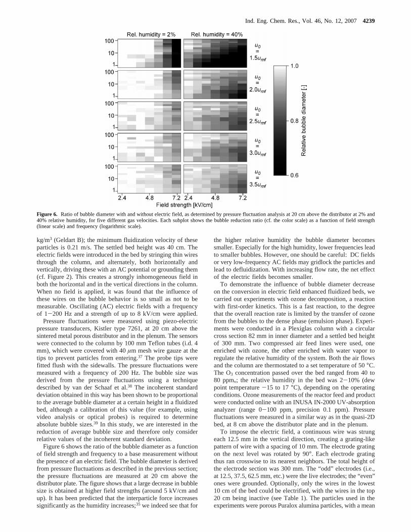
Figure 6 shows the ratio of the bubble diameter as a functionof field strength and frequency to a base measurement withoutthe presence of an electric field. The bubble diameter is derivedfrom pressure fluctuations as described in the previous section;the pressure fluctuations are measured at 20 cm above thedistributor plate. The figure shows that a large decrease in bubblesize is obtained at higher field strengths (around 5 kV/cm andup). It has been predicted that the interparticle force increasessignificantly as the humidity increases;35 we indeed see that for
the higher relative humidity the bubble diameter becomessmaller. Especially for the high humidity, lower frequencies leadto smaller bubbles. However, one should be careful: DC fieldsor very low-frequency AC fields may gridlock the particles andlead to defluidization. With increasing flow rate, the net effectof the electric fields becomes smaller.
To demonstrate the influence of bubble diameter decreaseon the conversion in electric field enhanced fluidized beds, wecarried out experiments with ozone decomposition, a reactionwith first-order kinetics. This is a fast reaction, to the degreethat the overall reaction rate is limited by the transfer of ozonefrom the bubbles to the dense phase (emulsion phase). Experi-ments were conducted in a Plexiglas column with a circularcross section 82 mm in inner diameter and a settled bed heightof 300 mm. Two compressed air feed lines were used, oneenriched with ozone, the other enriched with water vapor toregulate the relative humidity of the system. Both the air flowsand the column are thermostated to a set temperature of 50°C.The O3 concentration passed over the bed ranged from 40 to80 ppmv; the relative humidity in the bed was 2-10% (dewpoint temperature-15 to 17°C), depending on the operatingconditions. Ozone measurements of the reactor feed and productwere conducted online with an INUSA IN-2000 UV-absorptionanalyzer (range 0-100 ppm, precision 0.1 ppm). Pressurefluctuations were measured in a similar way as in the quasi-2Dbed, at 8 cm above the distributor plate and in the plenum.
To impose the electric field, a continuous wire was strungeach 12.5 mm in the vertical direction, creating a grating-likepattern of wire with a spacing of 10 mm. The electrode gratingon the next level was rotated by 90°. Each electrode gratingthus ran crosswise to its nearest neighbors. The total height ofthe electrode section was 300 mm. The “odd” electrodes (i.e.,at 12.5, 37.5, 62.5 mm, etc.) were the live electrodes; the “even”ones were grounded. Optionally, only the wires in the lowest10 cm of the bed could be electrified, with the wires in the top20 cm being inactive (see Table 1). The particles used in theexperiments were porous Puralox alumina particles, with a mean
Figure 6. Ratio of bubble diameter with and without electric field, as determined by pressure fluctuation analysis at 20 cm above the distributor at 2% and40% relative humidity, for five different gas velocities. Each subplot shows the bubble reduction ratio (cf. the color scale) as a function of field strength(linear scale) and frequency (logarithmic scale).
Ind. Eng. Chem. Res., Vol. 46, No. 12, 20074239
(sieved) particle size of 250-300µm and a particle density of900 kg/m3; the minimum fluidization velocity is 3.0 cm/s. Forthe experiment with iron-impregnated particles, 40 g of theparticles were impregnated with 0.5 wt % Fe.
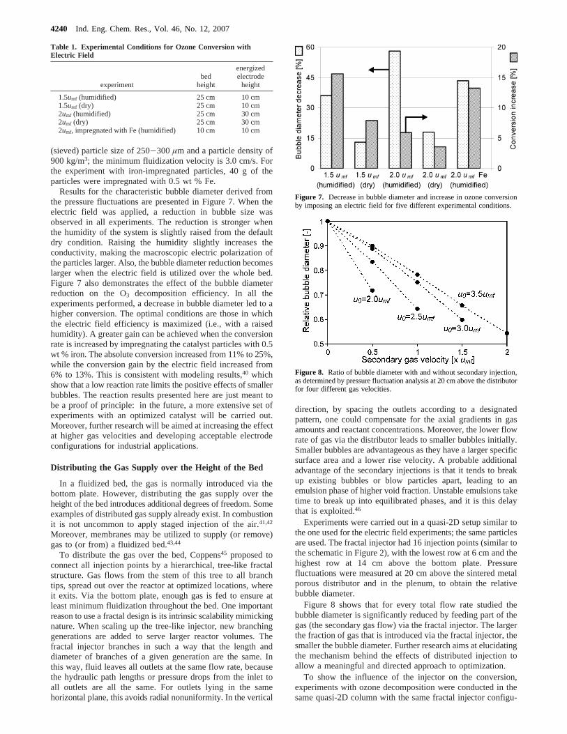
Results for the characteristic bubble diameter derived fromthe pressure fluctuations are presented in Figure 7. When theelectric field was applied, a reduction in bubble size wasobserved in all experiments. The reduction is stronger whenthe humidity of the system is slightly raised from the defaultdry condition. Raising the humidity slightly increases theconductivity, making the macroscopic electric polarization ofthe particles larger. Also, the bubble diameter reduction becomeslarger when the electric field is utilized over the whole bed.Figure 7 also demonstrates the effect of the bubble diameterreduction on the O3 decomposition efficiency. In all theexperiments performed, a decrease in bubble diameter led to ahigher conversion. The optimal conditions are those in whichthe electric field efficiency is maximized (i.e., with a raisedhumidity). A greater gain can be achieved when the conversionrate is increased by impregnating the catalyst particles with 0.5wt % iron. The absolute conversion increased from 11% to 25%,while the conversion gain by the electric field increased from6% to 13%. This is consistent with modeling results,40 whichshow that a low reaction rate limits the positive effects of smallerbubbles. The reaction results presented here are just meant tobe a proof of principle: in the future, a more extensive set ofexperiments with an optimized catalyst will be carried out.Moreover, further research will be aimed at increasing the effectat higher gas velocities and developing acceptable electrodeconfigurations for industrial applications.
Distributing the Gas Supply over the Height of the Bed
In a fluidized bed, the gas is normally introduced via thebottom plate. However, distributing the gas supply over theheight of the bed introduces additional degrees of freedom. Someexamples of distributed gas supply already exist. In combustionit is not uncommon to apply staged injection of the air.41,42
Moreover, membranes may be utilized to supply (or remove)gas to (or from) a fluidized bed.43,44
To distribute the gas over the bed, Coppens45 proposed toconnect all injection points by a hierarchical, tree-like fractalstructure. Gas flows from the stem of this tree to all branchtips, spread out over the reactor at optimized locations, whereit exits. Via the bottom plate, enough gas is fed to ensure atleast minimum fluidization throughout the bed. One importantreason to use a fractal design is its intrinsic scalability mimickingnature. When scaling up the tree-like injector, new branchinggenerations are added to serve larger reactor volumes. Thefractal injector branches in such a way that the length anddiameter of branches of a given generation are the same. Inthis way, fluid leaves all outlets at the same flow rate, becausethe hydraulic path lengths or pressure drops from the inlet toall outlets are all the same. For outlets lying in the samehorizontal plane, this avoids radial nonuniformity. In the vertical
direction, by spacing the outlets according to a designatedpattern, one could compensate for the axial gradients in gasamounts and reactant concentrations. Moreover, the lower flowrate of gas via the distributor leads to smaller bubbles initially.Smaller bubbles are advantageous as they have a larger specificsurface area and a lower rise velocity. A probable additionaladvantage of the secondary injections is that it tends to breakup existing bubbles or blow particles apart, leading to anemulsion phase of higher void fraction. Unstable emulsions taketime to break up into equilibrated phases, and it is this delaythat is exploited.46
Experiments were carried out in a quasi-2D setup similar tothe one used for the electric field experiments; the same particlesare used. The fractal injector had 16 injection points (similar tothe schematic in Figure 2), with the lowest row at 6 cm and thehighest row at 14 cm above the bottom plate. Pressurefluctuations were measured at 20 cm above the sintered metalporous distributor and in the plenum, to obtain the relativebubble diameter.
Figure 8 shows that for every total flow rate studied thebubble diameter is significantly reduced by feeding part of thegas (the secondary gas flow) via the fractal injector. The largerthe fraction of gas that is introduced via the fractal injector, thesmaller the bubble diameter. Further research aims at elucidatingthe mechanism behind the effects of distributed injection toallow a meaningful and directed approach to optimization.
To show the influence of the injector on the conversion,experiments with ozone decomposition were conducted in thesame quasi-2D column with the same fractal injector configu-
Table 1. Experimental Conditions for Ozone Conversion withElectric Field
experimentbed
height
energizedelectrode
height
1.5umf (humidified) 25 cm 10 cm1.5umf (dry) 25 cm 10 cm2umf (humidified) 25 cm 30 cm2umf (dry) 25 cm 30 cm2umf, impregnated with Fe (humidified) 10 cm 10 cm
Figure 7. Decrease in bubble diameter and increase in ozone conversionby imposing an electric field for five different experimental conditions.
Figure 8. Ratio of bubble diameter with and without secondary injection,as determined by pressure fluctuation analysis at 20 cm above the distributorfor four different gas velocities.
4240 Ind. Eng. Chem. Res., Vol. 46, No. 12, 2007
ration. The bed mass consisted of 40 g of 1 wt % ironimpregnated porous Puralox alumina particles diluted with 855g of the same non-impregnated particles to give a settled bedheight of 40 cm. The particle size was 250-300 µm, and theparticle density was approximately 900 kg/m3; the minimumfluidization velocity is 3.0 cm/s. The temperature of the feedgas and the cabinet in which the column was located were heatedto 55°C. The relative humidity stayed within the range of 1-2%over the course of these experiments. The ozone concentrationin the feed was in the range of 60-70 ppmv. The ozoneconcentrations in the feed and outlet were analyzed with anINUSA 2000 O3 analyzer. Pressure fluctuations were measuredjust above the distributor plate and at 19 cm height to obtainthe relative bubble diameter.
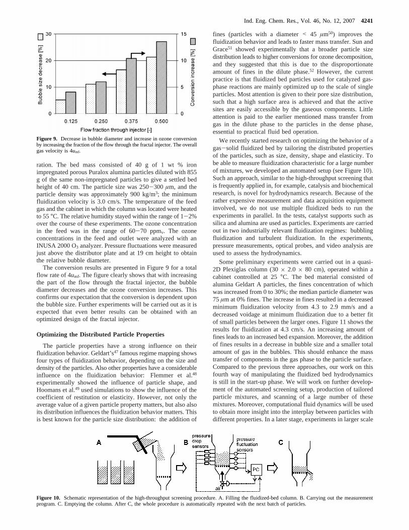
The conversion results are presented in Figure 9 for a totalflow rate of 4umf. The figure clearly shows that with increasingthe part of the flow through the fractal injector, the bubblediameter decreases and the ozone conversion increases. Thisconfirms our expectation that the conversion is dependent uponthe bubble size. Further experiments will be carried out as it isexpected that even better results can be obtained with anoptimized design of the fractal injector.
Optimizing the Distributed Particle Properties
The particle properties have a strong influence on theirfluidization behavior. Geldart’s47 famous regime mapping showsfour types of fluidization behavior, depending on the size anddensity of the particles. Also other properties have a considerableinfluence on the fluidization behavior: Flemmer et al.48
experimentally showed the influence of particle shape, andHoomans et al.49 used simulations to show the influence of thecoefficient of restitution or elasticity. However, not only theaverage value of a given particle property matters, but also alsoits distribution influences the fluidization behavior matters. Thisis best known for the particle size distribution: the addition of
fines (particles with a diameter< 45 µm50) improves thefluidization behavior and leads to faster mass transfer. Sun andGrace51 showed experimentally that a broader particle sizedistribution leads to higher conversions for ozone decomposition,and they suggested that this is due to the disproportionateamount of fines in the dilute phase.52 However, the currentpractice is that fluidized bed particles used for catalyzed gas-phase reactions are mainly optimized up to the scale of singleparticles. Most attention is given to their pore size distribution,such that a high surface area is achieved and that the activesites are easily accessible by the gaseous components. Littleattention is paid to the earlier mentioned mass transfer fromgas in the dilute phase to the particles in the dense phase,essential to practical fluid bed operation.
We recently started research on optimizing the behavior of agas-solid fluidized bed by tailoring the distributed propertiesof the particles, such as size, density, shape and elasticity. Tobe able to measure fluidization characteristic for a large numberof mixtures, we developed an automated setup (see Figure 10).Such an approach, similar to the high-throughput screening thatis frequently applied in, for example, catalysis and biochemicalresearch, is novel for hydrodynamics research. Because of therather expensive measurement and data acquisition equipmentinvolved, we do not use multiple fluidized beds to run theexperiments in parallel. In the tests, catalyst supports such assilica and alumina are used as particles. Experiments are carriedout in two industrially relevant fluidization regimes: bubblingfluidization and turbulent fluidization. In the experiments,pressure measurements, optical probes, and video analysis areused to assess the hydrodynamics.
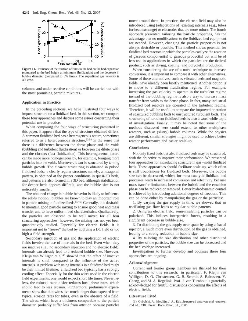
Some preliminary experiments were carried out in a quasi-2D Plexiglas column (30× 2.0 × 80 cm), operated within acabinet controlled at 25°C. The bed material consisted ofalumina Geldart A particles, the fines concentration of whichwas increased from 0 to 30%; the median particle diameter was75µm at 0% fines. The increase in fines resulted in a decreasedminimum fluidization velocity from 4.3 to 2.9 mm/s and adecreased voidage at minimum fluidization due to a better fitof small particles between the larger ones. Figure 11 shows theresults for fluidization at 4.3 cm/s. An increasing amount offines leads to an increased bed expansion. Moreover, the additionof fines results in a decrease in bubble size and a smaller totalamount of gas in the bubbles. This should enhance the masstransfer of components in the gas phase to the particle surface.Compared to the previous three approaches, our work on thisfourth way of manipulating the fluidized bed hydrodynamicsis still in the start-up phase. We will work on further develop-ment of the automated screening setup, production of tailoredparticle mixtures, and scanning of a large number of thesemixtures. Moreover, computational fluid dynamics will be usedto obtain more insight into the interplay between particles withdifferent properties. In a later stage, experiments in larger scale
Figure 9. Decrease in bubble diameter and increase in ozone conversionby increasing the fraction of the flow through the fractal injector. The overallgas velocity is 4umf.
Figure 10. Schematic representation of the high-throughput screening procedure. A. Filling the fluidized-bed column. B. Carrying out the measurementprogram. C. Emptying the column. After C, the whole procedure is automatically repeated with the next batch of particles.
Ind. Eng. Chem. Res., Vol. 46, No. 12, 20074241
columns and under reactive conditions will be carried out withthe most promising particle mixtures.
Application in Practice
In the preceding sections, we have illustrated four ways toimpose structure on a fluidized bed. In this section, we comparethese four approaches and discuss some issues concerning theirpotential use in practice.
When comparing the four ways of structuring presented inthis paper, it appears that the type of structure obtained differs.A common fluidized bed has a heterogeneous nature, sometimesreferred to as a heterogeneous structure,53,54 in the sense thatthere is a difference between the dense phase and the voids(bubbling and turbulent fluidization) or between the dilute phaseand the clusters (fast fluidization). This heterogeneous naturecan be made more homogeneous by, for example, bringing moreparticles into the voids. Moreover, it can be structured by tamingbubble growth. The clearest structuring is obtained in pulsedfluidized beds: a clearly regular structure, namely, a hexagonalpattern, is obtained at the proper conditions in quasi-2D beds,and patterns are also formed in a 3D bed, although stabilizationfor deeper beds appears difficult, and the bubble size is notnoticeably smaller.
The obtained change in bubble behavior is likely to influencethe solids motion: bubbles are known to play an important rolein particle mixing in fluidized beds.55-57 Generally, it is desirableto maintain good particle mixing to ensure good heat and masstransfer and to have uniform bed characteristics. Qualitatively,the particles are observed to be well mixed for all fourstructuring approaches; however, the mixing has not yet beenquantitatively studied. Especially for electric fields, it isimportant not to “freeze” the bed by applying a DC field or toohigh a field strength.
Secondary injection of gas and the application of electricfields involve the use of internals in the bed. Even when theyare inactive (i.e., no secondary injection and no electric field),internals can already lead to a reduced bubble size. However,Kleijn van Willigen et al.46 showed that the effect of inactiveinternals is small compared to the influence of the activeinternals. A problem with using internals in a fluidized bed mightbe their limited lifetime: a fluidized bed typically has a stronglyeroding effect. Especially for the thin wires used in the electricfield experiments, one would expect short life times. Neverthe-less, the reduced bubble size reduces local shear rates, whichshould lead to less erosion. Furthermore, preliminary experi-ments show that thin wires live much longer than expected fromtypical erosion rates for tubes, even in the absence of a field.The wires, which have a thickness comparable to the particlediameter, probably suffer less from attrition because particles
move around them. In practice, the electric field may also beintroduced using (adaptations of) existing internals (e.g., tubesfor heat exchange) or electrodes that are more robust. The fourthapproach presented, tailoring the particle properties, has theadvantage that no modifications to the fluidized bed equipmentare needed. However, changing the particle properties is notalways desirable or possible. This method shows potential forfluidized bed reactors in which the particles catalyze the reactionof gaseous component(s) to gaseous product(s) but will be ofless use in applications in which the particles are the desiredproduct, such as drying, coating, and polyolefin production.
When considering the use of a novel technique to increaseconversion, it is important to compare it with other alternatives.Some of these alternatives, such as vibrated beds and magneticfields, have already been briefly mentioned. Another option isto move to a different fluidization regime. For example,increasing the gas velocity to operate in the turbulent regimeinstead of the bubbling regime is also a way to increase masstransfer from voids to the dense phase. In fact, many industrialfluidized bed reactors are operated in the turbulent regime.Therefore, it will be useful to compare the improved operationof structured bubbling beds to unstructured turbulent beds. Thestructuring of turbulent fluidized beds is also a worthwhile topicof investigation. Finally, it may be noted that some of themethods discussed here could extend to other multiphasereactors, such as (slurry) bubble columns. While the physicsare different, similar strategies might be used to achieve betterreactor performance and easier scale-up.
Conclusions
Not only fixed beds but also fluidized beds may be structured,with the objective to improve their performance. We presentedfour approaches for introducing structure in gas-solid fluidizedbeds. These approaches should facilitate scale-up, which oftenis still troublesome for fluidized beds. Moreover, the bubblesize can be decreased, which, for most catalytic fluidized bedprocesses, leads to increased conversion and selectivity, becausemass transfer limitations between the bubble and the emulsionphase can be reduced or removed. Better hydrodynamic controlis achieved by introducing additional degrees of freedom. Thiscan be done either by manipulating the gas or the particles:
1. By varying the gas supply in time, we showed that anoscillating gas flow leads to regular bubble patterns.
2. Using an electric field, semi-insulating particles can bepolarized. This induces interparticle forces, resulting in asignificant decrease in bubble size.
3. To distributing the gas supply over space by using a fractalinjector, a much more even distribution of the gas is obtained,leading to a strong reduction in bubble size.
4. By tailoring the size distribution and other distributedproperties of the particles, the bubble size can be decreased andthe bed voidage increased.
Investigations to further develop and optimize these fourapproaches are ongoing.
AcknowledgmentCurrent and former group members are thanked for their
contributions to this research: in particular, F. Kleijn vanWilligen, D. O. Christensen, G. B. Schmit, S. Baltussen, Y.Cheng, and M. A. Regelink. Prof. J. van Turnhout is gratefullyacknowledged for fruitful discussions concerning the effects ofelectric fields.
Literature Cited(1) Cybulski, A., Moulijn, J. A., Eds.Structured catalysts and reactors,
2nd ed.; CRC Press: Boca Raton, FL, 2005.
Figure 11. Influence of the fraction of fines in the bed on the bed expansion(compared to the bed height at minimum fluidization) and the decrease inbubble diameter (compared to 0% fines). The superficial gas velocity is4.3 cm/s.
4242 Ind. Eng. Chem. Res., Vol. 46, No. 12, 2007
(2) Michiel, T.; Kreutzer, M. T.; Kapteijn, F.; Moulijn, J. A. Shouldn’tcatalysts shape up?: Structured reactors in general and gas-liquid monolithreactors in particular.Catal. Today2006, 111, 111-118.
(3) Broadbelt, L. J.; Snurr, R. Q. Applications of molecular modelingin heterogeneous catalysis research.Appl. Catal., A2000, 200, 23-46.
(4) Senkan, S. Combinatorial Heterogeneous Catalysis - A New Pathin an Old Field.Angew. Chem., Int. Ed.2001, 40, 312-329.
(5) Ying, J. Y.; Mehnert, C. P.; Wong, M. S. Synthesis and applicationsof supramolecular-templated mesoporous materials.Angew. Chem., Int. Ed.1999, 38, 56-77.
(6) Cybulski, A.; Moulijn, J. A. Modeling of heat-transfer in metallicmonoliths consisting of sinusoidal cells.Chem. Eng. Sci.1994, 49, 19-27.
(7) Smits, H. A.; Stankiewicz, A.; Glasz, W. C.; Fogl, T. H. A.; Moulijn,J. A. Selective three-phase hydrogenation of unsaturated hydrocarbons ina monolithic reactor.Chem. Eng. Sci.1996, 51, 3019-3025.
(8) Lebens, P. J. M.; vanderMeijden, R.; Edvinsson, R. K.; Kapteijn,F.; Sie, S. T.; Moulijn, J. A. Hydrodynamics of gas-liquid countercurrentflow in internally finned monolithic structures.Chem. Eng. Sci.1997, 52,3893-3899.
(9) Cybulski, A.; Stankiewicz, A.; Albers, R. K. E.; Moulijn, J. A.Monolithic reactors for fine chemicals industries: A comparative analysisof a monolithic reactor and a mechanically agitated slurry reactor.Chem.Eng. Sci.1999, 54, 2351-2358.
(10) Heiszwolf, J. J.; Engelvaart, L. B.; van den Eijnden, M. G.; Kreutzer,M. T.; Kapteijn, F.; Moulijn, J. A. Hydrodynamic aspects of the monolithloop reactor.Chem. Eng. Sci.2001, 56, 805-812.
(11) Nijhuis, T. A.; Beers, A. E. W.; Vergunst, T.; Hoek, I.; Kapteijn,F.; Moulijn, J. A. Preparation of monolithic catalysts.Cat. ReV.-Sci. Eng.2001, 43, 345-380.
(12) Nijhuis, T. A.; Dautzenberg, F. M.; Moulijn, J. A. Modeling ofmonolithic and trickle-bed reactors for the hydrogenation of styrene.Chem.Eng. Sci.2003, 58, 1113-1124.
(13) Kreutzer, M. T.; Bakker, J. J. W.; Kapteijn, F.; Moulijn, J. A.;Verheijen, P. J. T. Scaling-up multiphase monolith reactors: Linkingresidence time distribution and feed maldistribution.Ind. Eng. Chem. Res.2005, 44, 4898-4913.
(14) Knowlton, T. M.; Karri, S. B. R.; Issangya, A. Scale-up of fluidized-bed hydrodynamics.Powder Technol.2005, 150, 72-77.
(15) Sanderson, J.; Rhodes, M. Bubbling fluidized bed scaling laws:Evaluation at large scales.AIChE J.2005, 51, 2686-2694.
(16) van Ommen, J. R.; Teuling, M.; Nijenhuis, J.; van Wachem, B. G.M. Computational validation of the scaling rules for fluidized beds.PowderTechnol.2006, 163, 32-40.
(17) Chavarie, C.; Grace, J. R. Interphase mass transfer in a gas fluidizedbed.Chem. Eng. Sci.1976, 31, 41-749.
(18) Kai, T.; Tsutsui, T.; Furusaki, S. Features of fluidized catalyst bedsfor proper design and operation of catalytic reactions.Ind. Eng. Chem. Res.2004, 43, 5474-5482.
(19) Kunii, D.; Levenspiel, O.Fluidization Engineering, 2nd ed.;Butterworth-Heinemann: Boston,1991.
(20) Kaart, S.; Schouten, J. C.; van den Bleek, C. M. Improvingconversion and selectivity of catalytic reactions in bubbling gas-solidfluidized bed reactors by control of the nonlinear bubble dynamics.Catal.Today1999, 48, 185-194.
(21) de Korte, R. J.; Schouten, J. C.; van den Bleek, C. M. Controllingbubble coalescence in a fluidized-bed model using bubble injection.AIChEJ. 2001, 47, 851-860.
(22) Harrison, A. J. L.; Lim, C. N.; Gilbertson, M. A. Modelling andcontrol of the dynamics of bubbling fluidized beds.Proc. Inst. Mech. Eng.,Part E: J. Process Mechanical Engineering2006, 220, 43-53.
(23) Massimilla, L.; Volpicelli, G.; Raso, G. A study on pulsating gasfluidization of beds of particles.Chem. Eng. Prog., Symp. Ser.1966, 62,63-70.
(24) Wong, H. W.; Baird, M. H. I. Fluidization in a pulsed gas flow.Chem. Eng. J.1971, 2, 104-113.
(25) Koksal, M.; Vural, H. Bubble size control in a two-dimensionalfluidized bed using a moving double plate distributor.Powder Technol.1998, 95, 205-213.
(26) Pence, D. V.; Beasley, D. E. Chaos suppression in gas-solidfluidization. Chaos1998, 8, 514-519.
(27) Coppens, M.-O.; Regelink, M. A.; van den Bleek, C. M. Pulsationinduced transition from chaos to periodically ordered patterns in fluidisedbeds. Proceedings of the 4th World Congress on Particle Technology (CD-ROM); Sydney, Australia, July 21-25, 2002; Paper 355.
(28) Wang, X. S.; Rhodes, M. J. Pulsed fluidization - a DEM study ofa fascinating phenomenon.Powder Technol.2005, 159, 142-149.
(29) Melo, F.; Umbanhowar, P.; Swinney, H. L. Transition to parametricwave patterns in a vertically oscillated granular layer.Phys. ReV. Lett.1994,72, 172-175.
(30) Rietema, K.; Piepers, H. W. The effect of interparticle forces onthe stability of gas-fluidized bedssI. Experimental evidence.Chem. Eng.Sci., 1990, 45, 1627-1639.
(31) Seville, J. P. K.; Willett, C. D.; Knight, P. C. Inter-particle forcesin fluidisation: a review.Powder Technol.2000, 113, 261-268.
(32) Pandit, Jai Kant; Wang, X. S.; Rhodes, M. J. On Geldart Group Abehaviour in fluidized beds with and without cohesive interparticle forces:A DEM study.Powder Technol.2006, 164, 130-138.
(33) Rosensweig, R. E. Process concepts using field-stabilized two-phaseflow. J. Electrost.1995, 34, 163-187.
(34) Hristov, J. Magnetic field assisted fluidization- A unified approach- Part 1. Fundamentals and relevant hydrodynamics of gas-fluidized beds(batch solids mode).ReV. Chem. Eng.2002, 18, 295-509.
(35) Kleijn van Willigen, F.; van Ommen, J. R.; van Turnhout, J.; vanden Bleek, C. M. Bubble size reduction in electric-field-enhanced fluidizedbeds.J. Electrostat.2005, 63, 943-948.
(36) Colver, G. M. An interparticle force model for ac-dc electric fieldsin powders.Powder Technol.2000, 112, 126-136.
(37) van Ommen, J. R.; Schouten, J. C.; vander Stappen, M. L. M.; vanden Bleek, C. M. Response Characteristics of Probe-Transducer Systemsfor Pressure Measurements in Gas-Solid Fluidized Beds: How to PreventPitfalls in Dynamic Pressure Measurements.Powder Technol.1999, 106,199-218. Erratum:Powder Technol. 2000, 113, 217.
(38) van der Schaaf, J.; Schouten, J. C.; Johnson, F.; van den Bleek, C.M. Non-intrusive determination of bubble and slug length scales in fluidizedbeds by decomposition of the power spectral density of pressure time series.Int. J. Multiphase Flow2002, 28, 865-880.
(39) Kleijn van Willigen, F.; van Ommen, J. R.; van Turnhout, J.; vanden Bleek, C. M. Bubble size reduction in a fluidized bed by electric fields.Int. J. Chem. React. Eng.2003, 1, paper A21 (http://www.bepress.com/ijcre/vol1/A21).
(40) Kleijn van Willigen, F.; van Ommen, J. R.; van Turnhout, J.; vanden Bleek, C. M. Conversion Increase in Electric Field Enhanced FluidizedBeds.2006, in preparation.
(41) Jensen, A.; Johnsson, J. E.; Andries, J.; Laughlin, K.; Read, G.;Mayer, M.; Baumann, H.; Bonn, B. Formation and reduction of NOx inpressurized fluidized-bed combustion of coal.Fuel 1995, 74, 1555-1569.
(42) Lyngfelt, A.; Amand, L. E.; Gustavsson, L.; Leckner, B. Methodsfor reducing the emission of nitrous oxide from fluidized bed combustion.Energy ConVers. Manage.1996, 37, 1297-1302.
(43) Adris, A. E. M.; Grace, J. R. Characteristics of fluidized-bedmembrane reactors: Scale-up and practical issues.Ind. Eng. Chem. Res.1997, 36, 4549-4556.
(44) Patil, C. S.; van Sint Annaland, M.; Kuipers, J. A. M. Experimentalstudy of a membrane assisted fluidized bed reactor for H2 production bysteam reforming of CH4.Chem. Eng. Res. Des.2006, 84, 399-404.
(45) Coppens, M.-O. Structuring fluidized bed operation in a natureinspired way. InFluidization XI; Arena, U., Chirone, R., Miccio, M.,Salatino, P., Eds.; Engineering Conferences International: New York, 2004;pp 83-90.
(46) Kleijn van Willigen, F.; Christensen, D.; van Ommen, J. R.;Coppens, M.-O. Imposing dynamic structures on fluidised beds.Catal.Today2005, 105, 560-568.
(47) Geldart, D. Types of gas fluidization.Powder Technol.1973, 7,285-292.
(48) Flemmer, R. L. C.; Pickett, J.; Clark, N. N. An experimental studyon the effect of particle shape on fluidization behavior.Powder Technol.1993, 77, 123-133.
(49) Hoomans, B. P. B.; Kuipers, J. A. M.; van Swaaij, W. P. M.Granular dynamics simulation of segregation phenomena in bubbling gas-fluidized beds.Powder Technol.2000, 109, 41-48.
(50) Yates, J. G.; Newton, D. Fine particle effects in a fluidized-bedreactor.Chem. Eng. Sci.1986, 41, 801-806.
(51) Sun, G.; Grace, J. R. The effect of particle size distribution on theperformance of a catalytic fluidized bed reactor.Chem. Eng. Sci.1990, 45,2187-2194.
(52) Sun, G.; Grace, J. R. Experimental determination of particledispersion in voids in a fluidized bed.Powder Technol.1994, 80, 29-34.
(53) Yerushalmi, J.; Cankurt, N. T. Further studies of the regimes offluidization. Powder Technol.1979, 24, 187-205.
Ind. Eng. Chem. Res., Vol. 46, No. 12, 20074243

(54) Jinghai, L.; Cheng, C.; Zhang, Z.; Yuan, J.; Nemet, A.; Fett, F. N.The EMMS model - its application, development and updated concepts.Chem. Eng. Sci.1999, 54, 5409-5425.
(55) Rowe, P.; Partridge, B.; Cheney, A.; Henwood, G.; Lyall, E. Themechanics of solids mixing in fluidised beds.Trans. Inst. Chem. Eng.1965,43, 271-286.
(56) Hoffmann, A. C.; Janssen, L. P. B. M.; Prins, J. Particle segregationin fluidized binary mixtures.Chem. Eng. Sci.1993, 48, 1583-1592.
(57) Eames, I.; Gilbertson, M. A. Mixing and drift in gas-fluidised beds.Powder Technol.2005, 154, 195-203.
ReceiVed for reView October 14, 2006ReVised manuscript receiVed February 10, 2007
AcceptedFebruary 13, 2007
IE061318O
4244 Ind. Eng. Chem. Res., Vol. 46, No. 12, 2007