Embed Size (px)
Citation preview

1
TRACER TONE
VISUAL CONT.TALK
OFF / POLARITY
AUDIBLE CONT.WARBLE
PULSE
CORDLESSINTERFACE
OVERLOAD PROTECTED
UNLOCK BATTERY TEST
AC / RING
TRIPLETT
REV NORM
G RJ-45 Jack
H Battery Test / Cadence LED
I Warble / Pulse Button
A Cordless Interface
B Continuity / Talk LED
C Unlock Button
D Function Switch
E Polarity LEDs
D
A
C
B
E
F
F RJ-45 to RJ-11 Adaptor
G
H
I
J Alligator Clips
J
84-8547/03
Test Equipment Depot - 800.517.8431 99 Washington Street Melrose, MA 02176
TestEquipmentDepot.com

2
Introduction:The FOX 2 is the next generation version of Triplett’spopular FOX Tone Generator. The FOX 2 incorporatesnumerous improvements, born from years of experi-ence with the original FOX design, and from workingwith our customers to provide cable tracing solutions.Many new features like TrueTrace and 120VAC LineCross protection are time saving and convenient forthe user. In addition, unique features of the originalFOX design, like the Line Powered Tone Generationmode, are retained. The FOX 2 sets a new standardfor cable tracing technology.Features:• “TrueTrace” - Cadence of tracer tone changes when pair is momentarily shorted, allowing for definite ID of target wire pair• Cordless Phone Interface - use a standard cordless phone for hands-free TrueTrace”!• 3 Methods of Connectivity • RJ-11 plug for tracing Telephone lines • RJ-45 Jack for tracing LAN cables (trace BNC cables w/ optional RJ-45 to BNC adaptor) • Alligator clips for connection to stripped wires or terminal panels
3
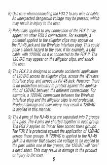
• “Trip-Latch” a unique latch testing technique using “TrueTrace” for testing Alarm Sensors• Overload Protected - 120VAC Line Cross Protection• Overload Warning Beeper - alerts user to potential hazards• Warble/Pulse Tracer Tone - Selectable tone for audible & visual ID using Hound or Hound 2 Probe Inductive Tracer• High Output Tracer Tone• Generates 2 of 6 user selectable Tracer Tones• Internal User Selectable Settings - HI/LO Pitch Shift, Warble/Continuous Tracer Tone, On/Off Audio Pilot Tone, On/Off Cadence Shift• Tone/Battery LED - indicates that Tracer Tone is on and battery is OK• Audio Pilot Tone - confirms the Tracer Toner signal• Visual & Audible Continuity Test• Red/Green Telephone Line Polarity LEDs - also indicates AC/RING Signal• Supplies “Talk Power” to allow communicating between handsets (talksets) or powering a telephone• Line powered in Tone Mode• Built in Telephone Ringer• “Power Latch” - prevents accidental turn-ons• Magnetic Back - stick the Fox 2 to steel surfaces• Works with either Hound or Hound 2 Probe Inductive Tracer• Powered by standard 9 Volt Battery (not included)

4
Safety Warnings and Cautions:The FOX 2 is designed to tolerate momentary unintentionalapplication of 120VAC to all of its external connections. Awarning beeper sounds when 120VAC is accidentally applied.The FOX 2 is not designed to be used as a 120VAC detec-tor. Although the FOX 2 will tolerate 120VAC without dam-age, a shock hazard is present. The user may be injuredby electrical shock. The circuitry in the FOX 2 is designedto reduce the possibility of damage to the product, not toguarantee that the user will not be injured.
1) Do not use the FOX 2 as a 120VAC voltage detector.2) The 120VAC warning beeper will not sound if the battery is dead. Do not rely on the beeper to indicate the presence of dangerous voltages.3) The 120VAC protection circuit in the FOX 2 uses a light bulb, whose glow can sometimes, but not always, be seen thru the FOX 2’s case. Do not rely on this visual indication to determine the presence of dangerous voltages.
4) The FOX 2 is not designed to tolerate accidental applica- tion of voltages exceeding 132VAC 60Hz. Applying higher voltages may cause damage to the FOX 2, and may injure the user.5) The FOX 2 is not designed to indicate any degree of preci- sion in the accidentally applied voltage. That is, when the warning beeper sounds, this does not mean that exactly 120VAC is present. The warning beeper will sound for voltage from approximately 80VAC to 132VAC.
5
6) Use care when connecting the FOX 2 to any wire or cable. An unexpected dangerous voltage may be present, which may result in injury to the user.7) Potentials applied to any connection of the FOX 2 may appear on other FOX 2 connections. For example, a potential applied to the alligator clips may appear on the RJ-45 jack and the Wireless Interface plug. This could pose a shock hazard to the user, if for example, a LAN cable with 120VAC on it is connected to the FOX 2. The 120VAC may appear on the alligator clips, and shock the user.8) The FOX 2 is designed to tolerate accidental application of 120VAC across its alligator clips, across the Wireless Interface plug, and across its RJ-45 jack. However, there is no protection circuitry to protect against the applica- tion of 120VAC between the different connections. For example, a 120VAC connection between the Wireless Interface plug and the alligator clips is not protected. Product damage and user injury may result if 120VAC is applied in this manner.
9) The 8 pins of the RJ-45 jack are separated into 2 groups of 4 pins. The 4 pins are shorted together in each group. The FOX 2 applies its Tracer Tone across these groups. The FOX 2 is protected against the application of 120VAC across these groups. If 120VAC is applied to the RJ-45 jack in a manner that causes the voltage to be applied to the pins within one of the groups, the 120VAC will “see” a dead short. This may result in damage to the product or injury to the user.

10) Use caution when working with telephone lines. They can support dangerous voltages. 50VDC is often present, and 100VAC may be present during ringing. Additionally, telephone lines may support dangerous levels of common mode voltages. In some circumstances, user injury may result.11) Use caution when working with any long unconnected wire or cable. Under some conditions, unconnected wires may “float up” to dangerous potentials, and touching them may result in user injury.
Specifications:Telephone Line Polarity Test: Indication: Green or Red LED lights for Normal or
Reversed polarity Load: Approx. 13mA at 50VDC (usually less than
off-hook recognition current) Protection: Tolerates momentary 120VAC Line Cross
without damage.
Telephone Line Ringer and Visual Ring Indication: Indication: Red and Green LEDs light simultaneously,
Beeper sounds Protection: Tolerates momentary 120VAC Line Cross
without damage.
Test Equipment Depot - 800.517.8431 99 Washington Street Melrose, MA 02176
TestEquipmentDepot.com
7
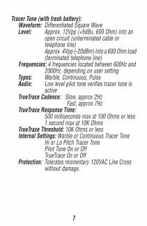
Tracer Tone (with fresh battery): Waveform: Differentiated Square Wave Level: Approx. 12Vpp (+5dBu, 600 Ohm) into an
open circuit (unterminated cable ortelephone line)Approx. 4Vpp (-20dBm) into a 600 Ohm load(terminated telephone line)
Frequencies: 4 frequencies located between 600Hz and2000Hz, depending on user setting
Types: Warble, Continuous, Pulse Audio: Low level pilot tone verifies tracer tone is
active TrueTrace Cadence: Slow, approx 2Hz
Fast, approx 7Hz TrueTrace Response Time:
500 milliseconds max at 100 Ohms or less1 second max at 10K Ohms
TrueTrace Threshold: 10K Ohms or less Internal Settings: Warble or Continuous Tracer Tone
Hi or Lo Pitch Tracer TonePilot Tone On or OffTrueTrace On or Off
Protection: Tolerates momentary 120VAC Line Crosswithout damage.
8
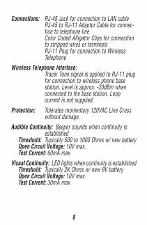
Connections: RJ-45 Jack for connection to LAN cableRJ-45 to RJ-11 Adaptor Cable for connec-tion to telephone lineColor Coded Alligator Clips for connectionto stripped wires or terminalsRJ-11 Plug for connection to WirelessTelephone
Wireless Telephone Interface:Tracer Tone signal is applied to RJ-11 plugfor connection to wireless phone basestation. Level is approx. -20dBm whenconnected to the base station. Loopcurrent is not supplied.
Protection: Tolerates momentary 120VAC Line Crosswithout damage.
Audible Continuity: Beeper sounds when continuity isestablished
Threshold: Typically 500 to 1000 Ohms w/ new battery Open Circuit Voltage: 10V max. Test Current: 60mA maxVisual Continuity: LED lights when continuity is established Threshold: Typically 2K Ohms w/ new 9V battery Open Circuit Voltage: 10V max. Test Current: 30mA max
9
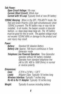
Talk Power: Open Circuit Voltage: 10v max. Current (Short Circuit): 30mA max Current with 1K Loop: Typically 5mA w/ new 9V battery120VAC Warning: When in the OFF / POLARITY mode, the Red and Green Polarity LEDs light simultaneously when 120VAC is present. The 9V battery may or may not be installed. In all modes, the beeper sounds in staccato fashion, i.e. beep-beep-beep-beep etc. The 9V battery must be good for this to work. The applied voltage must not exceed 132VAC 60Hz or damage to the product and user injury may result.Power: Battery: Standard 9V Alkaline Battery Battery Life: Approx. 100 hours continuous in Tone
Generator mode Telephone Line Powered Operation: Tone Generator
operates without 9V battery installed.Operates from standard telephone line(46 to 53V, 400 to 1800 Ohms) in normalor reverse polarity.
Dimensions: Case: 3.75"H x 2.5"W x 1.25"T Leads: Alligator Clips: Typically 10 inches long Wireless Interface: Typically 7 inches long RJ-45 to RJ-11 Adaptor: Typically 10 inches longWeight: Typically 6 ounces including battery
10
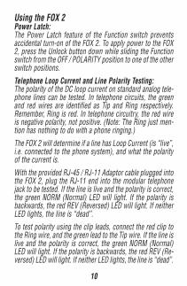
Using the FOX 2Power Latch:The Power Latch feature of the Function switch preventsaccidental turn-on of the FOX 2. To apply power to the FOX2, press the Unlock button down while sliding the Functionswitch from the OFF / POLARITY position to one of the otherswitch positions.Telephone Loop Current and Line Polarity Testing:The polarity of the DC loop current on standard analog tele-phone lines can be tested. In telephone circuits, the greenand red wires are identified as Tip and Ring respectively.Remember, Ring is red. In telephone circuitry, the red wireis negative polarity, not positive. (Note: The Ring just men-tion has nothing to do with a phone ringing.)The FOX 2 will determine if a line has Loop Current (is “live”,i.e. connected to the phone system), and what the polarityof the current is.
With the provided RJ-45 / RJ-11 Adaptor cable plugged intothe FOX 2, plug the RJ-11 end into the modular telephonejack to be tested. If the line is live and the polarity is correct,the green NORM (Normal) LED will light. If the polarity isbackwards, the red REV (Reversed) LED will light. If neitherLED lights, the line is “dead”.To test polarity using the clip leads, connect the red clip tothe Ring wire, and the green lead to the Tip wire. If the line islive and the polarity is correct, the green NORM (Normal)LED will light. If the polarity is backwards, the red REV (Re-versed) LED will light. If neither LED lights, the line is “dead”.
11
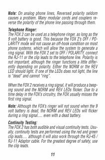
Note: On analog phone lines, Reversed polarity seldomcauses a problem. Many modular cords and couplers re-verse the polarity of the phone line passing through them.Telephone Ringer:The FOX 2 can be used as a telephone ringer, as long as the9 volt battery is good. This because the FOX 2’s OFF / PO-LARITY mode will not cause an off-hook condition on mostphone systems, which will allow the system to generate aring signal. With the FOX 2 set to OFF / POLARITY, connectthe RJ-11 or the clip leads to the telephone line. Polarity isnot important, although the ringer functions a little differ-ently depending on polarity. Either the NORM or the REVLED should light. If one of the LEDs does not light, the lineis “dead” and cannot “ring”.
When the FOX 2 receives a ring signal, it will produce a beep-ing sound and the NORM and REV LEDs flicker. Due to atime delay in the FOX’s circuitry, the FOX usually misses thefirst ring signal.Note: Although the FOX’s ringer will not sound when the 9volt battery is dead, the NORM and REV LEDs will flickerduring a ring signal..... even with a dead battery.Continuity Testing:The FOX 2 has both audible and visual continuity tests. Usu-ally, continuity tests are performed using the red and greenclip leads..... although it will also work through the RJ-45 /RJ-11 Adaptor cable. For the greatest degree of safety, usethe clip leads.

To test for continuity, select the desired mode (either AU-DIBLE CONT or VISUAL CONT / TALK) and then connect theclip leads to the circuit to be tested. If there is continuity,either the beeper will sound or the VISUAL CONT / TALKLED will light.
Helpful Hints:The FOX 2’s 120VAC protection circuitry may prevent thecontinuity beeper or LED from sounding or lighting if theclip leads are connected to the circuit to be tested before theFOX 2’s switch is set to the AUDIBLE CONT or VISUAL CONT/ TALK position. To use the FOX 2’s continuity testing fea-tures, set the switch on the FOX 2 to the AUDIBLE CONT orVISUAL CONT / TALK position before connecting the FOX 2to the circuit to be tested.If the circuit being tested has AC or DC voltage present, theFOX 2 may not identify continuity correctly.Battery Test:A continuous battery test is performed while in the FOX 2 isin the TRACER TONE mode. If the battery is good, the BAT-TERY TEST LED will flash. If the battery is weak, the LED willnot flash.Helpful Hints:The FOX 2 will often work in the TRACER TONE mode longafter the LED has stopped flashing. However, for the stron-gest tracer signal, the battery should be replaced soon afterthe LED stops flashing.
Test Equipment Depot - 800.517.8431 99 Washington Street Melrose, MA 02176
TestEquipmentDepot.com
13
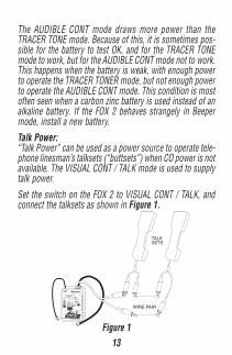
The AUDIBLE CONT mode draws more power than theTRACER TONE mode. Because of this, it is sometimes pos-sible for the battery to test OK, and for the TRACER TONEmode to work, but for the AUDIBLE CONT mode not to work.This happens when the battery is weak, with enough powerto operate the TRACER TONER mode, but not enough powerto operate the AUDIBLE CONT mode. This condition is mostoften seen when a carbon zinc battery is used instead of analkaline battery. If the FOX 2 behaves strangely in Beepermode, install a new battery.Talk Power:“Talk Power” can be used as a power source to operate tele-phone linesman’s talksets (“buttsets”) when CO power is notavailable. The VISUAL CONT / TALK mode is used to supplytalk power.
Set the switch on the FOX 2 to VISUAL CONT / TALK, andconnect the talksets as shown in Figure 1.
Figure 1
TRACER TONE
VISUAL CONT.TALK
OFF / POLARITY
AUDIBLE CONT.WARBLE
PULSE
CORDLESSINTERFACE
OVERLOAD PROTECTED
UNLOCK BATTERY TEST
AC / RING
TRIPLETT
REV NORM
14
Cordless Interface:The FOX 2 ‘s cordless interface allows the tracer tone to besent to the base station of a cordless telephone. This per-mits the user to monitor the tone with the cordless handset.Using this feature, the user can identify wires without usinga HOUND. In some instances, a HOUND can be difficult touse to identify the target wires. The cordless handset can bea valued test tool in these cases.
For example, when attempting to identify a target pair of wiresin cramped quarters (like a crawl space), it can be difficultto hold the HOUND, keeping its power button depressed,and grab the suspect wires, and selectively short out thewires, looking for the target pair.Using the cordless interface, the user simply takes thecordless handset with him, and when in position and readyto start shorting out wires, turns on the handset and settingit to maximum volume. He can then set the handset down,and using both hands, begin selectively shorting the sus-pect wires while listening to the tracer tone through the hand-set. With the TrueTrace feature in the FOX 2, when the targetpair is found and shorted, the cadence of the tracer tone willchange.The cordless interface may also be useful in areas where60Hz Noise from fluorescent lights or other equipment in-terferes with the performance of a HOUND or other receiver.Cordless phones are usually designed to ignore such inter-ference, and will usually provide a much cleaner tone thanobtainable with a HOUND.
15
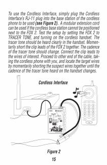
To use the Cordless Interface, simply plug the CordlessInterface’s RJ-11 plug into the base station of the cordlessphone to be used (see Figure 2). A modular extension cordcan be used if the cordless base station cannot be positionednext to the FOX 2. Test the setup by setting the FOX 2 toTRACER TONE, and turning on the cordless handset. Thetracer tone should be heard clearly in the handset. Momen-tarily short the clip leads of the FOX 2 together. The cadenceof the tracer tone should change. Connect the clip leads tothe wires of interest. Proceed to other end of the cable, tak-ing the cordless phone with you, and locate the target wiresby momentarily shorting the suspect wires together until thecadence of the tracer tone heard on the handset changes.
Figure 2
TRACER TONE
VISUAL CONT.TALK
OFF / POLARITY
AUDIBLE CONT.WARBLE
PULSE
CORDLESSINTERFACE
OVERLOAD PROTECTED
UNLOCK BATTERY TEST
AC / RING
TRIPLETT
REV NORM
Cordless Interface

16
If testing sensors on a security system, the user can con-nect the FOX 2 to the wire pair of interest, proceed to thelocation of the sensor with the cordless handset, actuate thesensor, and listen for the cadence change on the handset.For example, a door or window can be opened and closed toactuate its magnetic sensor, which is verified by the cadencechange.120VAC Warning:The FOX 2 provides an audible warning that 120VAC hasbeen connected to the product. This is intended to providethe user with a warning that an unexpected potentially dan-gerous voltage is present. This feature works in all testmodes. When activated, the FOX 2 begins beeping on andoff. The 9 volt battery must be good for this feature to work.See the Safety Warnings and Cautions section for additionalinformation concerning this feature.120VAC Protection:The FOX 2 is 120VAC line cross resistant. This means that inthe great majority of cases, the FOX 2 will tolerate the acci-dental application of 120VAC without damage. This featureworks in all modes. The 9 volt battery is not required for thisto work.
See the Safety Warnings and Cautions section for additionalinformation concerning this feature.
17
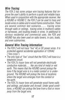
Wire Tracing:The FOX 2 has some unique wire tracing features that im-prove the user’s ability to perform a quick and reliable trace.When used in conjunction with the appropriate receiver, likea HOUND or HOUND 2, the FOX 2 can be used to trace andlocate wires in cables and in wood frame construction. Thereare several common test scenarios........ tracing wiresthrough walls or ceilings, tracing wires in multiwire cablesor harnesses, and locating breaks in wires. In additional toobvious residential and commercial uses, the FOX andHOUND has also been used on radio towers, in cars, boats,and even submarines.
General Wire Tracing Information:• The FOX 2 will not trace “live” AC or DC power wires. It is protected against accidental application of 120VAC (“line cross”).• The only type of “live” circuit that the FOX 2 will trace is a telephone circuit.• The FOX 2’s tracer tone will not penetrate electrically conductive materials...... like any kind of metal or wet earth. This means that the HOUND cannot pickup the tone if the target wire is in a metal conduit or is under- ground. The HOUND will pickup the tone at locations where the target wire emerges from the conduit or the earth.• The FOX 2’s tracer tone will penetrate wood frame walls and ceilings, and plaster and drywall. Under good condi- tions, a HOUND can pickup the tone from a foot or more away from the target wire.
18
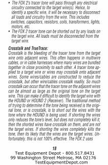
• The FOX 2’s tracer tone will pass through any electrical circuitry connected to the target wire(s). Hence, to identify a specific wire, it will be necessary to disconnect all loads and circuitry from the wire. This includes switches, capacitors, resistors, coils, transformers, lights, motors, etc.• The FOX 2 tracer tone can be shorted out by any loads on the target wire. All loads must be disconnected from the target wire.Crosstalk and TrueTrace:Crosstalk is the bleeding of the tracer tone from the targetwire onto adjacent wires. This often happens in multiwirecables, or in cable harnesses where many wires are bundledtogether in close proximity to each other. A tracer tone ap-plied to a target wire or wires may crosstalk onto adjacentwires. Some wires/cables are constructed to reduce thecrosstalk, but other wire/cables crosstalk readily. So muchcrosstalk can occur that the tracer tone on the adjacent wirescan be almost as large as the original tone on the targetwire. This can make it difficult to identify the target wire withthe HOUND or HOUND 2 (Receiver). The traditional methodof trying to determine if the tone being received is the origi-nal tone, or is crosstalk, is to short out the wires with thetone where the HOUND is being used. If shorting the wiresonly reduces the tone’s level, but does not completely kill it,then the shorted wires have crosstalk on them, and are notthe target wires. If shorting the wires completely kills thetone, then its likely that the wires are the target wires. Un-fortunately, this is not 100% effective. The FOX 2 uses
Test Equipment Depot - 800.517.8431 99 Washington Street Melrose, MA 02176
TestEquipmentDepot.com
19
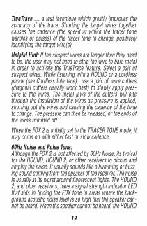
TrueTrace .... a test technique which greatly improves theaccuracy of the trace. Shorting the target wires togethercauses the cadence (the speed at which the tracer tonewarbles or pulses) of the tracer tone to change, positivelyidentifying the target wire(s).
Helpful Hint: If the suspect wires are longer than they needto be, the user may not need to strip the wire to bare metalin order to activate the TrueTrace feature. Select a pair ofsuspect wires. While listening with a HOUND or a cordlessphone (see Cordless Interface), use a pair of wire cutters(diagonal cutters usually work best) to slowly apply pres-sure to the wires. The metal jaws of the cutters will bitethrough the insulation of the wires as pressure is applied,shorting out the wires and causing the cadence of the toneto change. The pressure can then be released, or the ends ofthe wires trimmed off.When the FOX 2 is initially set to the TRACER TONE mode, itmay come on with either fast or slow cadence.60Hz Noise and Pulse Tone:Although the FOX 2 is not affected by 60Hz Noise, its typicalfor the HOUND, HOUND 2, or other receivers to pickup andamplify the noise. It usually sounds like a humming or buzz-ing sound coming from the speaker of the receiver. The noiseis usually at its worst around fluorescent lights. The HOUND2, and other receivers, have a signal strength indicator LEDthat aids in finding the FOX tone in areas where the back-ground acoustic noise level is so high that the speaker can-not be heard. When the speaker cannot be heard, the HOUND
20
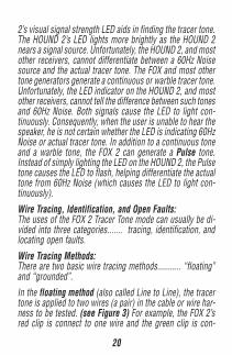
2’s visual signal strength LED aids in finding the tracer tone.The HOUND 2’s LED lights more brightly as the HOUND 2nears a signal source. Unfortunately, the HOUND 2, and mostother receivers, cannot differentiate between a 60Hz Noisesource and the actual tracer tone. The FOX and most othertone generators generate a continuous or warble tracer tone.Unfortunately, the LED indicator on the HOUND 2, and mostother receivers, cannot tell the difference between such tonesand 60Hz Noise. Both signals cause the LED to light con-tinuously. Consequently, when the user is unable to hear thespeaker, he is not certain whether the LED is indicating 60HzNoise or actual tracer tone. In addition to a continuous toneand a warble tone, the FOX 2 can generate a Pulse tone.Instead of simply lighting the LED on the HOUND 2, the Pulsetone causes the LED to flash, helping differentiate the actualtone from 60Hz Noise (which causes the LED to light con-tinuously).Wire Tracing, Identification, and Open Faults:The uses of the FOX 2 Tracer Tone mode can usually be di-vided into three categories....... tracing, identification, andlocating open faults.
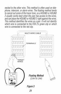
Wire Tracing Methods:There are two basic wire tracing methods........... “floating”and “grounded”.In the floating method (also called Line to Line), the tracertone is applied to two wires (a pair) in the cable or wire har-ness to be tested. (see Figure 3) For example, the FOX 2’sred clip is connect to one wire and the green clip is con-
21
nected to the other wire. This method is often used on tele-phone, intercom, or alarm wires. The floating method tendsto cancel out some of the tracer tone, so a HOUND or HOUND2 usually works best when the user has access to the wires,and can place the HOUND or HOUND 2 right against the wires.This method identifies the wires as a pair. It will not identifywhich wire is connected to the FOX 2’s green clip or whichwire is connected to the red clip.
Figure 3
TRACER TONE
VISUAL CONT.TALK
OFF / POLARITY
AUDIBLE CONT.WARBLE
PULSE
CORDLESSINTERFACE
OVERLOAD PROTECTED
UNLOCK BATTERY TEST
AC / RING
TRIPLETT
REV NORM
PUSH
ON/OFF
– VOLUME +
Floating Method(Line to Line)
22
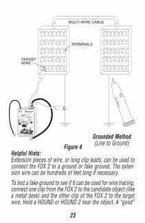
For positive identification of the pair, momentarily short thepair to active the TrueTrace feature. If this is the target pair,the cadence of the tracer tone will change.In the grounded method (also called Line to Ground), oneclip of the FOX 2 (either the red or green) is connected toearth ground or a “fake ground”, and the other clip is con-nected to the target wire. The target wire can be one wire ofa pair or a multiwire cable. (see Figure 4) This method cre-ates the strongest tracer tone, and is often used when wiresare traced through walls or ceiling. It is also useful for iden-tifying a specific wire within a bundle of wires. If connectionto a true ground is not available, a large metal object can beused as a fake ground. For example, a large metal desk or ametal file cabinet can be used. When tracing wires in a car,trailer, or RV, etc. the metal frame or body can be used as aground. When tracing wires in a boat (that is in the water)with a wood or fiberglass glass hull, any piece of metal thatcomes in contact with the water can be used as a ground.Simply connect one clip of the FOX 2 to the ground or fakeground, and the other clip to the target wire.TrueTrace can be used in conjunction with the groundedmethod of tracing if the ground that is used at the FOX 2location is also available at the end location of the wires.Simply short each suspect wire to the ground while listen-ing for a cadence change with a HOUND or HOUND 2. Ifwater is used as the fake ground, it usually is not conductiveenough to activate TrueTrace.
23
Figure 4Helpful Hints:Extension pieces of wire, or long clip leads, can be used toconnect the FOX 2 to a ground or fake ground. The exten-sion wire can be hundreds of feet long if necessary.
To test a fake ground to see if it can be used for wire tracing,connect one clip from the FOX 2 to the candidate object (likea metal desk) and the other clip of the FOX 2 to the targetwire. Hold a HOUND or HOUND 2 near the object. A “good”
TRACER TONE
VISUAL CONT.TALK
OFF / POLARITY
AUDIBLE CONT.WARBLE
PULSE
CORDLESSINTERFACE
OVERLOAD PROTECTED
UNLOCK BATTERY TEST
AC / RING
TRIPLETT
REV NORM
PUSH
ON/OFF
– VOLUME +
Grounded Method(Line to Ground)
24
fake ground will not radiate much tracer tone. The tracertone should be much stronger on the FOX 2’s other clip. If itis not, the target wire may be shorted to ground, or the fakeground may not be adequate. Generally, the larger the ob-ject used as the fake ground, the better it works.
If the target wire is somehow connected to ground, this willgreatly reduce or kill the tracer tone.
Telephone Wires:The floating method is usually used to locate a pair of wiresin a telephone junction block. If the wires are already termi-nated into a modular telephone jack, simply plug the FOX 2into the jack (using the RJ-45 to RJ-11 Adapter). Thismethod works with the phone line connected or disconnectedfrom the wires going to the telephone company. A strongertrace is usually obtained if the wires are not connected tothe telephone company.If the wires are not connected to the telephone company,the grounded method can be used to trace telephone wiresthrough a wall or ceiling. Use the green and red clips to con-nect to the phone line and ground.To identify the wires, if using the floating method, momen-tarily short the target wires together to active TrueTrace, andlisten for the cadence change. If it changes, you’ve foundthe target pair. If no change occurs, keep searching.
To identify the wires, if using the grounded method, mo-mentarily short the target wire to ground to active TrueTrace,and listen for the cadence change. If it changes, you’ve found
Test Equipment Depot - 800.517.8431 99 Washington Street Melrose, MA 02176
TestEquipmentDepot.com
25
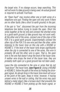
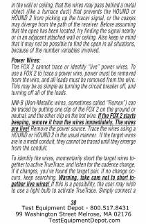
the target wire. If no change occurs, keep searching. Thiswill not work if a fake ground is being used. An actual groundis required to activate TrueTrace.An “Open Fault” may involve either one or both wires of atelephone wire pair. Finding the open will only work if thereare no other faults (like a short to earth ground) in the pair.If the pair is “live”, disconnect the pair from the incomingtelephone line before trying to locate the open. Short thewires together at the far end and connect the shorted wiresto a good earth ground (a fake ground may not work well).At the other end of the wires, connect one of the clips of theFOX 2 to a good earth ground. Experimentally connect theother clip of the FOX 2 to one wire and then the other, whilelistening to the tracer tone on this clip with a HOUND orHOUND 2. If the level of the tracer tone drops significantlywhen the clip is connected to one of the wires, this wire isprobably OK and the other wire is open. That is, the openwire is the one that doesn’t drop the level of the tracer tone.If neither wire drops the level of the tracer tone, they areprobably both open (or a good ground has not been used).
Leave the clip connected to the wire or wires that do not“load down” the tracer tone. (see Figure 5) Using a HOUNDor HOUND 2, follow the path of the wires by finding the stron-gest signal. An abrupt drop in the tracer tone level will occurat the point of the open. Keep in mind, however, if tracingunseen wires in the wall or ceiling, that the wires may passbehind a metal object (like a furnace duct) that prevents theHOUND or HOUND 2 from picking up the tracer signal, or
26
the wires may diverge from the path of the receiver. Beforeassuming that the open has been located, try finding thesignal nearby or in an adjacent attached wall or ceiling. Alsokeep in mind that it may not be possible to find the open inall situations, because of the number variables involved.
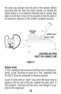
LOCATING AN OPENFAULT IN A SINGLE LINE
Figure 5
Helpful Hints:A “live” telephone line prevents TrueTrace from working cor-rectly. To get TrueTrace to work on a “live” telephone line,the FOX 2 must be connected in Reverse polarity.A pair of wires with an “open” may allow the tracer tone toappear at the far end of the pair, despite the open fault. Inthis situation, TrueTrace will not work, even though it is ap-plied to the target pair.
TRACER TONE
VISUAL CONT.TALK
OFF / POLARITY
AUDIBLE CONT.WARBLE
PULSE
CORDLESSINTERFACE
OVERLOAD PROTECTED
UNLOCK BATTERY TEST
AC / RING
TRIPLETT
REV NORM
PUSH ON/OFF
– VOLU
ME +STRONGTONE
OPEN FAULT
WEAK TONE
27
Do not insert a telephone modular plug (RJ-11) directly intothe jack (RJ-45) on the FOX 2. Doing so can damage thejack, resulting in reduced capability when using the FOX 2 totrace LAN cables. Always use the provided RJ-45 to RJ-11Adapter to trace or test polarity of telephone wires termi-nated into a modular jack or plug.If attempting to trace a telephone wire terminated in a modu-lar jack, but not connected to the telephone company, througha wall or ceiling, insert the FOX 2’s RJ-11 into the jack, andthen connect either the red or green clip lead to a ground orfake ground. This will boost the tracer tone, and may pro-vide an adequate trace. The strongest trace will be obtainedwhen using the grounded method and the clips (as describedabove), but if the hint works, the user won’t have to openthe modular jack housing to gain access to the wires.
Coaxial Cable:Coaxial cable, like that used for cable TV, satellite TV, closedcircuit TV, early LAN systems, etc. is often connected to othercables through splitters, combiners, or amplifiers. In orderto trace the cable, it must be disconnected from these“loads”. Since coaxial cable is self-shielding, the floatingmethod usually does not work well when tracing the cable.It can be done, but the HOUND or HOUND 2 must be heldvery close to the end of the cable to pick up any signal. Toapply a floating signal to a coax, connect one clip of the FOX2 to the center conductor of the coax, and the other clip tothe shield of the coax.
28
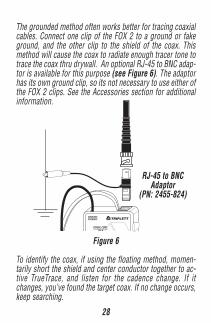
The grounded method often works better for tracing coaxialcables. Connect one clip of the FOX 2 to a ground or fakeground, and the other clip to the shield of the coax. Thismethod will cause the coax to radiate enough tracer tone totrace the coax thru drywall. An optional RJ-45 to BNC adap-tor is available for this purpose (see Figure 6). The adaptorhas its own ground clip, so its not necessary to use either ofthe FOX 2 clips. See the Accessories section for additionalinformation.
Figure 6
To identify the coax, if using the floating method, momen-tarily short the shield and center conductor together to ac-tive TrueTrace, and listen for the cadence change. If itchanges, you’ve found the target coax. If no change occurs,keep searching.
VISUAL CONT.TALK
CORDLESSINTERFACE TRIPLETT
RJ-45 to BNCAdaptor
(PN: 2455-824)
29
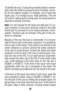
To identify the coax, if using the grounded method, momen-tarily short the shield to ground to active TrueTrace, and lis-ten for the cadence change. If it changes, you’ve found thetarget coax. If no change occurs, keep searching. This willnot work if a fake ground is being used. An actual ground isrequired to activate TrueTrace.Note: It is not unusual for the loose turn-able part of a co-axial connector to have poor electrical contact to the cableshield until it is screwed on to its mating connector. Conse-quently, TrueTrace may not activate if this part of the con-nector is contacted.Because of the way that coax is constructed, it is not pos-sible to find an open in the center conductor. It is possible tofind an open in the shield, if the shield is not shorted to thecenter conductor or ground. Connect the center conductorof the coax to earth ground. Connect the shield and centerconductor at the far end of the coax to earth ground. Con-nect one clip of the FOX 2 to an earth ground. Experimen-tally connect the other clip of the FOX 2 to the shield of thecoax, while listening to the tracer tone on this clip with aHOUND or HOUND 2. If the level of the tracer tone dropssignificantly when the clip is connected to the shield, theshield is probably grounded and can’t be traced to the open.
If the level of the tracer tone doesn’t drop much, leave theclip connected to shield. Using a HOUND or HOUND 2, fol-low the path of the coax by finding the strongest signal. Anabrupt drop in the tracer tone level will occur at the point ofthe open. Keep in mind, however, if tracing unseen coaxes
30
in the wall or ceiling, that the wires may pass behind a metalobject (like a furnace duct) that prevents the HOUND orHOUND 2 from picking up the tracer signal, or the coaxesmay diverge from the path of the receiver. Before assumingthat the open has been located, try finding the signal nearbyor in an adjacent attached wall or ceiling. Also keep in mindthat it may not be possible to find the open in all situations,because of the number variables involved.
Power Wires:The FOX 2 cannot trace or identify “live” power wires. Touse a FOX 2 to trace a power wire, power must be removedfrom the wire, and all loads must be removed from the wire.This may be as simple as turning the circuit breaker off, andturning off all of the loads.NM-B (Non-Metallic wires, sometimes called “Romex”) canbe traced by putting one clip of the FOX 2 on the ground orneutral, and the other clip on the hot wire. If the FOX 2 startsbeeping, remove it from the wires immediately. The wiresare live! Remove the power source. Trace the wires using aHOUND or HOUND 2 in the usual manner. If the target wiresare in a metal conduit, they cannot be traced until they emergefrom the conduit.To identify the wires, momentarily short the target wires to-gether to active TrueTrace, and listen for the cadence change.If it changes, you’ve found the target pair. If no change oc-curs, keep searching. Warning, take care not to short to-gether live wires! If this is a possibility, the user may wishto use a light bulb to activate TrueTrace. Simply connect a
Test Equipment Depot - 800.517.8431 99 Washington Street Melrose, MA 02176
TestEquipmentDepot.com
31
120VAC incandescent bulb (any wattage) across the wires.If it lights, the line is live, if the cadence changes, the targetwire has been located, if nothing happens, keep searching.An adapter with a standard lightbulb base and clip leads canbe purchased at your local hardware store.Resistance Heating Wires:The FOX 2 and a HOUND or HOUND 2 can be used to tracethe path of a resistance heating wire in a plaster wall or ceil-ing. This is usually performed to find an open in the wire. Itis best if the user is familiar with resistance heating tech-niques, particularly in regard to the typical patterns used forthe wire path. The wire is usually in a serpentine pattern,with the wire spacing and orientation varying depending onthe amount of heat needed in different areas of the room.
Finding the open can be a challenge. Several techniques canbe, and should be, used.
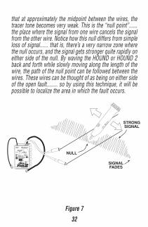
It helps if the user performs a few experiments before tryingto find the open. (see Figure 7) Attach a few pieces of wire(any kind) more than several feet long to each clip of theFOX 2. Lay the wires out on a non-conducting surface (awood floor with no metal in the vicinity..... nails are OK, butmake sure there’s no metal furnace duct below the floor)parallel to each other, about 4“ apart. Using a HOUND orHOUND 2, trace along one of the wires, in normal fashion,noting how the tracer tone becomes stronger as the wire isapproached. Now trace along the other wire, noting that itbehaves just like the previous wire. Now, slowing move theHOUND or HOUND 2 from one wire to the other wire. Notice
32
that at approximately the midpoint between the wires, thetracer tone becomes very weak. This is the “null point”......the place where the signal from one wire cancels the signalfrom the other wire. Notice how this null differs from simpleloss of signal...... that is, there’s a very narrow zone wherethe null occurs, and the signal gets stronger quite rapidly oneither side of the null. By waving the HOUND or HOUND 2back and forth while slowly moving along the length of thewire, the path of the null point can be followed between thewires. These wires can be thought of as being on either sideof the open fault........ so by using this technique, it will bepossible to localize the area in which the fault occurs.
Figure 7
TRACER TONE
VISUAL CONT.TALK
OFF / POLARITY
AUDIBLE CONT.WARBLE
PULSE
CORDLESSINTERFACE
OVERLOAD PROTECTED
UNLOCK BATTERY TEST
AC / RING
TRIPLETT
REV NORM
PUSH ON/OFF
– VOLU
ME +
STRONGSIGNAL
NULL
SIGNALFADES
33
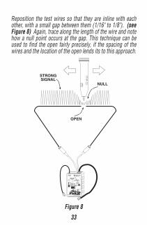
Reposition the test wires so that they are inline with eachother, with a small gap between them (1/16" to 1/8"). (seeFigure 8) Again, trace along the length of the wire and notehow a null point occurs at the gap. This technique can beused to find the open fairly precisely, if the spacing of thewires and the location of the open lends its to this approach.
Figure 8
PUSHON/OFF
– VO
LUM
E +
STRONGSIGNAL
OPEN
TRACER TONE
VISUAL CONT.TALK
OFF / POLARITY
AUDIBLE CONT.WARBLE
PULSE
CORDLESSINTERFACE
OVERLOAD PROTECTED
UNLOCK BATTERY TEST
AC / RING
TRIPLETT
REV NORM
NULL
34
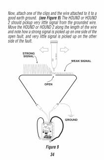
Now, attach one of the clips and the wire attached to it to agood earth ground. (see Figure 9) The HOUND or HOUND2 should pickup very little signal from the grounded wire.Move the HOUND or HOUND 2 along the length of the wireand note how a strong signal is picked up on one side of theopen fault, and very little signal is picked up on the otherside of the fault.
Figure 9
PUSHON/OFF
– VO
LUM
E +
STRONGSIGNAL
OPEN
TRACER TONE
VISUAL CONT.TALK
OFF / POLARITY
AUDIBLE CONT.WARBLE
PULSE
CORDLESSINTERFACE
OVERLOAD PROTECTED
UNLOCK BATTERY TEST
AC / RING
TRIPLETT
REV NORM
WEAK SIGNAL
GROUND
35
For the most accurate simulation, lay out a serpentine pat-tern on the floor similar to that in a ceiling, and try to locatean open using the nulling and the grounding technique. Havean assistant position the open fault while you are out of theroom, and then cover the wire with cardboard, newspaper,plywood, etc..... and see if you can find the open. You’ll prob-ably find that the open is sometimes found in the wrongplace. Notice what wire configuration causes this to happenand experiment with the nulling and grounding techniquesto see if a method can be figured out that will work in thesesituations.
To test the actual resistance heating circuit, disconnect theends of the heating wires from the power source. This canusually be done at the thermostat that controls the room.Attach the clips of the FOX 2 to the wires (one clip to eachwire) and use the nulling and grounding techniques dis-cussed above, and any other methods learned from your ex-periments, to find the open fault.
Cars:Wires can be traced in cars or similar metal bodied vehiclesusing the grounded method. The metal body of the car actsas a ground, and as a shield. This means that, compared totracing in a wood frame structure, it will be necessary toplace the HOUND or HOUND 2 closer to the target wire topick up a tracer tone.Connect one clip of the FOX 2 to the metal chassis of the car,and the other clip to the wire to be traced. As in other appli-cations, the far end of the wire must be disconnected from
36
any loads or any other wires, or the tracer tone will be shortedout, or it will migrate into other wires. Because wires adja-cent to the target wire will often acts as shields, and be-cause the wires in cars are often bundled together into har-nesses, it may be difficult to follow the target wire throughthe harness. Try to locate the wire as it emerges from theharness.Use the TrueTrace feature to identify the target wire. Shortthe suspect wires to the metal chassis to activate TrueTrace,and listen for the cadence change. If more than one wirecauses the cadence to change, the wires are somehow con-nected together, either through a short or through a load(like a light bulb, a switch, a motor, etc.).Find an open fault by tracing along the wire until the tracertone drops dramatically in level. Shorting the far end of theopen wire to chassis ground may help. If the wire is bundledin a harness, it may be difficult, if not impossible to locatethe open without unbundling the harness. In these cases, itis sometimes more expedient to run a new wire to replacethe open wire.
Boats:Wiring tracing on metal hulled boats is similar to tracingwires in cars (see above).If tracing wires in a boat with a non-conductive hull (woodor fiberglass) that is in the water, the grounded method canbe used, but the water will act as the ground. Attach one clipof the FOX 2 to a metal object that is in contact with the
Test Equipment Depot - 800.517.8431 99 Washington Street Melrose, MA 02176
TestEquipmentDepot.com
37
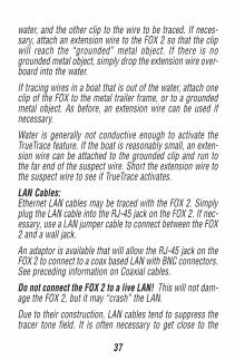
water, and the other clip to the wire to be traced. If neces-sary, attach an extension wire to the FOX 2 so that the clipwill reach the “grounded” metal object. If there is nogrounded metal object, simply drop the extension wire over-board into the water.
If tracing wires in a boat that is out of the water, attach oneclip of the FOX to the metal trailer frame, or to a groundedmetal object. As before, an extension wire can be used ifnecessary.Water is generally not conductive enough to activate theTrueTrace feature. If the boat is reasonably small, an exten-sion wire can be attached to the grounded clip and run tothe far end of the suspect wire. Short the extension wire tothe suspect wire to see if TrueTrace activates.
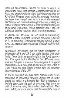
LAN Cables:Ethernet LAN cables may be traced with the FOX 2. Simplyplug the LAN cable into the RJ-45 jack on the FOX 2. If nec-essary, use a LAN jumper cable to connect between the FOX2 and a wall jack.
An adaptor is available that will allow the RJ-45 jack on theFOX 2 to connect to a coax based LAN with BNC connectors.See preceding information on Coaxial cables.Do not connect the FOX 2 to a live LAN! This will not dam-age the FOX 2, but it may “crash” the LAN.Due to their construction, LAN cables tend to suppress thetracer tone field. It is often necessary to get close to the
38
cable with the HOUND or HOUND 2 to locate or trace it. Toincrease the tracer tone strength, connect either clip of theFOX 2 to a ground while the target cable is connected to theRJ-45 jack. However, when using this grounded technique,the tracer tone strength may be so dramatically increasedthat the tone will crosstalk onto adjacent cables, making thepath of the target cable difficult to differentiate from the pathof the other LAN cables. This is especially true if the LANcables are bundled together, which promotes crosstalk.To identify the LAN cable, pair 4/5 must be momentarilyshorted to active TrueTrace. These are the center 2 pins onan RJ-45 connector. These can be shorted out with a smallwire..... or a special user constructed plug/jack made for thispurpose.Specialized LAN testers, like the Triplett PairMaster orWireMaster XR-5 and XR-2 can easily identify LAN cablefaults. These faults are usually right at the RJ-45 connec-tors. If an open fault is identified in the LAN cable, makesure that the open is in one of the active pairs. In a typical568A/B CAT 5 LAN, only pairs 3/6 and 4/5 are used. Pairs 1/2 and 7/8 are not used. Opens in these pairs will not affectthe performance of the LAN.To find an open fault in a LAN cable, first check the RJ-45connectors on the ends of the cable. If these are OK, somespecial test cables, or a Break Out Box (BOB) is necessary tofind the open along the path of the cable. First, trace thepath of the cable using the pre-described methods. Theninsert a BOB, our use a special cable to connect the clips of
39
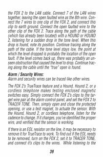
the FOX 2 to the LAN cable. Connect 7 of the LAN wirestogether, leaving the open faulted wire as the 8th wire. Con-nect the 7 wires to one clip of the FOX 2, and connect thisclip to earth ground. Connect the open faulted wire to theother clip of the FOX 2. Trace along the path of the cable(which has already been located) with a HOUND or HOUND2, listening for a sudden drop in the tone level. When thisdrop is found, note its position. Continue tracing along thepath of the cable. If the tone level stays low, the point atwhich the level dropped is probably the location of the openfault. If the level comes back up, there was probably an un-seen obstruction that caused the level to drop. Continue trac-ing along the cable until the “true” open is found.Alarm / Security Wires:Alarm and security wires can be traced like other wires.
The FOX 2’s TrueTrace feature and a Hound, Hound 2, or acordless telephone makes testing enclosed magneticswitches easy. Simply connect the FOX 2’s clips to the tar-get wire pair at the alarm control panel, and set the FOX 2 toTRACER TONE. Then, simply open and close the protectedopening, or use a test magnet, to actuate the sensor. Withthe Hound, Hound 2, or cordless telephone, listen for thecadence to change. If it changes, you’ve identified the properwire, and verified that the sensor is working.If there is an EOL resistor on the line, it may be necessary toremove it for TrueTrace to work. To find out if the EOL needsto be removed, turn on the FOX 2, set it to TRACER TONE,and connect it’s clips to the wires. While listening to the
40
FOX 2’s pilot tone, short the clips together several times,noting whether the cadence changes. If it does, the EOL canbe left on the line. If the cadence does not change, the EOLmust be removed.The TrueTrace feature doubles as a unique latch tester, en-abling a feature called Trip-Latch. Unlike many latch testers,which require the user to be near the latch tester to deter-mine if the circuit being tested has sent a “pulse”, Trip-Latchallows the user to be near the alarm sensor, in its installedlocation, and determine if the sensor is sending a pulse tothe alarm control panel. This feature works with sensors thathave N.O. (Normally Open) or N.C. (Normally Closed) out-puts, but the pulse output must last for 1 second or more.The use of a Hound, Hound 2, or cordless telephone is re-quired.
If testing a N.O. contact, a Hound, Hound 2, or cordless tele-phone may be used. If testing a N.C. contact, a cordless tele-phone must be used.To understand how this feature works, a few simple experi-ments are suggested. Turn on the FOX 2, setting it to TRACERTONE. Using a Hound, Hound 2, or a cordless telephone,listen to the cadence of the Tone….. or if the audio pilot toneis activated, simply listen to the FOX 2 itself. Short the clipleads together for about 1 second. Notice how the FOX 2’scadence changes. When the clips are shorted together, thecadence changes almost immediately, and stays at its newcadence when the clips are unshorted. Hence, in a N.O. cir-cuit, in response to a momentary short, the cadence changes
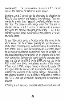
41
permanently….. i.e. a momentary closure in a N.O. circuitcauses the cadence to “latch” to a new speed.
Similarly, an N.C. circuit can be simulated by shorting theFOX 2’s clips together and keeping them shorted. Then mo-mentarily, greater than 1 second, un-short and then re-shortthe clips. The cadence will change when the clips are re-shorted. Hence, in a N.C. circuit, in response to a momen-tary open, the cadence changes permanently….. i.e. a mo-mentary open in a N.C. circuit causes the cadence to’“latch”to a new speed.
To use Trip-Latch, go to a location when the wires to thealarm sensor can be accessed (usually at a junction box orat the alarm control panel), and temporarily disconnect theN.O. or N.C. wire(s) from the control panel. Leave the powerto the sensor connected. Connect the clips of the FOX 2 tothe disconnected sensor wire(s), or, on sensors with a com-mon connection between the power and the contacts, con-nect one clip of the FOX 2 to the COM and one clip to theN.O. or N.C. wire. Go to the installed location of the sensor.If the circuit is N.O., using a Hound or Hound 2, locate FOX2’s signal near the sensor, and then trip the sensor, notingwhether the cadence of the signal changes. Alternately, ifthe situation permits it, use a cordless telephone to listen tothe FOX 2, and trip the sensor, listening for the cadence tochange.If testing a N.C. sensor, a cordless telephone must be used.
42
Miscellaneous Multiwire Cables:Some general principles are important to keep in mind whenlocating and tracing wires and cables.Any wire with a signal on it, which runs parallel to anotherwire or wires tends to couple its signal to the other wires.The closer the wires are together, and the longer the parallelrun, the more signal that is coupled. This situation occurs inmultiwire cables, and when cables are bundled together wheninstalled.Luckily, if the other wires are low impedance (they have loadson them), the coupled signal will be lower in level. So, ingeneral its best to disconnect the cable being traced fromits loads, leaving other paralleling cables still connected totheir loads. If the other cables do not have loads (like whenthey are being installed), it helps to temporarily connect oneend of the cable to earth ground, so that they do not inter-fere with the trace.
The loading effect can also be used when trying to locate anopen fault in a wire in a multiwire cable. By leaving the loadson the unfaulted wires, the tracer tone will be reduced inlevel on the unfaulted wires, and make locating the openeasier. In fact, if the other wires are unconnected, it helps totemporarily connect them to earth ground, so that they sup-press the effect of the coupled signals. It may also help toconnect the far end of the open faulted wire to earth ground.Doing this will produce the most distinct change in tracertone level when the HOUND or HOUND 2 passes over thelocation of the open.
Test Equipment Depot - 800.517.8431 99 Washington Street Melrose, MA 02176
TestEquipmentDepot.com
43
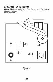
Setting the FOX 2’s Options:Figure 10 shows a diagram of the locations of the internaloptions jumpers.
J1
J3
J6
J4
Figure 10
44
Here’s what the jumpers do:J1: Turns the TrueTrace feature on and off In some cases, the user may find that TrueTrace doesn’t behave as desired. TrueTrace is on when the jumper is in the DOWN position, and off when the jumper is in the UP position.J3: Sets the pitch range of the Tracer Tone With the jumper in place, the pitch is low. With the jumper removed, the pitch is high. The user may select whichever pitch is most pleasing. Some receivers (inductive amplifiers) work better with a particular pitch setting. The high pitch setting produces a more piercing tracing tone, which may be useful in locations with a lot of acoustic noise.
J4: Turns the Pilot Tone on and off The FOX 2 generates a pilot tone in the TRACER TONE mode. This is a low volume tone that sounds like the TRACER TONE. It is often helpful to the user, in some cases eliminating the need for a HOUND or HOUND 2. It also reminds the user that the FOX 2 is on and operating. Some users may find the pilot tone annoying, or may find it inappropriate for the test situation (like in a quiet office or a library). Removing J4 turns the pilot tone off.
45
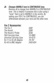
J6: Changes WARBLE tone to CONTINUOUS tone. Remove J6 to change from WARBLE to CONTINUOUS tone. This is helpful if someone else is also using a “toner” that is set to WARBLE in the vicinity. By setting your FOX 2 to CONTINUOUS, you can differentiate between your tone and the other tone.
Fox 2 Accessories:The Fox 2 3382The Hound 3390The Hound 2 Probe 3236F&H Carrying Case 10-3983Universal Carrying Case 10-4275RJ-11 to RJ-45 Adaptor 79-797RJ-45 to BNC Adaptor 2455-824

46
ONE YEAR LIMITED WARRANTYThe Triplett Corporation warrants instruments and test equipmentmanufactured by it to be free from defective material or workman-ship and agrees to repair or replace such products which, undernormal use and service, disclose the defect to be the fault of ourmanufacturing, with no charge within one year of the date of originalpurchase for parts and labor. If we are unable to repair or replacethe product, we will make a refund of the purchase price. Consultthe Instruction Manual for instructions regarding the proper use andservicing of instruments and test equipment. Our obligation underthis warranty is limited to repairing, replacing, or making refund onany instrument or test equipment which proves to be defective withinone year from the date of original purchase.
This warranty does not apply to any of our products which have beenrepaired or altered by unauthorized persons in any way so as, in oursole judgment, to injure their stability or reliability, or which havebeen subject to misuse, abuse, misapplication, negligence, accidentor which have had the serial numbers altered, defaced, or removed.Accessories, including batteries and fuses, not of our manufactureused with this product are not covered by this warranty.
To register a claim under the provisions of this warranty, return theinstrument or test equipment to Triplett Corporation, Service De-partment, One Triplett Drive, Bluffton, Ohio 45817, transportationprepaid. Upon our inspection of the product, we will advise you asto the disposition of your claim.

47
ALL WARRANTIES IMPLIED BY LAW ARE HEREBY LIMITED TO APERIOD OF ONE YEAR FROM DATE OF PURCHASE, AND THE PRO-VISIONS OF THE WARRANTY ARE EXPRESSLY IN LIEU OF ANYOTHER WARRANTIES EXPRESSED OR IMPLIED.
The purchaser agrees to assume all liability for any damages andbodily injury which may result from the use or misuse of the prod-uct by the purchaser, his employees, or others, and the remediesprovided for in this warranty are expressly in lieu of any other liabil-ity Triplett Corporation may have, including incidental or consequen-tial damages.
Some states (USA ONLY) do not allow the exclusion or limitation ofincidental or consequential damages, so the above limitation or ex-clusion may not apply to you. No representative of Triplett Corpora-tion or any other person is authorized to extend the liability of TriplettCorporation in connection with the sale of its products beyond theterms hereof.
Triplett Corporation reserves the right to discontinue models at anytime, or change specifications, price or design, without notice andwithout incurring any obligation.
This warranty gives you specific legal rights, and you may have otherrights which vary from state to state.

48
Test Equipment Depot - 800.517.8431 99 Washington Street Melrose, MA 02176
TestEquipmentDepot.com