Embed Size (px)
Citation preview

PNEUMATIC CUTTING UNIT
USE MANUAL
FP100 FP100
2EN
COMPANY
ACKNOWLEDGMENT
Rasor® Elettromeccanica S.r.l. was established in Milan in 1946 by the two promoting partnersSpinelli and Ciminaghi. For more than sixty years it has been producing automatic cuttingsystems, cutting units for textile applications and electric and pneumatic cutters.
Initially considered as a point of reference for cutting systems in thetextile applications, the Rasor® products are nowadays widely used inother fields: chemical, automotive, nautical and sport sectors and infurniture manufacturing.Rasor® can rely on the professional continuity of three generations,
thanks to the precious support of the promoting partner, to his passion, dedication andgreat experience of seventy years.The main characteristic of Rasor® is that each working phase, starting from the manufacturingof the product up to its packing and delivery is carried out in Rasor® premises by qualifiedoperators who have professionaly grown up following the spirit of the company and of itsfounders. This ensures the high quality which Rasor® has always considered as essentialsince the beginning of its activity.Following the innovative spirit mentioned above, our company is constantly focused on theimprovement of the product quality, on the study and development of new materials andtechnologies.
Dear Customer,thank you for choosing a Rasor® Elettromeccanica S.r.l. product.Rasor® has been a reference point in the field of cutting systems in the textile, clothing,furniture, tailoring, sport, chemical, automotive, nautical and insulating material sectors foryears.Its production has been always synonymous with reliability attested by many of satisfiedcustomers.Rasor® quality system supervises all the company activities in order to provide the Customerwith a service that meets its needs and expectations in terms of product quality, deliveryreliability and stock of finished products.All the parts of the devices have been planned and produced to guarantee an optimumperformance. In order to keep the high quality level and the long reliabilty of the Rasor®
products, it is recommended to use only original spare parts and to contact the headoffice for any maintenance work.
EN3
1. GENERAL SAFETY RULES
This manual is an integral part of cutting unit FP 100 and must be carefullyread before using it since it gives important indications with regards to its safeinstallation, use and maintenance. Keep it with care.
Before using cutting unit FP 100, read carefully the following general safetyrules.
• PACKAGING.After taking off the packaging make sure that the cutting unit is intact. Incase of doubt do not use it and contact an authorized service centre. Do notleave pieces of packaging (plastic bags, foam polystyrene, boxes, etc.) withinthe reach of children or disabled persons since they are potential sources ofdanger.
• AVOID DANGEROUS ENVIRONMENTS.• KEEP CHILDREN AWAY.
Unauthorized persons, in particular children, must be kept away from theworking area.
• KEEP THE WORKING AREA ALWAYS IN ORDER.The workplace must always be kept in order and well lightened;
• ALWAYS USE CUTTING UNITS FP 100 PROPERLY.Use the cutting units only to carry out the works they have been designedfor; do not use them improperly.
• OBSERVE THE USE OF THE TOOL.Do not cut excessively thick materials and always check blade conditions.
• AVOID ACCIDENTAL STARTINGS.Before connecting cutting unit FP 100, make sure that everything is installedproperly.
• CLOTHING.Do not use large clothes or accessories that might get stuck in the movingparts.
• GOGGLES AND PROTECTIVE METAL MESH GLOVES.Always use goggles, protective metal mesh gloves approved by Rasor® duringuse and maintenance operations (according to UNI EN 388:2004 standard).
• SPARE PARTS.During maintenance and replacement operations use only original spare parts.Blade maintenance must be only performed by Rasor® technicians.
• INSTALLATION.Any installation that is not in conformity with these specifications could jeopardizeyour safety and cancels the warranty.
4EN
Customer Care Technical Service
WARNING
Informative letter
RASOR
The installer and the maintenance man must know the content of this manual. Althoughthe main features of the machine described in this manual are not subject to change,Rasor® Elettromeccanica S.r.l. reserves the right to modify the components, detailsand accessories it deems necessary to improve the machine or to meet manufacturingor commercial requirements at any time and without being obliged to update thismanual immediately.
ALL RIGHTS ARE RESERVED ACCORDING TO THEINTERNATIONAL COPYRIGHT CONVENTIONS,
The reproduction of any part of this manual, in any form, is forbidden withoutthe prior written authorization of Rasor® Elettromeccanica S.r.l.
The content of this guide can be modified without prior notice. Great care hasbeen taken in collecting and checking the documentation contained in this
manual to make it as complete and comprehensible as possible.Nothing contained in this manual can be considered as a warranty, either
expressed or implied - including, not in a restrictive way, the suitability warrantyfor any special purpose. Nothing contained in this manual can be interpreted as a
modification or confirmation of the terms of any purchase contract.
Rasor® Elettromeccanica S.r.l. machines have not been conceived to work in areas at risk ofexplosions and at high risk of fire. In case of damage or malfunction, cutting unit FP 100 mustnot be used until the Customer Care Technical Service has repaired them.
For any information, please contact ® ELETTROMECCANICA S.r.l.
Via V. Caldesi, 6; 20161, MILANO (MI) - ITALYTel: +39.02.66221231; Fax: +39.02.66221293
e-mail: [email protected]: www.rasor-cutters.com
WARNINGThe original configuration of the cutting unit must not be changed at all.On receiving the machine make sure the supply corresponds to what has been ordered.In case of non-compliance inform Rasor® immediately.Also make sure the cutting unit has not been damaged during transport.
EN5
2. TRANSPORT AND PACKAGING
2
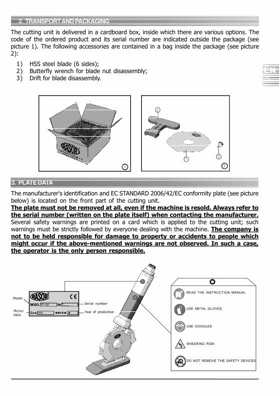
The manufacturer's identification and EC STANDARD 2006/42/EC conformity plate (see picturebelow) is located on the front part of the cutting unit.The plate must not be removed at all, even if the machine is resold. Always refer tothe serial number (written on the plate itself) when contacting the manufacturer.Several safety warnings are printed on a card which is applied to the cutting unit; suchwarnings must be strictly followed by everyone dealing with the machine. The company isnot to be held responsible for damage to property or accidents to people whichmight occur if the above-mentioned warnings are not observed. In such a case,the operator is the only person responsible.
1
Serial number
Year of production
Model
Mo to rdata
READ THE INSTRUCTION MANUAL
USE METAL GLOVES
USE GOGGLES
SHEARING RISK
DO NOT REMOVE THE SAFETY DEVICES
FP 100
900
2
31
P___________
The cutting unit is delivered in a cardboard box, inside which there are various options. Thecode of the ordered product and its serial number are indicated outside the package (seepicture 1). The following accessories are contained in a bag inside the package (see picture2):
1) HSS steel blade (6 sides);2) Butterfly wrench for blade nut disassembly;3) Drift for blade disassembly.
3. PLATE DATA
6EN
4. PRODUCT DESCRIPTION
1
32
4
5
6
8
7
10
11
12
13
14
9
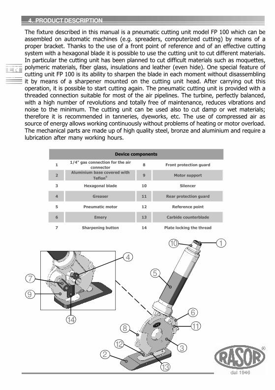
The fixture described in this manual is a pneumatic cutting unit model FP 100 which can beassembled on automatic machines (e.g. spreaders, computerized cutting) by means of aproper bracket. Thanks to the use of a front point of reference and of an effective cuttingsystem with a hexagonal blade it is possible to use the cutting unit to cut different materials.In particular the cutting unit has been planned to cut difficult materials such as moquettes,polymeric materials, fiber glass, insulations and leather (even hide). One special feature ofcutting unit FP 100 is its ability to sharpen the blade in each moment without disassemblingit by means of a sharpener mounted on the cutting unit head. After carrying out thisoperation, it is possible to start cutting again. The pneumatic cutting unit is provided with athreaded connection suitable for most of the air pipelines. The turbine, perfectly balanced,with a high number of revolutions and totally free of maintenance, reduces vibrations andnoise to the minimum. The cutting unit can be used also to cut damp or wet materials;therefore it is recommended in tanneries, dyeworks, etc. The use of compressed air assource of energy allows working continuously without problems of heating or motor overload.The mechanical parts are made up of high quality steel, bronze and aluminium and require alubrication after many working hours.
11/4" gas connection for the air
connector8 Front protection guard
2Aluminium base covered with
Teflon®®9 Motor support
3 Hexagonal blade 10 Silencer
4 Greaser 11 Rear protection guard
5 Pneumatic motor 12 Reference point
6 Emery 13 Carbide counterblade
7 Sharpening button 14 Plate locking the thread
Device components
EN7
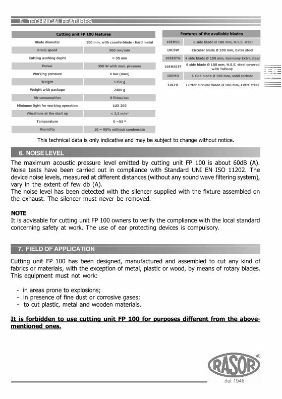
Cutting unit FP 100 has been designed, manufactured and assembled to cut any kind offabrics or materials, with the exception of metal, plastic or wood, by means of rotary blades.This equipment must not work:
- in areas prone to explosions; - in presence of fine dust or corrosive gases; - to cut plastic, metal and wooden materials.
It is forbidden to use cutting unit FP 100 for purposes different from the above-mentioned ones.
6. NOISE LEVEL
5. TECHNICAL FEATURES
This technical data is only indicative and may be subject to change without notice.
The maximum acoustic pressure level emitted by cutting unit FP 100 is about 60dB (A).Noise tests have been carried out in compliance with Standard UNI EN ISO 11202. Thedevice noise levels, measured at different distances (without any sound wave filtering system),vary in the extent of few db (A).The noise level has been detected with the silencer supplied with the fixture assembled onthe exhaust. The silencer must never be removed.
NOTEIt is advisable for cutting unit FP 100 owners to verify the compliance with the local standardconcerning safety at work. The use of ear protecting devices is compulsory.
6 side blade Ø 100 mm, H.S.S. steel
Circular blade Ø 100 mm, Extra steel
4 side blade Ø 100 mm, Germany Extra steel
6 side blade Ø 100 mm, H.S.S. steel covered with Teflon®®
6 side blade Ø 100 mm, solid carbide
Cutter circular blade Ø 100 mm, Extra steel
Features of the available blades
10EHSS
10SEXTG
10CFR
10EMD
10EHSSTF
10CSW
7. FIELD OF APPLICATION
100 mm, with counterblade - hard metal
900 rev/min
≈ 35 mm
350 W with max. pressure
6 bar (max)
1350 g
2400 g
9 litres/sec
LUX 200
< 2,5 m/s²
0 ~55 º
10 ~ 95% without condensate
Cutting working depht
Power
Weight
Cutting unit FP 100 features
Blade diameter
Blade speed
Working pressure
Temperature
Humidity
Weight with package
Air consumption
Minimum light for working operation
Vibrations at the start up
8EN
9. RESIDUAL RISKS
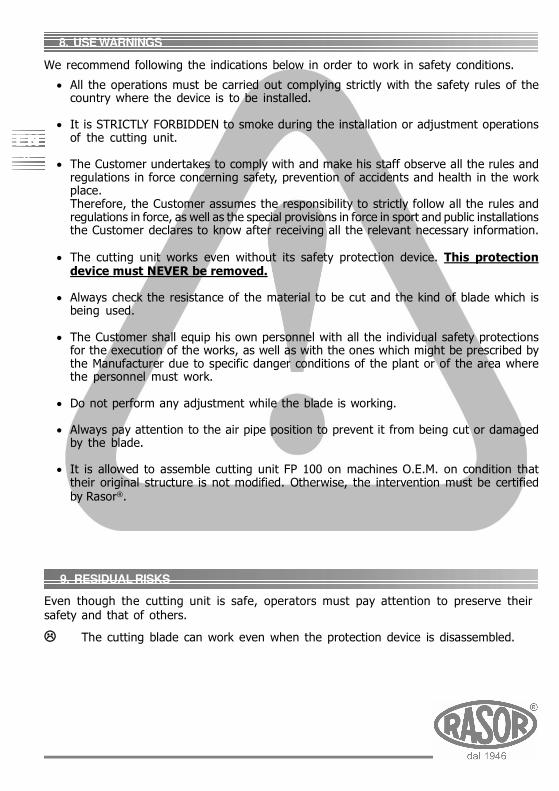
8. USE WARNINGS
We recommend following the indications below in order to work in safety conditions.
• All the operations must be carried out complying strictly with the safety rules of thecountry where the device is to be installed.
• It is STRICTLY FORBIDDEN to smoke during the installation or adjustment operationsof the cutting unit.
• The Customer undertakes to comply with and make his staff observe all the rules andregulations in force concerning safety, prevention of accidents and health in the workplace.Therefore, the Customer assumes the responsibility to strictly follow all the rules andregulations in force, as well as the special provisions in force in sport and public installationsthe Customer declares to know after receiving all the relevant necessary information.
• The cutting unit works even without its safety protection device. This protectiondevice must NEVER be removed.
• Always check the resistance of the material to be cut and the kind of blade which isbeing used.
• The Customer shall equip his own personnel with all the individual safety protectionsfor the execution of the works, as well as with the ones which might be prescribed bythe Manufacturer due to specific danger conditions of the plant or of the area wherethe personnel must work.
• Do not perform any adjustment while the blade is working.
• Always pay attention to the air pipe position to prevent it from being cut or damagedby the blade.
• It is allowed to assemble cutting unit FP 100 on machines O.E.M. on condition thattheir original structure is not modified. Otherwise, the intervention must be certifiedby Rasor®.
Even though the cutting unit is safe, operators must pay attention to preserve theirsafety and that of others.
The cutting blade can work even when the protection device is disassembled.
EN9
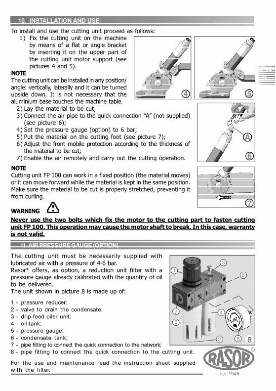
10. INSTALLATION AND USE
To install and use the cutting unit proceed as follows:1) Fix the cutting unit on the machine
by means of a flat or angle bracketby inserting it on the upper part ofthe cutting unit motor support (seepictures 4 and 5).
NOTEThe cutting unit can be installed in any position/angle: vertically, laterally and it can be turnedupside down. It is not necessary that thealuminium base touches the machine table.
2) Lay the material to be cut;3) Connect the air pipe to the quick connection “A” (not supplied)
(see picture 6);4) Set the pressure gauge (option) to 6 bar;5) Put the material on the cutting foot (see picture 7);6) Adjust the front mobile protection according to the thickness of
the material to be cut;7) Enable the air remotely and carry out the cutting operation.
NOTECutting unit FP 100 can work in a fixed position (the material moves)or it can move forward while the material is kept in the same position.Make sure the material to be cut is properly stretched, preventing itfrom curling.
4
Never use the two bolts which fix the motor to the cutting part to fasten cuttingunit FP 100. This operation may cause the motor shaft to break. In this case, warrantyis not valid.
5
6
7
A
11. AIR PRESSURE GAUGE (OPTION)
WARNING
The cutting unit must be necessarily supplied withlubricated air with a pressure of 4-6 bar.Rasor® offers, as option, a reduction unit filter with apressure gauge already calibrated with the quantity of oilto be delivered.The unit shown in picture 8 is made up of:
1 - pressure reducer;2 - valve to drain the condensate;3 - drip-feed oiler unit;4 - oil tank;5 - pressure gauge;6 - condensate tank;7 - pipe fitting to connect the quick connection to the network;8 - pipe fitt ing to connect the quick connection to the cutting unit.
For the use and maintenance read the instruct ion sheet suppliedwith the filter.
5
1
3
4
6
7
8
2 8
10EN
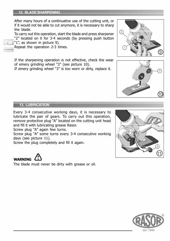
12. BLADE SHARPENING
13. LUBRICATION
Every 3-4 consecutive working days, it is necessary tolubricate the pair of gears. To carry out this operation,remove protective plug “A” located on the cutting unit headand fill it with lubricating grease Rasor.Screw plug “A” again few turns.Screw plug “A” some turns every 3-4 consecutive workingdays (see picture 11).Screw the plug completely and fill it again.
The blade must never be dirty with grease or oil.
11WARNING
2
9
A
10
1
3
After many hours of a continuative use of the cutting unit, orif it would not be able to cut anymore, it is necessary to sharpthe blade.To carry out this operation, start the blade and press sharpener“2” located on it for 3-4 seconds (by pressing push button“1”, as shown in picture 9).Repeat the operation 2-3 times.
If the sharpening operation is not effective, check the wearof emery grinding wheel “3” (see picture 10).If emery grinding wheel “3” is too worn or dirty, replace it.
EN11
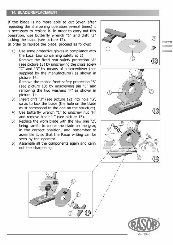
If the blade is no more able to cut (even afterrepeating the sharpening operation several times) itis necessary to replace it. In order to carry out thisoperation, use butterfly wrench “1” and drift “3”locking the blade (see picture 12).In order to replace the blade, proceed as follows:
1) Use some protective gloves in compliance withthe Local Law concerning safety at 2)Remove the fixed rear safety protection “A”(see picture 13) by unscrewing the cross screw“C” and “D” by means of a screwdriver (notsupplied by the manufacturer) as shown inpicture 14.Remove the mobile front safety protection “B”(see picture 13) by unscrewing pin “E” andremoving the two washers “F” as shown inpicture 14.
3) Insert drift “3” (see picture 12) into hole “G”,so as to lock the blade (the hole on the blademust correspond to the one on the structure).
4) Use butterfly wrench “1” to unscrew nut “H”and remove blade “L” (see picture 15).
5) Replace the worn blade with the new one “2”,being careful to center the blade on the gear,in the correct position, and remember toassemble it, so that the Rasor writing can beseen by the operator.
6) Assemble all the components again and carryout the sharpening.
14. BLADE REPLACEMENT
1
212
C
E
B A
D
F
13
14
L
1
H
15
G
3
12EN
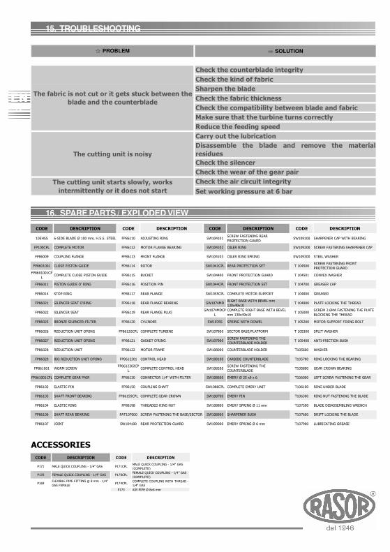
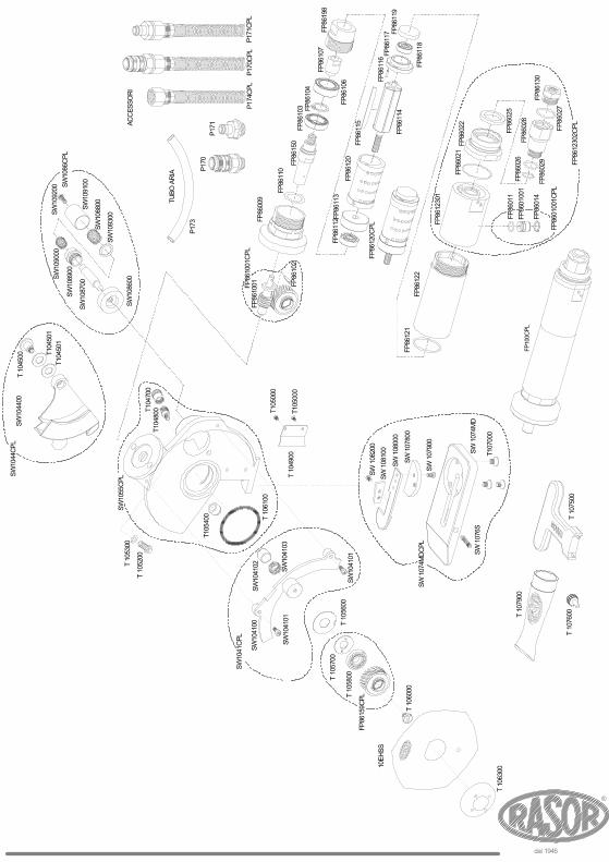
16. SPARE PARTS / EXPLODED VIEW
15. TROUBLESHOOTING
ACCESSORIESCODE DESCRIPTION CODE DESCRIPTION
P171 MALE QUICK COUPLING - 1/4" GAS P171CPLMALE QUICK COUPLING - 1/4" GAS (COMPLETE)
P170 FEMALE QUICK COUPLING - 1/4" GAS P170CPLFEMALE QUICK COUPLING - 1/4" GAS (COMPLETE)
P169FLEXIBLE PIPE FITTING Ø 8 mm - 1/4" GAS FEMALE
P174CPLCOMPLETE COUPLING WITH THREAD - 1/4" GAS
P173 AIR PIPE Ø 8x6 mm
SOLUTION
Check the counterblade integrityCheck the kind of fabricSharpen the bladeCheck the fabric thicknessCheck the compatibility between blade and fabricMake sure that the turbine turns correctlyReduce the feeding speedCarry out the lubricationDisassemble the blade and remove the materialresiduesCheck the silencerCheck the wear of the gear pairCheck the air circuit integritySet working pressure at 6 bar
The cutting unit starts slowly, works intermittently or it does not start
PROBLEM
The cutting unit is noisy
The fabric is not cut or it gets stuck between the blade and the counterblade
CODE DESCRIPTION CODE DESCRIPTION CODE DESCRIPTION CODE DESCRIPTION
10EHSS 6-SIDE BLADE Ø 100 mm, H.S.S. STEEL FP86110 ADJUSTING RING SW104101SCREW FASTENING REAR PROTECTION GUARD
SW109100 SHARPENER CAP WITH BEARING
FP100CPL COMPLETE MOTOR FP86112 MOTOR FLANGE BEARING SW104102 OILER RING SW109200 SCREW FASTENING SHARPENER CAP
FP86009 COUPLING FLANGE FP86113 FRONT FLANGE SW104103 OILER RING SPRING SW109300 STEEL WASHER
FP8601001 CLOSE PISTON GUIDE FP86114 ROTOR SW1041CPL REAR PROTECTION SET T 104500SCREW FASTENING FRONT PROTECTION GUARD
FP8601001CPL
COMPLETE CLOSE PISTON GUIDE FP86115 BUCKET SW104400 FRONT PROTECTION GUARD T 104501 CONVEX WASHER
FP86011 PISTON GUIDE O' RING FP86116 POSITION PIN SW1044CPL FRONT PROTECTION SET T 104700 GREASER CAP
FP86014 STOP RING FP86117 REAR FLANGE SW1055CPL COMPLETE MOTOR SUPPORT T 104800 GREASER
FP86021 SILENCER SEAT O'RING FP86118 REAR FLANGE BEARING SW1074MDRIGHT BASE WITH BEVEL mm 130x49x10
T 104900 PLATE LOCKING THE THREAD
FP86022 SILENCER SEAT FP86119 REAR FLANGE PLUGSW1074MDCP
LCOMPLETE RIGHT BASE WITH BEVEL mm 130x49x10
T 105000SCREW 2.6MA FASTENING THE PLATE BLOCKING THE THREAD
FP86025 BRONZE SILENCER-FILTER FP86120 CYLINDER SW1076S SPRING WITH DOWEL T 105200 MOTOR SUPPORT FIXING BOLT
FP86026 REDUCTION UNIT O'RING FP86120CPL COMPLETE TURBINE SW107800 SECTOR BASE/PLATFORM T 105300 SPLIT WASHER
FP86027 REDUCTION UNIT O'RING FP86121 GASKET O'RING SW107900SCREW FASTENING THE COUNTERBLADE HOLDER
T 105400 ANTI-FRICTION BUSH
FP86028 REDUCTION UNIT FP86122 MOTOR FRAME SW108000 COUNTERBLADE HOLDER T105600 WASHER
FP86029 BIG REDUCTION UNIT O'RING FP8612301 CONTROL HEAD SW108100 CARBIDE COUNTERBLADE T105700 RING LOCKING THE BEARING
FP861001 WORM SCREWFP8612302CP
LCOMPLETE CONTROL HEAD SW108200
SCREW FASTENING THE COUNTERBLADE
T105800 GEAR CROWN BEARING
FP861001CPL COMPLETE GEAR PAIR FP86130 CONNECTOR 1/4" WITH FILTER SW108600 EMERY Ø 25 x9 x 6 T106000 LEFT SCREW FASTENING THE GEAR
FP86102 ELASTIC PIN FP86150 COUPLING SHAFT SW1086CPL COMPLETE EMERY UNIT T106100 RING UNDER BLADE
FP86103 SHAFT FRONT BEARING FP86159CPL COMPLETE GEAR CROWN SW108700 EMERY PIN T106300 RING NUT FASTENING THE BLADE
FP86104 ELASTIC RING FP86198 THREADED RING NUT SW108800 EMERY SPRING Ø 11 mm T107500 BLADE DISASSEMBLING WRENCH
FP86106 SHAFT REAR BEARING PAT107000 SCREW FASTENING THE BASE/SECTOR SW108900 SHARPENER BUSH T107600 DRIFT LOCKING THE BLADE
FP86107 JOINT SW104100 REAR PROTECTION GUARD SW109000 EMERY SPRING Ø 6 mm T107900 LUBRICATING GREASE

WARRANTYRasor® Elettromeccanica S.r.l. cutting unit has a 12 month warranty from the date indicated
on the last page of this manual, except in case of different written agreements.The warranty covers all manufacturing and material defects. Replacement and repair operationsare covered only if carried out by our company and at our workshop.In case of returned goods for repair under warranty, the Customer must always send toRasor® the complete machine. Repairs under warranty of single faulty componentsare not accepted.The material to be repaired must be sent CARRIAGE FREE.Once the machine has been repaired, it will be sent CARRIAGE FORWARD to the customer.The warranty covers neither technicians' intervention on site nor the machine disassemblyfrom the installation place.If for practical reasons, one of our technicians is sent to the premises, the customer will becharged the costs plus the travelling expenses.
The warranty does not include:
failure caused by wrong use or assembly,
failure caused by external agents,
failure caused by lack of maintenance or neglicence;
blades and parts subject to wear.
WARRANTY FORFEITURE:
In case of arrearage or other breaches of contract,
Whenever changes or repairs are carried out on our cutting units without our prior
authorization,
Whenever the serial number is tampered with or cancelled,
Whenever the damage is caused by improper use, bad treatment, bumps, falls and
other causes not due to normal working conditions,
Whenever the unit seems tampered with, dismantled or previously repaired by
unauthorized staff,
In case the cutting units are used for purposes that are different from the ones
described in this manual.
All repair operations carried out under warranty do not interrupt its duration.
All disputes will be settled in the court of justice of Milan (Italy).We thank you in advance for the attention you will pay to this manual and we invite you toinform us of any change you deem necessary to improve it and make it more complete.
RASOR ELETTROMECCANICA SRLVia Vincenzo Caldesi 6 20161 Milan ∙ Italyph. +39 02 66 22 12 31 fax +39 02 66 22 12 [email protected]
www.rasor-cutters.com
FOLLOW US: