Embed Size (px)
Citation preview
FPGA-BASED MOTION CONTROLLER FOR WAFER-HANDLING ROBOT
Hsin-Hung Chou1, Ying-Shieh Kung2, Tai-Wei Tsui2 and Stone Cheng11Department of Mechanical Engineering, National Chiao-Tung University, HsinChu City, Taiwan
2Department of Electrical Engineering, Southern Taiwan University, Tainan City, TaiwanE-mail: [email protected]; [email protected]; [email protected]
ICETI 2012-B17004_SCINo. 13-CSME-30, E.I.C. Accession 3488
ABSTRACTThis study applies FPGA (Field Programmable Gate Arrays) technology to implement a motion controllerfor wafer-handling robot which has three-DOF (Degree of Freedom) motion. The proposed FPGA-basedmotion controller has two modules. The first module is Nios II processor which is used to realize the motiontrajectory computation and the three-axis position/speed controllers. The second module is demonstrated toimplement the three-axis current vector controllers by using FPGA hardware, and VHDL (VHSIC HardwareDescription Language) is adopted to describe the controller behavior. Therefore, a fully digital motioncontroller for wafer-handling robot, such as one trajectory planning, three current vector controllers andthree position/speed controllers are all implemented with an FPGA chip.
Keywords: wafer-handling robot; field programmable gate arrays (FPGA); motion controller.
CONTRÔLEUR DE MOUVEMENT BASÉ SUR LE RÉSEAU DE PORTES PROGRAMMABLES(FPGA) POUR ROBOT MANIPULATEUR DE PLAQUETTES
RÉSUMÉLa technologie de réseau de portes programmables (FPGA) pour implanter un système de contrôle de mou-vement pour un robot manipulateur de plaquettes, à trois degrés de liberté de mouvement, est le sujet denotre recherche. Le contrôleur de mouvement proposé, basé sur le réseau de portes programmables (FPGA),est en deux modules. Le premier, le processeur NIOS II, est utilisé pour réaliser le calcul de la trajectoiredu mouvement et les contrôleurs à trois axes position/vitesse. Le second module fait la démonstration del’implantation du contrôle de courant vectoriel par l’utilisation du réseau de portes programmables (FPGA),et le langage descriptif de matériel à circuits intégrés à très grande vitesse, (VHDL) est adopté pour décrirele comportement du contrôleur. Par conséquent, un contrôleur de mouvement totalement digital pour unrobot manipulateur de plaquettes, tel qu’un plan de trajectoire, trois contrôleurs de courant vectoriel, et troiscontrôleurs de position/vitesse sont tous implantés avec une puce FPGA.
Mots-clés : robot manipulateur de plaquettes ; réseau de portes programmables (FPGA) ; contrôleur demouvement.
427Transactions of the Canadian Society for Mechanical Engineering, Vol. 37, No. 3, 2013
1. INTRODUCTION
Due to the rapid development of IC manufacturing, the automated wafer-handling system has become theimportant technologies of IC equipments [1]. Especially, the automated wafer-handling robots play a pri-mary role in this system, which execute the tasks of exact location and handling wafers among the differentworking procedures with rapidly and smoothly transfer [2, 3]. To increase the performance and the produc-tivity of the wafer-handling robot, controller architecture and controller algorithm are currently an excitingand highly challenging research focus. However, as for robots control, several solutions for implementingthe control architecture have been proposed [3–5, 9–11]. PC-based or processor-based controller is adoptedas the control architecture for early years. For example, Cong et al. [3] used PC-based microcontroller for awafer-handling robot. Kabuka et al. [4] applied two high-performance floating-point signal processors anda set of dedicated motion controllers to build a control system for a six-joint robots arm. Yasuda [5] adopteda PC-based microcomputer and several PIC microcomputers to construct a distributed motion controller formobile robots. In recent years, due to the advantages of the programmable hard-wired feature, fast time-to-market, shorter design cycle, embedding processor, low power consumption and higher density, FPGAhave been widely investigated for implementing digital system. Hence, many practical applications in mo-tor control [6–8] and multi-axis robot control and platform [9–12] have been studied. In addition, the novelFPGA technology is able to combine an embedded processor IP (Intellectual Property) and an applicationIP to be an SoPC (System-on-a-Programmable-Chip) developing environment, allowing a user to designan SoPC module by mixing hardware and software [13, 14]. As a result, the software/hardware co-designincreases the programmable, flexibility of the designed digital system and reduces the development time.Additionally, software/hardware parallel processing enhances the controller performance.
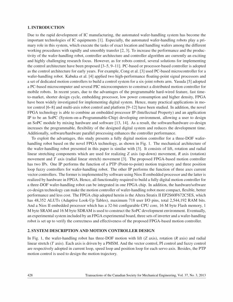
To exploit the advantages, this study presents a fully digital motion controller for a three-DOF wafer-handling robot based on the novel FPGA technology, as shown in Fig. 1. The mechanical architecture ofthe wafer-handling robot presented in this paper is similar with [3]. It consists of lift, rotation and radiallinear stretching components which are used for realizing Z axis (up-down) movement, R axis (rotation)movement and T axis (radial linear stretch) movement [3]. The proposed FPGA-based motion controllerhas two IPs. One IP performs the function of a PTP (Point-to-point) motion trajectory and three positionloop fuzzy controllers for wafer-handling robot. The other IP performs the function of three axes currentvector controllers. The former is implemented by software using Nios II embedded processor and the latter isrealized by hardware in FPGA. Hence, all functionality required to build a fully digital motion controller fora three-DOF wafer-handling robot can be integrated in one FPGA chip. In addition, the hardware/softwareco-design technology can make the motion controller of wafer-handling robot more compact, flexible, betterperformance and less cost. The FPGA chip adopted herein is the Altera Stratix II EP2S60F672C5ES, whichhas 48,352 ALUTs (Adaptive Look-Up Tables), maximum 718 user I/O pins, total 2,544,192 RAM bits.And a Nios II embedded processor which has a 32-bit configurable CPU core, 16 M byte Flash memory, 1M byte SRAM and 16 M byte SDRAM is used to construct the SoPC development environment. Eventually,an experimental system included by an FPGA experimental board, three sets of inverter and a wafer-handlingrobot is set up to verify the correctness and effectiveness of the proposed FPGA-based motion controller.
2. SYSTEM DESCRIPTION AND MOTION CONTROLLER DESIGN
In Fig. 1, the wafer-handling robot has three-DOF motion with lift (Z axis), rotation (R axis) and radiallinear stretch (T axis). Each axis is driven by a PMSM. And the vector control, PI control and fuzzy controlare respectively adopted in current loop, speed loop and position loop for each servo axis. Besides, the PTPmotion control is used to design the motion trajectory.
428 Transactions of the Canadian Society for Mechanical Engineering, Vol. 37, No. 3, 2013
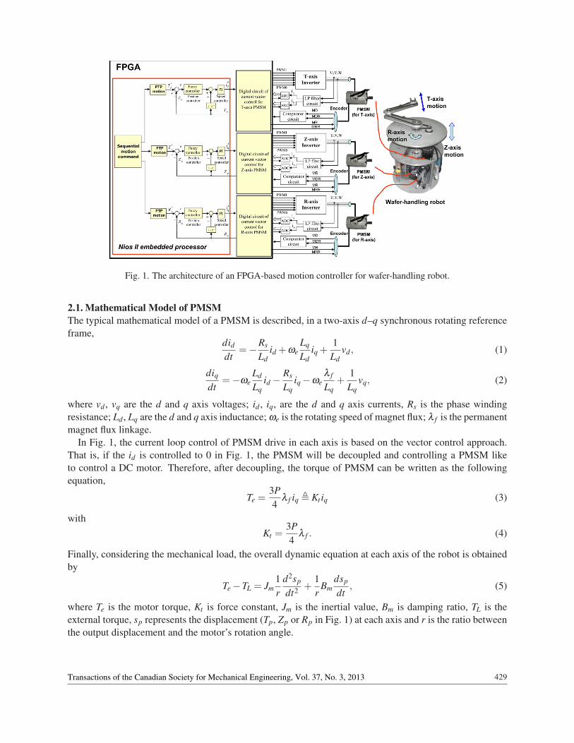
Fig. 1. The architecture of an FPGA-based motion controller for wafer-handling robot.
2.1. Mathematical Model of PMSMThe typical mathematical model of a PMSM is described, in a two-axis d–q synchronous rotating referenceframe,
diddt
=−Rs
Ldid +ωe
Lq
Ldiq +
1Ld
vd , (1)
diqdt
=−ωeLd
Lqid−
Rs
Lqiq−ωe
λ f
Lq+
1Lq
vq, (2)
where vd , vq are the d and q axis voltages; id , iq, are the d and q axis currents, Rs is the phase windingresistance; Ld , Lq are the d and q axis inductance; ωe is the rotating speed of magnet flux; λ f is the permanentmagnet flux linkage.
In Fig. 1, the current loop control of PMSM drive in each axis is based on the vector control approach.That is, if the id is controlled to 0 in Fig. 1, the PMSM will be decoupled and controlling a PMSM liketo control a DC motor. Therefore, after decoupling, the torque of PMSM can be written as the followingequation,
Te =3P4
λ f iq , Kt iq (3)
withKt =
3P4
λ f . (4)
Finally, considering the mechanical load, the overall dynamic equation at each axis of the robot is obtainedby
Te−TL = Jm1r
d2sp
dt2 +1r
Bmdsp
dt, (5)
where Te is the motor torque, Kt is force constant, Jm is the inertial value, Bm is damping ratio, TL is theexternal torque, sp represents the displacement (Tp, Zp or Rp in Fig. 1) at each axis and r is the ratio betweenthe output displacement and the motor’s rotation angle.
429Transactions of the Canadian Society for Mechanical Engineering, Vol. 37, No. 3, 2013
2.2. Fuzzy Controller (FC)In Fig. 1, the position controller in each axis of wafer-handling robot adopts fuzzy controller, which includesfuzzification, fuzzy rules, inference mechanism and defuzzification. Herein, an FC design is presented. Atfirst, the position error and its error change, e, de, are defined by
e(k) = s∗p(k)− sp(k), (6)
de(k) = e(k)− e(k−1). (7)
The Ker and Kder are the gains of the input variables e and de, respectively, and u f is the output variable ofthe FC. The design procedure of the FC is as follows:
(a) Take the E and dE as the input linguist variables, which are defined by {A0,A1,A2,A3,A4,A5,A6} and{B0,B1,B2,B3,B4,B5,B6}, respectively. Each linguist value of E and dE are based on the symmetricaltriangular membership function. The symmetrical triangular membership function are determineduniquely by three real numbers ξ1 ≤ ξ2 ≤ ξ3, if one fixes f (ξ1) = f (ξ3) = 0 and f (ξ2) = 1.
(b) Compute the membership degree of e and de. Figure 2 shows that the only two linguistic values areexcited and gave a non-zero membership in any input value, and the membership degree µAi(e) canbe derived, in which the error e is located between ei and ei+1, two linguist values of Ai and Ai+1 areexcited, and the membership degree is obtained by
µAi(e) =ei+1− e
2and µAi+1(e) = 1−µAi(e), (8)
where ei+1 , −6+ 2 ∗ (i+ 1). Similar results can be obtained in computing the membership degreeµB j(de).
(c) Select the initial fuzzy control rules, such as
IF e is Ai and ∆e is B j THEN u f is c j,i, (9)
where i and j = 0∼ 6, Ai and B j are fuzzy number, and c j,i is real number.
(d) Construct the fuzzy system u f (e,de) by using the singleton fuzzifier, product-inference rule, andcentral average defuzzifier method. For example, if the error e is located between ei and ei+1, andthe error change de is located between de j and de j+1, only four linguistic values Ai, Ai+1, B j, B j+1and corresponding consequent values c j,i, c j+1,i, c j,i+1, c j+1,i+1 can be excited, and Eq. (9) can bereplaced by the following expression:
u f (e,de) =∑
i+1n=i ∑
j+1m= j cm,n[µAn(e)∗µBm(de)]
∑i+1n=i ∑
j+1m= j µAn(e)∗µBm(de)
,i+1
∑n=i
j+1
∑m= j
cm,n ∗dn,m, (10)
where dn,m , µAn(e)∗µBm(de). And those cm,n denote the value of the singleton fuzzier.
430 Transactions of the Canadian Society for Mechanical Engineering, Vol. 37, No. 3, 2013
Fig. 2. Membership function, fuzzy rule, fuzzy inference and defuzzification.
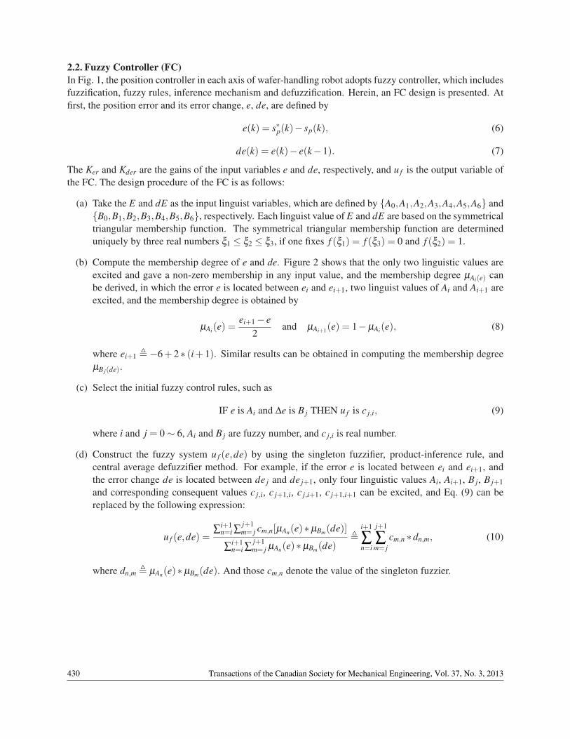
Fig. 3. Main arm of the wafer-handling robot.
2.3. Motion Analysis of the Main ArmThe main arm of the wafer-handling robot used in this study is shown in Fig. 3 which is a four-bar linkagemechanism consisted of gear trains, belts, links and a fork. Figure 4 show the whole motion process of themain arm in real system. The link I at main arm is indirectly driven by a PMSM. Then, it will drive the linkII and fork through transmission of gear train and belts. By appropriate design in gear ratio of link I andlink II with 2:1 and 1:2, respectively, the fork at the end of the main arm can keep in a fixed straight pathduring the whole motion process, as shown in Fig. 4. Therefore, a rotation motion in PMSM will transfer toa straight back-and-forth motion for the fork of the main arm.
Since the sensors are difficult to install at the tip of the main arm to measure the fork position, the way toobtain the fork displacement can only be indirectly computed by the rotation angle of the PMSM. Figure 3bshows the kinematic diagram of the main arm and its kinematic analysis is as follows. First, the input of themain arm is the rotation angle of the PMSM and the output is the fork’s displacement. Again, the length oflink I and link II is l and the gear ratio between at the gear of PMSM and at the gear of the link I is 1 : ra.Then, from Fig. 3b, the forward kinematic equation of the main arm can be formulated by
Tp = 2× l× cos(θl) (11)
andθl = θm/ra (12)
where θm is the rotation angle of PMSM, θl is the rotation angle at link I and Tp is the displacement of thefork. In our experimental system, the l is designed with 250 mm and ra is chosen by 20; therefore, if PMSMrotates five cycles, the motion in link I is rotated between 0 and 90◦ and the stroke of the straight motion in
431Transactions of the Canadian Society for Mechanical Engineering, Vol. 37, No. 3, 2013
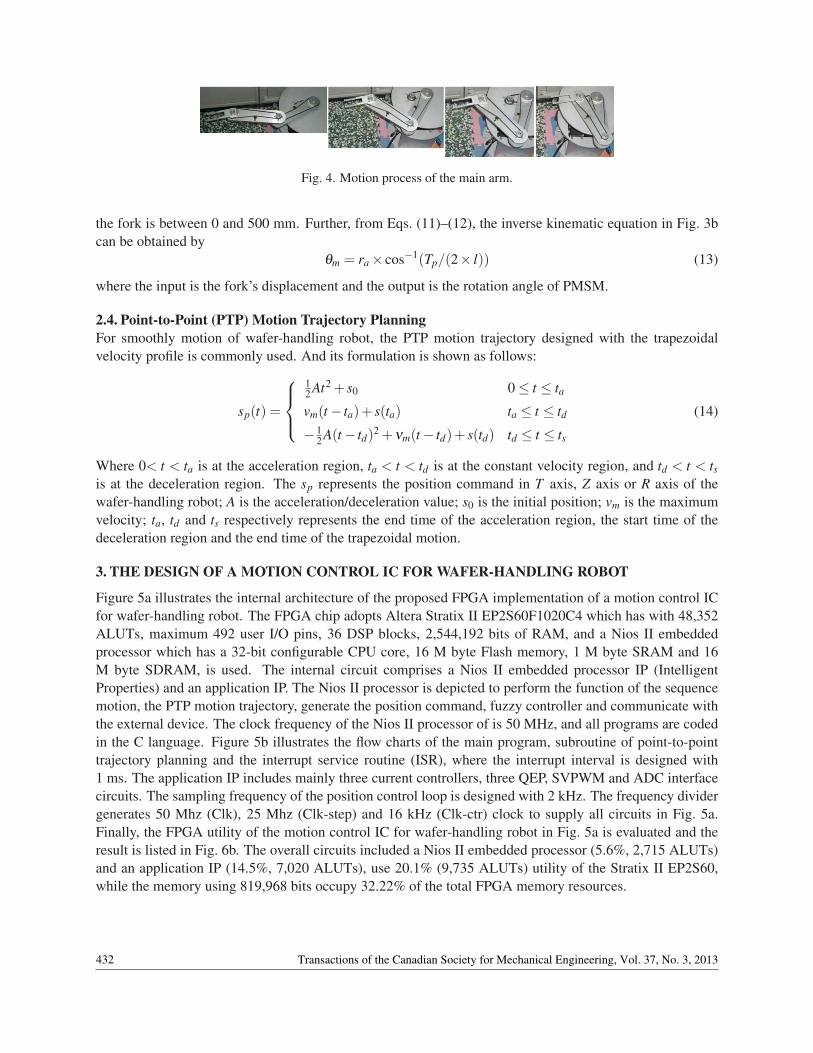
Fig. 4. Motion process of the main arm.
the fork is between 0 and 500 mm. Further, from Eqs. (11)–(12), the inverse kinematic equation in Fig. 3bcan be obtained by
θm = ra× cos−1(Tp/(2× l)) (13)
where the input is the fork’s displacement and the output is the rotation angle of PMSM.
2.4. Point-to-Point (PTP) Motion Trajectory PlanningFor smoothly motion of wafer-handling robot, the PTP motion trajectory designed with the trapezoidalvelocity profile is commonly used. And its formulation is shown as follows:
sp(t) =
12 At2 + s0 0≤ t ≤ tavm(t− ta)+ s(ta) ta ≤ t ≤ td−1
2 A(t− td)2 +νm(t− td)+ s(td) td ≤ t ≤ ts
(14)
Where 0< t < ta is at the acceleration region, ta < t < td is at the constant velocity region, and td < t < tsis at the deceleration region. The sp represents the position command in T axis, Z axis or R axis of thewafer-handling robot; A is the acceleration/deceleration value; s0 is the initial position; vm is the maximumvelocity; ta, td and ts respectively represents the end time of the acceleration region, the start time of thedeceleration region and the end time of the trapezoidal motion.
3. THE DESIGN OF A MOTION CONTROL IC FOR WAFER-HANDLING ROBOT
Figure 5a illustrates the internal architecture of the proposed FPGA implementation of a motion control ICfor wafer-handling robot. The FPGA chip adopts Altera Stratix II EP2S60F1020C4 which has with 48,352ALUTs, maximum 492 user I/O pins, 36 DSP blocks, 2,544,192 bits of RAM, and a Nios II embeddedprocessor which has a 32-bit configurable CPU core, 16 M byte Flash memory, 1 M byte SRAM and 16M byte SDRAM, is used. The internal circuit comprises a Nios II embedded processor IP (IntelligentProperties) and an application IP. The Nios II processor is depicted to perform the function of the sequencemotion, the PTP motion trajectory, generate the position command, fuzzy controller and communicate withthe external device. The clock frequency of the Nios II processor of is 50 MHz, and all programs are codedin the C language. Figure 5b illustrates the flow charts of the main program, subroutine of point-to-pointtrajectory planning and the interrupt service routine (ISR), where the interrupt interval is designed with1 ms. The application IP includes mainly three current controllers, three QEP, SVPWM and ADC interfacecircuits. The sampling frequency of the position control loop is designed with 2 kHz. The frequency dividergenerates 50 Mhz (Clk), 25 Mhz (Clk-step) and 16 kHz (Clk-ctr) clock to supply all circuits in Fig. 5a.Finally, the FPGA utility of the motion control IC for wafer-handling robot in Fig. 5a is evaluated and theresult is listed in Fig. 6b. The overall circuits included a Nios II embedded processor (5.6%, 2,715 ALUTs)and an application IP (14.5%, 7,020 ALUTs), use 20.1% (9,735 ALUTs) utility of the Stratix II EP2S60,while the memory using 819,968 bits occupy 32.22% of the total FPGA memory resources.
432 Transactions of the Canadian Society for Mechanical Engineering, Vol. 37, No. 3, 2013
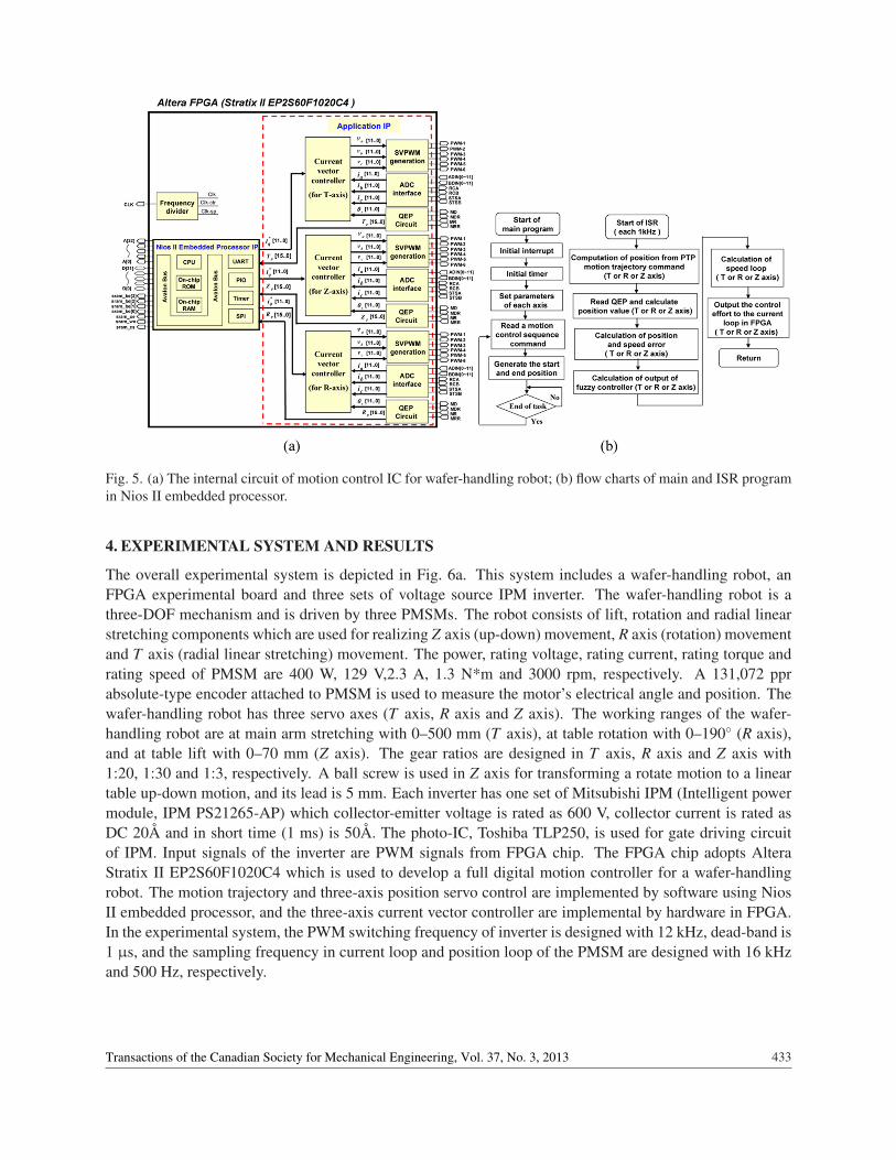
Fig. 5. (a) The internal circuit of motion control IC for wafer-handling robot; (b) flow charts of main and ISR programin Nios II embedded processor.
4. EXPERIMENTAL SYSTEM AND RESULTS
The overall experimental system is depicted in Fig. 6a. This system includes a wafer-handling robot, anFPGA experimental board and three sets of voltage source IPM inverter. The wafer-handling robot is athree-DOF mechanism and is driven by three PMSMs. The robot consists of lift, rotation and radial linearstretching components which are used for realizing Z axis (up-down) movement, R axis (rotation) movementand T axis (radial linear stretching) movement. The power, rating voltage, rating current, rating torque andrating speed of PMSM are 400 W, 129 V,2.3 A, 1.3 N*m and 3000 rpm, respectively. A 131,072 pprabsolute-type encoder attached to PMSM is used to measure the motor’s electrical angle and position. Thewafer-handling robot has three servo axes (T axis, R axis and Z axis). The working ranges of the wafer-handling robot are at main arm stretching with 0–500 mm (T axis), at table rotation with 0–190◦ (R axis),and at table lift with 0–70 mm (Z axis). The gear ratios are designed in T axis, R axis and Z axis with1:20, 1:30 and 1:3, respectively. A ball screw is used in Z axis for transforming a rotate motion to a lineartable up-down motion, and its lead is 5 mm. Each inverter has one set of Mitsubishi IPM (Intelligent powermodule, IPM PS21265-AP) which collector-emitter voltage is rated as 600 V, collector current is rated asDC 20Å and in short time (1 ms) is 50Å. The photo-IC, Toshiba TLP250, is used for gate driving circuitof IPM. Input signals of the inverter are PWM signals from FPGA chip. The FPGA chip adopts AlteraStratix II EP2S60F1020C4 which is used to develop a full digital motion controller for a wafer-handlingrobot. The motion trajectory and three-axis position servo control are implemented by software using NiosII embedded processor, and the three-axis current vector controller are implemental by hardware in FPGA.In the experimental system, the PWM switching frequency of inverter is designed with 12 kHz, dead-band is1 µs, and the sampling frequency in current loop and position loop of the PMSM are designed with 16 kHzand 500 Hz, respectively.
433Transactions of the Canadian Society for Mechanical Engineering, Vol. 37, No. 3, 2013
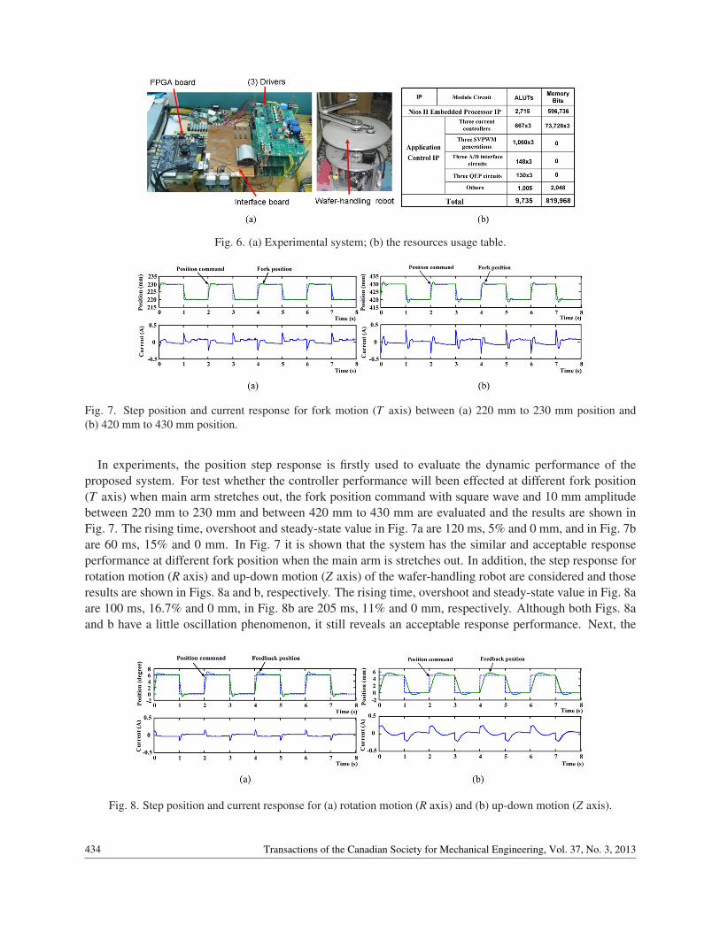
Fig. 6. (a) Experimental system; (b) the resources usage table.
Fig. 7. Step position and current response for fork motion (T axis) between (a) 220 mm to 230 mm position and(b) 420 mm to 430 mm position.
In experiments, the position step response is firstly used to evaluate the dynamic performance of theproposed system. For test whether the controller performance will been effected at different fork position(T axis) when main arm stretches out, the fork position command with square wave and 10 mm amplitudebetween 220 mm to 230 mm and between 420 mm to 430 mm are evaluated and the results are shown inFig. 7. The rising time, overshoot and steady-state value in Fig. 7a are 120 ms, 5% and 0 mm, and in Fig. 7bare 60 ms, 15% and 0 mm. In Fig. 7 it is shown that the system has the similar and acceptable responseperformance at different fork position when the main arm is stretches out. In addition, the step response forrotation motion (R axis) and up-down motion (Z axis) of the wafer-handling robot are considered and thoseresults are shown in Figs. 8a and b, respectively. The rising time, overshoot and steady-state value in Fig. 8aare 100 ms, 16.7% and 0 mm, in Fig. 8b are 205 ms, 11% and 0 mm, respectively. Although both Figs. 8aand b have a little oscillation phenomenon, it still reveals an acceptable response performance. Next, the
Fig. 8. Step position and current response for (a) rotation motion (R axis) and (b) up-down motion (Z axis).
434 Transactions of the Canadian Society for Mechanical Engineering, Vol. 37, No. 3, 2013
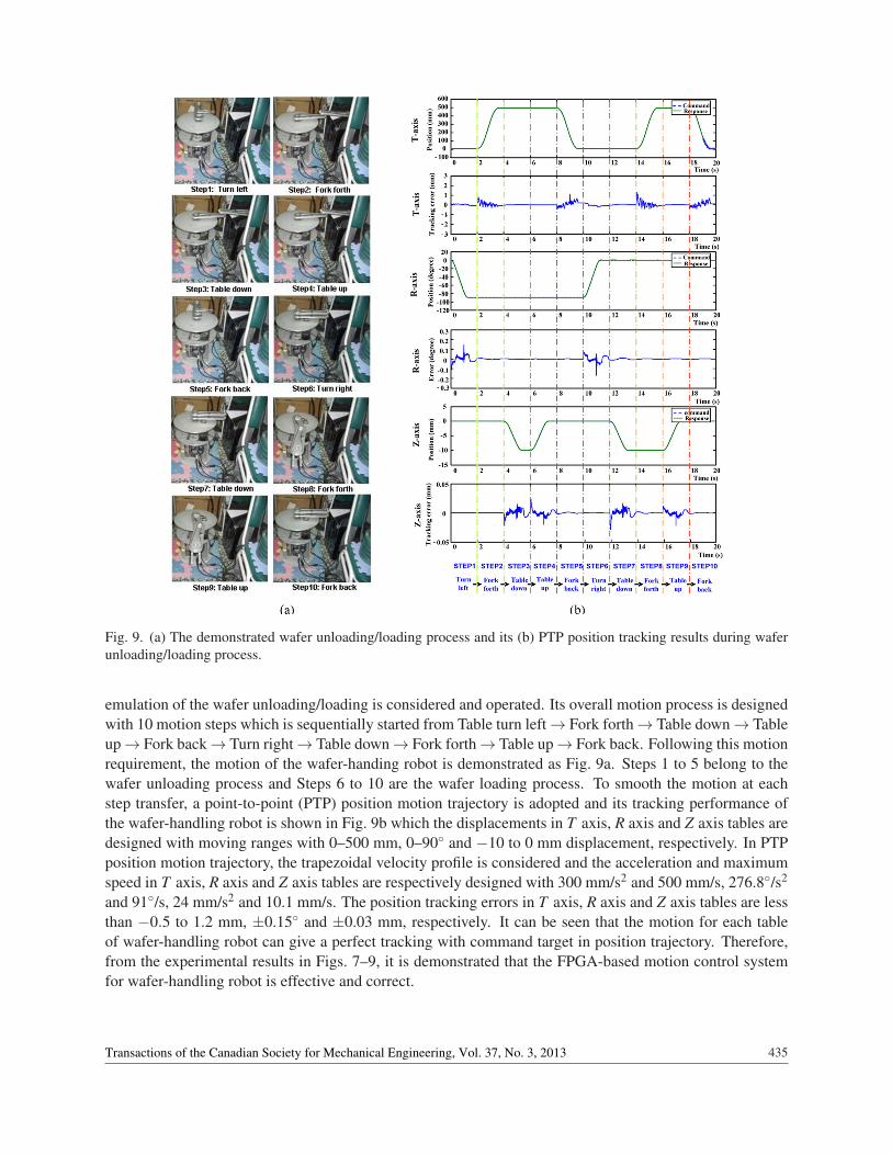
Fig. 9. (a) The demonstrated wafer unloading/loading process and its (b) PTP position tracking results during waferunloading/loading process.
emulation of the wafer unloading/loading is considered and operated. Its overall motion process is designedwith 10 motion steps which is sequentially started from Table turn left→ Fork forth→ Table down→ Tableup→ Fork back→ Turn right→ Table down→ Fork forth→ Table up→ Fork back. Following this motionrequirement, the motion of the wafer-handing robot is demonstrated as Fig. 9a. Steps 1 to 5 belong to thewafer unloading process and Steps 6 to 10 are the wafer loading process. To smooth the motion at eachstep transfer, a point-to-point (PTP) position motion trajectory is adopted and its tracking performance ofthe wafer-handling robot is shown in Fig. 9b which the displacements in T axis, R axis and Z axis tables aredesigned with moving ranges with 0–500 mm, 0–90◦ and −10 to 0 mm displacement, respectively. In PTPposition motion trajectory, the trapezoidal velocity profile is considered and the acceleration and maximumspeed in T axis, R axis and Z axis tables are respectively designed with 300 mm/s2 and 500 mm/s, 276.8◦/s2
and 91◦/s, 24 mm/s2 and 10.1 mm/s. The position tracking errors in T axis, R axis and Z axis tables are lessthan −0.5 to 1.2 mm, ±0.15◦ and ±0.03 mm, respectively. It can be seen that the motion for each tableof wafer-handling robot can give a perfect tracking with command target in position trajectory. Therefore,from the experimental results in Figs. 7–9, it is demonstrated that the FPGA-based motion control systemfor wafer-handling robot is effective and correct.
435Transactions of the Canadian Society for Mechanical Engineering, Vol. 37, No. 3, 2013
5. CONCLUSIONS
The realization of a motion control system for a wafer-handling robot based on the novel FPGA technologyis successfully demonstrated in this paper. The conclusions herein are summarized as follows:
(a) The functionalities required to build a fully digital motion controller of wafer-handling robot, suchas the PTP motion trajectory, three-axis position fuzzy controller, three-axis speed P controller andthree-axis current vector controller are all realized within one FPGA.
(b) The PTP motion trajectory scheme and three-axis position/speed controller are implemented in soft-ware by using Nios II embedded processor and three-axis current vector controller are implementedin hardware by FPGA. The software/hardware co-design technology with the parallel processing canmake the system performance increased.
However, the experimental results from step response and PTP motion tracking response have been revealedwell performance in the proposed FPGA-based motion controller for wafer-handling robot.
ACKNOWLEDGEMENT
This work was supported by National Science Council of the R.O.C. under grant no. NSC 100-2221-E-218-043.
REFERENCES
1. Kaempf, U., “Automated wafer transport in the wafer fab”, in Proceedings of the IEEE/SEM Advanced Semi-conductor Manufacturing Conference and Workshop, pp. 356–361, 1997.
2. Cong, M., Zhou, Y., Jiang, Y., Kang, R. and Guo, D., “An automated waferhandling system based on the inte-grated circuit equipments”, in Proceeding of the IEEE International Conference on Robotics and Biomimetics,pp. 240–245, 2005.
3. Cong, M., Yu, X., Shen, B. and Liu J., “Research on a novel R-θ wafer-handling robot”, in Proceedings of theIEEE International Conference on Automation and Logistics, pp. 597–602, 2007.
4. Kabuka, M., Glaskowsky, P. and Miranda, J., “Microcontroller-based architecture for control of a six joints robotarm”, IEEE Transactions on Industrial Electronics, Vol. 35, No. 2, pp. 217–221, 1988.
5. Yasuda, G., “Microcontroller implementation for distributed motion control of mobile robots”, in Proceedingsof International Workshop on Advanced Motion Control, pp. 114–119, 2000.
6. Monmasson, E., Idkhajine, L., Cirstea, M.N., Bahri, I., Tisan, A. and Naouar, M.W., “FPGAs in industrial controlapplications”, IEEE Transaction on Industrial Informatics, Vol. 7 No. 2, pp. 224–243, 2011.
7. Monmasson, E., Idkhajine, L. and Naouar, M.W., “FPGA-based controllers”, IEEE Industrial Electronics Mag-azine, Vol. 5, No. 1, pp. 14–26, 2011.
8. Kung, Y.S. and Tsai, M.H., “FPGA-based speed control IC for PMSM drive with adaptive fuzzy control”, IEEETransactions on Power Electronics, Vol. 22, No. 6, pp. 2476–2486, November 2007.
9. Shao, X. and Sun, D., “Development of a new robot controller architecture with FPGA-Based IC design forimproved high-speed performance”, IEEE Transactions on Industrial Electronics, Vol. 3, No. 4, pp. 312–321,November 2007.
10. Kung, Y.S., Tseng, K.H., Chen, C.S., Sze H.Z. and Wang, A.P., “FPGA-implementation of inverse kinematicsand servo controller for robot manipulator”, in Proceedings of the IEEE International Conference on Roboticsand Biomimetics, pp. 1163–1168, 2006.
11. Cho, J.U., Le, Q.N. and Jeon, J.W., “An FPGA-based multiple-axis motion control chip”, IEEE Transactions onIndustrial Electronics, Vol. 56, No. 3, pp. 856–370, March 2009.
436 Transactions of the Canadian Society for Mechanical Engineering, Vol. 37, No. 3, 2013
12. Itul, T. and Pisla, D., “On the kinematics and dynamics of 3-DOF parallel robots with triangle platform”, Journalof Vibroengineering, Vol. 11, Issue 1, pp. 188–200, March 2009.
13. Kung, Y.S., Fung, R.F. and Tai, T.Y., “Realization of a motion control IC for X-Y Table based on novel FPGAtechnology”, IEEE Transactions on Industrial Electronics, Vol. 56, No. 1, pp. 43–53, January 2009.
14. Wei, H., Wang S., Sun, K., Chen, Y. and Wang T., “Research of SoPC-based reconfigurable machine toolscontroller”, in Proceedings of International Conference on Industrial Informatics, pp. 117–122, 2008.
437Transactions of the Canadian Society for Mechanical Engineering, Vol. 37, No. 3, 2013