Embed Size (px)
Citation preview
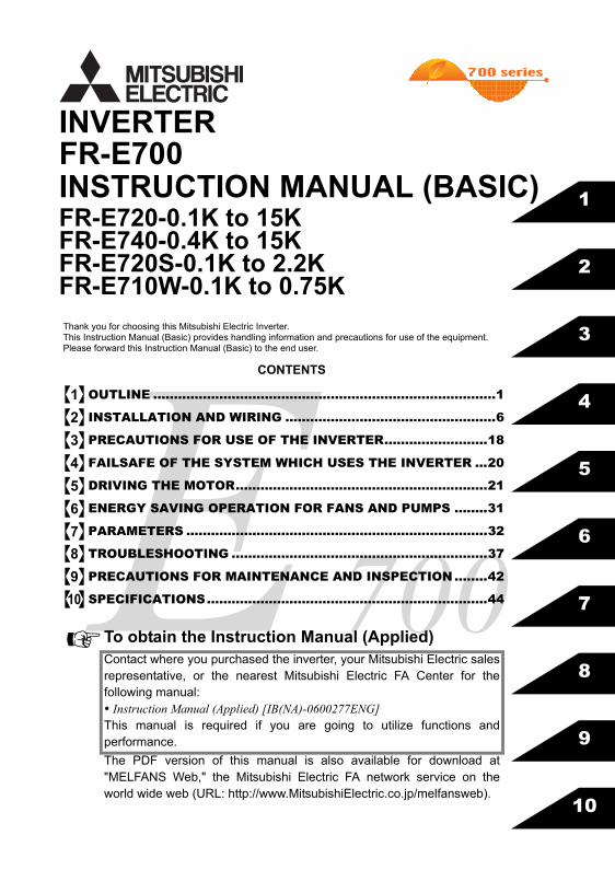
FR-E700INSTRUCTION MANUAL (BASIC)FR-E720-0.1K to 15KFR-E740-0.4K to 15KFR-E720S-0.1K to 2.2KFR-E710W-0.1K to 0.75K
INVERTER
7005
6
7
8
9
10
4
3
2
1
CONTENTS
OUTLINE ...................................................................................1
INSTALLATION AND WIRING ...................................................6
PRECAUTIONS FOR USE OF THE INVERTER.........................18
FAILSAFE OF THE SYSTEM WHICH USES THE INVERTER ...20
DRIVING THE MOTOR.............................................................21
ENERGY SAVING OPERATION FOR FANS AND PUMPS ........31
PARAMETERS .........................................................................32
TROUBLESHOOTING ..............................................................37
PRECAUTIONS FOR MAINTENANCE AND INSPECTION........42
SPECIFICATIONS....................................................................44
Thank you for choosing this Mitsubishi Electric Inverter.This Instruction Manual (Basic) provides handling information and precautions for use of the equipment.Please forward this Instruction Manual (Basic) to the end user.
To obtain the Instruction Manual (Applied)Contact where you purchased the inverter, your Mitsubishi Electric salesrepresentative, or the nearest Mitsubishi Electric FA Center for thefollowing manual: Instruction Manual (Applied) [IB(NA)-0600277ENG]This manual is required if you are going to utilize functions andperformance.
The PDF version of this manual is also available for download at"MELFANS Web," the Mitsubishi Electric FA network service on theworld wide web (URL: http://www.MitsubishiElectric.co.jp/melfansweb).
12345678910
This Instruction Manual (Basic) provides handling information and precautions for use of the equipment.Please forward this Instruction Manual (Basic) to the end user.
1. Electric Shock Prevention
2. Fire Prevention
3.Injury Prevention
4. Additional InstructionsAlso the following points must be noted to prevent anaccidental failure, injury, electric shock, etc.(1) Transportation and Mounting
This section is specifically about safety mattersDo not attempt to install, operate, maintain or inspect theinverter until you have read through the Instruction Manual(Basic) and appended documents carefully and can use theequipment correctly. Do not use this product until you havea full knowledge of the equipment, safety information andinstructions.In this Instruction Manual (Basic), the safety instructionlevels are classified into "WARNING" and "CAUTION".
Incorrect handling may cause hazardous conditions, resulting in death or severe injury.
Incorrect handling may cause hazardous conditions, resulting in medium or slight injury, or may cause only material damage.
The level may even lead to a seriousconsequence according to conditions. Both instructionlevels must be followed because these are important topersonal safety.
While power is ON or when the inverter is running, do notopen the front cover. Otherwise you may get an electricshock.Do not run the inverter with the front cover or wiring coverremoved. Otherwise you may access the exposed high-voltage terminals or the charging part of the circuitry andget an electric shock.Even if power is OFF, do not remove the front coverexcept for wiring or periodic inspection. You mayaccidentally touch the charged inverter circuits and get anelectric shock.Before wiring or inspection, power must be switched OFF.To confirm that, LED indication of the operation panelmust be checked. (It must be OFF.) Any person who isinvolved in wiring or inspection shall wait for at least 10minutes after the power supply has been switched OFFand check that there are no residual voltage using a testeror the like. The capacitor is charged with high voltage forsome time after power OFF, and it is dangerous.This inverter must be earthed (grounded). Earthing(grounding) must conform to the requirements of nationaland local safety regulations and electrical code (NEC section250, IEC 536 class 1 and other applicable standards).A neutral-point earthed (grounded) power supply for 400Vclass inverter in compliance with EN standard must be used.Any person who is involved in wiring or inspection of thisequipment shall be fully competent to do the work.The inverter must be installed before wiring. Otherwiseyou may get an electric shock or be injured.Setting dial and key operations must be performed withdry hands to prevent an electric shock.Do not subject the cables to scratches, excessive stress,heavy loads or pinching. Otherwise you may get anelectric shock.Do not change the cooling fan while power is ON. It isdangerous to change the cooling fan while power is ON.Do not touch the printed circuit board or handle thecables with wet hands. Otherwise you may get an electricshock. When measuring the main circuit capacitor capacity, theDC voltage is applied to the motor for 1s at powering OFF.Never touch the motor terminal, etc. right after poweringOFF to prevent an electric shock.
WARNING
CAUTION
CAUTION
WARNING
Inverter must be installed on a nonflammable wall withoutholes (so that nobody touches the inverter heatsink on therear side, etc.). Mounting it to or near flammable materialcan cause a fire.If the inverter has become faulty, the inverter power mustbe switched OFF. A continuous flow of large current couldcause a fire.When using a brake resistor, a sequence that will turn OFFpower when a fault signal is output must be configured.Otherwise the brake resistor may overheat due to damageof the brake transistor and possibly cause a fire.Do not connect a resistor directly to the DC terminals P/+and N/-. Doing so could cause a fire.
The voltage applied to each terminal must be the onesspecified in the Instruction Manual. Otherwise burst,damage, etc. may occur.The cables must be connected to the correct terminals.Otherwise burst, damage, etc. may occur.Polarity must be correct. Otherwise burst, damage, etc.may occur.While power is ON or for some time after power-OFF, donot touch the inverter as they will be extremely hot. Doingso can cause burns.
The product must be transported in correct method thatcorresponds to the weight. Failure to do so may lead toinjuries. Do not stack the boxes containing inverters higher thanthe number recommended.The product must be installed to the position wherewithstands the weight of the product according to theinformation in the Instruction Manual.Do not install or operate the inverter if it is damaged orhas parts missing.When carrying the inverter, do not hold it by the frontcover or setting dial; it may fall off or fail.Do not stand or rest heavy objects on the product.The inverter mounting orientation must be correct.Foreign conductive objects must be prevented fromentering the inverter. That includes screws and metalfragments or other flammable substance such as oil.As the inverter is a precision instrument, do not drop orsubject it to impact.The inverter must be used under the followingenvironment. Otherwise the inverter may be damaged.
Envi
ronm
ent
Surroundingairtemperature
-10°C to +50°C (non-freezing)
Ambienthumidity 90%RH or less (non-condensing)
Storagetemperature -20°C to +65°C *1
Atmosphere Indoors (free from corrosive gas, flammable gas,oil mist, dust and dirt)
Altitude/vibration
Maximum 1,000m above sea level.5.9m/s2 or less at 10 to 55Hz (directions of X, Y, Zaxes)
∗1 Temperature applicable for a short time, e.g. in transit.
CAUTION
CAUTION
CAUTION
A-1
(2) Wiring
(3) Trial run
(4) Usage
(5) Emergency stop
(6) Maintenance, inspection and parts replacement
(7) Disposal
Do not install a power factor correction capacitor or surgesuppressor/capacitor type filter on the inverter outputside. These devices on the inverter output side may beoverheated or burn out.The connection orientation of the output cables U, V, W tothe motor affects the rotation direction of the motor.
Before starting operation, each parameter must beconfirmed and adjusted. A failure to do so may causesome machines to make unexpected motions.
Any person must stay away from the equipment when theretry function is set as it will restart suddenly after trip.
Since pressing key may not stop output depending
on the function setting status, separate circuit and switchthat make an emergency stop (power OFF, mechanicalbrake operation for emergency stop, etc.) must beprovided.OFF status of the start signal must be confirmed beforeresetting the inverter fault. Resetting inverter alarm withthe start signal ON restarts the motor suddenly.The inverter must be used for three-phase induction motors.Connection of any other electrical equipment to theinverter output may damage the equipment.Do not modify the equipment.Do not perform parts removal which is not instructed in thismanual. Doing so may lead to fault or damage of the product.
The electronic thermal relay function does not guaranteeprotection of the motor from overheating. It isrecommended to install both an external thermal and PTCthermistor for overheat protection.Do not use a magnetic contactor on the inverter input forfrequent starting/stopping of the inverter. Otherwise thelife of the inverter decreases.The effect of electromagnetic interference must bereduced by using a noise filter or by other means.Otherwise nearby electronic equipment may be affected.Appropriate measures must be taken to suppressharmonics. Otherwise power supply harmonics from theinverter may heat/damage the power factor correctioncapacitor and generator.When driving a 400V class motor by the inverter, themotor must be an insulation-enhanced motor or measuresmust be taken to suppress surge voltage. Surge voltageattributable to the wiring constants may occur at themotor terminals, deteriorating the insulation of the motor.When parameter clear or all parameter clear is performed,the required parameters must be set again before startingoperations because all parameters return to the initial value.The inverter can be easily set for high-speed operation.Before changing its setting, the performances of themotor and machine must be fully examined.Stop status cannot be hold by the inverter's brakefunction. In addition to the inverter’s brake function, aholding device must be installed to ensure safety.Before running an inverter which had been stored for a longperiod, inspection and test operation must be performed.For prevention of damage due to static electricity, nearbymetal must be touched before touching this product toeliminate static electricity from your body.
CAUTION
CAUTION
WARNING
CAUTION
A safety backup such as an emergency brake must beprovided to prevent hazardous condition to the machineand equipment in case of inverter failure.When the breaker on the inverter input side trips, thewiring must be checked for fault (short circuit), andinternal parts of the inverter for a damage, etc. The causeof the trip must be identified and removed before turningON the power of the breaker.When any protective function is activated, appropriatecorrective action must be taken, and the inverter must bereset before resuming operation.
Do not carry out a megger (insulation resistance) test onthe control circuit of the inverter. It will cause a failure.
The inverter must be treated as industrial waste.
General instructionMany of the diagrams and drawings in this InstructionManual (Basic) show the inverter without a cover or partiallyopen for explanation. Never operate the inverter in thismanner. The cover must be always reinstalled and theinstruction in this Instruction Manual (Basic) must befollowed when operating the inverter.
CAUTION
CAUTION
CAUTION
A-2
<Abbreviation>PU: Operation panel and parameter unit (FR-PU04, FR-PU07)Inverter: Mitsubishi inverter FR-E700 seriesFR-E700: Mitsubishi inverter FR-E700 seriesPr.: Parameter number (Number assigned to function)PU operation: Operation using the PU (operation panel/FR-PU04/FR-PU07)External operation: Operation using the control circuit signalsCombined operation : Operation using the PU (FR-PU04/FR-PU07) and external operationStandard motor : SF-JRConstant torque motor : SF-HRCA
<Trademark>LONWORKS® is a registered trademark of Echelon Corporation in the U.S.A and other countries.Company and product names herein are the trademarks and registered trademarks of their respective owners.
<Mark>
REMARKS: Additional helpful contents and relations with other functions are written.
Note: Contents requiring caution or cases when set functions are not activated are written.
POINT: Useful contents and points are written.
<Related document>Refer to the Instruction Manual (Applied) for further information on the following points.
Removal and reinstallation of the coverConnection of stand-alone option unitEMC and leakage currentsDetailed explanation on parametersTroubleshootingCheck first when you have a troubleInspection items (life diagnosis, cooling fan replacement)Measurement of main circuit voltages, currents and powersFor customers who are replacing the conventional model with this inverter
A-3
1
1
Product checking and parts identification
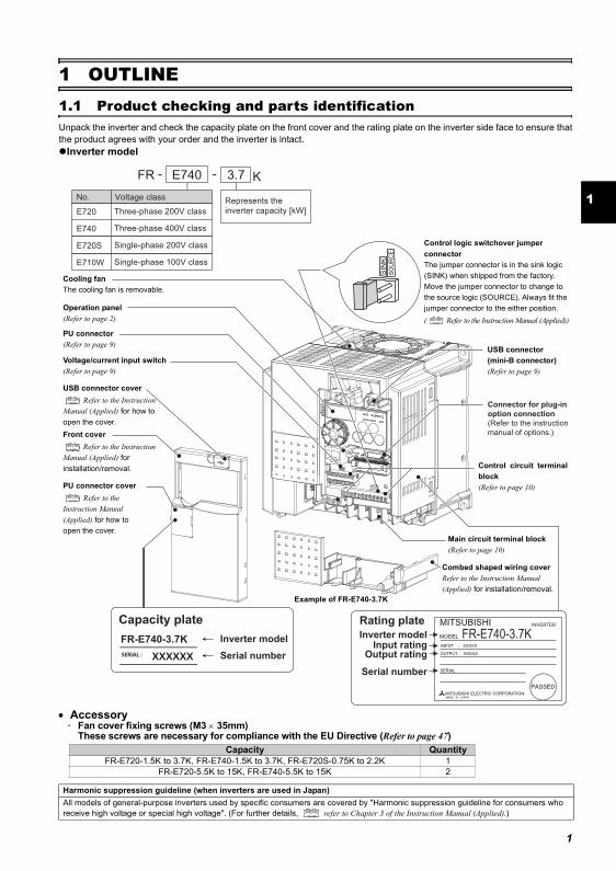
1 OUTLINE1.1 Product checking and parts identificationUnpack the inverter and check the capacity plate on the front cover and the rating plate on the inverter side face to ensure thatthe product agrees with your order and the inverter is intact.
Inverter model
• Accessory· Fan cover fixing screws (M3 × 35mm)
These screws are necessary for compliance with the EU Directive (Refer to page 47)Capacity Quantity
FR-E720-1.5K to 3.7K, FR-E740-1.5K to 3.7K, FR-E720S-0.75K to 2.2K 1FR-E720-5.5K to 15K, FR-E740-5.5K to 15K 2
Harmonic suppression guideline (when inverters are used in Japan)All models of general-purpose inverters used by specific consumers are covered by "Harmonic suppression guideline for consumers who receive high voltage or special high voltage". (For further details, refer to Chapter 3 of the Instruction Manual (Applied).)
Connector for plug-in
option connection
(Refer to the instruction
manual of options.)
Inverter model
Serial number
Capacity plate
FR-E740-3.7K
Rating plate
Inverter modelInput rating
Output rating
Serial number
FR-E740-3.7K
E740 3.7 KFR - -
Represents the
inverter capacity [kW]E720 Three-phase 200V class
E740 Three-phase 400V class
E720S Single-phase 200V class
E710W Single-phase 100V class
No. Voltage class
Cooling fanThe cooling fan is removable.
USB connector(mini-B connector)(Refer to page 9)
Control logic switchover jumper connectorThe jumper connector is in the sink logic (SINK) when shipped from the factory. Move the jumper connector to change to the source logic (SOURCE). Always fit the jumper connector to the either position.( Refer to the Instruction Manual (Applied))
Combed shaped wiring coverRefer to the Instruction Manual (Applied) for installation/removal.
Main circuit terminal block(Refer to page 10)
PU connector cover Refer to the
Instruction Manual (Applied) for how to open the cover.
Front cover Refer to the Instruction
Manual (Applied) for installation/removal.
USB connector cover Refer to the Instruction
Manual (Applied) for how to open the cover.
Voltage/current input switch(Refer to page 9)
Operation panel(Refer to page 2)
PU connector(Refer to page 9)
Example of FR-E740-3.7K
Control circuit terminalblock(Refer to page 10)
Operation panel
1.2 Operation panel
1.2.1 Names and functions of the operation panel
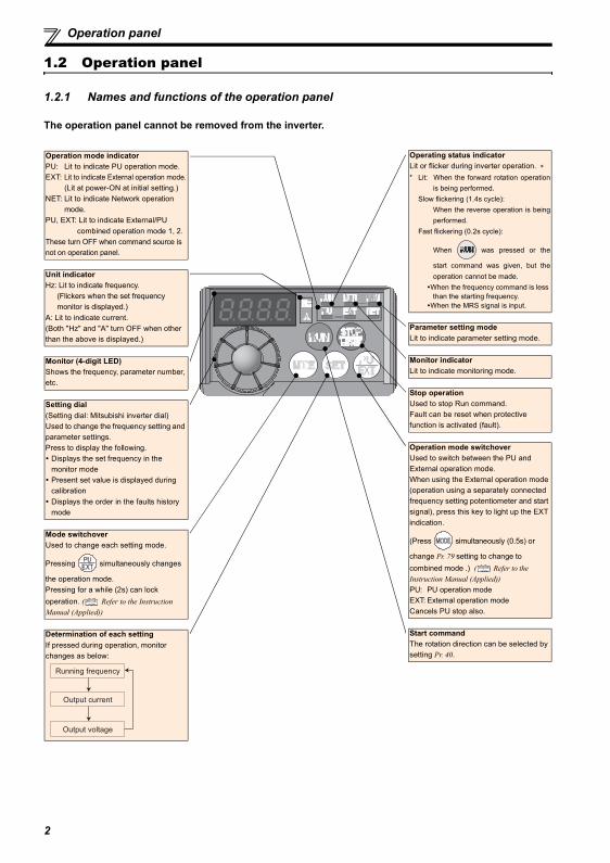
The operation panel cannot be removed from the inverter.
Operation mode indicatorPU: Lit to indicate PU operation mode.EXT: Lit to indicate External operation mode.
(Lit at power-ON at initial setting.)NET: Lit to indicate Network operation
mode.PU, EXT: Lit to indicate External/PU
combined operation mode 1, 2.These turn OFF when command source is not on operation panel.
Unit indicatorHz: Lit to indicate frequency.
(Flickers when the set frequency monitor is displayed.)
A: Lit to indicate current.(Both "Hz" and "A" turn OFF when other than the above is displayed.)
Monitor (4-digit LED)Shows the frequency, parameter number, etc.
Setting dial(Setting dial: Mitsubishi inverter dial)Used to change the frequency setting and parameter settings.Press to display the following.
Displays the set frequency in the monitor modePresent set value is displayed during calibrationDisplays the order in the faults history mode
Mode switchoverUsed to change each setting mode.
Pressing simultaneously changes
the operation mode.Pressing for a while (2s) can lock operation. ( Refer to the Instruction Manual (Applied))
Determination of each settingIf pressed during operation, monitor changes as below:
Running frequency
Output current
Output voltage
Operating status indicatorLit or flicker during inverter operation. ∗* Lit: When the forward rotation operation
is being performed.Slow flickering (1.4s cycle):
When the reverse operation is beingperformed.
Fast flickering (0.2s cycle):
When was pressed or the
start command was given, but theoperation cannot be made.
When the frequency command is less than the starting frequency.
When the MRS signal is input.
Parameter setting modeLit to indicate parameter setting mode.
Monitor indicatorLit to indicate monitoring mode.
Stop operationUsed to stop Run command.Fault can be reset when protective function is activated (fault).
Operation mode switchoverUsed to switch between the PU and External operation mode.When using the External operation mode (operation using a separately connected frequency setting potentiometer and start signal), press this key to light up the EXT indication.
(Press simultaneously (0.5s) or
change Pr. 79 setting to change to combined mode .) ( Refer to the Instruction Manual (Applied))PU: PU operation modeEXT: External operation modeCancels PU stop also.
Start commandThe rotation direction can be selected by setting Pr. 40.
2
1
Operation panel
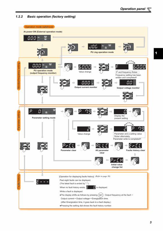
1.2.2 Basic operation (factory setting)
STOP
Operation mode switchover
Para
mete
r settin
gF
aults h
isto
ryM
onitor/
frequency s
ettin
g
At power-ON (External operation mode)
PU operation mode
(output frequency monitor)
Parameter setting mode
PU Jog operation mode
Output current monitor Output voltage monitor
Display the
present setting
Value change
Value change
Parameter write is completed!!
Parameter and a setting value
flicker alternately.
Parameter clear All parameter
clear
Faults history clear
Initial value
change list
(Example)
(Example)
Frequency setting has been
written and completed!!
and frequency flicker.
[Operation for displaying faults history]
Past eight faults can be displayed.
(The latest fault is ended by ".".)
When no fault history exists, is displayed.
While a fault is displayed:
The display shifts as follows by pressing : Output frequency at the fault
Output current Output voltage Energization time.
(After Energization time, it goes back to a fault display.)
Pressing the setting dial shows the fault history number.
(Refer to page 38)
3
4
Operation panel
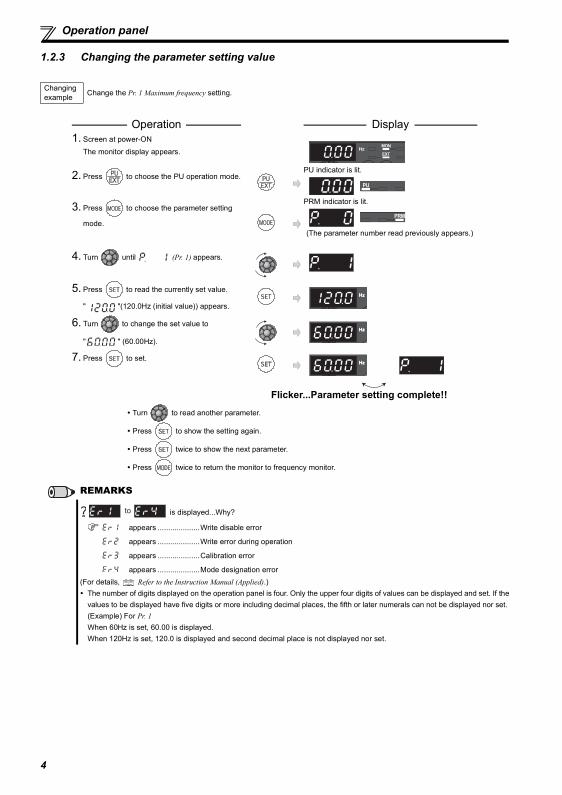
1.2.3 Changing the parameter setting value
Changing example Change the Pr. 1 Maximum frequency setting.
Operation Display 1. Screen at power-ON
The monitor display appears.
2. Press to choose the PU operation mode.PU indicator is lit.
3. Press to choose the parameter setting
mode.
PRM indicator is lit.
(The parameter number read previously appears.)
4. Turn until (Pr. 1) appears.
5. Press to read the currently set value.
" "(120.0Hz (initial value)) appears.
6. Turn to change the set value to
" " (60.00Hz).
7. Press to set.
Flicker...Parameter setting complete!!
Turn to read another parameter.
Press to show the setting again.
Press twice to show the next parameter.
Press twice to return the monitor to frequency monitor.
REMARKS
is displayed...Why?
appears ....................Write disable error
appears ....................Write error during operation
appears ....................Calibration error
appears ....................Mode designation error(For details, Refer to the Instruction Manual (Applied).)
The number of digits displayed on the operation panel is four. Only the upper four digits of values can be displayed and set. If thevalues to be displayed have five digits or more including decimal places, the fifth or later numerals can not be displayed nor set.(Example) For Pr. 1When 60Hz is set, 60.00 is displayed.When 120Hz is set, 120.0 is displayed and second decimal place is not displayed nor set.
to
5
1
Operation panel
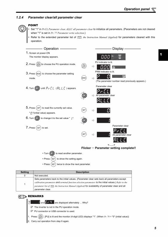
1.2.4 Parameter clear/all parameter clear
POINT Set "1" in Pr.CL Parameter clear, ALLC all parameter clear to initialize all parameters. (Parameters are not cleared
when "1" is set in Pr. 77 Parameter write selection.)
Refer to the extended parameter list of the Instruction Manual (Applied) for parameters cleared with thisoperation.
Operation Display 1. Screen at power-ON
The monitor display appears.
2. Press to choose the PU operation mode.PU indicator is lit.
3. Press to choose the parameter setting
mode.
PRM indicator is lit.
(The parameter number read previously appears.)
4. Turn until ( ) appears.Parameter clear
All parameter clear
5. Press to read the currently set value.
" "(initial value) appears.
6. Turn to change it to the set value " ".
7. Press to set.Parameter clear
All parameter clear
Flicker ··· Parameter setting complete!!
Turn to read another parameter.
Press to show the setting again.
Press twice to show the next parameter.
Setting Description0 Not executed.
1
Sets parameters back to the initial values. (Parameter clear sets back all parameters except calibration parameters and terminal function selection parameters to the initial values.) Refer to the parameter list of the Instruction Manual (Applied) for availability of parameter clear and all parameter clear.
REMARKS
are displayed alternately ... Why?
The inverter is not in the PU operation mode.
PU connector or USB connector is used.
1. Press . [PU] is lit and the monitor (4-digit LED) displays "1". (When Pr. 79 = "0" (initial value))
2. Carry out operation from step 6 again.
and
6
2 INSTALLATION AND WIRING
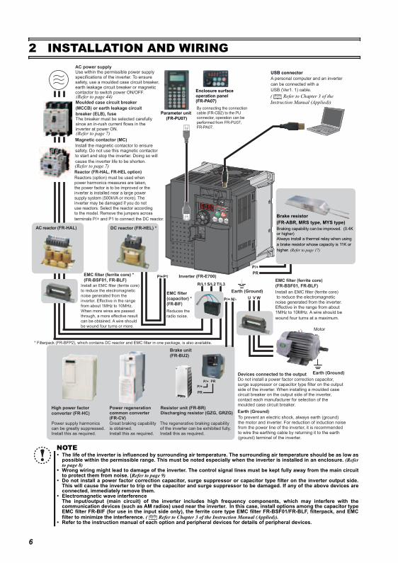
NOTEThe life of the inverter is influenced by surrounding air temperature. The surrounding air temperature should be as low aspossible within the permissible range. This must be noted especially when the inverter is installed in an enclosure. (Referto page 8)Wrong wiring might lead to damage of the inverter. The control signal lines must be kept fully away from the main circuitto protect them from noise. (Refer to page 9)Do not install a power factor correction capacitor, surge suppressor or capacitor type filter on the inverter output side.This will cause the inverter to trip or the capacitor and surge suppressor to be damaged. If any of the above devices areconnected, immediately remove them.Electromagnetic wave interferenceThe input/output (main circuit) of the inverter includes high frequency components, which may interfere with thecommunication devices (such as AM radios) used near the inverter. In this case, install options among the capacitor typeEMC filter FR-BIF (for use in the input side only), the ferrite core type EMC filter FR-BSF01/FR-BLF, filterpack, and EMCfilter to minimize the interference. ( Refer to Chapter 3 of the Instruction Manual (Applied)).Refer to the instruction manual of each option and peripheral devices for details of peripheral devices.
EMC filter (ferrite core)
(FR-BSF01, FR-BLF)
Install an EMC filter (ferrite core) to reduce the electromagnetic noise generated from the inverter.Effective in the range from about 1MHz to 10MHz. A wire should be
wound four turns at a maximum.
Motor
Earth (Ground)
Earth (Ground)
Devices connected to the outputDo not install a power factor correction capacitor, surge suppressor or capacitor type filter on the output side of the inverter. When installing a moulded case circuit breaker on the output side of the inverter, contact each manufacturer for selection of the moulded case circuit breaker.
The regenerative braking capability of the inverter can be exhibited fully.Install this as required.
Power supply harmonics can be greatly suppressed.Install this as required.
High power factor
converter (FR-HC)
Power regeneration common converter (FR-CV)
Earth (Ground)
R/L1 S/L2 T/L3
P1
U W
PR
V
Great braking capability is obtained.Install this as required.
EMC filter (ferrite core) *
(FR-BSF01, FR-BLF)
AC power supplyUse within the permissible power supply specifications of the inverter. To ensure safety, use a moulded case circuit breaker, earth leakage circuit breaker or magnetic contactor to switch power ON/OFF.
Magnetic contactor (MC)
Install the magnetic contactor to ensure safety. Do not use this magnetic contactor to start and stop the inverter. Doing so will
cause the inverter life to be shorten.
Moulded case circuit breaker
(MCCB) or earth leakage circuit
breaker (ELB), fuseThe breaker must be selected carefully since an in-rush current flows in the inverter at power ON.
Install an EMC filter (ferrite core)
to reduce the electromagnetic
noise generated from the
inverter. Effective in the range
from about 1MHz to 10MHz.
When more wires are passed
through, a more effective result
can be obtained. A wire should
be wound four turns or more.
To prevent an electric shock, always earth (ground) the motor and inverter. For reduction of induction noise from the power line of the inverter, it is recommended to wire the earthing cable by returning it to the earth (ground) terminal of the inverter.
AC reactor (FR-HAL) DC reactor (FR-HEL) *
EMC filter
(capacitor) *
(FR-BIF)
P/+
P/+
PR
PR
Brake unit
(FR-BU2)
Reduces the
radio noise.
Resistor unit (FR-BR) Discharging resistor (GZG, GRZG)
Inverter (FR-E700)
* Filterpack (FR-BFP2), which contains DC reactor and EMC filter in one package, is also available.
Parameter unit
(FR-PU07)
By connecting the connection
cable (FR-CB2) to the PU
connector, operation can be
performed from FR-PU07,
FR-PA07.
Enclosure surface operation panel (FR-PA07)
USB connector
A personal computer and an inverter
can be connected with a
USB (Ver1. 1) cable.
Reactor (FR-HAL, FR-HEL option)
Reactors (option) must be used when power harmonics measures are taken, the power factor is to be improved or the inverter is installed near a large power supply system (500kVA or more). The inverter may be damaged if you do not use reactors. Select the reactor according to the model. Remove the jumpers across
terminals P/+ and P1 to connect the DC reactor.
P/+
P/+
P/+
N/-
(Refer to page 44)
(Refer to page 7)
(Refer to page 7)
( Refer to Chapter 3 of the Instruction Manual (Applied))
Brake resistor(FR-ABR, MRS type, MYS type)Braking capability can be improved. (0.4K or higher)Always install a thermal relay when using a brake resistor whose capacity is 11K or higher. (Refer to page 17)
7
2
Peripheral devices
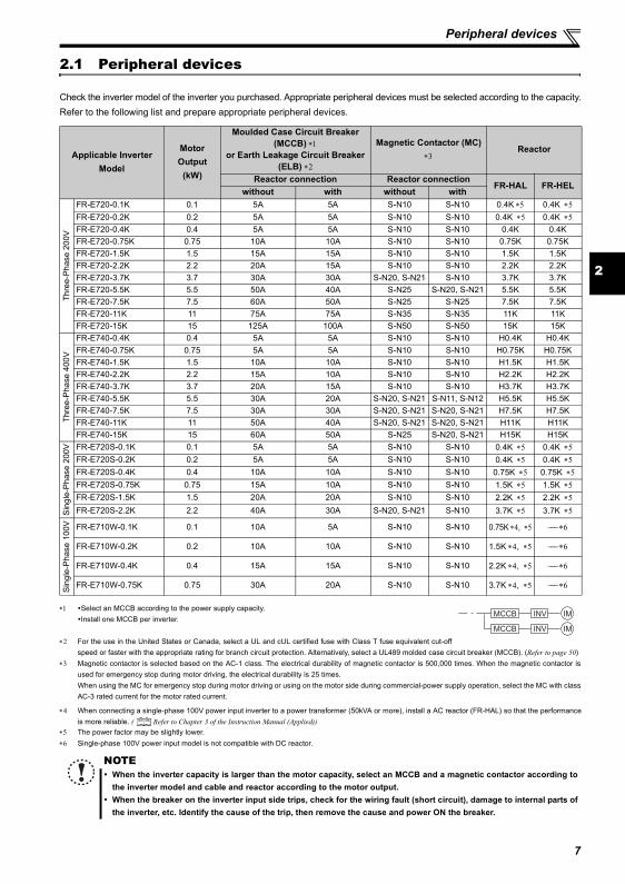
2.1 Peripheral devices
Check the inverter model of the inverter you purchased. Appropriate peripheral devices must be selected according to the capacity.Refer to the following list and prepare appropriate peripheral devices.
∗1 Select an MCCB according to the power supply capacity.Install one MCCB per inverter.
∗2 For the use in the United States or Canada, select a UL and cUL certified fuse with Class T fuse equivalent cut-offspeed or faster with the appropriate rating for branch circuit protection. Alternatively, select a UL489 molded case circuit breaker (MCCB). (Refer to page 50)
∗3 Magnetic contactor is selected based on the AC-1 class. The electrical durability of magnetic contactor is 500,000 times. When the magnetic contactor isused for emergency stop during motor driving, the electrical durability is 25 times.When using the MC for emergency stop during motor driving or using on the motor side during commercial-power supply operation, select the MC with classAC-3 rated current for the motor rated current.
∗5 The power factor may be slightly lower.∗6 Single-phase 100V power input model is not compatible with DC reactor.
Applicable Inverter Model
Motor Output
(kW)
Moulded Case Circuit Breaker (MCCB) ∗1
or Earth Leakage Circuit Breaker (ELB) ∗2
Magnetic Contactor (MC) ∗3
Reactor
Reactor connection Reactor connectionFR-HAL FR-HEL
without with without with
Thre
e-Ph
ase
200V
FR-E720-0.1K 0.1 5A 5A S-N10 S-N10 0.4K ∗5 0.4K ∗5FR-E720-0.2K 0.2 5A 5A S-N10 S-N10 0.4K ∗5 0.4K ∗5FR-E720-0.4K 0.4 5A 5A S-N10 S-N10 0.4K 0.4KFR-E720-0.75K 0.75 10A 10A S-N10 S-N10 0.75K 0.75KFR-E720-1.5K 1.5 15A 15A S-N10 S-N10 1.5K 1.5KFR-E720-2.2K 2.2 20A 15A S-N10 S-N10 2.2K 2.2KFR-E720-3.7K 3.7 30A 30A S-N20, S-N21 S-N10 3.7K 3.7KFR-E720-5.5K 5.5 50A 40A S-N25 S-N20, S-N21 5.5K 5.5KFR-E720-7.5K 7.5 60A 50A S-N25 S-N25 7.5K 7.5KFR-E720-11K 11 75A 75A S-N35 S-N35 11K 11KFR-E720-15K 15 125A 100A S-N50 S-N50 15K 15K
Thre
e-P
hase
400
V
FR-E740-0.4K 0.4 5A 5A S-N10 S-N10 H0.4K H0.4KFR-E740-0.75K 0.75 5A 5A S-N10 S-N10 H0.75K H0.75KFR-E740-1.5K 1.5 10A 10A S-N10 S-N10 H1.5K H1.5KFR-E740-2.2K 2.2 15A 10A S-N10 S-N10 H2.2K H2.2KFR-E740-3.7K 3.7 20A 15A S-N10 S-N10 H3.7K H3.7KFR-E740-5.5K 5.5 30A 20A S-N20, S-N21 S-N11, S-N12 H5.5K H5.5KFR-E740-7.5K 7.5 30A 30A S-N20, S-N21 S-N20, S-N21 H7.5K H7.5KFR-E740-11K 11 50A 40A S-N20, S-N21 S-N20, S-N21 H11K H11KFR-E740-15K 15 60A 50A S-N25 S-N20, S-N21 H15K H15K
Sin
gle-
Pha
se 2
00V FR-E720S-0.1K 0.1 5A 5A S-N10 S-N10 0.4K ∗5 0.4K ∗5
FR-E720S-0.2K 0.2 5A 5A S-N10 S-N10 0.4K ∗5 0.4K ∗5FR-E720S-0.4K 0.4 10A 10A S-N10 S-N10 0.75K ∗5 0.75K ∗5FR-E720S-0.75K 0.75 15A 10A S-N10 S-N10 1.5K ∗5 1.5K ∗5FR-E720S-1.5K 1.5 20A 20A S-N10 S-N10 2.2K ∗5 2.2K ∗5
FR-E720S-2.2K 2.2 40A 30A S-N20, S-N21 S-N10 3.7K ∗5 3.7K ∗5
Sin
gle-
Pha
se 1
00V FR-E710W-0.1K 0.1 10A 5A S-N10 S-N10 0.75K ∗4, ∗5 −−− ∗6
FR-E710W-0.2K 0.2 10A 10A S-N10 S-N10 1.5K ∗4, ∗5 −−− ∗6
FR-E710W-0.4K 0.4 15A 15A S-N10 S-N10 2.2K ∗4, ∗5 −−− ∗6
FR-E710W-0.75K 0.75 30A 20A S-N10 S-N10 3.7K ∗4, ∗5 −−− ∗6
∗4 When connecting a single-phase 100V power input inverter to a power transformer (50kVA or more), install a AC reactor (FR-HAL) so that the performanceis more reliable. ( Refer to Chapter 3 of the Instruction Manual (Applied))
NOTEWhen the inverter capacity is larger than the motor capacity, select an MCCB and a magnetic contactor according tothe inverter model and cable and reactor according to the motor output.When the breaker on the inverter input side trips, check for the wiring fault (short circuit), damage to internal parts ofthe inverter, etc. Identify the cause of the trip, then remove the cause and power ON the breaker.
MCCB INV
MCCB INV
IM
IM
8
Installation of the inverter and instructions
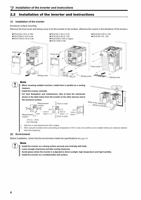
2.2 Installation of the inverter and instructions
(1) Installation of the inverterEnclosure surface mountingRemove the front cover and wiring cover to fix the inverter to the surface. (Remove the covers in the directions of the arrows.)
(2) EnvironmentBefore installation, check that the environment meets the specifications on page 45.
NoteWhen encasing multiple inverters, install them in parallel as a coolingmeasure.Install the inverter vertically.For heat dissipation and maintenance, take at least the clearancesshown in the table below from the inverter to the other devices and tothe enclosure surface.
∗1 Take 5cm or more clearances for 5.5K or higher.∗2 When using the inverters at the surrounding air temperature of 40°C or less, the inverters can be installed without any clearance between
them (0cm clearance).
NoteInstall the inverter on a strong surface securely and vertically with bolts.Leave enough clearances and take cooling measures.Avoid places where the inverter is subjected to direct sunlight, high temperature and high humidity.Install the inverter on a nonflammable wall surface.
Front cover
Wiring cover
Front cover
Wiring cover
FR-E720-0.1K to 0.75K
FR-E720S-0.1K to 0.4K
FR-E710W-0.1K to 0.4K
FR-E720-1.5K to 3.7K
FR-E740-0.4K to 7.5K
FR-E720S-0.75K or higher
FR-E710W-0.75K
Front cover 1
FR-E720-5.5K to 15K
FR-E740-11K, 15K
Wiring cover
Refer to the clearances shown on the left.
Vert
ical
10cm or more
10cm or more
Measurement
position
Measurement
position
5cm 5cm
5cm
-10 C to +50 C
(non-freezing)
1cm or
more ∗1, ∗2
1cm or
more ∗1, ∗21cm or
more ∗1
9
2
Wiring
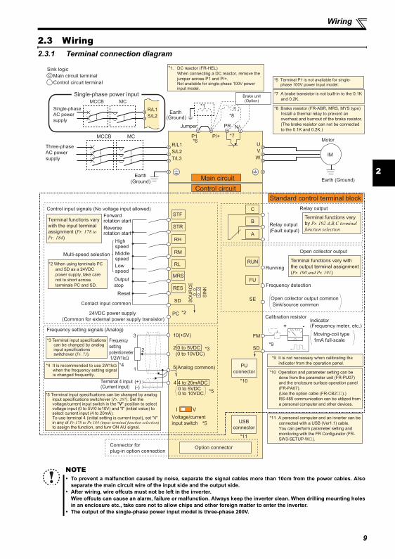
2.3 Wiring2.3.1 Terminal connection diagram
NOTETo prevent a malfunction caused by noise, separate the signal cables more than 10cm from the power cables. Alsoseparate the main circuit wire of the input side and the output side.After wiring, wire offcuts must not be left in the inverter.Wire offcuts can cause an alarm, failure or malfunction. Always keep the inverter clean. When drilling mounting holesin an enclosure etc., take care not to allow chips and other foreign matter to enter the inverter.The output of the single-phase power input model is three-phase 200V.
Earth (Ground)
Motor
IM
Earth (Ground)
Three-phase
AC power
supply
MCCB MC
R/L1
P1 P/+
PR N/-
S/L2
T/L3
U
V
W
Earth
(Ground)
*8 Brake resistor (FR-ABR, MRS, MYS type)
Install a thermal relay to prevent an
overheat and burnout of the brake resistor.
(The brake resistor can not be connected
to the 0.1K and 0.2K.)
*7 A brake transistor is not built-in to the 0.1K
and 0.2K.
Forward rotation start
Reverse rotation start
Middle speed
High speed
Low speed
Output
stop
Reset
Control input signals (No voltage input allowed)
Contact input common
24VDC power supply
(Common for external power supply transistor)
STR
STF
RH
RM
RL
MRS
SD
PC
Relay output
Running
Frequency detection
Open collector output
Open collector output common
Sink/source common
FU
RUN
SE
A
B
C
FM
SD
Indicator(Frequency meter, etc.)+ -
Moving-coil type
1mA full-scale
Calibration resistor
Frequency setting signals (Analog)
2 0 to 5VDC
10(+5V)
2
3
1
Frequency
setting
potentiometer1/2W1kΩ
5(Analog common)*4
Connector for
plug-in option connectionOption connector
*3 Terminal input specifications can be changed by analog input specifications switchover (Pr. 73).
*2 When using terminals PC
and SD as a 24VDC
power supply, take care
not to short across
terminals PC and SD.
PU
connector
*9 It is not necessary when calibrating the
indicator from the operation panel.
*1. DC reactor (FR-HEL)
When connecting a DC reactor, remove the
jumper across P1 and P/+. Not available for single-phase 100V power input model.
Control circuit terminal
Main circuit terminal
Sink logic
Jumper
*1
*8
*7*6
*2
*3*9
*10
USB
connector
*11
Terminal functions vary
with the input terminal
assignment (Pr. 178 to
Pr. 184)
Multi-speed selection
Terminal functions vary with
the output terminal assignment
(Pr. 190 and Pr. 191)
Terminal functions vary
by Pr. 192 A,B,C terminal
function selection
SIN
K
SO
UR
CE
I V
*5
(0 to 10VDC)
Voltage/current
input switch
Main circuit
Control circuit
Standard control terminal block
R
RES
Relay output
(Fault output)
Brake unit(Option)
Single-phase
AC power
supply
MCCB MC
R/L1
S/L2
Single-phase power input
*6 Terminal P1 is not available for single-phase 100V power input model.
Terminal 4 input(Current input)
(+)(-)
4 4 to 20mADC
*50 to 5VDC0 to 10VDC*5 Terminal input specifications can be changed by analog
input specifications switchover (Pr. 267). Set the voltage/current input switch in the "V" position to select voltage input (0 to 5V/0 to10V) and "I" (initial value) to select current input (4 to 20mA). To use terminal 4 (initial setting is current input), set "4" in any of Pr.178 to Pr.184 (input terminal function selection) to assign the function, and turn ON AU signal.
*4 It is recommended to use 2W1kΩ when the frequency setting signal is changed frequently.
*10 Operation and parameter setting can be
done from the parameter unit (FR-PU07)
and the enclosure surface operation panel
(FR-PA07).
(Use the option cable (FR-CB2 ).)
RS-485 communication can be utilized from
a personal computer and other devices.
*11 A personal computer and an inverter can be
connected with a USB (Ver1.1) cable.
You can perform parameter setting and
monitoring with the FR Configurator (FR-
SW3-SETUP-W ).
Wiring
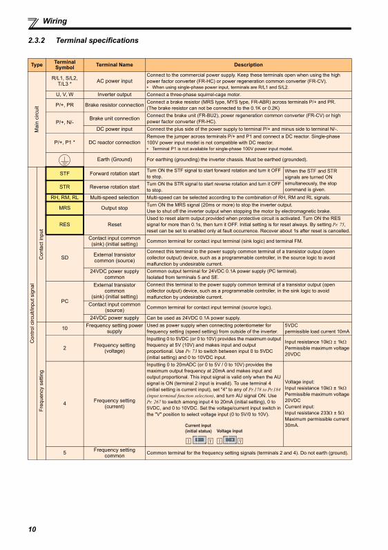
2.3.2 Terminal specifications
Type Terminal Symbol Terminal Name Description
Mai
n ci
rcui
t
R/L1, S/L2, T/L3 * AC power input
Connect to the commercial power supply. Keep these terminals open when using the high power factor converter (FR-HC) or power regeneration common converter (FR-CV).∗ When using single-phase power input, terminals are R/L1 and S/L2.
U, V, W Inverter output Connect a three-phase squirrel-cage motor.
P/+, PR Brake resistor connection Connect a brake resistor (MRS type, MYS type, FR-ABR) across terminals P/+ and PR.(The brake resistor can not be connected to the 0.1K or 0.2K)
P/+, N/-Brake unit connection Connect the brake unit (FR-BU2), power regeneration common converter (FR-CV) or high
power factor converter (FR-HC).DC power input Connect the plus side of the power supply to terminal P/+ and minus side to terminal N/-.
P/+, P1 * DC reactor connectionRemove the jumper across terminals P/+ and P1 and connect a DC reactor. Single-phase 100V power input model is not compatible with DC reactor.∗ Terminal P1 is not available for single-phase 100V power input model.
Earth (Ground) For earthing (grounding) the inverter chassis. Must be earthed (grounded).
Con
trol c
ircui
t/inp
ut s
igna
l
Con
tact
inpu
t
STF Forward rotation start Turn ON the STF signal to start forward rotation and turn it OFF to stop.
When the STF and STR signals are turned ON simultaneously, the stop command is given. STR Reverse rotation start Turn ON the STR signal to start reverse rotation and turn it OFF
to stop.RH, RM, RL Multi-speed selection Multi-speed can be selected according to the combination of RH, RM and RL signals.
MRS Output stop Turn ON the MRS signal (20ms or more) to stop the inverter output.Use to shut off the inverter output when stopping the motor by electromagnetic brake.
RES ResetUsed to reset alarm output provided when protective circuit is activated. Turn ON the RES signal for more than 0.1s, then turn it OFF. Initial setting is for reset always. By setting Pr. 75, reset can be set to enabled only at fault occurrence. Recover about 1s after reset is cancelled.
SD
Contact input common(sink) (initial setting) Common terminal for contact input terminal (sink logic) and terminal FM.
External transistor common (source)
Connect this terminal to the power supply common terminal of a transistor output (open collector output) device, such as a programmable controller, in the source logic to avoid malfunction by undesirable current.
24VDC power supply common
Common output terminal for 24VDC 0.1A power supply (PC terminal).Isolated from terminals 5 and SE.
PC
External transistor common
(sink) (initial setting)
Connect this terminal to the power supply common terminal of a transistor output (open collector output) device, such as a programmable controller, in the sink logic to avoid malfunction by undesirable current.
Contact input common (source) Common terminal for contact input terminal (source logic).
24VDC power supply Can be used as 24VDC 0.1A power supply.
Freq
uenc
y se
tting
10 Frequency setting power supply
Used as power supply when connecting potentiometer for frequency setting (speed setting) from outside of the inverter.
5VDCpermissible load current 10mA
2 Frequency setting (voltage)
Inputting 0 to 5VDC (or 0 to 10V) provides the maximum output frequency at 5V (10V) and makes input and output proportional. Use Pr. 73 to switch between input 0 to 5VDC (initial setting) and 0 to 10VDC input.
Input resistance 10kΩ ± 1kΩPermissible maximum voltage 20VDC
4 Frequency setting (current)
Inputting 0 to 20mADC (or 0 to 5V / 0 to 10V) provides the maximum output frequency at 20mA and makes input and output proportional. This input signal is valid only when the AU signal is ON (terminal 2 input is invalid). To use terminal 4 (initial setting is current input), set "4" to any of Pr.178 to Pr.184 (input terminal function selection), and turn AU signal ON. Use Pr. 267 to switch among input 4 to 20mA (initial setting), 0 to 5VDC, and 0 to 10VDC. Set the voltage/current input switch in the "V" position to select voltage input (0 to 5V/0 to 10V).
Voltage input: Input resistance 10kΩ ± 1kΩPermissible maximum voltage 20VDCCurrent input: Input resistance 233Ω ± 5ΩMaximum permissible current 30mA.
5 Frequency setting common Common terminal for the frequency setting signals (terminals 2 and 4). Do not earth (ground).
Voltage input
Current input
(initial status)
10
2
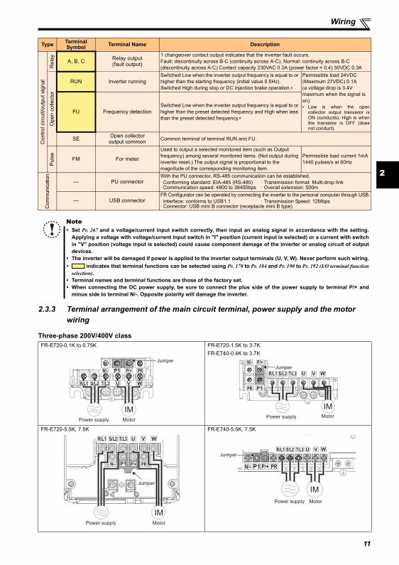
Wiring
2.3.3 Terminal arrangement of the main circuit terminal, power supply and the motor wiring
Three-phase 200V/400V class
Con
trol c
ircui
t/out
put s
igna
l
Rel
ay A, B, C Relay output (fault output)
1 changeover contact output indicates that the inverter fault occurs.Fault: discontinuity across B-C (continuity across A-C), Normal: continuity across B-C (discontinuity across A-C) Contact capacity 230VAC 0.3A (power factor = 0.4) 30VDC 0.3A
Ope
n co
llect
or
RUN Inverter runningSwitched Low when the inverter output frequency is equal to or higher than the starting frequency (initial value 0.5Hz). Switched High during stop or DC injection brake operation.∗
Permissible load 24VDC (Maximum 27VDC) 0.1A(a voltage drop is 3.4V maximum when the signal is on)∗ Low is when the open
collector output transistor isON (conducts). High is whenthe transistor is OFF (doesnot conduct).
FU Frequency detectionSwitched Low when the inverter output frequency is equal to or higher than the preset detected frequency and High when less than the preset detected frequency.∗
SE Open collectoroutput common Common terminal of terminal RUN and FU.
Pul
se FM For meter
Used to output a selected monitored item (such as Output frequency) among several monitored items. (Not output during inverter reset.) The output signal is proportional to the magnitude of the corresponding monitoring item.
Permissible load current 1mA1440 pulses/s at 60Hz
Com
mun
icatio
n
— PU connectorWith the PU connector, RS-485 communication can be established.· Conforming standard: EIA-485 (RS-485) · Transmission format: Multi-drop link· Communication speed: 4800 to 38400bps · Overall extension: 500m
— USB connectorFR Configurator can be operated by connecting the inverter to the personal computer through USB.· Interface: conforms to USB1.1 · Transmission Speed: 12Mbps· Connector: USB mini B connector (receptacle mini B type)
NoteSet Pr. 267 and a voltage/current input switch correctly, then input an analog signal in accordance with the setting.Applying a voltage with voltage/current input switch in "I" position (current input is selected) or a current with switchin "V" position (voltage input is selected) could cause component damage of the inverter or analog circuit of outputdevices.The inverter will be damaged if power is applied to the inverter output terminals (U, V, W). Never perform such wiring.
indicates that terminal functions can be selected using Pr. 178 to Pr. 184 and Pr. 190 to Pr. 192 (I/O terminal functionselection).Terminal names and terminal functions are those of the factory set. When connecting the DC power supply, be sure to connect the plus side of the power supply to terminal P/+ andminus side to terminal N/-. Opposite polarity will damage the inverter.
FR-E720-0.1K to 0.75K FR-E720-1.5K to 3.7KFR-E740-0.4K to 3.7K
FR-E720-5.5K, 7.5K FR-E740-5.5K, 7.5K
Type Terminal Symbol Terminal Name Description
MotorPower supply
N/- P/+ PR
IM
R/L1 S/L2 T/L3
Jumper
MotorPower supply
N/- P/+
PR
IM
R/L1 S/L2 T/L3
Jumper
MotorPower supply
IM
N/- P/+ PR
R/L1 S/L2 T/L3
Jumper
N/- P/+ PR
R/L1 S/L2 T/L3
MotorPower supply
Jumper
IM
11
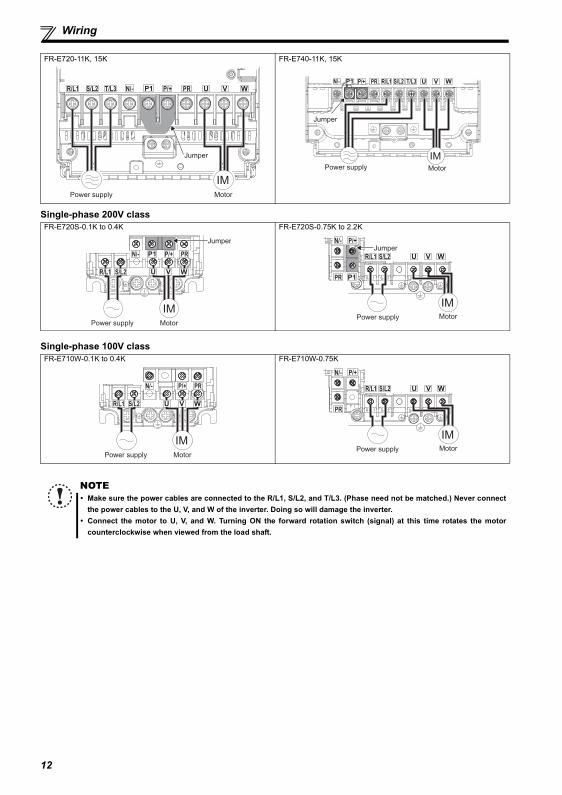
Wiring
Single-phase 200V class
Single-phase 100V class
FR-E720-11K, 15K FR-E740-11K, 15K
FR-E720S-0.1K to 0.4K FR-E720S-0.75K to 2.2K
FR-E710W-0.1K to 0.4K FR-E710W-0.75K
NOTEMake sure the power cables are connected to the R/L1, S/L2, and T/L3. (Phase need not be matched.) Never connectthe power cables to the U, V, and W of the inverter. Doing so will damage the inverter.Connect the motor to U, V, and W. Turning ON the forward rotation switch (signal) at this time rotates the motorcounterclockwise when viewed from the load shaft.
N/- P/+ PRR/L1 S/L2 T/L3
Jumper
MotorPower supply
IM
MotorPower supply
IM
N/- P/+ PR R/L1 S/L2 T/L3
Jumper
MotorPower supply
N/- P/+ PR
IM
R/L1 S/L2
Jumper
MotorPower supply
N/- P/+
PR
IM
R/L1 S/L2
Jumper
MotorPower supply
N/- P/+ PR
IM
R/L1 S/L2
MotorPower supply
N/- P/+
PR
IM
R/L1 S/L2
12
2
Wiring
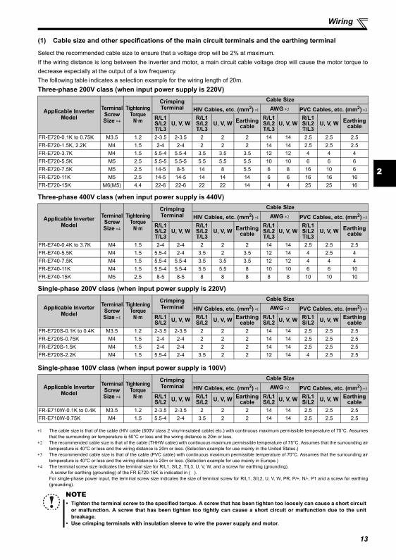
(1) Cable size and other specifications of the main circuit terminals and the earthing terminal
Select the recommended cable size to ensure that a voltage drop will be 2% at maximum.If the wiring distance is long between the inverter and motor, a main circuit cable voltage drop will cause the motor torque todecrease especially at the output of a low frequency.The following table indicates a selection example for the wiring length of 20m.Three-phase 200V class (when input power supply is 220V)
Three-phase 400V class (when input power supply is 440V)
Single-phase 200V class (when input power supply is 220V)
Single-phase 100V class (when input power supply is 100V)
∗1 The cable size is that of the cable (HIV cable (600V class 2 vinyl-insulated cable) etc.) with continuous maximum permissible temperature of 75°C. Assumesthat the surrounding air temperature is 50°C or less and the wiring distance is 20m or less.
∗2 The recommended cable size is that of the cable (THHW cable) with continuous maximum permissible temperature of 75°C. Assumes that the surrounding airtemperature is 40°C or less and the wiring distance is 20m or less. (Selection example for use mainly in the United States.)
∗3 The recommended cable size is that of the cable (PVC cable) with continuous maximum permissible temperature of 70°C. Assumes that the surrounding airtemperature is 40°C or less and the wiring distance is 20m or less. (Selection example for use mainly in Europe.)
∗4 The terminal screw size indicates the terminal size for R/L1, S/L2, T/L3, U, V, W, and a screw for earthing (grounding). A screw for earthing (grounding) of the FR-E720-15K is indicated in ( ). For single-phase power input, the terminal screw size indicates the size of terminal screw for R/L1, S/L2, U, V, W, PR, P/+, N/-, P1 and a screw for earthing(grounding).
Applicable InverterModel
Terminal ScrewSize ∗4
TighteningTorque
N·m
Crimping Terminal
Cable Size
HIV Cables, etc. (mm2) ∗1 AWG ∗2 PVC Cables, etc. (mm2) ∗3
R/L1S/L2T/L3
U, V, WR/L1S/L2T/L3
U, V, W Earthing cable
R/L1S/L2T/L3
U, V, WR/L1S/L2T/L3
U, V, W Earthing cable
FR-E720-0.1K to 0.75K M3.5 1.2 2-3.5 2-3.5 2 2 2 14 14 2.5 2.5 2.5FR-E720-1.5K, 2.2K M4 1.5 2-4 2-4 2 2 2 14 14 2.5 2.5 2.5FR-E720-3.7K M4 1.5 5.5-4 5.5-4 3.5 3.5 3.5 12 12 4 4 4FR-E720-5.5K M5 2.5 5.5-5 5.5-5 5.5 5.5 5.5 10 10 6 6 6FR-E720-7.5K M5 2.5 14-5 8-5 14 8 5.5 6 8 16 10 6FR-E720-11K M5 2.5 14-5 14-5 14 14 14 6 6 16 16 16FR-E720-15K M6(M5) 4.4 22-6 22-6 22 22 14 4 4 25 25 16
Applicable InverterModel
Terminal ScrewSize ∗4
TighteningTorque
N·m
Crimping Terminal
Cable Size
HIV Cables, etc. (mm2) ∗1 AWG ∗2 PVC Cables, etc. (mm2) ∗3
R/L1S/L2T/L3
U, V, WR/L1S/L2T/L3
U, V, W Earthing cable
R/L1S/L2T/L3
U, V, WR/L1S/L2T/L3
U, V, W Earthing cable
FR-E740-0.4K to 3.7K M4 1.5 2-4 2-4 2 2 2 14 14 2.5 2.5 2.5FR-E740-5.5K M4 1.5 5.5-4 2-4 3.5 2 3.5 12 14 4 2.5 4FR-E740-7.5K M4 1.5 5.5-4 5.5-4 3.5 3.5 3.5 12 12 4 4 4FR-E740-11K M4 1.5 5.5-4 5.5-4 5.5 5.5 8 10 10 6 6 10FR-E740-15K M5 2.5 8-5 8-5 8 8 8 8 8 10 10 10
Applicable InverterModel
Terminal ScrewSize ∗4
TighteningTorque
N·m
Crimping Terminal
Cable Size
HIV Cables, etc. (mm2) ∗1 AWG ∗2 PVC Cables, etc. (mm2) ∗3
R/L1S/L2 U, V, W R/L1
S/L2 U, V, W Earthing cable
R/L1S/L2 U, V, W R/L1
S/L2 U, V, W Earthing cable
FR-E720S-0.1K to 0.4K M3.5 1.2 2-3.5 2-3.5 2 2 2 14 14 2.5 2.5 2.5FR-E720S-0.75K M4 1.5 2-4 2-4 2 2 2 14 14 2.5 2.5 2.5FR-E720S-1.5K M4 1.5 2-4 2-4 2 2 2 14 14 2.5 2.5 2.5FR-E720S-2.2K M4 1.5 5.5-4 2-4 3.5 2 2 12 14 4 2.5 2.5
Applicable InverterModel
Terminal ScrewSize ∗4
TighteningTorque
N·m
Crimping Terminal
Cable Size
HIV Cables, etc. (mm2) ∗1 AWG ∗2 PVC Cables, etc. (mm2) ∗3
R/L1S/L2 U, V, W R/L1
S/L2 U, V, W Earthing cable
R/L1S/L2 U, V, W R/L1
S/L2 U, V, W Earthing cable
FR-E710W-0.1K to 0.4K M3.5 1.2 2-3.5 2-3.5 2 2 2 14 14 2.5 2.5 2.5FR-E710W-0.75K M4 1.5 5.5-4 2-4 3.5 2 2 14 14 2.5 2.5 2.5
NOTETighten the terminal screw to the specified torque. A screw that has been tighten too loosely can cause a short circuitor malfunction. A screw that has been tighten too tightly can cause a short circuit or malfunction due to the unitbreakage.Use crimping terminals with insulation sleeve to wire the power supply and motor.
13
Wiring
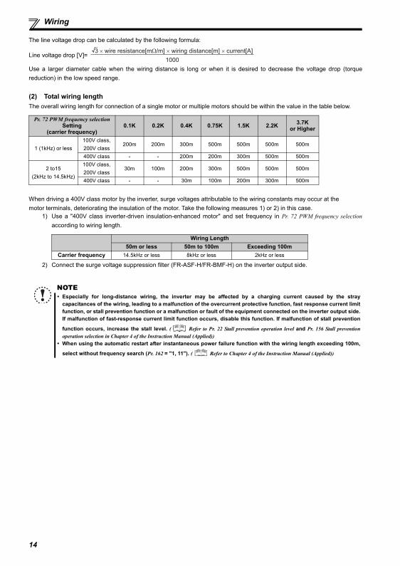
The line voltage drop can be calculated by the following formula:
Line voltage drop [V]=
Use a larger diameter cable when the wiring distance is long or when it is desired to decrease the voltage drop (torquereduction) in the low speed range.
(2) Total wiring lengthThe overall wiring length for connection of a single motor or multiple motors should be within the value in the table below.
When driving a 400V class motor by the inverter, surge voltages attributable to the wiring constants may occur at themotor terminals, deteriorating the insulation of the motor. Take the following measures 1) or 2) in this case.
1) Use a "400V class inverter-driven insulation-enhanced motor" and set frequency in Pr. 72 PWM frequency selectionaccording to wiring length.
2) Connect the surge voltage suppression filter (FR-ASF-H/FR-BMF-H) on the inverter output side.
Pr. 72 PWM frequency selection Setting
(carrier frequency)0.1K 0.2K 0.4K 0.75K 1.5K 2.2K 3.7K
or Higher
1 (1kHz) or less100V class, 200V class
200m 200m 300m 500m 500m 500m 500m
400V class - - 200m 200m 300m 500m 500m
2 to15(2kHz to 14.5kHz)
100V class, 200V class
30m 100m 200m 300m 500m 500m 500m
400V class - - 30m 100m 200m 300m 500m
Wiring Length50m or less 50m to 100m Exceeding 100m
Carrier frequency 14.5kHz or less 8kHz or less 2kHz or less
NOTEEspecially for long-distance wiring, the inverter may be affected by a charging current caused by the straycapacitances of the wiring, leading to a malfunction of the overcurrent protective function, fast response current limitfunction, or stall prevention function or a malfunction or fault of the equipment connected on the inverter output side.If malfunction of fast-response current limit function occurs, disable this function. If malfunction of stall prevention
function occurs, increase the stall level. ( Refer to Pr. 22 Stall prevention operation level and Pr. 156 Stall preventionoperation selection in Chapter 4 of the Instruction Manual (Applied))When using the automatic restart after instantaneous power failure function with the wiring length exceeding 100m,
select without frequency search (Pr. 162 = "1, 11"). ( Refer to Chapter 4 of the Instruction Manual (Applied))
3 × wire resistance[mΩ/m] × wiring distance[m] × current[A]
1000
14
2
Wiring
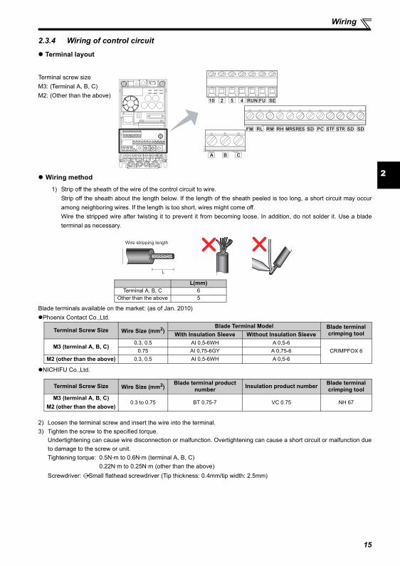
2.3.4 Wiring of control circuit
Terminal layout
Wiring method
1) Strip off the sheath of the wire of the control circuit to wire.Strip off the sheath about the length below. If the length of the sheath peeled is too long, a short circuit may occuramong neighboring wires. If the length is too short, wires might come off.Wire the stripped wire after twisting it to prevent it from becoming loose. In addition, do not solder it. Use a bladeterminal as necessary.
Blade terminals available on the market: (as of Jan. 2010)Phoenix Contact Co.,Ltd.
NICHIFU Co.,Ltd.
2) Loosen the terminal screw and insert the wire into the terminal.3) Tighten the screw to the specified torque.
Undertightening can cause wire disconnection or malfunction. Overtightening can cause a short circuit or malfunction dueto damage to the screw or unit.Tightening torque: 0.5N·m to 0.6N·m (terminal A, B, C)
0.22N·m to 0.25N·m (other than the above)Screwdriver: Small flathead screwdriver (Tip thickness: 0.4mm/tip width: 2.5mm)
Terminal screw sizeM3: (Terminal A, B, C)M2: (Other than the above)
L(mm)Terminal A, B, C 6
Other than the above 5
Terminal Screw Size Wire Size (mm2)Blade Terminal Model Blade terminal
crimping toolWith Insulation Sleeve Without Insulation Sleeve
M3 (terminal A, B, C)0.3, 0.5 AI 0,5-6WH A 0,5-6
CRIMPFOX 60.75 AI 0,75-6GY A 0,75-6M2 (other than the above) 0.3, 0.5 AI 0,5-6WH A 0,5-6
Terminal Screw Size Wire Size (mm2)Blade terminal product
number Insulation product number Blade terminalcrimping tool
M3 (terminal A, B, C)M2 (other than the above)
0.3 to 0.75 BT 0.75-7 VC 0.75 NH 67
SDSDSTF STRPCSDRESMRSRHRMRLFM
CBA
10 2 5 4 RUN FU SE
L
Wire stripping length
15

Wiring
(1) Control circuit common terminals (SD, 5, SE)Terminals SD, SE and 5 are common terminals for I/O signals. (All common terminals are isolated from each other.) Do notearth them. Avoid connecting the terminals SD and 5 and the terminals SE and 5.Terminal SD is a common terminal for the contact input terminals (STF, STR, RH, RM, RL, MRS, RES) and frequency outputsignal (FM). The open collector circuit is isolated from the internal control circuit by photocoupler.Terminal 5 is a common terminal for the frequency setting signals (terminal 2 or 4). It should be protected from external noiseusing a shielded or twisted wire.Terminal SE is a common terminal for the open collector output terminal (RUN, FU). The contact input circuit is isolated fromthe internal control circuit by photocoupler.
(2) Wiring instructions
1) It is recommended to use the wires of 0.3mm2 to 0.75mm2 gauge for connection to the control circuit terminals.2) The maximum wiring length should be 30m (200m for terminal FM).3) Do not short terminals PC and SD. Inverter may be damaged.4) Use two or more parallel micro-signal contacts or twin contacts to prevent
contact faults when using contact inputs since the control circuit input signalsare micro-currents.
5) Use shielded or twisted wires for connection to the control circuit terminals andrun them away from the main and power circuits (including the 200V relaysequence circuit).
6) Do not apply a voltage to the contact input terminals (e.g. STF) of the controlcircuit.
7) Always apply a voltage to the fault output terminals (A, B, C) via a relay coil, lamp, etc.
Micro signal contacts Twin contacts
16
17
2
Connection of a dedicated external brake resistor (MRS type, MYS type, FR-ABR)
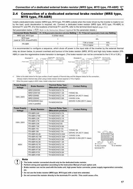
2.4 Connection of a dedicated external brake resistor (MRS type, MYS type, FR-ABR)
Install a dedicated brake resistor (MRS type, MYS type, FR-ABR) outside when the motor driven by the inverter is made to runby the load, quick deceleration is required, etc. Connect a dedicated brake resistor (MRS type, MYS type, FR-ABR) toterminal P/+ and PR. (For the locations of terminal P/+ and PR, refer to the terminal block layout (page 11).)Set parameters below. ( Refer to the Instruction Manual (Applied) for the parameter details.)
It is recommended to configure a sequence, which shuts off power in the input side of the inverter by the external thermalrelay as shown below, to prevent overheat and burnout of the brake resistor (MRS, MYS) and high duty brake resistor (FR-ABR) in case the regenerative brake transistor is damaged. (The brake resistor can not be connected to the 0.1K or 0.2K.)
∗1 Refer to the table below for the type number of each capacity of thermal relay and the diagram below for the connection. (Always install a thermal relay when using a brake resistor whose capacity is 11K or higher)
∗2 When the power supply is 400V class, install a step-down transformer.
Connected Brake Resistor Pr. 30 Regenerative function selection Setting Pr. 70 Special regenerative brake duty SettingMRS type, MYS type 0 (initial value) —
MYS type (used at 100% torque/6%ED) 1 6%
FR-ABR 17.5K or lower 10%11K or higher 6%
Power Supply Voltage Brake Resistor Thermal Relay Type
(Mitsubishi product) Contact Rating
100V, 200V
MRS120W200 TH-N20CXHZ-0.7A110VAC 5A, 220VAC 2A (AC11 class)110VDC 0.5A, 220VDC 0.25A (DC11 class)
MRS120W100 TH-N20CXHZ-1.3AMRS120W60 TH-N20CXHZ-2.1AMRS120W40 TH-N20CXHZ-3.6AMYS220W50 (two units in parallel)
TH-N20CXHZ-5A
Power Supply Voltage Brake Resistor Thermal Relay Type
(Mitsubishi product) Contact Rating
100V, 200V
FR-ABR-0.4K TH-N20CXHZ-0.7A
110VAC 5A220VAC 2A (AC11 class)110VDC 0.5A, 220VDC 0.25A (DC11 class)
FR-ABR-0.75K TH-N20CXHZ-1.3AFR-ABR-2.2K TH-N20CXHZ-2.1AFR-ABR-3.7K TH-N20CXHZ-3.6AFR-ABR-5.5K TH-N20CXHZ-5AFR-ABR-7.5K TH-N20CXHZ-6.6AFR-ABR-11K TH-N20CXHZ-11AFR-ABR-15K TH-N20CXHZ-11A
400V
FR-ABR-H0.4K TH-N20CXHZ-0.24AFR-ABR-H0.75K TH-N20CXHZ-0.35AFR-ABR-H1.5K TH-N20CXHZ-0.9AFR-ABR-H2.2K TH-N20CXHZ-1.3AFR-ABR-H3.7K TH-N20CXHZ-2.1AFR-ABR-H5.5K TH-N20CXHZ-2.5AFR-ABR-H7.5K TH-N20CXHZ-3.6AFR-ABR-H11K TH-N20CXHZ-6.6AFR-ABR-H15K TH-N20CXHZ-6.6A
NoteThe brake resistor connected should only be the dedicated brake resistor.Perform wiring and operation according to the Instruction Manual of each option unit.Brake resistor can not be used with the brake unit, high power factor converter, power supply regeneration converter,etc.Do not use the brake resistor (MRS type, MYS type) with a lead wire extended.Do not connect the resistor directly to the terminals P/+ and N/-. This could cause a fire.
MC Inverter
MC
R
PR
P/+
S/L2
T/L3
R/L1
ON OFF
OCR
Contact
Power supply
F
<Example 1> High-duty brake
resistor (FR-ABR)
T
MC
Thermal relay(OCR) (*1)
*2
Inverter
MC
R
PR
P/+
S/L2
T/L3
R/L1
ON OFF
B
C
Power supply
F
<Example 2>MC
High-duty brake
resistor (FR-ABR)
OCR
Contact
T
MC
Thermal relay(OCR) (*1)
*2
To the inverter
terminal P/+
To a resistor
TH-N20
1/L1 5/L3
2/T1 6/T3
PRECAUTIONS FOR USE OF THE INVERTER
3 PRECAUTIONS FOR USE OF THE INVERTER
The FR-E700 series is a highly reliable product, but incorrect peripheral circuit making or operation/handling method mayshorten the product life or damage the product.Before starting operation, always recheck the following points.
(1) Use crimping terminals with insulation sleeve to wire the power supply and motor.
(2) Application of power to the output terminals (U, V, W) of the inverter will damage the inverter. Never performsuch wiring.
(3) After wiring, wire offcuts must not be left in the inverter.Wire offcuts can cause an alarm, failure or malfunction. Always keep the inverter clean.When drilling mounting holes in an enclosure etc., take care not to allow chips and other foreign matter to enter theinverter.
(4) Use cables of the size to make a voltage drop 2% or less.If the wiring distance is long between the inverter and motor, a main circuit cable voltage drop will cause the motor torqueto decrease especially at the output of a low frequency.Refer to page 13 for the recommended wire sizes.
(5) The overall wiring length should be 500m or less.Especially for long distance wiring, the fast-response current limit function may decrease or the equipment connected tothe secondary side may malfunction or become faulty under the influence of a charging current due to the stray capacityof the wiring. Therefore, note the overall wiring length. (Refer to page 14)
(6) Electromagnetic wave interferenceThe input/output (main circuit) of the inverter includes high frequency components, which may interfere with thecommunication devices (such as AM radios) used near the inverter. In this case, install options among the capacitor typeEMC filter FR-BIF (for use in the input side only), the ferrite core type EMC filter FR-BSF01/FR-BLF, filterpack, and EMCfilter to minimize the interference.
(7) Do not install a power factor correction capacitor, surge suppressor or capacitor type filter on the inverteroutput side.This will cause the inverter to trip or the capacitor and surge suppressor to be damaged. If any of the above devices areconnected, immediately remove them. (When using capacitor type filter (FR-BIF) for single-phase power input model,make sure of secure insulation of T-phase, and connect to the input side of the inverter.)
(8) For some short time after the power is switched OFF, a high voltage remains in the smoothing capacitor. When accessing the inverter for inspection, wait for at least 10 minutes after the power supply has been switched OFF,and then make sure that the voltage across the main circuit terminals P/+ and N/- of the inverter is not more than 30VDCusing a tester, etc. The capacitor is charged with high voltage for some time after power OFF and it is dangerous.
(9) A short circuit or earth (ground) fault on the inverter output side may damage the inverter modules.Fully check the insulation resistance of the circuit prior to inverter operation since repeated short circuits caused byperipheral circuit inadequacy or an earth (ground) fault caused by wiring inadequacy or reduced motor insulationresistance may damage the inverter modules.Fully check the to-earth (ground) insulation and phase to phase insulation of the inverter output side before power-ON.Especially for an old motor or use in hostile atmosphere, securely check the motor insulation resistance etc.
(10) Do not use the inverter input side magnetic contactor to start/stop the inverter.Since repeated inrush currents at power ON will shorten the life of the converter circuit (switching life is about 1,000,000times), frequent starts and stops of the MC must be avoided. Turn ON/OFF the inverter start controlling terminals (STF,STR) to run/stop the inverter. ( Refer to the Instruction Manual (Applied))
18
3
PRECAUTIONS FOR USE OF THE INVERTER
(11) Across terminals P/+ and PR, connect only an external regenerative brake discharging resistor.Do not connect a mechanical brake.The brake resistor can not be connected to the 0.1K(SC) or 0.2K(SC). Leave terminals P/+ and PR open.Also, never short between these terminals.
(12) Do not apply a voltage higher than the permissible voltage to the inverter I/O signal circuits.Application of a voltage higher than the permissible voltage to the inverter I/O signal circuits or opposite polarity maydamage the I/O devices. Especially check the wiring to prevent the speed setting potentiometer from being connectedincorrectly to short terminals 10 and 5.
(14) If the machine must not be restarted when power is restored after a power failure, provide a magnetic contactorin the inverter's input side and also make up a sequence which will not switch ON the start signal.If the start signal (start switch) remains ON after a power failure, the inverter will automatically restart as soon as thepower is restored.
(15) Inverter input side magnetic contactor (MC)On the inverter input side, connect a MC for the following purposes. (Refer to page 7 for selection.)1)To release the inverter from the power supply when a fault occurs or when the drive is not functioning (e.g. emergency
stop operation). For example, MC avoids overheat or burnout of the brake resistor when heat capacity of the resistor isinsufficient or brake regenerative transistor is damaged with short while connecting an optional brake resistor.
2)To prevent any accident due to an automatic restart at restoration of power after an inverter stop made by a powerfailure
3)To separate the inverter from the power supply to ensure safe maintenance and inspection work. The inverter's input side MC is used for the above purpose, select class JEM1038-AC3 MC for the inverter input sidecurrent when making an emergency stop during normal operation.
(16) Handling of inverter output side magnetic contactorSwitch the magnetic contactor between the inverter and motor only when both the inverter and motor are at a stop. Whenthe magnetic contactor is turned ON while the inverter is operating, overcurrent protection of the inverter and such willactivate. When MC is provided for switching to the commercial power supply, for example, switch it ON/OFF after theinverter and motor have stopped.
(17) Countermeasures against inverter-generated EMIIf electromagnetic noise generated from the inverter causes frequency setting signal to fluctuate and motor rotationspeed to be unstable when changing motor speed with analog signal, the following countermeasures are effective.
Do not run the signal cables and power cables (inverter I/O cables) in parallel with each other and do not bundle them. Run signal cables as far away as possible from power cables (inverter I/O cables). Use shield cables as signal cables. Install a ferrite core on the signal cable (Example: ZCAT3035-1330 TDK).
(18) Instructions for overload operationWhen performing operation of frequent start/stop of the inverter, rise/fall in the temperature of the transistor element ofthe inverter will repeat due to a repeated flow of large current, shortening the life from thermal fatigue. Since thermalfatigue is related to the amount of current, the life can be increased by reducing current at locked condition, startingcurrent, etc. Decreasing current may increase the life. However, decreasing current will result in insufficient torque andthe inverter may not start. Therefore, choose the inverter which has enough allowance for current (up to 2 rank larger incapacity).
(19) Make sure that the specifications and rating match the system requirements.
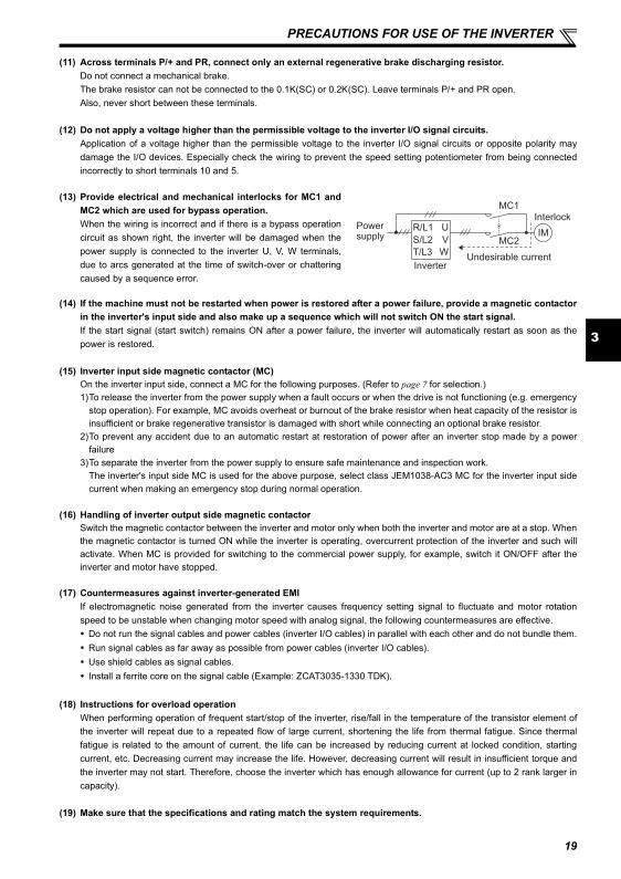
(13) Provide electrical and mechanical interlocks for MC1 andMC2 which are used for bypass operation. When the wiring is incorrect and if there is a bypass operationcircuit as shown right, the inverter will be damaged when thepower supply is connected to the inverter U, V, W terminals,due to arcs generated at the time of switch-over or chatteringcaused by a sequence error.
Power supply
InverterUndesirable current
MC2
MC1
InterlockU
V
W
R/L1
S/L2
T/L3
IM
19
20
FAILSAFE OF THE SYSTEM WHICH USES THE INVERTER
4 FAILSAFE OF THE SYSTEM WHICH USES THE INVERTERWhen a fault occurs, the inverter trips to output a fault signal. However, a fault output signal may not be output at an inverterfault occurrence when the detection circuit or output circuit fails, etc. Although Mitsubishi assures best quality products,provide an interlock which uses inverter status output signals to prevent accidents such as damage to machine when theinverter fails for some reason and at the same time consider the system configuration where failsafe from outside the inverter,without using the inverter, is enabled even if the inverter fails.
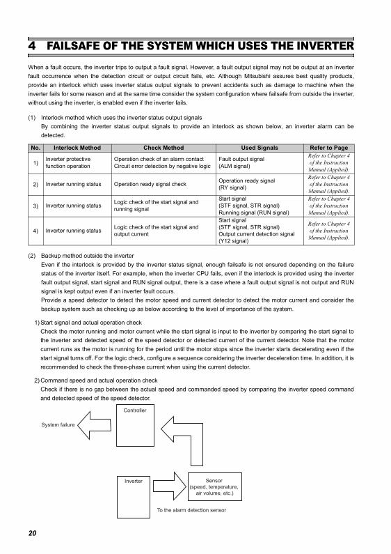
(1) Interlock method which uses the inverter status output signals By combining the inverter status output signals to provide an interlock as shown below, an inverter alarm can bedetected.
(2) Backup method outside the inverterEven if the interlock is provided by the inverter status signal, enough failsafe is not ensured depending on the failurestatus of the inverter itself. For example, when the inverter CPU fails, even if the interlock is provided using the inverterfault output signal, start signal and RUN signal output, there is a case where a fault output signal is not output and RUNsignal is kept output even if an inverter fault occurs.Provide a speed detector to detect the motor speed and current detector to detect the motor current and consider thebackup system such as checking up as below according to the level of importance of the system.
1) Start signal and actual operation checkCheck the motor running and motor current while the start signal is input to the inverter by comparing the start signal tothe inverter and detected speed of the speed detector or detected current of the current detector. Note that the motorcurrent runs as the motor is running for the period until the motor stops since the inverter starts decelerating even if thestart signal turns off. For the logic check, configure a sequence considering the inverter deceleration time. In addition, it isrecommended to check the three-phase current when using the current detector.
2) Command speed and actual operation checkCheck if there is no gap between the actual speed and commanded speed by comparing the inverter speed commandand detected speed of the speed detector.
No. Interlock Method Check Method Used Signals Refer to Page
1)Inverter protective function operation
Operation check of an alarm contactCircuit error detection by negative logic
Fault output signal (ALM signal)
Refer to Chapter 4 of the Instruction
Manual (Applied).
2) Inverter running status Operation ready signal check Operation ready signal (RY signal)
Refer to Chapter 4 of the Instruction
Manual (Applied).
3) Inverter running status Logic check of the start signal and running signal
Start signal (STF signal, STR signal)Running signal (RUN signal)
Refer to Chapter 4 of the Instruction
Manual (Applied).
4) Inverter running status Logic check of the start signal and output current
Start signal (STF signal, STR signal)Output current detection signal (Y12 signal)
Refer to Chapter 4 of the Instruction
Manual (Applied).
Inverter
Controller
System failure
To the alarm detection sensor
Sensor
(speed, temperature,
air volume, etc.)
Start/stop from the operation panel (PU operation)
5
4
5 DRIVING THE MOTOR
5.1 Start/stop from the operation panel (PU operation)
5.1.1 Setting the frequency by the operation panel
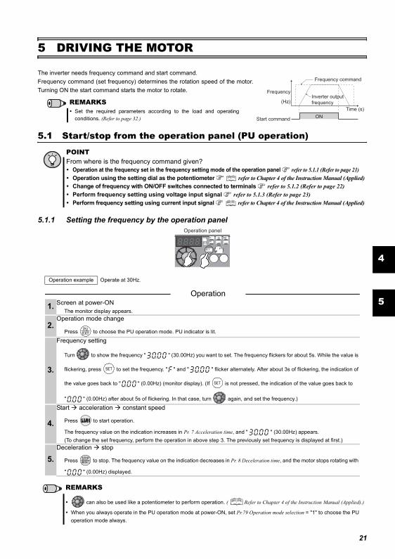
The inverter needs frequency command and start command. Frequency command (set frequency) determines the rotation speed of the motor.Turning ON the start command starts the motor to rotate.
POINTFrom where is the frequency command given?
Operation at the frequency set in the frequency setting mode of the operation panel refer to 5.1.1 (Refer to page 21)Operation using the setting dial as the potentiometer refer to Chapter 4 of the Instruction Manual (Applied)Change of frequency with ON/OFF switches connected to terminals refer to 5.1.2 (Refer to page 22) Perform frequency setting using voltage input signal refer to 5.1.3 (Refer to page 23) Perform frequency setting using current input signal refer to Chapter 4 of the Instruction Manual (Applied)
Operation example Operate at 30Hz.
Operation 1. Screen at power-ON
The monitor display appears.
2.Operation mode change
Press to choose the PU operation mode. PU indicator is lit.
3.
Frequency setting
Turn to show the frequency " " (30.00Hz) you want to set. The frequency flickers for about 5s. While the value is
flickering, press to set the frequency. " " and " " flicker alternately. After about 3s of flickering, the indication of
the value goes back to " " (0.00Hz) (monitor display). (If is not pressed, the indication of the value goes back to
" " (0.00Hz) after about 5s of flickering. In that case, turn again, and set the frequency.)
4.
Start acceleration constant speed
Press to start operation.
The frequency value on the indication increases in Pr. 7 Acceleration time, and " " (30.00Hz) appears.(To change the set frequency, perform the operation in above step 3. The previously set frequency is displayed at first.)
5.Deceleration stop
Press to stop. The frequency value on the indication decreases in Pr. 8 Deceleration time, and the motor stops rotating with
" " (0.00Hz) displayed.
REMARKS
can also be used like a potentiometer to perform operation. ( Refer to Chapter 4 of the Instruction Manual (Applied).)
When you always operate in the PU operation mode at power-ON, set Pr.79 Operation mode selection = "1" to choose the PU operation mode always.
REMARKSSet the required parameters according to the load and operatingconditions. (Refer to page 32.) ON
Frequency
Time (s)
(Hz)
Start command
Frequency command
Inverter output
frequency
Operation panel
21
Start/stop from the operation panel (PU operation)
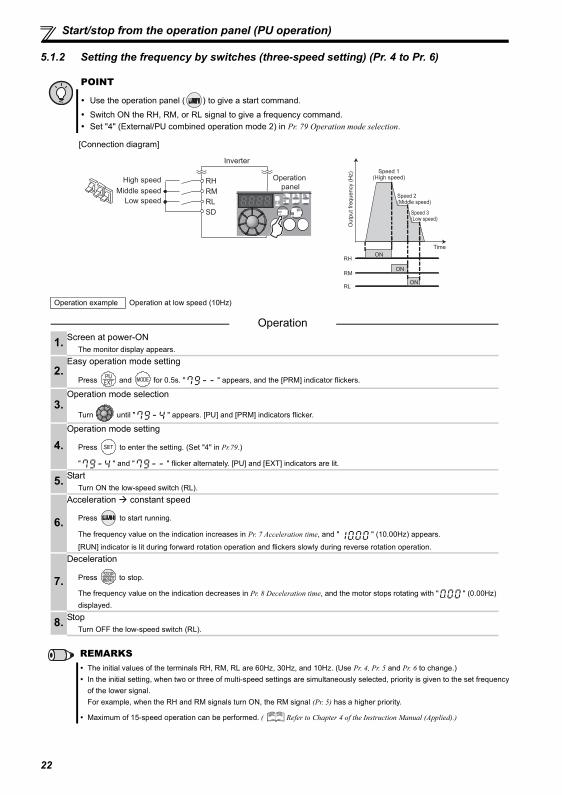
5.1.2 Setting the frequency by switches (three-speed setting) (Pr. 4 to Pr. 6)
POINT
Use the operation panel ( ) to give a start command.
Switch ON the RH, RM, or RL signal to give a frequency command.Set "4" (External/PU combined operation mode 2) in Pr. 79 Operation mode selection.
[Connection diagram]
Operation example Operation at low speed (10Hz)
Operation
1. Screen at power-ONThe monitor display appears.
2.Easy operation mode setting
Press and for 0.5s. " " appears, and the [PRM] indicator flickers.
3.Operation mode selection
Turn until " " appears. [PU] and [PRM] indicators flicker.
4.Operation mode setting
Press to enter the setting. (Set "4" in Pr.79.)
" " and " " flicker alternately. [PU] and [EXT] indicators are lit.
5. StartTurn ON the low-speed switch (RL).
6.
Acceleration constant speed
Press to start running.
The frequency value on the indication increases in Pr. 7 Acceleration time, and " " (10.00Hz) appears.
[RUN] indicator is lit during forward rotation operation and flickers slowly during reverse rotation operation.
7.
Deceleration
Press to stop.
The frequency value on the indication decreases in Pr. 8 Deceleration time, and the motor stops rotating with " " (0.00Hz) displayed.
8. StopTurn OFF the low-speed switch (RL).
REMARKSThe initial values of the terminals RH, RM, RL are 60Hz, 30Hz, and 10Hz. (Use Pr. 4, Pr. 5 and Pr. 6 to change.)In the initial setting, when two or three of multi-speed settings are simultaneously selected, priority is given to the set frequencyof the lower signal.For example, when the RH and RM signals turn ON, the RM signal (Pr. 5) has a higher priority.
Maximum of 15-speed operation can be performed. ( Refer to Chapter 4 of the Instruction Manual (Applied).)
SD
RH
RM
RL
Inverter
Operation
panelHigh speed
Middle speed
Low speed
ON
ON
ON
Ou
tpu
t fr
eq
ue
ncy (
Hz) Speed 1
(High speed)
Speed 2(Middle speed)
Speed 3(Low speed)
RH
RM
RL
Time
22
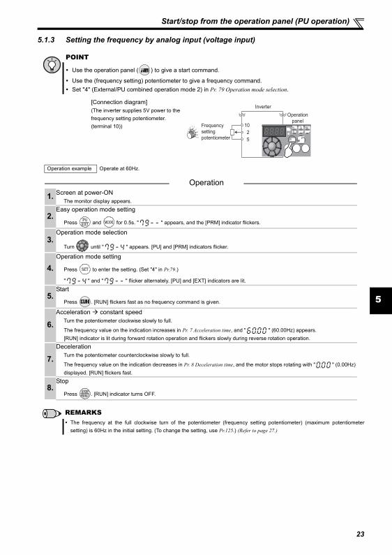
Start/stop from the operation panel (PU operation)
5
5.1.3 Setting the frequency by analog input (voltage input)
POINT
Use the operation panel ( ) to give a start command.
Use the (frequency setting) potentiometer to give a frequency command.Set "4" (External/PU combined operation mode 2) in Pr. 79 Operation mode selection.
[Connection diagram](The inverter supplies 5V power to the frequency setting potentiometer. (terminal 10))
Operation example Operate at 60Hz.
Operation
1. Screen at power-ONThe monitor display appears.
2.Easy operation mode setting
Press and for 0.5s. " " appears, and the [PRM] indicator flickers.
3.Operation mode selection
Turn until " " appears. [PU] and [PRM] indicators flicker.
4.Operation mode setting
Press to enter the setting. (Set "4" in Pr.79.)
" " and " " flicker alternately. [PU] and [EXT] indicators are lit.
5.Start
Press . [RUN] flickers fast as no frequency command is given.
6.Acceleration constant speed
Turn the potentiometer clockwise slowly to full.
The frequency value on the indication increases in Pr. 7 Acceleration time, and " " (60.00Hz) appears.[RUN] indicator is lit during forward rotation operation and flickers slowly during reverse rotation operation.
7.Deceleration
Turn the potentiometer counterclockwise slowly to full.
The frequency value on the indication decreases in Pr. 8 Deceleration time, and the motor stops rotating with " " (0.00Hz) displayed. [RUN] flickers fast.
8.Stop
Press . [RUN] indicator turns OFF.
REMARKSThe frequency at the full clockwise turn of the potentiometer (frequency setting potentiometer) (maximum potentiometersetting) is 60Hz in the initial setting. (To change the setting, use Pr.125.) (Refer to page 27.)
5
10
2
Frequency
setting
potentiometer
Inverter
Operation
panel
23
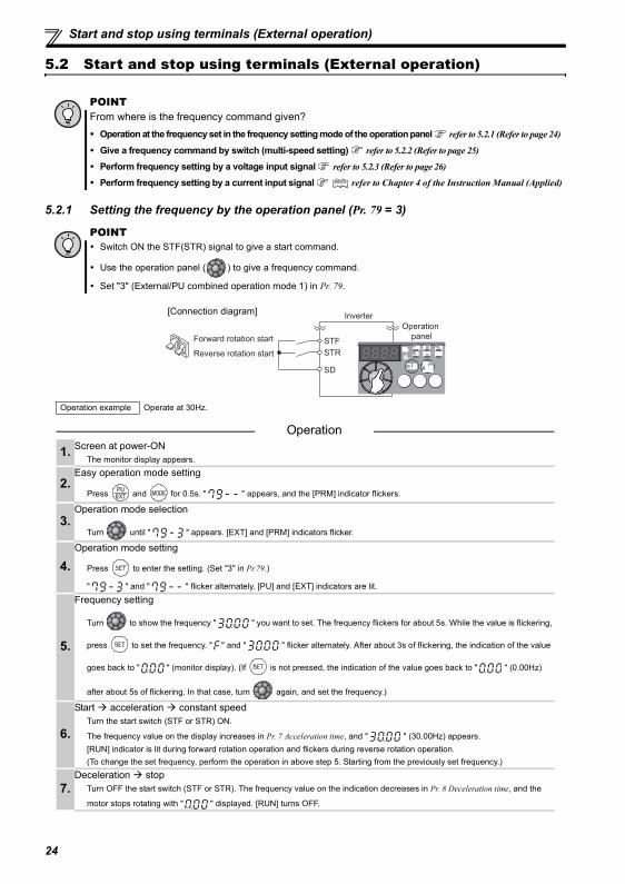
Start and stop using terminals (External operation)
5.2 Start and stop using terminals (External operation)
5.2.1 Setting the frequency by the operation panel (Pr. 79 = 3)
POINTFrom where is the frequency command given?
Operation at the frequency set in the frequency setting mode of the operation panel refer to 5.2.1 (Refer to page 24)
Give a frequency command by switch (multi-speed setting) refer to 5.2.2 (Refer to page 25)
Perform frequency setting by a voltage input signal refer to 5.2.3 (Refer to page 26)
Perform frequency setting by a current input signal refer to Chapter 4 of the Instruction Manual (Applied)
POINTSwitch ON the STF(STR) signal to give a start command.
Use the operation panel ( ) to give a frequency command.
Set "3" (External/PU combined operation mode 1) in Pr. 79.
Operation example Operate at 30Hz.
Operation
1. Screen at power-ONThe monitor display appears.
2.Easy operation mode setting
Press and for 0.5s. " " appears, and the [PRM] indicator flickers.
3.Operation mode selection
Turn until " " appears. [EXT] and [PRM] indicators flicker.
4.Operation mode setting
Press to enter the setting. (Set "3" in Pr.79.)
" " and " " flicker alternately. [PU] and [EXT] indicators are lit.
5.
Frequency setting
Turn to show the frequency " " you want to set. The frequency flickers for about 5s. While the value is flickering,
press to set the frequency. " " and " " flicker alternately. After about 3s of flickering, the indication of the value
goes back to " " (monitor display). (If is not pressed, the indication of the value goes back to " " (0.00Hz)
after about 5s of flickering. In that case, turn again, and set the frequency.)
6.
Start acceleration constant speedTurn the start switch (STF or STR) ON.
The frequency value on the display increases in Pr. 7 Acceleration time, and " " (30.00Hz) appears.[RUN] indicator is lit during forward rotation operation and flickers during reverse rotation operation.(To change the set frequency, perform the operation in above step 5. Starting from the previously set frequency.)
7.Deceleration stop
Turn OFF the start switch (STF or STR). The frequency value on the indication decreases in Pr. 8 Deceleration time, and the
motor stops rotating with " " displayed. [RUN] turns OFF.
SD
STF
STR
Inverter
Operation
panelForward rotation start
Reverse rotation start
[Connection diagram]
24
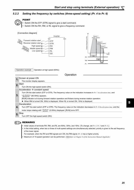
Start and stop using terminals (External operation)
5
5.2.2 Setting the frequency by switches (three-speed setting) (Pr. 4 to Pr. 6)
POINTSwitch ON the STF (STR) signal to give a start command.Switch ON the RH, RM, or RL signal to give a frequency command.
Operation example Operation at high speed (60Hz)
Operation
1. Screen at power-ONThe monitor display appears.
2. StartTurn ON the high-speed switch (RH).
3.
Acceleration constant speedTurn ON the start switch (STF or STR). The frequency value on the indication increases in Pr. 7 Acceleration time, and
" " (60.00Hz) appears.[RUN] indicator is lit during forward rotation operation and flickers during reverse rotation operation.
When RM is turned ON, 30Hz is displayed. When RL is turned ON, 10Hz is displayed.
4.Deceleration
Turn OFF the start switch (STF or STR). The frequency value on the indication decreases in Pr. 8 Deceleration time, and the
motor stops rotating with " " (0.00Hz) displayed. [RUN] turns OFF.
5. StopTurn OFF the high-speed switch (RH)
REMARKSInitial values of terminals RH, RM, and RL are 60Hz, 30Hz, and 10Hz. (To change, set Pr. 4, Pr. 5 and Pr. 6.)In the initial setting, when two or three of multi-speed settings are simultaneously selected, priority is given to the set frequencyof the lower signal.For example, when the RH and RM signals turn ON, the RM signal (Pr. 5) has a higher priority.Maximum of 15-speed operation can be performed. ( Refer to Chapter 4 of the Instruction Manual (Applied).)
Inverter
Forward rotation startReverse rotation start
High speedRM
STFSTRRH
Middle speedLow speed
SDRL
[Connection diagram]
ON
ON
ON
Ou
tpu
t fr
eq
ue
ncy (
Hz) Speed 1
(High speed)
Speed 2(Middle speed)
Speed 3(Low speed)
RH
RM
RL
Time
25
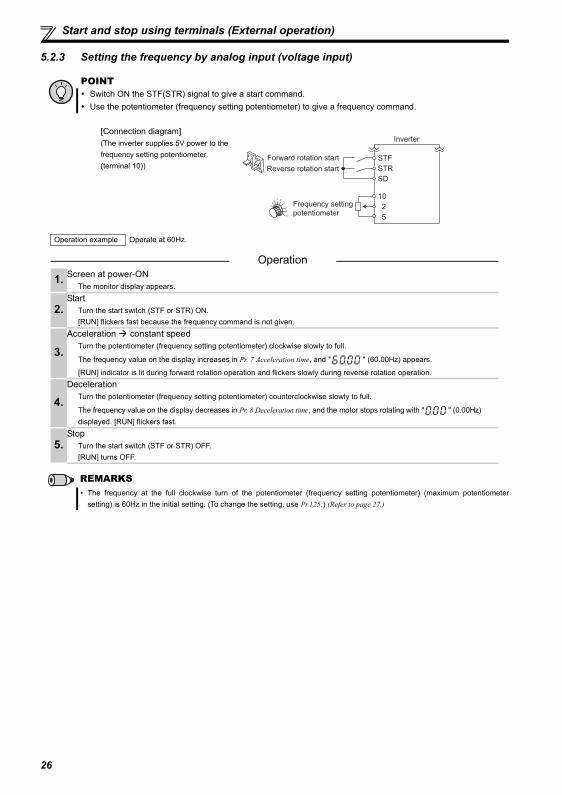
Start and stop using terminals (External operation)
5.2.3 Setting the frequency by analog input (voltage input)
POINTSwitch ON the STF(STR) signal to give a start command.Use the potentiometer (frequency setting potentiometer) to give a frequency command.
[Connection diagram](The inverter supplies 5V power to the frequency setting potentiometer. (terminal 10))
Operation example Operate at 60Hz.
Operation
1. Screen at power-ONThe monitor display appears.
2.Start
Turn the start switch (STF or STR) ON.[RUN] flickers fast because the frequency command is not given.
3.Acceleration constant speed
Turn the potentiometer (frequency setting potentiometer) clockwise slowly to full.
The frequency value on the display increases in Pr. 7 Acceleration time, and " " (60.00Hz) appears.
[RUN] indicator is lit during forward rotation operation and flickers slowly during reverse rotation operation.
4.Deceleration
Turn the potentiometer (frequency setting potentiometer) counterclockwise slowly to full.
The frequency value on the display decreases in Pr. 8 Deceleration time, and the motor stops rotating with " " (0.00Hz) displayed. [RUN] flickers fast.
5.Stop
Turn the start switch (STF or STR) OFF. [RUN] turns OFF.
REMARKSThe frequency at the full clockwise turn of the potentiometer (frequency setting potentiometer) (maximum potentiometersetting) is 60Hz in the initial setting. (To change the setting, use Pr.125.) (Refer to page 27.)
Frequency setting
potentiometer
Inverter
5
10
2
Forward rotation start
Reverse rotation start
STF
STR
SD
26
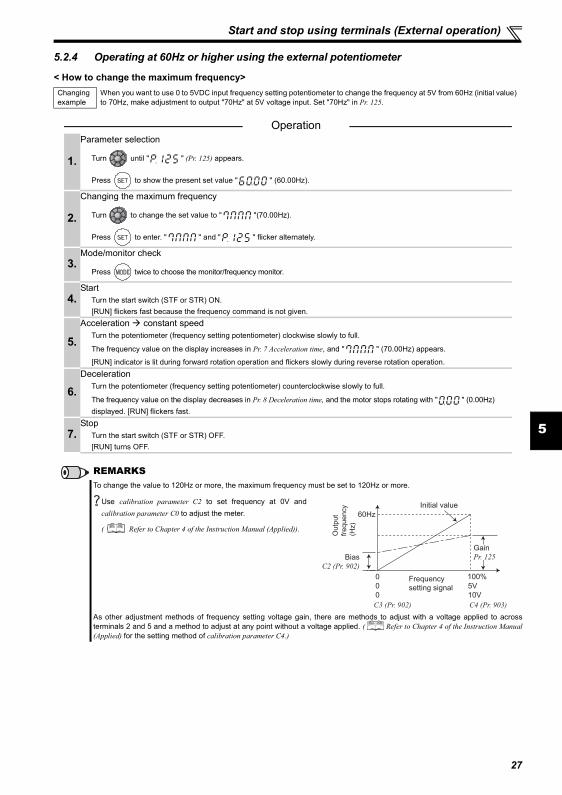
Start and stop using terminals (External operation)
5
5.2.4 Operating at 60Hz or higher using the external potentiometer
< How to change the maximum frequency>Changing example
When you want to use 0 to 5VDC input frequency setting potentiometer to change the frequency at 5V from 60Hz (initial value) to 70Hz, make adjustment to output "70Hz" at 5V voltage input. Set "70Hz" in Pr. 125.
Operation
1.
Parameter selection
Turn until " " (Pr. 125) appears.
Press to show the present set value " " (60.00Hz).
2.
Changing the maximum frequency
Turn to change the set value to " "(70.00Hz).
Press to enter. " " and " " flicker alternately.
3.Mode/monitor check
Press twice to choose the monitor/frequency monitor.
4.Start
Turn the start switch (STF or STR) ON.[RUN] flickers fast because the frequency command is not given.
5.Acceleration constant speed
Turn the potentiometer (frequency setting potentiometer) clockwise slowly to full.
The frequency value on the display increases in Pr. 7 Acceleration time, and " " (70.00Hz) appears.
[RUN] indicator is lit during forward rotation operation and flickers slowly during reverse rotation operation.
6.Deceleration
Turn the potentiometer (frequency setting potentiometer) counterclockwise slowly to full.
The frequency value on the display decreases in Pr. 8 Deceleration time, and the motor stops rotating with " " (0.00Hz) displayed. [RUN] flickers fast.
7.Stop
Turn the start switch (STF or STR) OFF. [RUN] turns OFF.
REMARKSTo change the value to 120Hz or more, the maximum frequency must be set to 120Hz or more.
Use calibration parameter C2 to set frequency at 0V andcalibration parameter C0 to adjust the meter.
( Refer to Chapter 4 of the Instruction Manual (Applied)).
As other adjustment methods of frequency setting voltage gain, there are methods to adjust with a voltage applied to acrossterminals 2 and 5 and a method to adjust at any point without a voltage applied. ( Refer to Chapter 4 of the Instruction Manual(Applied) for the setting method of calibration parameter C4.)
Initial value
Bias
C2 (Pr. 902)
0
0
Frequency
setting signal
100%
10V
0 5V
C3 (Pr. 902) C4 (Pr. 903)
Gain
Pr. 125
Outp
ut
frequency
(Hz)
60Hz
27
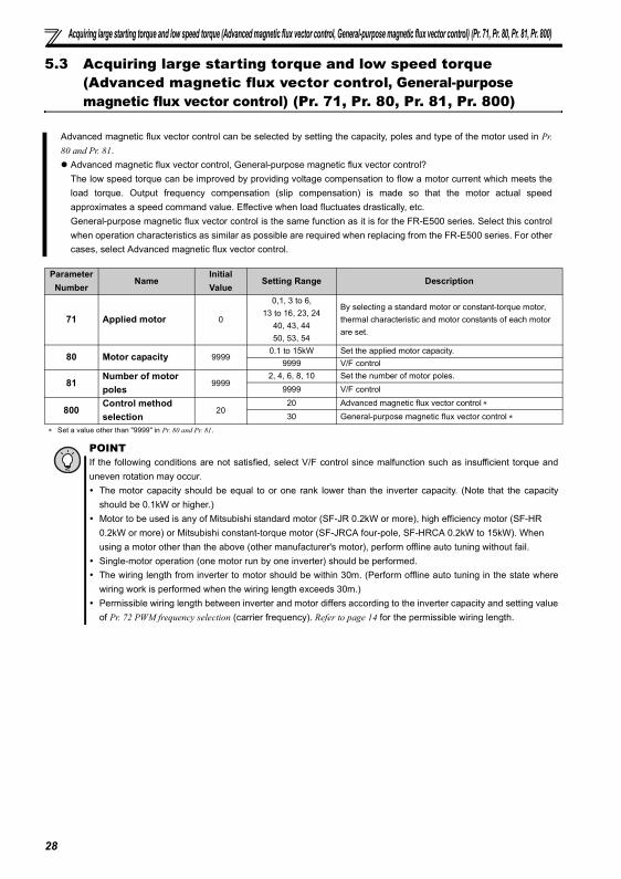
Acquiring large starting torque and low speed torque (Advanced magnetic flux vector control, General-purpose magnetic flux vector control) (Pr. 71, Pr. 80, Pr. 81, Pr. 800)
5.3 Acquiring large starting torque and low speed torque (Advanced magnetic flux vector control, General-purpose magnetic flux vector control) (Pr. 71, Pr. 80, Pr. 81, Pr. 800)
Advanced magnetic flux vector control can be selected by setting the capacity, poles and type of the motor used in Pr.80 and Pr. 81.
Advanced magnetic flux vector control, General-purpose magnetic flux vector control?The low speed torque can be improved by providing voltage compensation to flow a motor current which meets theload torque. Output frequency compensation (slip compensation) is made so that the motor actual speedapproximates a speed command value. Effective when load fluctuates drastically, etc.General-purpose magnetic flux vector control is the same function as it is for the FR-E500 series. Select this controlwhen operation characteristics as similar as possible are required when replacing from the FR-E500 series. For othercases, select Advanced magnetic flux vector control.
Parameter Number
NameInitial Value
Setting Range Description
71 Applied motor 0
0,1, 3 to 6,13 to 16, 23, 24
40, 43, 4450, 53, 54
By selecting a standard motor or constant-torque motor, thermal characteristic and motor constants of each motor are set.
80 Motor capacity 99990.1 to 15kW Set the applied motor capacity.
9999 V/F control
81Number of motor poles
99992, 4, 6, 8, 10 Set the number of motor poles.
9999 V/F control
800Control method selection
2020 Advanced magnetic flux vector control ∗30 General-purpose magnetic flux vector control ∗
∗ Set a value other than "9999" in Pr. 80 and Pr. 81.
POINTIf the following conditions are not satisfied, select V/F control since malfunction such as insufficient torque anduneven rotation may occur.
The motor capacity should be equal to or one rank lower than the inverter capacity. (Note that the capacityshould be 0.1kW or higher.)Motor to be used is any of Mitsubishi standard motor (SF-JR 0.2kW or more), high efficiency motor (SF-HR 0.2kW or more) or Mitsubishi constant-torque motor (SF-JRCA four-pole, SF-HRCA 0.2kW to 15kW). When using a motor other than the above (other manufacturer's motor), perform offline auto tuning without fail.Single-motor operation (one motor run by one inverter) should be performed.The wiring length from inverter to motor should be within 30m. (Perform offline auto tuning in the state wherewiring work is performed when the wiring length exceeds 30m.)Permissible wiring length between inverter and motor differs according to the inverter capacity and setting valueof Pr. 72 PWM frequency selection (carrier frequency). Refer to page 14 for the permissible wiring length.
28
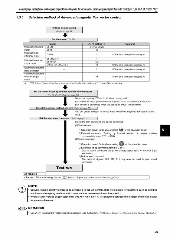
Acquiring large starting torque and low speed torque (Advanced magnetic flux vector control, General-purpose magnetic flux vector control) (Pr. 71, Pr. 80, Pr. 81, Pr. 800)
5
5.3.1 Selection method of Advanced magnetic flux vector control
Perform secure wiring.(Refer to page 9)
Set the motor. (Pr. 71)
Motor Pr. 71 Setting ∗1 RemarksMitsubishi standard motorMitsubishi high efficiency motor
SF-JR 0 (initial value)SF-HR 40
Others 3 Offline auto tuning is necessary. ∗1
Mitsubishi constant-torque motor
SF-JRCA 4P 1SF-HRCA 50Others (SF-JRC, etc.) 13 Offline auto tuning is necessary. ∗1
Other manufacturer's standard motor
— 3 Offline auto tuning is necessary. ∗1
Other manufacturer's constant-torque motor
— 13 Offline auto tuning is necessary. ∗1
∗1 Refer to Chapter 4 of the Instruction Manual (Applied) for other settings of Pr. 71 and offline auto tuning.
Set the motor capacity and the number of motor poles. (Pr. 80, Pr. 81) (Refer to page 28)
Set motor capacity (kW) in Pr. 80 Motor capacity and the number of motor poles (number of poles) in Pr. 81 Number of motor poles.(V/F control is performed when the setting is "9999" (initial value).
Select the control method. (Pr. 800) (Refer to page 28)Set "20" (initial value) in Pr. 800 to make Advanced magnetic flux vector control valid.
Set the operation command. (Refer to page 21)Select the start command and speed command.(1)Start command
1)Operation panel: Setting by pressing of the operation panel2)External command: Setting by forward rotation or reverse rotation
command (terminal STF or STR)(2)Speed command
1)Operation panel: Setting by pressing of the operation panel2)External analog command (terminal 2 or 4):
Give a speed command using the analog signal input to terminal 2 (orterminal 4).
3)Multi-speed command:The external signals (RH, RM, RL) may also be used to give speedcommand.
Test runAs required Perform offline auto tuning. (Pr. 96) ( Refer to Chapter 4 of the Instruction Manual (Applied))
NOTEUneven rotation slightly increases as compared to the V/F control. (It is not suitable for machines such as grindingmachine and wrapping machine which requires less uneven rotation at low speed.)When a surge voltage suppression filter (FR-ASF-H/FR-BMF-H) is connected between the inverter and motor, outputtorque may decrease.
REMARKSUse Pr. 89 to adjust the motor speed fluctuation at load fluctuation. ( Refer to Chapter 4 of the Instruction Manual (Applied).)
29
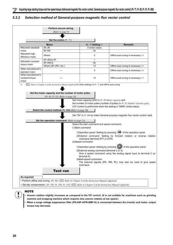
Acquiring large starting torque and low speed torque (Advanced magnetic flux vector control, General-purpose magnetic flux vector control) (Pr. 71, Pr. 80, Pr. 81, Pr. 800)
5.3.2 Selection method of General-purpose magnetic flux vector control
Perform secure wiring.(Refer to page 9)
Set the motor.(Pr. 71)
Motor Pr. 71 Setting ∗1 RemarksMitsubishi standard motorMitsubishi high efficiency motor
SF-JR 0 (initial value)SF-HR 40
Others 3 Offline auto tuning is necessary. ∗1
Mitsubishi constant-torque motor
SF-JRCA 4P 1SF-HRCA 50Others (SF-JRC, etc.) 13 Offline auto tuning is necessary. ∗1
Other manufacturer's standard motor
— 3 Offline auto tuning is necessary. ∗1
Other manufacturer's constant-torque motor
— 13 Offline auto tuning is necessary. ∗1
∗1 Refer to Chapter 4 of the Instruction Manual (Applied) for other settings of Pr. 71 and offline auto tuning.
Set the motor capacity and the number of motor poles.(Pr. 80, Pr. 81) (Refer to page 28)
Set motor capacity (kW) in Pr. 80 Motor capacity and the number of motor poles (number of poles) in Pr. 81 Number of motor poles.(V/F control is performed when the setting is "9999" (initial value).
Select the control method.(Pr. 800) (Refer to page 28)
Set "30" in Pr. 800 to make General-purpose magnetic flux vector control valid.
Set the operation command. (Refer to page 21)Select the start command and speed command.(1)Start command
1)Operation panel: Setting by pressing of the operation panel2)External command: Setting by forward rotation or reverse rotation
command (terminal STF or STR)(2)Speed command
1)Operation panel: Setting by pressing of the operation panel2)External analog command (terminal 2 or 4):
Give a speed command using the analog signal input to terminal 2 (orterminal 4).
3)Multi-speed command:The external signals (RH, RM, RL) may also be used to give speedcommand.
Test runAs required Perform offline auto tuning. (Pr. 96) ( Refer to Chapter 4 of the Instruction Manual (Applied))
Set slip compensation. (Pr. 245, Pr. 246, Pr. 247) ( Refer to Chapter 4 of the Instruction Manual (Applied))
NOTEUneven rotation slightly increases as compared to the V/F control. (It is not suitable for machines such as grindingmachine and wrapping machine which requires less uneven rotation at low speed.)When a surge voltage suppression filter (FR-ASF-H/FR-BMF-H) is connected between the inverter and motor, outputtorque may decrease.
30
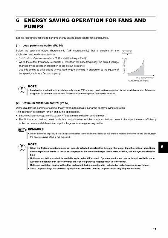
31
ENERGY SAVING OPERATION FOR FANS AND PUMPS
6
6 ENERGY SAVING OPERATION FOR FANS AND PUMPS
Set the following functions to perform energy saving operation for fans and pumps.
(1) Load pattern selection (Pr. 14)
Select the optimum output characteristic (V/F characteristic) that is suitable for theapplication and load characteristics.
Set Pr.14 Load pattern selection = "1 (for variable-torque load)."When the output frequency is equal to or less than the base frequency, the output voltagechanges by its square in proportion to the output frequency.Use this setting to drive a load whose load torque changes in proportion to the square ofthe speed, such as a fan and a pump.
(2) Optimum excitation control (Pr. 60)
Without a detailed parameter setting, the inverter automatically performs energy saving operation.This operation is optimum for fan and pump applications.
Set Pr.60 Energy saving control selection = "9 (optimum excitation control mode)."The Optimum excitation control mode is a control system which controls excitation current to improve the motor efficiencyto the maximum and determines output voltage as an energy saving method.
NOTELoad pattern selection is available only under V/F control. Load pattern selection is not available under Advancedmagnetic flux vector control and General-purpose magnetic flux vector control.
REMARKSWhen the motor capacity is too small as compared to the inverter capacity or two or more motors are connected to one inverter,the energy saving effect is not expected.
NOTEWhen the Optimum excitation control mode is selected, deceleration time may be longer than the setting value. Sinceovervoltage alarm tends to occur as compared to the constant-torque load characteristics, set a longer decelerationtime.Optimum excitation control is available only under V/F control. Optimum excitation control is not available underAdvanced magnetic flux vector control and General-purpose magnetic flux vector control.Optimum excitation control will not be performed during an automatic restart after instantaneous power failure. Since output voltage is controlled by Optimum excitation control, output current may slightly increase.
100%
Outp
ut voltage
Pr. 3 Base frequency
Output frequency (Hz)
Pr. 14 = 1
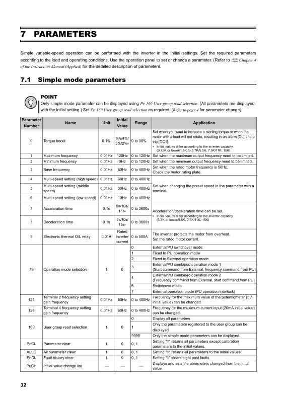
Simple mode parameters
7 PARAMETERS
Simple variable-speed operation can be performed with the inverter in the initial settings. Set the required parametersaccording to the load and operating conditions. Use the operation panel to set or change a parameter. (Refer to Chapter 4of the Instruction Manual (Applied) for the detailed description of parameters.
7.1 Simple mode parameters
POINTOnly simple mode parameter can be displayed using Pr. 160 User group read selection. (All parameters are displayedwith the initial setting.) Set Pr. 160 User group read selection as required. (Refer to page 4 for parameter change)
Parameter Number
Name UnitInitial Value
Range Application
0 Torque boost 0.1% 6%/4%/3%/2%∗
0 to 30%
Set when you want to increase a starting torque or when the motor with a load will not rotate, resulting in an alarm [OL] and a trip [OC1].∗ Initial values differ according to the inverter capacity.
(0.75K or lower/1.5K to 3.7K/5.5K, 7.5K/11K, 15K)
1 Maximum frequency 0.01Hz 120Hz 0 to 120Hz Set when the maximum output frequency need to be limited.2 Minimum frequency 0.01Hz 0Hz 0 to 120Hz Set when the minimum output frequency need to be limited.
3 Base frequency 0.01Hz 60Hz 0 to 400Hz Set when the rated motor frequency is 50Hz.Check the motor rating plate.
4 Multi-speed setting (high speed) 0.01Hz 60Hz 0 to 400Hz
Set when changing the preset speed in the parameter with a terminal.5 Multi-speed setting (middle
speed) 0.01Hz 30Hz 0 to 400Hz
6 Multi-speed setting (low speed) 0.01Hz 10Hz 0 to 400Hz
7 Acceleration time 0.1s 5s/10s/15s∗
0 to 3600sAcceleration/deceleration time can be set.∗ Initial values differ according to the inverter capacity.
(3.7K or lower/5.5K, 7.5K/11K, 15K)8 Deceleration time 0.1s 5s/10s/15s∗
0 to 3600s
9 Electronic thermal O/L relay 0.01ARated
inverter current
0 to 500A The inverter protects the motor from overheat.Set the rated motor current.
79 Operation mode selection 1 0
0 External/PU switchover mode1 Fixed to PU operation mode2 Fixed to External operation mode
3 External/PU combined operation mode 1(Start command from External, frequency command from PU)
4 External/PU combined operation mode 2(Frequency command from External, start command from PU)
6 Switchover mode7 External operation mode (PU operation interlock)
125 Terminal 2 frequency setting gain frequency 0.01Hz 60Hz 0 to 400Hz Frequency for the maximum value of the potentiometer (5V
initial value) can be changed.
126 Terminal 4 frequency setting gain frequency 0.01Hz 60Hz 0 to 400Hz Frequency for the maximum current input (20mA initial value)
can be changed.
160 User group read selection 1 0
0 Display all parameters
1Only the parameters registered to the user group can be displayed.
9999 Only the simple mode parameters can be displayed.
Pr.CL Parameter clear 1 0 0, 1 Setting "1" returns all parameters except calibration parameters to the initial values.
ALLC All parameter clear 1 0 0, 1 Setting "1" returns all parameters to the initial values.Er.CL Fault history clear 1 0 0, 1 Setting "1" clears eight past faults.
Pr.CH Initial value change list Displays and sets the parameters changed from the initial value.
32
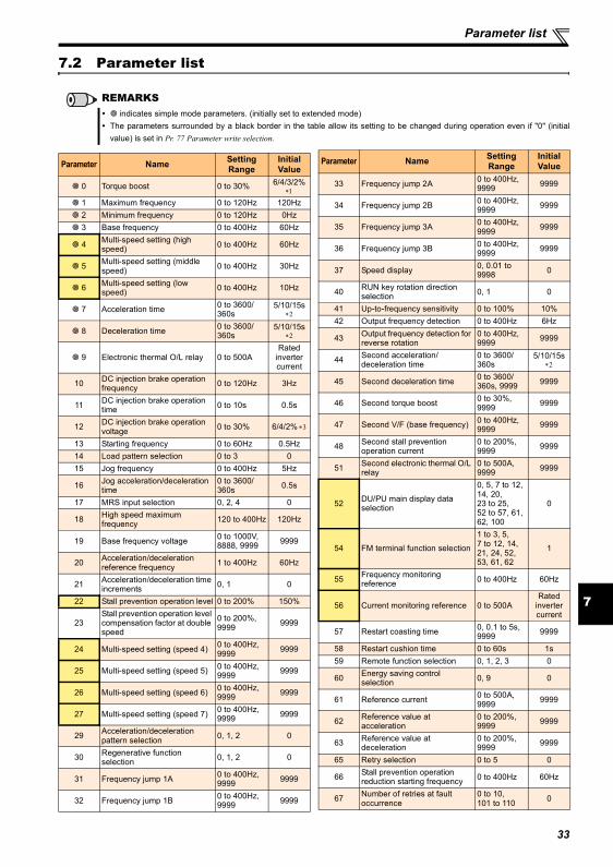
7
Parameter list
7.2 Parameter list
REMARKS indicates simple mode parameters. (initially set to extended mode)
The parameters surrounded by a black border in the table allow its setting to be changed during operation even if "0" (initialvalue) is set in Pr. 77 Parameter write selection.
Parameter Name Setting Range
Initial Value
0 Torque boost 0 to 30% 6/4/3/2% ∗1
1 Maximum frequency 0 to 120Hz 120Hz 2 Minimum frequency 0 to 120Hz 0Hz 3 Base frequency 0 to 400Hz 60Hz
4 Multi-speed setting (high speed) 0 to 400Hz 60Hz
5 Multi-speed setting (middle speed) 0 to 400Hz 30Hz
6 Multi-speed setting (low speed) 0 to 400Hz 10Hz
7 Acceleration time 0 to 3600/360s
5/10/15s ∗2
8 Deceleration time 0 to 3600/360s
5/10/15s ∗2
9 Electronic thermal O/L relay 0 to 500ARated
inverter current
10 DC injection brake operation frequency 0 to 120Hz 3Hz
11 DC injection brake operation time 0 to 10s 0.5s
12 DC injection brake operation voltage 0 to 30% 6/4/2% ∗3
13 Starting frequency 0 to 60Hz 0.5Hz14 Load pattern selection 0 to 3 015 Jog frequency 0 to 400Hz 5Hz
16 Jog acceleration/deceleration time
0 to 3600/360s 0.5s
17 MRS input selection 0, 2, 4 0
18 High speed maximum frequency 120 to 400Hz 120Hz
19 Base frequency voltage 0 to 1000V, 8888, 9999 9999
20 Acceleration/deceleration reference frequency 1 to 400Hz 60Hz
21 Acceleration/deceleration time increments 0, 1 0
22 Stall prevention operation level 0 to 200% 150%
23Stall prevention operation level compensation factor at double speed
0 to 200%, 9999 9999
24 Multi-speed setting (speed 4) 0 to 400Hz, 9999 9999
25 Multi-speed setting (speed 5) 0 to 400Hz, 9999 9999
26 Multi-speed setting (speed 6) 0 to 400Hz, 9999 9999
27 Multi-speed setting (speed 7) 0 to 400Hz, 9999 9999
29 Acceleration/deceleration pattern selection 0, 1, 2 0
30 Regenerative function selection 0, 1, 2 0
31 Frequency jump 1A 0 to 400Hz, 9999 9999
32 Frequency jump 1B 0 to 400Hz, 9999 9999
33 Frequency jump 2A 0 to 400Hz, 9999 9999
34 Frequency jump 2B 0 to 400Hz, 9999 9999
35 Frequency jump 3A 0 to 400Hz, 9999 9999
36 Frequency jump 3B 0 to 400Hz, 9999 9999
37 Speed display 0, 0.01 to 9998 0
40 RUN key rotation direction selection 0, 1 0
41 Up-to-frequency sensitivity 0 to 100% 10%42 Output frequency detection 0 to 400Hz 6Hz
43 Output frequency detection for reverse rotation
0 to 400Hz, 9999 9999
44 Second acceleration/deceleration time
0 to 3600/360s
5/10/15s ∗2
45 Second deceleration time 0 to 3600/360s, 9999 9999
46 Second torque boost 0 to 30%, 9999 9999
47 Second V/F (base frequency) 0 to 400Hz, 9999 9999
48 Second stall prevention operation current
0 to 200%, 9999 9999
51 Second electronic thermal O/L relay
0 to 500A, 9999 9999
52 DU/PU main display data selection
0, 5, 7 to 12, 14, 20, 23 to 25, 52 to 57, 61, 62, 100
0
54 FM terminal function selection
1 to 3, 5, 7 to 12, 14, 21, 24, 52, 53, 61, 62
1
55 Frequency monitoring reference 0 to 400Hz 60Hz
56 Current monitoring reference 0 to 500ARated
inverter current
57 Restart coasting time 0, 0.1 to 5s, 9999 9999
58 Restart cushion time 0 to 60s 1s59 Remote function selection 0, 1, 2, 3 0
60 Energy saving control selection 0, 9 0
61 Reference current 0 to 500A, 9999 9999
62 Reference value at acceleration
0 to 200%, 9999 9999
63 Reference value at deceleration
0 to 200%, 9999 9999
65 Retry selection 0 to 5 0
66 Stall prevention operation reduction starting frequency 0 to 400Hz 60Hz
67 Number of retries at fault occurrence
0 to 10, 101 to 110 0
Parameter Name Setting Range
Initial Value
33
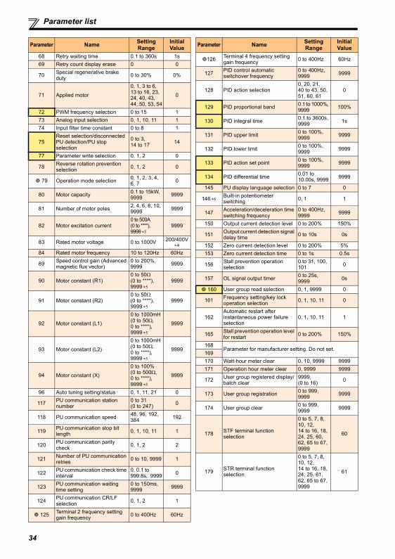
Parameter list
68 Retry waiting time 0.1 to 360s 1s69 Retry count display erase 0 0
70 Special regenerative brake duty 0 to 30% 0%
71 Applied motor
0, 1, 3 to 6, 13 to 16, 23, 24, 40, 43, 44, 50, 53, 54
0
72 PWM frequency selection 0 to 15 173 Analog input selection 0, 1, 10, 11 174 Input filter time constant 0 to 8 1
75Reset selection/disconnected PU detection/PU stop selection
0 to 3, 14 to 17 14
77 Parameter write selection 0, 1, 2 0
78 Reverse rotation prevention selection 0, 1, 2 0
79 Operation mode selection 0, 1, 2, 3, 4, 6, 7 0
80 Motor capacity 0.1 to 15kW, 9999 9999
81 Number of motor poles 2, 4, 6, 8, 10, 9999 9999
82 Motor excitation current0 to 500A (0 to ****), 9999 ∗5
9999
83 Rated motor voltage 0 to 1000V 200/400V ∗4
84 Rated motor frequency 10 to 120Hz 60Hz
89 Speed control gain (Advanced magnetic flux vector)
0 to 200%, 9999 9999
90 Motor constant (R1)0 to 50Ω (0 to ****), 9999 ∗5
9999
91 Motor constant (R2)0 to 50Ω (0 to ****), 9999 ∗5
9999
92 Motor constant (L1)
0 to 1000mH (0 to 50Ω, 0 to ****), 9999 ∗5
9999
93 Motor constant (L2)
0 to 1000mH (0 to 50Ω, 0 to ****), 9999 ∗5
9999
94 Motor constant (X)
0 to 100% (0 to 500Ω, 0 to ****), 9999 ∗5
9999
96 Auto tuning setting/status 0, 1, 11, 21 0
117 PU communication station number
0 to 31 (0 to 247) 0
118 PU communication speed 48, 96, 192, 384 192
119 PU communication stop bit length 0, 1, 10, 11 1
120 PU communication parity check 0, 1, 2 2
121 Number of PU communication retries 0 to 10, 9999 1
122 PU communication check time interval
0, 0.1 to 999.8s, 9999 0
123 PU communication waiting time setting
0 to 150ms, 9999 9999
124 PU communication CR/LF selection 0, 1, 2 1
125 Terminal 2 frequency setting gain frequency 0 to 400Hz 60Hz
Parameter Name Setting Range
Initial Value
126 Terminal 4 frequency setting gain frequency 0 to 400Hz 60Hz
127 PID control automatic switchover frequency
0 to 400Hz, 9999 9999
128 PID action selection0, 20, 21, 40 to 43, 50, 51, 60, 61
0
129 PID proportional band 0.1 to 1000%, 9999 100%
130 PID integral time 0.1 to 3600s, 9999 1s
131 PID upper limit 0 to 100%, 9999 9999
132 PID lower limit 0 to 100%, 9999 9999
133 PID action set point 0 to 100%, 9999 9999
134 PID differential time 0.01 to 10.00s, 9999 9999
145 PU display language selection 0 to 7 0
146 ∗6Built-in potentiometer switching 0, 1 1
147 Acceleration/deceleration time switching frequency
0 to 400Hz, 9999 9999
150 Output current detection level 0 to 200% 150%
151 Output current detection signal delay time 0 to 10s 0s
152 Zero current detection level 0 to 200% 5%153 Zero current detection time 0 to 1s 0.5s
156 Stall prevention operation selection
0 to 31, 100, 101 0
157 OL signal output timer 0 to 25s, 9999 0s
160 User group read selection 0, 1, 9999 0
161 Frequency setting/key lock operation selection 0, 1, 10, 11 0
162Automatic restart after instantaneous power failure selection
0, 1, 10, 11 1
165 Stall prevention operation level for restart 0 to 200% 150%
168Parameter for manufacturer setting. Do not set.
169170 Watt-hour meter clear 0, 10, 9999 9999171 Operation hour meter clear 0, 9999 9999
172 User group registered display/batch clear
9999, (0 to 16) 0
173 User group registration 0 to 999, 9999 9999
174 User group clear 0 to 999, 9999 9999
178 STF terminal function selection
0 to 5, 7, 8, 10, 12, 14 to 16, 18, 24, 25, 60, 62, 65 to 67, 9999
60
179 STR terminal function selection
0 to 5, 7, 8, 10, 12, 14 to 16, 18, 24, 25, 61, 62, 65 to 67, 9999
61
Parameter Name Setting Range
Initial Value
34
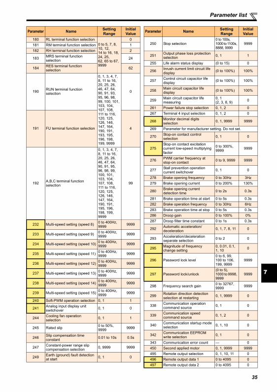
7
Parameter list
180 RL terminal function selection0 to 5, 7, 8, 10, 12, 14 to 16, 18, 24, 25, 62, 65 to 67, 9999
0181 RM terminal function selection 1182 RH terminal function selection 2
183 MRS terminal function selection 24
184 RES terminal function selection 62
190 RUN terminal function selection
0, 1, 3, 4, 7, 8, 11 to 16, 20, 25, 26, 46, 47, 64, 90, 91, 93, 95, 96, 98, 99, 100, 101, 103, 104, 107, 108, 111 to 116, 120, 125, 126, 146, 147, 164, 190, 191, 193, 195, 196, 198, 199, 9999
0
191 FU terminal function selection 4
192 A,B,C terminal function selection
0, 1, 3, 4, 7, 8, 11 to 16, 20, 25, 26, 46, 47, 64, 90, 91, 95, 96, 98, 99, 100, 101, 103, 104, 107, 108, 111 to 116, 120, 125, 126, 146, 147, 164, 190, 191, 195, 196, 198, 199, 9999
99
232 Multi-speed setting (speed 8) 0 to 400Hz, 9999 9999
233 Multi-speed setting (speed 9) 0 to 400Hz, 9999 9999
234 Multi-speed setting (speed 10) 0 to 400Hz, 9999 9999
235 Multi-speed setting (speed 11) 0 to 400Hz, 9999 9999
236 Multi-speed setting (speed 12) 0 to 400Hz, 9999 9999
237 Multi-speed setting (speed 13) 0 to 400Hz, 9999 9999
238 Multi-speed setting (speed 14) 0 to 400Hz, 9999 9999
239 Multi-speed setting (speed 15) 0 to 400Hz, 9999 9999
240 Soft-PWM operation selection 0, 1 1
241 Analog input display unit switchover 0, 1 0
244 Cooling fan operation selection 0, 1 1
245 Rated slip 0 to 50%, 9999 9999
246 Slip compensation time constant 0.01 to 10s 0.5s
247 Constant-power range slip compensation selection 0, 9999 9999
249 Earth (ground) fault detection at start 0, 1 0
Parameter Name Setting Range
Initial Value
250 Stop selection0 to 100s, 1000 to 1100s, 8888, 9999
9999
251 Output phase loss protection selection 0, 1 1
255 Life alarm status display (0 to 15) 0
256 Inrush current limit circuit life display (0 to 100%) 100%
257 Control circuit capacitor life display (0 to 100%) 100%
258 Main circuit capacitor life display (0 to 100%) 100%
259 Main circuit capacitor life measuring
0, 1 (2, 3, 8, 9) 0
261 Power failure stop selection 0, 1, 2 0267 Terminal 4 input selection 0, 1, 2 0
268 Monitor decimal digits selection 0, 1, 9999 9999
269 Parameter for manufacturer setting. Do not set.
270 Stop-on contact control selection 0, 1 0
275Stop-on contact excitation current low-speed multiplying factor
0 to 300%, 9999 9999
276 PWM carrier frequency at stop-on contact 0 to 9, 9999 9999
277 Stall prevention operation current switchover 0, 1 0
278 Brake opening frequency 0 to 30Hz 3Hz279 Brake opening current 0 to 200% 130%
280 Brake opening current detection time 0 to 2s 0.3s
281 Brake operation time at start 0 to 5s 0.3s282 Brake operation frequency 0 to 30Hz 6Hz283 Brake operation time at stop 0 to 5s 0.3s286 Droop gain 0 to 100% 0%287 Droop filter time constant 0 to 1s 0.3s
292 Automatic acceleration/deceleration 0, 1, 7, 8, 11 0
293 Acceleration/deceleration separate selection 0 to 2 0
295 Magnitude of frequency change setting
0, 0.01, 0.1, 1, 10 0
296 Password lock level0 to 6, 99, 100 to 106, 199, 9999
9999
297 Password lock/unlock(0 to 5), 1000 to 9998, 9999
9999
298 Frequency search gain 0 to 32767, 9999 9999
299 Rotation direction detection selection at restarting 0, 1, 9999 0
338 Communication operation command source 0, 1 0
339 Communication speed command source 0, 1, 2 0
340 Communication startup mode selection 0, 1, 10 0
342 Communication EEPROM write selection 0, 1 0
343 Communication error count — 0450 Second applied motor 0, 1, 9999 9999495 Remote output selection 0, 1, 10, 11 0496 Remote output data 1 0 to 4095 0497 Remote output data 2 0 to 4095 0
Parameter Name Setting Range
Initial Value
35
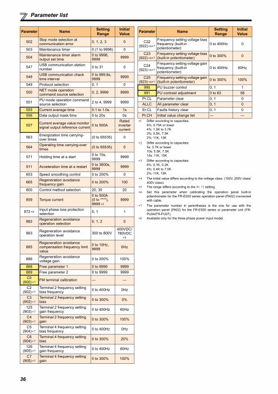
Parameter list
502 Stop mode selection at communication error 0, 1, 2, 3 0
503 Maintenance timer 0 (1 to 9998) 0
504 Maintenance timer alarm output set time
0 to 9998, 9999 9999
547 USB communication station number 0 to 31 0
548 USB communication check time interval
0 to 999.8s, 9999 9999
549 Protocol selection 0, 1 0
550 NET mode operation command source selection 0, 2, 9999 9999
551 PU mode operation command source selection 2 to 4, 9999 9999
555 Current average time 0.1 to 1.0s 1s556 Data output mask time 0 to 20s 0s
557 Current average value monitor signal output reference current 0 to 500A
Rated inverter current
563 Energization time carrying-over times (0 to 65535) 0
564 Operating time carrying-over times (0 to 65535) 0
571 Holding time at a start 0 to 10s, 9999 9999
611 Acceleration time at a restart 0 to 3600s, 9999 9999
653 Speed smoothing control 0 to 200% 0
665 Regeneration avoidance frequency gain 0 to 200% 100
800 Control method selection 20, 30 20
859 Torque current0 to 500A (0 to ****), 9999 ∗5
9999
872 ∗8Input phase loss protection selection 0, 1 1
882 Regeneration avoidance operation selection 0, 1, 2 0
883 Regeneration avoidance operation level 300 to 800V
400VDC/780VDC
∗4
885Regeneration avoidance compensation frequency limit value
0 to 10Hz, 9999 6Hz
886 Regeneration avoidance voltage gain 0 to 200% 100%
888 Free parameter 1 0 to 9999 9999889 Free parameter 2 0 to 9999 9999C0
(900) ∗7FM terminal calibration — —
C2(902) ∗7
Terminal 2 frequency setting bias frequency 0 to 400Hz 0Hz
C3(902) ∗7
Terminal 2 frequency setting bias 0 to 300% 0%
125(903) ∗7
Terminal 2 frequency setting gain frequency 0 to 400Hz 60Hz
C4(903) ∗7
Terminal 2 frequency setting gain 0 to 300% 100%
C5(904) ∗7
Terminal 4 frequency setting bias frequency 0 to 400Hz 0Hz
C6(904) ∗7
Terminal 4 frequency setting bias 0 to 300% 20%
126(905) ∗7
Terminal 4 frequency setting gain frequency 0 to 400Hz 60Hz
C7(905) ∗7
Terminal 4 frequency setting gain 0 to 300% 100%
Parameter Name Setting Range
Initial Value
C22(922) ∗6∗7
Frequency setting voltage bias frequency (built-in potentiometer)
0 to 400Hz 0
C23(922) ∗6∗7
Frequency setting voltage bias (built-in potentiometer) 0 to 300% 0
C24(923) ∗6∗7
Frequency setting voltage gain frequency (built-in potentiometer)
0 to 400Hz 60Hz
C25(923) ∗6∗7
Frequency setting voltage gain (built-in potentiometer) 0 to 300% 100%
990 PU buzzer control 0, 1 1991 PU contrast adjustment 0 to 63 58
Pr.CL Parameter clear 0, 1 0ALLC All parameter clear 0, 1 0Er.CL Faults history clear 0, 1 0Pr.CH Initial value change list — —
∗1 Differ according to capacities.6%: 0.75K or lower4%: 1.5K to 3.7K3%: 5.5K, 7.5K2%: 11K, 15K
∗2 Differ according to capacities. 5s: 3.7K or lower 10s: 5.5K, 7.5K 15s: 11K, 15K
∗3 Differ according to capacities.6%: 0.1K, 0.2K4%: 0.4K to 7.5K2%: 11K, 15K
∗4 The initial value differs according to the voltage class. (100V, 200V class/400V class)
∗5 The range differs according to the Pr. 71 setting.∗6 Set this parameter when calibrating the operation panel built-in
potentiometer for the FR-E500 series operation panel (PA02) connectedwith cable.
∗7 The parameter number in parentheses is the one for use with theoperation panel (PA02) for the FR-E500 series or parameter unit (FR-PU04/FR-PU07).
∗8 Available only for the three-phase power input model.
Parameter Name Setting Range
Initial Value
36
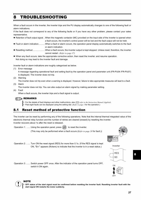
Reset method of protective function
8
8 TROUBLESHOOTING
When a fault occurs in the inverter, the inverter trips and the PU display automatically changes to one of the following fault oralarm indications.If the fault does not correspond to any of the following faults or if you have any other problem, please contact your salesrepresentative.
Retention of fault output signal .. When the magnetic contactor (MC) provided on the input side of the inverter is opened whena fault occurs, the inverter's control power will be lost and the fault output will not be held.
Fault or alarm indication...........When a fault or alarm occurs, the operation panel display automatically switches to the faultor alarm indication.
Resetting method.....................When a fault occurs, the inverter output is kept stopped. Unless reset, therefore, the invertercannot restart. (Refer to page 37)
When any fault occurs, take the appropriate corrective action, then reset the inverter, and resume operation.Not doing so may lead to the inverter fault and damage.
Inverter fault or alarm indications are roughly categorized as below.(1) Error message
A message regarding operational fault and setting fault by the operation panel and parameter unit (FR-PU04 /FR-PU07)is displayed. The inverter does not trip.
(2) WarningThe inverter does not trip even when a warning is displayed. However, failure to take appropriate measures will lead to a fault.
(3) AlarmThe inverter does not trip. You can also output an alarm signal by making parameter setting.
(4) FaultWhen a fault occurs, the inverter trips and a fault signal is output.
8.1 Reset method of protective function
The inverter can be reset by performing any of the following operations. Note that the internal thermal integrated value of theelectronic thermal relay function and the number of retries are cleared (erased) by resetting the inverter.Inverter recovers about 1s after the reset is released.
REMARKSFor the details of fault displays and other malfunctions, also refer to the Instruction Manual (Applied).Past eight faults can be displayed using the setting dial. (Refer to page 3 for the operation.)
Operation 1: ...... Using the operation panel, press to reset the inverter.
(This may only be performed when a fault occurs (Refer to page 38 for fault.))
Operation 2: . ..... Turn ON the reset signal (RES) for more than 0.1s. (If the RES signal is keptON, "Err." appears (flickers) to indicate that the inverter is in a reset status.)
Operation 3: ....... Switch power OFF once. After the indicator of the operation panel turns OFF,switch it ON again.
NOTEOFF status of the start signal must be confirmed before resetting the inverter fault. Resetting inverter fault with thestart signal ON restarts the motor suddenly.
SD
Inverter
RES
ON
OFF
37
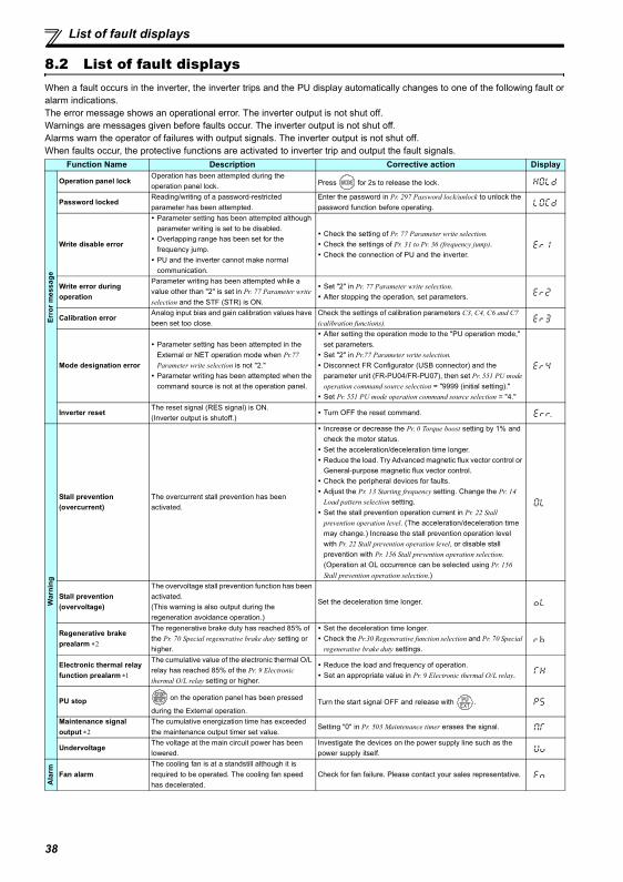
List of fault displays
8.2 List of fault displaysWhen a fault occurs in the inverter, the inverter trips and the PU display automatically changes to one of the following fault oralarm indications.The error message shows an operational error. The inverter output is not shut off.Warnings are messages given before faults occur. The inverter output is not shut off.Alarms warn the operator of failures with output signals. The inverter output is not shut off.When faults occur, the protective functions are activated to inverter trip and output the fault signals.
Function Name Description Corrective action Display
Erro
r mes
sage
Operation panel lockOperation has been attempted during the operation panel lock. Press for 2s to release the lock.
Password lockedReading/writing of a password-restricted parameter has been attempted.
Enter the password in Pr. 297 Password lock/unlock to unlock the password function before operating.
Write disable error
Parameter setting has been attempted although parameter writing is set to be disabled.Overlapping range has been set for the frequency jump.PU and the inverter cannot make normal communication.
Check the setting of Pr. 77 Parameter write selection.Check the settings of Pr. 31 to Pr. 36 (frequency jump).Check the connection of PU and the inverter.
Write error during operation
Parameter writing has been attempted while a value other than "2" is set in Pr. 77 Parameter write selection and the STF (STR) is ON.
Set "2" in Pr. 77 Parameter write selection.After stopping the operation, set parameters.
Calibration errorAnalog input bias and gain calibration values have been set too close.
Check the settings of calibration parameters C3, C4, C6 and C7 (calibration functions).
Mode designation error
Parameter setting has been attempted in the External or NET operation mode when Pr.77 Parameter write selection is not "2."Parameter writing has been attempted when the command source is not at the operation panel.
After setting the operation mode to the "PU operation mode," set parameters. Set "2" in Pr.77 Parameter write selection.Disconnect FR Configurator (USB connector) and the parameter unit (FR-PU04/FR-PU07), then set Pr. 551 PU mode operation command source selection = "9999 (initial setting)."Set Pr. 551 PU mode operation command source selection = "4."
Inverter resetThe reset signal (RES signal) is ON.(Inverter output is shutoff.)
Turn OFF the reset command.
War
ning
Stall prevention (overcurrent)
The overcurrent stall prevention has been activated.
Increase or decrease the Pr. 0 Torque boost setting by 1% and check the motor status.Set the acceleration/deceleration time longer.Reduce the load. Try Advanced magnetic flux vector control or General-purpose magnetic flux vector control.Check the peripheral devices for faults.Adjust the Pr. 13 Starting frequency setting. Change the Pr. 14 Load pattern selection setting.Set the stall prevention operation current in Pr. 22 Stall prevention operation level. (The acceleration/deceleration time may change.) Increase the stall prevention operation level with Pr. 22 Stall prevention operation level, or disable stall prevention with Pr. 156 Stall prevention operation selection. (Operation at OL occurrence can be selected using Pr. 156 Stall prevention operation selection.)
Stall prevention (overvoltage)
The overvoltage stall prevention function has been activated.(This warning is also output during the regeneration avoidance operation.)
Set the deceleration time longer.
Regenerative brake prealarm ∗2
The regenerative brake duty has reached 85% of the Pr. 70 Special regenerative brake duty setting or higher.
Set the deceleration time longer.Check the Pr.30 Regenerative function selection and Pr. 70 Special regenerative brake duty settings.
Electronic thermal relay function prealarm ∗1
The cumulative value of the electronic thermal O/L relay has reached 85% of the Pr. 9 Electronic thermal O/L relay setting or higher.
Reduce the load and frequency of operation.Set an appropriate value in Pr. 9 Electronic thermal O/L relay.
PU stop on the operation panel has been pressed
during the External operation.Turn the start signal OFF and release with .
Maintenance signal output ∗2
The cumulative energization time has exceeded the maintenance output timer set value.
Setting "0" in Pr. 503 Maintenance timer erases the signal.
UndervoltageThe voltage at the main circuit power has been lowered.
Investigate the devices on the power supply line such as the power supply itself.
Ala
rm Fan alarmThe cooling fan is at a standstill although it is required to be operated. The cooling fan speed has decelerated.
Check for fan failure. Please contact your sales representative.
38
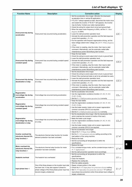
List of fault displays
8
Faul
t
Overcurrent trip during acceleration
Overcurrent has occurred during acceleration.
Set the acceleration time longer. (Shorten the downward acceleration time in vertical lift application.)If "E.OC1" always appears at start, disconnect the motor once and restart the inverter. If "E.OC1" still appears, the inverter may be faulty. Contact your sales representative.Check the wiring for output short circuit and ground fault.When the rated motor frequency is 50Hz, set the Pr. 3 Base frequency to 50Hz.Lower the stall prevention operation level.Activate the stall prevention operation and the fast-response current limit operation. (Pr.156)For the operation with frequent regenerative driving, set the base voltage (rated motor voltage, etc.) in Pr. 19 Base frequency voltage.If the motor is coasting, stop the motor, then input a start command. Alternatively, use the automatic restart after instantaneous power failure/flying start function.
Overcurrent trip during constant speed
Overcurrent has occurred during constant speed operation.
Keep the load stable.Check the wiring to avoid output short circuit or ground fault.Lower the stall prevention operation level.Activate the stall prevention operation and the fast-response current limit operation. (Pr.156)If the motor is coasting, stop the motor, then input a start command. Alternatively, use the automatic restart after instantaneous power failure/flying start function.
Overcurrent trip during deceleration or stop
Overcurrent has occurred during deceleration or at a stop.
Set the deceleration time longer.Check the wiring to avoid output short circuit or ground fault.Check if the mechanical brake is set to be activated too early.Lower the stall prevention operation level.Activate the stall prevention operation and the fast-response current limit operation. (Pr.156) If the motor is coasting, stop the motor, then input a start command. Alternatively, use the automatic restart after instantaneous power failure/flying start function.
Regenerative overvoltage trip during acceleration
Overvoltage has occurred during acceleration.
Set the acceleration time shorter.Use the regeneration avoidance function (Pr. 882, Pr. 883, Pr.885, Pr.886)Set the Pr. 22 Stall prevention operation level correctly.
Regenerative overvoltage trip during constant speed
Overvoltage has occurred during constant speed operation.
Keep the load stable.Use the regeneration avoidance function (Pr. 882, Pr. 883, Pr.885, Pr.886).Use the brake resistor, brake unit or power regeneration common converter (FR-CV) as required.Set the Pr. 22 Stall prevention operation level correctly.
Regenerative overvoltage trip during deceleration or stop
Overvoltage has occurred during deceleration or at a stop.
Set the deceleration time longer. (Set the deceleration time which matches the moment of inertia of the load.)Make the brake cycle longer.Use the regeneration avoidance function (Pr. 882, Pr. 883, Pr.885, Pr.886)Use the brake resistor, brake unit or power regeneration common converter (FR-CV) as required.
Inverter overload trip(electronic thermal O/L relay function) ∗1
The electronic thermal relay function for inverter element protection has been activated.
Set the acceleration time longer.Adjust the Pr. 0 Torque boost setting.Set the Pr. 14 Load pattern selection setting according to the load pattern of the using machine.Reduce the load.Set the surrounding air temperature to within the specifications.
Motor overload trip(electronic thermal O/L relay function) ∗1
The electronic thermal relay function for motor protection has been activated.
Reduce the load.For a constant-torque motor, set the constant-torque motor in Pr. 71 Applied motor.Set the stall prevention operation level accordingly.
Heatsink overheat The heatsink has overheated.
Set the surrounding air temperature to within the specifications.Clean the heatsink.Replace the cooling fan.
Input phase loss ∗2
One of the three phases on the inverter input side has been lost. It may also appear if phase-to-phase voltage of the three-phase power input has become largely unbalanced.
Wire the cables properly.Repair a break portion in the cable.Check the Pr. 872 Input phase loss protection selection setting.Set Pr. 872 Input phase loss protection selection = "0" (without input phase loss protection) when three-phase input voltage is largely unbalanced.
Function Name Description Corrective action Display
39
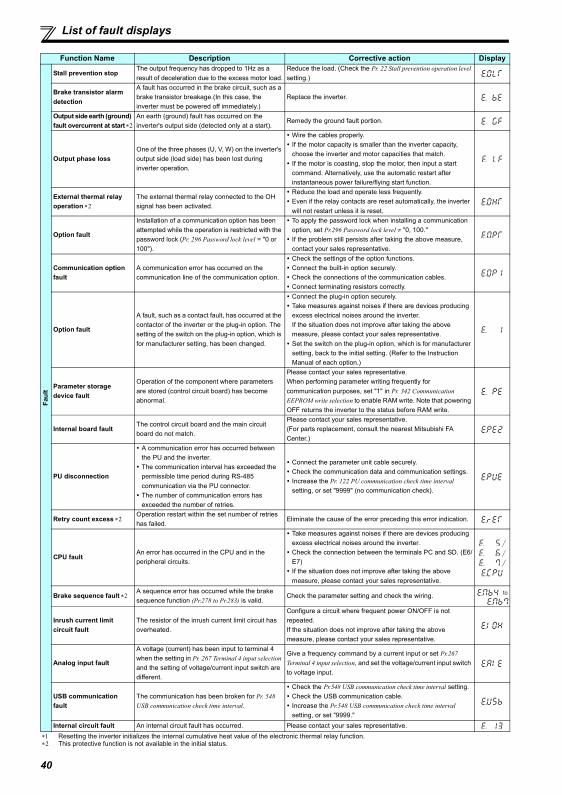
List of fault displays
Fault
Stall prevention stopThe output frequency has dropped to 1Hz as a result of deceleration due to the excess motor load.
Reduce the load. (Check the Pr. 22 Stall prevention operation level setting.)
Brake transistor alarm detection
A fault has occurred in the brake circuit, such as a brake transistor breakage.(In this case, the inverter must be powered off immediately.)
Replace the inverter.
Output side earth (ground) fault overcurrent at start ∗2
An earth (ground) fault has occurred on the inverter's output side (detected only at a start).
Remedy the ground fault portion.
Output phase lossOne of the three phases (U, V, W) on the inverter's output side (load side) has been lost during inverter operation.
Wire the cables properly.If the motor capacity is smaller than the inverter capacity, choose the inverter and motor capacities that match.If the motor is coasting, stop the motor, then input a start command. Alternatively, use the automatic restart after instantaneous power failure/flying start function.
External thermal relay operation ∗2
The external thermal relay connected to the OH signal has been activated.
Reduce the load and operate less frequently.Even if the relay contacts are reset automatically, the inverter will not restart unless it is reset.
Option fault
Installation of a communication option has been attempted while the operation is restricted with the password lock (Pr. 296 Password lock level = "0 or 100").
To apply the password lock when installing a communication option, set Pr.296 Password lock level ≠ "0, 100."If the problem still persists after taking the above measure, contact your sales representative.
Communication option fault
A communication error has occurred on the communication line of the communication option.
Check the settings of the option functions. Connect the built-in option securely.Check the connections of the communication cables.Connect terminating resistors correctly.
Option fault
A fault, such as a contact fault, has occurred at the contactor of the inverter or the plug-in option. The setting of the switch on the plug-in option, which is for manufacturer setting, has been changed.
Connect the plug-in option securely.Take measures against noises if there are devices producing excess electrical noises around the inverter.If the situation does not improve after taking the above measure, please contact your sales representative.Set the switch on the plug-in option, which is for manufacturer setting, back to the initial setting. (Refer to the Instruction Manual of each option.)
Parameter storage device fault
Operation of the component where parameters are stored (control circuit board) has become abnormal.
Please contact your sales representative.When performing parameter writing frequently for communication purposes, set "1" in Pr. 342 Communication EEPROM write selection to enable RAM write. Note that powering OFF returns the inverter to the status before RAM write.
Internal board faultThe control circuit board and the main circuit board do not match.
Please contact your sales representative.(For parts replacement, consult the nearest Mitsubishi FA Center.)
PU disconnection
A communication error has occurred between the PU and the inverter.The communication interval has exceeded the permissible time period during RS-485 communication via the PU connector.The number of communication errors has exceeded the number of retries.
Connect the parameter unit cable securely.Check the communication data and communication settings.Increase the Pr. 122 PU communication check time interval setting, or set "9999" (no communication check).
Retry count excess ∗2Operation restart within the set number of retries has failed.
Eliminate the cause of the error preceding this error indication.
CPU faultAn error has occurred in the CPU and in the peripheral circuits.
Take measures against noises if there are devices producing excess electrical noises around the inverter.Check the connection between the terminals PC and SD. (E6/E7)If the situation does not improve after taking the above measure, please contact your sales representative.
///
Brake sequence fault ∗2A sequence error has occurred while the brake sequence function (Pr.278 to Pr.283) is valid.
Check the parameter setting and check the wiring.
Inrush current limit circuit fault
The resistor of the inrush current limit circuit has overheated.
Configure a circuit where frequent power ON/OFF is not repeated.If the situation does not improve after taking the above measure, please contact your sales representative.
Analog input fault
A voltage (current) has been input to terminal 4 when the setting in Pr. 267 Terminal 4 input selection and the setting of voltage/current input switch are different.
Give a frequency command by a current input or set Pr.267 Terminal 4 input selection, and set the voltage/current input switch to voltage input.
USB communication fault
The communication has been broken for Pr. 548 USB communication check time interval.
Check the Pr.548 USB communication check time interval setting.Check the USB communication cable.Increase the Pr.548 USB communication check time interval setting, or set "9999."
Internal circuit fault An internal circuit fault has occurred. Please contact your sales representative.∗1 Resetting the inverter initializes the internal cumulative heat value of the electronic thermal relay function.∗2 This protective function is not available in the initial status.
Function Name Description Corrective action Display
to
40
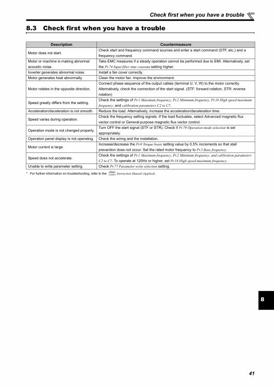
Check first when you have a trouble
8
8.3 Check first when you have a trouble
* For further information on troubleshooting, refer to the Instruction Manual (Applied).
Description Countermeasure
Motor does not start.Check start and frequency command sources and enter a start command (STF, etc.) and a frequency command.
Motor or machine is making abnormal acoustic noise.
Take EMC measures if a steady operation cannot be performed due to EMI. Alternatively, set the Pr.74 Input filter time constant setting higher.
Inverter generates abnormal noise. Install a fan cover correctly.Motor generates heat abnormally. Clean the motor fan. Improve the environment.
Motor rotates in the opposite direction.Connect phase sequence of the output cables (terminal U, V, W) to the motor correctly.Alternatively, check the connection of the start signal. (STF: forward rotation, STR: reverse rotation)
Speed greatly differs from the setting.Check the settings of Pr.1 Maximum frequency, Pr.2 Minimum frequency, Pr.18 High speed maximum frequency, and calibration parameters C2 to C7.
Acceleration/deceleration is not smooth. Reduce the load. Alternatively, increase the acceleration/deceleration time.
Speed varies during operation.Check the frequency setting signals. If the load fluctuates, select Advanced magnetic flux vector control or General-purpose magnetic flux vector control.
Operation mode is not changed properly.Turn OFF the start signal (STF or STR). Check if Pr.79 Operation mode selection is set appropriately.
Operation panel display is not operating. Check the wiring and the installation.
Motor current is large.Increase/decrease the Pr.0 Torque boost setting value by 0.5% increments so that stall prevention does not occur. Set the rated motor frequency to Pr.3 Base frequency.
Speed does not accelerate.Check the settings of Pr.1 Maximum frequency, Pr.2 Minimum frequency, and calibration parameters C2 to C7. To operate at 120Hz or higher, set Pr.18 High speed maximum frequency.
Unable to write parameter setting. Check Pr.77 Parameter write selection setting.
41
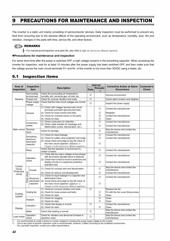
Inspection items
9 PRECAUTIONS FOR MAINTENANCE AND INSPECTION
The inverter is a static unit mainly consisting of semiconductor devices. Daily inspection must be performed to prevent anyfault from occurring due to the adverse effects of the operating environment, such as temperature, humidity, dust, dirt andvibration, changes in the parts with time, service life, and other factors.
Precautions for maintenance and inspectionFor some short time after the power is switched OFF, a high voltage remains in the smoothing capacitor. When accessing theinverter for inspection, wait for at least 10 minutes after the power supply has been switched OFF, and then make sure thatthe voltage across the main circuit terminals P/+ and N/- of the inverter is not more than 30VDC using a tester, etc.
9.1 Inspection items
∗1 It is recommended to install a device to monitor voltage for checking the power supply voltage to the inverter.∗2 One to two years of periodic inspection cycle is recommended. However, it differs according to the installation environment.
For a periodic inspection, contact your sales representative.
REMARKSFor maintenance/inspection and parts life, also refer to the Instruction Manual (Applied).
Area of Inspection
Inspection Item Description
Interval Corrective Action at Alarm Occurrence
Customer's CheckDaily Periodic
∗2
General
Surrounding environment
Check the surrounding air temperature, humidity, dirt, corrosive gas, oil mist, etc. Improve environment
Overall unit Check for unusual vibration and noise. Check alarm location and retightenPower supply voltage
Check that the main circuit voltages are normal. ∗1
Inspect the power supply
Main circuit
General
(1) Check with megger (across main circuit terminals and earth (ground) terminal). Contact the manufacturer
(2) Check for loose screws and bolts. Retighten(3) Check for overheat traces on the parts. Contact the manufacturer(4) Check for stain. Clean
Conductors, cables
(1) Check conductors for distortion.(2) Check cable sheaths for breakage and
deterioration (crack, discoloration, etc.).
Contact the manufacturer
Contact the manufacturer
Terminal block Check for damage. Stop the device and contact the
manufacturer.
Smoothing aluminum electrolytic capacitor
(1) Check for liquid leakage. Contact the manufacturer(2) Check for safety valve projection and bulge. Contact the manufacturer(3) Visual check and judge by the life check of
the main circuit capacitor ( Refer to Chapter 4 of the Instruction Manual (Applied).)
Relay Check that the operation is normal and no chatter is heard. Contact the manufacturer
Control circuit,
Protective circuit
Operation check
(1) Check that the output voltages across phases with the inverter operated alone is balanced. Contact the manufacturer
(2) Check that no fault is found in protective and display circuits in a sequence protective operation test.
Contact the manufacturer
Par
ts c
heck
Overall(1) Check for unusual odor and discoloration. Stop the device and contact the
manufacturer.(2) Check for serious rust development. Contact the manufacturer
Aluminum electrolytic capacitor
(1) Check for liquid leakage in a capacitor and deformation trace. Contact the manufacturer
(2) Visual check and judge by the life check of the main circuit capacitor ( Refer to Chapter 4 of the Instruction Manual (Applied).)
Cooling system
Cooling fan(1) Check for unusual vibration and noise. Replace the fan(2) Check for loose screws and bolts. Fix with the fan cover fixing screws(3) Check for stain. Clean
Heatsink(1) Check for clogging. Clean(2) Check for stain. Clean
DisplayIndication
(1) Check that display is normal. Contact the manufacturer(2) Check for stain. Clean
Meter Check that reading is normal. Stop the device and contact the manufacturer.
Load motor Operation check
Check for vibration and abnormal increase in operation noise.
Stop the device and contact the manufacturer.
42
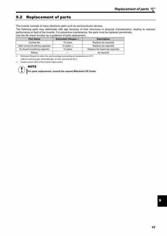
Replacement of parts
9
9.2 Replacement of parts
The inverter consists of many electronic parts such as semiconductor devices.The following parts may deteriorate with age because of their structures or physical characteristics, leading to reducedperformance or fault of the inverter. For preventive maintenance, the parts must be replaced periodically.Use the life check function as a guidance of parts replacement.
∗1 Estimated lifespan for when the yearly average surrounding air temperature is 40°C(without corrosive gas, flammable gas, oil mist, dust and dirt etc.)
∗2 Output current: 80% of the inverter rated current
Part Name Estimated lifespan ∗1 DescriptionCooling fan 10 years Replace (as required)
Main circuit smoothing capacitor 10 years ∗2 Replace (as required)On-board smoothing capacitor 10 years Replace the board (as required)
Relays — as required
NOTEFor parts replacement, consult the nearest Mitsubishi FA Center.
43
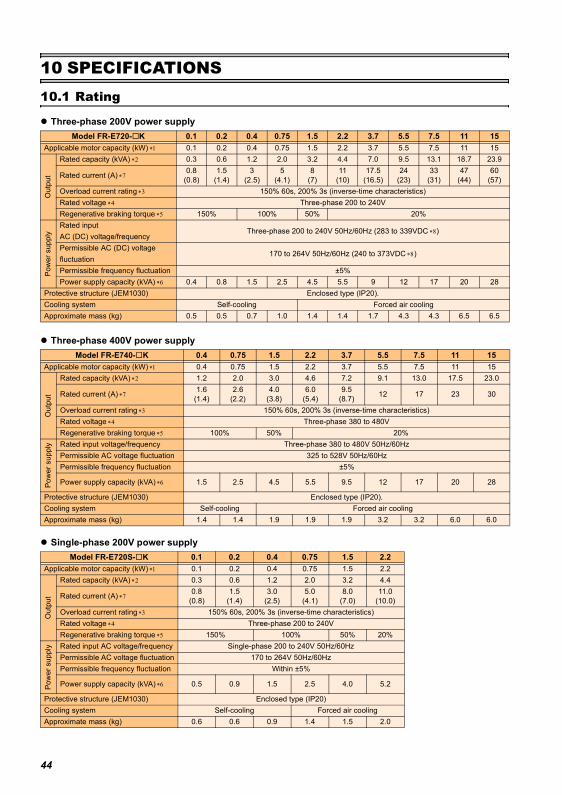
Rating
10 SPECIFICATIONS10.1 Rating
Three-phase 200V power supply
Three-phase 400V power supply
Single-phase 200V power supply
Model FR-E720- K 0.1 0.2 0.4 0.75 1.5 2.2 3.7 5.5 7.5 11 15Applicable motor capacity (kW) ∗1 0.1 0.2 0.4 0.75 1.5 2.2 3.7 5.5 7.5 11 15
Out
put
Rated capacity (kVA) ∗2 0.3 0.6 1.2 2.0 3.2 4.4 7.0 9.5 13.1 18.7 23.9
Rated current (A) ∗70.8
(0.8)1.5
(1.4)3
(2.5)5
(4.1)8
(7)11
(10)17.5
(16.5)24
(23)33
(31)47
(44)60
(57)Overload current rating ∗3 150% 60s, 200% 3s (inverse-time characteristics)Rated voltage ∗4 Three-phase 200 to 240VRegenerative braking torque ∗5 150% 100% 50% 20%
Pow
er s
uppl
y
Rated inputAC (DC) voltage/frequency
Three-phase 200 to 240V 50Hz/60Hz (283 to 339VDC ∗8)
Permissible AC (DC) voltage fluctuation
170 to 264V 50Hz/60Hz (240 to 373VDC ∗8)
Permissible frequency fluctuation ±5%Power supply capacity (kVA) ∗6 0.4 0.8 1.5 2.5 4.5 5.5 9 12 17 20 28
Protective structure (JEM1030) Enclosed type (IP20).Cooling system Self-cooling Forced air coolingApproximate mass (kg) 0.5 0.5 0.7 1.0 1.4 1.4 1.7 4.3 4.3 6.5 6.5
Model FR-E740- K 0.4 0.75 1.5 2.2 3.7 5.5 7.5 11 15Applicable motor capacity (kW) ∗1 0.4 0.75 1.5 2.2 3.7 5.5 7.5 11 15
Out
put
Rated capacity (kVA) ∗2 1.2 2.0 3.0 4.6 7.2 9.1 13.0 17.5 23.0
Rated current (A) ∗71.6
(1.4)2.6
(2.2)4.0
(3.8)6.0
(5.4)9.5
(8.7) 12 17 23 30
Overload current rating ∗3 150% 60s, 200% 3s (inverse-time characteristics)Rated voltage ∗4 Three-phase 380 to 480VRegenerative braking torque ∗5 100% 50% 20%
Pow
er s
uppl
y Rated input voltage/frequency Three-phase 380 to 480V 50Hz/60HzPermissible AC voltage fluctuation 325 to 528V 50Hz/60HzPermissible frequency fluctuation ±5%
Power supply capacity (kVA) ∗6 1.5 2.5 4.5 5.5 9.5 12 17 20 28
Protective structure (JEM1030) Enclosed type (IP20).Cooling system Self-cooling Forced air coolingApproximate mass (kg) 1.4 1.4 1.9 1.9 1.9 3.2 3.2 6.0 6.0
Model FR-E720S- K 0.1 0.2 0.4 0.75 1.5 2.2Applicable motor capacity (kW) ∗1 0.1 0.2 0.4 0.75 1.5 2.2
Out
put
Rated capacity (kVA) ∗2 0.3 0.6 1.2 2.0 3.2 4.4
Rated current (A) ∗70.8
(0.8)1.5
(1.4)3.0
(2.5)5.0
(4.1)8.0
(7.0)11.0
(10.0)Overload current rating ∗3 150% 60s, 200% 3s (inverse-time characteristics)Rated voltage ∗4 Three-phase 200 to 240VRegenerative braking torque ∗5 150% 100% 50% 20%
Pow
er s
uppl
y Rated input AC voltage/frequency Single-phase 200 to 240V 50Hz/60HzPermissible AC voltage fluctuation 170 to 264V 50Hz/60HzPermissible frequency fluctuation Within ±5%
Power supply capacity (kVA) ∗6 0.5 0.9 1.5 2.5 4.0 5.2
Protective structure (JEM1030) Enclosed type (IP20)Cooling system Self-cooling Forced air coolingApproximate mass (kg) 0.6 0.6 0.9 1.4 1.5 2.0
44
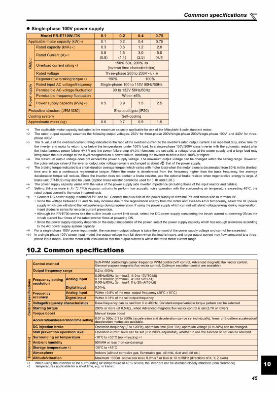
Common specifications
10
Single-phase 100V power supply
∗1 The applicable motor capacity indicated is the maximum capacity applicable for use of the Mitsubishi 4-pole standard motor.∗2 The rated output capacity assumes the following output voltages: 230V for three-phase 200V/single-phase 200V/single-phase 100V, and 440V for three-
phase 400V.∗3 The % value of the overload current rating indicated is the ratio of the overload current to the inverter's rated output current. For repeated duty, allow time for
the inverter and motor to return to or below the temperatures under 100% load. In a single-phase 100V/200V class inverter with the automatic restart afterthe instantaneous power failure (Pr.57) and the power failure stop (Pr.261) functions are set valid, a voltage drop at the power supply and a large load maybring down the bus voltage to the level recognized as a power failure, disabling the inverter to drive a load 100% or higher.
∗4 The maximum output voltage does not exceed the power supply voltage. The maximum output voltage can be changed within the setting range. However,the pulse voltage value of the inverter output side voltage remains unchanged at about that of the power supply.
∗5 The braking torque indicated is a short-duration average torque (which varies with motor loss) when the motor alone is decelerated from 60Hz in the shortesttime and is not a continuous regenerative torque. When the motor is decelerated from the frequency higher than the base frequency, the averagedeceleration torque will reduce. Since the inverter does not contain a brake resistor, use the optional brake resistor when regenerative energy is large. Abrake unit (FR-BU2) may also be used. (Option brake resistor cannot be used for 0.1K and 0.2K.)
∗6 The power supply capacity varies with the value of the power supply side inverter impedance (including those of the input reactor and cables).∗7 Setting 2kHz or more in Pr. 72 PWM frequency selection to perform low acoustic noise operation with the surrounding air temperature exceeding 40°C, the
rated output current is the value in parenthesis.∗8 Connect DC power supply to terminal P/+ and N/-. Connect the plus side of the power supply to terminal P/+ and minus side to terminal N/-.
Since the voltage between P/+ and N/- may increase due to the regeneration energy from the motor and exceeds 415V temporarily, select the DC powersupply which can withstand the voltage/energy during regeneration. If using the power supply which can not withstand voltage/energy during regeneration,insert diodes in series for reverse current prevention.Although the FR-E700 series has the built-in inrush current limit circuit, select the DC power supply considering the inrush current at powering ON as theinrush current four times of the rated inverter flows at powering ON.Since the power supply capacity depends on the output impedance of the power, select the power supply capacity which has enough allowance accordingto the AC power supply system capacity.
∗9 For a single-phase 100V power input model, the maximum output voltage is twice the amount of the power supply voltage and cannot be exceeded.∗10 In a single-phase 100V power input model, the output voltage may fall down when the load is heavy, and larger output current may flow compared to a three-
phase input model. Use the motor with less load so that the output current is within the rated motor current range.
10.2 Common specifications
Model FR-E710W- K 0.1 0.2 0.4 0.75Applicable motor capacity (kW) ∗1 0.1 0.2 0.4 0.75
Out
put
Rated capacity (kVA) ∗2 0.3 0.6 1.2 2.0
Rated Current (A) ∗70.8
(0.8)1.5
(1.4)3.0
(2.5)5.0
(4.1)
Overload current rating ∗3150% 60s, 200% 3s
(inverse-time characteristics)Rated voltage Three-phase 200 to 230V ∗9, ∗10
Regenerative braking torque ∗5 150% 100%
Pow
er s
uppl
y Rated input AC voltage/frequency Single-phase 100 to 115V 50Hz/60HzPermissible AC voltage fluctuation 90 to 132V 50Hz/60HzPermissible frequency fluctuation Within ±5%
Power supply capacity (kVA) ∗6 0.5 0.9 1.5 2.5
Protective structure (JEM1030) Enclosed type (IP20)Cooling system Self-coolingApproximate mass (kg) 0.6 0.7 0.9 1.5
Con
trol
spe
cific
atio
ns
Control method Soft-PWM control/high carrier frequency PWM control (V/F control, Advanced magnetic flux vector control, General-purpose magnetic flux vector control, Optimum excitation control are available)
Output frequency range 0.2 to 400Hz
Frequency setting resolution
Analog input0.06Hz/60Hz (terminal2, 4: 0 to 10V/10-bit)0.12Hz/60Hz (terminal2, 4: 0 to 5V/9-bit)0.06Hz/60Hz (terminal4: 0 to 20mA/10-bit)
Digital input 0.01Hz
Frequency accuracy
Analog input Within ±0.5% of the max. output frequency (25°C ±10°C)Digital input Within 0.01% of the set output frequency
Voltage/frequency characteristics Base frequency can be set from 0 to 400Hz, Constant-torque/variable torque pattern can be selectedStarting torque 200% or more (at 0.5Hz)...when Advanced magnetic flux vector control is set (3.7K or lower)Torque boost Manual torque boost
Acceleration/deceleration time setting 0.01 to 360s, 0.1 to 3600s (acceleration and deceleration can be set individually), linear or S-pattern acceleration/deceleration modes are available.
DC injection brake Operation frequency (0 to 120Hz), operation time (0 to 10s), operation voltage (0 to 30%) can be changed.Stall prevention operation level Operation current level can be set (0 to 200% adjustable), whether to use the function or not can be selected
Envi
ronm
ent Surrounding air temperature -10°C to +50°C (non-freezing) ∗1
Ambient humidity 90%RH or less (non-condensing)Storage temperature ∗2 -20°C to +65°CAtmosphere Indoors (without corrosive gas, flammable gas, oil mist, dust and dirt etc.)Altitude/vibration Maximum 1000m above sea level, 5.9m/s 2 or less at 10 to 55Hz (directions of X, Y, Z axes)
∗1 When using the inverters at the surrounding air temperature of 40°C or less, the inverters can be installed closely attached (0cm clearance).∗2 Temperatures applicable for a short time, e.g. in transit.
2
45
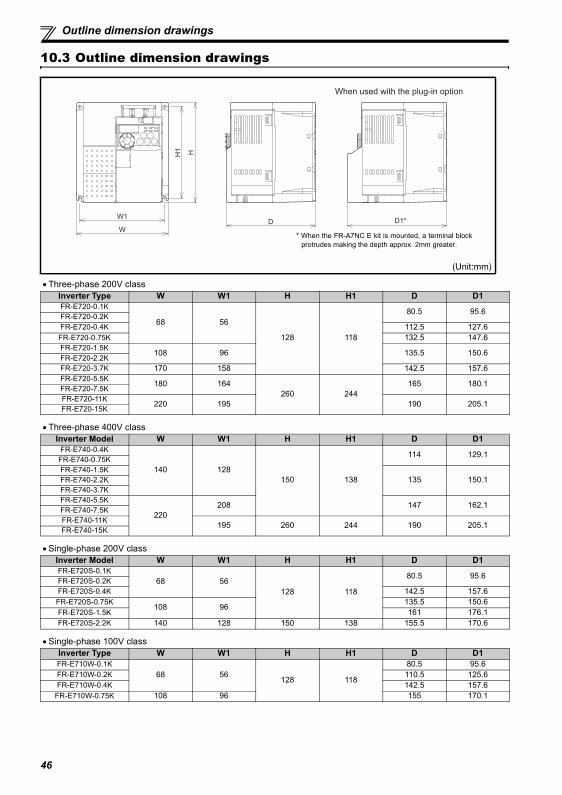
46
Outline dimension drawings
10.3 Outline dimension drawings
• Three-phase 200V class
• Three-phase 400V class
• Single-phase 200V class
• Single-phase 100V class
(Unit:mm)
Inverter Type W W1 H H1 D D1FR-E720-0.1K
68 56
128 118
80.5 95.6FR-E720-0.2KFR-E720-0.4K 112.5 127.6FR-E720-0.75K 132.5 147.6FR-E720-1.5K 108 96 135.5 150.6FR-E720-2.2KFR-E720-3.7K 170 158 142.5 157.6FR-E720-5.5K 180 164
260 244165 180.1FR-E720-7.5K
FR-E720-11K 220 195 190 205.1FR-E720-15K
Inverter Model W W1 H H1 D D1FR-E740-0.4K
140 128150 138
114 129.1FR-E740-0.75KFR-E740-1.5K
135 150.1FR-E740-2.2KFR-E740-3.7KFR-E740-5.5K
220208 147 162.1FR-E740-7.5K
FR-E740-11K 195 260 244 190 205.1FR-E740-15K
Inverter Model W W1 H H1 D D1FR-E720S-0.1K
68 56128 118
80.5 95.6FR-E720S-0.2KFR-E720S-0.4K 142.5 157.6FR-E720S-0.75K 108 96 135.5 150.6FR-E720S-1.5K 161 176.1FR-E720S-2.2K 140 128 150 138 155.5 170.6
Inverter Type W W1 H H1 D D1FR-E710W-0.1K
68 56 128 118
80.5 95.6FR-E710W-0.2K 110.5 125.6FR-E710W-0.4K 142.5 157.6
FR-E710W-0.75K 108 96 155 170.1
DW1
W
H1 H
D1*
When used with the plug-in option
* When the FR-A7NC E kit is mounted, a terminal blockprotrudes making the depth approx. 2mm greater.
APPENDIX
The EU Directives are issued to standardize different national regulations of the EU Member States and to facilitate freemovement of the equipment, whose safety is ensured, in the EU territory.Since 1996, compliance with the EMC Directive that is one of the EU Directives has been legally required. Since 1997,compliance with the Low Voltage Directive, another EU Directive, has been also legally required. When a manufacturerconfirms its equipment to be compliant with the EMC Directive and the Low Voltage Directive, the manufacturer must declarethe conformity and affix the CE marking.
The authorized representative in the EU
The authorized representative in the EU is shown below.Name: Mitsubishi Electric Europe B.V.Address: Gothaer Strasse 8, 40880 Ratingen, Germany
NoteWe declare that this inverter, when equipped with the dedicated EMC filter, conforms with the EMC Directive in industrialenvironments and affix the CE marking on the inverter. When using the inverter in a residential area, take appropriatemeasures and ensure the conformity of the inverter used in the residential area.
(1) EMC DirectiveWe declare that this inverter, when equipped with the EMC Directive compliant EMC filter, conforms with the EMC Directiveand affix the CE marking on the inverter (except the single-phase 100V power supply model).
• EMC Directive: 2004/108/EC• Standard(s): EN61800-3:2004 (Second environment / PDS Category "C3")
Note: First environmentEnvironment including residential buildings. Includes building directly connected without a transformer to the lowvoltage power supply network which supplies power to residential buildings.
Second environmentEnvironment including all buildings except buildings directly connected without a transformer to the lower voltagepower supply network which supplies power to residential buildings.
Note∗ Set the EMC Directive compliant EMC filter to the inverter. Insert line noise filters and ferrite cores to the power and
control cables as required.∗ Connect the inverter to an earthed power supply.∗ Install a motor, the EMC Directive compliant EMC filter, and a control cable according to the instructions written in the
EMC Installation Guidelines (BCN-A21041-204). (Please contact your sales representative for the EMC InstallationGuidelines.)
∗ The cable length between the inverter and the motor is 5m maximum.∗ Confirm that the final integrated system with the inverter conforms with the EMC Directive.
Appendix 1 Instructions for compliance with the EU Directives
47
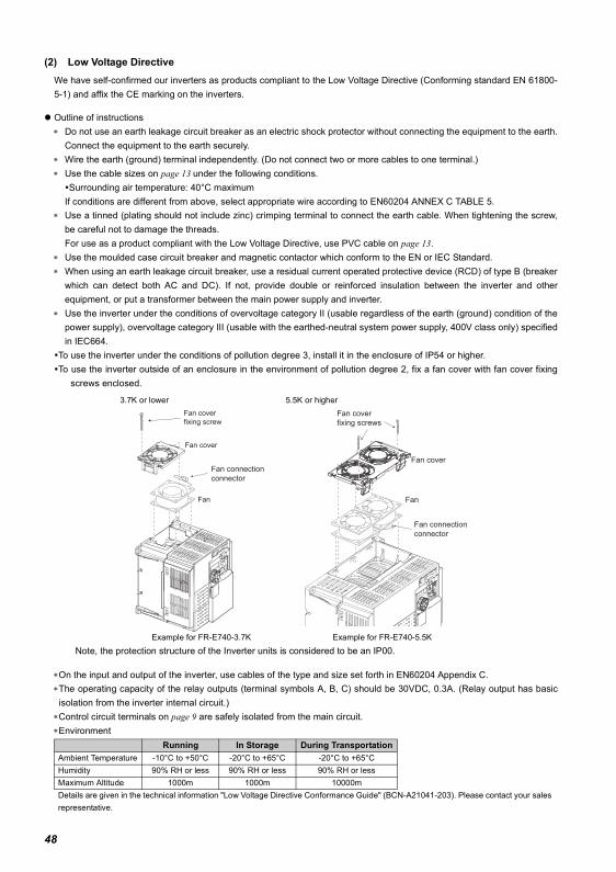
(2) Low Voltage DirectiveWe have self-confirmed our inverters as products compliant to the Low Voltage Directive (Conforming standard EN 61800-5-1) and affix the CE marking on the inverters.
Outline of instructions∗ Do not use an earth leakage circuit breaker as an electric shock protector without connecting the equipment to the earth.
Connect the equipment to the earth securely.∗ Wire the earth (ground) terminal independently. (Do not connect two or more cables to one terminal.)∗ Use the cable sizes on page 13 under the following conditions.
Surrounding air temperature: 40°C maximumIf conditions are different from above, select appropriate wire according to EN60204 ANNEX C TABLE 5.
∗ Use a tinned (plating should not include zinc) crimping terminal to connect the earth cable. When tightening the screw,be careful not to damage the threads.For use as a product compliant with the Low Voltage Directive, use PVC cable on page 13.
∗ Use the moulded case circuit breaker and magnetic contactor which conform to the EN or IEC Standard.∗ When using an earth leakage circuit breaker, use a residual current operated protective device (RCD) of type B (breaker
which can detect both AC and DC). If not, provide double or reinforced insulation between the inverter and otherequipment, or put a transformer between the main power supply and inverter.
∗ Use the inverter under the conditions of overvoltage category II (usable regardless of the earth (ground) condition of thepower supply), overvoltage category III (usable with the earthed-neutral system power supply, 400V class only) specifiedin IEC664.
To use the inverter under the conditions of pollution degree 3, install it in the enclosure of IP54 or higher.To use the inverter outside of an enclosure in the environment of pollution degree 2, fix a fan cover with fan cover fixing
screws enclosed.
Note, the protection structure of the Inverter units is considered to be an IP00.
∗On the input and output of the inverter, use cables of the type and size set forth in EN60204 Appendix C.∗The operating capacity of the relay outputs (terminal symbols A, B, C) should be 30VDC, 0.3A. (Relay output has basicisolation from the inverter internal circuit.)
∗Control circuit terminals on page 9 are safely isolated from the main circuit.∗Environment
3.7K or lower 5.5K or higher
Example for FR-E740-3.7K Example for FR-E740-5.5K
Running In Storage During TransportationAmbient Temperature -10°C to +50°C -20°C to +65°C -20°C to +65°CHumidity 90% RH or less 90% RH or less 90% RH or lessMaximum Altitude 1000m 1000m 10000mDetails are given in the technical information "Low Voltage Directive Conformance Guide" (BCN-A21041-203). Please contact your sales representative.
Fan connection
connector
Fan
Fan cover
Fan cover
fixing screw
Fan
Fan cover
Fan cover
fixing screws
Fan connection
connector
48
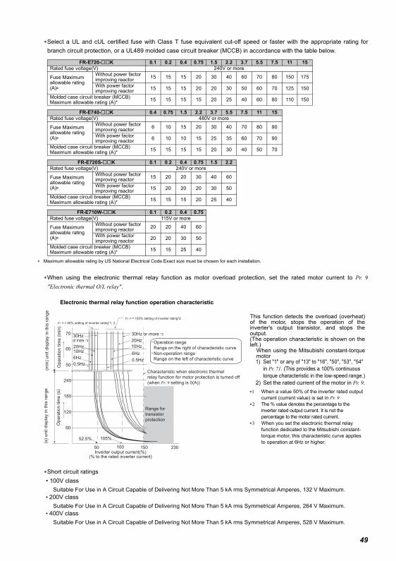
∗Select a UL and cUL certified fuse with Class T fuse equivalent cut-off speed or faster with the appropriate rating forbranch circuit protection, or a UL489 molded case circuit breaker (MCCB) in accordance with the table below.
∗ Maximum allowable rating by US National Electrical Code.Exact size must be chosen for each installation.
∗When using the electronic thermal relay function as motor overload protection, set the rated motor current to Pr. 9"Electronic thermal O/L relay".
∗Short circuit ratings • 100V class
Suitable For Use in A Circuit Capable of Delivering Not More Than 5 kA rms Symmetrical Amperes, 132 V Maximum. • 200V class
Suitable For Use in A Circuit Capable of Delivering Not More Than 5 kA rms Symmetrical Amperes, 264 V Maximum. • 400V class
Suitable For Use in A Circuit Capable of Delivering Not More Than 5 kA rms Symmetrical Amperes, 528 V Maximum.
FR-E720- K 0.1 0.2 0.4 0.75 1.5 2.2 3.7 5.5 7.5 11 15Rated fuse voltage(V) 240V or more
Fuse Maximum allowable rating (A)∗
Without power factor improving reactor 15 15 15 20 30 40 60 70 80 150 175
With power factor improving reactor 15 15 15 20 20 30 50 60 70 125 150
Molded case circuit breaker (MCCB)Maximum allowable rating (A)* 15 15 15 15 20 25 40 60 80 110 150
FR-E740- K 0.4 0.75 1.5 2.2 3.7 5.5 7.5 11 15Rated fuse voltage(V) 480V or more
Fuse Maximum allowable rating (A)∗
Without power factor improving reactor 6 10 15 20 30 40 70 80 90
With power factor improving reactor 6 10 10 15 25 35 60 70 90
Molded case circuit breaker (MCCB)Maximum allowable rating (A)* 15 15 15 15 20 30 40 50 70
FR-E720S- K 0.1 0.2 0.4 0.75 1.5 2.2Rated fuse voltage(V) 240V or more
Fuse Maximum allowable rating (A)∗
Without power factor improving reactor 15 20 20 30 40 60
With power factor improving reactor 15 20 20 20 30 50
Molded case circuit breaker (MCCB)Maximum allowable rating (A)* 15 15 15 20 25 40
FR-E710W- K 0.1 0.2 0.4 0.75Rated fuse voltage(V) 115V or more
Fuse Maximum allowable rating (A)∗
Without power factor improving reactor 20 20 40 60
With power factor improving reactor 20 20 30 50
Molded case circuit breaker (MCCB)Maximum allowable rating (A)* 15 15 25 40
This function detects the overload (overheat)of the motor, stops the operation of theinverter's output transistor, and stops theoutput. (The operation characteristic is shown on theleft.)
When using the Mitsubishi constant-torquemotor1) Set "1" or any of "13" to "16", "50", "53", "54"
in Pr. 71. (This provides a 100% continuous torque characteristic in the low-speed range.)
2) Set the rated current of the motor in Pr. 9.∗1 When a value 50% of the inverter rated output
current (current value) is set in Pr. 9 ∗2 The % value denotes the percentage to the
inverter rated output current. It is not the percentage to the motor rated current.
∗3 When you set the electronic thermal relay function dedicated to the Mitsubishi constant-torque motor, this characteristic curve applies to operation at 6Hz or higher.
Operation range
Range on the right of characteristic curve
Non-operation range
Range on the left of characteristic curve
Range for
transistor
protection
Inverter output current(%)(% to the rated inverter current)
52.5% 105%
50 100 150
60
120
180
240
50
60
70
(min
) unit d
ispla
y in this
range
Opera
tion tim
e (
min
)
Pr. 9 = 50% setting of inverter rating*1, 2
Pr. 9 = 100% setting of inverter rating*2
(s)
unit d
ispla
y in this
range
Opera
tion tim
e (
s)
Characteristic when electronic thermal
relay function for motor protection is turned off
(when Pr. 9 setting is 0(A))
6Hz
20Hz
10Hz
6Hz
0.5Hz
30Hz or more *330Hz or more *3
20Hz10Hz
0.5Hz
230
Electronic thermal relay function operation characteristic
49
50
(Standard to comply with: UL 508C, CSA C22.2 No. 14)
1. General PrecautionThe bus capacitor discharge time is 10 minutes. Before starting wiring or inspection, switch power off, wait for more than 10 minutes,and check for residual voltage between terminal P/+ and N/- with a meter etc., to avoid a hazard of electrical shock.
2. InstallationInverter have been approved as products for use in enclosure and approval tests were conducted under the following conditions.Design the enclosure so that the surrounding air temperature, humidity and ambience of the inverter will satisfy the abovespecifications.Wiring protectionFor installation in the United States, branch circuit protection must be provided in accordance with the National Electrical Code andany applicable provincial codes.For installation in Canada, branch circuit protection must be provided in accordance with the Canadian Electrical Code and anyapplicable provincial codes. As specified on page 49, UL Class T fuses or any faster acting fuse with the appropriate rating or ListedUL 489 Molded Case Circuit Breaker (MCCB) must be employed.
3. Short circuit ratings • 100V class
Suitable For Use in A Circuit Capable of Delivering Not More Than 100 kA rms Symmetrical Amperes, 132 V Maximum. • 200V class
Suitable For Use in A Circuit Capable of Delivering Not More Than 100 kA rms Symmetrical Amperes, 264 V Maximum. • 400V class
Suitable For Use in A Circuit Capable of Delivering Not More Than 100 kA rms Symmetrical Amperes, 528 V Maximum.
4. WiringFor wiring the input (R/L1, S/L2, T/L3) and output (U, V, W) terminals of the inverter, use the UL Listed copper, stranded wires(rated at 75°C) and round crimping terminals. Crimp the crimping terminals with the crimping tool recommended by the terminalmaker.
5. Motor overload protectionWhen using the electronic thermal relay function as motor overload protection, set the rated motor current to Pr. 9 "Electronic thermalO/L relay". (Refer to page 49)
Appendix 2 Instructions for UL and cUL

51
MEMO

52
MEMO
53
REVISIONS*The manual number is given on the bottom left of the back cover.
For Maximum Safety• Mitsubishi inverters are not designed or manufactured to be used in equipment or systems in situations that
can affect or endanger human life.• When considering this product for operation in special applications such as machinery or systems used in
passenger transportation, medical, aerospace, atomic power, electric power, or submarine repeatingapplications, please contact your nearest Mitsubishi sales representative.
• Although this product was manufactured under conditions of strict quality control, you are strongly advised toinstall safety devices to prevent serious accidents when it is used in facilities where breakdowns of the productare likely to cause a serious accident.
• Please do not use this product for loads other than three-phase induction motors.
Print Date *Manual Number RevisionDec. 2010 IB(NA)-0600441ENG-A First edition
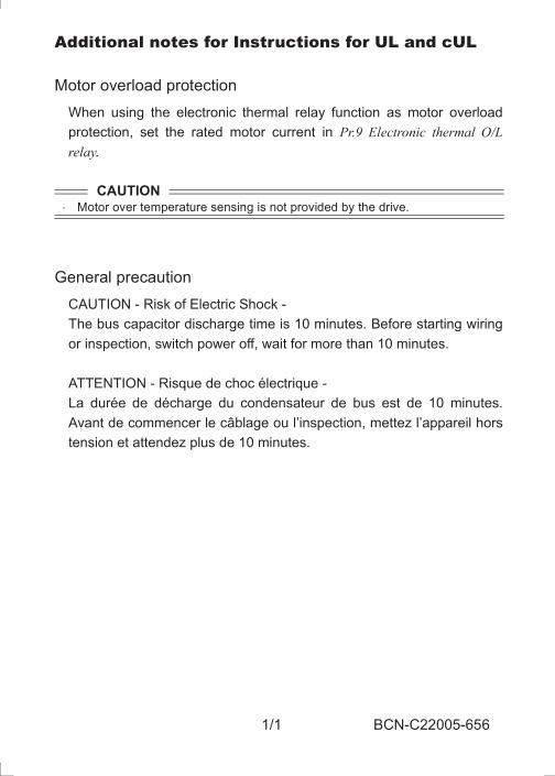
1/1 BCN-C22005-656
Additional notes for Instructions for UL and cUL
Motor overload protection
When using the electronic thermal relay function as motor overload
protection, set the rated motor current in Pr.9 Electronic thermal O/Lrelay.
General precaution
CAUTION - Risk of Electric Shock -
The bus capacitor discharge time is 10 minutes. Before starting wiring
or inspection, switch power off, wait for more than 10 minutes.
ATTENTION - Risque de choc électrique -
La durée de décharge du condensateur de bus est de 10 minutes.
Avant de commencer le câblage ou l’inspection, mettez l’appareil hors
tension et attendez plus de 10 minutes.
CAUTION Motor over temperature sensing is not provided by the drive.
BCN-C22005-656.fm 1 ページ 2013年8月29日 木曜日 午後1時16分
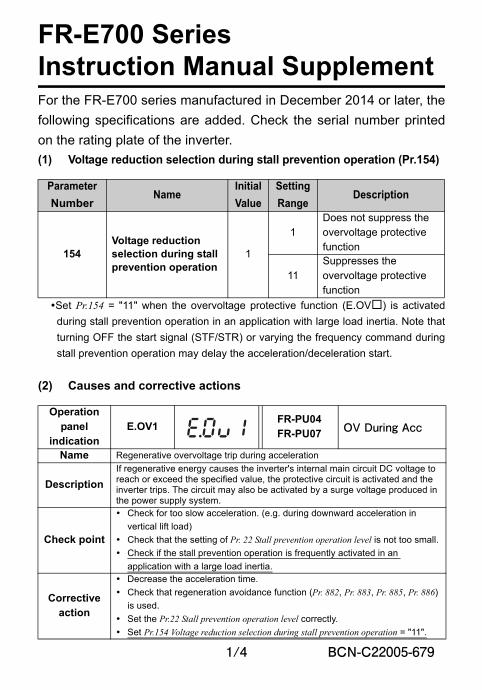
1/4 BCN-C22005-679
FR-E700 SeriesInstruction Manual SupplementFor the FR-E700 series manufactured in December 2014 or later, the
following specifications are added. Check the serial number printed
on the rating plate of the inverter.
(1) Voltage reduction selection during stall prevention operation (Pr.154)
Set Pr.154 = "11" when the overvoltage protective function (E.OV) is activated
during stall prevention operation in an application with large load inertia. Note that
turning OFF the start signal (STF/STR) or varying the frequency command during
stall prevention operation may delay the acceleration/deceleration start.
(2) Causes and corrective actions
Parameter
NumberName
Initial
Value
Setting
RangeDescription
154Voltage reduction selection during stall prevention operation
1
1Does not suppress the overvoltage protective function
11Suppresses the overvoltage protective function
Operation panel
indicationE.OV1
FR-PU04FR-PU07 OV During Acc
Name Regenerative overvoltage trip during acceleration
Description
If regenerative energy causes the inverter's internal main circuit DC voltage to reach or exceed the specified value, the protective circuit is activated and the inverter trips. The circuit may also be activated by a surge voltage produced in the power supply system.
Check point
Check for too slow acceleration. (e.g. during downward acceleration in
vertical lift load)
Check that the setting of Pr. 22 Stall prevention operation level is not too small.
Check if the stall prevention operation is frequently activated in an
application with a large load inertia.
Corrective action
Decrease the acceleration time.
Check that regeneration avoidance function (Pr. 882, Pr. 883, Pr. 885, Pr. 886)
is used.
Set the Pr.22 Stall prevention operation level correctly.
Set Pr.154 Voltage reduction selection during stall prevention operation = "11".
BCN-C22005-679.fm 1 ページ 2014年11月7日 金曜日 午前11時58分
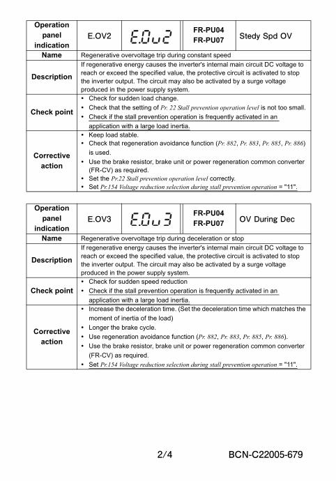
2/4 BCN-C22005-679
Operation panel
indicationE.OV2
FR-PU04FR-PU07 Stedy Spd OV
Name Regenerative overvoltage trip during constant speed
Description
If regenerative energy causes the inverter's internal main circuit DC voltage to reach or exceed the specified value, the protective circuit is activated to stop the inverter output. The circuit may also be activated by a surge voltage produced in the power supply system.
Check point
Check for sudden load change.
Check that the setting of Pr. 22 Stall prevention operation level is not too small.
Check if the stall prevention operation is frequently activated in an
application with a large load inertia.
Corrective action
Keep load stable. Check that regeneration avoidance function (Pr. 882, Pr. 883, Pr. 885, Pr. 886)
is used.
Use the brake resistor, brake unit or power regeneration common converter (FR-CV) as required.
Set the Pr.22 Stall prevention operation level correctly. Set Pr.154 Voltage reduction selection during stall prevention operation = "11".
Operation panel
indicationE.OV3
FR-PU04FR-PU07 OV During Dec
Name Regenerative overvoltage trip during deceleration or stop
Description
If regenerative energy causes the inverter's internal main circuit DC voltage to reach or exceed the specified value, the protective circuit is activated to stop the inverter output. The circuit may also be activated by a surge voltage produced in the power supply system.
Check point Check for sudden speed reduction
Check if the stall prevention operation is frequently activated in an
application with a large load inertia.
Corrective action
Increase the deceleration time. (Set the deceleration time which matches the
moment of inertia of the load)
Longer the brake cycle.
Use regeneration avoidance function (Pr. 882, Pr. 883, Pr. 885, Pr. 886).
Use the brake resistor, brake unit or power regeneration common converter
(FR-CV) as required.
Set Pr.154 Voltage reduction selection during stall prevention operation = "11".
BCN-C22005-679.fm 2 ページ 2014年11月7日 金曜日 午前11時58分
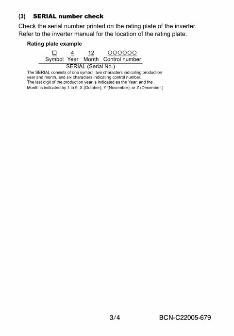
3/4 BCN-C22005-679
(3) SERIAL number checkCheck the serial number printed on the rating plate of the inverter.Refer to the inverter manual for the location of the rating plate.
Rating plate example
4 12 Symbol Year Month Control number
SERIAL (Serial No.)The SERIAL consists of one symbol, two characters indicating production year and month, and six characters indicating control number.The last digit of the production year is indicated as the Year, and the Month is indicated by 1 to 9, X (October), Y (November), or Z (December.)
BCN-C22005-679.fm 3 ページ 2014年11月7日 金曜日 午前11時58分

4/4 BCN-C22005-679
MEMO
BCN-C22005-679.fm 4 ページ 2014年11月7日 金曜日 午前11時58分
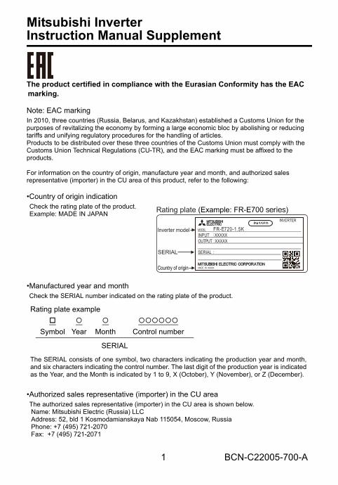
1 BCN-C22005-700-A
Mitsubishi InverterInstruction Manual Supplement
The product certified in compliance with the Eurasian Conformity has the EAC marking.
Note: EAC markingIn 2010, three countries (Russia, Belarus, and Kazakhstan) established a Customs Union for the purposes of revitalizing the economy by forming a large economic bloc by abolishing or reducing tariffs and unifying regulatory procedures for the handling of articles.Products to be distributed over these three countries of the Customs Union must comply with the Customs Union Technical Regulations (CU-TR), and the EAC marking must be affixed to the products.
For information on the country of origin, manufacture year and month, and authorized sales representative (importer) in the CU area of this product, refer to the following:
•Country of origin indication
•Manufactured year and monthCheck the SERIAL number indicated on the rating plate of the product.
•Authorized sales representative (importer) in the CU areaThe authorized sales representative (importer) in the CU area is shown below. Name: Mitsubishi Electric (Russia) LLC Address: 52, bld 1 Kosmodamianskaya Nab 115054, Moscow, Russia Phone: +7 (495) 721-2070 Fax: +7 (495) 721-2071
Check the rating plate of the product.Example: MADE IN JAPAN
Rating plate example
Symbol Year Month Control number
SERIAL
The SERIAL consists of one symbol, two characters indicating the production year and month,and six characters indicating the control number. The last digit of the production year is indicatedas the Year, and the Month is indicated by 1 to 9, X (October), Y (November), or Z (December).
SERIAL
Inverter model MODEL FR-E720-1.5K INPUT XXXXX OUTPUT XXXXX SERIAL
MADE IN XXXXX
INVERTER
PASSED
Country of origin
Rating plate (Example: FR-E700 series)
bcnc22005700.fm 1 ページ 2016年1月6日 水曜日 午後1時39分
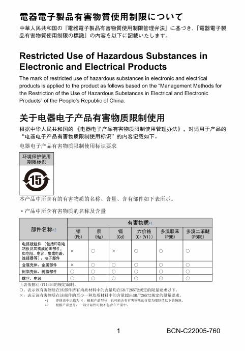
1 BCN-C22005-760
電器電子製品有害物質使用制限について中華人民共和国の『電器電子製品有害物質使用制限管理弁法』に基づき、「電器電子製品有害物質使用制限の標識」の内容を以下に記載いたします。
Restricted Use of Hazardous Substances in Electronic and Electrical ProductsThe mark of restricted use of hazardous substances in electronic and electrical products is applied to the product as follows based on the “Management Methods for the Restriction of the Use of Hazardous Substances in Electrical and Electronic Products” of the People's Republic of China.
关于电器电子产品有害物质限制使用根据中华人民共和国的 《电器电子产品有害物质限制使用管理办法》,对适用于产品的
“电器电子产品有害物质限制使用标识”的内容记载如下。
电器电子产品有害物质限制使用标识要求
本产品中所含有的有害物质的名称、含量、含有部件如下表所示。
·产品中所含有害物质的名称及含量
上表依据SJ/T11364的规定编制。
:表示该有害物质在该部件所有均质材料中的含量均在GB/T26572规定的限量要求以下。
×:表示该有害物质在该部件的至少一种均质材料中的含量超出GB/T26572规定的限量要求。 即使表中记载为 ×,根据产品型号,也可能会有有害物质的含量为限制值以下的情况。
根据产品型号,一部分部件可能不包含在产品中。
环境保护使用期限标识
部件名称
有害物质
铅(Pb)
汞(Hg)
镉(Cd)
六价铬(Cr(VI))
多溴联苯(PBB)
多溴二苯醚(PBDE)
电路板组件 (包括印刷电路板及其构成的零部件,如电阻、电容、集成电路、连接器等)、电子部件
× ×
金属壳体、金属部件 × 树脂壳体、树脂部件 螺丝、电线
bcnc22005760.fm 1 ページ 2016年5月27日 金曜日 午前10時41分
1/2 BCN-C22005-791
FREQROL-E700 シリーズ取扱説明書 追加説明書UL 、 cUL についての注意事項を変更しました。
UL、cULについての注意事項(準拠規格 UL 508C, CSA C22.2 No.14)(1) 据付け盤内使用の製品として認定を取得しています。インバータの周囲温度、湿度、雰囲気が仕様を満足するように盤を設計してください。 分岐回路保護アメリカ合衆国内に設置する場合は分岐回路の保護はNational Electrical Code および現地の規格に従って実施してください。カナダ国内に設置する場合は分岐回路の保護はCanadian Electrical Code および現地の規格に従って実施してください。インバータが装備している短絡保護は、分岐回路を保護するものではありません。また、分岐回路保護用のクラスT、クラスJ、クラスCCタイプのヒューズ以上の遮断速度を持つ適切な定格のUL、cUL認定ヒューズ、もしくはUL489配線用遮断器(MCCB)を選定し、使用してください。
FR-E700 Series Instruction Manual SupplementInstructions for UL and cUL have been revised.
Instructions for UL and cUL(Standard to comply with: UL 508C, CSA C22.2 No. 14)
InstallationThe below types of inverter have been approved as products for use in enclosure and approvaltests were conducted under the following conditions. Design the enclosure so that the surroundingair temperature, humidity and ambience of the inverter will satisfy the above specifications.
Branch Circuit ProtectionIntegral solid state short circuit protection does not provide branch circuit protection. Branch circuitprotection must be provided in accordance with the National Electrical Code for the U.S. or theCanadian Electrical Code for Canada and any additional codes. As specified, UL Class T, Class J,Class CC fuses or any faster acting fuse with the appropriate rating or Listed UL 489 Molded CaseCircuit Breaker (MCCB), or Type E combination motor controller must be employed.
bcnc22005791【向け先別版】.fm 1 ページ 2017年3月29日 水曜日 午後8時20分
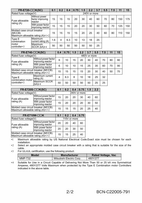
2/2 BCN-C22005-791
Maximum allowable rating by US National Electrical Code.Exact size must be chosen for eachinstallation.
Select an appropriate molded case circuit breaker with a rating that is suitable for the size of thecable.
For UL/cUL certification, use the following product.
Suitable for Use in a Circuit Capable of Delivering Not More Than 50 or 25 kA rms SymmetricalAmperes, 480Y/277 Volts Maximum when protected by the Type E Combination motor Controllersindicated in the above table.
FR-E720-K(SC) 0.1 0.2 0.4 0.75 1.5 2.2 3.7 5.5 7.5 11 15Rated fuse voltage(V) 240V or more
Fuse allowable rating (A)
Without power factor improving reactor
15 15 15 20 30 40 60 70 80 150 175
With power factor improving reactor 15 15 15 20 20 30 50 60 70 125 150
Molded case circuit breaker (MCCB)Maximum allowable rating (A)
15 15 15 15 20 25 40 60 80 110 150
Type E combination motor controller
Maximum current rating (A) 1.6 4 6.3 10 13 18 25
Maximum SCCR (kA) 50 50 50 50 50 50 25
FR-E740-K(SC) 0.4 0.75 1.5 2.2 3.7 5.5 7.5 11 15Rated fuse voltage(V) 480V or more
Fuse allowable rating (A)
Without power factor improving reactor 6 10 15 20 30 40 70 80 90
With power factor improving reactor 6 10 10 15 25 35 60 70 90
Molded case circuit breaker (MCCB)Maximum allowable rating (A) 15 15 15 15 20 30 40 50 70
Type E combination motor controller
Maximum current rating (A) 4 6.3 8 10 18 25 32
Maximum SCCR (kA) 50 50 50 50 50 25 25
FR-E720S-K(SC) 0.1 0.2 0.4 0.75 1.5 2.2Rated fuse voltage(V) 240V or more
Fuse allowable rating (A)
Without power factor improving reactor 15 20 20 30 40 60
With power factor improving reactor 15 20 20 20 30 50
Molded case circuit breaker (MCCB)Maximum allowable rating (A) 15 15 15 20 25 40
FR-E710W-K 0.1 0.2 0.4 0.75Rated fuse voltage(V) 115V or more
Fuse allowable rating (A)
Without power factor improving reactor 20 20 40 60
With power factor improving reactor 20 20 30 50
Molded case circuit breaker (MCCB)Maximum allowable rating (A) 15 15 25 40
Model Manufacturer Rated Voltage, VacMMP-T32 Mitsubishi Electric Corp. 480Y/277
bcnc22005791【向け先別版】.fm 2 ページ 2017年3月29日 水曜日 午後8時20分
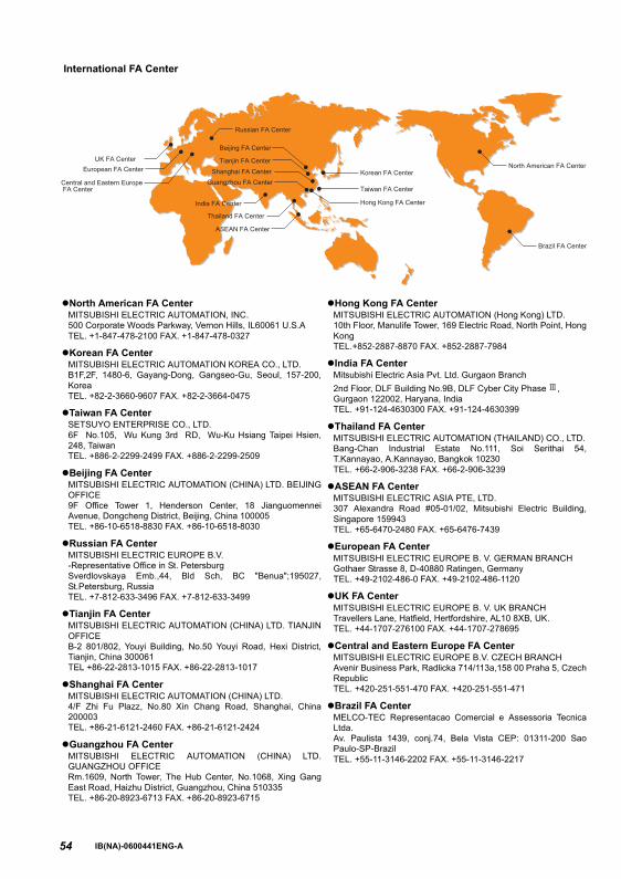
54
International FA Center
Korean FA Center
Beijing FA Center
European FA Center
UK FA Center
Central and Eastern Europe FA Center
Tianjin FA Center
Shanghai FA Center
Guangzhou FA Center
Hong Kong FA Center
Taiwan FA Center
North American FA Center
ASEAN FA Center
Thailand FA Center
India FA Center
Brazil FA Center
Russian FA Center
North American FA CenterMITSUBISHI ELECTRIC AUTOMATION, INC.500 Corporate Woods Parkway, Vernon Hills, IL60061 U.S.ATEL. +1-847-478-2100 FAX. +1-847-478-0327
Korean FA CenterMITSUBISHI ELECTRIC AUTOMATION KOREA CO., LTD.B1F,2F, 1480-6, Gayang-Dong, Gangseo-Gu, Seoul, 157-200,KoreaTEL. +82-2-3660-9607 FAX. +82-2-3664-0475
Taiwan FA CenterSETSUYO ENTERPRISE CO., LTD.6F No.105, Wu Kung 3rd RD, Wu-Ku Hsiang Taipei Hsien,248, TaiwanTEL. +886-2-2299-2499 FAX. +886-2-2299-2509
Beijing FA CenterMITSUBISHI ELECTRIC AUTOMATION (CHINA) LTD. BEIJINGOFFICE9F Office Tower 1, Henderson Center, 18 JianguomenneiAvenue, Dongcheng District, Beijing, China 100005TEL. +86-10-6518-8830 FAX. +86-10-6518-8030
Russian FA CenterMITSUBISHI ELECTRIC EUROPE B.V. -Representative Office in St. PetersburgSverdlovskaya Emb.,44, Bld Sch, BC "Benua";195027,St.Petersburg, RussiaTEL. +7-812-633-3496 FAX. +7-812-633-3499
Tianjin FA CenterMITSUBISHI ELECTRIC AUTOMATION (CHINA) LTD. TIANJINOFFICEB-2 801/802, Youyi Building, No.50 Youyi Road, Hexi District,Tianjin, China 300061TEL +86-22-2813-1015 FAX. +86-22-2813-1017
Shanghai FA CenterMITSUBISHI ELECTRIC AUTOMATION (CHINA) LTD.4/F Zhi Fu Plazz, No.80 Xin Chang Road, Shanghai, China200003TEL. +86-21-6121-2460 FAX. +86-21-6121-2424
Guangzhou FA CenterMITSUBISHI ELECTRIC AUTOMATION (CHINA) LTD.GUANGZHOU OFFICERm.1609, North Tower, The Hub Center, No.1068, Xing GangEast Road, Haizhu District, Guangzhou, China 510335TEL. +86-20-8923-6713 FAX. +86-20-8923-6715
Hong Kong FA CenterMITSUBISHI ELECTRIC AUTOMATION (Hong Kong) LTD.10th Floor, Manulife Tower, 169 Electric Road, North Point, HongKongTEL.+852-2887-8870 FAX. +852-2887-7984
India FA CenterMitsubishi Electric Asia Pvt. Ltd. Gurgaon Branch2nd Floor, DLF Building No.9B, DLF Cyber City Phase ,Gurgaon 122002, Haryana, IndiaTEL. +91-124-4630300 FAX. +91-124-4630399
Thailand FA CenterMITSUBISHI ELECTRIC AUTOMATION (THAILAND) CO., LTD.Bang-Chan Industrial Estate No.111, Soi Serithai 54,T.Kannayao, A.Kannayao, Bangkok 10230TEL. +66-2-906-3238 FAX. +66-2-906-3239
ASEAN FA CenterMITSUBISHI ELECTRIC ASIA PTE, LTD.307 Alexandra Road #05-01/02, Mitsubishi Electric Building,Singapore 159943TEL. +65-6470-2480 FAX. +65-6476-7439
European FA CenterMITSUBISHI ELECTRIC EUROPE B. V. GERMAN BRANCHGothaer Strasse 8, D-40880 Ratingen, GermanyTEL. +49-2102-486-0 FAX. +49-2102-486-1120
UK FA CenterMITSUBISHI ELECTRIC EUROPE B. V. UK BRANCHTravellers Lane, Hatfield, Hertfordshire, AL10 8XB, UK.TEL. +44-1707-276100 FAX. +44-1707-278695
Central and Eastern Europe FA CenterMITSUBISHI ELECTRIC EUROPE B.V. CZECH BRANCHAvenir Business Park, Radlicka 714/113a,158 00 Praha 5, CzechRepublicTEL. +420-251-551-470 FAX. +420-251-551-471
Brazil FA CenterMELCO-TEC Representacao Comercial e Assessoria TecnicaLtda.Av. Paulista 1439, conj.74, Bela Vista CEP: 01311-200 SaoPaulo-SP-BrazilTEL. +55-11-3146-2202 FAX. +55-11-3146-2217
IB(NA)-0600441ENG-A

HEAD OFFICE: TOKYO BUILDING 2-7-3, MARUNOUCHI, CHIYODA-KU, TOKYO 100-8310, JAPAN
MODEL
MODEL
CODE1A2-P25
FR-E700
INSTRUCTION MANUAL (BASIC)
IB(NA)-0600441ENG-A(1012)MEE Printed in Japan Specifications subject to change without notice.