Embed Size (px)
Citation preview
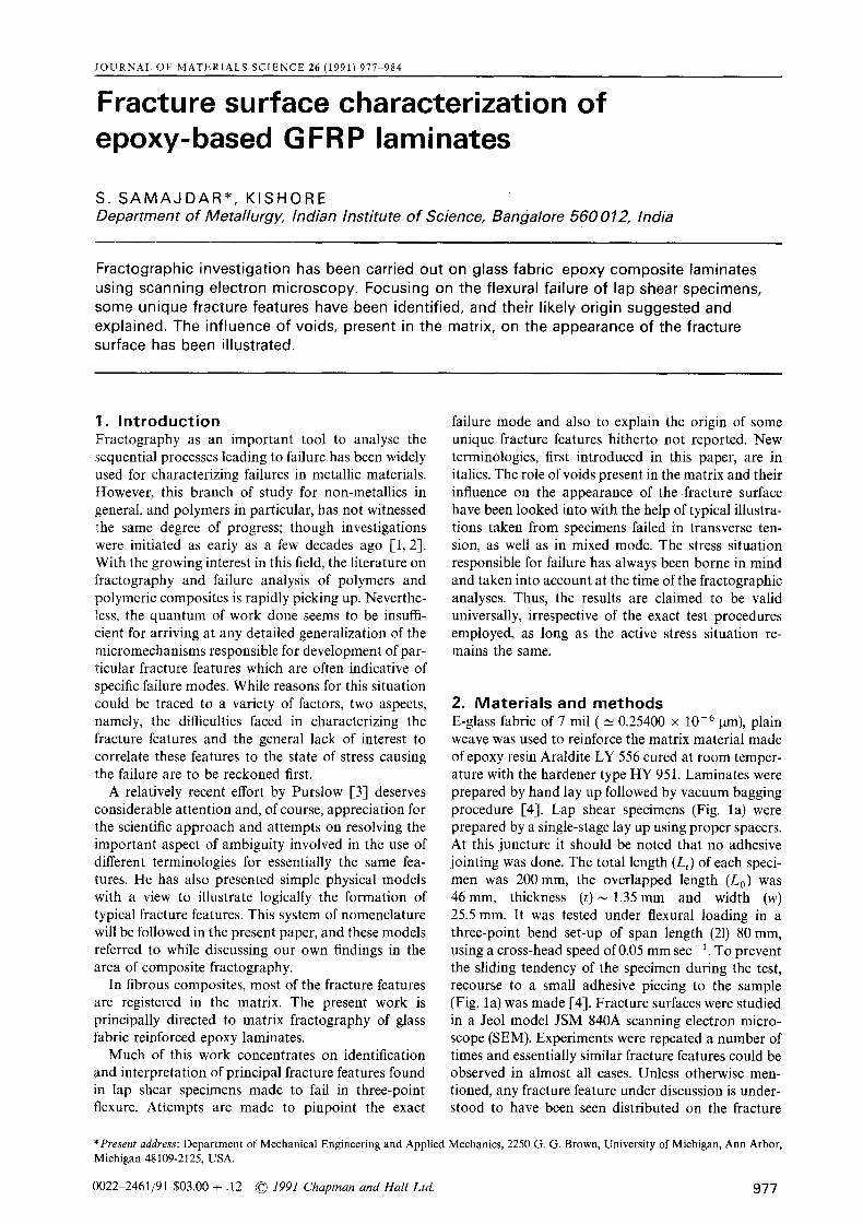
JOURNAL OF MATERIALS SCIENCE 26 (1991) 977 984
Fracture surface characterization of epoxy-based GFRP laminates
S. S A M A J D A R * , KISHORE Department of Metallurgy, Indian Institute of Science, Bangalore 560 012, India
Fractographic investigation has been carried out on glass fabric-epoxy composite laminates using scanning electron microscopy. Focusing on the flexural failure of lap shear specimens, some unique fracture features have been identified, and their likely origin suggested and explained. The influence of voids, present in the matrix, on the appearance of the fracture surface has been illustrated.
1. I n t r o d u c t i o n Fractography as an important tool to analyse the sequential processes leading to failure has been widely used for characterizing failures in metallic materials. However, this branch of study for non-metallics in general, and polymers in particular, has not witnessed the same degree of progress; though investigations were initiated as early as a few decades ago [1, 2]. With the growing interest in this field, the literature on fractography and failure analysis of polymers and polymeric composites is rapidly picking up. Neverthe- less, the quantum of work done seems to be insuffi- cient for arriving at any detailed generalization of the micromechanisms responsible for development of par- ticular fracture features which are often indicative of specific failure modes. While reasons for this situation could be traced to a variety of factors, two aspects, namely, the difficulties faced in characterizing the fracture features and the general lack of interest to correlate these features to the state of stress causing the failure are to be reckoned first.
A relatively recent effort by Purslow [3] deserves considerable attention and, of course, appreciation for the scientific approach and attempts on resolving the important aspect of ambiguity involved in the use of different terminologies for essentially the same fea- tures. He has also presented simple physical models with a view to illustrate logically the formation of typical fracture features. This system of nomenclature will be followed in the present paper, and these models referred to while discussing our own findings in the area of composite fractography.
In fibrous composites, most of the fracture features are registered in the matrix. The present work is principally directed to matrix fractography of glass fabric reinforced epoxy laminates.
Much of this work concentrates on identification and interpretation of principal fracture features found in lap shear specimens made to fail in three-point flexure. Attempts are made to pinpoint the exact
failure mode and also to explain the origin of some unique fracture features hitherto not reported. New terminologies, first introduced in this paper, are in italics. The role of voids present in the matrix and their influence on the appearance of the fracture surface have been looked into with the help of typical illustra- tions taken from specimens failed in transverse ten- sion, as well as in mixed mode. The stress situation responsible for failure has always been borne in mind and taken into account at the time of the fractographic analyses. Thus, the results are claimed to be valid universally, irrespective of the exact test procedures employed, as long as the active stress situation re- mains the same.
2. Mater ia ls and methods E-glass fabric of 7 mil ( _~ 0.25400 x 10⁻⁶ ~tm), plain weave was used to reinforce the matrix material made of epoxy resin Araldite LY 556 cured at room temper- ature with the hardener type HY 951. Laminates were prepared by hand lay up followed by vacuum bagging procedure [4]. Lap shear specimens (Fig. la) were prepared by a single-stage lay up using proper spacers. At this juncture it should be noted that no adhesive jointing was done. The total length (Lt) of each speci- men was 200 mm, the overlapped length (Lo) was 46mm, thickness ( t )~ 1.35mm and width (w) 25.5 mm. It was tested under flexural loading in a three-point bend set-up of span length (21) 80 mm, using a cross-head speed of 0.05 mm sec- 1. To prevent the sliding tendency of the specimen during the test, recourse to a small adhesive piecing to the sample (Fig. la) was made [4]. Fracture surfaces were studied in a Jeol model JSM 840A scanning electron micro- scope (SEM). Experiments were repeated a number of times and essentially similar fracture features could be observed in almost all cases. Unless otherwise men- tioned, any fracture feature under discussion is under- stood to have been seen distributed on the fracture
* Present address: Department of Mechanical Engineering and Applied Mechanics, 2250 G. G. Brown, University of Michigan, Ann Arbor, Michigan 48109-2125, USA.
0022-2461/91 $03.00 + .12 �9 1991 Chapman and Hall Ltd. 9 7 7

PIZi p/z L0 q A ,esiv,• tNI jQ piece
I Q'I IP LStarter notch .
(a) Lt
z y
'b'
~ xzz.~.~
c:l ' ~ 5' Figure 1 Illustrations of(a) geometry and loading configuration, (b) failure pattern, and (c) the state of stress ahead of the advancing failure front (O) of the tap shear specimen. XY is the plane of iamination.
surface of both the separating halves of the failed lap shear specimen.
In this paper the term "axial" has been used to indicate the direction of the long axis of the test specimen. Care was taken during specimen prepar- ation to ensure that the warp fibres were always oriented along the axial direction.
3. Results and discussion When subjected to three-point flexural loading (Fig. la), apparently the lap shear specimen may be expected to fail in shear along the plane QQ'. Assum- ing simple bending, the state of stress operative there may be thought to be pure shear, because this plane is located exactly at the mid thickness position of the
overlapped section. That a shear field was active in effecting the interlaminar failure along QQ' was evid- ent from the common occurrence of shear cusps [3] in the interfibre matrix regions of the fracture surface. (Whenever required, the overall fracture direction has been indicated on the illustrations by means of an arrowhead, -*, while the broken arrow,----, and the half arrow, ~,-~-, have been used to indicate the direction of local crack/fracture propagation and active shear stress respectively.) Although lacking sharpnessat this high magnification, Fig. 2a is significant for docu- menting one such cusp formation just at the point of inception. But the myriad of rivers present at the resin- rich portions of the fracture surface, bore testimony to the existence of a tensile (transverse) stress too, in action at the failure front. It is to be appreciated that an intermediate configuration of the specimen during the failure process can be represented schematically as shown in Fig. lb. Evidently, the bending action as shown introduces an axial tensile stress, 02, along the crack face OS'. An exaggerated view (shown schemati- cally in Fig. lc) of the crack tip region is helpful in understanding the actual state of stress operative there. Although the bending action introduces only axial stress, in reality, because of the well known "notch effect" I-5] operative at the crack tip, a trans- verse tensile stress (crz) comes into play. It is this cr~ that has actually caused the development of tensile failure features, like rivers, on the fracture surface. Further, the lower face OS' bends more than the upper face OQ. This would tend to effect a strain difference between these two faces, resulting in the development of a shear stress, Xxz, active at the crack tip O. The occurrence of shear cusps in the interfibre matrix owes its origin to this xx~ only. The deduction, based on fractographic evidence, that lap shear specimens under flexure actually fail in the mixed mode, is thus upheld by a qualitative analysis of the state of stress active at the progressing failure front. Further, the failure scheme envisioned (Fig. lb) strongly suggests a peel type of fracture [3]. And in fact, the occurrence of typical peel fracture features like tied zones were quite common on the fracture surface (Fig. 2b).
Now, that the flexural failure has been classified and confirmed as peel type, occurrence of well-developed
Figure 2 SEM fractographs from lap shear specimen failed in flexure illustrating (a) incipient cusp and (b) tied zones.
978
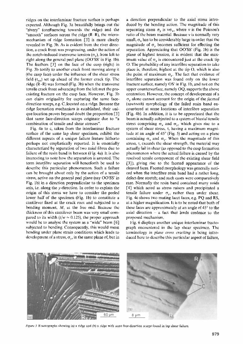
ridges on the interlaminar fracture surface is perhaps expected. Although Fig. 3a beautifully brings out the "rivery" (confluencing towards the ridge) and the "smooth" surfaces across the ridge (R-R), the micro- mechanism of ridge formation [3] is more clearly revealed in Fig. 3b. As is evident from the river direc- tion, a crack front was progressing, under the action of the notch-induced transverse tension (~) , from left to right along the general peel plane (OO'SS' in Fig. lb). The feathers [3] on the face of the cusp (right) in Fig. 3b testify to another crack front moving along it (the cusp face) under the influence of the shear stress field ( ~ ) set up ahead of the former crack tip. The ridge (R-R) was formed (Fig. 3b) when the transverse tensile crack front advancing from the left met the pre- existing fracture on the cusp face. However, Fig. 3b can claim originality for capturing the same face- direction scarps, e.g. C, located on a ridge. Because the ridge formation mechanism is established, their uni- que location proves beyond doubt the proposition [31 that same face-direction scarps originate due to "a combination of tensile and shear stresses".
Fig. 4a to c, taken from the interlaminar fracture surface of the same lap shear specimen, exhibit the different aspects of a unique failure feature hitherto perhaps not emphatically reported. It is essentially characterized by separation of two axial fibres due to failure of the resin band in between (Fig. 4a). It is also interesting to note how the separation is arrested. The term interfibre separation will henceforth be used to describe this particular phenomenon. Such a failure can be brought about only by the action of a tensile stress, active on the general peel plane (say OO'SS' in Fig. lb) in a direction perpendicular to the specimen axis, i.e. along the y-direction. In order to explain the origin of this stress we have to consider the peeled lower half of the specimen (Fig. lb) to constitute a cantilever fixed at the crack root and subjected to a bending moment, M, at the free end. Because the thickness of this cantilever beam was very small com- pared to its width (t/w ~- 0.125), the proper approach would be to analyse the system as a "wide" beam [6] subjected to bending. Consequently, this would mean bending under plane strain conditions which leads to development of a stress, cyy, in the same plane of, but in
a direction perpendicular to the axial stress intro- duced by the bending action. The magnitude of this separating stress cyy is vcy x, where v is the Poisson's ratio of the beam material. Because v is normally very small, cy~ has to be considerably large in order that the magnitude of c~y becomes sufficient for effecting the separation. Appreciating that OO'SS' (Fig. lb) is the plane of highest tension, it is evident that the max- imum value of ~x is encountered just at the crack tip O. The probability of any interfibre separation to take place is, therefore, highest at the tip O, which is also the point of maximum ~y. The fact that evidence of interfibre separation was found only on the lower fracture surface, namely OS' in Fig. lb, and not on the upper countersurface, namely OQ, supports the above contention. However, the concept of development of a c~y alone cannot account for the origin of the faceted (sawtooth) morphology of the failed resin band en- countered at some locations of interfibre separation (Fig. 4b). In addition, it is to be appreciated that the beam is actually subjected to a system of biaxial tensile stress comprising cy x and c~y, which gives rise to a system of shear stress, z, having a maximum magni- tude at an angle of 45 ~ (Fig. 5) and acting on a plane containing cy x and cyy. When the magnitude of this stress, x, exceeds the shear strength, the material may actually fail in shear (as opposed to the cusp formation phenomenon where the actual failure is caused by the resolved tensile component of the existing shear field [3]), giving rise to the faceted appearance of the cleaved faces. Faceted morphology was generally noti- ced when the interfibre resin band had a rather long, defect-free stretch; and such cases were comparatively rare. Normally the resin band contained many voids [4] which acted as stress raisers and precipitated a tensile failure under ~y, rather than under shear. Fig. 4c shows two mating facet faces, e.g. PQ and RS, at a higher magnification. It is to be noted that both of these faces are approximately at an angle of 45 ~ to the axial direction - a fact that lends credence to the proposed mechanism.
Fig. 6 displays another unique interlaminar fracto- graph encountered in the lap shear specimen. The terminology in plane cross crackin9 is being intro- duced here to describe this particular aspect of failure,
Figure 3 Fractographs showing (a) a ridge and (b) a ridge with same face-direction scarps found in lap shear failure.
979
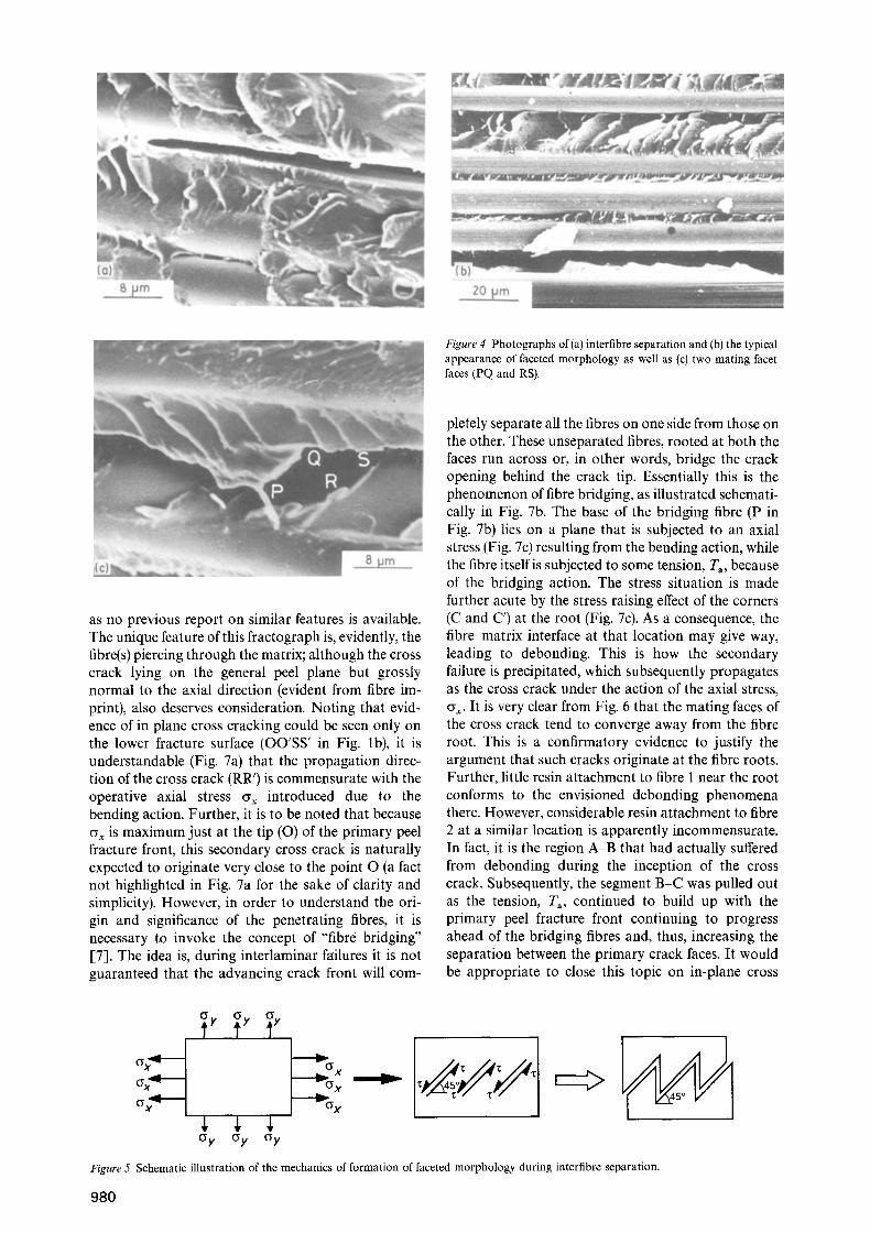
Figure 4 Photographs of(a) interfibre separation and (b) the typical appearance of faceted morphology as well as (c) two mating facet faces (PQ and RS).
as no previous report on similar features is available. The unique feature of this fractograph is, evidently, the fibre(s) piercing through the matrix; although the cross crack lying on the general peel plane but grossly normal to the axial direction (evident from fibre im- print), also deserves consideration. Noting that evid- ence of in plane cross cracking could be seen only on the lower fracture surface (OO'SS' in Fig. lb), it is understandable (Fig. 7a) that the propagation direc- tion of the cross crack (RR') is commensurate with the operative axial stress ~x introduced due to the bending action. Further, it is to be noted that because c~x is maximum just at the tip (O) of the primary peel fracture front, this secondary cross crack is naturally expected to originate very close to the point O (a fact not highlighted in Fig. 7a for the sake of clarity and simplicity). However, in order to understand the ori- gin and significance of the penetrating fibres, it is necessary to invoke the concept of "fibre bridging" [7]. The idea is, during interlaminar failures it is not guaranteed that the advancing crack front will com-
pletely separate all the fibres on one side from those on the other. These unseparated fibres, rooted at both the faces run across or, in other words, bridge the crack opening behind the crack tip. Essentially this is the phenomenon of fibre bridging, as illustrated schemati- cally in Fig. 7b. The base of the bridging fibre (P in Fig. 7b) lies on a plane that is subjected to an axial stress (Fig. 7c) resulting from the bending action, while the fibre itself is subjected to some tension, Ta, because of the bridging action. The stress situation is made further acute by the stress raising effect of the corners (C and C') at the root (Fig. 7c). As a consequence, the fibre-matrix interface at that location may give way, leading to debonding. This is how the secondary failure is precipitated, which subsequently propagates as the cross crack under the action of the axial stress, cy x. It is very clear from Fig. 6 that the mating faces of the cross crack tend to converge away from the fibre root. This is a confirmatory evidence to justify the argument that such cracks originate at the fibre roots. Further, little resin attachment to fibre 1 near the root conforms to the envisioned debonding phenomena there. However, considerable resin attachment to fibre 2 at a similar location is apparently incommensurate. In fact, it is the region A-B that had actually suffered from debonding during the inception of the cross crack. Subsequently, the segment B-C was pulled out as the tension, Ta, continued to build up with the primary peel fracture front continuing to progress ahead of the bridging fibres and, thus, increasing the separation between the primary crack faces. It would be appropriate to close this topic on in-plane cross
5y ~y ~y
G x
Figure 5 Schematic illustration of the mechanics of formation of faceted morphology during interflbre separation.
980

Figure 6 SEM fractograph illustrating in-plane cross cracking in lap shear failure.
~ M R~ S
( 0-~.
7
7 a
(c)
Figure 7 Schematic illustrations of (a) in-plane cross crack (RR') formation during flexural failure of a lap shear specimen, (b) fibre bridging [7], and (c) debonding at the root (P of Fig. 7b) of a bridging fibre. XY is the plane of lamination.
cracking with the comment that it is believed [7] that the phenomenon of fibre bridging "causes an elevation in the measured interlaminar fracture energy" and we do actually see now that the in-plane cross cracking can constitute a potential energy absorbing mech- anism that may be responsible for this enhancement.
The next fractograph (Fig. 8) is from a specimen failed in transverse tension. In view of the overall
Figure 8 Scanning electron micrographs showing wavy pattern.
direction of progress of the interlaminar failure front, the wavy nature of Fig. 8 suggests that the failure marks (e.g. Q) on the resin bands (elevations) located in between two fibres exhibit a distinct "phase lag" with respect to the failure marks (e.g. P) visible on the fibre imprints (depressions). The implication is, adhe- sive failure fronts [8-1 tended to advance faster than the neighbouring cohesive failure fronts; and the rela- tive weakness of the adhesive bond between the fibre and the resin might have been the reason for it.
The presence of a three-dimensional defect in the form of a void inside a stressed solid is known to introduce a stress raising effect around it. The stress is maximum at the edge of the discontinuity, its intensity failing off as one moves away from the edge. The plethora of failure features concentrated in the vicinity of a void is perhaps the reflection of this effect pro- jected on to fractographic evidence. In Fig. 9a, taken from a specimen failed in transverse tension, the con- centration of failure features, mainly rivers directed outwardly, testifies to local crack fronts in the neigh- bourhood progressing away from the void. Note that the void is large and deep enough to reveal the impression of fibres belonging to the lamina beneath the fracture plane. There are, however, two principal features to be observed in this fractograph, namely, the curved lines (e.g. PQR) toward the left and the finger-like pattern [3] just below the void, diverging away from it. A magnified view (Fig. 9b) of the latter clearly reveals how the fracture progressed locally, with a curvilinear crack front indicated by MN. It is also interesting to note how some of these finger-like features develop into a river form before terminating at the regions of fibre-matrix interface. Fig. 9c is noteworthy for capturing these features originating just at the edge of this void. It is known that crack fronts always try to reach a free surface via the shortest route. This micrograph remarkably brings it out by demonstrating how crack fronts close enough to the edge of the void (finding it energetically favour- able) took a turn and terminated into that void, from which it had originated. To behave in a similar fash- ion, crack fronts located (and also directed) away from the void edge would be required to suffer a rather severe bend, which was obviously not favoured; and
981
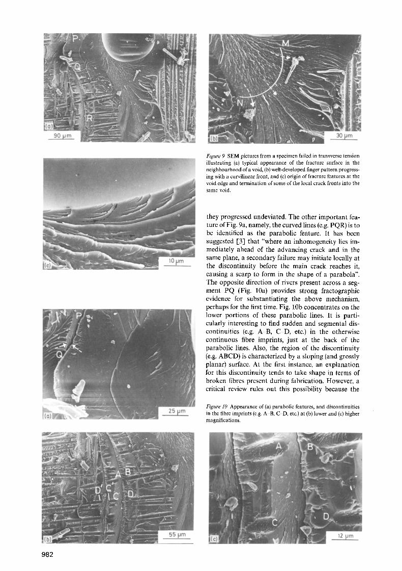
Figure 9 SEM pictures from a specimen failed in transverse tension illustrating (a) typical appearance of the fracture surface in the neighbourhood of a void, (b) well-developed finger pattern progress- ing with a curvilinear front, and (c) origin of fracture features at the void edge and termination of some of the local crack fronts into the same void.
they progressed undeviated. The other important fea- ture of Fig. 9a, namely, the curved lines (e.g. PQR) is to be identified as the parabolic feature. It has been suggested [3] that "where an inhomogeneity lies im- mediately ahead of the advancing crack and in the same plane, a secondary failure may initiate locally at the discontinuity before the main crack reaches it, causing a scarp to form in the shape of a parabola". The opposite direction of rivers present across a seg- ment PQ (Fig. 10a) provides strong fractographic evidence for substantiating the above mechanism, perhaps for the first time. Fig. 10b concentrates on the lower portions of these parabolic lines. It is parti- cularly interesting to find sudden and segmental dis- continuities (e.g. A-B, C-D, etc.) in the otherwise continuous fibre imprints, just at the back of the parabolic lines. Also, t he region of the discontinuity (e.g. ABCD) is characterized by a sloping (and grossly planar) surface. At the first instance, an explanation for this discontinuity tends to take shape in terms of broken fibres present during fabrication. However, a critical review rules out this possibility because the
Figure 10 Appearance of (a) parabolic features, and discontinuities in the fibre imprints (e.g. A B, C-D, etc.) at (b) lower and (c) higher magnifications.
982
'. "'. "':-. . ".: : Rd io �9 i ' "i" " " �9 . ': :
". : ' : ' . " . . ' . . " . ' i : . ' . ' . ." - . ' : ' ' . : ".'."
(a) (b)
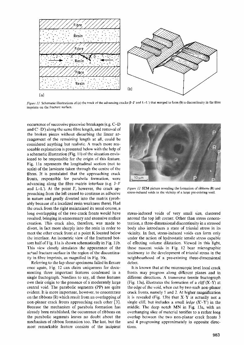
Figure I1 Schematic illustrations of(a) the track of the advancing cracks (J-J' and L-L') that merged to form (b) a discontinuity in the fibre imprints on the fracture surface.
occurrence of successive piecewise breakages (e.g. C-D and C'-D') along the same fibre length, and removal of the broken pieces without disturbing the linear ar- rangement of the remaining length at all, could be considered anything but realistic. A much more rea- sonable explanation is presented below with the help of a schematic illustration (Fig. 11) of the situation envis- ioned to be responsible for the origin of this feature. Fig. l la represents the longitudinal section (not to scale) of the laminate taken through the centre of the fibres. It is postulated that the approaching crack fronts, responsible for parabola formation, were advancing along the fibre-matrix interface (e.g. J-J ' and L-L'). At the point J', however, the crack ap- proaching from the left ceased to continue as adhesive in nature and gently diverted into the matrix (prob- ably because of a localized resin weakness there). Had the crack from the right maintained its usual course, a long overlapping of the two crack fronts would have resulted, bringing in unnecessary and excessive surface creation. This crack also, therefore, was made to divert, in fact more sharply into the resin in order to meet the other crack front at a point K located below the interface. An isometric view of the fractured bot- tom half of Fig. 11 a is shown schematically in Fig. 1 lb. This view closely simulates the appearance of the actual fracture surface in the region of the discontinu- ity in fibre imprints, as magnified in Fig. 10c.
Referring to the lap shear specimens failed in flexure once again, Fig. 12 can claim uniqueness for docu- menting three important features condensed in a single fractograph. Needless to say, all these features owe their origin to the presence of a moderately large central void. The parabolic segments (PP) are quite evident. It is more important, however, to concentrate on the ribbons (R) which result from an overlapping of non-planar crack fronts approaching each other [3]. Because the mechanism of parabola formation has already been established, the occurrence of ribbons on the parabolic segments leaves no doubt about the mechanism of ribbon formation too. The last, but the most remarkable feature consists of the incipient
Figure 12 SEM picture revealing the formation of ribbons (R) and stress-induced voids in the vicinity of a large pre-existing void.
stress-induced voids of very small size, clustered around the top left corner. Other than stress concen- tration, a three-dimensional discontinuity in a stressed body also introduces a state of triaxial stress in its vicinity. In fact, stress-induced voids can form only under the action of hydrostatic tensile stress capable of effecting volume dilatation. Viewed in this light, these nascent voids in Fig. 12 bear micrographic testimony to the development of triaxial stress in the neighbourhood of a pre-existing three-dimensional defect.
It is known that at the microscopic level local crack fronts may progress along different planes and in different directions. A transverse tensile fractograph (Fig. 13a), illustrates the formation of a cliff (X-Y) at the edge of the void, when cut by two such non-planar crack fronts, namely 1 and 2. At higher magnification it is revealed (Fig. 13b) that X-Y is actually not a single cliff, but includes a small ledge (X'-Y') in the middle. The deep notch MN in Fig. 13a, with an overhanging slice of material testifies to a rather long overlap between the two non-planar crack fronts 3 and 4 progressing approximately in opposite direc- tions.
983
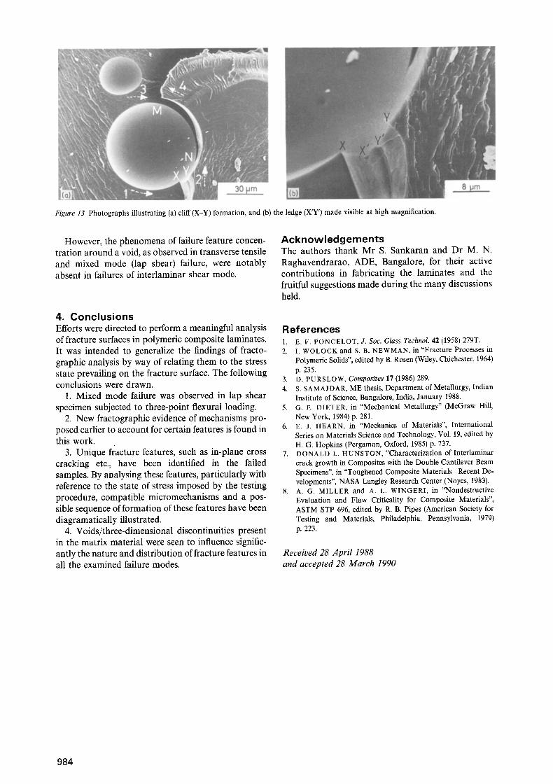
Figure 13 Photographs illustrating (a) cliff (X-Y) formation, and (b) the ledge (X'Y') made visible at high magnification.
However, the phenomena of failure feature concen- tration around a void, as observed in transverse tensile and mixed mode (lap shear) failure, were notably absent in failures of interlaminar shear mode.
4. Conclusions Efforts were directed to perform a meaningful analysis of fracture surfaces in polymeric composite laminates. It was intended to generalize the findings of fracto- graphic analysis by way of relating them to the stress state prevailing on the fracture surface. The following conclusions were drawn.
1. Mixed mode failure was observed in lap shear specimen subjected to three-point flexural loading.
2. New fractographic evidence of mechanisms pro- posed earlier to account for certain features is found in this work.
3. Unique fracture features, such as in-plane cross cracking etc., have been identified in the failed samples. By analysing these features, particularly with reference to the state of stress imposed by the testing procedure, compatible micromechanisms and a pos- sible sequence of formation of these features have been diagramatically illustrated.
4. Voids/three-dimensional discontinuities present in the matrix material were seen to influence signific- antly the nature and distribution of fracture features in all the examined failure modes.
Acknowledgements The authors thank Mr S. Sankaran and Dr M. N. Raghavendrarao, ADE, Bangalore, for their active contributions in fabricating the laminates and the fruitful suggestions made during the many discussions held.
References 1. E.F. PONCELOT, J. Soc. Glass Technol. 42 (1958) 279T. 2. I. WOLOCK and S. B. NEWMAN, in "Fracture Processes in
Polymeric Solids", edited by B. Rosen (Wiley, Chichester, 1964) p. 235.
3. D. PURSLOW, Composites 17 (1986) 289. 4. S. SAMAJDAR, ME thesis, Department of Metallurgy, Indian
Institute of Science, Bangalore, India, January 1988. 5. G.E. DIETER, in "Mechanical Metallurgy" (McGraw Hill,
New York, 1984) p. 281. 6. E. J. HEARN, in "Mechanics of Materials", International
Series on Materials Science and Technology, Vol. 19, edited by H. G. Hopkins (Pergamon, Oxford, 1985) p. 737.
7. DONALD L. HUNSTON, "Characterization of Interlaminar crack growth in Composites with the Double Cantilever Beam Specimens", in "Toughened Composite Materials-Recent De- velopments", NASA Langley Research Center (Noyes, 1983).
8. A. G. MILLER and A. L. WINGERI, in "Nondestructive Evaluation and Flaw Criticality for Composite Materials", ASTM STP 696, edited by R. B. Pipes (American Society for Testing and Materials, Philadelphia, Pennsylvania, 1979) p. 223.
Received 28 April 1988 and accepted 28 March 1990
984


![GFRP [Resin Infusion]](https://img.pdfslide.net/doc/110x75/546e67d4af795971298b5642/gfrp-resin-infusion.jpg)
![Effect of stacking sequence on the flexural and fracture ...125-128]-06.pdf · 125 Effect of stacking sequence on the flexural and fracture properties of carbon/basalt/epoxy hybrid](https://img.pdfslide.net/doc/110x75/5abb1a8f7f8b9a321b8c7363/effect-of-stacking-sequence-on-the-flexural-and-fracture-125-128-06pdf125.jpg)