Embed Size (px)
Citation preview
IOSR Journal of Mechanical and Civil Engineering (IOSR-JMCE)
e-ISSN: 2278-1684,p-ISSN: 2320-334X, Volume 8, Issue 6 (Sep. - Oct. 2013), PP 47-52 www.iosrjournals.org
www.iosrjournals.org 47 | Page
Experimental Test on Gfrp-Epoxy Composite Laminate for
Mechanical, Chemical & Thermal Properties
Jatoth Prudhvi Raj Naik 1, B.Mahasenadhipathi Rao2 & B.Shiva Sambi Reddy 3 1 [M.Tech (CAD/CAM) final year student, Department of mechanical engineering, Sree nidhi institute of
science & technology (Autonomous), Hyderabad, Andhra Pradesh, India.]
2[Assistant professor, Department of mechanical engineering, Sree nidhi institute of science & Technology
(Autonomous), Hyderabad]
3 [Supervisor, managing director, Paru engineers Pvt ltd, phase-1, Cherlapally, Hyderabad, Andhra Pradesh,
India.]
Abstract: GFRP (glass fibre reinforced plastic) composite materials are used in many engineering applications
because of its high strength to weight ratio. The purpose of this experiment is to investigate mechanical, chemical and thermal properties of GFRP rotor blades which are used in cooling towers. These blades are
manufactured by pressure bag moulding process by using suitable mould. Before installation (Delivery), the
blade must be tested for mechanical, chemical, thermal and other properties. For this testing, GFRP laminate is
made by hand layup technique. Epoxy resin is used as matrix in manufacturing of the gfrp laminate.
Key words: GFRP composite laminate, hand layup technique, mechanical properties, chemical resistance,
thermal properties.
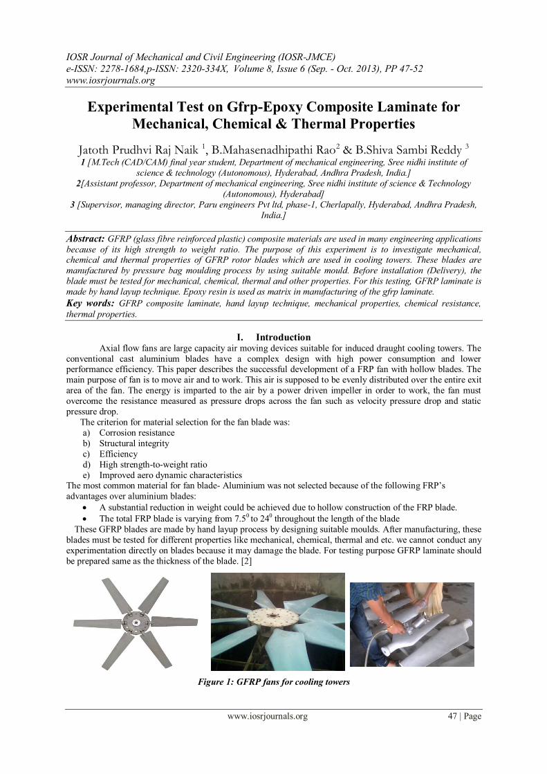
I. Introduction Axial flow fans are large capacity air moving devices suitable for induced draught cooling towers. The
conventional cast aluminium blades have a complex design with high power consumption and lower performance efficiency. This paper describes the successful development of a FRP fan with hollow blades. The
main purpose of fan is to move air and to work. This air is supposed to be evenly distributed over the entire exit
area of the fan. The energy is imparted to the air by a power driven impeller in order to work, the fan must
overcome the resistance measured as pressure drops across the fan such as velocity pressure drop and static
pressure drop.
The criterion for material selection for the fan blade was:
a) Corrosion resistance
b) Structural integrity
c) Efficiency
d) High strength-to-weight ratio
e) Improved aero dynamic characteristics The most common material for fan blade- Aluminium was not selected because of the following FRP‟s
advantages over aluminium blades:
A substantial reduction in weight could be achieved due to hollow construction of the FRP blade.
The total FRP blade is varying from 7.50 to 240 throughout the length of the blade
These GFRP blades are made by hand layup process by designing suitable moulds. After manufacturing, these
blades must be tested for different properties like mechanical, chemical, thermal and etc. we cannot conduct any
experimentation directly on blades because it may damage the blade. For testing purpose GFRP laminate should
be prepared same as the thickness of the blade. [2]
Figure 1: GFRP fans for cooling towers

Experimental Test On Gfrp-Epoxy Composite Laminate For Mechanical, Chemical & Thermal
www.iosrjournals.org 48 | Page
II. Literature Review The word composite in the term composite material signifies that two or more materials are combined on a
macroscopic scale to form a useful third material. The key is the macroscopic examination of a material where
in the components can be identified by the naked eye. Different materials can be combined on a microscopic
scale, such as in alloying of metals, but the resulting material is, for all practical purposes macroscopically
homogeneous, i.e., the components cannot be distinguished by the naked eye and essentially act together. The
advantage of composite material is that, if will designed, they usually exhibit the best qualities of their
components or constituents and often some qualities that neither constituent possesses. Some of the properties
that can be improved by forming a composite material are: [1]
Strength
Stiffness
Corrosion resistance Wear resistance
Acoustical insulation
Weight
Temperature-dependent behaviour
Thermal insulation
Thermal conductivity
Classification of FRP composite materials Classification of FRP composite materials into four broad categories has been done according to the matrix
used. They are
Polymer matrix composites
Metal matrix composites
Ceramic matrix composites and
Carbon /Carbon composites.
Polymer matrix composites are made of thermoplastic or thermo set resins reinforced with fibres such as
glass, carbon etc.
Metal matrix composites consist of a matrix of metals or alloys reinforced with metal fibres such as boron or
carbon. Ceramic matrix composites consist of ceramic matrices reinforced with ceramic fibres such as silicon
carbide, alumina or silicon nitride. They are mainly effective for high temperature applications.
Carbon/carbon composites consist of graphite carbon matrix reinforced with graphite fibres.
III. Hand Layup Process For Glass Fibre PREPARATION OF THE MOLD: Remove dust and dirt from mold. If mold is of plaster, wood, or new
fiberglass, apply soft wax and buff with soft towel. Spray or brush with PVA, parting compound and allow drying. If mold material is glass, metal, ceramic, or well-cured fiberglass, apply three coats of hard wax,
carnauba type, buffing between each coat.
APPLYING THE GEL-COAT: If gel-coat is to be brushed on, allow first coat to cure and then apply the
second coat to make sure that there should be no light spots. If gel-coat is to be sprayed on with a gel-coat gun,
spray up to a thickness of .015” to 020”. When gel-coat has cured long enough that your fingernail cannot easily
scrape it free (test at edge of mold where damage will not show on part) then proceed with next step.
LAY-UP SKIN COAT: Cut ¾ or 1 oz. mat to cover part. Brush catalyzed resin over gel-coat then applies the
mat. Work with roller adding more resin where necessary until all white areas in mat fibers have disappeared
and all air bubbles have escaped. Resin-rich areas weaken the part. Where rollers will not reach, brushes must be
used. When this step is complete, clean all tools in acetone. Allow skin coat to cure before next step.
LAYING FIBERGLASS REINFORCEMENT: For a 12 ft. boat, two layers of 1½ oz. or 2 oz. mat may be adequate, depending upon design. For a 14 ft. boat, an additional layer of woven roving will add considerable
strength. Apply each layer as in step 3, but it will not be necessary to wait for curing between these layers. Be
sure to shake all acetone out of brushes and rollers before applying resin. Acetone drips can result in uncured
spots in the lay-up.
TRIM: On a small lay-up, the fiberglass laminate which hangs over the edge of the mold can be trimmed off
easily with a razor knife if you catch the “trim stage,” of the period after the lay-up has gelled but before it has
hardened. On a larger lay-up, it can be trimmed with a saber saw and coarse sand paper.
CURE: Cure may take from two hours to overnight, depending upon turnover desired, temperature,
canalization, and nature of the part. If laid up in a female mold, longer cure will affect shrinkage and easier
parting. In the case of the male mold, the part comes off more easily before it shrinks appreciably. If the part is

Experimental Test On Gfrp-Epoxy Composite Laminate For Mechanical, Chemical & Thermal
www.iosrjournals.org 49 | Page
subject to warping, a longer cure may be necessary. In any case, when the part is removed it should be supported
in its desired shape until fully cured.
REMOVE PART FROM MOLD: First, examine the trim edge all the way around the mold and make sure
there is no resin bridging the line between the mold and the part. Sand this edge where necessary. Then wooden
wedges, such as “tongue sticks,” can be pushed into the edges to start the separation. Continue separation by
pulling and flexing. In some cases it is necessary to drill a small hole in the mold and apply air or water
pressure.
FINISH: Trim edges and back of part may need to be fine-sanded and coated with surfacing resin or gel coat.
IV. Gfrp Composite Laminate Preparation Composite laminates are assemblies of layers of fibrous composite materials which can be joined to provide required engineering properties, including in-plane stiffness, bending stiffness, strength, and coefficient of
thermal expansion.[3]
Figure 2: Construction of a laminate
V. Specifications of Materials Used In the Gfrp Laminate TYPE OF FIBRE: Glass fibre (chopped strand mat-300 g/s-m, woven roving-400 g/s-m, unidirectional fabric -
220 g/s-m, 10 mil glass cloth) MATRIX: Epoxy resin (L12 grade epoxy resin & K6 grade hardener)
For the manufacture of FRP fan blades formerly aluminium materials were used. However, with
development of the composites, aluminium has been replaced by frp (epoxy resins) where high strength is
called, like in aerospace and rotor application.
Epoxy resins are more expensive than polyester but have superior mechanical properties, higher dynamic
strength and fatigue resistance. The epoxy resin laminate have low water absorption with high tensile and shear
strengths. Epoxy resins are the ultimate choice of the FRP fan blades and are more advantageous in hollow
construction.
VI. Experimentation and Results This experimentation work is focused to know the mechanical, thermal and chemical properties of the
GFRP composite laminate.
Tests carried out on GFRP laminate are:
1. Tensile test 2.Cross breaking strength 3.Chemical resistance 4. Impact (Charpy & Izod) 5. Thermal contact
conductance
TENSILE TEST
Tensile test specimen and cross breaking strength specimen are sliced from the GFRP Laminate and test carried
out as per IS 1998-1962 standard. [6]
Result:
Experimental Test On Gfrp-Epoxy Composite Laminate For Mechanical, Chemical & Thermal
www.iosrjournals.org 50 | Page
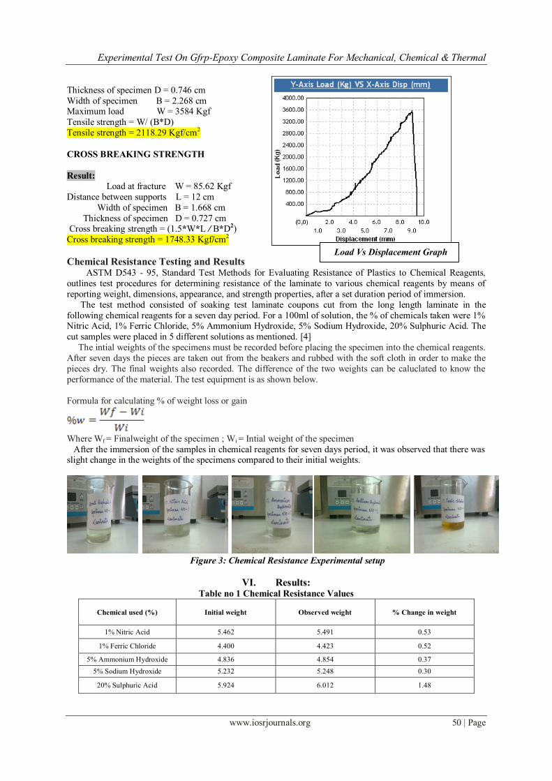
Thickness of specimen D = 0.746 cm
Width of specimen B = 2.268 cm Maximum load W = 3584 Kgf
Tensile strength = W/ (B*D)
Tensile strength = 2118.29 Kgf/cm2
CROSS BREAKING STRENGTH
Result:
Load at fracture W = 85.62 Kgf
Distance between supports L = 12 cm
Width of specimen B = 1.668 cm
Thickness of specimen D = 0.727 cm Cross breaking strength = (1.5*W*L / B*D2)
Cross breaking strength = 1748.33 Kgf/cm2
Chemical Resistance Testing and Results ASTM D543 - 95, Standard Test Methods for Evaluating Resistance of Plastics to Chemical Reagents,
outlines test procedures for determining resistance of the laminate to various chemical reagents by means of
reporting weight, dimensions, appearance, and strength properties, after a set duration period of immersion.
The test method consisted of soaking test laminate coupons cut from the long length laminate in the
following chemical reagents for a seven day period. For a 100ml of solution, the % of chemicals taken were 1% Nitric Acid, 1% Ferric Chloride, 5% Ammonium Hydroxide, 5% Sodium Hydroxide, 20% Sulphuric Acid. The
cut samples were placed in 5 different solutions as mentioned. [4]
The intial weights of the specimens must be recorded before placing the specimen into the chemical reagents.
After seven days the pieces are taken out from the beakers and rubbed with the soft cloth in order to make the
pieces dry. The final weights also recorded. The difference of the two weights can be caluclated to know the
performance of the material. The test equipment is as shown below.
Formula for calculating % of weight loss or gain
Where Wf = Finalweight of the specimen ; Wi = Intial weight of the specimen
After the immersion of the samples in chemical reagents for seven days period, it was observed that there was slight change in the weights of the specimens compared to their initial weights.
Figure 3: Chemical Resistance Experimental setup
VI. Results: Table no 1 Chemical Resistance Values
Chemical used (%)
Initial weight
Observed weight % Change in weight
1% Nitric Acid 5.462 5.491 0.53
1% Ferric Chloride 4.400 4.423 0.52
5% Ammonium Hydroxide 4.836 4.854 0.37
5% Sodium Hydroxide 5.232 5.248 0.30
20% Sulphuric Acid 5.924 6.012 1.48
Load Vs Displacement Graph

Experimental Test On Gfrp-Epoxy Composite Laminate For Mechanical, Chemical & Thermal
www.iosrjournals.org 51 | Page
Impact Testing (Charpy & Izod): The impact test is a standardized high strain rate test which determines the amount of energy absorbed
by a material during fracture. This absorbed energy is a measure of a given material‟s notch toughness and acts
as a tool to study temperature-dependant ductile-brittle transition. This test is carried out as per ASTM D 256-04
at room temperature. Dimensions of Izod impact test specimen are 12.5x7.58x65 mm where as the dimensions
for charpy-v notch test specimen is 12.5x7.58x55 mm. Depth of notch is 2.54mm and the included angle of the
notch shall be 450. [5]
Results:
Type of test Location of sample Absorbed energy(joules)
Charpy-V Longitudinal direction 14
Izod-V Longitudinal direction 12
Thermal Contact Conductance:
Thermal contact conductance is a measure of the ability of a material to transfer heat per unit time,
given one unit area of the material and a temperature gradient through the thickness of the material. It is
measured in watts per meter per degree Kelvin. Diameter of specimen = 0.25m
Area = 4.908x10⁻⁴ m2
Thickness of specimen = 7.36x10⁻³ m
Results:
Q = 17.86watts
K = Q. ∆x/A.∆T
K = 3.52 W/m K
Thermal conductivity of GFRP laminates
Specimen K = 3.52 W/m K

Experimental Test On Gfrp-Epoxy Composite Laminate For Mechanical, Chemical & Thermal
www.iosrjournals.org 52 | Page
Graphical representation on Thermal contact conductance
VII. Conclusion
In this work, GFRP laminate was prepared by hand layup process in order to evaluate mechanical,
chemical and thermal properties. This GFRP laminate composition is used in manufacturing of wind turbine
blades, cooling tower blades etc. instead of aluminium blades in order to avoid pitting on the surfaces, scales
formation and reduction of maintenance cost as well. This material possess very good insulating properties and
very less reactive to the chemicals.
Acknowledgement
Authors sincere thanks to Principal and Technical team of R&D centre, Sree Nidhi institute of Science
& Technology, Hyderabad and Managing Director of Paru Engineers Pvt ltd for extending all sort of help in
bringing out this technical paper .
References
[1] „Mechanics of composite materials‟ Madhujit Mukhopadhyay, Universities Press (India) private limited
[2] „Manufacturing process of FRP fan blades‟ by RECONDO LIMITED, MUMBAI, INDIA
[3] „Laminated plastics‟ Duffin, D.J., Reinhold publishing corporation, New York
[4] „Chemical Resistance in accordance with ASTM D543‟
[5] „ASTM D256-04 Standard Test Methods for Determining the Charpy Impact Resistance of Notched Specimens of Plastics
[6] „IS 1998-1962‟ Indian standard test method for tensile properties.
Figure 4: Thermal conductivity setup
Research & Development Centre, SNIST,
Hyderabad