Embed Size (px)
Citation preview

AD
AD-E403 213
Technical Report ARMET-TR-09004
FRICTION ON CRACK SURFACES DURING COMPRESSION OF EXPLOSIVES A SOURCE OF HOT SPOTS AND PROBABLE IGNITION SITES
Donald A. Wiegand Brett Redingius
U.S. Army ARDEC
Kevin Ellis Claire Leppard
Atomic Weapons Establishment United Kingdom
May 2009
U.S. ARMY ARMAMENT RESEARCH, DEVELOPMENT AND ENGINEERING CENTER
Munitions Engineering Technology Center
Picatinny Arsenal, New Jersey
Approved for public release; distribution is unlimited.
20090610630

The views, opinions, and/or findings contained in this report are those of the author(s) and should not be construed as an official Department of the Army posi- tion, policy, or decision, unless so designated by other documentation.
The citation in this report of the names of commercial firms or commercially available products or services does not constitute official endorsement by or approval of the U.S. Government.
Destroy this report when no longer needed by any method that will prevent disclosure of its contents or reconstruction of the document. Do not return to the originator.

REPORT DOCUMENTATION PAGE Form Approved OMBNo. 0704-01-0188
The public reporting burden for this collection of information is estimated to average 1 hour per response, including the time for reviewing instructions, searching existing data sources, gathering and maintaining the data needed, and completing and reviewing the collection of information. Send comments regarding this burden estimate or any other aspect of this collection of information, including suggestions for reducing the burden to Department of Defense, Washington Headquarters Services Directorate for Information Operations and Reports (0704-0188). 1215 Jefferson Davis Highway, Suite 1204, Arlington, VA 22202-4302. Respondents should be aware that notwithstanding any other provision of law, no person shall be subject to any penalty for failing to comply with a collection of information if it does not display a currently valid OMB control number. PLEASE DO NOT RETURN YOUR FORM TO THE ABOVE ADDRESS.
1. REPORT DATE (DD-MM-YYYY) May 2009
2. REPORT TYPE 3. DATES COVERED (From- To)
4. TITLE AND SUBTITLE
FRICTION ON CRACK SURFACES DURING COMPRESSION OF EXPLOSIVES - A SOURCE OF HOT SPOTS AND PROBABLE IGNITION SITES
5a. CONTRACT NUMBER
5b. GRANT NUMBER
5c. PROGRAM ELEMENT NUMBER
6. AUTHORS 5d. PROJECT NUMBER
Donald A. Wiegand and Brett Redingius, U.S. Army ARDEC
Kevin Ellis and Claire Leppard, Atomic Weapons Establishment, United Kingdom
5e. TASK NUMBER
5f. WORK UNIT NUMBER
7. PERFORMING ORGANIZATION NAME(S) AND ADDRESS(ES) U.S. Army ARDEC, METC Atomic Weapons Establishment Energetics, Warheads & Manufacturing Aldermaston, United Kingdom Technology Center (RDAR-MEE-W) Picatinny Arsenal, NJ 07806-5000
8. PERFORMING ORGANIZATION REPORT NUMBER
9. SPONSORING/MONITORING AGENCY NAME(S) AND ADDRESS(ES) U.S. Army ARDEC, ESIC Technical Research Center (RDAR-EIK) Picatinny Arsenal, NJ 07806-5000
10. SPONSOR/MONITOR'S ACRONYM(S)
11. SPONSOR/MONITOR'S REPORT NUMBER(S)
Technical Report ARMET-TR-09004 12. DISTRIBUTION/AVAILABILITY STATEMENT
Approved for public release; distribution is unlimited.
13. SUPPLEMENTARY NOTES
14. ABSTRACT The mechanical properties of composite plastic bonded explosives were investigated as a function of
confining pressure. The results indicate different failure processes in two pressure ranges, a low pressure range between about 0.1 to 7.0 MPa, which is considered in this paper and a higher pressure range. In the low pressure range, crack processes are important in failure. The pressure dependence of the compressive strength in the low pressure range is attributed to coulomb friction between surfaces of closed shear cracks and from the observed linear increase of the strength with pressure and the angle of the fracture plane a friction coefficient is obtained. A friction coefficient can also be obtained from the ratio of the compressive to tensile strength and directly form the above angle. The friction coefficient obtained from these three separate observations is in agreement and this is taken as strong evidence for the importance of this friction in determining strength and mechanical failure. Frictional heating during deformation can then cause hot spots leading to ignition. 15. SUBJECT TERMS
Friction, Cracks, Failure plane, Failure angle, Composite, Stress, Strain, Shear, Compression, and Pressure
16. SECURITY CLASSIFICATION OF:
a. REPORT U
b. ABSTRACT U
c. THIS PAGE U
17. LIMITATION OF ABSTRACT
SAR
18. NUMBER OF PAGES
24
19a. NAME OF RESPONSIBE PERSON Donald A. Wiegand 19b. TELEPHONE NUMBER (Include area
code) (973) 724-3336 Standard Form 298 (Rev. 8/98)
Prescribed by ANSI Std. Z39.18

ACKNOWLEDGMENT
This work was supported by Atomic Weapons Establishment, Aldermaston, United Kingdom.

CONTENTS
Page
Introduction 1
Experimental 1
Results 2
Discussion 5
Summary and Conclusions 9
References 11
Distribution List 15
in

INTRODUCTION
Explosives and propellants are often used under conditions of confinement and pressurization. Explosives are confined in projectile cases and are pressurized during launch by set-back forces and during impact by set forward forces. Propellants are confined by the breech and are pressurized by hot gases during burning. Because of these pressurizations, the properties of explosives and propellants under pressure are of interest. In particular, the mechanical properties under pressure are needed for modeling and safety considerations. For example, for the modeling of an explosive filled projectile during launch or impact, the mechanical properties of the explosive under pressure are required. Similarly, for the modeling of a propellant charge during burning, the mechanical properties of the propellant under pressure are required. Of particular concern are the mechanical failure properties under pressure. Fracture or yield during the use of explosives can lead to unwanted and/or hazardous ignitions (refs. 1 through 4). In addition, the fracture of propellants during burning can lead to hazardous burning conditions (ref. 5). The results presented here also indicate the possible hazards associated with crack processes (ref. 6). Because of these considerations, a program was initiated to study the mechanical properties of these materials under hydrostatic pressure (refs. 9 and 10).
EXPERIMENTAL
A high pressure chamber designed at Structural Behavior Engineering Laboratory, Phoenix, Arizona to contain pressures up to 138 MPa was used to study the compressive mechanical properties as a function of confining pressure (ref. 7). Hydraulic oil was used as the confining medium and the sample in the form of a right circular cylinder was protected from the oil by a tight fitting tubular gum rubber or neoprene shroud. The ends of the sample were against steel platens and O-ring seals were used to prevent oil from reaching the sample (refs. 7 through 10). The confining pressure is taken here as the chamber hydrostatic pressure before the start of and/or during the axial compression. In all cases, the pressures referred to here are this hydrostatic pressure. The chamber pressure was determined using a SENSOTEC pressure gauge, model JTE/1108-03, calibrated by the manufacturer and mounted at the base of the chamber. In addition, A McDaniel Controls dial pressure gauge was mounted at the pump. Measurements at atmospheric pressure (0.1 MPa) were made in air.
The samples were compressed along the cylindrical axis and two linear voltage differential transformers (LVDTs) were mounted to measure axial strains. They were spaced 180 deg apart around the circumference of the sample with their axes parallel to the sample axis. The sample axial strain was taken as the average of the strains obtained from the two LVDTs. Two or three additional LVDTs were mounted to measure radial strains. They were placed in a plane at the sample axial mid position with their axes perpendicular to the sample axis. They were also 180 deg apart (or 120 deg for three radial LVDTs) around the sample circumference (refs. 7 through 10).
Axial stress versus axial strain data in compression were obtained using the chamber described previously and an MTS servo-hydraulic system operated at a constant displacement rate (refs. 11 and 12). All work presented was carried out at strain rates of approximately 0.0005/sec and 0.001/sec with the exception of results explicitly a function of strain rate. The right circular cylinder samples were 3.81 cm (1.50 in.) in length and 1.90 cm (0.75 in.) in diameter and so had a length to diameter ratio of two. The end faces of all samples were coated
with a lubricant to minimize frictional effects between the sample end faces and the loading platens. The sample temperatures during measurements were between 20 and 23°C and samples were conditioned at temperature for at least 2 hrs before measurement. The dimensions of all samples at 0.1 MPa (atmospheric pressure) were used to obtain engineering stress and engineering strain.
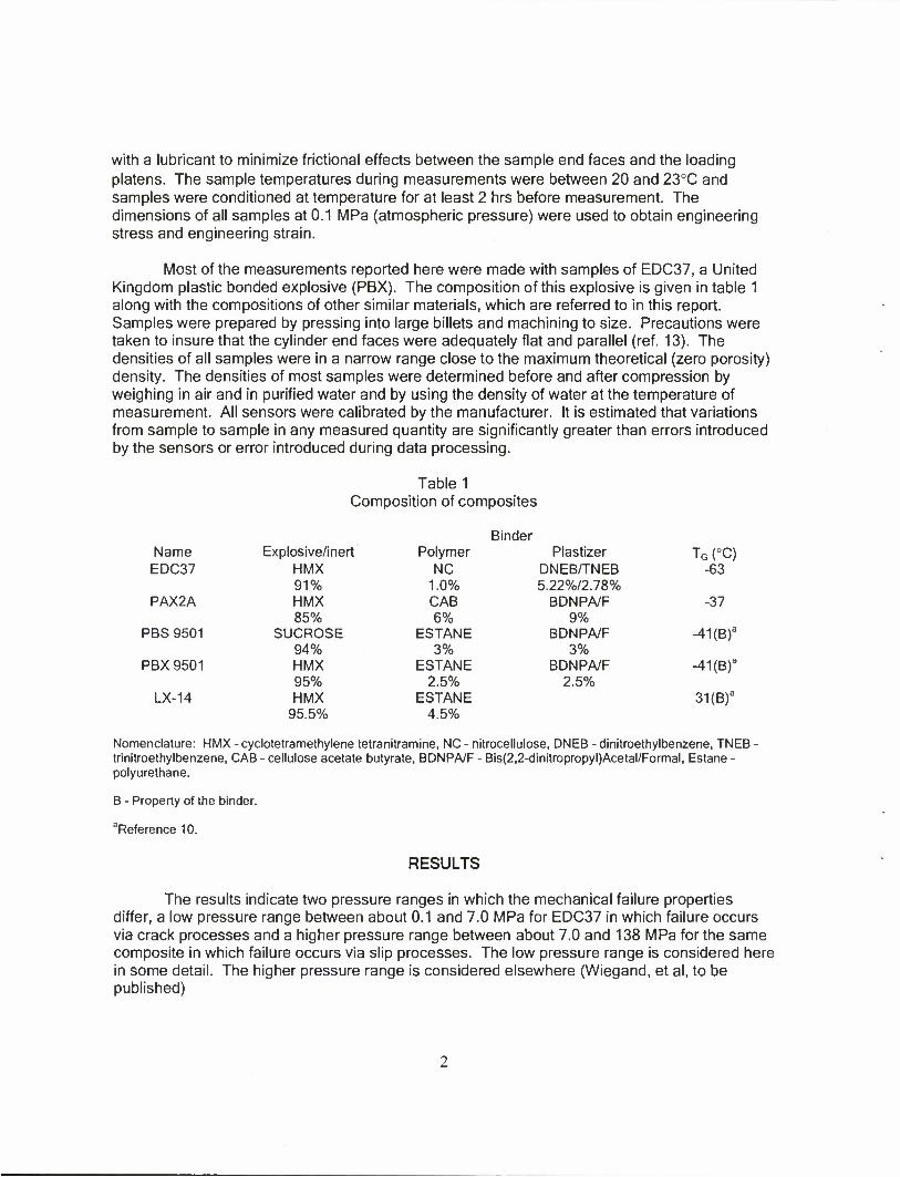
Most of the measurements reported here were made with samples of EDC37, a United Kingdom plastic bonded explosive (PBX). The composition of this explosive is given in table 1 along with the compositions of other similar materials, which are referred to in this report. Samples were prepared by pressing into large billets and machining to size. Precautions were taken to insure that the cylinder end faces were adequately flat and parallel (ref. 13). The densities of all samples were in a narrow range close to the maximum theoretical (zero porosity) density. The densities of most samples were determined before and after compression by weighing in air and in purified water and by using the density of water at the temperature of measurement. All sensors were calibrated by the manufacturer. It is estimated that variations from sample to sample in any measured quantity are significantly greater than errors introduced by the sensors or error introduced during data processing.
Table 1 Composition of composites
Binder Name Explosive/inert Polymer Plastizer TG (°C)
EDC37 HMX NC DNEB/TNEB -63 91% 1.0% 5.22%/2.78%
PAX2A HMX CAB BDNPA/F -37 85% 6% 9%
PBS 9501 SUCROSE ESTANE BDNPA/F -41(B)a
94% 3% 3% PBX 9501 HMX ESTANE BDNPA/F -41(B)a
95% 2.5% 2.5% LX-14 HMX
95.5% ESTANE
4.5% 31(B)a
Nomenclature: HMX - cyclotetramethylene tetranitramine, NC - nitrocellulose, DNEB - dinitroethylbenzene, TNEB • trinitroethylbenzene, CAB - cellulose acetate butyrate, BDNPA/F - Bis(2,2-dinitropropyl)Acetal/Formal, Estane - polyurethane.
B - Property of the binder.
Reference 10.
RESULTS
The results indicate two pressure ranges in which the mechanical failure properties differ, a low pressure range between about 0.1 and 7.0 MPa for EDC37 in which failure occurs via crack processes and a higher pressure range between about 7.0 and 138 MPa for the same composite in which failure occurs via slip processes. The low pressure range is considered here in some detail. The higher pressure range is considered elsewhere (Wiegand, et al, to be published)

In figure 1, axial stress versus axial strain curves for EDC37 are given for several confining pressures in the low pressure range. The pressures are as marked. The curve at atmospheric pressure (0.1 PMa) has the typical response of many energetic materials at this pressure and temperature (i.e., an initial linear increase of stress) a maximum stress followed by work softening (decrease of stress) with increasing strain (refs. 13 and 14). Available evidence indicates that the deviation from linearity after the initial linear region, the maximum and the work softening are associated with crack damage (refs. 15 and 16). In fact, acoustic emission results suggest that some crack damage is generated throughout the stress-strain curve (ref. 17). Evidence of surface cracking is observed for most samples deformed into the higher strain parts of the work softening region at atmospheric pressure.
M Ml « IB <M •• •«
Figure 1 Axial stress versus axial strain for pressures in the low pressure range
Both the initial slope and the maximum stress increased with pressure, while the negative work softening slope decreases with increasing pressure and is close to zero at a pressure of 6.9 MPa. The latter result suggests that either crack damage decreases with increasing pressure and is negligible at 6.9 MPA or that crack damage is generated, but that other factors prevent the work softening from being observed. The latter is apparently the case as discussed elsewhere (ref. 18). Somewhat similar results were obtained for PBS 9501 (ref. 10).
In the higher pressure range, which is about 7.0 MPa to 138 MPa for EDC37, the slope at larger strains is positive, [i.e., work hardening is observed and a maximum in the stress-strain curve is not observed (not shown)]. In this pressure range, the initial slope, which gives the modulus, the yield strength and the work hardening slope all increased with increasing pressure, but are much less sensitive to pressure than the modulus, the compressive strength and the work softening slope in the low pressure range. Somewhat similar results were obtained for PBS 9501 (ref. 10) and LX-14 (Wiegand and Reddingius, unpublished). As noted, the higher pressure range will be discussed in detail elsewhere (ref. 18).

In figure 2, the compressive strength (the maximum compressive stress) is given versus confining pressure in the low pressure range for EDC37 and a straight line has been fitted to the data points. The results indicate a linear increase with increasing pressure with a slope close to two. Similar results were obtained at other strain rates. More limited results for PBS 9501 also indicate a similar increase of the compressive strength with increasing pressure. The results of figures 1 and 2 indicate that crack processes are inhibited by confining pressure; i.e., the stress required at any strain to cause crack damage increases with increasing confining pressure.
Figure 2 Compressive strength versus pressure for pressures in the low pressure range
As noted, the yield strength for EDC37 also increases with increasing pressure in the higher pressure range (not shown). However, the slope in the higher pressure range is about 1/40 of the slope of the compressive strength versus pressure as given in figure 2 for the low pressure range.
After compression, the samples are barreled; i.e., the diameter at the sample mid plane is greater than the diameters at the sample ends. However, in all cases, there is an increase in the sample average diameter and a decrease in the average sample length due to deformation.
The dimensions and densities of all samples were measured at atmospheric pressure before and after compression. The dimensions were determined by measurements at several locations on the sample and averaged. As noted, the lengths of all samples after compression are decreased relative to values before compression so that all have permanent negative (compressive) axial strains. In addition, the average diameters of all samples after compression are increased relative to values before compression so that all have positive permanent radial strains. The volumes and densities of most samples were determined by weighing in air and in purified water and by use of the water density at the temperature of measurement. The volumes before and after compression indicate small volume expansions due to deformation. In addition, the density measurements indicate small fractional density decreases with deformation ranging from hundredths of a percent up to about 3.9%.

DISCUSSION
The results in the low pressure range can be understood on the basis of a friction model developed by Dienes (ref. 19) and Zuo and Dienes (refs. 20 and 21). Other authors have also considered the effect of friction on the mechanical properties of materials (refs. 22 through 27). Dienes (ref. 19) and Zuo and Dienes (refs. 20 and 21) have applied the concept of coulomb friction forces between closed shear crack surfaces as resisting crack motion (ref. 28). This is illustrated by the sketch in figure 3. aa is the applied compressive stress; aap is the applied
stress on a shear plane; p , whose normal makes an angle </> with the applied stress direction;
and aps and apn are the components of aap parallel and perpendicular to the shear plane,
respectively. These later stresses are given in terms of oa and <j> as
aps =<Ja C°s <t&m<t> (1)
°> = oc,Cos2(t> (2)
The net shearing stress on the plane p is then
asne< = aps ~ ^apn (3)
where // is the friction coefficient. And if a hydrostatic pressure P is applied to the sample in
addition to the applied uniaxial stress aa equation 3 becomes
V.snel=°Ps-V(<Tan+P) (4a)
= aclCos<fiSin0- f.i{aaCos2<l> + P) (4b)
by using equations 1 and 2.
Then equation 4b can be rearranged to give
aa ={crsnet + /.iP)/\Sin4Cos0-JLICOS <f>) (5)

Figure 3 Stresses for the friction model
If equation 5 is applied to the maximum of the stress-strain curve, then <ysmt is the shear stress at the maximum. Thus, aa increases linearly with P as observed (fig. 2), if <jsnet is independent of pressure or is linearly dependent on pressure. For the case of asnet, independent of pressure <ra increased linearly with pressure with a slope of
slope = n/\Sin0Cos0 - /JCOS <j>) (6)
The angle </> is determined by the plane on which the shear stress, asnel, is a maximum. By differentiating equation 4b with respect to <j> with constant aa , n , and P and setting the differential equal to zero the following is obtained
Tarr4-2fO'(m$-l = 0
And by taking the positive route
Tart(t> = n + (ju2+lf2
(7)
(8)
Thus, by measuring the angle <j>, /u can be determined from equation 8. /J can also be determined from equation 6 using the slope of figure 2 and the measured value of <j>. Note that the angle </> is independent of P. It is assumed here that the samples are isotropic and thus that all crack orientations exist.
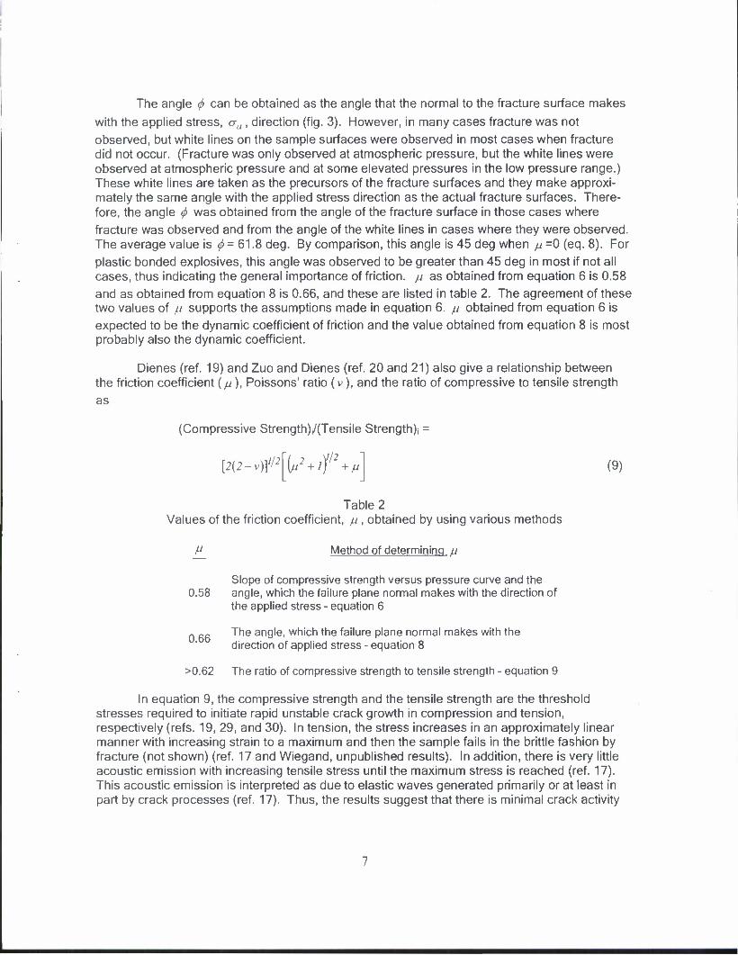
The angle <f> can be obtained as the angle that the normal to the fracture surface makes
with the applied stress, oa , direction (fig. 3). However, in many cases fracture was not
observed, but white lines on the sample surfaces were observed in most cases when fracture did not occur. (Fracture was only observed at atmospheric pressure, but the white lines were observed at atmospheric pressure and at some elevated pressures in the low pressure range.) These white lines are taken as the precursors of the fracture surfaces and they make approxi- mately the same angle with the applied stress direction as the actual fracture surfaces. There- fore, the angle <f> was obtained from the angle of the fracture surface in those cases where
fracture was observed and from the angle of the white lines in cases where they were observed. The average value is <f> = 61.8 deg. By comparison, this angle is 45 deg when n =0 (eq. 8). For
plastic bonded explosives, this angle was observed to be greater than 45 deg in most if not all cases, thus indicating the general importance of friction, /J as obtained from equation 6 is 0.58 and as obtained from equation 8 is 0.66, and these are listed in table 2. The agreement of these two values of /J supports the assumptions made in equation 6. ju obtained from equation 6 is
expected to be the dynamic coefficient of friction and the value obtained from equation 8 is most probably also the dynamic coefficient.
Dienes (ref. 19) and Zuo and Dienes (ref. 20 and 21) also give a relationship between the friction coefficient (//), Poissons' ratio (v), and the ratio of compressive to tensile strength as
(Compressive Strength)j/(Tensile Strength); =
[2(2-v)]>/2\^2 + lf2 + ^ (9)
Table 2 Values of the friction coefficient, ju, obtained by using various methods
M Method of determining u
Slope of compressive strength versus pressure curve and the 0.58 angle, which the failure plane normal makes with the direction of
the applied stress - equation 6
„ Rfi The angle, which the failure plane normal makes with the direction of applied stress - equation 8
>0.62 The ratio of compressive strength to tensile strength - equation 9
In equation 9, the compressive strength and the tensile strength are the threshold stresses required to initiate rapid unstable crack growth in compression and tension, respectively (refs. 19, 29, and 30). In tension, the stress increases in an approximately linear manner with increasing strain to a maximum and then the sample fails in the brittle fashion by fracture (not shown) (ref. 17 and Wiegand, unpublished results). In addition, there is very little acoustic emission with increasing tensile stress until the maximum stress is reached (ref. 17). This acoustic emission is interpreted as due to elastic waves generated primarily or at least in part by crack processes (ref. 17). Thus, the results suggest that there is minimal crack activity

until the maximum tensile stress is achieved and that this maximum stress is the stress necessary to initiate rapid unstable crack growth. In contrast, in compression acoustic emission was observed throughout most of the increasing stress part of the stress strain curve, through the maximum and into the work softening part of the curve (ref. 17), but fracture indicating unstable rapid crack growth was not observed. (See the stress-strain curve at atmospheric pressure in figure 1.) It is suggested that only slow crack growth (ref. 31) occurs during the compressive stress-strain curve and that the observed acoustic emission is primarily or at least in part due to this slow crack growth. It is further suggested that the damage introduced by this slow crack growth so weakens the sample that the stress required for unstable rapid crack growth in compression is not attained. Rapid unstable crack growth is observed in compression at low temperature (refs. 32 and 33). Slow crack growth is not expected at low temperatures.
Slow crack growth is thermally activated and stress assisted (ref. 31), and does not have an explicit threshold stress. In contrast, rapid unstable crack growth does have a threshold stress. Dienes (ref. 15) and Dienes and Reilly (ref. 16) used crack growth models without thresholds to obtain fits to Wiegand's (unpublished results) uniaxial compressive stress-strain data for PBX 9501. In addition, Dienes (ref. 15) was able to obtain a fit to the strain rate dependence of Wiegand's results only by introducing slow crack growth into his model. Modelers at Atomic Weapons Establishment, Aldermaston, United Kingdom have found a very low stress threshold for crack growth in EDC37 (ref. 34). All of these results support the hypothesis that primarily slow crack growth and not rapid unstable crack growth occurs in compression in these composites for the conditions of interest here. The maximum stress observed in compression, the compressive strength, is then less than the stress required for rapid unstable crack growth and this latter stress is not observed for the reason given previously. Returning then to equation 9, a calculation of the friction coefficient using the compressive strength and the tensile strength will yield a coefficient, which is less than the true value because the compressive strength is less than the stress required for rapid unstable crack growth. Poisson's ratio was found to be 0.42 for EDC37 in the low pressure range using neoprene shrouds and the system described previously in the experimental section. The ratio of compressive to tensile strengths is 3.2 for the conditions of this work (Ellis, unpublished). Then /j obtained from equation 9 is 0.62 and this is listed in table 3 as a lower limit. The agreement between two of the values of /y (table 2) as obtained from equations 6 and 8 and the minimum
value as obtained from equation 9 provide significant support for the role of friction in determining the compressive stresses. Values of // for three other composite plastic bonded explosives obtained using equation 9 are somewhat close to the values for EDC37.
It is to be noted that at high strain rates the time available for slow crack growth for a given range of strain will be much less than the time needed for the same range of strains at low strain rates. Therefore, the damage introduced by slow crack growth will be less at the higher strain rate. Thus, the sample will support larger stresses at the higher rate and so the stress may increase to that required for rapid unstable crack growth and fracture.
Because there is friction between crack surfaces associated with crack motion, there will be heating of the crack surfaces. This raises the possibility of ignition of reaction at crack surfaces because of this heating. Zuo and Dienes (refs. 20 and 21) have presented evidence of reaction at cracks surfaces taken from the work of Howe, et.al (ref. 1). These latter investigators impacted artillery shells containing TNT and afterwards polished TNT surfaces to reveal cracks. In particular, several cracks exhibited evidence of reaction along the crack length, thus giving

support to the hypothesis of ignition due to frictional heating at the crack surfaces. In addition, Dienes, et.al (ref. 35) have calculated particle velocity versus time, curves which are very similar, to observed curves of Mulford, et.al (ref. 36) for PBX 9501 subjected to multiple shocks. Dienes, et.al used a model in which frictional heating on shear cracks raises the local temperature and pressure sufficiently to initiate reaction. Both of these works indicate the very practical importance of friction between the surfaces of cracks in explosives.
SUMMARY AND CONCLUSIONS
A linear increase of the compressive strength with increasing pressure is attributed to the effect of coulomb friction between the surfaces of closed shear cracks. The slope obtained from this linear relationship is proportional to the friction coefficient and is also dependent on the failure angle, the angle which the failure plane, the plane of maximum shear stress, makes with the loading direction. In addition, Dienes (ref. 19) and Zuo and Dienes (refs. 20 and 21) predict a relationship between the friction coefficient and only the failure angle. The friction coefficient obtained from the slope of the strength versus pressure curve and the failure angle is in sub- stantial agreement with the coefficient obtained only from the failure angle. These authors also predict a relationship between the friction coefficient and the ratio of compressive strength to tensile strength, at atmospheric pressure. A lower limit on the value of the friction coefficient was obtained from this relationship, which is in agreement with the other values noted immediately. This agreement of friction coefficients obtained from the three different relation- ships is taken as strong support for the role of friction in the mechanical properties of this composite.

REFERENCES
1. Howe, P.; Gibbons, G.; and Webber, P.E.; Proceedings of the Eighth Symposium on Detonation; J.M. Short and P. Leahy, editors; NSWC MP 86-194; White Oak, Silver Springs, MD 20903-5000; p 294; 1985.
2. Frey, R.; Proceedings of the Eighth Symposium on Detonation; J.M. Short and P. Leahy, editors; NSWC MP 86-194; White Oak, Silver Springs, MD 20903-5000; p. 68; 1985.
3. Coffee, C.S.; "Hot Spot Production by Moving Dislocations in a Rapidly Deforming Explosive;" Proceedings of the Eight Symposium on Detonation; J. Short, Editor; NSWC MP 86-194; White Oak, Silver Springs, MD; p 62; 1985.
4. Heavens, S.N. and Fields, J.E.; Combustion and Flame; 18 473; 1972.
5. Nicolaides, S.; Wiegand, D.A.; and Pinto, J.; "The Mechanical Behavior of Gum Propellant Grains in interior Ballistcs;" Technical Report ARLCD-TR-82010; U.S. Army Armament and Research Command; Picatinny Arsenal, NJ; 1982.
6. Wiegand, D.A.; Reddingius, B.; Ellis, K.; and Leppard, C.L.; "The Role of Friction in the Mechanical Failure Properties of a Polymer Particulate Composite;" Session H39; American Physical Society Meeting; New Orleans, LA; March 2008.
7. Wiegand, D.A.; "Effect of Confinement on The Mechanial Response of Composite Plastic Bonded Explosives;" Technical Report ARWEC-TR-09909; U.S. Army Armament Research, Development and Engineering Center, Picatinny Arsenal, NJ; 2000.
8. Wiegand, D.A.; in Shocked Compression of Condensed Matter- 1999; M.D. Furnish, C. Chhabildas, and R.S. Hixson, editors; American Institute of Physics, Melvelle, NY; p. 675; 2000.
9. Wiegand, D.A. and Reddingius, B.; in Shocked Compression of Condensed Matter- 2003; M.D. Furnish, Y.M. Gupa, and J.W. Forbes, editors; American Institute of Physics, Melvelle, NY; p. 812; 2003.
10. Wiegand, D.A. and Reddingius, B.; J. Energetic Materials; 23 75; 2005.
11. Wiegand, D.A.; Pinto, J.; and Nicolaides, S.; J. Energetic Materials; 9 19; 1991.
12. Pinto, J.; Nicolaides, S.; and Wiegand, D. A.; "Dynamic and Quasi Static Mechanical Properties of Comp B and TNT;" Technical Report ARAED-TR-85004; U.S. Army Armament Research, Development and Engineering Center, Picatinny Arsenal, NJ; 1985.
13. Wiegand, D.A.; Proceedings of the Eleventh International Detonation Symposium; J. M. Short and J.E. Kennedy; Cochairmen, ONR 33300-5; Office of Naval Research; Arlington, VA 22217-5660; p. 744; 1998.
14. Wiegand, D.A.; Proceedings of the 3rd International Conference on Deformation and Fracture; University of Surrey, United Kingdom; p. 558; March 1985.
15. Dienes, J.K.; "Strain Softening via SCRAM;" Report LA-UR-98-3620; Los Alamos National Laboratory; 1998.
II

16. Dienes, J.K. and Riely, N; "Strain Softening of PBX 9501;" Report LA-UR-98-3804, Los Alamos National Laboratory; 1998.
17. Ellis, K.; Leppard, C; and Radesk, H.; "Mechanical Properties and Damage Evaluation of a UK PBX;" J. Material Science; 40 6241; 2005.
18. Wiegand, D.A.; Reddingius, B.; Ellis, K.; and Leppard, C.L.; "Mechanical Failure Properties of a Polymer Composite as a Function of Hydrostatic Pressure;" to be published.
19. Dienes, J.K.; "On the Stability of Shear Cracks and the Calculation of Compressive Strength;" J. Geophysical Research 88; pp 1173-1179; 1983.
20. Zuo, Q.H. and Dienes, J.K.; "On Types of Brittle Fracture;" Report LA-13962-MS; Los Alamos National Laboratory; 2002.
21. Zuo, Q.H. and Dienes, J.K.; "On the Stability of Penny-Shaped Cracks with Friction: The Five Types of Brittle Failure;" International Journal of Solids and Structure; 42 1309; 2005.
22. McClintock, F.A. and Walsh, J.B.; U.S. National Congress Applied Mechanics; 4th; p. 1015; 1962.
23. Mayko, G.M.; "Frictional Attenuation: An Inherent Amplitude Dependence;" J. Physics Research; 84 4769; 1979.
24. Comninou, M. and Dundurs, J.; "Effect of Friction on the Interface Crack;" J. Elasticity; 10 203; 1980.
25. Tian-Hu, H. and Weishen, Z.; "Collinear Periodic Cracks in Anisotropic Viscoelastic Plane with Surface Separation and Friction Sliding;" Engineering Fracture Mechanics; 44 217; 1993.
26. Egami, N. and Kitaoka; "Evaluation of KM Using a Copper Foil when Assessing Frictional Forces on Crack Surfaces;" Fatigue Fract. Engng. Matrer. Struct.; 19 451; 1996.
27. Kovtunenko, V.A.; "Solid with a Crack and a Friction;" Fifth International Symposium on Methods and Models in Automation and Robotics; Miedzyzdroje, Poland; pp 25-29; August 1998.
28. Ward, I.M. and Hadley, D.W.; An Introduction to Properties of Solid Polymers; John Wiley and Sons, New York, NY; p. 223; 1993.
29. Rice, J.R.; "Comments on the Stability of Shear Cracks and the Calculation of Compressive Strength" by J.K. Dienes; J. Geophysical Research 89 2505; 1984.
30. Dienes, J.K.; Reply (to Rice; J.R.); Geophysical Research; 89 2508; 1984.
31. Charles, R.J.; Static Fatigue of Glass, II; Journal of Applied Physics, 29, 1652; 1958.
12

32. Williamson, D.M.; Palmer, S.P.J.; Proud, W.G.; and Govier, R.; "Brazilian Disc Test of a UK PBX Above and Below the Glass Transition Temperature;" American Institute of Physics Conference Proceedings in Shock Compressions of Condensed Matter, 2007; M.D. Furnish, et al, Editors.
33. Wiegand, D.A.; Proceedings 21st Army Science Conference; Norfolk, VA; p. 81; June 1999.
34. Kalsi, G.S.; Asghar, M.A.; Kernthaler, H.C.; and Lyons, L.P.R.; "A Model for Simulating the Structural Response of Polymer Bonded Materials Exhibiting Unequal Properties in Tension and Compression;" International Journal of Computers and Structures; in press.
35. Dienes, J.K.; Zuo, Q.H.; and Kershner, J.D.; Journal of Mechanics and Physical Solids; 54, 1237; 2006.
36. Mulford, R.N.; Sheffield, S.A.; and Alcon, R.A.; Proceedings of the 10th International Detonation Symposium, p. 459; 1993.
13

DISTRIBUTION LIST
U.S. Army ARDEC ATTN: RDAR-EIK
RDAR-GC RDAR-MEE-W, D. Wiegand (10)
S. Swaszek W. Davis A. Dawson D. Pfau C. Hu S. Nicolich E. Baker
RDAR-MEM-L, L. Manole RDAR-QES-B, E. Bixon
Picatinny Arsenal, NJ 07806-5000
Defense Technical Information Center (DTIC) ATTN: Accessions Division 8725 John J. Kingman Road, Ste 0944 Fort Belvoir, VA 22060-6218
Commander Soldier and Biological/Chemical Command ATTN: AMSSB-CII, Library Aberdeen Proving Ground, MD 21010-5423
Director U.S. Army Research Laboratory ATTN: AMSRL-CI-LP, Technical Library
AMXBR-BLC, J. Starkenberg P. Baker
AMXBR-TBT, R. Lieb G. Gazonas
Bldg. 4600 Aberdeen Proving Ground, MD 21005-5066
Chief Benet Weapons Laboratory, WSEC U.S. Army Research, Development and Engineering Command Armament Research, Development and Engineering Center ATTN: RDAR-WSB Watervliet, NY 12189-5000
Director U.S. Army TRADOC Analysis Center-WSMR ATTN: ATRC-WSS-R White Sands Missile Range, NM 88002
15

Chemical Propulsion Information Agency ATTN: Accessions 10630 Little Patuxent Parkway, Suite 202 Columbia, MD 21044-3204
GIDEP Operations Center P.O. Box 8000 Corona, CA 91718-8000
Office of the Secretary of Defense OUSDA(A) Director, Live Fire Testing Washington, DC 20301-3110
Director U.S. Army Aviation Research and Technology Activity Ames Research Center Moffett Field, CA 94035-1099
Commander U.S. Army Missile Command ATTN: AMSMI-RD-CS-R (DOC) Redstone Arsenal, AL 35898-5010
HQDA (SARD-TR) Washington, DC 20310-0001
Commander U.S. Army Materiel Command ATTN: AMCDRA-ST 5001 Eisenhower Avenue Alexandria, VA 22333-0001
Commander U.S. Army Laboratory Command ATTN: AMSLC-DL Adelphi, MD 20873-1145
Commandant U.S. Army Infantry School ATTN: ATSH-CD-CSO-OR Fort Benning, GA 31905-5660
Commander U.S. Army Aviation Systems Command ATTN: AMSAV-DACL 4300 Goodfellow Blvd St. Louis, MO 63120-1798
16

Commander U.S. Army Research Office ATTN: Chemistry Division P.O. Box 12211 Research Triangle Park, NC 27709-2211
Commander Naval Weapons Center ATTN: A. Amster
R. Reed, Jr. China Lake, CA 93555
Commander Ballistic Missile Defense Advanced Technology Center ATTN: D. Sayles P.O. Box 1500 Huntsville, AL 35807
Air Force Armament Technology Laboratory ATTN: AFATLVDOIL
AFATL/DLODL Eglin Air Force Base, FL 32542-5438
Southwest Research Institute ATTN: M. Cowperthwaite
H.J. Gryting 6200 Culera Road Postal Drawer 28510 San Antonio, TX 78284
New Mexico Institute of Mining and Technology ATTN: TERA, T. Joyner Campus Station Socorro, NM 87801
Director Lawrence Livermore National Laboratory ATTN: K. Scribner
J. Forbes L-324
P.O. Box 808 Livermore, CA 94550
17

Director Los Alamos National Laboratory ATTN: J960, J. Ramsay
MS B214, J. Dienes MSJ567, D.J. Funk MS C920, D. Idar
B. Asay R. Gray Q. Zuo
P.O. Box 1663 Los Alamos, NM 87115
Honeywell, Inc. ATTN: R. Tompkins 10400 Yellow Circle Drive MN 38-330 Minnetonka, MN 55343
Commander U.S. Army Armament Munition and Chemical Command ATTN: AMSMC-IRD, G.H. Cowan Rock Island, IL 61299-6000
Director Sandia National Laboratory ATTN: MS 432, J. Aidun
MS 347, R. Thomas MS 477, T.Chen
Box 5800 Albuquerque, NM
Chemical Propulsion Information Agency ATTN: Accessions 10630 Little Patuxent Parkway, Suite 202 Columbia, MD 21044-3204
Morton Thiokol, Inc. Louisiana Division ATTN: L. C. Estabrook P.O. Box 30058 Shreveport, LA 71130
Commander Naval Weapons Station ATTN: Code50-NEDED Yorktown, VA 32491
IS