Embed Size (px)
Citation preview
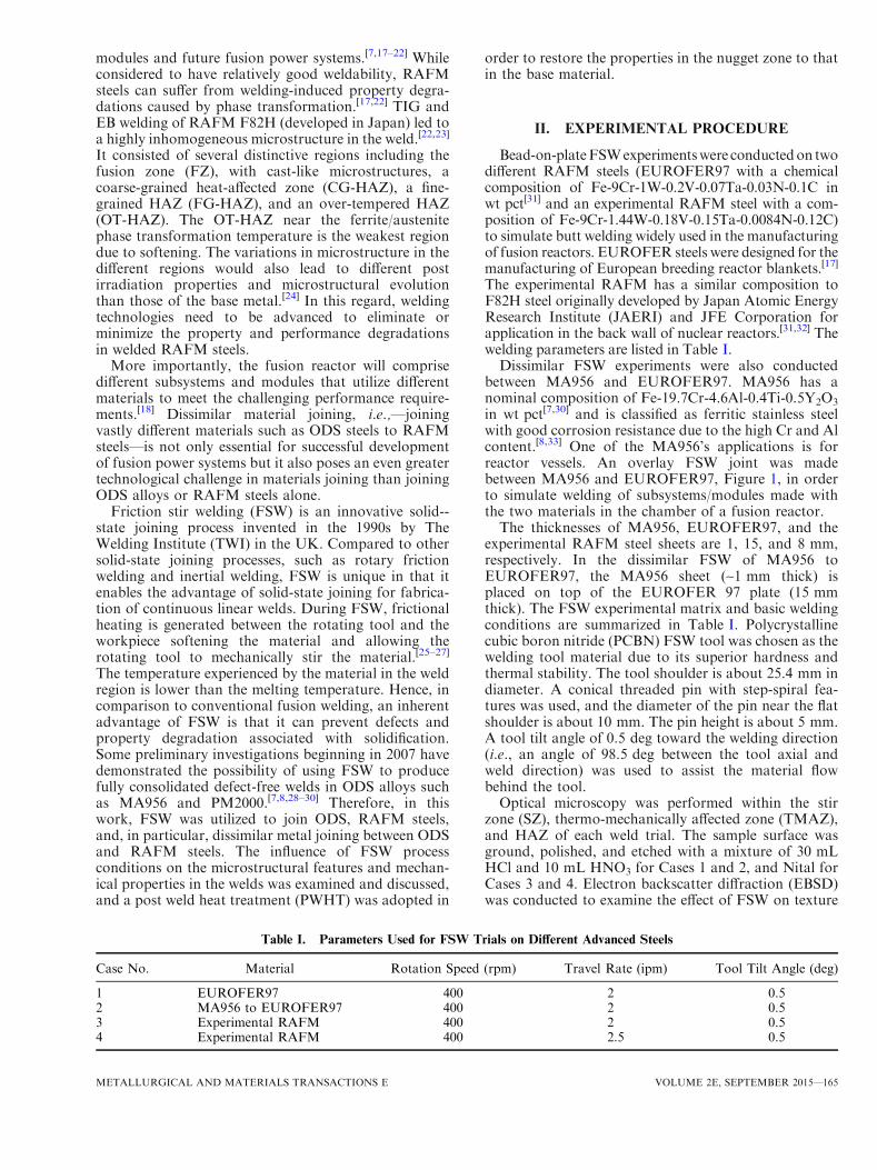
Friction Stir Welding of ODS and RAFM Steels
ZHENZHEN YU, ZHILI FENG, DAVID HOELZER, LIZHEN TAN,and MIKHAIL A. SOKOLOV
Advanced structural materials such as oxide dispersion strengthened steels andreduced-activation ferritic/martensitic steels are desired in fusion reactors as primarycandidate materials for first wall and blanket structures, due to their excellent radiation andhigh-temperature creep resistance. However, their poor fusion weldability has been the majortechnical challenge limiting practical applications. For this reason, solid-state friction stirwelding (FSW) has been considered for such applications. In this work, the effect of FSWparameters on joining similar and dissimilar advanced structural steels was investigated.Scanning electron microscopy and electron backscatter diffraction methods were used to revealthe effects of FSW on grain size, micro-texture distribution, and phase stability. Hardnessmapping was performed to evaluate mechanical properties. Post weld heat treatment was alsoperformed to tailor the microstructure in the welds in order to match the weld zone mechanicalproperties to the base material.
DOI: 10.1007/s40553-015-0054-9� ASM International (ASM) and The Minerals, Metals & Materials Society (TMS) 2015
I. INTRODUCTION
THE future fusion reactors will require utilization ofadvanced structural materials that must safely sustain theextremely hostile environment, e.g., intense heat fluxes,significant cyclic thermomechanical stresses, intensefluxes of high-energy neutrons and electromagnetic radi-ation, and reactive chemicals. These structural materialstypically feature highly complex and unique microstruc-tures tailored for high-performance properties.
For example, oxide dispersion strengthened (ODS) steelsare likely near-term candidates as fusion structural materi-als, which exhibit remarkable radiation damage resistanceand high-temperature tensile, creep, and fatiguestrengths.[1–7] The outstanding performance characteristicsof these alloys (e.g., MA956 and 12/14YWT) are attributedto the presence of an ultrahigh density of Y-Al/Ti-O richoxide particles produced through carefully engineered and
sophisticated mechanical alloying (MA) routes.[7] TakeIncoloyAlloyMA956 for example. It is an iron-basedODSferritic stainless steel with a high level of aluminum forimproved corrosion and oxidation resistance. The uniformdistribution of fine yttrium oxide dispersion particlescontributes to its excellent mechanical strength at elevatedtemperatures, and yttrium oxide particles are mostlyattached to the larger aluminum oxides.[8] ODS alloys mustbe welded for construction of fusion reactors and otherlarge-scale industry systems. However, these high-perfor-mance steels are very difficult, if not impossible, toweldwithfusion welding processes such as arc welding, laser welding,and electron beam welding. Bulk melting during fusionwelding inevitably destroys the nano-scaled particle distri-bution by causing the particles to be rejected and aggregatedat the solidification front in weld pool. The poor fusionweldability has been the major technical bottleneck limitingthe application of the entire family ofODSalloy. Solid-statewelding techniques, such as rotary friction welding,[9–11]
diffusion welding,[12] pulsed electric current sintering bond-ing,[13] brazing,[14,15] and resistance welding,[16] were evalu-ated on ODS alloys with limited success. However, thesewelding techniques have their respective drawbacks rangingfrom restricted applicable workpiece size to low jointstrength. For instance, rotary friction welding, one of themost promising techniques for joining the ODS alloys, islimited to welding small, cylindrical parts and cannot beemployed for large diameter tubing, let alone various formsof linearplate joints,whichare common joint configurationsin many high-temperature structures. Hence, new weldingtechnologies must be developed to preserve the oxidedispersion strengthening mechanism in the weld.Reduced-activation ferritic/martensitic (RAFM) steels
containing no elements with high absorption rates ofneutrons are considered as the reference first wall andblanket structural material for both International Ther-monuclear Experimental Reactor (ITER) test blanket
ZHENZHEN YU, Assistant Professor, formerly with the MaterialsScience and Technology Division, Oak Ridge National Laboratory,Oak Ridge, TN 37831, is now with the Department of Metallurgicaland Materials Engineering, Colorado School of Mines, Golden, CO80401. ZHILI FENG, Distinguished Ramp;&D Staff and GroupLeader of Materials Processing and Joining, and DAVID HOELZER,LIZHEN TAN, and MIKHAIL A. SOKOLOV, Senior R&D Staffs,are with the Materials Science and Technology Division, Oak RidgeNational Laboratory. Contact e-mail: [email protected]
This manuscript has been authored by UT-Battelle, LLC underContract No. DE-AC05-00OR22725 with the U.S. Department ofEnergy. The United States Government retains, and the publisher, byaccepting the article for publication, acknowledges, that the UnitedStates Government retains a non-exclusive, paid-up, irrevocable,world-wide license to publish or reproduce the published form of thismanuscript, or allow others to do so, for United States Governmentpurposes. The U.S. Department of Energy will provide public access tothese results of federally sponsored research in accordancewith theDOEPublic Access Plan (http://energy.gov/downloads/doe-public-access-plan).
Manuscript submitted January 1, 2015.Article published online September 14, 2015
164—VOLUME 2E, SEPTEMBER 2015 METALLURGICAL AND MATERIALS TRANSACTIONS E
modules and future fusion power systems.[7,17–22] Whileconsidered to have relatively good weldability, RAFMsteels can suffer from welding-induced property degra-dations caused by phase transformation.[17,22] TIG andEB welding of RAFM F82H (developed in Japan) led toa highly inhomogeneous microstructure in the weld.[22,23]
It consisted of several distinctive regions including thefusion zone (FZ), with cast-like microstructures, acoarse-grained heat-affected zone (CG-HAZ), a fine-grained HAZ (FG-HAZ), and an over-tempered HAZ(OT-HAZ). The OT-HAZ near the ferrite/austenitephase transformation temperature is the weakest regiondue to softening. The variations in microstructure in thedifferent regions would also lead to different postirradiation properties and microstructural evolutionthan those of the base metal.[24] In this regard, weldingtechnologies need to be advanced to eliminate orminimize the property and performance degradationsin welded RAFM steels.
More importantly, the fusion reactor will comprisedifferent subsystems and modules that utilize differentmaterials to meet the challenging performance require-ments.[18] Dissimilar material joining, i.e.,—joiningvastly different materials such as ODS steels to RAFMsteels—is not only essential for successful developmentof fusion power systems but it also poses an even greatertechnological challenge in materials joining than joiningODS alloys or RAFM steels alone.
Friction stir welding (FSW) is an innovative solid--state joining process invented in the 1990s by TheWelding Institute (TWI) in the UK. Compared to othersolid-state joining processes, such as rotary frictionwelding and inertial welding, FSW is unique in that itenables the advantage of solid-state joining for fabrica-tion of continuous linear welds. During FSW, frictionalheating is generated between the rotating tool and theworkpiece softening the material and allowing therotating tool to mechanically stir the material.[25–27]
The temperature experienced by the material in the weldregion is lower than the melting temperature. Hence, incomparison to conventional fusion welding, an inherentadvantage of FSW is that it can prevent defects andproperty degradation associated with solidification.Some preliminary investigations beginning in 2007 havedemonstrated the possibility of using FSW to producefully consolidated defect-free welds in ODS alloys suchas MA956 and PM2000.[7,8,28–30] Therefore, in thiswork, FSW was utilized to join ODS, RAFM steels,and, in particular, dissimilar metal joining between ODSand RAFM steels. The influence of FSW processconditions on the microstructural features and mechan-ical properties in the welds was examined and discussed,and a post weld heat treatment (PWHT) was adopted in
order to restore the properties in the nugget zone to thatin the base material.
II. EXPERIMENTAL PROCEDURE
Bead-on-plateFSWexperimentswere conductedon twodifferent RAFM steels (EUROFER97 with a chemicalcomposition of Fe-9Cr-1W-0.2V-0.07Ta-0.03N-0.1C inwt pct[31] and an experimental RAFM steel with a com-position of Fe-9Cr-1.44W-0.18V-0.15Ta-0.0084N-0.12C)to simulate butt welding widely used in the manufacturingof fusion reactors. EUROFER steels were designed for themanufacturing of European breeding reactor blankets.[17]
The experimental RAFM has a similar composition toF82H steel originally developed by Japan Atomic EnergyResearch Institute (JAERI) and JFE Corporation forapplication in the back wall of nuclear reactors.[31,32] Thewelding parameters are listed in Table I.Dissimilar FSW experiments were also conducted
between MA956 and EUROFER97. MA956 has anominal composition of Fe-19.7Cr-4.6Al-0.4Ti-0.5Y2O3
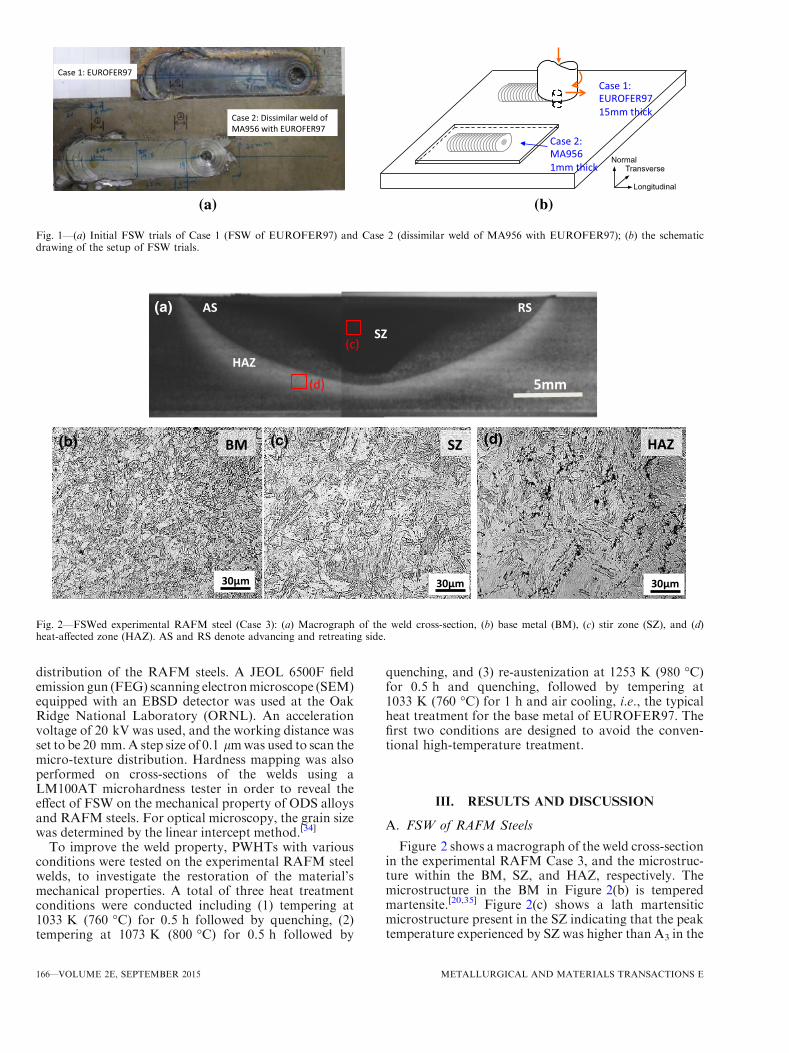
in wt pct[7,30] and is classified as ferritic stainless steelwith good corrosion resistance due to the high Cr and Alcontent.[8,33] One of the MA956’s applications is forreactor vessels. An overlay FSW joint was madebetween MA956 and EUROFER97, Figure 1, in orderto simulate welding of subsystems/modules made withthe two materials in the chamber of a fusion reactor.The thicknesses of MA956, EUROFER97, and the
experimental RAFM steel sheets are 1, 15, and 8 mm,respectively. In the dissimilar FSW of MA956 toEUROFER97, the MA956 sheet (~1 mm thick) isplaced on top of the EUROFER 97 plate (15 mmthick). The FSW experimental matrix and basic weldingconditions are summarized in Table I. Polycrystallinecubic boron nitride (PCBN) FSW tool was chosen as thewelding tool material due to its superior hardness andthermal stability. The tool shoulder is about 25.4 mm indiameter. A conical threaded pin with step-spiral fea-tures was used, and the diameter of the pin near the flatshoulder is about 10 mm. The pin height is about 5 mm.A tool tilt angle of 0.5 deg toward the welding direction(i.e., an angle of 98.5 deg between the tool axial andweld direction) was used to assist the material flowbehind the tool.Optical microscopy was performed within the stir
zone (SZ), thermo-mechanically affected zone (TMAZ),and HAZ of each weld trial. The sample surface wasground, polished, and etched with a mixture of 30 mLHCl and 10 mL HNO3 for Cases 1 and 2, and Nital forCases 3 and 4. Electron backscatter diffraction (EBSD)was conducted to examine the effect of FSW on texture
Table I. Parameters Used for FSW Trials on Different Advanced Steels
Case No. Material Rotation Speed (rpm) Travel Rate (ipm) Tool Tilt Angle (deg)
1 EUROFER97 400 2 0.52 MA956 to EUROFER97 400 2 0.53 Experimental RAFM 400 2 0.54 Experimental RAFM 400 2.5 0.5
METALLURGICAL AND MATERIALS TRANSACTIONS E VOLUME 2E, SEPTEMBER 2015—165
distribution of the RAFM steels. A JEOL 6500F fieldemission gun (FEG) scanning electronmicroscope (SEM)equipped with an EBSD detector was used at the OakRidge National Laboratory (ORNL). An accelerationvoltage of 20 kV was used, and the working distance wasset to be 20 mm.A step size of 0.1 lmwas used to scan themicro-texture distribution. Hardness mapping was alsoperformed on cross-sections of the welds using aLM100AT microhardness tester in order to reveal theeffect of FSW on the mechanical property of ODS alloysand RAFM steels. For optical microscopy, the grain sizewas determined by the linear intercept method.[34]
To improve the weld property, PWHTs with variousconditions were tested on the experimental RAFM steelwelds, to investigate the restoration of the material’smechanical properties. A total of three heat treatmentconditions were conducted including (1) tempering at1033 K (760 �C) for 0.5 h followed by quenching, (2)tempering at 1073 K (800 �C) for 0.5 h followed by
quenching, and (3) re-austenization at 1253 K (980 �C)for 0.5 h and quenching, followed by tempering at1033 K (760 �C) for 1 h and air cooling, i.e., the typicalheat treatment for the base metal of EUROFER97. Thefirst two conditions are designed to avoid the conven-tional high-temperature treatment.
III. RESULTS AND DISCUSSION
A. FSW of RAFM Steels
Figure 2 shows a macrograph of the weld cross-sectionin the experimental RAFM Case 3, and the microstruc-ture within the BM, SZ, and HAZ, respectively. Themicrostructure in the BM in Figure 2(b) is temperedmartensite.[20,35] Figure 2(c) shows a lath martensiticmicrostructure present in the SZ indicating that the peaktemperature experienced by SZ was higher than A3 in the
BM
5mm
SZ
HAZ
AS RS(a)
(b)
30μm 30μm 30μm
SZ HAZ(c) (d)
(d)
(c)
Fig. 2—FSWed experimental RAFM steel (Case 3): (a) Macrograph of the weld cross-section, (b) base metal (BM), (c) stir zone (SZ), and (d)heat-affected zone (HAZ). AS and RS denote advancing and retreating side.
(b)(a)
Case 1: EUROFER97
Case 2: Dissimilar weld ofMA956 with EUROFER97
Normal Transverse
Longitudinal
Case 1:EUROFER9715mm thick
Case 2:MA9561mm thick
Fig. 1—(a) Initial FSW trials of Case 1 (FSW of EUROFER97) and Case 2 (dissimilar weld of MA956 with EUROFER97); (b) the schematicdrawing of the setup of FSW trials.
166—VOLUME 2E, SEPTEMBER 2015 METALLURGICAL AND MATERIALS TRANSACTIONS E
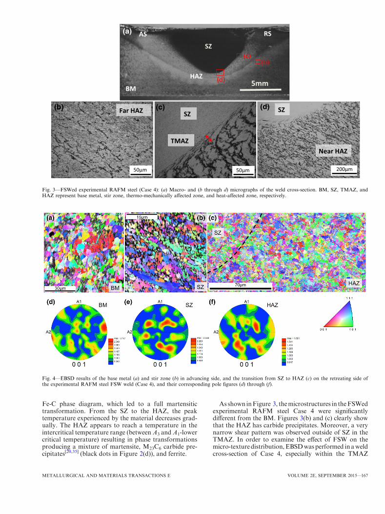
Fe-C phase diagram, which led to a full martensitictransformation. From the SZ to the HAZ, the peaktemperature experienced by the material decreases grad-ually. The HAZ appears to reach a temperature in theintercritical temperature range (betweenA3 andA1-lowercritical temperature) resulting in phase transformationsproducing a mixture of martensite, M23C6 carbide pre-cipitates[20,35] (black dots in Figure 2(d)), and ferrite.
As shown inFigure 3, themicrostructures in theFSWedexperimental RAFM steel Case 4 were significantlydifferent from the BM. Figures 3(b) and (c) clearly showthat the HAZ has carbide precipitates. Moreover, a verynarrow shear pattern was observed outside of SZ in theTMAZ. In order to examine the effect of FSW on themicro-texturedistribution,EBSDwasperformed in aweldcross-section of Case 4, especially within the TMAZ
Far HAZ(b)
50μm
(d) SZ
Near HAZ
200μm
5mm
(a)
SZ
BM
(c)(b)
(d)
SZ
TMAZ
(c)
50μm
AS RS
HAZ
Fig. 3—FSWed experimental RAFM steel (Case 4): (a) Macro- and (b through d) micrographs of the weld cross-section. BM, SZ, TMAZ, andHAZ represent base metal, stir zone, thermo-mechanically affected zone, and heat-affected zone, respectively.
Fig. 4—EBSD results of the base metal (a) and stir zone (b) in advancing side, and the transition from SZ to HAZ (c) on the retreating side ofthe experimental RAFM steel FSW weld (Case 4), and their corresponding pole figures (d) through (f).
METALLURGICAL AND MATERIALS TRANSACTIONS E VOLUME 2E, SEPTEMBER 2015—167
region. Figure 4(a) shows that the base metal has anaveraged grain size of ~4 lm. The high-angle grainboundaries are defined as thosewithmisorientation angleslarger than 15 deg. As observed in Figures 4(e) through(f), there was no strong texture present in the BM, HAZ,and SZ. In other words, no significant change in themicro-texture distribution between the BM and weldregion was observed. Therefore, texture will not play anyrole in the hardness variation as observed in Figure 5. Noaustenite phase was observed in the weld.
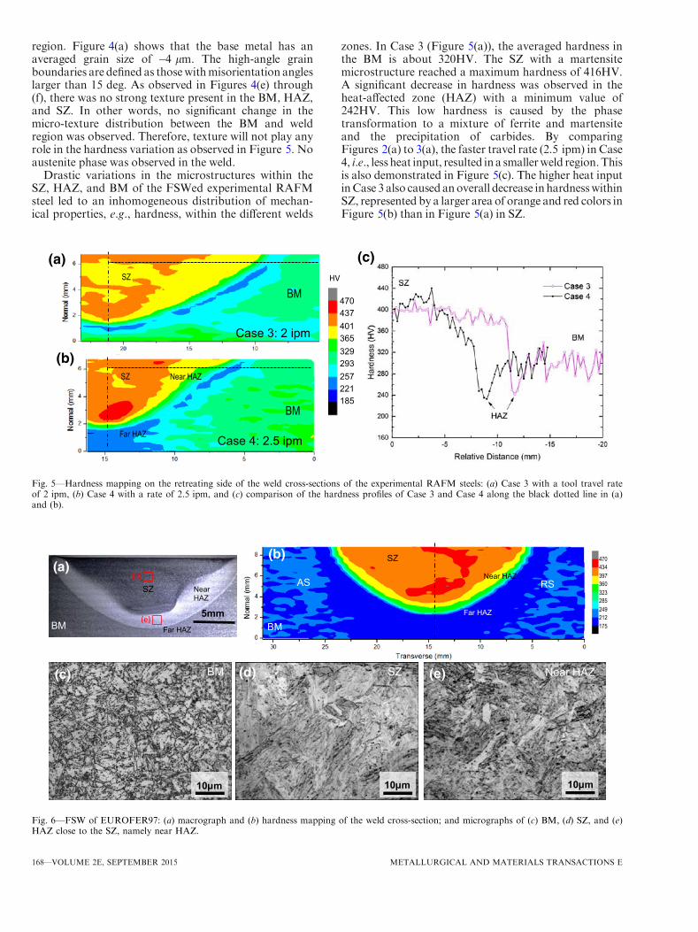
Drastic variations in the microstructures within theSZ, HAZ, and BM of the FSWed experimental RAFMsteel led to an inhomogeneous distribution of mechan-ical properties, e.g., hardness, within the different welds
zones. In Case 3 (Figure 5(a)), the averaged hardness inthe BM is about 320HV. The SZ with a martensitemicrostructure reached a maximum hardness of 416HV.A significant decrease in hardness was observed in theheat-affected zone (HAZ) with a minimum value of242HV. This low hardness is caused by the phasetransformation to a mixture of ferrite and martensiteand the precipitation of carbides. By comparingFigures 2(a) to 3(a), the faster travel rate (2.5 ipm) in Case4, i.e., less heat input, resulted in a smallerweld region.Thisis also demonstrated in Figure 5(c). The higher heat inputinCase 3 also causedanoverall decrease in hardnesswithinSZ, represented by a larger area of orange and red colors inFigure 5(b) than in Figure 5(a) in SZ.
5mm
SZ Near HAZ
BM
(a)
Far HAZ
10µm
BM SZ
10µm 10µm
Near HAZ (c) (d) (e)
(d)
(e)
SZ
Near HAZ
BM
(b)
AS RS
Far HAZ
470 434 397 360 323 285 249 212 175
Fig. 6—FSW of EUROFER97: (a) macrograph and (b) hardness mapping of the weld cross-section; and micrographs of (c) BM, (d) SZ, and (e)HAZ close to the SZ, namely near HAZ.
Case 4: 2.5 ipm
Near HAZ
Far HAZ
BM
SZ
(b)
470 437 401 365 329 293 257 221 185
HV
Case 3: 2 ipm
BM SZ
(a) (c)
Fig. 5—Hardness mapping on the retreating side of the weld cross-sections of the experimental RAFM steels: (a) Case 3 with a tool travel rateof 2 ipm, (b) Case 4 with a rate of 2.5 ipm, and (c) comparison of the hardness profiles of Case 3 and Case 4 along the black dotted line in (a)and (b).
168—VOLUME 2E, SEPTEMBER 2015 METALLURGICAL AND MATERIALS TRANSACTIONS E
As shown in Figure 6(c), the initial microstructure ofEUROFER97 is tempered martensite. The average grainsize is about 10 lm. The EUROFER97 base metalaverage hardness is ~220 HV. Figure 6(d) shows a lathmartensitic microstructure present in the SZ with coars-ened grains. The martensitic microstructure results in anearly twofold increase in hardness of the SZ, as shown inFigure 6(b). The near HAZ region is more likely in theintercritical temperature range, leading to a mixture offerrite and martensite. The dark dots in Figure 6(e)indicate the formation of carbide precipitates. Hence, alower hardness was observed in the near HAZ comparedto the SZ. The far HAZ region may have experiencedtemperature below A1, which is over tempering. Thedecreasing peak temperature experienced by the differentzones determines the gradual reduction in hardness inboth the SZandHAZ. Since high hardnesswoulddegradetoughness and creep resistance of the weld structure,PWHT is needed to restore properties of basematerial.[17]
B. Post Weld Heat Treatment
The microscopy examination showed that theas-welded microstructure in Case 3 (the experimentalRAFM steel) has significant variation in hardness,which is not optimum for high-temperature service ofthis alloy. Unlike fusion welding where filler metals areused, FSW does not change the chemistry of the weldnugget. Therefore, PWHT can potentially restore thehardness of the base material.
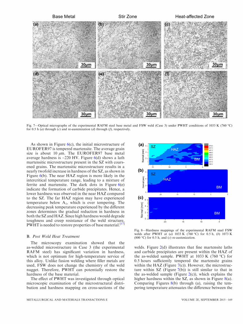
The effect of PWHT was investigated through opticalmicroscopic examination of the microstructural distri-bution and hardness mapping on cross-sections of the
welds. Figure 2(d) illustrates that fine martensite lathsand carbide precipitates are present within the HAZ ofthe as-welded sample. PWHT at 1033 K (760 �C) for0.5 hours sufficiently tempered the martensite grainswithin the HAZ (Figure 7(c)). However, the microstruc-ture within SZ (Figure 7(b)) is still similar to that inthe as-welded sample (Figure 2(c)), which explains thehigher hardness within the SZ, as shown in Figure 8(a).Comparing Figures 8(b) through (a), raising the tem-pering temperature attenuates the difference between the
Fig. 7—Optical micrographs of the experimental RAFM steel base metal and FSW weld (Case 3) under PWHT conditions of 1033 K (760 �C)for 0.5 h (a) through (c) and re-austenization (d) through (f), respectively.
(a)
(b)
(c)
BM
BM
BM
SZHAZ
SZHAZ
Fig. 8—Hardness mappings of the experimental RAFM steel FSWwelds after PWHT at (a) 1033 K (760 �C) for 0.5 h, (b) 1073 K(800 �C) for 0.5 h, and (c) re-austenization.
METALLURGICAL AND MATERIALS TRANSACTIONS E VOLUME 2E, SEPTEMBER 2015—169
hardness within SZ and BM. Figures 7(d) through (f),with a complete re-austenization process, produceduniform microstructure within the weld zones, which isidentical to the base metal microstructure (Figure 7(a)).Consequently, a homogeneous hardness distribution inthe weld was achieved in Case 3 (Figure 8(c)), in otherwords, the mechanical properties in the welded regionare comparable to the base material.
C. Dissimilar FSW of ODS and RAFM Steels
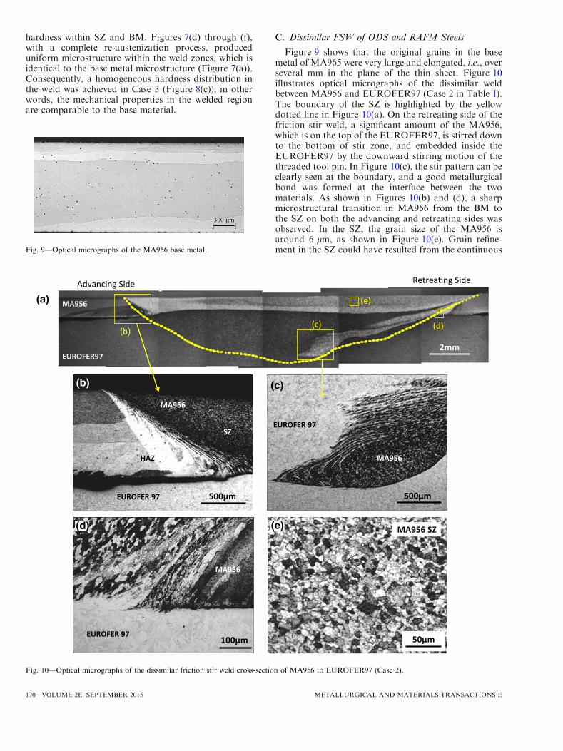
Figure 9 shows that the original grains in the basemetal of MA965 were very large and elongated, i.e., overseveral mm in the plane of the thin sheet. Figure 10illustrates optical micrographs of the dissimilar weldbetween MA956 and EUROFER97 (Case 2 in Table I).The boundary of the SZ is highlighted by the yellowdotted line in Figure 10(a). On the retreating side of thefriction stir weld, a significant amount of the MA956,which is on the top of the EUROFER97, is stirred downto the bottom of stir zone, and embedded inside theEUROFER97 by the downward stirring motion of thethreaded tool pin. In Figure 10(c), the stir pattern can beclearly seen at the boundary, and a good metallurgicalbond was formed at the interface between the twomaterials. As shown in Figures 10(b) and (d), a sharpmicrostructural transition in MA956 from the BM tothe SZ on both the advancing and retreating sides wasobserved. In the SZ, the grain size of the MA956 isaround 6 lm, as shown in Figure 10(e). Grain refine-ment in the SZ could have resulted from the continuous
500μm
(b)
500μm
(c)
(e)
MA956
EUROFER97
Advancing Side Retrea ng Side
2mm
(a)
(b)(c) (d)
(e)
100μm
MA956
HAZ
EUROFER 97
SZ
MA956
EUROFER 97
EUROFER 97
MA956
50μm
(e) MA956 SZ(d)
Fig. 10—Optical micrographs of the dissimilar friction stir weld cross-section of MA956 to EUROFER97 (Case 2).
Fig. 9—Optical micrographs of the MA956 base metal.
170—VOLUME 2E, SEPTEMBER 2015 METALLURGICAL AND MATERIALS TRANSACTIONS E
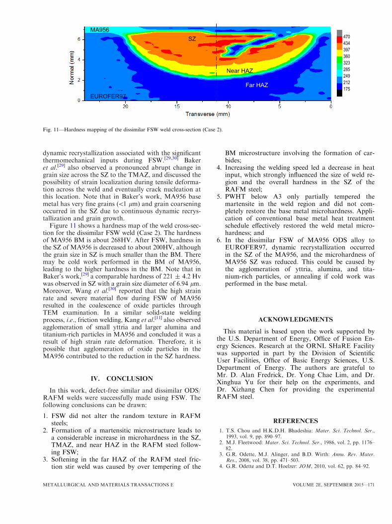
dynamic recrystallization associated with the significantthermomechanical inputs during FSW.[29,30] Bakeret al.[29] also observed a pronounced abrupt change ingrain size across the SZ to the TMAZ, and discussed thepossibility of strain localization during tensile deforma-tion across the weld and eventually crack nucleation atthis location. Note that in Baker’s work, MA956 basemetal has very fine grains (<1 lm) and grain coarseningoccurred in the SZ due to continuous dynamic recrys-tallization and grain growth.
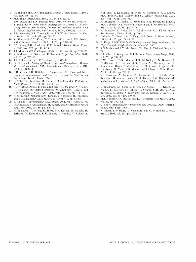
Figure 11 shows a hardness map of the weld cross-sec-tion for the dissimilar FSW weld (Case 2). The hardnessof MA956 BM is about 268HV. After FSW, hardness inthe SZ of MA956 is decreased to about 200HV, althoughthe grain size in SZ is much smaller than the BM. Theremay be cold work performed in the BM of MA956,leading to the higher hardness in the BM. Note that inBaker’s work,[29] a comparable hardness of 221 ± 4.2 Hvwas observed in SZ with a grain size diameter of 6.94 lm.Moreover, Wang et al.[30] reported that the high strainrate and severe material flow during FSW of MA956resulted in the coalescence of oxide particles throughTEM examination. In a similar solid-state weldingprocess, i.e., friction welding, Kang et al.[11] also observedagglomeration of small yttria and larger alumina andtitanium-rich particles in MA956 and concluded it was aresult of high strain rate deformation. Therefore, it ispossible that agglomeration of oxide particles in theMA956 contributed to the reduction in the SZ hardness.
IV. CONCLUSION
In this work, defect-free similar and dissimilar ODS/RAFM welds were successfully made using FSW. Thefollowing conclusions can be drawn:
1. FSW did not alter the random texture in RAFMsteels;
2. Formation of a martensitic microstructure leads toa considerable increase in microhardness in the SZ,TMAZ, and near HAZ in the RAFM steel follow-ing FSW;
3. Softening in the far HAZ of the RAFM steel fric-tion stir weld was caused by over tempering of the
BM microstructure involving the formation of car-bides;
4. Increasing the welding speed led a decrease in heatinput, which strongly influenced the size of weld re-gion and the overall hardness in the SZ of theRAFM steel;
5. PWHT below A3 only partially tempered themartensite in the weld region and did not com-pletely restore the base metal microhardness. Appli-cation of conventional base metal heat treatmentschedule effectively restored the weld metal micro-hardness; and
6. In the dissimilar FSW of MA956 ODS alloy toEUROFER97, dynamic recrystallization occurredin the SZ of the MA956, and the microhardness ofMA956 SZ was reduced. This could be caused bythe agglomeration of yttria, alumina, and tita-nium-rich particles, or annealing if cold work wasperformed in the base metal.
ACKNOWLEDGMENTS
This material is based upon the work supported bythe U.S. Department of Energy, Office of Fusion En-ergy Sciences. Research at the ORNL SHaRE Facilitywas supported in part by the Division of ScientificUser Facilities, Office of Basic Energy Sciences, U.S.Department of Energy. The authors are grateful toMr. D. Alan Fredrick, Dr. Yong Chae Lim, and Dr.Xinghua Yu for their help on the experiments, andDr. Xizhang Chen for providing the experimentalRAFM steel.
REFERENCES1. T.S. Chou and H.K.D.H. Bhadeshia: Mater. Sci. Technol. Ser.,
1993, vol. 9, pp. 890–97.2. M.J. Fleetwood: Mater. Sci. Technol. Ser., 1986, vol. 2, pp. 1176–
82.3. G.R. Odette, M.J. Alinger, and B.D. Wirth: Annu. Rev. Mater.
Res., 2008, vol. 38, pp. 471–503.4. G.R. Odette and D.T. Hoelzer: JOM, 2010, vol. 62, pp. 84–92.
MA956
EUROFER97
SZ
Near HAZ
Far HAZ
470434397360323285249212175
Fig. 11—Hardness mapping of the dissimilar FSW weld cross-section (Case 2).
METALLURGICAL AND MATERIALS TRANSACTIONS E VOLUME 2E, SEPTEMBER 2015—171
5. W. Sha and H.K.D.H. Bhadeshia: Metall. Mater. Trans. A, 1994,vol. 25A, pp. 705–14.
6. M.J. Shaw: Metallurgia, 1987, vol. 54, pp. S32–33.7. B.W. Baker and L.N. Brewer: JOM, 2014, vol. 66, pp. 2442–57.8. Z. Feng and W. Ren: Initial Investigation on Joining ODS Alloy
Using Friction Stir Welding for Gen IV Nuclear Reactor HeatExchanger Applications, San Antonio, Texas, 2007, pp. 431–38.
9. P.D. Sketchley, P.L. Threadgill, and I.G. Wright: Mater. Sci. Eng.A Struct., 2002, vol. 329, pp. 756–62.
10. K. Shinozaki, C.Y. Kang, Y.C. Kim, M. Aritoshi, T.H. North,and Y. Nakao: Weld. J., 1997, vol. 76, pp. S289–99.
11. C.Y. Kang, T.H. North, and D.D. Perovic: Metall. Mater. Trans.A, 1996, vol. 27A, pp. 4019–29.
12. T.J. Moore and T.K. Glasgow: Weld. J., 1985, vol. 64, pp. S219–26.13. K. Nishimoto, K. Saida, and R. Tsuduki: J. Jpn. Inst. Met., 2001,
vol. 65, pp. 756–65.14. T.J. Kelly: Weld. J., 1982, vol. 61, pp. S317–19.15. D. O’Donnell: Joining of Oxide-Dispersion-Strengthened Materi-
als, ASM Handbook, ASM International, Materials Park, OH,1993, pp. 1037–40.
16. L.R. Zirker, J.H. Bottcher, S. Shikakura, C.L. Tsai, and M.L.Hamilton: International Conference on Fast Reactor Systems andFuel Cycles, Kyoto, Japan, 1991.
17. P. Aubert, F. Tavassoli, M. Rieth, E. Diegele, and Y. Poitevin: J.Nucl. Mater., 2011, vol. 417, pp. 43–50.
18. R.J.Kurtz,A.Alamo,E.Lucon,Q.Huang, S. Jitsukawa,A.Kimura,R.L. Klueh, G.R. Odette, C. Petersen, M.A. Sokolov, P. Spatig, andJ.W. Rensman: J. Nucl. Mater., 2009, vols. 386–388, pp. 411–17.
19. H. Serizawa, S.Nakamura,M.Tanaka,Y.Kawahito,H. Tanigawa,and S. Katayama: J. Nucl. Mater., 2011, vol. 417, pp. 55–58.
20. B. Raj and T. Jayakumar: J. Nucl. Mater., 2011, vol. 417, pp. 72–76.21. G Srinivasan, B Arivazhagan, SK Albert, and AK Bhaduri: Fusion
Eng. Des., 2011, vol. 86, pp. 446–451.22. H. Tanigawa, T. Hirose, K. Shiba, B.R. Kasada, E. Wakaia, H.
Serizawa, Y. Kawahito, S. Jitsukawa, A. Kimura, Y. Kohno, A.
Kohyama, S. Katayama, H. Mori, K. Nishimoto, R.L. Klueh,M.A. Sokolov, R.E. Stoller, and S.J. Zinkle: Fusion Eng. Des.,2008, vol. 83, pp. 1471–76.
23. H. Tanigawa, K. Shiba, A. Moeslang, R.E. Stoller, R. Lindau,M.A. Sokolov, G.R. Odette, R.J. Kurtz, and S. Jitsukawa: J. Nucl.Mater., 2011, vol. 417, pp. 9–15.
24. H. Tanigawa, K. Shiba, M.A. Sokolov, and R.L. Klueh: FusionSci. Technol., 2003, vol. 44, pp. 206–10.
25. J. Gould, T. Linert, and Z. Feng: SAE Trans. J. Mater. Manuf.,1998, vol. 107, pp. 1093–1100.
26. Z. Feng: EERE Vehicle Technology Annual Progress Reports forHigh Strength Weight Reduction Materials, 2005.
27. R.S. Mishra and Z.Y. Ma:Mater. Sci. Eng. R, 2005, vol. 50, pp. 1–78.
28. C.L. Chen, P. Wang, and G.J. Tatlock: Mater. High Temp., 2009,vol. 26, pp. 299–303.
29. B.W. Baker, E.S.K. Menon, T.R. McNelley, L.N. Brewer, B.EL-Dasher, J.C. Farmer, S.G. Torres, M. Mahoney, and S.Sanderson: Metall. Mater. Trans. E, 2014, vol. 1E, pp. 318–30.
30. J.Y. Wang, W. Yuan, R.S. Mishra, and I. Charit: J. Nucl. Mater.,2013, vol. 432, pp. 274–80.
31. S. Jitsukawa, A. Kimura, A. Kohyama, R.L. Klueh, A.A.Tavassoli, B. van der Schaaf, G.R. Odette, J.W. Rensman, M.Victoria, and C. Petersen: J. Nucl. Mater., 2004, vol. 329, pp. 39–46.
32. S. Jitsukawa, M. Tamura, B. van der Schaaf, R.L. Klueh, A.Alamo, C. Petersen, M. Schirra, P. Spaetig, G.R. Odette, A.A.Tavassoli, K. Shiba, A. Kohyama, and A. Kimura: J. Nucl. Ma-ter., 2002, vol. 307, pp. 179–86.
33. M.J. Alinger, G.R. Odette, and D.T. Hoelzer: Acta Mater., 2009,vol. 57, pp. 392–406.
34. V Voort: Metallography Principles and Practice, ASM Interna-tional, New York, 1999.
35. N. Inoue, T. Muroga, A. Nishimura, and O. Motojima: J. Nucl.Mater., 1998, vol. 258, pp. 1248–52.
172—VOLUME 2E, SEPTEMBER 2015 METALLURGICAL AND MATERIALS TRANSACTIONS E