Embed Size (px)
Citation preview

*DE01925'2'414* FRO30122311V
ETHANOLAMINE EXPERIENCE AT KOEBERG NUCLEAR POWER STATION,SOUTH AFRICA
KJ. GALT; ESKOM ENTERPRISES,TECHNOLOGY SERVICES INTERNATIONAL DIVISION
NB CARIS; ESKOM, KOEBERG NUCLEAR POWER STATION
ABSTRACT
Following testing of ethanolarnine as an alternative to ammonia on Unit 2 in 1997, Unit of the Koeberg NuclearPower Station was converted to ethanolarnine in 1998. The Unit has now operated for just over one and a halfcycle on ETA. The decision to change to ETA was made to achieve further reductions in feedwater irontransport.
Koeberg has always operated ammonia/hydrazine AVT control and ran the feedwater pH at 96 9.7 before thechangeover. The original pH levels were increased in response to concerns over flow-accelerated corrosion. Aby product of reducing the FAC rates is a reduction in iron transport. Although nominally all-ferrous, there are anumber of small copper-containing components and the Koeberg Engineering Department would notcountenance a further increase in ammonia concentrations in case of copper transport to the SGs. This led toethanolamine being selected as an alternative to ammonia.
The Koeberg condensate polishing plant has been modified, largely to accommodate ETA operation, but is notcurrently operable in the modified configuration. It is therefore on standby while ETA is implemented. The SGblowdown dernineralisers have begun to be operated past ammonia/ETA break, but optimisation is largelydependent on CPP availability in the modified configuration.
This paper documents the Koeberg experience to date of operation under an ethanolamine-AVT regime. Asone of the few plants outside of the USA to have changed to ethanolamine, it is hoped we can make a valuablecontribution for other non-US plants considering such a move.

INTRODUCTION
Eskom, the national utility company of South Africa owns and operates 39154 MW of electric power productioncapacity, of which the major portion by far, 34882 MW, is provided by just ten very large coal-fired stations.Nuclear power currently constitutes only 1930 MW - or 49% - of the total installed capacity. All of the nuclearcapacity is located at the Koeberg Nuclear Power Station (figure 1), some 35 km north of Cape Town on thewest, or Atlantic, coast of South Africa. Koeberg is a twin 965 MW, Framatome built (Westinghouse-type), PWR
station. The cold South Atlantic BenguelaCurrent supplies seawater for condensercooling.
The plant was originally started up underammonia hydrazine all volatile treatment(AVT) and has operated in this mode untilrecently. Concerns over flow-acceleratedcorrosion (FAC) have resulted in changes to
i the ammonia hydrazine chemistry over theyears. The inspection and monitoringprogramme that began in the second half ofthe 1980's confirmed that two-phase FACwas the major problem confronting Koebergand identified the moisture-separatorreheaters as probably the most affectedcomponent at that stage. Although the rateof wall thinning was estimated to be muchless than had been observed on Electricit6
IMENIM1110 de France Units at a similar stage ofFigure operating life, attributable mainly to the
Koeberg Nuclear Power Station higher pH's operated at Koeberg,nevertheless it remained a concern.Modifications, repairs and/or replacement ofthe moisture-separator reheaters (MSR's)
and a number of smaller components have taken place, but changes to the applied chemistry regime wereclearly required.
Morpholine treatment had been considered as an alternative to ammonia, partly because of our close ties withElectricit6 de France (EdF), who had reported good experience with morpholine and had converted the majorityof their units to this chemistry. However, at the time the Koeberg policy was to maintain condensate polisheroperation, installed at Koeberg but not on EdF PWRs, and morpholine treatment would have compromisedcondensate polisher operation this position; as a result, morpholine was rejected.,. The operating philosophywith respect to the condensate polishers was later amended to start-up under full flow, but partial flow orstandby for normal operation. This allowed the ammonia concentration to be increased to obtain the highestfeedwater pH then allowed by the specifications, pH25 =9.7.
In the mid-1990's, good experience feedback from the USA, where a large number of plants had converted toethanolamine, persuaded us to convert to this amine. Testing began on Unit 2 in 1997 and the permanentswitchover to ethanolamine of Unit took place in late 1998. About one and one half complete fuel cycles ofETA operating experience have now accrued on Unit .
The permanent switchover of Unit 2 was delayed because the Unit developed a very small condenser leak andthe polisher was returned to service. This leak proved extremely difficult to isolate and it was only at the end of2001 that Unit 2 was finally converted to ETA operation. In mid-2001 the blowdown treatment resins of Unit were allowed to operate past amine break for the first time.
Implementation of ethanolamine treatment at Koeberg has been described previously('). However, as the onlyFramatome-built Station to have definitively adopted ethanolamine treatment as the preferred regime, and oneof the few outside of the USA, it was felt opportune to provide feedback on our experience to date to thisConferencea nd perhaps assist other plants considering such a change.
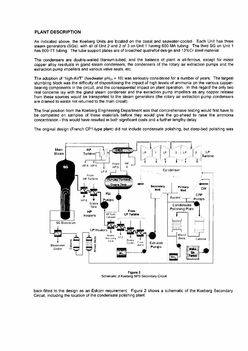
PLANT DESCRIPTION
As indicated above, the Koeberg Units are Iccated on the coast and seawater-cooled. Each Unit has threesteam generators (SGs), with all of Unit 2 and 2 of 3 on Unit aving 600-MA tubing. The third SG on Unit has 600-TT tubing. The tube support plates are of broached quatrefoil design and 13%Cr steel material.
The condensers are double-walled titanium-tubed, and the balance of plant is all-ferrous, except for minorcopper alloy residuals in gland steam condensers, the condensers of the rotary air extraction pumps and theextraction pump impellers and various valve seats, etc.
The adoption of "high-AVT" (feedwater pl-12 = 10) was seriously considered for a number of years. The largeststumbling block was the difficulty of dispositioning the impact of high levels of ammonia on the various copper-bearing components in the circuit, and the consequential impact on plant operation. In this regard the only tworeal concerns lay with the gland steam condenser and the extraction pump impellers as any copper releasefrom these sources would be transported to the steam generators (the rotary air extraction pump condensersare drained to waste not returned to the main circuit).
The final position from the Koeberg Engineering Department was that comprehensive testing would first have tobe completed on samples of these materials before they would give the go-ahead to raise the ammoniaconcentration - this would have resulted in botl� significant costs nd a further lengthy delay.
The original design (French CP1-type plant) did not include condensate polishing, but deep-bed polishing was
Win HpSteam Turbine LP LP LP 3 LP
Turbine
HP6 HP5 FromH PI 6�)L 4 Condenser
FromHP Turbine
Secondary Primary CWWell Well
L -B y-p a s s CPPPumps -I--, Pumps
i n CondensateTank Polishing Pion
HP FromHeaters LP TurbineF E A, most
SG Blowdown
LP Heaters
Nain. MXedec ovey P Beds CationsTank
C.nd ExtractnBI d Pumps
Cool U
NOW
Figure 2Schernalic of Koeberg NPS Secondary Circuit
back-fitted to the design as an Eskom requirement. Figure 2 shows a schematic of the Koeberg SecondaryCircuit, including the location of the condensate polishing plant.
CONDENSATE POLISHER OPERATION
The condensate polishing plant was designed as a 100./full-flow system and it operated in this mode during earl;commercial operation 1984 - 1985). The plant consists offive lead cation vessels followed, after a common cationoutlet header, by five mixed bed vessels. The mixed bedvessels can be seen in Figure 3.
Each vessel was designed for 25% flow, but modifications tothe location within the condenser of the low-pressure h eat erdrains return lines during construction resulted in thisreducing to 20%. The polisher booster pumps wereeffectively down-rated by this modification from 3 x 50% dutyto 3 x 40%, i.e. all 3 had to be in service for the modified full-flow of 3760 t.h-'. A sixth charge of cation and mixed resin isretained in the post regeneration storage vessels of theremote regeneration station. The polishers are operated in Figure 3
the hydrogen hydroxide mode only. CPP Mixed Bed Vessels Unit
To accommodate the increased ammoniaconcentrations associated with increased ow cano"w - - ----
Ffm:wnfeedwater pH, partial flow operation was Coh&rallr
adopted. Further feedwater pH increases sawthe polisher placed in standby mode in 1994,used only in "emergency" situations andstartups. Cal Cal Cat at
04 03 E, 02F1 ri F1
Later (mid-late 1990s) modifications to the rv 7Fpolishing plants allowed them to be placed in abypass mode with a continuous conditionin Malflow for rapid return to service. Testing of thisg
Fl Flsystem gave a 45 second return to fullpolishing mode from essentially zero olishingwith no prior resin rinse down requirement.
It had been intended that the polishing plantmodifications would be complete. Prior to C n
implementation of ETA treatment, This wouldthen have allowed the steam generator Figure 4
blowdown treatment resins to be operated past Schernatic of CPP Layout
arnine breakpoint without being concernedabout ionic leakage from these resins. However, because of as yet unresolved control and logic problems,coupled to very sever financial constraints, the condensate polishers have not operated in this conditionedbypass mode and are instead placed on standby
TREATMENT HISTORY
Since commercial operation began in 1984, Koeberg has employed all volatile chemistry, using ammonia for pHcontrol and hydrazine for oxygen scavenging and as a reducing agent.
The original hydrazine requirement was a minimum of five times the ondensate dissolved oxygen-, however, inthe early 1990's this was changed to a minimum of 100 pg.kg-l with a target of > 120 �tg.kg_' and a nominalupper limit of 150 pg.kg-'. We are currently in the process of changing this to a minimum of 50 �tg.kg-l with anupper limit of 80 pg.kg-l and a target range of 60 - 75 �tg.kg_'.
The feedwater pH control history is more varied and summarised as follows (always under ammonia addition,unless otherwise stated)�
1984/85

A pH range of 8.8 to 92 had been specified by the French consortium that built the plants. The Eskompreference was to operate at the maximum of this range and so both Units were commissioned at 92.
1985 - 1989
Since the feedtrain is "all-ferrous", the feedwater pH was increased to 94 almost immediately aftercommercial operation began. The limitation on feedwater pH was polishing plant resin loading rate andresin regeneration turnaround capability. At this time the polishers were operated in the 100%condensate flow mode.
1989-1998 (Unit / 2001 (Unit 2)
The feedwater pH was raised to .6 - 97. The polisher was placed in standby or partial flow asnecessary to control steam generator chemistry and maintain pH 97 operation. If full-flow polishingbecame necessary, the feed pH would be reduced to 94 - 95 - the maximum that we could manageunder full-flow polishing.
1998 - Date (Unit )
Ethanolamine replaced ammonia as the pH conditioning agent. Testing of the unit on ETA began in 1998and the unit was converted in 1999. The condensate polisher was placed in standby mode. If polisheroperation was required, the unit would revert to ammonia conditioning at pH25 95 for full-flow or 97 forpartial-flow. This was dictated by cost rather than chemistry considerations.
The SG blowdown polishers have been operated in the hydrogen hydroxide form. In mid-2001 theresins on Unit were allowed to operate past the arnine break for the first time. Part of the rational of theearlier condensate polisher modifications, allowing conditioning of the resins while on standby, was tofacilitate amine-form operation on the blowdown treatment resins (see below). However, because ofunresolved control and logic problems, the condensate polishers have not operated in this conditionedbypass mode and are instead placed on standby. The decision to implement arnine form operationwithout the bypass/recirculation mode of the polishers thus implies acceptance of a probable deteriorationin SG water quality. However, violation of the Eskom (Koeberg) Secondary Chemistry standards will notbe permitted and the resins will be changed before increasing ionic leakage from the blowdown treatmentresins makes this a possibility.
ETA CHEMICAL STORAGE AND INJECTION SYSTEM
Before implementing the ETA regime, a reviewof the installed chemical storage and injectionequipment concluded that the existing chemicaldosing stations were unsuitable and thatcustom built facility was required. The newpurpose-built ETA dosing plant was installed inthe turbine hall near to the existing chemicalinjection room. The basic layout of the ant is 'm WMillustrated is Figure 5. b��'
WON3Each of the two units has its own 1.5 ETA
tank with two injection pumps in parallel for pmurr Rel umredundancy. These pumps can deliver a WdN mmtflowrate up to 10 Uhr. The tank is batched bymeans of a plumbed-in portable pump whichtransfers the contents of 200 litre drums of 98%ETA. It was found to be convenient to use justone full drum when batching up the tank whichresults in a tank concentration of approximately14%. An injection flowrate of approximately 2.5Uhr achieves an ETA concentration of 4 ppm Figure 5(mg/kg) in the heater drains tank (HDT) under Schematic of ETA Dosing System
normal plant conditions.

A nitrogen atmosphere at 10 kPa (gauge) is maintained in the tank gas space, with the supply from a commonnitrogen cylinder 20 MPa) located just outside the room. As indicated in Figure 5 a simple dual-purposepressure relief column is provided. Its function is to contain the nitrogen under normal operation but to allow thenitrogen to vent out during tank batching, Furthermore, as the ETA tank is not a rated pressure vessel, thisventing column was designed to allow the free flow of the liquid contents of the tank in the event that the tank isoverfilled with dernineralised water. (The system pressure of the demineralised water supply system is 850kPa.) An orifice was also fitted in the water supply line to limit the flow to 50 Urnin.
Downstream of the two injection pumps are two flow meters; one low-range and one high-range. From there,the injection line is plumbed into the feedwater just downstream of the condensate extraction pumps.
The ETA injection system was designed to operate with the CPP system in bypass/recirculation mode and is notsized to maintain ETA concentrations around the circuit if the CPP is in operation (ETA being removed on thelead cations). Therefore, in the event of the polishers entering service, the Unit will revert to ammonia AVT andETA dosing will cease during that period - this was the intent, but since the ETA dosing plant is under manualcontrol, injection at the previous level could continue. This decision was taken on purely economic grounds asall ETA supplies are shipped in from the USA.
ETA SPECIFICATIONS AND DISTRIBUTION
The original testwork utilised an ETA concentration of 3 mg.kg-1, as measured at the heater drains tank, as thebasis of the specification. This was considered sufficient to ensure an elevation of pH unit above neutral inthe most affected two phase areas (moisture separator-reheaters and bled steam lines to the second stage highpressure heaters).
Control of ETA treatment was based on the feedwater pH, which was maintained at between pH 95 and 97,the injection rate being varied manually by varying the pump stroke as required. This was selected because pHmeasurement was already in place.
The feedwater ammonia concentration as a result of hydrazine breakdown is typically mg.kg_1 (as NH3) withthe CPP on standby. Although it had long been recognised that hydrazine breakdown contributed ammonia, itwas only with the placing of the polishers in standby mode that it was realised how significant that contributioncould be.
The ETA concentration of 3 mg.kg-1 gave a feedwater ETA concentration of 2 - 3 mg.kg-1. The estimatedfeedwater pHs were then determined using the ETA and ammonia concentrations. Feedweater pH continued tobe used for control purposes. A series of ammonia/ETA pH and conductivity correlatory charts were preparedto assist the plant chemist in the control of the system. These work reasonably well when used; unfortunatelythere is a tendency for the plant chemists to ignore them and focus only on pH control and they are used mainlyby laboratory analysts for QC purposes. Controlling only on pH can lead to underdosing of ETA and we wish toavoid this in future. Consequently, we are changing the Eskom (Koeberg) Secondary Chemistry Standards toreflect an ETA concentration range of 3 - 6 mg.kg-1 in the feedwater, rather than the current pH range.
The minimum of the range was based on a re-analysis of the ETA distribution around the Koeberg circuit.These results were compared to calculated values. These were found to be in reasonably good agreement.The "at temperature" pH was then calculated at various points, using the ammonia/ETA/hydrazineconcentrations typical of the Koeberg circuit, and compared to the calculated neutral pH. As indicated, thetypical ammonia concentration for a feedwater hydrazine of 120 pg.ky'l was mg.kg-1. From this it was foundthat the minimum feedwater ETA concentration required was 3 mg.kg' .
The results for 3 mg.kg-1 are reproduced in table below.
The calculated ETA distribution around the secondary systems and the resulting pHs, as given in Table weredetermined using an in-house developed MicrosoftT1,1 Excel based spreadsheet application, which takes partitioncoefficients into account for two-phase conditions. The thermodynamic data used was based on values givenby Miller (2� . The calculations were performed when the unit was at 71% power; unfortunately the spreadsheetonly allows for full power operation. Given that agreement between the measured and calculated values wasconsidered to be reasonably good
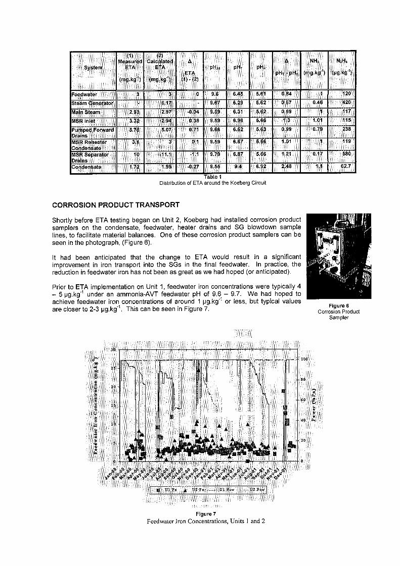
3
ETA' PHZS MT� P"n
ETA PM H
in 1� J2
Fee ter#�o I 1� � I �j 1�1� � 9.6 6.46 84 1�� 1� U 201
Steam Grat r ��6� l� 6.29� 6.62 0.67 0 4200 ii� t I
9Main 26�3 I 7N D4! 9.5 31 ��15.62 61 ld�7 911
MSR inlet' 13; 2094 OM 9.59 �i% 6096 �1 .66 C4 Y1.016 2 6 79 238
Pumped FoMard! �J� V8 �I 1 9.66 0.DrainaLLN ��MIVISRRpheater 61 01 119C�ndensato i Til�MSR Sparator,, 21brains
on n to IJ2 �5 9.4 6.92 2�48 1.1 62
Table Distribution of ETA around the Koeberg Circuit
CORROSION PRODUCT TRANSPORT
Shortly before ETA testing began on Unit 2 Koeberg had installed corrosion prod uctsamplers on the condensate, feedwater, heater drains and SG blowdown am plelines, to facilitate material balances. One of these corrosion product samplers can beseen in the photograph, (Figure 6.
It had been anticipated that the change to ETA would result in a significantimprovement in iron transport into the SGs in the final feedwater. In practice, thereduction in feedwater iron has not been as great as we had hoped (or anticipated).
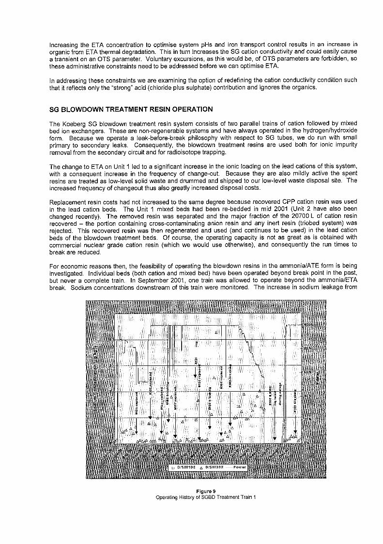
Prior to ETA implementation on Unit 1, feedwater iron concentrations were typically 4- 5 pg.kg-1 under an ammonia-AVT feedwater pH of 96 - 97. We had hoped toachieve feedwater iron concentrations of around 1 pg.kg-1 or less, but typical values Figure 6are closer to 23 pg.kg-1. This can be seen in Figure 7 Corrosion Product
Sampler
2
16"
A� -
�A
�. e�
Figure 7Feedwater Iron Concentrations, Units I and 2
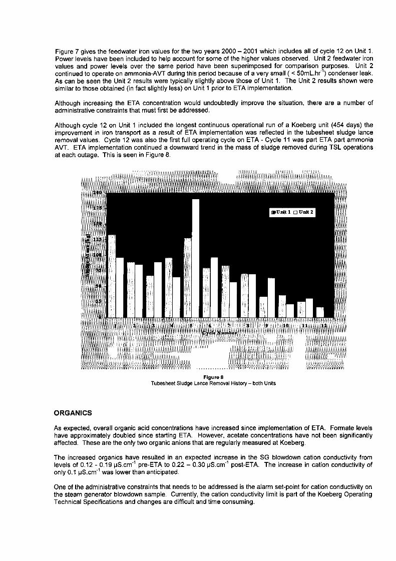
Figure 7 gives the feedwater iron values for the two years 2000 - 2001 which includes all of cycle 12 on Unit .Power levels have been included to help account for some of the higher values observed. Unit 2 feedwater ironvalues and power levels over the same period have been superimposed for comparison purposes. Unit 2continued to operate on ammonia-AVT during this period because of a very small < 5mL.hr_) condenser leak.As can be seen the Unit 2 results were typically slightly above those of Unit 1. The Unit 2 results shown weresimilar to those obtained (in fact slightly less) on Unit prior to ETA implementation.
Although increasing the ETA concentration would undoubtedly improve the situation, there are a number ofadministrative constraints that must first be addressed.
Although cycle 12 on Unit included the longest continuous operational run of a Koeberg unit 454 days) theimprovement in iron transport as a result of ETA implementation was reflected in the tubesheet sludge lanceremoval values. Cycle 12 was also the first full operating cycle on ETA - Cycle 1 1 was part ETA part ammoniaAVT. ETA implementation continued a downward trend in the mass of sludge removed during TSL operationsat each outage. This is seen in Figure .
RN
Maine
Figure 8Tubesheet Sludge Lance Removal History - both Units
ORGANICS
As expected, overall organic acid concentrations have increased since implementation of ETA. Formate levelshave approximately doubled since starting ETA. However, acetate concentrations have not been significantlyaffected. These are the only two organic anions that are regularly measured at Koeberg.
The increased organics have resulted in an expected increase in the SG blowdown cation conductivity fromlevels of 012 - 019 pS.cm" pre-ETA to 022 - 030 pS.cm-1 post-ETA. The increase in cation conductivity ofonly 0.1 pS.cm" was lower than anticipated.
One of the administrative constraints that needs to be addressed is the alarm set-point for cation conductivity on
the steam generator blowdown sample. Currently, the cation conductivity limit is part of the Koeberg OperatingTechnical Specifications and changes are difficult and time consuming.
Increasing the ETA concentration to optimise system pHs and iron transport control results in an increase inorganic from ETA thermal degradation. This in turn increases the SG cation conductivity and could easily causea transient on an OTS parameter. Voluntary excursions, as this would be, of OTS parameters are forbidden, sothese administrative constraints need to be addressed before we can optimise ETA.
In addressing these constraints we are examining the option of redefining the cation conductivity condition suchthat it reflects only the "strong" acid (chloride plus sulphate) contribution and ignores the organics.
SG BLOWDOWN TREATMENT RESIN OPERATION
The Koeberg SG blowdown treatment resin system consists of two parallel trains of cation followed by mixedbed ion exchangers. These are non-regenerable systems and have always operated in the hydrogen/hydroxideform. Because we operate a leak-before-break philosophy with respect to SG tubes, we do run with smallprimary to secondary leaks. Consequently, the blowdown treatment resins are used both for ionic impurityremoval from the secondary circuit and for radioisotope trapping.
The change to ETA on Unit led to a significant increase in the ionic loading on the lead cations of this system,with a consequent increase in the frequency of change-out. Because they are also mildly active the spentresins are treated as low-level solid waste and drummed and shipped to our low-level waste disposal site. Theincreased frequency of changeout thus also greatly increased disposal costs.
Replacement resin costs had not increased to the same degree because recovered CPP cation resin was usedin the lead cation beds. The Unit mixed beds had been re-bedded in mid 2001 (Unit 2 have also beenchanged recently). The removed resin was separated and the major fraction of the 20700 L of cation resinrecovered - the portion containing cross-contaminating anion resin and any inert resin (triobed system) wasrejected. This recovered resin was then regenerated and used (and continues to be used) in the lead cationbeds of the blowdown treatment beds. Of course, the operating capacity is not as great as is obtained withcommercial nuclear grade cation resin (which we would use otherwise), and consequently the run times tobreak are reduced.
For economic reasons then, the feasibility of operating the blowdown resins in the ammonia/ATE form is beinginvestigated. Individual beds (both cation and mixed bed) have been operated beyond break point in the past,but never a complete train. In September 2001, one train was allowed to operate beyond the ammonia/ETAbreak. Sodium concentrations downstream of this train were monitored. The increase in sodium leakage from
Italy �1 �A
to
E
Al I
A 4,
A)
L A� 'A
0 DS091DE /S003D
Figure 9Operating History of SGBD Treatment Train I
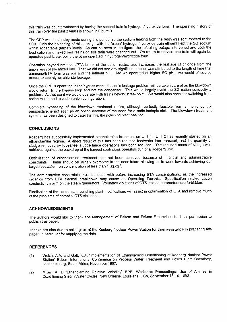
this train was counterbalanced by having the second train in hydrogen/hydroxide form. The operating history ofthis train over the past 2 years is shown in Figure 9.
The CPP was in standby mode during this period, so the sodium leaking from the resin was sent forward to theSGs. Only the balancing of this leakage with the "clean" hydrogen/hydroxide train effluent kept the SG sodiumwithin acceptable (target) levels. As can be seen in the figure, the refuelling outage intervened and both thelead cation and mixed bed resins on this train were changed out. On return to service one train will again beoperated past break point, the other operated in hydrogen/hydroxide form.
Operation beyond ammonia/ETA break of the cation resins also increases the leakage of chloride from theanion resin of the mixed bed. That we did not see any significant impact was attributed to the length of time thatammonia/ETA form was run and the influent pH. Had we operated at higher SG pHs, we would of courseexpect to see higher chloride leakage,
Once the CPP is operating in the bypass mode, the ionic leakage problem will be taken care of as the blowdownwould return to the bypass loop and not the condenser. This would largely avoid the SG cation conductivityproblem. At that point we would operate both trains beyond breakpoint. We would also consider switching fromcation mixed bed to cation anion configuration.
Complete bypassing of the blowdown treatment resins, although perfectly feasible from an ionic controlperspective, is not seen as an option because of the need for a radio-isotopic sink. The blowdown treatmentsystem has been designed to cater for this, the polishing plant has not.
CONCLUSIONS
Koeberg has successfully implemented ethanolamine treatment on Unit 1. Unit 2 has recently started on anethanolamine regime. A direct result of this has been reduced feedwater iron transport, and the quantity ofsludge removed by tubesheet sludge lance operations has been reduced. The reduced mass of sludge wasachieved against the backdrop of the longest continuous operating run of a Koeberg unit.
Optimisation of ethanolamine treatment has not been achieved because of financial and administrativeconstraints. These should be largely overcome in the near future allowing us to work towards achieving ourtarget feedwater iron concentration of less than pg.kg-1.
The administrative constraints must be dealt with before increasing ETA concentrations, as the increasedorganics from ETA thermal breakdown may cause an Operating Technical Specification related cationconductivity alarm on the steam generators. Voluntary violations of OTS-related parameters are forbidden.
Finalisation of the condensate polishing plant modifications will assist in optimisation of ETA and remove muchof the problems of potential OTS violations.
ACKNOWLEDGMENTS
The authors would like to thank the Management of Eskom and Eskom Enterprises for their permission topublish this paper.
Thanks are also due to colleagues at the Koeberg Nuclear Power Station for their assistance in preparing thispaper, in particular for supplying the data.
REFERENCES
(1) Welsh, A.A. and Galt, K.J.; "Implementation of Ethanolamine Conditioning at Koeberg Nuclear PowerStation" Eskom International Conference on Process Water Treatment and Power Plant Chemistry,Johannesburg, South Africa, November 1997.
(2) Miller, A. D.;"Ethanolamine Relative Volatility" EPRI Workshop Proceedings: Use of Amines inConditioning Stearn/Water Cycles, New Orleans, Louisiana, USA, September 13-14, 1993.


![Requirements for Protective Coatings for use at Koeberg ... · Requirements for Protective Coatings for use at Koeberg Nuclear Power Station CONTROLLED DISCLOSURE ... [26] BS EN ISO](https://img.pdfslide.net/doc/110x75/5c6027fb09d3f263278b47e4/requirements-for-protective-coatings-for-use-at-koeberg-requirements-for.jpg)

![[XLS] · Web viewPATEL RUCHIT RAMESHCHANDRA 11V-100303 DESAI RACHIT KEYUR 11V-100275 PITRODA NIDHI NILESH 11V-100221 SHAH DEEP MAHIPALBHAI](https://img.pdfslide.net/doc/110x75/5aa38cd17f8b9ada698e5fe9/xls-viewpatel-ruchit-rameshchandra-11v-100303-desai-rachit-keyur-11v-100275-pitroda.jpg)