Embed Size (px)
Citation preview

g:\aproject\lockheed\utica\reports\solvent dock\qapp\revised august 2009\draft final qappdec\transmittal letter.doc
Page:
1/1
To: Copies:
Mr. Larry Rosenmann NYSDEC Bureau of Hazardous Waste and Radiation Management, 9
th Floor
625 Broadway Albany, NY 12233
Greg Rys, NYSDOH
Tom Blackman, Lockheed Martin
James Zigmont, CDM
Chris Motta, ARCADIS
Ginny Robbins, BSK
Kay Armstrong, Armstrong &
Associates
Dale Truskett, Lockheed Martin
File
From: Date:
Lisa Collins October 14, 2009
Subject: ARCADIS Project No.:
Quality Assurance Project Plan NJ000643.0001
We are sending you: Attached Under Separate Cover Via the Following Items:
Shop Drawings Plans Specifications Change Order
Prints Samples Copy of Letter Reports
Other:
Copies Date Drawing No. Rev. Description Action*
1 10/14/09 Quality Assurance Project Plan, Solvent Dock Area, Former French Road Facility, Utica, New York
Action*
A Approved CR Correct and Resubmit Resubmit Copies
AN Approved As Noted F File Return Copies
AS As Requested FA For Approval Review and Comment
Other: Mailing Method
U.S. Postal Service 1st Class Courier/Hand Delivery FedEx Priority Overnight FedEx 2-Day Delivery
Certified/Registered Mail United Parcel Service (UPS) FedEx Standard Overnight FedEx Economy
Other:
Comments:
ARCADIS
465 New Karner Road
First Floor
Albany
New York 12205-3839
Tel 518.452.7826
Fax 518.452.7086
Transmittal Letter

Imagine the result
Quality Assurance Project Plan
Solvent Dock Area
Former French Road Facility
Utica, New York
October 2009

Quality Assurance Project Plan Solvent Dock Area Former French Road Facility Utica, New York
Prepared for:
Lockheed Martin Corporation
Prepared by:
ARCADIS of New York, Inc.
465 New Karner Road
First Floor
Albany
New York 12205
Tel 518 452 7826
Fax 518 452 7086
Our Ref.:
NJ000643.0001
Date:
October 2009
This document is intended only for the use of
the individual or entity for which it was
prepared and may contain information that is
privileged, confidential, and exempt from
disclosure under applicable law. Any
dissemination, distribution, or copying of this
document is strictly prohibited.
Mary Ann Doyle Staff Scientist
Dennis Capria Principal Scientist
Jeffrey J. Bonsteel. Project Scientist
Christopher J. Motta, CPG Project Manager

i
Table of Contents
Table of Contents
Acronyms
Preface 1
1. Project Organization 3
1.1 Project Organization 3
1.1.1 Overall Project Management 3
1.1.2 Task Managers 4
1.2 Team Member Responsibilities 4
1.2.1 Lockheed Martin Corporation 4
1.2.2 ARCADIS 4
1.2.3 Analytical Laboratories 7
1.2.4 New York State Department of Environmental Conservation 7
1.2.5 Project Organization Chart 8
2. Project Background 9
2.1 Site Location and Description 9
2.2 Site History and Summary of Activities 9
3. Project Description 11
3.1 GCTS Monitoring Activities 11
3.2 Periodic Groundwater Sampling 11
3.3 Periodic Soil Gas and Indoor Air Sampling 12
3.4 SSDS Performance Sampling 12
3.5 Site Investigation Sampling 12
3.6 Approach 12
3.7 Project Schedule 12
4. Quality Objectives and Criteria for Measurement Data 13

ii
Table of Contents
4.1 Data Categories 14
4.2 Field Investigations 16
5. Special Training Requirements/Certification 17
6. Documentation and Records 18
6.1 General 18
6.2 Sample Designation System 18
6.2.1 Sample Codes 18
6.2.2 Field Documentation 19
6.3 Laboratory Documentation Files 20
6.3.1 Laboratory Project Files 20
6.3.2 Laboratory Logbooks 20
6.3.3 Computer Tape and Hard-Copy Storage 21
6.4 Data Reporting Requirements 21
6.4.1 Field Data Reporting 21
6.4.2 Laboratory Data Reporting 21
6.5 Project File 23
6.6 Sampling Process Design 23
7. Sampling Method Requirements 24
7.1 Sample Containers and Preservation 24
7.2 Field Custody Procedures 24
7.2.1 Field Logbooks 24
7.2.2 Sample Labeling 25
7.2.3 Field Chain-of-Custody Forms 26
7.3 Management of Investigation-Derived Materials and Wastes 27
7.4 Packing, Handling, and Shipping Requirements 27
7.5 Laboratory Custody Procedures 29

iii
Table of Contents
7.5.1 General 29
7.5.2 Sample Receipt and Storage 29
7.5.3 Sample Analysis 30
7.5.4 Sample Storage Following Analysis 30
8. Analytical-Method Requirements 31
8.1 Field Parameters and Methods 31
8.2 Laboratory Parameters and Methods 31
8.2.1 General 31
8.2.2 Supplemental Remedial Design Sample Matrices 31
8.2.3 Analytical Requirements 31
9. Quality Control Requirements 32
9.1 Quality Assurance Indictors 32
9.1.1 Representativeness 32
9.1.2 Comparability 33
9.1.3 Completeness 33
9.1.4 Precision 33
9.1.5 Accuracy 33
9.2 Field Quality Control Checks 34
9.2.1 Field Measurements 34
9.2.2 Sample Containers 34
9.2.3 Field Duplicates 34
9.2.4 Rinse Blanks 34
9.2.5 Trip Blanks 35
9.3 Analytical Laboratory Quality Control Checks 35
9.3.1 General 35
9.3.2 Method Blanks 35
9.3.3 Matrix Spike/Matrix Spike Duplicates 35

iv
Table of Contents
9.3.4 Surrogate Spikes 36
9.3.5 Laboratory Duplicates 36
9.3.6 Calibration Standards 36
9.3.7 Internal Standards 37
9.3.8 Reference Standards/Control Samples 37
9.4 Data Precision Assessment Procedures 37
9.5 Data Accuracy Assessment Procedures 38
9.6 Data Completeness Assessment Procedures 38
10. Instrument/Equipment Testing, Inspection, and Maintenance Requirements 39
10.1 General 39
10.2 Field Instruments and Equipment 39
10.2.1 Equipment Maintenance 39
10.3 Laboratory Instruments and Equipment 40
10.3.1 General 40
10.3.2 Instrument Maintenance 40
10.3.3 Equipment Monitoring 40
11. Instrument Calibration and Frequency 41
11.1 Field Instruments and Equipment 41
11.2 Laboratory Instrument and Equipment 41
12. Inspection/Acceptance Requirements for Supplies and Consumables 43
13. Data Acquisition Requirements for Non-Direct Measurements 44
14. Data Management 45
14.1 Sample Designation System 45
14.2 Field Activities 45
14.2.1 Field Documentation 46

v
Table of Contents
14.2.2 Data Security 47
14.3 Sample Management and Tracking 47
14.4 Data-Management System 48
14.4.1 Computer Hardware 48
14.4.2 Computer Software 48
14.4.3 Survey Information 48
14.4.4 Field Observations 49
14.4.5 Analytical Results 49
14.4.6 Data Analysis and Reporting 50
14.5 Document Control and Inventory 51
15. Assessment and Response Actions 53
15.1 General 53
15.2 Field Audits 53
15.3 Laboratory Audits 53
15.4 Corrective Action 54
15.4.1 Field Procedures 54
15.4.2 Laboratory Procedures 54
16. Reports to Management 55
16.1 Internal Reporting 55
16.2 Supplemental Remedial Design Reporting 56
17. Data Reduction and Review 57
17.1 General 57
17.2 Field Data Reduction and Review 57
17.2.1 Field Data Reduction 57
17.2.2 Field Data Review 57
17.3 Laboratory Data-Reduction and Review 58

vi
Table of Contents
17.3.1 Laboratory Data-Reduction 58
17.3.2 Laboratory Data Review 58
17.4 Data Validation and Verification 59
18. Data Validation and Verification 60
19. Reconciliation with User Requirements 62
20. References 63
Figures
1 Project Organization Chart
2 Site Location Map
Tables
1 Analytical Quality-Control Limits
2 Sample Containers, Preservation, and Holding Times
3 Environmental and Quality-Control Analyses
4 Parameters, Methods, and Target Reporting-Limits
5 Electronic Data-Deliverable Format
Appendix
A Sample Chain-of-Custody Form
Attachment
1 Laboratory Standard Operating Procedures (on CD-ROM)
2 Field Standard Operating Procedures (on CD-ROM)
i
Table of Contents
Acronyms
AOC area(s) of concern
ASP analytical services protocol
BBL Blasland, Bouck, & Lee, Inc.
CB catch basin
CLP Contract-Laboratory Procedure
COC constituent(s) of concern
COCs chain-of-custody forms
DQOs data quality objective(s)
EB equipment blank
EDD electronic data deliverable
FSP Field Sampling Plan
GC/MS gas chromatography/mass spectrometry
GCTS groundwater collection and treatment system
GE General Electric Company
GIS Geographic Information System
IA indoor air
MMC Martin Marietta Corporation
MNA monitored natural attenuation
MS matrix spike
MSD matrix-spike duplicate
g/L micrograms per liter
MW monitoring well sample
NEIC National Enforcement Investigations Center
NYSDEC New York State Department of Environmental Conservation
O&M operation and maintenance
ii
Table of Contents
OCIDA Oneida County Industrial Development Agency
OMM Operation & Maintenance Manual
OM&M Operation, Maintenance & Monitoring Plan
ppbv parts per billion by volume
QA/QC quality assurance/quality control
QAC quality assurance coordinator
QAPP Quality Assurance Project Plan
RB rinse blank
SDG sample delivery group
SPDES State Pollutant Discharge Elimination System
SSDS sub-slab depressurization system
SV soil-vapor sample
TB trip blank
USEPA United States Environmental Protection Agency
VMP vapor monitoring point
VOCs volatile organic compounds

1
Quality Assurance
Project Plan
Solvent Dock Area
Preface
This Quality Assurance Project Plan (QAPP) was prepared for the former Lockheed
Martin Corporation French Road Facility in Utica, New York. It supplements the
appropriate work plans, operation & maintenance manuals (OMM), and required
regulatory procedures. The QAPP presents the sampling and analytical methods and
procedures that will be used during the implementation of all on-site project activities.
This QAPP was prepared in a manner consistent with the following reference and
guidance documents:
United States Environmental Protection Agency (USEPA) EPA Requirements
for Quality Assurance Project Plans for Environmental Operations, EPA-
QA/R-5 (USEPA, 2001), which replaces QAMS-005/80, Interim Guidance
and Specifications for Preparing Quality Assurance Project Plans (USEPA,
1980)
USEPA Guidance for Quality-Assurance Project Plans (USEPA, 2002b)
USEPA National Enforcement-Investigations Center (NEIC) Policies and
Procedures Manual (USEPA, 1991)
This QAPP is organized as follows:
Section Content
Project Management
1 Project Organization
2 Project Background
3 Project Description
4 Quality Objectives and Criteria for Measurement Data
5 Special Training Requirements/Certification
6 Documentation and Records
Measurement/Data Acquisition
7 Sampling Process Design
8 Sampling Method Requirements
9 Sample Handling and Custody Requirements
10 Analytical Method Requirements
11 Quality Control Requirements
12 Instrument/Equipment Testing, Inspection, and Maintenance Requirements
13 Instrument Calibration and Frequency
14 Inspection/Acceptance Requirements for Supplies and Consumables
15 Data Acquisition Requirements for Non-Direct Measurements
16 Data Management

2
Quality Assurance
Project Plan
Solvent Dock Area
Section Content
Assessment/Oversight
17 Assessment and Response Actions
18 Reports to Management
Data Validation and Usability
19 Data Reduction and Review
20 Data Validation and Verification
21 Reconciliation with User Requirements
Subsequent sections detail each of the subjects listed above.

3
Quality Assurance
Project Plan
Solvent Dock Area
1. Project Organization
1.1 Project Organization
All sampling detailed in documents for the Solvent Dock Area site (―the site‖) at the
former Lockheed Martin Corporation French Road Facility in Utica, New York will
require integrating personnel from the organizations identified below, collectively
referred to as the ―project team.‖ These documents include, but are not limited to, the
Groundwater Collection and Treatment System Operation, Maintenance and
Monitoring Manual (ARCADIS 2009a), Monitored Natural Attenuation Plan (ARCADIS
2009b), Sub-Slab Depressurization System Operation, Maintenance and Monitoring
Plan (ARCADIS 2009c), and Work Plan for Supplemental Investigation (2009d). The
responsibilities of each project-team member are described in detail below.
1.1.1 Overall Project Management
ARCADIS has overall responsibility for operation and maintenance (O&M) activities at
the site on behalf of Lockheed Martin Corporation (Lockheed Martin), including routine
and periodic sampling of environmental media. ARCADIS personnel will perform
related sampling activities, evaluate data, and prepare the deliverables, as specified in
the Work Plan. Lockheed Martin Corporation will direct the project, with oversight by
the New York State Department of Environmental Conservation (NYSDEC). A list of
key project management personnel is provided below.
Company/ Organization
Title Name Phone Number
NYSDEC Project Manager Larry A. Rosenmann 518.402.8594
Quality Assurance Manager
Edwin Perkins 518.402.8594
Lockheed Martin Project Manager Tom Blackman 301.548.2209
ARCADIS Project Officer Jeffrey Bonsteel 518.452.7826
Project Manager Christopher Motta 201.236.2233
Field Manager Jeffrey Bonsteel 518 452 7826
Quality Assurance Coordinator
Dennis K. Capria 315.671.9299
TestAmerica Laboratories, Inc.
Project Manager Candace Fox 716.691.2600
Centek Laboratories Project Manager Russell Pellegrino 315.431.9730

4
Quality Assurance
Project Plan
Solvent Dock Area
1.1.2 Task Managers
Representatives of the project team will direct staff performing the investigations and
site activities. Personnel responsible for each site activity are listed below.
Company/Organization Title Name Phone Number
ARCADIS Field Task Manager Katie Arnold 518.248.5001
Survey Task Manager Jeff Bonsteel 518.452.7826
Health and Safety Officer Greg Ertel 315.671.9297
Database Administrator John Garrett 315.671.9642
Data Validator Mary Ann Doyle 518.452.7826
1.2 Team Member Responsibilities
Various team members’ responsibilities are summarized below, by organization.
1.2.1 Lockheed Martin Corporation
Project Manager: Responsibilities and duties include:
overall direction of site actions
directing ARCADIS personnel
reviewing ARCADIS work products, including data, memoranda, letters,
reports, and all other documents transmitted to the NYSDEC
1.2.2 ARCADIS
Project Officer: Responsibilities and duties include:
overseeing ARCADIS work products
providing ARCADIS approval for major project deliverables

5
Quality Assurance
Project Plan
Solvent Dock Area
Project Manager: Responsibilities and duties include:
managing and coordinating the project, as defined in the appropriate work
plans, OMM, or required regulatory procedures, with an emphasis on adhering
to the objectives of the site activities
reviewing documents prepared by ARCADIS
confirming that corrective actions are taken for deficiencies cited during any
audits of site activities
Task Managers
Various task managers will supervise the deliverable as detailed in the appropriate
work plans, OMM, and required regulatory procedures, as set forth in Section 1.1.2.
Task managers’ duties include, as appropriate:
managing relevant day-to-day activities
developing, establishing, and maintaining files on relevant site activities
reviewing data reductions from the relevant site activities
performing final data review of field data reductions and reports on relevant site
activities
confirming that corrective actions are taken for deficiencies cited during audits
of relevant site activities
performing overall quality assurance/quality control (QA/QC) of the relevant
portions of the site activities
reviewing relevant field records and logs
instructing personnel working on relevant site activities
coordinating field and laboratory schedules pertaining to relevant site activities
requesting sample bottles from the laboratory

6
Quality Assurance
Project Plan
Solvent Dock Area
reviewing field instrumentation, maintenance, and calibration to meet quality
objectives
preparing reports pertaining to relevant site activities
maintaining field and laboratory files of notebooks/logs, data reductions and
calculations, and transmit originals to the project manager
Field Personnel: Responsibilities and duties include:
performing field procedures associated with the final deliverable as set forth in
the appropriate work plan
performing field analyses and collect QA samples
calibrating, operating, and maintaining field equipment
reducing field data
maintaining sample custody
preparing field records and logs
Quality Assurance Coordinator: Responsibilities and duties include:
reviewing laboratory data packages
overseeing and interfacing with the analytical laboratory
coordinating field QA/QC procedures with task managers (including audits of
field activities), concentrating on field analytical measurements and practices to
meet data quality objectives (DQOs)
reviewing field reports
performing and reviewing audit reports
preparing a QA/QC report in accordance with NYSDEC guidelines, including
an evaluation of field and laboratory data and data-usability reports

7
Quality Assurance
Project Plan
Solvent Dock Area
1.2.3 Analytical Laboratories
Analytical laboratories’ general responsibilities and duties include:
sample analyses and associated laboratory QA/QC procedures
supplying sampling containers and shipping cartons
maintaining laboratory custody of sample
strictly adhering to all protocols in this QAPP
Project Manager: Responsibilities and duties include:
serving as the primary communication link between ARCADIS and laboratory
technical staff
monitoring workloads and confirming resource availability
overseeing preparation of analytical reports
supervising in-house chain-of-custody forms (COCs)
Quality Assurance Manager: Responsibilities and duties include:
supervising personnel reviewing and inspecting all project-related laboratory
activities
conducting audits of all laboratory activities
1.2.4 New York State Department of Environmental Conservation
Project Manager: Responsibilities and duties include:
providing NYSDEC with review and approval of the appropriate work plans,
OMM, or required regulatory procedures supporting documents, and future
deliverables
monitoring progress of site activities

8
Quality Assurance
Project Plan
Solvent Dock Area
Quality Assurance Manager: Responsibilities and duties include:
review and approval of this QAPP
review of the QA/QC portion of any submitted report
monitoring progress of the deliverable
confirming that all activities are performed in compliance with applicable
federal, state, and regional requirements
performing field and laboratory audits, as necessary
1.2.5 Project Organization Chart
Figure 1 is a project-organization chart. The project’s end data-users, as indicated in
the organization chart, include NYSDEC and Lockheed Martin.

9
Quality Assurance
Project Plan
Solvent Dock Area
2. Project Background
2.1 Site Location and Description
The site is located at 525 French Road in Utica, New York, and is currently occupied by
the ConMed Corporation (ConMed). The site consists of a main manufacturing
building, several outbuildings (maintenance building, boiler house, guard house, etc.),
and parking lots, roadways, and landscaped areas.
2.2 Site History and Summary of Activities
In the early 1950s, General Electric Company (GE) acquired approximately 55 acres of
undeveloped land on French Road and constructed a 500,000-square-foot
manufacturing facility. Figure 2 is a site location map. GE operations included
manufacturing, assembly, and testing of electrical components for the defense and
aerospace industries. GE operations continued until April 1993, when the facility was
acquired by Martin Marietta Corporation (MMC). In March 1995, MMC merged with
Lockheed Corporation to form Lockheed Martin Corporation. In March 1996, Lockheed
Martin sold the property to Pinnacle Park, Inc., which subsequently transferred the
property to and leased it back from the Oneida County Industrial Development Agency
(OCIDA). ConMed, a medical supplies manufacturer and distributor, now occupies the
facility under a lease with OCIDA. Lockheed Martin retains responsibility for
environmental cleanup activities related to past releases at the Solvent Dock Area even
though they no longer own the property.
Groundwater in the northeast portion of the main manufacturing building in an area
known as the Solvent Dock and an area along the northern-perimeter ditch has been
adversely affected by volatile organic compounds (VOCs). The Solvent Dock and
immediate vicinity (referred to as the Solvent Dock Area) included a 275-gallon
fiberglass overflow-retention tank. This tank was used to store spent waste solvents,
which were periodically sampled, pumped from the tank, and disposed of by waste
haulers. The tank was removed in June 1990, and was observed to be dented and
leaking fluid. The northern-perimeter ditch (along the northern property boundary) was
an open drainage swale, which received stormwater from the area north of the
manufacturing building and conveyed the water, along with stormwater from the
western portion of the property, to a manhole before eventually discharging to the
municipal storm sewer.

10
Quality Assurance
Project Plan
Solvent Dock Area
Since 1991, GE, MMC, and Lockheed Martin have completed groundwater
investigations in these areas. In November 1994, Blasland, Bouck, & Lee, Inc. (BBL)
completed an investigation of the facility storm sewer in the Solvent Dock Area. The
investigation determined that VOCs detected in the storm sewer were attributable to
the discharge of VOC-contaminated groundwater into the northern-perimeter ditch and
infiltration of VOC-contaminated groundwater from the Solvent Dock Area into the
storm sewer beneath the building.
In May 1995, BBL completed a Storm Sewer Investigation Report, which recommended
that the contaminated portion of the storm sewer flow be collected, treated, and
discharged to meet proposed State Pollutant Discharge Elimination System (SPDES)
VOC-effluent limitations. To address the source of VOCs entering the storm sewer, BBL
evaluated remedial design alternatives that would remediate the contaminated
groundwater (in accordance with NYSDEC recommendations). Results of this
evaluation were presented in the Storm Sewer Basis of Design Report (BBL 1995).
Based on this report, BBL completed the final design of the French Road Facility
Ground-Water Collection and Treatment System in October 1995. Construction of the
system was completed in June 1996. The system collects groundwater from the
Solvent Dock Area and the northern-perimeter ditch area, conveys the collected
groundwater to a treatment building where VOCs are removed by a low-profile air
stripper, and discharges the treated effluent to the municipal stormwater system. A
hydraulic and chemical groundwater-monitoring program was developed to evaluate
the effectiveness of the GCTS for the Solvent Dock Area. This program, as presented
in the Ground-Water Sampling and Analysis Work Plan (BBL 1998), has been modified
through monthly and quarterly correspondence with the NYSDEC to accommodate the
changing conditions over the life of the project.
In response to observed groundwater contamination at the site (as described above),
Lockheed Martin voluntarily installed and operated the GCTS and initiated an
investigation of soil vapor and indoor-air quality. Beginning in 2007, Lockheed Martin
and NYSDEC began developing an Order for the site, which became effective on
October 3, 2008 (CO 6-20080321-5). The Order identified five areas of concern (AOC)
and required further investigation and identification of corrective actions for each area.
These investigations were completed in 2008, and the results are presented in the
CMS Report. Supplemental investigations to the CMS are ongoing, and as new data
are developed, data quality objectives may change. Updates to this QAPP will be
provided if warranted by the findings of these investigations. At a minimum, the QAPP
will be reviewed and updated as appropriate every five years.

11
Quality Assurance
Project Plan
Solvent Dock Area
3. Project Description
This section presents a general description of the activities to be conducted in
accordance with this QAPP. Sampling activities will include:
GCTS monitoring activities (SPDES-permit sampling, stormwater sampling)
Periodic groundwater sampling
Periodic soil gas and indoor air sampling
SSDS-performance sampling (influent and effluent soil vapor sampling)
Site investigation sampling (non-routine groundwater and soil gas sampling)
Sampling protocols are detailed in this QAPP, as well as protocols set forth in the
Monitored Natural Attenuation Plan (MNA Plan), Groundwater Collection and
Treatment System Operation, Maintenance and Monitoring Manual (GCTS OM&M),
Sub-Slab Depressurization System Operation, Maintenance, and Monitoring Plan
(SSDS OM&M Plan), and other site-related investigative work plans. Samples collected
during the above activities will be analyzed in accordance with the methods and
protocols described in these plans and defined within this QAPP. Table 1 lists the
constituents that will be analyzed for in the samples collected. Health and safety
protocols to be followed by field personnel during investigation activities are discussed
in the Site-Specific Health and Safety Plan (ARCADIS 2008). A brief description of
each task’s objectives is presented below. More detailed descriptions appear in the
associated plans, manuals and work plans.
3.1 GCTS Monitoring Activities
The objective of GCTS monitoring is to collect and analyze treated groundwater and
stormwater samples from the site to confirm the effectiveness of this corrective action
and to comply with the existing SPDES permit.
3.2 Periodic Groundwater Sampling
The objective of periodic groundwater sampling (associated with the MNA Plan) is to
collect and analyze groundwater samples to evaluate VOC concentrations at the site.

12
Quality Assurance
Project Plan
Solvent Dock Area
3.3 Periodic Soil Gas and Indoor Air Sampling
The objective of periodic soil-gas and indoor-air sampling is to collect and analyze sub-
slab soil-gas and indoor-air samples to quantify VOC concentrations at the site, as part
of an evaluation of the performance and effectiveness of the existing SSDS.
3.4 SSDS Performance Sampling
The objective of SSDS-performance sampling is to collect and analyze influent soil-
vapor and effluent (treated) system-stream for the presence of VOC contaminants, as
part of system-performance evaluations.
3.5 Site Investigation Sampling
The objective of non-routine groundwater and soil-gas sampling is to collect and
analyze media for VOCs, as part of further definition and evaluation of site impacts.
3.6 Approach
Turnaround time for analytical results will vary based on the need for analytical data
and the status of sampling activities. All samples collected will be analyzed in
accordance with the methods presented in this QAPP.
3.7 Project Schedule
The project is ongoing, and routine sampling activities are scheduled monthly,
quarterly, semi-annually, or annually. Specific sampling schedules can be found in the
associated plans and manuals.

13
Quality Assurance
Project Plan
Solvent Dock Area
4. Quality Objectives and Criteria for Measurement Data
The DQO process, as described in the USEPA QA/G-5 QAPP instructions document
(USEPA, 2002b), provides a ―logical framework‖ for planning field investigations. The
following section addresses, in turn, each of the seven sequential steps in the USEPA
QA/G-5 QAPP DQO process.
Step 1: State the Problem: Sampling activities will be conducted at the site to evaluate,
investigate and confirm the presence or absence of VOCs in groundwater, stormwater
and soil gas.
Step 2: Identify the Goal of the Study: The initial use of the data is descriptive
(distribution and concentration); no decision point is associated with this descriptive
application. Subsequent to review of the descriptive information, an exposure
evaluation will be performed based on the findings of the site investigation. The
decision in this case is to determine the potential presence and significance of
complete exposure pathways based on the distribution and concentrations of
constituents of concern present at the site.
Step 3: Identify Information Inputs: Decision inputs incorporate both concentration and
distribution of constituents of concern in site media. A fundamental basis for decision-
making is that a sufficient number of data points of acceptable quality must be available
from the investigation to support the decision. Thus, the necessary inputs for the
decision are: 1) the proportion of non-rejected (usable) data points and 2) the quantity
of data needed to evaluate whether regulatory unacceptable risks to human health and
the environment exist at the site. The data will be evaluated for completeness,
consistency among data sets, and general conformance with requirements of this
QAPP and with historical data, as appropriate.
Step 4: Define the Study Boundaries: The site includes the area within the former
Lockheed Martin facility in Utica, New York exhibiting groundwater that has been
adversely affected by VOCs (primarily in the northeast portion of the main
manufacturing building, in an area known as the Solvent Dock, and an area along the
northern-perimeter ditch).
Step 5: Develop the Analytical Approach: Samples will typically be analyzed for the
constituents of concern (COC) identified from the assessment of site history and
previous sampling analytical results. VOCs are the primary site COC. Validation of the

14
Quality Assurance
Project Plan
Solvent Dock Area
analytical results will determine whether data can be used for the project. Following
validation, the data will be flagged, as appropriate, and any use restrictions noted.
Step 6: Specify Performance or Acceptance Criteria: Specifications for this step call for:
1) giving forethought to corrective actions to improve data usability and 2)
understanding the representative nature of the sampling design. This QAPP is
designed to meet both specifications for this step. The sampling and analysis program
has been developed based on a review of previous site data and knowledge of present
site conditions. The laboratory detection-levels and planned data-quality reviews
presented within the QAPP have been determined appropriate and adequate for the
project. Corrective actions are described elsewhere in this QAPP and in the appended
documents. The representative nature of the sampling design has been determined by
discussions among professionals familiar with the site and with the appropriate
government agencies.
Step 7: Develop the Plan for Obtaining Data: The overall QA objective is to develop
and implement procedures for field sampling, chain-of-custody forms, laboratory
analysis, and reporting that will provide results to support the evaluation of site data
consistent with USEPA National Contingency Plan requirements. Specific procedures
for sampling, chain-of-custody, laboratory instrument calibration, laboratory analysis,
data reporting, internal QC, audits, preventive maintenance of field equipment, and
corrective action are described in other sections of this QAPP. Work plans and required
regulatory procedures involve a phased approach to both sampling and analysis. This
provides the opportunity to evaluate and focus each data collection step to optimize
overall data collection. A DQO summary for the sampling investigation is presented in
the subsequent section. The summary consists of stated DQOs relative to data uses,
data types, data quantity, sampling and analytical methods, and data measurement
performance criteria.
4.1 Data Categories
Three data categories have been defined to address various analytical data uses and
the associated QA/QC effort and methods required to achieve the desired levels of
quality:
Screening Data— Screening data affords a quick assessment of site
characteristics or conditions. This DQO applies to data collection involving
rapid, non-rigorous analytical methods and QA. This objective is generally
applied to physical and/or chemical properties of samples, degree of

15
Quality Assurance
Project Plan
Solvent Dock Area
contamination relative to concentration differences, and preliminary health and
safety assessment.
Screening Data with Definitive Confirmation— Screening data allows rapid
identification and quantitation, although the quantitation can be relatively
imprecise. This DQO is available for data collection requiring qualitative and/or
quantitative verification of a select portion of sample findings (10 percent or
more). This objective can also be used to verify less rigorous laboratory-based
methods.
Definitive Data— Definitive data are generated using analytical methods, such
as approved USEPA reference methods. Data are analyte-specific, with
confirmation of analyte identity and concentration. Methods produce raw data
(e.g., chromatograms, spectra, digital values) in the form of paper printouts or
computer-generated electronic files.
For this project, three levels of data reporting have been defined:
Level 1: Minimal Reporting— Minimal or ―results only‖ reporting is used for
analyses that, either due to their nature (i.e., field monitoring) or the intended
data use (i.e., preliminary screening), do not generate or require extensive
supporting documentation.
Level 2: Modified Reporting— Modified reporting is used for analyses
performed according to standard USEPA-approved methods and QA/QC
protocols and that, based on the intended data use, require some supporting
documentation but not full ―Contract Laboratory Procedure‖-type (―CLP-type‖)
reporting.
Level 3: Full Reporting— Full ―CLP-type‖ reporting is used for analyses that,
based on intended data use, require full documentation. This reporting level
would include Analytical Services Protocol (ASP) Superfund and Category B
reporting.
The analytical methods to be implemented, as described in the appropriate work plans,
OMM, or required regulatory procedures, will be USEPA SW-846 Methods and USEPA
Compendium of Methods for the Determination of Volatile Organic Compounds in
Ambient Air. Volatile organic compounds in water will be analyzed in accordance with

16
Quality Assurance
Project Plan
Solvent Dock Area
NYSDEC ASP Revision 2005, QA/QC requirement, and Category B reporting
deliverables.
4.2 Field Investigations
Field sampling will be conducted to support the DQOs. Details of field sampling
investigations are described in the appropriate work plans, OMM, or required regulatory
procedures. Standard operating procedures (SOPs) for field sampling are included as
Attachment 2.

17
Quality Assurance
Project Plan
Solvent Dock Area
5. Special Training Requirements/Certification
In compliance with the Occupational Safety and Health Administration’s (OSHA) final
rule ―Hazardous Waste Operations and Emergency Response,‖ 29 Code of Federal
Regulations 1910.120(e), all personnel working at the site will have completed the
requirements for OSHA ―40-Hour Hazardous Waste Operations and Emergency
Response‖ training. Field supervisors will have also completed the additional OSHA
―8-Hour Supervisory Training.‖

18
Quality Assurance
Project Plan
Solvent Dock Area
6. Documentation and Records
6.1 General
Samples of various environmental media will be collected as described in the
appropriate work plans, OMM, or required regulatory procedures. Detailed descriptions
of the documentation and reporting requirements are presented below.
6.2 Sample Designation System
6.2.1 Sample Codes
During sampling, samples will be identified with a unique designation system that will
facilitate sample tracking. The sample-designation system will be consistent, yet
flexible enough to accommodate unforeseen events and conditions. An alphanumeric
system is appropriate and will be used by field personnel to assign to each sample a
unique sample identification number. This number will begin with the historical sample
identification number proximal to the sampling location, followed by letters indicating
the sample type and a single digit indicating the sequential sample number collected
from the location (for instance, MW-1-GW-1). The samples types may be designated
using the following codes:
Monitoring Well Sample— ―MW‖
Soil-Vapor Sample— ―SV‖
Vapor Monitoring Point— ―VMP‖
Indoor Air— ―IA‖
SSDS system— ―SDS‖
Catch Basin— ―CB‖
Trip Blank— ―TB‖
Equipment Blank— ―EB‖

19
Quality Assurance
Project Plan
Solvent Dock Area
Additional codes may be used pending the location and type of sample collected. The
double-digit sample number beginning with ―01‖ will be assigned in the field and
incremented by one as samples are collected from one to the next. Where necessary,
the code system will be supplemented to accommodate additional sample identification
information. For example, the code for soil samples will include a qualifier to identify the
section increment (e.g., 0–0.5 feet).
Additional sample volumes collected for matrix spike (MS) and matrix-spike duplicate
(MSD) analysis will be noted on the COCs, and the associated additional sample
containers will be labeled with the appropriate suffix (MS or MSD). Rinse blanks will
use the same coding scheme described above, substituting the location code with the
prefix ―RB‖ (e.g., the first rinse blank associated with backfill collection would be named
RB-BF-01). Field duplicates will be labeled as ordinary field samples with a unique
identification number (e.g., the first field duplicate associated with confirmation sample
collection would be named DUP-01). Duplicate samples will not be identified and the
laboratory will analyze them as ―blind‖ QC samples.
6.2.2 Field Documentation
Field personnel will provide comprehensive documentation covering all aspects of field
sampling, field analysis, and sample chain-of-custody. This documentation constitutes
a record that allows reconstruction of all field events to aid in data review and
interpretation. All documents, records, and information relating to fieldwork will be
retained in the project file. The various forms of documentation to be maintained
throughout the action include:
Daily Production Documentation— A field notebook consisting of a waterproof,
bound notebook that will contain a record of all site activities.
Sampling Information— Detailed notes as to the exact sampling location,
physical observations, and weather conditions (as appropriate).
Sample COCs— Chain-of-custody forms record the party(ies) responsible for
sample collection, transport, and submittal to the laboratory. COCs will be filled
out at each sampling site, at a group of sampling sites, or at the end of each
day of sampling by ARCADIS field personnel designated responsible for
sample custody. If the designated sampling person relinquishes the samples to
other sampling or field personnel, the chain-of-custody form will be signed and
dated by the appropriate personnel to document the sample transfer. The

20
Quality Assurance
Project Plan
Solvent Dock Area
original chain-of-custody form will accompany the samples to the laboratory,
and copies will be forwarded to the project files. A sample chain-of-custody
form is included in Appendix A. Individuals will be deemed as having custody
of samples when the samples are in their physical possession, in their view
after being in their possession, or in their physical possession and secured so
they cannot be tampered with. In addition, when samples are secured in a
restricted area accessible only to authorized personnel, they will be deemed to
be in the custody of such authorized personnel.
Field Equipment, Calibration, and Maintenance Logs— To document the
calibration and maintenance of field instrumentation, calibration and
maintenance logs will be maintained for each piece of field equipment that is
not factory-calibrated.
6.3 Laboratory Documentation Files
6.3.1 Laboratory Project Files
The laboratory will establish a file for all pertinent data. The file will include all
correspondence, faxed information, phone logs, and COCs. The laboratory will retain
all project files and data packages for a period of five years.
6.3.2 Laboratory Logbooks
Workbooks, bench sheets, instrument logbooks, and instrument printouts will be used
to trace the history of samples through the analytical process and to document
important aspects of the work, including the associated QC steps. As such, logbooks,
bench sheets, instrument logs, and instrument printouts will be part of the permanent
laboratory record. Each page or entry will be dated and initialed by the analyst at the
time of entry. Errors in entry will be crossed out in indelible ink with a single stroke,
corrected without the use of White-out® or by obliterating or writing directly over the
erroneous entry, and initialed and dated by the individual making the correction.
Unused logbook pages will be completed by lining out unused portions. Information on
the sample, analytical procedures performed, and results of testing will be recorded by
the analyst on laboratory forms or personal notebook pages. These notes will be dated
and will also identify the analyst, the instrument used, and the instrument conditions.
Laboratory group leaders will periodically review laboratory notebooks for accuracy,
completeness, and compliance with this QAPP. The laboratory group leader will verify

21
Quality Assurance
Project Plan
Solvent Dock Area
all entries and calculations. If all entries are correct, then the laboratory group leader
will initial and date the pages. Corrective action for incorrect entries will be taken before
the laboratory group leader signs.
6.3.3 Computer Tape and Hard-Copy Storage
All electronic files and deliverables will be retained by the laboratory for not less than
five years; hard-copy data packages (or electronic copies) will also be retained for not
less than five years.
6.4 Data Reporting Requirements
Data will be reported both in the field and by the analytical laboratory, as described
below.
6.4.1 Field Data Reporting
Visual observations, manual measurements, and/or instrumentation in the field will be
recorded in field notebooks or data sheets and/or on forms. Such data will be reviewed
by the appropriate task manager for adherence to the appropriate work plans, OMM, or
required regulatory procedures for consistency. Concerns identified through this review
will be discussed with field personnel, corrected if possible, and, as necessary,
incorporated into the data evaluation. If applicable, field data forms and calculations will
be processed and included in appendices to the appropriate reports. The original field
logs, documents, and data reductions will be kept in the project file at the ARCADIS
office in Albany, New York.
6.4.2 Laboratory Data Reporting
The laboratory is responsible for preparing ASP Category B data packages for all data
packages and case narratives for all other analyses. All data reports for all parameters
will include, at a minimum:
Narrative— Summary of sample analysis activities, including:
laboratory name and address
date of sample receipt

22
Quality Assurance
Project Plan
Solvent Dock Area
cross-reference of laboratory identification number to contractor sample-
identification
analytical methods used
deviations from specified protocol
corrective actions taken
Included with the narrative will be any sample-handling documents, including field and
internal COCs, air bills, and shipping tags.
Analytical Results— Reported according to analysis type, including the following, as
acceptable:
sample ID
laboratory ID
date of collection
date of receipt
date of extraction
date of analysis
detection limits
Sample results on the report forms will be collected for dilutions. Unless otherwise
specified, results will be reported uncorrected for blank contamination.
Data for VOCs and TO-15 analyses will be expanded to include all supporting
documentation necessary to provide a Category B package, with the exception of
SPDES-related analysis. This additional documentation will include, but is not limited
to, all raw data required to recalculate any result, including printouts, chromatograms,
and quantitation reports. The report will also include standards used in calibration and
calculation of analytical results; sample extraction, digestion, and other preparation
logs; standard preparation logs; instrument run logs; and moisture content calculations.

23
Quality Assurance
Project Plan
Solvent Dock Area
6.5 Project File
Project documentation will be placed in project files according to ARCADIS file-
retention protocols and Lockheed Martin requirements. Project files typically consist of
the following components:
Agreements/Proposals (filed chronologically)
Change Orders/Purchase Orders (filed chronologically)
Invoices (filed chronologically)
Project Management (filed by topic)
Correspondence (filed chronologically)
Notes and Data (filed by topic)
Public Relations Information (filed by topic)
Regulatory Documents (filed chronologically)
Final Reports/Presentations (filed chronologically)
Draft Reports/Presentations (filed chronologically)
Documents Prepared by Others (filed chronologically)
Final reports (including QAPPs and QA reports) are filed in a designated folder within
the project file. Analytical laboratory documentation (when received) and field data will
also be filed in a designated folder within the project file. Filed materials may be
removed and signed out by authorized personnel, and only temporarily.
6.6 Sampling Process Design
Information regarding the sampling design and rationale and associated sampling
locations can be found in the appropriate work plan, OMM, or required regulatory
procedures.

24
Quality Assurance
Project Plan
Solvent Dock Area
7. Sampling Method Requirements
Soil and sediment samples will be collected as described in the appropriate work plan,
OMM, or required regulatory procedures. All required plans will also contain
procedures to be followed to decontaminate and clean sampling equipment and to
handle, package, and ship collected samples.
7.1 Sample Containers and Preservation
Appropriate sample containers, preservation methods, and laboratory holding times are
provided in the appropriate work plan, OMM, or required regulatory procedures.
Sampling descriptions are included in Table 2. The analytical laboratory will supply
appropriate sample containers and preservatives, as necessary. The bottles will be
purchased pre-cleaned according to the USEPA Office of Solid Waste and Emergency
Response Directive 9240.05A requirements. Field personnel will be responsible for
properly labeling containers and preserving samples (as appropriate). Sample labeling
procedures are discussed in Section 9.2.2.
7.2 Field Custody Procedures
The objective of these field-sample custody-procedures is to confirm that samples are
not tampered with from the time of sample collection through transport to the analytical
laboratory. Individuals will have ―custody of samples‖ when the samples are in their
physical possession, in their view after being in their possession, or in their physical
possession and secured so they cannot be tampered with. In addition, when samples
are secured in a restricted area accessible only to authorized personnel, they will be
deemed to be in the custody of such authorized personnel. Field custody
documentation consists of both field logbooks and field chain-of-custody forms.
7.2.1 Field Logbooks
Field logbooks will provide the means to record the data-collection activities performed.
Entries will provide as much detail as possible so that future site visitors can
reconstruct a particular situation without reliance on memory. Field logbooks will be
bound field-survey books or notebooks. Logbooks will be assigned to field personnel,
but will be stored in a secure location when not in use. Each logbook will be identified
by the project-specific document number. The title page of each logbook will contain
the following:

25
Quality Assurance
Project Plan
Solvent Dock Area
individual to whom the logbook is assigned
logbook number
project name
project start date
end date
Logbook entries will contain a variety of information. At the beginning of each entry, the
date, start time, weather, names of all sampling team members present, level of
personal protection being used, and the signature of the person making the entry will
be entered. The names of visitors to the site, field sampling or investigation team
personnel, and the purpose of their visit will also be recorded in the field logbook.
Measurements made and samples collected will be recorded. Entries will be made in
ink, and no erasures will be made. If an incorrect entry is made, the information will be
crossed out with a single strike mark. Whenever a sample is collected or a
measurement is made, a detailed description of the station location shall be recorded.
The number of photographs taken of the station, if any, will also be noted. All
equipment used to make measurements will be identified, as well as the date of
calibration.
Samples will be collected following the procedures documented in the appropriate work
plan, OMMs, or required regulatory procedures. The equipment used to collect
samples will be noted, as well as the time of sampling, sample description, depth at
which the sample was collected, volume, and number of containers. Sample-
identification numbers will be assigned before sample collection. Field duplicate
samples, which will receive an entirely separate sample identification number, will be
noted under sample description.
7.2.2 Sample Labeling
Preprinted sample labels will be affixed to sample bottles before delivery to the
sampling site. Each sample label must have the following information:
project

26
Quality Assurance
Project Plan
Solvent Dock Area
date collected
time collected
location
sampler
analysis to be performed
preservative
sample number
7.2.3 Field Chain-of-Custody Forms
Completed chain-of-custody forms will be required for all samples to be analyzed.
COCs will be initiated by the sampling crew in the field and filled out as samples are
collected. The COCs will contain the unique sample identification number, sample date
and time, sample description, sample type, preservation (if any), and analyses
required. The original COCs will accompany the samples to the laboratory. Copies of
the COCs will be made before shipment (or multiple-copy forms used) for field
documentation. The COCs will remain with the samples at all times. The samples and
signed COCs will remain in the possession of the sampling crew until the samples are
delivered to the express carrier (e.g., FedEx) or hand delivered to a mobile or
permanent laboratory or placed in secure storage.
Sample labels will be completed for each sample using waterproof ink. The labels will
include sample information, such as sample number and location, type of sample, date
and time of sampling, sampler's name or initials, preservation, and analyses to be
performed. The completed sample labels will be affixed to each sample bottle and
covered with clear tape.
Whenever samples are split with a government agency or other party, a separate
chain-of-custody form will be prepared for those samples and marked to indicate with
whom the samples are being split. The individual relinquishing the samples to the
facility or agency should request the representative’s signature acknowledging sample
receipt. If the representative is unavailable or refuses, this shall be noted in the

27
Quality Assurance
Project Plan
Solvent Dock Area
―Received By‖ space. All split-sample data are intended to be managed by the third
party and will not be under the requirements of this QAPP.
7.3 Management of Investigation-Derived Materials and Wastes
Management of investigation-derived materials and wastes will be performed
consistent with the USEPA guidance Guide to Management of Investigation-Derived
Wastes, 9345.3-03FS, January 1992. Disposable equipment (including personal
protective equipment) and debris will be containerized and appropriately labeled during
sampling events and disposed of accordingly. Equipment will be decontaminated, as
appropriate, as discussed in the appropriate work plan, OMMs, or required regulatory
procedures.
7.4 Packing, Handling, and Shipping Requirements
Sample packaging and shipment procedures are designed to confirm that the samples
and their COCs will arrive at the laboratory intact. Samples will be packaged for
shipment as outlined below:
Confirm that sample containers have the sample labels securely affixed to the
container with clear packing tape.
Check the caps on the sample containers to confirm that they are properly
sealed.
Wrap the sample container cap with clear packing tape to prevent it from
becoming loose.
At time of collection, complete the COCs with the required sampling
information and confirm that the recorded information matches the sample
labels. Note: If the designated sampler relinquishes the samples to other
sampling or field personnel for packing or other purposes, the sampler will
complete the COCs before this transfer. The appropriate personnel will sign
and date the COCs to document the sample-custody transfer.
Using duct tape, secure the outside drain-plug at the bottom of the cooler.
Wrap sample containers in bubble wrap or other cushioning material.

28
Quality Assurance
Project Plan
Solvent Dock Area
Place 1–2 inches of cushioning material in the bottom of the cooler.
Place the sealed sample containers into the cooler. A final cross-check of
sample containers and the COCs will be completed at this time.
Place ice in plastic bags and seal. Place loosely in the cooler.
Fill the remaining space in the cooler with cushioning material.
Place COCs in a plastic bag and seal. Tape the forms to the inside of the
cooler lid.
Close the lid of the cooler, lock, and secure with duct tape.
Wrap strapping tape around both ends of the cooler at least twice.
Mark the cooler on the outside with the following information: shipping address,
return address, ―Fragile‖ labels, and arrows indicating ―this side up.‖ Cover the
labels with clear plastic tape. Place a signed custody seal over the sample
cooler lid.
For air samples, each sample will be packaged for shipment as outlined below:
Confirm that the brass plug is installed and snug on the canister.
Package the canister and flow controller in the shipping container supplied by
the laboratory. The canister does not require preservation with ice or
refrigeration.
Complete the appropriate forms and sample labels as required by the
laboratory (i.e., affix card with a string).
Complete the COCs and place the requisite copies in the shipping container.
Close the shipping container and affix a custody seal to the container closure.
Samples will be hand delivered or delivered by an express carrier within 48 hours of
the time of collection. Shipments will be accompanied by the COCs identifying the
contents. The original chain-of-custody form will accompany the shipment and the
sampler will retain copies for the sampling office records. If the samples are sent by

29
Quality Assurance
Project Plan
Solvent Dock Area
common carrier, a bill of lading will be used. Receipts or bills of lading will be retained
as part of the permanent project documentation. Commercial carriers are not required
to sign off on the COCs as long as the forms are sealed inside the sample cooler and
the custody seals remain intact.
The analytical laboratory will provide sample-custody seals and packing materials for
filled sample containers. The filled, labeled, and sealed containers will be placed on ice
in a cooler and carefully packed to eliminate the possibility of container breakage. All
samples will be properly chilled in accordance with the laboratory-specific SOP
(Appendix A). Additional procedures for packing, handling, and shipping environmental
samples are presented in the Field Sampling Plan (FSP).
7.5 Laboratory Custody Procedures
7.5.1 General
Laboratory personnel will be responsible for sample custody upon sample receipt. The
original field COCs will accompany all samples requiring laboratory analysis. The
laboratory will use chain-of-custody guidelines described in USEPA guidance
documents. Samples will be kept secured in the laboratory until all stages of analysis
are complete. All laboratory personnel having samples in their custody will be
responsible for documenting and maintaining sample integrity.
7.5.2 Sample Receipt and Storage
Immediately upon sample receipt, the laboratory sample-custodian will verify the cooler
seal, open the cooler, and compare the contents against the field COCs. If a sample
container is missing, a sample container is received broken, the sample is in an
inappropriate container, or has not been preserved by appropriate means, ARCADIS
will be notified immediately. The laboratory sample-custodian will be responsible for
logging in the samples, assigning a unique laboratory identification number to each
sample, labeling the sample bottle with the laboratory identification number, and
moving the sample to an appropriate storage location to await analysis. The project
name, field sample code, date sampled, date received, analysis required, storage
location, and date and action for final disposition will be recorded in the laboratory
tracking system. Relevant custody documentation will be placed in the project file.

30
Quality Assurance
Project Plan
Solvent Dock Area
7.5.3 Sample Analysis
Analysis of an acceptable sample will be initiated by worksheets that contain all
pertinent information for analysis. The analyst will sign and date the laboratory COCs
when removing samples from storage. The laboratory will organize samples into
sample-delivery groups (SDGs). An SDG may contain up to 20 field samples (field
duplicates, trip blanks, and rinse blanks are considered field samples for the purposes
of SDG assignment). All field samples assigned to a single SDG shall be received by
the laboratory over a maximum of seven calendar days and must be processed
through the laboratory (preparation, analysis, and reporting) as a group. Every SDG
must include a minimum of one site-specific MS/MSD pair, which shall be received by
the laboratory at the start of the SDG assignment.
7.5.4 Sample Storage Following Analysis
The laboratory will maintain samples for at least one month after the final report is
delivered to ARCADIS. The laboratory will be responsible for the eventual and
appropriate disposal of the samples. The analytical laboratory will inform ARCADIS
before any samples are disposed of. Unused portions of the samples, sample extracts,
and associated wastes will be disposed of by the laboratory in accordance with
applicable rules and regulations as specified in their SOP for waste disposal (included
in Attachment 1).

31
Quality Assurance
Project Plan
Solvent Dock Area
8. Analytical-Method Requirements
8.1 Field Parameters and Methods
Any specific field-measurement protocols are provided in the appropriate work plan,
OMM, or required regulatory procedures.
8.2 Laboratory Parameters and Methods
The methods listed below include the range of analyses likely to be performed. The
associated laboratory SOPs can be found in Attachment 1. Laboratory analytical
requirements presented in the subsections below include a general summary of
requirements, specifics related to each sample medium to be analyzed, and details of
the methods to be used for this project. SW-846 methods with NYSDEC ASP 2005
Revision, QA/QC, and reporting deliverables requirements will be used for all analytes.
8.2.1 General
The following tables summarize general analytical requirements:
Table Title
Table 2 Sample Containers, Preservation Methods, and Holding Time Requirements
Table 3 Environmental and Quality-Control Analyses
Table 4 Parameters, Methods, and Target Reporting-Limits
8.2.2 Supplemental Remedial Design Sample Matrices
This QAPP covers the groundwater, treated groundwater, stormwater, soil gas, treated
soil-vapor, and indoor air to be completed for the final deliverable. Analyses will be
performed following the methods listed in Table 3. Results will be reported as
micrograms per liter ( g/L) or parts per billion by volume (ppbv), as presented in
Table 4.
8.2.3 Analytical Requirements
The primary sources describing the analytical methods to be used during the
investigation are provided in USEPA Methods for Chemical Analysis of Water and
Waste and USEPA Compendium of Methods for the Determination of Organic
Compounds in Ambient Air with NYSDEC ASP 2005 Revision, QA/QC, and reporting
deliverables requirements.

32
Quality Assurance
Project Plan
Solvent Dock Area
9. Quality Control Requirements
9.1 Quality Assurance Indictors
The overall QA objective for this QAPP is to develop and implement procedures for
sampling, chain-of-custody, laboratory analysis, instrument calibration, data reduction
and reporting, internal QC, audits, preventive maintenance, and corrective action, such
that valid data will be generated. These procedures are presented or referenced in the
following sections of this QAPP. Specific QC checks are discussed in Section 11.2. QA
indicators are generally defined in terms of five parameters:
1. Representativeness
2. Comparability
3. Completeness
4. Precision
5. Accuracy
Each parameter is defined below. Specific objectives for the site actions are set forth in
other sections of this QAPP, as referenced below.
9.1.1 Representativeness
Representativeness is the degree to which sampling data accurately and precisely
represent site conditions, and depends on sampling and analytical variability and the
variability of environmental media at the site. Field activities have been designed to
assess the presence of the chemical constituents at the time of sampling. The
appropriate work plans, OMM, and required regulatory procedures present the
rationale for sample quantities and location. This QAPP presents field sampling and
laboratory analytical methodologies. Using the prescribed field and laboratory analytical
methods in concert with the associated holding times and preservation requirements is
intended to ensure representative data.

33
Quality Assurance
Project Plan
Solvent Dock Area
9.1.2 Comparability
Comparability is the degree of confidence with which one data set can be compared to
another. Comparability between this investigation, and to the extent possible, with
existing data will be maintained through consistent sampling and analytical
methodology as set forth in the appropriate work plans, OMM, and required regulatory
procedures, as well as this QAPP, SW-846, and USEPA Compendium Organic
Compounds in Ambient Air analytical methods with NYSDEC ASP Revision 2005,
QA/QC requirements, Category B reporting deliverables, and through the use of
QA/QC procedures and appropriately-trained personnel.
9.1.3 Completeness
Completeness is defined as a measure of the amount of valid data obtained from an
event and/or investigation compared to the total amount that was obtained. This will be
determined upon final assessment of the analytical results, as discussed in
Section 11.6.
9.1.4 Precision
Precision is the measure of reproducibility of sample results. The goal is to maintain a
level of analytical precision consistent with the project objectives. Sampling and
analytical procedures will be followed to maximize precision. All work for this
investigation will adhere to established protocols presented in the appropriate work
plans, OMM. Required regulatory procedures-checks for analytical precision will
include analysis of MSDs, laboratory duplicates, and field duplicates. Checks for field-
measurement precision will include obtaining duplicate field measurements. Further
discussion of precision QC checks is provided in Section 11.4.
9.1.5 Accuracy
Accuracy is the deviation of a measurement from the true value of a known standard.
Both field and analytical accuracy will be monitored through initial and continuing
calibration of instruments. In addition, internal standards, MSs, blank spikes, and
surrogates (system-monitoring compounds) will be used to assess the accuracy of the
laboratory analytical data. Further discussion of these QC samples is provided in
Section 11.5.

34
Quality Assurance
Project Plan
Solvent Dock Area
9.2 Field Quality Control Checks
9.2.1 Field Measurements
To verify the quality of data using field instrumentation, duplicate measurements will be
obtained and periodically reported for field measurements. A duplicate measurement will
involve obtaining measurements a second time at the same sampling location.
Duplicate measurements will be collected at least once per day during a sampling event.
9.2.2 Sample Containers
Certified, clean sample containers in accordance with Exhibit I of the NYSDEC ASP
Revision 2005 (Eagle Picher pre-cleaned containers or equivalent) will be supplied by
the laboratory.
9.2.3 Field Duplicates
Field duplicates will be collected from the different site materials to verify the
reproducibility of the sampling methods. Field duplicates will be prepared by placing
well homogenized aliquots (except samples for VOC analysis) from the same sampling
location into individual sample containers, which are submitted blind to the laboratory.
Field-duplicate water samples and soil samples for VOC analysis will constitute
collocated samples rather than homogenized aliquots. In general, field duplicates will
be analyzed at a 5 percent frequency (every 20 samples) for the chemical constituents.
Table 3 provides an estimated number of field duplicates to be prepared for each
applicable parameter and matrix.
9.2.4 Rinse Blanks
Rinse blanks are used to monitor the cleanliness of the sampling equipment and the
effectiveness of the cleaning procedures. Rinse blanks will be prepared and submitted
for analysis once per day per matrix. Rinse blanks will be prepared by filling sample
containers with analyte-free water (supplied by the laboratory) that has been routed
through a cleaned sampling device. When dedicated sampling devices or sample
containers are used to collect the samples, rinse blanks will not be necessary. Table 3
estimates the number of rinse blanks for environmental media samples to be collected.

35
Quality Assurance
Project Plan
Solvent Dock Area
9.2.5 Trip Blanks
Trip blanks will be used to assess whether site samples have been exposed to non-
site-related volatile constituents during storage and transport. Trip blanks will be
analyzed at a frequency of once per day per cooler containing samples to be analyzed
for VOCs. A trip blank will consist of a container filled with analyte-free water (supplied
by the laboratory) that will remain unopened by the field sampling team and
accompany the field samples throughout the sampling event. Trip blanks will only be
analyzed for VOCs. Table 3 estimates the number of trip blanks to be collected for
each matrix and parameter.
9.3 Analytical Laboratory Quality Control Checks
9.3.1 General
Internal laboratory QC-checks will be used to monitor data integrity. These checks will
include method blanks, MS/MSDs, spike blanks, internal standards, surrogate samples,
calibration standards, and reference standards. Project QC limits for duplicates and
MSs are identified in Table 1. Laboratory control charts will be used to determine long-
term instrument trends.
9.3.2 Method Blanks
Sources of contamination in the analytical process, whether specific analyses or
interferences, need to be identified, isolated, and corrected. A method blank is useful in
identifying possible sources of contamination within the analytical process. The method
blank must be initiated at the beginning of the analytical process and encompass all
aspects of the analysis. The method blank helps account for any potential
contamination attributable to glassware, reagents, instrumentation, or other sources
that could affect sample analysis. One method blank will be analyzed with each
analytical series associated with no more than 20 samples.
9.3.3 Matrix Spike/Matrix Spike Duplicates
MS/MSDs will be site-specific and used to measure the accuracy of analyte recovery
from the sample matrices. MS/MSD pairs will be analyzed at a 5 percent frequency
(every 20 samples or once every week, whichever comes first). When MS recoveries
are outside QC limits, associated control samples and surrogate-spike recoveries will
be evaluated, as applicable, to attempt to verify the reason for the deviation and

36
Quality Assurance
Project Plan
Solvent Dock Area
determine its effect on the reported sample results. Table 3 estimates the number of
MS and MSD analyses to be performed for each applicable parameter.
9.3.4 Surrogate Spikes
Surrogates are compounds unlikely to occur under natural conditions that have
properties similar to the analytes of interest. This type of control is primarily used for
organic samples analyzed by gas chromatography/mass spectrometry (GC/MS)
methods, and is added to the samples before purging or extraction. The surrogate
spike is used to provide broader insight into the proficiency and efficiency of an
analytical method on a sample-specific basis. This control reflects analytical conditions
that may not be attributable to the sample matrix.
If surrogate-spike recoveries exceed specified QC limits, the analytical results need to
be evaluated thoroughly in conjunction with other control measures. In the absence of
other control measures, the integrity of the data may not be verifiable and re-analysis of
the samples with additional control may be necessary. Surrogate-spike compounds will
be selected using the guidance provided in the analytical methods.
9.3.5 Laboratory Duplicates
For inorganics, laboratory duplicates will be analyzed to assess laboratory precision.
Laboratory duplicates are defined as a separate aliquot of an individual sample that is
analyzed as a separate sample. Table 3 estimates the number of laboratory duplicates
needed for each applicable parameter.
9.3.6 Calibration Standards
Calibration-check standards analyzed within a particular analytical series provide
insight regarding instrument stability. A calibration-check standard will be analyzed at
the beginning and end of an analytical series or periodically throughout a series
containing a large number of samples. In general, calibration-check standards will be
analyzed after every 12 hours, or more frequently, as specified in the applicable
analytical method. In analyses where internal standards are used, a calibration-check
standard will only be analyzed in the beginning of an analytical series. If results of the
calibration-check standard exceed specified tolerances, then all samples analyzed
since the last acceptable calibration check standard will be re-analyzed. Laboratory-
instrument calibration-standards will be selected using the guidance provided in the
analytical methods, as summarized in Section 13.

37
Quality Assurance
Project Plan
Solvent Dock Area
9.3.7 Internal Standards
Internal-standard areas and retention times will be monitored for organic analyses
performed by GC/MS methods. Method-specified internal-standard-compounds will be
spiked into all field samples, calibration standards, and QC samples after preparation and
before analysis. If internal-standard areas in one or more samples exceed the specified
tolerances, the cause will be investigated, the instrument will be recalibrated, if
necessary, and all affected samples will be re-analyzed. Acceptability of internal-standard
performance will be determined using the guidance provided in the analytical methods.
9.3.8 Reference Standards/Control Samples
Reference standards are standards of known concentration and independent in origin
from the calibration standards. The intent of reference-standard analysis is to provide
insight into the analytical proficiency within an analytical series. This includes
preparation of calibration standards, validity of calibration, sample preparation,
instrument setup, and the premises inherent in quantitation. Reference standards will
be analyzed at the frequencies specified within the analytical methods.
9.4 Data Precision Assessment Procedures
Field precision is difficult to measure because of temporal variations in field
parameters. Precision will be controlled through the use of experienced field personnel,
properly calibrated meters, and duplicate field measurements. Field duplicates will be
used to assess precision for the entire measurement system, including sampling,
handling, shipping, storage, preparation, and analysis. Laboratory data precision for
organic analyses will be monitored through the use of MS/MSD and laboratory
duplicates as identified in Table 3.
Data precision will be measured by calculating the relative percent-difference (RPD) by
the following equation:
RPD = (A-B) 100 (A+B)/2
Where:
A = analytical result from one of two duplicate measurements
B = analytical result from the second measurement
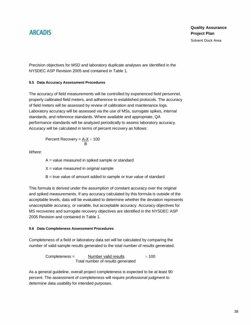
38
Quality Assurance
Project Plan
Solvent Dock Area
Precision objectives for MSD and laboratory duplicate analyses are identified in the
NYSDEC ASP Revision 2005 and contained in Table 1.
9.5 Data Accuracy Assessment Procedures
The accuracy of field measurements will be controlled by experienced field personnel,
properly calibrated field meters, and adherence to established protocols. The accuracy
of field meters will be assessed by review of calibration and maintenance logs.
Laboratory accuracy will be assessed via the use of MSs, surrogate spikes, internal
standards, and reference standards. Where available and appropriate, QA
performance standards will be analyzed periodically to assess laboratory accuracy.
Accuracy will be calculated in terms of percent recovery as follows:
Percent Recovery = A-X 100 B
Where:
A = value measured in spiked sample or standard
X = value measured in original sample
B = true value of amount added to sample or true value of standard
This formula is derived under the assumption of constant accuracy over the original
and spiked measurements. If any accuracy calculated by this formula is outside of the
acceptable levels, data will be evaluated to determine whether the deviation represents
unacceptable accuracy, or variable, but acceptable accuracy. Accuracy objectives for
MS recoveries and surrogate recovery objectives are identified in the NYSDEC ASP
2005 Revision and contained in Table 1.
9.6 Data Completeness Assessment Procedures
Completeness of a field or laboratory data set will be calculated by comparing the
number of valid sample results generated to the total number of results generated.
Completeness = Number valid results 100 Total number of results generated
As a general guideline, overall project completeness is expected to be at least 90
percent. The assessment of completeness will require professional judgment to
determine data usability for intended purposes.

39
Quality Assurance
Project Plan
Solvent Dock Area
10. Instrument/Equipment Testing, Inspection, and Maintenance Requirements
10.1 General
Testing and maintenance schedules have been developed for both field and laboratory
instruments. A summary of testing and maintenance to be performed is presented below.
10.2 Field Instruments and Equipment
Each piece of field equipment will be inspected before field sampling to confirm that it is
operational. If the equipment is not operational, it will be serviced before its use. All
equipment will be fully charged and/or have fresh batteries, as appropriate. If instrument
service is required, the appropriate task manager or field worker is responsible for
following the maintenance schedule and arranging for timely service. Field instruments
will be maintained according to their respective manufacturer’s instructions.
10.2.1 Equipment Maintenance
All measuring and test equipment to be used in support of Site activities that directly
affects the quality of the analytical data shall be subject to preventive maintenance
measures that minimize equipment downtime. Equipment will be examined to certify
that it is in operating condition, including checking the manufacturer’s operating manual
to confirm that all maintenance requirements are being observed. Field notes from
previous sampling events will be reviewed to confirm that any earlier equipment
problems have not been overlooked and that any necessary repairs to equipment have
been carried out.
Field equipment returned from a site will be inspected to confirm that it is in working
order. The inspection will be recorded in the logbook or field notebooks, as appropriate.
The last user is obligated to record any equipment problems in the logbook. Non-
operational field equipment will either be repaired or replaced. Appropriate spare parts
will be made available for field meters. Maintenance of consultant- or subcontractor-
owned or leased equipment shall be in accordance with the manufacturer’s
instructions, and all maintenance records shall be requested from the equipment
owner/leasing company and reviewed before mobilizing any equipment to the site. No
equipment shall be allowed on site if proper maintenance for that piece of equipment
has not been performed and recorded.
40
Quality Assurance
Project Plan
Solvent Dock Area
10.3 Laboratory Instruments and Equipment
10.3.1 General
Laboratory-instrument and equipment-documentation procedures include details of any
observed problems, corrective measure(s), routine maintenance, and instrument repair
(including information regarding the repair and the individual who performed the repair).
Preventive maintenance of laboratory equipment generally will follow the guidelines
recommended by the manufacturer. A malfunctioning instrument will be repaired
immediately by in-house staff or through a service call from the manufacturer.
10.3.2 Instrument Maintenance
Maintenance schedules for laboratory equipment adhere to the manufacturer’s
recommendations. Records reflect the complete history of each instrument and specify
the timeframe for future maintenance. Major repairs or maintenance procedures are
performed through service contracts with manufacturer or qualified contractors.
Paperwork associated with service calls and preventative maintenance calls will be
kept on file by the laboratory.
Laboratory-systems managers are responsible for routine maintenance of instruments
used in a particular laboratory. Any routine preventive maintenance performed is
logged into the appropriate logbooks. The frequency of routine maintenance is dictated
by the nature of samples being analyzed, the requirements of the method used, and/or
the judgment of the laboratory-systems manager. All major instruments are backed up
by comparable (if not equivalent) instrument systems in the event of unscheduled
downtime. An inventory of spare parts is also available to minimize
equipment/instrument downtime.
10.3.3 Equipment Monitoring
The operation of balances, incubators, ovens, refrigerators, and water purification
systems will be checked and documented daily. Any discrepancies will be immediately
reported to the appropriate laboratory personnel for resolution.

41
Quality Assurance
Project Plan
Solvent Dock Area
11. Instrument Calibration and Frequency
11.1 Field Instruments and Equipment
Calibration of field instruments is documented in the FSP for the applicable field
analysis method, and such procedures take precedence over the following discussion.
Field personnel are responsible for confirming that a master calibration/maintenance
log is maintained following the procedures specified for each measuring device. Where
applicable, each log will include, at a minimum, the following information:
name of device and/or instrument calibrated
device/instrument serial/identification numbers
calibration method
tolerance
calibration standard used
frequency of calibration
date(s) of calibration(s)
name of person(s) performing calibration(s)
Instruments and equipment used to gather, generate, or measure environmental data
will be calibrated at the intervals specified by the manufacturer or more frequently, and
in such a manner that accuracy and reproducibility of results are consistent with the
manufacturer’s specifications. In the event that an internally calibrated field instrument
fails to meet calibration/checkout procedures, it will be returned to the manufacturer for
service. Equipment found out of tolerance during the period of use shall be removed
from the field, and measuring and testing done with the equipment shall be addressed
via the corrective-action system described in Section 17.4 of this QAPP.
11.2 Laboratory Instrument and Equipment
Instrument calibration will follow the specifications provided by the instrument
manufacturer or specific analytical method used. Equipment calibration procedures for

42
Quality Assurance
Project Plan
Solvent Dock Area
detecting VOCs will follow guidelines presented in NYSDEC ASP 2005 Revision,
Exhibit E, Part II Section 2. When analyses are conducted according to the USEPA
SW-846 Methods and USEPA Compendium Organic Compounds in Ambient Air, the
calibration procedures and frequencies specified in the applicable method will be
followed, as noted in the attached SOPs (Attachment 1). For analyses governed by
SOPs, see the appropriate SOP for the required calibration procedures and
frequencies. Records of calibrations will be filed and maintained by the laboratory.
These records will be subject to QA audits. For all instruments, the laboratory will
maintain trained repair staff with in-house spare parts or will maintain service contracts
with vendors.
All equipment-calibration standards are traceable, directly or indirectly, to the National
Institute of Standards and Technology. All standards received shall be logged into
standard-receipt logs maintained by the individual analytical groups. Each group shall
maintain a standards-log that tracks the preparation of standards used for calibration
and QC purposes.

43
Quality Assurance
Project Plan
Solvent Dock Area
12. Inspection/Acceptance Requirements for Supplies and Consumables
All supplies to be used in the field and laboratory will be available when needed. They
will be free of target chemicals and interferences. All reagents will be tested before use
with site samples. All standards will be verified against a second source standard. The
laboratory will follow a ―first in/first out‖ procedure for the storage and use of all
consumables to minimize the risk of contamination and degradation. The various
supplies and consumables required on site are noted in the various field SOPs
included in the appropriate work plans and OMM.

44
Quality Assurance
Project Plan
Solvent Dock Area
13. Data Acquisition Requirements for Non-Direct Measurements
At present, direct use of historical data generated by outside parties is not anticipated
in completing the final deliverable. Historical data will guide the determination of
sampling locations for the deliverable. Before use, historic data sets will be reviewed
according to the procedures identified in subsequent sections of this QAPP to
determine appropriate uses of such data. The extent to which these data can be
validated will be determined by the analytical level and QC data available. Evaluation of
historic data for deliverable purposes requires:
identification of analytical levels
evaluation of QC data, when available
development of conclusions regarding the acceptability of the data for intended
uses
Acceptability of historic data for its intended uses will be determined by applying these
procedures and professional judgment. If the quality of historic data cannot be
determined, its use will be limited to general trend evaluations.

45
Quality Assurance
Project Plan
Solvent Dock Area
14. Data Management
The purpose of data management is to confirm that all necessary data are accurate
and readily accessible to meet the project’s analytical and reporting objectives. Field
investigations will include a relatively large number of samples. Thus, a structured,
comprehensive, and efficient program for data management will be necessary due to
the large amount of data that will be produced.
The project’s data-management program includes field documentation and sample
QA/QC procedures, methods for tracking and managing the data, and a system for
filing all site-related information. More specifically, data management procedures will be
used to efficiently process the information collected, such that data are readily
accessible and accurate. These procedures are detailed in the following section. The
data management plan has five elements: 1) sample-designation system, 2) field
activities, 3) sample tracking and management, 4) data-management system, and 5)
document control and inventory.
14.1 Sample Designation System
A concise and easily understandable sample-designation system is an important part of
project sampling-activities. It provides a unique sample number that will facilitate both
sample tracking and easy re-sampling of select locations to evaluate data gaps, if
necessary. The sample-designation system to be used during sampling will be
consistent, yet flexible enough to accommodate unforeseen sampling events or
conditions. A combination of letters and numbers will be used to yield a unique sample
number for each field sampled collected, as outlined in Section 6.2.1.
14.2 Field Activities
Field activities designed to gather information necessary to make decisions during
deliverable creation require consistent documentation and accurate recordkeeping.
During site activities, standardized procedures will be used to document field activities,
data security, and QA. Specific field activities are detailed as part of the project’s SOPs
(included as Attachment 2). General procedures are described in further detail in the
following subsections.

46
Quality Assurance
Project Plan
Solvent Dock Area
14.2.1 Field Documentation
Complete and accurate recordkeeping is a critical component of the field investigation.
When interpreting analytical results and identifying data trends, investigators realize
that field notes are an important part of the review and validation process. To confirm
that the field investigation is thoroughly documented, several different records, each
with its own specific reporting requirements, will be maintained, including:
field logs
COCs
instrument-calibration records
Each of these types of field documentation is described below.
Field Logs: Personnel performing field activities will keep field logs detailing all
observations and measurements made. Data will be recorded directly into site-
dedicated bound notebooks, with each entry dated and signed. To determine at any
future date that notebook pages are not missing, each page will be sequentially
numbered. Erroneous entries will be corrected by crossing out the original entry,
initialing it, and then documenting the proper information. In addition, certain media-
sampling locations will be surveyed to accurately record their locations. The survey
crew will use their own field logs and supply the sampling-location coordinates to the
database administrator.
Chain-of-Custody Forms: COCs are used to document and track sample possession
from time of collection to the time of disposal. A chain-of-custody form will accompany
each field sample collected, and one copy of the form will be filed in the field office. All
field personnel will be briefed on the proper use of the chain-of-custody procedure.
Chain-of-custody procedures and a sample form are included in all appropriate work
plans, the OMM, and required regulatory procedures.
Instrument Calibration Records: As part of data QA procedures, field monitoring and
detection equipment will be routinely calibrated. Instrument calibration confirms that
equipment used is of the proper type, range, accuracy, and precision to provide data
compatible with the specified requirements and desired results. Calibration procedures
for the various types of field instrumentation are described in Section 13.1. To

47
Quality Assurance
Project Plan
Solvent Dock Area
demonstrate that established calibration procedures have been followed, calibration
records will be prepared and maintained to include, as appropriate:
calibration date and time
equipment type and identification number
calibration frequency and acceptable tolerances
identification of individual(s) performing calibration
reference standards used
calibration data
information on calibration success or failure
The calibration record will serve as a written account of monitoring or detection
equipment QA. All erratic behavior or failures of field equipment will be subsequently
recorded in the calibration log.
14.2.2 Data Security
Measures will be taken during the field investigation to confirm that samples and
records are not lost, damaged, or altered. When not in use, all field notebooks will be
stored at the field office or locked in the field vehicle. Access to these files will be
limited to the field personnel who use them.
14.3 Sample Management and Tracking
A record of all field documentation will be maintained to confirm the validity of data
used in the site analysis. To effectively execute such documentation, specific sample
tracking and data management procedures will be used throughout the sampling
program. Sample tracking will begin with the completion of COCs, as summarized in
Section 9.2.3. The completed COCs associated with collected samples will be faxed to
the quality assurance coordinator (QAC). Copies of all completed COCs will be
maintained in the field office. The laboratory shall verify receipt of the samples
electronically (via e-mail) on the following day. When analytical data are received from
the laboratory, the QAC will review the incoming analytical data packages against the

48
Quality Assurance
Project Plan
Solvent Dock Area
information on the COCs to confirm that the correct analyses were performed for each
sample and that results for all samples submitted for analysis were received. Any
discrepancies noted will be promptly followed up by the QAC.
14.4 Data-Management System
In addition to the sample-tracking system, a data-management system will be
implemented. The central focus of the data-management system will be to develop a
personal-computer-based project database. The project database, to be maintained by
the database administrator, will combine pertinent geographical, field, and analytical
data. Information that will populate the database will be derived from three primary
sources: surveying of sampling locations, field observations, and analytical results.
Each of these sources is discussed in the following sections.
14.4.1 Computer Hardware
The database will be constructed on Pentium®-based personal-computer workstations
connected through a network server. The network will provide access to various
hardware peripherals, such as, laser printers, backup storage devices, image
scanners, and modems. Computer hardware will be upgraded to industrial and
corporate standards, as necessary, in the future.
14.4.2 Computer Software
The database will be written in Microsoft Access®, running under the Windows
®
operating system. Custom applets, such as diskette-importing programs, will be written
in either Microsoft VBA® or Microsoft Visual Basic
®. Geographic Information System
(GIS) applications will be developed in ESRI ArcGIS®, with additional customization
performed with Visual Basic®. Tables and other database reports will be generated
through Microsoft Access in conjunction with Microsoft Excel®, Microsoft Word
®, and/or
Seagate Crystal Reports®. These software products will be upgraded to current
industrial standards, as necessary.
14.4.3 Survey Information
In general, each location sampled as part of the deliverable will be surveyed to confirm
accurate documentation of sample locations for mapping and GIS purposes (if
appropriate), to facilitate the re-sampling of select sampling locations during future
monitoring programs, if needed, and for any potential remediation activities. Surveying

49
Quality Assurance
Project Plan
Solvent Dock Area
activities in the field will consist of collecting information that will be used to compute
northing and easting in-state plane-coordinates for each sampling location and the
collection of information to compute elevations relative to the National Geodetic Vertical
Datum of 1988 for select sampling locations, as appropriate. All field books associated
with surveying will be stored as a project record.
14.4.4 Field Observations
An important part of the information that will ultimately reside in the project’s data-
management system will originate in field observations. Following each sampling
event, the field personnel who performed the sampling may prepare a status
memorandum to summarize and document the event. Topics to be discussed include
the locations sampled, the sampling methodologies used, QA/QC procedures, blind
duplicate and MS/MSD sample-identification numbers, equipment-decontamination
procedures, personnel involved in the activity, and any other noteworthy aspects.
Tables are typically attached to the memorandum to summarize measurements
recorded in the field books. These tables will be developed using a personal-computer
spreadsheet program to reduce possible transcription error and facilitate transferring
information to the data-management system. For example, for sediment samples, the
table would present the sampling date and time, water depth, sediment depth, depth of
sediment recovered in a given core, the depth increment submitted for analysis, and a
description of the lithology.
Status memos are valuable tools to keep project personnel informed of the details of
field activities and are invaluable during development of the final report. Each status
memo will be reviewed for accuracy and completeness by the respective sampling-
activity manager. Following approval and finalization of each memo, the status memo
will be used to transfer field observations into the data-management system. All
pertinent field data will be manually entered into the appropriate database tables from
the COCs and field notebooks.
14.4.5 Analytical Results
The laboratory will provide analytical results both in digital and hard-copy formats. Data
packages will be examined to confirm that the correct analyses were performed for
each sample submitted and that all of the analyses requested on the chain-of-custody
form were performed. If discrepancies are noted, the QAC will be notified and will
promptly follow up with the laboratory to resolve any issues.

50
Quality Assurance
Project Plan
Solvent Dock Area
Each data package will be validated in accordance with the procedures presented in
Section 20. Data not meeting the specified standards will be flagged pending resolution
of the issue. The flag will not be removed until the issue associated with the sample
results is resolved. Although flags may remain for certain data, the use of that data may
not necessarily be restricted.
After data validation, the digital files will be used to populate the appropriate database
tables. An example of the format of the electronic data-deliverable (EDD) is included in
Table 5. This format specifies one data record for each constituent for each sample
analyzed. Specific fields include:
sample identification number
date sampled
date analyzed
parameter name
analytical result
units
detection limit
qualifier(s)
The individual EDDs, supplied by the laboratory in either an ASCII comma-separated-
value format or in a Microsoft Excel ® worksheet, will be loaded into the appropriate
database table via a custom-designed user-interface Visual Basic® program. Any
analytical data the laboratory cannot provide in electronic format will be entered
manually. After database entry, EDD data will be compared to field information
previously entered into the database to confirm that all requested analytical data have
been received.
14.4.6 Data Analysis and Reporting
The database-management system will have several functions to facilitate review and
analysis of the SRD data. Data-entry screens will be developed to assist in

51
Quality Assurance
Project Plan
Solvent Dock Area
keypunching field observations. Routines will also be developed to allow the user to
scan analytical data from a given site for a given environmental medium. Several
output functions developed by ARCADIS will be modified appropriately for use in the
data-management system.
A valuable function of the data-management system will be the capability to generate
analytical-results tables from the project databases. The system’s capacity to directly
produce tables reduces redundant manual entry of analytical results during report
preparation and precludes transcription errors. This function of the data-management
system creates a digital comma-delimited ASCII file of analytical results and qualifiers
for a given medium. The ASCII file is then processed through a spreadsheet, which
transforms the comma-delimited file into a table of rows and columns. Tables of
analytical data will be produced as part of data-interpretation tasks, data reporting, and
production of the deliverable report.
Another function of the data-management system will be to create digital files of
analytical results and qualifiers suitable for transfer to mapping/presentation software.
ARCADIS has developed a function that creates a digital file consisting of sample-
location number, state-plane coordinates, sampling date, detected constituents, and
associated concentrations and analytical qualifiers. The file is then transferred to an
AutoCAD® workstation, where another program has been developed to plot a location’s
analytical data in a "box" format at the sampling location (represented by the state-
plane coordinates). This routine greatly reduces redundant keypunching of analytical
results and facilitates efficient production of interpretative and presentation graphics.
The data-management system can also produce a digital file of select parameters that
exists in one or more of the databases. This type of custom function is accomplished
interactively and is best used to transfer select information into a number of analytical
tools, such as statistical or graphing programs.
14.5 Document Control and Inventory
ARCADIS maintains project files for this site at its Albany, New York office. Each client
project is assigned a file/job number. Each file is broken down into the following sub-files:
Agreements/Proposals (filed chronologically)
Change Orders/Purchase Orders (filed chronologically)
Invoices (filed chronologically)

52
Quality Assurance
Project Plan
Solvent Dock Area
Project Management (filed by topic)
Correspondence (filed chronologically)
Notes and Data (filed by topic)
Public Relations Information (filed by topic)
Regulatory Documents (filed chronologically)
Final Reports/Presentations (filed chronologically)
Draft Reports/Presentations (filed chronologically)
Documents Prepared by Others (filed chronologically)
Whenever possible, originals are placed in these files. These are the central files and
will serve as the site-specific files for the deliverable.

53
Quality Assurance
Project Plan
Solvent Dock Area
15. Assessment and Response Actions
15.1 General
Performance- and systems-audits will be completed in the field and laboratory during
creation of the deliverable, as described below.
15.2 Field Audits
The following field-performance- and systems-audits will be completed during this
project. The appropriate task manager will monitor field performance. Field-
performance-audit summaries will evaluate field activities to verify that they are
performed according to established protocols. The ARCADIS QAC will review field
reports and communicate concerns to the ARCADIS project manager and/or task
managers, as appropriate. In addition, the ARCADIS QAC will review the rinse and trip-
blank data to identify potential deficiencies in field sampling and cleaning procedures.
Systems audits comparing scheduled QA/QC activities associated with this document
with actual QA/QC activities completed will also be performed. The appropriate task
manager and QAC will periodically confirm that work is being performed consistent with
this QAPP, the appropriate work plan, OMM, or required regulatory procedures.
15.3 Laboratory Audits
The laboratory will perform internal audits consistent with NYSDEC ASP 2005
Revision, Exhibit E. Internal laboratory-audits are conducted by the laboratory QAC. As
part of the audit, the overall performance of laboratory staff is evaluated and compared
to performance criteria outlined in the laboratory QA manual and SOPs. Results of
these audits are summarized and issued to each department supervisor, the laboratory
manager, and the laboratory director. Each laboratory QAC will also perform a systems
audit to determine if the procedures implemented by their laboratory comply with the
QA manual and SOPs.
In addition to each laboratory’s internal audits, each laboratory (as a participant in state
and federal certification programs) is audited by representatives of the certifying
regulatory agency. Audits are usually conducted annually and focus on laboratory
conformance to the specific program-protocols for which the laboratory seeks
certification. The auditor reviews sample-handling and tracking documentation,
analytical methodologies, analytical support documentation, and final reports. The audit
findings are formally documented and submitted to the laboratory for corrective action,

54
Quality Assurance
Project Plan
Solvent Dock Area
if necessary. ARCADIS reserves the right to conduct an on-site audit of any laboratory
before the start of project analyses. Additional audits may be performed during the
course of the project, as necessary.
15.4 Corrective Action
Corrective actions are required when field or analytical data are not within the
objectives specified in this QAPP, the appropriate work plan, OMM, or required
regulatory procedures. Corrective actions include procedures to promptly investigate,
document, evaluate, and correct data collection and/or analytical procedures. Field and
laboratory corrective action procedures for the actions are described below.
15.4.1 Field Procedures
If a condition is noted in the field that could adversely affect data quality, corrective
action will be taken to prevent or mitigate this condition. Condition identification, cause,
and corrective action implemented by the field manager or their designee will be
documented on a ―Corrective Action Form‖ and reported to the appropriate ARCADIS
task manager, QAC, and project manager. Examples of such situations include:
Protocols as defined by the QAPP, appropriate work plan, OMM, or required
regulatory procedures have not been followed
Equipment not in proper working order or is not properly calibrated
QC requirements not met
Unresolved issues resulting from performance or systems audits
Project personnel will continuously monitor ongoing work performance in the course of
normal daily responsibilities.
15.4.2 Laboratory Procedures
In the laboratory, when a condition is noted to adversely affect data quality, corrective
action will be taken to prevent or mitigate this condition. Condition identification, cause,
and corrective action taken will be documented and reported to the appropriate project
manager and QAC. Corrective action may be initiated, at a minimum, under the
following conditions:

55
Quality Assurance
Project Plan
Solvent Dock Area
Specific laboratory analytical protocols have not been followed
Protocols as defined by this QAPP have not been followed
Pre-determined data-acceptance standards are not obtained
Equipment is not in proper working order or calibrated
Sample and test results are not completely traceable
QC requirements have not been met
Unresolved issues resulting from performance or systems audits
Laboratory personnel will continuously monitor ongoing work performance in the
normal course of daily responsibilities. Corrective action begins when the problem is
identified. At whatever level this occurs (analyst, supervisor, data review, or QC), the
issue is brought to the attention of the laboratory QAC and, ultimately, the laboratory
director. Final approval of any action deemed necessary is subject to the approval of
the laboratory director. Any corrective action deemed necessary would be
implemented, based on system or performance audits or the results of data review.
The corrective action may include sample re-extraction, re-preparation, re-analysis,
cleanup, dilutions, matrix modifications, or other activities.
16. Reports to Management
16.1 Internal Reporting
The analytical laboratory will submit analytical reports to ARCADIS for review. If
required, ARCADIS will, in turn, submit the reports to the data validator for review.
Supporting data (i.e., historic data, related field or laboratory data) will also be reviewed
to evaluate data quality, as appropriate. The ARCADIS QA manager will incorporate
results of data validation reports and assessments of data usability into a summary
report (if required) that will be submitted to the ARCADIS project manager and
appropriate task managers. If required, this report will be filed in the project file at
ARCADIS’ Albany, New York office and will include the following:
Assessment of data accuracy, precision, and completeness for both field and
laboratory data

56
Quality Assurance
Project Plan
Solvent Dock Area
Results of the performance and systems audits
Significant QA/QC problems, solutions, corrections, and potential
consequences
Analytical data validation report
16.2 Supplemental Remedial Design Reporting
As samples are transported to the laboratory, a copy of the chain-of-custody form will
be forwarded to the ARCADIS project manager. Upon receipt of the ―ASP— Category
B Data Package‖ from the laboratory, the ARCADIS QA manager will determine if the
data package has met the required DQOs. The analytical data package will be
submitted to the ARCADIS project manager and the analytical data will be incorporated
into the final deliverable report in a tabulated format.

57
Quality Assurance
Project Plan
Solvent Dock Area
17. Data Reduction and Review
17.1 General
After field and laboratory data are obtained, the data will be subjected to the following:
reduction, or manipulation mathematically, or otherwise into meaningful and
useful forms
review
organization, interpretation, and reporting
data validation
17.2 Field Data Reduction and Review
17.2.1 Field Data Reduction
Information collected in the field through visual observation, manual measurement,
and/or field instrumentation will be recorded in field notebooks or data sheets, and/or on
forms. Such data will be reviewed by the appropriate task manager for adherence to the
appropriate work plan, OMM, or required regulatory procedures and this QAPP for
consistency. Concerns identified through this review will be discussed with the field
personnel, corrected if possible, and, as necessary, incorporated into data evaluation.
17.2.2 Field Data Review
Field-data calculations, transfers, and interpretations will be conducted by field
personnel and reviewed for accuracy by the appropriate task manager and the QAC.
Logs and documents will be checked for:
general completeness
readability
usage of appropriate procedures
appropriate instrument calibration and maintenance

58
Quality Assurance
Project Plan
Solvent Dock Area
reasonableness in comparison to present and past data collected
correct sample locations
correct calculations and interpretations
17.3 Laboratory Data-Reduction and Review
17.3.1 Laboratory Data-Reduction
Data-reduction calculations will be specified in each of the analytical methods
referenced previously. Whenever possible, analytical data will be transferred directly
from the instrument to a computerized data-system. Raw data will be entered into
permanently bound laboratory notebooks. The data entered must be sufficient to
document all factors used to arrive at the reported value. Concentration calculations for
chromatographic analyses will be based on response factors. Quantitation will be
performed using either internal or external standards.
Inorganic analyses will be based on regression analysis. Regression analysis is used
to fit a curve through the calibration-standard data. Sample concentrations will be
calculated using the resulting regression-equations. Nonaqueous values will be
reported on a dry-weight basis. Unless otherwise specified, all values will be reported
uncorrected for blank contamination.
17.3.2 Laboratory Data Review
Data will be subjected to multi-level review by the laboratory. The group leader will
review all data reports before release for the final data report and signature by the
laboratory project manager. The laboratory QAC will review a cross-section of the final
data reports before shipment to ARCADIS.
Corrective action will be taken if discrepancies or deficiencies exist in the analytical
results, as discussed in Section 17.4. Deficiencies discovered as a result of internal
data-review, as well as the corrective actions to be used to rectify the situation, will be
documented on a ―Corrective Action Form.‖ This form will be submitted to the
ARCADIS project manager.

59
Quality Assurance
Project Plan
Solvent Dock Area
17.4 Data Validation and Verification
All data generated for health and safety and engineering/design-control purposes will
be subjected to the data validation and verification procedures outlined in Section 18.
Data generated for disposal purposes will not be reviewed.

60
Quality Assurance
Project Plan
Solvent Dock Area
18. Data Validation and Verification
Data validation entails a review of the QC data and the raw data to verify that the
laboratory was operating within required limits, the analytical results were correctly
transcribed from the instrument read-outs, and which, if any, environmental samples
were related to any out-of-control QC samples. The objective of data validation is to
identify any questionable or invalid laboratory measurements. ARCADIS will validate all
data generated producing a NYSDEC Data Usability Summary Report for each
individual SDG using the most recent versions of the USEPA’s Function Guidelines
(USEPA, 1999b) and USEPA Region II SOPs for data validation available when the
project began, where appropriate. These procedures and criteria may be modified, as
necessary, to address project-specific and method-specific criteria, control limits, and
procedures. Data validation will consist of data screening, checking, reviewing, editing,
and interpretation to document analytical data quality and to determine whether the
quality is sufficient to meet the DQOs.
The data validator will verify that reduction of laboratory measurements and laboratory
reporting of analytical parameters is in accordance with the procedures specified for
each analytical method and/or as specified in this QAPP. Any deviations from the
analytical method or any special reporting requirements apart from what is specified in
this QAPP will be detailed on COCs. Upon receipt of laboratory data, the data validator
will execute the following procedures:
Evaluate completeness of the data package
Verify that field COCs were completed and that samples were handled
properly
Verify that holding times were met for each parameter. Holding-time
exceedences, should they occur, will be documented. Data for all samples
exceeding holding time requirements will be flagged as either estimated or
rejected. The decision as to which qualifier is more appropriate will be made on
a case-by-case basis
Verify that parameters were analyzed according to the methods specified
Review QA/QC data (i.e., make sure duplicates, blanks, and spikes were
analyzed on the required number of samples, as specified in the method; verify
that duplicate and MS recoveries are acceptable)

61
Quality Assurance
Project Plan
Solvent Dock Area
Investigate anomalies identified during review. When anomalies are identified,
they will be discussed with the project manager and/or laboratory manager, as
appropriate
If data appear suspect, investigate the specific data of concern. Calculations
will be traced back to raw data; if calculations do not agree, the cause will be
determined and corrected
Deficiencies discovered through the data review, as well as corrective actions
implemented in response, will be documented and submitted as a written report
addressing the following topics (as applicable to each method):
data-package assessment
description of any protocol deviations
failures to reconcile reported and/or raw data
assessment of any compromised data
overall appraisal of the analytical data
table of site name, sample quantities, matrix, and fractions analyzed
Note that qualified results do not necessarily invalidate data. The goal to produce the
best possible data does not necessarily mean producing data without QC qualifiers.
Qualified data can provide useful information. Resolution of any issues regarding
laboratory performance or deliverables will be handled between the laboratory and the
data validator. The ARCADIS QAC may make suggestions for re-analysis at this point.
Data validation reports will be kept in the project file at the ARCADIS office in Albany,
New York.

62
Quality Assurance
Project Plan
Solvent Dock Area
19. Reconciliation with User Requirements
Data results will be examined to determine the performance achieved for each data-
usability criterion. Performance will then be compared with project objectives and
DQOs. Deviations from objectives will be noted. Additional action may be warranted
when performance does not meet objectives for critical data. Options for corrective
action relating to incomplete information, questionable results, or inconsistent data may
include any or all of the following:
retrieval of missing information
request for additional explanation or clarification
re-analysis of sample from extract (when appropriate)
re-calculation or re-interpretation of results by the laboratory
These actions may improve data quality, reduce uncertainty, and may eliminate the
need to qualify or reject data. If these actions do not improve data quality to an
acceptable level, the following additional actions may be taken:
extrapolation of missing data from existing data points
use of historical data
evaluation of the critical/non-critical nature of the sample
If the data gap cannot be resolved by these actions, an evaluation of the data bias and
potential for false negatives and positives can be performed. If the resultant uncertainty
level is unacceptable, additional samples must be collected and analyzed.

63
Quality Assurance
Project Plan
Solvent Dock Area
20. References
ARCADIS. 2008. Solvent Dock Area and West Lot Site Health and Safety Plan.
November.
ARCADIS. 2009a. Groundwater Collection and Treatment System Operation,
Maintenance and Monitoring Manual. October 2009.
ARCADIS. 2009b. Monitored Natural Attenuation Plan. October 2009.
ARCADIS. 2009c. Sub-Slab Depressurization System Operation, Maintenance and
Monitoring Plan. October 2009.
ARCADIS 2009d. Work Plan for Supplemental Investigation. October 2009.
Blasland, Bouck & Lee, Inc. (BBL). 1995a. French Road Facility Ground-Water
Collection and Treatment System. October.
BBL. 1995b. Ground-Water Collection And Treatment System, Supplemental
Information, November.
BBL. 1995c. Phase I Environmental Site Assessment, French Road Facility, October.
BBL. 1995d. Storm-Sewer Basis-of-Design Report.
BBL. 1995e. Storm-Sewer Investigation Report. May.
BBL. 1998a. Former LMC French Road Facility, Monitoring Well 7 Analytical Results,
April.
New York State Department of Environmental Conservation. 2002. Draft DER-10
Technical Guidance for Investigation and Remediation. December 2002.
New York State Department of Environmental Conservation. 2008. Order on Consent
Index Number CO 6-20080321-5. October 3.
United States Environmental Protection Agency. 2006. Guidance on Systematic
Planning Using the Data Quality Objectives Process. EPA-QA/G-4. Office of
Environmental Information. February, 2006.

64
Quality Assurance
Project Plan
Solvent Dock Area
United States Environmental Protection Agency. 2002a. Contract Laboratory Program
National Functional Guidelines for Inorganic Data Review. EPA-540/R-01-008
July 2002.
United States Environmental Protection Agency. 2002b. Guidance for Quality
Assurance Project Plans. EPA-QA/G-5. Office of Environmental Information.
December 2002.
United States Environmental Protection Agency. 2001. EPA Requirements for Quality
Assurance Project Plans for Environmental Operations. EPA-QA/R-5. Office of
Environmental Information. March 2001.
United States Environmental Protection Agency. 1999a. Compendium of Methods for
the Determination of Organic Compounds in Ambient Air. January 1999.
United States Environmental Protection Agency. 1999b. Contract Laboratory Program
National Functional Guidelines for Organic Data Review. EPA-540/R-99-008
October 1999.
United States Environmental Protection Agency. 1996. Test Methods for Evaluating
Solid Waste. SW-846 3rd Edition, Update 3. Office of Solid Waste December
1996.
United States Environmental Protection Agency. Contract-Laboratory Program National
Functional Guidelines for Inorganic Data Review. EPA-540/R-94-013.
February 1994.
United States Environmental Protection Agency. 1992. Guide to Management of
Investigation-Derived Wastes. 9345.3-03FS. January 1992.
United States Environmental Protection Agency. 1991. NEIC Policies and Procedures
Manual. EPA-330/9-78-001R. National Enforcement Investigations Center.
May 1978, Revised August 1991.
United States Environmental Protection Agency. 1980. Interim Guidance and
Specifications for Preparing Quality Assurance Project Plans. QAMS-005/80.
Office of Research and Development. December 1980.

Figures

ARCADIS
Donald Sauda
Project Director
Lockheed Martin
Corporation
Thomas Blackman
Program Lead
ARCADIS
Mary Ann Doyle
Data Validation
ARCADIS
Katie Arnold
Scientist
Figure 1. Utica Organizational Chart
ARCADIS
Sarah Medearis
Project Advisor
ARCADIS
Christopher Motta
Project Manager
ARCADIS
Greg Ertel
Health & Safety
ARCADIS
Jeffrey Bonsteel
Task Manager
ARCADIS
Todd Carignan
Engineer
NYSDEC
Larry Rosenmann
Project Manager
TestAmerica Laboratories
Candace Fox
Client Contact
Centek Laboratories
Russell Pellegrino
Client Contact
NYSDOH
Greg Rys
Project Manager

PROJECT MANAGER
CHECKED BY
DATE DRAWN FIGURE NUMBER
PROJECT NUMBER
DRAWING NUMBER
Site Location Map
Solvent Dock Area
UTICA, NEW YORK
C. Motta
J. Bonsteel
April 5, 2005
N
2
Source: USGS, 1955
Scale: 1:24000
NJ000630.0001
Site

Tables

Table 1. Analytical Quality Control Limits, Quality Assurance Project Plan, Lockheed Martin Corporation, Utica, New York
Parameter Surrogate MS/MSD LCS MS/MSD
Lab
Duplicate
Field
Duplicate
Volatile Organics 60-140 60-140 70-140 25 -- 50
Volatile Organics 60-140 60-140 70-140 25 -- 100
VOCs TO-15 -- -- 70-130 -- 20 100
Notes:1 The listed QC limits are based on SW-846 guidance and are advisory. The actual limits are determined based on
laboratory performance. Frequent failure to meet the QC limits; however, warrant investigation of the laboratory.
QC - quality control
MS/MSD - matrix spike/matrix spike duplicate
RPD - relative percent difference
LCS - laboratory control sample
Air
Accuracy - % Recovery Precision - RPD
Water
Soil
G:\APROJECT\LOCKHEED\Utica\Reports\Solvent Dock\QAPP\Revised August 2009\DRAFT FINAL QAPPDEC\Tables\LMCuticaQAPPTABLES.xlsPage 1 of 1

Table 2. Sample Containers, Preservation, and Holding Times, Quality Assurance Project Plan, Lockheed Martin Corporation, Utica, New York
Parameter Method1
Bottle Type Preservation Holding Time2
Water / Soil
Volatile Organic Compounds 8260 Two 40 mL glass vials with Teflon®-lined lid Cool to 4°C pH<2 48 hours to preservation
Air
Volatile Organic Compounds TO-15 1 - Canister None 10 days to analysis
Notes:1 USEPA. Office of Solid Waste and Emergency Response. Test Methods for Evaluating Solid Waste. SW-846 3rd ed. Washington, D.C. 1996.
2 All holding times are calculated from verified time of sample receipt and will be consistent with Exhibit I of the NYSDEC Analytical Services Protocol
mL - milliliters
oz - ounceoC - degrees Celsius
G:\APROJECT\LOCKHEED\Utica\Reports\Solvent Dock\QAPP\Revised August 2009\DRAFT FINAL QAPPDEC\Tables\LMCuticaQAPPTABLES.xls 1 of 1

Table 3. Environmental and Quality Control Analyses, Quality Assurance Project Plan, Lockheed Martin Corporation, Utica, New York
Freq. No. Freq. No. Freq. No. Freq. No. Freq. No. Freq. No.
Volatile Organic Compounds (SW-846 8260) 1 1/cooler 1 1/20 1 1/20 1 1/20 1 1/20 1 NA -- 6
Volatile Organic Compounds (TO-15) 1 NA -- NA -- 1/20 1 NA -- NA -- NA -- 2
Volatile Organic Compounds (SW-846 8260) 1 1/cooler 1 1/20 1 1/20 1 1/20 1 1/20 1 NA -- 6
Sample counts are an approximation of the estimated minimal quantity. Additional samples may be obtained based on analytical data and result in increased QC samples. 1 -
2 -
1/day - One rinse blank per day or one per 20 samples, whichever is more frequent. Rinse blanks not required when dedicated sampling equipment or new, clean, unused disposable sampling equipment is used.
Freq. - frequency
NA - not applicable
No. - number
QC - quality control
TBD - to be determined
TCL - Target Compound List
TAL - Target Analyte List
Trip Blank Matrix Spike Matrix Spike Duplicate Lab DuplicateRinse Blank Field Duplicate
Soil Sampling
Groundwater Sampling
Vapor Sampling
Field QC AnalysesEstimated
Environmental
Sample Quantity
Parameter Total
Laboratory QC Sample
G:\APROJECT\LOCKHEED\Utica\Reports\Solvent Dock\QAPP\Revised August 2009\DRAFT FINAL QAPPDEC\Tables\LMCuticaQAPPTABLES.xlsPage 1 of 1

Table 4. Parameters, Methods, and Target Reporting Limits, Quality Assurance Project Plan, Lockheed Martin Corporation, Utica,
New York
NYS GW Laboratory Laboratory
Analyte STD./G.V.3
MDL RL
Volatile Organic Compounds 8260 1
Dichlorodifluoromethane 5 0.29 1.0
Chloromethane 5 0.35 1.0
Bromomethane 5 0.28 1.0
Vinyl chloride 2 0.24 1.0
Chloroethane 5 0.32 1.0
Trichlorofluoromethane 5 0.15 1.0
Methylene chloride 5 0.44 1.0
1,1,2-Trichloro-1,2,2-trifluoroethane 5 0.21 1.0
Acetone 50 1.30 5
Carbon disulfide 60 0.19 1.0
Methyl acetate NA 0.50 1.0
1,1-Dichloroethene 5 0.29 1.0
1,1-Dichloroethane 5 0.38 1.0
trans-1,2-Dichloroethene 5 0.42 1.0
Chloroform 7 0.34 1.0
1,2-Dichloroethane 0.6 0.21 1.0
cis-1,2-Dichloroethene 5 0.38 1.0
2-Butanone 50 1.30 5
1,1,1-Trichloroethane 5 0.26 1.0
Cyclohexane NA 0.53 1.0
Carbon tetrachloride 5 0.27 1.0
Bromodichloromethane 50 0.39 1.0
1,2-Dichloropropane 1 0.32 1.0
cis-1,3-Dichloropropene 0.4 0.36 1.0
Trichloroethene 5 0.46 1.0
Methylcyclohexane NA 0.50 1.0
Dibromochloromethane 50 0.39 1.0
1,2-Dibromoethane 0.0006 0.17 1.0
1,1,2-Trichloroethane 1 0.21 1.0
Benzene 1 0.41 1.0
trans-1,3-Dichloropropene 0.4 0.37 1.0
Bromoform 50 0.26 1.0
Isopropylbenzene 5 0.19 1.0
4-Methyl-2-pentanone NA 0.91 5.0
2-Hexanone 50 1.20 5.0
Tetrachloroethene 5 0.36 1.0
Toluene 5 0.51 1.0
1,1,2,2-Tetrachloroethane 5 0.21 1.0
Chlorobenzene 5 0.32 1.0
Water (µg/L)
G:\APROJECT\LOCKHEED\Utica\Reports\Solvent Dock\QAPP\Revised August 2009\DRAFT FINAL QAPPDEC\Tables\LMCuticaQAPPTABLES.xls Page 1 of 4

Table 4. Parameters, Methods, and Target Reporting Limits, Quality Assurance Project Plan, Lockheed Martin Corporation, Utica,
New York
NYS GW Laboratory Laboratory
Analyte STD./G.V.3
MDL RL
Volatile Organic Compounds 8260 1
Ethylbenzene 5 0.18 1.0
Styrene 5 0.18 1.0
Xylenes (total) 5 0.66 2.0
1,3-Dichlorobenzene 3 0.36 1.0
1,4-Dichlorobenzene 3 0.39 1.0
1,2-Dichlorobenzene 3 0.36 1.0
1,2-Dibromo-3-chloropropane 0.04 0.39 1.0
1,2,4-Trichlorobenzene 5 0.41 1.0
Methyl t-butyl ether (MTBE) 10 0.16 1.0
Notes:1 USEPA. Office of Solid Waste and Emergency Response. Test Methods for
Evaluating Solid Waste SW-846 3rd ed.Washington, D.C. 1996.2 The target reporting limits are based on wet weight. The actual reporting limits will
vary based on sample weight and moisture content.3 Water guidance values (GV) are as presented in the NYSDEC, Division of Water,
Technical and Operation Guidance Series (TOGS) document etitled, Ambient Water
Quality Standards and Guidance Values and Groundwater Effluent Limitations
(TOGS 1.1.1), dated June 1998, last revised April 2000.4 Soil guidance values (GV) are as presented in the NYSDEC Technical and
Administrative Guidance Memorandum (TAGM) etitled, Determination of Soil
Cleanup Objectives and Cleanup Levels, HWR-94-4046 (TAGM 4046) dated
January 24, 1994.
µg/L - micrograms per liter
µg/kg - micrograms per kilogram
MDL - method detection limit
Water (µg/L)
G:\APROJECT\LOCKHEED\Utica\Reports\Solvent Dock\QAPP\Revised August 2009\DRAFT FINAL QAPPDEC\Tables\LMCuticaQAPPTABLES.xls Page 2 of 4

Table 4. Parameters, Methods, and Target Reporting Limits, Quality Assurance Project Plan, Lockheed Martin Corporation, Utica,
New York
Guidance Laboratory Laboratory
Analyte Criteria1
MDL RL
Volatile Organic Compounds TO-15
1,1,1-Trichloroethane - 0.013 0.50
1,1,2,2-Tetrachloroethane - 0.023 0.50
Freon-113 - 0.015 0.50
1,1,2-Trichloroethane - 0.017 0.50
1,1-Dichloroethane - 0.026 0.50
1,1-Dichloroethene - 0.028 0.50
1,2,4-Trichlorobenzene - 0.046 0.50
1,2,4-Trimethylbenzene - 0.013 0.50
1,2-Dibromoethane - 0.024 0.50
1,2-Dichlorobenzene - 0.025 0.50
Dichlorodifluoromethane - 0.015 0.50
1,2-Dichloroethane - 0.021 0.50
1,2-Dichloropropane - 0.019 0.50
1,3,S-Trimethylbenzene - 0.015 0.50
1,3-Butadiene - 0.029 0.50
1,3-Dichlorobenzene - 0.03 0.50
1,4-Dichlorobenzene - 0.024 0.50
4-Ethyltoluene - 0.021 0.50
Acetone - 0.5 1.00
Benzene - 0.013 0.50
Benzyl Chloride - 0.031 0.50
Bromodichloromethane - 0.015 0.50
Bromoform - 0.021 0.50
Bromomethane - 0.025 0.50
Carbon Disulfide - 0.01 0.50
Carbon Tetrachloride - 0.017 0.50
Chlorobenzene - 0.013 0.50
Chloroethane - 0.032 0.50
Chloroform - 0.025 0.50
Chloromethane - 0.015 0.50
CIS-1,2-Dichloroethene - 0.0 0.50
CIS-1,3-Dichloropropene - 0.015 0.50
Cyclohexane - 0.028 0.50
Dibromochloromethane - 0.015 0.50
Freon-114 - 0.013 0.50
Ethyl Acetate - 0.057 0.50
Ethylbenzene - 0.0 0.50
Air (ppbv)
G:\APROJECT\LOCKHEED\Utica\Reports\Solvent Dock\QAPP\Revised August 2009\DRAFT FINAL QAPPDEC\Tables\LMCuticaQAPPTABLES.xls Page 3 of 4

Table 4. Parameters, Methods, and Target Reporting Limits, Quality Assurance Project Plan, Lockheed Martin Corporation, Utica,
New York
Guidance Laboratory Laboratory
Analyte Criteria1
MDL RL
Heptane - 0.015 0.50
Hexachlorobutadiene - 0.029 0.50
Hexane - 0.021 0.50
M+P-Xylene - 0.01 1.00
2-Hexanone - 0.061 0.50
2-Butanone - 0.06 0.50
4-Methyl-2-Pentanone - 0.056 0.50
Methyl Tert-Butyl Ether - 0.015 0.50
Methylene Chloride - 0.024 0.50
O-Xylene - 0.01 0.50
Propylene - 0.027 0.50
Styrene - 0.017 0.50
Tetrachloroethene - 0.019 0.50
Tetrahydrofuran - 0.033 0.50
Toluene - 0.01 0.50
Trans-1,2-Dichloroethene - 0.01 0.50
Trans-1,3-Dichloropropene - 0.015 0.50
Trichloroethene - 0.028 0.50
Trichlorofluoromethane - 0.01 0.50
Vinyl Acetate - 0.15 0.50
Vinyl Chloride - 0.03 0.50
Notes:
NA - not applicable
ppbv - parts per billion by volume.
1 NYSDOH Guidance for Soil Vapor Intrusion will be used for evaluation of all soil
Air (ppbv)
G:\APROJECT\LOCKHEED\Utica\Reports\Solvent Dock\QAPP\Revised August 2009\DRAFT FINAL QAPPDEC\Tables\LMCuticaQAPPTABLES.xls Page 4 of 4

Table 5. Electronic Data Deliverable (EDD) Format, Quality Assurance Project Plan, Lockheed Martin Corporation, Utica, New York
Field Name (1)
Data Type (2)
Notes
Sample Name Text-50 Sample ID as it appears on Laboratory Form 1 for analysis (e.g., MW-1 reported as MW-1RE for re-analysis).
COC Sample Name Text-50 Sample ID as it appears on the chain of custody.
SDG Text-50 Sample Delivery Group
Lab Sample ID Text-50
Matrix Text-25 e.g., Soil, Water, Sediment
Sample Type Text-10
e.g., FB, RB, FD , FS, TB, MS, MSD -- for Field Blank, Rinse Blank, Field Duplicate, Field Sample, Trip Blank, Matrix
spike, Matrix Spike Duplicate respectively. MS and MSD sample results are optional.
Date Collected Date/Time
Time Collected Date/Time
Depth Start Number
Depth End Number
Depth Units Text-25
Method Text-50
Analytical method used by laboratory. Include "-TCLP" or "-Filtered" as appropriate (e.g., Soil-1 reported as Soil-1-
TCLP for TCLP samples).
CAS Number Text-25 Chemical Abstracts Service Registry Number
Analyte Text-100
Result Value Number For non-detected results a "U" must be present in Lab Qualifiers field.
Lab Qualifiers Text-10 "U" for not detected, others as defined by the lab.
Reporting Limit Number PQL
Result Units Text-25
Dilution Factor Number
Reportable Result Yes/No
If the field is not included, default on import will be "Yes". If the field is included it must be populated. Used where re-
analyses or dilutions are present to determine proper result to report.
Filtered Yes/No
MDL Number Method Detection Limit
Date Analyzed Date/Time
Time Analyzed Date/Time
Date Received Date/Time Date Received by Lab
Laboratory Text-50
Lab Certification Number Text-50
Result Type Text-10
e.g., IS, SC, SUR, TIC or TRG -- for Internal Standard, Spiked Compound, Surrogate, Tentatively Identified
Compound, Target (regular) result, respectively. IS, SC and SUR results are optional.
Basis Text-10 e.g., Wet, Dry or NA -- for wet weight, dry weight, not applicable, respectively.
Test Type Text-10
e.g., Initial, DL, DL1…DLn, RE, RE1…Ren, REX, REX1…REXn; where Initial = Initial Analysis, DL = Dilution, RE =
Re-analysis, REX = Re-extraction, n = the nth analysis of the test type.
Time Received Date/Time Time Received by Lab
Notes:
1. Fields highlighted in pink are not required. They may be left empty or the field can be eliminated from the EDD if the lab is not providing that data.
2. Number after "Text-" indicates the maximum number of characters allowed.
3. If lab is providing Matrix or Sample Types, they can use codes different from the examples above but will need to provide definitions for them.
4. Depth related fields can be left blank for samples where they are not applicable.
G:\APROJECT\LOCKHEED\Utica\Reports\Solvent Dock\QAPP\Revised August 2009\DRAFT FINAL QAPPDEC\Tables\LMCuticaQAPPTABLES.xls 1 of 1

Appendix A
Sample Chain-of-Custody Form

CHAIN OF CUSTODY & LABORATORYANALYSIS REQUEST FORM Page ___ of ___
Lab Work Order #ID#:
Preservative
Filtered ()
# of Containers
Container Information
PARAMETER ANALYSIS & METHOD
Collection Type ()Matrix
Date Time Comp GrabSample ID
Project Name/Location (City, State):
Sampler’s Printed Name:
Project #:
Sampler’s Signature:
Contact & Company Name:
Address:
City State Zip
Telephone:
Fax:
E-mail Address:
Special Instructions/Comments: Special QA/QC Instructions():
REMARKS
Laboratory Information and Receipt Relinquished By Received By Relinquished By Laboratory Received ByLab Name:
Cooler packed with ice ()
Specify Turnaround Requirements:
Shipping Tracking #:
Cooler Custody Seal ()
Intact Not Intact
Sample Receipt:
Condition/Cooler Temp: _________
Printed Name:
Firm:
Date/Time:
Signature:
Printed Name:
Firm/Courier:
Date/Time:
Signature:
Printed Name:
Firm/Courier:
Date/Time:
Signature:
Printed Name:
Firm:
Date/Time:
Signature:
20730826 CofC AR Form 01.12.2007 Distribution: WHITE – Laboratory returns with results YELLOW – Lab copy PINK – Retained by ARCADIS
KeysPreservation Key:A. H2SO4B. HCLC. HNO3D. NaOHE. NoneF. Other: ________
G. Other: ________
H. Other: ________
Container Information Key:1. 40 ml Vial2. 1 L Amber3. 250 ml Plastic4. 500 ml Plastic5. Encore6. 2 oz. Glass7. 4 oz. Glass8. 8 oz. Glass9. Other: ________
10. Other: ________Matrix Key:SO - SoilW - WaterT - Tissue
SE - SedimentSL - SludgeA - Air
NL - NAPL/OilSW - Sample WipeOther: _______
Send
Res
ults
to:

Attachment 1
Laboratory Standard Operating
Procedures


Centek Laboratories, LLC. Laboratory Quality Manual 143 Midler Park Drive Doc. LQM-3 Rev. No. 4 Syracuse, New York 13206 Date: 4/22/09 Page 1 of 27
Controlled Copy on Goldenrod Paper, Do Not Duplicate
NY Laboratory ID #11830 Laboratory Quality Manual Russell J. Pellegrino, Jr. (315) 431-9730 Approved : _______________________________________________ Laboratory Director Name Approved : _______________________________________________ Quality Assurance Officer Name Distribution List: Russell Pellegrino, Laboratory Director Russell J. Pellegrino, Jr., Laboratory Manager Michael S. Palmer, QA Deputy Officer Organics Office

Centek Laboratories, LLC. Laboratory Quality Manual 143 Midler Park Drive Doc. LQM-3 Rev. No. 4 Syracuse, New York 13206 Date: 4/22/09 Page 2 of 27
Controlled Copy on Goldenrod Paper, Do Not Duplicate
Revision Record Revision Date Person Description of Number Responsible Change 1 9/28/03 MA Winslow Initial Release 1A 11/25/03 MA Winslow Director/Manager Change 2 5/5/2004 MA Winslow Director/Manager Change/NYDOH ID# 3 3/17/06 M. Palmer QC Officer/Annual /Audit Updates 4 4/22/09 M. Palmer QC Deputy Officer/Annual /Audit Updates The following laboratory staff members have read this manual. A copy of this page will be distributed to the employee training record file. ______________________________ _____________ ______ Name Title Date ______________________________ _____________ ______ Name Title Date ______________________________ _____________ ______ Name Title Date ______________________________ _____________ ______ Name Title Date ______________________________ _____________ ______ Name Title Date

Centek Laboratories, LLC. Laboratory Quality Manual 143 Midler Park Drive Doc. LQM-3 Rev. No. 4 Syracuse, New York 13206 Date: 4/22/09 Page 3 of 27
Controlled Copy on Goldenrod Paper, Do Not Duplicate
Table of Contents
Page No. 1. Quality Policy 4 2. Accredited Test Methods 5 3. Organization Chart 6 4. Relationship Between Management, Technical Operations,
Support Services and the Quality System 7 5. Job Descriptions of Staff 7
A. Deputy List in Case of Absence 8 6. Document Control 9 7. Traceability of Measurements 9 8. Review of All New Work 10 9. Calibration/Verification of Test Procedures 10 10. Sample Handling 10
A. Sample Acceptance Policy 10 B. Sample Receipt Protocol 11 C. Procedures for Handling Submitted Samples 12
11. Laboratory Environment 12 12. Procedures for Calibration, Verification and Maintenance of Equipment 13 13. Proficiency Testing Participation and Use of Reference Materials 13 14. Internal Quality Control Measures 13 15. Testing Discrepancies 14 16. Preventative/Corrective Action Procedures
15 17. Permitted Departures from Standard Specifications or Documented
Policies and Procedures 15 18. Complaints 15 19. Internal Audit and Data Review 16
A. Data Review 16 B. Internal Quality System Audits 16 C. Managerial Review 16
20. Training and Review of Personnel Qualifications 17 21. Education and Training in Ethical and Legal Responsibilities Including
the Potential Punishments and Penalties for Improper, Unethical or Illegal Actions 18
22. Reporting Analytical Results 18 23. Reagents and Standards 18

Centek Laboratories, LLC. Laboratory Quality Manual 143 Midler Park Drive Doc. LQM-3 Rev. No. 4 Syracuse, New York 13206 Date: 4/22/09 Page 4 of 27
Controlled Copy on Goldenrod Paper, Do Not Duplicate
1. Quality Policy It is the laboratory’s objective to provide technically valid laboratory test results that accurately and precisely represent the quality of a client’s sample being analyzed. The laboratory management is committed to comply with ISO 17025,NELAP and AIHA’s International Standard and to continually improve the effectiveness of the management system. Top management shall provide evidence of commitment to the development and implementation of the management system and continually improving its effectiveness. The Laboratory Quality Manual shall be updated whenever necessary and shall be reviewed and approved by management at least annually. All Documents issued to personnel in the laboratory as part of the management system shall be reviewed and approved use by authorized personnel prior to issue. A master list or an equivalent document control procedure identifying the current revision status and the distribution of documents in the management system shall be established and be readily available to preclude the use of invalid and/or obsolete documents. The procedure(s) adopted shall ensure that: documents are periodically reviewed and, where necessary, revised to ensure continuing suitability and compliance with applicable requirements. Management system documents generated by the laboratory shall be uniquely identified. Such identification shall include the date of issue and/or revision identification, page numbering, the total number of pages or a mark to signify the end of the document and the issuing authority(ies). Centek will always strive to perform laboratory work that is in conformance to the NELAC, ISO/IEC 17025 AND AIHA LABORATORY QUALITY ASSURANCE PRGRAM POLICY DOCUMENT standards, resulting in the overall improvement of the laboratory’s quality over time. Demonstration of the laboratory’s commitment to reach its goal will result in the following:
• Adequately staffed and equipped facility • Successful participation when available in the proficiency testing programs
operated by the New York State Environmental Laboratory Approval Program, AIAH, the National Institute for Occupational Safety and Health and the US Environmental Protection Agency.
• Successful implementation of a NELAC, ISO/IEC 17025 AND AIHA LABORATORY QUALITY ASSURANCE PRGRAM POLICY DOCUMENT compliant quality system
• Annual internal audits (using both the NELAC and AIHA Checklists – 2 individual audits) with management review and yearly review for updating and maintenance of the/this Laboratory Quality Manual and all SOPs
• Successful biennial assessments by the New York State Environmental Laboratory Approval Program
• Timely reporting of laboratory test results to the regulating authorities • Laboratory test results that are supported by quality control data and
documented laboratory testing procedures

Centek Laboratories, LLC. Laboratory Quality Manual 143 Midler Park Drive Doc. LQM-3 Rev. No. 4 Syracuse, New York 13206 Date: 4/22/09 Page 5 of 27
Controlled Copy on Goldenrod Paper, Do Not Duplicate
A copy of the quality policy is given to employees during the training of new hires. It is understood, implemented and maintained by employees at all levels. This is documented by management through the employee evaluation process, the training procedure, the internal audit process and the document control process.

Centek Laboratories, LLC. Laboratory Quality Manual 143 Midler Park Drive Doc. LQM-3 Rev. No. 4 Syracuse, New York 13206 Date: 4/22/09 Page 6 of 27
Controlled Copy on Goldenrod Paper, Do Not Duplicate
2. Accredited Test Methods
Test Method Reference Volatile Organic Compounds by GC/MS: EPA Method TO-14A TO-14A 1 Volatile Organic Compounds by GC/MS: EPA Method TO-15 TO-15 1 References: 1) “Compendium of Methods for the Determination of Toxic Organic Compounds in
Ambient Air,” USEPA, Center for Environmental Research Information, Office of Research and Development, Cincinnati, EPA 625/R-96/010B, revised January 1999.

Centek Laboratories, LLC. Laboratory Quality Manual 143 Midler Park Drive Doc. LQM-3 Rev. No. 4 Syracuse, New York 13206 Date: 4/22/09 Page 7 of 27
Controlled Copy on Goldenrod Paper, Do Not Duplicate
3. Organization Chart
4. Relationship Between Management, Technical Operations, Support Services and the Quality System
A. The lab director has the overall responsibility for the technical operation of the lab. The lab director is also responsible for arranging and overseeing all support services including instrument service contracts, subcontracting sample analysis and physical maintenance of the laboratory.
B. The lab manager is responsible for providing supervision to all laboratory personnel to ensure adherence to documented laboratory procedures. When the director is not present in the lab, one operator from each area is appointed that is familiar with the calibration and test procedures, the objective of the calibration or test and the assessment of test results. The lab manager reports directly to the lab director.
C. The lab manager shall certify that personnel with the appropriate educational and/or technical background perform all tests for which the lab is accredited. Documentation includes college transcripts, past work experience, and on-site and off-site training certificates.
D. The quality assurance officer shall ensure that the lab’s policies and objectives for quality of testing services are documented in the Quality Manual. The QA officer shall also ensure that the Quality Manual is communicated to, understood and implemented by all personnel concerned. Documentation includes signed statements in each analyst’s training file.
E. The quality assurance officer is responsible for the quality system and its implementation. The QA officer has direct access to the highest level of management at which decisions are taken on lab policy and/or resources, and to the lab director. When the QA officer is not present, a deputy shall be appointed.
5. Job Descriptions of Staff
Laboratory Director – The technical director has overall responsibility for the technicaoperation of the lab. The technical director is also responsible for arranging and overseeing all support services including instrument service contracts, subcontractingsample analyses, and physical maintenance of the laboratory. The technical director also interacts with departmental, interdepartmental and appointed/elected officials to participate in coordination of lab participation in departmental/ interdepartmental projects. The technical director reports directly to the department head. The technical director is responsible for providing supervision to all laboratory personnel to ensure adherence to lab documented procedures. When the technical director is not present in the lab, an employee who is familiar with test procedures,

Centek Laboratories, LLC. Laboratory Quality Manual 143 Midler Park Drive Doc. LQM-3 Rev. No. 4 Syracuse, New York 13206 Date: 4/22/09 Page 8 of 27
Controlled Copy on Goldenrod Paper, Do Not Duplicate
the objective of the testing and the assessment of results will be appointed by the technical director to supervise. The technical director shall certify that personnel with appropriate educational and/or technical background perform all tests for which the lab is accredited.
5. Job Descriptions of Staff (continued) Laboratory Manager – Responsible for providing supervision to all laboratory personnel to ensure adherence to documented policies and procedures. The lab manager is also in charge of hiring laboratory technicians and certifying that all personnel performing accredited tests have the appropriate educational and/or technical background. Quality Assurance Officer – The quality assurance officer has responsibility for the quality system and its implementation. This includes, but is not limited to, the writing and revising of Standard Operating Procedures (SOPs), semi-annual internal audits, annual quality review meeting with management and preparation of laboratory control charts. The QA officer has direct access to the highest level of management at which decisions are taken on lab policy and/or resources, and to the technical director. (For a small lab, the QA officer may also be the technical director.) When the QA officer is not present, a deputy shall be appointed. Environmental Project Coordinator (EPC) – Responsible for acting as a liaison between laboratory and clients. Duties include, but are not limited to, organizing sampling schedules and sample pick-up, writing work orders, writing price quotations, using data request forms to retrieve test results from the laboratory and verifying test results. Administrative Project Coordinator (APC) – Responsible for compiling result data into final reports for clients, invoicing for projects completed, first draft reviews and secretarial work. Laboratory Technician – Responsible for performing day to day tests on samples in accordance with the laboratory’s quality system and method SOPs. Sample Custodian – Responsible for properly accepting samples, assigning each sample a unique CLL sample number, storing samples in a secure area under conditions that ensure regulatory compliance, logging samples into database according to the chain of custody, and disposing of samples in an environmentally sound manner.
5. A Deputy List

Centek Laboratories, LLC. Laboratory Quality Manual 143 Midler Park Drive Doc. LQM-3 Rev. No. 4 Syracuse, New York 13206 Date: 4/22/09 Page 9 of 27
Controlled Copy on Goldenrod Paper, Do Not Duplicate
In the absence of key personnel, the following substitutions will occur: Laboratory Director –Russell J. Pellegrino, Jr. (Laboratory Manager) Laboratory Manager – Russell J. Pellegrino, Jr.
Deputy replacement (Laboratory) – Leo S. Lucisano Deputy replacement (Administrative) – Nick Scala Deputy replacement (Marketing) – Michael Palmer
Quality Systems Manager – Michael Palmer Environmental Project Coordinator Manager – Michael Palmer Deputy replacement (s) – Russell J. Pellegrino, Jr. (EPCs) Sample Custody Manager – Russell J. Pellegrino, Jr. Deputy replacement – Michael Palmer (Quality Systems Manager) Administrative Office Manager – Michael Palmer Deputy replacement – Janice Scala (Owner) Director of Operations – Nick Scala Deputy replacement – Russell J. Pellegrino, Jr. Maintenance Engineer – Floyd Mulholland Deputy replacement – Assistant
6. Document Control All operating procedures, manuals (including this quality manual), and documents are subject to document control. Distribution of controlled documents is limited to those indicated on the document distribution list. Controlled documents are indicated by the paper color located in the footer of each page. Uncontrolled copies are indicated by reproduction on any other type paper. The Quality Assurance Officer controls the supply of paper used to produce controlled copies. The purpose of the document control system is to ensure that only the most recent revisions are available to the appropriate personnel, revisions are made on a timely basis, and revisions receive the required approvals. All internal regulatory documentation, standard operating procedures, work instructions, service manuals and product instructions are under document control. The QA Officer is responsible for the document control system and keeps a master list of the current revision and location of all controlled documents in the laboratory. The Laboratory Director and the Quality Assurance Officer approve all newly released documents and revised documents. Any employee can request to change a document or policy. Where necessary, the Quality Assurance Officer may store retained obsolete documents, which may be kept for legal reasons or knowledge preservation. Each page of documents produced by the laboratory will contain the effective date, revision number, document number and document title. Controlled documents will have an approval signature page, a revision history page and a distribution page.
7. Traceability of Measurements

Centek Laboratories, LLC. Laboratory Quality Manual 143 Midler Park Drive Doc. LQM-3 Rev. No. 4 Syracuse, New York 13206 Date: 4/22/09 Page 10 of 27
Controlled Copy on Goldenrod Paper, Do Not Duplicate
Verification and/or validation of equipment, such as balances, thermometers and spectrophotometers, shall be performed with the National Institute of Standards and Technology (NIST) traceable standards. Calibration certificates must indicate NIST Traceability along with measured results and the associated uncertainty. Reference standards, such as Class S weights and NIST traceable thermometers are used for calibration only and are calibrated by a company that can provide traceability to NIST.
8. Review of All New Work
All new work is initiated by the Laboratory Director, who delegates responsibilities for the new work to his supporting staff members. Affected staff meets prior to initiation of new work in order to determine if the appropriate facilities, manpower and time for analysis are available. The plan for any new projects shall be reviewed and approved by the Laboratory Director before starting such work. For any new testing method, the designated employee shall write a standard operating procedure and demonstrate capability to perform those tests prior to reporting results. The SOP(s) shall be under document control and a Demonstration of Capability Statement(s) must be on file.
9. Calibration/Verification of Test Procedures A. Calibration and/or verification procedures are designed to ensure that the
data will be of known quality and be appropriate for a given regulation or decision. Details of instrument calibration and/or test verification procedures including calibration range, standardizations, calculations and acceptance criteria are included or referenced in each test method SOP.
B. Sufficient raw data are retained to reconstruct the calibration used to calculate the sample results.
C. All calibrations are verified with a second source standard which is traceable to a national standard, when available.
D. Calibration standards include a concentration at or below the regulatory/decision level but above the laboratory’s detection limit.
E. Results of samples must be within the calibration range (bracketed by standards) or the results must be flagged as having less certainty.
F. No data associated with a calibration that is out-of-control will be reported.
G. Method Detection Limits (MDL) – The MDL has been determined by the laboratory and documented for each analyte where spiking solutions are available. MDL can be determined by the procedure presented in 40 CFR Part 136, Appendix B. All sample processing steps of the analytical methods are included in the determination of the MDL. The standard deviation of the analysis of seven portions of spiked ultra high purity Nitrogen is calculated. The spiked Nitrogen is at an estimated concentration between the actual MDL and 5 times the actual MDL. The MDL is the product of 3.14 times the calculated standard deviation. The MDL should be about one fifth of the practical and routinely achievable

Centek Laboratories, LLC. Laboratory Quality Manual 143 Midler Park Drive Doc. LQM-3 Rev. No. 4 Syracuse, New York 13206 Date: 4/22/09 Page 11 of 27
Controlled Copy on Goldenrod Paper, Do Not Duplicate
detection level that can be reported with relatively good certainty that any reported value is reliable.
10. Sample Handling
A. Sample Acceptance Policy – The sample custodian is responsible for the receipt of all samples collected by the outer offices, field technicians and the clients themselves. All samples are checked to see that they arrive accompanied by a complete chain of custody form, are received intact and are sampled in the correct container with the proper volume for the parameter(s) requested. A sample receipt checklist is completed for all projects, and any problems with the samples is documented and brought to the attention of the Environmental Project Coordinator (EPC). The EPC then contacts the client to determine if the samples need to be re-collected or if the laboratory should continue with the analysis. Each sample container is uniquely identified with a durable label. The sample collection policy is available to all sample collectors.
Obtaining sample aliquots from a submitted sample as part of the test methods is carried out using procedures as written in each method SOP. Appropriate techniques to obtain representative subsamples are employed and documented in the method SOP. The samples must be submitted to the laboratory with records of field ID, location, date and time of collection, collector’s name, preservation, sample type and remarks. Complete handling instructions are furnished to the sample collectors.
Summary of Sampling and Handling Requirements Analyte Container Preservation Max. Holding Time ENVIRONMENTAL ANALYSES/AIR REQUIREMENTS: Organic Tests: Polar and Non Polar Summa - Mini Can None 14 days Organics Polar and Non Polar Tedlar Bag None 72 hours until Organics transfer,14 days from
sample collection
B. Sample Receipt Protocol – Upon receipt, the condition of the samples, including all items specified in the sample acceptance policy, are checked and recorded.
Centek Laboratories, LLC. Laboratory Quality Manual 143 Midler Park Drive Doc. LQM-3 Rev. No. 4 Syracuse, New York 13206 Date: 4/22/09 Page 12 of 27
Controlled Copy on Goldenrod Paper, Do Not Duplicate
Sample records are linked to the sample ID and include all required information specified by the sample acceptance policy. Samples are stored according to conditions specified in each test SOP. The laboratory has documented procedures and appropriate facilities to avoid deterioration, contamination, or damage to samples during storage, handling, preparation and testing. Storage conditions are maintained, monitored, and recorded.
C. Procedures for handling submitted samples – 1. Obtaining sample aliquots from a submitted sample as part of the
test method is carried out using procedures as written in each method SOP. Appropriate techniques to obtain representative subsamples are employed.
2. Each sample container is uniquely identified using a durable label. For this laboratory, the month of the year, the last two digits of the year, and the sample ID number (also written on the Chain of Custody) is used to identify all samples submitted. For example, a sample that was received on December 1, 2003, and was the 65th sample numbered for that day would have the sample ID of C0312065-XXX.
3. The sample acceptance policy is documented and available to the sample collectors. If any samples do not meet any of the requirements of the acceptance policy, the data is flagged in a clear manner, which defines the nature of the problem.
4. The sample receipt protocol is documented. The condition of the sample, including any abnormalities or departures from standard condition as described in the relevant test method is recorded.
5. Receipt of all samples is recorded on the accompanying Chain of Custody form. This form contains the project name, date and time of collection and laboratory receipt, client ID, laboratory ID, and sample custodians’ signatures.
6. Sample records, which are also available and linked to the sample ID, include all required information specified by the sample acceptance policy. These records are kept in the project draft folder with the Chain of Custody.
7. Samples are stored according to conditions specified in each test SOP. The laboratory has documented procedures and appropriate facilities to avoid deterioration, contamination or damage to samples during storage, handling, preparation and testing. Storage conditions are maintained, monitored and recorded where necessary. Sample canisters are recycled/cleaned after use and are not stored for possible subsequent reanalysis.
11. Laboratory Environment
A. Calibration and testing occur only within the laboratory, designed, built and maintained as laboratory space. The laboratory space is maintained

Centek Laboratories, LLC. Laboratory Quality Manual 143 Midler Park Drive Doc. LQM-3 Rev. No. 4 Syracuse, New York 13206 Date: 4/22/09 Page 13 of 27
Controlled Copy on Goldenrod Paper, Do Not Duplicate
by the operations staff to the specifications required for laboratory space. Neighboring test areas of incompatible activities are effectively separated. Specific work areas are defined and access to these areas is controlled. (Only authorized laboratory personnel and escorted signed-in visitors may enter the work area.) Smoking is prohibited throughout the entire building. Work areas include: entries to the laboratory, sample custody area, sample storage area, laboratory analysis area, chemical and waste storage area, data handling and storage area.
B. All equipment and reference materials required for the accredited tests are available in the laboratory. Records are maintained for all equipment, reference measurement materials, and services used by the laboratory.
C. Reference materials traceable to national standards of measurement or to national standard reference materials are stored away from heavy use areas or major equipment that may effect the proper operation of the materials. Certificates of Traceability are available for the reference thermometer and the Class S weights. The reference materials are used only for calibration to maintain the validity of performance.
12. Procedures for Calibration, Verification and Maintenance of Equipment
A. Equipment is maintained, inspected and cleaned according to the written Equipment Maintenance Procedures. Any defective item of equipment is clearly marked and taken out of service until it has been shown to perform satisfactorily.
B. Each item of equipment or reference material is labeled to show its calibration status.
C. Equipment and reference material records include: 1. Name of item of equipment or reference material 2. Manufacturer, identification, serial number 3. Date received and placed in service 4. Current location 5. Condition when received 6. Copy of manufacturer’s instructions or manuals 7. Dates and results of calibrations/verifications and date of next
calibration/verification 8. Details of maintenance carried out to date and planned for the
future 9. History of any damage, malfunction, modification or repair
D. Service of equipment is performed by qualified service organizations. All records and certificates from service calls are retained.
E. Support equipment is calibrated/verified annually using NIST traceable references over the range of use. Balances, ovens, refrigerators, freezers, incubators, and water baths are checked with NIST traceable references (where possible) daily and recorded. Mechanical volumetric dispensing devices are checked for accuracy quarterly and recorded.
13. Use of Reference Materials and Proficiency Testing Participation

Centek Laboratories, LLC. Laboratory Quality Manual 143 Midler Park Drive Doc. LQM-3 Rev. No. 4 Syracuse, New York 13206 Date: 4/22/09 Page 14 of 27
Controlled Copy on Goldenrod Paper, Do Not Duplicate
A. The laboratory purchases external reference samples. All reference samples are certified. The laboratory retains the manufacturer’s Certificate of Analysis.
B. The laboratory when a source is available will participate in a 3rd party proficiency testing or in a round robin program to demonstrate competency. In the meantime the laboratory will implement an internal QC program. The lab shall prepare and collect data from quality control samples or the laboratory control sample (LCS) . The data points will be charted to determine upper and lower control limits at two standard deviations, 2sd. A minimum of twenty data points shall be required.
14. Internal Quality Control Procedures
The data acquired from quality control (QC) procedures are used to estimate the quality of analytical data, to determine the need for corrective action, and to interpret results after corrective actions are implemented. QC procedures and QC limits are clearly defined in each method SOP. QC limits are generated when no method limits exist. The QC limits for laboratory control samples (LCS) and matrix spikes (MS) are based on the historical mean recovery plus or minus three standard deviation units. Duplicate limits for precision range from zero to 3.27 times the mean of the historical differences or relative percent differences. All quality control measures are assessed and evaluated on a continuous basis. The laboratory presents summaries of LCS and MS recoveries on control charts to monitor laboratory quality and map trends in results. Method blanks are performed at a frequency of one per batch of twenty or fewer samples. The results are used to determine batch acceptance. When blanks exceed the method criteria, steps are taken to determine the source of contamination, and measures are made to minimize or eliminate the problem. Laboratory control samples (LCS) are performed at a frequency of one per batch of twenty samples or less. The results are used to determine batch acceptance. Matrix spikes are performed whenever they are requested by the client. The results are used to identify matrix interferences in the spike sample. Matrix interference is indicated when the LCS data is within limits, but the matrix spike data exceed QC criteria. Laboratory duplicates and matrix spike duplicates (MSD) are performed at a frequency of one per twenty samples or less. MSDs are run for organic parameters. Both are a measure of precision. If a duplicate result falls outside QC limits, the original sample and the duplicate sample is regarded as unreliable.
Centek Laboratories, LLC. Laboratory Quality Manual 143 Midler Park Drive Doc. LQM-3 Rev. No. 4 Syracuse, New York 13206 Date: 4/22/09 Page 15 of 27
Controlled Copy on Goldenrod Paper, Do Not Duplicate
RPD Replicate Precision: The measure of Replicate Precision used for this program is the absolute value of the difference between replicate measurements of the sample, divided by the average value expressed as a %, as follows: Replicate Precision = X1 – X2 x 100.
--
X
15. Testing Discrepancies
Specific corrective action procedures for handling QC limit exceedances are detailed in each method SOP. In addition, general procedures are followed to determine when departures from quality control have occurred. Protocol for documentation of such deviations is determined by the Corrective Action Procedure. Due to sample scheduling times and sample holding times, it is not always possible to repeat the analysis if all quality control measures are not found to be acceptable. Therefore, when data must be reported, the laboratory uses data qualifiers (in the form of flags on the final report) to notify clients when their samples are associated with outlying QC measures.
16. Preventative/Corrective Action Procedure
Preventative/Corrective action is the process of identifying, recommending, approving and implementing measures to counter unacceptable departures from policies and procedures or out of control QC performance prior to and after an issue which can affect data quality. Each method SOP details QC acceptance criteria and specific protocols for corrective actions. Any QC measure that falls outside of acceptable limits needs a corrective action. This corrective action may be performed by the laboratory technician (as defined in the method SOP), and/or by the QA Officer. All discrepancies will be identified and the associated sample data will be flagged. The QA Officer will conduct an investigation into the cause of the discrepancy, and will help to implement the corrective action. Each corrective action will be documented in a log, and each log entry must be reviewed, signed and dated by the QA Officer. Corrective actions should be performed prior to the reporting of the effected data. However, in cases where the discrepancy is discovered after the results are released, an amended report may be sent to the client with the reanalysis results (if applicable).
17. Permitted Departures from Standard Specifications or Documented Policies and Procedures
The laboratory manager has responsibility for ensuring the lab’s policies and procedures are adhered to. Arrangements for known and controlled departures from documented policies and procedures are allowed. Planned departures do not require audits, however, the departure must be fully

Centek Laboratories, LLC. Laboratory Quality Manual 143 Midler Park Drive Doc. LQM-3 Rev. No. 4 Syracuse, New York 13206 Date: 4/22/09 Page 16 of 27
Controlled Copy on Goldenrod Paper, Do Not Duplicate
documented and include the reason for the departure, the effected SOP(s), the intended results of the departure and the actual results. If the data reported to the client is effected adversely, it will be notified in writing. The procedures used to document any specific departure are the same as the corrective action procedure.
18. Complaints
All complaints about the laboratory’s activities received from clients or other parties will be documented in a complaint file (contained in the Corrective Action Log) maintained by the laboratory. The file will contain the date and person filing the complaint, a description of the complaint, source of the complaint, the resolution, and any written material accompanying the complaint. The QA Officer is responsible for investigating all complaints by conducting an internal audit. All areas of the laboratory that are associated with the complaint are checked, and the written results of the investigation, including actions taken by the laboratory, are reviewed by the Laboratory Director and Laboratory Manager. The results of the investigation are signed and dated by the QA Officer.
19. Internal Audit and Data Review
A. Data Review – All data, including original observations, calculations, derived data, calibration records, QC records and a copy of the test report are kept for five years (ten years for drinking water) to allow historical reconstruction of the final result. All original observations and calculations are reviewed by the second analyst, Environmental Project Coordinator or QA Officer before the data are reported. The data is reviewed to ensure that all calculations are correct and to detect transcription errors. The second analyst (laboratory section supervisor or laboratory manager) must sign and date all reviewed data packages. The QA Officer evaluates the sample results and QC data for approximately 15 to 20% of the results that are reported due the large volume of samples this laboratory handles. Errors detected in the review process are referred to the analyst for corrective action. The QA Officer documents all corrective actions taken.
B. Internal Quality System Audits – The QA Officer will conduct semi-annual internal audits on the laboratory’s quality system. The QA Officer, who is independent of the activities being audited, will carry out these audits. The QA Officer will use the requirements of the ELAP manual as a guideline to evaluate the laboratory procedures and SOPs. All audit results will be documented, along with any corrective actions. The Laboratory Manager will ensure that all corrective actions are implemented immediately.

Centek Laboratories, LLC. Laboratory Quality Manual 143 Midler Park Drive Doc. LQM-3 Rev. No. 4 Syracuse, New York 13206 Date: 4/22/09 Page 17 of 27
Controlled Copy on Goldenrod Paper, Do Not Duplicate
C. Managerial Review – The Laboratory Director and Laboratory Manager shall review the laboratory quality system and its testing and calibration activities annually to introduce any changes or improvements. The review will incorporate outcomes of recent internal audits, assessments by external bodies (NYSDOH, USEPA, NYSDEC), the results of proficiency tests, any changes in the volume or type of work performed, client feedback, corrective actions, suitability of policies and procedures, reports from managerial and supervisory personnel, outcome of the recent internal audits and assessments by external bodies, and Other relevant factors, such as quality control activities, resources and staff training.
20.0 Training and Review of Personnel Qualifications
Laboratory management reviews an applicant’s level of qualification, experience and skills against the laboratory’s job description requirements before assigning an employee to the laboratory. Each analyst must possess adequate experience and education in the appropriate field. All laboratory technicians must possess a minimum of a two-year degree in chemistry or a related field, with some general knowledge of laboratory operations, test methods, QC procedures and records management. The QA Officer will keep the following personnel records:
A. The laboratory will maintain a training file which contains: 1. A statement from each employee that they have read,
understood, and are using the latest version of the Quality Manual and SOPs. The statement will be signed and dated.
2. A statement from each employee that they have read, acknowledged and understood their personal ethical and legal responsibilities including the potential punishments and penalties for improper, unethical or illegal actions. The statement will be signed and dated.
3. A Demonstration of Capability (DOC) for each employee for each accredited method that they perform.
4. Documentation of any training courses, seminars and/or workshops.
5. Documentation of each employee’s continued proficiency to perform each test method by one of the following annually:
i. acceptable performance of a blind sample for each accredited method;
ii. another Demonstration of Capability; iii. at least four consecutive Laboratory Control
Samples with acceptable levels of precision and accuracy.
iv. if i-iii cannot be performed, analysis of authentic samples that have been analyzed by another trained analyst with statistically precise results.

Centek Laboratories, LLC. Laboratory Quality Manual 143 Midler Park Drive Doc. LQM-3 Rev. No. 4 Syracuse, New York 13206 Date: 4/22/09 Page 18 of 27
Controlled Copy on Goldenrod Paper, Do Not Duplicate
B. Demonstration of Capability (DOC) – A DOC must be performed prior to using any test method, and any time there is a change in instrument type. The procedure will follow ISO/IEC 17025, AIHA LQAP, ELAP Certification Manual, and the DOC Certificate included in this procedure is completed for each analyst for each test method and a DOC must be completed every six months.
21.0 Education and Training in Ethical and Legal Responsibilities Including
the Potential Punishments and Penalties for Improper, Unethical or Illegal Actions
All new employees that will be performing laboratory testing shall be given training from the QA Officer within the first two weeks of employment. A copy of the laboratory’s Code of Ethical Conduct will be given to each employee (see Appendix A for the Code of Ethics). A record of training will be signed, indicating the employee read and understood the material presented to them. These signed records will be kept in the employee’s training file.
22.0 Reporting Analytical Results
The results of each test carried out by the laboratory will be reported to the client and/or regulatory agency in an accurate, clear and unambiguous manner. Administrative Project Coordinators are responsible for compiling sample results into reports for review by client and/or validators. All employees are informed that all knowledge of client results and private information is the sole property of Centek Laboratories, LLC and its client. No information can be shared without prior written approval by Centek Laboratories, LLC and/or the client.
23.0 Reagents and Standards All reagents and standards are only to be purchased by an employee that is qualified to know proper handling and disposal requirements. All reagents and standards must be accepted by the technical director. If the reagent or standard is a compound that the laboratory has not received than the MSDS’s sheets need to be filed. All reagents and

Centek Laboratories, LLC. Laboratory Quality Manual 143 Midler Park Drive Doc. LQM-3 Rev. No. 4 Syracuse, New York 13206 Date: 4/22/09 Page 19 of 27
Controlled Copy on Goldenrod Paper, Do Not Duplicate
standards are to be stored in a cabinet certified to meet the requirements of the MSDS’s. All standards Certificate of Analysis (CoA) must be filed away in the CoA book in the laboratory.
End of Procedure

Centek Laboratories, LLC. Laboratory Quality Manual 143 Midler Park Drive Doc. LQM-3 Rev. No. 4 Syracuse, New York 13206 Date: 4/22/09 Page 20 of 27
Controlled Copy on Goldenrod Paper, Do Not Duplicate
Appendix A Code of Ethics
1. No employee should have any interest, financial or otherwise, direct or indirect, or
engage in any business or transaction or professional activity or incur any obligation of any nature, which is in substantial conflict with the proper discharge of hid duties in the public interest.
2. No employee should accept other employment that will impair his/her independence of judgement in the exercise of his duties.
3. No employee should disclose confidential information acquired by him/her in the course of his/her official duties nor use such information to further his personal interests.
4. No employee should accept employment or engage in any business or professional activity that will require him/her to disclose confidential information that he/she has gained by reason of his/her official position or authority.
5. No employee should use or attempt to use his/her official position to secure unwarranted privileges or exemptions for him/herself or others.
6. No employee should engage in any transaction as representative or agent of the laboratory with any business entity in which he/she has a direct or indirect financial interest that might reasonably tend to conflict with the proper discharge of his/her official duties.
7. An employee should not by his/her conduct give reasonable basis for the impression that any person can improperly influence him.
8. Violations: In addition to any penalty contained in any other provision of law, such as fine and imprisonment, any such employee who shall knowingly and intentionally violate any of the provisions of this Code of Ethics may be fined, suspended or removed from employment in the manner provided by law.
By signing below, I certify that I have read and understood the Center Laboratories, LLC. Code of Ethics, and possible penalties for violations. ____________________________________ _______________ ______ Name Title Date

Centek Laboratories, LLC. Laboratory Quality Manual 143 Midler Park Drive Doc. LQM-3 Rev. No. 4 Syracuse, New York 13206 Date: 4/22/09 Page 21 of 27
Controlled Copy on Goldenrod Paper, Do Not Duplicate
Quality Manual Employee Training File File: LQM-3 Last Revision: 3/17/2006 By signing below, I certify that I have read and understood the latest version of the Laboratory Quality Manual. ________________________ ______________ _________ Signature Quality Manual Date Revision No.

Centek Laboratories, LLC. Laboratory Quality Manual 143 Midler Park Drive Doc. LQM-3 Rev. No. 4 Syracuse, New York 13206 Date: 4/22/09 Page 22 of 27
Controlled Copy on Goldenrod Paper, Do Not Duplicate
Demonstration of Capability Certification Statement
Date:____________ Analyst Name:________________________ Matrix:______________________________ Parameter and Method Number:________________________________ We, the undersigned, CERTIFY that:
1. The analyst identified above, using the cited test method, which is in use at this facility for the analyses of samples under the National Environmental Laboratory Accreditation Program, have met the Demonstration of Capability.
2. The test method was performed by the analyst identified on this certification. 3. A copy of the test method and the laboratory-specific SOPs are available for all
personnel on-site. 4. The data associated with the demonstration capability are true, accurate,
complete and self-explanatory (1). 5. All raw data (including a copy of this certification form) necessary to
reconstruct and validate these analyses have been retained at the facility, and that the associated information is well organized and available for review by authorized assessors.
_________________________ _________________________ ____________ Laboratory Director Signature Date _________________________ _________________________ ____________ Quality Assurance Officer Signature Date This certification form must be completed each time a demonstration of capability is completed. (1) Definitions
True: Consistent with supporting data. Accurate: Based on good laboratory practices consistent with sound
scientific principles/practices. Complete: Includes the results of all supporting performance testing.

Centek Laboratories, LLC. Laboratory Quality Manual 143 Midler Park Drive Doc. LQM-3 Rev. No. 4 Syracuse, New York 13206 Date: 4/22/09 Page 23 of 27
Controlled Copy on Goldenrod Paper, Do Not Duplicate
Self-explanatory: Data properly labeled and stored so that the results are clear and require no additional explanation.

Centek Laboratories, LLC. Laboratory Quality Manual 143 Midler Park Drive Doc. LQM-3 Rev. No. 4 Syracuse, New York 13206 Date: 4/22/09 Page 24 of 27
Controlled Copy on Goldenrod Paper, Do Not Duplicate
Technically Acceptable Analyst Documentation All analysts must show technical competence for each test they conduct. This document, when signed by the analyst, Laboratory Manager and Quality Assurance Officer, is certification of their capability to perform the indicated test according to Centek guidelines and method SOPs. The analyst must show demonstration of capability by independently performing five acceptable analyses of the test method Reference Standard. Test:____________________________ Matrix:______________________ Method:__________________________ Analyst:__________________________ Batch/File Date True Actual Percent Control Number Performed Value Value Recovery Limits ________ _________ _________ __________ __________ _____________
________ _________ _________ __________ __________ _____________ ________ _________ _________ __________ __________ _____________ ________ _________ _________ __________ __________ _____________ ________ _________ _________ __________ __________ _____________ Average: ________ ________
_____________________________________ __________ Analyst Date
_____________________________________ __________
Laboratory Manager Date
_____________________________________ __________ Quality Assurance Officer Date

Centek Laboratories, LLC. Laboratory Quality Manual 143 Midler Park Drive Doc. LQM-3 Rev. No. 4 Syracuse, New York 13206 Date: 4/22/09 Page 25 of 27
Controlled Copy on Goldenrod Paper, Do Not Duplicate
The following people have read and understand the “Laboratory Quality Manual” Standard Operating Procedure, (Revision 4, 4/22/09):
Name Signature Date
_______________________________ ________________________________ _____________________
_______________________________ ________________________________ _____________________
_______________________________ ________________________________ _____________________
_______________________________ ________________________________ _____________________
_______________________________ ________________________________ _____________________
_______________________________ ________________________________ _____________________
_______________________________ ________________________________ _____________________
_______________________________ ________________________________ _____________________
_______________________________ ________________________________ _____________________
_______________________________ ________________________________ _____________________
_______________________________ ________________________________ _____________________
_______________________________ ________________________________ _____________________
_______________________________ ________________________________ _____________________
_______________________________ ________________________________ _____________________
_______________________________ ________________________________ _____________________

Centek Laboratories, LLC. Laboratory Quality Manual 143 Midler Park Drive Doc. LQM-3 Rev. No. 4 Syracuse, New York 13206 Date: 4/22/09 Page 26 of 27
Controlled Copy on Goldenrod Paper, Do Not Duplicate
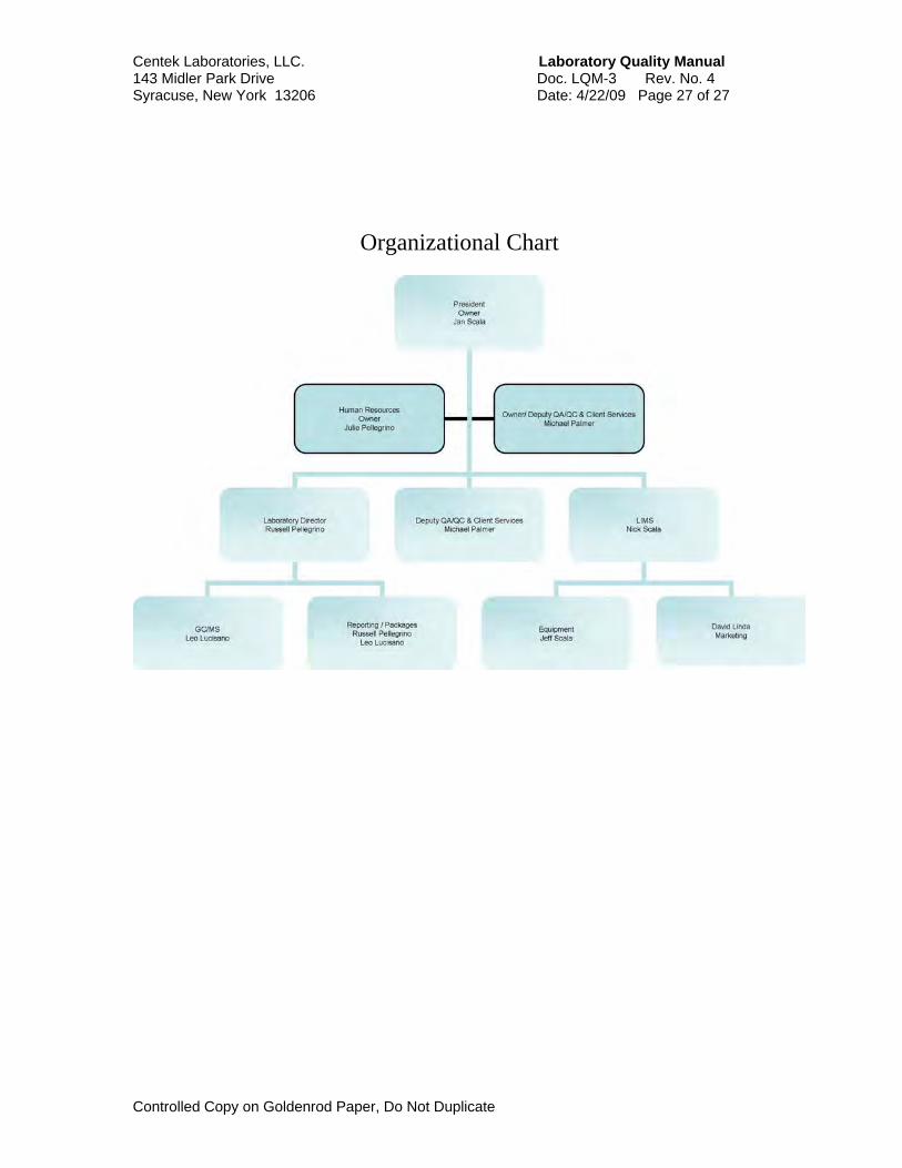
Centek Laboratories, LLC. Laboratory Quality Manual 143 Midler Park Drive Doc. LQM-3 Rev. No. 4 Syracuse, New York 13206 Date: 4/22/09 Page 27 of 27
Controlled Copy on Goldenrod Paper, Do Not Duplicate
Organizational Chart

TestAmerica Buffalo
SOP No. BF-MV-005, Rev. 1Effective Date: 08/25/2008
Page No.: 1 of 55221T
Facility Distribution No. ___________ Distributed To:_______________________
Title: Analytical Methods for the Analysis of GC/MS Volatiles [SW-846 Method 8260B]
Once printed, this is considered an uncontrolled document
Approvals (Signature/Date):
07/24/2008______ _ 07/25/2008___ James J. Lis Date Kene Kasperek Date Department Manager Health & Safety Manager / Coordinator
07/24/08_ 07/25/2008__ Peggy Gray-Erdmann Date Chris Spencer Date Quality Assurance Manager Laboratory Director
Copyright Information: This documentation has been prepared by TestAmerica Laboratories, Inc. and its affiliates (“TestAmerica”), solely for their own use and the use of their customers in evaluating their qualifications and capabilities in connection with a particular project. The user of this document agrees by its acceptance to return it to TestAmerica upon request and not to reproduce, copy, lend, or otherwise disclose its contents, directly or indirectly, and not to use it for any other purpose other than that for which it was specifically provided. The user also agrees that where consultants or other outside parties are involved in the evaluation process, access to these documents shall not be given to said parties unless those parties also specifically agree to these conditions. THIS DOCUMENT CONTAINS VALUABLE CONFIDENTIAL AND PROPRIETARY INFORMATION. DISCLOSURE, USE OR REPRODUCTION OF THESE MATERIALS WITHOUT THE WRITTEN AUTHORIZATION OF TESTAMERICA IS STRICTLY PROHIBITED. THIS UNPUBLISHED WORK BY TESTAMERICA IS PROTECTED BY STATE AND FEDERAL LAW OF THE UNITED STATES. IF PUBLICATION OF THIS WORK SHOULD OCCUR THE FOLLOWING NOTICE SHALL APPLY: ©COPYRIGHT 2008 TESTAMERICA LABORATORIES, INC. ALL RIGHTS RESERVED.

SOP No. BF-MV-005, Rev. 1Effective Date: 08/25/2008
Page No.: 2 of 55221T
Company Confidential & Proprietary
1.0 Scope and Application 1.1 Analytes, Matrix(s), and Reporting Limits 1.1.1 Methods 8260B -5 mL aqueous purge, 8260B - 25mL aqueous purge, 8260B – 5gr soil
and 8260B – medium level soil. 1.1.2 Applicable matrices include all aqueous samples, sediment, and soil. 1.1.3 The standard reporting limit (RL) is established at or above the low-level standard in the
calibration curve. For a 5-ml purge volume, the RL for the majority of compounds is 1 ug/l.
On occasion clients may request modifications to this SOP. These modifications are handled following the procedures outlined in Section xx in the Quality Assurance Manual. 2.0 Summary of Method
2.1 This analytical method is utilized for the analysis of water, sediment and soil from hazardous waste sites for the organic compounds listed in table 1.
2.2 The method includes sample preparation and analyses by purge and trap gas
chromatograph/mass spectrometer (GC/MS). Method can be used for 5mL purge or 25mL purge (concentrations adjusted accordingly).
2.3 Volatile compounds are extracted from sample matrix by the purge and trap method.
Analytes are desorbed onto a capillary column. An appropriate ramping temperature program is applied to maximize separation and achieve the correct resolution between the analytes. A mass spectrometer detector (MSD) interfaced to the gas chromatograph (GC) is utilized to detect analytes of interest.
2.4 Analytes eluted from the capillary column are introduced into the mass spectrometer via a
direct connection. Identification of target analytes is accomplished by comparing their mass spectra with the electron impact spectra of authentic standards. Quantitation is accomplished by comparing the response of a major (quantitation) ion relative to an internal standard using a minimum of a five-point calibration curve.
3.0 Definitions 3.1 VBLK - Volatile blank: VBLK’s are made from laboratory produced volatile free water.
They are analyzed before samples to ensure a clean laboratory environment and analytical system.
3.2 IBLK – Instrument Blank: IBLK’s are made from laboratory produced volatile free water.
They are analyzed after high level samples to verify that the system is clean and demonstrate the absence of carryover.

SOP No. BF-MV-005, Rev. 1Effective Date: 08/25/2008
Page No.: 3 of 55221T
Company Confidential & Proprietary
4.0 Interferences 4.1 Airborne contamination may result from solvent vapors. VBLKs and IBLKs will be utilized
to demonstrate a clean system and laboratory environment. 4.2 Some volatile compounds can permeate through a sample septum seal during storage or
shipment. A weekly volatile holding blank is stored in all sample incubators to monitor contamination.
4.3 Contamination by carryover can occur whenever a sample with high concentrations of
target compounds precedes a sample with low levels. The purging device, syringe and lines are flushed between every analysis to reduce carry over contamination. The trap is baked at 2600 C between each analysis.
5.0 Safety Employees must abide by the policies and procedures in the Corporate Environmental Health and Safety Manual (CW-E-M-001) and this document. This procedure may involve hazardous material, operations and equipment. This SOP does not purport to address all of the safety problems associated with its use. It is the responsibility of the user of the method to follow appropriate safety, waste disposal and health practices under the assumption that all samples and reagents are potentially hazardous. Safety glasses, gloves, lab coats and closed-toe, nonabsorbent shoes are a minimum.
5.1 Specific Safety Concerns or Requirements
5.1.1 The gas chromatograph and mass spectrometer contain zones that have elevated
temperatures. The analyst needs to be aware of the locations of those zones, and must cool them to room temperature prior to working on them.
5.1.2 The mass spectrometer is under deep vacuum. The mass spectrometer must be brought
to atmospheric pressure prior to working on the source. 5.1.3 There are areas of high voltage in both the gas chromatograph and the mass
spectrometer. Depending on the type of work involved, either turn the power to the instrument off, or disconnect it from its source of power.
5.2 Primary Materials Used
The following is a list of the materials used in this method, which have a serious or significant hazard rating. Note: This list does not include all materials used in the method. The table contains a summary of the primary hazards listed in the MSDS for each of the materials listed in the table. A complete list of materials used in the method can be found in the reagents and materials section. Employees must review the information in the MSDS for each material before using it for the first time or when there are major changes to the MSDS.

SOP No. BF-MV-005, Rev. 1Effective Date: 08/25/2008
Page No.: 4 of 55221T
Company Confidential & Proprietary
Material
Hazards
Exposure Limit (1)
Signs and symptoms of exposure
Methanol Flammable Poison Irritant
200 ppm-TWA
A slight irritant to the mucous membranes. Toxic effects exerted upon nervous system, particularly the optic nerve. Symptoms of overexposure may include headache, drowsiness and dizziness. Methyl alcohol is a defatting agent and may cause skin to become dry and cracked. Skin absorption can occur; symptoms may parallel inhalation exposure. Irritant to the eyes.
1 – Exposure limit refers to the OSHA regulatory exposure limit.
6.0 Equipment and Supplies 6.1 Instrumentation 6.1.1 Purge and trap devices
• Varian Archon Auto sampler • Encon Concentrator • O/I Analytical Auto sampler and Concentrator • Centurion Auto sampler
6.1.2 Trap Packing - Supelco Vocarb 3000
• Packing Material: • 10cm Carbpack B • 6cm Carboxen 1000 • 1cm Carboxen 1001
6.1.3 Gas Chromatograph/Mass Spectrometer (GC/MS) - GC: HP5890, MS:
• Gas chromatograph Column - J&W Scientific DB-624 or Phenomenex ZB-624 • Internal diameter: 0.25mm or 0.18mm • Length: 20m, 30m or 60m. • Coating: Cyanopropylphenyl Methyl Silicone
• Film thickness: 1.0um or 3.0µm 6.1.4 Data System
• Dell computer with Chemstation enviroquant software • Gas Chromatograph/Mass Spectrometer (GC/MS)-GC: HP6890 or HP7890, MS: Hewlett-
Packard/Agilent 5973N or 5975. • ProLab Resources software
6.1.5 Analytical Balance Mettler - Toledo Inc. Mettler AE160 6.2 Supplies
• Syringes - Hamilton Syringes size, 10ul, 25ul, 50ul, 100ul, 500ul, 1ml, 5ml, 10ml, 25ml • Pasteur Pipettes – disposable • Vials and caps - 2ml disposable • Vials and caps - 40ml disposable • Volumetric flasks - Pyrex 2ml, Pyrex 10ml, Pyrex 50ml, Pyrex 100ml • pH paper - wide range -.EM Science

SOP No. BF-MV-005, Rev. 1Effective Date: 08/25/2008
Page No.: 5 of 55221T
Company Confidential & Proprietary
7.0 Reagents and Standards 7.1 Reagent Water - For volatile analysis, the reagent water is volatile free and is prepared
by passing water through a carbon trap. 7.2 Methanol - Burdick & Jackson, purge and trap grade 7.3 Stock Standards - Are purchased as certified standard mixtures. Traceability is
documented following the procedures in the "Standards Traceability and Preparation Logbooks" SOP# AGP-STD-14. Individual compounds are prepared using reagent grade chemicals following the "Primary Standards Preparation" SOP# AMV-STD-25.
7.3.1 Stock Target Compound Mix – Is composed of three different mixtures.
7.3.1.1 The Gas Mix (See Table 6 for component list) is purchased from Supelco (or equivalent vendor) at a concentration of 2000ug/ml.
7.3.1.2 The 54 Component Mix (See Table 7 for component list) is purchased from Supelco
(or equivalent vendor) at a concentration of 2000ug/ml.
7.3.1.3 The 8260+ Mix (See Table 8 for component list) is purchased from Restek (or equivalent vendor) and is composed of four separate mixtures.
• 8260+ Mix #1 is purchased at a concentration of 1000ug/ml.
• 8260+ Mix #2 is purchased at a concentration of 5000ug/ml.
• 8260+ Mix #3 is purchased at a concentration of 20000ug/ml.
• 8260+ Mix #4 is purchased at a concentration of 5000ug/ml. 7.3.2 Stock Calibration Verification Mix – Is composed of two different mixtures.
7.3.2.1 The Second Source Mix (See Table 9 for component list) is purchased from Ultra (or equivalent vendor) at a concentration of 2000ug/ml.
7.3.2.2 The 8260+ Second Source Mix (See Table 10 for component list) is purchased from
Supelco (or equivalent vendor) and is composed of two separate mixtures.
• 8260+ Second Source Mix #1 is purchased at a concentration of 1000ug/ml.
• 8260+ Second Source Mix #2 is purchased at a concentration of 5000ug/ml. 7.3.3 Stock Internal Standard Solution – A mixture of 1,4-Dichlorobenzene-d4,
Chlorobenzene-d5 and 1,4-Difluorobenzene in Methanol is purchased from Restek (or equivalent vendor) at a concentration of 2500ug/ml.
7.3.4 Stock System Monitoring Solution – A mixture of Dibromofluoromethane, Toluene-D8,
4-Bromofluorobenzene and 1,2-Dichloroethane-d4 in Methanol is purchased from Ultra (or equivalent vendor) at a concentration of 2500ug/ml.

SOP No. BF-MV-005, Rev. 1Effective Date: 08/25/2008
Page No.: 6 of 55221T
Company Confidential & Proprietary
7.3.5 Stock Matrix Spike Solution – A 5 component mixture of 1,1-dichloroethene, trichloroethene, chlorobenzene, toluene, and benzene in Methanol is purchased from Restek (or equivalent vendor) at a concentration of 2500ug/ml.
7.3.6 Stock BFB Solution – A solution of 4-Bromofluorobenzene in Methanol is purchased
from Supelco (or equivalent vendor) at a concentration of 25000ug/ml. 7.4 Secondary IS and System Monitoring Calibration Dilution Standards – these
solutions are used for the manual injections required to prepare the initial calibration. 7.4.1 Internal Standard Solution - 80ul of stock standard IS solution (2500ug/ml) is added to
approximately 1 ml of purge and trap grade methanol in a 2 ml Class A volumetric, and then brought up to final volume of 2 ml with additional purge and trap grade methanol for a final concentration of 100ng/ul.
7.4.2 System Monitoring Compound Solution - 80ul of stock standard Surrogate solution
(2500ug/ml) is added to approximately 1 ml of purge and trap methanol in a 2 ml Class A volumetric, and then brought up a final volume of 2ml with additional purge and trap grade methanol for a final concentration of 100ng/ml.
7.4.3 To calculate appropriate expiration dates, refer to “Standards Traceability and Preparation
Logbooks”. 7.5 Working Standards 7.5.1 Intermediate Calibration Solution (Three individual mixtures)
7.5.1.1 250ul of stock standard Gas Mix solution (2000ug/ml) is added to approximately 4 ml
of purge and trap methanol in a 5ml Class A volumetric, and then brought up a final volume of 5ml with additional purge and trap grade methanol for a final concentration of 100ng/ul.
7.5.1.2 500ul of stock standard 54 Component Mix solution (2000ug/ml) is added to
approximately 9ml of purge and trap methanol in a 10ml Class A volumetric, and then brought up a final volume of 10ml with additional purge and trap grade methanol for a final concentration of 100ng/ul.
7.5.1.3 1000ul of each of the four stock standard 8260+ Mixes are added to approximately
9ml of purge and trap methanol in a 10ml Class A volumetric, and then brought up a final volume of 10ml with additional purge and trap grade methanol.
7.5.2 Matrix Spike Solution - 100ul of stock standard 5 component solution (2500ug/ml) is
added to approximately 4 ml of purge and trap methanol in a 5 ml Class A volumetric, and then brought up a final volume of 5ml with additional purge and trap grade methanol for a final concentration of 50ng/ul.
7.5.3 A Full List Matrix Spike Standard is made from stock Calibration Verification Standards
and is composed of two mixes.
7.5.3.1 250ul of stock standard Gas Mix solution (2000ug/ml) is added to approximately 4 ml

SOP No. BF-MV-005, Rev. 1Effective Date: 08/25/2008
Page No.: 7 of 55221T
Company Confidential & Proprietary
of purge and trap methanol in a 5ml Class A volumetric, and then brought up a final volume of 5ml with additional purge and trap grade methanol for a final concentration of 100ng/ul.
7.5.3.2 200ul of each of the two stock standard 8260+ Second Source Mixes are added to
approximately 1ml of purge and trap methanol in a 2ml Class A volumetric, and then brought up a final volume of 2ml with additional purge and trap grade methanol.
7.5.4 Working Internal Standard and System Monitoring Compound Solutions – for auto
injection by instrument.
7.5.4.1 Working Internal Standard Solution - An Internal Standard Mixture is made from IS stock standard (2500ug/ml) at 140ng/ul to 175ng/ul, depending on sample loop size, for the auto sampler and is made at 220ng/ul to 280ng/ul, depending on sample loop size, for the auto sampler.
7.5.4.2 Working System Monitoring Calibration Solution - A System Monitoring
Compounds Mixture is made from Surrogate stock standard (2500ug/ml) at 140 ng/ul to 175 ng/ul depending on sample loop size, for the auto sampler and is made at 220ng/ul to 280ng/ul, , depending on sample loop size, for the auto sampler.
7.5.5 Tuning Mixture - 4ul of stock solution 4-Bomofluorobenzene (BFB) tuning mixture is
added to approximately 1 ml of purge and trap grade methanol in a 2 ml Class A volumetric, and then brought up to final volume of 2 ml with additional purge and trap grade methanol for a final concentration of 50ng/ul.
7.5.6 Working Initial Calibration Standards
7.5.6.1 Water: 25 mL
7.5.6.1.1 20ul, 10ul and 5ul each of Intermediate Calibration Solution (10.5.1) is added to reagent water in each of three 50ml volumetric flasks. 20ul, 10ul and 5ul each of the Secondary IS Calibration Dilution Solution and also the Secondary System Monitoring Calibration Dilution Solution are added to the respective 50 ml volumetric flasks. The flasks are brought to volume with reagent water to prepare the 40, 20 and 10 ug/L standards respectively.
7.5.6.1.2 4ul and 1ul each of Intermediate Calibration Solution ((10.5.1) plus 4ul and 1ul
each of the Secondary IS Calibration Dilution Solution and also the Secondary System Monitoring Calibration Dilution Solution are added to reagent water in 100 ml volumetric flasks. The flasks are brought to volume with reagent water to prepare the 4ug/L and 1 ug/L standards respectively.
7.5.6.1.3 Each standard is then transferred into a 40ml vial and loaded onto the auto
sampler.
7.5.6.2 Water: 5 mL
7.5.6.2.1 50ul, 25ul, 12.5ul, 5ul into 50 ml and 1ul into 100ml each of Intermediate Calibration Solution (10.5.1) plus the same amounts of Secondary IS

SOP No. BF-MV-005, Rev. 1Effective Date: 08/25/2008
Page No.: 8 of 55221T
Company Confidential & Proprietary
Calibration Solution and Secondary System Monitoring Calibration Solution are (100ng/ml) are added to five individual 50ml volumetric flasks continuing reagent water to prepare 100, 50, 25, 10 and 1ug/L standards respectively.
7.5.6.2.2 Each standard is then transferred into a 40ml vial and loaded onto the auto
sampler.
7.5.6.3 Soil:
7.5.6.3.1 100ul, 50ul, 25ul, 10ul and 2.5ul of Intermediate Calibration Solution (10.5.1) plus the same amounts of Secondary IS Calibration Solution and Secondary System Monitoring Calibration Solution (at 100ng/ml) are added to five individual 50ml volumetric flasks containing reagent water. The final concentration of each standard is 200, 100, 50, 20 and 5 ug/kg, respectively.
7.5.6.3.2 5 ml of each standard is then transferred into five individual 40ml vials and
loaded onto the auto sampler.
7.5.7 Continuing Calibration Standard
7.5.7.1 Water: 25 ml
7.5.7.1.1 5ul of stock target compound mix is added to 50ml of DI water to make a final concentration of 10ppb. Pour standard into 40ml vial; working standard internal standard and system monitoring compounds are added by auto sampler.
7.5.7.2 Water: 5 ml
7.5.7.2.1 12.5ul of stock target compound mix is added to 50ml of DI water to make a
final concentration of 25ppb. Pour standard into 40ml vial; working standard internal standard and system monitoring compounds are added by the auto sampler.
7.5.7.3 Soil: 25ul of stock target compound is added to 50ml of DI water to make a final
concentration of 50ppb. Take 5ml and transfer it into a 40ml; working standard internal standard and system monitoring compounds are added by the auto sampler.
7.6 Storage of Standards 7.6.1 Stock and secondary dilution standards are stored in Teflon-sealed crimp cap vials at –
100 C to –200 C. 7.6.2 Aqueous standards are stored in Teflon-sealed crimp cap bottles at 40 C + 2o C.
8.0 Sample Collection, Preservation, Shipment and Storage
8.1 Samples are collected in 40 mL vials with caps and septa, preserved to a pH < 2 with
Hydrochloric Acid and stored at 4+2 degrees C until time of analysis.

SOP No. BF-MV-005, Rev. 1Effective Date: 08/25/2008
Page No.: 9 of 55221T
Company Confidential & Proprietary
8.2 Holding time for unpreserved samples is 7 days from sample date. For preserved samples the holding time is 14 days from sample date.
8.3 For some clients, regulatory agencies or QAPPS, the specified holding times may be
different than those described in 8.2. In those cases, consult the specific Protocol/Method/QAPP or Project Manager for holding time details.
8.4 Sample Storage
• Volatile samples are stored at 4+20C from the time of collection until analysis. • Volatile samples are stored together in refrigerators specifically designated for volatiles
only. • Storage blanks are stored with samples until analysis. • Samples and extracts are stored separately. • Volatile samples and standards are stored separately.
8.5 Preparation Of MS/MSD Samples 8.5.1 Water Samples: 40ml vial is spiked with 8ul of 50ng/ul matrix spike standard for 25ml
purge and 40ul for the 5ml purge. This corresponds to a final concentration in the samples of 10 ug/L and 50 ug/L respectively. Analysis proceeds according to procedures described for water analysis.
8.5.2 Low Level Soil/Sediment Samples: 5ul of matrix spiking solution is added to a 5g aliquot
of sample. This corresponds to a final concentration in the samples of 50 ug/kg. Analysis proceeds according to procedures described for low-level soil/sediment samples.
8.5.3 Medium Level Soil/Sediment Samples: 1ml of methanol containing the soil spiking
solution is combined with 50 mL of water and 50 ul of spiking solution is added to the methanol extraction solution. Sample analysis proceeds according to procedures described for medium level soil/sediment samples.
9.0 Quality Control
9.1 Blank Analysis 9.1.1 Method Blank: A method blank consisting of a clean reference matrix (reagent water or
purified quartz sand) must be analyzed prior to the analysis of samples but following any standard analysis.
• Target compounds detected in a method blank must fall below the reporting limit,
unless specified in client QAPP.
• If internal standard or systems monitoring compound recoveries are not met, the method blank must be reanalyzed before the analysis of samples.
9.1.2 Storage (Holding) Blank: A weekly holding blank is analyzed to determine if cross
contamination occurs within the volatile holding area. The results are reviewed by the quality assurance department and deemed acceptable or not acceptable. Corrective action, if necessary, will be taken.

SOP No. BF-MV-005, Rev. 1Effective Date: 08/25/2008
Page No.: 10 of 55221T
Company Confidential & Proprietary
9.1.3 Instrument Blank: An instrument blank consisting of a clean reference matrix analyzed
after the analysis of samples containing target compounds which exceed the calibration range. Multiple instrument blanks are shot until the instrument blank meets the criteria for method blanks.
9.2 Matrix Spike Blank (MSB/LCS) An aliquot of clean reference material spiked with the matrix spiking solution is analyzed with each analytical batch. The standard from which the MSB/LCS is prepared is purchased from an alternate vender from the continuing (CCV) standard. The solution is spiked at a concentration of 10ug/L for 25ml analysis and 25ug/L for 5ml analysis. A matrix spike blank duplicate is performed when insufficient volume is available for sample specific MS/MSD quality control.
9.2.1 The MSB/LCS must fall within internally derived statistical control limits or where
applicable the limits specified by a project QAPP. 9.2.2 Routine compounds included in the MSB/LCS are:
1,1-Dichloroethene; Chlorobenzene; Toluene; Benzene; Trichloroethene
9.2.3 When required, the MSB/LCS a ‘full-compound’ spike will be prepared and the MSB/LCS
will be spiked with all compounds of interest. Due to the potentially large number of target compounds for method 8260B, it is possible that a few of the spiking compound could fall outside limits in the MSB/LCS. If a compound falls outside limits biased high and that compound is not found in the samples, a comment will be made in the case narrative and the data will be found to be acceptable.
9.2.4 If the results of sample matrix spikes fall outside of the quality control range due to matrix,
the MSB is used to verify that the laboratory can perform a spike on a clean matrix. 9.3 Matrix Spike And Matrix Spike Duplicate Analysis A matrix spike and matrix spike
duplicate consisting of an actual field sample which has been spiked with the matrix spiking solution.
9.3.1 Matrix spike and matrix spike duplicate analysis will not be performed on rinsates or
field/trip blanks. 9.3.2 If a sample has not been designated for MS/MSD analysis by the client, a sample will be
selected at the analyst’s discretion. MS/MSD analysis will be performed at a minimum of every 20 samples.
9.3.3 If insufficient sample was received for a designated MS/MSD the client will be contacted
with the laboratory's in-house designated sample for MS/MSD analysis. If no MS/MSD is required, the instance will be documented in the SDG narrative.
9.3.4 If medium level analysis is required on the client designated sample, the laboratory
analyst will choose a low level sample on which to perform the quality control analysis. Medium level QC will also be performed.
9.4 Data Assessment & Acceptance Criteria for QC Measures

SOP No. BF-MV-005, Rev. 1Effective Date: 08/25/2008
Page No.: 11 of 55221T
Company Confidential & Proprietary
9.4.1 Technical Acceptance Criteria For Initial Calibration
9.4.1.1 SPCCs (System performance check compounds) are compounds used to check compound instability degradation. The following average minimum average response factors must be met before the curve can be used.
Chloromethane 0.10
1,1-Dichloroethane 0.10
Bromoform 0.10
Chlorobenzene 0.30
1,1,2,2-Tetrachloroethane 0.30
9.4.1.2 CCCs (Calibration Check Compounds) evaluate the calibration based on the integrity
of the system. The % RSD for the CCCs MUST be equal or less than 30%. The CCCs are:
Vinyl chloride
1,1-Dichloroethene
Chloroform
1,2-Dichloropropane
Toluene
Ethyl benzene
If the % RSD of any of the target analytes is 15% or less, the average response factor is assumed constant and the average response factor may be used for quantitation. OR If the % RSD of a target analyte is greater than 15%, linear regression may be used providing the coefficient of determination is greater than or equal to 0.99.
9.4.2 Technical Acceptance Criteria For Continuing Calibration
9.4.2.1 SPCCs - A system performance check is made daily or during every 12 hour analytical shift. Each compound must meet its minimum response factor (see Initial Calibration Criteria).
9.4.2.2 CCCs - Used to check the validity of the initial calibration. The % Difference for each
CCC shall be less than or equal to 20% from the initial calibration for the continuing calibration to be valid. All non-CCC target compounds must be less than 100% difference.
9.4.2.3 Internal Standard Retention Time – The retention times for all internal standards
must be evaluated to make sure that they are no more than 30 seconds from that of the midpoint of the initial calibration. If the retention time shift is greater than 30 seconds, the system must be inspected for malfunctions and maintenance must be performed, as required.

SOP No. BF-MV-005, Rev. 1Effective Date: 08/25/2008
Page No.: 12 of 55221T
Company Confidential & Proprietary
9.4.2.4 Internal Standard Response – The EICP area for all internal standards must be evaluated to make sure that they have not change by a factor greater than two (-50% to +100%) from that of the midpoint of the initial calibration. If the response exceeds these limits, the system must be inspected for malfunctions and maintenance must be performed, as required.
9.4.3 Technical Acceptance Criteria of Quality Control Samples
Samples, blanks, matrix spikes, and matrix spike duplicates must meet internal standard and system monitoring compound recovery limits. Where the Internal Standard recovery limit equals sample internal standard characteristic ion area (EICP) divided by the CCV internal standard characteristic ion area (EICP), multiplied by 100.
9.5 Corrective Action for Out-of-Control Data 9.5.1 Corrective Actions For MS/MSD
9.5.1.1 If the recoveries of the internal standards and system monitoring compounds do not agree with the unspiked sample (i.e. the sample recoveries were within control limits and MS/MSD recoveries were outside of control limits) the MS/MSD will be evaluated. The analyst will use their technical judgment to determine if the non-conformance is due to sample matrix or laboratory error. If it is determined that the QC failure was due to laboratory error, then reanalysis will occur.
9.5.1.2 If the recoveries of the internal standards and system monitoring compounds agree
with the unspiked sample (i.e. both the sample and MS/MSD recoveries were outside of control limits) re-analysis is not required. The instance will be documented in the SDG narrative.
9.5.1.3 Limits for the matrix spiking compounds are established by the laboratory on an
annual basis. If the concentrations determined in the MS/MSD do not meet the control limits, no corrective action is necessary as long as the MSB/LCS was within control limits. The instance will be documented in the job narrative.
9.5.2 Corrective Actions For Initial Calibration
9.5.2.1 If technical acceptance criteria cannot be met, it may be necessary to re-analyze the initial calibration. If after re-analysis, the criteria have not been met, it may be necessary to inspect the GC/MS system for possible problems.
9.5.2.2 Corrective actions may require one or several of the following procedures:
• Open new/remake standard mixes
• The ion source may be cleaned
• The column may be cut at the injection port end
• Change the purge trap on the purge and trap unit
• Correct purge gas flow to optimize response
SOP No. BF-MV-005, Rev. 1Effective Date: 08/25/2008
Page No.: 13 of 55221T
Company Confidential & Proprietary
• The column may be baked out
• The purge trap may be baked out
• The column may be replaced 9.5.3 Corrective Actions for Failure to Meet the Continuing Calibration Acceptance
Criteria
9.5.3.1 If the technical acceptance criteria given above are not met, it may be necessary to re-analyze the continuing calibration check. If, after re-analysis, the given criterion has not been met, it may be necessary to re-analyze the initial calibration.
9.5.3.2 Other Corrective actions may be taken. The following details possible corrective
actions:
• Open new/remake standard mixes
• The ion source may be cleaned
• The column may be cut at the injection port end
• The trap on the purge and trap unit may be replaced
• The purge gas flow may be adjusted
• The column may be baked out
• The purge trap may be baked out
• The column may be replaced
9.5.4 Corrective Actions For Samples
9.5.4.1 If the internal standard or system monitoring criteria are not met, the sample must be re-analyzed to insure that it was not an internal problem that affected recoveries. If, after re-analysis, recoveries are outside of control limits, a matrix effect can be assumed.
9.5.4.2 When dilutions are performed, target compound concentration must fall within the
upper range of the initial calibration. If any target compound exceeds the calibration range, the sample would require dilution. The sample immediately following a sample with target compounds above the calibration range must be monitored to insure that there is no carryover present. If there is a possibility of carryover, that sample must be re-analyzed.
9.5.4.3 If matrix effects exist, and both analyses exhibit recoveries outside of control limits,
both analyses will be reported and documented in the job narrative. 9.5.4.4 If, after re-analysis, recovery criteria are met, only the second analyses will be
reported. If the second analyses occur outside of the contract required holding time, both analyses will be reported in that instance.
9.5.4.5 In the case of a matrix spike or matrix spike duplicate, these samples should only be

SOP No. BF-MV-005, Rev. 1Effective Date: 08/25/2008
Page No.: 14 of 55221T
Company Confidential & Proprietary
reanalyzed if the recoveries do not agree with the unspiked sample. If recoveries agree, the unspiked sample will not require re-analysis. The instance will be documented in the SDG narrative.
9.5.5 Corrective Actions for Failure to Meet the Matrix Spike Blank Acceptance Criteria
9.5.5.1 Limits for the matrix spiking compounds are established by the laboratory on an annual basis. The MSB/LCS must fall within these control limits. When required, the MSB/LCS will be spiked with all compounds of interest, otherwise spiked to include a minimum of 1,1-dichloroethene, trichloroethene, chlorobenzene, toluene, and benzene. Due to the potentially large number of target compounds for method 8260B, it is possible that a few of the spiking compounds could fall outside limits in the MSB/LCS. If a compound falls outside limits biased high and that compound is not found in the samples, a comment will be made in the case narrative and the data will be found to be acceptable
9.5.5.2 If the technical acceptance criteria are not met, it may be necessary to re-analyze the
matrix spike blank. If, after re-analysis, the given criterion has not been met, it may be necessary to re-analyze the initial calibration.
9.5.5.3 Other Corrective actions may be taken. The following details possible corrective
actions:
• Open new/remake standard mixes
• The ion source may be cleaned
• The column may be cut at the injection port end
• The trap on the purge and trap unit may be replaced
• The purge gas flow may be adjusted
• The column may be baked out
• The purge trap may be baked out
• The column may be replaced
9.5.6 Contingencies for Handling Out-of-Control or Unacceptable Data
• Inform project manager for client input and fill out job exception report.
• Rerun samples to confirm results.
• Resample if client or project manager requests.
10.0 Procedure
10.1 Calibration & Standardization 10.1.1 Instrument Tuning and Performance Check: The GC/MS system is calibrated using Perflurotributylamine (PFTBA) according to the

SOP No. BF-MV-005, Rev. 1Effective Date: 08/25/2008
Page No.: 15 of 55221T
Company Confidential & Proprietary
recommended tuning conditions suggested by the vendor. An instrument performance check of Bromofluorobenzene (BFB) is analyzed at the beginning of each 12-hour analysis period. The analysis of the instrument performance check is performed using the following procedure:
• 1ul of a 50ng/ul solution is directly injected, resulting in a 50ng injection of BFB into the GC/MS.
• A blank containing 50 ng BFB is purged. 10.1.2 The mass spectrum of BFB is acquired using the following procedure:
• A single scan on the peak. • An average of the peak. • The apex scan, one scan immediately preceding the apex and one scan immediately
following the apex are averaged. The spectrum is background subtracted using a single scan no more than 20 scans prior to the elution of BFB.
• The mass spectrum of BFB must pass the technical acceptance criteria given in Table 2. 10.1.3 Initial Calibration (ICAL): The instrument performance check must meet the technical acceptance criteria prior to the analysis of an initial curve or samples. The GC/MS system is calibrated using five levels of concentrations. All compounds of interest are included. (See section 9.4 for initial calibration acceptance criteria.) Solutions containing target compounds and system monitoring compounds are analyzed at concentrations of 5, 20, 50, 100 and 200 ug/L. (1, 4, 10, 20 and 40 ug/L for 25 mL)
5 ml (aqueous) or 5 gram (soil) Purge Analysis
Standard
Solvent
Working Standard
Conc.
Amount Added
(ul)
Final Vol.
(mL)
Final Conc. Water (ug/L)
Final Conc. Soil
(ug/kg)
VSTD001 MeOH 100ng/ul 1 100 1 5
VSTD010 MeOH 100ng/ul 5 50 10 20
VSTD025 MeOH 100ng/ul 12.5 50 25 50
VSTD050 MeOH 100ng/ul 25 50 50 100
VSTD100 MeOH 100ng/ul 50 50 100 200
25 ml Purge Analysis
Standard
Solvent
Working Standard
Conc.
Amount Added
(ul)
Final Vol.
(mL)
Final Conc. Water (ug/L)
VSTD001 MeOH 100ng/ul 1 100 1
VSTD004 MeOH 100ng/ul 4 100 4
VSTD010 MeOH 100ng/ul 5 50 10

SOP No. BF-MV-005, Rev. 1Effective Date: 08/25/2008
Page No.: 16 of 55221T
Company Confidential & Proprietary
VSTD020 MeOH 100ng/ul 10 50 20
VSTD040 MeOH 100ng/ul 20 50 40
10.1.4 Continuing Calibration Verification (CCV): Every 12 hours of sample analysis the laboratory must demonstrate that the instrument has drifted or changed minimally by performing an instrument performance check and continuing calibration verification. (See section 9.4 for continuing calibration acceptance criteria.) 10.2 Before Analysis 10.2.1 Once initial calibration criteria has been met, and prior to analyzing samples and required
blanks, Each GC/MS system must be routinely checked by analyzing a Continuing Calibration Verification (CCV) standard containing all compounds (including internal standards and system monitoring compounds) at a concentration of 25ug/L for 5ml or 10ug/L for 25ml analysis.
10.2.2 If time remains after initial calibration criteria have been met, it may not be necessary to
perform a CCV. The 25 ug/L (10ug/L for 25ml) standard may be evaluated against the new initial curve and used as the CCV.
10.2.3 If there is no time remaining in the 12-hour period, the instrument performance check
(BFB) must be analyzed along with a new CCV. 10.2.4 Procedure for Continuing Calibration: 12.5ul of internal standards, system monitoring
compounds, and target compound mixture is added to a 50ml volumetric flask. A 5ml aliquot is analyzed. 25ml purge analysis requires 5ul into a 50 ml volumetric flask filled with volatile free water.
10.3 Sample Analysis 10.3.1 BFB tuning criteria and GC/MS calibration verification must be met before sample analysis
begins. 10.3.2 The acquisition time of the BFB tune establishes a 12hr. batch. The CCV, MSB, and
VBLK must be analyzed within 12hrs, unless specified by the client request. The remaining time in the 12hr batch is utilized to run samples of similar matrix. All aqueous samples are considered a water matrix. All solid samples, with the exception of sludges, are considered soil matrix. Sludges are run medium level.
10.3.3 Samples and standard solutions are brought to ambient temperature before analysis. 10.3.4 Prior to the analysis of samples, a method blank must be analyzed in accordance with the
associated procedures for a given matrix. Technical criteria for method blanks must be met prior to sample analysis.
10.4 Water Sample Analysis 10.4.1 A 5ml sample aliquot is spiked with internal and system monitoring compounds to a final

SOP No. BF-MV-005, Rev. 1Effective Date: 08/25/2008
Page No.: 17 of 55221T
Company Confidential & Proprietary
concentration of 25 ug/L each. 25ml analysis requires a final concentration of 10ug/L. The spike may be performed manually with a Hamilton gas tight syringe or the auto sampler may be used. The sample is then loaded onto the auto sampler where it is in turn transferred to the purge chamber.
10.4.2 The sample is purged for 11.0 + 1 minute at ambient temperature. 10.4.3 At the end of the purge time, the sample is desorbed onto the gas chromatograph column
by rapidly heating the trap from 190C to 2500C (depending on manufacturer specifications) while the trap is back flushed with Helium between 20 - 60 ml/minute for two minutes. The sample is desorbed onto the column and the gas chromatograph temperature ramping program is commenced.
10.4.4 While the trap is in the bake mode, the purge chamber is flushed with two 5ml aliquots of
reagent water in order to avoid possible contamination from carryover of target compounds.
10.4.5 After the sample has desorbed, the trap is conditioned at 2600C for 8 minutes. After
baking, the trap is ready for the next sample. 10.4.6 Dilutions may be necessary if the concentration of any target compound exceeds the
working range of the calibration. 10.4.7 In the event that a dilution is required, a measured volume of sample is added to a
volumetric flask then to volume with reagent water and inverted 3 times. The sample in the neck portion is discarded and a 5ml volume is taken for analysis. Analysis may then proceed as described.
10.5 Low Level Soil/Sediment Sample Analysis 10.5.1 The low level soil method is based on a heated purge of a 5g sample mixed with reagent
water containing a final concentration of 50 ug/L of internal and system monitoring compounds.
10.5.2 If a dilution of the soil/sediment is required, a smaller portion of soil may be used. The
smallest amount of soil that may be used is 1g. If a higher dilution is required, the sample must be analyzed as a medium level soil/sediment.
10.5.3 Initial and continuing calibrations that are used for the quantitation of low soils/sediments
are analyzed using the same purge and trap conditions as samples. 10.5.4 The sample consists of the entire contents of the sample container. The contents are
mixed thoroughly with a narrow metal spatula or wooden tongue depressor. A 5g portion is taken for analysis. The weight is recorded to the nearest 0.01g.
10.5.5 A 5ml aliquot of reagent water containing internal standards and system monitoring
compounds is added to the sample immediately prior to heating and purging. 10.5.6 After reagent water is added, the soil/sediment sample is heated to 400C + 10C then
purged for 11 + 1 minutes.

SOP No. BF-MV-005, Rev. 1Effective Date: 08/25/2008
Page No.: 18 of 55221T
Company Confidential & Proprietary
10.5.7 After purging, the sample is subjected to desorbing as described for water analysis. 10.6 Medium Level Soil/Sediment Samples 10.6.1 The medium level soil/sediment method is based on an extraction of a portion of the
sample with methanol. A portion of the extract is then added to a 5 ml aliquot of reagent water containing internal and system monitoring compounds at a final concentration of 25ug/L.
10.6.2 The sample consists of the entire contents of the sample container. The contents are
thoroughly mixed with a thin metal spatula or wooden tongue depressor. A 4 g portion of the sample is weighed into a 20ml vial. The weight of the sample is recorded to the nearest 0.01g.
10.6.3 A 10ml aliquot of methanol is quickly added to the sample. The vial is capped and the
sample is shaken for 2 minutes. 10.6.4 A determined amount of methanol extract is added to a 5ml aliquot of reagent water
containing internal and system monitoring compounds at a final concentration of 50ug/L. Analysis may proceed according to procedures described for water samples.
10.6.5 Table 3 may be used to determine the volume of methanol extract required for a given
dilution factor. 10.7 pH Determinations For Water Samples 10.7.1 After the sample aliquots are taken from the VOA vials, the pH of the sample is
determined by placing several drops of sample, using a disposable pipette, onto pH paper. A checkmark will be entered in the injection logbook if the sample pH is <2, however if the sample demonstrates a pH>2, the actual pH will be noted in the injection logbook.
10.8 Percent Moisture Determinations 10.8.1 Immediately after weighing the sample for analysis, a 5-10g portion is weighed into a
tarred aluminum weigh pan. The sample is then dried overnight at 1050C. The sample is allowed to cool. The final weight is recorded. Using equation 4, the percentage moisture, which is used for reporting concentrations relative to the dry weight of the soil/sediment samples, may be determined. The following calculation is used to determine percent moisture:
Wt. of sample (g) – wt. of dried sample (g) %moisture = wt. of sample (g) X 100
11.0 Calculations / Data Reduction 11.1 Calculations For MS/MSD Samples

SOP No. BF-MV-005, Rev. 1Effective Date: 08/25/2008
Page No.: 19 of 55221T
Company Confidential & Proprietary
11.1.1 The calculations to determine concentrations are the same equations described for sample analysis of a given matrix.
11.1.2 The percent recovery of the matrix spiking compounds is determined using equation:
Matrix Spike Recovery = SSR - SR x 100 SA
Where: SSR = Spiked sample result SR = Sample results SA = Spike added 11.1.3 The relative percent difference (RPD) of the recoveries of each compound between the
matrix spike and matrix spike duplicate is determined using equation:
RPD = |MSR - MSDR| x 100 1/2 (MSR + MSDR)
Where: MSR = Matrix spike recovery MSDR = Matrix spike duplicate recovery 11.2 Calculations For Initial Calibration 11.2.1 The relative response factor (RRF) for each target compound and each system monitoring
compound is calculated using equation.
RRF= Ax x Cis Ais Cx
Where, Ax = Area of the characteristic ion (EICP) for the compound to be measured (see Table
6) Ais = Area of the characteristic ion (EICP for the specific internal standard (see Tables 5
and 6A) Cis = Concentration of the internal standard Cx = Concentration of the compound to be measured
11.2.2 The relative response factor of the Xylenes requires the use of the area response and the
concentration of the peak that represents the single isomer. 11.2.3 The relative response factor of 1,2-dichloroethene is calculated using the sum of the areas
of both isomers and the sum of the concentrations. 11.2.4 The average response factor (RRF) is calculated for all compounds of interest.

SOP No. BF-MV-005, Rev. 1Effective Date: 08/25/2008
Page No.: 20 of 55221T
Company Confidential & Proprietary
11.2.5 The relative standard deviation (% RSD) is calculated over the working range of the curve for all compounds using equation:
%RSD= Standard Deviation x 100 Mean
( )
1 DeviationStandard
n
−
−=
∑=
n
2i1i
χχ
Where, Xi = each individual value used to calculate the mean X = the mean of n values n = the total number of values
11.3 Calculations For Continuing Calibration 11.3.1 The relative response factor (RRF) for all target compounds and system monitoring
compounds is calculated using equation 1. 11.3.2 The percent difference between the initial calibration and the continuing calibration is
determined for all target compounds and system monitoring compound using equation: ___
%Difference = RRFc - RRFi x 100 ____ RRFi
Where, RRFc = Relative response factor from continuing calibration standard ____ RRFi = Mean relative response factor from the most recent initial calibration meeting
technical acceptance criteria 11.4 Percent Moisture Determinations 11.4.1 Immediately after weighing the sample for analysis, a 5-10g portion is weighed into a
tarred aluminum weigh pan. The sample is then dried overnight at 1050C. The sample is allowed to cool. The final weight is recorded. Using the equation for % moisture, concentrations relative to the dry weight of the soil/sediment samples, may be determined.
%moisture = g of wet sample - g of dry sample x100 g of wet sample
11.5 Quantitation of volatile target compounds is done using the internal standard method.
The internal standards used for each compound are assigned those indicated in table 5. The Internal Standard RRF of the continuing calibration is used in the quantitation calculation.

SOP No. BF-MV-005, Rev. 1Effective Date: 08/25/2008
Page No.: 21 of 55221T
Company Confidential & Proprietary
11.5.1 Water Samples: The following equation is used to calculate water samples:
Concentration ug/L = (Ax) (Is) (DF) __ (Ais) (RRF) (Vo)
Where, Ax = Area of the characteristic ion (EICP) for the compound to be measured (see Table
2) Ais = Area of the characteristic ion (EICP) for the specific internal standard (see Tables
5 and 6A) Is = Amount of internal standard added in nanograms (ng) RRF= Relative response factor from the ambient temperature purge of the calibration
standard. Vo = Volume of water purged in milliliters (mL) Df = Dilution factor. The dilution factor for analysis of water samples for volatiles by this
method is defined as the ratio of the number of milliliters (mL) of water purged (i.e., Vo above) to the number of mL of the original water sample used for purging. For example, if 2.0 mL of sample is diluted to 5 mL with reagent water and purged, Df = 5 mL/2.0 mL = 2.5. If no dilution is performed, Df = 1.
11.5.2 Low Level Soil/Sediment Samples - The following equation is used for low level
soil/sediment samples:
Concentration ug/Kg (dry weight basis) = (Ax) (Is) ______ (Ais) (RRF) (Ws) (D)
Where, Ax, Is, Ais are as given for water. RRF = Relative response factor form the heated purge of the calibration standard. D = 100 - % moisture 100 Ws = Weight of sample added to the purge tube, in grams (g). 11.5.3 Medium Level Soil/Sediment Samples The following equation is used for quantitation of medium level soil/sediment samples:
Concentration ug/Kg (Dry weight basis) = (Ax) (Is) (Vt) (1000) (Df) (Ais) (RRF) (Va) (Ws) (D)
Where, Ax, Is, Ais are as given for water. RRF = Relative response factor from the ambient temperature purge of the calibration
standard. Vt = Total volume of the methanol extract in milliliters (mL). NOTE: This volume is typically 10 mL, even though only 1 mL is transferred to the vial.

SOP No. BF-MV-005, Rev. 1Effective Date: 08/25/2008
Page No.: 22 of 55221T
Company Confidential & Proprietary
Va = Volume of the aliquot of the sample methanol extract (i.e., sample extract not including the methanol added to equal 100 uL) in micro liters (ul) added to reagent water for purging.
Ws = Weight of soil/sediment extracted, in grams (g). D = 100 - % moisture 100 Df = Dilution factor. The dilution factor for analysis of soil/sediment samples for
volatiles by the medium level method is defined as:
ul most conc. extract used to make dilution + ul clean solvent ul most conc. extract used to make dilution
(The dilution factor is equal to 1.0 in all cases other than those requiring dilution of the
sample methanol extract (Vt). The factor of 1,000 in the numerator converts the value of Vt from mL to ul.)
11.6 When quantitating the sample concentration of Xylenes (total), the areas of both the m & p
Xylene peak and the o-Xylene peak are summed and the RRF determined using equation 1 are used. The concentration of each peak may be determined separately and then summed to determine the concentration of Xylene (total).
11.7 When quantitating the concentration of 1,2-Dichloroethene (total), the concentrations of
the two isomers (cis and trans) are summed. 11.8 Secondary ion quantitation may be used if interferences (such as matrix effects) may
cause a bias in quantitation. If ions other then those listed in table 6 are used, the analyst will document the reason, and it will be noted in the job narrative.
11.9 If manual integration of any compound (including internal standards, system monitoring
compounds, target or tentatively identified compounds) is required, the EICP of that compound will be provided. All manual integrations will be identified with an "m" and initialed and dated by the GC/MS analyst.
11.10 Tentatively Identified Compounds 11.10.1 An estimated concentration for tentatively identified compounds will be determined
using the equations described above for a given matrix using the total area counts of both the tentatively identified compound and the nearest internal standard which is free of interferences.
11.10.2 The RRF used to determine all concentrations of tentatively identified compounds
will be an assumed RRF of one (1). 11.10.3 All tentatively identified compounds will be qualified as "J" (estimated) and "N"
(presumptive evidence).

SOP No. BF-MV-005, Rev. 1Effective Date: 08/25/2008
Page No.: 23 of 55221T
Company Confidential & Proprietary
11.11 System Monitoring Compounds 11.11.1 The recovery of all system monitoring compounds in samples, blanks matrix
spikes and matrix spike duplicates, is calculated using equation:
% Recovery = Concentration (amount) found x 100 Concentration (amount) spiked
11.11.2 The recovery limits for each system monitoring compound are laboratory
established on an annual basis. The recoveries must be within the criteria limits. If they fall outside criteria limits, the results must be evaluated and the sample reanalyzed, if necessary.
11.11.3 The relative retention time (RRT) of each system monitoring compound must be
within the acceptance windows of ±0.06 RRT. 11.12 Internal Standards 11.12.1 The internal standards of all samples, blanks, matrix spikes and matrix spike
duplicates must be monitored. The EICP area of each internal standard must be within the range of -50.0 percent to 200.0 percent of those in the continuing calibration.
11.12.2 The relative retention time (RRT) of each internal standard must be within 0.5
minutes (30 seconds) of those in the continuing calibration. 11.13 Verification of Calculated Result 11.13.1 The laboratory analyst/data entry analyst will print out and review sample
worksheets and hand calculate the result for positive hits, internal standards and surrogates for comparison to the AIMS calculated result. Corrective action will result, if needed.
12.0 Method Performance Each analyst prior to sample analysis will perform 4 replicate second source QC check standards, at 25ug/L, as an Initial Demonstration of Capability. The average recovery and standard deviation are keep in AIMS and kept with each analyst's training file. 12.1 Method Detection Limit Study (MDL) The method detection limit (MDL) is the lowest concentration that can be detected for a given analytical method and sample matrix with 99% confidence that the analyte is present. The MDL is determined according to the laboratory’s MDL procedure in the QA Manual. MDLs reflect a calculated (statistical) value determined under ideal laboratory conditions in a clean matrix, and may not be achievable in all environmental matrices. The laboratory maintains MDL studies for analyses performed; these are verified at least annually unless method requirements require a greater frequency.

SOP No. BF-MV-005, Rev. 1Effective Date: 08/25/2008
Page No.: 24 of 55221T
Company Confidential & Proprietary
12.2 Demonstration of Capabilities
12.2.1 A one–time initial demonstration of performance for each individual method for both soils and water matrices must be generated.
12.2.2 This requires quadruplicate analysis of a mid–level check standard containing all
of the standard analytes for the method using the same procedures used to analyze samples, including sample preparation.
12.2.3 Compare these results with the acceptance criteria given in the Method or to
laboratory historical limits (if available).
12.2.4 Repeat the test for any analyte that does not meet the acceptance criteria. Repeated failure for any analyte indicates the need for the laboratory to evaluate the analytical procedure and take corrective action.
12.3 Training Requirements
12.3.1 The supervisor has the responsibility to ensure that this procedure is performed by an analyst who has been properly trained in its use and has the required experience.
12.3.2 The following analyst validation information is maintained for this method in the laboratory QA files.
12.3.3 The analyst must complete the laboratory safety orientation training that includes, but is not limited to, chemicals, PPE requirements, and electrical safety.
12.3.4 The analyst must read and understand this SOP.
12.3.5 The analyst must read and understand the Method used as reference for this SOP.
12.3.6 The analyst must complete a DOC or successfully analyze PT samples annually.
12.3.7 The analyst must complete the TestAmerica Quality Assurance Training.
13.0 Pollution Control It is TestAmerica’s policy to evaluate each method and look for opportunities to minimize waste generated (i.e., examine recycling options, ordering chemicals based on quantity needed, preparation of reagents based on anticipated usage and reagent stability). Employees must abide by the policies in Section 13 of the Corporate Environmental Health and Safety Manual (CW-E-M-001) for “Waste Management and Pollution Prevention.” 14.0 Waste Management Waste management practices are conducted consistent with all applicable rules and regulations. Excess reagents, samples and method process wastes are disposed of in an accepted manner.

SOP No. BF-MV-005, Rev. 1Effective Date: 08/25/2008
Page No.: 25 of 55221T
Company Confidential & Proprietary
Waste description rules and land disposal restrictions are followed. Waste disposal procedures are incorporated by reference to the Corporate Safety Manual. The following waste streams are produced when this method is carried out. 14.1 Waste Streams Produced by the Method The following waste streams are produced when this method is carried out. 14.1.1 Spill Response: Any spills must be cleaned up immediately and handled correctly. Any
wastes that have a pH < 7 must be disposed of in an "A" waste container. Any wastes having a pH > 7 must be disposed of in a "D" waste container.
14.1.2 Aqueous waste generated from analysis: Any wastes that have a pH < 7 must be
disposed of in an "A" waste container. Any wastes having a pH > 7 must be disposed of in a "D" waste container.
14.1.3 Solvent waste generated from analysis: Solvent waste is stored in laboratory approved
metal waste receptacle and labeled "C" waste. Waste receptacles are then taken to sample control where they are then properly disposed of.
14.1.4 Solid waste generated from analysis: Solid volatile analysis waste consists of soils and
glass. The soil is wrapped in tin foil and placed in the solid waste receptacle. Soils used for dry weight measurements are also disposed of in this manner. Glass waste such as pipettes and vials are rinsed and disposed of in approved glass receptacles
14.1.5 Expired Standards: Expired and used standards are stored in a laboratory approved
metal waste receptacle labeled “BV”. Waste receptacles are then taken to sample control where they are then properly disposed of.
15.0 References / Cross-References
• Method 8260B, “Test Methods for Evaluating Solid Waste”; SW846, Third Edition, December 1996.
16.0 Method Modifications:
Item Method Modification
N/A
17.0 Attachments
Table 1. Compounds Determined by Method 8260B Table 2. BFB Key Ions and Ion Abundance Criteria Table 3. Volume of Medium Level Extracts for Dilution Table 4. Characteristic Masses (m/z) for Purgeable Organic Compounds Table 5. Job Summary Check List (Page 1 & 2) Tables 6-12. Composition of Stock Standards

SOP No. BF-MV-005, Rev. 1Effective Date: 08/25/2008
Page No.: 26 of 55221T
Company Confidential & Proprietary
18.0 Revision History
• Revision 0, dated 18 July, 2008 ─ Quality Director change, signature added ─ Section 6.0: Changed section to reflect current instrumentation and column specifications ─ Section 9: Added Trichloroethene to MSB list, took out duplicate Chlorobenzene ─ Minor grammatical changes
• Revision 01, dated -24 July, 2008 ─ Sec 2.4- removed reference to jet separator and added clarification to 5 point curve
reference ─ Section 7.5.5.2.1: Changed volumes used to make ICAL ─ Reduced throughout document volumes used from 25ul to 12.5ul. Also changed throughout
final concentrations from 50ppb to 25ppb. ─ Sec 9.2.3 and 9.5.5.1- replaced couple with few ─ Sec 9.4.1.2- removed reference to use of mean RSD ─ Sec 9.5.1.1- added text to clarify lab practice ─ Sec 10.1.3- fixed table to reflect concentrations and volumes used. ─ Sec 10.4.3- added temperature range due to variances in instrumentation

SOP No. BF-MV-005, Rev. 1Effective Date: 08/25/2008
Page No.: 27 of 55221T
Company Confidential & Proprietary
Table 1: Compounds Determined by Method 8260B
Appropriate Technique
Compound CAS No.b 5030/5035 5031 5032 5021 5041 Direct
Injection
Acetone 67-64-1 pp c c nd c c
Acetonitrile 75-05-8 pp c nd nd nd c
Acrolein 107-02-8 pp c c nd nd c
Acrylonitrile 107-13-1 pp c c nd c c
Allyl alcohol 107-18-6 ht c nd nd nd c
Allyl chloride 107-05-1 c nd nd nd nd c
Benzene 71-43-2 c nd c c c c
Benzyl chloride 100-44-7 c nd nd nd nd c
Bis(2-chloroethyl)sulfide 505-60-2 pp nd nd nd nd c
Bromoacetone 598-31-2 pp nd nd nd nd c
Bromochloromethane 74-97-5 c nd c c c c
Bromodichloromethane 75-27-4 c nd c c c c
4-Bromofluorobenzene (surr)
460-00-4 c nd c c c c
Bromoform 75-25-2 c nd c c c c
Bromomethane 74-83-9 c nd c c c c
n-Butanol 71-36-3 ht c nd nd nd c
2-Butanone (MEK) 78-93-3 pp c c nd nd c
t-Butyl alcohol 75-65-0 pp c nd nd nd c
Carbon disulfide 75-15-0 pp nd c nd c c
Carbon tetrachloride 56-23-5 c nd c c c c
Chloral hydrate 302-17-0 pp nd nd nd nd c
Chlorobenzene 108-90-7 c nd c c c c
Chlorobenzene-d5 (IS) c nd c c c c
Chlorodibromomethane 124-48-1 c nd c nd c c
Chloroethane 75-00-3 c nd c c c c
2-Chloroethanol 107-03-3 pp nd nd nd nd c
2-Chloroethyl vinyl ether 110-75-8 c nd c nd nd c
Chloroform 67-66-3 c nd c c c c
Chloromethane 74-87-3 c nd c c c c
Chloroprene 126-99-8 c nd nd nd nd c
3-Chloropropionitrile 542-76-7 l nd nd nd nd pc
Crotonaldehyde 4170-30-3 pp c nd nd nd c
1,2-Dibromo-3-chloropropane
96-12-8 pp nd nd c nd c
1,2-Dibromoethane 106-93-4 c nd nd c nd c
Dibromomethane 74-95-3 c nd c c c c
1,2-Dichlorobenzene 95-50-1 c nd nd c nd c

SOP No. BF-MV-005, Rev. 1Effective Date: 08/25/2008
Page No.: 28 of 55221T
Company Confidential & Proprietary
Appropriate Technique
Compound CAS No.b 5030/5035 5031 5032 5021 5041 Direct
Injection
1,3-Dichlorobenzene 541-73-1 c nd nd c nd c
1,4-Dichlorobenzene 106-46-7 c nd nd c nd c
1,4-Dichlorobenzene-d4 (IS)
c nd nd c nd c
cis-1,4-Dichloro-2-butene 1476-11-5 c nd c nd nd c
trans-1,4-Dichloro-2-butene
110-57-6 pp nd c nd nd c
Dichlorodifluoromethane 75-71-8 c nd c c nd c
1,1-Dichloroethane 75-34-3 c nd c c c c
1,2-Dichloroethane 107-06-2 c nd c c c c
1,2-Dichloroethane-d4 (surr)
c nd c c c c
1,1-Dichloroethene 75-35-4 c nd c c c c
trans-1,2-Dichloroethene 156-60-5 c nd c c c c
1,2-Dichloropropane 78-87-5 c nd c c c c
1,3-Dichloro-2-propanol 96-23-1 pp nd nd nd nd c
cis-1,3-Dichloropropene 10061-01-5 c nd c nd c c
trans-1,3-Dichloropropene 10061-02-6 c nd c nd c c
1,2,3,4-Diepoxybutane 1464-53-5 c nd nd nd nd c
Diethyl ether 60-29-7 c nd nd nd nd c
1,4-Difluorobenzene (I.S.) 540-36-3 nd nd nd nd c c
1,4-Dioxane 123-91-1 pp c c nd nd c
Epichlorohydrin 106-89-8 l nd nd nd nd c
Ethanol 64-17-5 l c c nd nd c
Ethyl acetate 141-78-6 l c nd nd nd c
Ethylbenzene 100-41-4 c nd c c c c
Ethylene oxide 75-21-8 pp c nd nd nd c
Ethyl methacrylate 97-63-2 c nd c nd nd c
Fluorobenzene (IS) 462-06-6 c nd nd nd nd nd
Hexachlorobutadiene 87-68-3 c nd nd c nd c
Hexachloroethane 67-72-1 l nd nd nd nd c
2-Hexanone 591-78-6 pp nd c nd nd c
2-Hydroxypropionitrile 78-97-7 l nd nd nd nd pc
Iodomethane 74-88-4 c nd c nd c c
Isobutyl alcohol 78-83-1 pp c nd nd nd c
Isopropylbenzene 98-82-8 c nd nd c nd c
Malononitrile 109-77-3 pp nd nd nd nd c
Methacrylonitrile 126-98-7 pp l nd nd nd c
Methanol 67-56-1 l c nd nd nd c
Methylene chloride 75-09-2 c nd c c c c

SOP No. BF-MV-005, Rev. 1Effective Date: 08/25/2008
Page No.: 29 of 55221T
Company Confidential & Proprietary
Appropriate Technique
Compound CAS No.b 5030/5035 5031 5032 5021 5041 Direct
Injection
Methyl methacrylate 80-62-6 c nd nd nd nd c
4-Methyl-2-pentanone (MIBK)
108-10-1 pp c c nd nd c
Naphthalene 91-20-3 c nd nd c nd c
Nitrobenzene 98-95-3 c nd nd nd nd c
2-Nitropropane 79-46-9 c nd nd nd nd c
N-Nitroso-di-n-butylamine 924-16-3 pp c nd nd nd c
Paraldehyde 123-63-7 pp c nd nd nd c
Pentachloroethane 76-01-7 l nd nd nd nd c
2-Pentanone 107-87-9 pp c nd nd nd c
2-Picoline 109-06-8 pp c nd nd nd c
1-Propanol 71-23-8 pp c nd nd nd c
2-Propanol 67-63-0 pp c nd nd nd c
Propargyl alcohol 107-19-7 pp l nd nd nd c
B-Propiolactone 57-57-8 pp nd nd nd nd c
Propionitrile (ethyl cyanide)
107-12-0 ht c nd nd nd c
n-Propylamine 107-10-8 c nd nd nd nd c
Pyridine 110-86-1 l c nd nd nd c
Styrene 100-42-5 c nd c c c c
1,1,1,2-Tetrachloroethane 630-20-6 c nd nd c c c
1,1,2,2-Tetrachloroethane 79-34-5 c nd c c c c
Tetrachloroethene 127-18-4 c nd c c c c
Toluene 108-88-33 c nd c c c c
Toluene-d8 (surr) 2037-26-5 c nd c c c c
o-Toluene 95-53-4 pp c nd nd nd c
1,2,4-Trichlorobenzene 120-82-1 c nd nd c nd c
1,1,1-Trichloroethane 71-55-6 c nd c c c c
1,1,2-Trichloroethane 79-00-5 c nd c c c c
Trichloroethane 79-01-6 c nd c c c c
Trichlorofluoromethane 75-69-4 c nd c c c c
1,2,3-Trichloropropane 96-18-4 c nd c c c c
Vinyl acetate 108-05-4 c nd c nd nd c
Vinyl chloride 75-01-4 c nd c c c c
Xylene (Total) 1330-20-7 c nd c c c c
c= Adequate response by this technique nd= Not determined b= Chemical Abstract Services Registry Number surr= Surrogate pp= Poor purging efficiency resulting in high EQLs IS= Internal Standard l= Inappropriate technique for this analyte ht= Method analyte only when purged at 80 C

SOP No. BF-MV-005, Rev. 1Effective Date: 08/25/2008
Page No.: 30 of 55221T
Company Confidential & Proprietary
pc= Poor chromatographic behavior
The following compounds are also amenable to analysis by Method 8260:
Bromombenzene 1,3-Dichloropropane n-Butylbenzene 2,2-Dichloropropane sec-Butlybenzene 1,1-Dichloropropene tert-Butylbenzene p-Isopropyltoluene Chloroacetonitrile Methyl acrylate 1-Chlorobutane Methyl-t-butyl ether 1-Chlorohexane Pentafluorobenzene 2-Chlorotoluene n-Propylbenzene 4-Chlorotoluene 1,2,3-Trichlorobenzene Dibromofluoromethane 1,2,4-Trimethylbenzene Cis-1,2-Dichloroethene 1,3,5-Trimethylbenzene _________________________________________________________________________________________________________ Table 2. BFB Key Ions and Ion Abundance Criteria ____________________________________________________________________________ mz Required Intensity (relative abundance) 50 15 to 40% of m/z 95 75 30 to 60% of m/z 95 95 Base peak, 100% relative abundance 96 5 to 9% of m/z 95 173 less than 2% of m/z 174 174 Greater than 50% of m/z 95 175 5 to 9% of m/z 174 176 Greater than 95% but less than 101% of m/z 174 177 5 to9% of m/z 176 ____________________________________________________________________________ *Alternate tuning criteria may be used, (e.g. CLP, Method 524.2, or manufacturers’ instructions), provided that method performance is not adversely affected.
Table 3. Volume of Medium Level Extracts for Dilution
Dilution Factor Volume of Extract
1 100ul
2 50ul
5 20ul
10 10ul
20 5ul
25 4ul
40 2.5ul
50 2ul
100 1ul
200 50ul of a 1/10 Dilution

SOP No. BF-MV-005, Rev. 1Effective Date: 08/25/2008
Page No.: 31 of 55221T
Company Confidential & Proprietary
Table 4. Characteristic Masses (m/z) for Purgeable Organic Compounds
Analyte Primary Characteristic Ion Secondary Characteristic Ion(s)
Acetone 58 43
Acetonitrile 41 40,39
Acrolein 56 55,58
Acrylonitrile 53 52,51
Allyl alcohol 57 58,39
Allyl chloride 76 41,39,78
Benzene 78 -
Benzyl chloride 91 126,65,128
Bromoacetone 136 43,138,93,95
Bromobenzene 156 77,158
Bromochloromethane 128 49,130
Bromodichloromethane 83 85,127
Bromoform 173 175,254
Bromomethane 94 96
iso-Butanol 74 43
n-Butanol 56 41
2-Butanone 72 43
n-Butylbenzene 91 92,134
sec-Butylbenzene 105 134
tert-Butylbenzene 119 91,134
Carbon disulfide 76 78
Carbon tetrachloride 117 119
Chloral hydrate 82 44,84,86,111
Chloroacetonitrile 48 75
Chlorobenzene 112 77,114
1-Chlorobutane 56 49
Chlorodibromomethane 129 208,206
Chloroethane 64 (49*) 66 (51*)
2-Chloroethanol 49 44,43,51,80
bis-(2-Chloroethyl) sulfide 109 111,158,160
2-Chloroethyl vinyl ether 63 65,106
Chloroform 83 85
Chloromethane 50 (49*) 52 (51*)
Chloroprene 53 88,90,51
3-Chloropropionitrile 54 49,89,91
3-Chlorotoluene 91 126
4-Chlorotoluene 91 126
1,2-Dibromo-3-chloropropane 75 155,157
Dibromochloromethane 129 127
1,2-Dibromoethane 107 109,188
Dibromomethane 93 95,174
1,2-Dichlorobenzene 146 111,148
1,2-Dichlorobenzene-d4 152 115,150
1,3-Dichlorobenzene 146 111,148
1,4-Dichlorobenzene 146 111,148
cis-1,4-Dichloro-2-butene 75 53,77,124,89
trans-1,4-Dichloro-2-butene 53 88,75

SOP No. BF-MV-005, Rev. 1Effective Date: 08/25/2008
Page No.: 32 of 55221T
Company Confidential & Proprietary
Analyte Primary Characteristic Ion Secondary Characteristic Ion(s)
Dichlorodifluoromethane 85 87
1,1-Dichlorothane 63 65,83
1,2-Dichloroethane 62 98
1,1-Dichlorothene 96 61,63
cis-1,2-Dichloroethene 96 61,98
trans-1,2-Dichloroethene 96 61,98
1,2-Dichloropropane 63 112
1,3-Dichloropropane 76 78
2,2-Dichloropropane 77 97
1,3-Dichloro-2-propanol 79 43,81,49
1,1-Dichloropropene 75 110,77
cis-1,3-Dichloropropene 75 77,39
trans-1,3-Dichloropropene 75 77,39
1,2,3,4-Diepoxybutane 55 57,56
Diethyl ether 74 45,59
1,4-Dioxane 88 58,43,57
Epichlorohydrin 57 49,62,51
Ethanol 31 45,27,46
Ethyl acetate 88 43,45,61
Ethylbenzene 91 106
Ethylene oxide 44 43,42
Ethyl methacrylate 69 41,99,86,114
Hexachlorobutadiene 225 223,227
Hexachloroethane 201 166,199,203
2-Hexanone 43 58,57,100
2-Hydroxypropionitrile 44 43,42,53
Iodomethane 142 127,141
Isobutyl alcohol 43 41,42,74
Isopropylbenzene 105 120
p-Isopropyl toluene 119 134,91
Malonitrile 66 39,65,38
Methacrylonitrile 41 67,39,52,66
Methyl acrylate 55 85
Methyl-t-butyl ether 73 57
Methylene chloride 84 86,49
Methyl ethyl ketone 72 43
Methyl iodide 142 127,141
Methyl methacrylate 69 41,100,39
4-Methyl-2-pentanone 100 43,58,85
Naphthalene 128 -
Nitrobenzene 123 51,77
2-Nitropropane 46 -
2-Picoline 93 66,92,78
Pentachloroethane 167 130,132,165,169
Propargyl alcohol 55 39,38,53
B-Propiolactone 42 43,44
Propionitrile (ethyl cyanide) 54 52,55,40
n-Propylamine 59 41,39
n-Propylbenzene 91 120

SOP No. BF-MV-005, Rev. 1Effective Date: 08/25/2008
Page No.: 33 of 55221T
Company Confidential & Proprietary
Analyte Primary Characteristic Ion Secondary Characteristic Ion(s)
Pyridine 79 52
Styrene 104 78
1,2,3-Trichlorobenzene 180 182,145
1,2,4-Trichlorobenzene 180 182,145
1,1,1,2-Tetrachloroethane 131 133,119
1,1,2,2-Tetrachloroethane 83 131,85
Tetrachloroethene 164 129,131,166
Toluene 92 91
1,1,1-Trichloroethane 97 99,61
1,1,2-Trichloroethane 83 97,85
Trichloroethene 95 97,130,132
Trichlorofluoromethane 151 101,153
1,2,3-Trichloropropane 75 77
1,2,4-Trimethylbenzene 105 120
1,3,5-Trimethylbenzene 105 120
Vinyl acetate 43 86
Vinyl chloride 62 64
o-Xylene 106 91
m-Xylene 106 91
p-Xylene 106 91
INTERNAL STANDARDS/SURROGATES
Benzene-d6 84 83
Bromobenzene-d5 82 162
Bromochloromethane-d2 51 131
1,4-Difluorobenzene 114
Chlorobenzene-d5 117
1,4-Dichlorobenzene-d4 152 115,150
1,1,2-Trichloroethane-d3 100
4-Bromofluorobenzene 95 174,176
Chloroform-d1 84
Dibromofluoromethane 113

SOP No. BF-MV-005, Rev. 1Effective Date: 08/25/2008
Page No.: 34 of 55221T
Company Confidential & Proprietary
Table 5. Job Summary Check List (Page 1 & 2)

SOP No. BF-MV-005, Rev. 1Effective Date: 08/25/2008
Page No.: 35 of 55221T
Company Confidential & Proprietary

SOP No. BF-MV-005, Rev. 1Effective Date: 08/25/2008
Page No.: 36 of 55221T
Company Confidential & Proprietary
Table 6
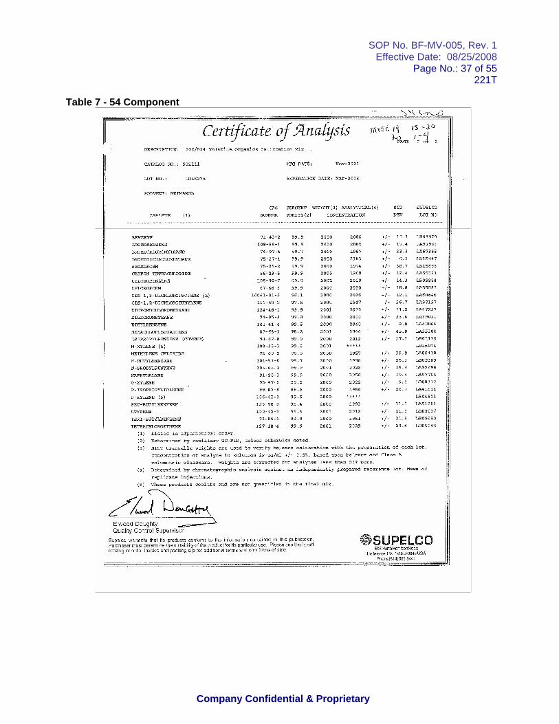
SOP No. BF-MV-005, Rev. 1Effective Date: 08/25/2008
Page No.: 37 of 55221T
Company Confidential & Proprietary
Table 7 - 54 Component

SOP No. BF-MV-005, Rev. 1Effective Date: 08/25/2008
Page No.: 38 of 55221T
Company Confidential & Proprietary

SOP No. BF-MV-005, Rev. 1Effective Date: 08/25/2008
Page No.: 39 of 55221T
Company Confidential & Proprietary
Table 8. 8260 + Mix

SOP No. BF-MV-005, Rev. 1Effective Date: 08/25/2008
Page No.: 40 of 55221T
Company Confidential & Proprietary

SOP No. BF-MV-005, Rev. 1Effective Date: 08/25/2008
Page No.: 41 of 55221T
Company Confidential & Proprietary

SOP No. BF-MV-005, Rev. 1Effective Date: 08/25/2008
Page No.: 42 of 55221T
Company Confidential & Proprietary
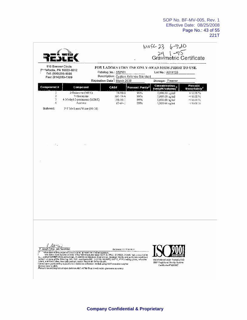
SOP No. BF-MV-005, Rev. 1Effective Date: 08/25/2008
Page No.: 43 of 55221T
Company Confidential & Proprietary

SOP No. BF-MV-005, Rev. 1Effective Date: 08/25/2008
Page No.: 44 of 55221T
Company Confidential & Proprietary
Table 9. Second Source

SOP No. BF-MV-005, Rev. 1Effective Date: 08/25/2008
Page No.: 45 of 55221T
Company Confidential & Proprietary

SOP No. BF-MV-005, Rev. 1Effective Date: 08/25/2008
Page No.: 46 of 55221T
Company Confidential & Proprietary

SOP No. BF-MV-005, Rev. 1Effective Date: 08/25/2008
Page No.: 47 of 55221T
Company Confidential & Proprietary
Table10. 8260+ Second Source

SOP No. BF-MV-005, Rev. 1Effective Date: 08/25/2008
Page No.: 48 of 55221T
Company Confidential & Proprietary

SOP No. BF-MV-005, Rev. 1Effective Date: 08/25/2008
Page No.: 49 of 55221T
Company Confidential & Proprietary

SOP No. BF-MV-005, Rev. 1Effective Date: 08/25/2008
Page No.: 50 of 55221T
Company Confidential & Proprietary

SOP No. BF-MV-005, Rev. 1Effective Date: 08/25/2008
Page No.: 51 of 55221T
Company Confidential & Proprietary
Table 11. 8260 Add

SOP No. BF-MV-005, Rev. 1Effective Date: 08/25/2008
Page No.: 52 of 55221T
Company Confidential & Proprietary

SOP No. BF-MV-005, Rev. 1Effective Date: 08/25/2008
Page No.: 53 of 55221T
Company Confidential & Proprietary
Table 12. BFB; IS & SS

SOP No. BF-MV-005, Rev. 1Effective Date: 08/25/2008
Page No.: 54 of 55221T
Company Confidential & Proprietary

SOP No. BF-MV-005, Rev. 1Effective Date: 08/25/2008
Page No.: 55 of 55221T
Company Confidential & Proprietary

Controlled Copy on Grey Paper, Do Not Duplicate TO15-1Page 1
Centek Laboratories, LLC Centek No.: TS-80 Laboratory Division Regulation: EPA TO15
Laboratory SOP Revision No. 1 Last Update: 02/2006 Volatile Organic Compounds By Gas Chromatography / Mass Spectroscopy and Cyro-focusing Approved: ___________________________ Russell J Pellegrino,
Technical Director ___________________________ Nick Scala, Quality Assurance Officer ___________________________ Russ Pellegrino, VOC Manager
1.0 PURPOSE 1.1 This SOP describes the procedure to determine whole air samples that are collected in a canister. VOC’s are cryofocused on a glass trap, then concentrated on a Tenax trap and finally refocused. The sample is then injected into a GC column, and passed to an MS detector for identification and quantification. The compounds determined by this method are listed in Table 1. 1.2 This procedure may be used for the following matrices and regulations: Matrix Regulation Air EPA
2.0 RESPONSIBILITIES
2.1 All GC/MS analysts performing this method are required to read and understand the method as written in the Compendium of methods for the Determination of Toxic Organic Compounds in Ambient Air TO-15 and are required to meet all QC requirements before attempting analysis of samples.
2.2 The section supervisor is required to read and understand the method as written but is also responsible for the
training and continued education of technicians performing this method.
2.3 The section supervisor is required to review reports and packages to ensure that all data are valid prior to client receipt.
3 .0 DEFINITIONS
3.1 GC/MS: Gas Chromatography/Mass Spectroscopy

Controlled Copy on Grey Paper, Do Not Duplicate TO15-1Page 2
3.2 Capillary: Analytical column with an internal diameter less than or equal to 0.34 mm
3.3 EICP: Extracted ion current profile: Each compound contains a quantitation ion that is singled out and displayed
as a peak
3.4 LIMS: Laboratory Information Management System
3.5 PQL: Practical Quantitation Limit
3.6 MDL: Method Detection Limit
3.7 IDL: Instrument Detection Limit
3.8 AMU: Atomic Mass Unit
3.9 VOA: Volatile Organic Compounds
3.10 RSD: Relative Standard Deviation
3.11 RRF: Relative Standard Deviation
3.12 NIST: National Institute of Science and Technology
3.13 CRQL: Contract Required Quantitation Limit
3.14 QAPP: Quality Assurance Project Plan
3.15 LCS: Laboratory Control Sample
4.0 METHOD SUMMARY 4.1 Whole air samples that are collected in a specially prepared canister. VOC’s are cryofocused on a glass
trap, then concentrated on a sorent trap and finally refocused on a third trap 4.2 The volatile compounds are introduced in to the GC/MS by injecting the sample extract into the Gas
Chromatograph (GC) with a narrow-bore fused-silica capillary column. The GC column is temperature programmed to separate the analytes, which are then detected with the MS connected to the GC.
4.3 The analytes eluted from the capillary column are introduced into the MS via auto injection. The
identification of target analytes is accomplished by comparing their mass spectra with the electron impact spectra of authentic standards. Quantitation is accomplished by comparing the response of a major (quantitative) ion relative to an internal standard using a five-point calibration curve.
5.0 SAFETY
5.1 Most volatile compounds are considered hazardous. Always wear gloves and a lab coat when handling stocks and solutions.
5.2 Safety glasses with side shields are required whenever you are in the laboratory. 5.3 It is very important that special precaution be used when working with liquid nitrogen. The holding
tanks are very heavy and the liquid nitrogen will cause burns. 6.0 INTERFERENCES
6.1 Raw GC/MS data from all samples and blanks must be evaluated for interference. Determine if the source of interference is in the preparation of the samples and take corrective action to eliminate the problem.

Controlled Copy on Grey Paper, Do Not Duplicate TO15-1Page 3
6.2 Contamination by carryover can occur whenever high-concentration and low-concentration samples are
sequentially analyzed. Whenever an unusually concentrated sample is analyzed, it should be followed by the analysis of an instrument blank to check for cross-contamination.
7.0 APPARATUS AND MATERIALS
7.1 Instrument 6890N Series GC in conjunction with 5973N mass spectrometer capable of scanning from 35 to 300 amu every 1-second or less, using 70 volts (nominal) electron energy.
7.2 Entech 7100 Preconcentrator with an Entec7032L auto sampler capable of cryofocusing and concentrating
samples using three separate modules. 7.2 Analytical Chromatography columns: 0.34mm ID x 60 M length and 1.4 um film thickness silicone-coated
capillary column- DB-5 VRX by J & W Scientific or equivalent. 7.3 GC/MS Interface - GC to MS interface that gives acceptable calibration points at 50 ppbv per injection for
each compound of interest and achieves acceptable tuning performance criteria may be used. 7.4 Data System – The computer system used is the HP Chem Station G1701DA system with Revision
D.00.01 software package. This system is interfaced to the mass spectrometer. The system has continuous acquisition and storage on machine- readable media of all mass spectra obtained throughout the duration of the chromatographic program. The system has software that can search any GC/MS data file for ions of a specific mass and that can plot such ion abundance versus time or scan number. This type of plot is defined as an Extracted Ion Current Profile. The software allows integration of the abundance in any EICP between specified times or scan number limits. NBS95K version Mass Spectral Library is being used.
8.0 CHEMICALS AND REAGENTS 8.1 Helium @ 99.9999% purity
8.2 Liquid nitrogen (see section 5.3)
8.3 Stock standards 8.3.1 Stock standard solutions can be prepared from pure standard materials or purchased as certified
solutions. 8.3.2 Stock standard solutions must be stored at room temperature, or as recommended by the
manufacturer. 8.3.3 Stock standard solutions must be replaced after 1 year, or sooner if comparison with check
standards indicates a problem. 8.4 Internal standard solutions
8.4.1 The recommended internal standards are Bromochloromethane, 1,4-Dichlorobenzene and Chlorobenzene.
8.4.2 Each 100cc of sample extract undergoing analysis and the calibration standards must be spiked with
50ppbv of each internal standard and surrogate. 8.5 GC/MS Tuning standard 8.5.1 A air sample solution containing 50ppbv of Bromofluorobenzene (BFB) must be prepared. The
standard could also contain 50ppb each of internal standards.

Controlled Copy on Grey Paper, Do Not Duplicate TO15-1Page 4
8.5.2 The tuning standard may be– stored room temperature when not in use. When using premixed certified solutions, store according to the manufacturer’s documented holding time and storage temperature recommendations.
8.6 Intermediate (working) standard 8.6.1 The working standard is prepared at 100 ppbv and 25 ppbv. It is used to make calibration standards.
The working standard must contain all analytes of interest. Also a working standard is prepared at 50 ppbv containing internal standards and surrogate.
8.6.2 Working standard must be prepared every six months or sooner if comparisons with check
standards indicates a problem. 8.7 Calibration standards 8.7.1 A minimum of five calibration standards must be prepared at five different concentrations. One of
the calibration standards must correspond to a sample concentration at or below that necessary to meet the data quality objectives of the project. The remaining standards must correspond to the range of concentrations found in the actual samples.
8.7.2 See Table 1 for targets, surrogates, internal standards and the concentrations of the calibration
standards. 8.7.3 Internal standards and surrogate is added to all calibration standards. 8.8 Internal Standards and Surrogate 8.8.1 Internal standard and surrogates are added to all calibration standards. See Table 1 for
concentration. 8.8.2 The internal standard and surrogate must be prepared every six months or sooner if comparison
with a check standard indicates a problem. 8.8.3 The internal standard and surrogate must be stored at room temperature. 9.0 SAMPLE COLLECTION, PRESERVATION AND HANDLING
9.1 Whole air samples are to be collected in 400cc “mini”-canister and kept at room temperature. Samples must be extracted within 14 days of collection.
9.2 Whole air samples can also be collected in Tedlar bags and kept at room temperature. Samples must be
extracted within 72 hours of collection. 9.4 Program specific holding time requirements if any, must take precedence over the above-mentioned
guidelines. 9.5 Samples, extracts and standards must be stored at separate locations to avoid cross-contamination.
10.0 PROCEDURE 10.1 Sample preparation 10.1.1 Once the samples have been collected and brought to room temperature. A pressure gauge is
connected to the canister inlet. This will indicate the amount of sample that was collected. If amount is less the 100cc a volume of nitrogen has to be added. This volume has to be recorded for a dilution.
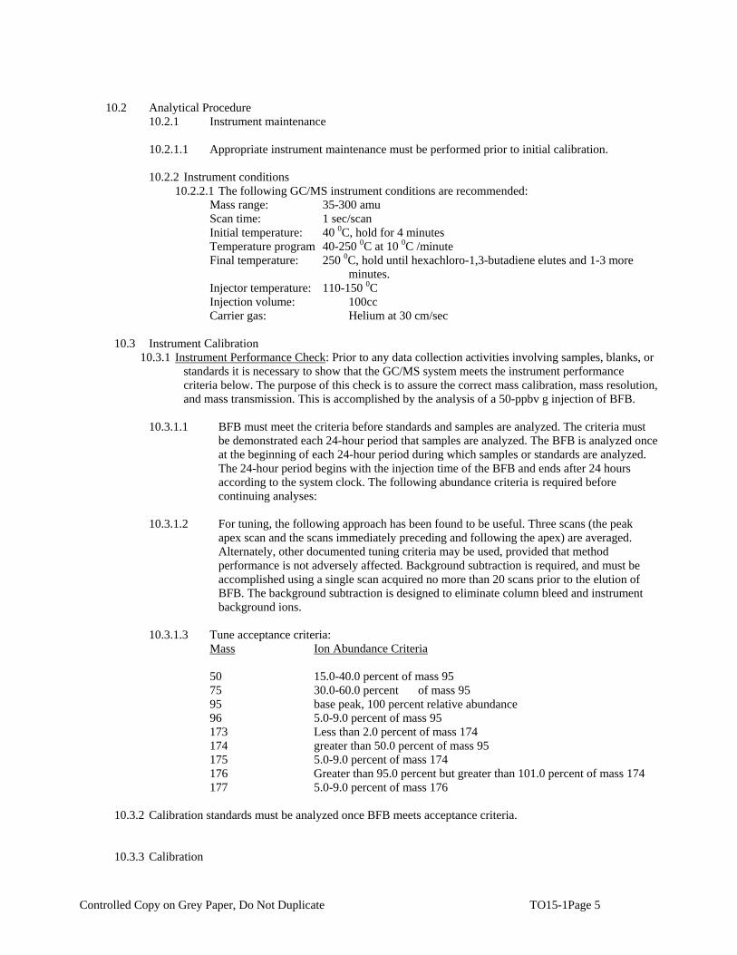
Controlled Copy on Grey Paper, Do Not Duplicate TO15-1Page 5
10.2 Analytical Procedure 10.2.1 Instrument maintenance
10.2.1.1 Appropriate instrument maintenance must be performed prior to initial calibration.
10.2.2 Instrument conditions 10.2.2.1 The following GC/MS instrument conditions are recommended:
Mass range: 35-300 amu Scan time: 1 sec/scan Initial temperature: 40 0C, hold for 4 minutes Temperature program 40-250 0C at 10 0C /minute Final temperature: 250 0C, hold until hexachloro-1,3-butadiene elutes and 1-3 more
minutes. Injector temperature: 110-150 0C Injection volume: 100cc Carrier gas: Helium at 30 cm/sec
10.3 Instrument Calibration 10.3.1 Instrument Performance Check: Prior to any data collection activities involving samples, blanks, or
standards it is necessary to show that the GC/MS system meets the instrument performance criteria below. The purpose of this check is to assure the correct mass calibration, mass resolution, and mass transmission. This is accomplished by the analysis of a 50-ppbv g injection of BFB.
10.3.1.1 BFB must meet the criteria before standards and samples are analyzed. The criteria must
be demonstrated each 24-hour period that samples are analyzed. The BFB is analyzed once at the beginning of each 24-hour period during which samples or standards are analyzed. The 24-hour period begins with the injection time of the BFB and ends after 24 hours according to the system clock. The following abundance criteria is required before continuing analyses:
10.3.1.2 For tuning, the following approach has been found to be useful. Three scans (the peak
apex scan and the scans immediately preceding and following the apex) are averaged. Alternately, other documented tuning criteria may be used, provided that method performance is not adversely affected. Background subtraction is required, and must be accomplished using a single scan acquired no more than 20 scans prior to the elution of BFB. The background subtraction is designed to eliminate column bleed and instrument background ions.
10.3.1.3 Tune acceptance criteria: Mass Ion Abundance Criteria 50 15.0-40.0 percent of mass 95 75 30.0-60.0 percent of mass 95 95 base peak, 100 percent relative abundance 96 5.0-9.0 percent of mass 95 173 Less than 2.0 percent of mass 174 174 greater than 50.0 percent of mass 95 175 5.0-9.0 percent of mass 174 176 Greater than 95.0 percent but greater than 101.0 percent of mass 174 177 5.0-9.0 percent of mass 176 10.3.2 Calibration standards must be analyzed once BFB meets acceptance criteria. 10.3.3 Calibration

Controlled Copy on Grey Paper, Do Not Duplicate TO15-1Page 6
10.3.3.1 A 5-point calibration curve must be analyzed prior to sample analysis. Dilute the intermediate standard (100-ppbv) as necessary to obtain the concentrations of 5,25,50,75, and 100 ppbv. The internal standards must be added at 50 ppbv to each concentration level (see list below). Analyze each standard in increasing concentration order to determine the instrument sensitivity and linearity of the GC/MS response for the target compounds. Analyze the following from each working standard canister:
From the 100ppbv working standard canister: 100ppv standard…use 100cc 75 ppbv standard…use 75cc 50 ppbv standard…use 50cc From the 25ppbv working standard canister: 25ppv standard…use 100cc 5 ppbv standard…use 205cc
10.3.3.2 Label the calibration standards in the sequence as follows: ASTD100, STD 1 ASTD75, STD 1 ASTD50, STD 1 ASTD25, STD 1 ASTD5, STD 1
10.3.3.3 calculate the response factor for each compound using the following equation: RF = Ax * Cis Ais Cx Where: Ax = Area of the characteristic ion for the compound to measured (see Table 1 and 2). Ais = Area of the characteristic ion for the specific internal standard (see Table 2). Cis = Concentration of the internal standard (µg/ml). Cx = Concentration of the compound to be measured (µg/ml).
10.3.3.4 calculate the average RF for each analytes in the curve 10.3.3.5 calculate the % Relative Standard Deviation of RF values for the initial calibration using the
following equation: %RSD = Standard Deviation (n-1) * 100 mean RF
10.3.4 Calibration acceptance criteria
10.3.4.1 The BFB must meet the specified criteria
10.3.4.2 The %RSD is calculated and must be less than or equal to 30% for the CCC compounds. The %RSD of all other calibration compounds must be less than or equal to 100%. This criterion must be met for the initial calibration to be valid.

Controlled Copy on Grey Paper, Do Not Duplicate TO15-1Page 7
10.3.4.3 The System Performance Check Compounds (SPCCs) must meet minimum RF criteria specified in Table
3.
10.3.4.4 Evaluation of retention time: The relative retention time (RRT) of each target analytes in each calibration standard should agree within 0.06RRT units.
10.4 Calibration verification 10.4.1 Instrument Performance Check: Prior to any data collection activities involving samples, blanks,
or standards, analyze a 50-ppbv injection of BFB). BFB must meet same criteria as the initial calibration.
10.4.2 Calibration verification standard: Analyze a 50-ppbv-calibration standard at the beginning of each
12-hour working period (that passed the BFB tune criteria). Calculate the % Difference between the average response factor from the calibration curve and the response factor from the continuing standard using the equation below:
% Difference = |RRFi - RRFc| * 100 RRFi Where: RRFi = Average relative response factor from initial calibration. RRFc = Relative response factor from the current calibration check standard. The verification standard must meet % D criteria mentioned in Table 4. 10.4.2.1 Internal standard retention time: The retention times of the internal standards in the
calibration verification standards must be evaluated immediately after the run. The retention time of any internal standard should not change by more than 30 seconds from that in the mid-point standard level of the most recent initial calibration sequence. If the retention time shift is outside this limit, associated runs must be reanalyzed after meeting the criteria.
10.4.2.2 Internal standard response: The EICP area of any of the internal standards in the calibration
verification standard should not change by a factor of two (-50% to +100%) from that in the mid-point standard of the most recent initial calibration.
10.4.2.3 Manual Integration: Permits the analyst to integrate the peak(s) of interest manually. This is
to be applied when a peak of interest has not been integrated (ex. split peak) from baseline to baseline. In this case the analyst must be consistent in defining the baseline. All manual integration will be flagged with an “m” and will be initialed by the analyst. The spectra will be put in for all compounds of interest showing the manual integration.
10.5 Sample analysis 10.5.1 Once the instrument check and continuing standard have passed the analysis criteria, samples may
be analyzed. Label the samples in analytical sequence as follows: WGXXXXX-X,SBLKXXXX,matrix,dilution factor (Prep. Blank) WGXXXXX-X,SBLKXXXXCS,matrix,dilution factor (Check sample) L11111-X,ClientID,matrix,dilution factor (Sample) 10.5.2 Allow the sample extract to warm to room temperature. During the analysis, add 100cc ppbv of
internal standard to the 100cc extract obtained from the sample “mini”-canister. 10.5.3 Inject the sample into the GC/MS system using the same operating conditions that were used for
the calibration.

Controlled Copy on Grey Paper, Do Not Duplicate TO15-1Page 8
10.5.4 If the response of any quantitative ion exceeds the initial calibration range of the GC/MS system,
the sample extract must be diluted and reanalyzed.
10.6 Qualitative analysis 10.6.1 The qualitative identification of compounds is based on retention time and comparison of the
sample spectrum with characteristic ions in a reference mass spectrum. The characteristic ions from the reference mass spectrum are defined as the three ions of greatest relative intensity, or any ions over 30% relative intensity, if less than three such ions occur in the reference spectrum. The compounds are identified when the following criteria are met:
10.6.1.1 The intensities of the characteristic ions of a compound must maximize in the same scan or
within one scan of each other. 10.6.1.2 The RRT of the sample component is within ±0.04 RRT units of the RRT of the standard
component. 10.6.1.3 The relative intensities of the characteristic ions agree within 30 percent of the relative
intensities of these ions in the reference spectrum from the most recent calibration verification standard.
10.6.1.4 Structural isomers that produce very similar mass spectra should be identified as individual
isomers if they have sufficiently different GC retention times. Sufficient GC resolution is achieved if the height of the valley between two isomer peaks is less than 25 percent of the sum of the two peak heights. Otherwise, structural isomers are identified as isomeric pairs.
10.6.1.5 Identification is hampered when sample components are not resolved chromatographically
and produce mass spectra containing ions contributed by more than one analyte. When gas chromatographic peaks obviously represent more than one sample component appropriate selection of analyte spectra and background spectra is important. When analytes coelute the identification criteria can be met, but each analyte spectrum will contain extraneous ions contributed by the coeluting compound.
10.6.1.6 Manual Integration: Permits the analyst to integrate the peak(s) of interest manually. This is
to be applied when a peak of interest has not been integrated (ex. split peak) from baseline to baseline. In this case the analyst must be consistent in defining the baseline. All manual integration will be flagged with an “m” and will be initialed by the analyst. The spectra will be put in for all compounds of interest showing the manual integration.
10.6.2 For samples containing components not associated with the calibration standards, a library search
may be made for the purpose of tentative identification.
10.7 Quantitative identification 10.7.1 Once a compound has been identified, the quantitation of that compound is based on the
integrated abundance of the primary characteristic ion from the EICP. 10.7.2 The concentration of a compound in the extract is determined using the average response factor
from initial calibration. 10.7.3 Use the equations below to quantitate the appropriate matrix:
µg/L = (Ax)(Is)(Df) (Ais)(RRF)(Vi) Where: Ax = Area of the characteristic ion for the compound to be measured.

Controlled Copy on Grey Paper, Do Not Duplicate TO15-1Page 9
Ais = Area of the characteristic ion for the internal standard. Is = Amount of the internal standard injected in nanograms RRF = Average response factor (from initial cal.) for the compound being measured. Vo = Volume of water extracted in milliliters Vi = Volume of sample injected in milliliters Vt = Volume of concentrated extracted in microliters Df = Dilution factor
10.7.4 The GC/MS data system contains identification files (ID files) that automatically identify target compounds in standards and samples. Quantitation is performed using the internal standard method. The list of characteristic ions for each analyte is listed in Table 2. In all instances where the data system report has been edited or where manual integration or quantitation has been performed the GC/MS operator must identify edits or manual procedures by initialing and dating the changes made to the report. The data system flags a manual integration on the quantitation report using a "M" next to the area. Samples that contain target analytes above the linear range of the curve (+10 percent or 110 ppbv) must be diluted to put the analytes within the curve range. Flag the analytes that exceed the linear range in the qualifier section with an "E". Report the dilution analysis with the suffix "DL" where the sample name appears. If a dilution was initially performed and no target analytes are reported above the PQL, the sample must be reanalyzed at a more concentrated level.
10.8 Technical Acceptance Criteria for Sample analysis
10.8.1 The samples must be analyzed on a system meeting BFB, initial calibration and calibration verification criteria.
10.8.2 The samples must be extracted and analyzed within contract required holding times. 10.8.3 The sample must have an associated prep. blank meeting acceptance criteria. 10.8.4 All samples and blanks must have surrogate recovery within in-house control limits. No surrogate
recovery can be less than 10% 10.8.5 The relative retention time of each surrogate must be within ± 0.06 RRT units of its relative
retention time in the calibration verification standard. 10.8.6 The instrumental response (EICP area) for each of the internal standards must be within –50%
and +100% of the response of the internal standards in the most recent calibration verification standard.
10.8.7 The retention time shift for each of the internal standards must be within +0.5 minutes between
the sample and the most recent calibration verification standard. 10.8.8 The sample spectra quant ion must be within 30% of the most recent calibration verification
standard. 10.8.9 Concentration of all analytes must be within the calibration range determined from the initial
calibration.
10.9 Corrective Action 10.9.1 Corrective Action for sample analysis: The sample technical acceptance criteria must be met. The
samples that did not meet criteria reanalysis. 10.9.2 Corrective Action for surrogate recovery failure: Check calculations, check spike standards.
Reanalyze the samples that exceeded criteria. If the samples met criteria upon reanalysis, report the reanalysis only. If the sample produced similar results upon reextraction and reanalysis, the

Controlled Copy on Grey Paper, Do Not Duplicate TO15-1Page 10
problem may be matrix-related. Report both sets of analyses. Use ‘R’ qualifier for reanalysis. If the reanalysis of samples does not solve the problem, contact the project manager so the client may be notified.
10.9.3 Corrective Action for Internal Standard Response failures: If any of the internal standards
exceeded acceptance criteria, check calculations. Verify that the standard concentration is accurate, and that the instrument did not malfunction. Reanalyze the sample to see if the problem was matrix related. If the reanalysis met criteria, report the reanalysis only. If the reanalysis produced similar results, report both analyses. Use ‘R’ qualifier to identify reanalysis results.
10.9.4 Corrective action for surrogate RRT/Internal standard retention time: If the surrogates or internal
standards exceeded retention time criteria, follow the same guidelines used in Section 10.9.3
11.0 QUALITY CONTROL
11.1 Instrument performance must be evaluated to see if all BFB, initial calibration and calibration verification criteria requirements are met.
11.2 Method blanks
11.2.1 A Method blank is a volume of a clean reference matrix (nitrogen @ 99.9999% purity) carried through the entire analytical procedure. The volume of the method blank must be approximately equal to the volume of the associated samples. The purpose of the method blank is to determine the level of contamination associated with the preparation and analysis of samples.
11.2.2 Method blanks must be extracted with each batch of samples at a frequency of 1 for every
20 samples. 11.2.3 Method blanks must be analyzed under the same conditions as the samples. 11.2.4 Method blanks must contain no targets above CRQL. If the method blank does not meet this
criterion, affected samples must be reanalyzed. 11.2.5 If the surrogate recoveries in the method blank do not meet the control limits, reanalyze the
method blank. If the method blank does not meet criteria after reanalysis, reanalyze the associated samples.
11.3 Quality Control Check Sample. 11.3.1 A Check sample consists of an aliquot of a clean matrix similar to the sample matrix and of the
same weight or volume. The CS is spiked with the all the target analytes at mid-level of the calibration curve. The spiking standard should be from a source different from that of the calibration standards.
11.3.2 A CS must be analyzed with every 20 samples or more frequently. The recoveries must be within
the in-house control limits. If the recoveries fall outside control limits, the CS must be reanalyzed. If the recoveries are still outside control limits, affected samples should be reanalyzed.
11.4 Surrogate Recoveries
11.4.1 All samples, including quality control samples, are spiked with surrogates. The surrogate solution contains bromofluorobenzene at 50 ppbv.
11.4.2 All samples must meet the surrogate recovery criteria. If any samples exceed criteria, the sample
must be reanalyzed. If the reanalysis produces similar results, contact the project manager.

Controlled Copy on Grey Paper, Do Not Duplicate TO15-1Page 11
11.5 Control Limits 11.5.1 All surrogate recoveries, and check sample data must be entered on the LIMS. In-house control
limits must be calculated annually. Accuracy and precision data must be compared against the control limits.
11.6 Initial Demonstration of Proficiency (IDP)
11.6.1 IDP is established by generating data of acceptable accuracy and precision for target analytes for each preparative method and matrix by analyzing reference samples.
11.6.2 The reference samples are prepared from a spiking solution containing each analyte of interest.
The solution should be made from stock standards prepared independently from those used for calibration. The concentration of targets in the reference sample may be 10-50 times the MDL.
11.6.3 Prepare and analyze 4 replicates of the reference sample by the same procedure used for
analyzing actual samples. Calculate average recovery in ppbv and standard deviation of the recovery of each analyte of interest. The average recovery may fall in the range of 70-130%.
11.6.4 IDP procedure must be repeated whenever new staff is trained or significant changes in
preparative or analytical methods are made.
11.7 Method Detection Limit (MDL) 11.7.1 The Method Detection Limit (MDL) for this procedure is used to judge the significance of a
single measurement of a future sample. The MDL is the constituent that, when processed through the complete method, produces a signal with 99% probability that it is different from the blank. MDL is the minimum concentration of a substance that can be measured and reported with 99% confidence that the analyte concentration is greater than zero and is determined by the analysis of samples in a given matrix type containing the analyte.
11.7.2 MDLs are determined annually.
12.0 DOCUMENTATION
12.1 The raw data is archived via CD-ROM and is stored in a secured area. The raw data will be kept in the laboratory for 5 years.
12.2 Chain of custody forms, instrument maintenance log, standards prep log, analytical run log, corrective
action logs etc. must be filled out in a timely manner. 13.0 REFERENCES Compendium of Methods for the Determination of Toxic Organic Compounds in Ambient Air, Second Edition, January 1999

Controlled Copy on Grey Paper, Do Not Duplicate TO15-1Page 12
Table 1
Calibration standards for 5ppb level (Concentration in ppbV)
COMPOUND LV1 LV2 LV3 LV4 LV5 LV6
Propylene 5 10 25 50 75 100
Freon-12 5 10 25 50 75 100
Chloromethane 5 10 25 50 75 100
Fron-114 5 10 25 50 75 100
Vinyl Chloride 5 10 25 50 75 100
Bromomethane 5 10 25 50 75 100
Chloroethane 5 10 25 50 75 100
Vinyl Bromide 5 10 25 50 75 100
Freon-11 5 10 25 50 75 100
Isopropyl Alcohol 5 10 25 50 75 100
Acetone 5 10 25 50 75 100
1,1-Dichloroethane 5 10 25 50 75 100
Methylene Chloride 5 10 25 50 75 100
Freon-113 5 10 25 50 75 100
Allyl Chloride 5 10 25 50 75 100
Carbon Disulfide 5 10 25 50 75 100
Trans-1,2-Dichlorethene 5 10 25 50 75 100
Methyl Tert-Butyl Ether 5 10 25 50 75 100
1,1-Dichloroethane 5 10 25 50 75 100
Vinyl Acetate 5 10 25 50 75 100
Methyl Ethyl Ketone 5 10 25 50 75 100
Cis-1,2-Dichloroethylene 5 10 25 50 75 100
Hexane 5 10 25 50 75 100
Ethyl Acetate 5 10 25 50 75 100
Chloroform 5 10 25 50 75 100
Tetrahydrofuran 5 10 25 50 75 100
1,2-Dichloroethane 5 10 25 50 75 100
1,1,1-Trichloroethane 5 10 25 50 75 100
Cyclohexane 5 10 25 50 75 100

Controlled Copy on Grey Paper, Do Not Duplicate TO15-1Page 13
Carbon Tetrachloride 5 10 25 50 75 100
Benzene 5 10 25 50 75 100
1,4-Dioxane 5 10 25 50 75 100
2,2,4-Trimethylpentane 5 10 25 50 75 100
Heptane 5 10 25 50 75 100
1,2-Dichloropropane 5 10 25 50 75 100
Trichloroethylene 5 10 25 50 75 100
Bromodichloromethane 5 10 25 50 75 100
cis-1,3-Dichloropropene 5 10 25 50 75 100
Trans-1,3-Dichloropropene 5 10 25 50 75 100
1,1,2-Trichloroethane 5 10 25 50 75 100
Toluene 5 10 25 50 75 100
Dibromochloromethane 5 10 25 50 75 100
Methyl Isobutyl Ketone 5 10 25 50 75 100
Methyl Butyl Ketone 5 10 25 50 75 100
1,2-Dibromomethane 5 10 25 50 75 100
Tetrachloroethylene 5 10 25 50 75 100
Chlorobenzene 5 10 25 50 75 100
Ethylbenzene 5 10 25 50 75 100
Bromoform 5 10 25 50 75 100
Styrene 5 10 25 50 75 100
o-xylene 5 10 25 50 75 100
m -xylene 5 10 25 50 75 100
p-xylene 5 10 25 50 75 100
1,1,2,2-Tetrachloroethane 5 10 25 50 75 100
4-Ethyltoluene 5 10 25 50 75 100
1,3,5-Trimethylbenzene 5 10 25 50 75 100
1,2,4-Trimethylbenzene 5 10 25 50 75 100
1,3-Dichlorobenzene 5 10 25 50 75 100
Benzyl Chloride 5 10 25 50 75 100
1,4-Dichlorobenzene 5 10 25 50 75 100
1,2-Dichlorobenzene 5 10 25 50 75 100
1,2,4-Trichlorobenzene 5 10 25 50 75 100
Hexachloro-1,3-Butadiene 5 10 25 50 75 100

Controlled Copy on Grey Paper, Do Not Duplicate TO15-1Page 14
Bromofluorobenzene (surrogate)
50 50 50 50 50 50
*Bromochloromethane 50 50 50 50 50 50
*1,4-Difluorobenzene 50 50 50 50 50 50
*Chlorobenzene-d5 50 50 50 50 50 50 *Indicates internal standard

Controlled Copy on Grey Paper, Do Not Duplicate TO15-1Page 15
Table 1 Calibration standards for 1ug/M3 level
(Concentration in ppbV)
COMPOUND LV1 LV2 LV3 LV4 LV5 LV6 LV7
Propylene 0.15 0.30 0.50 0.75 1.0 1.5 2.0
Freon-12 0.15 0.30 0.50 0.75 1.0 1.5 2.0
Chloromethane 0.15 0.30 0.50 0.75 1.0 1.5 2.0
Fron-114 0.15 0.30 0.50 0.75 1.0 1.5 2.0
Vinyl Chloride 0.15 0.30 0.50 0.75 1.0 1.5 2.0
Bromomethane 0.15 0.30 0.50 0.75 1.0 1.5 2.0
Chloroethane 0.15 0.30 0.50 0.75 1.0 1.5 2.0
Vinyl Bromide 0.15 0.30 0.50 0.75 1.0 1.5 2.0
Freon-11 0.15 0.30 0.50 0.75 1.0 1.5 2.0
Isopropyl Alcohol 0.15 0.30 0.50 0.75 1.0 1.5 2.0
Acetone 0.15 0.30 0.50 0.75 1.0 1.5 2.0
1,1-Dichloroethane 0.15 0.30 0.50 0.75 1.0 1.5 2.0
Methylene Chloride 0.15 0.30 0.50 0.75 1.0 1.5 2.0
Freon-113 0.15 0.30 0.50 0.75 1.0 1.5 2.0
Allyl Chloride 0.15 0.30 0.50 0.75 1.0 1.5 2.0
Carbon Disulfide 0.15 0.30 0.50 0.75 1.0 1.5 2.0
Trans-1,2-Dichlorethene 0.15 0.30 0.50 0.75 1.0 1.5 2.0
Methyl Tert-Butyl Ether 0.15 0.30 0.50 0.75 1.0 1.5 2.0
1,1-Dichloroethane 0.15 0.30 0.50 0.75 1.0 1.5 2.0
Vinyl Acetate 0.15 0.30 0.50 0.75 1.0 1.5 2.0
Methyl Ethyl Ketone 0.15 0.30 0.50 0.75 1.0 1.5 2.0
Cis-1,2-Dichloroethylene 0.15 0.30 0.50 0.75 1.0 1.5 2.0
Hexane 0.15 0.30 0.50 0.75 1.0 1.5 2.0
Ethyl Acetate 0.15 0.30 0.50 0.75 1.0 1.5 2.0
Chloroform 0.15 0.30 0.50 0.75 1.0 1.5 2.0
Tetrahydrofuran 0.15 0.30 0.50 0.75 1.0 1.5 2.0
1,2-Dichloroethane 0.15 0.30 0.50 0.75 1.0 1.5 2.0
1,1,1-Trichloroethane 0.15 0.30 0.50 0.75 1.0 1.5 2.0
Cyclohexane 0.15 0.30 0.50 0.75 1.0 1.5 2.0
Carbon Tetrachloride 0.15 0.30 0.50 0.75 1.0 1.5 2.0

Controlled Copy on Grey Paper, Do Not Duplicate TO15-1Page 16
Benzene 0.15 0.30 0.50 0.75 1.0 1.5 2.0
1,4-Dioxane 0.15 0.30 0.50 0.75 1.0 1.5 2.0
2,2,4-Trimethylpentane 0.15 0.30 0.50 0.75 1.0 1.5 2.0
Heptane 0.15 0.30 0.50 0.75 1.0 1.5 2.0
1,2-Dichloropropane 0.15 0.30 0.50 0.75 1.0 1.5 2.0
Trichloroethylene 0.15 0.30 0.50 0.75 1.0 1.5 2.0
Bromodichloromethane 0.15 0.30 0.50 0.75 1.0 1.5 2.0
cis-1,3-Dichloropropene 0.15 0.30 0.50 0.75 1.0 1.5 2.0
Trans-1,3-Dichloropropene 0.15 0.30 0.50 0.75 1.0 1.5 2.0
1,1,2-Trichloroethane 0.15 0.30 0.50 0.75 1.0 1.5 2.0
Toluene 0.15 0.30 0.50 0.75 1.0 1.5 2.0
Dibromochloromethane 0.15 0.30 0.50 0.75 1.0 1.5 2.0
Methyl Isobutyl Ketone 0.15 0.30 0.50 0.75 1.0 1.5 2.0
Methyl Butyl Ketone 0.15 0.30 0.50 0.75 1.0 1.5 2.0
1,2-Dibromomethane 0.15 0.30 0.50 0.75 1.0 1.5 2.0
Tetrachloroethylene 0.15 0.30 0.50 0.75 1.0 1.5 2.0
Chlorobenzene 0.15 0.30 0.50 0.75 1.0 1.5 2.0
Ethylbenzene 0.15 0.30 0.50 0.75 1.0 1.5 2.0
Bromoform 0.15 0.30 0.50 0.75 1.0 1.5 2.0
Styrene 0.15 0.30 0.50 0.75 1.0 1.5 2.0
o-xylene 0.15 0.30 0.50 0.75 1.0 1.5 2.0
m -xylene 0.15 0.30 0.50 0.75 1.0 1.5 2.0
p-xylene 0.15 0.30 0.50 0.75 1.0 1.5 2.0
1,1,2,2-Tetrachloroethane 0.15 0.30 0.50 0.75 1.0 1.5 2.0
4-Ethyltoluene 0.15 0.30 0.50 0.75 1.0 1.5 2.0
1,3,5-Trimethylbenzene 0.15 0.30 0.50 0.75 1.0 1.5 2.0
1,2,4-Trimethylbenzene 0.15 0.30 0.50 0.75 1.0 1.5 2.0
1,3-Dichlorobenzene 0.15 0.30 0.50 0.75 1.0 1.5 2.0
Benzyl Chloride 0.15 0.30 0.50 0.75 1.0 1.5 2.0
1,4-Dichlorobenzene 0.15 0.30 0.50 0.75 1.0 1.5 2.0
1,2-Dichlorobenzene 0.15 0.30 0.50 0.75 1.0 1.5 2.0
1,2,4-Trichlorobenzene 0.15 0.30 0.50 0.75 1.0 1.5 2.0
Hexachloro-1,3-Butadiene 0.15 0.30 0.50 0.75 1.0 1.5 2.0
Bromofluorobenzene 0.15 0.30 0.50 0.75 1.0 1.5 2.0
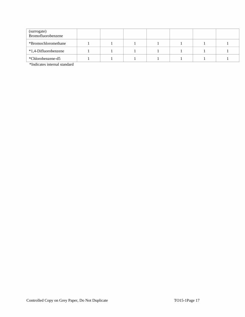
Controlled Copy on Grey Paper, Do Not Duplicate TO15-1Page 17
(surrogate) Bromofluorobenzene
*Bromochloromethane 1 1 1 1 1 1 1
*1,4-Difluorobenzene 1 1 1 1 1 1 1
*Chlorobenzene-d5 1 1 1 1 1 1 1 *Indicates internal standard

Controlled Copy on Grey Paper, Do Not Duplicate TO15-1Page 18
Table 2
Characteristic Ions, PQLs
COMPOUND EI
PRIMARY
EI
SECONDARY
EI
TERTIARY
PQL ppb
Propylene 41 39 5
Freon-12 85 87 5
Chloromethane 50 52 5
Freon-114 85 135 87 5
Vinyl Chloride 62 27 64 5
1,3-Butadiene 39 54 5
Bromomethane 94 96 5
Chloroethane 64 29 27 5
Vinyl Bromide 106 106 5
Freon-11 101 103 5
Isopropyl Alcohol 45 43 20
Acetone 43 58 5
1,1-Dichloroethene 96 96 63 5
Methylene Chloride 84 84 86 5
Freon-113 101 101 103 5
Allyl chloride 76 41 78 5
Carbon Disulfide 76 78 5
Trans-1,2-Dichloroethene 61 96 98 5
Methyl Tert-Butyl Ether 73 41 53 5
1,1-Dichloroethane 63 27 65 5
Vinyl Acetate 43 86 5
Methyl Ethyl Ketone 43 57 72 5
cis-1,2-Dichloroethylene 61 96 98 5
Hexane 57 41 43 5
Ethyl Acetate 43 45 61 5
Chloroform 83 85 47 5
Tetrahydrofuran 42 71 72 5

Controlled Copy on Grey Paper, Do Not Duplicate TO15-1Page 19
1,2-Dichloroethane 62 27 64 5
1,1,1-Trichloroethane 97 99 61 5
Cyclohexane 56 41 84 5
Carbon Tetrachloride 117 119 5
Benzene 78 77 50 5
1,4-Dioxane 88 58 20
2,2,4-Trimethylpentane 57 41 56 5
Heptane 43 57 71 5
1,2-Dichloropropane 63 41 62 5
Trichloroethylene 130 132 95 5
Bromodichloromethane 83 85 5
cis-1,3-Dichloropropene 75 39 77 5
Trans-1,3-Dichloropropene 75 39 77 5
1,1,2-Trichloroethane 97 83 61 5
Toluene 92 91 92 5
Dibromochloromethane 129 127 5
Methyl Isobutyl Ketone 43 57 58 20
Methyl Butyl Ketone 43 57 58 20
1,2-Dibromomethane 107 109 27 5
Tetrachloroethylene 164 164 131 5
Chlorobenzene 112 77 114 5
Ethylbenzene 91 106 5
Bromoform 173 175 5
Styrene 104 78 103 5
o-xylene 91 106 5
m–xylene 91 106 5
p –xylene 91 106 5
1,1,2,2-Tetrachloroethane 83 85 5
4-Ethyltoluene 105 120 5
1,3,5-Trimethylbenzene 105 120 5
1,2,4-Trimethylbenzene 105 120 5

Controlled Copy on Grey Paper, Do Not Duplicate TO15-1Page 20
1,3-Dichlorobenzene 146 148 111 5
Benzyl Chloride 91 126 5
1,4-Dichlorobenzene 146 148 111 5
1,2-Dichlorobenzene 146 148 111 5
1,2,4-Trichlorobenzene 180 182 184 5
Hexachloro-1,3-Butadiene 225 227 223 5
Bromofluorobenzene (surrogate) 95 -
*Bromochloromethane 128 -
*1,4-Difluorobenzene 114 -
*Chlorobenzene-d5 117 - *Indicates internal standard

Controlled Copy on Grey Paper, Do Not Duplicate TO15-1Page 21
Table 3
Volatile Internal Standards with Corresponding Analytes
Assigned for Quantitation __________________________________________________________________________ *Bromochloromethane *1,4-Difluorobenzene *Chlorobenzene-d5
Propylene 1,1,1-Trichloroethane Toluene
Freon-12 Cyclohexane Dibromochloromethane
Chloromethane Carbon Tetrachloride Methyl Isobutyl Ketone
Fron-114 Benzene Methyl Butyl Ketone
Vinyl Chloride 1,4-Dioxane 1,2-Dibromomethane
Bromomethane 2,2,4-Trimethylpentane Tetrachloroethylene
Chloroethane Heptane Chlorobenzene
Vinyl Bromide 1,2-Dichloropropane Ethylbenzene
Freon-11 Trichloroethylene Bromoform
Isopropyl Alcohol Bromodichloromethane Styrene
Acetone cis-1,3-Dichloropropene o-xylene
1,1-Dichloroethane Trans-1,3-Dichloropropene m -xylene
Methylene Chloride 1,1,2-Trichloroethane p-xylene
Freon-113 1,1,2,2-Tetrachloroethane
Allyl Chloride 4-Ethyltoluene
Carbon Disulfide 1,3,5-Trimethylbenzene
Trans-1,2-Dichlorethene 1,2,4-Trimethylbenzene
Methyl Tert-Butyl Ether 1,3-Dichlorobenzene
1,1-Dichloroethane Benzyl Chloride
Vinyl Acetate 1,4-Dichlorobenzene
Methyl Ethyl Ketone 1,2-Dichlorobenzene
Cis-1,2-Dichloroethylene 1,2,4-Trichlorobenzene
Hexane Hexachloro-1,3-Butadiene
Ethyl Acetate Bromofluorobenzene (surrogate)
Chloroform
Tetrahydrofuran
1,2-Dichloroethane
*Indicates internal standard

Controlled Copy on Grey Paper, Do Not Duplicate TO15-1Page 22

Attachment 2
Field Standard Operating Procedures

Imagine the result
Soil Drilling and Sample Collection
Rev. #: 1
Rev Date: March 3, 2009

g:\sop-library\reformatted sops 2008\hydrogeology sops\315199 - soil drilling and sample collection.doc
1SOP: Soil Drilling and Sample Collection
Rev. #: 1 | Rev Date: March 3, 2009
Approval Signatures
Prepared by: Date: 3/3/09
Reviewed by: Date: 3/3/09
(Technical Expert)

g:\sop-library\reformatted sops 2008\hydrogeology sops\315199 - soil drilling and sample collection.doc
2SOP: Soil Drilling and Sample Collection
Rev. #: 1 | Rev Date: March 3, 2009
I. Scope and Application
Overburden drilling is commonly performed using the hollow-stem auger drilling
method. Other drilling methods suitable for overburden drilling, which are sometimes
necessary due to site-specific geologic conditions, include: drive-and-wash, spun
casing, Rotasonic, dual-rotary (Barber Rig), and fluid/mud rotary. Direct-push
techniques (e.g., Geoprobe or cone penetrometer) may also be used. The drilling
method to be used at a given site will be selected based on site-specific consideration
of anticipated drilling depths, site or regional geologic knowledge, types of sampling to
be conducted, required sample quality and volume, and cost.
No oils or grease will be used on equipment introduced into the boring (e.g., drill rod,
casing, or sampling tools).
II. Personnel Qualifications
The Project Manager (a qualified geologist, environmental scientist, or engineer) will
identify the appropriate soil boring locations, depth and soil sample intervals in a
written plan.
Personnel responsible for overseeing drilling operations must have at least 16 hours
of prior training overseeing drilling activities with an experienced geologist,
environmental scientist, or engineer with at least 2 years of prior experience.
III. Equipment List
The following materials will be available during soil boring and sampling activities, as
required:
• Site Plan with proposed soil boring/well locations;
• Work Plan or Field Sampling Plan (FSP), and site Health and Safety Plan
(HASP);
• personal protective equipment (PPE), as required by the HASP;
• drilling equipment required by the American Society for Testing and Materials
(ASTM) D 1586, when performing split-spoon sampling;
• disposable plastic liners, when drilling with direct-push equipment;
• appropriate soil sampling equipment (e.g., stainless steel spatulas, knife);

g:\sop-library\reformatted sops 2008\hydrogeology sops\315199 - soil drilling and sample collection.doc
3SOP: Soil Drilling and Sample Collection
Rev. #: 1 | Rev Date: March 3, 2009
• equipment cleaning materials;
• appropriate sample containers and labels;
• chain-of-custody forms;
• insulated coolers with ice, when collecting samples requiring preservation by
chilling;
• photoionization detector (PID) or flame ionization detector (FID); and
• field notebook and/or personal digital assistant (PDA).
IV. Cautions
Prior to beginning field work, underground utilities in the vicinity of the drilling areas will
be identified by one of the following three actions (lines of evidence):
• Contact the State One Call
• Obtain a detailed site utility plan drawn to scale, preferably an “as-built” plan
• Conduct a detailed visual site inspection
In the event that one or more of the above lines of evidence cannot be conducted, or
if the accuracy of utility location is questionable, a minimum of one additional line of
evidence will be utilized as appropriate or suitable to the conditions. Examples of
additional lines of evidence include but are not limited to:
• Private utility locating service
• Research of state, county or municipal utility records and maps including
computer drawn maps or geographical information systems (GIS)
• Contact with the utility provider to obtain their utility location records
• Hand augering or digging
• Hydro-knife
• Air-knife

g:\sop-library\reformatted sops 2008\hydrogeology sops\315199 - soil drilling and sample collection.doc
4SOP: Soil Drilling and Sample Collection
Rev. #: 1 | Rev Date: March 3, 2009
• Radio Frequency Detector (RFD)
• Ground Penetrating Radar (GPR)
• Any other method that may give ample evidence of the presence or location of
subgrade utilities.
Overhead power lines also present risks and the following safe clearance must be maintained from them. Line VoltagePhase to phase (kV)
Power Line VoltagePhase to Phase (kV)
Minimum Safe Clearance(feet)
50 or below 10
Above 50 to 200 15
Above 200 to 350 20
Above 350 to 500 25
Above 500 to 750 35
Above 750 to 1,000 35
ANSI Standard B30.5-1994, 5-3.4.5
Avoid using drilling fluids or materials that could impact groundwater or soil quality, or
could be incompatible with the subsurface conditions.
Water used for drilling and sampling of soil or bedrock, decontamination of
drilling/sampling equipment, or grouting boreholes upon completion will be of a quality
acceptable for project objectives. Testing of water supply should be considered.
Specifications of materials used for backfilling borehole will be obtained, reviewed and
approved to meet project quality objectives.
V. Health and Safety Considerations
Field activities associated with overburden drilling and soil sampling will be performed
in accordance with a site-specific HASP, a copy of which will be present on site during
such activities.

g:\sop-library\reformatted sops 2008\hydrogeology sops\315199 - soil drilling and sample collection.doc
5SOP: Soil Drilling and Sample Collection
Rev. #: 1 | Rev Date: March 3, 2009
VI. Procedure
Drilling Procedures
The drilling contractor will be responsible for obtaining accurate and representative
samples; informing the supervising geologist of changes in drilling pressure; and
keeping a separate general log of soils encountered, including blow counts (i.e., the
number of blows from a soil sampling drive weight [140 pounds] required to drive the
split-barrel sampler in 6-inch increments). Records will also be kept of occurrences of
premature refusal due to boulders or construction materials that may have been used
as fill. Where a boring cannot be advanced to the desired depth, the boring will be
abandoned and an additional boring will be advanced at an adjacent location to obtain
the required sample. Where it is desirable to avoid leaving vertical connections
between depth intervals, the borehole will be sealed using cement and/or bentonite.
Multiple refusals may lead to a decision by the supervising geologist to abandon that
sampling location.
Soil Sampling Procedures
Samples of subsurface materials encountered while drilling soil borings will be
collected using one of the following methods:
• 2-inch split-barrel (split-spoon) sampler, if using the ASTM D 1586 - Standard
Test Method for Penetration Test and Split-Barrel Sampling of Soils
• Plastic internal soil sample sleeves if using direct-push drilling.
Soil samples are typically field screened with an FID or PID at sites where volatile
organic compounds are present in the subsurface. Field screening is performed using
one of the following methods:
• Upon opening the sampler, the soil is split open and the PID or FID probe is
placed in the opening and covered with a gloved hand. Such readings should be
obtained at several locations along the length of the sample
• A portion of the collected sample is placed in a jar, which is covered with
aluminum foil, sealed, and allowed to warm to room temperature. After warming,
the cover is removed, the foil is pieced with the FID or PID probe, and a reading
is obtained.

g:\sop-library\reformatted sops 2008\hydrogeology sops\315199 - soil drilling and sample collection.doc
6SOP: Soil Drilling and Sample Collection
Rev. #: 1 | Rev Date: March 3, 2009
Samples selected for laboratory analysis will be handled, packed, and shipped in
accordance with the procedures outlined in the Work Plan, FSP, or Chain-of-Custody,
Handling, Packing, and Shipping SOP.
A geologist will be onsite during drilling and sampling operations to describe each soil
sample on the soil boring log, including:
• percent recovery;
• structure and degree of sample disturbance;
• soil type;
• color;
• moisture condition;
• density;
• grain-size;
• consistency; and
• other observations, particularly relating to the presence of waste materials
Further details regarding geologic description of soil samples are presented in the Soil
Description SOP.
Particular care will be taken to fully describe any sheens observed, oil saturation,
staining, discoloration, evidence of chemical impacts, or unnatural materials.
VII. Waste Management
Water generated during cleaning procedures will be collected and contained onsite in
appropriate containers for future analysis and appropriate disposal.
PPE (such as gloves, disposable clothing, and other disposable equipment) resulting
from personnel cleaning procedures and soil sampling/handling activities will be
placed in plastic bags. These bags will be transferred into appropriately labeled 55-
gallon drums or a covered roll-off box for appropriate disposal.

g:\sop-library\reformatted sops 2008\hydrogeology sops\315199 - soil drilling and sample collection.doc
7SOP: Soil Drilling and Sample Collection
Rev. #: 1 | Rev Date: March 3, 2009
Soil materials will be placed in sealed 55-gallon steel drums or covered roll-off boxes
and stored in a secured area. Once full, the material will be analyzed to determine the
appropriate disposal method.
VIII. Data Recording and Management
The supervising geologist or scientist will be responsible for documenting drilling
events using a bound field notebook and/or PDA to record all relevant information in a
clear and concise format. The record of drilling events will include:
• start and finish dates of drilling;
• name and location of project;
• project number, client, and site location;
• sample number and depths;
• blow counts and recovery;
• depth to water;
• type of drilling method;
• drilling equipment specifications, including the diameter of drilling tools;
• documentation of any elevated organic vapor readings;
• names of drillers, inspectors, or other people onsite; and
• weather conditions.
IX. Quality Assurance
Equipment will be cleaned prior to use onsite, between each drilling location, and prior
to leaving the site. Drilling equipment and associated tools, including augers, drill
rods, sampling equipment, wrenches, and other equipment or tools that may have
come in contact with soils and/or waste materials will be cleaned with high-pressure
steam-cleaning equipment using a potable water source. The drilling equipment will
be cleaned in an area designated by the supervising engineer or geologist that is
located outside of the work zone. More elaborate cleaning procedures may be
g:\sop-library\reformatted sops 2008\hydrogeology sops\315199 - soil drilling and sample collection.doc
8SOP: Soil Drilling and Sample Collection
Rev. #: 1 | Rev Date: March 3, 2009
required for reusable soil samplers (split-spoons) when soil samples are obtained for
laboratory analysis of chemical constituents.
X. References
American Society of Testing and Materials (ASTM) D 1586 - Standard Test Method for
Penetration Test and Split-Barrel Sampling of Soils.

Imagine the result
Groundwater Sampling Using HydroPunch™
Rev. #: 01
Rev Date: March 3, 2009
g:\sop-library\reformatted sops 2008\hydrogeology sops\398782-groundwater sampling using hydropunch.doc
1SOP: Groundwater Sampling Using HydroPunch™
Rev. #: 01 | Rev Date: March 3, 2009
Approval Signatures
Prepared by: Date: 3/3/09
Reviewed by: Date: 3/3/09
(Technical Expert)
g:\sop-library\reformatted sops 2008\hydrogeology sops\398782-groundwater sampling using hydropunch.doc
2SOP: Groundwater Sampling Using HydroPunch™
Rev. #: 01 | Rev Date: March 3, 2009
I. Scope and Application
This document describes procedures for collecting discrete-depth groundwater
samples using the HydroPunch™ sampling device (QED Environmental Services,
Inc.), or equivalent, during drilling in unconsolidated materials. HydroPunch™ can be
used to collect a single sample from a selected depth, or multiple samples from a
single borehole to produce a profile of groundwater quality data versus depth. The
HydroPunch™ sampler is typically driven through open-ended drill casing or hollow-
stem augers.
HydroPunch™ consists of a drive point, a stainless steel screen section, a sample
reservoir integral within the tool body, and assorted O-rings and check valves to create
watertight seals within the various components. Two models of HydroPunch™ have
been developed, having slightly different designs and/or component parts as shown on
the attached HydroPunch™ schematic drawings. All components are made of
stainless steel, Teflon, or other relatively inert materials. The tool can be disassembled
easily for cleaning between samples.
Although this document refers to groundwater sample collection, HydroPunch™ is
also capable of obtaining samples of light or dense non-aqueous phase liquid (LNAPL
or DNAPL, respectively), if present at sufficient saturation and pressure head at the
depth of the ampler during deployment.
II. Personnel Qualifications
ARCADIS personnel directing, supervising, or leading groundwater sample collection
activities using HydroPunch™ should have a minimum of 2 years of previous
groundwater sampling experience and current health and safety training including 40-
hour HAZWOPER training, site supervisor training, site-specific training, first aid, and
CPR, as needed. Field personnel will also be compliant with client-specific training
requirements. In addition, ARCADIS field sampling personnel will be versed in the
relevant SOPs and posses the required skills and experience necessary to
successfully complete the desired field work.
III. Equipment List
The following materials are required for the collection of discrete-depth groundwater
samples using HydroPunch™.
• HydroPunch™ sampling device provided by drilling subcontractor

g:\sop-library\reformatted sops 2008\hydrogeology sops\398782-groundwater sampling using hydropunch.doc
3SOP: Groundwater Sampling Using HydroPunch™
Rev. #: 01 | Rev Date: March 3, 2009
• Drill casing or augers having an effective inside diameter of at least 1.25 inches (to be
provided by drilling subcontractor)
• Electronic water-level probe
• Groundwater sample containers provided by the testing laboratory
• Health and safety monitoring equipment and personal protective equipment
• Materials for decontamination of the sampler between samples
IV. Cautions
Because the HydroPunch™ sampler is a groundwater sampling device, it must be
used in saturated soils. Positive hydraulic head is required to fill the sampler, and the
sampler may fill slowly or not at all at depths just below the water table. HydroPunch™
I and HydroPunch™ II in the “groundwater mode” cannot be used at sampling depths
less than 5 feet below the water table. HydroPunch™ II in the “hydrocarbon mode” is
preferred for sampling at the water table.
Some types of geologic materials may not allow effective use of the HydroPunch™
sampler, even at significant depth below the water table. For example, extremely
dense soils or those containing cobbles or boulders may resist penetration of the
sampler, precluding its use. Low permeability soil such as silt and clay may not
produce groundwater at a sufficient rate to fill the HydroPunch™ sampler within a
practicable timeframe. For these types of situations, an alternative approach should be
considered, such as collecting a sample of saturated soil for analysis.
Groundwater samples collected using HydroPunch™ should be considered screening-
level data, suitable for obtaining a general understanding of groundwater quality and
selecting depths for monitoring well screens. Samples obtained using HydroPunch™
are commonly more turbid than those produced from installed, developed monitoring
wells. Higher turbidity could affect sample quality if samples are to be analyzed for
sorptive analytes such as polychlorinated biphenyls (PCBs), polycyclic aromatic
hydrocarbons (PAHs), pesticides or metals. For these types of analytes, unfiltered
HydroPunch™ samples could produce concentrations that are higher than those of
sediment-free aquifer water. Field or laboratory filtering of the samples obtained for
these types of constituents should be considered. For less-sorptive analytes (volatile
organic compounds, anions such as chloride, etc.), sample turbidity is unlikely to
adversely impact the direct usability of unfiltered samples.

g:\sop-library\reformatted sops 2008\hydrogeology sops\398782-groundwater sampling using hydropunch.doc
4SOP: Groundwater Sampling Using HydroPunch™
Rev. #: 01 | Rev Date: March 3, 2009
V. Health and Safety Considerations
• Sample collection will be performed using procedures consistent with the project Health
and Safety Plan.
• Appropriate personal protective equipment must be worn by ARCADIS field personnel
VI. Procedure
The following steps will be followed during the collection of discrete-depth groundwater
Samples using HydroPunch™:
1. Select the desired groundwater sampling depth.
2. The drilling subcontractor will advance the borehole to approximately 2 feet
above the depth from which a discrete water sample is to be obtained.
3. The drilling subcontractor will disassemble the HydroPunch™ sampling device
according to the manufacturer’s instructions to allow the sampler to be
decontaminated. The sampler should be completely disassembled, including
O-rings and/or check valves.
4. Decontaminate the sampler as appropriate for the range of groundwater
analytes to be sampled for, by washing with laboratory-grade detergent and
potable water wash, followed by solvent rinse (if sampling for organics) and
final rinse with deionized or distilled water. Check the condition of the O-rings
during each cleaning, and replace if necessary.
5. The drilling subcontractor will reassemble the decontaminated HydroPunch™
sampling device according to the manufacturer’s instructions and lower the
device to the bottom of the borehole.
6. The drilling subcontractor will push or drive the HydroPunch™ 5 feet below the
bottom of the casing or augers, then retract the sampler 3 feet upward.
Subsurface friction will retain the drive point in place, exposing the screen and
allowing groundwater to enter the sampling tool.
7. Allow sufficient time to allow the sampler to fill with water. Typically 30 minutes
is sufficient, except in low permeability materials.
8. Collect a groundwater sample by:

g:\sop-library\reformatted sops 2008\hydrogeology sops\398782-groundwater sampling using hydropunch.doc
5SOP: Groundwater Sampling Using HydroPunch™
Rev. #: 01 | Rev Date: March 3, 2009
• Retracting the sampler to ground surface – the drilling subcontractor will then open the
sampler allowing collection of the groundwater sample [if using the HydroPunch™ I or
else the HydroPunch™ II in groundwater mode (see Attachment A)]
• Lowering a bailer or a peristaltic or inertia pump tube through the rods and body of the
sampler, and retrieving the bailer or operating the pump to collect the groundwater
sample [if using the HydroPunch™ II in hydrocarbon mode (see Attachment A)]
9. Perform field filtering of samples if required by the work plan, FSP and/or QAPP.
10. Obtain field water quality measurements if required by the work plan, FSP
and/or QAPP.
11. Label the sample containers at the time of sampling with the following
information.
• Project name and number
• Sample location
• Sample number
• Date and time of collection
• Sampler initials
• Analyses required
12. Preserve, store, handle, and ship samples to the analytical laboratory under
chain of custody procedures as described in by the work plan, FSP and/or
QAPP.
VII. Waste Management
Investigation-derived waste will be managed as described in the Investigation-Derived
Waste Handling and Storage SOP.
VIII. Data Recording and Management
Borehole identification, sample depth, sample date and time will be recorded in the
field notebook, the boring log, and/or the personal digital assistant (PDA). The sample
will also be identified on an appropriate chain of custody form, as appropriate for
submittal to an analytical laboratory for analysis, if required. Consider digital
photography to record unusual field conditions or to document compliance.

g:\sop-library\reformatted sops 2008\hydrogeology sops\398782-groundwater sampling using hydropunch.doc
6SOP: Groundwater Sampling Using HydroPunch™
Rev. #: 01 | Rev Date: March 3, 2009
IX. Quality Assurance
The HydroPunch™ sampling device will be decontaminated as appropriate for the list
of analytical parameters for which the groundwater samples are collected.
X. References
No references are required to accompany this SOP.

g:\sop-library\reformatted sops 2008\hydrogeology sops\398782-groundwater sampling using hydropunch.doc
7SOP: Groundwater Sampling Using HydroPunch™
Rev. #: 01 | Rev Date: March 3, 2009

Imagine the result
Administering Helium Tracer Gasfor Leak Checks of Soil Gas or Sub-slab Sampling Points
Rev. #: 2
Rev Date: November 14, 2008

g:\sop-library\reformatted sops 2008\air sops\416199 - administering tracer gas (r2).doc
1SOP: Administering Helium Tracer Gas
Rev. #: 1 | Rev Date: May 20, 2008
Approval Signatures
Prepared by: Date: May 20, 2008
Mitch Wacksman
Reviewed by: Date: May 20, 2008
Robert Uppencamp
Approved by: Date: November 14, 2008
Christopher Lutes

g:\sop-library\reformatted sops 2008\air sops\416199 - administering tracer gas (r2).doc
2SOP: Administering Helium Tracer Gas
Rev. #: 1 | Rev Date: May 20, 2008
I. Scope and Application
When collecting subsurface vapor samples as part of a vapor intrusion evaluation, a
tracer gas serves as a quality assurance/quality control device to verify the integrity of
the vapor port seal. Without the use of a tracer, verification that a soil vapor sample
has not been diluted by ambient or indoor air is difficult.
This standard operating procedure (SOP) focuses on using helium as a tracer gas.
However, depending on the nature of the contaminants of concern, other compounds
can be used as a tracer including sulfur hexafluoride (SF6), butane and propane (or
other gases). In all cases, the protocol for using a tracer gas is consistent and includes
the following basic steps: (1) enrich the atmosphere in the immediate vicinity where
the port or sample tubing intersects the surface with the tracer gas; and (2) measure a
vapor sample from the sample tubing for the presence of high concentrations (> 10%)
of the tracer. A plastic pail, bucket, garbage can or even a plastic bag can serve to
keep the tracer gas in contact with the port during the testing.
There are two basic approaches to testing for the tracer gas:
1. Include the tracer gas in the list of target analytes reported by the laboratory; or
2. Use a portable monitoring device to analyze a sample of soil vapor for the tracer
prior to sampling for the compounds of concern. (Note that tracer gas samples
can be collected via syringe, Tedlar bag, etc. They need not be collected in
SUMMA® canisters or minicans.)
This SOP focuses on monitoring helium using a portable sampling device, although
helium can also be analyzed by the laboratory along with other volatile organic
compounds (VOCs). Real-time tracer sampling is generally preferred as the results
can be used to confirm the integrity of the port seals prior to formal sample collection.
During the initial stages of a subsurface vapor sampling program, tracer gas samples
should be collected at each of the sampling ports. If the results of the initial samples
indicate that the port seals are adequate, the Project Manager can consider reducing
the number of locations at which tracer gas samples are used. At a minimum, at least
10% of the subsequent samples should be supported with tracer gas analyses. When
using permanent soil vapor ports as part of a long-term monitoring program, the port
should be tested prior to the first sampling event. Tracer gas testing of subsequent
sampling events is not necessary unless conditions have changed at the site.

g:\sop-library\reformatted sops 2008\air sops\416199 - administering tracer gas (r2).doc
3SOP: Administering Helium Tracer Gas
Rev. #: 1 | Rev Date: May 20, 2008
II. Personnel Qualifications
ARCADIS field sampling personnel will have current health and safety training,
including 40-hour HAZWOPER training, site supervisor training, site-specific training,
first-aid, and cardiopulmonary resuscitation (CPR), as needed. ARCADIS field
sampling personnel will be well versed in the relevant SOPs and possess the required
skills and experience necessary to successfully complete the desired field work.
ARCADIS personnel responsible for leading the tracer gas testing must have previous
experience conducting similar tests.
III. Equipment List
The equipment required to conduct a helium tracer gas test is presented below:
• Appropriate PPE for site (as required by the Health and Safety Plan)
• Helium (laboratory grade)
• Regulator for helium tank
• Shroud (plastic bucket, garbage can, etc)
o The size of the shroud should be sufficient to fit over the sample port.
It is worth noting that using a smaller shroud obviously uses less
helium as well; this may be important when projects require a number
of helium tracer tests.
o The shroud will need to have three small holes in it. These holes will
include one on the top (to accommodate the sample tubing), and two
on the side (one for the helium detector probe, and one for the helium
line).
o The should ideally enclose the entire sampling train.
• Helium detector capable of measuring from 1 - 100% (Dielectric MGD-2002,
Mark Model 9522, or equivalent)
• Tedlar bags
• Seal material for shroud (rubber gasket, modeling clay, bentonite, etc).
Although the sealing material is not in direct contact with the sample if no leak
occurs, sealing materials with high levels of VOC emissions should be

g:\sop-library\reformatted sops 2008\air sops\416199 - administering tracer gas (r2).doc
4SOP: Administering Helium Tracer Gas
Rev. #: 1 | Rev Date: May 20, 2008
avoided, since they could easily contaminate a sample from a point in which a
trace leak occurs.
• Field notebook
IV. Procedure
The procedure used to conduct the helium tracer test should be specific to the shroud
being used and the methods of vapor port installation. The helium tracer test can be
conducted when using temporary or permanent sample point installs and from inside
or outside a facility. However when using the tracer gas within a indoor areas you
must provide adequate ventilation because helium is an asphyxiant.
1. Attach Teflon or nylon sample tubing to the sample point. This can be
accomplished utilizing a number of different methods depending on the sample
install (i.e., barbed fitting, Swage-Lok fitting, ball valve, etc.).
2. Place the shroud over the sample point and tubing.
3. Pull the tubing through hole in top of shroud. Seal opening with modeling clay.
4. Place weight on top of shroud to help maintain a good seal with the ground.
5. Insert helium tubing into hole in side of shroud, seal with modeling clay to
prevent leaks.
6. Fill shroud with helium. While filling shroud allow atmospheric air to escape
either by leaving a crack with the surface or by providing a release value on the
side of the shroud.
7. Use the helium detector to test level of helium gas from the bottom of the shroud
(where the sample tubing intersects the ground). Helium should be added until
the environment inside the shroud has > 60% helium.
8. Purge the sample point through the sample tubing into a Tedlar bag using a
hand held sampling pump. The sample pump should be operating at a rate of
approximately 100 ml/minute (the purge rate should typically not exceed the
sample collection rate). Test the air in the Tedlar bag for helium using portable
helium detector. If the port has been installed properly there should be zero
helium in purge air.
9. If > 10% helium is noted in purge air, add more clay or other material to the seal

g:\sop-library\reformatted sops 2008\air sops\416199 - administering tracer gas (r2).doc
5SOP: Administering Helium Tracer Gas
Rev. #: 1 | Rev Date: May 20, 2008
the sample port and repeat the testing procedure. If the seal cannot be fixed, re-
install sample point.
10. Monitor and record helium level in shroud before, during and after tracer test.
11. Monitor and record helium level in purge exhaust.
12. At successful completion of tracer test and sample point purging, the soil vapor
sample can be collected (if the helium shroud must be removed prior to sample
collection be mindful not disturb the sample tubing and any established seals).
V. Cautions
Helium is an asphyxiant! Be cautious with its use indoors!
Care should be taken not to pressurize shroud while introducing helium. If the shroud
is completely air tight and the helium is introduced quickly, the shroud can be over-
pressurized and helium can be pushed into the ground.
Because minor leakage around the port seal should not materially affect the usability
of the soil vapor sampling results, the mere presence of the tracer gas in the sample
should not be a cause for alarm. Consequently, portable field monitoring devices with
detection limits in the low ppm range are more than adequate for screening samples
for the tracer. If high concentrations (> 10%) of tracer gas are observed in a sample,
the port seal should be enhanced to reduce the infiltration of ambient air and the tracer
test readministered. If the problem cannot rectified, a new sample point should be
installed.
VI. Data Recording and Management
Measurements will be recorded in the field notebook at the time of measurement with
notations of the project name, sample date, sample start and finish time, sample
location, and the helium concentrations in both the shroud and the purge air before,
during, and after tracer testing. Any problems encountered should also be recorded in
the field notes.

g:\sop-library\reformatted sops 2008\air sops\416199 - administering tracer gas (r2).doc
6SOP: Administering Helium Tracer Gas
Rev. #: 1 | Rev Date: May 20, 2008
APPENDIX: Compressed Gases—Use and Storage
In general, a compressed gas is any material contained under pressure that is dissolved or
liquefied by compression or refrigeration. Compressed gas cylinders should be handled as high-
energy sources and therefore as potential explosives and projectiles. Prudent safety practices
should be followed when handling compressed gases since they expose workers to both
chemical and physical hazards.
Handling
• Safety glasses with side shields (or safety goggles) and other appropriate personalprotective equipment should be worn when working with compressed gases.
• Cylinders should be marked with a label that clearly identifies the contents.
• All cylinders should be checked for damage prior to use. Do not repair damaged cylinders or valves. Damaged or defective cylinders, valves, etc., should be taken out of use immediately and returned to the manufacturer/distributor for repair.
• All gas cylinders (full or empty) should be rigidly secured to a substantial structure at 2/3 height. Only two cylinders per restraint are allowed in the laboratory and only soldered link chains or belts with buckles are acceptable. Cylinder stands are also acceptable but not preferred.
• Handcarts shall be used when moving gas cylinders. Cylinders must be chained to thecarts.
• All cylinders must be fitted with safety valve covers before they are moved.
• Only three-wheeled or four-wheeled carts should be used to move cylinders.
• A pressure-regulating device shall be used at all times to control the flow of gas from the cylinder.
• The main cylinder valve shall be the only means by which gas flow is to be shut off. The correct position for the main valve is all the way on or all the way off.
• Cylinder valves should never be lubricated, modified, forced, or tampered with.
• After connecting a cylinder, check for leaks at connections. Periodically check for leaks while the cylinder is in use.
• Regulators and valves should be tightened firmly with the proper size wrench. Do not use adjustable wrenches or pliers because they may damage the nuts.
• Cylinders should not be placed near heat or where they can become part of an electrical circuit.
• Cylinders should not be exposed to temperatures above 50 °C (122 °F). Some rupture devices on cylinders will release at about 65 °C (149 °F). Some small cylinders, such as lecture bottles, are not fitted with rupture devices and may explode if exposed to high temperatures.

g:\sop-library\reformatted sops 2008\air sops\416199 - administering tracer gas (r2).doc
7SOP: Administering Helium Tracer Gas
Rev. #: 1 | Rev Date: May 20, 2008
• Rapid release of a compressed gas should be avoided because it will cause an unsecured gas hose to whip dangerously and also may build up enough static charge to ignite a flammable gas.
• Appropriate regulators should be used on each gas cylinder. Threads and the configuration of valve outlets are different for each family of gases to avoid improper use. Adaptors and homemade modifications are prohibited.
• Cylinders should never be bled completely empty. Leave a slight pressure to keep contaminants out.
Storage
• When not in use, cylinders should be stored with their main valve closed and the valve safety cap in place.
• Cylinders must be stored upright and not on their side. All cylinders should be secured.
• Cylinders awaiting use should be stored according to their hazard classes.
• Cylinders should not be located where objects may strike or fall on them.
• Cylinders should not be stored in damp areas or near salt, corrosive chemicals, chemical vapors, heat, or direct sunlight. Cylinders stored outside should be protected from the weather.
Special Precautions
Flammable Gases
• No more than two cylinders should be manifolded together; however several instruments or outlets are permitted for a single cylinder.
• Valves on flammable gas cylinders should be shut off when the laboratory is unattended and no experimental process is in progress.
• Flames involving a highly flammable gas should not be extinguished until the source of the gas has been safely shut off; otherwise it can reignite causing an explosion.
Acetylene Gas Cylinders
• Acetylene cylinders must always be stored upright. They contain acetone, which can discharge instead of or along with acetylene. Do not use an acetylene cylinder that has been stored or handled in a nonupright position until it has remained in an upright position for at least 30 minutes.
• A flame arrestor must protect the outlet line of an acetylene cylinder.
• Compatible tubing should be used to transport gaseous acetylene. Some tubing like copper forms explosive acetylides.
Lecture Bottles
g:\sop-library\reformatted sops 2008\air sops\416199 - administering tracer gas (r2).doc
8SOP: Administering Helium Tracer Gas
Rev. #: 1 | Rev Date: May 20, 2008
• All lecture bottles should be marked with a label that clearly identifies the contents.
• Lecture bottles should be stored according to their hazard classes.
• Lecture bottles that contain toxic gases should be stored in a ventilated cabinet.
• Lecture bottles should be stored in a secure place to eliminate them from rolling or falling.
• Lecture bottles should not be stored near corrosives, heat, direct sunlight, or in damp areas.
• To avoid costly disposal fees, lecture bottles should only be purchased from suppliers that will accept returned bottles (full or empty). Contact the supplier before purchasing lecture bottles to ensure that they have a return policy.
• Lecture bottles should be dated upon initial use. It is advised that bottles be sent back to the supplier after one year to avoid accumulation of old bottles.

Imagine the result
Sub-Slab Soil-Gas Sampling and Analysis Using USEPA Method TO-15 – Permanent Probe Approach
Rev. #: 1
Rev Date: November 14, 2008

g:\sop-library\reformatted sops 2008\air sops\425199 - sub-slab soil-gas sampling & analysis - method to-15-permanent probe approach.doc
1SOP: Sub-Slab Soil-Gas Sampling and Analysis Using USEPA Method TO-15 –
Permanent Probe Approach
Rev. #: 1 | Rev Date: November 14, 2008
Approval Signatures
Prepared by: Date: 11/14/08
Mitch Wacksman
Reviewed by: Date: 11/14/08
(Technical Expert) Christopher Lutes

g:\sop-library\reformatted sops 2008\air sops\425199 - sub-slab soil-gas sampling & analysis - method to-15-permanent probe approach.doc
2SOP: Sub-Slab Soil-Gas Sampling and Analysis Using USEPA Method TO-15 –
Permanent Probe Approach
Rev. #: 1 | Rev Date: November 14, 2008
I. Scope and Application
This document describes the procedures to install a sub-slab sampling port and collect
sub-slab soil-gas samples for the analysis of volatile organic compounds (VOCs) by
United States Environmental Protection Agency (USEPA) Method TO-15 (TO-15).
The TO-15 method uses a 6-liter SUMMA® passivated stainless steel canister. An
evacuated SUMMA canister (less than 28 inches of mercury [Hg]) will provide a
recoverable whole-gas sample of approximately 5.5 liters when allowed to fill to a
vacuum of 2 inches of Hg. The whole-air sample is then analyzed for VOCs using a
quadrupole or ion-trap gas chromatograph/mass spectrometer (GS/MS) system to
provide compound detection limits of 0.5 parts per billion volume (ppbv).
The following sections list the necessary equipment and detailed instructions for
installing sub-slab soil-gas probes and collecting soil-gas samples for VOC analysis.
II. Personnel Qualifications
ARCADIS field sampling personnel will have current health and safety training, including 40-hour
HAZWOPER training, site supervisor training, site-specific training, first-aid, and
cardiopulmonary resuscitation (CPR), as needed. ARCADIS field sampling personnel will be
well versed in the relevant standard operating procedures (SOPs) and possess the required
skills and experience necessary to successfully complete the desired field work. ARCADIS
personnel responsible for leading sub-slab soil-gas sample collection activities must have
previous sub-slab soil-gas sampling experience.
III. Equipment List
The equipment required to install a permanent sub-slab vapor probe is presented
below:
• Electric impact drill;
• 5/8-inch and 1-inch-diameter concrete drill bits for impact drill;
• Stainless steel vapor probe (typically 3/8-inch outside diameter [OD], 2- to 2.5-
inch long (length will ultimately depend on slab thickness), 1/8-inch inside
diameter [ID] pipe, stainless steel pipe nipples with 0.5-inch OD stainless steel
coupling, and recessed stainless steel plugs per DiGiulio et. al., 2003);
• Photoionization detector (PID);
• Teflon tubing; and

g:\sop-library\reformatted sops 2008\air sops\425199 - sub-slab soil-gas sampling & analysis - method to-15-permanent probe approach.doc
3SOP: Sub-Slab Soil-Gas Sampling and Analysis Using USEPA Method TO-15 –
Permanent Probe Approach
Rev. #: 1 | Rev Date: November 14, 2008
• Quick-setting hydraulic cement powder.
The equipment required for soil-gas sample collection is presented below:
• Stainless steel SUMMA® canisters (order at least one extra, if feasible);
• Flow controllers with in-line particulate filters and vacuum gauges; flow
controllers are pre-calibrated to specified sample duration (e.g., 30 minutes, 8
hours, 24 hours) or flow rate (e.g., 200 milliliters per minute [mL/min]); confirm
with the laboratory that the flow controller comes with an in-line particulate
filter and pressure gauge (order at least one extra, if feasible);
• 1/4-inch ID tubing (Teflon®, or similar);
• Twist-to-lock fittings;
• Stainless steel “T” fitting (if collecting duplicate [i.e., split] samples);
• Portable vacuum pump capable of producing very low flow rates (e.g., 100 to
200 mL/min) with vacuum gauge;
• Rotameter or an electric flow sensor if vacuum pump does not have a flow
gauge;
• Tracer gas source (e.g., helium);
• PID;
• Appropriate-sized open-end wrench (typically 9/16-inch and ½”);
• Chain-of-custody (COC) form;
• Sample collection log (attached); and
• Field notebook.
IV. Cautions
Sampling personnel should not handle hazardous substances (such as gasoline),
permanent marking pens, wear/apply fragrances, or smoke cigarettes/cigars before
and/or during the sampling event.

g:\sop-library\reformatted sops 2008\air sops\425199 - sub-slab soil-gas sampling & analysis - method to-15-permanent probe approach.doc
4SOP: Sub-Slab Soil-Gas Sampling and Analysis Using USEPA Method TO-15 –
Permanent Probe Approach
Rev. #: 1 | Rev Date: November 14, 2008
Care should also be taken to ensure that the flow controller is pre-calibrated to the
proper sample collection time (confirm with laboratory). Sample integrity is maintained
if the sampling event is shorter than the target duration, but sample integrity can be
compromised if the event is extended to the point that the canister reaches
atmospheric pressure.
Care must be taken to properly seal around the vapor probe at slab surface to prevent
leakage of atmosphere into the soil vapor probe during purging and sampling.
Temporary points are fit snug into the pre-drilled hole using Teflon® tape and a
hydrated bentonite seal at the surface. Permanent points are fit snug using quick-
setting hydraulic cement powder.
A Shipping Determination must be performed, by DOT-trained personnel, for all
environmental and geotechnical samples that are to be shipped, as well as some
types of environmental equipment/supplies that are to be shipped.
V. Health and Safety Considerations
Field sampling equipment must be carefully handled to minimize the potential for injury
and the spread of hazardous substances. For sub-slab vapor probe installation,
drilling with an electric concrete impact drill should be done only by personnel with
prior experience using such a piece of equipment.
VI. Procedure
Permanent Vapor Probe Installation
Permanent sub-slab soil vapor probes are installed using an electric drill and manual
placement of the probe. Drill a 1-inch-diameter hole, approximately 1-inch deep, in the
concrete and then use the 5/8-inch-diameter drill to advance the hole to approximately
3 inches below the base of the floor slab. The vapor probe is inserted into the hole
and grouted with a quick-setting hydraulic cement powder. The vapor probe is
equipped with a recessed threaded cap and stainless steel threaded fitting or
compression fitting to allow collection of a soil gas sample through the stainless steel
tubing. The vapor probe and tubing will be purged with a portable sampling pump
prior to collecting the soil gas sample.
1. Remove, only to the extent necessary, any covering on top of the slab (e.g.,
carpet).

g:\sop-library\reformatted sops 2008\air sops\425199 - sub-slab soil-gas sampling & analysis - method to-15-permanent probe approach.doc
5SOP: Sub-Slab Soil-Gas Sampling and Analysis Using USEPA Method TO-15 –
Permanent Probe Approach
Rev. #: 1 | Rev Date: November 14, 2008
2. Drill a 5/8-inch-diameter hole through the slab using the electric drill. (Optional:
Although not required, use a source of dust control/suppressant during drilling
operations.)
3. Advance the hole to approximately 3 inches beneath the bottom of the slab.
4. Overdrill the upper 1 inch of slab to a hole diameter of 1 inch.
5. Insert the vapor probe so that it sits flush with the top of the slab.
6. Use a quick-setting hydraulic cement to grout the probe in-place and allow the
grout to set.
7. Purge the soil vapor probe and tubing with a portable sampling pump prior to
collecting the soil-gas sample (see sample collection section below).
8. Proceed to soil-gas sample collection.
9. When sub-slab soil-gas sampling is complete, plug the soil vapor probe opening
with a stainless steel plug. Ensure that the probe is well sealed and will not pose
a tripping hazard
Sub-Slab Soil-Gas Sample Collection
Preparation of SUMMA®-Type Canister and Collection of Sample
1. Record the following information in the field notebook, if appropriate (contact the
local airport or other suitable information source [e.g., site-specific
measurements, weatherunderground.com] to obtain the information):
a. wind speed and direction;
b. ambient temperature;
c. barometric pressure; and
d. relative humidity.
2. Connect a short piece of Teflon tubing to the sub-slab sampling port using a
swage lock fitting.

g:\sop-library\reformatted sops 2008\air sops\425199 - sub-slab soil-gas sampling & analysis - method to-15-permanent probe approach.doc
6SOP: Sub-Slab Soil-Gas Sampling and Analysis Using USEPA Method TO-15 –
Permanent Probe Approach
Rev. #: 1 | Rev Date: November 14, 2008
3. Connect a portable vacuum pump to the sample tubing. Purge 1 to 2 (target
1.5) volumes of air from the vapor probe and sampling line using a portable
pump [purge volume = 1.5 Pi r2h] at a rate of approximately 100 mL/min.
Measure organic vapor levels with the PID. Lower flow rates maybe necessary if
the slab is built directly on clay to avoid excessive vacuum.
4. If necessary, check the seal established around the soil vapor probe by using a
tracer gas (e.g., helium) or other method established in the state guidance
documents. [Note: Some states (e.g., New York) may not require use of a
tracer gas in connection with sub-slab sampling. Refer to the Administering
Tracer Gas SOP, adapted from NYSDOH 2005, for how to use a tracer gas.]
5. Remove the brass on stainless steel plug from the SUMMA® canister and
connect the flow controller with in-line particulate filter and vacuum gauge to the
SUMMA® canister. Do not open the valve on the SUMMA® canister. Record
in the field notebook and on the COC form the flow controller number with the
appropriate SUMMA® canister number.
6. Connect the Teflon sample collection tubing to the flow controller and the
SUMMA® canister valve. Record in the field notebook the time sampling began
and the canister pressure.
7. Connect the other end of the polyethylene tubing to the sub-slab sampling port.
8. Open the SUMMA® canister valves. Record in the field notebook the time
sampling began and the canister pressure.
9. Take a photograph of the SUMMA® canister and surrounding area.
Termination of Sample Collection
1. Arrive at the SUMMA® canister location at least 10 to 15 minutes prior to the
end of the required sampling interval (e.g., 30 to 60 minutes).
2. Record the final vacuum pressure. Stop collecting the sample by closing the
SUMMA® canister valves. The canister should have a minimum amount of
vacuum (approximately 2 inches of Hg or slightly greater).
3. Record the date and local time (24-hour basis) of valve closing in the field
notebook, sample collection log (attached), and COC form.

g:\sop-library\reformatted sops 2008\air sops\425199 - sub-slab soil-gas sampling & analysis - method to-15-permanent probe approach.doc
7SOP: Sub-Slab Soil-Gas Sampling and Analysis Using USEPA Method TO-15 –
Permanent Probe Approach
Rev. #: 1 | Rev Date: November 14, 2008
4. Remove the particulate filter and flow controller from the SUMMA® canister, re-
install the brass plug on the canister fitting, and tighten with the appropriate
wrench.
5. Package the canister and flow controller in the shipping container supplied by
the laboratory for return shipment to the laboratory. The SUMMA® canister
does not require preservation with ice or refrigeration during shipment.
6. Complete the appropriate forms and sample labels as directed by the laboratory
(e.g., affix card with a string).
7. Complete the COC form and place the requisite copies in a shipping container.
Close the shipping container and affix a custody seal to the container closure.
Ship the container to the laboratory via overnight carrier (e.g., Federal Express)
for analysis.
VII. Waste Management
No specific waste management procedures are required.
VIII. Data Recording and Management
Measurements will be recorded in the field notebook at the time of measurement with
notations of the project name, sample date, sample start and finish time, sample
location (e.g., GPS coordinates, distance from permanent structure [e.g., two walls,
corner of room]), canister serial number, flow controller serial number, initial vacuum
reading, and final pressure reading. Field sampling logs and COC records will be
transmitted to the Project Manager.
IX. Quality Assurance
Soil-gas sample analysis will be performed using USEPA TO-15 methodology. This
method uses a quadrupole or ion-trap GC/MS with a capillary column to provide
optimum detection limits. The GC/MS system requires a 1-liter gas sample (which can
easily be recovered from a 6-liter canister) to provide a 0.5-ppbv detection limit. The
6-liter canister also provides several additional 1-liter samples in case subsequent re-
analyses or dilutions are required. This system also offers the advantage of the
GC/MS detector, which confirms the identity of detected compounds by evaluating
their mass spectra in either the SCAN or SIM mode.

g:\sop-library\reformatted sops 2008\air sops\425199 - sub-slab soil-gas sampling & analysis - method to-15-permanent probe approach.doc
8SOP: Sub-Slab Soil-Gas Sampling and Analysis Using USEPA Method TO-15 –
Permanent Probe Approach
Rev. #: 1 | Rev Date: November 14, 2008
X. References
DiGiulio et. al. 2003. Draft Standard Operating Procedure (SOP) for Installation of
Sub-Slab Vapor Probes and Sampling Using EPA TO-15 to Support Vapor Intrusion
Investigations. http://www.cdphe.state.co.us/hm/indoorair.pdf (Attachment C)
New York State Department of Health (NYSDOH). 2005. DRAFT “Guidance for
Evaluating Soil Vapor Intrusion in the State of New York” February 23, 2005.

g:\sop-library\reformatted sops 2008\air sops\425199 - sub-slab soil-gas sampling & analysis - method to-15-permanent probe approach.doc
1SOP: Sub-Slab Soil-Gas Sampling and Analysis Using USEPA Method TO-15 –
Permanent Probe Approach
Rev. #: 1 | Rev Date: November 14, 2008
Sub-Slab Sample Collection Log
Sample ID:
Client: Boring Equipment:
Project: Sealant:
Location: Tubing information:
Project #:Miscellaneous Equipment:
Samplers: Subcontractor:
Sample Point Location:Moisture Content of Sampling Zone (circle one):
Dry / Moist
Sampling Depth:Approximate Purge Volume and Method:
Time of Collection:
Instrument Readings:
Time
Canister Pressure(inches of
HG)
Temperature(F or C)
Relative Humidity
(%)
Air Speed(ft/min)
Pressure Differential(inches of
H20)
PID(ppm or
ppb)
SUMMA Canister Information:
Size (circle one): 1 L 6 L
Canister ID:
Flow Controller ID:
General Observations/Notes:
Approximating One-Well Volume (for purging): When using 1¼-inch “Dummy Point” and a 6-inch sampling interval,
sampling space will have a volume of approximately 150 mL. Each foot of ¼-inch tubing will have a volume of approximately 10 mL.
Please record current weather information including wind speed and direction, ambient temperature, barometric pressure and relative humidity via a suitable information source (e.g., weatherunderground.com).

Imagine the result
Sub-Slab Soil-Gas Sampling Using Temporary Sampling Ports
Rev. #: 2
Rev Date: November 14, 2008

g:\sop-library\reformatted sops 2008\air sops\427199 - sub-slab soil-gas sampling - temporary ports.doc
1SOP: Sub-Slab Soil-Gas Sampling Using Temporary Sampling Ports
Rev. #: 2 | Rev Date: November 14, 2008
Approval Signatures
Prepared by: Date: May 20, 2008
Mitch Wacksman
Reviewed by: Date: May 20, 2008
Robert Uppencamp
Approved by: Date: November 14, 2008
Christopher Lutes

g:\sop-library\reformatted sops 2008\air sops\427199 - sub-slab soil-gas sampling - temporary ports.doc
2SOP: Sub-Slab Soil-Gas Sampling Using Temporary Sampling Ports
Rev. #: 2 | Rev Date: November 14, 2008
I. Scope and Application
This document describes the procedures to install a sub-slab sampling port and collect
sub-slab soil gas samples for the analysis of volatile organic compounds (VOCs) by
United States Environmental Protection Agency (USEPA) Method TO-15. In particular,
this standard operating procedure (SOP) describes the installation and collection of a
sub-slab soil gas sample using only hand tools and does not involve installation using
a geoprobe or post run tubing (PRT) system. Method TO-15 uses a 6-liter or 1-liter
SUMMA® passivated stainless steel canister. An evacuated SUMMA canister (less
than 28 inches of mercury [Hg]) will provide a recoverable whole-gas sample that is
then analyzed for VOCs using a quadrupole or ion-trap gas chromatograph/mass
spectrometer (GC/MS) system to provide compound detection limits of 0.5 parts per
billion volume (ppbv) or lower.
The following sections list the necessary equipment and detailed instructions for
installing sub-slab soil gas ports and collecting soil-gas samples.
II. Personnel Qualifications
ARCADIS field sampling personnel will have current health and safety training,
including 40-hour Hazardous Waste Operations and Emergency Response
(HAZWOPER) training. Site supervisor training, site-specific training, first-aid, and
cardiopulmonary resuscitation (CPR) may be appropriate at some sites. ARCADIS
field sampling personnel will be well versed in the relevant SOPs and possess the
required skills and experience necessary to successfully complete the desired field
work. ARCADIS personnel responsible for leading sub-slab soil-gas sample collection
activities must have previous sub-slab soil-gas sampling experience.
III. Equipment List
The equipment required to install and collect a temporary sub-slab vapor port is listed
below. Any modifications to account for project- or regulatory-specific requirements
should be noted in the accompanying work plan.
• Equipment for installing a sub-slab soil gas point
o Appropriate PPE (as required by the Health and Safety Plan);
o Hammer drill (Hilti, Bosch Hammer, or equilivant);
o 1/2 inch-diameter concrete drill bit;

g:\sop-library\reformatted sops 2008\air sops\427199 - sub-slab soil-gas sampling - temporary ports.doc
3SOP: Sub-Slab Soil-Gas Sampling Using Temporary Sampling Ports
Rev. #: 2 | Rev Date: November 14, 2008
o Hand tools including open-end wrench (typically 9/16-inch);
o 1/4-inch OD tubing (Teflon, nylon, or Teflon-lined); Note that Nylaflow
tubing has a somewhat higher background level of BTEX and much
poorer recovery of tirchlorobenzene and naphthalene then Teflon, so
should not be used on sites where these compounds are a concern
(Hayes, 2006).
o Teflon® tape;
o Hydrated bentonite, VOC-free modeling clay or wax to seal drill hole;
o Extension cords; and
o Shop vac.
• Equipment for collecting a sub-slab soil gas point
o Stainless steel SUMMA® canisters (6-liter, 1-liter or smaller; order at
least one extra, if feasible);
o Flow controllers with in-line particulate filters and vacuum gauges;
flow controllers are pre-calibrated to specified sample duration (e.g.,
30 minutes, 8 hours, 24 hours) or flow rate (e.g., 200 milliliters per
minute [mL/min]); confirm with the laboratory that the flow controller
comes with an in-line particulate filter and pressure gauge (order at
least one extra, if feasible); Flow rate should be selected based on
expected subslab material/soil type (see below).
o Swage-Lok fittings;
o Stainless steel Swage-Lok “T” fitting (if collecting duplicate [i.e., split]
samples);
o Portable vacuum pump capable of producing very low flow rates (e.g.,
100 to 200 milliliters per minute [mL/min]) (recommend SKC-PCXR8);
vacuum pump should also be equipped with a vacuum guage
o Rotameter or an electric flow sensor if vacuum pump does not have
and accurate flow gauge;

g:\sop-library\reformatted sops 2008\air sops\427199 - sub-slab soil-gas sampling - temporary ports.doc
4SOP: Sub-Slab Soil-Gas Sampling Using Temporary Sampling Ports
Rev. #: 2 | Rev Date: November 14, 2008
o Tracer gas testing supplies if applicable (refer to SOP for
“Administering Tracer Gas”);
o Photo Ionization Detector (PID) with a lamp of 11.7 eV; detectable to
ppb range (optional);
o Tedlar bag to collect purge air;
o Portable weather meter, if appropriate (temperature, barometric
pressure, humidity, etc);
o Quick setting grout or sika flex to seal abandoned holes;
o Chain-of-custody (COC) form;
o Sample collection log (attached); and
o Field notebook.
IV. Cautions
The following cautions and field tips should be reviewed and considered prior to
installing or collecting a sub-slab soil gas sample.
• When drilling sample collection holes be mindful of any utilities that may be in
the area. If the driller is concerned about a particular location, consult the
project manager about moving it to another location. Don’t be hesitant to use
your Stop Work Authority, if something doesn’t seem right stop and remedy
the situation.
• Sampling personnel should not handle hazardous substances (such as
gasoline), permanent marking pens, wear/apply fragrances, or smoke
cigarettes/cigars before and/or during the sampling event.
• Ensure that the flow controller is pre-calibrated to the proper sample collection
time by checking the regulators (check tags, markings, shipping forms) sent
by the laboratory (if there is any doubt, confirm with laboratory).
• Care must be taken to properly seal around the vapor port at slab surface to
prevent leakage of atmosphere into the soil vapor port during purging and
sampling. Temporary points should be fit snug into the pre-drilled hole using

g:\sop-library\reformatted sops 2008\air sops\427199 - sub-slab soil-gas sampling - temporary ports.doc
5SOP: Sub-Slab Soil-Gas Sampling Using Temporary Sampling Ports
Rev. #: 2 | Rev Date: November 14, 2008
Teflon® tape or modeling clay and a seal hydrated bentonite, clay or wax at
the surface.
• It is important to record the canister pressure, start and stop times and ID on a
proper field sampling form. Often Summa canisters are collected with a 24
hour averaging period. You should observe and record the time/pressure at
the start, and then again one or two hours after starting the sample collection.
It is a good practice to lightly tap the pressure gauge with your finger before
reading it to make sure it isn’t stuck. If the canister is running correctly for a 24
hour period then the vacuum will have decreased slightly after an hour or two
(for example from 29” to 27”). Consult your project manager (PM), risk
assessor or air sampling expert by phone if the Summa canister does not
appear to be working properly.
• Ensure that there is still measureable vacuum in the Summa after sampling.
Sample integrity is maintained if the sampling event is shorter than the target
duration, but sample integrity can be compromised if the event is extended to
the point that the canister reaches atmospheric pressure. Excessive vacuum
remaining in the canister can also result in elevated reporting limits.
• Many times the gauges sent from labs have large offset errors, or they stick.
For the most precise pressure readings consider using a separate, more
sensitive, device to do checks at the beginning and end of the sampling
period. If this is used it must be tested beforehand to confirm that it does not
introduce contaminants to the can during pressure checks
• When sampling carefully consider elevation. If your site is over 2,000’ above
sea level or the difference in elevation between your site and your lab is more
than 2,000’ then pressure effects will be significant. If you take your samples
at a high elevation they will contain less air for a given ending pressure
reading. High elevation samples analyzed at low elevation will result in more
dilution at the lab, which could affect reporting limits. Conversely low elevation
samples when received at high elevation may appear to not have much
vacuum left in them http://www.uigi.com/Atmos_pressure.html.
• If possible, have equipment shipped a day or two before the sampling date so
that all materials can be checked.
• Requesting extra canisters from the laboratory should also be considered to
ensure that you have enough equipment on site in case of an equipment
failure.
g:\sop-library\reformatted sops 2008\air sops\427199 - sub-slab soil-gas sampling - temporary ports.doc
6SOP: Sub-Slab Soil-Gas Sampling Using Temporary Sampling Ports
Rev. #: 2 | Rev Date: November 14, 2008
A Shipping Determination must be performed, by DOT-trained personnel, for all
environmental and geotechnical samples that are to be shipped, as well as some
types of environmental equipment/supplies that are to be shipped.

g:\sop-library\reformatted sops 2008\air sops\427199 - sub-slab soil-gas sampling - temporary ports.doc
7SOP: Sub-Slab Soil-Gas Sampling Using Temporary Sampling Ports
Rev. #: 2 | Rev Date: November 14, 2008
V. Health and Safety Considerations
Field sampling equipment must be carefully handled to minimize the potential for injury
and the spread of hazardous substances. Review appropriate health and safety plan
(HASP) and job safety analysis (JSA) prior to beginning work to be aware of all
potential hazards associated with the job site and the specific installation. A full utility
mark-out should be done prior to any drilling activities. If sample points are in
questionable locations consult the project manager about moving sample point. For
sub-slab vapor port installation, drilling with a hammer drill should be done only by
personnel with prior experience using such a piece of equipment. New staff should
be trained and supervised by experienced drill users.
VI. Procedure
Temporary sub-slab soil vapor ports are installed using equipment and procedures
that allows the point to be installed quickly and abandoned after an initial sample is
collected. These procedures are not recommended if the point is to be sampled more
than once. Under those conditions refer to ARCADIS’ SOP for permanent sub-slab soil
gas installations.
Sub-slab Soil Gas Point Installation
1. A utility mark-out of the pertinent areas should be accomplished prior to any
drilling activities.
2. Remove, only to the extent necessary, any covering on top of the slab (e.g.,
carpet).
3. Drill a 1/2 inch diameter hole through the concrete slab using the electric drill.
4. Advance the drill bit approximately 3 inches into the sub-slab material to
create an open cavity. Note if possible from the drill cuttings any evidence for
the types of materials in the immediate subslab – i.e. moisture barriers, sand,
gravel, shrinkage gap?
5. Using a shop-vac, clean any material that may have fallen into and around the
hole.
6. Re-drill the hole to ensure it remains clear. This can also be accomplished
using a piece of steel rod, sample tubing, or even a piece of heavy wire (coat
hanger).

g:\sop-library\reformatted sops 2008\air sops\427199 - sub-slab soil-gas sampling - temporary ports.doc
8SOP: Sub-Slab Soil-Gas Sampling Using Temporary Sampling Ports
Rev. #: 2 | Rev Date: November 14, 2008
7. Wrap the tubing with Teflon® tape or modeling clay, to the extent necessary,
for a snug fit of tubing and hole.
8. Insert the tubing approximately 3 inches into the sub-slab material.
9. Prepare a hydrated bentonite mixture and apply bentonite at slab surface
around the tubing. Instead of hydrated bentonite, either VOC free modeling
clay or wax may be used to seal the tubing into the slab.
10. Purge the soil vapor port and tubing with a portable sampling pump. Purge
approximately three volumes of air from the vapor port and sampling line
using a portable pump [purge volume = 1.5 Pi r2h] at a rate of approximately
100 to 200 mL/min. All purge air should be collected into a tedlar bag to
ensure VOCs are not released into any interior spaces. This flow rate should
be suitable for a variety of gravel, silt and sand conditions but will not be
achievable in some clays without excessive vacuum. Excessive vacuums
should be avoided. The cutoff value for vacuum however differs in the
sources however from 10” of water column (ITRC 2007) to 136” of water
column or 10” of mercury
(http://www.dtsc.ca.gov/lawsregspolicies/policies/SiteCleanup/upload/SMBR_
ADV_activesoilgasinvst.pdf). A detailed discussion of the achievable flow
rates in various permeability materials can be found in Nicholson 2007.
Related issues of contaminant partitioning are summarized in ASTM D5314-
92. Passive sampling approaches can be considered as an alternative for
clay soils. Measure organic vapor levels with the PID, as appropriate.
11. Proceed to soil gas sample collection.
Sub-Slab Soil Gas Sample Collection
Once the temporary sample port is installed, the following procedure should be used to
collect the sample in the Summa canister.
1. Remove the brass plug from the SUMMA® canister and connect the flow
controller with in-line particulate filter and vacuum gauge to the SUMMA®
canister. Do not open the valve on the SUMMA® canister.
2. Connect the sample collection tubing from the sample port to the flow
controller and the SUMMA® canister valve.

g:\sop-library\reformatted sops 2008\air sops\427199 - sub-slab soil-gas sampling - temporary ports.doc
9SOP: Sub-Slab Soil-Gas Sampling Using Temporary Sampling Ports
Rev. #: 2 | Rev Date: November 14, 2008
3. Attach duplicate or other QA/QC samples as required by applicable
regulations and guidance. Use a Swahe-Lok t-fitting supplied by the laboratory
to connect two canisters to the sample port tubing.
4. If necessary, check the seal around the soil vapor port by using a tracer gas
(e.g., helium) or other method established in the appropriate guidance
document (see helium tracer gas SOP).
5. Open the SUMMA® canister valve to initiate sample collection.
6. Record the following information on the sample log, field notebook, and or
COC:
• Starting sample time;
• Initial canister pressure;
• Weather conditions including wind speed and direction; ambient
outside and inside temperatures; barometric pressure; and relative
humidity; and
• Sample canister serial number and flow controller numbers.
7. If appropriate, take a photograph of the SUMMA® canister and surrounding
area.
8. Depending on the sample collection duration it is generally advisable to wait
for the canister to fill or to check on the canister at least once during the
sample collection period. If the vacuum gauge does not appear to be working
properly (see Section IV), then it may be appropriate to terminate the sample
collection early and use another Summa canister for sample collection.
Termination of Sample Collection
Arrive at the SUMMA® canister location at least 10 to 15 minutes prior to the end of
the required sampling interval in order to have sufficient time to terminate the sample
collection.
1. Record the final vacuum pressure. Stop collecting the sample by closing the
SUMMA® canister valves. The canister should have a minimum amount of
vacuum (approximately 2 inches of Hg or slightly greater).

g:\sop-library\reformatted sops 2008\air sops\427199 - sub-slab soil-gas sampling - temporary ports.doc
10SOP: Sub-Slab Soil-Gas Sampling Using Temporary Sampling Ports
Rev. #: 2 | Rev Date: November 14, 2008
2. Record the date and time of valve closing in the sample collection log
(attached) and COC form.
3. Remove the particulate filter and flow controller from the SUMMA® canister,
re-install the brass plug on the canister fitting, and tighten with the appropriate
wrench.
4. When the sub-slab soil gas sampling is complete, remove the tubing and
grout the hole in the slab with quick-setting hydraulic cement powder, Sika-
Flex, or other material similar to the slab. This step must be done carefully to
ensure that the abandoned sampling point does not become a preferential
flow pathway.
5. Replace the surface covering (e.g., carpet) to the extent practicable. Sample
collection location should be returned to pre-sampling conditions.
6. Package the canister and flow controller in the shipping container supplied by
the laboratory for return shipment to the laboratory. The SUMMA® canister
does not require preservation with ice or refrigeration during shipment.
7. Complete the appropriate forms and sample labels as directed by the
laboratory (e.g., affix card with a string).
8. Complete the COC form and place the requisite copies in a shipping
container. Close the shipping container and affix a custody seal to the
container closure. Ship the container to the laboratory via overnight carrier
(e.g., Federal Express) for analysis.
9. Before shipping ensure that the valve is off and that Swagelok plug is on
firmly.
VII. Waste Management
The volume of waste materials generated by these activities should be minimal.
Personal protective equipment, such as gloves and other disposable equipment (i.e.,
tubing) should be collected by field personnel for proper disposal.
VIII. Data Recording and Management
Information collected in the field should be recorded in the field notebook as well as
written on the field sampling log and COC, as appropriate. The field notebook and
sampling log must include the project name, sample date, sample start and finish time,

g:\sop-library\reformatted sops 2008\air sops\427199 - sub-slab soil-gas sampling - temporary ports.doc
11SOP: Sub-Slab Soil-Gas Sampling Using Temporary Sampling Ports
Rev. #: 2 | Rev Date: November 14, 2008
sample location (e.g., global positioning system [GPS] coordinates, distance from
permanent structure [e.g., two walls, corner of room]), canister serial number, flow
controller serial number, initial vacuum reading, and final pressure reading. Field
sampling logs and COC records will be transmitted to the PM.
IX. Quality Assurance
Duplicate samples should be collected in the field as a quality assurance step.
Generally, duplicates are taken of 10% of samples, but project specific requirements
should take precedence.
Soil-gas sample analysis will generally be performed using USEPA TO-15
methodology or a project specific constituent list. Method TO-15 uses a quadrupole or
ion-trap GC/MS with a capillary column to provide optimum detection limits (typically
0.5-ppbv for most VOCs).
X. References
ASTM – “Standard Guide for Soil Gas Monitoring in the Vadose Zone”, D5314-92.
Hayes, H. C., D.J. Benton and N. Khan “Impact of Sampling media on Soil Gas
Measurements” Presented with short paper at AWMA Vapor Intrucion
Conference January 2006, Philadelphia PA.
ITRC “Vapor Intrusion Pathway: A Practical Guide”, January 2007, Appendix F:
“regulators Checklist for Reviewing Soil Gas Data”
Nicholson, P, D. Bertrand and T. McAlary. “Soil Gas Sampling in Low-Permeability
Materials” Presented at AWMA Specialty Conference on Vapor Intrusion,
Providence RI, Sept 2007.

Imagine the result
Ambient Air Sampling and Analysis Using USEPA Method TO-15
Rev. #: 1
Rev Date: March 13, 2009

g:\sop-library\reformatted sops 2008\air sops\755199 - ambient air sampling & analysis - method to-15.doc
1SOP: Ambient Air Sampling and Analysis Using USEPA Method TO-15
Rev. #: 1 | Rev Date: March 13, 2009
Approval Signatures
Prepared by: Date: 3/13/09
Nadine Weinberg
Reviewed by: Date: 3/13/09
Christopher Lutes (Technical Expert)

g:\sop-library\reformatted sops 2008\air sops\755199 - ambient air sampling & analysis - method to-15.doc
2SOP: Ambient Air Sampling and Analysis Using USEPA Method TO-15
Rev. #: 1 | Rev Date: March 13, 2009
I. Scope and Application
This standard operating procedure (SOP) describes the procedures to collect ambient
air samples for the analysis of volatile organic compounds (VOCs) using United States
Environmental Protection Agency (USEPA) Method TO-15 (TO-15). The TO-15
method uses a 6-liter SUMMA® passivated stainless steel canister. An evacuated
SUMMA® canister (<28 inches of mercury [Hg]) will provide a recoverable whole-gas
sample of approximately 5.5 liters when allowed to fill to a vacuum of 2-7 inches of Hg.
The whole-air sample is then analyzed for VOCs using a quadrupole or ion-trap gas
chromatograph/mass spectrometer (GS/MS) system to provide compound detection
limits of 0.5 parts per billion volume (ppbv).
The following sections list the necessary equipment and detailed instructions for
placing the sampling device and collecting ambient air samples for VOC analysis.
II. Personnel Qualifications
ARCADIS field sampling personnel will have current health and safety training,
including 40-hour HAZWOPER training, site supervisor training, site-specific training,
first aid, and cardiopulmonary resuscitation (CPR), as needed. ARCADIS field
sampling personnel will be well versed in the relevant SOPs and possess the required
skills and experience necessary to successfully complete the desired field work.
ARCADIS personnel responsible for leading ambient air sample collection activities
must have previous ambient air sampling experience.
III. Equipment List
The equipment required for ambient air sample collection is presented below:
• 6-liter, stainless steel SUMMA® canisters (order at least one extra, if feasible);
• Flow controllers with in-line particulate filters and vacuum gauges (flow
controllers are pre-calibrated by the laboratory to a specified sample duration
[e.g., 8-hour]). Confirm with lab that flow controller comes with in-line
particulate filter and pressure gauge (order an extra set for each extra
SUMMA® canister, if feasible);
• Appropriate-sized open-end wrench (typically 9/16-inch);
• Chain-of-custody (COC) form;
• Field notebook;

g:\sop-library\reformatted sops 2008\air sops\755199 - ambient air sampling & analysis - method to-15.doc
3SOP: Ambient Air Sampling and Analysis Using USEPA Method TO-15
Rev. #: 1 | Rev Date: March 13, 2009
• Sample collection log (attached);
• Camera;
• Lock and chain; and
• Ladder or similar to hold canister above the ground surface (optional).
IV. Cautions
Care must be taken to minimize the potential for introducing interferences during the
sampling event. As such, care must be taken to keep the canister away from public
roadways to prevent collection of automobile source pollutants (unless this is the
objective of the study). Care must also be taken to keep the canister away from heavy
pedestrian traffic areas (e.g., main entranceways, walkways). If the canister is not to
be overseen for the entire sample duration, precautions should be taken to maintain
the security of the sample (e.g., do not place in areas regularly accessed by the public,
fasten the sampling device to a secure object using lock and chain, label the canister
to indicate it is part of a scientific project, place the canister in secure housing that
does not disrupt the integrity/validity of the sampling event). Sampling personnel
should not handle hazardous substances (such as gasoline), permanent marking
pens, wear/apply fragrances, or smoke cigarettes/cigars before and/or during the
sampling event.
Care should also be taken to ensure that the flow controller is pre-calibrated to the
proper sample collection time (confirm with laboratory). Sample integrity is maintained
if the sampling event is shorter than the target duration, but sample integrity can be
compromised if the event is extended to the point that the canister reaches
atmospheric pressure.
A Shipping Determination must be performed, by DOT-trained personnel, for all
environmental and geotechnical samples that are to be shipped, as well as some
types of environmental equipment/supplies that are to be shipped.
V. Health and Safety Considerations
Field sampling equipment must be carefully handled to minimize the potential for injury
and the spread of hazardous substances.
VI. Procedure
Preparation of SUMMA®-Type Canister and Collection of Sample
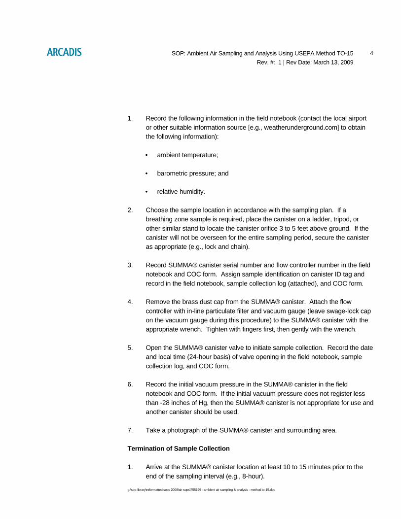
g:\sop-library\reformatted sops 2008\air sops\755199 - ambient air sampling & analysis - method to-15.doc
4SOP: Ambient Air Sampling and Analysis Using USEPA Method TO-15
Rev. #: 1 | Rev Date: March 13, 2009
1. Record the following information in the field notebook (contact the local airport
or other suitable information source [e.g., weatherunderground.com] to obtain
the following information):
• ambient temperature;
• barometric pressure; and
• relative humidity.
2. Choose the sample location in accordance with the sampling plan. If a
breathing zone sample is required, place the canister on a ladder, tripod, or
other similar stand to locate the canister orifice 3 to 5 feet above ground. If the
canister will not be overseen for the entire sampling period, secure the canister
as appropriate (e.g., lock and chain).
3. Record SUMMA® canister serial number and flow controller number in the field
notebook and COC form. Assign sample identification on canister ID tag and
record in the field notebook, sample collection log (attached), and COC form.
4. Remove the brass dust cap from the SUMMA® canister. Attach the flow
controller with in-line particulate filter and vacuum gauge (leave swage-lock cap
on the vacuum gauge during this procedure) to the SUMMA® canister with the
appropriate wrench. Tighten with fingers first, then gently with the wrench.
5. Open the SUMMA® canister valve to initiate sample collection. Record the date
and local time (24-hour basis) of valve opening in the field notebook, sample
collection log, and COC form.
6. Record the initial vacuum pressure in the SUMMA® canister in the field
notebook and COC form. If the initial vacuum pressure does not register less
than -28 inches of Hg, then the SUMMA® canister is not appropriate for use and
another canister should be used.
7. Take a photograph of the SUMMA® canister and surrounding area.
Termination of Sample Collection
1. Arrive at the SUMMA® canister location at least 10 to 15 minutes prior to the
end of the sampling interval (e.g., 8-hour).

g:\sop-library\reformatted sops 2008\air sops\755199 - ambient air sampling & analysis - method to-15.doc
5SOP: Ambient Air Sampling and Analysis Using USEPA Method TO-15
Rev. #: 1 | Rev Date: March 13, 2009
2. Stop collecting the sample when the canister vacuum reaches approximately 2-
7 inches of Hg (leaving some vacuum in the canister provides a way to verify if
the canister leaks before it reaches the laboratory) or when the desired sample
time has elapsed.
3. Record the final vacuum pressure. Stop collecting the sample by closing the
SUMMA® canister valve. Record the date and local time (24-hour basis) of
valve closing in the field notebook, sample collection log, and COC form.
4. Remove the particulate filter and flow controller from the SUMMA® canister, re-
install brass plug on canister fitting, and tighten with wrench.
5. Package the canister and flow controller in the shipping container supplied by
the laboratory for return shipment to the laboratory. The SUMMA® canister
does not require preservation with ice or refrigeration during shipment.
6. Complete the appropriate forms and sample labels as directed by the laboratory
(e.g., affix card with string).
7. Complete COC forms and place requisite copies in shipping container. Close
shipping container and affix custody seal to container closure. Ship to
laboratory via overnight carrier (e.g., Federal Express) for analysis.
VII. Waste Management
No specific waste management procedures are required.
VIII. Data Recording and Management
Measurements will be recorded in the field notebook at the time of measurement, with
notations of project name, sample date, sample start and finish times, sample location
(e.g., GPS coordinates if available), canister serial number, flow controller number,
initial vacuum reading, and final vacuum reading. Field sampling logs and COC
records will be transmitted to the Project Manager.
IX. Quality Assurance
Ambient air sample analysis will be performed using USEPA Method TO-15. This
method uses a quadrupole or ion-trap GC/MS with a capillary column to provide
optimum detection limits. The GC/MS system requires a 1-liter gas sample (which can
easily be recovered from a 6-liter canister) to provide a 0.5 ppbv detection limit. The 6-
liter canister also provides several additional 1-liter samples in case subsequent re-

g:\sop-library\reformatted sops 2008\air sops\755199 - ambient air sampling & analysis - method to-15.doc
6SOP: Ambient Air Sampling and Analysis Using USEPA Method TO-15
Rev. #: 1 | Rev Date: March 13, 2009
analyses or dilutions are required. This system also offers the advantage of the
GC/MS detector, which confirms the identity of detected compounds by evaluating
their mass spectra in either the SCAN or SIM mode.
X. References
[Click here and enter Text]

g:\sop-library\reformatted sops 2008\air sops\755199 - ambient air sampling & analysis - method to-15.doc
1SOP: Ambient Air Sampling and Analysis Using USEPA Method TO-15
Rev. #: 1 | Rev Date: March 13, 2009
Instrument Readings:
TimeCanister Pressure
(inches of HG)
Temperature(F or C)
Relative Humidity
(%)
Air Speed(ft/min)
Pressure Differential
(inches of H20)
PID(ppm or
ppb)
SUMMA Canister Information:
Size (circle one): 1 L 6 L
Canister ID:
Flow Controller ID:
General Observations/Notes:
Please record current weather information including wind speed and direction, ambient temperature, barometric pressure, and relative humidity via suitable information source (e.g., weatherunderground.com).
Indoor/Ambient Air Sample Collection Log
Sample ID:
Client: Outdoor/Indoor:
Project: Sample Intake Height:
Location: Miscellaneous Equipment:
Project #: Time On/Off:
Samplers: Subcontractor:

Imagine the result
Indoor Air Sampling and Analysis Using USEPA Method TO-15
Rev. #: 1
Rev Date: March 13, 2009

g:\sop-library\reformatted sops 2008\air sops\765199 - indoor air sampling analysis method to-15.doc
1SOP: Indoor Air Sampling and Analysis Using USEPA Method TO-15
Rev. #: 1 | Rev Date: March 13, 2009
Approval Signatures
Prepared by: Date: 3/13/09
Nadine Weinberg
Reviewed by: Date: 3/13/09
Christopher Lutes (Technical Expert)

g:\sop-library\reformatted sops 2008\air sops\765199 - indoor air sampling analysis method to-15.doc
2SOP: Indoor Air Sampling and Analysis Using USEPA Method TO-15
Rev. #: 1 | Rev Date: March 13, 2009
I. Scope and Application
This standard operating procedure (SOP) describes the procedures to collect indoor
air samples for the analysis of volatile organic compounds (VOCs) using United States
Environmental Protection Agency (USEPA) Method TO-15 (TO-15). The TO-15
method uses a 6-liter SUMMA® passivated stainless steel canister. An evacuated
SUMMA® canister (<28 inches of mercury [Hg]) will provide a recoverable whole-gas
sample of approximately 5.5 liters when allowed to fill to a vacuum of 2-7 inches of Hg.
The whole-air sample is then analyzed for VOCs using a quadrupole or ion-trap gas
chromatograph/mass spectrometer (GS/MS) system to provide compound detection
limits of 0.5 parts per billion volume (ppbv).
The following sections list the necessary equipment and provide detailed instructions
for placing the sampling device and collecting indoor air samples for VOC analysis.
II. Personnel Qualifications
ARCADIS field sampling personnel will have current health and safety training,
including 40-hour HAZWOPER training, site supervisor training, site-specific training,
first aid, and cardiopulmonary resuscitation (CPR), as needed. ARCADIS field
sampling personnel will be well versed in the relevant SOPs and possess the required
skills and experience necessary to successfully complete the desired field work.
ARCADIS personnel responsible for leading indoor air sample collection activities
must have previous indoor air sampling experience.
III. Equipment List
The equipment required for indoor air sample collection is presented below:
• Photoionization detector (PID) with VOC detection limit capabilities in the
ppb range;
• 6-liter, stainless steel SUMMA® canisters (order at least one extra, if
feasible);
• Flow controllers with in-line particulate filters and vacuum gauges (flow
controllers are pre-calibrated by the laboratory to a specified sample
duration [e.g., 8-hour, 24-hour]). Confirm with lab that flow controller comes
with in-line particulate filter and pressure gauge (order an extra set for each
extra SUMMA® canister, if feasible);

g:\sop-library\reformatted sops 2008\air sops\765199 - indoor air sampling analysis method to-15.doc
3SOP: Indoor Air Sampling and Analysis Using USEPA Method TO-15
Rev. #: 1 | Rev Date: March 13, 2009
• Stainless steel “T” fitting (for connection to SUMMA® canisters and Teflon®
tubing to collect split [i.e., duplicate] samples);
• Appropriate-sized open-end wrench (typically 9/16-inch);
• Chain-of-custody (COC) form;
• Building survey and product inventory form (Attachment A);
• Sample collection log (Attachment B);
• Field notebook;
• Camera;
• Lock and chain; and
• Ladder or similar to hold canister above the ground surface (optional).
IV. Cautions
Care must be taken to minimize the potential for introducing interferences during the
sampling event. As such, care must be taken to keep the canister away from heavy
pedestrian traffic areas (e.g., main entranceways, walkways). If the canister is not to
be overseen for the entire sample duration, precautions should be taken to maintain
the security of the sample (e.g., do not place in areas regularly accessed by the public,
fasten the sampling device to a secure object using lock and chain, label the canister
to indicate it is part of a scientific project, place the canister in secure housing that
does not disrupt the integrity/validity of the sampling event). Sampling personnel
should not handle hazardous substances (such as gasoline), permanent marking
pens, wear/apply fragrances, or smoke cigarettes before and/or during the sampling
event.
Care should also be taken to ensure that the flow controller is pre-calibrated to the
proper sample collection time (confirm with laboratory). Sample integrity is maintained
if the sampling event is shorter than the target duration, but sample integrity can be
compromised if the event is extended to the point that the canister reaches
atmospheric pressure.
A Shipping Determination must be performed, by DOT-trained personnel, for all
environmental and geotechnical samples that are to be shipped, as well as some
types of environmental equipment/supplies that are to be shipped.

g:\sop-library\reformatted sops 2008\air sops\765199 - indoor air sampling analysis method to-15.doc
4SOP: Indoor Air Sampling and Analysis Using USEPA Method TO-15
Rev. #: 1 | Rev Date: March 13, 2009
V. Health and Safety Considerations
Field sampling equipment must be carefully handled to minimize the potential for injury
and the spread of hazardous substances.
VI. Procedure
Initial Building Survey
1. Complete the appropriate building survey form and product inventory form (e.g.,
state-specific form or ARCADIS form, Attachment A) at least 48 hours in
advance of sample collection.
2. Survey the area for the apparent presence of items or materials that may
potentially produce or emit constituents of concern and interfere with analytical
laboratory analysis of the collected sample. Record relevant information on
survey form and document with photographs.
3. Using the PID, screen indoor air in the location intended for sampling and the
vicinity of potential VOC sources to preliminarily assess for the potential gross
presence of VOCs.
4. Record date, time, location, and PID readings in the field notebook.
5. Items or materials that contain constituents of concern and/or exhibit elevated
PID readings shall be considered probable sources of VOCs. Request approval
of the owner or occupant to have these items removed at least 48 hours prior to
sampling.
6. Set a time with the owner or occupant to return for placement of SUMMA®
canisters.
Preparation of SUMMA®-Type Canister and Collection of Sample
1. Record the following information in the field notebook (contact the local airport
or other suitable information source [e.g., weatherunderground.com] to obtain
the following information):
• ambient temperature;
• barometric pressure; and

g:\sop-library\reformatted sops 2008\air sops\765199 - indoor air sampling analysis method to-15.doc
5SOP: Indoor Air Sampling and Analysis Using USEPA Method TO-15
Rev. #: 1 | Rev Date: March 13, 2009
• relative humidity.
2. Choose the sample location in accordance with the sampling plan. If a
breathing zone sample is required, place the canister on a ladder, tripod, or
other similar stand to locate the canister orifice 3 to 5 feet above ground or floor
surface. If the canister will not be overseen for the entire sampling period,
secure the canister as appropriate (e.g., lock and chain). Canister may be
affixed to wall/ceiling support with nylon rope or placed on a stable surface. In
general, areas near windows, doors, air supply vents, and/or other potential
sources of “drafts” shall be avoided.
3. Record SUMMA® canister serial number and flow controller number in the field
notebook and COC form. Assign sample identification on canister ID tag, and
record in the field notebook, sample collection log (Attachment B), and COC
form.
4. Remove the brass dust cap from the SUMMA® canister. Attach the flow
controller with in-line particulate filter and vacuum gauge (leave swage-lock cap
on the vacuum gauge during this procedure) to the SUMMA® canister with the
appropriate-sized wrench. Tighten with fingers first, then gently with the wrench.
5. Open the SUMMA® canister valve to initiate sample collection. Record the date
and local time (24-hour basis) of valve opening in the field notebook, sample
collection log, and COC form. Collection of duplicate/split samples will include
attaching a stainless steel “T” to split the indoor air stream to two SUMMA®
canisters, one for the original investigative sample and one for the duplicate/split
sample.
6. Record the initial vacuum pressure in the SUMMA® canister in the field
notebook and COC form. If the initial vacuum pressure does not register less
than -28 inches of Hg, then the SUMMA® canister is not appropriate for use and
another canister should be used.
7. Take a photograph of the SUMMA® canister and surrounding area.
Termination of Sample Collection
1. Arrive at the SUMMA® canister location at least 10 to 15 minutes prior to the end
of the sampling interval (e.g., 8-hour).
2. Stop collecting the sample when the canister vacuum reaches approximately 2-7
inches of Hg (leaving some vacuum in the canister provides a way to verify if the

g:\sop-library\reformatted sops 2008\air sops\765199 - indoor air sampling analysis method to-15.doc
6SOP: Indoor Air Sampling and Analysis Using USEPA Method TO-15
Rev. #: 1 | Rev Date: March 13, 2009
canister leaks before it reaches the laboratory) or when the desired sample time
has elapsed.
3. Record the final vacuum pressure. Stop collecting the sample by closing the
SUMMA® canister valve. Record the date, local time (24-hour basis) of valve
closing in the field notebook, sample collection log, and COC form.
4. Remove the particulate filter and flow controller from the SUMMA® canister, re-
install brass plug on canister fitting, and tighten with wrench.
5. Package the canister and flow controller in the shipping container supplied by
the laboratory for return shipment to the laboratory. The SUMMA® canister
does not require preservation with ice or refrigeration during shipment.
6. Complete the appropriate forms and sample labels as directed by the laboratory
(e.g., affix card with string).
7. Complete COC form and place requisite copies in shipping container. Close
shipping container and affix custody seal to container closure. Ship to laboratory
via overnight carrier (e.g., Federal Express) for analysis.
VII. Waste Management
No specific waste management procedures are required.
VIII. Data Recording and Management
PID measurements taken during the initial building survey will be recorded in the field
notebook, with notations of project name, sample date, sample time, and sample
location (e.g., description and GPS coordinates if available). A building survey form
and product inventory form (Attachment A) will also be completed for each building
within the facility being sampled during each sampling event.
Measurements will be recorded in the field notebook at the time of measurement, with
notations of project name, sample date, sample start and finish times, sample location
(e.g., description and GPS coordinates if available), canister serial number, flow
controller number, initial vacuum reading, and final vacuum reading. Field notebooks
and COC records will be transmitted to the Project Manager.

g:\sop-library\reformatted sops 2008\air sops\765199 - indoor air sampling analysis method to-15.doc
7SOP: Indoor Air Sampling and Analysis Using USEPA Method TO-15
Rev. #: 1 | Rev Date: March 13, 2009
IX. Quality Assurance
Indoor air sample analysis will be performed using USEPA Method TO-15. This
method uses a quadrupole or ion-trap GC/MS with a capillary column to provide
optimum detection limits. The GC/MS system requires a 1-liter gas sample (which can
easily be recovered from a 6-liter canister) to provide a 0.5 ppbv detection limit. The 6-
liter canister also provides several additional 1-liter samples in case subsequent re-
analyses or dilutions are required. This system also offers the advantage of the
GC/MS detector, which confirms the identity of detected compounds by evaluating
their mass spectra in either the SCAN or SIM mode.
X. References
[Click here and enter Text]

g:\sop-library\reformatted sops 2008\air sops\765199 - indoor air sampling analysis method to-15.doc
1SOP: Indoor Air Sampling and Analysis Using USEPA Method TO-15
Rev. #: 0 | Rev Date: March 30, 2006
Attachment A – Building Survey and Product Inventory Form
Directions: This form must be completed for each residence or area involved in indoor air testing.
Preparer’s Name: ____________________________________
Date/Time Prepared: _________________________________
Preparer’s Affiliation: ________________________________
Phone No.: _________________________________________
Purpose of Investigation: ______________________________________________________________
1. OCCUPANT:
Interviewed: Y / N
Last Name: _________________________ First Name: _________________________
Address: _______________________________________________________________
County: ___________________________________
Home Phone: _______________________ Office Phone: ________________________
Number of Occupants/Persons at this Location: _________________
Age of Occupants: ______________________
2. OWNER OR LANDLORD: (Check if Same as Occupant ___)
Interviewed: Y / N
Last Name: _________________________ First Name: _________________________
Address: _______________________________________________________________
County: _________________________________
Home Phone: ____________________ Office Phone: ____________________

g:\sop-library\reformatted sops 2008\air sops\765199 - indoor air sampling analysis method to-15.doc
2SOP: Indoor Air Sampling and Analysis Using USEPA Method TO-15
Rev. #: 0 | Rev Date: March 30, 2006
3. BUILDING CHARACTERISTICS:
Type of Building: (circle appropriate response)
Residential School Commercial/Multi-use
Industrial Church Other: _________________
If the Property is Residential, Type? (circle appropriate response)
Ranch 2-Family 3-Family
Raised Ranch Split Level Colonial
Cape Cod Contemporary Mobile Home
Duplex Apartment House Townhouses/Condos
Modular Log Home Other:_______________
If Multiple Units, How Many? ___________
If the Property is Commercial, Type?
Business Type(s) _____________________________________
Does it include residences (i.e., multi-use)? Y / N If yes, how many? _________
Other Characteristics:
Number of Floors______ Building Age______
Is the Building Insulated? Y / N How Air-Tight? Tight / Average / Not Tight
4. AIRFLOW:
Use air current tubes or tracer smoke to evaluate airflow patterns and qualitatively describe:
Airflow Between Floors
__________________________________________________________________________________

g:\sop-library\reformatted sops 2008\air sops\765199 - indoor air sampling analysis method to-15.doc
3SOP: Indoor Air Sampling and Analysis Using USEPA Method TO-15
Rev. #: 0 | Rev Date: March 30, 2006
Airflow Near Source
__________________________________________________________________________________
__________________________________________________________________________________
Outdoor Air Infiltration
__________________________________________________________________________________
Infiltration Into Air Ducts
__________________________________________________________________________________
__________________________________________________________________________________
5. BASEMENT AND CONSTRUCTION CHARACTERISTICS: (circle all that apply)
a. Above grade construction: wood frame concrete stone brick
b. Basement type: full crawlspace slab other ________
c. Basement floor: concrete dirt stone other ________
d. Basement floor: uncovered covered covered with _______________
e. Concrete floor: unsealed sealed sealed with ________________
f. Foundation walls: poured block stone other _____________________
g. Foundation walls: unsealed sealed sealed with ________________
h. The basement is: wet damp dry moldy
i. The basement is: finished unfinished partially finished
j. Sump present? Y / N
k. Water in sump? Y / N / NA
Basement/lowest level depth below grade: ________(feet)
Identify potential soil vapor entry points and approximate size (e.g., cracks, utility ports, drains)

g:\sop-library\reformatted sops 2008\air sops\765199 - indoor air sampling analysis method to-15.doc
4SOP: Indoor Air Sampling and Analysis Using USEPA Method TO-15
Rev. #: 0 | Rev Date: March 30, 2006
__________________________________________________________________________________
Are the basement walls or floor sealed with waterproof paint or epoxy coatings? Y / N
6. HEATING, VENTILATING, AND AIR CONDITIONING: (circle all that apply)
Type of heating system(s) used in this building: (circle all that apply – note primary)
Hot air circulation Heat pump Hot water baseboard
Space heaters Stream radiation Radiant floor
Electric baseboard Wood stove Outdoor wood boiler
Other _________
The primary type of fuel used is:
Natural base Fuel oil Kerosene
Electric Propane Solar
Wood coal
Domestic hot water tank fueled by: ____________________________
Boiler/furnace located in: Basement Outdoors Main Floor Other___________
Air conditioning: Central Air Window Units Open Windows None
Are there air distribution ducts present? Y / N
Describe the supply and cold air return ductwork, and its condition where visible, including whether there is a cold air return and the tightness of duct joints. Indicate the locations on the floor plan diagram.
__________________________________________________________________________________
__________________________________________________________________________________
__________________________________________________________________________________
7. OCCUPANCY:
Is basement/lowest level occupied? Full-time Occasionally Seldom Almost Never

g:\sop-library\reformatted sops 2008\air sops\765199 - indoor air sampling analysis method to-15.doc
5SOP: Indoor Air Sampling and Analysis Using USEPA Method TO-15
Rev. #: 0 | Rev Date: March 30, 2006
General Use of Each Floor (e.g., family room, bedroom, laundry, workshop, storage):
Basement __________________________________________________________
1st Floor ___________________________________________________________
2nd Floor ___________________________________________________________
3rd Floor ___________________________________________________________
4th Floor ___________________________________________________________
8. FACTORS THAT MAY INFLUENCE INDOOR AIR QUALITY:
a. Is there an attached garage? Y / N
b. Does the garage have a separate heating unit? Y / N / NA
c. Are petroleum-powered machines or vehicles stored in the garage (e.g., lawnmower, ATV, car)?
Y / N / NA Please specify: _________________________________________________
d. Has the building ever had a fire? Y / N When? _____________________________
e. Is a kerosene or unvented gas space heater present? Y / N Where? ___________________
f. Is there a workshop or hobby/craft area? Y / N Where & Type? _________________
g. Is there smoking in the building? Y / N How frequently? ___________________________
h. Have cleaning products been used recently? Y / N When & Type? __________________
i. Have cosmetic products been used recently? Y / N When & Type? __________________
j. Has painting/staining been done in the last 6 months? Y / N Where & When? ____________
k. Is there new carpet, drapes or other textiles? Y / N Where & When? ________________
l. Have air fresheners been used recently? Y / N When & Type? _______________________
m. Is there a kitchen exhaust fan? Y / N If yes, where _________________________
n. Is there a bathroom exhaust fan? Y / N If yes, where vented?________________________
o. Is there a clothes dryer? Y / N If yes, is it vented outside? Y / N
p. Has there been a pesticide application? Y / N When & Type?______________________
q. Are there odors in the building? Y / N
If yes, please describe: _____________________________________________________________
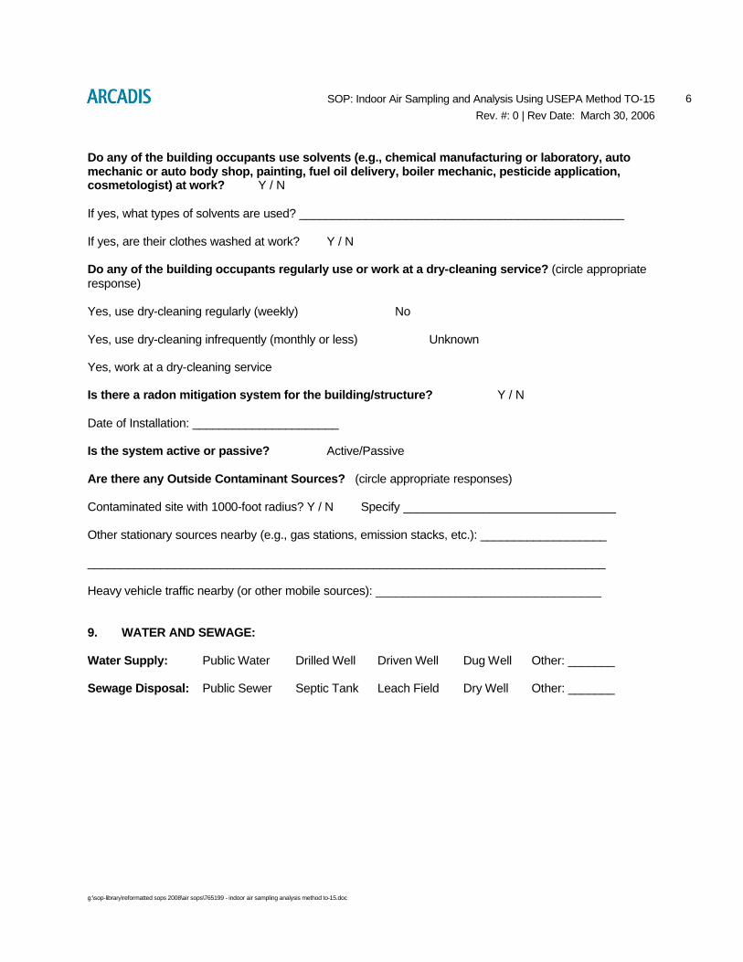
g:\sop-library\reformatted sops 2008\air sops\765199 - indoor air sampling analysis method to-15.doc
6SOP: Indoor Air Sampling and Analysis Using USEPA Method TO-15
Rev. #: 0 | Rev Date: March 30, 2006
Do any of the building occupants use solvents (e.g., chemical manufacturing or laboratory, auto mechanic or auto body shop, painting, fuel oil delivery, boiler mechanic, pesticide application, cosmetologist) at work? Y / N
If yes, what types of solvents are used? _________________________________________________
If yes, are their clothes washed at work? Y / N
Do any of the building occupants regularly use or work at a dry-cleaning service? (circle appropriate response)
Yes, use dry-cleaning regularly (weekly) No
Yes, use dry-cleaning infrequently (monthly or less) Unknown
Yes, work at a dry-cleaning service
Is there a radon mitigation system for the building/structure? Y / N
Date of Installation: ______________________
Is the system active or passive? Active/Passive
Are there any Outside Contaminant Sources? (circle appropriate responses)
Contaminated site with 1000-foot radius? Y / N Specify ________________________________
Other stationary sources nearby (e.g., gas stations, emission stacks, etc.): ___________________
______________________________________________________________________________
Heavy vehicle traffic nearby (or other mobile sources): __________________________________
9. WATER AND SEWAGE:
Water Supply: Public Water Drilled Well Driven Well Dug Well Other: _______
Sewage Disposal: Public Sewer Septic Tank Leach Field Dry Well Other: _______

g:\sop-library\reformatted sops 2008\air sops\765199 - indoor air sampling analysis method to-15.doc
7SOP: Indoor Air Sampling and Analysis Using USEPA Method TO-15
Rev. #: 0 | Rev Date: March 30, 2006
10. RELOCATION INFORMATION: (for oil spill residential emergency)
a. Provide reasons why relocation is recommended: __________________________________
__________________________________________________________________________________
b. Residents choose to: remain in home relocate to friends/family relocate to hotel/motel
c. Responsibility for costs associated with reimbursement explained? Y / N
d. Relocation package provided and explained to residents? Y / N
11. FLOOR PLANS:
Draw a plan view sketch of the basement and first floor of the building. Indicate air sampling locations, possible indoor air pollution sources and PID meter readings. If the building does not have a basement, please note.
Basement:

g:\sop-library\reformatted sops 2008\air sops\765199 - indoor air sampling analysis method to-15.doc
8SOP: Indoor Air Sampling and Analysis Using USEPA Method TO-15
Rev. #: 0 | Rev Date: March 30, 2006
First Floor:

g:\sop-library\reformatted sops 2008\air sops\765199 - indoor air sampling analysis method to-15.doc
9SOP: Indoor Air Sampling and Analysis Using USEPA Method TO-15
Rev. #: 0 | Rev Date: March 30, 2006
12. OUTDOOR PLOT:
Draw a sketch of the area surrounding the building being sampled. If applicable, provide information on spill locations, potential air contamination sources (industries, gas stations, repair shops, landfills, etc.), outdoor air sampling location(s), and PID meter readings.
Also indicate compass direction, wind direction and speed during sampling, the locations of the well and septic system, if applicable, and a qualifying statement to help locate the site on a topographic map.

g:\sop-library\reformatted sops 2008\air sops\765199 - indoor air sampling analysis method to-15.doc
10SOP: Indoor Air Sampling and Analysis Using USEPA Method TO-15
Rev. #: 0 | Rev Date: March 30, 2006
13. PRODUCT INVENTORY FORM:
Make and Model of field instrument used: _________________________________________________ List specific products found in the residence or area that have the potential to affect indoor air quality (e.g., gasoline or kerosene storage cans, glues, paints, cleaning solvents/products, polishes/waxes, new furniture/ carpet, nail polish/hairspray/cologne).
LocationProduct
DescriptionSize (units) Condition*
Chemical Ingredients
Field Instrument
Reading (units)
Photo** Y/N

g:\sop-library\reformatted sops 2008\air sops\765199 - indoor air sampling analysis method to-15.doc
11SOP: Indoor Air Sampling and Analysis Using USEPA Method TO-15
Rev. #: 0 | Rev Date: March 30, 2006
14. SAMPLING INFORMATION:
Sample Technician: ____________________________ Phone number: ( ) _______ - __________
Sample Source: Indoor Air / Sub-Slab / Near Slab Soil Gas / Exterior Soil Gas
Sampler Type: Tedlar Bag / Sorbent / Stainless Steel Canister / Other (specify): _________________
Analytical Method: TO-15 / TO-17 / Other: _________ Cert. Laboratory: _________________
Sample Locations (floor, room):
Field ID # _____ - ________________________ Field ID # _____ - __________________________
Field ID # _____ - ________________________ Field ID # _____ - __________________________
If distributed to occupants prior to sampling event, were the state-specific “Instructions for Occupants” followed? Yes / No
If not, describe modifications: __________________________________________________________
15. METEOROLOGICAL CONDITIONS:
Was there significant precipitation within 12 hours prior to (or during) the sampling event? Yes / No
Describe the general weather conditions: ____________________________________________________
_____________________________________________________________________________________
16. GENERAL OBSERVATIONS:
Provide any information that may be pertinent to the sampling event and may assist in the data interpretation process.
_____________________________________________________________________________________
_____________________________________________________________________________________
_____________________________________________________________________________________
_____________________________________________________________________________________

g:\sop-library\reformatted sops 2008\air sops\765199 - indoor air sampling analysis method to-15.doc
1SOP: Indoor Air Sampling and Analysis Using USEPA Method TO-15
Rev. #: 0 | Rev Date: March 30, 2006
ATTACHMENT B
Instrument Readings:
TimeCanister Pressure
(inches of HG)
Temperature(F or C)
Relative Humidity
(%)
Air Speed(ft/min)
Pressure Differential(inches of
H20)
PID(ppm or
ppb)
SUMMA Canister Information:
Size (circle one): 1 L 6 L
Canister ID:
Flow Controller ID:
General Observations/Notes:
Please record current weather information including wind speed and direction, ambient temperature, barometric pressure, and relative humidity via suitable information source (e.g., weatherunderground.com).
Indoor/Ambient Air Sample
Collection Log
Sample ID:
Client: Outdoor/Indoor:
Project: Sample Intake Height:
Location: Miscellaneous Equipment:
Project #: Time On/Off:
Samplers: Subcontractor:

Imagine the result
Ground Penetrating Radar
Rev. #: 02
Rev Date: May 2009

1SOP: Ground Penetrating Radar
Rev. #: 2 Rev Date: May 2009
Approval Signatures
Prepared by: Date: May 27, 2009
Reviewed by: Date: May 27, 2009
(Technical Expert)

2SOP: Ground Penetrating Radar
Rev. #: 2 Rev Date: May 2009
I. Scope and Application
This SOP document outlines the applications, limitations, and methodology for
acquiring and interpreting subsurface data using ground penetrating radar (GPR).
GPR is a non-invasive and non-destructive tool that detects electromagnetic
responses to high frequency radio waves transmitted by the GPR unit as it is pulled
along the surface. Subsurface objects or material contacts can be located based on
differences in their dielectric potential and/or electrical resistivity. The two most
important constraints of any GPR investigation are depth of penetration and required
resolution. These two constraints are inversely related to the signal frequency applied;
i.e., a higher frequency will yield better resolution, but less penetration and a lower
frequency will yield less resolution and deeper penetration.
II. Personnel Qualifications
GPR investigations should be conducted by qualified and experienced operators, such
as an experienced field technician and/or geophysicist. The GPR operator should be
experienced in evaluating data quality in the field and be able to adjust data acquisition
procedures in response to variable site conditions in order to identify anomalies and
resolve target features. Inexperienced ARCADIS personnel directing or supervising
GPR data acquisition, or interpreting processed GPR data should seek appropriate
guidance and technical peer review from qualified and experienced personnel.
III. Equipment List
The following equipment will be available, as required, during GPR surveys.
• Personal protective equipment (PPE), as required in the site Health and
Safety Plan (HASP);
• Appropriate forms, Site plans, field notebook, spray paint and camera;
• GSSI Model SIR-3000 radar instrument (or equivalent);
• a primary and, preferably, a secondary antennae of appropriate signal
frequency1
to match anticipated size and depth of targets;
• Non-conductive measuring tape or measuring wheel; and
1In general, the typical maximum depth of penetration varies from 9 feet with a 400
MHz antennae to 25 feet with a 200 MHz antennae.

3SOP: Ground Penetrating Radar
Rev. #: 2 Rev Date: May 2009
• Connecting cables and 12-volt power source.
IV. Cautions
The effectiveness of GPR is site-specific and subject to the skill level of the operator.
Reliability and efficiency is enhanced when used in conjunction with other geophysical
methods. Soils with higher electrical conductivity rapidly attenuate the radar energy,
reducing the penetration depth and resolution. Clayey soils and saturated soils,
particularly when high in soluble salts, limit the usefulness of GPR. Other potential
interference sources include subsurface debris, rebar reinforced concrete, above
ground reflective objects (cars, surface water, transmission lines), and electromagnetic
generating apparatus (electrical generators, radio transmitters).
Both metallic and nonmetallic utilities may be imaged by GPR. However, it should be noted that due to differences in the properties of materials, locating a plastic pipe may be more problematic than a metallic pipe because of a lesser dielectric contrast between plastic and soil. A guideline for effective locating depth for utilities is 1 inch (2.5 cm) diameter of utility can be discerned for each foot (0.3 m) of depth to a depth of 12 feet (3.7 m). For instance, one may expect to resolve a utility 10 inches (25 cm) in diameter at a depth of 10 feet (3 m). This is a general rule of thumb that can be applied to both metallic and non-metallic utilities, but should be used cautiously as the type of material can affect the resolution.
Also, the presence of reinforcing bar (rebar) in concrete can limit the resolution of pipes present below the concrete. The resolution of smaller diameter pipes present within or just below the concrete may be completed masked by the high response caused by the rebar.
V. Health and Safety Considerations
Minimize physical hazard exposure through use of proper PPE as prescribed in the
HASP. Maintain awareness of other potential hazards associated with the physical
location where the GPR investigation is being conducted and any ingress or egress
conditions.
VI. Procedure
1. Become familiar with the details of the applicability and limitations of GPR.
2. Evaluate site-specific soil information to determine suitability of soils (clay
content, saturation) for GPR. In general, soils with greater than 35% clay
content are considered restrictive, and soils with less than 10% clay content
are considered favorable for deep penetration with GPR.

4SOP: Ground Penetrating Radar
Rev. #: 2 Rev Date: May 2009
3. Evaluate meteorological information regarding recent or forecasted
precipitation that could impact soil moisture content and GPR effectiveness.
Schedule GPR surveys appropriately.
4. Perform site reconnaissance in advance to identify potential sources of
surface interference such as reinforced concrete, large metal objects, or
electrical generators).
5. Consider complimentary technologies to supplement GPR and provide
multiple lines of evidence. Technologies may include radio frequency,
magnetic, and/or electromagnetic surveys.
6. Employ only qualified and experienced GPR operators. For utility locating and
mapping applications, the GPR operator should be specifically experienced in
evaluating data quality and identifying anomalies in the field requiring
variations in data acquisition procedures to positively interpret and locate
targets of concern.
7. Consider the depth and size of subsurface features that GPR will be used for
identification. Attempt to match the signal frequency to the expected depth
and size of the subsurface feature. Change antennae as necessary for
variable depths and sizes of target objects. Consider the selection of a
primary and secondary choice of antennae, and use multiple antennae as
necessary. Evaluate GPR for known utility locations and/or relative to EM
results, as an indication of potential effectiveness. A guideline for effective
locating depths for utilities is 1-inch (2.5 cm) diameter of utility can be
discerned for each foot (0.3 m) of depth to a depth of 12 feet (3.7 m). Expect a
much coarser resolution below 12 feet.
8. Establish a reference grid over the area to be investigated and identify
traverse locations in the field notebook or on a site plan map.
9. Select and input a dielectric constant into the GPR unit based on knowledge
of the type of subsurface materials. Bear in mind that the dielectric constant is
an approximation based on assumed subsurface materials and may vary
based on the variability of the subsurface materials. The dielectric constant is
necessary to estimate the depth of a target, but should be considered an
approximation not an absolute. Multiple passes over a known utility may be
necessary using different dielectric constants before an accurate depth to a
target can be estimated.
10. The pace at which the GPR unit is moved along a traverse affects the target
resolution. It is recommended that an initial starting pace should be

5SOP: Ground Penetrating Radar
Rev. #: 2 Rev Date: May 2009
approximately 1.5 feet (0.5m) per second and modified if necessary during
field operations. Appropriate pacing can be determined in advance if the size
of the smallest target is known.
11. Record GPR data while slowly pulling the antenna along each survey
traverse. Annotate the record at even distance increments (10 feet, or as
needed) using the antenna’s marker switch.
12. Multiple traverses in opposite directions over the area being scanned are
recommended. A difference in data output for passes conducted in opposing
directions may warrant a third pass. This is not necessarily reflective of poor
data, but may indicate that anomalies observed are dipping at some angle
from horizontal with the ground surface.
13. The width of a single GPR profile scan is actually somewhat broader than that
of the antennae itself; however, it should be conservatively assumed that the
scan width corresponds to the width of the antennae.
VII. Waste Management
GPR is a non-invasive procedure and should not result in the generation of derived
wastes. Any trash or rubbish generated during the course of field activities should be
disposed of in a proper trash receptacle.
VIII. Data Recording and Management
Conduct data processing and analysis in accordance with the manufacturer’s
recommendations and industry practice. Processed data is available in electronic form
and as a paper printout. A copy of the field printout should be included in the project
files along with the field notebook. Electronic data (raw and processed) should be
maintained in accordance with data management procedures as outlined in the project
sampling analysis plan (SAP), quality assurance project plan (QAPP), data quality
objectives plan, or other applicable plan or guidance document.
IX. Quality Assurance
The following quality control procedures should be observed:
• Seek appropriate input prior to conducting a GPR survey to identify site-
specific features (soil conditions/sources of interference) that may impact data
acquisition.

6SOP: Ground Penetrating Radar
Rev. #: 2 Rev Date: May 2009
• Operate all equipment in accordance with manufacturer’s instructions and
recommended procedures. Record all system components (Unit, antennae
frequency, etc.) information in the field book.
• Data quality should be checked in the field to identify anomalies that may
require adjustment to the data acquisition procedures. Make appropriate
adjustments to data acquisition methods to achieve survey objectives, as
feasible.
• It is recommended that the operation and performance of the GPR equipment
is field checked (if possible) by locating existing underground utilities or
structures of known depth, size, and construction. These characteristics
should be similar to that of unidentified target objects.
• Data interpretation should undergo peer review by appropriate qualified and
experienced personnel.
X. References
US Army Corps of Engineers, 1995. Geophysical Exploration for Engineering and
Environmental Investigations, Engineering Manual (EM) 1110-1-1802.
Imagine the result
Chain-of-Custody, Handling, Packing and Shipping
Rev. #: 2
Rev Date: March 6, 2009
g:\sop-library\reformatted sops 2008\general sops\1663199 - chain-of-custody, handling, packing and shipping.doc
1SOP: Chain-of-Custody, Handling, Packing and Shipping
Rev. #: 2 | Rev Date: March 6, 2009
Approval Signatures
Prepared by: Date: 3/6/09
Caron Koll
Reviewed by: Date: 3/6/09
Jane Kennedy(Technical Expert)

g:\sop-library\reformatted sops 2008\general sops\1663199 - chain-of-custody, handling, packing and shipping.doc
2SOP: Chain-of-Custody, Handling, Packing and Shipping
Rev. #: 2 | Rev Date: March 6, 2009
I. Scope and Application
This Standard Operating Procedure (SOP) describes the chain-of-custody, handling,
packing, and shipping procedures for the management of samples to decrease the
potential for cross-contamination, tampering, mis-identification, and breakage, and to
insure that samples are maintained in a controlled environment from the time of
collection until receipt by the analytical laboratory.
II. Personnel Qualifications
ARCADIS field sampling personnel will have current health and safety training,
including 40-hour HAZWOPER training, Department of Transportation (DOT) training,
site supervisor training, and site-specific training, as needed. In addition, ARCADIS
field sampling personnel will be versed in the relevant SOPs and possess the skills
and experience necessary to successfully complete the desired field work.
III. Equipment List
The following list provides materials that may be required for each project. Project
documents and sample collection requirements should be reviewed prior to initiating
field operations:
• indelible ink pens (black or blue);
• polyethylene bags (resealable-type);
• clear packing tape, strapping tape, duct tape;
• chain of custody
• DOT shipping forms, as applicable
• custody seals or tape;
• appropriate sample containers and labels,;
• insulated coolers of adequate size for samples and sufficient ice to maintain
4°C during collection and transfer of samples;
• wet ice;
• cushioning and absorbent material (i.e., bubble wrap or bags);

g:\sop-library\reformatted sops 2008\general sops\1663199 - chain-of-custody, handling, packing and shipping.doc
3SOP: Chain-of-Custody, Handling, Packing and Shipping
Rev. #: 2 | Rev Date: March 6, 2009
• temperature blank
• sample return shipping papers and addresses; and
• field notebook.
IV. Cautions
Review project requirements and select appropriate supplies prior to field mobilization.
Insure that appropriate sample containers with applicable preservatives, coolers, and
packing material have been supplied by the laboratory.
Understand the offsite transfer requirements for the facility at which samples are
collected.
If overnight courier service is required schedule pick-up or know where the drop-off
service center is located and the hours of operation. Prior to using air transportation,
confirm air shipment is acceptable under DOT and International Air Transport
Association (IATA) regulation
Schedule pick-up time for laboratory courier or know location of laboratory/service
center and hours of operation.
Understand DOT and IATA shipping requirements and evaluate dangerous goods
shipping regulations relative to the samples being collected (i.e. complete an
ARCADIS shipping determination). Review the ARCADIS SOPs for shipping,
packaging and labeling of dangerous goods. Potential samples requiring compliance
with this DOT regulation include:
• Methanol preservation for Volatile Organic Compounds in soil samples
• Non-aqueous phase liquids (NAPL)
V. Health and Safety Considerations
Follow health and safety procedures outlined in the project/site Health and Safety Plan
(HASP).

g:\sop-library\reformatted sops 2008\general sops\1663199 - chain-of-custody, handling, packing and shipping.doc
4SOP: Chain-of-Custody, Handling, Packing and Shipping
Rev. #: 2 | Rev Date: March 6, 2009
Use caution and appropriate cut resistant gloves when tightening lids to 40 mL vials.
These vials can break while tightening and can lacerate hand. Amber vials (thinner
glass) are more prone to breakage.
Some sample containers contain preservatives.
• The preservatives must be retained in the sample container and should in no
instance be rinsed out.
• Preservatives may be corrosive and standard care should be exercised to
reduce potential contact to personnel skin or clothing. Follow project safety
procedures if spillage is observed.
• If sample container caps are broken discard the bottle. Do not use for sample
collection.
VI. Procedure
Chain-of-Custody Procedures
1. Prior to collecting samples, complete the chain-of-custody record header
information by filling in the project number, project name, and the name(s) of the
sampling technician(s) and other relevant project information. Attachment 1
provides an example chain-o- custody record
2. Chain-of-custody information MUST be printed legibly using indelible ink (black
or blue).
3. After sample collection, enter the individual sample information on the chain-of-
custody:
a. Sample Identification indicates the well number or soil location that the
sample was collected from. Appropriate values for this field include well
locations, grid points, or soil boring identification numbers (e.g., MW-3, X-
20, SB-30). When the depth interval is included, the complete sample ID
would be “SB-30 (0.5-1.0) where the depth interval is in feet. Please
note it is very important that the use of hyphens in sample names and
depth units (i.e., feet or inches) remain consistent for all samples entered
on the chain-of-custody form. DO NOT use the apostrophe or quotes in
the sample ID. Sample names may also use the abbreviations “FB,”
“TB,” and “DUP” as prefixes or suffixes to indicate that the sample is a
field blank, trip blank, or field duplicate, respectively. NOTE: The sample

g:\sop-library\reformatted sops 2008\general sops\1663199 - chain-of-custody, handling, packing and shipping.doc
5SOP: Chain-of-Custody, Handling, Packing and Shipping
Rev. #: 2 | Rev Date: March 6, 2009
nomenclature may be dictated by the project database and require
unique identification for each sample collected for the project. Consult
the project data management plan for additional information regarding
sample identification.
b. List the date o sample collection. The date format to be followed should
be mm/dd/yy (e.g., 03/07/09) or mm/dd/yyyy (e.g. 03/07/2009).
c. List the time that the sample was collected. The time value should be
presented using military format. For example, 3:15 P.M. should be
entered as 15:15.
d. The composite field should be checked if the sample is a composite over
a period of time or from several different locations and mixed prior to
placing in sample containers.
e. The “Grab”. field should be marked with an “X” if the sample was
collected as an individual grab sample. (e.g. monitoring well sample or
soil interval).
f. Any sample preservation should be noted.
g. The analytical parameters that the samples are being analyzed for should
be written legibly on the diagonal lines. As much detail as possible should
be presented to allow the analytical laboratory to properly analyze the
samples. For example, polychlorinated biphenyl (PCB) analyses may be
represented by entering “PCBs” or “Method 8082.” Multiple methods
and/or analytical parameters may be combined for each column (e.g.,
PCBs/VOCs/SVOCs or 8082/8260/8270). These columns should also be
used to present project-specific parameter lists (e.g., Appendix IX+3
target analyte list. Each sample that requires a particular parameter
analysis will be identified by placing the number of containers in the
appropriate analytical parameter column. For metals in particular, indicate
which metals are required.
h. Number of containers for each method requested. This information may
be included under the parameter or as a total for the sample based on
the chain of custody form used.
i. Note which samples should be used for site specific matrix spikes.
j. Indicate any special project requirements.

g:\sop-library\reformatted sops 2008\general sops\1663199 - chain-of-custody, handling, packing and shipping.doc
6SOP: Chain-of-Custody, Handling, Packing and Shipping
Rev. #: 2 | Rev Date: March 6, 2009
k. Indicate turnaround time required.
l. Provide contact name and phone number in the event that problems are
encountered when samples are received at the laboratory.
m. If available attach the Laboratory Task Order or Work Authorization forms
n. The remarks field should be used to communicate special analytical
requirements to the laboratory. These requirements may be on a per
sample basis such as “extract and hold sample until notified,” or may be
used to inform the laboratory of special reporting requirements for the
entire sample delivery group (SDG). Reporting requirements that should
be specified in the remarks column include: 1) turnaround time; 2) contact
and address where data reports should be sent; 3) name of laboratory
project manager; and 4) type of sample preservation used.
o. The “Relinquished By” field should contain the signature of the sampling
technician who relinquished custody of the samples to the shipping
courier or the analytical laboratory.
p. The “Date” field following the signature block indicates the date the
samples were relinquished. The date format should be mm/dd/yyyy (e.g.,
03/07/2005).
q. The “Time” field following the signature block indicates the time that the
samples were relinquished. The time value should be presented using
military format. For example, 3:15 P.M. should be entered as 15:15.
r. The “Received By” section is signed by sample courier or laboratory
representative who received the samples from the sampling technician or
it is signed upon laboratory receipt from the overnight courier service.
3. Complete as many chain-of-custody forms as necessary to properly document
the collection and transfer of the samples to the analytical laboratory.
4. Upon completing the chain-of-custody forms, forward two copies to the
analytical laboratory and retain one copy for the field records.
5. If electronic chain-of-custody forms are utilized, sign the form and make 1 copy
for ARCADIS internal records and forward the original with the samples to the
laboratory.

g:\sop-library\reformatted sops 2008\general sops\1663199 - chain-of-custody, handling, packing and shipping.doc
7SOP: Chain-of-Custody, Handling, Packing and Shipping
Rev. #: 2 | Rev Date: March 6, 2009
Handling Procedures
1. After completing the sample collection procedures, record the following
information in the field notebook with indelible ink:
• project number and site name;
• sample identification code and other sample identification information, if
appropriate;
• sampling method;
• date;
• name of sampler(s);
• time;
• location (project reference);
• location of field duplicates and both sample identifications;
• locations that field QC samples were collected including equipment blanks,
field blanks and additional sample volume for matrix spikes; and
• any comments.
2. Complete the sample label with the following information in indelible ink:
• sample type (e.g., surface water);
• sample identification code and other sample identification information, if
applicable;
• analysis required;
• date;
• time sampled; and
• initials of sampling personnel;

g:\sop-library\reformatted sops 2008\general sops\1663199 - chain-of-custody, handling, packing and shipping.doc
8SOP: Chain-of-Custody, Handling, Packing and Shipping
Rev. #: 2 | Rev Date: March 6, 2009
• sample matrix; and
• preservative added, if applicable.
3. Cover the label with clear packing tape to secure the label onto the container
and to protect the label from liquid.
4. Confirm that all caps on the sample containers are secure and tightly closed.
5. In some instances it may be necessary to wrap the sample container cap with
clear packing tape to prevent it from becoming loose.
6. For some projects individual custody seals may be required. Custody seal
evidence tape may be placed on the shipping container or they may be placed
on each sample container such that the cooler or cap cannot be opened without
breaking the custody seal. The custody seal should be initialed and dated prior
to relinquishing the samples.
Packing Procedures
Following collection, samples must be placed on wet ice to initiate cooling to 4°C
immediately. Retain samples on ice until ready to pack for shipment to the laboratory.
1. Secure the outside and inside of the drain plug at the bottom of the cooler being
used for sample transport with “Duct” tape.
2. Place a new large heavy duty plastic garbage bag inside each cooler
3. Place each sample bottle wrapped in bubble wrap inside the garbage bag.
VOC vials may be grouped by sample in individual resealable plastic bags). If a
cooler temperature blank is supplied by the laboratory, it should be packaged
following the same procedures as the samples. If the laboratory did not include
a temperature blank, do not add one. Place 1 to 2 inches of cushioning material
(i.e., vermiculite) at the bottom of the cooler.
4. Place the sealed sample containers upright in the cooler.
5. Package ice in large resealable plastic bags and place inside the large garbage
bag in the cooler. Samples placed on ice will be cooled to and maintained at a
temperature of approximately 4°C.

g:\sop-library\reformatted sops 2008\general sops\1663199 - chain-of-custody, handling, packing and shipping.doc
9SOP: Chain-of-Custody, Handling, Packing and Shipping
Rev. #: 2 | Rev Date: March 6, 2009
6. Fill the remaining space in the cooler with cushioning material such as bubble
wrap. The cooler must be securely packed and cushioned in an upright position
and be surrounded (Note: to comply with 49 CFR 173.4, filled cooler must not
exceed 64 pounds).
7. Place the completed chain-of-custody record(s) in a large resealable bag and
tape the bag to the inside of the cooler lid.
8. Close the lid of the cooler and fasten with packing tape.
9. Wrap strapping tape around both ends of the cooler.
10. Mark the cooler on the outside with the following information: shipping address,
return address, “Fragile, Handle with Care” labels on the top and on one side,
and arrows indicating “This Side Up” on two adjacent sides.
11. Place custody seal evidence tape over front right and back left of the cooler lid,
initial and date, then cover with clear plastic tape.
Note: Procedure numbers 2, 3, 5, and 6 may be modified in cases where laboratories
provide customized shipping coolers. These cooler types are designed so the sample
bottles and ice packs fit snugly within preformed styrofoam cushioning and insulating
packing material.
Shipping Procedures
1. All samples will be delivered by an express carrier within 48 hours of sample
collection. Alternatively, samples may be delivered directly to the laboratory or
laboratory service center or a laboratory courier may be used for sample pickup.
2. If parameters with short holding times are required (e.g., VOCs [EnCore™
Sampler], nitrate, nitrite, ortho-phosphate and BOD), sampling personnel will
take precautions to ship or deliver samples to the laboratory so that the holding
times will not be exceeded.
3. Samples must be maintained at 4°C+2°C until shipment and through receipt at
the laboratory
4. All shipments must be in accordance with DOT regulations and ARCADIS
dangerous goods shipping SOPs.

g:\sop-library\reformatted sops 2008\general sops\1663199 - chain-of-custody, handling, packing and shipping.doc
10SOP: Chain-of-Custody, Handling, Packing and Shipping
Rev. #: 2 | Rev Date: March 6, 2009
5. When the samples are received by the laboratory, laboratory personnel will
complete the chain-of-custody by recording the date and time of receipt of
samples, measuring and recording the internal temperature of the shipping
container, and checking the sample identification numbers on the containers to
ensure they correspond with the chain-of-custody forms.
Any deviations between the chain-of-custody and the sample containers, broken
containers, or temperature excursions will be communicated to ARCADIS immediately
by the laboratory.
VII. Waste Management
Not applicable
VIII. Data Recording and Management
Chain-of-custody records will be transmitted to the ARCADIS PM or designee at the
end of each day unless otherwise directed by the ARCADIS PM. The sampling team
leader retains copies of the chain-of-custody forms for filing in . the project file. Record
retention shall be in accordance with project requirements.
IX. Quality Assurance
Chain-of-custody forms will be legibly completed in accordance with the applicable
project documents such as Sampling and Analysis Plan (SAP), Quality Assurance
Project Plan (QAPP), Work Plan, or other project guidance documents. A copy of the
completed chain-of-custody form will be sent to the ARCADIS Project Manager or
designee for review.
X. References
Not Applicable

g:\sop-library\reformatted sops 2008\general sops\1663199 - chain-of-custody, handling, packing and shipping.doc
1SOP: Chain-of-Custody, Handling, Packing and Shipping
Rev. #: 2 | Rev Date: March 6, 2009
Attachment 1

Imagine the result
Monitoring Well Development
Rev. #: 2
Rev Date: March 18, 2009
g:\sop-library\reformatted sops 2008\hydrogeology sops\1713199 - monitoring well development.doc
1SOP: Monitoring Well Development
Rev. #: 2 | Rev Date: March 18, 2009
Approval Signatures
Prepared by: Date: 3/18/09
David Lipson
Reviewed by: Date: 3/18/09
Michael Gefell (Technical Expert)

g:\sop-library\reformatted sops 2008\hydrogeology sops\1713199 - monitoring well development.doc
2SOP: Monitoring Well Development
Rev. #: 2 | Rev Date: March 18, 2009
I. Scope and Application
Monitoring wells (or piezometers, well points, or micro-wells) will be developed to clear
them of fine-grained sediment and any drilling fluids that may have been used during
well installation, and enhance the hydraulic connection between the well and the
surrounding geologic formation. Development will be accomplished by evacuating well
water by either pumping or bailing. Prior to pumping or bailing, the screened interval
can be gently surged using a surge block, bailer, or inertia pump with optional surge-
block fitting. In addition, sediment accumulated in the bottom of the well can be
removed by bailing with a bottom-loading bailer or pumping using a submersible or
inertia pump with optional surge-block fitting.
Pumping methods will be selected based on site-specific geologic conditions,
anticipated well yield, water table depth, and groundwater monitoring objectives, and
may include one or more of the following.
• submersible pump
• inertial pump (Waterra™ pump or equivalent)
• bladder pump
• peristaltic pump
• centrifugal pump
When developing a well using the pumping method, the pump (or, with inertial pumps,
the tubing) is lowered to the screened portion of the well. During purging, the pump or
tubing is moved up and down the screened interval until the well yields relatively clear
water.
Submersible pumps have a motor-driven impeller that pushes the groundwater
through discharge tubing to the ground surface. Inertial pumps have a check valve at
the bottom of stiff tubing which, when operated up and down, lifts water to the ground
surface. Bladder pumps have a bottom check valve and a flexible internal bladder that
fills from below and is then compressed using pressurized air to force water out the top
of the bladder through the discharge tubing to the ground surface. These three types
of pumps have a wide range of applicability in terms of well depth and water depth.
Centrifugal and peristaltic pumps use atmospheric pressure to lift water from the well,
and therefore can only be practically used where the depth to water is less than 25
feet.

g:\sop-library\reformatted sops 2008\hydrogeology sops\1713199 - monitoring well development.doc
3SOP: Monitoring Well Development
Rev. #: 2 | Rev Date: March 18, 2009
II. Personnel Qualifications
Monitoring well development activities will be performed by persons who have been
trained in proper well development procedures under the guidance of an experienced
field geologist, engineer, or technician.
III. Equipment List
Materials for monitoring well development using a pump include the following
• health and safety equipment, as required by the site Health and Safety Plan
(HASP)
• cleaning equipment
• photoionization detector (PID) to measure headspace vapors
• pump
• polyethylene pump discharge tubing
• plastic sheeting
• power source (generator or battery)
• field notebook and/or personal digital assistant (PDA)
• graduated pails
• appropriate containers
• monitoring well keys
• water level indicator
Materials for monitoring well development using a bailer include the following.
• personal protective equipment (PPE) as required by the HASP
• cleaning equipment
• PID to measure headspace vapors

g:\sop-library\reformatted sops 2008\hydrogeology sops\1713199 - monitoring well development.doc
4SOP: Monitoring Well Development
Rev. #: 2 | Rev Date: March 18, 2009
• bottom-loading bailer, sand bailer
• polypropylene or nylon rope
• plastic sheeting
• graduated pails
• appropriate containers
• keys to wells
• field notebook and/or PDA
• water level indicator
IV. Cautions
Where surging is performed to assist in removing fine-grained material from the sand
pack, surging must be performed in a gentle manner. Excessive suction could
promote fine-grained sediment entry into the outside of the sand pack from the
formation.
Avoid using development fluids or materials that could impact groundwater or soil
quality, or could be incompatible with the subsurface conditions.
In some cases it may be necessary to add potable water to a well to allow surging and
development, especially for new monitoring wells installed in low permeability
formations. Before adding potable water to a well, the Project Manager (PM) must be
notified and the PM shall make the decision regarding the appropriateness and
applicability of adding potable water to a well during well development procedures. If
potable water is to be added to a well as part of development, the potable water
source should be sampled and analyzed for constituents of concern, and the results
evaluated by the PM prior to adding the potable water to the well. If potable water is
added to a well for development purposes, at the end of development the well will be
purged dry to remove the potable water, or if the well no longer goes dry then the well
will be purged to remove at least three times the volume of potable water that was
added.

g:\sop-library\reformatted sops 2008\hydrogeology sops\1713199 - monitoring well development.doc
5SOP: Monitoring Well Development
Rev. #: 2 | Rev Date: March 18, 2009
V. Health and Safety Considerations
Field activities associated with monitoring well development will be performed in
accordance with a site-specific HASP, a copy of which will be present on site during
such activities.
VI. Procedure
1. The procedures for monitoring well development are described below. (Note:
Steps 7, 8, and 10 can be performed contemporaneously using an inertial pump
with a surge-block fitting.)
2. Don appropriate PPE (as required by the HASP).
3. Place plastic sheeting around the well.
4. Clean all equipment entering each monitoring well, except for new, disposable
materials that have not been previously used.
5. Open the well cover while standing upwind of the well, remove well cap. Insert
PID probe approximately 4 to 6 inches into the casing or the well headspace
and cover with gloved hand. Record the PID reading in the field notebook. If
the well headspace reading is less than 5 PID units, proceed; if the headspace
reading is greater than 5 PID units, screen the air within the breathing zone. If
the PID reading in the breathing zone is below 5 PID units, proceed. If the PID
reading is above 5 PID units, move upwind from well for 5 minutes to allow the
volatiles to dissipate. Repeat the breathing zone test. If the reading is still
above 5 PID units, don the appropriate respiratory protection in accordance with
the requirements of the HASP. Record all PID readings.
6. Obtain an initial measurement of the depth to water and the total well depth from
the reference point at the top of the well casing. Record these measurements in
the field log book.
7. Lower a surge block or bailer into the screened portion of the well. Gently raise
and lower the surge block or bailer within the screened interval of the well to
force water in and out of the screen slots and sand pack. Continue surging for
15 to 30 minutes. Note that this step is optional but recommended for all new
wells/piezometers, particularly in formations with a relatively high content of fine-
grained material.

g:\sop-library\reformatted sops 2008\hydrogeology sops\1713199 - monitoring well development.doc
6SOP: Monitoring Well Development
Rev. #: 2 | Rev Date: March 18, 2009
8. Lower a bottom-loading bailer to the bottom of the well and gently bounce the
bailer on the bottom of the well to collect accumulated sediment, if any.
Remove and empty the bailer. Repeat until the bailed water is free of excessive
sediment and the bottom of the well feels solid. Alternatively, measurement of
the well depth with a water level indicator can be used to verify that sediment
and/or silt has been removed to the extent practicable, based on a comparison
with the well installation log or previous measurement of total well depth.
9. After surging the well and removing excess accumulated sediment from the
bottom of the well, re-measure the depth-to-water and the total well depth from
the reference point at the top of the well casing. Record these measurements in
the field log book.
10. Remove formation water by pumping or bailing. Where pumping is used,
measure and record the pre-pumping water level. Operate the pump at a
relatively constant rate. Measure the pumping rate using a calibrated container
and stop watch, and record the pumping rate in the field log book. Measure and
record the water level in the well at least once every 5 minutes during pumping.
Note any relevant observations in terms of water color, visual level of turbidity,
sheen, odors, etc. Pump or bail for 30 to 60 minutes or until termination criteria
specified in the Work Plan or Field Sampling Plan (FSP) are reached. Record
the total volume of water purged from the well.
11. If the well goes dry, stop pumping or bailing and allow well to recover. Resume
pumping or bailing when sufficient water has recharged the well.
12. Contain all water in appropriate containers.
13. When complete, secure the lid back on the well.
14. Place disposable materials in plastic bags for appropriate disposal and
decontaminate reusable, downhole pump components and/or bailer.
VII. Waste Management
Materials generated during monitoring well installation and development will be placed
in appropriate labeled containers and disposed of as described in the Work Plan or
Field Sampling Plan.

g:\sop-library\reformatted sops 2008\hydrogeology sops\1713199 - monitoring well development.doc
7SOP: Monitoring Well Development
Rev. #: 2 | Rev Date: March 18, 2009
VIII. Data Recording and Management
Well development activities will be documented in a proper field notebook and/or PDA.
Pertinent information will include personnel present on site; times of arrival and
departure; significant weather conditions; timing of well development activities;
development method(s); observations of purge water color, turbidity, odor, sheen, etc.;
purge rate; and water levels before and during pumping.
IX. Quality Assurance
All reused, non-disposable, downhole well development equipment will be cleaned in
accordance with the procedures outlined in the Field Equipment Cleaning-
Decontamination SOP.
X. References
Not Applicable.

Imagine the result
Monitoring Well Installation
Rev. #: 2
Rev Date: August 22, 2008

g:\sop-library\reformatted sops 2008\hydrogeology sops\1723199 - monitoring well installation.doc
1SOP: Monitoring Well Installation
Rev. #: 2 | Rev Date: March 24, 2008
Approval Signatures
Prepared by: Date: 8/25/08
Reviewed by: Date: 8/25/08
(Technical Expert)

g:\sop-library\reformatted sops 2008\hydrogeology sops\1723199 - monitoring well installation.doc
2SOP: Monitoring Well Installation
Rev. #: 2 | Rev Date: March 24, 2008
I. Scope and Application
The procedures set out herein are designed to produce standard groundwater
monitoring wells suitable for: (1) groundwater sampling, (2) water level measurement,
(3) bulk hydraulic conductivity testing of formations adjacent to the open interval of the
well.
Monitoring well boreholes in unconsolidated (overburden) materials are typically drilled
using the hollow-stem auger drilling method. Other drilling methods that are also
suitable for installing overburden monitoring wells, and are sometimes necessary due
to site-specific geologic conditions, include: drive-and-wash, spun casing, Rotasonic,
dual-rotary (Barber Rig), and fluid/mud rotary with core barrel or roller bit. Direct-push
techniques (e.g., Geoprobe or cone penetrometer) and driven well points may also be
used in some cases within the overburden. Monitoring wells within consolidated
materials such as bedrock are commonly drilled using water-rotary (coring or tri-cone
roller bit), air rotary or Rotasonic methods. The drilling method to be used at a given
site will be selected based on site-specific consideration of anticipated drilling/well
depths, site or regional geologic knowledge, type of monitoring to be conducted using
the installed well, and cost.
No oils or grease will be used on equipment introduced into the boring (e.g., drill rod,
casing, or sampling tools). No coated bentonite pellets will be used in the well drilling
or construction process. Specifications of materials to be installed in the well will be
obtained prior to mobilizing onsite, including:
• well casing;
• bentonite;
• sand; and
• grout.
Well materials will be inspected and, if needed, cleaned prior to installation.
II. Personnel Qualifications
Monitoring well installation activities will be performed by persons who have been
trained in proper well installation procedures under the guidance of an experienced
field geologist, engineer, or technician. Where field sampling is performed for soil or
bedrock characterization, field personnel will have undergone in-field training in soil or

g:\sop-library\reformatted sops 2008\hydrogeology sops\1723199 - monitoring well installation.doc
3SOP: Monitoring Well Installation
Rev. #: 2 | Rev Date: March 24, 2008
bedrock description methods, as described in the appropriate SOP(s) for those
activities.
III. Equipment List
The following materials will be available during soil boring and monitoring well
installation activities, as required:
• Site Plan with proposed soil boring/well locations;
• Work Plan or Field Sampling Plan (FSP), and site Health and Safety Plan
(HASP);
• personal protective equipment (PPE), as required by the HASP;
• traffic cones, delineators, caution tape, and/or fencing as appropriate for
securing the work area, if such are not provided by drillers;
• appropriate soil sampling equipment (e.g., stainless steel spatulas, knife);
• soil and/or bedrock logging equipment as specified in the appropriate SOPs;
• appropriate sample containers and labels;
• drum labels as required for investigation derived waste handling;
• chain-of-custody forms;
• insulated coolers with ice, when collecting samples requiring preservation by
chilling;
• photoionization detector (PID) or flame ionization detector (FID);
• ziplock style bags;
• water level or oil/water interface meter;
• locks and keys for securing the well after installation;
• decontamination equipment (bucket, distilled or deionized water, cleansers
appropriate for removing expected chemicals of concern, paper towels);

g:\sop-library\reformatted sops 2008\hydrogeology sops\1723199 - monitoring well installation.doc
4SOP: Monitoring Well Installation
Rev. #: 2 | Rev Date: March 24, 2008
• field notebook.
Prior to mobilizing to the site, ARCADIS personnel will contact the drilling
subcontractor or in-house driller (as appropriate) to confirm that appropriate sampling
and well installation equipment will be provided. Specifications of the sampling and
well installation equipment are expected to vary by project, and so communication with
the driller will be necessary to ensure that the materials provided will meet the project
objectives. Equipment typically provided by the driller could include:
• drilling equipment required by the American Society of Testing and Materials
(ASTM) D 1586, when performing split-spoon sampling;
• disposable plastic liners, when drilling with direct-push equipment;
• drums for investigation derived waste;
• drilling and sampling equipment decontamination materials;
• decontamination pad materials, if required; and
• well construction materials.
IV. Cautions
Prior to beginning field work, underground utilities in the vicinity of the drilling areas will
be delineated by the drilling contractor or an independent underground utility locator
service. See separate SOP for utility clearance.
Some regulatory agencies require a minimum annular space between the well or
permanent casing and the borehole wall. When specified, the minimum clearance is
typically 2 inches on all sides (e.g., a 2-inch diameter well requires a 6-inch diameter
borehole). In addition, some regulatory agencies have specific requirements regarding
grout mixtures. Determine whether the oversight agency has any such requirements
prior to finalizing the drilling and well installation plan.
If dense non-aqueous phase liquids (DNAPL) are known or expected to exist at the
site, refer to the DNAPL Contingency Plan SOP for additional details regarding drilling
and well installation to reduce the potential for inadvertent DNAPL remobilization.
Avoid using drilling fluids or materials that could impact groundwater or soil quality, or
could be incompatible with the subsurface conditions.

g:\sop-library\reformatted sops 2008\hydrogeology sops\1723199 - monitoring well installation.doc
5SOP: Monitoring Well Installation
Rev. #: 2 | Rev Date: March 24, 2008
Similarly, consider the material compatibility between the well materials and the
surrounding environment. For example, PVC well materials are not preferred when
DNAPL is present. In addition, some groundwater conditions leach metals from
stainless steel.
Water used for drilling and sampling of soil or bedrock, decontamination of
drilling/sampling equipment, or grouting boreholes upon completion will be of a quality
acceptable for project objectives. Testing of water supply should be considered.
Specifications of materials used for backfilling bore hole will be obtained, reviewed and
approved to meet project quality objectives. Bentonite is not recommended where
DNAPLs are likely to be present. In these situations, neat cement grout is preferred.
No coated bentonite pellets will be used in monitoring well construction, as the coating
could impact the water quality in the completed well.
Monitoring wells may be installed with Schedule 40 polyvinyl chloride (PVC) to a
maximum depth of 200 feet below ground surface (bgs). PVC monitoring wells
between 200 and 400 feet total depth will be constructed using Schedule 80 PVC.
Monitoring wells deeper than 400 feet will be constructed using steel.
V. Health and Safety Considerations
Field activities associated with monitoring well installation will be performed in
accordance with a site-specific HASP, a copy of which will be present on site during
such activities.
VI. Procedures
The procedures for installing groundwater monitoring wells are presented below:
Hollow-Stem Auger, Drive-and-Wash, Spun Casing, Fluid/Mud Rotary, Rotasonic, and
Dual-Rotary Drilling Methods
1. Locate boring/well location, establish work zone, and set up sampling
equipment decontamination area.
2. Advance boring to desired depth. Collect soil and/or bedrock samples at
appropriate interval as specified in the Work Plan and/or FSP. Collect,
document, and store samples for laboratory analysis as specified in the Work
Plan and/or FSP. Decontaminate equipment between samples in accordance
with the Work Plan and/or FSP. A common sampling method that produces

g:\sop-library\reformatted sops 2008\hydrogeology sops\1723199 - monitoring well installation.doc
6SOP: Monitoring Well Installation
Rev. #: 2 | Rev Date: March 24, 2008
high-quality soil samples with relatively little soil disturbance is the ASTM D
1586 - Standard Test Method for Penetration Test and Split-Barrel Sampling of
Soils. Split-spoon samples are obtained during drilling using hollow-stem auger,
drive-and-wash, spun casing, and fluid/mud rotary. Rotasonic drilling produces
large-diameter soil cores that tend to be more disturbed than split-spoon
samples due to the vibratory action of the drill casing. Dual-rotary removes
cuttings by compressed air and allows only a general assessment of geology.
High-quality bedrock samples can be obtained by coring.
3. Describe each soil or bedrock sample as outlined in the appropriate SOP.
Record descriptions in the field notebook and/or personal digital assistant
(PDA). It should be noted that PDA logs must be electronically backed up and
transferred to a location accessible to other project team members as soon as
feasible to retain and protect the field data. During soil boring advancement,
document all drilling events in field notebook, including blow counts (number of
blows required to advance split-spoon sampler in 6-inch increments) and work
stoppages. Blow counts will not be available if Rotasonic, dual-rotary, or direct-
push methods are used. When drilling in bedrock, the rate of penetration
(minutes per foot) is recorded.
4. If it is necessary to install a monitor well into a permeable zone below a
confining layer, particularly if the deeper zone is believed to have water quality
that differs significantly from the zone above the confining layer, then a
telescopic well construction should be considered. In this case, the borehole is
advanced approximately 3 to 5 feet into the top of the confining layer, and a
permanent casing (typically PVC, black steel or stainless steel) is installed into
the socket drilled into the top of the confining layer. The casing is then grouted
in place. The preferred methods of grouting telescoping casings include:
pressure-injection grouting using an inflatable packer installed temporarily into
the base of the casing, such that grout is injected out the bottom of the casing
until it is observed at ground surface outside the casing; displacement-method
grouting (also known as the Halliburton method), which entails filling the casing
with grout and displacing the grout out the bottom of the casing by pushing a
drillable plug, typically made of wood to the bottom of the casing, following by
tremie grouting the remainder of the annulus outside the casing; or tremie
grouting the annulus surrounding the casing using a tremie pipe installed to the
base of the borehole. In all three cases, the casing is grouted to the ground
surface, and the grout is allowed to set prior to drilling deeper through the
casing. Site-specific criteria and work plans should be created for the
completion of non-standard monitoring wells, including telescopic wells.

g:\sop-library\reformatted sops 2008\hydrogeology sops\1723199 - monitoring well installation.doc
7SOP: Monitoring Well Installation
Rev. #: 2 | Rev Date: March 24, 2008
5. In consolidated formations such as competent bedrock, a monitoring well may
be completed with an open borehole interval without a screen and sandpack. In
these cases, the borehole is advanced to the targeted depth of the top of the
open interval. A permanent casing is then grouted in place following the
procedures described in Step 4 above. After the grout sets, the borehole is
advanced by drilling through the permanent casing to the targeted bottom depth
of the open interval, which then serves as the monitoring interval for the well. If
open-borehole interval stability is found to be questionable or if a specific depth
interval is later selected for monitoring, a screened monitoring well may later be
installed within the open-borehole interval, depending on the annular space and
well diameter requirements.
6. Prior to screened well installation or after the completion of an open-bedrock
well, the water level or oil/water interface probe should be used to determine the
static water level in the borehole in relation to the proposed well screen or open-
interval location. If necessary, an open-bedrock well may be drilled deeper to
intersect the water table or a permeable water-bearing zone.
7. Upon completing the borehole to the desired depth, if a screened well
construction is desired, install the monitoring well by lowering the screen and
casing assembly with sump through the augers or casing. Monitoring wells
typically will be constructed of 2-inch-diameter, flush-threaded PVC or stainless
steel slotted well screen and blank riser casing. Smaller diameters may be used
if wells are installed using direct-push methodology or if multiple wells are to be
installed in a single borehole. The screen length will be specified in the Work
Plan or FSP based on regulatory requirements and specific monitoring
objectives. Monitoring well screens are usually 5 to 10 feet long, but may be up
to 25 feet long in very low permeability, thick geologic formations. The screen
length will depend on the purpose for the well and the objectives of the
groundwater investigation. Typically, the slot size will be 0.010 inch and the
sand pack will be 20-40, Morie No. 0, or equivalent. In very fine-grained
formations where sample turbidity needs to be minimized, it may be preferred to
use a 0.006-inch slot size and 30-65, Morie No. 00, or equivalent sand pack.
Alternatively, where monitoring wells are installed in coarse-grained deposits
and higher well yield is required, a 0.020-inch slot size and 10-20, Morie No. 1,
or equivalent sand pack may be preferred. To the extent practicable, the slot
size and sand pack gradation may be predetermined in the Work Plan or FSP
based on site-specific grain-size analysis or other geologic considerations or
monitoring objectives. A blank sump may be attached below the well screen if
the well is being installed for DNAPL recovery/monitoring purposes. If so, the
annular space around the sump will be backfilled with neat cement grout to the
bottom of the well screen prior to placing the sand pack around the screen. A

g:\sop-library\reformatted sops 2008\hydrogeology sops\1723199 - monitoring well installation.doc
8SOP: Monitoring Well Installation
Rev. #: 2 | Rev Date: March 24, 2008
blank riser will extend from the top of the screen to approximately 2.5 feet above
grade or, if necessary, just below grade where conditions warrant a flush-
mounted monitoring well. For wells greater than 50 feet deep, centralizers may
be desired to assist in centralizing the monitoring well in the borehole during
construction.
8. When the monitoring well assembly has been set in place and the grout has
been placed around the sump (if any), place a washed silica sand pack in the
annular space from the bottom of the boring to a height of 1 to 2 feet above the
top of the well screen. The sand pack is placed and drilling equipment extracted
in increments until the top of the sand pack is at the appropriate depth. The
sand pack will be consistent with the screen slot size and the soil particle size in
the screened interval, as specified in the Work Plan or FSP. A hydrated
bentonite seal (a minimum of 2 feet thick) will then be placed in the annular
space above the sand pack. If non-hydrated bentonite is used, the bentonite
should be permitted to hydrate in place for a minimum of 30 minutes before
proceeding. No coated bentonite pellets will be used in monitoring well drilling or
construction. Potable water may be added to hydrate the bentonite if the seal is
above the water table. Monitor the placement of the sand pack and bentonite
with a weighted tape measure. During the extraction of the augers or casing, a
cement/bentonite or neat cement grout will be placed in the annular space from
the bentonite seal to a depth approximately 2 feet bgs.
9. Place a locking, steel protective casing (extended at least 1.5 feet below grade
and 2 feet above grade) over the riser casing and secure with a neat cement
seal. Alternatively, for flush-mount completions, place a steel curb box with a
bolt-down lid over the riser casing and secure with a neat cement seal. In either
case, the cement seal will extend approximately 1.5 to 2.0 feet below grade and
laterally at least 1 foot in all directions from the protective casing, and should
slope gently away to promote drainage away from the well. Monitoring wells will
be labeled with the appropriate designation on both the inner and outer well
casings or inside of the curb box lid.
When an above-grade completion is used, the PVC riser will be sealed using an
expandable locking plug and the top of the well will be vented by drilling a small-
diameter (1/8 inch) hole near the top of the well casing or through the locking
plug, or by cutting a vertical slot in the top of the well casing. When a flush-
mount installation is used, the PVC riser will be sealed using an unvented,
expandable locking plug.

g:\sop-library\reformatted sops 2008\hydrogeology sops\1723199 - monitoring well installation.doc
9SOP: Monitoring Well Installation
Rev. #: 2 | Rev Date: March 24, 2008
10. During well installation, record construction details and actual measurements
relayed by the drilling contractor and tabulate materials used (e.g., screen and
riser footages; bags of bentonite, cement, and sand) in the field notebook.
11. After completing the well installation, lock the well, clean the area, and dispose
of materials in accordance with the procedures outlined in Section VII below.
Direct-Push Method
The direct-push drilling method may also be used to complete soil borings and install
monitoring wells. Examples of this technique include the Diedrich ESP vibratory probe
system, GeoProbe®, or AMS Power Probe® dual-tube system. Environmental probe
systems typically use a hydraulically operated percussion hammer. Depending on the
equipment used, the hammer delivers 140- to 350-foot pounds of energy with each
blow. The hammer provides the force needed to penetrate very stiff/medium dense
soil formations. The hammer simultaneously advances an outer steel casing that
contains a dual-tube liner for sampling soil. The outside diameter (OD) of the outer
casing ranges from 1.75 to 2.4 inches and the OD of the inner sampling tube ranges
from 1.1 to 1.8 inches. The outer casing isolates shallow layers and permits the unit to
continue to probe at depth. The double-rod system provides a borehole that may be
tremie-grouted from the bottom up. Alternatively, the inside diameter (ID) of the steel
casing provides clearance for the installation of small-diameter (e.g., 0.75- to 1-inch
ID) micro-wells. The procedures for installing monitoring wells in soil using the direct-
push method are described below.
1. Locate boring/well location, establish work zone, and set up sample equipment
decontamination area.
2. Advance soil boring to designated depth, collecting samples at intervals
specified in the Work Plan. Samples will be collected using dedicated,
disposable, plastic liners. Describe samples in accordance with the procedures
outlined in Step 3 above. Collect samples for laboratory analysis as specified in
the Work Plan and/or FSP.
3. Upon advancing the borehole to the desired depth, install the micro-well through
the inner drill casing. The micro-well will consist of approximately 1-inch ID PVC
or stainless steel slotted screen and blank riser. The sand pack, bentonite seal,
and cement/bentonite grout will be installed as described, where applicable, in
Step 7 and 8 above.

g:\sop-library\reformatted sops 2008\hydrogeology sops\1723199 - monitoring well installation.doc
10SOP: Monitoring Well Installation
Rev. #: 2 | Rev Date: March 24, 2008
4. Install protective steel casing or flush-mount, as appropriate, as described in
Step 9 above. During well installation, record construction details and tabulate
materials used.
5. After completing the well installation, lock the well, clean the area, and dispose
of materials in accordance with the procedures outlined in Section VII below.
Driven Well Point Installation
Well points will be installed by pushing or driving using a drilling rig or direct-push rig,
or hand-driven where possible. The well point construction materials will consist of a
1- to 2-inch-diameter threaded steel casing with either 0.010- or 0.020-inch slotted
stainless steel screen. The screen length will vary depending on the hydrogeologic
conditions of the site. The casings will be joined together with threaded couplings and
the terminal end will consist of a steel well point. Because they are driven or pushed
to the desired depth, well points do not have annular backfill materials such as sand
pack or grout.
VII. Waste Management
Investigation-derived wastes (IDW), including soil cuttings and excess drilling fluids (if
used), decontamination liquids, and disposable materials (well material packages,
PPE, etc.), will be placed in clearly labeled, appropriate containers, or managed as
otherwise specified in the Work Plan, FSP, and/or IDW management SOP.
VIII. Data Recording and Management
Drilling activities will be documented in a field notebook. Pertinent information will
include personnel present on site, times of arrival and departure, significant weather
conditions, timing of well installation activities, soil descriptions, well construction
specifications (screen and riser material and diameter, sump length, screen length and
slot size, riser length, sand pack type), and quantities of materials used. In addition,
the locations of newly-installed wells will be documented photographically or in a site
sketch. If appropriate, a measuring wheel or engineer’s tape will be used to determine
approximate distances between important site features.
The well or piezometer location, ground surface elevation, and inner and outer casing
elevations will be surveyed using the method specified in the site Work Plan.
Generally, a local baseline control will be set up. This local baseline control can then
be tied into the appropriate vertical and horizontal datum, such as the National
Geodetic Vertical Datum of 1929 or 1988 and the State Plane Coordinate System. At a
minimum, the elevation of the top of the inner casing used for water-level

g:\sop-library\reformatted sops 2008\hydrogeology sops\1723199 - monitoring well installation.doc
11SOP: Monitoring Well Installation
Rev. #: 2 | Rev Date: March 24, 2008
measurements should be measured to the nearest 0.01 foot. Elevations will be
established in relation to the National Geodetic Vertical Datum of 1929. A permanent
mark will be placed on top of the inner casing to mark the point for water-level
measurements.
IX. Quality Assurance
All drilling equipment and associated tools (including augers, drill rods, sampling
equipment, wrenches, and any other equipment or tools) that may have come in
contact with soil will be cleaned in accordance with the procedures outlined in the
appropriate SOP. Well materials will also be cleaned prior to well installation.
X. References
American Society of Testing and Materials (ASTM) D 1586 - Standard Test Method for
Penetration Test and Split-Barrel Sampling of Soils.

Imagine the result
Multiple Gas Air Monitoring and Field Screening
Rev. #: 0
Rev Date: July 20, 2003

z:\ckoll\sop\reformatted sops 2008\hydrogeology sops\1733199 - multiple gas air monitoring and field screening.doc
1SOP: Multiple Gas Air Monitoring and Field ScreeningRev. #: 0 | Rev Date: July 20, 2003
Approval Signatures
Prepared by: Date: Reviewed by: Date: (Technical Expert)
Reviewed by: Date: (Project Manager)

z:\ckoll\sop\reformatted sops 2008\hydrogeology sops\1733199 - multiple gas air monitoring and field screening.doc
2SOP: Multiple Gas Air Monitoring and Field ScreeningRev. #: 0 | Rev Date: July 20, 2003
I. Scope and Application
Field screening with a one-to-five sensor instrument, such as a MultiRAE, is a procedure to measure relative concentrations of volatile organic compounds (VOCs), carbon monoxide, hydrogen sulfide, oxygen, and combustible gas, as well as other compounds. Characteristics of the MultiRAE are presented in Attachment 1. Field screening will be conducted on the following:
• Work area air to assess exposure to on-site workers of air contaminants via the air pathway;
• Well headspaces as a precautionary measure each time the well cover is opened; and
• Measuring ports of landfill gas monitoring locations.
II. Personnel Qualifications
User personnel should be familiar with monitor operation and read through the operation manual that is provided with the instrument in order to properly calibrate and operate the monitor.
III. Equipment List
The following materials, as required, shall be available while performing MultiRAE field screening:
• personal protective equipment (PPE), as required by the site Health and Safety Plan (HASP);
• MultiRAE Plus and operating manual;
• calibration canisters for the MultiRAE;
• sample jars;
• aluminum foil; and
• field notebook.

z:\ckoll\sop\reformatted sops 2008\hydrogeology sops\1733199 - multiple gas air monitoring and field screening.doc
3SOP: Multiple Gas Air Monitoring and Field ScreeningRev. #: 0 | Rev Date: July 20, 2003
IV. Cautions
Alarm levels for the MultiRAE are as follows:
High - 3 beeps and flashes per second;
Low - 2 beeps and flashes per second; and
STEL and TWA - 1 beep and flash per second.
V. Health and Safety Considerations
Care should be taken when handling calibration gas cylinders as contents may be under pressure.
VI. Procedure
MultiRAE Calibration
MultiRAE field instruments contain an integrated photoionization detector (PID) which will be calibrated and operated to yield “total organic vapor” in parts per million (ppm) (v/v). Operation, maintenance, and calibration shall be performed in accordance with the manufacturer’s instructions and entered on the PID Calibration and Maintenance Log (Attachment 2).
1. Don PPE, as required by the HASP.
2. Hold the “Mode” key to turn on. Alarm will beep once. Warm-up will take approximately 90 seconds.
3. After the 90 second warm-up, the MultiRAE should display all of the installed sensors. If there is no alarm and the sensor readings are in the correct range, then the MultiRAE is ready for use. If the readings are outside the correct range, then perform a “Fresh air calibration.”
4. To calibrate the MultiRAE, hold the “Mode” and “N/-” keys for 5 seconds to get into the programming mode. Press “Y” or “N” at appropriate intervals and follow instructions on screen. When performing the “Fresh air calibration,” make sure that the air is clean.
5. To perform the “Multiple Sensor Calibration,” press “Y/+” at the appropriate screen. Attach the calibration gas regulator to the mixed gas cylinder and

z:\ckoll\sop\reformatted sops 2008\hydrogeology sops\1733199 - multiple gas air monitoring and field screening.doc
4SOP: Multiple Gas Air Monitoring and Field ScreeningRev. #: 0 | Rev Date: July 20, 2003
attach calibration hose to MultiRAE. Turn on calibration gas. Follow instructions on screen. Disconnect regulator from gas cylinder when calibration is complete.
6. VOC can only be calibrated individually. At “Single Sensor Calibration,” press the “Y/+” key. Use “Mode” key to select VOC. Attach calibration gas regulator to VOC (isobutylene) cylinder. Attach calibration hose to MultiRAE and make sure it is tight. With cursor on VOC, press “Y/+” key. Turn on calibration gas. Follow instructions on screen. Repeat if necessary for other gases. Disconnect regulator.
7. Set the alarms at desired levels by pressing “Y/+” to accept default or “N/-” to move on. Press “Mode” to escape.
8. To power off, hold the “Mode” key for full 5 seconds. Leave MultiRAE on charger when not in use.
Work Area Air Monitoring Procedures
1. Measure and record the background PID and other gas readings.
2. Measure and record the breathing space readings.
Well Headspace Screening Procedures
1. Measure and record the background PID and other gas readings.
2. Unlock and open the well cover while standing upwind of the well.
3. Remove the well cap.
4. Place the MultiRAE probe approximately 6 inches above the top of the casing.
5. Record all MultiRAE readings and proceed in accordance with the HASP.
VII. Waste Management
To be completed by Preparer and reviewed by Technical Expert.

z:\ckoll\sop\reformatted sops 2008\hydrogeology sops\1733199 - multiple gas air monitoring and field screening.doc
5SOP: Multiple Gas Air Monitoring and Field ScreeningRev. #: 0 | Rev Date: July 20, 2003
VIII. Data Recording and Management
The MultiRAE has datalogging capabilities. Up to 20,000 points can be downloaded to a PC with the serial number of unit, user ID, site number, and calibration date. The datalogging interval is programmable from 1 to 3,600 seconds. Direct readings can also be taken.
IX. Quality Assurance
After each use, the readout unit should be wiped down with a clean cloth or paper towel.
The external pre-filter should always be used. Replace when it looks very dirty or when the MultiRAE is in pump alarm with the filter on; and you can clear the pump alarm with the filter off.
X. References
RAE Systems MultiRAE Plus Data Sheet, revised 1-10/00.
RAE Systems “Using the MultiRAE Personal Multigas Monitor” training materials PowerPoint presentation, undated.
z:\ckoll\sop\reformatted sops 2008\hydrogeology sops\1733199 - multiple gas air monitoring and field screening.doc
1SOP: Multiple Gas Air Monitoring and Field ScreeningRev. #: 0 | Rev Date: July 20, 2003
ATTACHMENT 1
Characteristics of the MultiRAE PID and Personal Multigas Monitor
I. Introduction
PIDs are used in the field to detect a variety of compounds in air. PIDs can be used to detect leaks of volatile substances in drums and tanks, to determine the presence of volatile compounds in soil and water, and to make ambient air surveys. If personnel are thoroughly trained to operate the instrument and to interpret the data, these PID instruments can be a valuable tool. Its use can help in deciding the level of protection to be worn, assist in determining the implementation of other safety procedures, and in determining subsequent monitoring or sampling locations. The MultiRAE serves as a PID as well as explosimeter, which detects Lower Explosive Limits (LEL), as well as other specified gases.
Portable MultiRAEs detect the concentration of organic gases, as well as percent oxygen, hydrogen sulfide, carbon monoxide, and others. The basis for detection is the ionization of gaseous species. The incoming gas molecules are subjected to UV radiation, which ionizes molecules that have an ionization potential (IP) less than or equal to that rated for the UV source. Every molecule has a characteristic IP, which is the energy required to remove an electron from the molecule, thus yielding a positively charged ion and the free electron. These ions are attracted to an oppositely charged electrode, causing a current and an electric signal to the LED display. Compounds are measured on a ppm volume basis, except for oxygen and LEL. Oxygen is measured as percentage by volume and combustible gas as percentage of LEL toxic gases.
II. MultiRAE or Equivalent PID
The integrated PID detects the concentration of organic gases, as well as a few inorganic gases. The basis for detection is the ionization of gaseous species. The incoming gas molecules are subjected to UV radiation, which is energetic enough to ionize many gaseous compounds. Each molecule is transformed into charged ion pairs, creating a current between two electrodes. Every molecule has a characteristic IP, which is the energy required to remove an electron from the molecule, yielding a positively charged ion and the free electron.
The PID probe consists of a 10.6 eV lamp standard. This probe detects many aromatic and large-molecule hydrocarbons. In addition, the 10.6 eV lamp detects some smaller organic molecules and some halogenated hydrocarbons. The primary PID calibration gas is isobutylene.

z:\ckoll\sop\reformatted sops 2008\hydrogeology sops\1733199 - multiple gas air monitoring and field screening.doc
2SOP: Multiple Gas Air Monitoring and Field ScreeningRev. #: 0 | Rev Date: July 20, 2003
A protected catalytic bead is used for combustible gases. Interchangeable electrochemical sensors are used for oxygen and toxic gases.
III. Limitations
The MultiRAE instrument can monitor several vapors and gases in air. Unlike a single PID monitor, the MultiRAE can measure up to five different gases, thus providing a broader range of toxic gas detection.
The integrated PID instrument of the MultiRAE is generally not specific, and its response to different compounds is relative to the calibration gases. Instrument readings may be higher or lower than the true concentration. This effect can be observed when monitoring total contaminant concentrations if several different compounds are being detected at once. In addition, the response of these instruments is not linear over the entire detection range. Therefore, care must be taken when interpreting the data. Concentrations should be reported in terms of the calibration gas and span potentiometer.
MultiRAE monitors are small, portable instruments and may not yield results as accurate as laboratory instruments. They are relatively easy to use and interpret when detecting total concentrations of known contaminants in air, but interpretation becomes more difficult when trying to identify the individual components of a mixture. This instrument can be used as an indicator for combustible gases or oxygen deficiency.

z:\ckoll\sop\reformatted sops 2008\hydrogeology sops\1733199 - multiple gas air monitoring and field screening.doc
1SOP: Multiple Gas Air Monitoring and Field ScreeningRev. #: 0 | Rev Date: July 20, 2003
ATTACHMENT 2
PID CALIBRATION AND MAINTENANCE LOG Instrument Model Number
Instrument Serial Number
Calibration Gas
ppm
Calibration
Date/Time
Initials
Battery Check
Background
Value
True Gas
Value
Measured Gas Value
Adjust
COMMENTS:

Imagine the result
Photoionization Detector Air Monitoring and Field Screening
Rev. #: 0
Rev Date: July 28, 2003

z:\ckoll\sop\reformatted sops 2008\air sops\1763199 - pid air monitoring and field screening.doc
1SOP: Photoionization Detector Air Monitoring and Field ScreeningRev. #: 0 | Rev Date: July 28, 2003
Approval Signatures
Prepared by: Date: Reviewed by: Date: (Technical Expert)
Reviewed by: Date: (Project Manager)

z:\ckoll\sop\reformatted sops 2008\air sops\1763199 - pid air monitoring and field screening.doc
2SOP: Photoionization Detector Air Monitoring and Field ScreeningRev. #: 0 | Rev Date: July 28, 2003
I. Scope and Application
Field screening with a photoionization detector (PID), such as an HNu™, Photovac™, MicroTIP™, or MiniRAE™, is a procedure to measure relative concentrations of volatile organic compounds (VOCs) and other compounds. Characteristics of the PID are presented in Attachment 1 and the compounds a PID can detect are presented in Attachment 2. Field screening will be conducted on the following:
• Work area air to assess exposure to on-site workers of air contaminants via the air pathway;
• Well headspaces as a precautionary measure each time the well cover is opened; and
• Headspace of soil samples to assess the relative concentration of volatile organics in the sample.
II. Personnel Qualifications
To be completed by Preparer and reviewed by Technical Expert.
III. Equipment List
The following materials, as required, shall be available while performing PID field screening:
• personal protective equipment (PPE), as required by the site Health and Safety Plan (HASP);
• PID and operating manual;
• PID extra battery pack and battery charger;
• calibration canisters for the PID;
• sample jars;
• Q-tips;
• aluminum foil;
• field calibration log (attached); and

z:\ckoll\sop\reformatted sops 2008\air sops\1763199 - pid air monitoring and field screening.doc
3SOP: Photoionization Detector Air Monitoring and Field ScreeningRev. #: 0 | Rev Date: July 28, 2003
• field notebook.
IV. Cautions
PIDs are sensitive to moisture and may not function under high humidity. PIDs cannot be used to indicate oxygen deficiency or combustible gases.
V. Health and Safety Considerations
To be completed by Preparer and reviewed by Technical Expert.
VI. Procedure
PID Calibration
PID field instruments will be calibrated and operated to yield “total organic vapor” in parts per million (ppm) (v/v) relative to benzene or isobutylene (or equivalent). Operation, maintenance, and calibration shall be performed in accordance with the manufacturer’s instructions and entered on the PID calibration and maintenance log (Attachment 3).
1. Don PPE, as required by the HASP.
2. Perform a BATTERY CHECK. Turn the FUNCTION switch to the BATTERY CHECK position. Check that the indicator is within or beyond the green battery arc. If battery is low, the battery must be charged before calibration.
3. Calibrate the PID. If equipped, turn the FUNCTION switch to the STANDBY position and rotate the ZERO POTENTIOMETER until the meter reads zero. Wait 15 to 20 seconds to confirm the adjustment. If unstable, readjust. If equipped, check to see that the SPAN POTENTIOMETER is adjusted for the probe being used (e.g., 9.8 for 10.2 electron volts [eV]). Set the FUNCTION switch to the desired ppm range (0-20, 0-200, or 0-2,000). A violet glow from the ultraviolet (UV) source should be visible at the sample inlet of the probe/sensor unit.
4. Listen for the fan operation to verify fan function.
5. Connect one end of the sampling hose to the calibration canister regulator outlet and the other end to the sampling probe of the PID. Crack the regulator valve and take a reading after 5 to 10 seconds. Adjust the span potentiometer to produce the concentration listed on the span gas cylinder. Record appropriate

z:\ckoll\sop\reformatted sops 2008\air sops\1763199 - pid air monitoring and field screening.doc
4SOP: Photoionization Detector Air Monitoring and Field ScreeningRev. #: 0 | Rev Date: July 28, 2003
information on a PID Calibration and Maintenance Log (Attachment 3, or equivalent).
6. If so equipped, set the alarm at desired level.
Work Area Air Monitoring
1. Measure and record the background PID reading.
2. Measure and record the breathing space reading.
Well Headspace Screening
1. Measure and record the background PID reading.
2. Unlock and open the well cover while standing upwind of the well.
3. Remove the well cap.
4. Place the PID probe approximately 6 inches above the top of the casing.
5. Record all PID readings and proceed in accordance with the HASP.
Field Screening Procedures
Soil samples will be field screened upon collection with the PID for a relative measure of the total volatile organic concentration. The following steps define the PID field screening procedures.
1. Half-fill two clean glass jars with the sample (if sufficient quantities of soil are available) to be analyzed. Quickly cover each open top with one or two sheets of clean aluminum foil and subsequently apply screw caps to tightly seal the jars. Sixteen-ounce (approximately 500 mL) soil or “mason” type jars are preferred; jars less than 8 ounces (approximately 250 mL) total capacity may not be used.
2. Allow headspace development for at least 10 minutes. Vigorously shake jars for 15 seconds at both the beginning and end of the headspace development period. Where ambient temperatures are below 32°F (0°C), headspace development should be within a heated building.

z:\ckoll\sop\reformatted sops 2008\air sops\1763199 - pid air monitoring and field screening.doc
5SOP: Photoionization Detector Air Monitoring and Field ScreeningRev. #: 0 | Rev Date: July 28, 2003
3. Subsequent to headspace development, remove screw lid to expose the foil seal. Quickly puncture foil seal with instrument sampling probe, to a point about one-half of the headspace depth. Exercise care to avoid contact with water droplets or soil particulates.
4. Following probe insertion through foil seal, record the highest meter response for each sample as the jar headspace concentration. Using the foil seal/probe insertion method, maximum response should occur between 2 and 5 seconds. Erratic meter response may occur at high organic vapor concentrations or conditions of elevated headspace moisture, in which case headspace data should be recorded and erratic meter response noted.
5. The headspace screening data from both jar samples should be recorded and compared; generally, replicate values should be consistent to plus or minus 20%. It should be noted that in some cases (e.g., 6-inch increment soil borings), sufficient sample quantities may not be available to perform duplicate screenings. One screening will be considered sufficient for this case.
6. PID field instruments will be operated and calibrated to yield “total organic vapors” in ppm (v/v) as benzene. PID instruments must be operated with at least a 10.0 eV (+) lamp source. Operation, maintenance, and calibration will be performed in accordance with the manufacturer’s specifications presented in Attachment 12-1. For jar headspace analysis, instrument calibration will be checked/adjusted at least twice per day, at the beginning and end of each day of use. Calibration will exceed twice per day if conditions and/or manufacturer’s specifications dictate.
7. Instrumentation with digital (LED/LCD) displays may not be able to discern maximum headspace response unless equipped with a “maximum hold” feature or strip-chart recorder.
VII. Waste Management
Do not dispose canisters of compressed gas, if there is still compressed gas in the canister. While standing outdoors and upwind of the canister, discharge gas in canister by opening valve until the pressure in the gauge is zero. DO NOT PUNCTURE CANISTER. When empty, mark “EMPTY” on canister and discard the canister in trash.

z:\ckoll\sop\reformatted sops 2008\air sops\1763199 - pid air monitoring and field screening.doc
6SOP: Photoionization Detector Air Monitoring and Field ScreeningRev. #: 0 | Rev Date: July 28, 2003
VIII. Data Recording and Management
Measurements will be record in the field notebook or boring logs at the time of measurement with notation of date, time, location, depth (if applicable), and item monitored. If a data memory is available, readings will be downloaded from the unit upon access to a computer with software to retrieve the data.
IX. Quality Assurance
After each use, the readout unit should be wiped down with a clean cloth or paper towel.
For a HNu, the UV light source window and ionization chamber should be cleaned once a month in the following manner:
1. With the PID off, disconnect the sensor/probe from the unit.
2. Remove the exhaust screw, grasp the end cap in one hand and the probe shell in the other, and pull apart.
3. Loosen the screws on top of the end cap and separate the end cap and ion chamber from the lamp and lamp housing.
4. Tilt the lamp housing with one hand over the opening so that the lamp slides out into your hand.
5. Clean the lamp with lens paper and HNu cleaning compound (except 11.7 eV). For the 11.7 eV lamp, use a chlorinated organic solvent.
6. Clean the ion chamber using methanol on a Q-tip and then dry gently at 50ºC to 60ºC for 30 minutes.
7. Following cleaning, reassemble by first sliding the lamp back into the lamp housing. Place ion chamber on top of the housing, making sure the contacts are properly aligned.
8. Place the end cap on top of the ion chamber and replace the two screws (tighten the screws only enough to seal the o-ring).
9. Line up the pins on the base of the lamp housing with pins inside the probe shell and slide the housing assembly into the shell.

z:\ckoll\sop\reformatted sops 2008\air sops\1763199 - pid air monitoring and field screening.doc
7SOP: Photoionization Detector Air Monitoring and Field ScreeningRev. #: 0 | Rev Date: July 28, 2003
X. References
To be completed by Preparer and reviewed by Technical Expert.

z:\ckoll\sop\reformatted sops 2008\air sops\1763199 - pid air monitoring and field screening.doc
1SOP: Photoionization Detector Air Monitoring and Field ScreeningRev. #: 0 | Rev Date: July 28, 2003
ATTACHMENT 1
Characteristics of the Photoionization Detector (PID)
I. Introduction PIDs are used in the field to detect a variety of compounds in air. PIDs can be used to detect leaks of volatile substances in drums and tanks, to determine the presence of volatile compounds in soil and water, and to make ambient air surveys. If personnel are thoroughly trained to operate the instrument and interpret the data, these PID instruments can be a valuable tool. Its use can help in deciding the level of protection to be worn, assist in determining the implementation of other safety procedures, and in determining subsequent monitoring or sampling locations.
Portable PIDs detect the concentration of organic gases, as well as a few inorganic gases. The basis for detection is the ionization of gaseous species. The incoming gas molecules are subjected to UV radiation, which ionizes molecules that have an ionization potential (IP) less than or equal to that rated for the UV source. Every molecule has a characteristic IP, which is the energy required to remove an electron from the molecule, thus yielding a positively charged ion and the free electron. These ions are attracted to an oppositely charged electrode, causing a current and an electric signal to the LED display. Compounds are measured on a ppm volume basis.
II. HNu PI-101 / MiniRAE or Equivalent PID The PIDs detect the concentration of organic gases, as well as a few inorganic gases. The basis for detection is the ionization of gaseous species. The incoming gas molecules are subjected to UV radiation, which is energetic enough to ionize many gaseous compounds. Each molecule is transformed into charged ion pairs, creating a current between two electrodes. Every molecule has a characteristic IP, which is the energy required to remove an electron from the molecule, yielding a positively charged ion and the free electron. Three probes, each containing a different UV light source, are available for use with the PID. Probe energies are typically 9.5, 10.2, and 11.7 eV, respectively. All three probes detect many aromatic and large-molecule hydrocarbons. In addition, the 10.2 eV and 11.7 eV probes detect some smaller organic molecules and some halogenated hydrocarbons. The 10.2 eV probe is the most useful for environmental response work, as it is more durable than the 11.7 eV probe and detects more compounds than the 9.5 eV probe. A listing of molecules and compounds that the HNu can detect is presented in Attachment 2. The primary PID calibration gas is either benzene or isobutylene. The span potentiometer knob is turned to 9.8 for benzene calibration. A knob setting of zero increases the sensitivity to benzene approximately 10-fold. Its lower detection limit is in the low ppm range. Additionally, response time is rapid; the dot matrix liquid crystal displays 90% of the indicated concentration within 3 seconds.
III. Limitations

z:\ckoll\sop\reformatted sops 2008\air sops\1763199 - pid air monitoring and field screening.doc
2SOP: Photoionization Detector Air Monitoring and Field ScreeningRev. #: 0 | Rev Date: July 28, 2003
The PID instrument can monitor several vapors and gases in air. Many non-volatile liquids, toxic solids, particulates, and other toxic gases and vapors, however, cannot be detected with PIDs (such as methane). Since the PIDs cannot detect all of the chemicals that may be present at a sample location, a zero reading on either instrument does not necessarily signify the absence of air contaminants. The PID instrument is generally not specific and their response to different compounds is relative to the calibration gases. Instrument readings may be higher or lower than the true concentration. This effect can be observed when monitoring total contaminant concentrations if several different compounds are being detected at once. In addition, the response of these instruments is not linear over the entire detection range. Therefore, care must be taken when interpreting the data. Concentrations should be reported in terms of the calibration gas and probe type. PIDs are small, portable instruments and may not yield results as accurate as laboratory instruments. PIDs were originally designed for specific industrial applications. They are relatively easy to use and interpret when detecting total concentrations of known contaminants in air, but interpretation becomes more difficult when trying to identify the individual components of a mixture. PIDs cannot be used as an indicator for combustible gases or oxygen deficiency.

z:\ckoll\sop\reformatted sops 2008\air sops\1763199 - pid air monitoring and field screening.doc
1SOP: Photoionization Detector Air Monitoring and Field ScreeningRev. #: 0 | Rev Date: July 28, 2003
ATTACHMENT 2
Molecules and Compounds Detected by a PID Some Atoms and Simple Molecules Paraffins and Cycloparaffins
IP(eV) IP(eV) Molecule IP(eV) H 13.595 I2 9.28 methane 12.98 C 11.264 HF 15.77 ethane 11.65 N 14.54 HCl 12.74 propane 11.07 O 13.614 HBr 11.62 n-butane 10.63 Si 8.149 Hl 10.38 i-butane 10.57 S 10.357 SO2 12.34 n-pentane 10.35 F 17.42 CO2 13.79 i-pentane 10.32 Cl 13.01 COS 11.18 2,2-dimethylpropane 10.35 Br 11.84 CS2 10.08 n-hexane 10.18 l 10.48 N2O 12.90 2-methlypentane 10.12 H2 15.426 NO2 9.78 3-methlypentane 10.08 N2 15.580 O3 12.80 2,2-dimethlybutane 10.06 O2 12.075 H2O 12.59 2,3-dimethlybutane 10.02 CO 14.01 H2S 10.46 n-heptane 10.08 CN 15.13 H2Se 9.88 2,2,4-trimethlypentane 9.86 NO 9.25 H2Te 9.14 cyclopropane 10.06 CH 11.1 HCN 3.91 cyclopentane 10.53 OH 13.18 C2N2 13.8 cyclohexane 9.88 F2 15.7 NH3 10.15 methlycyclohexane 9.8 Cl2 11.48 CH3 9.840 Br2 10.55 CH4 12.98

z:\ckoll\sop\reformatted sops 2008\air sops\1763199 - pid air monitoring and field screening.doc
2SOP: Photoionization Detector Air Monitoring and Field ScreeningRev. #: 0 | Rev Date: July 28, 2003
Alkyl Halides Alkyl Halides
IP(eV) IP(eV) Molecule IP(eV) HCl 12.74 methyl iodide 9.54 Cl2 11.48 diiodomethane 9.34 CH4 12.98 ethyl iodide 9.33 methyl chloride 11.28 1-iodopropane 9.26 dichloroemethane 11.35 2-iodopropane 9.17 trichloromethane 11.42 1-iodobutane 9.21 tetrachloromethane 11.47 2-iodobutane 9.09 ethyl chloride 10.98 1-iodo-2-methylpropane 9.18 1,2-dichloroethane 11.12 2-iodo-2-methylpropane 9.02 1-chloropropane 10.82 1-iodopentane 9.19 2-chloropropane 10.78 F2 15.7 1,2-dichloropropane 10.87 HF 15.77 1,3-dichloropropane 10.85 CFCl3 (Freon 11) 11.77 1-chlorobutane 10.67 CF2Cl2 (Freon 12) 12.31 2-chlorobutane 10.65 CF3Cl (Freon 13) 12.91 1-chloro-2-methylpropane 10.66 CHCIF2 (Freon 22) 12.45 2-chloro-2-methylpropane 10.61 CFBR3 10.67 HBr 11.62 CF2Br2 11.07 Br2 10.55 CH3CF2Cl (Genetron 101) 11.98 methyl bromide 10.53 CFCl2CF2Cl 11.99 dibromomethane 10.49 CF3CCl3 (Freon 113) 11.78 tribromomethane 10.51 CFHBrCH2Cr 10.75 CH2BrCl 10.77 CF2BrCH2Br 10.83 CHBr2Cl 10.59 CF3CH2I 10.00 ethyl bromide 10.29 n-C3F7I 10.36 1,1-dibromoethane 10.19 n-C3F7CH2Cl 11.84 1-bromo-2-chloroethane 10.63 n-C3F7CH2I 9.96 1-bromopropane 10.18 2-bromopropane 10.075 1,3-dibromopropane 10.07 1-bromobutane 10.13 2-bromobutane 9.98 1-bromo-2-methylpropane 10.09 2-bromo-2-methylpropane 9.89 1-bromopentane 10.10 Hl 10.38 I2 9.28

z:\ckoll\sop\reformatted sops 2008\air sops\1763199 - pid air monitoring and field screening.doc
3SOP: Photoionization Detector Air Monitoring and Field ScreeningRev. #: 0 | Rev Date: July 28, 2003
Aliphatic Alcohol, Ether, Thiol, and Sulfides
Molecule IP(eV)
H2O 12.59 methyl alcohol 10.85 ethyl alcohol 10.48 n-propyl alcohol 10.20 i-propyl alcohol 10.16 n-butyl alcohol 10.04 dimethyl ether 10.00 diethyl ether 9.53 n-propyl ether 9.27 i-propyl ether 9.20 H2S 10.46 methanethiol 9.440 ethanethiol 9.285 1-propanethiol 9.195 1-butanethiol 9.14 dimethyl sulfide 8.685 ethyl methyl sulfide 8.55 diethyl sulfide 8.430 di-n-propyl sulfide 8.30

z:\ckoll\sop\reformatted sops 2008\air sops\1763199 - pid air monitoring and field screening.doc
4SOP: Photoionization Detector Air Monitoring and Field ScreeningRev. #: 0 | Rev Date: July 28, 2003
Aliphatic Aldehydes and Ketones Aliphatic Acids and Esters Molecule IP(eV) Molecule IP(eV) CO2 13.79 CO2 13.79 formaldehyde 10.87 formic acid 11.05 acetaldehyde 10.21 acetic acid 10.37 propionaldehyde 9.98 propionic acid 10.24 n-butyraldehyde 9.86 n-butyric acid 10.16 isobutyraldehyde 9.74 isobutyric acid 10.02 n-valeraldehyde 9.82 n-valeric acid 10.12 isovaleraldehyde 9.71 methyl formate 10.815 acrolein 10.10 ethyl formate 10.61 crotonaldehyde 9.73 n-propyl formate 10.54 benzaldehyde 9.53 n-butyl formate 10.50 acetone 9.69 isobutyl formate 10.46 methyl ethyl ketone 9.53 methyl acetate 10.27 methyl n-propyl ketone 9.39 ethyl acetate 10.11 methyl i-propyl ketone 9.32 n-propyl acetate 10.04 diethyl ketone 9.32 isopropyl acetate 9.99 methyl n-butyl ketone 9.34 n-butyl acetate 10.01 methyl i-butyl ketone 9.30 isobutyl acetate 9.97 3,3-dimethyl butanone 9.17 sec-butyl acetate 9.91 2-heptanone 9.33 methyl propionate 10.15 cyclopentanone 9.26 ethyl propionate 10.00 cyclohexanone 9.14 methyl n-butyrate 10.07 2,3-butanedione 9.23 methyl isobutyrate 9.98 2,4-pentanedione 8.87

z:\ckoll\sop\reformatted sops 2008\air sops\1763199 - pid air monitoring and field screening.doc
5SOP: Photoionization Detector Air Monitoring and Field ScreeningRev. #: 0 | Rev Date: July 28, 2003
Aliphatic Amines and Amides Other Aliphatic Molecules with N Atom
Molecule IP(eV) Molecule IP(eV) NH3 10.15 nitromethane 11.08 methyl amine 8.97 nitroethane 10.88 ethyl amine 8.86 1-nitropropane 10.81 n-propyl amine 8.78 2-nitropropane 10.71 i-propyl amine 8.72 HCN 13.91 n-butyl amine 8.71 acetonitrile 12.22 i-butyl amine 8.70 propionitrile 11.84 s-butyl amine 8.70 n-butyronitrile 11.67 t-butyl amine 8.64 acrylonitrile 10.91 dimethyl amine 8.24 3-butene-nitrile 10.39 diethyl amine 8.01 ethyl nitrate 11.22 di-n-propyl amine 7.84 n-propyl nitrate di-i-propyl amine 7.73 methyl thiocyanate 10.065 di-n-butyl amine 7.69 ethyl thiocyanate 9.89 trimethyl amine 7.82 methyl isothiocyanate 9.25 triethyl amine 7.50 ethyl isothiocyanate 9.14 tri-n-propyl amine 7.23 formamide 10.25 acetamide 9.77 N-methyl acetamide 8.90 N,N-dimethyl formamide 9.12 N,N-dimethyl acetamide 8.81 N,N-diethyl formamide 8.89 N,N-diethyl acetamide 8.60

z:\ckoll\sop\reformatted sops 2008\air sops\1763199 - pid air monitoring and field screening.doc
6SOP: Photoionization Detector Air Monitoring and Field ScreeningRev. #: 0 | Rev Date: July 28, 2003
Olefins, Cyclo-ofefins, Acetylenes Some Derivatives of Olefins
Molecule IP(eV) Molecule IP(eV) ethylene 10.515 vinyl chloride 9.995 propylene 9.73 cis-dichloroethylene 9.65 1-butene 9.58 trans-dichloroethylene 9.66 2-methylpropene 9.23 trichloroethylene 9.45 trans-2-butene 9.13 tetrachloroethylene 9.32 cis-2-butene 9.13 vinyl bromide 9.80 1-pentene 9.50 1,2-dibromoethylene 9.45 2-methyl-1-butene 9.12 tribromoethylene 9.27 3-methyl-1-butene 9.51 3-chloropropene 10.04 3-methyl-2-butene 8.67 2,3-dichloropropene 9.82 1-hexene 9.46 1-bromopropene 9.30 1,3-butadiene 9.07 3-bromopropene 9.7 isoprene 8.845 CF3CCl=CClCF3 10.36 cyclopentene 9.01 n-C5F11CF=CF2 10.48 cyclohexene 8.945 acrolein 10.10 4-methylcyclohexene 8.91 crotonaldehyde 9.73 4-cinylcylohexene 8.93 mesityl oxide 9.08 cyclo-octatetraene 7.99 vinyl methyl ether 8.93 acetylene 11.41 allyl alcohol 9.67 propyne 10.36 vinyl acetate 9.19 1-butyne 10.18

z:\ckoll\sop\reformatted sops 2008\air sops\1763199 - pid air monitoring and field screening.doc
7SOP: Photoionization Detector Air Monitoring and Field ScreeningRev. #: 0 | Rev Date: July 28, 2003
Aromatic Compounds Aromatic Compounds
Molecule IP(eV) Molecule IP(eV) benzene 9.245 phenyl isothiocyanate 8.520 toluene 8.82 benzonitrile 9.705 ethyl benzene 8.76 nitrobenzene 9.92 n-propyl benzene 8.72 aniline 7.70 i-propyl benzene 8.69 fluoro-benzene 9.195 n-butyl benzene 8.69 chloro-benzene 9.07 s-butyl benzene 8.68 bromo-benzene 8.98 t-butyl benzene 8.68 iodo-benzene 8.73 o-xylene 8.56 o-dichlorobenzene 9.07 m-xylene 8.56 m-dichlorobenzene 9.12 p-xylene 8.445 p-dichlorobenzene 8.94 mesitylene 8.40 1-chloro-2-fluorobenzene 9.155 durene 8.025 1-chloro-3-fluorobenzene 9.21 styrene 8.47 1-chloro-4-fluorobenzene 8.99 alpha-methyl styrene 8.35 o-fluorotoluene 8.915 ethynylbenzene 8.815 m-fluorotoluene 8.915 naphthalene 8.12 p-fluorotoluene 8.785 1-methylnapthalene 7.69 o-chlorotoluene 8.83 2-methylnapthalene 7.955 m-chlorotoluene 8.83 biphenyl 8.27 p-chlorotoluene 8.70 phenol 8.50 o-bromotoluene 8.79 anisole 8.22 m-bromotoluene 8.81 phenetole 8.13 p-bromotoluene 8.67 benzaldehyde 9.53 o-iodotoluene 8.62 acetophenone 9.27 m-iodotoluene 8.61 benzenethiol 8.33 p-iodotoluene 8.50 phenyl isocyanate 8.77 benzotrifluoride 9.68 o-fluorophenol 8.66

z:\ckoll\sop\reformatted sops 2008\air sops\1763199 - pid air monitoring and field screening.doc
1SOP: Photoionization Detector Air Monitoring and Field ScreeningRev. #: 0 | Rev Date: July 28, 2003
Heterocyclic Molecules Miscellaneous Molecules Molecule IP(eV) Molecule IP(eV) furan 8.89 ethylene oxide 10.565 2-methyl furan 8.39 propylene oxide 10.22 2-furaldehyde 9.21 p-dioxane 9.13 tetrahydrofuran 9.54 dimethoxymethane 10.00 dihydropyran 8.34 diethoxymethane 9.70 tetrahydropyran 9.26 1,1-dimethoxyethane 9.65 thiophene 8.860 propiolactone 9.70 2-chlorothiophene 8.68 methyl disulfide 8.46 2-bromothiophene 8.63 ethyl disulfide 8.27 pyrrole 8.20 diethyl sulfite 9.68 pyridine 9.32 thiolacetic acid 10.00 2-picoline 9.02 acetyl chloride 11.02 3-picoline 9.04 acetyl bromide 10.55 4-picoline 9.04 cyclo-C6H11CF3 10.46 2,3-lutidine 8.85 (n-C3F7)(CH3)C=O 10.58 2,4-lutidine 8.85 trichlorovinylsilane 10.79 2,6-lutidine 8.85 (C2F5)3N 11.7 isoprene 9.08 phosgene 11.77 Notes: Reference: HNu Systems, Inc., 1985 IP = Ionization Potential

z:\ckoll\sop\reformatted sops 2008\air sops\1763199 - pid air monitoring and field screening.doc
1SOP: Photoionization Detector Air Monitoring and Field ScreeningRev. #: 0 | Rev Date: July 28, 2003
ATTACHMENT 3
PID CALIBRATION AND MAINTENANCE LOG
Instrument Model Number Instrument Serial Number Calibration Gas ppm
Calibration Date/Time
Initials
Battery Check
Background
Value
True Gas
Value
Measured Gas Value
Adjust
COMMENTS:

Imagine the result
Standard Groundwater Sampling for Monitoring Wells
Rev. #: 1
Rev Date: July 16, 2008
g:\sop-library\reformatted sops 2008\groundwater - surface water sops\1833199 - standard gw sampling for monitoring wells r1.doc
1SOP: Standard Groundwater Sampling for Monitoring Wells
Rev. #: 1 | Rev Date: July 16, 2008
Approval Signatures
Prepared by: Date: 7/16/08
Reviewed by: Date: 7/16/08
(Technical Expert)

g:\sop-library\reformatted sops 2008\groundwater - surface water sops\1833199 - standard gw sampling for monitoring wells r1.doc
2SOP: Standard Groundwater Sampling for Monitoring Wells
Rev. #: 1 | Rev Date: July 16, 2008
I. Scope and Application
This Standard Operating Procedure (SOP) describes the procedures to be used to
collect groundwater samples using traditional purging and sampling techniques. For
low-flow purging techniques, please refer to the Low Flow Purging SOP. Monitoring
wells must be developed after installation at least 1 week prior to groundwater sample
collection. Monitoring wells will not be sampled until the well has been developed.
During precipitation events, groundwater sampling will be discontinued until
precipitation ceases or a cover has been erected over the sampling area and
monitoring well.
Both filtered and unfiltered groundwater samples may be collected using this SOP.
Filtered samples may be obtained using a 1.0-, 0.45-, or 0.1-micron disposable filter.
II. Personnel Qualifications
ARCADIS personnel directing, supervising, or leading groundwater sample collection
activities should have a minimum of 2 years of previous groundwater sampling
experience. Field employees with less than 6 months of experience should be
accompanied by a supervisor (as described above) to ensure that proper sample
collection techniques are employed.
III. Equipment List
The following materials shall be available, as required, during groundwater sampling:
• site plan of monitoring well locations and site Field Sampling Plan (FSP);
• appropriate health and safety equipment, as specified in the site Health and
Safety Plan (HASP);
• photoionization detector (PID) or flame ionization detector (FID), as needed, in
accordance with the HASP;
• monitoring well construction logs or tables and historical water level information,
if available;
• dedicated plastic sheeting or other clean surface to prevent sample contact with
the ground;
• if bailers are to be used in sampling:

g:\sop-library\reformatted sops 2008\groundwater - surface water sops\1833199 - standard gw sampling for monitoring wells r1.doc
3SOP: Standard Groundwater Sampling for Monitoring Wells
Rev. #: 1 | Rev Date: July 16, 2008
o appropriate dedicated bottom-loading, bottom-emptying bailers (i.e.,
polyvinyl chloride [PVC], Teflon, or stainless steel);
o polypropylene rope;
• if submersible pumps are to be used in sampling:
o dedicated tubing and other equipment necessary for purging;
o generator or battery for operation of pumps, if required;
o a pump selected in accordance with the FSP or Work Plan
(parameter-specific [e.g., submersible, bladder, peristaltic]);
• graduated buckets to measure purge water;
• water-level or oil/water interface probe, in accordance with the FSP or Work
Plan;
• conductivity/temperature/pH meter;
• down-hole dissolved oxygen meter, oxidation reduction potential meter, and/or
turbidity meter, if specified in the FSP;
• water sample containers appropriate for the analytical method(s) with
preservative, as needed (parameter-specific);
• filter, as needed, in accordance with the analytical method and parameter;
• appropriate blanks (trip blank supplied by the laboratory), as specified in the
FSP;
• Ziploc-type freezer bags for use as ice containers;
• appropriate transport containers (coolers) with ice and appropriate labeling,
packing, and shipping materials;
• appropriate groundwater sampling log (example attached);
• chain-of-custody forms;
• site map with well locations and groundwater contour maps;

g:\sop-library\reformatted sops 2008\groundwater - surface water sops\1833199 - standard gw sampling for monitoring wells r1.doc
4SOP: Standard Groundwater Sampling for Monitoring Wells
Rev. #: 1 | Rev Date: July 16, 2008
• keys to wells and contingent bolt cutters for rusted locks and replacement keyed-
alike locks; and
• drums or other containers for purge water, as specified by the site investigation
derived waste (IDW) management plan.
IV. Cautions
If heavy precipitation occurs and no cover over the sampling area and monitoring well
can be erected, sampling must be discontinued until adequate cover is provided. Rain
water could contaminate groundwater samples.
Remember that field logs and some forms are considered to be legal documents. All
field logs and forms should therefore be filled out in indelible ink.
It may be necessary to field filter some parameters (e.g., metals) prior to collection,
depending on preservation, analytical method, and project quality objectives.
Check monitoring well logs for use of bentonite pellets. Make note of potential use of
bentonite pellets on the groundwater sampling log. Coated bentonite pellets have
been found to contaminate monitoring wells with elevated levels of acetone.
Store and/or stage empty and full sample containers and coolers out of direct sunlight.
To mitigate potential cross-contamination, groundwater samples are to be collected in
a pre-determined order from least impacted to more impacted based on previous
analytical data. If no analytical data are available, samples are to be collected in the
following order:
1. First sample the upgradient well(s).
2. Next, sample the well located furthest downgradient of the interpreted or
known source.
3. The remaining wells should be progressively sampled in order from
downgradient to upgradient, such that the wells closest to the interpreted or
known source are sampled last.
Be careful not to over-tighten lids with Teflon liners or septa (e.g., 40 mL vials). Over-
tightening can impair the integrity of the seal.

g:\sop-library\reformatted sops 2008\groundwater - surface water sops\1833199 - standard gw sampling for monitoring wells r1.doc
5SOP: Standard Groundwater Sampling for Monitoring Wells
Rev. #: 1 | Rev Date: July 16, 2008
V. Health and Safety Considerations
If thunder or lighting is present, discontinue sampling until 30 minutes have passed
after the last occurrence of thunder or lighting.
VI. Procedure
The procedures to sample monitoring wells will be as follows:
1. Don safety equipment, as required in the HASP. Depending on site-specific
security and safety considerations, this often must be done prior to entering the
work area.
2. Review equipment list (Section III above) to confirm that the appropriate
equipment has been acquired.
3. Record site and monitoring well identification on the groundwater sampling log,
along with date, arrival time, and weather conditions. Also identify the personnel
present, equipment utilized, and other relevant data requested on the log.
4. Label all sample containers with indelible ink.
5. Place plastic sheeting adjacent to the well for use as a clean work area, if
conditions allow. Otherwise, prevent sampling equipment from contacting the
ground or other surface that could compromise sample integrity.
6. Remove lock from well and if rusted or broken, replace with a new brass keyed-
alike lock.
7. Unlock and open the well cover while standing upwind of the well. Remove well
cap and place on the plastic sheeting.
8. Set the sampling device,meters, and other sampling equipment on the plastic
sheeting. If a dedicated sampling device stored in the well is to be used, this
may also be set temporarily on the plastic sheeting, for convenience. However,
if a dedicated sampling device is stored below the water table, removing it may
compromise water-level data, so water level measurements should be taken
prior to removing the device.
9. Obtain a water-level depth and bottom-of-well depth using an electric well probe
and record on the groundwater sampling log using indelible ink. Clean the
probe(s) after each use in accord with the FSP or the equipment

g:\sop-library\reformatted sops 2008\groundwater - surface water sops\1833199 - standard gw sampling for monitoring wells r1.doc
6SOP: Standard Groundwater Sampling for Monitoring Wells
Rev. #: 1 | Rev Date: July 16, 2008
decontamination SOP.
Note: Water levels may be measured at all wells prior to initiating any
sampling activities, depending on FSP requirements.
10. Calculate the number of gallons of water in the well using the length of water
column (in feet). Record the well volume on the groundwater sampling log
using indelible ink.
11. Remove the required purge volume of water from the well (measure purge
water volume in measuring buckets). The required purge volume will be three to
five well volumes (the water column in the well screen and casing) unless the
well runs dry, in which case, the water that comes into the well will be sampled
(USEPA, 1996). In any case, the pumping rate will be decreased during
sampling to limit the potential for volatilization of organics potentially present in
the groundwater.
12. Field parameter measurements will be periodically collected in accord with FSP
specifications. The typical time intervals of field parameter measurement are (1)
after each well volume removed, and (2) before sampling. If the field
parameters are being measured above-ground (rather than with a downhole
probe), then the final pre-sampling parameter measurement should be collected
at the reduced flow rate to be used during sampling. The physical appearance
of the purged water should be noted on the groundwater sampling log. In
addition, water level measurements should be collected and recorded to verify
that the well purging is in accord with the guidelines set forth in the previous
step.
13. Unless otherwise specified by the applicable regulatory agencies, all purge
water will be contained. Contained purge water will be managed in accordance
with the FSP or Work Plan. If historical concentrations in the well are less than
federal or state regulated concentrations appropriate for current land use, and
permission has been granted by the oversight regulatory agency to dispose of
clean purge water on the ground next to the well(s), then purge water will be
allowed to infiltrate into the ground surface downgradient from the monitoring
well after the well is sampled.
14. After the appropriate purge volume of groundwater in the well has been
removed, or if the well has been bailed dry and allowed to recover, obtain the
groundwater sample needed for analysis with the dedicated bailer or from the
dedicated sampling tubing, pour the groundwater directly from the sampling
device into the appropriate container in the order of volatilization sensitivity of

g:\sop-library\reformatted sops 2008\groundwater - surface water sops\1833199 - standard gw sampling for monitoring wells r1.doc
7SOP: Standard Groundwater Sampling for Monitoring Wells
Rev. #: 1 | Rev Date: July 16, 2008
the parameters sampled, and tightly screw on the cap (snug, but not too tight).
The suggested order for sample parameter collection, based on volatilization
sensitivity, is presented below:
a. volatile organic compounds (VOCs);
b. semi-volatile organic compounds (SVOCs);
c. polychlorinated biphenyls (PCBs)/pesticides;
d. metals; and
e. wet chemistry.
15. When sampling for volatiles, water samples will be collected directly from the
bailer or dedicated tubing into 40 mL vials with Teflon-lined septa.
16. For other analytical samples, sample containers for each analyte type should be
filled in the order specified by the FSP. If a bailer is used, then the sample for
dissolved metals and/or filtered PCBs should either be placed directly from the
bailer into a pressure filter apparatus or pumped directly from the bailer with a
peristaltic pump, through an in-line filter, into the pre-preserved sample bottle. If
dedicated sample tubing is used, then the filter should be installed in-line just
prior to filtered sample collection.
17. If sampling for total and filtered metals and/or PCBs, a filtered and unfiltered
sample will be collected. Sample filtration for the filtered sample will be
performed in the field utilizing a pump prior to preservation. Attach (clamp) a
new 1.0-, 0.45-, or 0.1-micron filter to the discharge tubing of the pump (note the
filter flow direction). Turn the pump on and allow 100 mL (or manufacturer
recommended amount) of fluid through the filter before sample collection.
Dispense the filtered liquid directly into the laboratory sample bottles. If bailers
are used for purging and sampling, a proper volume of purge water will be
placed in a disposable or decontaminated polyethylene container and pumped
through the filter and into the sample container using a peristaltic pump.
18. Place the custody seal around the cap and the sampler container, if required.
Note the time on the sample label. Secure with packing material and maintain at
approximately 4°C on wet ice contained in double Ziploc-type freezer bags
during storage in an insulated, durable transport container.
19. Replace the well cap and lock well, or install a new lock if needed.

g:\sop-library\reformatted sops 2008\groundwater - surface water sops\1833199 - standard gw sampling for monitoring wells r1.doc
8SOP: Standard Groundwater Sampling for Monitoring Wells
Rev. #: 1 | Rev Date: July 16, 2008
20. Record the time sampling procedures were completed on the appropriate field
logs (using indelible ink).
21. Complete the procedures for chain-of-custody, handling, packing, and shipping.
Chain-of-custody forms should be filled out and checked against the labels on
the sample containers progressively after each sample is collected.
22. Place all disposable sampling materials (such as plastic sheeting, disposable
tubing or bailers, and health and safety equipment) in appropriate containers.
23. If new locks were installed, forward copies of the keys to the client Project
Manager (PM) and ARCADIS PM at the end of the sampling activities.
VII. Waste Management
Purge water will be managed as specified in the FSP or Work Plan, and according to
state and/or federal requirements. Personal protective equipment (PPE) and
decontaminated fluids will be contained separately and staged at the sampling
location. Containers must be labeled at the time of collection. Labels will include date,
location(s), site name, city, state, and description of matrix contained (e.g., soil,
groundwater, PPE). General guidelines for IDW management are set forth in a
separate IDW management SOP.
VIII. Data Recording and Management
Initial field logs and chain-of-custody records will be transmitted to the ARCADIS PM
at the end of each day unless otherwise directed by the PM. The groundwater team
leader retains copies of the groundwater sampling logs. All field data should be
recorded in indelible ink.
IX. Quality Assurance
Field-derived quality assurance blanks will be collected as specified in the FSP,
depending on the project quality objectives. Typically, field rinse blanks will be
collected when non-dedicated equipment is used during groundwater sampling. Field
rinse blanks will be used to confirm that decontamination procedures are sufficient and
samples are representative of site conditions. Trip blanks for VOCs, which aid in the
detection of contaminates from other media, sources, or the container itself, will be
kept with the coolers and the sample containers throughout the sampling activities.
g:\sop-library\reformatted sops 2008\groundwater - surface water sops\1833199 - standard gw sampling for monitoring wells r1.doc
9SOP: Standard Groundwater Sampling for Monitoring Wells
Rev. #: 1 | Rev Date: July 16, 2008
X. References
USEPA. 1986. RCRA Groundwater Monitoring Technical Enforcement Guidance
Document (September 1986).
USEPA. 1991. Handbook Groundwater, Volume ii Methodology, Office of Research
and Development, Washington, DC. USEPN62S, /6-90/016b (July, 1991).
U.S. Geological Survey (USGS). 1977. National Handbook of Recommended Methods
for Water-Data Acquisition: USGS Office of Water Data Coordination. Reston, Virginia.

Imagine the result
Test Pit Excavation (NON-ENTRY)
Rev. #: 2
Rev Date: May 28, 2008

g:\sop-library\reformatted sops 2008\hydrogeology sops\1843199 - test pit excavation.doc
1SOP: Test Pit ExcavationRev. #: 2 | Rev Date: May 28, 2008
Approval Signatures
Prepared by: Date: 5/28/2008 Reviewed by: Date: 5/28/2008 (Technical Expert)

g:\sop-library\reformatted sops 2008\hydrogeology sops\1843199 - test pit excavation.doc
2SOP: Test Pit ExcavationRev. #: 2 | Rev Date: May 28, 2008
I. Scope and Application
This SOP outlines policies and procedures for the advancement of test-pits using rubber-tire or track-mounted backhoes. For all work activities conducted by ARCADIS involving test pits or other excavations, ARCADIS staff will refer to and comply with ARCADIS HS Procedure No. ARC HSCS005, Excavation and Trenching. Test pits will be excavated using a decontaminated, rubber-tired backhoe or track-hoe as appropriate. Test pits may be performed based on the need to identify subsurface structures, facilitate the collection of soil samples and provide larger-scale subsurface characterization than allowed using soil borings. Personnel should stand upwind of the excavation area to the extent possible. Continuous air monitoring may be conducted as indicated in the site Health and Safety Plan (HASP). Excavating will be conducted at the selected locations that have been cleared for utilities until significant source materials, groundwater, or bedrock is encountered, or the purpose of the test pit has been met, or the physical limits of the backhoe have been reached. Test pit materials will be visually observed and described with respect to depth. Samples may be collected for laboratory or geotechnical analyses. Photographs of the test pits and excavated materials should be taken for future reference.
II. Personnel Qualifications
ARCADIS personnel overseeing, directing, or supervising the sampling portion of the test pit activities will have a minimum of 6 months of previous related experience under the supervision of an experienced (2 years) oversight person and at a minimum a 4-year degree (Bachelors) in environmental sciences, engineering, hydrogeology, or geology, and have completed health and safety training as required by OSHA Regulation 29 CFR 1910.120 (HAZWOPER). Personnel will also have completed any client-specific training as may be required. If the test pit is excavated by ARCADIS personnel, a competent person as defined by ARC HSCS005 will be on-site at all times.
If the test pit is excavated by a subcontractor, the subcontractor will provide the competent person per OSHA 1926.32(f). The excavation subcontractor will maintain all appropriate licenses and/or certifications as required by the State and Municipality. The equipment operator and any assistants working on site will, prior to beginning work, have completed all health and safety and other training as may be required by ARCADIS and the client.
III. Equipment List
The following equipment will be available, as required, during test pitting:

g:\sop-library\reformatted sops 2008\hydrogeology sops\1843199 - test pit excavation.doc
3SOP: Test Pit ExcavationRev. #: 2 | Rev Date: May 28, 2008
• rubber-tired (or track-mounted) backhoe in good working order;
• flame ionization detector (FID) and/or photoionization detector (PID), and/or other colorimetric;
• sample containers and forms;
• daily field log and/or field notebook;
• supplies and equipment to comply with site- and client-specific health and safety procedures;
• stainless steel shovel, scoop, hand auger, or trowel;
• digital camera;
• polyethylene sheeting; and
• ground stakes.
IV. Cautions
Water used for decontamination of excavation equipment will be of a quality acceptable for project objectives. Testing of water supply should be considered.
Work may be conducted on or in proximity to steep terrain. Site-specific health and safety issues will be thoroughly reviewed by all site personnel prior to beginning work.
V. Health and Safety Considerations
A site-specific Health and Safety Plan (HASP) meeting client requirements will be prepared along with Job Safety Analyses (JSAs) that outline the H&S hazards and controls for conducting the test pit activities. Project staff will review and be familiar with these plans and JSAs prior to work. These documents will detail the excavation safety requirements per ARC HSCS005. In addition, underground and above ground utilities will be located and cleared per ARCADIS H&S Procedure ARC HSFS019 –Utility Location.
g:\sop-library\reformatted sops 2008\hydrogeology sops\1843199 - test pit excavation.doc
4SOP: Test Pit ExcavationRev. #: 2 | Rev Date: May 28, 2008
VI. Procedures
Where necessary to characterize soil conditions, soil samples will be collected from the backhoe bucket, either directly or with a decontaminated stainless steel scoop or trowel.
Samples should be homogenized, if appropriate.
Material removed from the test pits during excavation will be placed on polyethylene sheeting. Visually clean soils will be segregated from soils that may contain source materials. Soils meeting field screening or laboratory analytical criteria may be placed back into the excavation. Soils not meeting screening or laboratory analytical criteria will be managed on site as described in the Waste Management section below. For sites that cannot be fully secured, clean fill will be available to backfill excavations immediately upon completion of test pits. To facilitate surveying, the location of the test pits will be marked with stakes after they have been backfilled. Stakes should be placed at the ends of the test pit and at any significant bend or corner, as appropriate.
VII. Waste Management
All water generated during decontamination procedures will be collected and contained onsite in 55-gallon drums or a temporary frac-tank pending laboratory analysis and appropriate disposal.
Personal protective equipment (such as gloves, disposable clothing, and other disposable equipment) resulting from personnel cleaning procedures and soil sampling/handling activities will be placed in plastic bags. These bags will be transferred into appropriately labeled 55-gallon drums for appropriate disposal.
Depending on volume generated, soil materials will be placed in sealed 55-gallon steel drums or stockpiled on site (placed on and covered by plastic sheeting). The material will be analyzed to determine the appropriate disposal method.
VIII. Data Recording and Management
The supervising geologist/engineer/scientist will be responsible for documenting activities using a daily field log to record all relevant information in a clear and concise format. As an alternative, a bound field notebook may be used at the discretion of field personnel to document field activities. Where appropriate, photographs will be taken to supplement written notes. The record of test pitting will include:
• start and finish dates of excavating;

g:\sop-library\reformatted sops 2008\hydrogeology sops\1843199 - test pit excavation.doc
5SOP: Test Pit ExcavationRev. #: 2 | Rev Date: May 28, 2008
• name and location of project;
• project number, client, and site location;
• sample number and depths;
• depth to water;
• observations of soil type/characteristics and lithology;
• documentation of any elevated organic vapor emissions;
• names of Contractor’s personnel, inspectors, or other people onsite; and
• weather conditions.
IX. Quality Assurance
Equipment will be cleaned prior to use onsite. At the discretion of the ARCADIS Project Manager or field geologist/engineer/scientist, equipment may be decontaminated between each test pit location, and prior to leaving the site. All equipment and associated tools that may have come in contact with contaminated soils and/or waste materials will be cleaned with high-pressure steam cleaning equipment using a potable water source. More detailed equipment cleaning procedures are provided in the HASP.
X. References
United States Department of Labor. 1989. Occupational Safety & Health Administration (OSHA), Title 29 Code of Federal Regulations (CFR)Part 1926.651 Subpart P Excavations, .54 Federal Register (FR) 45959, October 31, 1989 and 59 FR 40730, Aug. 9, 1994.
ARCADIS HS Procedure No. ARC HSCS005, Excavation and Trenching, 12 May 2008.
ARCADIS H&S Procedure ARC HSFS019 – Utility Location, 22 February 2008

Imagine the result
Collecting and Describing Bedrock Core Samples
Rev. #: 1
Rev Date: April 24, 2006

z:\ckoll\sop\reformatted sops 2008\hydrogeology sops\2063199 - collecting_describing bedrock samples.doc
1SOP: Collecting and Describing Bedrock SamplesRev. #: 1 | Rev Date: April 24, 2006
Approval Signatures
Prepared by: Date: Reviewed by: Michael Gefell Date: 4/22/06 (Technical Expert)
Reviewed by: Date: (Project Manager)

z:\ckoll\sop\reformatted sops 2008\hydrogeology sops\2063199 - collecting_describing bedrock samples.doc
2SOP: Collecting and Describing Bedrock SamplesRev. #: 1 | Rev Date: April 24, 2006
I. Scope and Application
This document describes the procedures to be used to collect and describe bedrock core samples. Bedrock cores will be collected in accordance with ASTM Method D 2113-99, Standard Practice for Rock Core Drilling and Sampling of Rock for Site Investigation. The bedrock cores will be collected, labeled, and classified as outlined below.
II. Personnel Qualifications
When bedrock core sampling is to be used for geologic, hydrogeologic, and/or contaminate delineation, the coring activities will be observed, and recovered cores logged, by an experienced geologist. When bedrock core samples are to be used for engineering purposes (e.g., foundation design, rock mechanics, design of excavation support), field oversight staff will work under the direction of a geotechnical engineer.
III. Equipment List
Bedrock Core Sampling
• Core boxes;
• Permanent marking pen for labeling boxes and cores;
• Wood blocks to separate core runs in core boxes;
• Field logbook;
• Rock coring logs;
• Hand lens;
• Pen knife;
• Water-level probe;
• Munsell rock color chart;
• Tape measure;
• Rock hammer; and

z:\ckoll\sop\reformatted sops 2008\hydrogeology sops\2063199 - collecting_describing bedrock samples.doc
3SOP: Collecting and Describing Bedrock SamplesRev. #: 1 | Rev Date: April 24, 2006
• Rubber hammer (for tapping rock core out of core barrel).
IV. Cautions
Prior to beginning field work, the drilling contractor will contact and coordinate with an independent underground utility locator service to identify and locate buried utilities in the vicinity of the boring.
Avoid using drilling fluids or materials that could impact groundwater or soil quality, or could be incompatible with the subsurface conditions.
Water used for drilling and sampling of soil or bedrock, decontamination of drilling/sampling equipment, or grouting boreholes upon completion will be of a quality acceptable for project objectives. Testing of water supply should be considered.
Specifications of materials used for backfilling bore hole will be obtained, reviewed and approved to meet project quality objectives.
V. Health and Safety Considerations
Field activities associated with bedrock coring will be performed in accordance with a site-specific Health and Safety Plan (HASP), a copy of which will be present on site during such activities.
VI. Procedure
Prior to placing the core barrel into the hole, the driller will use air/water circulation to remove cuttings in the boring that may clog the barrel. Drilling rods will be carefully centered in initial borehole, if any, to reduce the potential for core breakage. The driller will maintain drilling bit pressure and water pressure at a consistent level throughout drilling, and runs will be completed without interruption, to the extent practical, so penetration rates (in feet per minute) can be determined.
Core samples will be placed in core boxes with increasing depths aligned left to right and core runs separated by wood blocks. Man-made breaks will be marked with a pen across the break. Wood blocks will be labeled and placed at the end of each core run to indicate run. A wooden space will be inserted if no sample is recovered and labeled “L.C.” (lost core) with corresponding depth. Attachment 1 contains additional instructions for handling, packing, and labeling core.

z:\ckoll\sop\reformatted sops 2008\hydrogeology sops\2063199 - collecting_describing bedrock samples.doc
4SOP: Collecting and Describing Bedrock SamplesRev. #: 1 | Rev Date: April 24, 2006
• The supervising geologist or geotechnical engineer will record the following parameters related to the core drilling process: penetration rates, drilling time, and core run length (i.e., minutes per foot);
• water loss; and
• drill type and size.
The following rock core characteristics will be described in the field, as appropriate:
• lithology (rock type);
• friability/fissibility;
• color;
• strength of intact rock;
• thickness;
• weathered state;
• particle angularity/shape;
• voids;
• particle sizes;
• structure/bedding (bedding planes, joints, fractures);
• Rock Quality Designation (RQD);
• rock core recovery length;
• description of discontinuities and fillings (including interpretation of natural vs. artificial bedrock fractures);
• formation name (if known);
• water content;
• texture;

z:\ckoll\sop\reformatted sops 2008\hydrogeology sops\2063199 - collecting_describing bedrock samples.doc
5SOP: Collecting and Describing Bedrock SamplesRev. #: 1 | Rev Date: April 24, 2006
• odors/discoloration;
• hardness;
• fossils;
• depth to water;
• Munsell color; and
• geologic contacts when observed.
A key to abbreviations that may be used when describing rock core descriptions is presented below. Additional information for describing rock structure, weathering states, and other rock descriptive terms to be used is presented in Attachment 3.
KEY TO CORE DESCRIPTION ABBREVIATIONS
BkN - broken
CAL - calcareous or calcite
cl - clay
F - foliation
Fe - iron staining on joint surface
GOG - gouge
HJ - horizontal joint
J - joint *
J//F - joint is parallel to foliation
JxF - joint crosses foliation
l - laminae

z:\ckoll\sop\reformatted sops 2008\hydrogeology sops\2063199 - collecting_describing bedrock samples.doc
6SOP: Collecting and Describing Bedrock SamplesRev. #: 1 | Rev Date: April 24, 2006
// - parallel
m - mud in opening
MB - mechanical break
N◦ - angle of fracture surface from horizontal, where N is the angle in degrees
QTZ - quartz
s - solution enlargement
S - stratification
sa - sand
si - silt
SZ - sheer zone
U - unfoliated or unstratified
v - vuggy
VJ - vertical joint
w - weathered
WZ - weathered zone
x - crossing
Z - zone
* “Joint” indicates any natural fracture.
The geologist/geotechnical engineer will document drilling events in the field logbook. Documented drilling events will include:
• drilling start and finish dates;
• project name and location;

z:\ckoll\sop\reformatted sops 2008\hydrogeology sops\2063199 - collecting_describing bedrock samples.doc
7SOP: Collecting and Describing Bedrock SamplesRev. #: 1 | Rev Date: April 24, 2006
• project number and client;
• corehole numbers;
• sample number and depth;
• sample type and size;
• type of drilling equipment;
• casing size;
• names of contractor’s drillers; and
• weather conditions.
It is advisable to photograph recovered core in the labeled core box. The core should be wet when photographed to improve contrast and visibility of rock features.
VII. Waste Management
Investigation-derived wastes, including soil cuttings and excess drilling fluids (if used), decontamination liquids, and disposable materials (well material packages, personal protective equipment [PPE], etc.), will be placed in clearly labeled, appropriate containers, or managed as otherwise specified in the Work Plan.
VIII. Data Recording and Management
Coring activities will be documented in a field logbook. Information will include personnel present on site, times of arrival and departure, significant weather conditions, timing of well installation activities, rock descriptions, and quantities of materials used.
IX. Quality Assurance
Determine whether equipment cleaning is required. If so, follow the Equipment Cleaning SOP. Take care not to break the core. If core is broken, mark the break as described in this SOP to show that the break was artificial. If pieces of core are removed for inspection, make sure to return them to the core box oriented the same way they were when they were removed.

z:\ckoll\sop\reformatted sops 2008\hydrogeology sops\2063199 - collecting_describing bedrock samples.doc
8SOP: Collecting and Describing Bedrock SamplesRev. #: 1 | Rev Date: April 24, 2006
X. References
ASTM, 1999. Standard Practice for Rock Core Drilling and Sampling of Rock for Site Investigation, D 2113-99.
Blasland, Bouck & Lee, Inc. 2006. Health and Safety Plan - Newburgh Project.
Blasland, Bouck & Lee, Inc. 2006. Newburgh Project Pre-Design Investigation - Area A.

z:\ckoll\sop\reformatted sops 2008\hydrogeology sops\2063199 - collecting_describing bedrock samples.doc
1SOP: Collecting and Describing Bedrock SamplesRev. #: 1 | Rev Date: April 24, 2006
ATTACHMENT 1

z:\ckoll\sop\reformatted sops 2008\hydrogeology sops\2063199 - collecting_describing bedrock samples.doc
1SOP: Collecting and Describing Bedrock SamplesRev. #: 1 | Rev Date: April 24, 2006
ATTACHMENT 2

z:\ckoll\sop\reformatted sops 2008\hydrogeology sops\2063199 - collecting_describing bedrock samples.doc
2SOP: Collecting and Describing Bedrock SamplesRev. #: 1 | Rev Date: April 24, 2006
ATTACHMENT 3 Additional Information for Describing Rock Core

Imagine the result
Manual In-Situ Hydraulic Conductivity Test Procedures
Rev. #: 01
Rev Date: March 17, 2004

CA2033199 Manual In-Situ Hydraulic Conductivity Test.doc
1SOP: Manual In-Situ Hydraulic Conductivity Test ProceduresRev. #: 01 | Rev Date: March 17, 2004
Approval Signatures
Prepared by: Date:
Reviewed by: Date: (Technical Expert)

CA2033199 Manual In-Situ Hydraulic Conductivity Test.doc
2SOP: Manual In-Situ Hydraulic Conductivity Test ProceduresRev. #: 01 | Rev Date: March 17, 2004
I. Scope and Application
The objective of this Standard Operating Procedure (SOP) is to describe the procedures to collect in-situ hydraulic conductivity data from the geologic formation immediately surrounding the screened interval of monitoring wells and piezometers by conducting falling-head slug tests and rising-head bailer tests. This SOP describes the equipment, field procedures, materials, and documentation procedures necessary to evaluate hydraulic conductivity.
This is a standard (i.e., typically applicable) operating procedure which may be varied or changed as required, dependent upon site conditions, equipment limitations, or limitations imposed by the procedure. The ultimate procedure employed will be documented in the project work plans or reports. If changes to the sampling procedures are required due to unanticipated field conditions, the changes will be discussed with DTSC as soon as practicable and documented in the report.
II. Personnel Qualifications
ARCADIS field sampling personnel will have current health and safety training including 40-hour HAZWOPER training, site supervisor training, site-specific training, first aid, and CPR, as needed. In addition, ARCADIS field sampling personnel will be versed in the relevant SOPs and posses the required skills and experience necessary to successfully complete the desired field work.
III. Equipment List
The following materials shall be available, as required, during in-situ hydraulic conductivity testing:
• Appropriate personal protective equipment as specified in the Site Health and Safety Plan
• Equipment decontamination supplies (See Field Sampling Equipment Decontamination Procedures SOP)
• Photoionization detector (PID)
• Plastic sheeting
• Stopwatch

CA2033199 Manual In-Situ Hydraulic Conductivity Test.doc
3SOP: Manual In-Situ Hydraulic Conductivity Test ProceduresRev. #: 01 | Rev Date: March 17, 2004
• Polypropylene rope
• Lab-decontaminated disposable bailers
• Plastic bucket
• Appropriate field logs/forms
• Oil-water indicator
• White masking tape
• 10-foot measuring tape with gradation in hundredths of a foot
• Indelible ink pen
• Monitoring well keys
• Bolt cutters
• Monitoring well locks
• Field notebook.
IV. Cautions
Falling head tests are not applicable if the water table is below the top of the well screen interval.
Before performing a hydraulic conductivity test, allow monitoring well water levels to equilibrate with atmospheric pressure. Gauge water levels periodically for 5 to 10 minutes to monitor changes in head. Monitoring wells without vents (flush mounts) may not equilibrate with atmospheric pressure.
Repeatedly introducing the water-level indicator may alter the water-level measurements. Avoid splashing the probe into the water table or lowering the probe too far beyond the water table depth.
Avoid introduction of surface soil or other material into the monitoring well by staging down-hole equipment on a clean and dry working surface.

CA2033199 Manual In-Situ Hydraulic Conductivity Test.doc
4SOP: Manual In-Situ Hydraulic Conductivity Test ProceduresRev. #: 01 | Rev Date: March 17, 2004
A minimum of two field sampling personnel are required to adequately perform this test.
V. Health and Safety Considerations
Volatile organics present in the monitoring well head space should be measured with a photoionization detector (PID) to evaluate potential hazards and recorded in the field logbook.
Well covers and casing should be removed carefully to avoid potential contact with insects or animals nesting in the well casings.
VI. Procedure
The following section describes in detail the specific procedure to hydraulic conductivity tests.
1. Identify site, well number, date, and time on the In-Situ Hydraulic Conductivity Test Log and field logbook, along with other appropriate hydraulic conductivity testing information.
2. Place clean plastic sheeting on the ground next to the well.
3. Unlock and open the monitoring well cover while standing upwind from the well.
4. Measure the volatile organics present in the monitoring well head space with a PID and record the PID reading in the field logbook.
5. Before performing a hydraulic conductivity test, allow the water level in the well to equilibrate with atmospheric pressure. Gauge water levels periodically for 5 to 10 minutes to monitor changes in head. Monitoring wells without vents (flush mounts) may not equilibrate with atmospheric pressure.
6. After the water level equilibrates, lower the water level probe into the monitoring well. When the tip of the probe reaches the static water level, place masking tape on the oil-water indicator tape from a reference point to 5 feet above the reference point.
7. Using a waterproof pen, mark the static water level on the masking tape at the reference point. Label the mark “S” for static water level.

CA2033199 Manual In-Situ Hydraulic Conductivity Test.doc
5SOP: Manual In-Situ Hydraulic Conductivity Test ProceduresRev. #: 01 | Rev Date: March 17, 2004
8. Remove the oil-water indicator tape and probe from the well and place it on the clean plastic sheeting.
9. Measure a length of rope equal to the depth to static water level plus 10 additional feet.
10. Secure one end of the rope to the bailer and the other end to the well casing using a bowline knot.
11. Assign one person to be responsible for lowering the bailer into the well and recording time intervals in the log. Assign another person to be responsible for lowering the water-level probe into the well and locating and communicating water-level depths to person recording information in the log.
12. Slowly lower the bailer into the well unit until it is just below the water level.
13. Set stop watch.
14. When both people are ready, remove the bailer from the water and start the stop watch at the same time. Place bailed water into the bucket for subsequent proper waste management.
15. Lower the water-level probe into the well. Where the water level is first found, mark the tape as a reference point and record the time. Monitor and mark/record the water level on the masking tape at approximately 5-second intervals (recording the exact time intervals) until the water level returns to the initial conditions.
16. After 3 minutes, measure water levels at approximate 15-second intervals for 5 minutes.
17. After 8 minutes, measure water levels at approximate 1-minute intervals for 10 minutes. When water level readings stabilize, the length of the time intervals may be increased until the water level reaches the initial static level.
18. Changes in water level will be measured to the nearest hundredth from the masking tape and recorded along with the corresponding change in time reading.
19. Remove the masking tape from the water-level indicator and clean the probe as appropriate. Decontaminate the oil-water level indicator with an Alconox and water scrub, a distilled water rinse, a solvent rinse, and another distilled water rinse.

CA2033199 Manual In-Situ Hydraulic Conductivity Test.doc
6SOP: Manual In-Situ Hydraulic Conductivity Test ProceduresRev. #: 01 | Rev Date: March 17, 2004
20. Secure the monitoring well prior to leaving by replacing the well cap and/or cover and lock it.
The above Steps 11 through 20 will be modified using Steps 11 through 18, as presented below, when a pressure transducer and automatic data logger are used.
The following section describes in detail the specific procedure to conduct slug tests with a pressure transducer and automatic data logger:
11. Deploy the pressure transducer in the well to a predetermined depth making sure it will be below the slug once the slug is fully submerged. Record this depth in the field notebook. The installation depth also depends on the amount of water displacement and the range of the pressure transducer. If the transducer is installed at a depth below its maximum range, damage may occur to the sensor and the output reading will not be correct. One PSI is equal to approximately 2.31 feet of water. If a 5 PSI pressure transducer is utilized, the range is 11.55 feet of water and the pressure transducer should not be installed at a depth below 11.55 feet.
12. Secure the transducer cable to the well with masking tape to eliminate any movement of the pressure transducer and ensure stability.
13. Measure out a length of rope and attach it to the slug. It is important that the slug does not come in contact with the transducer sensor once it is inserted in the well.
14. Run a rising head slug test by inserting the decontaminated slug and allowing the water level to equilibrate (i.e., return to within 0.05 feet of the static water level). Remove the slug and begin recording the data immediately. Collect the water level data according to a predetermined schedule while water levels rise and the aquifer returns to static or near-static conditions.
OR
Run a falling head test by inserting the decontaminated slug and immediately collecting the water level data according to a predetermined schedule while the water levels fall and the aquifer returns to static or near-static conditions (i.e., returns to within 0.05 feet of the static water level). Do not disturb the slug following its introduction into the well because this will adversely affect the test results.
CA2033199 Manual In-Situ Hydraulic Conductivity Test.doc
7SOP: Manual In-Situ Hydraulic Conductivity Test ProceduresRev. #: 01 | Rev Date: March 17, 2004
15. Review the data to determine if a meaningful test has been conducted and perform a duplicate test if deemed necessary. (Results of duplicate test should be within a half order of magnitude). Record the start and finish time of the test.
16. Transfer the data from the data logger to the laptop computer and create a spreadsheet compatible file. Copy recorded data to a floppy disk.
17. Remove the pressure transducer and cable from the well. Decontaminate all test equipment that came into contact with the groundwater in accordance with the Field Sampling Equipment Decontamination Procedures SOP
18. Secure the monitoring well prior to leaving by replacing the well cap and/or cover and lock it.
VII. Waste Management
Decontamination water should be containerized and characterized in accordance with California Environmental Protection Agency’s procedures for Representative Sampling of Groundwater for Hazardous Substances (CalEPA, 1995). Rinse water, personal protective equipment, and other residuals generated during equipment decontamination will be placed in appropriate containers and labeled. Containerized waste will be disposed of consistent with appropriate procedures as outlined in the Handling and Storage of Investigation-Derived Waste SOP.
VIII. Data Recording and Management
In-Situ Hydraulic Conductivity Test Log will be completed. Field equipment decontamination activities will be recorded in the field.
IX. Quality Assurance
Depending on data quality objectives, a duplicate hydraulic conductivity test may be conducted 24 hours after the initial test.
X. References
California Environmental Protection Agency (CalEPA). 1995. Monitoring Well Design and Construction for Hydrogeologic Characterization. Guidance Manual for Ground Water Investigations. July 1995.