Embed Size (px)
Citation preview
(English) DM-HB0002-06
Dealer's Manual
Front Hub/Freehub(standard)
Downhill/Freeride
HB-M820 FH-M820FH-M825FH-M828
HB-M640 FH-M640FH-M645FH-M648
Cross-Country
HB-M9010FH-M9000 FH-M9010HB-M675 FH-M675HB-M678 FH-M678HB-M615 FH-M615HB-M618 FH-M618
SM-AX75SM-AX76SM-AX78SM-AX65SM-AX55SM-AX56SM-AX58
Trekking
HB-T675 FH-T675
MTB
HB-M8000 FH-M8000HB-M8010 FH-M8010
2
IMPORTANT NOTICE
• This dealer's manual is intended primarily for use by professional bicycle mechanics.Users who are not professionally trained for bicycle assembly should not attempt to install the components themselves using the dealer's manuals.If any part of the information on the manual is unclear to you, do not proceed with the installation. Instead, contact your place of purchase or a local bicycle dealer for their assistance.
• Make sure to read all instruction manuals included with the product.
• Do not disassemble or modify the product other than as stated in the information contained in this dealer's manual.
• All dealer's manuals and instruction manuals can be viewed on-line on our website(http://si.shimano.com).
• Please observe the appropriate rules and regulations of the country, state or region in which you conduct your business as a dealer.
For safety, be sure to read this dealer's manual thoroughly before use, and follow it for correct use.
The following instructions must be observed at all times in order to prevent personal injury and physical damage to equipment and surroundings.The instructions are classified according to the degree of danger or damage which may occur if the product is used incorrectly.
DANGER
Failure to follow the instructions will result in death or serious injury.
WARNING
Failure to follow the instructions could result in death or serious injury.
CAUTION
Failure to follow the instructions could cause personal injury or physical damage to equipment and surroundings.
3
TO ENSURE SAFETY
WARNING
• When installing components, be sure to follow the instructions that are given in the instruction manuals.It is recommended to use genuine Shimano parts only. If parts such as bolts and nuts become loose or damaged, the bicycle may suddenly fall over, which may cause serious injury.In addition, if adjustments are not carried out correctly, problems may occur, and the bicycle may suddenly fall over, which may cause serious injury.
• Be sure to wear safety glasses or goggles to protect your eyes while performing maintenance tasks such as replacing parts.
• After reading the dealer's manual thoroughly, keep it in a safe place for later reference.
Be sure to also inform users of the following:
• Check that the wheels are fastened securely before riding the bicycle. If the wheels are loose in any way, they may come off the bicycle and serious injury may result.
� SAINT/ZEE (Downhill / Freeride)<HB-M820/FH-M820/FH-M825/FH-M828/HB-M640/FH-M640/FH-M645/FH-M648>
• Downhill bicycle riding and freeriding are inherently dangerous activities. There is a risk of being involved in an accident that can result in a serious injury or even death. It is strongly recommended that riders wear protective head and body gear and perform thorough safety checks of their bicycles before riding. Please remember that you are riding at your own risk and that you have to consider your experience and your skills very carefully.
• These hubs are designed for downhill bicycle riding and freeriding. Depending on the riding conditions, the hub axle could develop cracks which may result in failure of the hub axle; this can lead to an accident that could result in serious injury or even death. Before riding, carefully check the hubs to make sure that there are no cracks in the axles; if there is any sign of a crack, or another unusual condition, DO NOT use the bicycle.
<FH-M820/M825/M640/M645> • Confirm that the hub axle has been tightened with torque of 35 - 45 N·m and the wheel has been secured to the frame. Serious injury can result from falling if the wheel comes off.
4
� XTR/SLX/DEORE (Cross-country) <HB-M9010/FH-M9010/HB-M678/FH-M678/HB-M618/FH-M618>
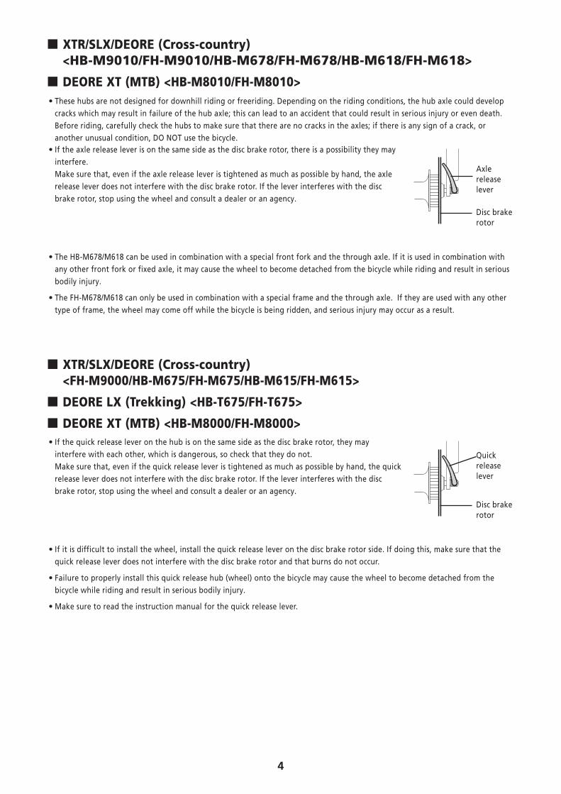
� DEORE XT (MTB) <HB-M8010/FH-M8010> • These hubs are not designed for downhill riding or freeriding. Depending on the riding conditions, the hub axle could develop cracks which may result in failure of the hub axle; this can lead to an accident that could result in serious injury or even death. Before riding, carefully check the hubs to make sure that there are no cracks in the axles; if there is any sign of a crack, or another unusual condition, DO NOT use the bicycle. • If the axle release lever is on the same side as the disc brake rotor, there is a possibility they may interfere. Make sure that, even if the axle release lever is tightened as much as possible by hand, the axle release lever does not interfere with the disc brake rotor. If the lever interferes with the disc brake rotor, stop using the wheel and consult a dealer or an agency.
Axle release lever
Disc brake rotor
• The HB-M678/M618 can be used in combination with a special front fork and the through axle. If it is used in combination with any other front fork or fixed axle, it may cause the wheel to become detached from the bicycle while riding and result in serious bodily injury.
• The FH-M678/M618 can only be used in combination with a special frame and the through axle. If they are used with any other type of frame, the wheel may come off while the bicycle is being ridden, and serious injury may occur as a result.
� XTR/SLX/DEORE (Cross-country) <FH-M9000/HB-M675/FH-M675/HB-M615/FH-M615>
� DEORE LX (Trekking) <HB-T675/FH-T675>
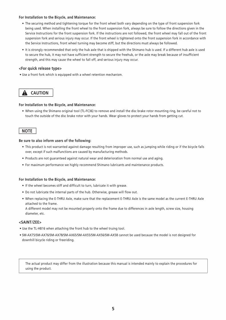
� DEORE XT (MTB) <HB-M8000/FH-M8000> • If the quick release lever on the hub is on the same side as the disc brake rotor, they may interfere with each other, which is dangerous, so check that they do not. Make sure that, even if the quick release lever is tightened as much as possible by hand, the quick release lever does not interfere with the disc brake rotor. If the lever interferes with the disc brake rotor, stop using the wheel and consult a dealer or an agency.
Quick release lever
Disc brake rotor
• If it is difficult to install the wheel, install the quick release lever on the disc brake rotor side. If doing this, make sure that the quick release lever does not interfere with the disc brake rotor and that burns do not occur.
• Failure to properly install this quick release hub (wheel) onto the bicycle may cause the wheel to become detached from the bicycle while riding and result in serious bodily injury.
• Make sure to read the instruction manual for the quick release lever.
5
For Installation to the Bicycle, and Maintenance:
• The securing method and tightening torque for the front wheel both vary depending on the type of front suspension fork being used. When installing the front wheel to the front suspension fork, always be sure to follow the directions given in the Service Instructions for the front suspension fork. If the instructions are not followed, the front wheel may fall out of the front suspension fork and serious injury may occur. If the front wheel is tightened onto the front suspension fork in accordance with the Service Instructions, front wheel turning may become stiff, but the directions must always be followed.
• It is strongly recommended that only the hub axle that is shipped with the Shimano hub is used. If a different hub axle is used to secure the hub, it may not have sufficient strength to secure the freehub, or the axle may break because of insufficient strength, and this may cause the wheel to fall off, and serious injury may occur.
<For quick release type> • Use a front fork which is equipped with a wheel retention mechanism.
CAUTION
For Installation to the Bicycle, and Maintenance:
• When using the Shimano original tool (TL-FC36) to remove and install the disc brake rotor mounting ring, be careful not to touch the outside of the disc brake rotor with your hands. Wear gloves to protect your hands from getting cut.
NOTE
Be sure to also inform users of the following:
• This product is not warranted against damage resulting from improper use, such as jumping while riding or if the bicycle falls over, except if such malfunctions are caused by manufacturing methods.
• Products are not guaranteed against natural wear and deterioration from normal use and aging.
• For maximum performance we highly recommend Shimano lubricants and maintenance products.
For Installation to the Bicycle, and Maintenance:
• If the wheel becomes stiff and difficult to turn, lubricate it with grease.
• Do not lubricate the internal parts of the hub. Otherwise, grease will flow out.
• When replacing the E-THRU Axle, make sure that the replacement E-THRU Axle is the same model as the current E-THRU Axle attached to the frame. A different model may not be mounted properly onto the frame due to differences in axle length, screw size, housing diameter, etc.
<SAINT/ZEE> • Use the TL-HB16 when attaching the front hub to the wheel truing tool.
• SM-AX75/SM-AX76/SM-AX78/SM-AX65/SM-AX55/SM-AX56/SM-AX58 cannot be used because the model is not designed for downhill bicycle riding or freeriding.
The actual product may differ from the illustration because this manual is intended mainly to explain the procedures for using the product.
6
INSTALLATION
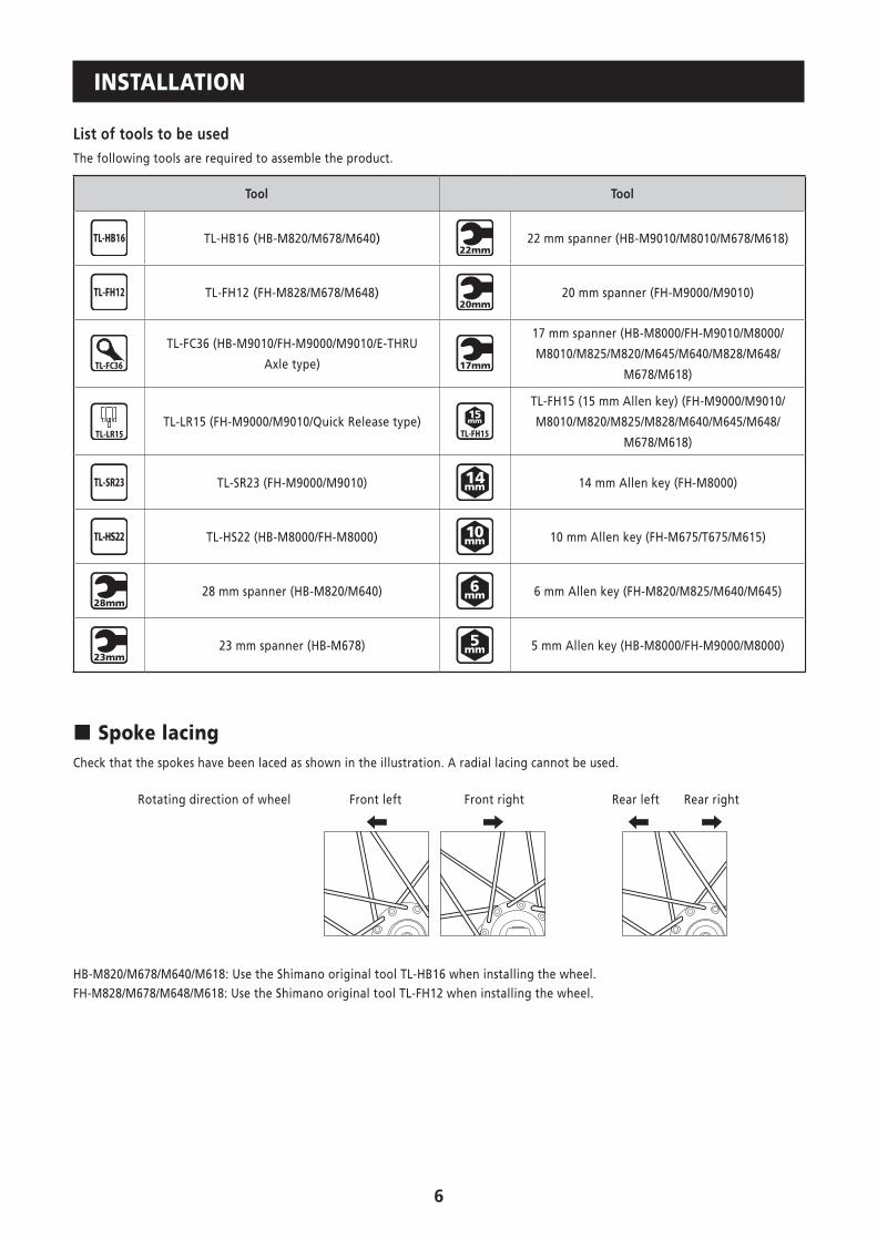
List of tools to be usedThe following tools are required to assemble the product.
Tool Tool
TL-HB16 (HB-M820/M678/M640) 22 mm spanner (HB-M9010/M8010/M678/M618)
TL-FH12 (FH-M828/M678/M648) 20 mm spanner (FH-M9000/M9010)
TL-FC36
TL-FC36 (HB-M9010/FH-M9000/M9010/E-THRU
Axle type)
17 mm spanner (HB-M8000/FH-M9010/M8000/
M8010/M825/M820/M645/M640/M828/M648/
M678/M618)
TL-LR15 (FH-M9000/M9010/Quick Release type)
TL-FH15 (15 mm Allen key) (FH-M9000/M9010/
M8010/M820/M825/M828/M640/M645/M648/
M678/M618)
TL-SR23 (FH-M9000/M9010) 14 mm Allen key (FH-M8000)
TL-HS22 (HB-M8000/FH-M8000) 10 mm Allen key (FH-M675/T675/M615)
28 mm spanner (HB-M820/M640) 6 mm Allen key (FH-M820/M825/M640/M645)
23 mm spanner (HB-M678) 5 mm Allen key (HB-M8000/FH-M9000/M8000)
� Spoke lacingCheck that the spokes have been laced as shown in the illustration. A radial lacing cannot be used.
Rotating direction of wheel Front left Rear leftFront right Rear right
HB-M820/M678/M640/M618: Use the Shimano original tool TL-HB16 when installing the wheel.FH-M828/M678/M648/M618: Use the Shimano original tool TL-FH12 when installing the wheel.
7
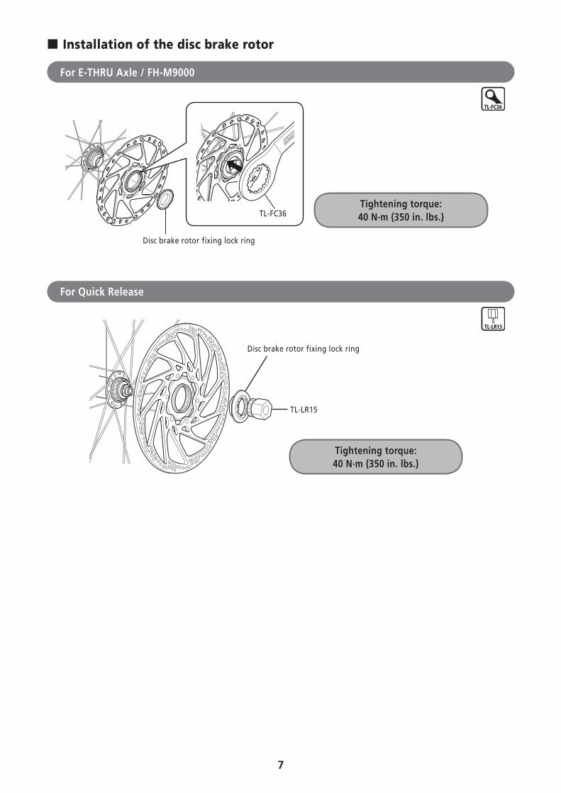
� Installation of the disc brake rotor
For E-THRU Axle / FH-M9000
TL-FC36
Disc brake rotor fixing lock ring
Tightening torque: 40 N·m {350 in. lbs.}
TL-FC36
For Quick Release
Tightening torque: 40 N·m {350 in. lbs.}
Disc brake rotor fixing lock ring
TL-LR15
8
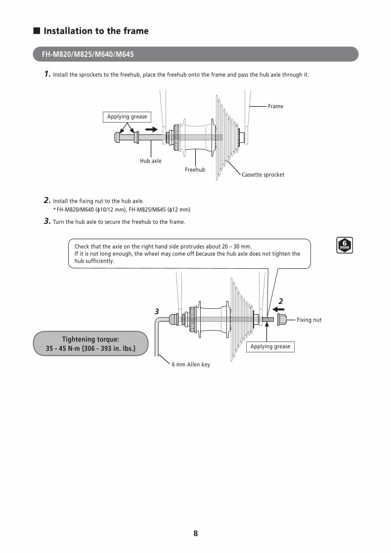
� Installation to the frame
FH-M820/M825/M640/M645
1. Install the sprockets to the freehub, place the freehub onto the frame and pass the hub axle through it.
Frame
FreehubCassette sprocket
Applying grease
Hub axle
2. Install the fixing nut to the hub axle.* FH-M820/M640 (ϕ10/12 mm), FH-M825/M645 (ϕ12 mm)
3. Turn the hub axle to secure the freehub to the frame.
Tightening torque: 35 - 45 N·m {306 - 393 in. lbs.} Applying grease
23
6 mm Allen key
Fixing nut
Check that the axle on the right hand side protrudes about 20 – 30 mm.If it is not long enough, the wheel may come off because the hub axle does not tighten the hub sufficiently.
9
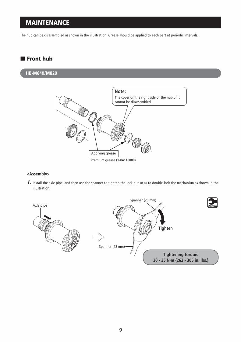
MAINTENANCE
The hub can be disassembled as shown in the illustration. Grease should be applied to each part at periodic intervals.
� Front hub
HB-M640/M820
Note:The cover on the right side of the hub unit cannot be disassembled.
Applying grease
Premium grease (Y-04110000)
<Assembly>
1. Install the axle pipe, and then use the spanner to tighten the lock nut so as to double-lock the mechanism as shown in the illustration.
Axle pipe
Spanner (28 mm)
Tighten
Tightening torque: 30 - 35 N·m {263 - 305 in. lbs.}
Spanner (28 mm)
10
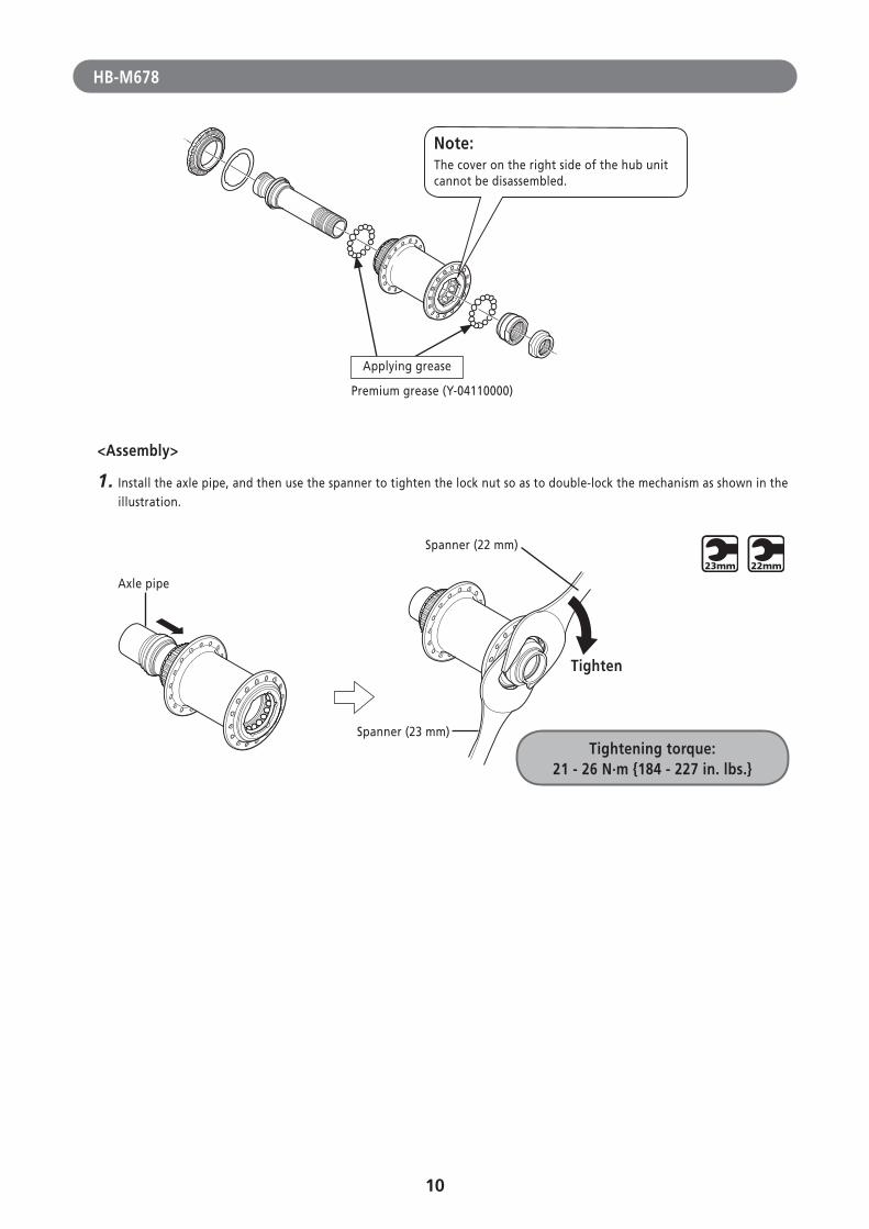
HB-M678
Note:The cover on the right side of the hub unit cannot be disassembled.
Applying grease
Premium grease (Y-04110000)
<Assembly>
1. Install the axle pipe, and then use the spanner to tighten the lock nut so as to double-lock the mechanism as shown in the illustration.
Tightening torque: 21 - 26 N·m {184 - 227 in. lbs.}
Spanner (22 mm)
Axle pipe
Spanner (23 mm)
Tighten
11
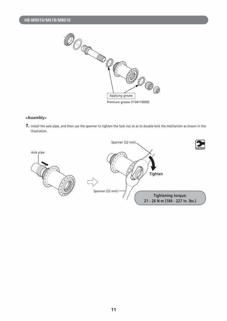
HB-M9010/M618/M8010
Applying grease
Premium grease (Y-04110000)
<Assembly>
1. Install the axle pipe, and then use the spanner to tighten the lock nut so as to double-lock the mechanism as shown in the illustration.
Spanner (22 mm)
Axle pipe
Spanner (22 mm)
Tighten
Tightening torque: 21 - 26 N·m {184 - 227 in. lbs.}
12
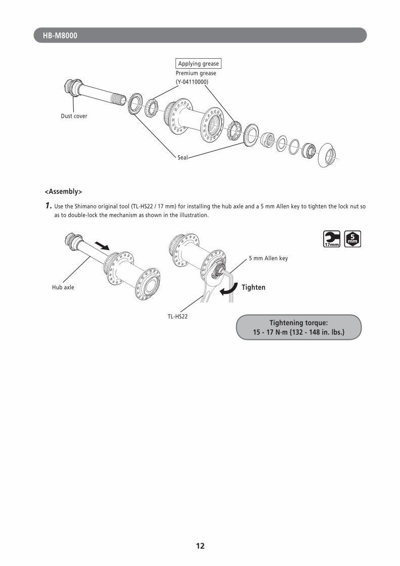
HB-M8000
Applying grease
Premium grease (Y-04110000)
Seal
Dust cover
<Assembly>
1. Use the Shimano original tool (TL-HS22 / 17 mm) for installing the hub axle and a 5 mm Allen key to tighten the lock nut so as to double-lock the mechanism as shown in the illustration.
Tightening torque: 15 - 17 N·m {132 - 148 in. lbs.}
Hub axle
5 mm Allen key
Tighten
TL-HS22
13
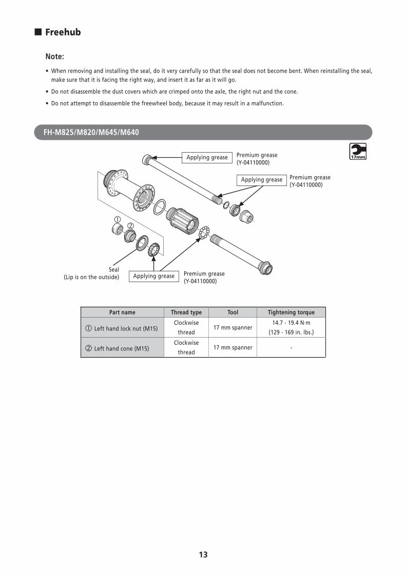
� Freehub
Note:
• When removing and installing the seal, do it very carefully so that the seal does not become bent. When reinstalling the seal, make sure that it is facing the right way, and insert it as far as it will go.
• Do not disassemble the dust covers which are crimped onto the axle, the right nut and the cone.
• Do not attempt to disassemble the freewheel body, because it may result in a malfunction.
FH-M825/M820/M645/M640
Applying grease
Applying grease Premium grease(Y-04110000)
Premium grease(Y-04110000)
Premium grease(Y-04110000)
Seal(Lip is on the outside) Applying grease
Part name Thread type Tool Tightening torque
Left hand lock nut (M15)Clockwise
thread17 mm spanner
14.7 - 19.4 N·m
{129 - 169 in. lbs.}
Left hand cone (M15)Clockwise
thread17 mm spanner -
14
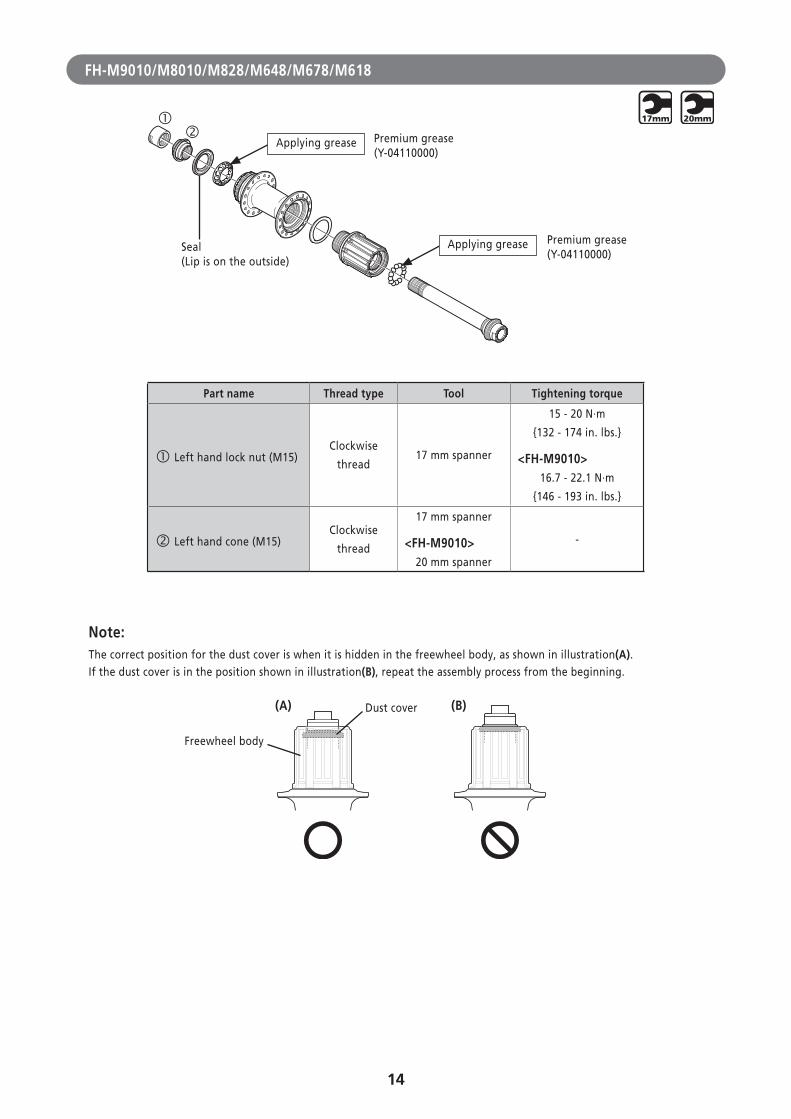
FH-M9010/M8010/M828/M648/M678/M618
Premium grease(Y-04110000)
Premium grease(Y-04110000)
Seal(Lip is on the outside)
Applying grease
Applying grease
Part name Thread type Tool Tightening torque
Left hand lock nut (M15)Clockwise
thread17 mm spanner
15 - 20 N·m
{132 - 174 in. lbs.}
<FH-M9010>16.7 - 22.1 N·m
{146 - 193 in. lbs.}
Left hand cone (M15)Clockwise
thread
17 mm spanner
<FH-M9010>20 mm spanner
-
Note:The correct position for the dust cover is when it is hidden in the freewheel body, as shown in illustration(A).If the dust cover is in the position shown in illustration(B), repeat the assembly process from the beginning.
(A) (B)
Freewheel body
Dust cover
15
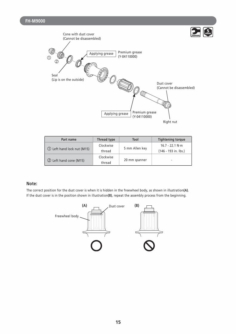
FH-M9000
Cone with dust cover (Cannot be disassembled)
Seal (Lip is on the outside)
Dust cover (Cannot be disassembled)
Right nut
Applying grease Premium grease
(Y-04110000)
Applying grease Premium grease(Y-04110000)
Part name Thread type Tool Tightening torque
Left hand lock nut (M15)Clockwise
thread5 mm Allen key
16.7 - 22.1 N·m
{146 - 193 in. lbs.}
Left hand cone (M15)Clockwise
thread20 mm spanner -
Note:The correct position for the dust cover is when it is hidden in the freewheel body, as shown in illustration(A).If the dust cover is in the position shown in illustration(B), repeat the assembly process from the beginning.
(A) (B)
Freewheel body
Dust cover
16
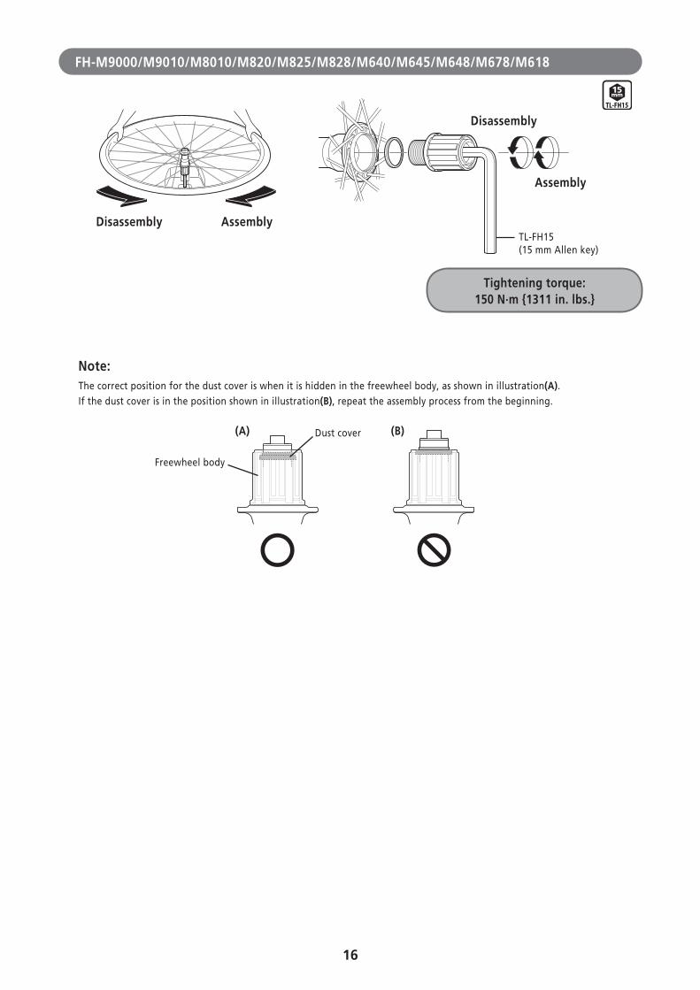
FH-M9000/M9010/M8010/M820/M825/M828/M640/M645/M648/M678/M618
Tightening torque: 150 N·m {1311 in. lbs.}
Disassembly
Assembly
TL-FH15 (15 mm Allen key)
Disassembly Assembly
Note:The correct position for the dust cover is when it is hidden in the freewheel body, as shown in illustration(A).If the dust cover is in the position shown in illustration(B), repeat the assembly process from the beginning.
(A) (B)
Freewheel body
Dust cover
17
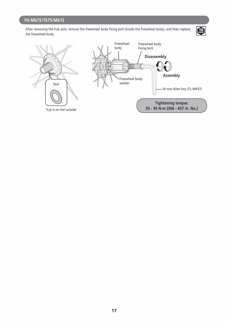
FH-M675/T675/M615
After removing the hub axle, remove the freewheel body fixing bolt (inside the freewheel body), and then replace the freewheel body.
Tightening torque:35 - 50 N·m {306 - 437 in. lbs.}
Disassembly
Assembly
Seal
Freewheel body
Freewheel body fixing bolt
Freewheel body washer
10 mm Allen key (TL-WR37)
*Lip is on the outside
18
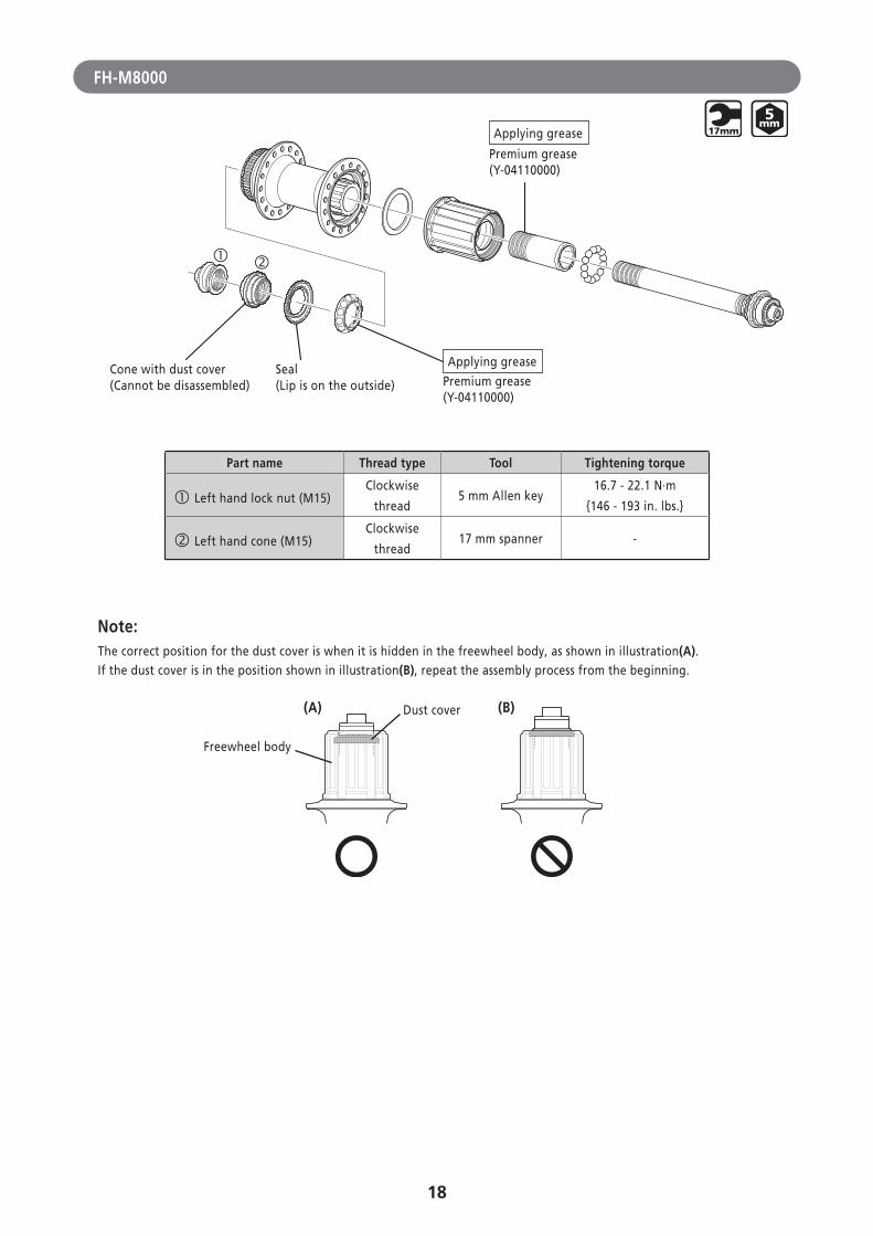
FH-M8000
Applying grease
Premium grease(Y-04110000)
Premium grease(Y-04110000)
Applying greaseSeal(Lip is on the outside)
Cone with dust cover (Cannot be disassembled)
Part name Thread type Tool Tightening torque
Left hand lock nut (M15)Clockwise
thread5 mm Allen key
16.7 - 22.1 N·m
{146 - 193 in. lbs.}
Left hand cone (M15)Clockwise
thread17 mm spanner -
Note:The correct position for the dust cover is when it is hidden in the freewheel body, as shown in illustration(A).If the dust cover is in the position shown in illustration(B), repeat the assembly process from the beginning.
(A) (B)
Freewheel body
Dust cover
19
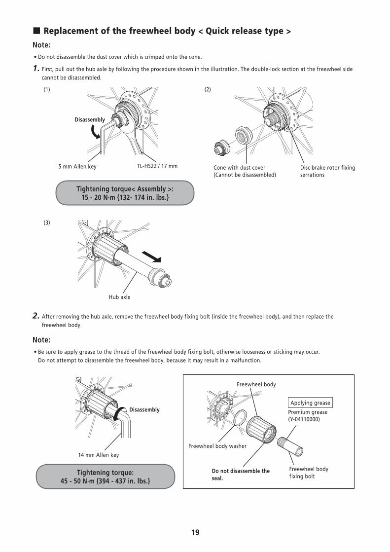
� Replacement of the freewheel body < Quick release type >Note:
• Do not disassemble the dust cover which is crimped onto the cone.
1. First, pull out the hub axle by following the procedure shown in the illustration. The double-lock section at the freewheel side cannot be disassembled.
(1)
Tightening torque< Assembly >: 15 - 20 N·m {132- 174 in. lbs.}
Disassembly
5 mm Allen key TL-HS22 / 17 mm
(2)
Cone with dust cover(Cannot be disassembled)
Disc brake rotor fixing serrations
(3)
Hub axle
2. After removing the hub axle, remove the freewheel body fixing bolt (inside the freewheel body), and then replace the freewheel body.
Note: • Be sure to apply grease to the thread of the freewheel body fixing bolt, otherwise looseness or sticking may occur. Do not attempt to disassemble the freewheel body, because it may result in a malfunction.
Freewheel body
Applying grease
Premium grease(Y-04110000)
Freewheel bodyfixing bolt
Do not disassemble the seal.
Freewheel body washer
Tightening torque: 45 - 50 N·m {394 - 437 in. lbs.}
14 mm Allen key
Disassembly

Please note: specifications are subject to change for improvement without notice. (English) © Feb. 2015 by Shimano Inc. HTR