Embed Size (px)
Citation preview
INSTALLATION INSTRUCTIONS R913
1.0 EXCAVATION AND BEDDING
1.1 The bottom of the excavation shall be covered with a minimum of 12 inches (305 mm) of bedding, suitably graded and lev-eled. Bedding and backfill material surrounding the tank, to a width and depth of 12 inches (305 mm) all around the tank, shall be clean material.
1.2 Steel thickness can be calculated for the required burial depth.
1.3 Where anchoring by means of a concrete pad, the tank shall not be placed directly on the pad. Bedding material at least 6 inches (152.4 mm) deep must be spread evenly over the dimensions of the pad to separate the tank from the pad.
1.4 Bedding and backfill material shall consist of homogenous pea gravel, crushed stone, clean sand, natural earthen materials, or excavatable flowable fill. Crushed stone, clean sand and natural earthen materials shall be capable of passing 100% through a 1/2 inch (13 mm) sieve and no more than 12% by dry weight through a #200 sieve (0.0029 inch (0.0754 mm)). Pea gravel shall be no larger than 3/4-inch (19 mm). Flowable fill shall meet the National Ready Mixed Concrete Association for Controlled Low Strength materials (CLSM) with strength ranging from 70-150 psi and shall be installed in accordance with good engineering practice. The materials shall be free of all foreign materials, such as but not limited to, bricks, metals, concrete and plastics.
1.5 The backfill material may be from the tank site if it meets this description, or it may be delivered to the site from another source.
1.6 Sand or natural earthen materials used as backfill shall be placed into the excavation in 12-18 inch (305-458 mm) vertical lifts, compacted after each lift, at least 60% up the vertical height of the tank.
1.7 If earthen material from the site, or other earthen material, is to be used as bedding or backfill material, a minimum of four 1 cu.ft. samples shall be taken from different locations which are representative of the backfill material and the site. Samples shall be sieved to determine if the material complies with this specification.
1.8 In a tidal area, the tank "bedding" material shall be crushed stone or pea gravel. Sand and natural earthen material may be used only if measures are taken to prevent washout of material during the design life of the system.
2.2 If the manufacturer has shipped a double wall tank with a vacuum on the interstitial space, read and record the vacuum pressure. If the vacuum gauge reading has dropped more than 2 inches Hg (6.77 kPa), from the level at which it was shipped, contact the tank manufacturer.
2.3 To conduct a soap solution/air pressure test, follow these steps: 1. The nylon bushings in the tanks shall not be removed from the
unused openings. Plugs used to temporarily seal the tank for the aboveground air test, but later removed for pipe installation, shall not be over-tightened. Do not cross thread or damage the nylon bushings when replacing plugs or installing required tank
2. Test pressure shall be maintained at, without exceeding, 5 psig (34.5 kPa) while a soap solution is applied to the area of pipe connections and welds.
3. Dual wall tanks require different air pressure testing procedures. Do not connect a high pressure air line directly to the interstitial monitoring port. A factory applied vacuum within the interstitial space can be used in lieu of, or in addition to, the air test procedure. Consult tank fabricator for air test recommendations. Do not apply a vacuum to the primary tank or a single wall tank. PEI/RP 100-00 also provides guidelines.
4. Take necessary safety precautions during air tests. Do not leave tanks unattended while under pressure. Avoid standing at the head of the tank, especially while applying air pressure. Use an air-pressure relief valve.
2.0 AIR TEST AT JOB SITE
2.1 Temporary plugs and thread protectors installed by the manu-facturer shall be removed. Apply compatible, non-hardening pipe sealant to internal bushing threads. Permanent metal plugs shall be installed at all unused openings.
FRP COMPOSITE STEEL
UNDERGROUND STORAGE TANKS
February 2017
2.4 In lieu of the air pressure test described above, a vacuum may be applied to the interstice of a double-wall tank. DO NOT APPLY A VACUUM TO THE PRIMARY TANK OF A DOUBLE-WALL TANK OR TO A SINGLE-WALL TANK. A vacuum of 6 inches Hg (20.3 kPa) is to be applied to the interstice. The vacuum shall be held without a loss for one hour on tanks less than 20,000 gallons and for 2 hours for tanks greater than or equal to 20,000 gallons. If this vacuum cannot be held for the specified time interval, then perform the air test procedure described in section 2.3.
4.0 TANK HANDLING & PREPARATION 4.1 Controlled off-loading of the tank shall be allowed. 4.2 If the tank is fabricated with fiberglass reinforced polyurethane
laminate, it has been delivered with a protective material installed on the tank. This material must remain on the tank and shall not be removed. Before placing the tank in the excavation, all dirt clods and similar foreign matter shall be cleaned from the surface of the tank. Set the tank on the ground such that the protective material is between the tank and the ground.
4.3 Equipment to lift the tank shall be of adequate size to lift and lower the tank without dragging or dropping to prevent damage to the tank or the coating.
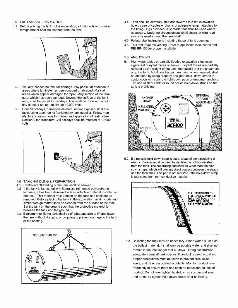
4.4 Tank shall be carefully lifted and lowered into the excavation hole by use of cables or chains of adequate length attached to the lifting lugs provided. A spreader bar shall be used where necessary. Under no circumstances shall chains or wire rope slings be used around the tank shell.
4.5 Follow label instructions including those at tank openings.
4.6 This tank requires venting. Refer to applicable local codes and PEI RP-100 for proper installation.
5.0 ANCHORING
5.1 High water tables or partially flooded excavation sites exert significant buoyant forces on tanks. Buoyant forces are partially resisted by the weight of the tank, the backfill and the pavement atop the tank. Additional buoyant restraint, when required, shall be obtained by using properly designed hold- down straps in conjunction with concrete hold-down pads or deadman anchors. The use of steel cable or round bar as hold-down straps on the tank is prohibited.
3.0 FRP LAMINATE INSPECTION
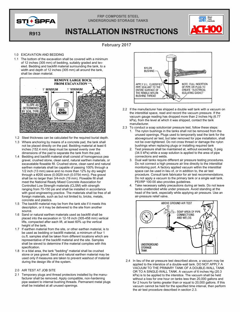
3.1 Before placing the tank in the excavation, all dirt clods and similar foreign matter shall be cleaned from the tank.
5.2 If a metallic hold-down strap is used, a pad of inert insulating di-electric material must be used to insulate the hold-down strap from the tank. The separating pad shall be wider than the hold-sown straps, which will prevent direct contact between the straps and the tank shell. This pad is not required if the hold-down strap is fabricated from non-conductive material.
5.3 Ballasting the tank may be necessary. When water is used as
the ballast material, it shall only be potable water and shall not
remain in the tank longer that 60 days. During construction,
adequately vent all tank spaces. If product is used as ballast,
proper precautions must be taken to prevent fires, spills,
leaks, and other associated accidents. Monitor product level
frequently to ensure there has been no unaccounted loss of
product. Do not over tighten hold-down straps beyond snug
and do not re-tighten hold-down straps after ballasting.
3.2 Visually inspect the tank for damage. Pay particular attention to areas where laminate has been gouged or abraded. Mark all areas which appear damaged for repair. Any section of the lami-nate, which has been damaged beyond the surface of the lami-nate, shall be tested for holidays. This shall be done with a holi-day detector set at a minimum 10,000 volts.
3.3 Coat all holidays, damaged laminate, and/or exposed steel sur-faces using touch-up kit furnished by tank supplier. Follow man-ufacturer's instructions for mixing and application of resin. (See Section 9 for procedure.) All holidays shall be retested at 10,000 volts.
8.2 If the tank is to be installed near an impressed current system, the effect of the system must be considered on the ACT-100® tank. The corrosion consultant must consider including the ACT-100® tank into the design of the impressed current system.
7.0 FINAL AIR TEST
7.1 Install required tank piping using compatible non-hardening sealant, taking care not to cross thread or damage the non-metallic bushings. Torque of 400 to 1,000 ft-lbs (542.3 to 1355.8 N-m) may be required to fully insert pipe.
7.2 Where air or hydrostatic testing is required after installation, the pressure applied shall not be in excess of 5 pounds per-square-inch (34.5 kPa) as measured at the top of the tank. A soap solution shall be applied around pipe connectors while air test is being performed.
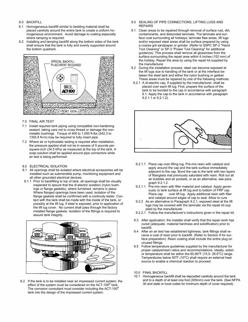
6.0 BACKFILL
6.1 Homogeneous backfill similar to bedding material shall be placed carefully around the entire tank to create a uniform ho-mogeneous environment. Avoid damage to coating especially where tamping is required.
6.2 Installing and tamping backfill along the bottom sides of the tank shall ensure that the tank is fully and evenly supported around the bottom quadrant.
8.0 ELECTRICAL ISOLATION 8.1 All openings shall be isolated where electrical accessories will be
installed such as submersible pump, monitoring equipment and all other grounded electrical devices.
8.1.1 Prior to backfilling to top of tank, all openings shall be visually inspected to assure that the di-electric isolation (nylon bush-ings or flange gaskets), where furnished, remains in place. Where flanged openings have been used, isolation of the flange gaskets shall be confirmed with a continuity tester. Con-tact with the tank shall be made with the inside of the tank, or possibly at the lift lug, if steel is exposed, prior to application of the lift lug cover. No current shall pass through the factory installed flange gaskets. Isolation of the fittings is required to assure tank integrity.
9.0 SEALING OF PIPE CONNECTIONS, LIFTING LUGS AND REPAIRS
9.1 Clean areas to be repaired through removal of surface rust, dirt, contaminants, and disbonded laminate. The laminate and sur-face coat surrounding all holidays, laminate flaw areas, lift lugs and/or exposed steel areas shall be surface prepared by using a coarse grit sandpaper or grinder. (Refer to SSPC SP-2 "Hand Tool Cleaning" or SP-3 "Power Tool Cleaning" for additional guidance). This process shall remove all glossiness from the surface surrounding the repair area within 6 inches (152 mm) of the holiday. Repair the area by using the repair kit supplied by the manufacturer.
9.2 During the installation process, steel can become exposed at the lift lugs due to handling of the tank or at the interface be-tween the steel tank and either the nylon bushing or gasket. These areas must be repaired by one of the following methods.
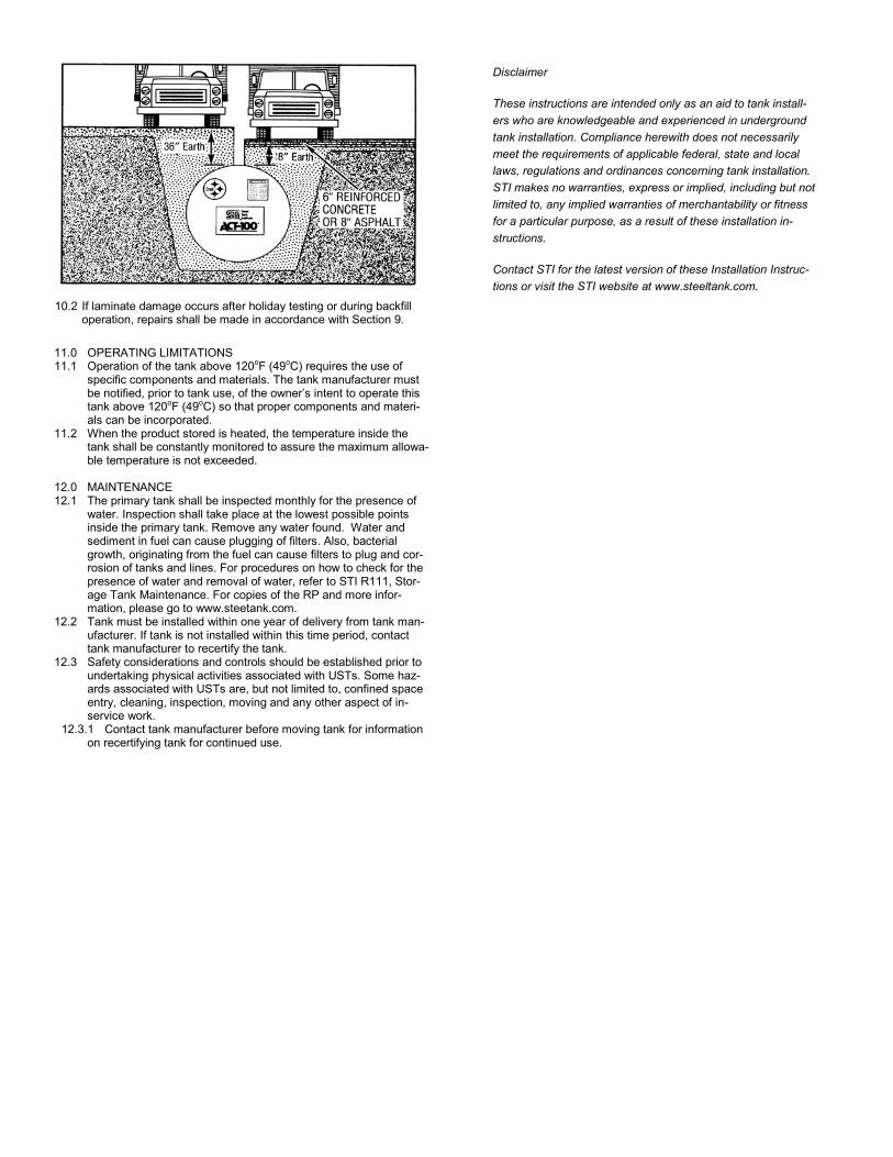
9.2.1 A di-electric cap, if supplied by the manufacturer, shall be placed over each lift lug. First, prepare the surface of the tank to be bonded to the cap in accordance with paragraph 9.1. Apply the cap to the tank in accordance with paragraph 9.2.1.1 or 9.2.1.2).
9.2.1.1 Place cap over lifting lug. Pre-mix resin with catalyst and apply around the cap and the tank surface immediately adjacent to the cap. Bond the cap to the tank with two layers of fiberglass mat previously saturated with resin. Roll out all air bubbles and air pockets, or as an alternative, see para-graph 9.2.1.2.
9.2.1.1 Pre-mix resin with filler material and catalyst. Apply gener-ously to tank surface at lift lug and to bottom of FRP cap. Place cap over lift lug. Apply additional resin with filler and catalyst around edges of cap to seal. Allow to cure.
9.2.2 As an alternative to Paragraph 9.2.1, exposed steel at the lift lugs may be covered with the laminate via the repair kit sup plied by the manufacturer.
9.2.2.1 Follow the manufacturer’s instructions given in the repair kit. 9.3 After application, the installer shall verify that the repair work has
cured (adequate material hardness and solidification) prior to backfill.
9.4 After an air test has established tightness, tank fittings shall re-ceive a coat of resin prior to backfill. (Refer to Section 9 for sur-face preparation). Resin coating shall include the entire plug on unused fittings.
9.5 Follow temperature guidelines supplied by the manufacturer for proper catalyst/resin ratios and recommendations. Ideally, exteri-or temperature shall be within the 60-80oF (15.5- 26.6oC) range. Temperatures below 50oF (10oC) shall require an external heat source to enable a chemical reaction to proceed.
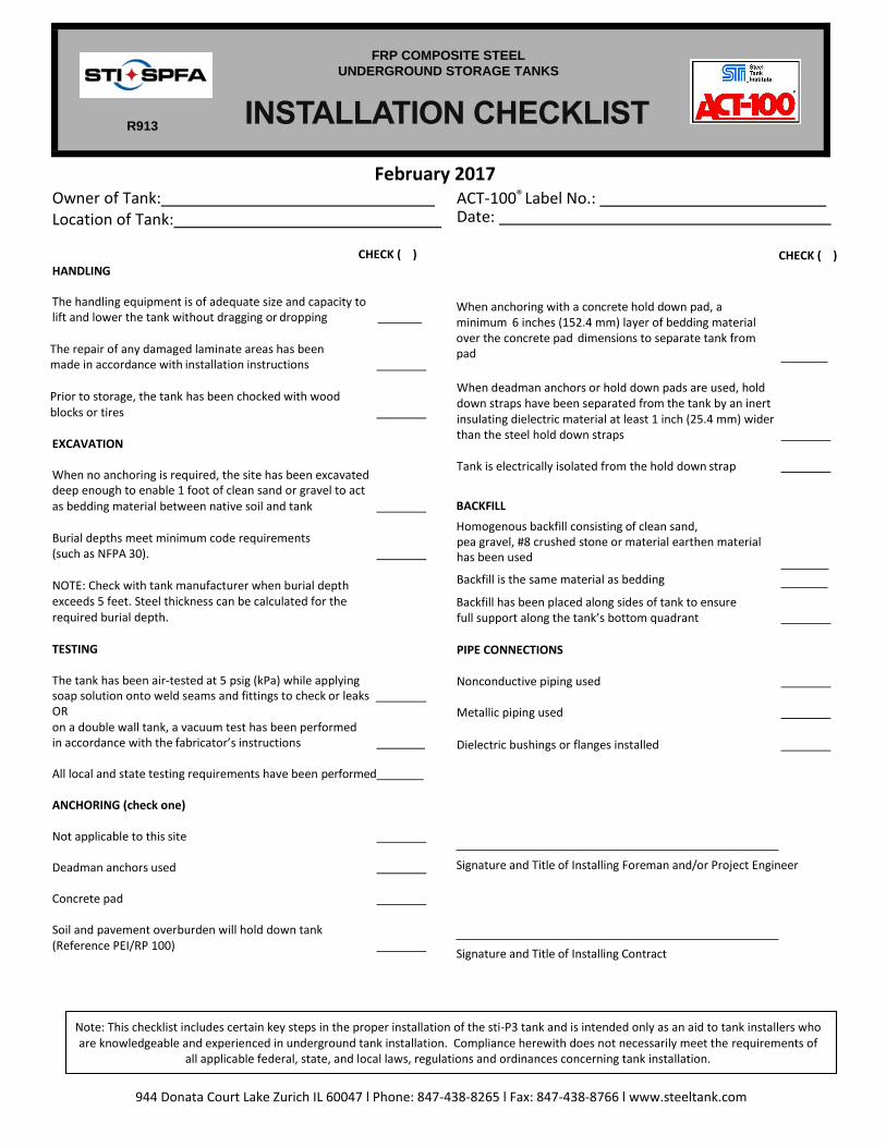
10.0 FINAL BACKFILL 10.1 Homogeneous backfill shall be deposited carefully around the tank
and to a depth of at least one foot (305mm) over the tank. (See NFPA 30 and state or local codes for minimum depth of cover required).
10.2 If laminate damage occurs after holiday testing or during backfill operation, repairs shall be made in accordance with Section 9.
Disclaimer
These instructions are intended only as an aid to tank install-
ers who are knowledgeable and experienced in underground
tank installation. Compliance herewith does not necessarily
meet the requirements of applicable federal, state and local
laws, regulations and ordinances concerning tank installation.
STI makes no warranties, express or implied, including but not
limited to, any implied warranties of merchantability or fitness
for a particular purpose, as a result of these installation in-
structions.
Contact STI for the latest version of these Installation Instruc-
tions or visit the STI website at www.steeltank.com.
11.0 OPERATING LIMITATIONS 11.1 Operation of the tank above 120oF (49oC) requires the use of
specific components and materials. The tank manufacturer must be notified, prior to tank use, of the owner’s intent to operate this tank above 120oF (49oC) so that proper components and materi-als can be incorporated.
11.2 When the product stored is heated, the temperature inside the tank shall be constantly monitored to assure the maximum allowa-ble temperature is not exceeded.
12.0 MAINTENANCE 12.1 The primary tank shall be inspected monthly for the presence of
water. Inspection shall take place at the lowest possible points inside the primary tank. Remove any water found. Water and sediment in fuel can cause plugging of filters. Also, bacterial growth, originating from the fuel can cause filters to plug and cor-rosion of tanks and lines. For procedures on how to check for the presence of water and removal of water, refer to STI R111, Stor-age Tank Maintenance. For copies of the RP and more infor-mation, please go to www.steetank.com.
12.2 Tank must be installed within one year of delivery from tank man-ufacturer. If tank is not installed within this time period, contact tank manufacturer to recertify the tank.
12.3 Safety considerations and controls should be established prior to undertaking physical activities associated with USTs. Some haz-ards associated with USTs are, but not limited to, confined space entry, cleaning, inspection, moving and any other aspect of in-service work.
12.3.1 Contact tank manufacturer before moving tank for information on recertifying tank for continued use.
944 Donata Court Lake Zurich IL 60047 l Phone: 847-438-8265 l Fax: 847-438-8766 l www.steeltank.com
February 2017 Owner of Tank: Location of Tank:
ACT-100® Label No.: Date:
HANDLING
CHECK ( ) CHECK ( )
The handling equipment is of adequate size and capacity to lift and lower the tank without dragging or dropping The repair of any damaged laminate areas has been made in accordance with installation instructions
Prior to storage, the tank has been chocked with wood blocks or tires
EXCAVATION When no anchoring is required, the site has been excavated deep enough to enable 1 foot of clean sand or gravel to act as bedding material between native soil and tank Burial depths meet minimum code requirements (such as NFPA 30). NOTE: Check with tank manufacturer when burial depth exceeds 5 feet. Steel thickness can be calculated for the required burial depth. TESTING The tank has been air-tested at 5 psig (kPa) while applying soap solution onto weld seams and fittings to check or leaks OR on a double wall tank, a vacuum test has been performed in accordance with the fabricator’s instructions
All local and state testing requirements have been performed
ANCHORING (check one) Not applicable to this site Deadman anchors used Concrete pad Soil and pavement overburden will hold down tank (Reference PEI/RP 100)
When anchoring with a concrete hold down pad, a minimum 6 inches (152.4 mm) layer of bedding material over the concrete pad dimensions to separate tank from pad When deadman anchors or hold down pads are used, hold down straps have been separated from the tank by an inert insulating dielectric material at least 1 inch (25.4 mm) wider than the steel hold down straps Tank is electrically isolated from the hold down strap
BACKFILL
Homogenous backfill consisting of clean sand, pea gravel, #8 crushed stone or material earthen material has been used
Backfill is the same material as bedding
Backfill has been placed along sides of tank to ensure full support along the tank’s bottom quadrant PIPE CONNECTIONS Nonconductive piping used Metallic piping used Dielectric bushings or flanges installed
Signature and Title of Installing Foreman and/or Project Engineer
Signature and Title of Installing Contract
INSTALLATION CHECKLIST
FRP COMPOSITE STEEL
UNDERGROUND STORAGE TANKS
R913
Note: This checklist includes certain key steps in the proper installation of the sti-P3 tank and is intended only as an aid to tank installers who are knowledgeable and experienced in underground tank installation. Compliance herewith does not necessarily meet the requirements of
all applicable federal, state, and local laws, regulations and ordinances concerning tank installation.