Embed Size (px)
Citation preview
FIBERGLASS STORAGE TANK I N S TA L L AT I O N I N S T R U C T I O N S & O P E R AT I N G G U I D E L I N E S
P E T R O L E U M T A N K SF L O W T I T E ® W AT E R T A N K SO I L / W AT E R S E P A R AT O R SC H E M I C A L T A N K S
VERSION
J05/15
2
FIBERGLASS TANK INSTALLATION INSTRUCTIONS
Table of Contents
1. Introduction .......................................................................3
1.6 Safety ......................................................................................3 1.7 Important Information .....................................................3 1.8 Important Reminders .......................................................3 1.9 Tank Limited Warranty Activation ...............................3 1.10 Before You Begin ...............................................................4
2. Handling/Storage .............................................................4
2.2 To Avoid Tank Damage....................................................5 2.3 Lifting Tanks .........................................................................5 2.4 Lifting CSI Deadmen .........................................................5 2.5 Lifting Tank Sumps or Risers ..........................................6
3. Bed and Backfi ll .................................................................6
4. Pre-Installation Testing ....................................................6
4.2 Visual Air/Soap Test ..........................................................6 4.3 Prepare for Testing ............................................................7
5. Testing Tanks .....................................................................8
5.1 Testing Single-Wall Tanks ...............................................8 5.2 Double-Wall Tanks Shipped Under Vacuum............8 5.3 Testing Double-Wall Tanks with Dry Annular Space ...................................................8 5.4 Testing Double-Wall Compartment Tanks with a Dry Annular Space and Double-Wall Bulkheads ...................................................9 5.5 Testing Double-Wall Tanks with Liquid Filled Annular Space (Hydrostatically Monitored) ........................................ 10 5.6 Testing Double-Wall Compartment Tanks with Double-Wall Bulkheads (Hydrostatically Monitored) ........................................ 10 5.7 For Tanks That Cannot Be Air Tested ....................... 11
6. Excavation and Tank Clearance .................................. 12 6.1 Stable Excavations .......................................................... 12 6.2 Unstable Excavations .................................................... 12 6.3 Shoring Removal ............................................................. 13 6.4 Tank Location - Nearby Structures ........................... 13
7. Geotextile Fabric ............................................................ 13
7.2 Geotextile Fabrics Are Required for any of the Following Locations ........................... 13 7.6 Geotextile Fabric Installation ...................................... 13
8. Burial Depth and Cover ................................................. 14 8.3 Minimum Burial Depth - No Traffi c Load ................ 14 8.4 Minimum Burial Depth - Traffi c Load ...................... 14
9. Anchoring ........................................................................ 15 9.7 General Anchoring Requirements ............................ 15 9.8 Anchor Point Loads ........................................................ 15 9.9 Standard Eye by Eye Hold Down Strap ................... 16
9.11 Drop-Forged Turnbuckles ........................................... 16 9.12 Wire Rope .......................................................................... 16 9.13 Deadmen Anchors .......................................................... 16 9.14 Concrete Anchor Pad .................................................... 17 9.15 Split Strap Anchoring System ..................................... 17
10. Ballasting Tanks ............................................................ 18
11. Tank Installation ........................................................... 18
11.1 Before You Begin ............................................................ 18 11.2 Tank Vertical Diameter Measurements ................... 18 11.3 Installation Procedure ................................................... 19 11.4 Backfi ll To Subgrade ...................................................... 20
12. Adding Tanks at Existing Locations .......................... 21
12.2 Preferred Method ........................................................... 21 12.3 Alternate Method for Dry Hole Excavation ........... 21
13. Piping and Bottom Sump Clearances ....................... 22
13.1 Tanks with Bottom Sumps / Fittings ........................ 22 13.2 External Piping ................................................................. 22
14. Venting ........................................................................... 22
15. Filling Tanks................................................................... 22
16. Manways ........................................................................ 22
17. Annular Space Monitoring ......................................... 23
17.1 Hydrostatic Monitoring ................................................ 23 17.3 Dry Annular Space Monitoring with Sensor .......... 23 17.4 Dry Annular Space Vacuum or Air Pressure Monitoring .......................................... 24
18. Containment Collars, Tank Sumps & Tank Risers ... 24
18.3 All Tanks & Sumps ........................................................... 24 18.4 Collar Test Instructions ................................................. 2419. Operating Guidelines .................................................. 25
19.1 General ............................................................................... 25 19.2 Fiberglass Tanks Intended Use .................................. 25 19.3 Confi ned Space Entry .................................................... 25 19.4 Filling / Venting Tanks (General) ............................... 25 19.12 Containment Sumps, Manway Extensions & Access Risers ................................................................. 2620. Conversion Formulas ................................................... 26
21. Supplemental Documents .......................................... 26
Appendix
App A. Anchor Chart ..............................................................27-28
App B. Standard Tank Sizes ....................................................... 29
Tank Installation Checklist .............................................30-31
Tank Technical Support
Conroe, Texas
(800) 537-4730 • (936) 756-7731
Field Service Department
Mt. Union, Pennsylvania
(800) 822-1997 • (814) 542-8520
3
INTRODUCTION / IMPORTANT INFORMATION
1. INTRODUCTION
1.1. The purpose of this manual is to provide specifiers, owners and contractors with detailed instructions for installing and operating Containment Solutions, Inc. (CSI) single and double-wall fiberglass underground storage tanks and oil/water separators.
1.2. CSI Tank installation is a specialized business. If you do not have the proper experience and have not completed CSI training for tank installation in the last 24 months, please contact a trained contractor or call CSI for a list of trained contractors.
1.3. These instructions have been developed and refined from the experience of over 300,000tank installations.
1.4. Proper installation is required to assure thelong-term performance of CSI Storage Tanks. These instructions must be followed. Failure to comply will void the limited warranty and may cause tank failure.
1.5. It is the responsibility of the owner, installer and operator to understand and follow all installation requirements.
1.6. Safety1.6.1. These instructions should not be interpreted
in any way to put one’s health at risk, or to harm property and/or the environment.
1.6.2. Keep this manual available at the installation site and refer to safety procedures as needed.
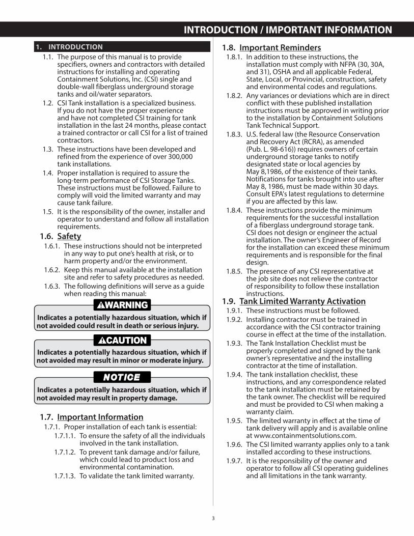
1.6.3. The following definitions will serve as a guide when reading this manual:
1.7. Important Information1.7.1. Proper installation of each tank is essential:
1.7.1.1. To ensure the safety of all the individuals involved in the tank installation.
1.7.1.2. To prevent tank damage and/or failure, which could lead to product loss and environmental contamination.
1.7.1.3. To validate the tank limited warranty.
Indicates a potentially hazardous situation, which if not avoided could result in death or serious injury.
Indicates a potentially hazardous situation, which if not avoided may result in minor or moderate injury.
Indicates a potentially hazardous situation, which if not avoided may result in property damage.
1.8. Important Reminders1.8.1. In addition to these instructions, the
installation must comply with NFPA (30, 30A, and 31), OSHA and all applicable Federal, State, Local, or Provincial, construction, safety and environmental codes and regulations.
1.8.2. Any variances or deviations which are in direct conflict with these published installation instructions must be approved in writing prior to the installation by Containment Solutions Tank Technical Support.
1.8.3. U.S. federal law (the Resource Conservation and Recovery Act (RCRA), as amended (Pub. L. 98-616)) requires owners of certain underground storage tanks to notify designated state or local agencies byMay 8,1986, of the existence of their tanks. Notifications for tanks brought into use after May 8, 1986, must be made within 30 days. Consult EPA's latest regulations to determineif you are affected by this law.
1.8.4. These instructions provide the minimum requirements for the successful installation of a fiberglass underground storage tank. CSI does not design or engineer the actual installation. The owner’s Engineer of Record for the installation can exceed these minimum requirements and is responsible for the final design.
1.8.5. The presence of any CSI representative at the job site does not relieve the contractor of responsibility to follow these installation instructions.
1.9. Tank Limited Warranty Activation1.9.1. These instructions must be followed.1.9.2. Installing contractor must be trained in
accordance with the CSI contractor training course in effect at the time of the installation.
1.9.3. The Tank Installation Checklist must be properly completed and signed by the tank owner’s representative and the installing contractor at the time of installation.
1.9.4. The tank installation checklist, these instructions, and any correspondence related to the tank installation must be retained by the tank owner. The checklist will be required and must be provided to CSI when making a warranty claim.
1.9.5. The limited warranty in effect at the time of tank delivery will apply and is available online at www.containmentsolutions.com.
1.9.6. The CSI limited warranty applies only to a tank installed according to these instructions.
1.9.7. It is the responsibility of the owner and operator to follow all CSI operating guidelines and all limitations in the tank warranty.
4
1.10. Before You Begin1.10.1. Read, understand and follow these
instructions.1.10.2. Barricade the tank area until the job is
completed.1.10.3. Review and prepare to complete the
installation checklist.1.10.4. Check with local authorities for building
codes, underground utilities and testing requirements.
1.10.5. If you have installation questions or need alternate installation methods, contact CSI Tank Technical Support.
1.10.6. If you have other questions regarding tank modifications, such as adding fittings or manways or tank repair, contact Containment Solutions Field Services.
1.10.7. A list of supplemental documents is found inSection 21.
2. HANDLING & STORAGE
2.1. Common Terms for:2.1.1. Petroleum Tanks (see Figure 2-1).
ASPHYXIATION FIRE EXPLOSION
Do not enter tank or sumps unless following OSHA guidelines for confined space entry. Failure to follow OSHA guidelines could result in death or serious injury.
Figure 2-1
Lift Lug Annular Space FittingAnchor StrapLocationArrows
Rib
Monitoring FluidReservoir
Bulkhead
ContainmentCollar
Endcap
Manway & Coverw / fittings
Primary Tank Fitting
Rib Section
ExtensionMainTank
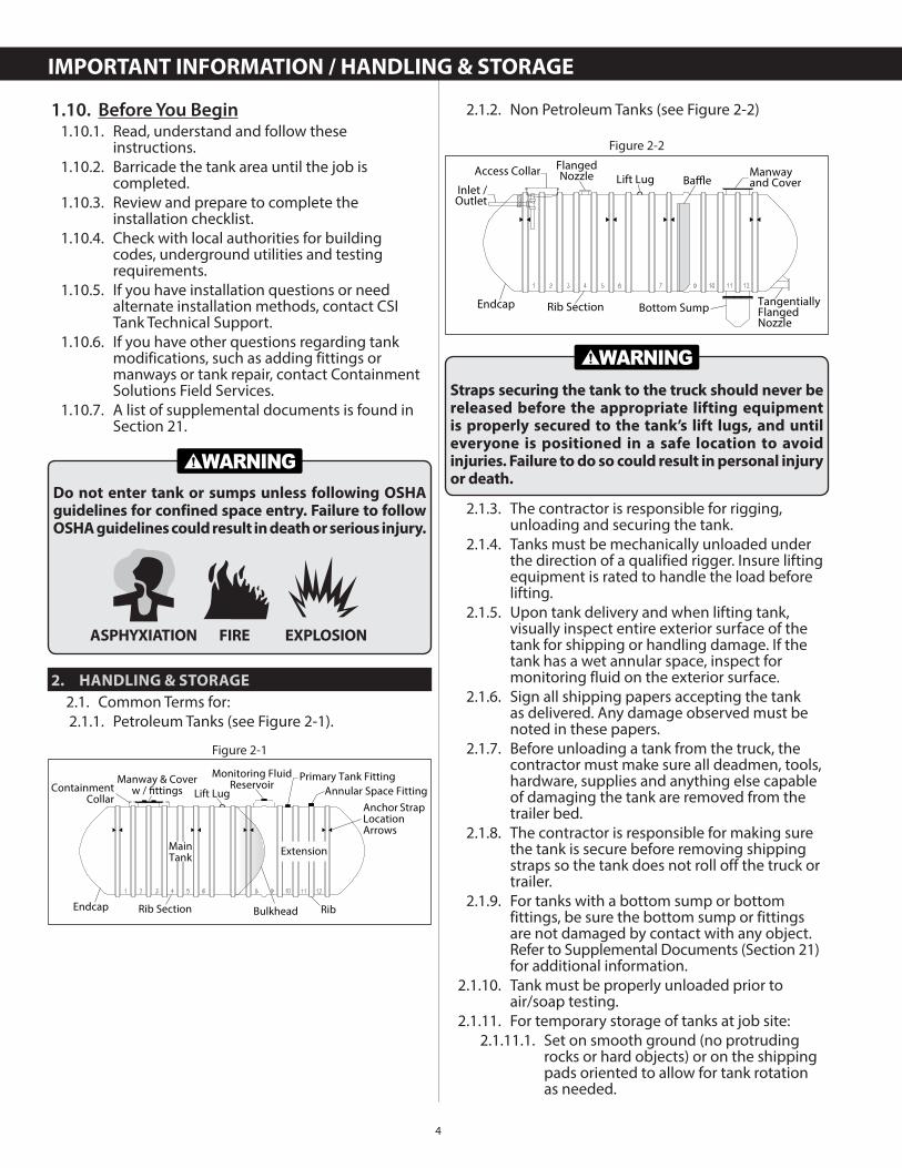
2.1.2. Non Petroleum Tanks (see Figure 2-2)
2.1.3. The contractor is responsible for rigging, unloading and securing the tank.
2.1.4. Tanks must be mechanically unloaded under the direction of a qualified rigger. Insure lifting equipment is rated to handle the load before lifting.
2.1.5. Upon tank delivery and when lifting tank, visually inspect entire exterior surface of the tank for shipping or handling damage. If the tank has a wet annular space, inspect for monitoring fluid on the exterior surface.
2.1.6. Sign all shipping papers accepting the tank as delivered. Any damage observed must be noted in these papers.
2.1.7. Before unloading a tank from the truck, the contractor must make sure all deadmen, tools, hardware, supplies and anything else capable of damaging the tank are removed from the trailer bed.
2.1.8. The contractor is responsible for making sure the tank is secure before removing shipping straps so the tank does not roll off the truck or trailer.
2.1.9. For tanks with a bottom sump or bottom fittings, be sure the bottom sump or fittings are not damaged by contact with any object. Refer to Supplemental Documents (Section 21) for additional information.
2.1.10. Tank must be properly unloaded prior toair/soap testing.
2.1.11. For temporary storage of tanks at job site:2.1.11.1. Set on smooth ground (no protruding
rocks or hard objects) or on the shipping pads oriented to allow for tank rotation as needed.
Figure 2-2
Lift LugFlangedNozzle Manway
and CoverBaffleAccess Collar
Inlet /Outlet
Bottom Sump TangentiallyFlangedNozzle
Endcap Rib Section
Straps securing the tank to the truck should never be released before the appropriate lifting equipment is properly secured to the tank’s lift lugs, and until everyone is positioned in a safe location to avoid injuries. Failure to do so could result in personal injury or death.
IMPORTANT INFORMATION / HANDLING & STORAGE
5
2.1.11.2. Chock with sandbags.2.1.11.3. If high winds are anticipated, tie the tank
down to prevent damage. Do not use wire ropes or chains, and do not place straps over collars or reservoirs.
2.1.11.4. When the tank must be rolled for air/soap test, roll only on shipping pads or smooth surface free of protruding rocks or hard objects. Ensure fittings and/or collars do not come in contact with the ground.
2.1.11.5. Protect collars from water accumulation in freezing conditions or tank damage may occur.
2.2. To Avoid Tank Damage2.2.1. Do not allow tank to rotate or swing during
unloading.2.2.2. Do not use chains or cables around tanks.2.2.3. Do not allow metal hardware to contact the
tank.2.2.4. Do not allow fittings, collars, manways,
reservoirs, or any accessory to contactground during rotation.
2.2.5. Do not drop tank.2.3. Lifting Tanks
2.3.1. To lift the tank, always use the number of lift lugs indicated on the label adjacent to the lift lugs. Apply equal tension to all lift lugs simultaneously. Slings may also be used to lift the tank. Refer to Supplemental Documents (Section 21) for additional information.Slings around the tank must be used if the tank is to be handled in a non-level or angled position.
2.3.2. Tanks may be provided with guide lugs for attachment of guide ropes during lifting and positioning operations. Do not use guide lugs for lifting.
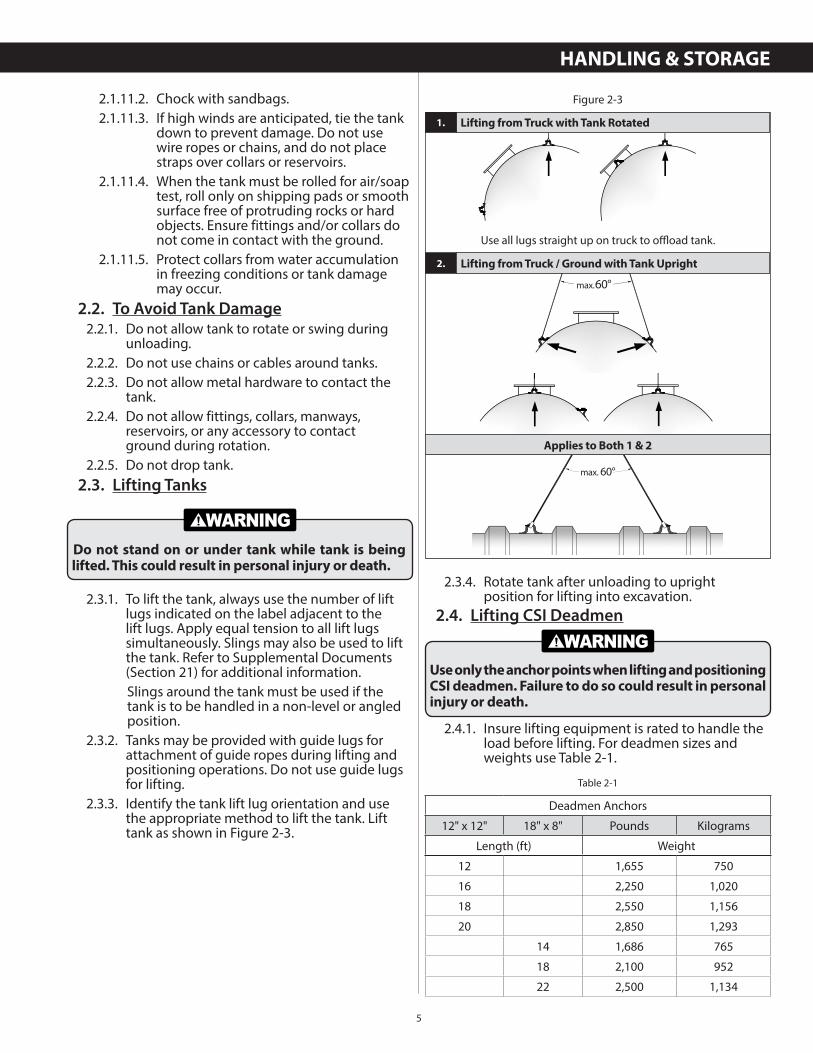
2.3.3. Identify the tank lift lug orientation and use the appropriate method to lift the tank. Lift tank as shown in Figure 2-3.
Do not stand on or under tank while tank is being lifted. This could result in personal injury or death.
2.3.4. Rotate tank after unloading to upright position for lifting into excavation.
2.4. Lifting CSI Deadmen
2.4.1. Insure lifting equipment is rated to handle the load before lifting. For deadmen sizes and weights use Table 2-1.
Lifting from Truck with Tank Rotated
2.
max. 60°max. 60°
Lifting from Truck / Ground with Tank Upright
max. 60°
Figure 2-3
Use all lugs straight up on truck to offl oad tank.
1.
max. 60°
max. 60°max. 60°
Use only the anchor points when lifting and positioning CSI deadmen. Failure to do so could result in personal injury or death.
Deadmen Anchors
12" x 12" 18" x 8" Pounds Kilograms
Length (ft) Weight
12 1,655 750
16 2,250 1,020
18 2,550 1,156
20 2,850 1,293
14 1,686 765
18 2,100 952
22 2,500 1,134
Table 2-1
HANDLING & STORAGE
Applies to Both 1 & 2
6
2.4.2. Lift deadman using a minimum of two equally spaced anchor points (see Figure 2-4).
2.4.3. The deadmen type, lengths, and the number of anchor points are dependent upon the tank diameter, model and capacity. See customer specific drawing for deadman placement and anchoring location details.
2.5. Lifting Tank Sumps or Risers2.5.1. Visually inspect the sump components for
shipping damage. If damage is found, contact CSI Field Services.
2.5.2. Wear gloves.2.5.3. Do not roll, drop or bounce.2.5.4. Set on smooth surface.2.5.5. The sump must be secured to prevent damage
from high winds. Proper precautions should be taken to protect adhesive channels.
2.5.6. Refer to Supplemental Documents (Section 21) for additional information on tank sumps.
3. BED & BACKFILL
3.1. The use of approved backfill material is critical to long term tank performance.
3.2. Do not mix approved backfill with sand or native soil.
3.3. Do not backfill tank with sand or native soil.3.3.1. Replace all excavated native soil with
approved backfill of proper size and gradation. Use backfill which meets ASTM C-33 for quality and soundness.
3.3.2. Require your backfill supplier to certify, with a sieve analysis, that the backfill meets this specification.
3.3.3. Sieve analysis must be attached to the Tank Installation Checklist.
3.3.4. Keep backfill dry and free of ice in freezing conditions.
Lifting Chain or SlingAnchor Pointmax.60°
Figure 2-4
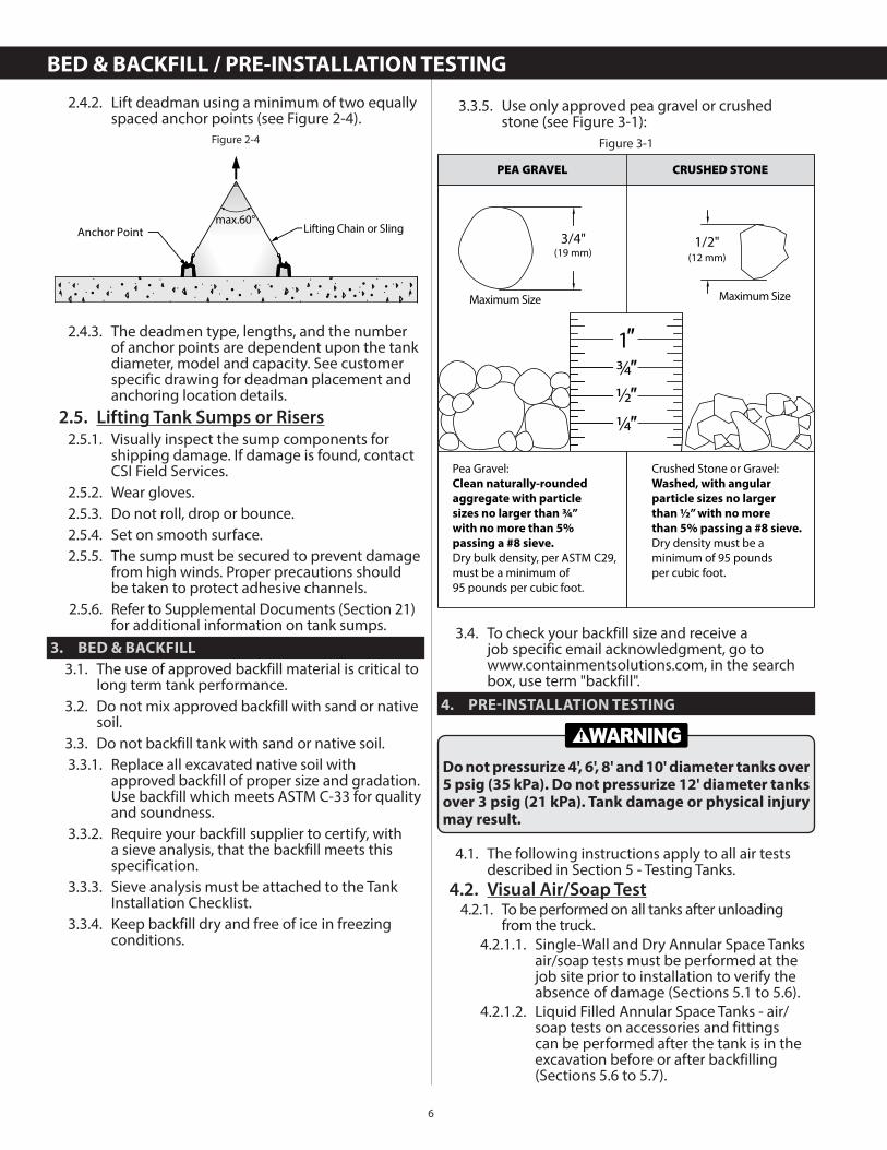
3.3.5. Use only approved pea gravel or crushed stone (see Figure 3-1):
3.4. To check your backfill size and receive ajob specific email acknowledgment, go towww.containmentsolutions.com, in the search box, use term "backfill".
4. PRE-INSTALLATION TESTING
4.1. The following instructions apply to all air tests described in Section 5 - Testing Tanks.
4.2. Visual Air/Soap Test4.2.1. To be performed on all tanks after unloading
from the truck.4.2.1.1. Single-Wall and Dry Annular Space Tanks
air/soap tests must be performed at the job site prior to installation to verify the absence of damage (Sections 5.1 to 5.6).
4.2.1.2. Liquid Filled Annular Space Tanks - air/soap tests on accessories and fittings can be performed after the tank is in the excavation before or after backfilling (Sections 5.6 to 5.7).
Figure 3-1
3/4"(19 mm)
Maximum Size
1/2"(12 mm)
Maximum Size
1″
½″¼″
¾″
Pea Gravel:Clean naturally-rounded
aggregate with particle
sizes no larger than ¾”
with no more than 5%
passing a #8 sieve.
Dry bulk density, per ASTM C29,must be a minimum of95 pounds per cubic foot.
Crushed Stone or Gravel:Washed, with angular
particle sizes no larger
than ½” with no more
than 5% passing a #8 sieve.
Dry density must be a minimum of 95 poundsper cubic foot.
PEA GRAVEL CRUSHED STONE
Do not pressurize 4', 6', 8' and 10' diameter tanks over 5 psig (35 kPa). Do not pressurize 12' diameter tanks over 3 psig (21 kPa). Tank damage or physical injury may result.
BED & BACKFILL / PRE-INSTALLATION TESTING
7
4.2.1.3. Dry annular space tank shipped under vacuum (Section 5.8).
4.2.1.4. Some Non Petroleum tanks are not field air-testable and require a post installation water test (Section 5.9).
4.2.1.5. All tanks must be vented at all times except as defined during testing.
4.3. Prepare for testing.
4.3.1. Replace all fitting plugs with plugs suitablefor the product to be stored in the tank.
4.3.2. Clean factory pipe dope from plugs and fittings.
4.3.3. Apply pipe dope suitable for the material being stored in the tank.
4.3.4. Reinstall and tighten fitting plugs.4.3.5. Assemble the required number of “Tank Test
Manifolds” (Figure 4-1) and “Annular Space Gauge and Valves” (Figure 4-2).
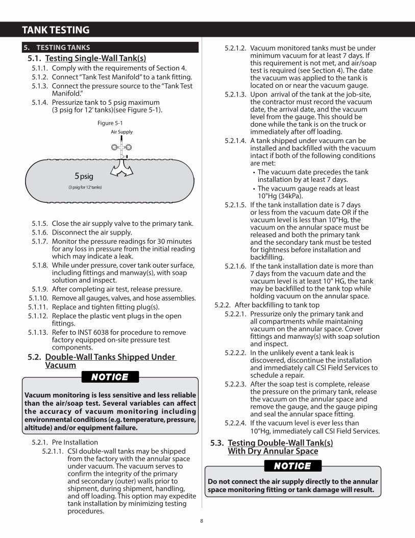
4.3.5.1. Use a contractor supplied “Tank Test Manifold” connected to a tank primary fitting (see Figure 4-1).
4.3.6. Gauges must have a maximum full-scale reading of 15 psig (40 kPa) with ½ psig (3 kPa) or smaller increments.
4.3.7. Pressure-relief device must be sized and set to prevent the tank from being pressurized in excess of the maximum allowed test pressure (6 psig / 41 kPa maximum or 4 psig / 28 kPa for 12’ tanks).
Do not connect air supply directly to the bulkhead monitor fitting or tank damage will result.
Air Supply Valve ClosedAir Supply Valve Open
BackupAir Supply Gauge
Air SupplyGauge
Pressure-ReliefDevice
PrimaryTank Fitting
Figure 4-1
Tank Test Manifold
Do not stand on or approach endcaps, manways, or fittings while pressurizing tanks. Do not lift or hoist tank under pressure. These actions could result in death or serious injury.
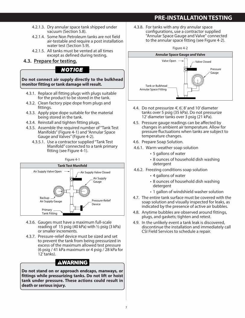
4.3.8. For tanks with any dry annular space configurations, use a contractor supplied"Annular Space Gauge and Valve" connected to the annular space fitting (see Figure 4-2).
4.4. Do not pressurize 4’, 6’, 8’ and 10’ diametertanks over 5 psig (35 kPa). Do not pressurize12’ diameter tanks over 3 psig (21 kPa).
4.5. Pressure gauge readings can be affected by changes in ambient air temperature. Allow for pressure fluctuations when tanks are subject to temperature changes.
4.6. Prepare Soap Solution.4.6.1. Warm weather soap solution
• 5 gallons of water • 8 ounces of household dish washing detergent
4.6.2. Freezing conditions soap solution • 4 gallons of water • 8 ounces of household dish washing detergent
• 1 gallon of windshield washer solution4.7. The entire tank surface must be covered with the
soap solution and visually inspected for leaks, as indicated by the presence of active air bubbles.
4.8. Anytime bubbles are observed around fittings, plugs, and gaskets; tighten and retest.
4.9. In the unlikely event a tank leak is discovered, discontinue the installation and immediately call CSI Field Services to schedule a repair.
PressureGauge
Valve ClosedValve Open
Tank or BulkheadAnnular Space Fitting
Figure 4-2
Annular Space Gauge and Valve
PRE-INSTALLATION TESTING
8
5. TESTING TANKS
5.1. Testing Single-Wall Tank(s)5.1.1. Comply with the requirements of Section 4.5.1.2. Connect “Tank Test Manifold” to a tank fitting.5.1.3. Connect the pressure source to the “Tank Test
Manifold.”5.1.4. Pressurize tank to 5 psig maximum
(3 psig for 12’ tanks)(see Figure 5-1).
5.1.5. Close the air supply valve to the primary tank.5.1.6. Disconnect the air supply.5.1.7. Monitor the pressure readings for 30 minutes
for any loss in pressure from the initial reading which may indicate a leak.
5.1.8. While under pressure, cover tank outer surface, including fittings and manway(s), with soap solution and inspect.
5.1.9. After completing air test, release pressure.5.1.10. Remove all gauges, valves, and hose assemblies.5.1.11. Replace and tighten fitting plug(s).5.1.12. Replace the plastic vent plugs in the open
fittings.5.1.13. Refer to INST 6038 for procedure to remove
factory equipped on-site pressure test components.
5.2. Double-Wall Tanks Shipped Under Vacuum
5.2.1. Pre Installation5.2.1.1. CSI double-wall tanks may be shipped
from the factory with the annular space under vacuum. The vacuum serves to confirm the integrity of the primary and secondary (outer) walls prior to shipment, during shipment, handling, and off loading. This option may expedite tank installation by minimizing testing procedures.
Air Supply
5psig(3 psig for 12’ tanks)
Figure 5-1
Vacuum monitoring is less sensitive and less reliable than the air/soap test. Several variables can affect the accuracy of vacuum monitoring including environmental conditions (e.g. temperature, pressure, altitude) and/or equipment failure.
5.2.1.2. Vacuum monitored tanks must be under minimum vacuum for at least 7 days. If this requirement is not met, and air/soap test is required (see Section 4). The date the vacuum was applied to the tank is located on or near the vacuum gauge.
5.2.1.3. Upon arrival of the tank at the job-site, the contractor must record the vacuum date, the arrival date, and the vacuum level from the gauge. This should be done while the tank is on the truck or immediately after off loading.
5.2.1.4. A tank shipped under vacuum can be installed and backfilled with the vacuum intact if both of the following conditions are met:
• The vacuum date precedes the tank installation by at least 7 days.
• The vacuum gauge reads at least 10"Hg (34kPa).
5.2.1.5. If the tank installation date is 7 days or less from the vacuum date OR if the vacuum level is less than 10"Hg, the vacuum on the annular space must be released and both the primary tank and the secondary tank must be tested for tightness before installation and backfilling.
5.2.1.6. If the tank installation date is more than 7 days from the vacuum date and the vacuum level is at least 10" HG, the tank may be backfilled to the tank top while holding vacuum on the annular space.
5.2.2. After backfilling to tank top5.2.2.1. Pressurize only the primary tank and
all compartments while maintaining vacuum on the annular space. Cover fittings and manway(s) with soap solution and inspect.
5.2.2.2. In the unlikely event a tank leak is discovered, discontinue the installation and immediately call CSI Field Services to schedule a repair.
5.2.2.3. After the soap test is complete, release the pressure on the primary tank, release the vacuum on the annular space and remove the gauge, and the gauge piping and seal the annular space fitting.
5.2.2.4. If the vacuum level is ever less than 10"Hg, immediately call CSI Field Services.
5.3. Testing Double-Wall Tank(s)With Dry Annular Space
Do not connect the air supply directly to the annular space monitoring fitting or tank damage will result.
TANK TESTING
9
5.3.1. Comply with the requirements of Section 4.5.3.2. Connect “Tank Test Manifold” to a primary tank
fitting.5.3.3. Connect hose between a primary tank fitting
and “Annular Space Gauge and Valve.”5.3.4. Close valve between primary tank and annular
space.5.3.5. Connect the pressure source to the “Tank Test
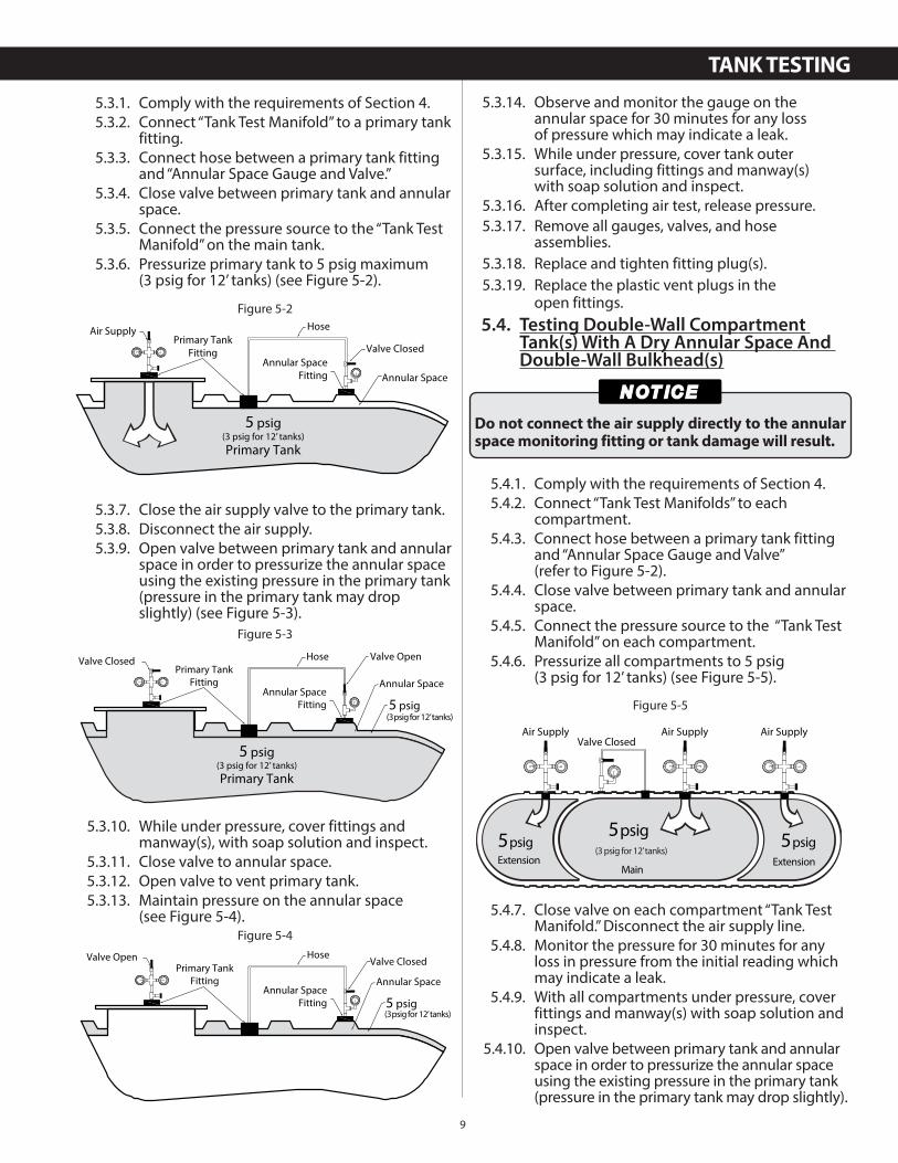
Manifold” on the main tank.5.3.6. Pressurize primary tank to 5 psig maximum
(3 psig for 12’ tanks) (see Figure 5-2).
5.3.7. Close the air supply valve to the primary tank.5.3.8. Disconnect the air supply.5.3.9. Open valve between primary tank and annular
space in order to pressurize the annular space using the existing pressure in the primary tank (pressure in the primary tank may drop slightly) (see Figure 5-3).
5.3.10. While under pressure, cover fittings and manway(s), with soap solution and inspect.
5.3.11. Close valve to annular space.5.3.12. Open valve to vent primary tank.5.3.13. Maintain pressure on the annular space
(see Figure 5-4).
Figure 5-2
Air Supply
Valve Closed
Hose
Annular SpaceFitting
5 psig
Primary Tank
Annular Space
Primary TankFitting
(3 psig for 12’ tanks)
Figure 5-3
Valve Closed Valve OpenHose
Annular SpaceFitting
Annular Space
5 psig
Primary TankFitting
5 psig
Primary Tank(3 psig for 12’ tanks)
(3 psig for 12’ tanks)
Figure 5-4
Valve Open Hose
Annular SpaceFitting
Primary TankFitting
Valve Closed
Annular Space
5 psig(3 psig for 12’ tanks)
5.3.14. Observe and monitor the gauge on the annular space for 30 minutes for any lossof pressure which may indicate a leak.
5.3.15. While under pressure, cover tank outersurface, including fittings and manway(s)with soap solution and inspect.
5.3.16. After completing air test, release pressure.5.3.17. Remove all gauges, valves, and hose
assemblies.5.3.18. Replace and tighten fitting plug(s).5.3.19. Replace the plastic vent plugs in the
open fittings.5.4. Testing Double-Wall Compartment
Tank(s) With A Dry Annular Space And Double-Wall Bulkhead(s)
5.4.1. Comply with the requirements of Section 4.5.4.2. Connect “Tank Test Manifolds” to each
compartment.5.4.3. Connect hose between a primary tank fitting
and “Annular Space Gauge and Valve” (refer to Figure 5-2).
5.4.4. Close valve between primary tank and annular space.
5.4.5. Connect the pressure source to the “Tank Test Manifold” on each compartment.
5.4.6. Pressurize all compartments to 5 psig(3 psig for 12’ tanks) (see Figure 5-5).
5.4.7. Close valve on each compartment “Tank Test Manifold.” Disconnect the air supply line.
5.4.8. Monitor the pressure for 30 minutes for any loss in pressure from the initial reading which may indicate a leak.
5.4.9. With all compartments under pressure, cover fittings and manway(s) with soap solution and inspect.
5.4.10. Open valve between primary tank and annular space in order to pressurize the annular space using the existing pressure in the primary tank (pressure in the primary tank may drop slightly).
Do not connect the air supply directly to the annular space monitoring fitting or tank damage will result.
Air Supply Air SupplyAir SupplyValve Closed
5psigExtension
5psig
Main
(3 psig for 12’ tanks)5psig
Extension
Figure 5-5
TANK TESTING
10
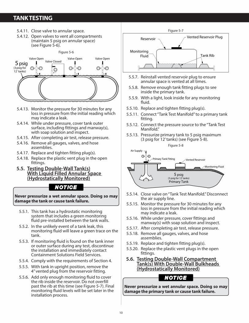
5.4.11. Close valve to annular space.5.4.12. Open valves to vent all compartments
(maintain 5 psig on annular space)(see Figure 5-6).
5.4.13. Monitor the pressure for 30 minutes for any loss in pressure from the initial reading which may indicate a leak.
5.4.14. While under pressure, cover tank outersurface, including fittings and manway(s),with soap solution and inspect.
5.4.15. After completing air test, release pressure.5.4.16. Remove all gauges, valves, and hose
assemblies.5.4.17. Replace and tighten fitting plug(s).5.4.18. Replace the plastic vent plug in the open
fittings.5.5. Testing Double-Wall Tank(s)
With Liquid Filled Annular Space (Hydrostatically Monitored)
5.5.1. This tank has a hydrostatic monitoringsystem that includes a green monitoringfluid pre-installed between the tank walls.
5.5.2. In the unlikely event of a tank leak, this monitoring fluid will leave a green trace on the tank.
5.5.3. If monitoring fluid is found on the tank inner or outer surface during any test, discontinue the installation and immediately contact Containment Solutions Field Services.
5.5.4. Comply with the requirements of Section 4.5.5.5. With tank in upright position, remove the
4” vented plug from the reservoir fitting.5.5.6. Add only enough monitoring fluid to cover
the rib inside the reservoir. Do not overfill past the rib at this time (see Figure 5-7). Final monitoring fluid levels will be set later in the installation process.
Figure 5-6
Valve Open Valve OpenValve Open
(3 psig for12’ tanks)
5 psig Valve Closed
Never pressurize a wet annular space. Doing so may damage the tank or cause tank failure.
5.5.7. Reinstall vented reservoir plug to ensure annular space is vented at all times.
5.5.8. Remove enough tank fitting plugs to see inside the primary tank.
5.5.9. With a light, look inside for any monitoring fluid.
5.5.10. Replace and tighten fitting plug(s).5.5.11. Connect “Tank Test Manifold” to a primary tank
fitting.5.5.12. Connect the pressure source to the “Tank Test
Manifold.”5.5.13. Pressurize primary tank to 5 psig maximum
(3 psig for 12’ tanks) (see Figure 5-8).
5.5.14. Close valve on “Tank Test Manifold.” Disconnect the air supply line.
5.5.15. Monitor the pressure for 30 minutes for any loss in pressure from the initial reading which may indicate a leak.
5.5.16. While under pressure, cover fittings and manway(s) with soap solution and inspect.
5.5.17. After completing air test, release pressure.5.5.18. Remove all gauges, valves, and hose
assemblies.5.5.19. Replace and tighten fitting plug(s).5.5.20. Replace the plastic vent plugs in the open
fittings.5.6. Testing Double-Wall Compartment
Tank(s) With Double-Wall Bulkheads (Hydrostatically Monitored)
Tank RibMonitoring
Fluid
Reservoir Vented Reservoir Plug
Figure 5-7
Air Supply
Monitoring Fluid
Vented ReservoirPrimary Tank Fitting
5 psig
Primary Tank(3 psig for 12’ tanks)
Figure 5-8
Never pressurize a wet annular space. Doing so may damage the primary tank or cause tank failure.
TANK TESTING
11
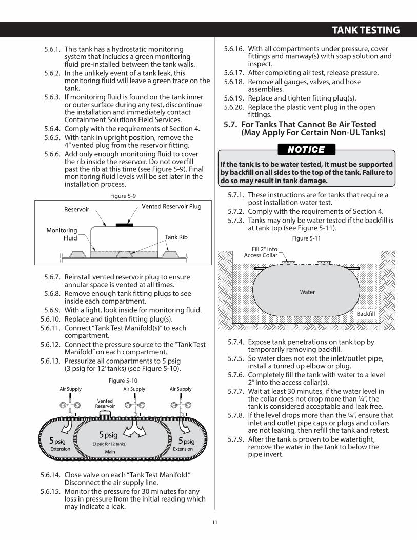
5.6.1. This tank has a hydrostatic monitoringsystem that includes a green monitoringfluid pre-installed between the tank walls.
5.6.2. In the unlikely event of a tank leak, this monitoring fluid will leave a green trace on the tank.
5.6.3. If monitoring fluid is found on the tank inner or outer surface during any test, discontinue the installation and immediately contact Containment Solutions Field Services.
5.6.4. Comply with the requirements of Section 4.5.6.5. With tank in upright position, remove the
4” vented plug from the reservoir fitting.5.6.6. Add only enough monitoring fluid to cover
the rib inside the reservoir. Do not overfill past the rib at this time (see Figure 5-9). Final monitoring fluid levels will be set later in the installation process.
5.6.7. Reinstall vented reservoir plug to ensure annular space is vented at all times.
5.6.8. Remove enough tank fitting plugs to see inside each compartment.
5.6.9. With a light, look inside for monitoring fluid.5.6.10. Replace and tighten fitting plug(s).5.6.11. Connect “Tank Test Manifold(s)” to each
compartment.5.6.12. Connect the pressure source to the “Tank Test
Manifold” on each compartment.5.6.13. Pressurize all compartments to 5 psig
(3 psig for 12’ tanks) (see Figure 5-10).
5.6.14. Close valve on each “Tank Test Manifold.” Disconnect the air supply line.
5.6.15. Monitor the pressure for 30 minutes for any loss in pressure from the initial reading which may indicate a leak.
Tank RibMonitoring
Fluid
Reservoir Vented Reservoir Plug
Figure 5-9
Air Supply Air SupplyAir Supply
VentedReservoir
5psigExtension
5psig
Main
(3 psig for 12’ tanks) 5psigExtension
Figure 5-10
5.6.16. With all compartments under pressure, cover fittings and manway(s) with soap solution and inspect.
5.6.17. After completing air test, release pressure.5.6.18. Remove all gauges, valves, and hose
assemblies.5.6.19. Replace and tighten fitting plug(s).5.6.20. Replace the plastic vent plug in the open
fittings.5.7. For Tanks That Cannot Be Air Tested
(May Apply For Certain Non-UL Tanks)
5.7.1. These instructions are for tanks that require a post installation water test.
5.7.2. Comply with the requirements of Section 4.5.7.3. Tanks may only be water tested if the backfill is
at tank top (see Figure 5-11).
5.7.4. Expose tank penetrations on tank top by temporarily removing backfill.
5.7.5. So water does not exit the inlet/outlet pipe, install a turned up elbow or plug.
5.7.6. Completely fill the tank with water to a level2” into the access collar(s).
5.7.7. Wait at least 30 minutes, if the water level in the collar does not drop more than ¼”, the tank is considered acceptable and leak free.
5.7.8. If the level drops more than the ¼”, ensure that inlet and outlet pipe caps or plugs and collars are not leaking, then refill the tank and retest.
5.7.9. After the tank is proven to be watertight, remove the water in the tank to below the pipe invert.
If the tank is to be water tested, it must be supported by backfill on all sides to the top of the tank. Failure to do so may result in tank damage.
Water
Fill 2" intoAccess Collar
Backfill
Figure 5-11
TANK TESTING
12
6. EXCAVATION & TANK CLEARANCE
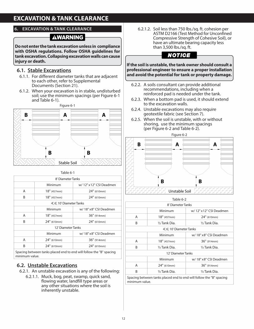
6.1. Stable Excavations6.1.1. For different diameter tanks that are adjacent
to each other, refer to Supplemental Documents (Section 21).
6.1.2. When your excavation is in stable, undisturbed soil; use the minimum spacings (per Figure 6-1 and Table 6-1).
6.2. Unstable Excavations6.2.1. An unstable excavation is any of the following:
6.2.1.1. Muck, bog, peat, swamp, quick sand, flowing water, landfill type areas or any other situations where the soil is inherently unstable.
Do not enter the tank excavation unless in compliance with OSHA regulations. Follow OSHA guidelines for tank excavation. Collapsing excavation walls can cause injury or death.
Figure 6-1
B A A
BB
Stable Soil
8' Diameter Tanks
Minimum w/ 12" x 12" CSI Deadmen
A 18" (457mm) 24" (610mm)
B 18" (457mm) 24" (610mm)
4', 6', 10' Diameter Tanks
Minimum w/ 18" x 8" CSI Deadmen
A 18" (457mm) 36" (914mm)
B 24" (610mm) 24" (610mm)
12' Diameter Tanks
Minimum w/ 18" x 8" CSI Deadmen
A 24" (610mm) 36" (914mm)
B 24" (610mm) 24" (610mm)
Spacing between tanks placed end to end will follow the "B" spacing minimum value.
Table 6-1
6.2.1.2. Soil less than 750 lbs./sq. ft. cohesion per ASTM D2166 (Test Method for Unconfined Compressive Strength of Cohesive Soil), or have an ultimate bearing capacity less than 3,500 lbs./sq. ft.
6.2.2. A soils consultant can provide additional recommendations, including when a reinforced pad is needed under the tank.
6.2.3. When a bottom pad is used, it should extend to the excavation walls.
6.2.4. Unstable excavations may also require geotextile fabric (see Section 7).
6.2.5. When the soil is unstable, with or without shoring, use the minimum spacings(per Figure 6-2 and Table 6-2).
If the soil is unstable, the tank owner should consult a professional engineer to ensure a proper installation and avoid the potential for tank or property damage.
Figure 6-2
B A A
BB
Unstable Soil
8' Diameter Tanks
Minimum w/ 12" x 12" CSI Deadmen
A 18" (457mm) 24" (610mm)
B ½ Tank Dia. ½ Tank Dia.
4', 6', 10' Diameter Tanks
Minimum w/ 18" x 8" CSI Deadmen
A 18" (457mm) 36" (914mm)
B ½ Tank Dia. ½ Tank Dia.
12' Diameter Tanks
Minimum w/ 18" x 8" CSI Deadmen
A 24" (610mm) 36" (914mm)
B ½ Tank Dia. ½ Tank Dia.
Spacing between tanks placed end to end will follow the "B" spacing minimum value.
Table 6-2
EXCAVATION & TANK CLEARANCE
13
6.3. Shoring Removal
6.3.1. After the backfill is properly placed completely around the tank(s):
6.3.1.1. Vibrate shoring and pull slowly to top of backfill.
6.3.1.2. Fill any voids created by the pulled shoring with approved backfill.
6.3.2. All shoring should be removed and all voids must be filled using a long handled probe before continuing installation.
6.3.3. If side shoring is left in place, the shoring must not degrade over the life of the installation.
6.3.4. Shoring system components cannot be placed under the tank.
6.4. Tank Location - Nearby Structures6.4.1. CSI recommends that the tank owner seek
the advice of a local foundation professional engineer to determine the proper placement of a tank excavation near any slabs or foundations.
6.4.2. The location of a tank can be affected by the location of nearby structures. When selecting a tank site, care must be taken to avoid undermining the foundations of new or existing structures.
6.4.3. Ensure that downward forces from loads carried by the foundations and supports of nearby structures (constructed before or after tank installation) are not transmitted to the tanks. (Refer to NFPA 30 for additional details).
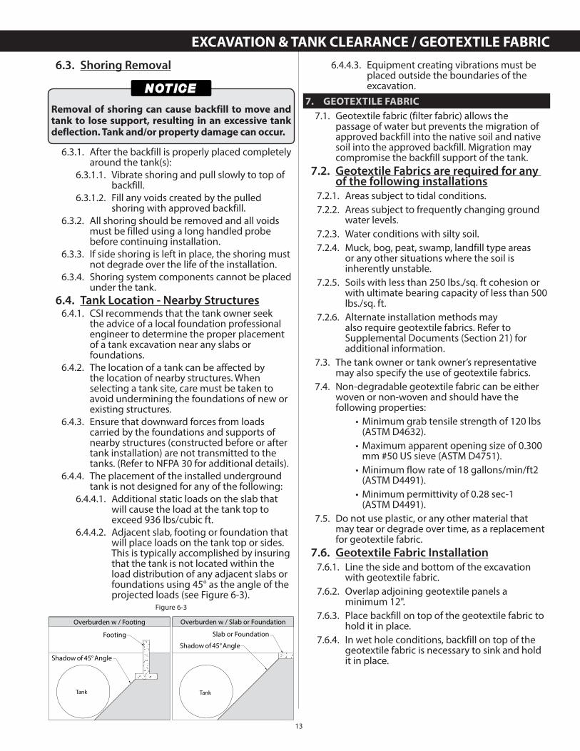
6.4.4. The placement of the installed underground tank is not designed for any of the following:
6.4.4.1. Additional static loads on the slab that will cause the load at the tank top to exceed 936 lbs/cubic ft.
6.4.4.2. Adjacent slab, footing or foundation that will place loads on the tank top or sides. This is typically accomplished by insuring that the tank is not located within the load distribution of any adjacent slabs or foundations using 45° as the angle of the projected loads (see Figure 6-3).
Removal of shoring can cause backfill to move and tank to lose support, resulting in an excessive tank deflection. Tank and/or property damage can occur.
Figure 6-3
Footing
Shadow of 45° Angle
Shadow of 45° Angle
Slab or Foundation
Overburden w / Footing Overburden w / Slab or Foundation
TankTank
6.4.4.3. Equipment creating vibrations must be placed outside the boundaries of the excavation.
7. GEOTEXTILE FABRIC
7.1. Geotextile fabric (filter fabric) allows the passage of water but prevents the migration of approved backfill into the native soil and native soil into the approved backfill. Migration may compromise the backfill support of the tank.
7.2. Geotextile Fabrics are required for any of the following installations
7.2.1. Areas subject to tidal conditions.7.2.2. Areas subject to frequently changing ground
water levels.7.2.3. Water conditions with silty soil.7.2.4. Muck, bog, peat, swamp, landfill type areas
or any other situations where the soil is inherently unstable.
7.2.5. Soils with less than 250 lbs./sq. ft cohesion or with ultimate bearing capacity of less than 500 lbs./sq. ft.
7.2.6. Alternate installation methods may also require geotextile fabrics. Refer to Supplemental Documents (Section 21) for additional information.
7.3. The tank owner or tank owner’s representative may also specify the use of geotextile fabrics.
7.4. Non-degradable geotextile fabric can be either woven or non-woven and should have the following properties:
• Minimum grab tensile strength of 120 lbs (ASTM D4632).
• Maximum apparent opening size of 0.300 mm #50 US sieve (ASTM D4751).
• Minimum fl ow rate of 18 gallons/min/ft2 (ASTM D4491).
• Minimum permittivity of 0.28 sec-1(ASTM D4491).
7.5. Do not use plastic, or any other material that may tear or degrade over time, as a replacement for geotextile fabric.
7.6. Geotextile Fabric Installation7.6.1. Line the side and bottom of the excavation
with geotextile fabric.7.6.2. Overlap adjoining geotextile panels a
minimum 12".7.6.3. Place backfill on top of the geotextile fabric to
hold it in place.7.6.4. In wet hole conditions, backfill on top of the
geotextile fabric is necessary to sink and hold it in place.
EXCAVATION & TANK CLEARANCE / GEOTEXTILE FABRIC
14
8. BURIAL DEPTH & COVER
8.1. Adhere to the minimum and maximum dimensions in this section.
8.2. In wet conditions, sufficient overburden and/or an appropriate anchoring system must be used to offset buoyancy of the tank. Minimum burial depth (section 8) may not be sufficient to anchor the tank in buoyant conditions. Refer to the “Anchor Chart” (Appendix A) for minimum burial depth in buoyant conditions.
8.2.1. Traffic pad must extend at least 12” beyond tank perimeter in all directions.
8.2.2. The maximum burial depth is 7’ from the tank top to grade elevation. Tanks can be designed for burial depths greater than 7’. Contact your local CSI representative prior to tank purchase.
8.2.3. Dry hole excavations must have a minimum of 12” and a maximum of 24” backfill between the bottom of the tank and either the bottom of the excavation or the top of the concrete anchor pad.
8.2.4. Wet hole excavations must have a minimum of 18” and a maximum of 24” backfill between the bottom of the tank and either the bottom of the excavation or the top of the concrete anchor pad.
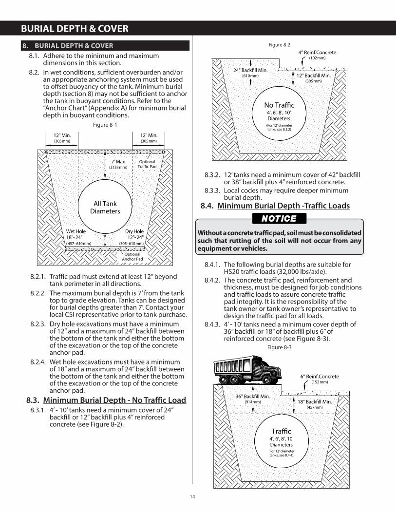
8.3. Minimum Burial Depth - No Traffic Load8.3.1. 4’ - 10’ tanks need a minimum cover of 24”
backfill or 12” backfill plus 4” reinforced concrete (see Figure 8-2).
Figure 8-1
All TankDiameters
OptionalAnchor Pad
OptionalTraffic Pad
7' Max(2133mm)
Dry Hole12"- 24"
(305-610mm)
Wet Hole18"- 24"(457-610mm)
12" Min.(305mm)
12" Min.(305mm)
8.3.2. 12’ tanks need a minimum cover of 42” backfill or 38” backfill plus 4” reinforced concrete.
8.3.3. Local codes may require deeper minimum burial depth.
8.4. Minimum Burial Depth -Traffic Loads
8.4.1. The following burial depths are suitable for HS20 traffic loads (32,000 lbs/axle).
8.4.2. The concrete traffic pad, reinforcement and thickness, must be designed for job conditions and traffic loads to assure concrete traffic pad integrity. It is the responsibility of the tank owner or tank owner’s representative to design the traffic pad for all loads.
8.4.3. 4’ - 10’ tanks need a minimum cover depth of 36” backfill or 18” of backfill plus 6” of reinforced concrete (see Figure 8-3).
Figure 8-2
No Traffic
24" Backfill Min.(610mm) 12" Backfill Min.
(305mm)
4" Reinf.Concrete(102mm)
4', 6', 8', 10'Diameters
(For 12’ diametertanks, see 8.3.2)
Without a concrete traffic pad, soil must be consolidated such that rutting of the soil will not occur from any equipment or vehicles.
Figure 8-3
6" Reinf.Concrete(152mm)
Traffic
36" Backfill Min.(914mm) 18" Backfill Min.
(457mm)
4', 6', 8', 10'Diameters
(For 12’ diametertanks, see 8.4.4)
BURIAL DEPTH & COVER
15
8.4.4. 12’ tanks need a minimum cover of 48” backfill or 36” backfill plus 6” reinforced concrete.
9. ANCHORING
9.1. It is the responsibility of the tank owner or tank owner’s representative to determine the appropriate anchoring method and to design the anchoring system.
9.2. CSI has provided an “Anchor Chart” at the end of this instruction booklet (Appendix A) that covers the minimum burial depths for the three common methods of anchoring tanks.
9.3. The three common methods are: • Deadmen Anchors • Concrete Anchor Pad • Overburden (no mechanical anchoring)
9.4. CSI offers an engineered mechanical anchoring system designed for each size tank consisting of deadman anchors, straps, and hardware.
9.5. Burial depth, straps, turnbuckles, shackles, wire rope, deadmen and anchor pads can be combined to provide anchoring using the information provided in this section.
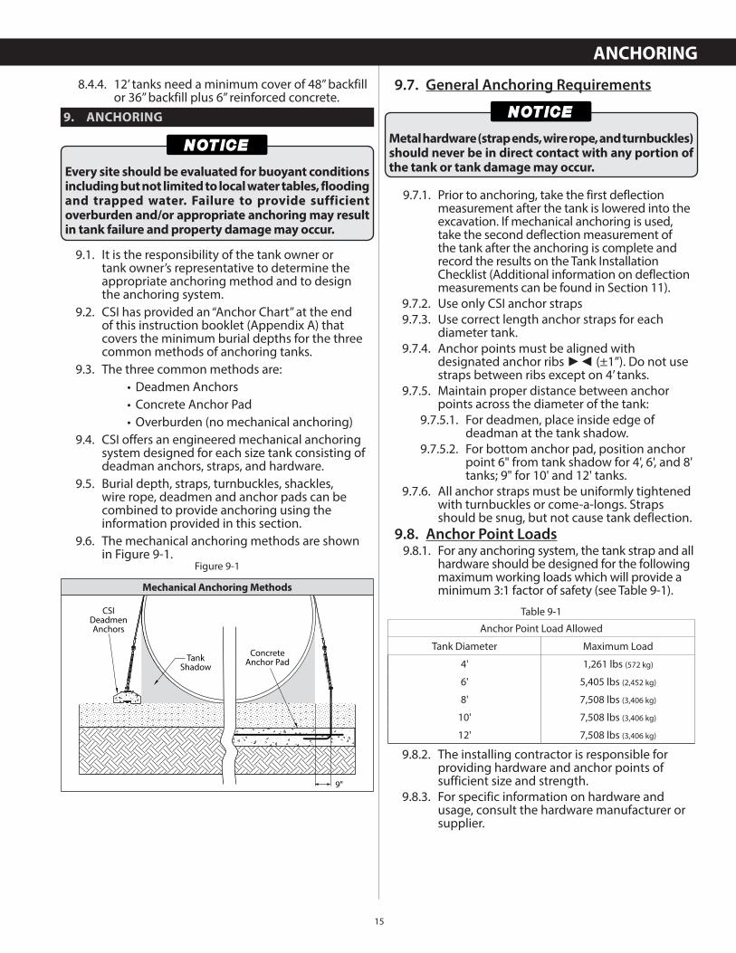
9.6. The mechanical anchoring methods are shown in Figure 9-1.
Every site should be evaluated for buoyant conditions including but not limited to local water tables, flooding and trapped water. Failure to provide sufficient overburden and/or appropriate anchoring may result in tank failure and property damage may occur.
TankShadow
CSIDeadmenAnchors
ConcreteAnchor Pad
9"
Figure 9-1
Mechanical Anchoring Methods
9.7. General Anchoring Requirements
9.7.1. Prior to anchoring, take the first deflection measurement after the tank is lowered into the excavation. If mechanical anchoring is used, take the second deflection measurement of the tank after the anchoring is complete and record the results on the Tank Installation Checklist (Additional information on deflection measurements can be found in Section 11).
9.7.2. Use only CSI anchor straps9.7.3. Use correct length anchor straps for each
diameter tank.9.7.4. Anchor points must be aligned with
designated anchor ribs ►◄ (±1”). Do not use straps between ribs except on 4’ tanks.
9.7.5. Maintain proper distance between anchor points across the diameter of the tank:
9.7.5.1. For deadmen, place inside edge of deadman at the tank shadow.
9.7.5.2. For bottom anchor pad, position anchor point 6" from tank shadow for 4', 6', and 8' tanks; 9" for 10' and 12' tanks.
9.7.6. All anchor straps must be uniformly tightened with turnbuckles or come-a-longs. Straps should be snug, but not cause tank deflection.
9.8. Anchor Point Loads9.8.1. For any anchoring system, the tank strap and all
hardware should be designed for the following maximum working loads which will provide a minimum 3:1 factor of safety (see Table 9-1).
9.8.2. The installing contractor is responsible for providing hardware and anchor points of sufficient size and strength.
9.8.3. For specific information on hardware and usage, consult the hardware manufacturer or supplier.
Metal hardware (strap ends, wire rope, and turnbuckles) should never be in direct contact with any portion of the tank or tank damage may occur.
Anchor Point Load Allowed
Tank Diameter Maximum Load
4' 1,261 lbs (572 kg)
6' 5,405 lbs (2,452 kg)
8' 7,508 lbs (3,406 kg)
10' 7,508 lbs (3,406 kg)
12' 7,508 lbs (3,406 kg)
Table 9-1
ANCHORING
16
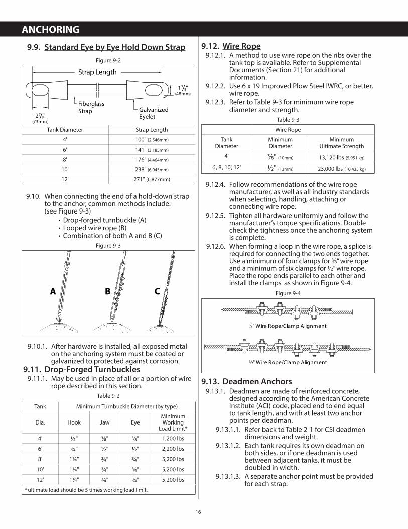
9.9. Standard Eye by Eye Hold Down Strap
9.10. When connecting the end of a hold-down strap to the anchor, common methods include:(see Figure 9-3)
• Drop-forged turnbuckle (A) • Looped wire rope (B) • Combination of both A and B (C)
9.10.1. After hardware is installed, all exposed metal on the anchoring system must be coated or galvanized to protected against corrosion.
9.11. Drop-Forged Turnbuckles9.11.1. May be used in place of all or a portion of wire
rope described in this section.
Tank Diameter Strap Length
4' 100" (2,546mm)
6' 141" (3,185mm)
8' 176" (4,464mm)
10' 238" (6,045mm)
12' 271" (6,877mm)
Figure 9-2
Strap Length
17/8"(48mm)
27/8"(73mm)
FiberglassStrap Galvanized
Eyelet
Figure 9-3
A B C
Tank Minimum Turnbuckle Diameter (by type)
Dia. Hook Jaw EyeMinimumWorking
Load Limit*
4' ½" 3⁄8" 3⁄8" 1,200 lbs
6' ¾" ½" ½" 2,200 lbs
8' 1¼" ¾" ¾" 5,200 lbs
10' 1¼" ¾" ¾" 5,200 lbs
12' 1¼" ¾" ¾" 5,200 lbs
* ultimate load should be 5 times working load limit.
Table 9-2
9.12. Wire Rope9.12.1. A method to use wire rope on the ribs over the
tank top is available. Refer to Supplemental Documents (Section 21) for additional information.
9.12.2. Use 6 x 19 Improved Plow Steel IWRC, or better, wire rope.
9.12.3. Refer to Table 9-3 for minimum wire rope diameter and strength.
9.12.4. Follow recommendations of the wire rope manufacturer, as well as all industry standards when selecting, handling, attaching or connecting wire rope.
9.12.5. Tighten all hardware uniformly and follow the manufacturer’s torque specifications. Double check the tightness once the anchoring system is complete.
9.12.6. When forming a loop in the wire rope, a splice is required for connecting the two ends together. Use a minimum of four clamps for 3⁄8” wire rope and a minimum of six clamps for ½” wire rope. Place the rope ends parallel to each other and install the clamps as shown in Figure 9-4.
9.13. Deadmen Anchors9.13.1. Deadmen are made of reinforced concrete,
designed according to the American Concrete Institute (ACI) code, placed end to end equal to tank length, and with at least two anchor points per deadman.
9.13.1.1. Refer back to Table 2-1 for CSI deadmen dimensions and weight.
9.13.1.2. Each tank requires its own deadman on both sides, or if one deadman is used between adjacent tanks, it must be doubled in width.
9.13.1.3. A separate anchor point must be provided for each strap.
Table 9-3
Wire Rope
TankDiameter
MinimumDiameter
MinimumUltimate Strength
4' 3⁄8" (10mm) 13,120 lbs (5,951 kg)
6', 8', 10', 12' ½" (13mm) 23,000 lbs (10,433 kg)
Figure 9-4
3 8" Wire Rope/Clamp Alignment
½" Wire Rope/Clamp Alignment
ANCHORING
17
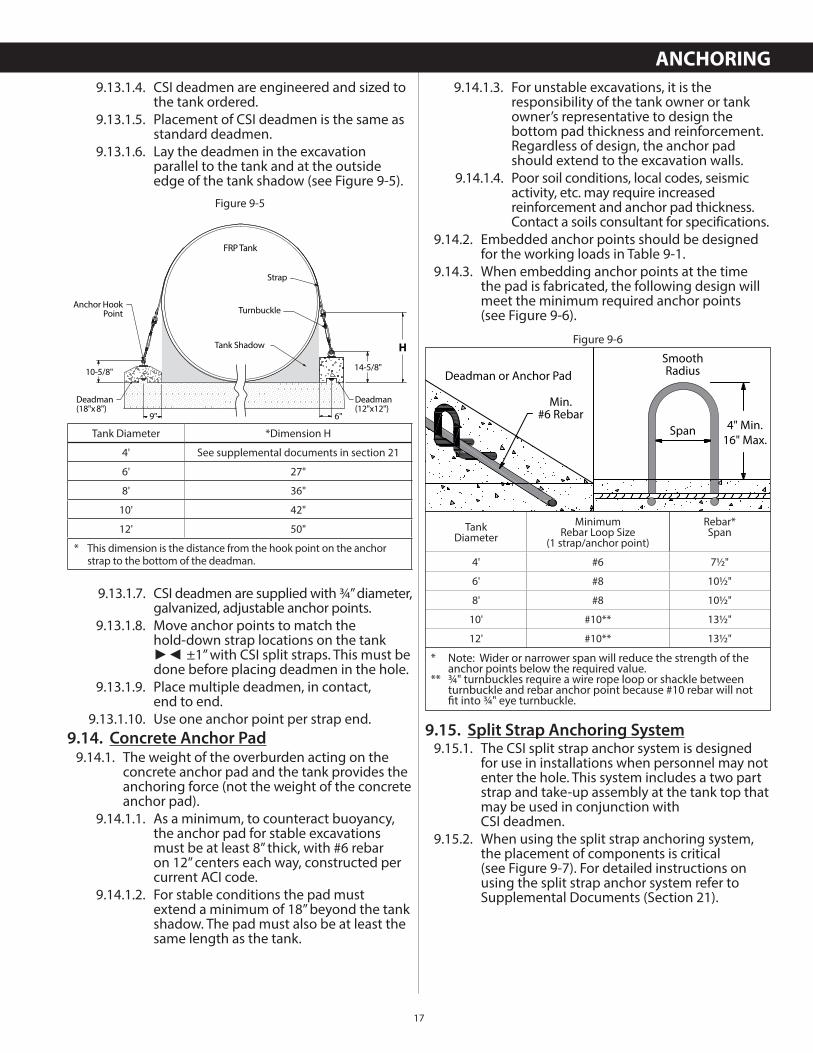
9.13.1.4. CSI deadmen are engineered and sized to the tank ordered.
9.13.1.5. Placement of CSI deadmen is the same as standard deadmen.
9.13.1.6. Lay the deadmen in the excavation parallel to the tank and at the outside edge of the tank shadow (see Figure 9-5).
9.13.1.7. CSI deadmen are supplied with ¾” diameter, galvanized, adjustable anchor points.
9.13.1.8. Move anchor points to match thehold-down strap locations on the tank ►◄ ±1” with CSI split straps. This must be done before placing deadmen in the hole.
9.13.1.9. Place multiple deadmen, in contact,end to end.
9.13.1.10. Use one anchor point per strap end.9.14. Concrete Anchor Pad
9.14.1. The weight of the overburden acting on the concrete anchor pad and the tank provides the anchoring force (not the weight of the concrete anchor pad).
9.14.1.1. As a minimum, to counteract buoyancy, the anchor pad for stable excavations must be at least 8” thick, with #6 rebar on 12” centers each way, constructed per current ACI code.
9.14.1.2. For stable conditions the pad must extend a minimum of 18” beyond the tank shadow. The pad must also be at least the same length as the tank.
Figure 9-5
Turnbuckle
FRP Tank
Strap
Tank Shadow
Deadman(12"x12")
Deadman(18"x 8")
14-5/8"10-5/8"
9" 6"
H
Anchor HookPoint
Tank Diameter *Dimension H
4' See supplemental documents in section 21
6' 27"
8' 36"
10' 42"
12' 50"
* This dimension is the distance from the hook point on the anchor strap to the bottom of the deadman.
9.14.1.3. For unstable excavations, it is the responsibility of the tank owner or tank owner’s representative to design the bottom pad thickness and reinforcement. Regardless of design, the anchor pad should extend to the excavation walls.
9.14.1.4. Poor soil conditions, local codes, seismic activity, etc. may require increased reinforcement and anchor pad thickness. Contact a soils consultant for specifications.
9.14.2. Embedded anchor points should be designed for the working loads in Table 9-1.
9.14.3. When embedding anchor points at the time the pad is fabricated, the following design will meet the minimum required anchor points(see Figure 9-6).
9.15. Split Strap Anchoring System9.15.1. The CSI split strap anchor system is designed
for use in installations when personnel may not enter the hole. This system includes a two part strap and take-up assembly at the tank top that may be used in conjunction withCSI deadmen.
9.15.2. When using the split strap anchoring system, the placement of components is critical (see Figure 9-7). For detailed instructions on using the split strap anchor system refer to Supplemental Documents (Section 21).
Figure 9-6
Span 4" Min.16" Max.
SmoothRadiusDeadman or Anchor Pad
Min.#6 Rebar
TankDiameter
MinimumRebar Loop Size
(1 strap/anchor point)
Rebar*Span
4' #6 7½"
6' #8 10½"
8' #8 10½"
10' #10** 13½"
12' #10** 13½"
* Note: Wider or narrower span will reduce the strength of the anchor points below the required value.** ¾" turnbuckles require a wire rope loop or shackle between turnbuckle and rebar anchor point because #10 rebar will not fi t into ¾" eye turnbuckle.
ANCHORING
18
10. BALLASTING TANKS (ADDING LIQUID)
10.1. A tank is not adequately protected against flotation until the tank is backfilled to subgrade and the top slab is in place.
10.2. For a tank that is not fully installed, water can enter the hole and the tank will float unless it has been ballasted with fluid to offset buoyancy.
10.3. Use water or fluid heavier than water as ballast. Be sure the ballast will not contaminate the product being stored or clean the tank before product is added. This is especially important for potable water, chemical and diesel exhaust fluid (DEF) tanks.
10.4. Do not make a direct (hard) connection of the ballast fill line to any tank fitting.
10.5. Adding ballast:
10.5.1. At the moment the tank is full, the pressure in the fill line will result in an instant pressurization of the tank which will damage the tank.
10.5.2. This problem can be avoided by providing adequate tank venting or removing the fill line and manually bringing the tank to full capacity.
10.6. Dry Hole - add ballast only after backfill is placed at least 75% of the tank diameter.
Figure 9-7Take-UpAssembly
Strap
CSIDeadmen
Strap
Do not have the annular space connected to the primary space during ballasting or tank damage will occur.
When adding ballast, precautions must be taken so that the tank cannot completely fill. Keep tank vented to prevent pressurization of the tank when adding ballast. As the tank nears full, reduce the fill rate to prevent sudden pressurization or tank damage will occur.
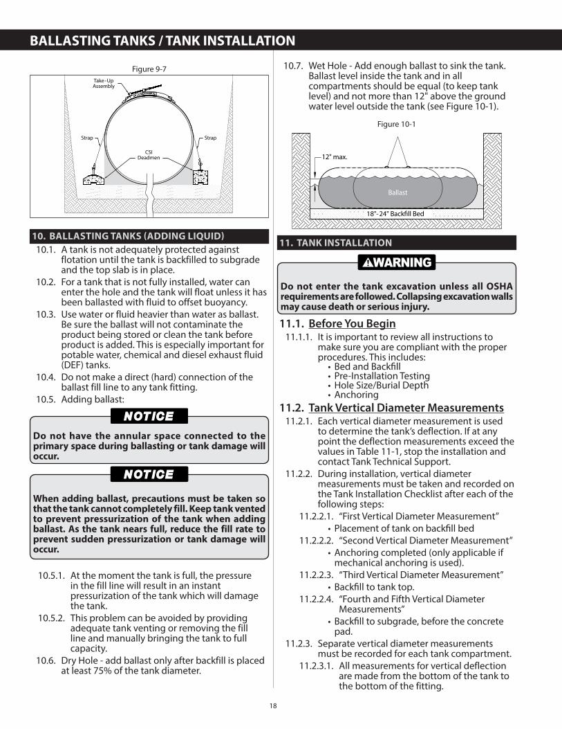
10.7. Wet Hole - Add enough ballast to sink the tank. Ballast level inside the tank and in all compartments should be equal (to keep tank level) and not more than 12" above the ground water level outside the tank (see Figure 10-1).
11. TANK INSTALLATION
11.1. Before You Begin11.1.1. It is important to review all instructions to
make sure you are compliant with the proper procedures. This includes:
• Bed and Backfi ll • Pre-Installation Testing • Hole Size/Burial Depth • Anchoring
11.2. Tank Vertical Diameter Measurements11.2.1. Each vertical diameter measurement is used
to determine the tank’s deflection. If at any point the deflection measurements exceed the values in Table 11-1, stop the installation and contact Tank Technical Support.
11.2.2. During installation, vertical diameter measurements must be taken and recorded on the Tank Installation Checklist after each of the following steps:
11.2.2.1. “First Vertical Diameter Measurement” • Placement of tank on backfi ll bed
11.2.2.2. “Second Vertical Diameter Measurement” • Anchoring completed (only applicable if mechanical anchoring is used).
11.2.2.3. “Third Vertical Diameter Measurement” • Backfi ll to tank top.
11.2.2.4. “Fourth and Fifth Vertical Diameter Measurements”
• Backfi ll to subgrade, before the concrete pad.
11.2.3. Separate vertical diameter measurements must be recorded for each tank compartment.
11.2.3.1. All measurements for vertical deflection are made from the bottom of the tank to the bottom of the fitting.
Figure 10-1
18"-24" Backfill Bed
Ballast
12" max.
Do not enter the tank excavation unless all OSHA requirements are followed. Collapsing excavation walls may cause death or serious injury.
BALLASTING TANKS / TANK INSTALLATION
19
11.2.3.2. All measurements should be made in inches or millimeters using a standard nonmetallic gauge stick.
11.2.3.3. All measurements should be made through the fitting closest to center of tank or each compartment.
11.2.4. Refer to Table 11-1 for maximum deflection values.
11.3. Installation Procedure
11.3.1. Determine if geotextile fabric is required for your installation (see Section 7 for details).
11.3.2. All tank holes must have a minimum of 12” (18” for wet holes) and a maximum of 24” of approved backfill between the bottom of the tank and the bottom of the excavation or concrete anchor pad.
11.3.3. Place tank in excavation with lifting cables attached to lift lugs provided on tank, while maintaining control of tank with guide ropes.
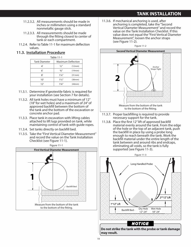
11.3.4. Set tanks directly on backfill bed.11.3.5. Take the “First Vertical Diameter Measurement”
and record the value on the Tank Installation Checklist (see Figure 11-1).
Tank Diameter Maximum Deflection
4' ½" (12mm)
6' ¾" (19mm)
8' 1¼" (31mm)
10' 1½" (38mm)
12' 1¾" (44mm)
Table 11-1
1Backfill Bed
Figure 11-1
First Vertical Diameter Measurement
Measure from the bottom of the tankto the bottom of the fi tting.
11.3.6. If mechanical anchoring is used, after anchoring is completed, take the “Second Vertical Diameter Measurement” and record the value on the Tank Installation Checklist. If this value does not equal the “First Vertical Diameter Measurement”, loosen the anchor straps(see Figure 11-2).
11.3.7. Proper backfilling is required to provide necessary support for the tank.
11.3.8. Place the first 12” lift of approved backfill material evenly around the tank. From the edge of the hole or the top of an adjacent tank, push the backfill in place by using a probe long enough to reach beneath the tank. Work the backfill material under the entire length of the tank between and around ribs and endcaps, eliminating all voids, so the tank is fully supported (see Figure 11-3).
2
AnchorStraps Tight
Figure 11-2
Second Vertical Diameter Measurement
Measure from the bottom of the tankto the bottom of the fi tting.
Figure 11-3
Long Handled Probe
1st 12" Lift1st 12" Lift
2nd 12" Lift2nd 12" Lift
Backfill Bed - Dry Hole12"-24"
Wet Hole18"-24"
Do not strike the tank with the probe or tank damage may result.
TANK INSTALLATION
20
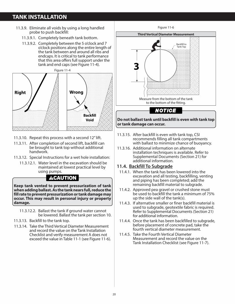
11.3.9. Eliminate all voids by using a long handled probe to push backfill:
11.3.9.1. Completely beneath tank bottom.11.3.9.2. Completely between the 5 o’clock and 7
o’clock positions along the entire length of the tank between and around all ribs and endcaps. It is critical to tank performance that this area offers full support under the tank and end caps (see Figure 11-4).
11.3.10. Repeat this process with a second 12” lift.11.3.11. After completion of second lift, backfill can
be brought to tank top without additional handwork.
11.3.12. Special Instructions for a wet hole installation:11.3.12.1. Water level in the excavation should be
maintained at lowest practical level by using pumps.
11.3.12.2. Ballast the tank if ground water cannot be lowered. Ballast the tank per section 10.
11.3.13. Backfill to the tank top.11.3.14. Take the Third Vertical Diameter Measurement
and record the value on the Tank Installation Checklist and verify measurement A does not exceed the value in Table 11-1 (see Figure 11-6).
Figure 11-4
Right Wrong
Backfill
Void
Keep tank vented to prevent pressurization of tank when adding ballast. As the tank nears full, reduce the fill rate to prevent pressurization or tank damage may occur. This may result in personal injury or property damage.
11.3.15. After backfill is even with tank top, CSI recommends filling all tank compartments with ballast to minimize chance of buoyancy.
11.3.16. Additional information on alternate installation techniques is available. Refer to Supplemental Documents (Section 21) for additional information.
11.4. Backfill To Subgrade11.4.1. When the tank has been lowered into the
excavation and all testing, backfilling, venting and piping has been completed; add the remaining backfill material to subgrade.
11.4.2. Approved pea gravel or crushed stone must be used to backfill the tank a minimum of 75% up the side wall of the tank(s).
11.4.3. If alternative smaller or finer backfill material is used to subgrade, geotextile fabric is required. Refer to Supplemental Documents (Section 21) for additional information.
11.4.4. Once the tank has been backfilled to subgrade, before placement of concrete pad, take the fourth vertical diameter measurement.
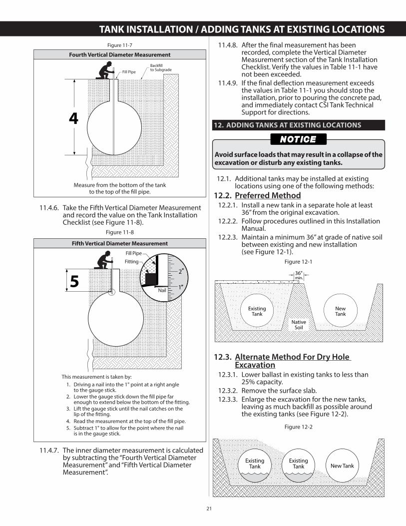
11.4.5. Take the Fourth Vertical Diameter Measurement and record the value on the Tank Installation Checklist (see Figure 11-7).
3
Backfill toTank Top
Figure 11-6
Third Vertical Diameter Measurement
Measure from the bottom of the tankto the bottom of the fi tting.
Do not ballast tank until backfill is even with tank top or tank damage can occur.
TANK INSTALLATION
21
11.4.6. Take the Fifth Vertical Diameter Measurement and record the value on the Tank Installation Checklist (see Figure 11-8).
11.4.7. The inner diameter measurement is calculated by subtracting the “Fourth Vertical Diameter Measurement” and “Fifth Vertical Diameter Measurement”.
4
Backfillto SubgradeFill Pipe
Figure 11-7
Fourth Vertical Diameter Measurement
Measure from the bottom of the tankto the top of the fi ll pipe.
5
Fitting
Fill Pipe
Nail
2″
1″
This measurement is taken by:1. Driving a nail into the 1" point at a right angle
to the gauge stick. 2. Lower the gauge stick down the fill pipe far
enough to extend below the bottom of the fitting. 3. Lift the gauge stick until the nail catches on the
lip of the fitting. 4. Read the measurement at the top of the fill pipe. 5. Subtract 1" to allow for the point where the nail
is in the gauge stick.
Figure 11-8
Fifth Vertical Diameter Measurement
11.4.8. After the final measurement has been recorded, complete the Vertical Diameter Measurement section of the Tank Installation Checklist. Verify the values in Table 11-1 have not been exceeded.
11.4.9. If the final deflection measurement exceeds the values in Table 11-1 you should stop the installation, prior to pouring the concrete pad, and immediately contact CSI Tank Technical Support for directions.
12. ADDING TANKS AT EXISTING LOCATIONS
12.1. Additional tanks may be installed at existing locations using one of the following methods:
12.2. Preferred Method12.2.1. Install a new tank in a separate hole at least
36” from the original excavation.12.2.2. Follow procedures outlined in this Installation
Manual.12.2.3. Maintain a minimum 36” at grade of native soil
between existing and new installation(see Figure 12-1).
12.3. Alternate Method For Dry Hole Excavation
12.3.1. Lower ballast in existing tanks to less than25% capacity.
12.3.2. Remove the surface slab.12.3.3. Enlarge the excavation for the new tanks,
leaving as much backfill as possible around the existing tanks (see Figure 12-2).
Avoid surface loads that may result in a collapse of the excavation or disturb any existing tanks.
ExistingTank
NewTank
NativeSoil
36"min.
Figure 12-1
Figure 12-2
ExistingTank
ExistingTank New Tank
TANK INSTALLATION / ADDING TANKS AT EXISTING LOCATIONS
22
12.3.4. Install shoring, if necessary, to make sure that existing tanks do not move and sufficient backfill remains.
12.3.5. Install all tanks following the instructions outlined in this manual.
12.3.6. Follow and complete the Tank Installation Checklist for all new and existing tanks.
13. PIPING & BOTTOM SUMP CLEARANCES
13.1. Tanks with Bottom Sumps / Fittings13.1.1. To install a tank with a bottom sump or fitting,
the excavation and backfill must be modified as follows. Refer to Supplement Documents (Section 21) for additional information:
13.2. External Piping13.2.1. Isolate the piping from the concrete pad
(see Figure 13-1).
13.2.2. A flexible connector must be directly installed on all tangentially mounted fittings, nozzle or pipe. The flexible connector must allow for ½” of offset, angular, expansion, and compression movement. Refer to Supplemental Documents (Section 21) for additional information.
13.2.3. Nozzle bolt torque can be found in Flexible Connector supplemental document. Refer to Supplemental Documents (Section 21) for additional information.
13.2.4. Take precaution during construction to make sure no damage occurs to the exposed pipe(s).
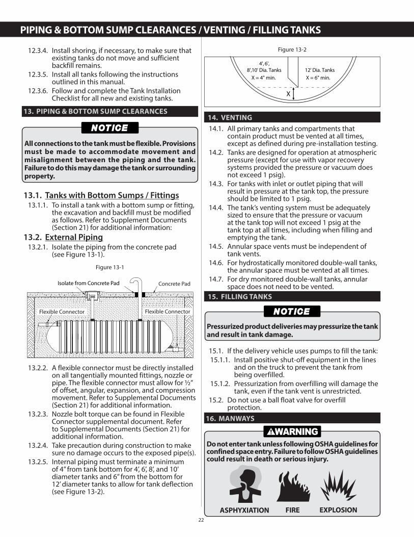
13.2.5. Internal piping must terminate a minimum of 4” from tank bottom for 4’, 6’, 8’, and 10’ diameter tanks and 6” from the bottom for12’ diameter tanks to allow for tank deflection (see Figure 13-2).
All connections to the tank must be flexible. Provisions must be made to accommodate movement and misalignment between the piping and the tank. Failure to do this may damage the tank or surrounding property.
Figure 13-1
Isolate from Concrete Pad Concrete Pad
Flexible Connector Flexible Connector
14. VENTING
14.1. All primary tanks and compartments that contain product must be vented at all times, except as defined during pre-installation testing.
14.2. Tanks are designed for operation at atmospheric pressure (except for use with vapor recovery systems provided the pressure or vacuum does not exceed 1 psig).
14.3. For tanks with inlet or outlet piping that will result in pressure at the tank top, the pressure should be limited to 1 psig.
14.4. The tank’s venting system must be adequately sized to ensure that the pressure or vacuum at the tank top will not exceed 1 psig at the tank top at all times, including when filling and emptying the tank.
14.5. Annular space vents must be independent of tank vents.
14.6. For hydrostatically monitored double-wall tanks, the annular space must be vented at all times.
14.7. For dry monitored double-wall tanks, annular space does not need to be vented.
15. FILLING TANKS
15.1. If the delivery vehicle uses pumps to fill the tank:15.1.1. Install positive shut-off equipment in the lines
and on the truck to prevent the tank from being overfilled.
15.1.2. Pressurization from overfilling will damage the tank, even if the tank vent is unrestricted.
15.2. Do not use a ball float valve for overfill protection.
16. MANWAYS
4', 6',8',10' Dia. Tanks
X = 4" min. X = 6" min.
X
12' Dia. Tanks
Figure 13-2
Pressurized product deliveries may pressurize the tank and result in tank damage.
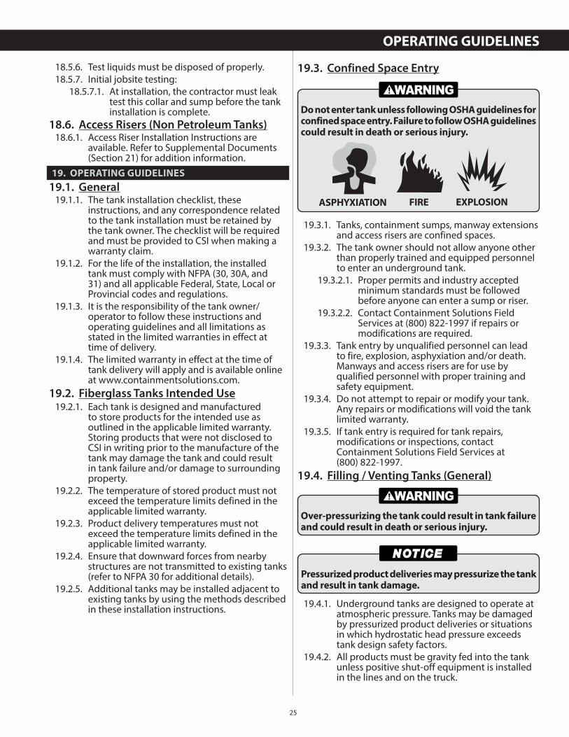
ASPHYXIATION FIRE EXPLOSION
Do not enter tank unless following OSHA guidelines for confined space entry. Failure to follow OSHA guidelines could result in death or serious injury.
PIPING & BOTTOM SUMP CLEARANCES / VENTING / FILLING TANKS
23
16.1. The load bearing capacity for a standard 22” manway installed is 1,200 lbs. for single-walltanks and 2,400 lbs. for double-wall tanks.
16.2. All 30” and 36” manways have a load bearing capacity of 2,400 lbs.
16.3. Do not exceed 50 ft./lb. torque during bolt tightening or manway flange damage may occur.
17. TANK ANNULAR SPACE MONITORING
17.1. Hydrostatic Monitoring17.1.1. Because of its superior leak detection
capability, Containment Solutions recommends the Hydrostatic Tank Monitor for continuous monitoring of the annular space. However, the tank owner or the tank owner’s representative is responsible for selecting the monitoring system.
17.1.2. Tanks with hydrostatic monitoring systems normally arrive with monitoring fluid installed in the annular space and some fluid in the reservoir.
17.1.2.1. After installation, the fluid level in the reservoir must be filled to the proper level.
17.1.2.2. Additional monitoring fluid is supplied with the tank for this purpose.
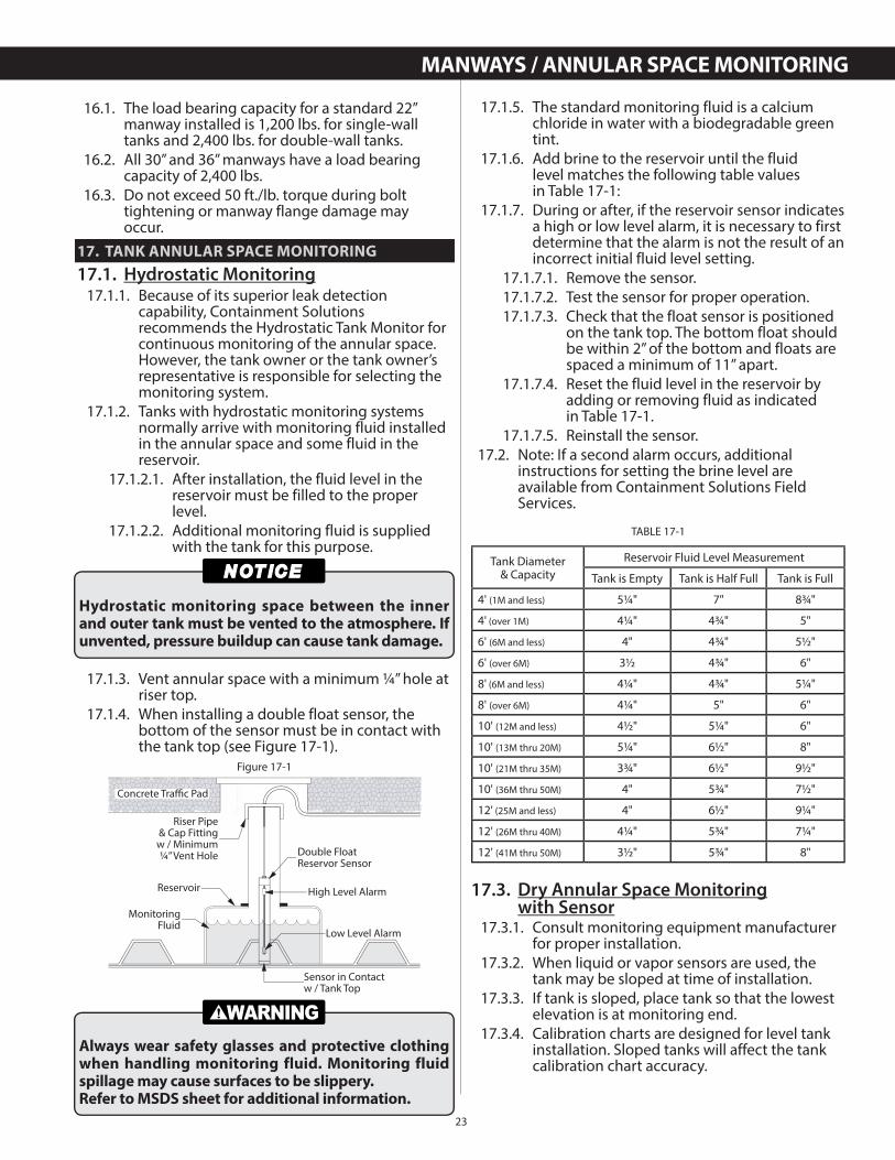
17.1.3. Vent annular space with a minimum ¼” hole at riser top.
17.1.4. When installing a double float sensor, the bottom of the sensor must be in contact with the tank top (see Figure 17-1).
Hydrostatic monitoring space between the inner and outer tank must be vented to the atmosphere. If unvented, pressure buildup can cause tank damage.
Always wear safety glasses and protective clothing when handling monitoring fluid. Monitoring fluid spillage may cause surfaces to be slippery.Refer to MSDS sheet for additional information.
Concrete Traffic Pad
Riser Pipe& Cap Fittingw / Minimum¼” Vent Hole
Reservoir
MonitoringFluid
Sensor in Contactw / Tank Top
Double FloatReservor Sensor
High Level Alarm
Low Level Alarm
Figure 17-1
17.1.5. The standard monitoring fluid is a calcium chloride in water with a biodegradable green tint.
17.1.6. Add brine to the reservoir until the fluidlevel matches the following table valuesin Table 17-1:
17.1.7. During or after, if the reservoir sensor indicates a high or low level alarm, it is necessary to first determine that the alarm is not the result of an incorrect initial fluid level setting.
17.1.7.1. Remove the sensor.17.1.7.2. Test the sensor for proper operation.17.1.7.3. Check that the float sensor is positioned
on the tank top. The bottom float should be within 2” of the bottom and floats are spaced a minimum of 11” apart.
17.1.7.4. Reset the fluid level in the reservoir by adding or removing fluid as indicatedin Table 17-1.
17.1.7.5. Reinstall the sensor.17.2. Note: If a second alarm occurs, additional
instructions for setting the brine level are available from Containment Solutions Field Services.
17.3. Dry Annular Space Monitoringwith Sensor
17.3.1. Consult monitoring equipment manufacturer for proper installation.
17.3.2. When liquid or vapor sensors are used, the tank may be sloped at time of installation.
17.3.3. If tank is sloped, place tank so that the lowest elevation is at monitoring end.
17.3.4. Calibration charts are designed for level tank installation. Sloped tanks will affect the tank calibration chart accuracy.
TABLE 17-1
Tank Diameter& Capacity
Reservoir Fluid Level Measurement
Tank is Empty Tank is Half Full Tank is Full
4' (1M and less) 5¼" 7" 8¾"
4' (over 1M) 4¼" 4¾" 5"
6' (6M and less) 4" 4¾" 5½"
6' (over 6M) 3½ 4¾" 6"
8' (6M and less) 4¼" 4¾" 5¼"
8' (over 6M) 4¼" 5" 6"
10' (12M and less) 4½" 5¼" 6"
10' (13M thru 20M) 5¼" 6½" 8"
10' (21M thru 35M) 3¾" 6½" 9½"
10' (36M thru 50M) 4" 5¾" 7½"
12' (25M and less) 4" 6½" 9¼"
12' (26M thru 40M) 4¼" 5¾" 7¼"
12' (41M thru 50M) 3½" 5¾" 8"
MANWAYS / ANNULAR SPACE MONITORING
24
17.3.5. Use a wire puller to position sensor at the tank bottom.
17.3.6. For ease of installation insert the sensor in the tank cavity before installing the monitoring riser pipe to grade. Use a minimum 4” riser to grade for removal and replacement of sensor.
17.3.7. CSI recommends a permanent pull cable be installed and accessible at grade to facilitate periodic sensor inspections.
17.3.8. For dry monitored double-wall tanks, annular space does not need to be vented.
17.4. Dry Annular Space Vacuum or Air Pressure Monitoring
17.4.1. Consult monitoring equipment manufacturer for proper installation.
17.4.2. Maximum vacuum for continuous monitoring is 5 psig utilizing an approved vacuum monitoring system with a vacuum make-up pump.
17.4.3. Maximum pressure for continuous air pressure monitoring is 3 psig utilizing an approved monitoring system with a make-up pump. Ensure the system is designed to prevent over pressurization of the annular space as tank damage may occur.
18. CONTAINMENT COLLARS,TANK SUMPS & TANK RISERS
18.1. CSI single and double-wall containment collars are factory installed to the tank top to provide a means of secondarily containing leaks from pumps and piping.
18.2. CSI tank sumps are designed to provide a watertight connection to the tank collarutilizing an adhesive joint.
18.3. All Tank Collars And Sumps:18.3.1. Must be continuously monitored for leaks
using an electronic leak monitoring sensor.
In freezing conditions, protect collar and sump from water accumulation. Freezing water may cause damage.
Secondary containment collar must be continuously monitored for potential spills or leaks.
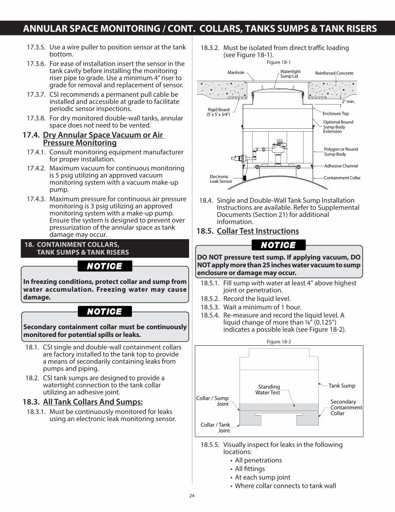
18.3.2. Must be isolated from direct traffic loading(see Figure 18-1).
18.4. Single and Double-Wall Tank Sump Installation Instructions are available. Refer to Supplemental Documents (Section 21) for additional information.
18.5. Collar Test Instructions
18.5.1. Fill sump with water at least 4" above highest joint or penetration.
18.5.2. Record the liquid level.18.5.3. Wait a minimum of 1 hour.18.5.4. Re-measure and record the liquid level. A
liquid change of more than 1⁄8" (0.125") indicates a possible leak (see Figure 18-2).
18.5.5. Visually inspect for leaks in the following locations:
• All penetrations • All fi ttings • At each sump joint • Where collar connects to tank wall
2" min.
Rigid Board(5' x 5' x 3/4")
Manhole WatertightSump Lid
Reinforced Concrete
Containment Collar
Optional RoundSump BodyExtension
Polygon or RoundSump Body
ElectronicLeak Sensor
Adhesive Channel
Enclosure Top
Figure 18-1
DO NOT pressure test sump. If applying vacuum, DO NOT apply more than 25 inches water vacuum to sump enclosure or damage may occur.
Collar / TankJoint
Collar / SumpJoint
Tank SumpStandingWater Test
SecondaryContainmentCollar
Figure 18-2
ANNULAR SPACE MONITORING / CONT. COLLARS, TANKS SUMPS & TANK RISERS
25
OPERATING GUIDELINES
18.5.6. Test liquids must be disposed of properly. 18.5.7. Initial jobsite testing:
18.5.7.1. At installation, the contractor must leak test this collar and sump before the tank installation is complete.
18.6. Access Risers (Non Petroleum Tanks)18.6.1. Access Riser Installation Instructions are
available. Refer to Supplemental Documents (Section 21) for addition information.
19. OPERATING GUIDELINES
19.1. General19.1.1. The tank installation checklist, these
instructions, and any correspondence related to the tank installation must be retained by the tank owner. The checklist will be required and must be provided to CSI when making a warranty claim.
19.1.2. For the life of the installation, the installed tank must comply with NFPA (30, 30A, and 31) and all applicable Federal, State, Local or Provincial codes and regulations.
19.1.3. It is the responsibility of the tank owner/operator to follow these instructions and operating guidelines and all limitations as stated in the limited warranties in effect at time of delivery.
19.1.4. The limited warranty in effect at the time of tank delivery will apply and is available online at www.containmentsolutions.com.
19.2. Fiberglass Tanks Intended Use19.2.1. Each tank is designed and manufactured
to store products for the intended use as outlined in the applicable limited warranty. Storing products that were not disclosed to CSI in writing prior to the manufacture of the tank may damage the tank and could result in tank failure and/or damage to surrounding property.
19.2.2. The temperature of stored product must not exceed the temperature limits defined in the applicable limited warranty.
19.2.3. Product delivery temperatures must not exceed the temperature limits defined in the applicable limited warranty.
19.2.4. Ensure that downward forces from nearby structures are not transmitted to existing tanks (refer to NFPA 30 for additional details).
19.2.5. Additional tanks may be installed adjacent to existing tanks by using the methods described in these installation instructions.
19.3. Confined Space Entry
19.3.1. Tanks, containment sumps, manway extensions and access risers are confined spaces.
19.3.2. The tank owner should not allow anyone other than properly trained and equipped personnel to enter an underground tank.
19.3.2.1. Proper permits and industry accepted minimum standards must be followed before anyone can enter a sump or riser.
19.3.2.2. Contact Containment Solutions Field Services at (800) 822-1997 if repairs or modifications are required.
19.3.3. Tank entry by unqualified personnel can lead to fire, explosion, asphyxiation and/or death. Manways and access risers are for use by qualified personnel with proper training and safety equipment.
19.3.4. Do not attempt to repair or modify your tank. Any repairs or modifications will void the tank limited warranty.
19.3.5. If tank entry is required for tank repairs, modifications or inspections, contact Containment Solutions Field Services at(800) 822-1997.
19.4. Filling / Venting Tanks (General)
19.4.1. Underground tanks are designed to operate at atmospheric pressure. Tanks may be damaged by pressurized product deliveries or situations in which hydrostatic head pressure exceeds tank design safety factors.
19.4.2. All products must be gravity fed into the tank unless positive shut-off equipment is installed in the lines and on the truck.
ASPHYXIATION FIRE EXPLOSION
Do not enter tank unless following OSHA guidelines for confined space entry. Failure to follow OSHA guidelines could result in death or serious injury.
Over-pressurizing the tank could result in tank failure and could result in death or serious injury.
Pressurized product deliveries may pressurize the tank and result in tank damage.
26
19.4.3. If the delivery vehicle uses pumps to fill the tank, precautions must be taken as outlined in the "Filling Tanks" section of this manual.
19.4.3.1. Product delivery from vehicles using pressure in the ullage is not allowed.
19.4.4. The tank's venting system must be adequately sized to ensure that atmospheric pressure is maintained at all times, including when filling and emptying the tank.
19.4.4.1. For tanks with inlet or outlet piping that will result in pressure at the tank top, the pressure should be limited to 1 psig.
19.5. For UL/ULC tanks, The Petroleum Equipment Institute has published several recommended practices (PEI/RP900 and PEI/RP1200) that address proper maintenance, inspection and testing of overfill prevention equipment. Tank owners should obtain a copy of the documents at http://www.pei.org. In addition, the Fiberglass Tank and Pipe Institute has published a white paper on the adverse effects of using vent restriction devices such as ball-float valves and the unintended consequences that may occur see http://www.fiberglasstankandpipe.com.
19.6. The owner must make sure the tank is properly vented at all times as described in the venting section of this manual. Vent piping should be properly installed and unobstructed.
19.7. Do not use ball float valve for overfill protection.19.8. For tanks with vapor recovery systems, the
pressure or vacuum cannot exceed 1 psig.19.9. It is strongly recommended that the tank be
gravity filled and that the owner regularly inspect the automatic shut off device or vent restriction device for proper operation.
19.10. Proper grounding of the drop tube/fill line is important to prevent static discharge during filling.
19.11. If flooding may occur, precautions should be taken to prevent tank float and equipment damage. See EPA "Underground Storage Tanks Flood Guide". See Ballasting section in these instructions should ballasting tanks be required.
19.12. Containment Sumps, Manway Extensions, and Access Risers
19.12.1. Tank owner must leak test the collar and containment sump after any damage, repairs, modifications or to meet regulatory requirements.
19.12.2. UL/ULC sumps must be continuously monitored with an electronic leak detector for potential spills or leaks.
19.12.3. Gaskets are consumable products which will have to be replaced periodically or when it shows a leak during a tightness test.
20. CONVERSION FORMULAS
20.1. Use this as a guide if a dimension does not have a metric conversion printed.
LENGTH WEIGHT
mm = millimeters kg = kilogram• 1" = 25.4 mm • 1lb = 0.454 kg• 1' = 304.8 mm
PRESSURE CAPACITY
kPa = kilopascals L = liters• 1 psi = 6.894 kPa • 1 gal = 3.785 L
21. SUPPLEMENTAL DOCUMENTS
21.1. Supplemental documents, which may apply to specific installations and / or conditions, are available upon request from Containment Solutions Technical Support.
• Single-Wall Tank Sump Installation Instructions (Pub. No. INST 6030)
• Double-Wall Tank Sump Installation Instructions (Pub. No. INST 6034)
• Access Riser Installation Instructions w/ Adhesive Channels (Pub. No. INST 6056)
• Standard Hold Down Strap Anchor System(Pub. No. INST 6062)
• Split Strap Anchor System(Pub. No. INST 6063)
• Wire Rope over Tank Top(Pub. No. INST 6047)
• Fiberglass Tanks Shipping into Canada Installation Instructions(Pub. No. INST 6043-CAN)
• Urea DEF Installation Instructions(Pub. No. INST 6052)
• Triple-Wall Tank Installation Instructions(Pub. No. INST 6045)
• NYC Special Installation Instructions(Pub. No. INST 6008)
• Fiberglass Oil/Water Separator TankInstallation and Start-Up Instructions(Pub. No. OWS 2013)
• Alternate Backfi ll Above Tank TopInstallation Instructions (Pub. No. INST 6014)
• Berm Installation Instructions(Pub. No. 6022)
• Bottom Sump Installation Instructions (Pub. No. INST 6044)
• Flexible Connector Specifi cation(SPEC 9005)
• Brine Monitoring Fluid MSDS Sheet(Pub. No. 15002)
• Lifting Tanks with Slings (Pub. No. 6021)
OPERATING GUIDELINES / CONVERSION FORMULAS / SUPPLEMENTAL DOCS
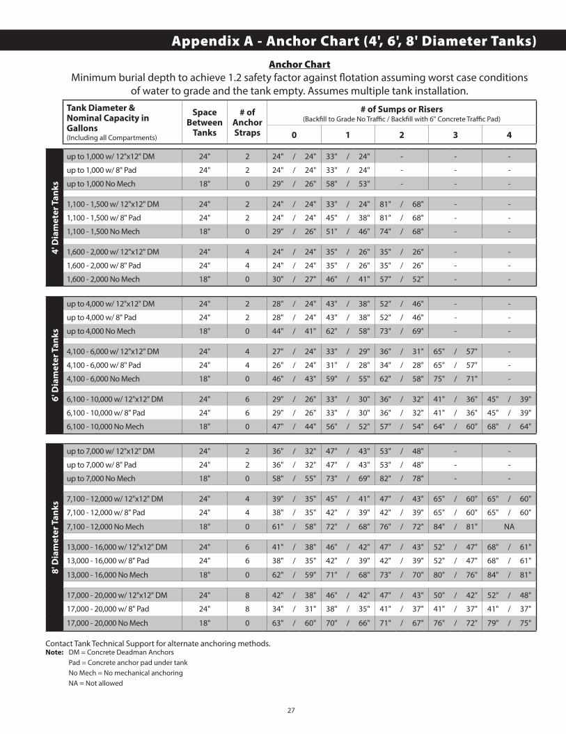
27
Contact Tank Technical Support for alternate anchoring methods.Note: DM = Concrete Deadman Anchors Pad = Concrete anchor pad under tank No Mech = No mechanical anchoring NA = Not allowed
4' D
iam
ete
r T
an
ks
up to 1,000 w/ 12"x12" DM 24" 2 24" / 24" 33" / 24" - - -
up to 1,000 w/ 8" Pad 24" 2 24" / 24" 33" / 24" - - -
up to 1,000 No Mech 18" 0 29" / 26" 58" / 53" - - -
1,100 - 1,500 w/ 12"x12" DM 24" 2 24" / 24" 33" / 24" 81" / 68" - -
1,100 - 1,500 w/ 8" Pad 24" 2 24" / 24" 45" / 38" 81" / 68" - -
1,100 - 1,500 No Mech 18" 0 29" / 26" 51" / 46" 74" / 68" - -
1,600 - 2,000 w/ 12"x12" DM 24" 4 24" / 24" 35" / 26" 35" / 26" - -
1,600 - 2,000 w/ 8" Pad 24" 4 24" / 24" 35" / 26" 35" / 26" - -
1,600 - 2,000 No Mech 18" 0 30" / 27" 46" / 41" 57" / 52" - -
6' D
iam
ete
r T
an
ks
up to 4,000 w/ 12"x12" DM 24" 2 28" / 24" 43" / 38" 52" / 46" - -
up to 4,000 w/ 8" Pad 24" 2 28" / 24" 43" / 38" 52" / 46" - -
up to 4,000 No Mech 18" 0 44" / 41" 62" / 58" 73" / 69" - -
4,100 - 6,000 w/ 12"x12" DM 24" 4 27" / 24" 33" / 29" 36" / 31" 65" / 57" -
4,100 - 6,000 w/ 8" Pad 24" 4 26" / 24" 31" / 28" 34" / 28" 65" / 57" -
4,100 - 6,000 No Mech 18" 0 46" / 43" 59" / 55" 62" / 58" 75" / 71" -
6,100 - 10,000 w/ 12"x12" DM 24" 6 29" / 26" 33" / 30" 36" / 32" 41" / 36" 45" / 39"
6,100 - 10,000 w/ 8" Pad 24" 6 29" / 26" 33" / 30" 36" / 32" 41" / 36" 45" / 39"
6,100 - 10,000 No Mech 18" 0 47" / 44" 56" / 52" 57" / 54" 64" / 60" 68" / 64"
8' D
iam
ete
r T
an
ks
up to 7,000 w/ 12"x12" DM 24" 2 36" / 32" 47" / 43" 53" / 48" - -
up to 7,000 w/ 8" Pad 24" 2 36" / 32" 47" / 43" 53" / 48" - -
up to 7,000 No Mech 18" 0 58" / 55" 73" / 69" 82" / 78" - -
7,100 - 12,000 w/ 12"x12" DM 24" 4 39" / 35" 45" / 41" 47" / 43" 65" / 60" 65" / 60"
7,100 - 12,000 w/ 8" Pad 24" 4 38" / 35" 42" / 39" 42" / 39" 65" / 60" 65" / 60"
7,100 - 12,000 No Mech 18" 0 61" / 58" 72" / 68" 76" / 72" 84" / 81" NA
13,000 - 16,000 w/ 12"x12" DM 24" 6 41" / 38" 46" / 42" 47" / 43" 52" / 47" 68" / 61"
13,000 - 16,000 w/ 8" Pad 24" 6 38" / 35" 42" / 39" 42" / 39" 52" / 47" 68" / 61"
13,000 - 16,000 No Mech 18" 0 62" / 59" 71" / 68" 73" / 70" 80" / 76" 84" / 81"
17,000 - 20,000 w/ 12"x12" DM 24" 8 42" / 38" 46" / 42" 47" / 43" 50" / 42" 52" / 48"
17,000 - 20,000 w/ 8" Pad 24" 8 34" / 31" 38" / 35" 41" / 37" 41" / 37" 41" / 37"
17,000 - 20,000 No Mech 18" 0 63" / 60" 70" / 66" 71" / 67" 76" / 72" 79" / 75"
Anchor ChartMinimum burial depth to achieve 1.2 safety factor against fl otation assuming worst case conditions
of water to grade and the tank empty. Assumes multiple tank installation.Tank Diameter &Nominal Capacity inGallons(Including all Compartments)
SpaceBetween
Tanks
# of Anchor Straps
# of Sumps or Risers(Backfi ll to Grade No Traffi c / Backfi ll with 6" Concrete Traffi c Pad)
0 1 2 3 4
Appendix A - Anchor Chart (4', 6', 8' Diameter Tanks)
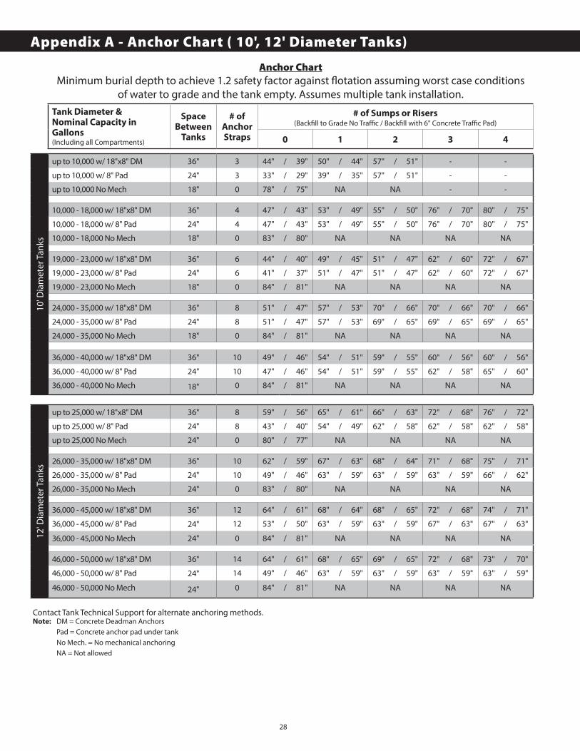
28
10' D
iam
eter
Tan
ks
up to 10,000 w/ 18"x8" DM 36" 3 44" / 39" 50" / 44" 57" / 51" - -
up to 10,000 w/ 8" Pad 24" 3 33" / 29" 39" / 35" 57" / 51" - -
up to 10,000 No Mech 18" 0 78" / 75" NA NA - -
10,000 - 18,000 w/ 18"x8" DM 36" 4 47" / 43" 53" / 49" 55" / 50" 76" / 70" 80" / 75"
10,000 - 18,000 w/ 8" Pad 24" 4 47" / 43" 53" / 49" 55" / 50" 76" / 70" 80" / 75"
10,000 - 18,000 No Mech 18" 0 83" / 80" NA NA NA NA
19,000 - 23,000 w/ 18"x8" DM 36" 6 44" / 40" 49" / 45" 51" / 47" 62" / 60" 72" / 67"
19,000 - 23,000 w/ 8" Pad 24" 6 41" / 37" 51" / 47" 51" / 47" 62" / 60" 72" / 67"
19,000 - 23,000 No Mech 18" 0 84" / 81" NA NA NA NA
24,000 - 35,000 w/ 18"x8" DM 36" 8 51" / 47" 57" / 53" 70" / 66" 70" / 66" 70" / 66"
24,000 - 35,000 w/ 8" Pad 24" 8 51" / 47" 57" / 53" 69" / 65" 69" / 65" 69" / 65"
24,000 - 35,000 No Mech 18" 0 84" / 81" NA NA NA NA
36,000 - 40,000 w/ 18"x8" DM 36" 10 49" / 46" 54" / 51" 59" / 55" 60" / 56" 60" / 56"
36,000 - 40,000 w/ 8" Pad 24" 10 47" / 46" 54" / 51" 59" / 55" 62" / 58" 65" / 60"
36,000 - 40,000 No Mech 18" 0 84" / 81" NA NA NA NA
12' D
iam
eter
Tan
ks
up to 25,000 w/ 18"x8" DM 36" 8 59" / 56" 65" / 61" 66" / 63" 72" / 68" 76" / 72"
up to 25,000 w/ 8" Pad 24" 8 43" / 40" 54" / 49" 62" / 58" 62" / 58" 62" / 58"
up to 25,000 No Mech 24" 0 80" / 77" NA NA NA NA
26,000 - 35,000 w/ 18"x8" DM 36" 10 62" / 59" 67" / 63" 68" / 64" 71" / 68" 75" / 71"
26,000 - 35,000 w/ 8" Pad 24" 10 49" / 46" 63" / 59" 63" / 59" 63" / 59" 66" / 62"
26,000 - 35,000 No Mech 24" 0 83" / 80" NA NA NA NA
36,000 - 45,000 w/ 18"x8" DM 36" 12 64" / 61" 68" / 64" 68" / 65" 72" / 68" 74" / 71"
36,000 - 45,000 w/ 8" Pad 24" 12 53" / 50" 63" / 59" 63" / 59" 67" / 63" 67" / 63"
36,000 - 45,000 No Mech 24" 0 84" / 81" NA NA NA NA
46,000 - 50,000 w/ 18"x8" DM 36" 14 64" / 61" 68" / 65" 69" / 65" 72" / 68" 73" / 70"
46,000 - 50,000 w/ 8" Pad 24" 14 49" / 46" 63" / 59" 63" / 59" 63" / 59" 63" / 59"
46,000 - 50,000 No Mech 24" 0 84" / 81" NA NA NA NA
Anchor ChartMinimum burial depth to achieve 1.2 safety factor against fl otation assuming worst case conditions
of water to grade and the tank empty. Assumes multiple tank installation.Tank Diameter &Nominal Capacity inGallons(Including all Compartments)
SpaceBetween
Tanks
# of Anchor Straps
# of Sumps or Risers(Backfi ll to Grade No Traffi c / Backfi ll with 6" Concrete Traffi c Pad)
0 1 2 3 4
Contact Tank Technical Support for alternate anchoring methods.Note: DM = Concrete Deadman Anchors Pad = Concrete anchor pad under tank No Mech. = No mechanical anchoring NA = Not allowed
Appendix A - Anchor Chart ( 10', 12' Diameter Tanks)
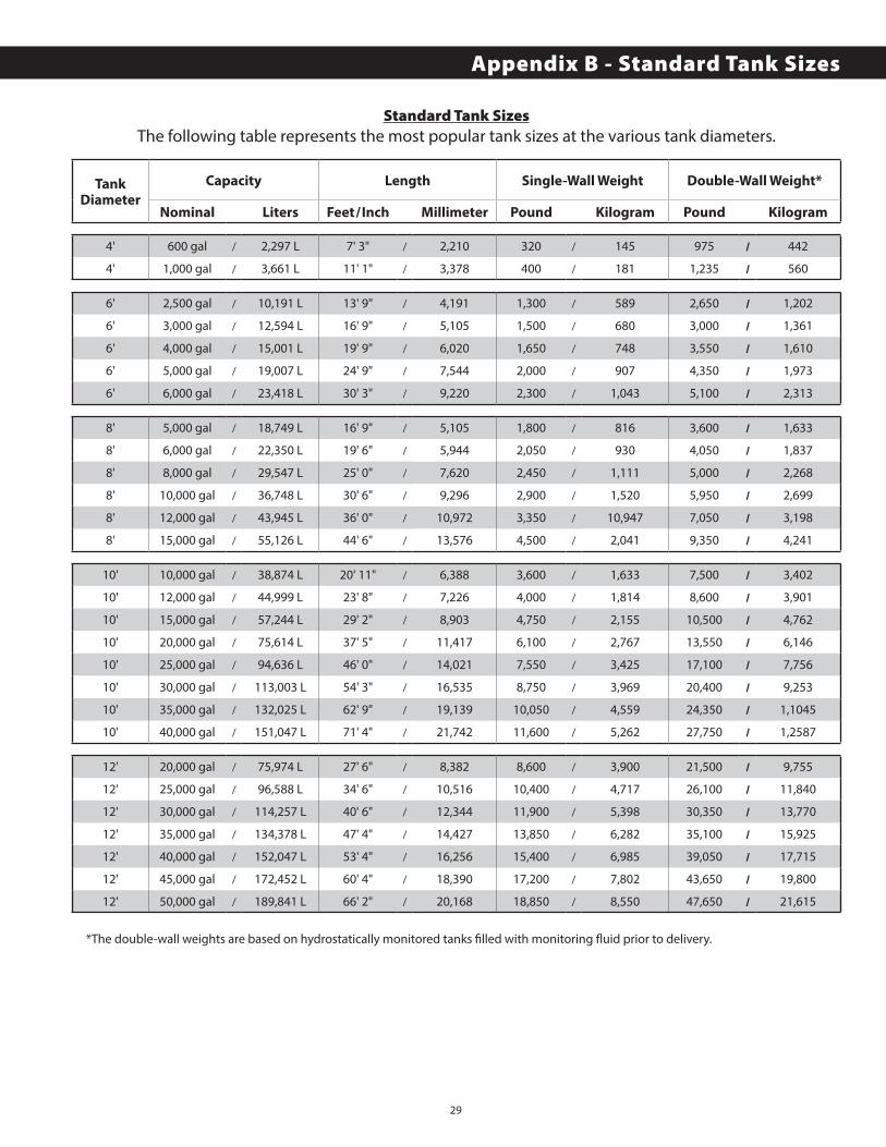
29
Standard Tank SizesThe following table represents the most popular tank sizes at the various tank diameters.
TankDiameter
Capacity Length Single-Wall Weight Double-Wall Weight*
Nominal Liters Feet/Inch Millimeter Pound Kilogram Pound Kilogram/ / / /
4' 600 gal / 2,297 L 7' 3" / 2,210 320 / 145 975 / 442
4' 1,000 gal / 3,661 L 11' 1" / 3,378 400 / 181 1,235 / 560/ / / /
6' 2,500 gal / 10,191 L 13' 9" / 4,191 1,300 / 589 2,650 / 1,202
6' 3,000 gal / 12,594 L 16' 9" / 5,105 1,500 / 680 3,000 / 1,361
6' 4,000 gal / 15,001 L 19' 9" / 6,020 1,650 / 748 3,550 / 1,610
6' 5,000 gal / 19,007 L 24' 9" / 7,544 2,000 / 907 4,350 / 1,973
6' 6,000 gal / 23,418 L 30' 3" / 9,220 2,300 / 1,043 5,100 / 2,313/ / / /
8' 5,000 gal / 18,749 L 16' 9" / 5,105 1,800 / 816 3,600 / 1,633
8' 6,000 gal / 22,350 L 19' 6" / 5,944 2,050 / 930 4,050 / 1,837
8' 8,000 gal / 29,547 L 25' 0" / 7,620 2,450 / 1,111 5,000 / 2,268
8' 10,000 gal / 36,748 L 30' 6" / 9,296 2,900 / 1,520 5,950 / 2,699
8' 12,000 gal / 43,945 L 36' 0" / 10,972 3,350 / 10,947 7,050 / 3,198
8' 15,000 gal / 55,126 L 44' 6" / 13,576 4,500 / 2,041 9,350 / 4,241/ / / /
10' 10,000 gal / 38,874 L 20' 11" / 6,388 3,600 / 1,633 7,500 / 3,402
10' 12,000 gal / 44,999 L 23' 8" / 7,226 4,000 / 1,814 8,600 / 3,901
10' 15,000 gal / 57,244 L 29' 2" / 8,903 4,750 / 2,155 10,500 / 4,762
10' 20,000 gal / 75,614 L 37' 5" / 11,417 6,100 / 2,767 13,550 / 6,146
10' 25,000 gal / 94,636 L 46' 0" / 14,021 7,550 / 3,425 17,100 / 7,756
10' 30,000 gal / 113,003 L 54' 3" / 16,535 8,750 / 3,969 20,400 / 9,253
10' 35,000 gal / 132,025 L 62' 9" / 19,139 10,050 / 4,559 24,350 / 1,1045
10' 40,000 gal / 151,047 L 71' 4" / 21,742 11,600 / 5,262 27,750 / 1,2587/ / / /
12' 20,000 gal / 75,974 L 27' 6" / 8,382 8,600 / 3,900 21,500 / 9,755
12' 25,000 gal / 96,588 L 34' 6" / 10,516 10,400 / 4,717 26,100 / 11,840
12' 30,000 gal / 114,257 L 40' 6" / 12,344 11,900 / 5,398 30,350 / 13,770
12' 35,000 gal / 134,378 L 47' 4" / 14,427 13,850 / 6,282 35,100 / 15,925
12' 40,000 gal / 152,047 L 53' 4" / 16,256 15,400 / 6,985 39,050 / 17,715
12' 45,000 gal / 172,452 L 60' 4" / 18,390 17,200 / 7,802 43,650 / 19,800
12' 50,000 gal / 189,841 L 66' 2" / 20,168 18,850 / 8,550 47,650 / 21,615
*The double-wall weights are based on hydrostatically monitored tanks fi lled with monitoring fl uid prior to delivery.
Appendix B - Standard Tank Sizes
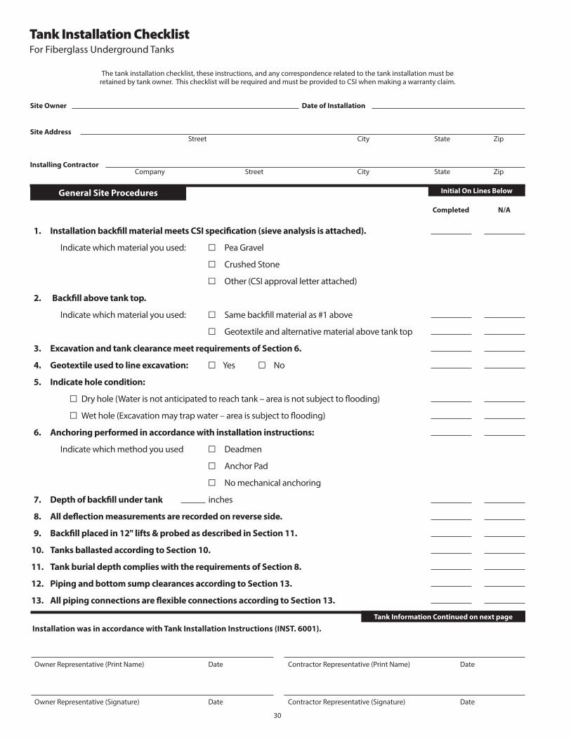
30
Initial On Lines Below
Tank Installation ChecklistFor Fiberglass Underground Tanks
The tank installation checklist, these instructions, and any correspondence related to the tank installation must beretained by tank owner. This checklist will be required and must be provided to CSI when making a warranty claim.
Site Owner Date of Installation
Site AddressStreet City State Zip
Installing ContractorCompany Street City State Zip
Completed N/A
1. Installation backfi ll material meets CSI specifi cation (sieve analysis is attached).
Indicate which material you used: □ Pea Gravel
□ Crushed Stone
□ Other (CSI approval letter attached)
2. Backfi ll above tank top.
Indicate which material you used: □ Same backfi ll material as #1 above
□ Geotextile and alternative material above tank top
3. Excavation and tank clearance meet requirements of Section 6.
4. Geotextile used to line excavation: □ Yes □ No
5. Indicate hole condition:
□ Dry hole (Water is not anticipated to reach tank – area is not subject to fl ooding)
□ Wet hole (Excavation may trap water – area is subject to fl ooding)
6. Anchoring performed in accordance with installation instructions:
Indicate which method you used □ Deadmen
□ Anchor Pad
□ No mechanical anchoring
7. Depth of backfi ll under tank inches
8. All defl ection measurements are recorded on reverse side.
9. Backfi ll placed in 12" lifts & probed as described in Section 11.
10. Tanks ballasted according to Section 10.
11. Tank burial depth complies with the requirements of Section 8.
12. Piping and bottom sump clearances according to Section 13.
13. All piping connections are fl exible connections according to Section 13.
Installation was in accordance with Tank Installation Instructions (INST. 6001).
Owner Representative (Signature) Date Contractor Representative (Signature) Date
General Site Procedures
Tank Information Continued on next page
Owner Representative (Print Name) Date Contractor Representative (Print Name) Date
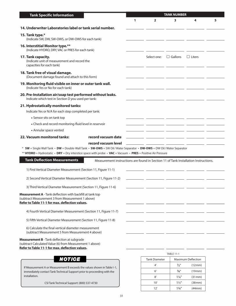
31
TANK NUMBER
1 2 3 4 5
14. Underwriter Laboratories label or tank serial number.
15. Tank type.*(Indicate SW, DW, SW-OWS, or DW-OWS for each tank)
16. Interstitial Monitor type.**(Indicate HYDRO, DRY, VAC or PRES for each tank)
17. Tank capacity. Select one: □ Gallons □ Liters(Indicate unit of measurement and record the capacities for each tank)
18. Tank free of visual damage.(Document damage found and attach to this form)
19. Monitoring fl uid visible on inner or outer tank wall.(Indicate Yes or No for each tank)
20. Pre-Installation air/soap test performed without leaks.Indicate which test in Section D you used per tank:
21. Hydrostatically monitored tanks:
Indicate Yes or N/A for each step completed per tank:
• Sensor sits on tank top
• Check and record monitoring-fl uid level in reservoir
• Annular space vented
22. Vacuum monitored tanks: record vacuum date
record vacuum level
1) First Vertical Diameter Measurement (Section 11, Figure 11-1)
2) Second Vertical Diameter Measurement (Section 11, Figure 11-2)
3) Third Vertical Diameter Measurement (Section 11, Figure 11-6)
Measurement A - Tank defl ection with backfi ll at tank top(subtract Measurement 3 from Measurement 1 above)Refer to Table 11-1 for max. defl ection values.
4) Fourth Vertical Diameter Measurement (Section 11, Figure 11-7)
5) Fifth Vertical Diameter Measurement (Section 11, Figure 11-8)
6) Calculate the fi nal vertical diameter measurement(subtract Measurement 5 from Measurement 4 above)
Measurement B - Tank defl ection at subgrade (subtract Calculated Value (6) from Measurement 1 above)Refer to Table 11-1 for max. defl ection values.
Tank Deflection Measurements
Tank Specific Information
Measurement instructions are found in Section 11 of Tank Installation Instructions.
If Measurement A or Measurement B exceeds the values shown in Table I -1, immediately contact Tank Technical Support prior to proceeding with the installation.
CSI Tank Technical Support: (800) 537-4730
* SW = Single Wall Tank • DW = Double-Wall Tank • SW-OWS = SW Oil / Water Separator • DW-OWS = DW Oil / Water Separator
** HYDRO = Hydrostatic • DRY = Dry interstice space with probe • VAC = Vacuum • PRES = Positive Air Pressure
Tank Diameter Maximum Deflection
4' ½" (12mm)
6' ¾" (19mm)
8' 1¼" (31mm)
10' 1½" (38mm)
12' 1¾" (44mm)
TABLE 11-1

333 North Rivershire Drive • Suite 190 • Conroe, TX 77304Phone: 936-756-7731 • Fax 936-756-7766
www.containmentsolutions.com
© 2015 • Containment Solutions, Inc. • All Rights Reserved • The Containment Solutions logo is a trademark of Containment Solutions, Inc. • 06-15. Pub. No. INST 6001J
Technical Support
(800) 537-4730Fax: (936) 756-7665
Field Service
(800) 822-1997Fax: (814) 542-5020
Tank Sales
(877) 274-8265Fax: (936) 756-7665