Embed Size (px)
Citation preview
** WARNING ** WARNING ** WARNING ** WARNING **This document is intended for informational purposes only.
Users are cautioned that California Department of Transportation (Department) does not assume any liability or responsibility based on these electronic files or for any defective or incomplete copying, exerpting, scanning, faxing or downloading of the contract documents. As always, for the official paper versions of the bidders packages and non-bidder packages, including addenda write to the California Department of Transportation, Plans and Bid Documents, Room 0200, P.O. Box 942874, Sacramento, CA 94272-0001, telephone (916) 654-4490 or fax (916) 654-7028. Office hours are 7:30 a.m. to 4:15 p.m. When ordering bidder or non-bidder packages it is important that you include a telephone number and fax number, P.O. Box and street address so that you can receive addenda.
etric
Caltrans
STATE OF CALIFORNIA
DEPARTMENT OF TRANSPORTATION__________________________________________________________
NOTICE TO CONTRACTORSAND
SPECIAL PROVISIONSFOR CONSTRUCTION ON STATE HIGHWAY IN
AT VARIOUS LOCATIONS FROM MOULTON PARKWAY TO NEWPORT COAST DRIVE
DISTRICT 12, ROUTE 73
__________________________________________________________
For Use in Connection with Standard Specifications Dated JULY 1999,
Standard Plans Dated JULY 1999, and Labor Surcharge and Equipment Rental Rates.
__________________________________________________________
CONTRACT NO. 12-0C9874
12-Ora-73-20.9/34.6
Federal Aid Project
ACNH-P079(070)E
Bids Open: September 2, 2004Dated: August 2, 2004

*************************************************************************************************
IMPORTANTSPECIAL NOTICES
*************************************************************************************************
Effective September 2, 2003, Triaxial Management Services will no longer provide lists of certified DBEs to contractors bidding on projects or provide DBEs with assistance in preparing bids for subcontracting or supplying materials. Triaxial provided these services for contracts in Districts 01, 02, 03, 04, 05 (except San Luis Obispo and Santa Barbara Counties), 06 (except Kern County), 09 and 10.
Contractors bidding on projects in these Districts may obtain lists of certified DBEs from the Department's Website at http://www.dot.ca.gov/hq/bep. The Department also publishes a quarterly directory of certified firms that may be ordered from the Publications Unit at (916) 445-3520.
Contractors bidding on projects with DBE goals in Districts 05 (San Luis Obispo and Santa Barbara Counties), 06 (Kern County), 07, 08, 11 and 12 may continue to call Padilla & Associates at the telephone numbers listed in the Special Provisions.

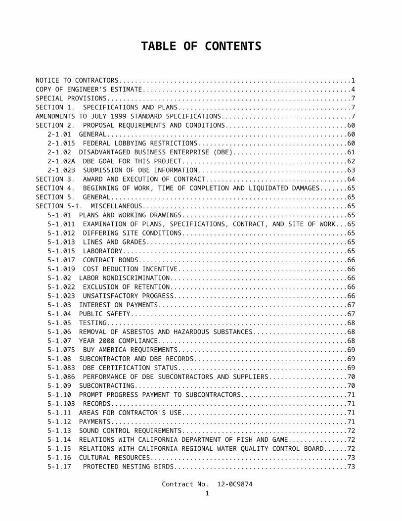
TABLE OF CONTENTS
NOTICE TO CONTRACTORS.............................................................................................................................................1COPY OF ENGINEER'S ESTIMATE..................................................................................................................................4SPECIAL PROVISIONS.......................................................................................................................................................7SECTION 1. SPECIFICATIONS AND PLANS..................................................................................................................7AMENDMENTS TO JULY 1999 STANDARD SPECIFICATIONS..................................................................................7SECTION 2. PROPOSAL REQUIREMENTS AND CONDITIONS................................................................................60
2-1.01 GENERAL........................................................................................................................................................602-1.015 FEDERAL LOBBYING RESTRICTIONS...................................................................................................602-1.02 DISADVANTAGED BUSINESS ENTERPRISE (DBE)................................................................................612-1.02A DBE GOAL FOR THIS PROJECT...............................................................................................................622-1.02B SUBMISSION OF DBE INFORMATION...................................................................................................63
SECTION 3. AWARD AND EXECUTION OF CONTRACT..........................................................................................64SECTION 4. BEGINNING OF WORK, TIME OF COMPLETION AND LIQUIDATED DAMAGES.........................65SECTION 5. GENERAL....................................................................................................................................................65SECTION 5-1. MISCELLANEOUS..................................................................................................................................65
5-1.01 PLANS AND WORKING DRAWINGS.........................................................................................................655-1.011 EXAMINATION OF PLANS, SPECIFICATIONS, CONTRACT, AND SITE OF WORK.......................655-1.012 DIFFERING SITE CONDITIONS.................................................................................................................655-1.013 LINES AND GRADES..................................................................................................................................655-1.015 LABORATORY.............................................................................................................................................655-1.017 CONTRACT BONDS....................................................................................................................................665-1.019 COST REDUCTION INCENTIVE................................................................................................................665-1.02 LABOR NONDISCRIMINATION..................................................................................................................665-1.022 EXCLUSION OF RETENTION....................................................................................................................665-1.023 UNSATISFACTORY PROGRESS................................................................................................................665-1.03 INTEREST ON PAYMENTS..........................................................................................................................675-1.04 PUBLIC SAFETY............................................................................................................................................675-1.05 TESTING..........................................................................................................................................................685-1.06 REMOVAL OF ASBESTOS AND HAZARDOUS SUBSTANCES..............................................................685-1.07 YEAR 2000 COMPLIANCE...........................................................................................................................685-1.075 BUY AMERICA REQUIREMENTS.............................................................................................................695-1.08 SUBCONTRACTOR AND DBE RECORDS.................................................................................................695-1.083 DBE CERTIFICATION STATUS.................................................................................................................695-1.086 PERFORMANCE OF DBE SUBCONTRACTORS AND SUPPLIERS......................................................705-1.09 SUBCONTRACTING......................................................................................................................................705-1.10 PROMPT PROGRESS PAYMENT TO SUBCONTRACTORS....................................................................715-1.103 RECORDS......................................................................................................................................................715-1.11 AREAS FOR CONTRACTOR'S USE.............................................................................................................715-1.12 PAYMENTS.....................................................................................................................................................715-1.13 SOUND CONTROL REQUIREMENTS.........................................................................................................725-1.14 RELATIONS WITH CALIFORNIA DEPARTMENT OF FISH AND GAME.............................................725-1.15 RELATIONS WITH CALIFORNIA REGIONAL WATER QUALITY CONTROL BOARD.....................725-1.16 CULTURAL RESOURCES.............................................................................................................................735-1.17 PROTECTED NESTING BIRDS...................................................................................................................73
SECTION 6. (BLANK).......................................................................................................................................................74SECTION 7. (BLANK).......................................................................................................................................................74SECTION 8. MATERIALS................................................................................................................................................74SECTION 8-1. MISCELLANEOUS..................................................................................................................................74
8-1.01 SUBSTITUTION OF NON-METRIC MATERIALS AND PRODUCTS......................................................748-1.02 PREQUALIFIED AND TESTED SIGNING AND DELINEATION MATERIALS.....................................80
PAVEMENT MARKERS, PERMANENT TYPE................................................................................................80PAVEMENT MARKERS, TEMPORARY TYPE................................................................................................81STRIPING AND PAVEMENT MARKING MATERIAL...................................................................................81CLASS 1 DELINEATORS....................................................................................................................................82
Contract No. 12-0C98741
CHANNELIZERS.................................................................................................................................................82CONICAL DELINEATORS, 1070 mm................................................................................................................83OBJECT MARKERS.............................................................................................................................................83CONCRETE BARRIER MARKERS AND..........................................................................................................83TEMPORARY RAILING (TYPE K) REFLECTORS..........................................................................................83METAL BEAM GUARD RAIL POST MARKERS............................................................................................84CONCRETE BARRIER DELINEATORS, 400 mm............................................................................................84CONCRETE BARRIER-MOUNTED MINI-DRUM (260 mm x 360 mm x 570 mm).......................................84SOUND WALL DELINEATOR...........................................................................................................................84GUARD RAILING DELINEATOR......................................................................................................................84RETROREFLECTIVE SHEETING......................................................................................................................84SPECIALTY SIGNS.............................................................................................................................................85SIGN SUBSTRATE..............................................................................................................................................86
8-1.03 SLAG AGGREGATE......................................................................................................................................868-1.04 STATE-FURNISHED MATERIALS..............................................................................................................86
SECTION 8-2. CONCRETE...............................................................................................................................................868-2.01 PORTLAND CEMENT CONCRETE.............................................................................................................86
SECTION 8-3. WELDING.................................................................................................................................................878-3.01 WELDING........................................................................................................................................................87
GENERAL.............................................................................................................................................................87PAYMENT............................................................................................................................................................90
SECTION 9. (BLANK).......................................................................................................................................................90SECTION 10. CONSTRUCTION DETAILS....................................................................................................................90SECTION 10-1. GENERAL...............................................................................................................................................90
10-1.01 ORDER OF WORK.......................................................................................................................................9010-1.02 WATER POLLUTION CONTROL...............................................................................................................90
RETENTION OF FUNDS.....................................................................................................................................91STORM WATER POLLUTION PREVENTION PLAN PREPARATION, APPROVAL AND AMENDMENTS................................................................................................................................................................................92COST BREAK-DOWN.........................................................................................................................................93SWPPP IMPLEMENTATION..............................................................................................................................96MAINTENANCE..................................................................................................................................................97REPORTING REQUIREMENTS.........................................................................................................................97SAMPLING AND ANALYTICAL REQUIREMENTS.......................................................................................98PAYMENT............................................................................................................................................................99
10-1.03 TEMPORARY CONCRETE WASHOUT FACILITY...............................................................................10010-1.04 TEMPORARY SILT FENCE.......................................................................................................................10210-1.05 PRESERVATION OF PROPERTY.............................................................................................................10410-1.06 TEMPORARY GRAVEL BAG BERM.......................................................................................................10410-1.07 TEMPORARY CONSTRUCTION ENTRANCE.......................................................................................10610-1.08 PROGRESS SCHEDULE (CRITICAL PATH METHOD).........................................................................10810-1.09 OBSTRUCTIONS........................................................................................................................................11010-1.10 DUST CONTROL........................................................................................................................................11010-1.11 MOBILIZATION.........................................................................................................................................11010-1.12 CONSTRUCTION AREA TRAFFIC CONTROL DEVICES....................................................................11110-1.13 CONSTRUCTION AREA SIGNS...............................................................................................................11110-1.14 MAINTAINING TRAFFIC..........................................................................................................................11210-1.15 CLOSURE REQUIREMENTS AND CONDITIONS.................................................................................112
CLOSURE SCHEDULE.....................................................................................................................................112CONTINGENCY PLAN.....................................................................................................................................113LATE REOPENING OF CLOSURES................................................................................................................113COMPENSATION..............................................................................................................................................113
10-1.16 TRAFFIC CONTROL SYSTEM FOR LANE CLOSURE..........................................................................11310-1.17 TEMPORARY RAILING............................................................................................................................11410-1.18 CHANNELIZER..........................................................................................................................................11410-1.19 TEMPORARY CRASH CUSHION MODULE..........................................................................................11410-1.20 EXISTING HIGHWAY FACILITIES.........................................................................................................115
ABANDON CULVERT......................................................................................................................................115
Contract No. 12-0C98742

REMOVE CHAIN LINK FENCE.......................................................................................................................116REMOVE GATE.................................................................................................................................................116REMOVE DRAINAGE FACILITY....................................................................................................................116REMOVE COMPOST STORM WATER FILTER STRUCTURE....................................................................116REMOVE ROCK SLOPE PROTECTION.........................................................................................................116REMOVE ASPHALT CONCRETE OVERSIDE DRAIN.................................................................................117ADJUST MANHOLE TO GRADE....................................................................................................................117REMOVE CONCRETE (CURB, GUTTER, AND SIDEWALK)......................................................................117
10-1.21 CLEARING AND GRUBBING...................................................................................................................11710-1.22 EARTHWORK.............................................................................................................................................11710-1.23 QUALITY CONTROL SEED TESTING....................................................................................................11710-1.24 MOVE-IN/MOVE-OUT (EROSION CONTROL)......................................................................................11710-1.25 EROSION CONTROL (TYPE D)................................................................................................................118
MATERIALS.......................................................................................................................................................118APPLICATION...................................................................................................................................................119MEASUREMENT AND PAYMENT.................................................................................................................120
10-1.26 AGGREGATE SUBBASE............................................................................................................................12010-1.27 AGGREGATE BASE...................................................................................................................................12010-1.28 LEAN CONCRETE BASE..........................................................................................................................12010-1.29 ASPHALT CONCRETE..............................................................................................................................12010-1.30 CONCRETE STRUCTURES.......................................................................................................................12010-1.31 REINFORCEMENT.....................................................................................................................................12110-1.32 ALTERNATIVE PIPE.................................................................................................................................12110-1.33 PLASTIC PIPE.............................................................................................................................................12110-1.34 REINFORCED CONCRETE PIPE..............................................................................................................12110-1.35 MISCELLANEOUS FACILITIES...............................................................................................................12110-1.36 MISCELLANEOUS CONCRETE CONSTRUCTION................................................................................12110-1.37 MISCELLANEOUS IRON AND STEEL....................................................................................................12210-1.38 STAINLESS STEEL WIRE MESH.............................................................................................................122
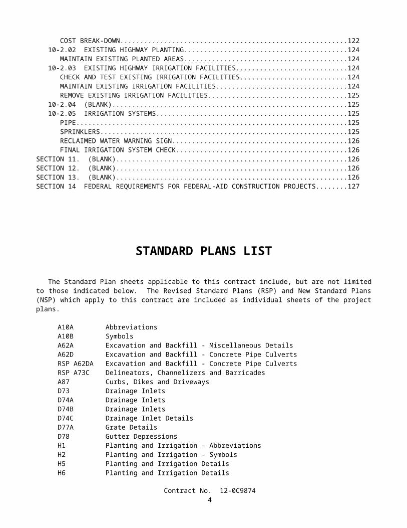
SECTION 10-2 HIGHWAY PLANTING AND IRRIGATION SYSTEMS...................................................................12210-2.01 GENERAL....................................................................................................................................................122
COST BREAK-DOWN.......................................................................................................................................12210-2.02 EXISTING HIGHWAY PLANTING..........................................................................................................124
MAINTAIN EXISTING PLANTED AREAS....................................................................................................12410-2.03 EXISTING HIGHWAY IRRIGATION FACILITIES.................................................................................124
CHECK AND TEST EXISTING IRRIGATION FACILITIES..........................................................................124MAINTAIN EXISTING IRRIGATION FACILITIES.......................................................................................124REMOVE EXISTING IRRIGATION FACILITIES...........................................................................................125
10-2.04 (BLANK)......................................................................................................................................................12510-2.05 IRRIGATION SYSTEMS............................................................................................................................125
PIPE.....................................................................................................................................................................125SPRINKLERS......................................................................................................................................................125RECLAIMED WATER WARNING SIGN........................................................................................................126FINAL IRRIGATION SYSTEM CHECK..........................................................................................................126
SECTION 11. (BLANK)...................................................................................................................................................126SECTION 12. (BLANK)...................................................................................................................................................126SECTION 13. (BLANK)...................................................................................................................................................126SECTION 14 FEDERAL REQUIREMENTS FOR FEDERAL-AID CONSTRUCTION PROJECTS..........................127
Contract No. 12-0C98743

STANDARD PLANS LIST
The Standard Plan sheets applicable to this contract include, but are not limited to those indicated below. The Revised Standard Plans (RSP) and New Standard Plans (NSP) which apply to this contract are included as individual sheets of the project plans.
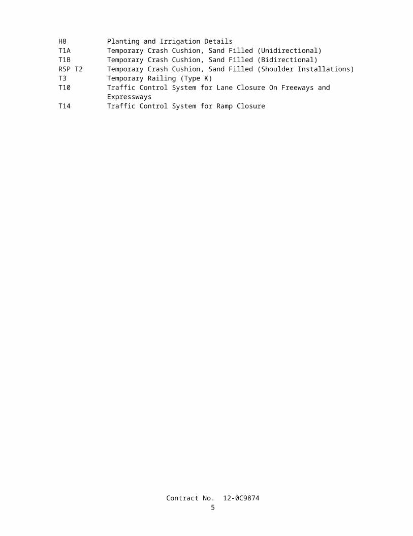
A10A AbbreviationsA10B SymbolsA62A Excavation and Backfill - Miscellaneous DetailsA62D Excavation and Backfill - Concrete Pipe CulvertsRSP A62DA Excavation and Backfill - Concrete Pipe CulvertsRSP A73C Delineators, Channelizers and BarricadesA87 Curbs, Dikes and DrivewaysD73 Drainage InletsD74A Drainage InletsD74B Drainage InletsD74C Drainage Inlet DetailsD77A Grate DetailsD78 Gutter DepressionsH1 Planting and Irrigation - AbbreviationsH2 Planting and Irrigation - SymbolsH5 Planting and Irrigation DetailsH6 Planting and Irrigation DetailsH8 Planting and Irrigation DetailsT1A Temporary Crash Cushion, Sand Filled (Unidirectional)T1B Temporary Crash Cushion, Sand Filled (Bidirectional)RSP T2 Temporary Crash Cushion, Sand Filled (Shoulder Installations)T3 Temporary Railing (Type K)T10 Traffic Control System for Lane Closure On Freeways and ExpresswaysT14 Traffic Control System for Ramp Closure
Contract No. 12-0C98744
Federal Project with DBE Goals (12-01-99)
DEPARTMENT OF TRANSPORTATION
_________________________
NOTICE TO CONTRACTORS_________________________
CONTRACT NO. 12-0C9874
12-Ora-73-20.9/34.6
Sealed proposals for the work shown on the plans entitled:
STATE OF CALIFORNIA; DEPARTMENT OF TRANSPORTATION; PROJECT PLANS FOR CONSTRUCTION ON STATE HIGHWAY IN AT VARIOUS LOCATIONS FROM MOULTON PARKWAY TO NEWPORT COAST
DRIVE
will be received at the Department of Transportation, 3347 Michelson Drive, Suite 100, Irvine, CA 92612-1692, until 2 o'clock p.m. on September 2, 2004, at which time they will be publicly opened and read in Room C - 1116 at the same address.
Proposal forms for this work are included in a separate book entitled:
STATE OF CALIFORNIA; DEPARTMENT OF TRANSPORTATION; PROPOSAL AND CONTRACT FOR CONSTRUCTION ON STATE HIGHWAY IN AT VARIOUS LOCATIONS FROM MOULTON PARKWAY TO
NEWPORT COAST DRIVE
General work description: Storm water drainage improvements.
This project has a goal of 8 percent disadvantaged business enterprise (DBE) participation.No prebid meeting is scheduled for this project.
THIS PROJECT IS SUBJECT TO THE "BUY AMERICA" PROVISIONS OF THE SURFACE TRANSPORTATION ASSISTANCE ACT OF 1982 AS AMENDED BY THE INTERMODAL SURFACE
TRANSPORTATION EFFICIENCY ACT OF 1991.
Bids are required for the entire work described herein.At the time this contract is awarded, the Contractor shall possess either a Class A license or one of the following Class C
licenses: C-12.This contract is subject to state contract nondiscrimination and compliance requirements pursuant to Government Code,
Section 12990.Inquiries or questions based on alleged patent ambiguity of the plans, specifications or estimate must be communicated
as a bidder inquiry prior to bid opening. Any such inquiries or questions, submitted after bid opening, will not be treated as a bid protest.
Contract No. 12-0C98741
Bidder inquiries may be made as follows:
The Department will consider bidder inquiries only when a completed "Bidder Inquiry" form is submitted. A copy of the "Bidder Inquiry" form is available at the Internet address shown below. The bidder inquiry shall include the bidder’s name and telephone number. Submit "Bidder Inquiry" forms to :
Construction Program Duty Senior3337 Michelson Dr., Ste. 380Irvine, CA 92612
Fax Number: (949) 724-2141Tel. Number: (949) 724-2159
To expedite processing, submittal of "Bidder Inquiry" forms via Fax is preferred.To the extent feasible and at the discretion of the Department, completed "Bidder Inquiry" forms submitted for
consideration will be investigated, and responses will be posted on the Internet at:
http://www.dot.ca.gov/hq/esc/oe/project_status/bid_inq.html
The responses to bidders' inquiries, unless incorporated into formal addenda to the contract, are not a part of the contract, and are provided for the bidder’s convenience only. In some instances, the question and answer may represent a summary of the matters discussed rather than a word-for-word recitation. The availability or use of information provided in the responses to bidders' inquiries is not to be construed in any way as a waiver of the provisions of Section 2-1.03 of the Standard Specifications or any other provision of the contract, the plans, Standard Specifications or Special Provisions, nor to excuse the contractor from full compliance with those contract requirements. Bidders are cautioned that subsequent responses or contract addenda may affect or vary a response previously given.
Project plans, special provisions, and proposal forms for bidding this project can only be obtained at the Department of Transportation, Plans and Bid Documents, Room 0200, MS #26, Transportation Building, 1120 N Street, Sacramento, California 95814, FAX No. (916) 654-7028, Telephone No. (916) 654-4490. Use FAX orders to expedite orders for project plans, special provisions and proposal forms. FAX orders must include credit card charge number, card expiration date and authorizing signature. Project plans, special provisions, and proposal forms may be seen at the above Department of Transportation office and at the offices of the District Directors of Transportation at Irvine, Oakland, and the district in which the work is situated. Standard Specifications and Standard Plans are available through the State of California, Department of Transportation, Publications Unit, 1900 Royal Oaks Drive, Sacramento, CA 95815, Telephone No. (916) 445-3520.
Cross sections for this project are not available.The successful bidder shall furnish a payment bond and a performance bond.The Department of Transportation hereby notifies all bidders that it will affirmatively ensure that in any contract entered
into pursuant to this advertisement, disadvantaged business enterprises will be afforded full opportunity to submit bids in response to this invitation.
The U.S. Department of Transportation (DOT) provides a toll-free "hotline" service to report bid rigging activities. Bid rigging activities can be reported Mondays through Fridays, between 8:00 a.m. and 5:00 p.m., eastern time, Telephone No. 1-800-424-9071. Anyone with knowledge of possible bid rigging, bidder collusion, or other fraudulent activities should use the "hotline" to report these activities. The "hotline" is part of the DOT's continuing effort to identify and investigate highway construction contract fraud and abuse and is operated under the direction of the DOT Inspector General. All information will be treated confidentially and caller anonymity will be respected.
Contract No. 12-0C98742

Pursuant to Section 1773 of the Labor Code, the general prevailing wage rates in the county, or counties, in which the work is to be done have been determined by the Director of the California Department of Industrial Relations. These wages are set forth in the General Prevailing Wage Rates for this project, available at the Labor Compliance Office at the offices of the District Director of Transportation for the district in which the work is situated, and available from the California Department of Industrial Relations’ internet web site at: http://www.dir.ca.gov. The Federal minimum wage rates for this project as predetermined by the United States Secretary of Labor are available through the California Department of Transportation's Electronic Project Document Distribution Site on the internet at http://hqidoc1.dot.ca.gov/. Addenda to modify the Federal minimum wage rates, if necessary, will be issued to holders of "Proposal and Contract" books. Future effective general prevailing wage rates which have been predetermined and are on file with the California Department of Industrial Relations are referenced but not printed in the general prevailing wage rates.
If there is a difference between the minimum wage rates predetermined by the United States Secretary of Labor and the general prevailing wage rates determined by the Director of the California Department of Industrial Relations for similar classifications of labor, the Contractor and subcontractors shall pay not less than the higher wage rate. The Department will not accept lower State wage rates not specifically included in the Federal minimum wage determinations. This includes "helper" (or other classifications based on hours of experience) or any other classification not appearing in the Federal wage determinations. Where Federal wage determinations do not contain the State wage rate determination otherwise available for use by the Contractor and subcontractors, the Contractor and subcontractors shall pay not less than the Federal minimum wage rate which most closely approximates the duties of the employees in question.
DEPARTMENT OF TRANSPORTATION
Deputy Director Transportation Engineering
Dated August 2, 2004
DJC
Contract No. 12-0C98743
COPY OF ENGINEER'S ESTIMATE
(NOT TO BE USED FOR BIDDING PURPOSES)
12-0C9874Item No.
Item Code Item Description Unit of Measure Estimated Quantity
1 074019 PREPARE STORM WATER POLLUTION PREVENTION PLAN
LS LUMP SUM
2 074020 WATER POLLUTION CONTROL LS LUMP SUM
3 074029 TEMPORARY SILT FENCE M 950
4 074031 TEMPORARY GRAVEL BAG BERM M 120
5 074032 TEMPORARY CONCRETE WASHOUT FACILITY EA 4
6 074033 TEMPORARY CONSTRUCTION ENTRANCE EA 5
7(S)
120090 CONSTRUCTION AREA SIGNS LS LUMP SUM
8(S)
120100 TRAFFIC CONTROL SYSTEM LS LUMP SUM
9(S)
120165 CHANNELIZER (SURFACE MOUNTED) EA 48
10 129000 TEMPORARY RAILING (TYPE K) M 450
11(S)
129100 TEMPORARY CRASH CUSHION MODULE EA 44
12 150206 ABANDON CULVERT M 140
13 150608 REMOVE CHAIN LINK FENCE M 250
14 150620 REMOVE GATE EA 5
15 150668 REMOVE FLARED END SECTION EA 8
16 033457 REMOVE COMPOST STORM WATER FILTER STRUCTURE
EA 4
17 033458 REMOVE COMPOST STORM WATER FILTER INLET EA 4
18 033459 REMOVE CORRUGATED METAL PIPE RISER EA 3
19 150806 REMOVE PIPE M 220
20 033460 REMOVE REINFORCED CONCRETE PIPE RISER EA 1
Contract No. 12-0C98744
Item No.
Item Code Item Description Unit of Measure Estimated Quantity
21 150820 REMOVE INLET EA 2
22 033461 REMOVE ROCK SLOPE PROTECTION M3 260
23 150859 REMOVE ASPHALT CONCRETE OVERSIDE DRAIN EA 2
24 152440 ADJUST MANHOLE TO GRADE EA 1
25 153239 REMOVE CONCRETE (CURB, GUTTER, AND SIDEWALK)
M2 30
26 160101 CLEARING AND GRUBBING LS LUMP SUM
27 190101 ROADWAY EXCAVATION M3 13 700
28(S)
203003 STRAW (EROSION CONTROL) TONN 7
29(S)
203014 FIBER (EROSION CONTROL) KG 1470
30(S)
203024 COMPOST (EROSION CONTROL) M3 360
31 203026 MOVE-IN/MOVE-OUT (EROSION CONTROL) EA 4
32(S)
203045 PURE LIVE SEED (EROSION CONTROL) KG 25
33(S)
203061 STABILIZING EMULSION (EROSION CONTROL) KG 240
34(S)
206401 MAINTAIN EXISTING IRRIGATION FACILITIES LS LUMP SUM
35(S)
208000 IRRIGATION SYSTEM LS LUMP SUM
36 250201 CLASS 2 AGGREGATE SUBBASE M3 19
37 260201 CLASS 2 AGGREGATE BASE M3 240
38 280000 LEAN CONCRETE BASE M3 20
39 390101 ASPHALT CONCRETE TONN 1
40 394002 PLACE ASPHALT CONCRETE (MISCELLANEOUS AREA)
M2 3
Contract No. 12-0C98745

Item No.
Item Code Item Description Unit of Measure Estimated Quantity
41 394040 PLACE ASPHALT CONCRETE DIKE (TYPE A) M 9
42(F)
510502 MINOR CONCRETE (MINOR STRUCTURE) M3 48.7
43 620909 450 MM ALTERNATIVE PIPE CULVERT M 40
44 620913 600 MM ALTERNATIVE PIPE CULVERT M 11
45 620924 900 MM ALTERNATIVE PIPE CULVERT M 8
46 033462 JACKED 600 MM REINFORCED CONCRETE PIPE M 50
47 703288 1200 MM CORRUGATED STEEL PIPE RISER (2.77 MM THICK)
M 10
48 719315 PRECAST CONCRETE PIPE MANHOLE M 2
49 731502 MINOR CONCRETE (MISCELLANEOUS CONSTRUCTION)
M3 40
50 731510 MINOR CONCRETE (CURB, GUTTER, SIDEWALK AND DRIVEWAY)
M3 5
51(S-F)
750001 MISCELLANEOUS IRON AND STEEL KG 1321
52(F)
033463 STAINLESS STEEL WIRE MESH M2 46
53 999990 MOBILIZATION LS LUMP SUM
Contract No. 12-0C98746
STATE OF CALIFORNIA
DEPARTMENT OF TRANSPORTATION
_____________________________
SPECIAL PROVISIONS
Annexed to Contract No. 12-0C9874
SECTION 1. SPECIFICATIONS AND PLANS
The work embraced herein shall conform to the provisions in the Standard Specifications dated July 1999, and the Standard Plans dated July 1999, of the Department of Transportation insofar as the same may apply, and these special provisions.
In case of conflict between the Standard Specifications and these special provisions, the special provisions shall take precedence over and shall be used in lieu of the conflicting portions.
AMENDMENTS TO JULY 1999 STANDARD SPECIFICATIONS
UPDATED March 25, 2004
Amendments to the Standard Specifications set forth in these special provisions shall be considered as part of the Standard Specifications for the purposes set forth in Section 5-1.04, "Coordination and Interpretation of Plans, Standard Specifications and Special Provisions," of the Standard Specifications. Whenever either the term "Standard Specifications is amended" or the term "Standard Specifications are amended" is used in the special provisions, the text or table following the term shall be considered an amendment to the Standard Specifications. In case of conflict between such amendments and the Standard Specifications, the amendments shall take precedence over and be used in lieu of the conflicting portions.
SECTION 2: PROPOSAL REQUIREMENTS AND CONDITIONS
Issue Date: June 19, 2003
Section 2-1.03, "Examination of Plans, Specifications, Contract, and Site of Work," of the Standard Specifications is amended to read:
2-1.03 Examination of Plans, Specifications, Contract, and Site of Work• The bidder shall examine carefully the site of the work contemplated, the plans and specifications, and the proposal
and contract forms therefor. The submission of a bid shall be conclusive evidence that the bidder has investigated and is satisfied as to the general and local conditions to be encountered, as to the character, quality and scope of work to be performed, the quantities of materials to be furnished and as to the requirements of the proposal, plans, specifications and the contract.
• The submission of a bid shall also be conclusive evidence that the bidder is satisfied as to the character, quality and quantity of surface and subsurface materials or obstacles to be encountered insofar as this information was reasonably ascertainable from an inspection of the site and the records of exploratory work done by the Department as shown in the bid documents, as well as from the plans and specifications made a part of the contract.
• Where the Department has made investigations of site conditions including subsurface conditions in areas where work is to be performed under the contract, or in other areas, some of which may constitute possible local material sources,
Contract No. 12-0C98747

bidders or contractors may, upon written request, inspect the records of the Department as to those investigations subject to and upon the conditions hereinafter set forth.
• Where there has been prior construction by the Department or other public agencies within the project limits, records of the prior construction that are currently in the possession of the Department and which have been used by, or are known to, the designers and administrators of the project will be made available for inspection by bidders or contractors, upon written request, subject to the conditions hereinafter set forth. The records may include, but are not limited to, as -built drawings, design calculations, foundation and site studies, project reports and other data assembled in connection with the investigation, design, construction and maintenance of the prior projects.
• Inspection of the records of investigations and project records may be made at the office of the district in which the work is situated, or in the case of records of investigations related to structure work, at the Transportation Laboratory in Sacramento, California.
• When a log of test borings or other record of geotechnical data obtained by the Department's investigation of surface and subsurface conditions is included with the contract plans, it is furnished for the bidders' or Contractor's information and its use shall be subject to the conditions and limitations set forth in this Section 2-1.03.
• In some instances, information considered by the Department to be of possible interest to bidders or contractors has been compiled as "Materials Information." The use of the "Materials Information" shall be subject to the conditions and limitations set forth in this Section 2-1.03 and Section 6-2, "Local Materials."
• When cross sections are not included with the plans, but are available, bidders or contractors may inspect the cross sections and obtain copies for their use, at their expense.
• When cross sections are included with the contract plans, it is expressly understood and agreed that the cross sections do not constitute part of the contract, do not necessarily represent actual site conditions or show location, character, dimensions and details of work to be performed, and are included in the plans only for the convenience of bidders and their use is subject to the conditions and limitations set forth in this Section 2-1.03.
• When contour maps were used in the design of the project, the bidders may inspect those maps, and if available, they may obtain copies for their use.
• The availability or use of information described in this Section 2-1.03 is not to be construed in any way as a waiver of the provisions of the first paragraph in this Section 2-1.03 and bidders and contractors are cautioned to make independent investigations and examinations as they deem necessary to be satisfied as to conditions to be encountered in the performance of the work and, with respect to possible local material sources, the quality and quantity of material available from the property and the type and extent of processing that may be required in order to produce material conforming to the requirements of the specifications.
• The Department assumes no responsibility for conclusions or interpretations made by a bidder or contractor based on the information or data made available by the Department. The Department does not assume responsibility for representation made by its officers or agents before the execution of the contract concerning surface or subsurface conditions, unless that representation is expressly stated in the contract.
• No conclusions or interpretations made by a bidder or contractor from the information and data made available by the Department will relieve a bidder or contractor from properly fulfilling the terms of the contract.
SECTION 5: CONTROL OF WORK
Issue Date: December 31, 2001
Section 5-1.02A, "Trench Excavation Safety Plans," of the Standard Specifications is amended to read:
5-1.02A Excavation Safety Plans• The Construction Safety Orders of the Division of Occupational Safety and Health shall apply to all excavations.
For all excavations 1.5 m or more in depth, the Contractor shall submit to the Engineer a detailed plan showing the design and details of the protective systems to be provided for worker protection from the hazard of caving ground during excavation. The detailed plan shall include any tabulated data and any design calculations used in the preparation of the plan. Excavation shall not begin until the detailed plan has been reviewed and approved by the Engineer.
• Detailed plans of protective systems for which the Construction Safety Orders require design by a registered professional engineer shall be prepared and signed by an engineer who is registered as a Civil Engineer in the State of California, and shall include the soil classification, soil properties, soil design calculations that demonstrate adequate stability of the protective system, and any other design calculations used in the preparation of the plan.
• No plan shall allow the use of a protective system less effective than that required by the Construction Safety Orders.
• If the detailed plan includes designs of protective systems developed only from the allowable configurations and slopes, or Appendices, contained in the Construction Safety Orders, the plan shall be submitted at least 5 days before the
Contract No. 12-0C98748

Contractor intends to begin excavation. If the detailed plan includes designs of protective systems developed from tabulated data, or designs for which design by a registered professional engineer is required, the plan shall be submitted at least 3 weeks before the Contractor intends to begin excavation.
• Attention is directed to Section 7-1.01E, "Trench Safety."
SECTION 9: MEASUREMENT AND PAYMENT
Issue Date: February 10, 2004
Section 9-1.04, "Notice of Potential Claim," of the Standard Specifications is amended to read:
9-1.04 NOTICE OF POTENTIAL CLAIM• It is the intention of this section that disputes between the parties arising under and by virtue of the contract be
brought to the attention of the Engineer at the earliest possible time in order that the matters may be resolved, if possible, or other appropriate action promptly taken.
• Disputes will not be considered unless the Contractor has first complied with specified notice or protest requirements, including Section 4-1.03, "Changes," Section 5-1.116, "Differing Site Conditions," Section 8-1.06, "Time of Completion," Section 8-1.07, "Liquidated Damages," and Section 8-1.10, "Utility and Non-Highway Facilities."
• For disputes arising under and by virtue of the contract, including an act or failure to act by the Engineer, the Contractor shall provide a signed written initial notice of potential claim to the Engineer within 5 days from the date the dispute first arose. The initial notice of potential claim shall provide the nature and circumstances involved in the dispute which shall remain consistent through the dispute. The initial notice of potential claim shall be submitted on Form CEM-6201A furnished by the Department and shall be certified with reference to the California False Claims Act, Government Code Sections 12650-12655. The Contractor shall assign an exclusive identification number for each dispute, determined by chronological sequencing, based on the date of the dispute.
• The exclusive identification number for each dispute shall be used on the following corresponding documents:
A. Initial notice of potential claim.B. Supplemental notice of potential claim.C. Full and final documentation of potential claim.D. Corresponding claim included in the Contractor's written statement of claims.
• The Contractor shall provide the Engineer the opportunity to examine the site of work within 5 days from the date of the initial notice of potential claim. The Contractor shall proceed with the performance of contract work unless otherwise specified or directed by the Engineer.
• Throughout the disputed work, the Contractor shall maintain records that provide a clear distinction between the incurred direct costs of disputed work and that of undisputed work. The Contractor shall allow the Engineer access to the Contractor's project records deemed necessary by the Engineer to evaluate the potential claim within 20 days of the date of the Engineer's written request.
• Within 15 days of submitting the initial notice of potential claim, the Contractor shall provide a signed supplemental notice of potential claim to the Engineer that provides the following information:
A. The complete nature and circumstances of the dispute which caused the potential claim.B. The contract provisions that provide the basis of claim.C. The estimated cost of the potential claim, including an itemized breakdown of individual costs and how the estimate
was determined.D. A time impact analysis of the project schedule that illustrates the effect on the scheduled completion date due to
schedule changes or disruptions where a request for adjustment of contract time is made.
• The information provided in items A and B above shall provide the Contractor's complete reasoning for additional compensation or adjustments.
• The supplemental notice of potential claim shall be submitted on Form CEM-6201B furnished by the Department and shall be certified with reference to the California False Claims Act, Government Code Sections 12650-12655. The Engineer will evaluate the information presented in the supplemental notice of potential claim and provide a written response to the Contractor within 20 days of its receipt. If the estimated cost or effect on the scheduled completion date changes, the Contractor shall update information in items C and D above as soon as the change is recognized and submit this information to the Engineer.
Contract No. 12-0C98749
• Within 30 days of the completion of work related to the potential claim, the Contractor shall provide the full and final documentation of potential claim to the Engineer that provides the following information:
A. A detailed factual narration of events fully describing the nature and circumstances that caused the dispute, including, but not limited to, necessary dates, locations, and items of work affected by the dispute.
B. The specific provisions of the contract that support the potential claim and a statement of the reasons these provisions support and provide a basis for entitlement of the potential claim.
C. When additional monetary compensation is requested, the exact amount requested calculated in conformance with Section 9-1.03, "Force Account Payment," or Section 8-1.09, "Right of Way Delays," including an itemized breakdown of individual costs. These costs shall be segregated into the following cost categories:
1. Labor – A listing of individuals, classifications, regular hours and overtime hours worked, dates worked, and other pertinent information related to the requested reimbursement of labor costs.
2. Materials – Invoices, purchase orders, location of materials either stored or incorporated into the work, dates materials were transported to the project or incorporated into the work, and other pertinent information related to the requested reimbursement of material costs.
3. Equipment – Listing of detailed description (make, model, and serial number), hours of use, dates of use and equipment rates. Equipment rates shall be at the applicable State rental rate as listed in the Department of Transportation publication entitled "Labor Surcharge and Equipment Rental Rates," in effect when the affected work related to the dispute was performed.
4. Other categories as specified by the Contractor or the Engineer.
D. When an adjustment of contract time is requested the following information shall be provided:
1. The specific dates for which contract time is being requested.2. The specific reasons for entitlement to a contract time adjustment.3. The specific provisions of the contract that provide the basis for the requested contract time adjustment.4. A detailed time impact analysis of the project schedule. The time impact analysis shall show the effect of
changes or disruptions on the scheduled completion date to demonstrate entitlement to a contract time adjustment.
E. The identification and copies of the Contractor's documents and the substance of oral communications that support the potential claim.
• The full and final documentation of the potential claim shall be submitted on Form CEM-6201C furnished by the Department and shall be certified with reference to the California False Claims Act, Government Code Sections 12650-12655.
• Pertinent information, references, arguments, and data to support the potential claim shall be included in the full and final documentation of potential claim. Information submitted subsequent to the full and final documentation submittal will not be considered. Information required in the full and final documentation of potential claim, as listed in items A to E above, that is not applicable to the dispute may be exempted as determined by the Engineer. No full and final documentation of potential claim will be considered that does not have the same nature and circumstances, and basis of claim as those specified on the initial and supplemental notices of potential claim.
• The Engineer will evaluate the information presented in the full and final documentation of potential claim and provide a written response to the Contractor within 30 days of its receipt unless otherwise specified. The Engineer's receipt of the full and final documentation of potential claim shall be evidenced by postal receipt or the Engineer's written receipt if delivered by hand. If the full and final documentation of potential claim is submitted by the Contractor after acceptance of the work by the Director, the Engineer need not provide a written response.
• Provisions in this section shall not apply to those claims for overhead costs and administrative disputes that occur after issuance of the proposed final estimate. Administrative disputes are disputes of administrative deductions or retentions, contract item quantities, contract item adjustments, interest payments, protests of contract change orders as provided in Section 4-1.03A, "Procedure and Protest," and protests of the weekly statement of working days as provided in Section 8-1.06, "Time of Completion." Administrative disputes that occur prior to issuance of the proposed final estimate shall follow applicable requirements of this section. Information listed in the supplemental notice and full and final documentation of potential claim that is not applicable to the administrative dispute may be exempted as determined by the Engineer.
• Unless otherwise specified in the special provisions, the Contractor may pursue the administrative claim process pursuant to Section 9-1.07B, "Final Payment and Claims," for any potential claim found by the Engineer to be without merit.
Contract No. 12-0C987410
• Failure of the Contractor to conform to specified dispute procedures shall constitute a failure to pursue diligently and exhaust the administrative procedures in the contract, and is deemed as the Contractor's waiver of the potential claim and a waiver of the right to a corresponding claim for the disputed work in the administrative claim process in conformance with Section 9-1.07B, "Final Payment of Claims," and shall operate as a bar to arbitration pursuant to Section 10240.2 of the California Public Contract Code.
Section 9-1.07B, "Final Payment and Claims," of the Standard Specifications is amended to read:
9-1.07B Final Payment and Claims• After acceptance by the Director, the Engineer will make a proposed final estimate in writing of the total amount
payable to the Contractor, including an itemization of the total amount, segregated by contract item quantities, extra work and other bases for payment, and shall also show each deduction made or to be made for prior payments and amounts to be kept or retained under the provisions of the contract. Prior estimates and payments shall be subject to correction in the proposed final estimate. The Contractor shall submit written approval of the proposed final estimate or a written statement of claims arising under or by virtue of the contract so that the Engineer receives the written approval or statement of claims no later than close of business of the thirtieth day after receiving the proposed final estimate. If the thirtieth day falls on a Saturday, Sunday or legal holiday, then receipt of the written approval or statement of claims by the Engineer shall not be later than close of business of the next business day. The Contractor's receipt of the proposed final estimate shall be evidenced by postal receipt. The Engineer's receipt of the Contractor's written approval or statement of claims shall be evidenced by postal receipt or the Engineer's written receipt if delivered by hand.
• On the Contractor's approval, or if the Contractor files no claim within the specified period of 30 days, the Engineer will issue a final estimate in writing in conformance with the proposed final estimate submitted to the Contractor, and within 30 days thereafter the State will pay the entire sum so found to be due. That final estimate and payment thereon shall be conclusive and binding against both parties to the contract on all questions relating to the amount of work done and the compensation payable therefor, except as otherwise provided in Sections 9-1.03C, "Records," and 9-1.09, "Clerical Errors."
• If the Contractor within the specified period of 30 days files claims, the Engineer will issue a semifinal estimate in conformance with the proposed final estimate submitted to the Contractor and within 30 days thereafter the State will pay the sum found to be due. The semifinal estimate and corresponding payment shall be conclusive and binding against both parties to the contract on each question relating to the amount of work done and the compensation payable therefor, except insofar as affected by the claims filed within the time and in the manner required hereunder and except as otherwise provided in Sections 9-1.03C, "Records," and 9-1.09, "Clerical Errors."
• Except for claims for overhead costs and administrative disputes that occur after issuance of the proposed final estimate, the Contractor shall only provide the following two items of information for each claim:
A. The exclusive identification number that corresponds to the supporting full and final documentation of potential claim.
B. The final amount of requested additional compensation.
• If the final amount of requested additional compensation is different than the amount of requested compensation included in the full and final documentation of potential claim, the Contractor shall provide in the written statement of claims the reasons for the changed amount, the specific provisions of the contract which support the changed amount, and a statement of the reasons the provisions support and provide a basis for the changed amount. If the Contractor's claim fails to provide an exclusive identification number or if there is a disparity in the provided exclusive identification number, the Engineer will notify the Contractor of the omission or disparity. The Contractor shall have 15 days after receiving notification from the Engineer to correct the omission or disparity. If after the 15 days has elapsed, there is still an omission or disparity of the exclusive identification number assigned to the claim, the Engineer will assign the number. No claim will be considered that has any of the following deficiencies:
A. The claim does not have the same nature, circumstances, and basis as the corresponding full and final documentation of potential claim.
B. The claim does not have a corresponding full and final documentation of potential claim.C. The claim was not included in the written statement of claims.D. The Contractor did not comply with applicable notice or protest requirements of Sections 4-1.03, "Changes,"
5-1.116, "Differing Site Condition," 8-1.06, "Time of Completion," 8-1.07, "Liquidated Damages," 8-1.10, "Utility and Non-Highway Facilities," and 9-1.04, "Notice of Potential Claim."
• Administrative disputes that occur after issuance of the proposed final estimate shall be included in the Contractor's written statement of claims in sufficient detail to enable the Engineer to ascertain the basis and amounts of those claims.
Contract No. 12-0C987411
• The Contractor shall keep full and complete records of the costs and additional time incurred for work for which a claim for additional compensation is made. The Engineer or designated claim investigators or auditors shall have access to those records and any other records as may be required by the Engineer to determine the facts or contentions involved in the claims. Failure to permit access to those records shall be sufficient cause for denying the claims.
• The written statement of claims submitted by the Contractor shall be accompanied by a notarized certificate containing the following language:
Under the penalty of law for perjury or falsification and with specific reference to the California False Claims Act, Government Code Section 12650 et. seq., the undersigned,
.(name)
of(title)
.(company)
hereby certifies that the claim for the additional compensation and time, if any, made herein for the work on this contract is a true statement of the actual costs incurred and time sought, and is fully documented and supported under the contract between parties.
Dated
/s/
Subscribed and sworn before me this day
of .
(Notary Public)My Commission Expires
• Failure to submit the notarized certificate will be sufficient cause for denying the claim.• Claims for overhead type expenses or costs, in addition to being certified as stated above, shall be supported and
accompanied by an audit report of an independent Certified Public Accountant. Omission of a supporting audit report of an independent Certified Public Accountant shall result in denial of the claim and shall operate as a bar to arbitration, as to the claim, in conformance with the requirements in Section 10240.2 of the California Public Contract Code. Claims for overhead type expenses or costs shall be subject to audit by the State at its discretion. The costs of performing an audit examination and submitting the report shall be borne by the Contractor. The Certified Public Accountant's audit examination shall be performed in conformance with the requirements of the American Institute of Certified Public Accountants Attestation Standards. The audit examination and report shall depict the Contractor's project and company-wide financial records and shall specify the actual overall average daily rates for both field and home office overhead for the entire duration of the project, and whether the costs have been properly allocated. The rates of field and home office overhead shall exclude unallowable costs as determined in Title 48 of the Federal Acquisition Regulations, Chapter 1, Part 31. The audit examination and report shall determine if the rates of field and home office overhead are:
A. Allowable in conformance with the requirements in Title 48 of the Federal Acquisition Regulations, Chapter 1, Part 31.
B. Adequately supported by reliable documentation.C. Related solely to the project under examination.
• Costs or expenses incurred by the State in reviewing or auditing claims that are not supported by the Contractor's cost accounting or other records shall be deemed to be damages incurred by the State within the meaning of the California False Claims Act.
• If the Contractor files a timely written statement of claims in response to the proposed final estimate, the District that administers the contract will submit a claim position letter to the Contractor by hand delivery or deposit in the U.S. mail within 135 days of acceptance of the contract. The claim position letter will delineate the District's position on the
Contract No. 12-0C987412

Contractor's claims. If the Contractor disagrees with the claim position letter, the Contractor shall submit a written notification of its disagreement and a written request to meet with the board of review, to be received by the District not later than 15 days after the Contractor's receipt of the claim position letter. The written notification of disagreement shall set forth the basis for the Contractor's disagreement and be submitted to the office designated in the claim position letter. The Contractor's failure to provide a timely written notification of disagreement or timely written request to meet with the board of review shall constitute the Contractor's acceptance and agreement with the determinations provided in the claim position letter and with final payment pursuant to the claim position letter.
• If the Contractor files a timely notification of disagreement with the District claim position letter and a timely request to meet with the board of review, then the board of review, designated by the District Director to review claims that remain in dispute, will meet with the Contractor within 45 days after receipt by the District of the notification of disagreement.
• If the District fails to submit a claim position letter to the Contractor within 135 days after the acceptance of the contract and the Contractor has claims that remain in dispute, the Contractor may request a meeting with the board of review designated by the District Director to review claims that remain in dispute. The Contractor's request for a meeting shall identify the claims that remain in dispute. If the Contractor files a request for a meeting, the board of review will meet with the Contractor within 45 days after the District receives the request for the meeting.
• Attendance by the Contractor at the board of review meeting shall be mandatory. The board of review will review those claims and make a written recommendation thereon to the District Director. The final determination of claims, made by the District Director, will be sent to the Contractor by hand delivery or deposit in the U.S. mail. The Engineer will then make and issue the Engineer's final estimate in writing and within 30 days thereafter the State will pay the entire sum, if any, found due thereon. That final estimate shall be conclusive and binding against both parties to the contract on all questions relating to the amount of work done and the compensation payable therefor, except as otherwise provided in Sections 9-1.03C, "Records," and 9-1.09, "Clerical Errors."
• Failure of the Contractor to conform to the specified dispute procedures shall constitute a failure to pursue diligently and exhaust the administrative procedures in the contract and shall operate as a bar to arbitration in conformance with the requirements in Section 10240.2 of the California Public Contract Code.
SECTION 19: EARTHWORK
Issue Date: December 31, 2001
The third paragraph of Section 19-1.02, "Preservation of Property," of the Standard Specifications is amended to read:
• In addition to the provisions in Sections 5-1.02, "Plans and Working Drawings," and 5-1.02A, "Excavation Safety Plans," detailed plans of the protective systems for excavations on or affecting railroad property will be reviewed for adequacy of protection provided for railroad facilities, property, and traffic. These plans shall be submitted at least 9 weeks before the Contractor intends to begin excavation requiring the protective systems. Approval by the Engineer of the detailed plans for the protective systems will be contingent upon the plans being satisfactory to the railroad company involved.
SECTION 42: GROOVE AND GRIND PAVEMENT
Issue Date: December 31, 2001
The last sentence of the first subparagraph of the third paragraph in Section 42-2.02, "Construction," of the Standard Specifications is amended to read:
• After grinding has been completed, the pavement shall conform to the straightedge and profile requirements specified in Section 40-1.10, "Final Finishing."
SECTION 49: PILING
Issue Date: March 25, 2004
The first paragraph in Section 49-1.03, "Determination of Length," of the Standard Specifications is amended to read:
• Foundation piles of any material shall be of such length as is required to develop the nominal resistance, to obtain the specified penetration, and to extend into the cap or footing block as shown on the plans, or specified in the special provisions.
Contract No. 12-0C987413
The fourth paragraph in Section 49-1.03, "Determination of Length," of the Standard Specifications is amended to read:
• Modification to the specified installation methods and specified pile tip elevation will not be considered at locations where tension or lateral load demands control design pile tip elevations or when the plans state that specified pile tip elevation shall not be revised.
The sixth and seventh paragraphs in Section 49-1.03, "Determination of Length," of the Standard Specifications are amended to read:
• Indicator compression pile load testing shall conform to the requirements in ASTM Designation: D 1143. The pile shall sustain the first compression test load applied which is equal to the nominal resistance in compression, as shown on the plans, with no more than 13 mm total vertical movement at the top of the pile measured relative to the top of the pile prior to the start of compression load testing.
• Indicator tension pile load testing shall conform to the requirements in ASTM Designation: D 3689. The loading apparatus described as "Load Applied to Pile by Hydraulic Jack(s) Acting at One End of Test Beam(s) Anchored to the Pile" shall not be used. The pile shall sustain the first tension test load applied which is equal to the nominal resistance in tension, as shown on the plans, with no more than 13 mm total vertical movement at the top of the pile measured relative to the top of the pile prior to the start of tension load testing.
The ninth paragraph in Section 49-1.03, "Determination of Length," of the Standard Specifications is amended to read:
• For driven piling, the Contractor shall furnish piling of sufficient length to obtain both the specified tip elevation and nominal resistance shown on the plans or specified in the special provisions. For cast -in-drilled-hole concrete piling, the Contractor shall construct piling of such length to develop the nominal resistance in compression and to obtain the specified tip elevation shown on the plans or specified in the special provisions.
The tenth paragraph in Section 49-1.03, "Determination of Length," of the Standard Specifications is deleted.
The fourth paragraph in Section 49-1.04, "Load Test Piles," of the Standard Specifications is amended to read:
• Load test piles and anchor piles which are not to be incorporated in the completed structure shall be removed in conformance with the provisions in Section 15-4.02, "Removal Methods," and the remaining holes shall be backfilled with earth or other suitable material approved by the Engineer.
The first paragraph in Section 49-1.05, "Driving Equipment," of the Standard Specifications is amended to read:
• Driven piles shall be installed with impact hammers that are approved in writing by the Engineer. Impact hammers shall be steam, hydraulic, air or diesel hammers. Impact hammers shall develop sufficient energy to drive the piles at a penetration rate of not less than 3 mm per blow at the specified nominal resistance.
The seventh paragraph in Section 49-1.05, "Driving Equipment," of the Standard Specifications is amended to read:
• When necessary to obtain the specified penetration and when authorized by the Engineer, the Contractor may supply and operate one or more water jets and pumps, or furnish the necessary drilling apparatus and drill holes not greater than the least dimension of the pile to the proper depth and drive the piles therein. Jets shall not be used at locations where the stability of embankments or other improvements would be endangered. In addition, for steel piles, steel shells, or steel casings, when necessary to obtain the specified penetration or to prevent damage to the pile during installation, the Contractor shall provide special driving tips or heavier pile sections or take other measures as approved by the Engineer.
• The use of followers or underwater hammers for driving piles will be permitted if authorized in writing by the Engineer. When a follower or underwater hammer is used, its efficiency shall be verified by furnishing the first pile in each bent or footing sufficiently long and driving the pile without the use of a follower or underwater hammer.
The second paragraph in Section 49-1.07, "Driving," of the Standard Specifications is amended to read:
• Timber piles shall be fresh-headed and square and when permitted by the Engineer, the heads of the piles may be protected by means of heavy steel or wrought iron rings. During driving operations timber piling shall be restrained from
Contract No. 12-0C987414
lateral movement at intervals not to exceed 6 m over the length between the driving head and the ground surface. During driving operations, the timber pile shall be kept moving by continuous operation of the hammer. When the blow count exceeds either 2 times the blow count required in 300 mm, or 3 times the blow count required in 75 mm for the nominal resistance as shown on the plans, computed in conformance with the provisions in Section 49-1.08, "Pile Driving Acceptance Criteria," additional aids shall be used to obtain the specified penetration. These aids may include the use of water jets or drilling, where permitted, or the use of a larger hammer employing a heavy ram striking with a low velocity.
Section 49-1.08, "Bearing Value and Penetration," of the Standard Specifications is amended to read:
49-1.08 PILE DRIVING ACCEPTANCE CRITERIA• Except for piles to be load tested, driven piles shall be driven to a value of not less than the nominal resistance
shown on the plans unless otherwise specified in the special provisions or permitted in writing by the Engineer. In addition, when a pile tip elevation is specified, driven piles shall penetrate at least to the specified tip elevation, unless otherwise permitted in writing by the Engineer. Piles to be load tested shall be driven to the specified tip elevation.
• When the pile nominal resistance is omitted from the plans or the special provisions, timber piles shall be driven to a nominal resistance of 800 kN, and steel and concrete piles shall be driven to a nominal resistance of 1250 kN.
• The nominal resistance for driven piles shall be determined from the following formula in which "Ru" is the nominal resistance in kilonewtons, "Er" is the manufacturer's rating for joules of energy developed by the hammer at the observed field drop height, and "N" is the number of hammer blows in the last 300 millimeters. (maximum value to be used for N is 100):
Ru = (7 * (Er)1/2*log10 (0.83 * N)) - 550
Section 49-3.01, "Description," of the Standard Specifications is amended by deleting the fifth paragraph.
The sixth paragraph in Section 49-3.01, "Description," of the Standard Specifications is amended to read:
• Lifting anchors used in precast prestressed concrete piles without a class designation ending in "C" (corrosion resistant) shall be removed, and the holes filled in conformance with the provisions in Section 51-1.18A, "Ordinary Surface Finish."
The first and second paragraphs in Section 49-4.01, "Description," of the Standard Specifications are amended to read:
• Cast-in-place concrete piles shall consist of one of the following:
A. Steel shells driven permanently to the required nominal resistance and penetration and filled with concrete.B. Steel casings installed permanently to the required penetration and filled with concrete.C. Drilled holes filled with concrete.D. Rock sockets filled with concrete.
• The drilling of holes shall conform to the provisions in these specifications. Concrete filling for cast-in-place concrete piles is designated by compressive strength and shall have a minimum 28-day compressive strength of 25 MPa. At the option of the Contractor, the combined aggregate grading for the concrete shall be either the 25-mm maximum grading, the 12.5-mm maximum grading, or the 9.5-mm maximum grading. Concrete shall conform to the provisions in Section 90, "Portland Cement Concrete," and Section 51, "Concrete Structures." Reinforcement shall conform to the provisions in Section 52, "Reinforcement."
The fourth paragraph in Section 49-4.03, "Drilled Holes," of the Standard Specifications is amended to read:
• After placing reinforcement and prior to placing concrete in the drilled hole, if caving occurs or deteriorated foundation material accumulates on the bottom of the hole, the bottom of the drilled hole shall be cleaned. The Contractor shall verify that the bottom of the drilled hole is clean.
The first and second paragraphs in Section 49-4.04, "Steel Shells," of the Standard Specifications are amended to read:
• Steel shells shall be sufficiently watertight to exclude water during the placing of concrete. The shells may be cylindrical or tapered, step-tapered, or a combination of either, with cylindrical sections.
Contract No. 12-0C987415
The first paragraph in Section 49-4.05, "Inspection," of the Standard Specifications is amended to read:
• After being driven and prior to placing reinforcement and concrete therein, the steel shells shall be examined for collapse or reduced diameter at any point. Any shell which is improperly driven or broken or shows partial collapse to such an extent as to materially decrease its nominal resistance will be rejected. Rejected shells shall be removed and replaced, or a new shell shall be driven adjacent to the rejected shell. Rejected shells which cannot be removed shall be filled with concrete by the Contractor at the Contractor's expense. When a new shell is driven to replace a rejected shell, the Contractor, at the Contractor's expense, shall enlarge the footing as determined necessary by the Engineer.
The third paragraph in Section 49-5.01, "Description," of the Standard Specifications is amended to read:
• Steel pipe piles shall conform to the following requirements:
1. Steel pipe piles less than 360 mm in diameter shall conform to the requirements in ASTM Designation: A 252, Grade 2 or 3.
2. Steel pipe piles 360 mm and greater in diameter shall conform to the requirements in ASTM Designation: A 252, Grade 3.
3. Steel pipe piles shall be of the nominal diameter and nominal wall thickness shown on the plans or specified in the special provisions.
4. The carbon equivalency (CE) of steel for steel pipe piles, as defined in AWS D 1.1, Section XI5.1, shall not exceed 0.45.
5. The sulfur content of steel for steel pipe piles shall not exceed 0.05-percent.6. Seams in steel pipe piles shall be complete penetration welds.
The third paragraph in Section 49-6.02, "Payment," of the Standard Specifications is amended to read:
• The contract price paid per meter for cast-in-drilled-hole concrete piling shall include full compensation for furnishing all labor, materials, tools, equipment, and incidentals, and for doing all work involved in drilling holes, disposing of material resulting from drilling holes, temporarily casing holes and removing water when necessary, furnishing and placing concrete and reinforcement, and constructing reinforced concrete extensions, complete in place, to the required penetration, as shown on the plans, as specified in these specifications and in the special provisions, and as directed by the Engineer.
The seventh paragraph in Section 49-6.02, "Payment," of the Standard Specifications is amended to read
• The contract unit price paid for drive pile shall include full compensation for furnishing all labor, materials, tools, equipment, and incidentals, and for doing all the work involved in driving timber, concrete and steel piles, driving steel shells for cast-in-place concrete piles, placing filling materials for cast-in-place concrete piles and cutting off piles, all complete in place to the required nominal resistance and penetration as shown on the plans and as specified in these specifications and the special provisions, and as directed by the Engineer.
The ninth paragraph in Section 49-6.02, "Payment," of the Standard Specifications is amended to read:
• Full compensation for all jetting, drilling, providing special driving tips or heavier sections for steel piles or shells, or other work necessary to obtain the specified penetration and nominal resistance of the piles, for predrilling holes through embankment and filling the space remaining around the pile with sand or pea gravel, for disposing of material resulting from jetting, drilling or predrilling holes, and for all excavation and backfill involved in constructing concrete extensions as shown on the plans, and as specified in these specifications and the special provisions, and as directed by the Engineer shall be considered as included in the contract unit price paid for drive pile or in the contract price paid per meter for cast-in-drilled-hole concrete piling, and no additional compensation will be allowed therefor.
Section 49-6.02, "Payment," of the Standard Specifications is amended by adding the following paragraphs:
Full compensation for furnishing and placing additional testing reinforcement, for load test anchorages, and for cutting off test piles, shall be considered as included in the contract price paid for piling of the type or class shown in the Engineer's Estimate, and no additional compensation will be allowed.
Contract No. 12-0C987416
No additional compensation or extension of time will be made for additional foundation investigation, installation and testing of indicator piling, cutting off piling and restoring the foundation investigation and indicator pile sites, and review of request by the Engineer
SECTION 50: PRESTRESSING CONCRETE
Issue Date: November 18, 2002
Section 50-1.02, "Drawings," of the Standard Specifications is amended by adding the following paragraph after the second paragraph:
• Each working drawing submittal shall consist of plans for a single bridge or portion thereof. For multi-frame bridges, each frame shall require a separate working drawing submittal.
Section 50-1.05, "Prestressing Steel," of the Standard Specifications is amended to read:
• Prestressing steel shall be high-tensile wire conforming to the requirements in ASTM Designation: A 421, including Supplement I; high-tensile seven-wire strand conforming to the requirements in ASTM Designation: A 416; or uncoated high-strength steel bars conforming to the requirements in ASTM Designation: A 722, including all supplementary requirements. The maximum mass requirement of ASTM Designation: A 722 will not apply.
• In addition to the requirements of ASTM Designation: A 722, for deformed bars, the reduction of area shall be determined from a bar from which the deformations have been removed. The bar shall be machined no more than necessary to remove the deformations over a length of 300 mm, and reduction will be based on the area of the machined portion.
• In addition to the requirements specified herein, epoxy-coated seven-wire prestressing steel strand shall be grit impregnated and filled in conformance with the requirements in ASTM Designation: A 882/A 882M, including Supplement I, and the following:
A. The coating material shall be on the Department's list of approved coating materials for epoxy-coated strand, available from the Transportation Laboratory.
B. The film thickness of the coating after curing shall be 381 µm to 1143 µm.C. Prior to coating the strand, the Contractor shall furnish to the Transportation Laboratory a representative 230-g
sample from each batch of epoxy coating material to be used. Each sample shall be packaged in an airtight container identified with the manufacturer's name and batch number.
D. Prior to use of the epoxy-coated strand in the work, written certifications referenced in ASTM Designation: A 882/A 882M, including a representative load-elongation curve for each size and grade of strand to be used and a copy of the quality control tests performed by the manufacturer, shall be furnished to the Engineer.
E. In addition to the requirements in Section 50-1.10, "Samples for Testing," four 1.5-m long samples of coated strand and one 1.5-m long sample of uncoated strand of each size and reel shall be furnished to the Engineer for testing. These samples, as selected by the Engineer, shall be representative of the material to be used in the work.
F. Epoxy-coated strand shall be cut using an abrasive saw.G. All visible damage to coatings caused by shipping and handling, or during installation, including cut ends, shall be
repaired in conformance with the requirements in ASTM Designation: A 882/A 882M. The patching material shall be furnished by the manufacturer of the epoxy powder and shall be applied in conformance with the manufacturer's written recommendations. The patching material shall be compatible with the original epoxy coating material and shall be inert in concrete.
• All bars in any individual member shall be of the same grade, unless otherwise permitted by the Engineer.• When bars are to be extended by the use of couplers, the assembled units shall have a tensile strength of not less
than the manufacturer's minimum guaranteed ultimate tensile strength of the bars. Failure of any one sample to meet this requirement will be cause for rejection of the heat of bars and lot of couplers. The location of couplers in the member shall be subject to approval by the Engineer.
• Wires shall be straightened if necessary to produce equal stress in all wires or wire groups or parallel lay cables that are to be stressed simultaneously or when necessary to ensure proper positioning in the ducts.
• Where wires are to be button-headed, the buttons shall be cold formed symmetrically about the axes of the wires. The buttons shall develop the minimum guaranteed ultimate tensile strength of the wire. No cold forming process shall be used that causes indentations in the wire. Buttonheads shall not contain wide open splits, more than 2 splits per head, or splits not parallel with the axis of the wire.
Contract No. 12-0C987417
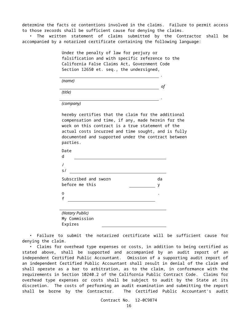
• Prestressing steel shall be protected against physical damage and rust or other results of corrosion at all times from manufacture to grouting or encasing in concrete. Prestressing steel that has sustained physical damage at any time shall be rejected. The development of visible rust or other results of corrosion shall be cause for rejection, when ordered by the Engineer.
• Epoxy-coated prestressing steel strand shall be covered with an opaque polyethylene sheeting or other suitable protective material to protect the strand from exposure to sunlight, salt spray, and weather. For stacked coils, the protective covering shall be draped around the perimeter of the stack. The covering shall be adequately secured; however, it should allow for air circulation around the strand to prevent condensation under the covering. Epoxy-coated strand shall not be stored within 300 m of ocean or tidal water for more than 2 months.
• Prestressing steel shall be packaged in containers or shipping forms for the protection of the steel against physical damage and corrosion during shipping and storage. Except for epoxy-coated strand, a corrosion inhibitor which prevents rust or other results of corrosion, shall be placed in the package or form, or shall be incorporated in a corrosion inhibitor carrier type packaging material, or when permitted by the Engineer, may be applied directly to the steel. The corrosion inhibitor shall have no deleterious effect on the steel or concrete or bond strength of steel to concrete. Packaging or forms damaged from any cause shall be immediately replaced or restored to original condition.
• The shipping package or form shall be clearly marked with a statement that the package contains high-strength prestressing steel, and the type of corrosion inhibitor used, including the date packaged.
• Prestressing steel for post-tensioning which is installed in members prior to placing and curing of the concrete, and which is not epoxy-coated, shall be continuously protected against rust or other results of corrosion, until grouted, by means of a corrosion inhibitor placed in the ducts or applied to the steel in the duct. The corrosion inhibitor shall conform to the provisions specified herein.
• When steam curing is used, prestressing steel for post-tensioning shall not be installed until the steam curing is completed.
• Water used for flushing ducts shall contain either quick lime (calcium oxide) or slaked lime (calcium hydroxide) in the amount of 0.01-kg/L. Compressed air used to blow out ducts shall be oil free.
• When prestressing steel for post-tensioning is installed in the ducts after completion of concrete curing, and if stressing and grouting are completed within 10 days after the installation of the prestressing steel, rust which may form during those 10 days will not be cause for rejection of the steel. Prestressing steel installed, tensioned, and grouted in this manner, all within 10 days, will not require the use of a corrosion inhibitor in the duct following installation of the prestressing steel. Prestressing steel installed as above but not grouted within 10 days shall be subject to all the requirements in this section pertaining to corrosion protection and rejection because of rust. The requirements in this section pertaining to tensioning and grouting within 10 days shall not apply to epoxy-coated prestressing steel strand.
• Any time prestressing steel for pretensioning is placed in the stressing bed and is exposed to the elements for more than 36 hours prior to encasement in concrete, adequate measures shall be taken by the Contractor, as approved by the Engineer, to protect the steel from contamination or corrosion.
• After final fabrication of the seven-wire prestressing steel strand, no electric welding of any form shall be performed on the prestressing steel. Whenever electric welding is performed on or near members containing prestressing steel, the welding ground shall be attached directly to the steel being welded.
• Pretensioned prestressing steel shall be cut off flush with the end of the member. For epoxy-coated prestressing steel, only abrasive saws shall be used to cut the steel. The exposed ends of the prestressing steel and a 25 -mm strip of adjoining concrete shall be cleaned and painted. Cleaning shall be by wire brushing or abrasive blast cleaning to remove all dirt and residue on the metal or concrete surfaces. Immediately after cleaning, the surfaces shall be covered with one application of unthinned zinc-rich primer (organic vehicle type) conforming to the provisions in Section 91, "Paint," except that 2 applications shall be applied to surfaces which will not be covered by concrete or mortar. Aerosol cans shall not be used. The paint shall be thoroughly mixed at the time of application and shall be worked into any voids in the prestressing tendons.
The thirteenth paragraph in Section 50-1.08, "Prestressing," of the Standard Specifications is amended to read:
• Prestressing steel in pretensioned members shall not be cut or released until the concrete in the member has attained a compressive strength of not less than the value shown on the plans or 28 MPa, whichever is greater. In addition to these concrete strength requirements, when epoxy-coated prestressing steel strand is used, the steel shall not be cut or released until the temperature of the concrete surrounding the strand is less than 65C, and falling.
The fifth paragraph in Section 50-1.10, "Samples for Testing," of the Standard Specifications is amended to read:
• The following samples of materials and tendons, selected by the Engineer from the prestressing steel at the plant or jobsite, shall be furnished by the Contractor to the Engineer well in advance of anticipated use:
Contract No. 12-0C987418
A. For wire or bars, one 2-m long sample and for strand, one 1.5-m long sample, of each size shall be furnished for each heat or reel.
B. For epoxy-coated strand, one 1.5-m long sample of uncoated strand of each size shall be furnished for each reel.C. If the prestressing tendon is a bar, one 2-m long sample shall be furnished and in addition, if couplers are to be used
with the bar, two 1.25-m long samples of bar, equipped with one coupler and fabricated to fit the coupler, shall be furnished.
The second paragraph in Section 50-1.11, "Payment," of the Standard Specifications is amended to read:
• The contract lump sum prices paid for prestressing cast-in-place concrete of the types listed in the Engineer's Estimate shall include full compensation for furnishing all labor, materials, tools, equipment, and incidentals, and for doing all work involved in furnishing, placing, and tensioning the prestressing steel in cast-in-place concrete structures, complete in place, as shown on the plans, as specified in these specifications and the special provisions, and as directed by the Engineer.
SECTION 51: CONCRETE STRUCTURES
Issue Date: December 23, 2003
The eleventh paragraph in Section 51-1.05, "Forms," of the Standard Specifications is amended to read:
• Form panels for exposed surfaces shall be furnished and placed in uniform widths of not less than 0.9 -m and in uniform lengths of not less than 1.8 m, except at the end of continuously formed surfaces where the final panel length required is less than 1.8 m. Where the width of the member formed is less than 0.9-m, the width of the panels shall be not less than the width of the member. Panels shall be arranged in symmetrical patterns conforming to the general lines of the structure. Except when otherwise provided herein or shown on the plans, panels for vertical surfaces shall be placed with the long dimension horizontal and with horizontal joints level and continuous. Form panels for curved surfaces of columns shall be continuous for a minimum of one quarter of the circumference, or 1.8 m. For walls with sloping footings which do not abut other walls, panels may be placed with the long dimension parallel to the footing. Form panels on each side of the panel joint shall be precisely aligned, by means of supports or fasteners common to both panels, to result in a continuous unbroken concrete plane surface. When prefabricated soffit panels are used, form filler panels joining prefabricated panels shall have a uniform minimum width of 0.3-m and shall produce a smooth uniform surface with consistent longitudinal joint lines between the prefabricated panels.
The first and second paragraph in Section 51-1.06A, "Falsework Design and Drawings," of the Standard Specifications are amended to read:
• The Contractor shall submit to the Engineer working drawings and design calculations for falsework proposed for use at bridges. For bridges where the height of any portion of the falsework, as measured from the ground line to the soffit of the superstructure, exceeds 4.25 m; or where any individual falsework clear span length exceeds 4.85 m; or where provision for vehicular, pedestrian, or railroad traffic through the falsework is made; the drawings shall be signed by an engineer who is registered as a Civil Engineer in the State of California. Six sets of the working drawings and 2 copies of the design calculations shall be furnished. Additional working drawings and design calculations shall be submitted to the Engineer when specified in "Railroad Relations and Insurance" of the special provisions.
• The falsework drawings shall include details of the falsework erection and removal operations showing the methods and sequences of erection and removal and the equipment to be used. The details of the falsework erection and removal operations shall demonstrate the stability of all or any portions of the falsework during all stages of the erection and removal operations.
The seventh paragraph in Section 51-1.06A, "Falsework Design and Drawings," of the Standard Specifications is amended to read:
• In the event that several falsework plans are submitted simultaneously, or an additional plan is submitted for review before the review of a previously submitted plan has been completed, the Contractor shall designate the sequence in which the plans are to be reviewed. In such event, the time to be provided for the review of any plan in the sequence shall be not less than the review time specified above for that plan, plus 2 weeks for each plan of higher priority which is still under review. A falsework plan submittal shall consist of plans for a single bridge or portion thereof. For multi-frame bridges, each frame shall require a separate falsework plan submittal.
Contract No. 12-0C987419
Section 51-1.06A, "Falsework Design and Drawings," of the Standard Specifications is amended by adding the following paragraphs:
• If structural composite lumber is proposed for use, the falsework drawings shall clearly identify the structural composite lumber members by grade (E value), species, and type. The Contractor shall provide technical data from the manufacturer showing the tabulated working stress values of the composite lumber. The Contractor shall furnish a certificate of compliance as specified in Section 6-1.07, "Certificates of Compliance," for each delivery of structural composite lumber to the project site.
• For falsework piles with a calculated loading capacity greater than 900 kN, the falsework piles shall be designed by an engineer who is registered as either a Civil Engineer or a Geotechnical Engineer in the State of California, and the calculations shall be submitted to the Engineer.
The first paragraph in Section 51-1.06A(1), "Design Loads," of the Standard Specifications is amended to read:
• The design load for falsework shall consist of the sum of dead and live vertical loads, and an assumed horizontal load. The minimum total design load for any falsework, including members that support walkways, shall be not less than 4800 N/m2 for the combined live and dead load regardless of slab thickness.
The eighth paragraph in Section 51-1.06A(1), "Design Loads," of the Standard Specifications is amended to read:
• In addition to the minimum requirements specified in this Section 51-1.06A, falsework for box girder structures with internal falsework bracing systems using flexible members capable of withstanding tensile forces only, shall be designed to include the vertical effects caused by the elongation of the flexible member and the design horizontal load combined with the dead and live loads imposed by concrete placement for the girder stems and connected bottom slabs. Falsework comprised of individual steel towers with bracing systems using flexible members capable of withstanding tensile forces only to resist overturning, shall be exempt from these additional requirements.
The third paragraph in Section 51-1.06B, "Falsework Construction," of the Standard Specifications is amended to read:
• When falsework is supported on piles, the piles shall be driven and the actual nominal resistance assessed in conformance with the provisions in Section 49, "Piling."
Section 51-1.06B, "Falsework Construction," of the Standard Specifications is amended by adding the following paragraphs:
• For falsework piles with a calculated nominal resistance greater than 1800 kN, the Contractor shall conduct dynamic monitoring of pile driving and generate field acceptance criteria based on a wave equation analysis. These analyses shall be signed by an engineer who is registered as a Civil Engineer in the State of California and submitted to the Engineer prior to completion of falsework erection.
• Prior to the placement of falsework members above the stringers, the final bracing system for the falsework shall be installed.
Section 51-1.06C, "Removing Falsework," of the Standard Specifications is amended by adding the following paragraph:
• The falsework removal operation shall be conducted in such a manner that any portion of the falsework not yet removed remains in a stable condition at all times.
The sixth paragraph in Section 51-1.09, "Placing Concrete," of the Standard Specifications is amended to read:
• Vibrators used to consolidate concrete containing epoxy-coated bar reinforcement or epoxy-coated prestressing steel shall have a resilient covering to prevent damage to the epoxy-coating on the reinforcement or prestressing steel.
The third sentence of the fourth paragraph in Section 51-1.12D, "Sheet Packing, Preformed Pads and Board Fillers," of the Standard Specifications is amended to read:
Surfaces of expanded polystyrene against which concrete is placed shall be faced with hardboard.
Contract No. 12-0C987420
The table in the ninth paragraph of Section 51-1.12H(1), "Plain and Fabric Reinforced Elastomeric Bearing Pads," of the Standard Specifications is amended to read:
Tensile strength, percent -15Elongation at break, percent -40; but not less than 300% total
elongation of the materialHardness, points +10
The first sentence of the fourth paragraph in Section 51-1.17, "Finish Bridge Decks," of the Standard Specifications is amended to read:
• The smoothness of completed roadway surfaces of structures, approach slabs and the adjacent 15 m of approach pavement, and the top surfaces of concrete decks which are to be covered with another material, will be tested by the Engineer with a bridge profilograph in conformance with the requirements in California Test 547 and the requirements herein.
Section 51-1.17, "Finishing Bridge Decks," of the Standard Specifications is amended by deleting the seventh, thirteenth and fourteenth paragraphs.
The fourteenth paragraph in Section 51-1.23, "Payment," of the Standard Specifications is amended by deleting "and injecting epoxy in cracks".
SECTION 52: REINFORCEMENT
Issue Date: March 25, 2004
The third paragraph in Section 52-1.04, "Inspection," of the Standard Specifications is amended to read:
• A Certificate of Compliance conforming to the provisions in Section 6-1.07, "Certificates of Compliance," shall also be furnished for each shipment of epoxy-coated bar reinforcement or wire reinforcement certifying that the coated reinforcement conforms to the requirements in ASTM Designation: A 775/A 775M or A 884/A 884M, respectively, and the provisions in Section 52-1.02B, "Epoxy-coated Reinforcement." The Certificate of Compliance shall include all of the certifications specified in ASTM Designation: A 775/A 775M or A 884/A 884M respectively, and a statement that the coating material has been prequalified by acceptance testing performed by the Valley Forge Laboratories, Inc., Devon, Pennsylvania.
Section 52-1.07 "Placing," of the Standard Specifications is amended to read by deleting item C of the third paragraph.
Section 52-1.08 "Splicing," of the Standard Specifications is amended to read:
52-1.08 SPLICING• Splices of reinforcing bars shall consist of lap splices, service splices, or ultimate butt splices.• Splicing of reinforcing bars will not be permitted at a location designated on the plans as a "No-Splice Zone." At
the option of the Contractor, reinforcing bars may be continuous at locations where splices are shown on the plans. The location of splices, except where shown on the plans, shall be determined by the Contractor using available commercial lengths where practicable.
• Unless otherwise shown on the plans, splices in adjacent reinforcing bars at any particular section shall be staggered. The minimum distance between staggered lap splices or mechanical lap splices shall be the same as the length required for a lap splice in the largest bar. The minimum distance between staggered butt splices shall be 600 mm, measured between the midpoints of the splices along a line which is centered between the axes of the adjacent bars.
52-1.08A Lap Splicing Requirements• Splices made by lapping shall consist of placing reinforcing bars in contact and wiring them together, maintaining
the alignment of the bars and the minimum clearances. Should the Contractor elect to use a butt welded or mechanical splice at a location not designated on the plans as requiring a service or ultimate butt splice, this splice shall conform to the testing requirements for service splice.
Contract No. 12-0C987421
• Reinforcing bars shall not be spliced by lapping at locations where the concrete section is not sufficient to provide a minimum clear distance of 50 mm between the splice and the nearest adjacent bar. The clearance to the surface of the concrete specified in Section 52-1.07, "Placing," shall not be reduced.
• Reinforcing bars Nos. 43 and 57 shall not be spliced by lapping.• Where ASTM Designations: A 615/A 615M, Grade 420 or A 706/A 706M reinforcing bars are required, the length
of lap splices shall be as follows: Reinforcing bars No. 25 or smaller shall be lapped at least 45 diameters of the smaller bar joined; and reinforcing bars Nos. 29, 32, and 36 shall be lapped at least 60 diameters of the smaller bar joined, except when otherwise shown on the plans.
• Where ASTM Designation: A 615/A 615M, Grade 280 reinforcing bars are permitted, the length of lap splices shall be as follows: Reinforcing bars No. 25 or smaller shall be lapped at least 30 diameters of the smaller bar joined; and reinforcing bars Nos. 29, 32, and 36 shall be lapped at least 45 diameters of the smaller bar joined, except when otherwise shown on the plans.
• Splices in bundled bars shall conform to the following:
A In bundles of 2 bars, the length of the lap splice shall be the same as the length of a single bar lap splice.B. In bundles of 3 bars, the length of the lap splice shall be 1.2 times the length of a single bar lap splice.
• Welded wire fabric shall be lapped such that the overlap between the outermost cross wires is not less than the larger of:
A. 150 mm,B. The spacing of the cross wires plus 50 mm, orC. The numerical value of the longitudinal wire size (MW-Size Number) times 370 divided by the spacing of the
longitudinal wires in millimeters.
52-1.08B Service Splicing and Ultimate Butt Splicing Requirements• Service splices and ultimate butt splices shall be either butt welded or mechanical splices, shall be used at the
locations shown on the plans, and shall conform to the requirements of these specifications and the special provisions.
52-1.08B(1) Mechanical Splices• Mechanical splices to be used in the work shall be on the Department's current prequalified list before use. The
prequalified list can be obtained from the Department's internet site listed in the special provisions or by contacting the Transportation Laboratory directly.
• When tested in conformance with the requirements in California Test 670, the total slip of the reinforcing bars within the splice device after loading in tension to 200 MPa and relaxing to 20 MPa shall not exceed the values listed in the following table. The slip shall be measured between gage points that are clear of the splice device.
Reinforcing Bar Number Total Slip (µm)13 25016 25019 25022 35025 35029 35032 45036 45043 60057 750
• Slip requirements shall not apply to mechanical lap splices, splices that are welded, or splices that are used on hoops.
• Splicing procedures shall be in conformance with the manufacturer's recommendations, except as modified in this section. Splices shall be made using the manufacturer's standard equipment, jigs, clamps, and other required accessories.
• Splice devices shall have a clear coverage of not less than 40 mm measured from the surface of the concrete to the outside of the splice device. Stirrups, ties, and other reinforcement shall be adjusted or relocated, and additional reinforcement shall be placed, if necessary, to provide the specified clear coverage to reinforcement.
Contract No. 12-0C987422
• The Contractor shall furnish the following information for each shipment of splice material in conformance with the provisions in Section 6-1.07, "Certificates of Compliance:"
A. The type or series identification of the splice material including tracking information for traceability.B. The bar grade and size number to be spliced.C. A copy of the manufacturer's product literature giving complete data on the splice material and installation
procedures.D. A statement that the splicing systems and materials used in conformance with the manufacturer's installation
procedures will develop the required tensile strengths, based on the nominal bar area, and will conform to the total slip requirements and the other requirements in these specifications.
E. A statement that the splice material conforms to the type of mechanical splice in the Department's current prequalified list.
52-1.08B(2) Butt Welded Splices• Except for resistance butt welds, butt welded splices of reinforcing bars shall be complete joint penetration butt
welds conforming to the requirements in AWS D 1.4, and these specifications.• Welders and welding procedures shall be qualified in conformance with the requirements in AWS D 1.4.• Only the joint details and dimensions as shown in Figure 3.2, "Direct Butt Joints," of AWS D 1.4, shall be used for
making complete joint penetration butt welds of bar reinforcement. Split pipe backing shall not be used.• Butt welds shall be made with multiple weld passes using a stringer bead without an appreciable weaving motion.
The maximum stringer bead width shall be 2.5 times the diameter of the electrode and slagging shall be performed between each weld pass. Weld reinforcement shall not exceed 4 mm in convexity.
• Electrodes used for welding shall meet the minimum Charpy V-notch impact requirement of 27°J at –20°C.• For welding of bars conforming to the requirements of ASTM Designation: A 615/A 615M, Grade 280 or
Grade 420, the requirements of Table 5.2, "Minimum Preheat and Interpass Temperatures," of AWS D 1.4 are superseded by the following:
The minimum preheat and interpass temperatures shall be 200°C for Grade 280 bars and 300°C for Grade 420 bars. Immediately after completing the welding, at least 150 mm of the bar on each side of the splice shall be covered by an insulated wrapping to control the rate of cooling. The insulated wrapping shall remain in place until the bar has cooled below 90°C.
• When welding different grades of reinforcing bars, the electrode shall conform to Grade 280 bar requirements and the preheat shall conform to the Grade 420 bar requirements.
• In the event that any of the specified preheat, interpass, and post weld cooling temperatures are not met, all weld and heat affected zone metal shall be removed and the splice rewelded.
• Welding shall be protected from air currents, drafts, and precipitation to prevent loss of heat or loss of arc shielding. The method of protecting the welding area from loss of heat or loss of arc shielding shall be subject to approval by the Engineer.
• Reinforcing bars shall not be direct butt spliced by thermite welding.• Procedures to be used in making welded splices in reinforcing bars, and welders employed to make splices in
reinforcing bars, shall be qualified by tests performed by the Contractor on sample splices of the type to be used, before making splices to be used in the work.
52-1.08B(3) Resistance Butt Welds• Shop produced resistance butt welds shall be produced by a fabricator who is approved by the Transportation
Laboratory. The list of approved fabricators can be obtained from the Department’s internet site or by contacting the Transportation Laboratory directly.
• Before manufacturing hoops using resistance butt welding, the Contractor shall submit to the Engineer the manufacturer's Quality Control (QC) manual for the fabrication of hoops. As a minimum, the QC manual shall include the following:
A. The pre-production procedures for the qualification of material and equipment.B. The methods and frequencies for performing QC procedures during production.C. The calibration procedures and calibration frequency for all equipment.D. The welding procedure specification (WPS) for resistance welding.E. The method for identifying and tracking lots.
Contract No. 12-0C987423
52-1.08C Service Splice and Ultimate Butt Splice Testing Requirements• The Contractor shall designate in writing a splicing Quality Control Manager (QCM). The QCM shall be
responsible directly to the Contractor for 1) the quality of all service and ultimate butt splicing including the inspection of materials and workmanship performed by the Contractor and all subcontractors; and 2) submitting, receiving, and approving all correspondence, required submittals, and reports regarding service and ultimate splicing to and from the Engineer.
• The QCM shall not be employed or compensated by any subcontractor, or by other persons or entities hired by subcontractors, who will provide other services or materials for the project. The QCM may be an employee of the Contractor.
• Testing on prequalification and production sample splices shall be performed at the Contractor's expense, at an independent qualified testing laboratory. The laboratory shall not be employed or compensated by any subcontractor, or by other persons or entities hired by subcontractors who will provide other services or materials for the project, and shall have the following:
A. Proper facilities, including a tensile testing machine capable of breaking the largest size of reinforcing bar to be tested with minimum lengths as shown in this section.
B. A device for measuring the total slip of the reinforcing bars across the splice to the nearest 25 µm, that, when placed parallel to the longitudinal axis of the bar is able to simultaneously measure movement across the splice, at 2 locations, 180 degrees apart.
C. Operators who have received formal training for performing the testing requirements of ASTM Designation: A 370 and California Test 670.
D. A record of annual calibration of testing equipment performed by an independent third party that has 1) standards that are traceable to the National Institute of Standards and Technology, and 2) a formal reporting procedure, including published test forms.
• The Contractor shall provide samples for quality assurance testing in conformance with the provisions in these specifications and the special provisions.
• Prequalification and production sample splices shall be 1) a minimum length of 1.5 meters for reinforcing bars No. 25 or smaller, and 2 meters for reinforcing bars No. 29 or larger, with the splice located at mid-point; and 2) suitably identified before shipment with weatherproof markings that do not interfere with the Engineer's tamper-proof markings or seals. Splices that shows signs of tampering will be rejected.
• Each set or sample splice, as defined herein, shall be identified as representing either a prequalification or production test sample splice.
• For the purpose of production testing, a lot of either service splices or ultimate butt splices is defined as 1) 150, or fraction thereof, of the same type of mechanical splices used for each bar size and each bar deformation pattern that is used in the work, or 2) 150, or fraction thereof, of complete joint penetration butt welded splices, or resistance butt welded splices for each bar size used in the work. If different diameters of hoop reinforcement are shown on the plans, separate lots shall be used for each different hoop diameter.
• Whenever a lot of splices is rejected, the rejected lot and subsequent lots of splices shall not be used in the work until 1) the QCM performs a complete review of the Contractor's quality control process for these splices, 2) a written report is submitted to the Engineer describing the cause of failure for the splices in this lot and provisions for preventing similar failures in future lots, and 3) the Engineer has provided the Contractor with written notification that the report is acceptable. The Engineer shall have 3 working days after receipt of the report to provide notification to the Contractor. In the event the Engineer fails to provide notification within the time allowed, and if, in the opinion of the Engineer, completion of the work is delayed or interfered with by reason of the Engineer's delay in providing notification, the Contractor will be compensated for any resulting loss, and an extension of time will be granted in the same manner as provided for in Section 8-1.09, "Right of Way Delays."
52-1.08C(1) Splice Prequalification Report• Before using any service splices or ultimate butt splices in the work, the Contractor shall submit a Splice
Prequalification Report. The report shall include splice material information, names of the operators who will be performing the splicing, and descriptions of the positions, locations, equipment, and procedures that will be used in the work.
• The Splice Prequalification Report shall also include certifications from the fabricator for prequalifications of operators and procedures based on sample tests performed no more than 2 years before submitting the report. Each operator shall be certified by performing 2 sample splices for each bar size of each splice type that the operator will be performing in the work. For deformation-dependent types of splice devices, each operator shall be certified by performing 2 additional samples for each bar size and deformation pattern that will be used in the work.
• Prequalification sample splices shall be tested by an independent qualified testing laboratory and shall conform to the appropriate production test criteria and slip requirements specified herein. When epoxy-coated reinforcement is required,
Contract No. 12-0C987424
resistance butt welded sample splices shall have the weld flash removed by the same procedure as will be used in the work, before coating and testing. The Splice Prequalification Report shall include the certified test results for all prequalification sample splices.
• The QCM shall review and approve the Splice Prequalification Report before submitting it to the Engineer for approval. The Contractor shall allow 2 weeks for the review and approval of a complete report before performing any service splicing or ultimate butt splicing in the work. In the event the Engineer fails to complete the review within the time allowed, and in the opinion of the Engineer, completion of the work is delayed or interfered with by reason of the Engineer's delay in completing the review, the Contractor will be compensated for any resulting loss, and an extension of time will be granted, in the same manner as provided for in Section 8-1.09, "Right of Way Delays."
52-1.08C(2) Service Splice Test Criteria• Service production and quality assurance sample splices shall be tensile tested in conformance with the requirements
in ASTM Designation: A 370 and California Test 670 and shall develop a minimum tensile strength of not less than 550 MPa.
52-1.08C(2)(a) Production Test Requirements for Service Splices• Production tests shall be performed by the Contractor's independent laboratory for all service splices used in the
work. A production test shall consist of testing 4 sample splices prepared for each lot of completed splices. The samples shall be prepared by the Contractor using the same splice material, position, operators, location, and equipment, and following the same procedure as used in the work.
• At least one week before testing, the Contractor shall notify the Engineer in writing of the date when and the location where the testing of the samples will be performed.
• The 4 samples from each production test shall be securely bundled together and identified with a completed sample identification card before shipment to the independent laboratory. The card will be furnished by the Engineer. Bundles of samples containing fewer than 4 samples of splices shall not be tested.
• Before performing any tensile tests on production test sample splices, one of the 4 samples shall be tested for, and shall conform to, the requirements for total slip. Should this sample not meet the total slip requirements, one retest, in which the 3 remaining samples are tested for total slip, will be allowed. Should any of the 3 remaining samples not conform to the total slip requirements, all splices in the lot represented by this production test will be rejected.
• If 3 or more sample splices from a production test conform to the provisions in this Section 52-1.08C(2),"Service Splice Test Criteria," all splices in the lot represented by this production test will be considered acceptable, provided each of the 4 samples develop a minimum tensile strength of not less than 420 MPa.
• Should only 2 sample splices from a production test conform to the provisions in this Section 52-1.08C(2), "Service Splice Test Criteria," one additional production test shall be performed on the same lot of splices. This additional production test shall consist of testing 4 samples splices that have been randomly selected by the Engineer and removed by the Contractor from the actual completed lot of splices. Should any of the 4 splices from this additional test fail to conform to these provisions, all splices in the lot represented by these production tests will be rejected.
• If only one sample splice from a production test conforms to the provisions in this Section 52-1.08C(2), "Service Splice Test Criteria," all splices in the lot represented by this production test will be rejected.
• If a production test for a lot fails, the Contractor shall repair or replace all reinforcing bars from which sample splices were removed before the Engineer selects additional splices from this lot for further testing.
52-1.08C(2)(b) Quality Assurance Test Requirements for Service Splices• For the first production test performed, and for at least one, randomly selected by the Engineer, of every
5 subsequent production tests, or portion thereof, the Contractor shall concurrently prepare 4 additional service quality assurance sample splices. These service quality assurance sample splices shall be prepared in the same manner as specified herein for service production sample splices.
• These 4 additional quality assurance sample splices shall be shipped to the Transportation Laboratory for quality assurance testing. The 4 sample splices shall be securely bundled together and identified by location and contract number with weatherproof markings before shipment. Bundles containing fewer than 4 samples of splices will not be tested. Sample splices not accompanied by the supporting documentation required in Section 52-1.08B(1), for mechanical splices, or in Section 52-1.08B(3), for resistance butt welds, will not be tested.
• Quality assurance testing will be performed in conformance with the requirements for service production sample splices in Section 52-1.08C(2)(a), "Production Test Requirements for Service Splices."
52-1.08C(3) Ultimate Butt Splice Test Criteria• Ultimate production and quality assurance sample splices shall be tensile tested in conformance with the
requirements described in ASTM Designation: A 370 and California Test 670.
Contract No. 12-0C987425

• A minimum of one control bar shall be removed from the same bar as, and adjacent to, all ultimate production, and quality assurance sample splices. Control bars shall be 1) a minimum length of one meter for reinforcing bars No. 25 or smaller and 1.5 meters for reinforcing bars No. 29 or larger, and 2) suitably identified before shipment with weatherproof markings that do not interfere with the Engineer's tamper-proof markings or seals. The portion of adjacent bar remaining in the work shall also be identified with weatherproof markings that correspond to its adjacent control bar.
• Each sample splice and its associated control bar shall be identified and marked as a set. Each set shall be identified as representing a prequalification, production, or quality assurance sample splice.
• The portion of hoop reinforcing bar, removed to obtain a sample splice and control bar, shall be replaced using a prequalified ultimate mechanical butt splice, or the hoop shall be replaced in kind.
• Reinforcing bars, other than hoops, from which sample splices are removed, shall be repaired using ultimate mechanical butt splices conforming to the provisions in Section 52-1.08C(1), "Splice Prequalification Report," or the bars shall be replaced in kind. These bars shall be repaired or replaced such that no splices are located in any "No Splice Zone" shown on the plans.
• Ultimate production and quality assurance sample splices shall rupture in the reinforcing bar either: 1) outside of the affected zone or 2) within the affected zone, provided that the sample splice has achieved at least 95 percent of the ultimate tensile strength of the control bar associated with the sample splice. In addition, necking of the bar shall be visibly evident at rupture regardless of whether the bar breaks inside or outside the affected zone.
• The affected zone is the portion of the reinforcing bar where any properties of the bar, including the physical, metallurgical, or material characteristics, have been altered by fabrication or installation of the splice.
• The ultimate tensile strength shall be determined for all control bars by tensile testing the bars to rupture, regardless of where each sample splice ruptures. If 2 control bars are tested for one sample splice, the bar with the lower ultimate tensile strength shall be considered the control bar.
52-1.08C(3)(a) Production Test Requirements for Ultimate Butt Splices• Production tests shall be performed for all ultimate butt splices used in the work. A production test shall consist of
testing 4 sets of sample splices and control bars removed from each lot of completed splices, except when quality assurance tests are performed.
• After the splices in a lot have been completed, and the bars have been epoxy-coated when required, the QCM shall notify the Engineer in writing that the splices in this lot conform to the specifications and are ready for testing. Except for hoops, sample splices will be selected by the Engineer at the job site. Sample splices for hoops will be selected by the Engineer either at the job site or a fabrication facility.
• After notification has been received, the Engineer will randomly select the 4 sample splices to be removed from the lot and place tamper-proof markings or seals on them. The Contractor shall select the adjacent control bar for each sample splice bar, and the Engineer will place tamper-proof markings or seals on them. These ultimate production sample splices and control bars shall be removed by the Contractor, and tested by an independent qualified testing laboratory.
• At least one week before testing, the Contractor shall notify the Engineer in writing of the date when and the location where the testing of the samples will be performed.
• A sample splice or control bar from any set will be rejected if a tamper-proof marking or seal is disturbed before testing.
• The 4 sets from each production test shall be securely bundled together and identified with a completed sample identification card before shipment to the independent laboratory. The card will be furnished by the Engineer. Bundles of samples containing fewer than 4 sets of splices shall not be tested.
• Before performing any tensile tests on production test sample splices, one of the 4 sample splices shall be tested for, and shall conform to, the requirements for total slip. Should this sample splice not meet these requirements, one retest, in which the 3 remaining sample splices are tested for total slip, will be allowed. Should any of the 3 remaining sample splices not conform to these requirements, all splices in the lot represented by this production test will be rejected.
• If 3 or more sample splices from a production test conform to the provisions in Section 52-1.08C(3), "Ultimate Butt Splice Test Criteria," all splices in the lot represented by this production test will be considered acceptable.
• Should only 2 sample splices from a production test conform to the provisions in Section 52-1.08C(3), "Ultimate Butt Splice Test Criteria," one additional production test shall be performed on the same lot of splices. Should any of the 4 sample splices from this additional test fail to conform to these provisions, all splices in the lot represented by these production tests will be rejected.
• If only one sample splice from a production test conforms to the provisions in Section 52-1.08C(3), "Ultimate Butt Splice Test Criteria," all splices in the lot represented by this production test will be rejected.
• If a production test for a lot fails, the Contractor shall repair or replace all reinforcing bars from which sample splices were removed, complete in place, before the Engineer selects additional splices from this lot for further testing.
Contract No. 12-0C987426
• Production tests will not be required on repaired splices from a lot, regardless of the type of prequalified ultimate mechanical butt splice used to make the repair. However, should an additional production test be required, the Engineer may select any repaired splice for the additional production test.
52-1.08C(3)(b) Quality Assurance Test Requirements for Ultimate Butt Splices• For the first production test performed, and for at least one, randomly selected by the Engineer, of every
5 subsequent production tests, or portion thereof, the Contractor shall concurrently prepare 4 additional ultimate quality assurance sample splices along with associated control bars.
• Each time 4 additional ultimate quality assurance sample splices are prepared, 2 of these quality assurance sample splice and associated control bar sets and 2 of the production sample splice and associated control bar sets, together, shall conform to the requirements for ultimate production sample splices in Section 52-1.08C(3)(a),"Production Test Requirements for Ultimate Butt Splices."
• The 2 remaining quality assurance sample splice and associated control bar sets, along with the 2 remaining production sample splice and associated control bar sets shall be shipped to the Transportation Laboratory for quality assurance testing. The 4 sets shall be securely bundled together and identified by location and contract number with weatherproof markings before shipment. Bundles containing fewer than 4 sets will not be tested.
• Quality assurance testing will be performed in conformance with the requirements for ultimate production sample splices in Section 52-1.08C(3)(a), "Production Test Requirements for Ultimate Butt Splices."
52-1.08C(3)(c) Nondestructive Splice Tests• When the specifications allow for welded sample splices to be taken from other than the completed lot of splices, the
Contractor shall meet the following additional requirements.• Except for resistance butt welded splices, radiographic examinations shall be performed on 25 percent of all
complete joint penetration butt welded splices from a production lot. The size of a production lot will be a maximum of 150 splices. The Engineer will select the splices which will compose the production lot and also the splices within each production lot to be radiographically examined.
• All required radiographic examinations of complete joint penetration butt welded splices shall be performed by the Contractor in conformance with the requirements in AWS D 1.4 and these specifications.
• Before radiographic examination, welds shall conform to the requirements in Section 4.4, "Quality of Welds," of AWS D 1.4.
• Should more than 12 percent of the splices which have been radiographically examined in any production lot be defective, an additional 25 percent of the splices, selected by the Engineer from the same production lot, shall be radiographically examined. Should more than 12 percent of the cumulative total of splices tested from the same production lot be defective, all remaining splices in the lot shall be radiographically examined.
• Additional radiographic examinations performed due to the identification of defective splices shall be at the Contractor's expense.
• All defects shall be repaired in conformance with the requirements in AWS D 1.4.• The Contractor shall notify the Engineer in writing 48 hours before performing any radiographic examinations.• The radiographic procedure used shall conform to the requirements in AWS D1.1, AWS D1.4, and the following:
Two exposures shall be made for each complete joint penetration butt welded splice. For each of the 2 exposures, the radiation source shall be centered on each bar to be radiographed. The first exposure shall be made with the radiation source placed at zero degrees from the top of the weld and perpendicular to the weld root and identified with a station mark of "0." The second exposure shall be at 90 degrees to the "0" station mark and shall be identified with a station mark of "90." When obstructions prevent a 90 degree placement of the radiation source for the second exposure, and when approved in writing by the Engineer, the source may be rotated, around the centerline of the reinforcing bar, a maximum of 25 degrees.
For field produced complete joint penetration butt welds, no more than one weld shall be radiographed during one exposure. For shop produced complete joint penetration butt welds, if more than one weld is to be radiographed during one exposure, the angle between the root line of each weld and the direction to the radiation source shall be not less than 65 degrees.
Radiographs shall be made by either X-ray or gamma ray. Radiographs made by X-ray or gamma rays shall have densities of not less than 2.3 nor more than 3.5 in the area of interest. A tolerance of 0.05 in density is allowed for densitometer variations. Gamma rays shall be from the iridium 192 isotope and the emitting specimen shall not exceed 4.45 mm in the greatest diagonal dimension.
The radiographic film shall be placed perpendicular to the radiation source at all times; parallel to the root line of the weld unless source placement determines that the film must be turned; and as close to the root of the weld as possible.
Contract No. 12-0C987427
The minimum source to film distance shall be maintained so as to ensure that all radiographs maintain a maximum geometric unsharpness of 0.020 at all times, regardless of the size of the reinforcing bars.
Penetrameters shall be placed on the source side of the bar and perpendicular to the radiation source at all times. One penetrameter shall be placed in the center of each bar to be radiographed, perpendicular to the weld root, and adjacent to the weld. Penetrameter images shall not appear in the weld area.
When radiography of more than one weld is being performed per exposure, each exposure shall have a minimum of one penetrameter per bar, or 3 penetrameters per exposure. When 3 penetrameters per exposure are used, one penetrameter shall be placed on each of the 2 outermost bars of the exposure, and the remaining penetrameter shall be placed on a centrally located bar.
An allowable weld buildup of 4 mm may be added to the total material thickness when determining the proper penetrameter selection. No image quality indicator equivalency will be accepted. Wire penetrameters or penetrameter blocks shall not be used.
Penetrameters shall be sufficiently shimmed using a radiographically identical material. Penetrameter image densities shall be a minimum of 2.0 and a maximum of 3.6.
Radiographic film shall be Class 1, regardless of the size of reinforcing bars.Radiographs shall be free of film artifacts and processing defects, including, but not limited to, streaks, scratches,
pressure marks or marks made for the purpose of identifying film or welding indications.Each splice shall be clearly identified on each radiograph and the radiograph identification and marking system shall
be established between the Contractor and the Engineer before radiographic inspection begins. Film shall be identified by lead numbers only; etching, flashing or writing in identifications of any type will not be permitted. Each piece of film identification information shall be legible and shall include, as a minimum, the following information: Contractor's name, date, name of nondestructive testing firm, initials of radiographer, contract number, part number and weld number. The letter "R" and repair number shall be placed directly after the weld number to designate a radiograph of a repaired weld.
Radiographic film shall be developed within a time range of one minute less to one minute more than the film manufacturer's recommended maximum development time. Sight development will not be allowed.
Processing chemistry shall be done with a consistent mixture and quality, and processing rinses and tanks shall be clean to ensure proper results. Records of all developing processes and any chemical changes to the developing processes shall be kept and furnished to the Engineer upon request. The Engineer may request, at any time, that a sheet of unexposed film be processed in the presence of the Engineer to verify processing chemical and rinse quality.
The results of all radiographic interpretations shall be recorded on a signed certification and a copy kept with the film packet.
Technique sheets prepared in conformance with the requirements in ASME Boiler and Pressure Vessels Code, Section V, Article 2 Section T-291 shall also contain the developer temperature, developing time, fixing duration and all rinse times.
52-1.08D Reporting Test Results• A Production Test Report for all testing performed on each lot shall be prepared by the independent testing
laboratory performing the testing and submitted to the QCM for review and approval. The report shall be signed by an engineer who represents the laboratory and is registered as a Civil Engineer in the State of California. The report shall include, as a minimum, the following information for each test: contract number, bridge number, lot number and location, bar size, type of splice, length of mechanical splice, length of test specimen, physical condition of test sample splice and any associated control bar, any notable defects, total measured slip, ultimate tensile strength of each splice, and for ultimate butt splices, limits of affected zone, location of visible necking area, ultimate tensile strength and 95 percent of this ultimate tensile strength for each control bar, and a comparison between 95 percent of the ultimate tensile strength of each control bar and the ultimate tensile strength of its associated splice.
• The QCM must review, approve, and forward each Production Test Report to the Engineer for review before the splices represented by the report are encased in concrete. The Engineer will have 3 working days to review each Production Test Report and respond in writing after a complete report has been received. Should the Contractor elect to encase any splices before receiving notification from the Engineer, it is expressly understood that the Contractor will not be relieved of the responsibility for incorporating material in the work that conforms to the requirements of the plans and specifications. Material not conforming to these requirements will be subject to rejection. Should the Contractor elect to wait to encase splices pending notification by the Engineer, and in the event the Engineer fails to complete the review and provide notification within the time allowed, and if, in the opinion of the Engineer, the work is delayed or interfered with by reason of the Engineer's delay in completing the review, the Contractor will be compensated for any resulting loss, and an extension of time will be granted, in the same manner as provided for in Section 8-1.09, "Right of Way Delays."
• Quality assurance test results for each bundle of 4 sets or 4 samples of splices will be reported in writing to the Contractor within 3 working days after receipt of the bundle by the Transportation Laboratory. In the event that more than
Contract No. 12-0C987428
one bundle is received on the same day, 2 additional working days shall be allowed for providing test results for each additional bundle received. A test report will be made for each bundle received. Should the Contractor elect to encase splices before receiving notification from the Engineer, it is expressly understood that the Contractor will not be relieved of the responsibility for incorporating material in the work that conforms to the requirements of the plans and specifications. Material not conforming to these requirements will be subject to rejection. Should the Contractor elect to wait to encase splices pending notification by the Engineer, and in the event the Engineer fails to complete the review within the time allowed, and in the opinion of the Engineer, completion of the work is delayed or interfered with by reason of the Engineer's delay in completing the review, the Contractor will be compensated for any resulting loss, and an extension of time will be granted, in the same manner as provided for in Section 8-1.09, "Right of Way Delays."
SECTION 55: STEEL STRUCTURES
Issue Date: December 31, 2001
Section 55-3.14, "Bolted Connections," of the Standard Specifications is amended by adding the following after the ninth paragraph:
• If a torque multiplier is used in conjunction with a calibrated wrench as a method for tightening fastener assemblies to the required tension, both the multiplier and the wrench shall be calibrated together as a system. The same length input and output sockets and extensions that will be used in the work shall also be included in the calibration of the system. The manufacturer's torque multiplication ratio shall be adjusted during calibration of the system, such that when this adjusted ratio is multiplied by the actual input calibrated wrench reading, the product is a calculated output torque that is within 2 percent of the true output torque. When this system is used in the work to perform any installation tension testing, rotational capacity testing, fastener tightening, or tension verification, it shall be used, intact as calibrated.
The sixth paragraph of Section 55-4.02, "Payment," of the Standard Specifications is amended to read:
• If a portion or all of the structural steel is fabricated more than 480 air line kilometers from both Sacramento and Los Angeles, additional shop inspection expenses will be sustained by the State. Whereas it is and will be impracticable and extremely difficult to ascertain and determine the actual increase in these expenses, it is agreed that payment to the Contractor for furnishing the structural steel from each fabrication site located more than 480 air line kilometers from both Sacramento and Los Angeles will be reduced $5000 or by an amount computed at $0.044 per kilogram of structural steel fabricated, whichever is greater, or in the case of each fabrication site located more than 4800 air line kilometers from both Sacramento and Los Angeles, payment will be reduced $8000 or by $0.079 per kilogram of structural steel fabricated, whichever is greater.
SECTION 56: SIGNS
Issue Date: December 31, 2001
Section 56-1.01, "Description," of the Standard Specifications is amended by deleting the third paragraph.
The sixth through the thirteenth paragraphs in Section 56-1.03, "Fabrication," of the Standard Specifications are amended to read:
• High-strength bolted connections, where shown on the plans, shall conform to the provisions in Section 55-3.14, "Bolted Connections," except that only fastener assemblies consisting of a high-strength bolt, nut, hardened washer, and direct tension indicator shall be used.
• High-strength fastener assemblies, and any other bolts, nuts, and washers attached to sign structures shall be zinc-coated by the mechanical deposition process.
• An alternating snugging and tensioning pattern for anchor bolts and high-strength bolted splices shall be used. Once tensioned, high-strength fastener components and direct tension indicators shall not be reused.
• For bolt diameters less than 10 mm, the diameter of the bolt hole shall be not more than 0.80-mm larger than the nominal bolt diameter. For bolt diameters greater than or equal to 10 mm, the diameter of the bolt hole shall be not more than 1.6 mm larger than the nominal bolt diameter.
• Sign structures shall be fabricated into the largest practical sections prior to galvanizing.• Ribbed sheet metal panels for box beam closed truss sign structures shall be fastened to the truss members by cap
screws or bolts as shown on the plans, or by 4.76 mm stainless steel blind rivets conforming to Industrial Fasteners Institute, Contract No. 12-0C9874
29

Standard IFI-114, Grade 51. The outside diameter of the large flange rivet head shall be not less than 15.88 mm in diameter. Web splices in ribbed sheet metal panels may be made with similar type blind rivets of a size suitable for the thickness of material being connected.
• Spalling or chipping of concrete structures shall be repaired by the Contractor at the Contractor's expense.• Overhead sign supports shall have an aluminum identification plate permanently attached near the base, adjacent to
the traffic side on one of the vertical posts, using either stainless steel rivets or stainless steel screws. As a minimum, the information on the plate shall include the name of the manufacturer, the date of manufacture and the contract number.
SECTION 59: PAINTING
Issue Date: December 31, 2001
Section 59-2.01, "General," of the Standard Specifications is amended by adding the following paragraphs after the first paragraph:
• Unless otherwise specified, no painting Contractors or subcontractors will be permitted to commence work without having the following current "SSPC: The Society for Protective Coatings" (formerly the Steel Structures Painting Council) certifications in good standing:
A. For cleaning and painting structural steel in the field, certification in conformance with the requirements in Qualification Procedure No. 1, "Standard Procedure For Evaluating Painting Contractors (Field Application to Complex Industrial Structures)" (SSPC-QP 1).
B. For removing paint from structural steel, certification in conformance with the requirements in Qualification Procedure No. 2, "Standard Procedure For Evaluating Painting Contractors (Field Removal of Hazardous Coatings from Complex Structures)" (SSPC-QP 2).
C. For cleaning and painting structural steel in a permanent painting facility, certification in conformance with the requirements in Qualification Procedure No. 3, "Standard Procedure For Evaluating Qualifications of Shop Painting Applicators" (SSPC-QP 3). The AISC's Sophisticated Paint Endorsement (SPE) quality program will be considered equivalent to SSPC-QP 3.
The third paragraph of Section 59-2.03, "Blast Cleaning," of the Standard Specifications is amended to read:
• Exposed steel or other metal surfaces to be blast cleaned shall be cleaned in conformance with the requirements in Surface Preparation Specification No. 6, "Commercial Blast Cleaning," of the "SSPC: The Society for Protective Coatings." Blast cleaning shall leave all surfaces with a dense, uniform, angular anchor pattern of not less than 35 µm as measured in conformance with the requirements in ASTM Designation: D 4417.
The first paragraph of Section 59-2.06, "Hand Cleaning," of the Standard Specifications is amended to read:
• Dirt, loose rust and mill scale, or paint which is not firmly bonded to the surfaces shall be removed in conformance with the requirements in Surface Preparation Specification No. 2, "Hand Tool Cleaning," of the "SSPC: The Society for Protective Coatings." Edges of old remaining paint shall be feathered.
The fourth paragraph of Section 59-2.12, "Painting," of the Standard Specifications is amended to read:
• The dry film thickness of the paint will be measured in place with a calibrated Type 2 magnetic film thickness gage in conformance with the requirements of specification SSPC-PA2 of the "SSPC: The Society for Protective Coatings."
SECTION 75: MISCELLANEOUS METAL
Issue Date: December 31, 2001
The table in the tenth paragraph of Section 75-1.02, "Miscellaneous Iron and Steel," of the Standard Specifications is amended to read:
Contract No. 12-0C987430
Material SpecificationSteel bars, plates and shapes
ASTM Designation: A 36/A 36M or A 575, A 576 (AISI or M Grades 1016 through 1030 except Grade 1017)
Steel fastener components for general applications:Bolts and studs ASTM Designation: A 307Headed anchor bolts ASTM Designation: A 307, Grade B, including
S1 supplementary requirementsNonheaded anchor bolts
ASTM Designation: A 307, Grade C, including S1 supplementary requirements and S1.6 of AASHTO Designation: M 314 supplementary requirementsor AASHTO Designation: M 314, Grade 36 or 55, including S1 supplementary requirements
High-strength bolts and studs, threaded rods, and nonheaded anchor bolts
ASTM Designation: A 449, Type 1
Nuts ASTM Designation: A 563, including Appendix X1*
Washers ASTM Designation: F 844Components of high-strength steel fastener assemblies for use in structural steel joints:
Bolts ASTM Designation: A 325, Type 1Tension control bolts ASTM Designation: F 1852, Type 1Nuts ASTM Designation: A 563, including
Appendix X1*Hardened washers ASTM Designation: F 436, Type 1, Circular,
including S1 supplementary requirementsDirect tension indicators
ASTM Designation: F 959, Type 325, zinc-coated
Stainless steel fasteners (Alloys 304 & 316) for general applications:Bolts, screws, studs, threaded rods, and nonheaded anchor bolts
ASTM Designation: F 593 or F 738M
Nuts ASTM Designation: F 594 or F 836MWashers ASTM Designation: A 240/A 240M and
ANSI B 18.22MCarbon-steel castings ASTM Designation: A 27/A 27M, Grade 65-35
[450-240], Class 1Malleable iron castings ASTM Designation: A 47, Grade 32510 or
A 47M, Grade 22010Gray iron castings ASTM Designation: A 48, Class 30BDuctile iron castings ASTM Designation: A 536, Grade 65-45-12Cast iron pipe Commercial qualitySteel pipe Commercial quality, welded or extrudedOther parts for general applications
Commercial quality
* Zinc-coated nuts that will be tightened beyond snug or wrench tight shall be furnished with a dyed dry lubricant conforming to Supplementary Requirement S2 in ASTM Designation: A 563.
The table in the eighteenth paragraph of Section 75-1.03, "Miscellaneous Bridge Metal," of the Standard Specifications is amended to read:
Contract No. 12-0C987431

Stud Diameter(millimeters)
Sustained TensionTest Load
(kilonewtons)29.01-33.00 137.923.01-29.00 79.621.01-23.00 64.1
* 18.01-21.00 22.215.01-18.00 18.212.01-15.00 14.29.01-12.00 9.346.00-9.00 4.23
* Maximum stud diameter permitted for mechanical expansion anchors.
The table in the nineteenth paragraph of Section 75-1.03, "Miscellaneous Bridge Metal," of the Standard Specifications is amended to read:
Stud Diameter(millimeters)
UltimateTensile Load(kilonewtons)
30.01-33.00 112.127.01-30.00 88.123.01-27.00 71.220.01-23.00 51.616.01-20.00 32.014.01-16.00 29.412.00-14.00 18.7
The table in the twenty-second paragraph of Section 75-1.03, "Miscellaneous Bridge Metal," of the Standard Specifications is amended to read:
Installation Torque Values, (newton meters)
Stud Diameter(millimeters)
Shell TypeMechanicalExpansionAnchors
Integral Stud TypeMechanicalExpansionAnchors
Resin Capsule Anchors
andCast-in-Place Inserts
29.01-33.00 — — 54023.01-29.00 — — 31521.01-23.00 — — 23518.01-21.00 110 235 20015.01-18.00 45 120 10012.01-15.00 30 65 40 9.01-12.00 15 35 246.00-9.00 5 10 —
SECTION 83: RAILINGS AND BARRIERS
Issue Date: June 13, 2002
The ninth paragraph in Section 83-1.02B, "Metal Beam Guard Railing," of the Standard Specifications is amended to read:
• The grades and species of wood posts and blocks shall be No. 1 timbers (also known as No. 1 structural) Douglas fir or No. 1 timbers Southern yellow pine. Wood posts and blocks shall be graded in conformance with the provisions in Section 57-2, "Structural Timber," of the Standard Specifications, except allowances for shrinkage after mill cutting shall in no case exceed 5 percent of the American Lumber Standards minimum sizes, at the time of installation.
Contract No. 12-0C987432

The eleventh paragraph in Section 83-1.02B, "Metal Beam Guard Railing," of the Standard Specifications is amended to read:
• Wood posts and blocks shall be pressure treated after fabrication in conformance with the provisions in Section 58, "Preservative Treatment of Lumber, Timber and Piling," of the Standard Specifications with creosote, creosote coal tar solution, creosote petroleum solution (50-50), pentachlorophenol in hydrocarbon solvent, copper naphthenate, ammoniacal copper arsenate, or ammoniacal copper zinc arsenate. In addition to the preservatives listed above, Southern yellow pine may also be pressure treated with chromated copper arsenate. When other than one of the creosote processes is used, blocks shall have a minimum retention of 6.4 Kg/m3, and need not be incised.
SECTION 85: PAVEMENT MARKERS
Issue Date: May 16, 2003
The second through fifth paragraphs in Section 85-1.03, "Sampling, Tolerances and Packaging," of the Standard Specifications are amended to read:
Sampling• Twenty markers selected at random will constitute a representative sample for each lot of markers.• The lot size shall not exceed 25000 markers.
Tolerances• Three test specimens will be randomly selected from the sample for each test and tested in conformance with these
specifications. Should any one of the 3 specimens fail to conform with the requirements in these specifications, 6 additional specimens will be tested. The failure of any one of these 6 specimens shall be cause for rejection of the entire lot or shipment represented by the sample.
• The entire sample of retroreflective pavement markers will be tested for reflectance. The failure of 10 percent or more of the original sampling shall be cause for rejection.
Section 85-1.04, "Non-Reflective Pavement Markers," of the Standard Specifications is amended to read:
85-1.04 Non-Reflective Pavement Markers• Non-reflective pavement markers (Types A and AY) shall be, at the option of the Contractor, either ceramic or
plastic conforming to these specifications.• The top surface of the marker shall be convex with a gradual change in curvature. The top, bottom and sides shall
be free of objectionable marks or discoloration that will affect adhesion or appearance. • The bottom of markers shall have areas of integrally formed protrusions or indentations, which will increase the
effective bonding surface area of adhesive. The bottom surface of the marker shall not deviate more than 1.5 mm from a flat surface. The areas of protrusion shall have faces parallel to the bottom of the marker and shall project approximately one mm from the bottom.
The second through fourth paragraphs of Section 85-1.04A, "Non-Reflective Pavement Markers (Ceramic)," of the Standard Specifications are deleted.
The table in the fifth paragraph in Section 85-1.04A, "Non-Reflective Pavement Markers (Ceramic)," of the Standard Specifications is amended to read:
Testing• Tests shall be performed in conformance with the requirements in California Test 669.
Contract No. 12-0C987433
Test Test Description Requirementa Bond strength 4.8 MPa, min.b Glaze thickness 180 µm, min.c Hardness 6 Moh, min.d Luminance factor, Type A, white markers only,
glazed surface75, min.
e Yellowness index, Type A, white markers only, glazed surface
7, max.
f Color-yellow, Type AY, yellow markers only. The chromaticity coordinates shall be within a color box defined in CTM 669
Pass
g Compressive strength 6700 N, min.h Water absorption 2.0 %, max.i Artificial weathering, 500 hours exposure,
yellowness index20, max.
Section 85-1.04B, "Non-Reflective Pavement Markers (Plastic)," of the Standard Specifications is amended to read:
85-1.04B Non-Reflective Pavement Markers (Plastic)• Plastic non-reflective pavement markers Types A and AY shall be, at the option of the Contractor, either
polypropylene or acrylonitrile-butadiene-styrene (ABS) plastic type.• Plastic markers shall conform to the testing requirements specified in Section 85-1.04A, "Non-Reflective Pavement
Markers (Ceramic)," except that Tests a, b, c, and h shall not apply. The plastic markers shall not be coated with substances that interfere with the ability of the adhesive bonding to the marker.
The sixth and seventh paragraphs in Section 85-1.05, "Retroreflective Pavement Markers," of the Standard Specifications are amended to read:
Testing• Tests shall be performed in conformance with the requirements in California Test 669.
Test Description RequirementBond strengtha 3.4 MPa, min.Compressive strengthb 8900 N, min.Abrasion resistance, marker must meet the respective specific intensity minimum requirements after abrasion.
Pass
Water Soak Resistance No delamination of the body or lens system of the marker nor loss of reflectance
Specific IntensityReflectance Clear Yellow Red
0° Incidence Angle, min. 3.0 1.5 0.7520° Incidence Angle, min. 1.2 0.60 0.30After one year field evaluation 0.30 0.15 0.08
a Failure of the marker body or filler material prior to reaching 3.4 MPa shall constitute a failing bond strength test.
b Deformation of the marker of more than 3 mm at a load of less than 8900 N or delamination of the shell and the filler material of more than 3 mm regardless of the load required to break the marker shall be cause for rejection of the markers as specified in Section 85-1.03, "Sampling, Tolerances and Packaging."
• Pavement markers to be placed in pavement recesses shall conform to the above requirements for retroreflective pavement markers except that the minimum compressive strength requirement shall be 5338 N.
The eighth paragraph of Section 85-1.05, "Retrorelective Pavement Markers" of the Standard Specifications is deleted.
Contract No. 12-0C987434
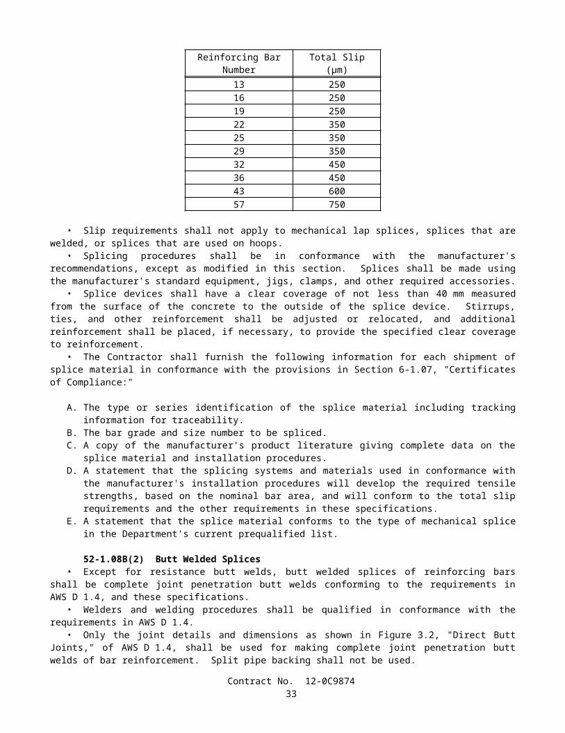
The eighth paragraph in Section 85-1.06, "Replacement," of the Standard Specifications is amended to read:
• Epoxy adhesive shall not be used to apply non-reflective plastic pavement markers.
SECTION 86: SIGNALS, LIGHTING AND ELECTRICAL SYSTEMS
Issue Date: June 19, 2003
The seventh paragraph of Section 86-2.03, "Foundations," of the Standard Specifications is amended to read:
• Forms shall be true to line and grade. Tops of foundations for posts and standards, except special foundations, shall be finished to curb or sidewalk grade or as directed by the Engineer. Forms shall be rigid and securely braced in place. Conduit ends and anchor bolts shall be placed in proper position and to proper height, and anchor bolts shall be held in place by means of rigid top and bottom templates. The bottom template shall be made of steel. The bottom template shall provide proper spacing and alignment of the anchor bolts near their bottom embedded end. The bottom template shall be installed before placing footing concrete. Anchor bolts shall not be installed more than 1:40 from vertical.
Section 86-2.03, "Foundations," of the Standard Specifications is amended by deleting the eighth paragraph.
The twelfth paragraph of Section 86-2.03, "Foundations," of the Standard Specifications is amended to read:
• Plumbing of the standards shall be accomplished by adjusting the leveling nuts before placing the mortar or before the foundation is finished to final grade. Shims, or other similar devices shall not be used for plumbing or raking of posts, standards or pedestals. After final adjustments of both top nuts and leveling nuts on anchorage assemblies have been made, firm contact shall exist between all bearing surfaces of the anchor bolt nuts, washers, and the base plate.
The first paragraph of Section 86-2.04, "Standards, Steel Pedestals and Posts," of the Standard Specifications is amended to read:
• Standards for traffic signals and lighting, and steel pedestals for cabinets and other similar equipment, shall be located as shown on the plans. Bolts, nuts and washers, and anchor bolts for use in signal and lighting support structures shall conform to the provisions in Section 55-2, "Materials." Except when bearing-type connections or slipbases are specified, high-strength bolted connections shall conform to the provisions in Section 55-3.14, "Bolted Connections." Welding, nondestructive testing (NDT) of welds, and acceptance and repair criteria for NDT of steel members shall conform to the requirements of AWS D1.1 and the contract special provisions.
The second paragraph of Section 86-2.04, "Standards, Steel Pedestals and Posts," of the Standard Specifications is amended to read:
• On each lighting standard except Type 1, one rectangular corrosion resistant metal identification tag shall be permanently attached above the hand hole, near the base of the standard, using stainless steel rivets. On each signal pole support, two corrosion resistant metal identification tags shall be attached, one above the hand hole near the base of the vertical standard and one on the underside of the signal mast arm near the arm plate. As a minimum, the information on each identification tag shall include the name of the manufacturer, the date of manufacture, the identification number as shown on the plans, the contract number, and a unique identification code assigned by the fabricator. This number shall be traceable to a particular contract and the welds on that component, and shall be readable after the support structure is coated and installed. The lettering shall be a minimum of 7 mm high. The information may be either depressed or raised, and shall be legible.
The fourth paragraph of Section 86-2.04, "Standards, Steel Pedestals and Posts" of the Standard Specifications is amended to read:
• Ferrous metal parts of standards, with shaft length of 4.6 m and longer, shall conform to the details shown on the plans, the provisions in Section 55, "Steel Structures," except as otherwise noted, and the following requirements:
Except as otherwise specified, standards shall be fabricated from sheet steel of weldable grade having a minimum yield strength, after fabrication, of 276 MPa.
Contract No. 12-0C987435
Certified test reports which verify conformance to the minimum yield strength requirements shall be submitted to the Engineer. The test reports may be the mill test reports for the as-received steel or, when the as-received steel has a lower yield strength than required, the Contractor shall provide supportive test data which provides assurance that the Contractor's method of cold forming will consistently increase the tensile properties of the steel to meet the specified minimum yield strength. The supportive test data shall include tensile properties of the steel after cold forming for specific heats and thicknesses.
When a single-ply 8-mm thick pole is specified, a 2-ply pole with equivalent section modulus may be substituted.Standards may be fabricated of full-length sheets or shorter sections. Each section shall be fabricated from not more
than 2 pieces of sheet steel. Where 2 pieces are used, the longitudinal welded seams shall be directly opposite one another. When the sections are butt-welded together, the longitudinal welded seams on adjacent sections shall be placed to form continuous straight seams from base to top of standard.
Butt-welded circumferential joints of tubular sections requiring CJP groove welds shall be made using a metal sleeve backing ring inside each joint. The sleeve shall be 3-mm nominal thickness, or thicker, and manufactured from steel having the same chemical composition as the steel in the tubular sections to be joined. When the sections to be joined have different specified minimum yield strengths, the steel in the sleeve shall have the same chemical composition as the tubular section having the higher minimum yield strength. The width of the metal sleeve shall be consistent with the type of NDT chosen and shall be a minimum width of 25 mm. The sleeve shall be centered at the joint and be in contact with the tubular section at the point of the weld at time of fit-up.
Welds shall be continuous.The weld metal at the transverse joint shall extend to the sleeve, making the sleeve an integral part of the joint.During fabrication, longitudinal seams on vertical tubular members of cantilevered support structures shall be
centered on and along the side of the pole that the pole plate is located. Longitudinal seams on horizontal tubular members, including signal and luminaire arms, shall be within +/-45 degrees of the bottom of the arm.
The longitudinal welds in steel tubular sections may be made by the electric resistance welding process.Longitudinal seam welds shall have 60 percent minimum penetration, except that within 150 mm of circumferential
welds, longitudinal seam welds shall be CJP groove welds. In addition, longitudinal seam welds on lighting support structures having telescopic pole segment splices shall be CJP groove welds on the female end for a length on each end equal to the designated slip fit splice length plus 150 mm.
Exposed circumferential welds, except fillet and fatigue-resistant welds, shall be ground flush (-0, +2mm) with the base metal prior to galvanizing or painting.
Circumferential welds and base plate-to-pole welds may be repaired only one time without written permission from the Engineer.
Exposed edges of the plates that make up the base assembly shall be finished smooth and exposed corners of the plates shall be broken unless otherwise shown on the plans. Shafts shall be provided with slip-fitter shaft caps.
Flatness of surfaces of 1) base plates that are to come in contact with concrete, grout, or washers and leveling nuts 2) plates in high-strength bolted connections, 3) plates in joints where cap screws are used to secure luminaire and signal arms, and 4) plates used for breakaway slip base assemblies shall conform to the requirements of ASTM A6.
Standards shall be straight, with a permissive variation not to exceed 25 mm measured at the midpoint of a 9-m or 11-m standard and not to exceed 20 mm measured at the midpoint of a 5-m through 6-m standard. Variation shall not exceed 25 mm at a point 4.5 m above the base plate for Type 35 and Type 36 standards.
Zinc-coated nuts used on fastener assemblies having a specified preload (obtained by specifying a prescribed tension, torque value, or degree of turn) shall be provided with a colored lubricant that is clean and dry to the touch. The color of the lubricant shall be in contrast to the zinc coating on the nut so that the presence of the lubricant is visually obvious. In addition, either the lubricant shall be insoluble in water, or fastener components shall be shipped to the job site in a sealed container.
No holes shall be made in structural members unless the holes are shown on the plans or are approved in writing by the Engineer.
Standards with an outside diameter of 300 mm or less shall be round. Standards with an outside diameter greater than 300 mm shall be round or multisided. Multisided standards shall have a minimum of 12 sides which shall be convex and shall have a minimum bend radius of 100 mm.
Mast arms for standards shall be fabricated from material as specified for standards, and shall conform to the dimensions shown on the plans.
The cast steel option for slip bases shall be fabricated from material conforming to the requirements in ASTM Designation: A 27/A 27M, Grade 70-40. Other comparable material may be used if written permission is given by the Engineer. The casting tolerances shall be in conformance with the Steel Founder's Society of America recommendations (green sand molding).
One casting from each lot of 50 castings or less shall be subject to radiographic inspection, in conformance with the requirements in ASTM Designation: E 94. The castings shall comply with the acceptance criteria severity level 3 or
Contract No. 12-0C987436
better for the types and categories of discontinuities in conformance with the requirements in ASTM Designations: E 186 and E 446. If the one casting fails to pass the inspection, 2 additional castings shall be radiographed. Both of these castings shall pass the inspection or the entire lot of 50 will be rejected.
Material certifications, consisting of physical and chemical properties, and radiographic films of the castings shall be filed at the manufacturer's office. These certifications and films shall be available for inspection upon request.
High-strength bolts, nuts and flat washers used to connect slip base plates shall conform to the requirements in ASTM Designation: A 325 or A 325M and shall be galvanized in conformance with the provisions in Section 75-1.05, "Galvanizing."
Plate washers shall be fabricated by saw cutting and drilling steel plate conforming to the requirements in AISI Designation: 1018, and be galvanized in conformance with the provisions in Section 75-1.05, "Galvanizing." Prior to galvanizing, burrs and sharp edges shall be removed and holes shall be chamfered sufficiently on each side to allow the bolt head to make full contact with the washer without tension on the bolt.
High-strength cap screws shown on the plans for attaching arms to standards shall conform to the requirements in ASTM Designation: A 325, A 325M or ASTM Designation: A 449, and shall comply with the mechanical requirements in ASTM Designation: A 325 or A 325M after galvanizing. The cap screws shall be galvanized in conformance with the provisions in Section 75-1.05, "Galvanizing." The threads of the cap screws shall be coated with a colored lubricant that is clean and dry to the touch. The color of the lubricant shall be in contrast to the color of the zinc coating on the cap screw so that presence of the lubricant is visually obvious. In addition, either the lubricant shall be insoluble in water, or fastener components shall be shipped to the job site in a sealed container.
Unless otherwise specified, bolted connections attaching signal or luminaire arms to poles shall be considered slip critical. Galvanized faying surfaces on plates on luminaire and signal arms and matching plate surfaces on poles shall be roughened by hand using a wire brush prior to assembly and shall conform to the requirements for Class C surface conditions for slip-critical connections in "Specification for Structural Joints Using ASTM A 325 or A 490 Bolts," a specification approved by the Research Council on Structural Connections (RCSC) of the Engineering Foundation. For faying surfaces required to be painted, the paint shall be an approved type, brand, and thickness that has been tested and approved according to the RCSC Specification as a Class B coating.
Samples of fastener components will be randomly taken from each production lot by the Engineer and submitted, along with test reports required by appropriate ASTM fastener specifications, for QA testing and evaluation. Sample sizes for each fastener component shall be as determined by the Engineer.
The seventh paragraph of 86-2.04, "Standards, Steel Pedestals and Posts" of the Standard Specifications is amended to read:
• To avoid interference of arm plate-to-tube welds with cap screw heads, and to ensure cap screw heads can be turned using conventional installation tools, fabricators shall make necessary adjustments to details prior to fabrication and properly locate the position of arm tubes on arm plates during fabrication.
Section 86-8.01, "Payment," of the Standard Specifications is amended by adding the following paragraph after the first paragraph:
• If a portion or all of the poles for signal, lighting and electrical systems pursuant to Standard Specification Section 86, "Signals, Lighting and Electrical Systems," is fabricated more than 480 air line kilometers from both Sacramento and Los Angeles, additional shop inspection expenses will be sustained by the State. Whereas it is and will be impracticable and extremely difficult to ascertain and determine the actual increase in such expenses, it is agreed that payment to the Contractor for furnishing such items from each fabrication site located more than 480 air line kilometers from both Sacramento and Los Angeles will be reduced $5000; in addition, in the case where a fabrication site is located more than 4800 air line kilometers from both Sacramento and Los Angeles, payment will be reduced an additional $3000 per each fabrication site ($8000 total per site).
SECTION 88: ENGINEERING FABRIC
Issue Date: January 15, 2002
Section 88-1.02, "Pavement Reinforcing Fabric," of the Standard Specifications is amended to read:
• Pavement reinforcing fabric shall be 100 percent polypropylene staple fiber fabric material, needle-punched, thermally bonded on one side, and conform to the following:
Contract No. 12-0C987437
Specification RequirementWeight, grams per square meterASTM Designation: D 5261 140Grab tensile strength(25-mm grip), kilonewtons, min. in each directionASTM Designation: D 4632 0.45Elongation at break, percent min.ASTM Designation: D 4632 50Asphalt retention by fabric, grams per square meter. (Residual Minimum)ASTM Designation: D 6140 900Note: Weight, grab, elongation and asphalt retention are based on Minimum Average Roll Value (MARV)
SECTION 90: PORTLAND CEMENT CONCRETE
Issue Date: June 19, 2003
Section 90, "Portland Cement Concrete," of the Standard Specifications is amended to read:
SECTION 90: PORTLAND CEMENT CONCRETE90-1 GENERAL
90-1.01 DESCRIPTION• Portland cement concrete shall be composed of cementitious material, fine aggregate, coarse aggregate, admixtures
if used, and water, proportioned and mixed as specified in these specifications.• The Contractor shall determine the mix proportions for concrete in conformance with these specifications. Unless
otherwise specified, cementitious material shall be a combination of cement and mineral admixture. Cementitious material shall be either:
1. "Type IP (MS) Modified" cement; or 2. A combination of "Type II Modified" portland cement and mineral admixture; or3. A combination of Type V portland cement and mineral admixture.
• Type III portland cement shall be used only as allowed in the special provisions or with the approval of the Engineer.
• Class 1 concrete shall contain not less than 400 kg of cementitious material per cubic meter.• Class 2 concrete shall contain not less than 350 kg of cementitious material per cubic meter.• Class 3 concrete shall contain not less than 300 kg of cementitious material per cubic meter.• Class 4 concrete shall contain not less than 250 kg of cementitious material per cubic meter.• Minor concrete shall contain not less than 325 kg of cementitious material per cubic meter unless otherwise
specified in these specifications or the special provisions.• Unless otherwise designated on the plans or specified in these specifications or the special provisions, the amount of
cementitious material used per cubic meter of concrete in structures or portions of structures shall conform to the following:
Use Cementitious Material Content(kg/m3)
Concrete designated by compressive strength:Deck slabs and slab spans of bridgesRoof sections of exposed top box culvertsOther portions of structures
400 min., 475 max.400 min., 475 max.350 min., 475 max.
Concrete not designated by compressive strength:Deck slabs and slab spans of bridgesRoof sections of exposed top box culvertsPrestressed membersSeal coursesOther portions of structures
400 min.400 min.400 min.400 min.350 min.
Concrete for precast members 350 min., 550 max.Contract No. 12-0C9874
38

• Whenever the 28-day compressive strength shown on the plans is greater than 25 MPa, the concrete shall be designated by compressive strength. If the plans show a 28-day compressive strength that is 28 MPa or greater, an additional 14 days will be allowed to obtain the specified strength. The 28-day compressive strengths shown on the plans that are 25 MPa or less are shown for design information only and are not a requirement for acceptance of the concrete.
• Concrete designated by compressive strength shall be proportioned such that the concrete will attain the strength shown on the plans or specified in the special provisions.
• Before using concrete for which the mix proportions have been determined by the Contractor, or in advance of revising those mix proportions, the Contractor shall submit in writing to the Engineer a copy of the mix design.
• Compliance with cementitious material content requirements will be verified in conformance with procedures described in California Test 518 for cement content. For testing purposes, mineral admixture shall be considered to be cement. Batch proportions shall be adjusted as necessary to produce concrete having the specified cementitious material content.
• If any concrete has a cementitious material, portland cement, or mineral admixture content that is less than the minimum required, the concrete shall be removed. However, if the Engineer determines that the concrete is structurally adequate, the concrete may remain in place and the Contractor shall pay to the State $0.55 for each kilogram of cementitious material, portland cement, or mineral admixture that is less than the minimum required. The Department may deduct the amount from any moneys due, or that may become due, the Contractor under the contract. The deductions will not be made unless the difference between the contents required and those actually provided exceeds the batching tolerances permitted by Section 90-5, "Proportioning." No deductions will be made based on the results of California Test 518.
• The requirements of the preceding paragraph shall not apply to minor concrete or commercial quality concrete.
90-2 MATERIALS
90-2.01 CEMENT• Unless otherwise specified, cement shall be either "Type IP (MS) Modified" cement, "Type II Modified" portland
cement or Type V portland cement.• "Type IP (MS) Modified" cement shall conform to the requirements for Type IP (MS) cement in ASTM
Designation: C 595, and shall be comprised of an intimate and uniform blend of Type II cement and not more than 35 percent by mass of mineral admixture. The type and minimum amount of mineral admixture used in the manufacture of "Type IP (MS) Modified" cement shall be in conformance with the provisions in Section 90-4.08, "Required Use of Mineral Admixtures."
• "Type II Modified" portland cement shall conform to the requirements for Type II portland cement in ASTM Designation: C 150.
• In addition, "Type IP (MS) Modified" cement and "Type II Modified" portland cement shall conform to the following requirements:
A. The cement shall not contain more than 0.60-percent by mass of alkalies, calculated as the percentage of Na2O plus 0.658 times the percentage of K2O, when determined by either direct intensity flame photometry or by the atomic absorption method. The instrument and procedure used shall be qualified as to precision and accuracy in conformance with the requirements in ASTM Designation: C 114;
B. The autoclave expansion shall not exceed 0.50-percent; andC. Mortar, containing the cement to be used and Ottawa sand, when tested in conformance with California Test 527,
shall not expand in water more than 0.010 percent and shall not contract in air more than 0.048 percent, except that when cement is to be used for precast prestressed concrete piling, precast prestressed concrete members, or steam cured concrete products, the mortar shall not contract in air more than 0.053 percent.
• Type III and Type V portland cements shall conform to the requirements in ASTM Designation: C 150 and the additional requirements listed above for "Type II Modified" portland cement, except that when tested in conformance with California Test 527, mortar containing Type III portland cement shall not contract in air more than 0.075 percent.
• Cement used in the manufacture of cast-in-place concrete for exposed surfaces of like elements of a structure shall be from the same cement mill.
• Cement shall be protected from exposure to moisture until used. Sacked cement shall be piled to permit access for tally, inspection, and identification of each shipment.
• Adequate facilities shall be provided to assure that cement meeting the provisions specified in this Section 90 -2.01 shall be kept separate from other cement in order to prevent any but the specified cement from entering the work. Safe and suitable facilities for sampling cement shall be provided at the weigh hopper or in the feed line immediately in advance of the hopper, in conformance with California Test 125.
Contract No. 12-0C987439
• If cement is used prior to sampling and testing as provided in Section 6-1.07, "Certificates of Compliance," and the cement is delivered directly to the site of the work, the Certificate of Compliance shall be signed by the cement manufacturer or supplier of the cement. If the cement is used in ready-mixed concrete or in precast concrete products purchased as such by the Contractor, the Certificate of Compliance shall be signed by the manufacturer of the concrete or product.
• Cement furnished without a Certificate of Compliance shall not be used in the work until the Engineer has had sufficient time to make appropriate tests and has approved the cement for use.
90-2.02 AGGREGATES• Aggregates shall be free from deleterious coatings, clay balls, roots, bark, sticks, rags, and other extraneous material.• Natural aggregates shall be thoroughly and uniformly washed before use.• The Contractor, at the Contractor's expense, shall provide safe and suitable facilities, including necessary splitting
devices for obtaining samples of aggregates, in conformance with California Test 125.• Aggregates shall be of such character that it will be possible to produce workable concrete within the limits of water
content provided in Section 90-6.06, "Amount of Water and Penetration."• Aggregates shall have not more than 10 percent loss when tested for soundness in conformance with the
requirements in California Test 214. The soundness requirement for fine aggregate will be waived, provided that the durability index, Df, of the fine aggregate is 60, or greater, when tested for durability in conformance with California Test 229.
• If the results of any one or more of the Cleanness Value, Sand Equivalent, or aggregate grading tests do not meet the requirements specified for "Operating Range" but all meet the "Contract Compliance" requirements, the placement of concrete shall be suspended at the completion of the current pour until tests or other information indicate that the next material to be used in the work will comply with the requirements specified for "Operating Range."
• If the results of either or both the Cleanness Value and coarse aggregate grading tests do not meet the requirements specified for "Contract Compliance," the concrete that is represented by the tests shall be removed. However, if the Engineer determines that the concrete is structurally adequate, the concrete may remain in place, and the Contractor shall pay to the State $4.60 per cubic meter for paving concrete and $7.20 per cubic meter for all other concrete for the concrete represented by these tests and left in place. The Department may deduct the amount from any moneys due, or that may become due, the Contractor under the contract.
• If the results of either or both the Sand Equivalent and fine aggregate grading tests do not meet the requirements specified for "Contract Compliance," the concrete which is represented by the tests shall be removed. However, if the Engineer determines that the concrete is structurally adequate, the concrete may remain in place, and the Contractor shall pay to the State $4.60 per cubic meter for paving concrete and $7.20 per cubic meter for all other concrete for the concrete represented by these tests and left in place. The Department may deduct the amount from any moneys due, or that may become due, the Contractor under the contract.
• The 2 preceding paragraphs apply individually to the "Contract Compliance" requirements for coarse aggregate and fine aggregate. When both coarse aggregate and fine aggregate do not conform to the "Contract Compliance" requirements, both paragraphs shall apply. The payments specified in those paragraphs shall be in addition to any payments made in conformance with the provisions in Section 90-1.01, "Description."
• No single Cleanness Value, Sand Equivalent or aggregate grading test shall represent more than 250 m3 of concrete or one day's pour, whichever is smaller.
• When the source of an aggregate is changed, the Contractor shall adjust the mix proportions and submit in writing to the Engineer a copy of the mix design before using the aggregates.
90-2.02A Coarse Aggregate• Coarse aggregate shall consist of gravel, crushed gravel, crushed rock, crushed air-cooled iron blast furnace slag or
combinations thereof. Crushed air-cooled blast furnace slag shall not be used in reinforced or prestressed concrete.• Coarse aggregate shall conform to the following quality requirements:
TestsCalifornia
Test RequirementsLoss in Los Angeles Rattler (after 500 revolutions)
211 45% max.
Cleanness ValueOperating Range 227 75 min.Contract Compliance 227 71 min.
• In lieu of the above Cleanness Value requirements, a Cleanness Value "Operating Range" limit of 71, minimum, and a Cleanness Value "Contract Compliance" limit of 68, minimum, will be used to determine the acceptability of the coarse
Contract No. 12-0C987440
aggregate if the Contractor furnishes a Certificate of Compliance, as provided in Section 6-1.07, "Certificates of Compliance," certifying that:
1. coarse aggregate sampled at the completion of processing at the aggregate production plant had a Cleanness Value of not less than 82 when tested by California Test 227; and
2. prequalification tests performed in conformance with the requirements in California Test 549 indicated that the aggregate would develop a relative strength of not less than 95 percent and would have a relative shrinkage not greater than 105 percent, based on concrete.
90-2.02B Fine Aggregate• Fine aggregate shall consist of natural sand, manufactured sand produced from larger aggregate or a combination
thereof. Manufactured sand shall be well graded.
• Fine aggregate shall conform to the following quality requirements:
TestCalifornia
Test RequirementsOrganic Impurities 213 Satisfactorya
Mortar Strengths Relative to Ottawa Sand 515 95%, min.Sand Equivalent:
Operating Range 217 75, min.Contract Compliance 217 71, min.
a Fine aggregate developing a color darker than the reference standard color solution may be accepted if it is determined by the Engineer, from mortar strength tests, that a darker color is acceptable.
• In lieu of the above Sand Equivalent requirements, a Sand Equivalent "Operating Range" limit of 71 minimum and a Sand Equivalent "Contract Compliance" limit of 68 minimum will be used to determine the acceptability of the fine aggregate if the Contractor furnishes a Certificate of Compliance, as provided in Section 6-1.07, "Certificates of Compliance," certifying that:
1. fine aggregate sampled at the completion of processing at the aggregate production plant had a Sand Equivalent value of not less than 82 when tested by California Test 217; and
2. prequalification tests performed in conformance with California Test 549 indicated that the aggregate would develop a relative strength of not less than 95 percent and would have a relative shrinkage not greater than 105 percent, based on concrete.
90-2.03 WATER• In conventionally reinforced concrete work, the water for curing, for washing aggregates, and for mixing shall be
free from oil and shall not contain more than 1000 parts per million of chlorides as Cl, when tested in conformance with California Test 422, nor more than 1300 parts per million of sulfates as SO4, when tested in conformance with California Test 417. In prestressed concrete work, the water for curing, for washing aggregates, and for mixing shall be free from oil and shall not contain more than 650 parts per million of chlorides as Cl, when tested in conformance with California Test 422, nor more than 1300 parts per million of sulfates as SO4, when tested in conformance with California Test 417. In no case shall the water contain an amount of impurities that will cause either: 1) a change in the setting time of cement of more than 25 percent when tested in conformance with the requirements in ASTM Designation: C 191 or ASTM Designation: C 266 or 2) a reduction in the compressive strength of mortar at 14 days of more than 5 percent, when tested in conformance with the requirements in ASTM Designation: C 109, when compared to the results obtained with distilled water or deionized water, tested in conformance with the requirements in ASTM Designation: C 109.
• In non-reinforced concrete work, the water for curing, for washing aggregates and for mixing shall be free from oil and shall not contain more than 2000 parts per million of chlorides as Cl, when tested in conformance with California Test 422, or more than 1500 parts per million of sulfates as SO4, when tested in conformance with California Test 417.
• In addition to the above provisions, water for curing concrete shall not contain impurities in a sufficient amount to cause discoloration of the concrete or produce etching of the surface.
• Water reclaimed from mixer wash-out operations may be used in mixing concrete. The water shall not contain coloring agents or more than 300 parts per million of alkalis (Na2O + 0.658 K2O) as determined on the filtrate. The specific gravity of the water shall not exceed 1.03 and shall not vary more than ±0.010 during a day's operations.
Contract No. 12-0C987441
90-2.04 ADMIXTURE MATERIALS• Admixture materials shall conform to the requirements in the following ASTM Designations:
A. Chemical Admixtures—ASTM Designation: C 494.B. Air-entraining Admixtures—ASTM Designation: C 260.C. Calcium Chloride—ASTM Designation: D 98.D. Mineral Admixtures—Coal fly ash; raw or calcined natural pozzolan as specified in ASTM Designation: C 618;
silica fume conforming to the requirements in ASTM Designation: C 1240, with reduction of mortar expansion of 80 percent, minimum, using the cement from the proposed mix design.
• Unless otherwise specified in the special provisions, mineral admixtures shall be used in conformance with the provisions in Section 90-4.08, "Required Use of Mineral Admixtures."
90-3 AGGREGATE GRADINGS
90-3.01 GENERAL• Before beginning concrete work, the Contractor shall submit in writing to the Engineer the gradation of the primary
aggregate nominal sizes that the Contractor proposes to furnish. If a primary coarse aggregate or the fine aggregate is separated into 2 or more sizes, the proposed gradation shall consist of the gradation for each individual size, and the proposed proportions of each individual size, combined mathematically to indicate one proposed gradation. The proposed gradation shall meet the grading requirements shown in the table in this section, and shall show the percentage passing each of the sieve sizes used in determining the end result.
• The Engineer may waive, in writing, the gradation requirements in this Section 90-3.01 and in Sections 90-3.02, "Coarse Aggregate Grading," 90-3.03, "Fine Aggregate Grading," and 90-3.04, "Combined Aggregate Gradings," if, in the Engineer's opinion, furnishing the gradation is not necessary for the type or amount of concrete work to be constructed.
• Gradations proposed by the Contractor shall be within the following percentage passing limits:
Primary Aggregate Nominal Size Sieve Size Limits of Proposed Gradation37.5-mm x 19-mm 25-mm 19 - 4125-mm x 4.75-mm 19-mm 52 - 8525-mm x 4.75-mm 9.5-mm 15 - 3812.5-mm x 4.75-mm 9.5-mm 40 - 78 9.5-mm x 2.36-mm 9.5-mm 50 - 85 Fine Aggregate 1.18-mm 55 - 75Fine Aggregate 600-µm 34 - 46Fine Aggregate 300-µm 16 - 29
• Should the Contractor change the source of supply, the Contractor shall submit in writing to the Engineer the new gradations before their intended use.
90-3.02 COARSE AGGREGATE GRADING• The grading requirements for coarse aggregates are shown in the following table for each size of coarse aggregate:
Contract No. 12-0C987442
Percentage Passing Primary Aggregate Nominal Sizes37.5-mm x 19-mm 25-mm x 4.75-mm 12.5-mm x 4.75-mm 9.5-mm x 2.36-mm
Operating Contract Operating Contract Operating Contract Operating ContractSieve Sizes Range Compliance Range Compliance Range Compliance Range Compliance50-mm 100 100 — — — — — —37.5-mm 88-100 85-100 100 100 — — — —25-mm x ± 18 X ± 25 88-100 86-100 — — — —19-mm 0-17 0-20 X ± 15 X ± 22 100 100 — —12.5-mm — — — — 82-100 80-100 100 1009.5-mm 0-7 0-9 X ± 15 X ± 22 X ± 15 X ± 22 X ± 15 X ± 204.75-mm — — 0-16 0-18 0-15 0-18 0-25 0-282.36-mm — — 0-6 0-7 0-6 0-7 0-6 0-7
• In the above table, the symbol X is the gradation that the Contractor proposes to furnish for the specific sieve size as provided in Section 90-3.01, "General."
• Coarse aggregate for the 37.5-mm, maximum, combined aggregate grading as provided in Section 90-3.04, "Combined Aggregate Gradings," shall be furnished in 2 or more primary aggregate nominal sizes. Each primary aggregate nominal size may be separated into 2 sizes and stored separately, provided that the combined material conforms to the grading requirements for that particular primary aggregate nominal size.
• When the 25-mm, maximum, combined aggregate grading as provided in Section 90-3.04, "Combined Aggregate Gradings," is to be used, the coarse aggregate may be separated into 2 sizes and stored separately, provided that the combined material shall conform to the grading requirements for the 25-mm x 4.75-mm primary aggregate nominal size.
90-3.03 FINE AGGREGATE GRADING• Fine aggregate shall be graded within the following limits:
Percentage PassingSieve Sizes Operating Range Contract Compliance
9.5-mm 100 1004.75-mm 95-100 93-1002.36-mm 65-95 61-991.18-mm X ± 10 X ± 13600-µm X ± 9 X ± 12300-µm X ± 6 X ± 9150-µm 2-12 1-1575-µm 0-8 0-10
• In the above table, the symbol X is the gradation that the Contractor proposes to furnish for the specific sieve size as provided in Section 90-3.01, "General."
• In addition to the above required grading analysis, the distribution of the fine aggregate sizes shall be such that the difference between the total percentage passing the 1.18-mm sieve and the total percentage passing the 600-µm sieve shall be between 10 and 40, and the difference between the percentage passing the 600-µm and 300-µm sieves shall be between 10 and 40.
• Fine aggregate may be separated into 2 or more sizes and stored separately, provided that the combined material conforms to the grading requirements specified in this Section 90-3.03.
90-3.04 COMBINED AGGREGATE GRADINGS• Combined aggregate grading limits shall be used only for the design of concrete mixes. Concrete mixes shall be
designed so that aggregates are combined in proportions that shall produce a mixture within the grading limits for combined aggregates as specified herein. Within these limitations, the relative proportions shall be as ordered by the Engineer, except as otherwise provided in Section 90-1.01, "Description."
• The combined aggregate grading, except when otherwise specified in these specifications or the special provisions, shall be either the 37.5-mm, maximum grading, or the 25-mm, maximum grading, at the option of the Contractor.
Contract No. 12-0C987443
Grading Limits of Combined AggregatesPercentage Passing
Sieve Sizes 37.5-mm Max. 25-mm Max. 12.5-mm Max. 9.5-mm Max.50-mm 100 — — —37.5-mm 90-100 100 — —25-mm 50-86 90-100 — —19-mm 45-75 55-100 100 —12.5-mm — — 90-100 1009.5-mm 38-55 45-75 55-86 50 - 1004.75-mm 30-45 35-60 45-63 45 - 632.36-mm 23-38 27-45 35-49 35 - 491.18-mm 17-33 20-35 25-37 25 - 37600-µm 10-22 12-25 15-25 15 - 25300-µm 4-10 5-15 5-15 5 - 15150-µm 1-6 1-8 1-8 1 - 875-µm 0-3 0-4 0-4 0 - 4
• Changes from one grading to another shall not be made during the progress of the work unless permitted by the Engineer.
90-4 ADMIXTURES90-4.01 GENERAL
• Admixtures used in portland cement concrete shall conform to and be used in conformance with the provisions in this Section 90-4 and the special provisions. Admixtures shall be used when specified or ordered by the Engineer and may be used at the Contractor's option as provided herein.
• Chemical admixtures and air-entraining admixtures containing chlorides as Cl in excess of one percent by mass of admixture, as determined by California Test 415, shall not be used in prestressed or reinforced concrete.
• Calcium chloride shall not be used in concrete except when otherwise specified.• Mineral admixture used in concrete for exposed surfaces of like elements of a structure shall be from the same
source and of the same percentage.• Admixtures shall be uniform in properties throughout their use in the work. Should it be found that an admixture as
furnished is not uniform in properties, its use shall be discontinued.• If more than one admixture is used, the admixtures shall be compatible with each other so that the desirable effects
of all admixtures used will be realized.
90-4.02 MATERIALS• Admixture materials shall conform to the provisions in Section 90–2.04, "Admixture Materials."
90-4.03 ADMIXTURE APPROVAL• No admixture brand shall be used in the work unless it is on the Department's current list of approved brands for the
type of admixture involved.• Admixture brands will be considered for addition to the approved list if the manufacturer of the admixture submits
to the Transportation Laboratory a sample of the admixture accompanied by certified test results demonstrating that the admixture complies with the requirements in the appropriate ASTM Designation and these specifications. The sample shall be sufficient to permit performance of all required tests. Approval of admixture brands will be dependent upon a determination as to compliance with the requirements, based on the certified test results submitted, together with tests the Department may elect to perform.
• When the Contractor proposes to use an admixture of a brand and type on the current list of approved admixture brands, the Contractor shall furnish a Certificate of Compliance from the manufacturer, as provided in Section 6 -1.07, "Certificates of Compliance," certifying that the admixture furnished is the same as that previously approved. If a previously approved admixture is not accompanied by a Certificate of Compliance, the admixture shall not be used in the work until the Engineer has had sufficient time to make the appropriate tests and has approved the admixture for use. The Engineer may take samples for testing at any time, whether or not the admixture has been accompanied by a Certificate of Compliance.
• If a mineral admixture is delivered directly to the site of the work, the Certificate of Compliance shall be signed by the manufacturer or supplier of the mineral admixture. If the mineral admixture is used in ready-mix concrete or in precast
Contract No. 12-0C987444
concrete products purchased as such by the Contractor, the Certificate of Compliance shall be signed by the manufacturer of the concrete or product.
90-4.04 REQUIRED USE OF CHEMICAL ADMIXTURES AND CALCIUM CHLORIDE• When the use of a chemical admixture or calcium chloride is specified, the admixture shall be used at the dosage
specified, except that if no dosage is specified, the admixture shall be used at the dosage normally recommended by the manufacturer of the admixture.
• Calcium chloride shall be dispensed in liquid, flake, or pellet form. Calcium chloride dispensed in liquid form shall conform to the provisions for dispensing liquid admixtures in Section 90-4.10, "Proportioning and Dispensing Liquid Admixtures."
90-4.05 OPTIONAL USE OF CHEMICAL ADMIXTURES• The Contractor will be permitted to use Type A or F, water-reducing; Type B, retarding; or Type D or G,
water-reducing and retarding admixtures as described in ASTM Designation: C 494 to conserve cementitious material or to facilitate any concrete construction application subject to the following conditions:
A. When a water-reducing admixture or a water-reducing and retarding admixture is used, the cementitious material content specified or ordered may be reduced by a maximum of 5 percent by mass, except that the resultant cementitious material content shall be not less than 300 kilograms per cubic meter; and
B. When a reduction in cementitious material content is made, the dosage of admixture used shall be the dosage used in determining approval of the admixture.
• Unless otherwise specified, a Type C accelerating chemical admixture conforming to the requirements in ASTM Designation: C 494, may be used in portland cement concrete. Inclusion in the mix design submitted for approval will not be required provided that the admixture is added to counteract changing conditions that contribute to delayed setting of the portland cement concrete, and the use or change in dosage of the admixture is approved in writing by the Engineer.
90-4.06 REQUIRED USE OF AIR-ENTRAINING ADMIXTURES• When air-entrainment is specified or ordered by the Engineer, the air-entraining admixture shall be used in amounts
to produce a concrete having the specified air content as determined by California Test 504.
90-4.07 OPTIONAL USE OF AIR-ENTRAINING ADMIXTURES• When air-entrainment has not been specified or ordered by the Engineer, the Contractor will be permitted to use an
air-entraining admixture to facilitate the use of any construction procedure or equipment provided that the average air content, as determined by California Test 504, of 3 successive tests does not exceed 4 percent, and no single test value exceeds 5.5 percent. If the Contractor elects to use an air-entraining admixture in concrete for pavement, the Contractor shall so indicate at the time the Contractor designates the source of aggregate as provided in Section 40-1.015, "Cement Content."
90-4.08 REQUIRED USE OF MINERAL ADMIXTURES• Unless otherwise specified, mineral admixture shall be combined with cement to make cementitious material.• The calcium oxide content of mineral admixtures shall not exceed 10 percent and the available alkali, as sodium
oxide equivalent, shall not exceed 1.5 percent when determined in conformance with the requirements in ASTM Designation: C 618.
• The amounts of cement and mineral admixture used in cementitious material shall be sufficient to satisfy the minimum cementitious material content requirements specified in Section 90-1.01, "Description," or Section 90-4.05, "Optional Use of Chemical Admixtures," and shall conform to the following:
A. The minimum amount of cement shall not be less than 75 percent by mass of the specified minimum cementitious material content;
B. The minimum amount of mineral admixture to be combined with cement shall be determined using one of the following criteria:
1. When the calcium oxide content of a mineral admixture is equal to or less than 2 percent by mass, the amount of mineral admixture shall not be less than 15 percent by mass of the total amount of cementitious material to be used in the mix;
Contract No. 12-0C987445
2. When the calcium oxide content of a mineral admixture is greater than 2 percent, the amount of mineral admixture shall not be less than 25 percent by mass of the total amount of cementitious material to be used in the mix;
3. When a mineral admixture that conforms to the provisions for silica fume in Section 90-2.04, "Admixture Materials," is used, the amount of mineral admixture shall not be less than 10 percent by mass of the total amount of cementitious material to be used in the mix
C. The total amount of mineral admixture shall not exceed 35 percent by mass of the total amount of cementitious material to be used in the mix. Where Section 90-1.01, "Description," specifies a maximum cementitious content in kilograms per cubic meter, the total mass of cement and mineral admixture per cubic meter shall not exceed the specified maximum cementitious material content.
90-4.09 BLANK
90-4.10 PROPORTIONING AND DISPENSING LIQUID ADMIXTURES• Chemical admixtures and air-entraining admixtures shall be dispensed in liquid form. Dispensers for liquid
admixtures shall have sufficient capacity to measure at one time the prescribed quantity required for each batch of concrete. Each dispenser shall include a graduated measuring unit into which liquid admixtures are measured to within ±5 percent of the prescribed quantity for each batch. Dispensers shall be located and maintained so that the graduations can be accurately read from the point at which proportioning operations are controlled to permit a visual check of batching accuracy prior to discharge. Each measuring unit shall be clearly marked for the type and quantity of admixture.
• Each liquid admixture dispensing system shall be equipped with a sampling device consisting of a valve located in a safe and readily accessible position such that a sample of the admixture may be withdrawn slowly by the Engineer.
• If more than one liquid admixture is used in the concrete mix, each liquid admixture shall have a separate measuring unit and shall be dispensed by injecting equipment located in such a manner that the admixtures are not mixed at high concentrations and do not interfere with the effectiveness of each other. When air -entraining admixtures are used in conjunction with other liquid admixtures, the air-entraining admixture shall be the first to be incorporated into the mix.
• When automatic proportioning devices are required for concrete pavement, dispensers for liquid admixtures shall operate automatically with the batching control equipment. The dispensers shall be equipped with an automatic warning system in good operating condition that will provide a visible or audible signal at the point at which proportioning operations are controlled when the quantity of admixture measured for each batch of concrete varies from the preselected dosage by more than 5 percent, or when the entire contents of the measuring unit are not emptied from the dispenser into each batch of concrete.
• Unless liquid admixtures are added to premeasured water for the batch, their discharge into the batch shall be arranged to flow into the stream of water so that the admixtures are well dispersed throughout the batch, except that air-entraining admixtures may be dispensed directly into moist sand in the batching bins provided that adequate control of the air content of the concrete can be maintained.
• Liquid admixtures requiring dosages greater than 2.5 L/m3 shall be considered to be water when determining the total amount of free water as specified in Section 90-6.06, "Amount of Water and Penetration."
• Special admixtures, such as "high range" water reducers that may contribute to a high rate of slump loss, shall be measured and dispensed as recommended by the admixture manufacturer and as approved by the Engineer.
90-4.11 STORAGE, PROPORTIONING, AND DISPENSING OF MINERAL ADMIXTURES• Mineral admixtures shall be protected from exposure to moisture until used. Sacked material shall be piled to permit
access for tally, inspection and identification for each shipment.• Adequate facilities shall be provided to assure that mineral admixtures meeting the specified requirements are kept
separate from other mineral admixtures in order to prevent any but the specified mineral admixtures from entering the work. Safe and suitable facilities for sampling mineral admixtures shall be provided at the weigh hopper or in the feed line immediately in advance of the hopper.
• Mineral admixtures shall be incorporated into concrete using equipment conforming to the requirements for cement weigh hoppers, and charging and discharging mechanisms in ASTM Designation: C 94, in Section 90-5.03, "Proportioning," and in this Section 90-4.11.
• When concrete is completely mixed in stationary paving mixers, the mineral admixture shall be weighed in a separate weigh hopper conforming to the provisions for cement weigh hoppers and charging and discharging mechanisms in Section 90-5.03A, "Proportioning for Pavement," and the mineral admixture and cement shall be introduced simultaneously into the mixer proportionately with the aggregate. If the mineral admixture is not weighed in a separate weigh hopper, the Contractor shall provide certification that the stationary mixer is capable of mixing the cement, admixture, aggregates and water uniformly prior to discharge. Certification shall contain the following:
Contract No. 12-0C987446
A. Test results for 2 compressive strength test cylinders of concrete taken within the first one-third and 2 compressive strength test cylinders of concrete taken within the last one-third of the concrete discharged from a single batch from the stationary paving mixer. Strength tests and cylinder preparation will be in conformance with the provisions of Section 90-9, "Compressive Strength;"
B. Calculations demonstrating that the difference in the averages of 2 compressive strengths taken in the first one-third is no greater than 7.5 percent different than the averages of 2 compressive strengths taken in the last one-third of the concrete discharged from a single batch from the stationary paving mixer. Strength tests and cylinder preparation will be in conformance with the provisions of Section 90-9, "Compressive Strength;" and
C. The mixer rotation speed and time of mixing prior to discharge that are required to produce a mix that meets the requirements above.
90-5 PROPORTIONING
90-5.01 STORAGE OF AGGREGATES• Aggregates shall be stored or stockpiled in such a manner that separation of coarse and fine particles of each size
shall be avoided and also that the various sizes shall not become intermixed before proportioning.• Aggregates shall be stored or stockpiled and handled in a manner that shall prevent contamination by foreign
materials. In addition, storage of aggregates at batching or mixing facilities that are erected subsequent to the award of the contract and that furnish concrete to the project shall conform to the following:
A. Intermingling of the different sizes of aggregates shall be positively prevented. The Contractor shall take the necessary measures to prevent intermingling. The preventive measures may include, but are not necessarily limited to, physical separation of stockpiles or construction of bulkheads of adequate length and height; and
B. Contamination of aggregates by contact with the ground shall be positively prevented. The Contractor shall take the necessary measures to prevent contamination. The preventive measures shall include, but are not necessarily limited to, placing aggregates on wooden platforms or on hardened surfaces consisting of portland cement concrete, asphalt concrete, or cement treated material.
• In placing aggregates in storage or in moving the aggregates from storage to the weigh hopper of the batching plant, any method that may cause segregation, degradation, or the combining of materials of different gradings that will result in any size of aggregate at the weigh hopper failing to meet the grading requirements, shall be discontinued. Any method of handling aggregates that results in excessive breakage of particles shall be discontinued. The use of suitable devices to reduce impact of falling aggregates may be required by the Engineer.
90-5.02 PROPORTIONING DEVICES• Weighing, measuring, or metering devices used for proportioning materials shall conform to the requirements in
Section 9-1.01, "Measurement of Quantities," and this Section 90-5.02. In addition, automatic weighing systems shall comply with the requirements for automatic proportioning devices in Section 90-5.03A, "Proportioning for Pavement." Automatic devices shall be automatic to the extent that the only manual operation required for proportioning the aggregates, cement, and mineral admixture for one batch of concrete is a single operation of a switch or starter.
• Proportioning devices shall be tested at the expense of the Contractor as frequently as the Engineer may deem necessary to ensure their accuracy.
• Weighing equipment shall be insulated against vibration or movement of other operating equipment in the plant. When the plant is in operation, the mass of each batch of material shall not vary from the mass designated by the Engineer by more than the tolerances specified herein.
• Equipment for cumulative weighing of aggregate shall have a zero tolerance of ±0.5 percent of the designated total batch mass of the aggregate. For systems with individual weigh hoppers for the various sizes of aggregate, the zero tolerance shall be ±0.5 percent of the individual batch mass designated for each size of aggregate. Equipment for cumulative weighing of cement and mineral admixtures shall have a zero tolerance of ±0.5 percent of the designated total batch mass of the cement and mineral admixture. Equipment for weighing cement or mineral admixture separately shall have a zero tolerance of ±0.5 percent of their designated individual batch masses. Equipment for measuring water shall have a zero tolerance of ±0.5 percent of its designated mass or volume.
• The mass indicated for any batch of material shall not vary from the preselected scale setting by more than the following:
A. Aggregate weighed cumulatively shall be within 1.0 percent of the designated total batch mass of the aggregate. Aggregates weighed individually shall be within 1.5 percent of their respective designated batch masses; and
Contract No. 12-0C987447

B. Cement shall be within 1.0 percent of its designated batch mass. When weighed individually, mineral admixture shall be within 1.0 percent of its designated batch mass. When mineral admixture and cement are permitted to be weighed cumulatively, cement shall be weighed first to within 1.0 percent of its designated batch mass, and the total for cement and mineral admixture shall be within 1.0 percent of the sum of their designated batch masses; and
C. Water shall be within 1.5 percent of its designated mass or volume.
• Each scale graduation shall be approximately 0.001 of the total capacity of the scale. The capacity of scales for weighing cement, mineral admixture, or cement plus mineral admixture and aggregates shall not exceed that of commercially available scales having single graduations indicating a mass not exceeding the maximum permissible mass variation above, except that no scale shall be required having a capacity of less than 500 kg, with 0.5-kg graduations.
90-5.03 PROPORTIONING• Proportioning shall consist of dividing the aggregates into the specified sizes, each stored in a separate bin, and
combining them with cement, mineral admixture, and water as provided in these specifications. Aggregates shall be proportioned by mass.
• At the time of batching, aggregates shall have been dried or drained sufficiently to result in a stable moisture content such that no visible separation of water from aggregate will take place during transportation from the proportioning plant to the point of mixing. In no event shall the free moisture content of the fine aggregate at the time of batching exceed 8 percent of its saturated, surface-dry mass.
• Should separate supplies of aggregate material of the same size group, but of different moisture content or specific gravity or surface characteristics affecting workability, be available at the proportioning plant, withdrawals shall be made from one supply exclusively and the materials therein completely exhausted before starting upon another.
• Bulk "Type IP (MS) Modified" cement shall be weighed in an individual hopper and shall be kept separate from the aggregates until the ingredients are released for discharge into the mixer.
• Bulk cement and mineral admixture may be weighed in separate, individual weigh hoppers or may be weighed in the same weigh hopper and shall be kept separate from the aggregates until the ingredients are released for discharge into the mixer. If the cement and mineral admixture are weighed cumulatively, the cement shall be weighed first.
• When cement and mineral admixtures are weighed in separate weigh hoppers , the weigh systems for the proportioning of the aggregate, the cement, and the mineral admixture shall be individual and distinct from all other weigh systems. Each weigh system shall be equipped with a hopper, a lever system, and an indicator to constitute an individual and independent material weighing device. The cement and the mineral admixture shall be discharged into the mixer simultaneously with the aggregate.
• The scales and weigh hoppers for bulk weighing cement, mineral admixture, or cement plus mineral admixture shall be separate and distinct from the aggregate weighing equipment.
• For batches with a volume of one cubic meter or more, the batching equipment shall conform to one of the following combinations:
A. Separate boxes and separate scale and indicator for weighing each size of aggregate.B. Single box and scale indicator for all aggregates.C. Single box or separate boxes and automatic weighing mechanism for all aggregates.
• In order to check the accuracy of batch masses, the gross mass and tare mass of batch trucks, truck mixers, truck agitators, and non-agitating hauling equipment shall be determined when ordered by the Engineer. The equipment shall be weighed at the Contractor’s expense on scales designated by the Engineer.
90-5.03A Proportioning for Pavement• Aggregates and bulk cement, mineral admixture, and cement plus mineral admixture for use in pavement shall be
proportioned by mass by means of automatic proportioning devices of approved type conforming to these specifications.• The Contractor shall install and maintain in operating condition an electronically actuated moisture meter that will
indicate, on a readily visible scale, changes in the moisture content of the fine aggregate as it is batched within a sensitivity of 0.5 percent by mass of the fine aggregate.
• The batching of cement, mineral admixture, or cement plus mineral admixture and aggregate shall be interlocked so that a new batch cannot be started until all weigh hoppers are empty, the proportioning devices are within zero tolerance, and the discharge gates are closed. The interlock shall permit no part of the batch to be discharged until all aggregate hoppers and the cement and mineral admixture hoppers or the cement plus mineral admixture hopper are charged with masses that are within the tolerances specified in Section 90-5.02, "Proportioning Devices."
• When interlocks are required for cement and mineral admixture charging mechanisms and cement and mineral admixtures are weighed cumulatively, their charging mechanisms shall be interlocked to prevent the introduction of mineral
Contract No. 12-0C987448
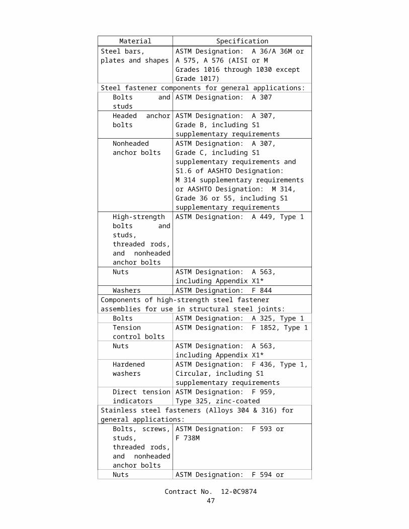
admixture until the mass of cement in the cement weigh hopper is within the tolerances specified in Section 90 -5.02, "Proportioning Devices."
• The discharge gate on the cement and mineral admixture hoppers or the cement plus mineral admixture hopper shall be designed to permit regulating the flow of cement, mineral admixture, or cement plus mineral admixture into the aggregate as directed by the Engineer.
• When separate weigh boxes are used for each size of aggregate, the discharge gates shall permit regulating the flow of each size of aggregate as directed by the Engineer.
• Material discharged from the several bins shall be controlled by gates or by mechanical conveyors. The means of withdrawal from the several bins, and of discharge from the weigh box, shall be interlocked so that not more than one bin can discharge at a time, and so that the weigh box cannot be tripped until the required quantity from each of the several bins has been deposited therein. Should a separate weigh box be used for each size of aggregate, all may be operated and discharged simultaneously.
• When the discharge from the several bins is controlled by gates, each gate shall be actuated automatically so that the required mass is discharged into the weigh box, after which the gate shall automatically close and lock.
• The automatic weighing system shall be designed so that all proportions required may be set on the weighing controller at the same time.
90-6 MIXING AND TRANSPORTING
90-6.01 GENERAL• Concrete shall be mixed in mechanically operated mixers, except that when permitted by the Engineer, batches not
exceeding 0.25 m3 may be mixed by hand methods in conformance with the provisions in Section 90-6.05, "Hand-Mixing."• Equipment having components made of aluminum or magnesium alloys that would have contact with plastic
concrete during mixing, transporting, or pumping of portland cement concrete shall not be used.• Concrete shall be homogeneous and thoroughly mixed, and there shall be no lumps or evidence of undispersed
cement, mineral admixture, or cement plus mineral admixture.• Uniformity of concrete mixtures will be determined by differences in penetration as determined by California
Test 533, or slump as determined by ASTM Designation: C 143, and by variations in the proportion of coarse aggregate as determined by California Test 529.
• When the mix design specifies a penetration value, the difference in penetration, determined by comparing penetration tests on 2 samples of mixed concrete from the same batch or truck mixer load, shall not exceed 10 mm. When the mix design specifies a slump value, the difference in slump, determined by comparing slump tests on 2 samples of mixed concrete from the same batch or truck mixer load, shall not exceed the values given in the table below. Variation in the proportion of coarse aggregate will be determined by comparing the results of tests of 2 samples of mixed concrete from the same batch or truck mixer load and the difference between the 2 results shall not exceed 100 kg per cubic meter of concrete.
Average Slump Maximum Permissible DifferenceLess than 100-mm 25-mm100-mm to 150-mm 38-mmGreater than 150-mm to 225-mm 50-mm
• The Contractor, at the Contractor's expense, shall furnish samples of the freshly mixed concrete and provide satisfactory facilities for obtaining the samples.
90-6.02 MACHINE MIXING• Concrete mixers may be of the revolving drum or the revolving blade type, and the mixing drum or blades shall be
operated uniformly at the mixing speed recommended by the manufacturer. Mixers and agitators that have an accumulation of hard concrete or mortar shall not be used.
• The temperature of mixed concrete, immediately before placing, shall be not less than 10°C or more than 32°C. Aggregates and water shall be heated or cooled as necessary to produce concrete within these temperature limits. Neither aggregates nor mixing water shall be heated to exceed 65°C. If ice is used to cool the concrete, discharge of the mixer will not be permitted until all ice is melted.
• The batch shall be so charged into the mixer that some water will enter in advance of cementitious materials and aggregates. All water shall be in the drum by the end of the first one-fourth of the specified mixing time.
• Cementitious materials shall be batched and charged into the mixer by means that will not result either in loss of cementitious materials due to the effect of wind, in accumulation of cementitious materials on surfaces of conveyors or hoppers, or in other conditions that reduce or vary the required quantity of cementitious material in the concrete mixture.
Contract No. 12-0C987449
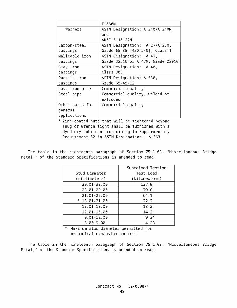
• Paving and stationary mixers shall be operated with an automatic timing device. The timing device and discharge mechanism shall be interlocked so that during normal operation no part of the batch will be discharged until the specified mixing time has elapsed.
• The total elapsed time between the intermingling of damp aggregates and all cementitious materials and the start of mixing shall not exceed 30 minutes.
• The size of batch shall not exceed the manufacturer's guaranteed capacity.• When producing concrete for pavement or base, suitable batch counters shall be installed and maintained in good
operating condition at jobsite batching plants and stationary mixers. The batch counters shall indicate the exact number of batches proportioned and mixed.
• Concrete shall be mixed and delivered to the jobsite by means of one of the following combinations of operations:
A. Mixed completely in a stationary mixer and the mixed concrete transported to the point of delivery in truck agitators or in non-agitating hauling equipment (central-mixed concrete).
B. Mixed partially in a stationary mixer, and the mixing completed in a truck mixer (shrink-mixed concrete).C. Mixed completely in a truck mixer (transit-mixed concrete).D. Mixed completely in a paving mixer.
• Agitators may be truck mixers operating at agitating speed or truck agitators. Each mixer and agitator shall have attached thereto in a prominent place a metal plate or plates on which is plainly marked the various uses for which the equipment is designed, the manufacturer's guaranteed capacity of the drum or container in terms of the volume of mixed concrete and the speed of rotation of the mixing drum or blades.
• Truck mixers shall be equipped with electrically or mechanically actuated revolution counters by which the number of revolutions of the drum or blades may readily be verified.
• When shrink-mixed concrete is furnished, concrete that has been partially mixed at a central plant shall be transferred to a truck mixer and all requirements for transit-mixed concrete shall apply. No credit in the number of revolutions at mixing speed shall be allowed for partial mixing in a central plant.
90-6.03 TRANSPORTING MIXED CONCRETE• Mixed concrete may be transported to the delivery point in truck agitators or truck mixers operating at the speed
designated by the manufacturer of the equipment as agitating speed, or in non-agitating hauling equipment, provided the consistency and workability of the mixed concrete upon discharge at the delivery point is suitable for adequate placement and consolidation in place, and provided the mixed concrete after hauling to the delivery point conforms to the provisions in Section 90-6.01, "General."
• Truck agitators shall be loaded not to exceed the manufacturer's guaranteed capacity and shall maintain the mixed concrete in a thoroughly mixed and uniform mass during hauling.
• Bodies of non-agitating hauling equipment shall be constructed so that leakage of the concrete mix, or any part thereof, will not occur at any time.
• Concrete hauled in open-top vehicles shall be protected during hauling against rain or against exposure to the sun for more than 20 minutes when the ambient temperature exceeds 24°C.
• No additional mixing water shall be incorporated into the concrete during hauling or after arrival at the delivery point, unless authorized by the Engineer. If the Engineer authorizes additional water to be incorporated into the concrete, the drum shall be revolved not less than 30 revolutions at mixing speed after the water is added and before discharge is commenced.
• The rate of discharge of mixed concrete from truck mixer-agitators shall be controlled by the speed of rotation of the drum in the discharge direction with the discharge gate fully open.
• When a truck mixer or agitator is used for transporting concrete to the delivery point, discharge shall be completed within 1.5 hours or before 250 revolutions of the drum or blades, whichever occurs first, after the introduction of the cement to the aggregates. Under conditions contributing to quick stiffening of the concrete, or when the temperature of the concrete is 30°C or above, the time allowed may be less than 1.5 hours.
• When non-agitating hauling equipment is used for transporting concrete to the delivery point, discharge shall be completed within one hour after the addition of the cement to the aggregates. Under conditions contributing to quick stiffening of the concrete, or when the temperature of the concrete is 30°C or above, the time between the introduction of cement to the aggregates and discharge shall not exceed 45 minutes.
• Each load of concrete delivered at the jobsite shall be accompanied by a weighmaster certificate showing the mix identification number, non-repeating load number, date and time at which the materials were batched, the total amount of water added to the load, and for transit-mixed concrete, the reading of the revolution counter at the time the truck mixer is charged with cement. This weighmaster certificate shall also show the actual scale masses (kilograms) for the ingredients batched. Theoretical or target batch masses shall not be used as a substitute for actual scale masses.
Contract No. 12-0C987450
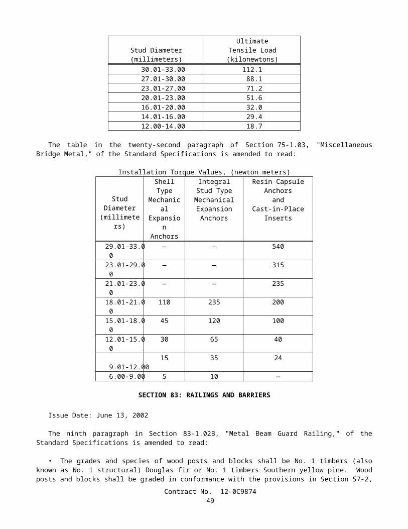
• Weighmaster certificates shall be provided in printed form, or if approved by the Engineer, the data may be submitted in electronic media. Electronic media shall be presented in a tab-delimited format on a 90 mm diskette with a capacity of at least 1.4 megabytes. Captured data, for the ingredients represented by each batch shall be "line feed, carriage return" (LFCR) and "one line, separate record" with allowances for sufficient fields to satisfy the amount of data required by these specifications.
• The Contractor may furnish a weighmaster certificate accompanied by a separate certificate that lists the actual batch masses or measurements for a load of concrete provided that both certificates are imprinted with the same non-repeating load number that is unique to the contract and delivered to the jobsite with the load.
• Weighmaster certificates furnished by the Contractor shall conform to the provisions in Section 9-1.01, "Measurement of Quantities."
90-6.04 TIME OR AMOUNT OF MIXING• Mixing of concrete in paving or stationary mixers shall continue for the required mixing time after all ingredients,
except water and admixture, if added with the water, are in the mixing compartment of the mixer before any part of the batch is released. Transfer time in multiple drum mixers shall not be counted as part of the required mixing time.
• The required mixing time, in paving or stationary mixers, of concrete used for concrete structures, except minor structures, shall be not less than 90 seconds or more than 5 minutes, except that when directed by the Engineer in writing, the requirements of the following paragraph shall apply.
• The required mixing time, in paving or stationary mixers, except as provided in the preceding paragraph, shall be not less than 50 seconds or more than 5 minutes.
• The minimum required revolutions at the mixing speed for transit-mixed concrete shall not be less than that recommended by the mixer manufacturer, but in no case shall the number of revolutions be less than that required to consistently produce concrete conforming to the provisions for uniformity in Section 90-6.01, "General."
90-6.05 HAND-MIXING• Hand-mixed concrete shall be made in batches of not more than 0.25 m3 and shall be mixed on a watertight, level
platform. The proper amount of coarse aggregate shall be measured in measuring boxes and spread on the platform and the fine aggregate shall be spread on this layer, the 2 layers being not more than 0.3 meters in total depth. On this mixture shall be spread the dry cement and mineral admixture and the whole mass turned no fewer than 2 times dry; then sufficient clean water shall be added, evenly distributed, and the whole mass again turned no fewer than 3 times, not including placing in the carriers or forms.
90-6.06 AMOUNT OF WATER AND PENETRATION• The amount of water used in concrete mixes shall be regulated so that the penetration of the concrete as determined
by California Test 533 or the slump of the concrete as determined by ASTM Designation: C 143 is within the "Nominal" values shown in the following table. When the penetration or slump of the concrete is found to exceed the nominal values listed, the mixture of subsequent batches shall be adjusted to reduce the penetration or slump to a value within the nominal range shown. Batches of concrete with a penetration or slump exceeding the maximum values listed shall not be used in the work. When Type F or Type G chemical admixtures are added to the mix, the penetration requirements shall not apply and the slump shall not exceed 225 mm after the chemical admixtures are added.
Type of Work Nominal MaximumPenetration Slump Penetration Slump
(mm) (mm) (mm) (mm)Concrete Pavement 0-25 — 40 —Non-reinforced concrete facilities 0-35 — 50 —Reinforced concrete structures
Sections over 300-mm thick 0-35 — 65 —Sections 300-mm thick or less 0-50 — 75 —
Concrete placed under water — 150-200 — 225Cast-in-place concrete piles 65-90 130-180 100 200
• The amount of free water used in concrete shall not exceed 183 kg/m3, plus 20 kg for each required 100 kg of cementitious material in excess of 325 kg/m3.
• The term free water is defined as the total water in the mixture minus the water absorbed by the aggregates in reaching a saturated surface-dry condition.
Contract No. 12-0C987451
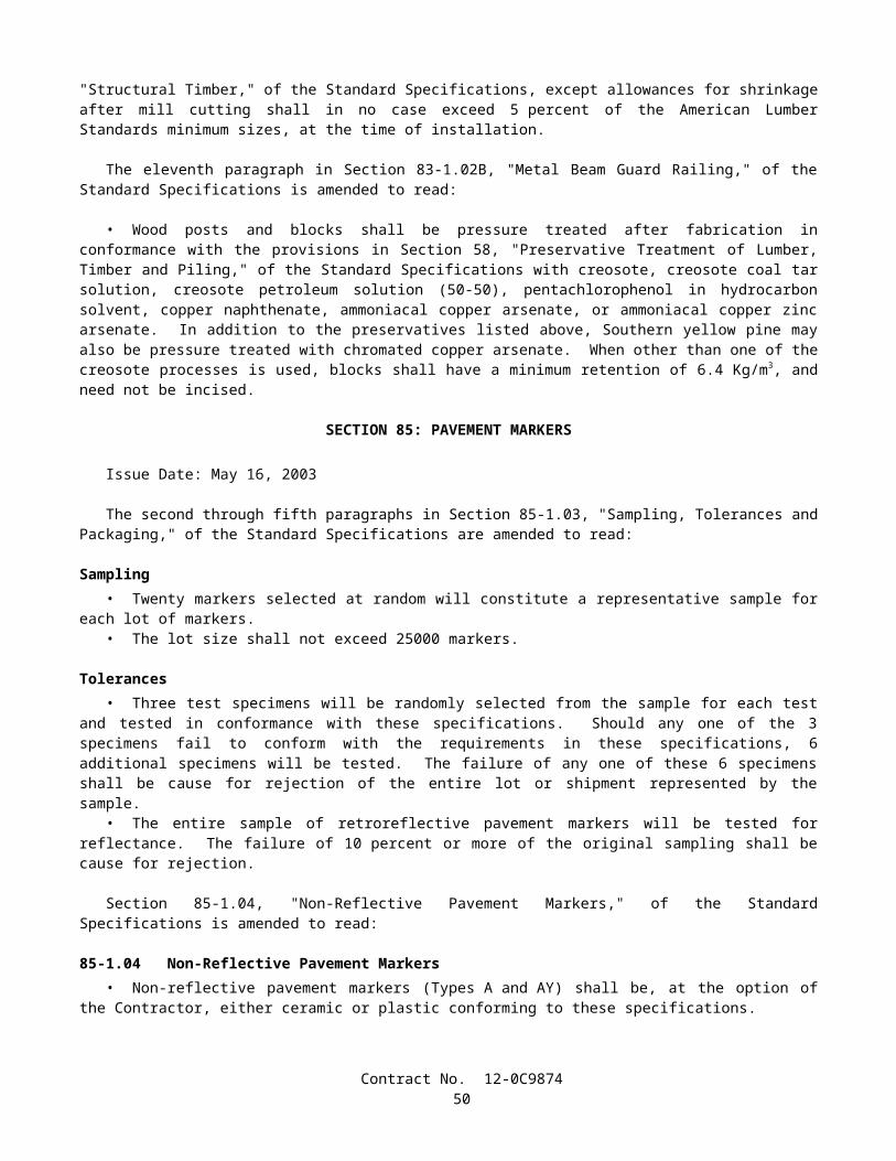
• Where there are adverse or difficult conditions that affect the placing of concrete, the above specified penetration and free water content limitations may be exceeded providing the Contractor is granted permission by the Engineer in writing to increase the cementitious material content per cubic meter of concrete. The increase in water and cementitious material shall be at a ratio not to exceed 30 kg of water per added 100 kg of cementitious material per cubic meter. The cost of additional cementitious material and water added under these conditions shall be at the Contractor’s expense and no additional compensation will be allowed therefor.
• The equipment for supplying water to the mixer shall be constructed and arranged so that the amount of water added can be measured accurately. Any method of discharging water into the mixer for a batch shall be accurate within 1.5 percent of the quantity of water required to be added to the mix for any position of the mixer. Tanks used to measure water shall be designed so that water cannot enter while water is being discharged into the mixer and discharge into the mixer shall be made rapidly in one operation without dribbling. All equipment shall be arranged so as to permit checking the amount of water delivered by discharging into measured containers.
90-7 CURING CONCRETE
90-7.01 METHODS OF CURING• Newly placed concrete shall be cured by the methods specified in this Section 90-7.01 and the special provisions.
90-7.01A Water Method• The concrete shall be kept continuously wet by the application of water for a minimum curing period of 7 days after
the concrete has been placed.• When a curing medium consisting of cotton mats, rugs, carpets, or earth or sand blankets is to be used to retain the
moisture, the entire surface of the concrete shall be kept damp by applying water with a nozzle that so atomizes the flow that a mist and not a spray is formed, until the surface of the concrete is covered with the curing medium. The moisture from the nozzle shall not be applied under pressure directly upon the concrete and shall not be allowed to accumulate on the concrete in a quantity sufficient to cause a flow or wash the surface. At the expiration of the curing period, the concrete surfaces shall be cleared of all curing mediums.
• When concrete bridge decks and flat slabs are to be cured without the use of a curing medium, the entire surface of the bridge deck or slab shall be kept damp by the application of water with an atomizing nozzle as specified in the preceding paragraph, until the concrete has set, after which the entire surface of the concrete shall be sprinkled continuously with water for a period of not less than 7 days.
90-7.01B Curing Compound Method• Surfaces of the concrete that are exposed to the air shall be sprayed uniformly with a curing compound.• Curing compounds to be used shall be as follows:
1. Pigmented curing compound conforming to the requirements in ASTM Designation: C 309, Type 2, Class B, except the resin type shall be poly-alpha-methylstyrene.
2. Pigmented curing compound conforming to the requirements in ASTM Designation: C 309, Type 2, Class B.3. Pigmented curing compound conforming to the requirements in ASTM Designation: C 309, Type 2, Class A.4. Non-pigmented curing compound conforming to the requirements in ASTM Designation: C 309, Type 1, Class B.5. Non-pigmented curing compound conforming to the requirements in ASTM Designation: C 309, Type 1, Class A.6. Non-pigmented curing compound with fugitive dye conforming to the requirements in ASTM Designation: C 309,
Type 1-D, Class A.
• The infrared scan for the dried vehicle from curing compound (1) shall match the infrared scan on file at the Transportation Laboratory.
• The loss of water for each type of curing compound, when tested in conformance with the requirements in California Test 534, shall not be more than 0.15-kg/m2 in 24 hours.
• The curing compound to be used will be specified elsewhere in these specifications or in the special provisions.• When the use of curing compound is required or permitted elsewhere in these specifications or in the special
provisions and no specific kind is specified, any of the curing compounds listed above may be used.• Curing compound shall be applied at a nominal rate of 3.7 m2/L, unless otherwise specified.• At any point, the application rate shall be within ±1.2 m2/L of the nominal rate specified, and the average application
rate shall be within ±0.5 m2/L of the nominal rate specified when tested in conformance with the requirements in California Test 535. Runs, sags, thin areas, skips, or holidays in the applied curing compound shall be evidence that the application is not satisfactory.
Contract No. 12-0C987452
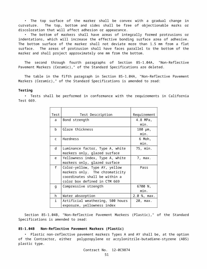
• Curing compounds shall be applied using power operated spray equipment. The power operated spraying equipment shall be equipped with an operational pressure gage and a means of controlling the pressure. Hand spraying of small and irregular areas that are not reasonably accessible to mechanical spraying equipment, in the opinion of the Engineer, may be permitted.
• The curing compound shall be applied to the concrete following the surface finishing operation, immediately before the moisture sheen disappears from the surface, but before any drying shrinkage or craze cracks begin to appear. In the event of any drying or cracking of the surface, application of water with an atomizing nozzle as specified in Section 90-7.01A, "Water Method," shall be started immediately and shall be continued until application of the compound is resumed or started; however, the compound shall not be applied over any resulting freestanding water. Should the film of compound be damaged from any cause before the expiration of 7 days after the concrete is placed in the case of structures and 72 hours in the case of pavement, the damaged portion shall be repaired immediately with additional compound.
• At the time of use, compounds containing pigments shall be in a thoroughly mixed condition with the pigment uniformly dispersed throughout the vehicle. A paddle shall be used to loosen all settled pigment from the bottom of the container, and a power driven agitator shall be used to disperse the pigment uniformly throughout the vehicle.
• Agitation shall not introduce air or other foreign substance into the curing compound.• The manufacturer shall include in the curing compound the necessary additives for control of sagging, pigment
settling, leveling, de-emulsification, or other requisite qualities of a satisfactory working material. Pigmented curing compounds shall be manufactured so that the pigment does not settle badly, does not cake or thicken in the container, and does not become granular or curdled. Settlement of pigment shall be a thoroughly wetted, soft, mushy mass permitting the complete and easy vertical penetration of a paddle. Settled pigment shall be easily redispersed, with minimum resistance to the sideways manual motion of the paddle across the bottom of the container, to form a smooth uniform product of the proper consistency.
• Curing compounds shall remain sprayable at temperatures above 4°C and shall not be diluted or altered after manufacture.
• The curing compound shall be packaged in clean 1040-L totes, 210-L barrelsor 19-L pails shall be supplied from a suitable storage tank located at the jobsite. The containers shall comply with
"Title 49, Code of Federal Regulations, Hazardous Materials Regulations." The 1040-L totes and the 210-L barrels shall have removable lids and airtight fasteners. The 19-L pails shall be round and have standard full open head and bail. Lids with bungholes shall not be permitted. Settling or separation of solids in containers, except tanks, must be completely redispersed with low speed mixing prior to use, in conformance with these specifications and the manufacturer's recommendations. Mixing shall be accomplished either manually by use of a paddle or by use of a mixing blade driven by a drill motor, at low speed. Mixing blades shall be the type used for mixing paint. On site storage tanks shall be kept clean and free of contaminants. Each tank shall have a permanent system designed to completely redisperse settled material without introducing air or other foreign substances.
• Steel containers and lids shall be lined with a coating that will prevent destructive action by the compound or chemical agents in the air space above the compound. The coating shall not come off the container or lid as skins. Containers shall be filled in a manner that will prevent skinning. Plastic containers shall not react with the compound.
• Each container shall be labeled with the manufacturer's name, kind of curing compound, batch number, volume, date of manufacture, and volatile organic compound (VOC) content. The label shall also warn that the curing compound containing pigment shall be well stirred before use. Precautions concerning the handling and the application of curing compound shall be shown on the label of the curing compound containers in conformance with the Construction Safety Orders and General Industry Safety Orders of the State of California.
• Containers of curing compound shall be labeled to indicate that the contents fully comply with the rules and regulations concerning air pollution control in the State of California.
• When the curing compound is shipped in tanks or tank trucks, a shipping invoice shall accompany each load. The invoice shall contain the same information as that required herein for container labels.
• Curing compound will be sampled by the Engineer at the source of supply or at the jobsite or at both locations.• Curing compound shall be formulated so as to maintain the specified properties for a minimum of one year. The
Engineer may require additional testing before use to determine compliance with these specifications if the compound has not been used within one year or whenever the Engineer has reason to believe the compound is no longer satisfactory.
• Tests will be conducted in conformance with the latest ASTM test methods and methods in use by the Transportation Laboratory.
90-7.01C Waterproof Membrane Method• The exposed finished surfaces of concrete shall be sprayed with water, using a nozzle that so atomizes the flow that
a mist and not a spray is formed, until the concrete has set, after which the curing membrane shall be placed. The curing membrane shall remain in place for a period of not less than 72 hours.
Contract No. 12-0C987453
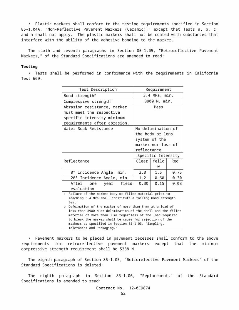
• Sheeting material for curing concrete shall conform to the requirements in AASHTO Designation: M 171 for white reflective materials.
• The sheeting material shall be fabricated into sheets of such width as to provide a complete cover for the entire concrete surface. Joints in the sheets shall be securely cemented together in such a manner as to provide a waterproof joint. The joint seams shall have a minimum lap of 100 mm.
• The sheets shall be securely weighted down by placing a bank of earth on the edges of the sheets or by other means satisfactory to the Engineer.
• Should any portion of the sheets be broken or damaged before the expiration of 72 hours after being placed, the broken or damaged portions shall be immediately repaired with new sheets properly cemented into place.
• Sections of membrane that have lost their waterproof qualities or have been damaged to such an extent as to render them unfit for curing the concrete shall not be used.
90-7.01D Forms-In-Place Method• Formed surfaces of concrete may be cured by retaining the forms in place. The forms shall remain in place for a
minimum period of 7 days after the concrete has been placed, except that for members over 0.5-m in least dimension the forms shall remain in place for a minimum period of 5 days.
• Joints in the forms and the joints between the end of forms and concrete shall be kept moisture tight during the curing period. Cracks in the forms and cracks between the forms and the concrete shall be resealed by methods subject to the approval of the Engineer.
90-7.02 CURING PAVEMENT• The entire exposed area of the pavement, including edges, shall be cured by the waterproof membrane method, or
curing compound method using curing compound (1) or (2) as the Contractor may elect. Should the side forms be removed before the expiration of 72 hours following the start of curing, the exposed pavement edges shall also be cured. If the pavement is cured by means of the curing compound method, the sawcut and all portions of the curing compound that have been disturbed by sawing operations shall be restored by spraying with additional curing compound.
• Curing shall commence as soon as the finishing process provided in Section 40-1.10, "Final Finishing," has been completed. The method selected shall conform to the provisions in Section 90-7.01, "Methods of Curing."
• When the curing compound method is used, the compound shall be applied to the entire pavement surface by mechanical sprayers. Spraying equipment shall be of the fully atomizing type equipped with a tank agitator that provides for continual agitation of the curing compound during the time of application. The spray shall be adequately protected against wind, and the nozzles shall be so oriented or moved mechanically transversely as to result in the minimum specified rate of coverage being applied uniformly on exposed faces. Hand spraying of small and irregular areas, and areas inaccessible to mechanical spraying equipment, in the opinion of the Engineer, will be permitted. When the ambient air temperature is above 15°C, the Contractor shall fog the surface of the concrete with a fine spray of water as specified in Section 90 -7.01A, "Water Method." The surface of the pavement shall be kept moist between the hours of 10:00 a.m. and 4:30 p.m. on the day the concrete is placed. However, the fogging done after the curing compound has been applied shall not begin until the compound has set sufficiently to prevent displacement. Fogging shall be discontinued if ordered in writing by the Engineer.
90-7.03 CURING STRUCTURES• Newly placed concrete for cast-in-place structures, other than highway bridge decks, shall be cured by the water
method, the forms-in-place method, or, as permitted herein, by the curing compound method, in conformance with the provisions in Section 90-7.01, "Methods of Curing."
• The curing compound method using a pigmented curing compound may be used on concrete surfaces of construction joints, surfaces that are to be buried underground, and surfaces where only Ordinary Surface Finish is to be applied and on which a uniform color is not required and that will not be visible from a public traveled way. If the Contractor elects to use the curing compound method on the bottom slab of box girder spans, the curing compound shall be curing compound (1).
• The top surface of highway bridge decks shall be cured by both the curing compound method and the water method. The curing compound shall be curing compound (1).
• Concrete surfaces of minor structures, as defined in Section 51-1.02, "Minor Structures," shall be cured by the water method, the forms-in-place method or the curing compound method.
• When deemed necessary by the Engineer during periods of hot weather, water shall be applied to concrete surfaces being cured by the curing compound method or by the forms-in-place method, until the Engineer determines that a cooling effect is no longer required. Application of water for this purpose will be paid for as extra work as provided in Section 4-1.03D, "Extra Work."
Contract No. 12-0C987454

90-7.04 CURING PRECAST CONCRETE MEMBERS• Precast concrete members shall be cured in conformance with any of the methods specified in Section 90-7.01,
"Methods of Curing." Curing shall be provided for the minimum time specified for each method or until the concrete reaches its design strength, whichever is less. Steam curing may also be used for precast members and shall conform to the following provisions:
A. After placement of the concrete, members shall be held for a minimum 4-hour presteaming period. If the ambient air temperature is below 10°C, steam shall be applied during the presteaming period to hold the air surrounding the member at a temperature between 10°C and 32°C.
B. To prevent moisture loss on exposed surfaces during the presteaming period, members shall be covered as soon as possible after casting or the exposed surfaces shall be kept wet by fog spray or wet blankets.
C. Enclosures for steam curing shall allow free circulation of steam about the member and shall be constructed to contain the live steam with a minimum moisture loss. The use of tarpaulins or similar flexible covers will be permitted, provided they are kept in good repair and secured in such a manner as to prevent the loss of steam and moisture.
D. Steam at the jets shall be at low pressure and in a saturated condition. Steam jets shall not impinge directly on the concrete, test cylinders, or forms. During application of the steam, the temperature rise within the enclosure shall not exceed 22°C per hour. The curing temperature throughout the enclosure shall not exceed 65°C and shall be maintained at a constant level for a sufficient time necessary to develop the required transfer strength. Control cylinders shall be covered to prevent moisture loss and shall be placed in a location where temperature is representative of the average temperature of the enclosure.
E. Temperature recording devices that will provide an accurate, continuous, permanent record of the curing temperature shall be provided. A minimum of one temperature recording device per 60 m of continuous bed length will be required for checking temperature.
F. Members in pretension beds shall be detensioned immediately after the termination of steam curing while the concrete and forms are still warm, or the temperature under the enclosure shall be maintained above 15°C until the stress is transferred to the concrete.
G. Curing of precast concrete will be considered completed after termination of the steam curing cycle.
90-7.05 CURING PRECAST PRESTRESSED CONCRETE PILES• Newly placed concrete for precast prestressed concrete piles shall be cured in conformance with the provisions in
Section 90-7.04, "Curing Precast Concrete Members," except that piles with a class designation ending in C (corrosion resistant) shall be cured as follows:
A. Piles shall be either steam cured or water cured. If water curing is used, the piles shall be kept continuously wet by the application of water in conformance with the provisions in Section 90-7.01A, "Water Method."
B. If steam curing is used, the steam curing provisions in Section 90-7.04, "Curing Precast Concrete Members," shall apply except that the piles shall be kept continuously wet for their entire length for a period of not less than 3 days, including the holding and steam curing periods.
90-7.06 CURING SLOPE PROTECTION• Concrete slope protection shall be cured in conformance with any of the methods specified in Section 90-7.01,
"Methods of Curing."• Concreted-rock slope protection shall be cured in conformance with any of the methods specified in Section
90-7.01, "Methods of Curing," or with a blanket of earth kept wet for 72 hours, or by sprinkling with a fine spray of water every 2 hours during the daytime for a period of 3 days.
90-7.07 CURING MISCELLANEOUS CONCRETE WORK• Exposed surfaces of curbs shall be cured by pigmented curing compounds as specified in Section 90-7.01B, "Curing
Compound Method."• Concrete sidewalks, gutter depressions, island paving, curb ramps, driveways, and other miscellaneous concrete
areas shall be cured in conformance with any of the methods specified in Section 90-7.01, "Methods of Curing."• Shotcrete shall be cured for at least 72 hours by spraying with water, or by a moist earth blanket, or by any of the
methods provided in Section 90-7.01, "Methods of Curing."• Mortar and grout shall be cured by keeping the surface damp for 3 days.
Contract No. 12-0C987455
• After placing, the exposed surfaces of sign structure foundations, including pedestal portions, if constructed, shall be cured for at least 72 hours by spraying with water, or by a moist earth blanket, or by any of the methods provided in Section 90-7.01, "Methods of Curing."
90-8 PROTECTING CONCRETE
90-8.01 GENERAL• In addition to the provisions in Section 7-1.16, "Contractor's Responsibility for the Work and Materials," the
Contractor shall protect concrete as provided in this Section 90-8.• Concrete shall not be placed on frozen or ice-coated ground or subgrade nor on ice-coated forms, reinforcing steel,
structural steel, conduits, precast members, or construction joints.• Under rainy conditions, placing of concrete shall be stopped before the quantity of surface water is sufficient to
damage surface mortar or cause a flow or wash of the concrete surface, unless the Contractor provides adequate protection against damage.
• Concrete that has been frozen or damaged by other causes, as determined by the Engineer, shall be removed and replaced by the Contractor at the Contractor's expense.
90-8.02 PROTECTING CONCRETE STRUCTURES• Structure concrete and shotcrete used as structure concrete shall be maintained at a temperature of not less than 7°C
for 72 hours after placing and at not less than 4°C for an additional 4 days. When required by the Engineer, the Contractor shall submit a written outline of the proposed methods for protecting the concrete.
90-8.03 PROTECTING CONCRETE PAVEMENT• Pavement concrete shall be maintained at a temperature of not less than 4°C for 72 hours. When required by the
Engineer, the Contractor shall submit a written outline of the proposed methods for protecting the concrete.• Except as provided in Section 7-1.08, "Public Convenience," the Contractor shall protect concrete pavement against
construction and other activities that abrade, scar, discolor, reduce texture depth, lower coefficient of friction, or otherwise damage the surface. Stockpiling, drifting, or excessive spillage of soil, gravel, petroleum products, and concrete or asphalt mixes on the surface of concrete pavement is prohibited unless otherwise specified in these specifications, the special provisions or permitted by the Engineer.
• When ordered by the Engineer or shown on the plans or specified in the special provisions, pavement crossings shall be constructed for the convenience of public traffic. The material and work necessary for the construction of the crossings, and their subsequent removal and disposal, will be paid for at the contract unit prices for the items of work involved and if there are no contract items for the work involved, payment for pavement crossings will be made by extra work as provided in Section 4-1.03D, "Extra Work.". Where public traffic will be required to cross over the new pavement, Type III portland cement may be used in concrete, if permitted in writing by the Engineer. The pavement may be opened to traffic as soon as the concrete has developed a modulus of rupture of 3.8 MPa. The modulus of rupture will be determined by California Test 523.
• No traffic or Contractor's equipment, except as hereinafter provided, will be permitted on the pavement before a period of 10 days has elapsed after the concrete has been placed, nor before the concrete has developed a modulus of rupture of at least 3.8 MPa. Concrete that fails to attain a modulus of rupture of 3.8 MPa within 10 days shall not be opened to traffic until directed by the Engineer.
• Equipment for sawing weakened plane joints will be permitted on the pavement as specified in Section 40-1.08B, "Weakened Plane Joints."
• When requested in writing by the Contractor, the tracks on one side of paving equipment will be permitted on the pavement after a modulus of rupture of 2.4 MPa has been attained, provided that:
A. Unit pressure exerted on the pavement by the paver shall not exceed 135 kPa;B. Tracks with cleats, grousers, or similar protuberances shall be modified or shall travel on planks or equivalent
protective material, so that the pavement is not damaged; andC. No part of the track shall be closer than 0.3-m from the edge of pavement.
• In case of visible cracking of, or other damage to the pavement, operation of the paving equipment on the pavement shall be immediately discontinued.
• Damage to the pavement resulting from early use of pavement by the Contractor's equipment as provided above shall be repaired by the Contractor at the Contractor's expense.
Contract No. 12-0C987456
• The State will furnish the molds and machines for testing the concrete for modulus of rupture, and the Contractor, at the Contractor's expense, shall furnish the material and whatever labor the Engineer may require.
90-9 COMPRESSIVE STRENGTH
90-9.01 GENERAL• Concrete compressive strength requirements consist of a minimum strength that shall be attained before various
loads or stresses are applied to the concrete and, for concrete designated by strength, a minimum strength at the age of 28 days or at the age otherwise allowed in Section 90-1.01, "Description." The various strengths required are specified in these specifications or the special provisions or are shown on the plans.
• The compressive strength of concrete will be determined from test cylinders that have been fabricated from concrete sampled in conformance with the requirements of California Test 539. Test cylinders will be molded and initially field cured in conformance with California Test 540. Test cylinders will be cured and tested after receipt at the testing laboratory in conformance with the requirements of California Test 521. A strength test shall consist of the average strength of 2 cylinders fabricated from material taken from a single load of concrete, except that, if any cylinder should show evidence of improper sampling, molding, or testing, that cylinder shall be discarded and the strength test shall consist of the strength of the remaining cylinder.
• When concrete compressive strength is specified as a prerequisite to applying loads or stresses to a concrete structure or member, test cylinders for other than steam cured concrete will be cured in conformance with Method 1 of California Test 540. The compressive strength of concrete determined for these purposes will be evaluated on the basis of individual tests.
• When concrete is designated by 28-day compressive strength rather than by cementitious material content, the concrete strength to be used as a basis for acceptance of other than steam cured concrete will be determined from cylinders cured in conformance with Method 1 of California Test 540. If the result of a single compressive strength test at the maximum age specified or allowed is below the specified strength but is 95 percent or more of the specified strength, the Contractor shall, at the Contractor’s expense, make corrective changes, subject to approval of the Engineer, in the mix proportions or in the concrete fabrication procedures, before placing additional concrete, and shall pay to the State $14 for each in-place cubic meter of concrete represented by the deficient test. If the result of a single compressive strength test at the maximum age specified or allowed is below 95 percent of the specified strength, but is 85 percent or more of the specified strength, the Contractor shall make the corrective changes specified above, and shall pay to the State $20 for each in place cubic meter of concrete represented by the deficient test. In addition, such corrective changes shall be made when the compressive strength of concrete tested at 7 days indicates, in the judgment of the Engineer, that the concrete will not attain the required compressive strength at the maximum age specified or allowed. Concrete represented by a single test that indicates a compressive strength of less than 85 percent of the specified 28-day compressive strength will be rejected in conformance with the provisions in Section 6-1.04, "Defective Materials."
• If the test result indicates that the compressive strength at the maximum curing age specified or allowed is below the specified strength, but is 85 percent or more of the specified strength, payments to the State as required above shall be made, unless the Contractor, at the Contractor’s expense, obtains and submits evidence acceptable to the Engineer that the strength of the concrete placed in the work meets or exceeds the specified 28-day compressive strength. If the test result indicates a compressive strength at the maximum curing age specified or allowed below 85 percent, the concrete represented by that test will be rejected, unless the Contractor, at the Contractor’s expense, obtains and submits evidence acceptable to the Engineer that the strength and quality of the concrete placed in the work are acceptable. If the evidence consists of tests made on cores taken from the work, the cores shall be obtained and tested in conformance with the requirements in ASTM Designation: C 42.
• No single compressive strength test shall represent more than 250 m3.• When a precast concrete member is steam cured, the compressive strength of the concrete will be determined from
test cylinders that have been handled and stored in conformance with Method 3 of California Test 540. The compressive strength of steam cured concrete will be evaluated on the basis of individual tests representing specific portions of production. When the concrete is designated by 28-day compressive strength rather than by cementitious material content, the concrete shall be considered to be acceptable whenever its compressive strength reaches the specified 28-day compressive strength provided that strength is reached in not more than the maximum number of days specified or allowed after the member is cast.
• When concrete is specified by compressive strength, prequalification of materials, mix proportions, mixing equipment, and procedures proposed for use will be required prior to placement of the concrete. Prequalification shall be accomplished by the submission of acceptable certified test data or trial batch reports by the Contractor. Prequalification data shall be based on the use of materials, mix proportions, mixing equipment, procedures, and size of batch proposed for use in the work.
Contract No. 12-0C987457

• Certified test data, in order to be acceptable, shall indicate that not less than 90 percent of at least 20 consecutive tests exceed the specified strength at the maximum number of cure days specified or allowed, and none of those tests are less than 95 percent of specified strength. Strength tests included in the data shall be the most recent tests made on concrete of the proposed mix design and all shall have been made within one year of the proposed use of the concrete.
• Trial batch test reports, in order to be acceptable, shall indicate that the average compressive strength of 5 consecutive concrete cylinders, taken from a single batch, at not more than 28 days (or the maximum age allowed) after molding shall be at least 4 MPa greater than the specified 28-day compressive strength, and no individual cylinder shall have a strength less than the specified strength at the maximum age specified or allowed. Data contained in the report shall be from trial batches that were produced within one year of the proposed use of specified strength concrete in the project. Whenever air-entrainment is required, the air content of trial batches shall be equal to or greater than the air content specified for the concrete without reduction due to tolerances.
• Tests shall be performed in conformance with either the appropriate California Test methods or the comparable ASTM test methods. Equipment employed in testing shall be in good condition and shall be properly calibrated. If the tests are performed during the life of the contract, the Engineer shall be notified sufficiently in advance of performing the tests in order to witness the test procedures.
• The certified test data and trial batch test reports shall include the following information:
A. Date of mixing.B. Mixing equipment and procedures used.C. The size of batch in cubic meters and the mass, type, and source of all ingredients used.D. Penetration of the concrete.E. The air content of the concrete if an air-entraining admixture is used.F. The age at time of testing and strength of all concrete cylinders tested.
• Certified test data and trial batch test reports shall be signed by an official of the firm that performed the tests.• When approved by the Engineer, concrete from trial batches may be used in the work at locations where concrete of
a lower quality is required and the concrete will be paid for as the type or class of concrete required at that location.• After materials, mix proportions, mixing equipment, and procedures for concrete have been prequalified for use,
additional prequalification by testing of trial batches will be required prior to making changes that, in the judgment of the Engineer, could result in a strength of concrete below that specified.
• The Contractor’s attention is directed to the time required to test trial batches and the Contractor shall be responsible for production of trial batches at a sufficiently early date so that the progress of the work is not delayed.
• When precast concrete members are manufactured at the plant of an established manufacturer of precast concrete members, the mix proportions of the concrete shall be determined by the Contractor, and a trial batch and prequalification of the materials, mix proportions, mixing equipment, and procedures will not be required.
90-10 MINOR CONCRETE
90-10.01 GENERAL• Concrete for minor structures, slope paving, curbs, sidewalks and other concrete work, when designated as minor
concrete on the plans, in the specifications, or in the contract item, shall conform to the provisions specified herein.• The Engineer, at the Engineer's discretion, will inspect and test the facilities, materials and methods for producing
the concrete to ensure that minor concrete of the quality suitable for use in the work is obtained.
90-10.02 MATERIALS• Minor concrete shall conform to the following requirements:
90-10.02A Cementitious Material• Cementitious material shall conform to the provisions in Section 90-1.01, "Description."
90-10.02B Aggregate• Aggregate shall be clean and free from deleterious coatings, clay balls, roots, and other extraneous materials.• The Contractor shall submit to the Engineer for approval, a grading of the combined aggregate proposed for use in
the minor concrete. After acceptance of the grading, aggregate furnished for minor concrete shall conform to that grading, unless a change is authorized in writing by the Engineer.
Contract No. 12-0C987458
• The Engineer may require the Contractor to furnish periodic test reports of the aggregate grading furnished. The maximum size of aggregate used shall be at the option of the Contractor, but in no case shall the maximum size be larger than 37.5 mm or smaller than 19 mm.
• The Engineer may waive, in writing, the gradation requirements in this Section 90-10.02B, if, in the Engineer's opinion, the furnishing of the gradation is not necessary for the type or amount of concrete work to be constructed.
90-10.02C Water• Water used for washing, mixing, and curing shall be free from oil, salts, and other impurities that would discolor or
etch the surface or have an adverse affect on the quality of the concrete.
90-10.02D Admixtures• The use of admixtures shall conform to the provisions in Section 90-4, "Admixtures."
90-10.03 PRODUCTION• Cementitious material, water, aggregate, and admixtures shall be stored, proportioned, mixed, transported, and
discharged in conformance with recognized standards of good practice that will result in concrete that is thoroughly and uniformly mixed, that is suitable for the use intended, and that conforms to requirements specified herein. Recognized standards of good practice are outlined in various industry publications such as are issued by American Concrete Institute, AASHTO, or the Department.
• The cementitious material content of minor concrete shall conform to the provisions in Section 90-1.01, "Description."
• The amount of water used shall result in a consistency of concrete conforming to the provisions in Section 90 -6.06, "Amount of Water and Penetration." Additional mixing water shall not be incorporated into the concrete during hauling or after arrival at the delivery point, unless authorized by the Engineer.
• Discharge of ready-mixed concrete from the transporting vehicle shall be made while the concrete is still plastic and before stiffening occurs. An elapsed time of 1.5 hours (one hour in non-agitating hauling equipment), or more than 250 revolutions of the drum or blades, after the introduction of the cementitious material to the aggregates, or a temperature of concrete of more than 32°C will be considered conditions contributing to the quick stiffening of concrete. The Contractor shall take whatever action is necessary to eliminate quick stiffening, except that the addition of water will not be permitted.
• The required mixing time in stationary mixers shall be not less than 50 seconds or more than 5 minutes.• The minimum required revolutions at mixing speed for transit-mixed concrete shall be not less than that
recommended by the mixer manufacturer, and shall be increased, if necessary, to produce thoroughly and uniformly mixed concrete.
• Each load of ready-mixed concrete shall be accompanied by a weighmaster certificate that shall be delivered to the Engineer at the discharge location of the concrete, unless otherwise directed by the Engineer. The weighmaster certificate shall be clearly marked with the date and time of day when the load left the batching plant and, if hauled in truck mixers or agitators, the time the mixing cycle started.
• A Certificate of Compliance conforming to the provisions in Section 6–1.07, "Certificates of Compliance," shall be furnished to the Engineer, prior to placing minor concrete from a source not previously used on the contract, stating that minor concrete to be furnished meets contract requirements, including minimum cementitious material content specified.
90-10.04 CURING MINOR CONCRETE• Curing minor concrete shall conform to the provisions in Section 90-7, "Curing Concrete."
90-10.05 PROTECTING MINOR CONCRETE• Protecting minor concrete shall conform to the provisions in Section 90-8, "Protecting Concrete," except the
concrete shall be maintained at a temperature of not less than 4°C for 72 hours after placing.
90-10.06 MEASUREMENT AND PAYMENT• Minor concrete will be measured and paid for in conformance with the provisions specified in the various sections
of these specifications covering concrete construction when minor concrete is specified in the specifications, shown on the plans, or indicated by contract item in the Engineer's Estimate.
90-11 MEASUREMENT AND PAYMENT
Contract No. 12-0C987459
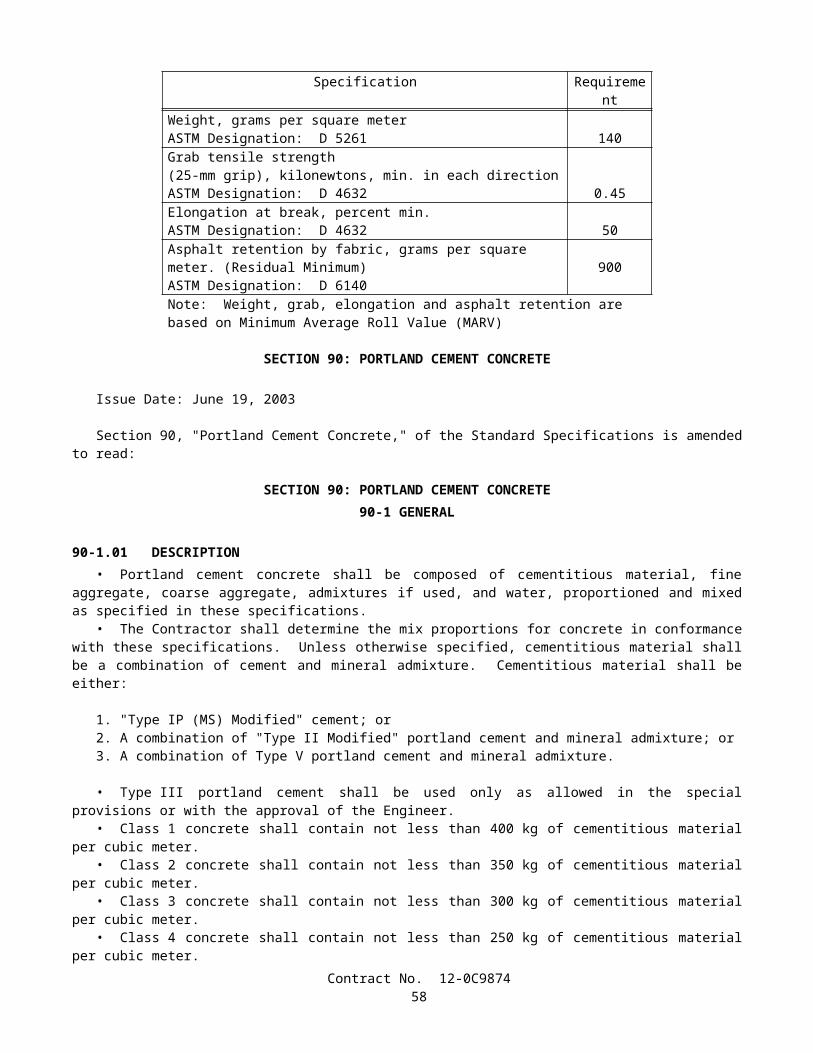
90-11.01 MEASUREMENT• Portland cement concrete will be measured in conformance with the provisions specified in the various sections of
these specifications covering construction requiring concrete.• When it is provided that concrete will be measured at the mixer, the volume in cubic meters shall be computed as
the total mass of the batch in kilograms divided by the density of the concrete in kilograms per cubic meter. The total mass of the batch shall be calculated as the sum of all materials, including water, entering the batch. The density of the concrete will be determined in conformance with the requirements in California Test 518.
90-11.02 PAYMENT• Portland cement concrete will be paid for in conformance with the provisions specified in the various sections of
these specifications covering construction requiring concrete.• Full compensation for furnishing and incorporating admixtures required by these specifications or the special
provisions will be considered as included in the contract prices paid for the concrete involved and no additional compensation will be allowed therefor.
• Should the Engineer order the Contractor to incorporate any admixtures in the concrete when their use is not required by these specifications or the special provisions, furnishing the admixtures and adding them to the concrete will be paid for as extra work as provided in Section 4-1.03D, "Extra Work."
• Should the Contractor use admixtures in conformance with the provisions in Section 90-4.05, "Optional Use of Chemical Admixtures," or Section 90-4.07, "Optional Use of Air-entraining Admixtures," or should the Contractor request and obtain permission to use other admixtures for the Contractor’s benefit, the Contractor shall furnish those admixtures and incorporate them into the concrete at the Contractor’s expense and no additional compensation will be allowed therefor.
END OF AMENDMENTS
SECTION 2. PROPOSAL REQUIREMENTS AND CONDITIONS2-1.01 GENERAL
The bidder's attention is directed to the provisions in Section 2, "Proposal Requirements and Conditions," of the Standard Specifications and these special provisions for the requirements and conditions which the bidder must observe in the preparation of the Proposal form and the submission of the bid.
In addition to the subcontractors required to be listed in conformance with Section 2-1.054, "Required Listing of Proposed Subcontractors," of the Standard Specifications, each proposal shall have listed therein the portion of work that will be performed by each subcontractor listed.
The Bidder's Bond form mentioned in the last paragraph in Section 2-1.07, "Proposal Guaranty," of the Standard Specifications will be found following the signature page of the Proposal.
Submit request for substitution of an "or equal" item, and the data substantiating the request to the Department of Transportation, District 12, 3347 Michelson Drive, Suite 100, Irvine, CA 92612-1692, Attn: CTO Desk - Construction Office, so that the request is received by the Department by close of business on the fourth day, not including Saturdays, Sundays and legal holidays, following bid opening.
In conformance with Public Contract Code Section 7106, a Noncollusion Affidavit is included in the Proposal. Signing the Proposal shall also constitute signature of the Noncollusion Affidavit.
The contractor, sub recipient or subcontractor shall not discriminate on the basis of race, color, national origin, or sex in the performance of this contract. The contractor shall carry out applicable requirements of 49 CFR part 26 in the award and administration of DOT-assisted contracts. Failure by the contractor to carry out these requirements is a material breach of this contract, which may result in the termination of this contract or such other remedy as the recipient deems appropriate. Each subcontract signed by the bidder must include this assurance.
Failure of the bidder to fulfill the requirements of the Special Provisions for submittals required to be furnished after bid opening, including but not limited to DBE or DVBE submittals, or escrowed bid documents, where applicable, may subject the bidder to a determination of the bidder's responsibility in the event it is the apparent low bidder on a future public works contracts.
2-1.015 FEDERAL LOBBYING RESTRICTIONSSection 1352, Title 31, United States Code prohibits Federal funds from being expended by the recipient or any lower
tier subrecipient of a Federal-aid contract to pay for any person for influencing or attempting to influence a Federal agency or Congress in connection with the awarding of any Federal-aid contract, the making of any Federal grant or loan, or the entering into of any cooperative agreement.
Contract No. 12-0C987460
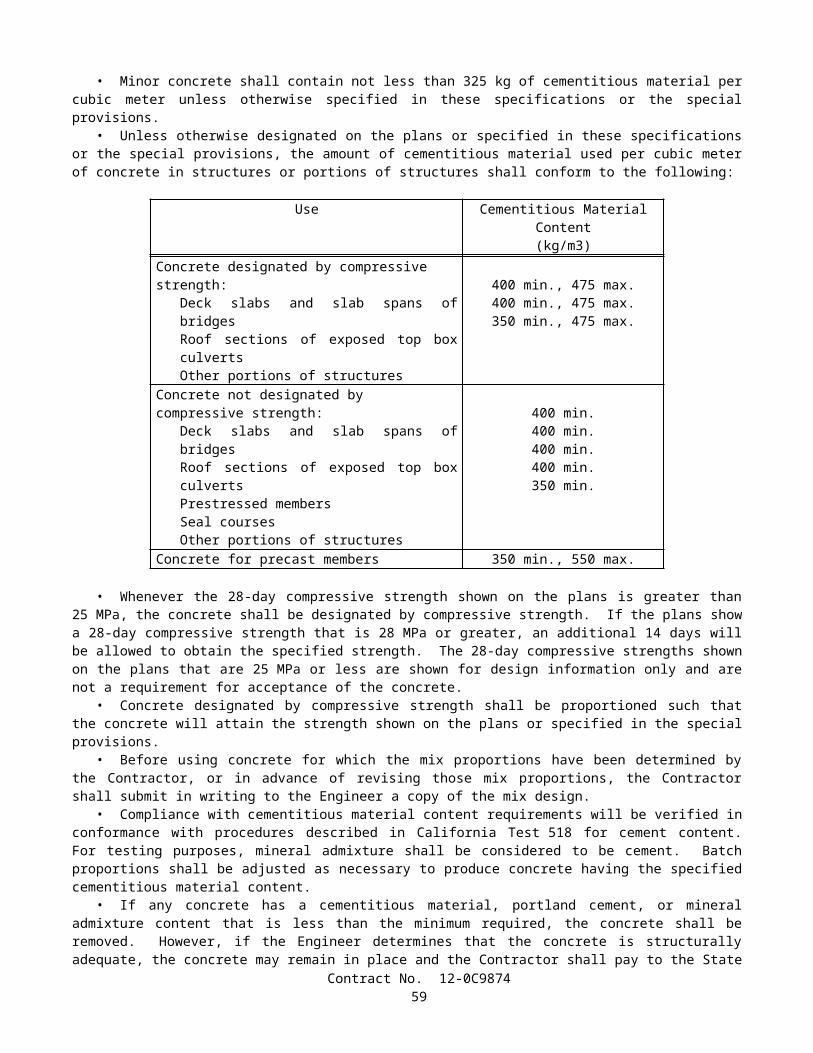
If any funds other than Federal funds have been paid for the same purposes in connection with this Federal-aid contract, the recipient shall submit an executed certification and, if required, submit a completed disclosure form as part of the bid documents.
A certification for Federal-aid contracts regarding payment of funds to lobby Congress or a Federal agency is included in the Proposal. Standard Form - LLL, "Disclosure of Lobbying Activities," with instructions for completion of the Standard Form is also included in the Proposal. Signing the Proposal shall constitute signature of the Certification.
The above-referenced certification and disclosure of lobbying activities shall be included in each subcontract and any lower-tier contracts exceeding $100,000. All disclosure forms, but not certifications, shall be forwarded from tier to tier until received by the Engineer.
The Contractor, subcontractors and any lower-tier contractors shall file a disclosure form at the end of each calendar quarter in which there occurs any event that requires disclosure or that materially affects the accuracy of the information contained in any disclosure form previously filed by the Contractor, subcontractors and any lower-tier contractors. An event that materially affects the accuracy of the information reported includes:
A. A cumulative increase of $25,000 or more in the amount paid or expected to be paid for influencing or attempting to influence a covered Federal action; or
B. A change in the person(s) or individual(s) influencing or attempting to influence a covered Federal action; or,C. A change in the officer(s), employee(s), or Member(s) contacted to influence or attempt to influence a covered
Federal action.
2-1.02 DISADVANTAGED BUSINESS ENTERPRISE (DBE)This project is subject to Part 26, Title 49, Code of Federal Regulations entitled "Participation by Disadvantaged
Business Enterprises in Department of Transportation Financial Assistance Programs." The Regulations in their entirety are incorporated herein by this reference.
Bidders shall be fully informed respecting the requirements of the Regulations and the Department's Disadvantaged Business Enterprise (DBE) program developed pursuant to the Regulations; particular attention is directed to the following matters:
A. A DBE must be a small business concern as defined pursuant to Section 3 of U.S. Small Business Act and relevant regulations promulgated pursuant thereto.
B. A DBE may participate as a prime contractor, subcontractor, joint venture partner with a prime or subcontractor, vendor of material or supplies, or as a trucking company.
C. A DBE bidder, not bidding as a joint venture with a non-DBE, will be required to document one or a combination of the following:
1. The bidder will meet the goal by performing work with its own forces.2. The bidder will meet the goal through work performed by DBE subcontractors, suppliers or trucking
companies.3. The bidder, prior to bidding, made adequate good faith efforts to meet the goal.
D. A DBE joint venture partner must be responsible for specific contract items of work, or portions thereof. Responsibility means actually performing, managing and supervising the work with its own forces. The DBE joint venture partner must share in the capital contribution, control, management, risks and profits of the joint venture. The DBE joint venturer must submit the joint venture agreement with the proposal or the DBE Information form required in the Section entitled "Submission of DBE Information" of these special provisions.
E. A DBE must perform a commercially useful function, i.e., must be responsible for the execution of a distinct element of the work and must carry out its responsibility by actually performing, managing and supervising the work.
F. DBEs must be certified by the California Unified Certification Program (CUCP). It is the contractor’s responsibility to confirm that the firm is DBE certified as of the date of bid opening. Listings of DBEs certified by the CUCP are available from the following sources:
1. The Department’s DBE Directory, which is published quarterly. This Directory may be obtained from the Department of Transportation, Materiel Operations Branch, Publication Distribution Unit, 1900 Royal Oaks Drive, Sacramento, California 95815, Telephone: (916) 445-3520.
2. The Department’s web site at http://www.dot.ca.gov/hq/bep.3. The organizations listed in the Section entitled "DBE Goal for this Project" of these special provisions.
Contract No. 12-0C987461
G. Credit for materials or supplies purchased from DBEs will be as follows:
1. If the materials or supplies are obtained from a DBE manufacturer, 100 percent of the cost of the materials or supplies will count toward the DBE goal. A DBE manufacturer is a firm that operates or maintains a factory or establishment that produces, on the premises, the materials, supplies, articles, or equipment required under the contract and of the general character described by the specifications.
2. If the materials or supplies are purchased from a DBE regular dealer, 60 percent of the cost of the materials or supplies will count toward the DBE goal. A DBE regular dealer is a firm that owns, operates, or maintains a store, warehouse, or other establishment in which the materials, supplies, articles or equipment of the general character described by the specifications and required under the contract are bought, kept in stock, and regularly sold or leased to the public in the usual course of business. To be a DBE regular dealer, the firm must be an established, regular business that engages, as its principal business and under its own name, in the purchase and sale or lease of the products in question. A person may be a DBE regular dealer in such bulk items as petroleum products, steel, cement, gravel, stone, or asphalt without owning, operating, or maintaining a place of business as provided in this paragraph G.2. if the person both owns and operates distribution equipment for the products. Any supplementing of regular dealers' own distribution equipment shall be by a long-term lease agreement and not on an ad hoc or contract-by-contract basis. Packagers, brokers, manufacturers' representatives, or other persons who arrange or expedite transactions are not DBE regular dealers within the meaning of this paragraph G.2.
3. Credit for materials or supplies purchased from a DBE which is neither a manufacturer nor a regular dealer will be limited to the entire amount of fees or commissions charged for assistance in the procurement of the materials and supplies, or fees or transportation charges for the delivery of materials or supplies required on a job site, provided the fees are reasonable and not excessive as compared with fees charged for similar services.
H. Credit for DBE trucking companies will be as follows:
1. The DBE must be responsible for the management and supervision of the entire trucking operation for which it is responsible on a particular contract, and there cannot be a contrived arrangement for the purpose of meeting the DBE goal.
2. The DBE must itself own and operate at least one fully licensed, insured, and operational truck used on the contract.
3. The DBE receives credit for the total value of the transportation services it provides on the contract using trucks its owns, insures, and operates using drivers it employs.
4. The DBE may lease trucks from another DBE firm, including an owner-operator who is certified as a DBE. The DBE who leases trucks from another DBE receives credit for the total value of the transportation services the lessee DBE provides on the contract.
5. The DBE may also lease trucks from a non-DBE firm, including an owner-operator. The DBE who leases trucks from a non-DBE is entitled to credit only for the fee or commission it receives as a result of the lease arrangement. The DBE does not receive credit for the total value of the transportation services provided by the lessee, since these services are not provided by a DBE.
6. For the purposes of this paragraph H, a lease must indicate that the DBE has exclusive use of and control over the truck. This does not preclude the leased truck from working for others during the term of the lease with the consent of the DBE, so long as the lease gives the DBE absolute priority for use of the leased truck. Leased trucks must display the name and identification number of the DBE.
I. Noncompliance by the Contractor with the requirements of the regulations constitutes a breach of this contract and may result in termination of the contract or other appropriate remedy for a breach of this contract.
J. Bidders are encouraged to use services offered by financial institutions owned and controlled by DBEs.
2-1.02A DBE GOAL FOR THIS PROJECTThe Department has established the following goal for Disadvantaged Business Enterprise (DBE) participation for this
project:
Disadvantaged Business Enterprise (DBE): 8 percent
Bidders may use the services of the following firms to contact interested DBEs. These firms are available to assist DBEs in preparing bids for subcontracting or supplying materials.
Contract No. 12-0C987462
The following firms may be contacted for projects in the following locations:
Districts 04, 05 (except San Luis Obispo and Santa Barbara Counties),06 (except Kern County) and 10: Districts 08 and 11:
See the Department's DBE database at: Padilla & Associateshttp://www.dot.ca.gov/hq/bep/ - San Diego
2725 Congress Street, Suite 1DSan Diego, CA 92110Telephone: (619) 725-0843FAX No.: (619) 725-0854
Districts 07, 08, and 12; in San Luis Obispo and Santa Barbara Countiesin District 05; and in Kern County in District 06: Districts 01, 02, 03 and 09:
Padilla & Associates See the Department's DBE database at: - Commerce http://www.dot.ca.gov/hq/bep/
5675 East Telegraph Rd., Suite A-260Commerce, CA 90040Telephone: (323) 728-8847FAX No.: (323) 728-8867
2-1.02B SUBMISSION OF DBE INFORMATIONAll bidders shall complete the "CALTRANS BIDDER - DBE INFORMATION" form included in the Proposal and
submit it WITH THE BID.Failure to submit the "CALTRANS BIDDER - DBE INFORMATION" form with the bid will be grounds for finding the
bid nonresponsive.The bidder shall submit written confirmation from each DBE that the DBE is participating in the contract, and include
the confirmation with the submittal of the bid or submit it by the time specified for submittal of the GOOD FAITH EFFORT (GFE) DOCUMENTATION form. A copy of a DBE's quote will serve as written confirmation that the DBE is participating in the contract.
Where the bidder has not met the designated DBE goal, it must submit good faith efforts (GFE) documentation to establish that, prior to the bid, it made adequate good faith efforts to meet the goal.
Bidders are cautioned that even though their "CALTRANS BIDDER - DBE INFORMATION" form indicates they will meet the stated DBE goal, they should also submit their GFE documentation within the time specified herein, to protect their eligibility for award of the contract in the event the Department, in its review, finds that the goal has not been met.
The apparent successful bidder (low bidder), the second low bidder and the third low bidder shall complete and submit the GOOD FAITH EFFORT (GFE) DOCUMENTATION form, if they have not met the goal, to the Department of Transportation, 1120 N Street, Room 0200, MS #26, Sacramento, California 95814 so the information is received by the Department no later than 4:00 p.m. ON THE FOURTH DAY, not including Saturdays, Sundays and legal holidays, following bid opening. GFE documentation sent by U.S. Postal Service certified mail with return receipt and certificate of mailing and mailed on or before the third day, not including Saturdays, Sundays and legal holidays, following bid opening will be accepted even if it is received after the fourth day following bid opening. Other bidders need not submit GFE documentation unless requested to do so by the Department. When a request is made by the Department, the GFE documentation of the other bidders shall be received by the Department within 4 days of the request, not including Saturdays, Sundays and legal holidays, unless a later time is authorized by the Department.
If it is determined that GFE documentation is needed to determine a bidder's eligibility for award, failure of the bidder to have submitted the GFE documentation by the time specified herein will be grounds for finding the bid or proposal nonresponsive.
It is the bidder's responsibility to make enough work available to DBEs and to select those portions of the work or material needs consistent with the available DBEs to meet the goal for DBE participation.
The bidder's "CALTRANS BIDDER - DBE INFORMATION" form shall include the names, addresses and phone numbers of DBE firms that will participate, with a complete description of work or supplies to be provided by each, and the
Contract No. 12-0C987463
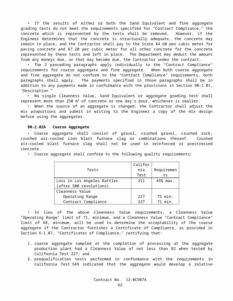
dollar value of each DBE transaction. When 100 percent of a contract item of work is not to be performed or furnished by a DBE, a description of the exact portion of that work to be performed or furnished by that DBE shall be included in the DBE information, including the planned location of that work. The work that a DBE prime contractor has committed to performing with its own forces as well as the work that it has committed to be performed by DBE subcontractors, suppliers and trucking companies will count toward the goal.
The bidder's good faith effort (GFE) documentation shall establish that good faith efforts to meet the DBE goal have been made.
In order to establish the bidder's good faith efforts to meet the DBE goal, the bidder should include the following information and supporting documents, as necessary:
A. Items of work the bidder has made available to DBE firms. Identify those items of work the bidder might otherwise perform with its own forces and those items that have been broken down into economically feasible units to facilitate DBE participation. For each item listed, show the dollar value and percentage of the total contract. It is the bidder's responsibility to demonstrate that sufficient work to meet the goal was made available to DBE firms.
B. The names of certified DBEs and the dates on which they were solicited to bid on the project. Include the items of work offered. Describe the methods used for following up initial solicitations to determine with certainty if the DBEs were interested, and the dates of the follow-up. Attach supporting documents such as copies of letters, memos, facsimiles sent, telephone logs, telephone billing statements, and other evidence of solicitation. Bidders are reminded to solicit certified DBEs through all reasonable and available means and provide sufficient time to allow DBEs to respond.
C. For each item of work made available, the DBEs that provided quotes, the selected firm and its status as a DBE, the price quote for each firm, and the name, address and telephone number for each firm. If the firm selected for the item is not a DBE, provide the reasons for the selection.
D. The names and dates of each publication in which a request for DBE participation for the project was placed by the bidder. Attach copies of the published advertisements.
E. The names of agencies, including the firms listed in Section 2-1.02A, "DBE Goal for this Project," and the dates on which they were contacted to provide assistance in contacting, recruiting and using DBE firms. If the agencies were contacted in writing, provide copies of supporting documents.
F. Descriptions of the efforts made to provide interested DBEs with adequate information about the plans, specifications and requirements of the contract to assist them in responding to a solicitation. Where the bidder has provided information, identify the name of the DBE assisted, the nature of the information provided, and date of contact. Provide copies of supporting documents, as appropriate.
G. Descriptions of any and all efforts made to assist interested DBEs in obtaining bonding, lines of credit, insurance, necessary equipment, supplies, and materials (excluding supplies and equipment which the DBE subcontractor purchases or leases from the prime contractor or its affiliate). Where such assistance was provided by the bidder, identify the name of the DBE assisted, nature of the assistance offered, and date. Provide copies of supporting documents, as appropriate.
H. Any additional data to support a demonstration of good faith efforts.
SECTION 3. AWARD AND EXECUTION OF CONTRACTThe bidder's attention is directed to the provisions in Section 3, "Award and Execution of Contract," of the Standard
Specifications and these special provisions for the requirements and conditions concerning award and execution of contract.Bid protests are to be delivered to the following address: Department of Transportation, MS 43, Attn: Office Engineer,
1727 30th Street, Sacramento, CA 95816 or by facsimile to the Office Engineer at (916) 227-6282.The award of the contract, if it be awarded, will be made within 30 days after the opening of the proposals if the apparent
lowest bidder has met the goal for DBE participation. The award of the contract, if it be awarded, will be made within 60 days after the opening of the proposals if the apparent lowest bidder has not met the goal for DBE participation but has claimed good faith efforts to do so. These periods will be subject to extension for such further periods as may be agreed upon in writing between the Department and the bidders concerned. The award, if made, will be to the lowest responsible bidder whose proposal complies with all the requirements prescribed and who has met the goal for DBE participation or has demonstrated, to the satisfaction of the Department, adequate good faith efforts to do so. Meeting the goal for DBE participation or demonstrating, to the satisfaction of the Department, adequate good faith efforts to do so is a condition for being eligible for award of contract.
The contract shall be executed by the successful bidder and shall be returned, together with the contract bonds, to the Department so that it is received within 10 days, not including Saturdays, Sundays and legal holidays, after the bidder has received the contract for execution. Failure to do so shall be just cause for forfeiture of the proposal guaranty. The executed contract documents shall be delivered to the following address: Department of Transportation MS 43, Attn: Office Engineer, 1727 30th Street, Sacramento, CA 95816.
Contract No. 12-0C987464
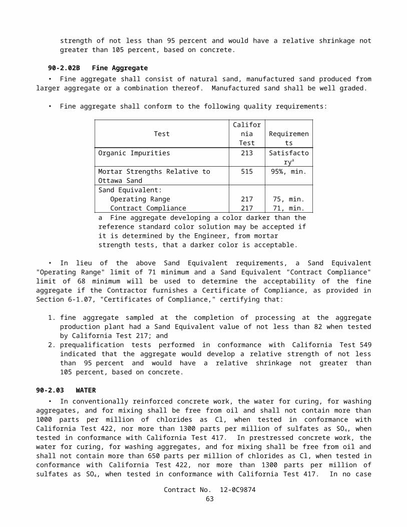
A "Payee Data Record" form will be included in the contract documents to be executed by the successful bidder. The purpose of the form is to facilitate the collection of taxpayer identification data. The form shall be completed and returned to the Department by the successful bidder with the executed contract and contract bonds. For the purposes of the form, payee shall be deemed to mean the successful bidder. The form is not to be completed for subcontractors or suppliers. Failure to complete and return the "Payee Data Record" form to the Department as provided herein will result in the retention of 31 percent of payments due the contractor and penalties of up to $20,000. This retention of payments for failure to complete the "Payee Data Record" form is in addition to any other retention of payments due the Contractor.
SECTION 4. BEGINNING OF WORK, TIME OF COMPLETION AND LIQUIDATED DAMAGESAttention is directed to the provisions in Section 8-1.03, "Beginning of Work," Section 8-1.06, "Time of Completion,"
and Section 8-1.07, "Liquidated Damages," of the Standard Specifications and these special provisions.The Contractor shall begin work within 15 calendar days after the contract has been approved by the Attorney General or
the attorney appointed and authorized to represent the Department of Transportation.This work shall be diligently prosecuted to completion before the expiration of 180 WORKING DAYS beginning on
the fifteenth calendar day after approval of the contract.The Contractor shall pay to the State of California the sum of $700 per day, for each and every calendar day's delay in
finishing the work in excess of 180 WORKING DAYS.
SECTION 5. GENERAL
SECTION 5-1. MISCELLANEOUS
5-1.01 PLANS AND WORKING DRAWINGSWhen the specifications require working drawings to be submitted to the Division of Structure Design, the drawings
shall be submitted to: Division of Structure Design, Documents Unit, Mail Station 9, 1801 30th Street, Sacramento, CA 95816, Telephone 916 227-8252.
5-1.011 EXAMINATION OF PLANS, SPECIFICATIONS, CONTRACT, AND SITE OF WORKAttention is directed to "Differing Site Conditions" of these special provisions regarding physical conditions at the site
which may differ from those indicated in "Materials Information," log of test borings or other geotechnical information obtained by the Department's investigation of site conditions.
5-1.012 DIFFERING SITE CONDITIONSAttention is directed to Section 5-1.116, "Differing Site Conditions," of the Standard Specifications.During the progress of the work, if subsurface or latent conditions are encountered at the site differing materially from
those indicated in the "Materials Information," log of test borings, other geotechnical data obtained by the Department's investigation of subsurface conditions, or an examination of the conditions above ground at the site, the party discovering those conditions shall promptly notify the other party in writing of the specific differing conditions before they are disturbed and before the affected work is performed.
The Contractor will be allowed 15 days from the notification of the Engineer's determination of whether or not an adjustment of the contract is warranted, in which to file a notice of potential claim in conformance with the provisions of Section 9-1.04, "Notice of Potential Claim," of the Standard Specifications and as specified herein; otherwise the decision of the Engineer shall be deemed to have been accepted by the Contractor as correct. The notice of potential claim shall set forth in what respects the Contractor's position differs from the Engineer's determination and provide any additional information obtained by the Contractor, including but not limited to additional geotechnical data. The notice of potential claim shall be accompanied by the Contractor's certification that the following were made in preparation of the bid: a review of the contract, a review of the "Materials Information," a review of the log of test borings and other records of geotechnical data to the extent they were made available to bidders prior to the opening of bids, and an examination of the conditions above ground at the site. Supplementary information, obtained by the Contractor subsequent to the filing of the notice of potential claim, shall be submitted to the Engineer in an expeditious manner.
5-1.013 LINES AND GRADESAttention is directed to Section 5-1.07, "Lines and Grades," of the Standard Specifications.Stakes or marks will be set by the Engineer in conformance with the requirements in Chapter 12, "Construction
Surveys," of the Department's Surveys Manual.
Contract No. 12-0C987465
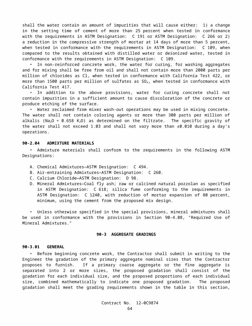
5-1.015 LABORATORYWhen a reference is made in the specifications to the "Laboratory," the reference shall mean Division of Engineering
Services - Materials Engineering and Testing Services and Division of Engineering Services - Geotechnical Services of the Department of Transportation, or established laboratories of the various Districts of the Department, or other laboratories authorized by the Department to test materials and work involved in the contract. When a reference is made in the specifications to the "Transportation Laboratory," the reference shall mean Division of Engineering Services - Materials Engineering and Testing Services and Division of Engineering Services - Geotechnical Services, located at 5900 Folsom Boulevard, Sacramento, CA 95819, Telephone (916) 227-7000.
5-1.017 CONTRACT BONDSAttention is directed to Section 3-1.02, "Contract Bonds," of the Standard Specifications and these special provisions.The payment bond shall be in a sum not less than one hundred percent of the total amount payable by the terms of the
contract.
5-1.019 COST REDUCTION INCENTIVEAttention is directed to Section 5-1.14, "Cost Reduction Incentive," of the Standard Specifications.Prior to preparing a written cost reduction proposal, the Contractor shall request a meeting with the Engineer to discuss
the proposal in concept. Items of discussion will also include permit issues, impact on other projects, impact on the project schedule, peer reviews, overall merit of the proposal, and review times required by the Department and other agencies.
If a cost reduction proposal submitted by the Contractor, and subsequently approved by the Engineer, provides for a reduction in contract time, 50 percent of that contract time reduction shall be credited to the State by reducing the contract working days, not including plant establishment. Attention is directed to "Beginning of Work, Time of Completion and Liquidated Damages" of these special provisions regarding the working days.
If a cost reduction proposal submitted by the Contractor, and subsequently approved by the Engineer, provides for a reduction in traffic congestion or avoids traffic congestion during construction, 60 percent of the estimated net savings in construction costs attributable to the cost reduction proposal will be paid to the Contractor. In addition to the requirements in Section 5-1.14, "Cost Reduction Incentive," of the Standard Specifications, the Contractor shall provide detailed comparisons of the traffic handling between the existing contract and the proposed change, and estimates of the traffic volumes and congestion.
5-1.02 LABOR NONDISCRIMINATIONAttention is directed to the following Notice that is required by Chapter 5 of Division 4 of Title 2, California Code of
Regulations.
NOTICE OF REQUIREMENT FOR NONDISCRIMINATION PROGRAM
(GOV. CODE, SECTION 12990)Your attention is called to the "Nondiscrimination Clause", set forth in Section 7-1.01A(4), "Labor Nondiscrimination," of the Standard Specifications, which is applicable to all nonexempt State contracts and subcontracts, and to the "Standard California Nondiscrimination Construction Contract Specifications" set forth therein. The specifications are applicable to all nonexempt State construction contracts and subcontracts of $5000 or more.
5-1.022 EXCLUSION OF RETENTIONIn conformance with 49 CFR, Part 26, Subpart B, Section 26.29 (b)(1), the retention of proceeds required by Public
Contract Code Section 10261 shall not apply. In conformance with Public Contract Code 7200 (b), in subcontracts between the Contractor and a subcontractor and in subcontracts between a subcontractor and any subcontractor thereunder, retention proceeds shall not be withheld, and the exceptions provided in Public Contract Code 7200 (c) shall not apply. At the option of the Contractor, subcontractors may be required to furnish payment and performance bonds issued by an admitted surety insurer.
The third paragraph of Section 9-1.06, "Partial Payments," of the Standard Specifications, and Section 9-1.065, "Payment of Withheld Funds," of the Standard Specifications shall not apply.
5-1.023 UNSATISFACTORY PROGRESSIf the number of working days charged to the contract exceeds 75 percent of the working days in the current time of
completion and the percent working days elapsed exceeds the percent work completed by more than 15 percentage points, the Department will withhold 10 percent of the amount due on the current monthly estimate.
Contract No. 12-0C987466
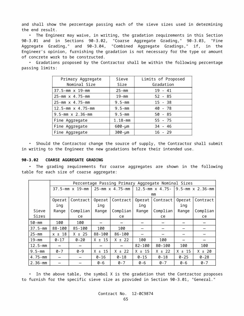
The percent working days elapsed will be determined from the number of working days charged to the contract divided by the number of contract working days in the current time of completion, expressed as a percentage. The number of contract working days in the current time of completion shall consist of the original contract working days increased or decreased by time adjustment s approved by the Engineer.
The percent work completed will be determined by the Engineer from the sum of payments made to date plus the amount due on the current monthly estimate, divided by the current total estimated value of the work, expressed as a percentage.
When the percent of working days elapsed minus the percent of work completed is less than or equal to 15 percentage points, the funds withheld shall be returned to the Contractor with the next monthly progress payment.
Funds kept or withheld from payment, due to the failure of the Contractor to comply with the provisions of the contract, will not be subject to the requirements of Public Contract Code 7107 or to the payment of interest pursuant to Public Contract Code Section 10261.5.
5-1.03 INTEREST ON PAYMENTSInterest shall be payable on progress payments, payments after acceptance, final payments, extra work payments, and
claim payments as follows:
A. Unpaid progress payments, payment after acceptance, and final payments shall begin to accrue interest 30 days after the Engineer prepares the payment estimate.
B. Unpaid extra work bills shall begin to accrue interest 30 days after preparation of the first pay estimate following receipt of a properly submitted and undisputed extra work bill. To be properly submitted, the bill must be submitted within 7 days of the performance of the extra work and in conformance with the provisions in Section 9 -1.03C, "Records," and Section 9-1.06, "Partial Payments," of the Standard Specifications. An undisputed extra work bill not submitted within 7 days of performance of the extra work will begin to accrue interest 30 days after the preparation of the second pay estimate following submittal of the bill.
C. The rate of interest payable for unpaid progress payments, payments after acceptance, final payments, and extra work payments shall be 10 percent per annum.
D. The rate of interest payable on a claim, protest or dispute ultimately allowed under this contract shall be 6 percent per annum. Interest shall begin to accrue 61 days after the Contractor submits to the Engineer information in sufficient detail to enable the Engineer to ascertain the basis and amount of said claim, protest or dispute.
The rate of interest payable on any award in arbitration shall be 6 percent per annum if allowed under the provisions of Civil Code Section 3289.
5-1.04 PUBLIC SAFETYThe Contractor shall provide for the safety of traffic and the public in conformance with the provisions in Section 7 -1.09,
"Public Safety," of the Standard Specifications and these special provisions.The Contractor shall install temporary railing (Type K) between a lane open to public traffic and an excavation, obstacle
or storage area when the following conditions exist:
A. Excavations.—The near edge of the excavation is 3.6 m or less from the edge of the lane, except:
1. Excavations covered with sheet steel or concrete covers of adequate thickness to prevent accidental entry by traffic or the public.
2. Excavations less than 0.3-m deep.3. Trenches less than 0.3-m wide for irrigation pipe or electrical conduit, or excavations less than 0.3-m in
diameter.4. Excavations parallel to the lane for the purpose of pavement widening or reconstruction.5. Excavations in side slopes, where the slope is steeper than 1:4 (vertical:horizontal).6. Excavations protected by existing barrier or railing.
B. Temporarily Unprotected Permanent Obstacles.—The work includes the installation of a fixed obstacle together with a protective system, such as a sign structure together with protective railing, and the Contractor elects to install the obstacle prior to installing the protective system; or the Contractor, for the Contractor's convenience and with permission of the Engineer, removes a portion of an existing protective railing at an obstacle and does not replace such railing complete in place during the same day.
C. Storage Areas.—Material or equipment is stored within 3.6 m of the lane and the storage is not otherwise prohibited by the provisions of the Standard Specifications and these special provisions.
Contract No. 12-0C987467
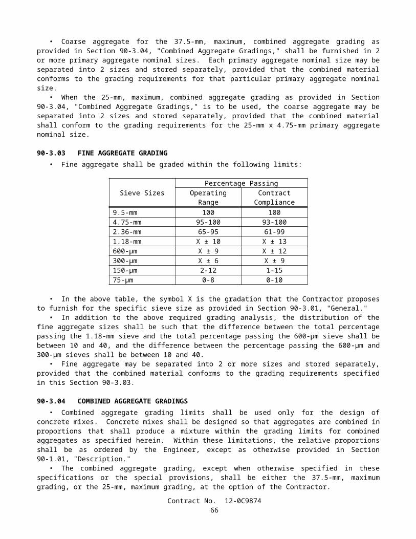
The approach end of temporary railing (Type K), installed in conformance with the provisions in this section "Public Safety" and in Section 7-1.09, "Public Safety," of the Standard Specifications, shall be offset a minimum of 4.6 m from the edge of the traffic lane open to public traffic. The temporary railing shall be installed on a skew toward the edge of the traffic lane of not more than 0.3-m transversely to 3 m longitudinally with respect to the edge of the traffic lane. If the 4.6 -m minimum offset cannot be achieved, the temporary railing shall be installed on the 10 to 1 skew to obtain the maximum available offset between the approach end of the railing and the edge of the traffic lane, and an array of temporary crash cushion modules shall be installed at the approach end of the temporary railing.
Temporary railing (Type K) shall conform to the provisions in Section 12-3.08, "Temporary Railing (Type K)," of the Standard Specifications. Temporary railing (Type K), conforming to the details shown on 1999 Standard Plan T3, may be used. Temporary railing (Type K) fabricated prior to January 1, 1993, and conforming to 1988 Standard Plan B11-30 may be used, provided the fabrication date is printed on the required Certificate of Compliance.
Temporary crash cushion modules shall conform to the provisions in "Temporary Crash Cushion Module" of these special provisions.
Except for installing, maintaining and removing traffic control devices, whenever work is performed or equipment is operated in the following work areas, the Contractor shall close the adjacent traffic lane unless otherwise provided in the Standard Specifications and these special provisions:
Approach Speed of Public Traffic (Posted Limit) (Kilometers Per Hour)
Work Areas
Over 72 (45 Miles Per Hour) Within 1.8 m of a traffic lane but not on a traffic lane56 to 72 (35 to 45 Miles Per Hour) Within 0.9-m of a traffic lane but not on a traffic lane
The lane closure provisions of this section shall not apply if the work area is protected by permanent or temporary railing or barrier.
When traffic cones or delineators are used to delineate a temporary edge of a traffic lane, the line of cones or delineators shall be considered to be the edge of the traffic lane, however, the Contractor shall not reduce the width of an existing lane to less than 3 m without written approval from the Engineer.
When work is not in progress on a trench or other excavation that required closure of an adjacent lane, the traffic cones or portable delineators used for the lane closure shall be placed off of and adjacent to the edge of the traveled way. The spacing of the cones or delineators shall be not more than the spacing used for the lane closure.
Suspended loads or equipment shall not be moved nor positioned over public traffic or pedestrians.Full compensation for conforming to the provisions in this section "Public Safety," including furnishing and installing
temporary railing (Type K) and temporary crash cushion modules, shall be considered as included in the contract prices paid for the various items of work involved and no additional compensation will be allowed therefor.
5-1.05 TESTINGTesting of materials and work shall conform to the provisions in Section 6-3, "Testing," of the Standard Specifications
and these special provisions.Whenever the provisions of Section 6-3.01, "General," of the Standard Specifications refer to tests or testing, it shall
mean tests to assure the quality and to determine the acceptability of the materials and work.The Engineer will deduct the costs for testing of materials and work found to be unacceptable, as determined by the tests
performed by the Department, and the costs for testing of material sources identified by the Contractor which are not used for the work, from moneys due or to become due to the Contractor. The amount deducted will be determined by the Engineer.
5-1.06 REMOVAL OF ASBESTOS AND HAZARDOUS SUBSTANCESWhen the presence of asbestos or hazardous substances are not shown on the plans or indicated in the specifications and
the Contractor encounters materials which the Contractor reasonably believes to be asbestos or a hazardous substance as defined in Section 25914.1 of the Health and Safety Code, and the asbestos or hazardous substance has not been rendered harmless, the Contractor may continue work in unaffected areas reasonably believed to be safe. The Contractor shall immediately cease work in the affected area and report the condition to the Engineer in writing.
In conformance with Section 25914.1 of the Health and Safety Code, removal of asbestos or hazardous substances including exploratory work to identify and determine the extent of the asbestos or hazardous substance will be performed by separate contract.
If delay of work in the area delays the current controlling operation, the delay will be considered a right of way delay and the Contractor will be compensated for the delay in conformance with the provisions in Section 8-1.09, "Right of Way Delays," of the Standard Specifications.
Contract No. 12-0C987468
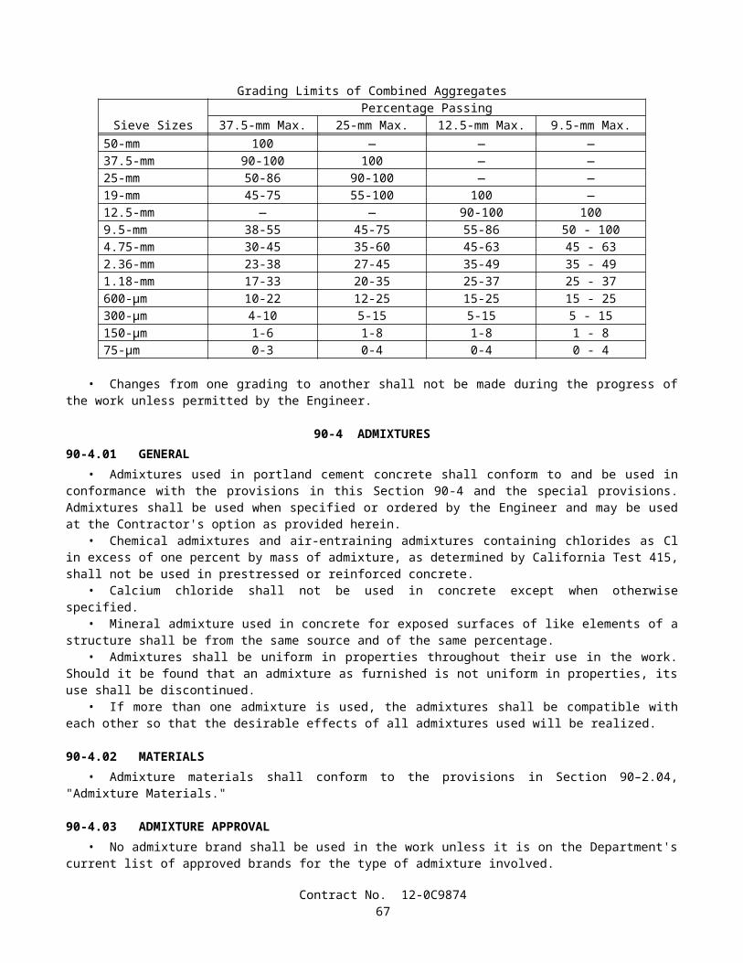
5-1.07 YEAR 2000 COMPLIANCEThis contract is subject to Year 2000 Compliance for automated devices in the State of California.Year 2000 compliance for automated devices in the State of California is achieved when embedded functions have or
create no logical or mathematical inconsistencies when dealing with dates prior to and beyond 1999. The year 2000 is recognized and processed as a leap year. The product shall operate accurately in the manner in which the product was intended for date operation without requiring manual intervention.
The Contractor shall provide the Engineer a Certificate of Compliance from the manufacturer in conformance with the provisions in Section 6-1.07, "Certificates of Compliance," of the Standard Specifications for all automated devices furnished for the project.
5-1.075 BUY AMERICA REQUIREMENTSAttention is directed to the "Buy America" requirements of the Surface Transportation Assistance Act of 1982 (Section
165) and the Intermodal Surface Transportation Efficiency Act of 1991 (ISTEA) Sections 1041(a) and 1048(a), and the regulations adopted pursuant thereto. In conformance with the law and regulations, all manufacturing processes for steel and iron materials furnished for incorporation into the work on this project shall occur in the United States; with the exception that pig iron and processed, pelletized and reduced iron ore manufactured outside of the United States may be used in the domestic manufacturing process for such steel and iron materials. The application of coatings, such as epoxy coating, galvanizing, painting, and other coatings that protect or enhance the value of steel or iron materials shall be considered a manufacturing process subject to the "Buy America" requirements.
A Certificate of Compliance conforming to the provisions in Section 6-1.07, "Certificates of Compliance," of the Standard Specifications shall be furnished for steel and iron materials. The certificates, in addition to certifying that the materials comply with the specifications, shall specifically certify that all manufacturing processes for the materials occurred in the United States, except for the above exceptions.
The requirements imposed by the law and regulations do not prevent a minimal use of foreign steel and iron materials if the total combined cost of the materials used does not exceed one-tenth of one percent (0.1 percent) of the total contract cost or $2500, whichever is greater. The Contractor shall furnish the Engineer acceptable documentation of the quantity and value of the foreign steel and iron prior to incorporating the materials into the work.
5-1.08 SUBCONTRACTOR AND DBE RECORDSThe Contractor shall maintain records showing the name and business address of each first-tier subcontractor. The
records shall also show the name and business address of every DBE subcontractor, DBE vendor of materials and DBE trucking company, regardless of tier. The records shall show the date of payment and the total dollar figure paid to all of these firms. DBE prime contractors shall also show the date of work performed by their own forces along with the corresponding dollar value of the work.
Upon completion of the contract, a summary of these records shall be prepared on Form CEM-2402 (F) and certified correct by the Contractor or the Contractor's authorized representative, and shall be furnished to the Engineer. The form shall be furnished to the Engineer within 90 days from the date of contract acceptance. $10,000 will be withheld from payment until the Form CEM-2402 (F) is submitted. The amount will be returned to the Contractor when a satisfactory Form CEM-2402 (F) is submitted.
Prior to the fifteenth of each month, the Contractor shall submit documentation to the Engineer showing the amount paid to DBE trucking companies listed in the Contractor's DBE information. This monthly documentation shall indicate the portion of the revenue paid to DBE trucking companies which is claimed toward DBE participation. The Contractor shall also obtain and submit documentation to the Engineer showing the amount paid by DBE trucking companies to all firms, including owner-operators, for the leasing of trucks. The DBE who leases trucks from a non-DBE is entitled to credit only for the fee or commission it receives as a result of the lease arrangement. The records must confirm that the amount of credit claimed toward DBE participation conforms with Section 2-1.02, "Disadvantaged Business Enterprise," of these special provisions.
The Contractor shall also obtain and submit documentation to the Engineer showing the truck number, owner's name, California Highway Patrol CA number, and if applicable, the DBE certification number of the owner of the truck for all trucks used during that month for which DBE participation will be claimed. This documentation shall be submitted on Form CEM-2404 (F).
5-1.083 DBE CERTIFICATION STATUSIf a DBE subcontractor is decertified during the life of the project, the decertified subcontractor shall notify the
Contractor in writing with the date of decertification. If a subcontractor becomes a certified DBE during the life of the project, the subcontractor shall notify the Contractor in writing with the date of certification. The Contractor shall furnish the written documentation to the Engineer.
Contract No. 12-0C987469
Upon completion of the contract, Form CEM-2403 (F) indicating the DBE's existing certification status shall be signed and certified correct by the Contractor. The certified form shall be furnished to the Engineer within 90 days from the date of contract acceptance.
5-1.086 PERFORMANCE OF DBE SUBCONTRACTORS AND SUPPLIERSThe DBEs listed by the Contractor in response to the provisions in Section 2-1.02B, "Submission of DBE Information,"
and Section 3, "Award and Execution of Contract," of these special provisions, which are determined by the Department to be certified DBEs, shall perform the work and supply the materials for which they are listed, unless the Contractor has received prior written authorization to perform the work with other forces or to obtain the materials from other sources.
Authorization to use other forces or sources of materials may be requested for the following reasons:
A. The listed DBE, after having had a reasonable opportunity to do so, fails or refuses to execute a written contract, when such written contract, based upon the general terms, conditions, plans and specifications for the project, or on the terms of such subcontractor's or supplier's written bid, is presented by the Contractor.
B. The listed DBE becomes bankrupt or insolvent.C. The listed DBE fails or refuses to perform the subcontract or furnish the listed materials.D. The Contractor stipulated that a bond was a condition of executing a subcontract and the listed DBE subcontractor
fails or refuses to meet the bond requirements of the Contractor.E. The work performed by the listed subcontractor is substantially unsatisfactory and is not in substantial conformance
with the plans and specifications, or the subcontractor is substantially delaying or disrupting the progress of the work.
F. It would be in the best interest of the State.
The Contractor shall not be entitled to any payment for such work or material unless it is performed or supplied by the listed DBE or by other forces (including those of the Contractor) pursuant to prior written authorization of the Engineer.
5-1.09 SUBCONTRACTINGAttention is directed to the provisions in Section 8-1.01, "Subcontracting," of the Standard Specifications, and Section 2,
"Proposal Requirements and Conditions," and Section 3, "Award and Execution of Contract," of these special provisions.Pursuant to the provisions of Section 1777.1 of the Labor Code, the Labor Commissioner publishes and distributes a list
of contractors ineligible to perform work as a subcontractor on a public works project. This list of debarred contractors is available from the Department of Industrial Relations web site at:
http://www.dir.ca.gov/DLSE/Debar.html.
The provisions in the third paragraph of Section 8-1.01, "Subcontracting," of the Standard Specifications, that the Contractor shall perform with the Contractor's own organization contract work amounting to not less than 50 percent of the original contract price, is not changed by the Federal Aid requirement specified under "Required Contract Provisions Federal-Aid Construction Contracts" in Section 14 of these special provisions that the Contractor perform not less than 30 percent of the original contract work with the Contractor's own organization.
Each subcontract and any lower tier subcontract that may in turn be made shall include the "Required Contract Provisions Federal-Aid Construction Contracts" in Section 14 of these special provisions. This requirement shall be enforced as follows:
A. Noncompliance shall be corrected. Payment for subcontracted work involved will be withheld from progress payments due, or to become due, until correction is made. Failure to comply may result in termination of the contract.
In conformance with the Federal DBE regulations Sections 26.53(f)(1) and 26.53(f)(2) Part 26, Title 49 CFR:
A. The Contractor shall not terminate for convenience a DBE subcontractor listed in response to Section 2-1.02B, "Submission of DBE Information," and then perform that work with its own forces, or those of an affiliate without the written consent of the Department, and
B. If a DBE subcontractor is terminated or fails to complete its work for any reason, the Contractor will be required to make good faith efforts to substitute another DBE subcontractor for the original DBE subcontractor, to the extent needed to meet the contract goal.
Contract No. 12-0C987470
The requirement in Section 2-1.02, "Disadvantaged Business Enterprise (DBE)," of these special provisions that DBEs must be certified on the date bids are opened does not apply to DBE substitutions after award of the contract.
5-1.10 PROMPT PROGRESS PAYMENT TO SUBCONTRACTORSAttention is directed to the provisions in Sections 10262 and 10262.5 of the Public Contract Code concerning prompt
payment to subcontractors.
5-1.103 RECORDSThe Contractor shall maintain cost accounting records for the contract pertaining to, and in such a manner as to provide a
clear distinction between, the following six categories of costs of work during the life of the contract:
A. Direct costs of contract item work.B. Direct costs of changes in character in conformance with Section 4-1.03C, "Changes in Character of Work," of the
Standard Specifications.C. Direct costs of extra work in conformance with Section 4-1.03D, "Extra Work," of the Standard Specifications.D. Direct costs of work not required by the contract and performed for others.E. Direct costs of work performed under a notice of potential claim in conformance with the provisions in Section
9-1.04, "Notice of Potential Claim," of the Standard Specifications.F. Indirect costs of overhead.
Cost accounting records shall include the information specified for daily extra work reports in Section 9-1.03C, "Records," of the Standard Specifications. The requirements for furnishing the Engineer completed daily extra work reports shall only apply to work paid for on a force account basis.
The cost accounting records for the contract shall be maintained separately from other contracts, during the life of the contract, and for a period of not less than 3 years after the date of acceptance of the contract. If the Contractor intends to file claims against the Department, the Contractor shall keep the cost accounting records specified above until complete resolution of all claims has been reached.
5-1.11 AREAS FOR CONTRACTOR'S USEAttention is directed to the provisions in Section 7-1.19, "Rights in Land and Improvements," of the Standard
Specifications and these special provisions.The highway right of way shall be used only for purposes that are necessary to perform the required work. The
Contractor shall not occupy the right of way, or allow others to occupy the right of way, for purposes which are not necessary to perform the required work.
No State-owned parcels adjacent to the right of way are available for the exclusive use of the Contractor within the contract limits. The Contractor shall secure, at the Contractor's own expense, areas required for plant sites, storage of equipment or materials, or for other purposes.
No area is available within the contract limits for the exclusive use of the Contractor. However, temporary storage of equipment and materials on State property may be arranged with the Engineer, subject to the prior demands of State maintenance forces and to other contract requirements. Use of the Contractor's work areas and other State-owned property shall be at the Contractor's own risk, and the State shall not be held liable for damage to or loss of materials or equipment located within such areas.
The Contractor shall remove equipment, materials, and rubbish from the work areas and other State-owned property which the Contractor occupies. The Contractor shall leave the areas in a presentable condition in conformance with the provisions in Section 4-1.02, "Final Cleaning Up," of the Standard Specifications.
5-1.12 PAYMENTSAttention is directed to Sections 9-1.06, "Partial Payments," and 9-1.07, "Payment After Acceptance," of the Standard
Specifications and these special provisions.For the purpose of making partial payments pursuant to Section 9-1.06, "Partial Payments," of the Standard
Specifications, the amount set forth for the contract items of work hereinafter listed shall be deemed to be the maximum value of the contract item of work which will be recognized for progress payment purposes:
A. Clearing and Grubbing $ 25,000 B. Prepare Storm Water
Pollution Prevention Plan $ 7,500
Contract No. 12-0C987471
After acceptance of the contract pursuant to the provisions in Section 7-1.17, "Acceptance of Contract," of the Standard Specifications, the amount, if any, payable for a contract item of work in excess of the maximum value for progress payment purposes hereinabove listed for the item, will be included for payment in the first estimate made after acceptance of the contract.
In determining the partial payments to be made to the Contractor, only the following listed materials will be considered for inclusion in the payment as materials furnished but not incorporated in the work:
A. Alternative Pipe Culvert and Appurtenances B. Corrugated Steel Pipe Riser and AppurtenancesC. Precast Concrete Pipe ManholeD. Miscellaneous Iron and Steel
5-1.13 SOUND CONTROL REQUIREMENTSSound control shall conform to the provisions in Section 7-1.01I, "Sound Control Requirements," of the Standard
Specifications and these special provisions.The noise level from the Contractor's operations, between the hours of 9:00 p.m. and 6:00 a.m., shall not exceed 86 dBa
at a distance of 15 m. This requirement shall not relieve the Contractor from responsibility for complying with local ordinances regulating noise level.
The noise level requirement shall apply to the equipment on the job or related to the job, including but not limited to trucks, transit mixers or transient equipment that may or may not be owned by the Contractor. The use of loud sound signals shall be avoided in favor of light warnings except those required by safety laws for the protection of personnel.
Full compensation for conforming to the requirements of this section shall be considered as included in the prices paid for the various contract items of work involved and no additional compensation will be allowed therefor.
5-1.14 RELATIONS WITH CALIFORNIA DEPARTMENT OF FISH AND GAMEA portion of this project is located within the jurisdiction of the California Department of Fish and Game. An agreement
regarding a stream or lake has been entered into by the Department of Transportation and the Department of Fish and Game. The Contractor shall be fully informed of the requirements of this agreement as well as rules, regulations, and conditions that may govern the Contractor's operations in these areas and shall conduct the work accordingly.
Copies of the agreement are available for inspection at the office of the District Director of Transportation at District 12, 3347 Michelson Drive, Suite 100, Irvine CA 92612 Telephone (949)724-2128.
It is unlawful for any person to divert, obstruct or change the natural flow of the bed, channel or bank of a stream, river or lake without first notifying the Department of Fish and Game, unless the project or activity is noticed and constructed in conformance with conditions imposed under Fish and Game Code Section 1601.
Attention is directed to Sections 7-1.01, "Laws to be Observed," 7-1.01G, "Water Pollution," and 7-1.12, "Indemnification and Insurance," of the Standard Specifications.
Modifications to the agreement between the Department of Transportation and the Department of Fish and Game which are proposed by the Contractor shall be submitted in writing to the Engineer for transmittal to the Department of Fish and Game for their consideration.
When the Contractor is notified by the Engineer that a modification to the agreement is under consideration, no work shall be performed which is inconsistent with the original agreement or proposed modification until the Departments take action on the proposed modifications. Compensation for delay will be determined in conformance with the provisions in Section 8-1.09, "Right of Way Delays," of the Standard Specifications.
The provisions of this section shall be made a part of every subcontract executed pursuant to this contract.Modifications to any agreement between the Department of Transportation and the Department of Fish and Game will be
fully binding on the Contractor. The provisions of this section shall be made a part of every subcontract executed pursuant to this contract.
5-1.15 RELATIONS WITH CALIFORNIA REGIONAL WATER QUALITY CONTROL BOARDThe location of basin 1032L is within an area controlled by the Santa Ana Regional Water Quality Control Board
(SARWQCB). Regional Water Quality Control Board Order No. 2003-0061, NPDES Permit No. CAG998001 (DeMinimus/Dewatering Discharges) has been issued covering work to be performed under this contract. The Contractor shall be fully informed of rules, regulations, and conditions that may govern the Contractor's operations in the areas and shall conduct the work accordingly.
The location of basins 583L, 659L, and 696R are within an area controlled by the San Diego Regional Water Quality Control Board (SDRWQCB). Regional Water Quality Control Board Order No. 2001-96, NPDES Permit No. CAG919002 (DeMinimus/Dewatering Discharges) has been issued covering work to be performed under this contract. The Contractor
Contract No. 12-0C987472

shall be fully informed of rules, regulations, and conditions that may govern the Contractor's operations in the areas and shall conduct the work accordingly.
Copies of the order are available for inspection at the office of the District Director of Transportation at District 12, 3347 Michelson Drive, Suite 100, Irvine CA 92612 Telephone (949)724-2128.
Attention is directed to Section 7-1.11, "Preservation of Property," and Section 7-1.12, "Indemnification and Insurance," of the Standard Specifications.
The Contractor's attention is directed to the following conditions which are among those established by the Regional Water Quality Control Board in their Order for this project:
A. The discharge of groundwater to surface waters within the areas controlled by the SDRWQCB is prohibited unless authorized, exempted, or issued an individual NPDES permit by the Regional Board. The Regional Board has specific application requirements as specified in their Order.
B. Within the areas controlled by the SARWQCB, the Contractor shall notify the Engineer five days prior to any dewatering discharge; the date, time and loction of the proposed discharge.
C. The Contractor shall be responsible for obtaining all the necessary permits for discharge or transportation of groundwater.
D. The Contractor shall notify the Engineer prior to discharging or transporting any groundwater encountered at the project site.
Changes in the above listed conditions proposed by the Contractor shall be submitted to the Engineer for transmittal to the Regional Water Quality Control Board for their approval. Changes shall not be implemented until approved in writing by the Regional Water Quality Control Board.
Attention is directed to Section 8-1.06, "Time of Completion," of the Standard Specifications. Days when the Contractor's operations are restricted by the requirements of this section shall not be considered to be nonworking days whether or not the controlling operation is delayed.
5-1.16 CULTURAL RESOURCESThe California Public Resources Code Chapter 1.7, Section 5097.5 makes it a misdemeanor for anyone to knowingly
disturb an archaeological or historical feature. California Public Resources Code Sections 5097.98 and 5097.99 require protection of Native American remains which may be found and outlines procedures for handling any burials found.
The California Administrative Code, Title 14, Section 4308, requires that no person disfigure any object of historical interest or value. The California Penal Code, Title 14, Part 1, Section 622-1/2 makes it a misdemeanor to destroy anything of historical value within any public place.
Should human skeletal material or archaeological remains be found during construction activities, all work must be halted within twenty meters of the find. The Contractor shall notify the Engineer immediately. Construction activities within twenty meters of the find shall remain halted until the Contractor has been notified that construction in the vicinity of the find may resume. If, in the opinion of the Engineer, the Contractor's operations are delayed or interfered with due to investigations made of the archaeological find, the State will compensate the Contractor for such delays to the extent provided in Section 8-1.09, "Right of Way Delays," of the Standard Specifications.
The Department reserves the right to use other forces for exploratory work to identify and determine the extent of the area requiring archaeological artifact recovery and for removing archaeological artifacts from such area
Full compensation for conforming to the above requirements shall be considered as included in the contract prices paid for the various contract items of work involved and no additional compensation will be allowed therefore.
5-1.17 PROTECTED NESTING BIRDSBetween February 1 and September 1, the Contractor shall notify the Engineer 15 working days prior to beginning work
disturbing structures, the ground or vegetation on Route 73 basins 583L, 659L, 696R and 1032L as shown on the plans. The Contractor shall not commence such construction activities, during this time period, until notified in writing by the Engineer that said construction activities can proceed.
If evidence of bird nesting is discovered, the Contractor shall not disturb the nesting birds or nests and shall immediately stop work within a 153 meter radius of the nest and notify the Engineer. The Contractor shall not re-commence construction activities until notified in writing by the Engineer.
The Contractor shall remove equipment from the project location where protected nesting birds have been located as directed by the Engineer.
The Contractor shall use exclusion techniques for bird nesting areas as directed by the Engineer to prevent protected nesting birds from nesting on the ground, on structures, in trees, in shrubs, or other vegetation within the project limits.
Preventing nesting by using appropriate exclusion techniques as approved by the Engineer will be paid for as extra work as provided in Section 4-1.03D, "Extra Work," of the Standard Specifications.
Contract No. 12-0C987473
Nothing in this section shall relieve the Contractor from providing for public safety in conformance with the provisions in Section 7-1.09, "Public Safety," of the Standard Specifications.
SECTION 6. (BLANK)
SECTION 7. (BLANK)
SECTION 8. MATERIALS
SECTION 8-1. MISCELLANEOUS
8-1.01 SUBSTITUTION OF NON-METRIC MATERIALS AND PRODUCTSOnly materials and products conforming to the requirements of the specifications shall be incorporated in the work.
When metric materials and products are not available, and when approved by the Engineer, and at no cost to the State, materials and products in the United States Standard Measures which are of equal quality and of the required properties and characteristics for the purpose intended, may be substituted for the equivalent metric materials and products, subject to the following provisions:
A. Materials and products shown on the plans or in the special provisions as being equivalent may be substituted for the metric materials and products specified or detailed on the plans.
B. Before other non-metric materials and products will be considered for use, the Contractor shall furnish, at the Contractor's expense, evidence satisfactory to the Engineer that the materials and products proposed for use are equal to or better than the materials and products specified or detailed on the plans. The burden of proof as to the quality and suitability of substitutions shall be upon the Contractor and the Contractor shall furnish necessary information as required by the Engineer. The Engineer will be the sole judge as to the quality and suitability of the substituted materials and products and the Engineer's decision will be final.
C. When the Contractor elects to substitute non-metric materials and products, including materials and products shown on the plans or in the special provisions as being equivalent, the list of sources of material specified in Section 6-1.01, "Source of Supply and Quality of Materials," of the Standard Specification shall include a list of substitutions to be made and contract items involved. In addition, for a change in design or details, the Contractor shall submit plans and working drawings in conformance with the provisions in Section 5-1.02, "Plans and Working Drawings," of the Standard Specifications. The plans and working drawings shall be submitted at least 7 days before the Contractor intends to begin the work involved.
Unless otherwise specified, the following substitutions of materials and products will be allowed:
SUBSTITUTION TABLE FOR SIZES OF HIGH STRENGTH STEEL FASTENERS ASTM Designation: A 325M
METRIC SIZE SHOWN ON THE PLANSmm x thread pitch
SIZE TO BE SUBSTITUTED inch
M16 x 2 5/8M20 x 2.5 3/4M22 x 2.5 7/8M24 x 3 1M27 x 3 1-1/8
M30 x 3.5 1-1/4M36 x 4 1-1/2
Contract No. 12-0C987474
SUBSTITUTION TABLE FOR PLAIN WIRE REINFORCEMENTASTM Designation: A 82
METRIC SIZE SHOWN ON THE PLANSmm2
SIZE TO BE SUBSTITUTEDinch2 x 100
MW9 W1.4MW10 W1.6MW13 W2.0MW15 W2.3MW19 W2.9MW20 W3.1MW22 W3.5MW25 W3.9, except W3.5 in piles onlyMW26 W4.0MW30 W4.7MW32 W5.0MW35 W5.4MW40 W6.2MW45 W6.5MW50 W7.8MW55 W8.5, except W8.0 in piles onlyMW60 W9.3MW70 W10.9, except W11.0 in piles onlyMW80 W12.4MW90 W14.0MW100 W15.5
SUBSTITUTION TABLE FOR BAR REINFORCEMENTMETRIC BAR DESIGNATION
NUMBER1 SHOWN ON THE PLANSBAR DESIGNATION
NUMBER2 TO BE SUBSTITUTED10 313 416 519 622 725 829 932 1036 1143 1457 18
1Bar designation numbers approximate the number of millimeters of the nominal diameter of the bars.2Bar numbers are based on the number of eighths of an inch included in the nominal diameter of the bars.No adjustment will be required in spacing or total number of reinforcing bars due to a difference in minimum yield strength between metric and non-metric bars.
Contract No. 12-0C987475
SUBSTITUTION TABLE FOR SIZES OF:(1) STEEL FASTENERS FOR GENERAL APPLICATIONS (ASTM Designation: A 307 or AASHTO Designation: M 314, Grade 36 or 55), and (2) HIGH STRENGTH STEEL FASTENERS (ASTM Designation: A 325 or A 449)
METRIC SIZE SHOWN ON THE PLANSmm
SIZE TO BE SUBSTITUTEDinch
6 or 6.35 1/48 or 7.94 5/1610 or 9.52 3/811 or 11.11 7/1613 or 12.70 1/214 or 14.29 9/1616 or 15.88 5/819 or 19.05 3/422 or 22.22 7/8
24, 25, or 25.40 129 or 28.58 1-1/832 or 31.75 1-1/435 or 34.93 1-3/838 or 38.10 1-1/244 or 44.45 1-3/451 or 50.80 257 or 57.15 2-1/464 or 63.50 2-1/270 or 69.85 2-3/476 or 76.20 383 or 82.55 3-1/489 or 88.90 3-1/295 or 95.25 3-3/4
102 or 101.60 4
Contract No. 12-0C987476
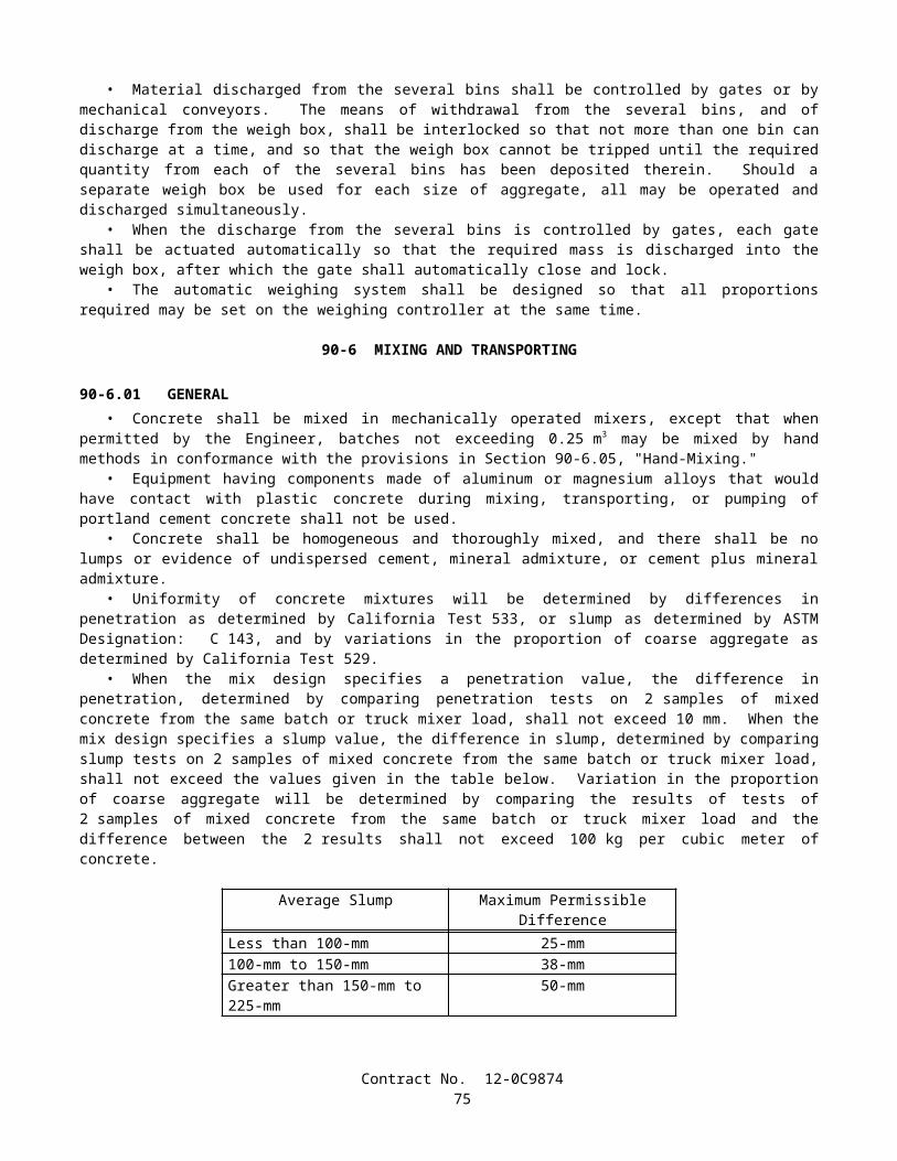
SUBSTITUTION TABLE FOR NOMINAL THICKNESS OF SHEET METALUNCOATED HOT AND COLD ROLLED SHEETS HOT-DIPPED ZINC COATED SHEETS
(GALVANIZED)METRIC THICKNESS
SHOWN ON THE PLANSmm
GAGE TO BE SUBSTITUTED
inch
METRIC THICKNESSSHOWN ON THE PLANS
mm
GAGE TO BE SUBSTITUTED
inch7.94 0.3125 4.270 0.16816.07 0.2391 3.891 0.15325.69 0.2242 3.510 0.13825.31 0.2092 3.132 0.12334.94 0.1943 2.753 0.10844.55 0.1793 2.372 0.09344.18 0.1644 1.994 0.07853.80 0.1495 1.803 0.07103.42 0.1345 1.613 0.06353.04 0.1196 1.461 0.05752.66 0.1046 1.311 0.05162.28 0.0897 1.158 0.04561.90 0.0747 1.006 or 1.016 0.03961.71 0.0673 0.930 0.03661.52 0.0598 0.853 0.03361.37 0.0538 0.777 0.03061.21 0.0478 0.701 0.02761.06 0.0418 0.627 0.02470.91 0.0359 0.551 0.02170.84 0.0329 0.513 0.02020.76 0.0299 0.475 0.01870.68 0.0269 -------- --------0.61 0.0239 -------- --------0.53 0.0209 -------- --------0.45 0.0179 -------- --------0.42 0.0164 -------- --------0.38 0.0149 -------- --------
Contract No. 12-0C987477

SUBSTITUTION TABLE FOR WIREMETRIC THICKNESS
SHOWN ON THE PLANSmm
WIRE THICKNESSTO BE SUBSTITUTED
inchGAGE NO.
6.20 0.244 35.72 0.225 45.26 0.207 54.88 0.192 64.50 0.177 74.11 0.162 83.76 0.148 93.43 0.135 103.05 0.120 112.69 0.106 122.34 0.092 132.03 0.080 141.83 0.072 151.57 0.062 161.37 0.054 171.22 0.048 181.04 0.041 190.89 0.035 20
SUBSTITUTION TABLE FOR PIPE PILESMETRIC SIZE
SHOWN ON THE PLANSmm x mm
SIZETO BE SUBSTITUTED
inch x inchPP 360 x 4.55 NPS 14 x 0.179PP 360 x 6.35 NPS 14 x 0.250PP 360 x 9.53 NPS 14 x 0.375PP 360 x 11.12 NPS 14 x 0.438PP 406 x 12.70 NPS 16 x 0.500
PP 460 x T NPS 18 x T"PP 508 x T NPS 20 x T"PP 559 x T NPS 22 x T"PP 610 x T NPS 24 x T"PP 660 x T NPS 26 x T"PP 711 x T NPS 28 x T"PP 762 x T NPS 30 x T"PP 813 x T NPS 32 x T"PP 864 x T NPS 34 x T"PP 914 x T NPS 36 x T"PP 965 x T NPS 38 x T"PP 1016 x T NPS 40 x T"PP 1067 x T NPS 42 x T"PP 1118 x T NPS 44 x T"PP 1219 x T NPS 48 x T"PP 1524 x T NPS 60 x T"
The thickness in millimeters (T) represents an exact conversion of the thickness in inches (T").
Contract No. 12-0C987478
SUBSTITUTION TABLE FOR STRUCTURAL TIMBER AND LUMBER METRIC MINIMUM
DRESSED DRY,SHOWN ON THE PLANS
mm x mm
METRIC MINIMUM DRESSED GREEN,
SHOWN ON THE PLANSmm x mm
NOMINAL SIZE
TO BE SUBSTITUTEDinch x inch
19x89 20x90 1x438x89 40x90 2x464x89 65x90 3x489x89 90x90 4x4
140x140 143x143 6x6140x184 143x190 6x8184x184 190x190 8x8235x235 241x241 10x10286x286 292x292 12x12
SUBSTITUTION TABLE FOR NAILS AND SPIKESMETRIC COMMON NAIL,SHOWN ON THE PLANS
Length, mmDiameter, mm
METRIC BOX NAIL,SHOWN ON THE PLANS
Length, mmDiameter, mm
METRIC SPIKE,SHOWN ON THE
PLANSLength, mm
Diameter, mm
SIZETO BE
SUBSTITUTEDPenny-weight
50.802.87
50.802.51
______ 6d
63.503.33
63.502.87
______ 8d
76.203.76
76.203.25
76.204.88
10d
82.553.76
82.553.25
82.554.88
12d
88.904.11
88.903.43
88.905.26
16d
101.604.88
101.603.76
101.605.72
20d
114.305.26
114.303.76
114.306.20
30d
127.005.72
127.004.11
127.006.68
40d
______ ______ 139.707.19
50d
______ ______ 152.407.19
60d
Contract No. 12-0C987479
SUBSTITUTION TABLE FOR IRRIGATION COMPONENTS
METRICWATER METERS, TRUCK LOADING STANDPIPES, VALVES, BACKFLOW PREVENTERS, FLOW
SENSORS, WYE STRAINERS, FILTER
ASSEMBLY UNITS, PIPE SUPPLY LINES, AND PIPE
IRRIGATION SUPPLY LINES
SHOWN ON THE PLANSDIAMETER NOMINAL
(DN) mm
NOMINAL SIZE
TO BE SUBSTITUTED
inch15 1/220 3/425 132 1-1/440 1-1/250 265 2-1/275 3100 4150 6200 8250 10300 12350 14400 16
Unless otherwise specified, substitutions of United States Standard Measures standard structural shapes corresponding to the metric designations shown on the plans and in conformance with the requirements in ASTM Designation: A 6/A 6M, Annex 2, will be allowed.
8-1.02 PREQUALIFIED AND TESTED SIGNING AND DELINEATION MATERIALSThe Department maintains the following list of Prequalified and Tested Signing and Delineation Materials. The
Engineer shall not be precluded from sampling and testing products on the list of Prequalified and Tested Signing and Delineation Materials.
The manufacturer of products on the list of Prequalified and Tested Signing and Delineation Materials shall furnish the Engineer a Certificate of Compliance in conformance with the provisions in Section 6-1.07, "Certificates of Compliance," of the Standard Specifications for each type of traffic product supplied.
For those categories of materials included on the list of Prequalified and Tested Signing and Delineation Materials, only those products shown within the listing may be used in the work. Other categories of products, not included on the list of Prequalified and Tested Signing and Delineation Materials, may be used in the work provided they conform to the requirements of the Standard Specifications.
Materials and products may be added to the list of Prequalified and Tested Signing and Delineation Materials if the manufacturer submits a New Product Information Form to the New Product Coordinator at the Transportation Laboratory. Upon a Departmental request for samples, sufficient samples shall be submitted to permit performance of required tests. Approval of materials or products will depend upon compliance with the specifications and tests the Department may elect to perform.
PAVEMENT MARKERS, PERMANENT TYPERetroreflective With Abrasion Resistant Surface (ARS)
A. Apex, Model 921AR (100 mm x 100 mm)
Contract No. 12-0C987480
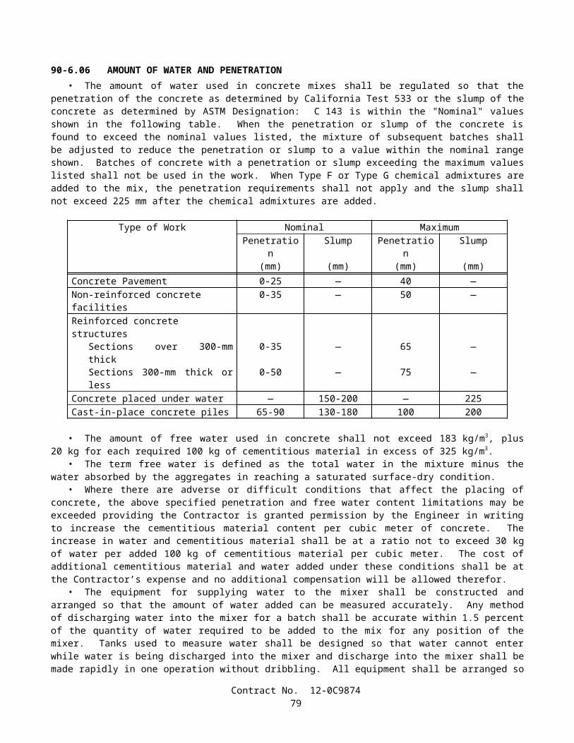
B. Avery Dennison (formerly Stimsonite), Models C88 (100 mm x 100 mm), 911 (100 mm x 100 mm) and 953 (70 mm x 114 mm)
C. Ray-O-Lite, Model "AA" ARS (100 mm x 100 mm)D. 3M Series 290 (89 mm x 100 mm)E. 3M Series 290 PSA, with pressure sensitive adhesive pad (89 mm x 100 mm)
Retroreflective With Abrasion Resistant Surface (ARS)(for recessed applications only)
A. Avery Dennison (formerly Stimsonite), Model 948 (58 mm x 119 mm)B. Avery Dennison (formerly Stimsonite), Model 944SB (51 mm x 100 mm)*C. Ray-O-Lite, Model 2002 (58 mm x 117 mm)D. Ray-O-Lite, Model 2004 ARS (51 mm x 100 mm)*
*For use only in 114 mm wide (older) recessed slots
Non-Reflective, 100 mm RoundA. Alpine Products, "D-Dot" and "ANR" (ABS)B. Apex Universal (Ceramic)C. Apex Universal, Models 929 (ABS) and 929PP (Polypropylene)D. Elgin Molded Plastics, "Empco-Lite" Model 900 (ABS)E. Glowlite (Ceramic)F. Hi-Way Safety, Inc., Models P20-2000W and 2001Y (ABS)G. Interstate Sales, "Diamond Back" (ABS) and (Polypropylene)H. Novabrite Models Cdot (White) Cdot-y (Yellow), CeramicI. Novabrite Models Adot-w (White) Adot-y (Yellow), (ABS)J. Novabrite Models Pdot-w (White) Pdot-y (Yellow), PolypropyleneK. Road Creations, Model RCB4NR (Acrylic)L. Three D Traffic Works TD10000 (ABS), TD10500 (Polypropylene)M. Zumar Industries, "Titan TM40A" (ABS)
PAVEMENT MARKERS, TEMPORARY TYPETemporary Markers For Long Term Day/Night Use (6 months or less)
A. Apex Universal, Model 924 (100 mm x 100 mm)B. Elgin Molded Plastics, "Empco-Lite" Model 901 (100 mm x 100 mm)C. Road Creations, Model R41C (100 mm x 100 mm)D. Vega Molded Products "Temporary Road Marker" (75 mm x 100 mm)
Temporary Markers For Short Term Day/Night Use (14 days or less)(For seal coat or chip seal applications, clear protective covers are required)
A. Apex Universal, Model 932B. Bunzl Extrusion, Models T.O.M., T.R.P.M., and "HH" (High Heat)C. Hi-Way Safety, Inc., Model 1280/1281
STRIPING AND PAVEMENT MARKING MATERIALPermanent Traffic Striping and Pavement Marking Tape
A. Advanced Traffic Marking, Series 300 and 400B. Brite-Line, Series 1000C. Brite-Line, "DeltaLine XRP"D. Swarco Industries, "Director 35" (For transverse application only)E. Swarco Industries, "Director 60"F. 3M, "Stamark" Series 380 and 5730G. 3M, "Stamark" Series 420 (For transverse application only)
Temporary (Removable) Striping and Pavement Marking Tape (6 months or less)A. Advanced Traffic Marking, Series 200B. Brite-Line, Series 100C. Garlock Rubber Technologies, Series 2000
Contract No. 12-0C987481
D. P.B. Laminations, Aztec, Grade 102E. Swarco Industries, "Director-2"F. Trelleborg Industri, R140 SeriesG. 3M, Series 620 "CR", and Series A750H. 3M, Series A145, Removable Black Line Mask
(Black Tape: for use only on Asphalt Concrete Surfaces)I. Advanced Traffic Marking Black "Hide-A-Line"
(Black Tape: for use only on Asphalt Concrete Surfaces)J. Brite-Line "BTR" Black Removable Tape
(Black Tape: for use only on Asphalt Concrete Surfaces)K. Trelleborg Industri, RB-140
(Black Tape: for use only on Asphalt Concrete Surfaces)
Preformed Thermoplastic (Heated in place)A. Avery Dennison, "Hotape"B. Flint Trading, "Premark," "Premark 20/20 Flex," and "Premark 20/20 Flex Plus"
Ceramic Surfacing Laminate, 150 mm x 150 mmA. Safeline Industries/Highway Ceramics, Inc.
CLASS 1 DELINEATORSOne Piece Driveable Flexible Type, 1700 mm
A. Bunzl Extrusion, "Flexi-Guide Models 400 and 566"B. Carsonite, Curve-Flex CFRM-400C. Carsonite, Roadmarker CRM-375D. FlexStake, Model 654 TME. GreenLine Models HWD1-66 and CGD1-66F. J. Miller Industries, Model JMI-375 (with soil anchor)
Special Use Type, 1700 mmA. Bunzl Extrusion, Model FG 560 (with 450 mm U-Channel base)B. Carsonite, "Survivor" (with 450 mm U-Channel base)C. Carsonite, Roadmarker CRM-375 (with 450 mm U-Channel base)D. FlexStake, Model 604E. GreenLine Models HWDU and CGD (with 450 mm U-Channel base)F. Impact Recovery Model D36, with #105 Driveable BaseG. Safe-Hit with 200 mm pavement anchor (SH248-GP1)H. Safe-Hit with 380 mm soil anchor (SH248-GP2) and with 450 mm soil anchor (SH248-GP3)
Surface Mount Type, 1200 mmA. Bent Manufacturing Company, Masterflex Model MF-180EX-48B. Carsonite, "Super Duck II"C. FlexStake, Surface Mount, Models 704 and 754 TMD. Impact Recovery Model D48, with #101 Fixed (Surface-Mount) BaseE. Three D Traffic Works "Channelflex" ID No. 522248W
CHANNELIZERSSurface Mount Type, 900 mm
A. Bent Manufacturing Company, Masterflex Models MF-360-36 (Round) and MF-180-36 (Flat)B. Bunzl Extrusion, Flexi-Guide Models FG300LD and FG300URC. Carsonite, "Super Duck" (Flat SDF-436, Round SDR-336)D. Carsonite, "Super Duck II" Model SDCF203601MB "The Channelizer"E. FlexStake, Surface Mount, Models 703 and 753 TMF. GreenLine, Model SMD-36G. Hi-Way Safety, Inc. "Channel Guide Channelizer" Model CGC36H. Impact Recovery Model D36, with #101 Fixed (Surface-Mount) Base
Contract No. 12-0C987482
I. Repo, Models 300 and 400J. Safe-Hit, Guide Post, Model SH236SMAK. The Line Connection, "Dura-Post" Model DP36-3 (Permanent)L. The Line Connection, "Dura-Post" Model DP36-3C (Temporary)M. Three D Traffic Works "Channelflex" ID No. 522053W
Lane Separation SystemA. Bunzl "Flexi-Guide (FG) 300 Curb System"B. Qwick Kurb, "Klemmfix Guide System"C. Recycled Technology, Inc. "Safe-Lane System"
CONICAL DELINEATORS, 1070 mm(For 700 mm Traffic Cones, see Standard Specifications)A. Bent Manufacturing Company "T-Top"B. Plastic Safety Systems "Navigator-42"C. Radiator Specialty Company "Enforcer"D. Roadmaker Company "Stacker"E. TrafFix Devices "Grabber"F. Three D Traffic Works "Ringtop" TD7000, ID No. 742143
OBJECT MARKERSType "K", 450 mm
A. Bunzl, Model FG318PEB. Carsonite, Model SMD 615C. FlexStake, Model 701 KMD. Repo, Models 300 and 400E. Safe-Hit, Model SH718SMAF. The Line Connection, Model DP21-4K
Type "K-4" / "Q" Object Markers, 600 mmA. Bent Manufacturing "Masterflex" Model MF-360-24B. Bunzl Extrusion, Model FG324PEC. Carsonite, Super Duck IID. FlexStake, Model 701KME. Repo, Models 300 and 400F. Safe-Hit, Models SH8 24SMA_WA and SH8 24GP3_WAG. The Line Connection, Model DP21-4QH. Three D Traffic Works "Q" Marker, ID No. 531702W
CONCRETE BARRIER MARKERS AND TEMPORARY RAILING (TYPE K) REFLECTORS
Impactable TypeA. ARTUK, "FB"B. Bunzl Extrusion, Models PCBM-12 and PCBM-T12C. Duraflex Corp., "Flexx 2020" and "Electriflexx"D. Hi-Way Safety, Inc., Model GMKRM100E. Plastic Safety Systems "BAM" Models OM-BARR and OM-BWARF. Sun-Lab Technology, "Safety Guide Light Model TM-5"G. Three D Traffic Works "Roadguide" 9304 Series, ID No. 903176 (One-Way), ID No. 903215 (Two-Way)
Non-Impactable TypeA. ARTUK, JD SeriesB. Plastic Safety Systems "BAM" Models OM-BITARW and OM-BITARAC. Vega Molded Products, Models GBM and JD
Contract No. 12-0C987483
METAL BEAM GUARD RAIL POST MARKERS(For use to the left of traffic)A. Bunzl Extrusion, "Mini" (75 mm x 254 mm)B. Creative Building Products, "Dura-Bull, Model 11201"C. Duraflex Corp., "Railrider"
CONCRETE BARRIER DELINEATORS, 400 mm(For use to the right of traffic)A. Bunzl Extrusion, Model PCBM T-16B. Safe-Hit, Model SH216RBMC. Sun-Lab Technology, "Safety Guide Light, Model TM16," (75 mm x 300 mm)D. Three D Traffic Works "Roadguide" ID No. 904364 (White), ID No. 904390 (Yellow)
CONCRETE BARRIER-MOUNTED MINI-DRUM (260 mm x 360 mm x 570 mm)A. Stinson Equipment Company "SaddleMarker"
SOUND WALL DELINEATOR(Applied vertically. Place top of 75 mm x 300 mm reflective element at 1200 mm above roadway)A. Bunzl Extrusion, PCBM S-36B. Sun-Lab Technology, "Safety Guide Light, Model SM12," (75 mm x 300 mm)
GUARD RAILING DELINEATOR(Place top of reflective element at 1200 mm above plane of roadway)
Wood Post Type, 686 mmA. Bunzl Extrusion, FG 427 and FG 527B. Carsonite, Model 427C. FlexStake, Model 102 GRD. GreenLine GRD 27E. J. Miller Model JMI-375GF. Safe-Hit, Model SH227GRDG. Three D Traffic Works "Guardflex" TD9100 Series, ID No. 510476
Steel Post TypeA. Carsonite, Model CFGR-327 with CFGRBK300 Mounting Bracket
RETROREFLECTIVE SHEETINGChannelizers, Barrier Markers, and Delineators
A. Avery Dennison T-6500 Series (Formerly Stimsonite, Series 6200) (For rigid substrate devices only)B. Avery Dennison WR-6100 SeriesC. Nippon Carbide, Flexible Ultralite Grade (ULG) IID. Reflexite, PC-1000 Metalized PolycarbonateE. Reflexite, AC-1000 AcrylicF. Reflexite, AP-1000 Metalized PolyesterG. Reflexite, Conformalight, AR-1000 Abrasion Resistant CoatingH. 3M, High Intensity
Traffic Cones, 330 mm SleevesA. Reflexite SB (Polyester), Vinyl or "TR" (Semi-transparent)
Traffic Cones, 100 mm and 150 mm SleevesA. Nippon Carbide, Flexible Ultralite Grade (ULG) IIB. Reflexite, Vinyl, "TR" (Semi-transparent) or "Conformalight"C. 3M Series 3840
Contract No. 12-0C987484
Barrels and DrumsA. Avery Dennison WR-6100B. Nippon Carbide, Flexible Ultralite Grade (ULG) IIC. Reflexite, "Conformalight", "Super High Intensity" or "High Impact Drum Sheeting"D. 3M Series 3810
Barricades: Type I, Medium-Intensity (Typically Enclosed Lens, Glass-Bead Element)A. American Decal, AdcoliteB. Avery Dennison, T-1500 and T-1600 seriesC. 3M Engineer Grade, Series 3170
Barricades: Type II, Medium-High-Intensity (Typically Enclosed Lens, Glass-Bead Element)A. Avery Dennison, T-2500 SeriesB. Kiwalite Type IIC. Nikkalite 1800 Series
Signs: Type II, Medium-High-Intensity (Typically Enclosed Lens, Glass-Bead Element)A. Avery Dennison, T-2500 SeriesB. Kiwalite, Type IIC. Nikkalite 1800 Series
Signs: Type III, High-Intensity (Typically Encapsulated Glass-Bead Element)A. Avery Dennison, T-5500 and T-5500A SeriesB. Nippon Carbide, Nikkalite Brand Ultralite Grade IIC. 3M Series 3870
Signs: Type IV, High-Intensity (Typically Unmetallized Microprismatic Element)A. Avery Dennison, T-6500 Series (Formerly Stimsonite Series 6200)B. Nippon Carbide, Crystal Grade, 94000 Series
Signs: Type VI, Elastomeric (Roll-Up) High-Intensity, without AdhesiveA. Avery Dennison, WU-6014B. Novabrite LLC, "Econobrite"C. Reflexite "Vinyl"D. Reflexite "SuperBright"E. Reflexite "Marathon"F. 3M Series RS34 (Orange) and RS20 (Fluorescent orange)
Signs: Type VII, Super-High-Intensity (Typically Unmetallized Microprismatic Element)A. 3M LDP Series 3924 (Fluorescent Red/Orange)B. 3M LDP Series 3970
Signs: Type VIII, Super-High-Intensity (Typically Unmetallized Microprismatic Element)A. Avery Dennison, T-7500 Series
Signs: Type IX, Very-High-Intensity (Typically Unmetallized Microprismatic Element)A. 3M VIP Series 3981 Diamond Grade (Fluorescent yellow)B. 3M VIP Series 3983 Diamond Grade (Fluorescent yellow/Green)C. 3M VIP Series 3990 Diamond
SPECIALTY SIGNSA. All Sign Products, STOP Sign (All Plastic), 750 mmB. Relexite "Endurance" Work Zone Sign (with Semi-Rigid Plastic Substrate)
Contract No. 12-0C987485

SIGN SUBSTRATEFiberglass Reinforced Plastic (FRP)
A. Fiber-BriteB. Sequentia, "Polyplate"C. Inteplast Group "InteCel" (13 mm for Post-Mounted CZ Signs, 1200 mm or less)
Aluminum CompositeA. Alcan Composites "Dibond Material, 2 mm" (for temporary construction signs only)B. Mitsubishi Chemical America, Alpolic 350 (for temporary construction signs only)
8-1.03 SLAG AGGREGATEAggregate produced from slag resulting from any steel-making process or from air-cooled iron blast furnace slag shall
not be used on this project.
8-1.04 STATE-FURNISHED MATERIALSAttention is directed to Section 6-1.02, "State-Furnished Materials," of the Standard Specifications and these special
provisions.Reclaimed water warning decals and aluminum sign plates will be furnished to the Contractor.
SECTION 8-2. CONCRETE
8-2.01 PORTLAND CEMENT CONCRETEPortland cement concrete shall conform to the provisions in Section 90, "Portland Cement Concrete," of the Standard
Specifications and these special provisions.References to Section 90-2.01, "Portland Cement," of the Standard Specifications shall mean Section 90-2.01, "Cement,"
of the Standard Specifications.Mineral admixture shall be combined with cement in conformance with the provisions in Section 90-4.08, "Required Use
of Mineral Admixtures," of the Standard Specifications for the concrete materials specified in Section 56-2, "Roadside Signs," of the Standard Specifications.
The requirements of Section 90-4.08, "Required Use of Mineral Admixture," of the Standard Specifications shall not apply to Section 19-3.025C, "Soil Cement Bedding," of the Standard Specifications.
The Department maintains a list of sources of fine and coarse aggregate that have been approved for use with a reduced amount of mineral admixture in the total amount of cementitious material to be used. A source of aggregate will be considered for addition to the approved list if the producer of the aggregate submits to the Transportation Laboratory certified test results from a qualified testing laboratory that verify the aggregate complies with the requirements. Prior to starting the testing, the aggregate test shall be registered with the Department. A registration number can be obtained by calling (916) 227-7228. The registration number shall be used as the identification for the aggregate sample in correspondence with the Department. Upon request, a split of the tested sample shall be provided to the Department. Approval of aggregate will depend upon compliance with the specifications, based on the certified test results submitted, together with any replicate testing the Department may elect to perform. Approval will expire 3 years from the date the most recent registered and evaluated sample was collected from the aggregate source.
Qualified testing laboratories shall conform to the following requirements:
A. Laboratories performing ASTM Designation: C 1293 shall participate in the Cement and Concrete Reference Laboratory (CCRL) Concrete Proficiency Sample Program and shall have received a score of 3 or better on all tests of the previous 2 sets of concrete samples.
B. Laboratories performing ASTM Designation: C 1260 shall participate in the Cement and Concrete Reference Laboratory (CCRL) Pozzolan Proficiency Sample Program and shall have received a score of 3 or better on the shrinkage and soundness tests of the previous 2 sets of pozzolan samples.
Aggregates on the list shall conform to one of the following requirements:
A. When the aggregate is tested in conformance with the requirements in California Test 554 and ASTM Designation: C 1293, the average expansion at one year shall be less than or equal to 0.040 percent; or
B. When the aggregate is tested in conformance with the requirements in California Test 554 and ASTM Designation: C 1260, the average of the expansion at 16 days shall be less than or equal to 0.15 percent.
Contract No. 12-0C987486
The amounts of cement and mineral admixture used in cementitious material shall be sufficient to satisfy the minimum cementitious material content requirements specified in Section 90-1.01, "Description," or Section 90-4.05, "Optional Use of Chemical Admixtures," of the Standard Specifications and shall conform to the following:
A. The minimum amount of cement shall not be less than 75 percent by mass of the specified minimum cementitious material content.
B. The minimum amount of mineral admixture to be combined with cement shall be determined using one of the following criteria:
1. When the calcium oxide content of a mineral admixture is equal to or less than 2 percent by mass, the amount of mineral admixture shall not be less than 15 percent by mass of the total amount of cementitious material to be used in the mix.
2. When the calcium oxide content of a mineral admixture is greater than 2 percent by mass, and any of the aggregates used are not listed on the approved list as specified in these special provisions, then the amount of mineral admixture shall not be less than 25 percent by mass of the total amount of cementitious material to be used in the mix.
3. When the calcium oxide content of a mineral admixture is greater than 2 percent by mass and the fine and coarse aggregates are listed on the approved list as specified in these special provisions, then the amount of mineral admixture shall not be less than 15 percent by mass of the total amount of cementitious material to be used in the mix.
4. When a mineral admixture that conforms to the provisions for silica fume in Section 90-2.04, "Admixture Materials," of the Standard Specifications is used, the amount of mineral admixture shall not be less than 10 percent by mass of the total amount of cementitious material to be used in the mix.
5. When a mineral admixture that conforms to the provisions for silica fume in Section 90-2.04, "Admixture Materials," of the Standard Specifications is used and the fine and coarse aggregates are listed on the approved list as specified in these special provisions, then the amount of mineral admixture shall not be less than 7 percent by mass of the total amount of cementitious material to be used in the mix.
C. The total amount of mineral admixture shall not exceed 35 percent by mass of the total amount of cementitious material to be used in the mix. Where Section 90-1.01, "Description," of the Standard Specifications specifies a maximum cementitious content in kilograms per cubic meter, the total mass of cement and mineral admixture per cubic meter shall not exceed the specified maximum cementitious material content.
The Contractor will be permitted to use Type III portland cement for concrete used in the manufacture of precast concrete members.
SECTION 8-3. WELDING
8-3.01 WELDINGGENERALFlux core welding electrodes conforming to the requirements of AWS A5.20 E6XT-4 or E7XT-4 shall not be used to
perform welding for this project.Wherever reference is made to the following AWS welding codes in the Standard Specifications, on the plans, or in these
special provisions, the year of adoption for these codes shall be as listed:
AWS Code Year of AdoptionD1.1 2002D1.4 1998D1.5 2002D1.6 1999
Requirements of the AWS welding codes shall apply unless specified otherwise in the Standard Specifications, on the plans, or in these special provisions. Wherever the abbreviation AWS is used, it shall be equivalent to the abbreviations ANSI/AWS or AASHTO/AWS.
Section 6.1.1.1 of AWS D1.5 is replaced with the following:
Contract No. 12-0C987487
Quality Control (QC) shall be the responsibility of the Contractor. As a minimum, the Contractor shall perform inspection and testing of each weld joint prior to welding, during welding, and after welding as specified in this section and as necessary to ensure that materials and workmanship conform to the requirements of the contract documents.
Sections 6.1.3 through 6.1.4.3 of AWS D1.1, Section 7.1.2 of AWS D1.4, and Sections 6.1.1.2 through 6.1.3.3 of AWS D1.5 are replaced with the following:
The QC Inspector shall be the duly designated person who acts for and on behalf of the Contractor for inspection, testing, and quality related matters for all welding.
Quality Assurance (QA) is the prerogative of the Engineer. The QA Inspector is the duly designated person who acts for and on behalf of the Engineer.
The QC Inspector shall be responsible for quality control acceptance or rejection of materials and workmanship, and shall be currently certified as an AWS Certified Welding Inspector (CWI) in conformance with the requirements in AWS QC1, " Standard for AWS Certification of Welding Inspectors."
The QC Inspector may be assisted by an Assistant QC Inspector provided that this individual is currently certified as an AWS Certified Associate Welding Inspector (CAWI) in conformance with the requirements in AWS QC1, "Standard for AWS Certification of Welding Inspectors." The Assistant QC Inspector may perform inspection under the direct supervision of the QC Inspector provided the Assistant is always within visible and audible range of the QC Inspector. The QC Inspector shall be responsible for signing all reports and for determining if welded materials conform to workmanship and acceptance criteria. The ratio of QC Assistants to QC Inspectors shall not exceed 5 to 1.
When the term "Inspector" is used without further qualification, it shall refer to the QC Inspector.
Section 6.14.6, "Personnel Qualification," of AWS D1.1, Section 7.8, "Personnel Qualification," of AWS D1.4, and Section 6.1.3.4, "Personnel Qualification," of AWS D1.5 are replaced with the following:
Personnel performing nondestructive testing (NDT) shall be qualified and certified in conformance with the requirements of the American Society for Nondestructive Testing (ASNT) Recommended Practice No. SNT-TC-1A and the Written Practice of the NDT firm. The Written Practice of the NDT firm shall meet or exceed the guidelines of the ASNT Recommended Practice No. SNT-TC-1A. Individuals who perform NDT, review the results, and prepare the written reports shall be either:
A. Certified NDT Level II technicians, or;B. Level III technicians who hold a current ASNT Level III certificate in that discipline and are authorized and certified
to perform the work of Level II technicians.
Section 6.5.4 of AWS D1.5 is replaced with the following:
The QC Inspector shall inspect and approve each joint preparation, assembly practice, welding technique, joint fit -up, and the performance of each welder, welding operator, and tack welder to make certain that the applicable requirements of this code and the approved Welding Procedure Specification (WPS) are met. The QC Inspector shall examine the work to make certain that it meets the requirements of Sections 3 and 6.26. The size and contour of all welds shall be measured using suitable gages. Visual inspection for cracks in welds and base metal, and for other discontinuities should be aided by strong light magnifiers, or such other devices as may be helpful. Acceptance criteria different from those specified in this code may be used when approved by the Engineer.
Section 6.6.5, "Nonspecified NDT Other than Visual," of AWS D1.1, Section 6.6.5 of AWS D1.4 and Section 6.6.5 of AWS D1.5 shall not apply.
For any welding, the Engineer may direct the Contractor to perform NDT that is in addition to the visual inspection or NDT specified in the AWS or other specified welding codes, in the Standard Specifications, or in these special provisions. Additional NDT required by the Engineer will be paid for as extra work as provided in Section 4-1.03D, "Extra Work," of the Standard Specifications. Should any welding deficiencies be discovered by this additional NDT, all costs associated with the repair of the deficient area, including NDT of the weld and of the weld repair, and any delays caused by the repair, shall be at the Contractor's expense.
Repair work to correct welding deficiencies discovered by visual inspection or NDT, or by additional NDT directed or performed by the Engineer, and any associated delays or expenses caused to the Contractor by performing these repairs, shall be at the Contractor's expense.
The Engineer shall have the authority to verify the qualifications or certifications of any welder, QC Inspector, or NDT personnel to specified levels by retests or other means approved by the Engineer.
Contract No. 12-0C987488
Continuous inspection shall be provided when any welding is being performed. Continuous inspection, as a minimum, shall include having a QC Inspector within such close proximity of all welders or welding operators so that inspections by the QC Inspector of each welding operation at each welding location shall not lapse for a period exceeding 30 minutes.
Inspection and approval of all joint preparations, assembly practices, joint fit-ups, welding techniques, and the performance of each welder, welding operator, and tack welder shall be documented by the QC Inspector on a daily basis for each day welding is performed. For each inspection, including fit-up, Welding Procedure Specification (WPS) verification, and final weld inspection, the QC Inspector shall confirm and document compliance with the requirements of the AWS or other specified code criteria and the requirements of these special provisions on all welded joints before welding, during welding, and after the completion of each weld.
When joint weld details that are not prequalified to the details of Section 3 of AWS D1.1 or to the details of Figure 2.4 or 2.5 of AWS D1.5 are proposed for use in the work, the joint details, their intended locations, and the proposed welding parameters and essential variables, will be approved by the Engineer. The Engineer shall have 2 weeks to complete the review of the proposed joint detail locations. In the event the Engineer fails to complete the review within the time allowed, and if, in the opinion of the Engineer, completion of the work is delayed or interfered with by reason of the Engineer's delay in completing the review, the Contractor will be compensated for any resulting loss, and an extension of time will be granted, in the same manner as provided for in Section 8-1.09, "Right of Way Delays," of the Standard Specifications. Upon approval of the proposed joint detail locations and qualification of the proposed joint details, welders and welding operators using these details shall perform a qualification test plate using the WPS variables and the joint detail to be used in production. The test plate shall have the maximum thickness to be used in production and a minimum length of 180 mm and minimum finish welded width 460 mm. The test plate shall be mechanically and radiographically tested. Mechanical and radiographic testing and acceptance criteria shall be as specified in the applicable AWS codes.
In addition to the requirements specified in the applicable code, the period of effectiveness for a welder's or welding operator's qualification shall be a maximum of 3 years for the same weld process, welding position, and weld type. If production welding will be performed without gas shielding, then qualification shall also be without gas shielding. Excluding welding of fracture critical members, a valid qualification at the beginning of work on a contract will be acceptable for the entire period of the contract, as long as the welder's or welding operator's work remains satisfactory.
The Engineer will witness all qualification tests for WPSs that were not previously approved by the Department. An approved independent third party will witness the qualification tests for welders or welding operators. The independent third party shall be a current CWI and shall not be employed by the contractor performing the welding. The Engineer shall have 2 weeks to review the qualifications and copy of the current certification of the independent third party. In the event the Engineer fails to complete the review within the time allowed, and if, in the opinion of the Engineer, completion of the work is delayed or interfered with by reason of the Engineer's delay in completing the review, the Contractor will be compensated for any resulting loss, and an extension of time will be granted, in the same manner as provided for in Section 8-1.09, "Right of Way Delays," of the Standard Specifications. The Contractor shall notify the Engineer one week prior to performing any qualification tests. Witnessing of qualification tests by the Engineer shall not constitute approval of the intended joint locations, welding parameters, or essential variables.
In addition to the requirements of AWS D1.5 Section 5.12 or 5.13, welding procedures qualification, for work welded in conformance with that code, shall conform to the following requirements:
A. Unless considered prequalified, fillet welds, including reinforcing fillet welds, shall be qualified in each position. The fillet weld soundness test shall be conducted using the essential variables of the WPS as established by the Procedure Qualification Record (PQR.)
B. For qualification of joints that do not conform to Figures 2.4 and 2.5 of AWS D1.5, two WPS qualification tests are required. The tests conforming to AWS D1.5 Section 5.13 shall be conducted using both Figure 5.1 and Figure 5.3. The test conforming to Figure 5.3 shall be conducted using the same welding electrical parameters that were established for the test conducted conforming to Figure 5.1.
C. The travel speed, current, and voltage values that are used for tests conducted per AWS D1.5 Section 5.12 or 5.13 shall be consistent for each weld joint, and shall in no case vary by more than 10 percent for travel speed, 10 percent for current, and 7 percent for voltage.
D. For a WPS qualified in conformance with AWS D1.5 Section 5.13, the values to be used for calculating ranges for current and voltage shall be based on the average of all weld passes made in the test. Heat input shall be calculated using the average of current and voltage of all weld passes made in the test for a WPS qualified in conformance with Section 5.12 or 5.13.
E. To qualify for unlimited material thickness, two qualification tests are required for WPSs utilized for welding material thicknesses greater than 38 mm. One test shall be conducted using 20-mm thick test plates, and one test shall be conducted using test plates with a thickness between 38 mm and 50 mm. Two maximum heat input tests may be conducted for unlimited thickness qualification.
F. Macroetch tests are required for WPS qualification tests, and acceptance shall be per AWS D1.5 Section 5.19.3.
Contract No. 12-0C987489
G. When a weld joint is to be made using a combination of qualified WPSs, each process shall be qualified separately.H. When a weld joint is to be made using a combination of qualified and prequalified processes, the WPS shall reflect
both processes and the limitations of essential variables, including weld bead placement, for both processes.I. Prior to preparing mechanical test specimens, the PQR welds shall be inspected by visual and radiographic tests.
Backing bar shall be 75 mm in width and shall remain in place during NDT testing. Results of the visual and radiographic tests shall comply with AWS D1.5 Section 6.26.2, excluding Section 6.26.2.2. Test plates that do not comply with both tests shall not be used.
PAYMENTFull compensation for conforming to the requirements of "Welding" shall be considered as included in the contract
prices paid for the various items of work involved and no additional compensation will be allowed therefor.
SECTION 9. (BLANK)
SECTION 10. CONSTRUCTION DETAILS
SECTION 10-1. GENERAL
10-1.01 ORDER OF WORKOrder of work shall conform to the provisions in Section 5-1.05, "Order of Work," of the Standard Specifications and
these special provisions.Temporary railing (Type K) and temporary crash cushions shall be secured in place prior to commencing work for which
the temporary railing and crash cushions are required.Attention is directed to "Water Pollution Control" of these special provisions regarding the submittal and approval of the
Storm Water Pollution Prevention Plan prior to performing work having potential to cause water pollution.Within 30 days after the contract has been approved, the Contractor shall furnish the Engineer a statement from the
vendor that the order for the seed required for this contract has been received and accepted by the vendor. The statement from the vendor shall include the names and quantity of seed ordered and the anticipated date of delivery.
Attention is directed to "Existing Highway Irrigation Facilities" of these special provisions regarding the checking of existing irrigation facilities that are to remain in place, prior to the start of any irrigation work.
Clearing, grubbing, and earthwork operations shall not be performed in areas where existing irrigation facilities are to remain in place until existing irrigation facilities have been checked for proper operation in conformance with the provisions in "Existing Highway Irrigation Facilities" of these special provisions.
Attention is directed to "Move-In/Move-Out (Erosion Control)" of these special provisions regarding the application of erosion control may require several move-in/move-outs of erosion control equipment.
10-1.02 WATER POLLUTION CONTROLWater pollution control work shall conform to the provisions in Section 7-1.01G, "Water Pollution," of the Standard
Specifications and these special provisions.This project lies within the boundaries of the Santa Ana and San Diego Regional Water Quality Control Board
(RWQCB).The State Water Resources Control Board (SWRCB) has issued a permit to the Department which governs storm water
and non-storm water discharges from its properties, facilities and activities. The Department's Permit is entitled: "Order No. 99-06-DWQ, NPDES No. CAS000003, National Pollutant Discharge Elimination System (NPDES) Permit, Storm Water Permit and Waste Discharge Requirements (WDRs) for the State of California, Department of Transportation Properties, Facilities, and Activities." Copies of the Department's Permit are available for review from the SWRCB, Storm Water Permit Unit, 1001 "I" Street, P.O. Box 1977, Sacramento, California 95812-1977, Telephone: (916) 341-5254, and may also be obtained from the SWRCB Internet website at: http://www.swrcb.ca.gov/stormwtr/caltrans.html.
The Department's Permit references and incorporates by reference the current Statewide General Permit issued by the SWRCB entitled "Order No. 99-08-DWQ, National Pollutant Discharge Elimination System (NPDES) General Permit No. CAS000002, Waste Discharge Requirements (WDRs) for Discharges of Storm Water Associated with Construction Activity," which regulates discharges of storm water and non-storm water from construction activities disturbing 0.4-hectare or more of soil in a common plan of development. Sampling and analysis requirements as specified in SWRCB Resolution No. 2001-46 are added to the Statewide General Permit. Copies of the Statewide General Permit and modifications thereto are available for review from the SWRCB, Storm Water Permit Unit, 1001 "I" Street, P.O. Box 1977, Sacramento, California 95812-1977, Telephone: (916) 341-5254 and may also be obtained from the SWRCB Internet website at: http://www.swrcb.ca.gov/stormwtr/construction.html.
Contract No. 12-0C987490

The NPDES permits that regulate this project, as referenced above, are hereafter collectively referred to as the "Permits."This project shall conform to the Permits and modifications thereto. The Contractor shall maintain copies of the Permits
at the project site and shall make the Permits available during construction.The Permits require the preparation of a Storm Water Pollution Prevention Plan (SWPPP). The SWPPP shall be
prepared in conformance with the requirements of the Permits, the Department's "Storm Water Pollution Prevention Plan (SWPPP) and Water Pollution Control Program (WPCP) Preparation Manual," and the Department's "Construction Site Best Management Practices (BMPs) Manual," including addenda to those permits and manuals issued up to and including the date of advertisement of the project. These manuals are hereinafter referred to, respectively, as the "Preparation Manual" and the "Construction Site BMPs Manual," and collectively, as the "Manuals." Copies of the Manuals may be obtained from the Department of Transportation, Material Operations Branch, Publication Distribution Unit, 1900 Royal Oaks Drive, Sacramento, California 95815, Telephone: (916) 445-3520, and may also be obtained from the Department's Internet website at: http://www.dot.ca.gov/hq/construc/stormwater/stormwater1.htm.
The Contractor shall know and fully comply with applicable provisions of the Permits and all modifications thereto, the Manuals, and Federal, State, and local regulations and requirements that govern the Contractor's operations and storm water and non-storm water discharges from both the project site and areas of disturbance outside the project limits during construction. Attention is directed to Sections 7-1.01, "Laws to be Observed," and 7-1.12, "Indemnification and Insurance," of the Standard Specifications.
The Permits shall apply to storm water and certain permitted non-storm water discharges from areas outside the project site which are directly related to construction activities for this contract including, but not limited to, asphalt batch plants, material borrow areas, concrete plants, staging areas, storage yards and access roads. The Contractor shall comply with the Permits and the Manuals for those areas and shall implement, inspect and maintain the required water pollution control practices. The Engineer shall be allowed full access to these areas during construction to assure Contractor's proper implementation of water pollution control practices. Installing, inspecting and maintaining water pollution control practices on areas outside the highway right of way not specifically arranged and provided for by the Department for the execution of this contract, will not be paid for.
The Contractor shall be responsible for penalties assessed or levied on the Contractor or the Department as a result of the Contractor's failure to comply with the provisions in this section "Water Pollution Control" including, but not limited to, compliance with the applicable provisions of the Permits, the Manuals, and Federal, State and local regulations and requirements as set forth therein.
Penalties as used in this section, "Water Pollution Control," shall include fines, penalties and damages, whether proposed, assessed, or levied against the Department or the Contractor, including those levied under the Federal Clean Water Act and the State Porter-Cologne Water Quality Control Act, by governmental agencies or as a result of citizen suits. Penalties shall also include payments made or costs incurred in settlement for alleged violations of the Permits, the Manuals, or applicable laws, regulations, or requirements. Costs incurred could include sums spent instead of penalties, in mitigation or to remediate or correct violations.
RETENTION OF FUNDSNotwithstanding any other remedies authorized by law, the Department may retain money due the Contractor under the
contract, in an amount determined by the Department, up to and including the entire amount of Penalties proposed, assessed, or levied as a result of the Contractor's violation of the Permits, the Manuals, or Federal or State law, regulations or requirements. Funds may be retained by the Department until final disposition has been made as to the Penalties. The Contractor shall remain liable for the full amount of Penalties until such time as they are finally resolved with the entity seeking the Penalties.
Retention of funds for failure to conform to the provisions in this section, "Water Pollution Control," shall be in addition to the other retention amounts required by the contract. The amounts retained for the Contractor's failure to conform to provisions in this section will be released for payment on the next monthly estimate for partial payment following the date when an approved SWPPP has been implemented and maintained, and when water pollution has been adequately controlled, as determined by the Engineer.
When a regulatory agency identifies a failure to comply with the Permits and modifications thereto, the Manuals, or other Federal, State or local requirements, the Department may retain money due the Contractor, subject to the following:
A. The Department will give the Contractor 30 days notice of the Department's intention to retain funds from partial payments which may become due to the Contractor prior to acceptance of the contract. Retention of funds from payments made after acceptance of the contract may be made without prior notice to the Contractor.
B. No retention of additional amounts out of partial payments will be made if the amount to be retained does not exceed the amount being withheld from partial payments pursuant to Section 9-1.06, "Partial Payments," of the Standard Specifications.
Contract No. 12-0C987491
C. If the Department has retained funds, and it is subsequently determined that the State is not subject to the entire amount of the Costs and Liabilities assessed or proposed in connection with the matter for which the retention was made, the Department shall be liable for interest on the amount retained for the period of the retention. The interest rate payable shall be 6 percent per annum.
During the first estimate period that the Contractor fails to conform to the provisions in this section, "Water Pollution Control," the Department may retain an amount equal to 25 percent of the estimated value of the contract work performed.
The Contractor shall notify the Engineer immediately upon request from the regulatory agencies to enter, inspect, sample, monitor, or otherwise access the project site or the Contractor's records pertaining to water pollution control work. The Contractor and the Department shall provide copies of correspondence, notices of violation, enforcement actions or proposed fines by regulatory agencies to the requesting regulatory agency.
STORM WATER POLLUTION PREVENTION PLAN PREPARATION, APPROVAL AND AMENDMENTSAs part of the water pollution control work, a Storm Water Pollution Prevention Plan (SWPPP) is required for this
contract. The SWPPP shall conform to the provisions in Section 7-1.01G, "Water Pollution," of the Standard Specifications, the requirements in the Manuals, the requirements of the Permits, and these special provisions. Upon the Engineer's approval of the SWPPP, the SWPPP shall be considered to fulfill the provisions in Section 7-1.01G, "Water Pollution," of the Standard Specifications for development and submittal of a Water Pollution Control Program.
No work having potential to cause water pollution, shall be performed until the SWPPP has been approved by the Engineer. Approval shall not constitute a finding that the SWPPP complies with applicable requirements of the Permits, the Manuals and applicable Federal, State and local laws, regulations, and requirements.
The Contractor shall designate a Water Pollution Control Manager. The Water Pollution Control Manager shall be responsible for the preparation of the SWPPP and required modifications or amendments, and shall be responsible for the implementation and adequate functioning of the various water pollution control practices employed. The Contractor may designate different Water Pollution Control Managers to prepare the SWPPP and to implement the water pollution control practices. The Water Pollution Control Managers shall serve as the primary contact for issues related to the SWPPP or its implementation. The Contractor shall submit to the Engineer a statement of qualifications, describing the training, previous work history and expertise of the individual selected by the Contractor to serve as Water Pollution Control Manager. The Water Pollution Control Manager shall have a minimum of 24 hours of formal storm water management training or certification as a Certified Professional in Erosion and Sediment Control (CPESC). The Engineer will reject the Contractor's submission of a Water Pollution Control Manager if the submitted qualifications are deemed to be inadequate.
The SWPPP shall apply to the areas within and those outside of the highway right of way that are directly related to construction operations including, but not limited to, asphalt batch plants, material borrow areas, concrete plants, staging areas, storage yards, and access roads.
The SWPPP shall incorporate water pollution control practices in the following categories:
A. Soil stabilization.B. Sediment control.C. Wind erosion control.D. Tracking control.E. Non-storm water management.F. Waste management and materials pollution control.
The following contract items of work shall be incorporated into the SWPPP as "Temporary Water Pollution Control Practices": Temporary Silt Fence, Temporary Gravel Bag Berm, Temporary Concrete Washout Facility, and Temporary Construction Entrance. The Contractor's attention is directed to the special provisions provided for Temporary Water Pollution Control Practices.
The following contract items of work, as shown on the project plans or as specified elsewhere in these special provisions, shall be identified in the SWPPP as permanent water pollution control practices: SWMP Detention Basins. These permanent water pollution control practices shall be constructed as specified in "Order of Work" of these special provisions, and utilized during the construction period. The Contractor shall maintain and protect the permanent water pollution control practices throughout the duration of the project and shall restore these controls to the lines, grades and condition shown on the plans prior to acceptance of the contract.
The SWPPP shall include, but not be limited to, the items described in the Manuals, Permits and related information contained in the contract documents. The SWPPP shall also include a copy of the following: De-Mimimus/De-Watering Discharge Permit (Order No. 2001-96, NPDES No. CAG919002) issued by the San Diego RWQCB.
The Contractor shall develop and include in the SWPPP the Sampling and Analysis Plan(s) as required by the Permits, and modifications thereto, and as required in "Sampling and Analytical Requirements" of this section.
Contract No. 12-0C987492
The Contractor shall develop a Water Pollution Control Schedule that describes the timing of grading or other work activities that could affect water pollution. The Water Pollution Control Schedule shall be updated by the Contractor to reflect changes in the Contractor's operations that would affect the necessary implementation of water pollution control practices.
The Contractor shall complete the "Construction Site BMPs Consideration Checklist" presented in the Preparation Manual and shall incorporate water pollution control practices into the SWPPP. Water pollution control practices include the "Minimum Requirements" and other Contractor-selected water pollution control practices from the "Construction Site BMPs Consideration Checklist" and the "Project-Specific Minimum Requirements" identified in the Water Pollution Control Cost Break-Down of this section.
Within 20 working days after the approval of the contract, the Contractor shall submit 3 copies of the draft SWPPP to the Engineer. The Engineer will have 10 working days to review the SWPPP. If revisions are required, as determined by the Engineer, the Contractor shall revise and resubmit the SWPPP within 10 working days of receipt of the Engineer's comments. The Engineer will have 5 working days to review the revisions. Upon the Engineer's approval of the SWPPP, 4 approved copies of the SWPPP, incorporating the required changes, shall be submitted to the Engineer. In order to allow construction activities to proceed, the Engineer may conditionally approve the SWPPP while minor revisions are being completed. In the event the Engineer fails to complete the review within the time allowed, and if, in the opinion of the Engineer, completion of the work is delayed or interfered with by reason of the Engineer's delay in completing the review, the Contractor will be compensated for resulting losses, and an extension of time will be granted, in the same manner as provided for in Section 8-1.09, "Right of Way Delays," of the Standard Specifications.
The Contractor shall prepare an amendment to the SWPPP when there is a change in construction activities or operations which may affect the discharge of pollutants to surface waters, ground waters, municipal storm drain systems, or when the Contractor's activities or operations violate a condition of the Permits, or when directed by the Engineer. Amendments shall identify additional water pollution control practices or revised operations, including those areas or operations not identified in the initially approved SWPPP. Amendments to the SWPPP shall be prepared and submitted for review and approval within a time approved by the Engineer, but in no case longer than the time specified for the initial submittal and review of the SWPPP.
The Contractor shall keep one copy of the approved SWPPP and approved amendments at the project site. The SWPPP shall be made available upon request by a representative of the Regional Water Quality Control Board, State Water Resources Control Board, United States Environmental Protection Agency, or the local storm water management agency. Requests by the public shall be directed to the Engineer.
COST BREAK-DOWNThe Contractor shall include a Water Pollution Control Cost Break-Down in the SWPPP which itemizes the contract
lump sum for water pollution control work. The Contractor shall use the Water Pollution Control Cost Break-Down provided in this section as the basis for the cost break-down submitted with the SWPPP. The Contractor shall use the Water Pollution Control Cost Break-Down to identify items, quantities and values for water pollution control work, excluding Temporary Water Pollution Control Practices for which there are separate bid items. The Contractor shall be responsible for the accuracy of the quantities and values used in the cost break-down submitted with the SWPPP. Partial payment for the item of water pollution control will not be made until the Water Pollution Control Cost Break-Down is approved by the Engineer.
Line items indicated in the Water Pollution Control Cost Break-Down in this section with a specified Estimated Quantity shall be considered "Project-Specific Minimum Requirements." The Contractor shall incorporate Project-Specific Minimum Requirements with Contractor-designated quantities and values into the Water Pollution Control Cost Break-Down submitted with the SWPPP.
Line items indicated in the Water Pollution Control Cost Break-Down in this section without a specified Estimated Quantity shall be considered by the Contractor for selection to meet the applicable "Minimum Requirements" as defined in the Manuals, or for other water pollution control work as identified in the "Construction Site BMPs Consideration Checklist" presented in the Preparation Manual. In the Water Pollution Control Cost Break-Down submitted with the SWPPP, the Contractor shall list only those water pollution control practices selected for the project, including quantities and values required to complete the work for those items.
The sum of the amounts for the items of work listed in the Water Pollution Control Cost Break -Down shall be equal to the contract lump sum price bid for water pollution control. Overhead and profit shall be included in the individual items listed in the cost break-down.
Contract No. 12-0C987493
WATER POLLUTION CONTROL COST BREAK-DOWN
Contract No. 12-0C9874
ITEM ITEM DESCRIPTION UNIT ESTIMATED QUANTITY VALUE AMOUNT
SS-3 Hydraulic Mulch M2
SS-4 Hydroseeding M2
SS-5 Soil Binders M2
SS-6 Straw Mulch M2
SS-7 Geotextiles, Plastic Covers & Erosion Control Blankets/Mats
M2
SS-8 Wood Mulching M2
SS-9 Earth Dikes/Drainage Swales & Lined Ditches
M
SS-10 Outlet Protection/Velocity Dissipation Devices EA
SS-11 Slope Drains EA
SS-12 Streambank Stabilization LS
SC-1 Silt Fence M
SC-2 Sediment/Desilting Basin EA
SC-3 Sediment Trap EA
SC-4 Check Dam EA
SC-5 Fiber Rolls M
SC-6 Gravel Bag Berm M
SC-7 Street Sweeping and Vacuuming LS
SC-8 Sandbag Barrier M
SC-9 Straw Bale Barrier M
SC-10 Storm Drain Inlet Protection EA
WE-1 Wind Erosion Control LS
TC-1 Stabilized Construction Entrance/Exit EA
TC-2 Stabilized Construction Roadway EA
TC-3 Entrance/Outlet Tire Wash EA
Contract No. 12-0C987494
ITEM ITEM DESCRIPTION UNIT ESTIMATED QUANTITY VALUE AMOUNT
NS-1 Water Conservation Practices LS
NS-2 Dewatering Operations EA
NS-3 Paving and Grinding Operations LS
NS-4 Temporary Stream Crossing EA
NS-5 Clear Water Diversion EA
NS-6 Illicit Connection/Illegal Discharge Detection and Reporting LS
NS-7 Potable Water/Irrigation LS
NS-8 Vehicle and Equipment Cleaning LS
NS-9 Vehicle and Equipment Fueling LS
NS-10 Vehicle and Equipment Maintenance LS
NS-11 Pile Driving Operations LS
NS-12 Concrete Curing LS
NS-13 Material and Equipment Use over Water LS
NS-14 Concrete Finishing LS
NS-15 Structure Demolition/Removal Over or Adjacent to Water
LS
WM-1 Material Delivery and Storage LS
WM-2 Material Use LS
WM-3 Stockpile Management LS
WM-4 Spill Prevention and Control LS
WM-5 Solid Waste Management LS
WM-6 Hazardous Waste Management LS
WM-7 Contaminated Soil Management LS
WM-8 Concrete Waste Management LS
WM-9 Sanitary/Septic Waste Management LS
WM-10 Liquid Waste Management LS
TOTAL ____________________
Contract No. 12-0C987495

Adjustments in the items of work and quantities listed in the approved cost break-down shall be made when required to address amendments to the SWPPP, except when the adjusted items are paid for as extra work.
No adjustment in compensation will be made to the contract lump sum price paid for water pollution control due to differences between the quantities shown in the approved cost break-down and the quantities required to complete the work as shown on the approved SWPPP. No adjustment in compensation will be made for ordered changes to correct SWPPP work resulting from the Contractor's own operations or from the Contractor's negligence.
The approved cost break-down will be used to determine partial payments during the progress of the work and as the basis for calculating the adjustment in compensation for the item of water pollution control due to increases or decreases of quantities ordered by the Engineer. When an ordered change increases or decreases the quantities of an approved cost break-down item, the adjustment in compensation will be determined in the same manner specified for increases and decreases in the quantity of a contract item of work in conformance with the provisions in Section 4-1.03B, "Increased or Decreased Quantities," of the Standard Specifications. If an ordered change requires a new item which is not on the approved cost break-down, the adjustment in compensation will be determined in the same manner specified for extra work in conformance with Section 4-1.03D, "Extra Work," of the Standard Specifications.
If requested by the Contractor and approved by the Engineer, changes to the water pollution control practices listed in the approved cost break-down, including addition of new water pollution control practices, will be allowed. Changes shall be included in the approved amendment of the SWPPP. If the requested changes result in a net cost increase to the lump sum price for water pollution control, an adjustment in compensation will be made without change to the water pollution control item. The net cost increase to the water pollution control item will be paid for as extra work as provided in Section 4-1.03D, "Extra Work," of the Standard Specifications.
SWPPP IMPLEMENTATIONUnless otherwise specified, upon approval of the SWPPP, the Contractor shall be responsible throughout the duration of
the project for installing, constructing, inspecting, maintaining, removing, and disposing of the water pollution control practices specified in the SWPPP and in the amendments. Unless otherwise directed by the Engineer, the Contractor's responsibility for SWPPP implementation shall continue throughout temporary suspensions of work ordered in conformance with the provisions in Section 8-1.05, "Temporary Suspension of Work," of the Standard Specifications. Requirements for installation, construction, inspection, maintenance, removal, and disposal of water pollution control practices shall conform to the requirements in the Manuals and these special provisions.
If the Contractor or the Engineer identifies a deficiency in the implementation of the approved SWPPP or amendments, the deficiency shall be corrected immediately unless requested by the Contractor and approved by the Engineer in writing, but shall be corrected prior to the onset of precipitation. If the Contractor fails to correct the identified deficiency by the date agreed or prior to the onset of precipitation, the project shall be in nonconformance with this section, "Water Pollution Control." Attention is directed to Section 5-1.01, "Authority of Engineer," of the Standard Specifications, and to "Retention of Funds" of this section for possible nonconformance penalties.
If the Contractor fails to conform to the provisions of this section, "Water Pollution Control," the Engineer may order the suspension of construction operations until the project complies with the requirements of this section.
Implementation of water pollution control practices may vary by season. The Construction Site BMPs Manual and these special provisions shall be followed for control practice selection of year-round, rainy season and non-rainy season water pollution control practices.
Year-Round Implementation RequirementsThe Contractor shall have a year-round program for implementing, inspecting and maintaining water pollution control
practices for wind erosion control, tracking control, non-storm water management, and waste management and materials pollution control.
The National Weather Service weather forecast shall be monitored and used by the Contractor on a daily basis. An alternative weather forecast proposed by the Contractor may be used if approved by the Engineer. If precipitation is predicted, the necessary water pollution control practices shall be deployed prior to the onset of the precipitation.
Disturbed soil areas shall be considered active whenever the soil disturbing activities have occurred, continue to occur or will occur during the ensuing 21 days. Non-active areas shall be protected as prescribed in the Construction Site BMPs Manual within 14 days of cessation of soil disturbing activities or prior to the onset of precipitation, whichever occurs first.
In order to provide effective erosion control, the Contractor may be directed by the Engineer to apply permanent erosion control in small or multiple units. The Contractor’s attention is directed to "Erosion Control (Type D)" and "Move-In/Move-Out (Erosion Control)" of these special provisions.
The Contractor shall implement, maintain and inspect the following temporary sediment control practices on a year-round basis. The listed practices shall remain in place until their use is no longer needed, as determined by the Engineer.
Contract No. 12-0C987496
YEAR-ROUNDSEDIMENT CONTROL PRACTICES LOCATION USED
Silt Fence Per Contractor's Water Pollution Control PlanGravel Bag Berm Per Contractor's Water Pollution Control PlanConcrete Washout Facility Per Contractor's Water Pollution Control PlanConstruction Entrance Per Contractor's Water Pollution Control Plan
Rainy Season Implementation RequirementsSoil stabilization and sediment control practices shall be provided throughout the rainy season, defined as between
October 1 and May 1.An implementation schedule of required soil stabilization and sediment control practices for disturbed soil areas shall be
completed no later than 20 days prior to the beginning of each rainy season. The implementation schedule shall identify the soil stabilization and sediment control practices and the dates when the implementation will be 25 percent, 50 percent and 100 percent complete, respectively. For construction activities beginning during the rainy season, the Contractor shall implement applicable soil stabilization and sediment control practices.
Throughout the defined rainy season, the active disturbed soil area of the project site shall be not more than 2 hectares. The Engineer may approve, on a case-by-case basis, expansions of the active disturbed soil area limit. Soil stabilization and sediment control materials shall be maintained on site sufficient to protect disturbed soil areas. A detailed plan for the mobilization of sufficient labor and equipment shall be maintained to deploy the water pollution control practices required to protect disturbed soil areas prior to the onset of precipitation.
Non-Rainy Season Implementation RequirementsThe non-rainy season shall be defined as days outside the defined rainy season. The Contractor's attention is directed to
the Construction Site BMPs Manual for soil stabilization and sediment control implementation requirements on disturbed soil areas during the non-rainy season. Disturbed soil areas within the project shall be protected in conformance with the requirements in the Construction Site BMPs Manual with an effective combination of soil stabilization and sediment control.
MAINTENANCETo ensure the proper implementation and functioning of water pollution control practices, the Contractor shall regularly
inspect and maintain the construction site for the water pollution control practices identified in the SWPPP. The construction site shall be inspected by the Contractor as follows:
A. Prior to a forecast storm.B. After a precipitation event which causes site runoff.C. At 24 hour intervals during extended precipitation events.D. Routinely, a minimum of once every two weeks outside of the defined rainy season.E. Routinely, a minimum of once every week during the defined rainy season.
The Contractor shall use the Storm Water Quality Construction Site Inspection Checklist provided in the Preparation Manual or an alternative inspection checklist provided by the Engineer. One copy of each site inspection record shall be submitted to the Engineer within 24 hours of completing the inspection.
REPORTING REQUIREMENTSReport of Discharges, Notices or Orders
If the Contractor identifies discharges into surface waters or drainage systems in a manner causing, or potentially causing, a condition of pollution, or if the project receives a written notice or order from a regulatory agency, the Contractor shall immediately inform the Engineer. The Contractor shall submit a written report to the Engineer within 7 days of the discharge event, notice or order. The report shall include the following information:
A. The date, time, location, nature of the operation, and type of discharge, including the cause or nature of the notice or order.
B. The water pollution control practices deployed before the discharge event, or prior to receiving the notice or order.C. The date of deployment and type of water pollution control practices deployed after the discharge event, or after
receiving the notice or order, including additional measures installed or planned to reduce or prevent reoccurrence.
Contract No. 12-0C987497
D. An implementation and maintenance schedule for affected water pollution control practices.
Report of First-Time Non-Storm Water DischargeThe Contractor shall notify the Engineer at least 3 days in advance of first-time non-storm water discharge events,
excluding exempted discharges. The Contractor shall notify the Engineer of the operations causing non-storm water discharges and shall obtain field approval for first-time non-storm water discharges. Non-storm water discharges shall be monitored at first-time occurrences and routinely thereafter.
Annual CertificationsBy June 15 of each year, the Contractor shall complete and submit an Annual Certification of Compliance, as contained
in the Preparation Manual, to the Engineer.
SAMPLING AND ANALYTICAL REQUIREMENTSThe Contractor is required to implement specific sampling and analytical procedures to determine whether BMPs
implemented on the construction site are:A. preventing pollutants that are known or should be known by permittees to occur on construction sites that are not
visually detectable in storm water discharges, to cause or contribute to exceedances of water quality objectives, and
Non-Visible PollutantsThe project has the potential to discharge non-visible pollutants in storm water from the construction site. Basins 583L,
659L and 696R discharge into Aliso Creek and then to the Pacific Ocean. Aliso Creek is listed for Bacteria Indicators, Phosphorus and Toxicity pursuant to Clean Water Act, Section 303(d). Basin 1032L discharges into Bonita Creek and then to San Diego Creek (Reach 1). San Diego Creek is listed for Fecal Coliform and Pesticides, pursuant to Clean Water Act, Section 303(d). The project SWPPP shall contain a Sampling and Analysis Plan (SAP) that describes the sampling and analysis strategy and schedule to be implemented on the project for monitoring non-visible pollutants in conformance with this section.
The SAP shall identify potential non-visible pollutants that are known or should be known to occur on the construction site associated with the following: (1) construction materials, wastes or operations; (2) known existing contamination due to historical site usage; or (3) application of soil amendments, including soil stabilization products, with the potential to alter pH or contribute toxic pollutants to storm water. Planned material and waste storage areas, locations of known existing contamination, and areas planned for application of soil amendments shall be shown on the SWPPP Water Pollution Control Drawings.
The SAP shall identify a sampling schedule for collecting a sample down gradient from the applicable non -visible pollutant source and a sufficiently large uncontaminated control sample during the first two hours of discharge from rain events during daylight hours which result in a sufficient discharge for sample collection. If run-on occurs onto the non-visible pollutant source, a run-on sample that is immediately down gradient of the run-on to the Department's right of way shall be collected. A minimum of 72 hours of dry weather shall occur between rain events to distinguish separate rain events.
The SAP shall state that water quality sampling will be triggered when any of the following conditions are observed during the required storm water inspections conducted before or during a rain event:
A. Materials or wastes containing potential non-visible pollutants are not stored under watertight conditions.B. Materials or wastes containing potential non-visible pollutants are stored under watertight conditions, but (1) a
breach, leakage, malfunction, or spill is observed; and (2) the leak or spill has not been cleaned up prior to the rain event; and (3) there is the potential for discharge of non-visible pollutants to surface waters or drainage system.
C. Construction activities, such as application of fertilizer, pesticide, herbicide, methyl methacrylate concrete sealant, or non-pigmented curing compound have occurred during a rain event or within 24 hours preceding a rain event, and there is the potential for discharge of pollutants to surface waters or drainage system.
D. Soil amendments, including soil stabilization products, with the potential to alter pH levels or contribute toxic pollutants to storm water runoff have been applied, and there is the potential for discharge of pollutants to surface waters or drainage system (unless independent test data are available that demonstrate acceptable concentration levels of non-visible pollutants in the soil amendment).
E. Storm water runoff from an area contaminated by historical usage of the site is observed to combine with storm water, and there is the potential for discharge of pollutants to surface waters or drainage system.
The SAP shall identify sampling locations for collecting down gradient and control samples, and the rationale for their selection. The control sampling location shall be selected where the sample does not come into contact with materials,
Contract No. 12-0C987498
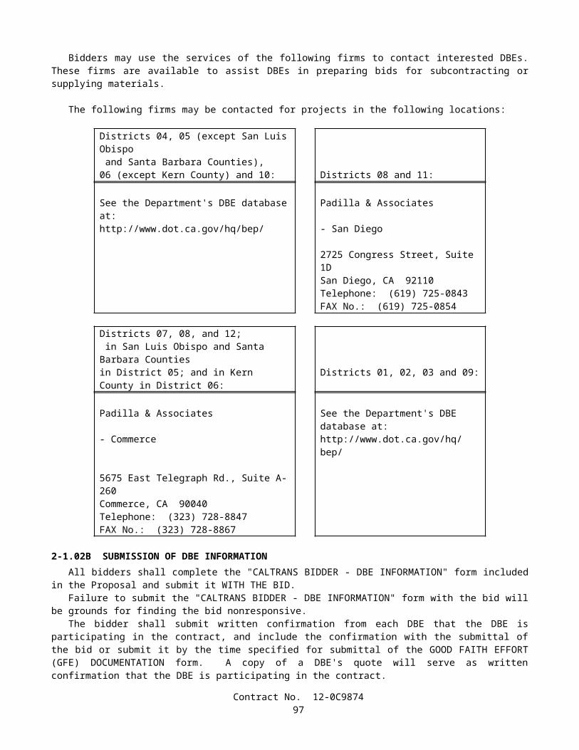
wastes or areas associated with potential non-visible pollutants or disturbed soil areas. Sampling locations shall be shown on the SWPPP Water Pollution Control Drawings. Only trained personnel shall collect water quality samples and be identified in the SAP. Qualifications of designated sampling personnel shall describe training and experience, and shall be included in the SWPPP. The SAP shall state monitoring preparation, sample collection procedures, quality assurance/quality control, sample labeling procedures, sample collection documentation, sample shipping and chain of custody procedures, sample numbering system, and reference the construction site health and safety plan.
The SAP shall identify the analytical method to be used for analyzing down gradient and control samples for potential non-visible pollutants on the project. For samples analyzed in the field by sampling personnel, collection, analysis, and equipment calibration shall be in conformance with the Manufacturer's specifications. For samples that will be analyzed by a laboratory, sampling, preservation, and analysis shall be performed by a State-certified laboratory in conformance with 40 CFR 136. The SAP shall identify the specific State-certified laboratory, sample containers, preservation requirements, holding times, and analysis method to be used. A list of State-certified laboratories that are approved by the Department is available at the following internet site: http://www.dhs.ca.gov/ps/ls/elap/html/lablist_county.htm.
Analytical Results and EvaluationThe Contractor shall submit a hard copy and electronic copy of water quality analytical results and quality
assurance/quality control data to the Engineer within 5 days of sampling for field analyses and within 30 days for laboratory analyses. Analytical results shall be accompanied by an evaluation from the Contractor to determine if down gradient samples show elevated levels of the tested parameter relative to levels in the control sample. If down gradient or downstream samples, as applicable, show increased levels, the Contractor will assess the BMPs, site conditions, and surrounding influences to determine the probable cause for the increase. As determined by the assessment, the Contractor will repair or modify BMPs to address increases and amend the SWPPP as necessary. Electronic results (in one of the following file formats: .xls, .txt, .csv, .dbs, or .mdb) shall have at a minimum the following information: sample identification number, contract number, constituent, reported value, method reference, method detection limit, and reported detection limit. The Contractor shall document sample collection during rain events.
Water quality sampling documentation and analytical results shall be maintained with the SWPPP on the project site until a Notice of Completion has been submitted and approved.
If construction activities or knowledge of site conditions change, such that discharges or sampling locations change, the Contractor shall amend the SAP in conformance with this section, "Water Pollution Control."
PAYMENTThe contract lump sum price paid for prepare storm water pollution prevention plan shall include full compensation for
furnishing all labor, materials, tools, equipment, and incidentals for doing all the work involved in developing, preparing, obtaining approval of, revising, and amending the SWPPP, as specified in the Standard Specifications and these special provisions, and as directed by the Engineer.
Attention is directed to Section 9-1.06, "Partial Payments," and Section 9-1.07, "Payment After Acceptance," of the Standard Specifications. Payments for prepare storm water pollution prevention plan will be made as follows:
A. After the SWPPP has been approved by the Engineer, 75 percent of the contract item price for prepare storm water pollution prevention plan will be included in the monthly partial payment estimate.
B. After acceptance of the contract in conformance with the provisions in Section 7-1.17, "Acceptance of Contract," of the Standard Specifications, payment for the remaining 25 percent of the contract item price for prepare storm water pollution prevention plan will be made in conformance with the provisions in Section 9-1.07.
The contract lump sum price paid for water pollution control shall include full compensation for furnishing all labor, materials, tools, equipment, and incidentals, and for doing all the work involved in installing, constructing, removing, and disposing of water pollution control practices, including non-storm water management, and waste management and materials pollution water pollution control practices, except those for which there is a contract item of work as specified in the Standard Specifications and these special provisions, and as directed by the Engineer.
Storm water sampling and analysis will be paid for as extra work as provided in Section 4-1.03D, "Extra Work," of the Standard Specifications. No payment will be made for the preparation, collection, analysis, and reporting of storm water samples required where appropriate BMPs are not implemented prior to a rain event, or if a failure of a BMP is not corrected prior to a rain event.
For items identified on the approved Water Pollution Control Cost Break-Down, the cost of maintaining the temporary water pollution control practices shall be divided equally by the State and the Contractor as follows:
Contract No. 12-0C987499
Soil StabilizationTemporary water pollution control practices except:
SS-1 SchedulingSS-2 Preservation of Existing Vegetation
Sediment ControlTemporary water pollution control practices except:
SC-7 Street Sweeping and Vacuuming
Wind Erosion ControlNo sharing of maintenance costs will be allowed.
Tracking ControlTC-1 Stabilized Construction Entrance/Exit.
Non-Storm Water ManagementNo sharing of maintenance costs will be allowed.
Waste Management & Materials Pollution ControlNo sharing of maintenance costs will be allowed.
The division of cost will be made by determining the cost of maintaining water pollution control practices in conformance with the provisions in Section 9-1.03, "Force Account Payment," of the Standard Specifications and paying to the Contractor one-half of that cost. Cleanup, repair, removal, disposal, improper installation, and replacement of water pollution control practices damaged by the Contractor's negligence, shall not be considered as included in the cost for performing maintenance.
The provisions for sharing maintenance costs shall not relieve the Contractor from the responsibility for providing appropriate maintenance on items with no shared maintenance costs.
Full compensation for non-shared maintenance costs of water pollution control practices, as specified in this section, "Water Pollution Control," shall be considered as included in the contract lump sum price paid for water pollution control and no additional compensation will be allowed therefor.
Water pollution control practices for which there is a contract item of work, will be measured and paid for as that contract item of work.
10-1.03 TEMPORARY CONCRETE WASHOUT FACILITYTemporary concrete washout facilities shall be constructed, maintained, and later removed at the locations shown on the
approved Storm Water Pollution Prevention Plan in conformance with "Water Pollution Control" of these special provisions, and in conformance with details shown on the plans and these special provisions.
Attention is directed to "Water Pollution Control" of these special provisions.Temporary concrete washout facilities shall be one of the water pollution control practices for waste management and
materials pollution control. The Storm Water Pollution Prevention Plan shall include the use of temporary concrete washout facilities.
MATERIALSPlastic Liner
Plastic liner shall be single ply, new polyethylene sheeting, a minimum of 0.25-mm thick and shall be free of holes, punctures, tears or other defects that compromise the impermeability of the material. Plastic liner shall not have seams or overlapping joints.
Gravel-filled BagsGravel bag fabric shall be non-woven polypropylene geotextile (or comparable polymer) and shall conform to the
following requirements:
Contract No. 12-0C9874100
Specification RequirementsMass per unit area, grams per square meter, min.ASTM Designation: D 5261
270
Grab tensile strength (25-mm grip), kilonewtons, min.ASTM Designation: D4632*
0.89
Ultraviolet stability, percent tensile strength retained after 500 hours,ASTM Designation: D4355, xenon arc lamp method
70
* or appropriate test method for specific polymer
Gravel bags shall be between 600 mm and 800 mm in length, and between 400 mm and 500 mm in width.Yarn used for binding gravel bags shall be as recommended by the manufacturer or bag supplier and shall be of a
contrasting color.Gravel shall be between 10 mm and 20 mm in diameter, and shall be clean and free from clay balls, organic matter, and
other deleterious materials.The opening of gravel-filled bags shall be secured to prevent gravel from escaping. Gravel-filled bags shall be between
13 kg and 22 kg in mass.
Straw BalesStraw for straw bales shall conform to the provisions in Section 20-2.06, "Straw," of the Standard Specifications.Straw bales shall be a minimum of 360 mm in width, 450 mm in height, 900 mm in length and shall have a minimum
mass of 23 kg. The straw bale shall be composed entirely of vegetative matter, except for binding material.Straw bales shall be bound by either wire, nylon or polypropylene string. Jute or cotton binding shall not be used.
Baling wire shall be a minimum 1.57 mm in diameter. Nylon or polypropylene string shall be approximately 2 mm in diameter with 360 N of breaking strength.
StakesStakes shall be wood or metal. Wood stakes shall be untreated fir, redwood, cedar, or pine, shall be cut from sound
timber, and shall be straight and free from loose or unsound knots and other defects which would render them unfit for the purpose intended. Wood stakes shall be minimum 50 mm x 50 mm in size. Metal stakes may be used as an alternative, and shall be a minimum 13 mm in diameter. Stakes shall be a minimum 1.2 m in length. The tops of the metal stakes shall be bent at a 90-degree angle or capped with an orange or red plastic safety cap that fits snugly to the metal stake. The Contractor shall submit a sample of the metal stake and plastic cap, if used, for Engineer's approval prior to installation.
StaplesStaples shall be as shown on the plans. An alternative attachment device such as geotextile pins or plastic pegs may be
used instead of staples. The Contractor shall submit a sample of the alternative attachment device for Engineer's approval prior to installation.
SignsWood posts for signs shall conform to the provisions in Section 56-2.02B, "Wood Posts," of the Standard Specifications.
Lag screws shall conform to the provisions in Section 56-2.02D, "Sign Panel Fastening Hardware," of the Standard Specifications.
Plywood shall be freshly painted for each installation with not less than 2 applications of flat white paint. Sign letters shown on the plans shall be stenciled with commercial quality exterior black paint. Testing of paint will not be required.
INSTALLATIONTemporary concrete washout facilities shall be as follows:
A. Temporary concrete washout facilities shall be installed prior to beginning placement of concrete and located a minimum of 15 m from storm drain inlets, open drainage facilities, and water courses unless determined infeasible by the Engineer. Temporary concrete washout facilities shall be located away from construction traffic or access areas at a location determined by the Contractor and approved by the Engineer.
B. A sign shall be installed adjacent to each washout facility at a location determined by the Contractor and approved by the Engineer. Signs shall be installed in conformance with the provisions in Section 56-2.03, "Construction," and Section 56-2.04, "Sign Panel Installation," of the Standard Specifications.
C. The length and width of a temporary concrete washout facility may be increased from the minimum dimensions shown on the plans, at the Contractor's expense and upon approval of the Engineer.
Contract No. 12-0C9874101
D. Temporary concrete washout facilities shall be constructed in sufficient quantity and size to contain liquid and concrete waste generated by washout operations for concrete wastes. These facilities shall be constructed to contain liquid and concrete waste without seepage, spillage or overflow.
E. Berms for below grade temporary concrete washout facilities shall be constructed from compacted native material. Gravel may be used in conjunction with compacted native material.
F. Plastic liner shall be installed in below grade temporary concrete washout facilities.
Details for an alternative temporary concrete washout facility shall be submitted to the Engineer for approval at least 7 days prior to installation.
When temporary concrete washout facilities are no longer required for the work, as determined by the Engineer, the hardened concrete and liquid residue shall be removed and disposed of in conformance with the provisions in Section 15-3.02, "Removal Methods," of the Standard Specifications. Temporary concrete washout facilities shall become the property of the Contractor and be disposed of in conformance with the provisions in Section 7-1.13, "Disposal of Material Outside the Highway Right of Way," of the Standard Specifications.
Ground disturbance, including holes and depressions, caused by the installation and removal of the temporary concrete washout facilities shall be backfilled and repaired in conformance with the provisions in Section 15-1.02, "Preservation of Property," of the Standard Specifications.
MAINTENANCETemporary concrete washout facilities shall be maintained to provide adequate holding capacity with a minimum
freeboard of 300 mm. Maintaining temporary concrete washout facilities shall include removing and disposing of hardened concrete and returning the facilities to a functional condition. Hardened concrete materials shall be removed and disposed of in conformance with the provisions in Section 15-3.02, "Removal Methods," of the Standard Specifications. Holes, rips, and voids in the plastic liner shall be patched and repaired by taping or the plastic liner shall be replaced. Plastic liner shall be replaced when patches or repairs compromise the impermeability of the material as determined by the Engineer.
Gravel bags shall be replaced when the bag material is ruptured or when the yarn has failed, allowing the bag contents to spill out.
Temporary concrete washout facility shall be repaired or replaced on the same day when the damage occurs. Damage to the temporary concrete washout facility resulting from the Contractor's vehicles, equipment, or operations shall be repaired at the Contractor’s expense.
MEASUREMENT AND PAYMENTThe quantity of temporary concrete washout facility to be paid for will be measured as unit determined from actual count
in place.The contract unit price paid for temporary concrete washout facility shall include full compensation for furnishing all
labor, materials, tools, equipment and incidentals, and for doing all the work involved in constructing temporary concrete washout facility, complete in place, including excavation and backfill, maintenance, and removal of temporary concrete washout facility, as shown on the plans, as specified in the Standard Specifications and these special provisions, and as directed by the Engineer.
No adjustment of compensation will be made for any increase or decrease in the quantities of temporary concrete washout facility required, regardless of the reason for the increase or decrease. The provisions in Section 4-1.03B, "Increased or Decreased Quantities," of the Standard Specifications shall not apply to temporary concrete washout facility.
10-1.04 TEMPORARY SILT FENCETemporary silt fence shall be furnished, installed, maintained, and later removed at the locations shown on the approved
Storm Water Pollution Prevention Plan in conformance with "Water Pollution Control" of these special provisions, and in conformance with details shown on the plans and these special provisions.
Attention is directed to "Water Pollution Control" of these special provisions.Temporary silt fence shall be one of the water pollution control practices for sediment control. The Storm Water
Pollution Prevention Plan shall include the use of temporary silt fence.
MATERIALSAt the Contractor's option, temporary silt fence shall be prefabricated or constructed with silt fence fabric, posts, and
fasteners.
Contract No. 12-0C9874102
Silt Fence FabricSilt fence fabric shall be geotextile manufactured from woven polypropylene or polymer material. Silt Fence Fabric may
be virgin or recycled, or a combination of virgin and recycled polymer materials. No virgin or recycled polymer materials shall contain biodegradable filler materials that can degrade the physical or chemical characteristics of the finished fabric. The Engineer may order tests to confirm the absence of biodegradable filler materials in conformance to the requirements in ASTM Designation: E 204 (Fourier Transformed Infrared Spectroscopy-FTIR).
Silt fence fabric shall conform to the following requirements:
Specification RequirementsWidth, mm, min. 900Grab tensile strength (25-mm grip), kilonewtons, min. in each directionASTM Designation: D 4632*
0.55
Elongation, percent minimum in each directionASTM Designation: D 4632*
15
Permittivity, 1/sec., min.ASTM Designation: D 4491
0.05
Flow rate, liters per minute per square meter, min.ASTM Designation: D 4491
400
Ultraviolet stability, percent tensile strength retained after 500 hours, min.ASTM Designation: D 4355 (xenon-arc lamp and water spray weathering method)
70
* or appropriate test method for specific polymer
PostsPosts for temporary silt fence shall be one of the following:
A. Posts shall be untreated fir or pine, minimum 34 mm x 40 mm in size, and 1.2 m in length. One end of the post shall be pointed.
B. Posts shall be steel and have a "U", "T", "L" or other cross sectional shape that can resist failure by lateral loads. The steel posts shall have a minimum mass per length of 1.1 kg/m and a minimum length of 1.2 m. One end of the steel posts shall be pointed and the other end shall be capped with an orange or red plastic safety cap which fits snugly to the steel post. The Contractor shall submit to the Engineer for approval a sample of the capped steel post prior to installation.
FastenersFasteners for attaching silt fence fabric to posts shall be as follows:
A. When prefabricated silt fence is used, posts shall be inserted into sewn pockets.B. Silt fence fabric shall be attached to wooden posts with nails or staples as shown on the plans or as recommended by
the manufacturer or supplier. Tie wire or locking plastic fasteners shall be used to fasten the silt fence fabric to steel posts. Maximum spacing of fasteners shall be 200 mm along the length of the steel post.
INSTALLATIONTemporary silt fence shall be installed parallel with the slope contour in reaches not to exceed 150 m. A reach is
considered a continuous run of temporary silt fence from end to end or from an end to an opening, including joined panels. Each reach shall be constructed so that the elevation at the base of the fence does not deviate from the contour more than one third of the fence height.
The silt fence fabric shall be installed on the side of the posts facing the slope. The silt fence fabric shall be anchored in a trench as shown on the plans. The trench shall be backfilled and mechanically or hand tamped to secure the silt fence fabric in the bottom of the trench.
Mechanically pushing 300 mm of the silt fence fabric vertically through the soil may be allowed if the Contractor can demonstrate to the Engineer that the silt fence fabric will not be damaged and will not slip out of the soil, resulting in sediment passing under the silt fence fabric.
At the option of the Contractor, the maximum post spacing may increase to 3 m if the fence is reinforced by a wire or plastic material by prefabrication or by field installation. The field-assembled reinforced temporary silt fence shall be able to retain saturated sediment without collapsing.
Contract No. 12-0C9874103
Temporary silt fence shall be joined as shown on the plans. The tops of the posts shall be tied together by minimum of 2 wraps of tie wire of a minimum 1.5 mm diameter. The silt fence fabric shall be attached to the posts at the joint as specified in these special provisions.
Temporary silt fence shall be repaired or replaced at the expense of the Contractor on the same day when the damage occurs.
When no longer required as determined by the Engineer, temporary silt fence shall become the property of the Contractor and be removed and disposed of in conformance with the provisions in Section 7-1.13, "Disposal of Material Outside the Highway Right of Way," of the Standard Specifications. Trimming the silt fence fabric and leaving it in place will not be allowed.
Ground disturbance, including holes and depressions, caused by the installation and removal of the temporary silt fence shall be backfilled and repaired in conformance with the provisions in Section 15-1.02, "Preservation of Property," of the Standard Specifications.
MAINTENANCETemporary silt fence shall be maintained to provide a sediment holding capacity of approximately one-third the height of
the silt fence fabric above ground. When sediment exceeds this height, or when directed by the Engineer, sediment shall be removed. The removed sediment shall be deposited within the project limits in such a way that the sediment is not subject to erosion by wind or by water.
Temporary silt fence shall be repaired or replaced on the same day when the damage occurs. Damage to the temporary silt fence resulting from the Contractor's vehicles, equipment, or operations shall be repaired at the Contractor’s expense.
MEASUREMENT AND PAYMENTThe quantity of temporary silt fence to be paid for will be measured by the meter, parallel with the ground slope along
the line of the installed temporary silt fence, deducting the widths of openings.The contract price paid per meter for temporary silt fence shall include full compensation for furnishing all labor,
materials, tools, equipment, and incidentals, and for doing all the work involved in installing temporary silt fence, complete in place, including trench excavation and backfill, maintenance, and removal of temporary silt fence, as shown on the plans, as specified in the Standard Specifications and these special provisions, and as directed by the Engineer.
No adjustment of compensation will be made for any increase or decrease in the quantities of temporary silt fence required, regardless of the reason for the increase or decrease. The provisions in Section 4-1.03B, "Increased or Decreased Quantities," of the Standard Specifications shall not apply to temporary silt fence.
10-1.05 PRESERVATION OF PROPERTYAttention is directed to Section 7-1.11, "Preservation of Property," of the Standard Specifications and these special
provisions.Existing trees, shrubs and other plants, that are not to be removed as shown on the plans or specified in these special
provisions, and are injured or damaged by reason of the Contractor's operations, shall be replaced by the Contractor. The minimum size of tree replacement shall be 600 mm box and the minimum size of shrub replacement shall be No. 15 container. Replacement ground cover plants shall be from flats and shall be planted 300 mm on center. Replacement of Carpobrotus ground cover plants shall be from cuttings and shall be planted 300 mm on center. Replacement planting shall conform to the requirements in Section 20-4.07, "Replacement," of the Standard Specifications. The Contractor shall water replacement plants in conformance with the provisions in Section 20-4.06, "Watering," of the Standard Specifications.
Damaged or injured plants shall be removed and disposed of outside the highway right of way in conformance with the provisions in Section 7-l.13 of the Standard Specifications. At the option of the Contractor, removed trees and shrubs may be reduced to chips. The chipped material shall be spread within the highway right of way at locations designated by the Engineer.
Replacement planting of injured or damaged trees, shrubs and other plants shall be completed not less than 20 working days prior to acceptance of the contract. Replacement plants shall be watered as necessary to maintain the plants in a healthy condition.
10-1.06 TEMPORARY GRAVEL BAG BERMTemporary gravel bag berm shall be furnished, installed, maintained, and later removed at the locations shown on the
approved Storm Water Pollution Prevention Plan in conformance with "Water Pollution Control" of these special provisions, and in conformance with details shown on the plans and these special provisions.
Attention is directed to "Water Pollution Control" of these special provisions.Temporary gravel bag berm shall be one of the water pollution control practices for sediment control. The Storm Water
Pollution Prevention Plan shall include the use of temporary gravel bag berm.
Contract No. 12-0C9874104
MATERIALSGravel-filled Bags
Gravel bag fabric shall be non-woven polypropylene geotextile (or comparable polymer) and shall conform to the following requirements:
Specification RequirementsMass per unit area, grams per square meter, min.ASTM Designation: D 5261
270
Grab tensile strength (25-mm grip), kilonewtons, min.ASTM Designation: D4632*
0.89
Ultraviolet stability, percent tensile strength retained after 500 hours,ASTM Designation: D4355, xenon arc lamp method
70
* or appropriate test method for specific polymer
Gravel bags shall be between 600 mm and 800 mm in length, and between 400 mm and 500 mm in width.Yarn used for binding gravel bags shall be as recommended by the manufacturer or bag supplier and shall be of a
contrasting color.Gravel shall be between 10 mm and 20 mm in diameter, and shall be clean and free from clay balls, organic matter, and
other deleterious materials. The opening of gravel-filled bags shall be secured to prevent gravel from escaping. Gravel-filled bags shall be between 13 kg and 22 kg in mass.
INSTALLATIONTemporary gravel bag berm shall be installed as follows:
A. Temporary gravel bag berm shall consist of a single layer of gravel bags placed with ends abutted tightly and not overlapped.
B. The bedding area for the temporary gravel bag berm shall be cleared of obstructions, including rocks, clods, and debris greater than 25 mm in diameter, prior to installation.
C. Temporary gravel bag berm shall be installed approximately parallel to the slope contour.D. The last 2 m of the temporary gravel bag berm shall be angled up-slope.
When no longer required, as determined by the Engineer, temporary gravel bag berm shall become the property of the Contractor, and shall be removed and disposed of in conformance with the provisions in Section 7-1.13, "Disposal of Material Outside the Highway Right of Way," of the Standard Specifications.
Ground disturbance, including holes and depressions, caused by the installation and removal of the temporary gravel bag berm shall be backfilled and repaired in conformance with the provisions in Section 15-1.02, "Preservation of Property," of the Standard Specifications.
MAINTENANCETemporary gravel bag berm shall be maintained to provide a sediment holding capacity of approximately one-third the
height of the gravel bag berm above the ground. When sediment exceeds this height, or when directed by the Engineer, sediment shall be removed. Removed sediment shall be deposited within the project limits in such a way that the sediment is not subject to erosion by wind or by water.
Temporary gravel bag berm shall be repaired or replaced on the same day when the damage occurs. Damage to the temporary gravel bag berm resulting from the Contractor's vehicles, equipment, or operations shall be repaired at the Contractor’s expense.
Gravel bags shall be replaced when the bag material is ruptured or when the yarn has failed, allowing the bag contents to spill out.
MEASUREMENT AND PAYMENTThe quantity of temporary gravel bag berm to be paid for will be measured by the meter, along the centerline of the
installed temporary gravel bag berm.The contract price paid per meter for temporary gravel bag berm shall include full compensation for furnishing all labor,
materials, tools, equipment, and incidentals, and for doing all the work involved in installing temporary gravel bag berm, complete in place, including backfill, maintenance, and removal of temporary gravel bag berm, as shown on the plans, as specified in the Standard Specifications and these special provisions, and as directed by the Engineer.
Contract No. 12-0C9874105
No adjustment of compensation will be made for any increase or decrease in the quantities of temporary gravel bag berm required, regardless of the reason for the increase or decrease. The provisions in Section 4-1.03B, "Increased or Decreased Quantities," of the Standard Specifications shall not apply to temporary gravel bag berm.
10-1.07 TEMPORARY CONSTRUCTION ENTRANCETemporary construction entrance shall be constructed, maintained, and later removed at the locations shown on the
approved Storm Water Pollution Prevention Plan in conformance with "Water Pollution Control" of these special provisions, and in conformance with details shown on the plans and these special provisions.
Attention is directed to "Water Pollution Control" of these special provisions.Temporary construction entrance shall be one of the water pollution control practices for tracking control. The Storm
Water Pollution Prevention Plan shall include the use of temporary construction entrance.At the option of the Contractor, temporary construction entrance shall be Type 1 or Type 2 .
MATERIALSTemporary Entrance Fabric
Temporary entrance fabric shall be manufactured from polyester, nylon or polypropylene material or any combination thereof. Temporary entrance fabric shall be a nonwoven, needle-punched fabric, free of any needles which may have broken off during the manufacturing process. Temporary entrance fabric shall be permeable and shall not act as a wicking agent.
Temporary entrance fabric shall be manufactured from virgin or recycled, or a combination of virgin and recycled, polymer materials. No virgin or recycled materials shall contain biodegradable filler materials that can degrade the physical or chemical characteristics of the finished fabric. The Engineer may order tests to confirm the absence of biodegradable filler materials in conformance to the requirements in ASTM Designation: E 204 (Fourier Transformed Infrared Spectroscopy-FTIR).
Temporary entrance fabric shall conform to the following requirements:
Specification RequirementsMass per unit area, grams per square meter, min.ASTM Designation: D 5261
235
Grab tensile strength (25-mm grip), kilonewtons, min.ASTM Designation: D4632*
0.89
Elongation at break, percent min.ASTM Designation: D4632*
50
Toughness, kilonewtons, min.(percent elongation x grab tensile strength)
53
* or appropriate test method for specific polymer
RocksRocks shall be angular to subangular in shape, and shall conform to the material quality requirements in Section 72-2.02,
"Materials," of the Standard Specifications for apparent specific gravity, absorption, and durability index. Rocks used for the temporary entrance shall conform to the following sizes:
Square Screen Size (mm)
Percentage Passing
150 10075 0-20
Corrugated Steel PanelsCorrugated steel panels shall be prefabricated and shall be pressed or shop welded, with a slot or hooked section to
facilitate coupling at the ends of the panels.
INSTALLATIONTemporary construction entrance shall be installed as follows:
A. Prior to placing the temporary entrance fabric, the areas shall be cleared of all trash and debris. Vegetation shall be removed to the ground level. Trash, debris, and removed vegetation shall be disposed of in conformance with the
Contract No. 12-0C9874106
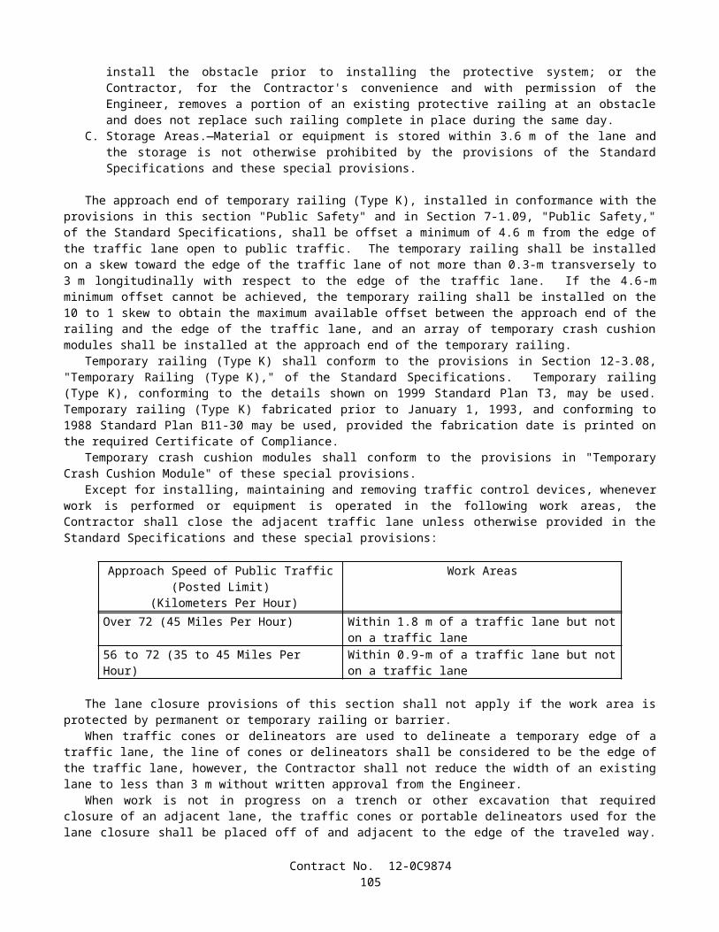
provisions in Section 7-1.13, "Disposal of Material Outside the Highway Right of Way," of the Standard Specifications.
B. A sump shall be constructed within 6 m of each temporary construction entrance as shown on the plans. The exact location of the sump will be determined by the Engineer.
C. Before placing the temporary entrance fabric, the ground shall be graded to a uniform plane. The relative compaction of the top 0.5-m shall be not less than 90 percent. The ground surface shall be free of sharp objects that may damage the temporary entrance fabric, and shall be graded to drain to the sump as shown on the plans.
D. Temporary entrance fabric shall be positioned longitudinally along the alignment of the entrance, as directed by the Engineer.
E. The adjacent ends of the fabric shall be overlapped a minimum length of 300 mm.F. Rocks to be placed directly over the fabric shall be spread in the direction of traffic, longitudinally and along the
alignment of the temporary construction entrance.G. During spreading of the rocks, vehicles or equipment shall not be driven directly on the fabric. A layer of rocks of
minimum 150 mm thick shall be placed between the fabric and the spreading equipment to prevent damage to the fabric.
H. For Type 2 temporary construction entrance, a minimum of 6 coupled panel sections shall be installed for each temporary construction entrance. Prior to installing the panels, the ground surface shall be cleared of all debris to ensure uniform contact with the ground surface.
Fabric damaged during rock placement shall be repaired by placing a new piece of fabric over the damaged area. The piece of fabric shall be large enough to cover the damaged area and provide a minimum 450-mm overlap on all edges.
Details for alternative temporary construction entrance shall be submitted to the Engineer for approval at least 7 days prior to installation.
If buildup of soil and sediment deter the function of the temporary construction entrance, the Contractor shall immediately remove and dispose of the soil and sediment, and install additional corrugated steel panels and spread additional rocks to increase the capacity of the temporary construction entrance at the Contractor's expenses.
When no longer required as determined by the Engineer, temporary construction entrances shall become the property of the Contractor and be removed and disposed of in conformance with the provisions in Section 7-1.13, "Disposal of Material Outside the Highway Right of Way," of the Standard Specifications.
Ground disturbance, including holes and depressions, caused by the installation and removal of the temporary construction entrance, including the sumps, shall be backfilled and repaired in conformance with the provisions in Section 15-1.02, "Preservation of Property," of the Standard Specifications.
While the temporary construction entrance is in use, pavement shall be cleaned and sediment removed at least once a day, and as often as necessary when directed by the Engineer. Soil and sediment or other extraneous material tracked onto existing pavement shall not be allowed to enter drainage facilities.
MAINTENANCEThe Contractor shall maintain temporary construction entrance throughout the contract or until removed. The Contractor
shall prevent displacement or migration of the rock surfacing or corrugated steel panels. Any significant depressions resulted from settlement or heavy equipment shall be repaired by the Contractor, as directed by the Engineer.
Temporary construction entrance shall be maintained to minimize tracking of soil and sediment onto existing public roads.
Temporary construction entrance shall be repaired or replaced on the same day when the damage occurs. Damage to the temporary construction entrance resulting from the Contractor's vehicles, equipment, or operations shall be repaired at the Contractor’s expense.
MEASUREMENT AND PAYMENTThe quantity of temporary construction entrance to be paid for will be measured as unit determined from actual count in
place.The contract unit price paid for temporary construction entrance shall include full compensation for furnishing all labor,
materials, tools, equipment, and incidentals, and for doing all the work involved in constructing temporary construction entrance, complete in place, including excavation and backfill, maintenance, and removal of temporary construction entrance, as shown on the plans, as specified in the Standard Specifications and these special provisions, and as directed by the Engineer.
No adjustment of compensation will be made for any increase or decrease in the quantities of temporary construction entrance required, regardless of the reason for the increase or decrease. The provisions in Section 4-1.03B, "Increased or Decreased Quantities," of the Standard Specifications shall not apply to temporary construction entrance.
Contract No. 12-0C9874107
10-1.08 PROGRESS SCHEDULE (CRITICAL PATH METHOD)The Contractor shall submit to the Engineer practicable critical path method (CPM) progress schedules in conformance
with these special provisions. Whenever the term "schedule" is used in this section it shall mean CPM progress schedule.The provisions in Section 8-1.04, "Progress Schedule," of the Standard Specifications shall not apply.
DEFINITIONSThe following definitions shall apply to this section:
A. ACTIVITY.—A task, event or other project element on a schedule that contributes to completing the project. Activities have a description, start date, finish date, duration and one or more logic ties.
B. BASELINE SCHEDULE.—The initial schedule representing the Contractor's work plan on the first working day of the project.
C. CONTRACT COMPLETION DATE.—The current extended date for completion of the contract shown on the weekly statement of working days furnished by the Engineer in conformance with the provisions in Section 8-1.06, "Time of Completion," of the Standard Specifications.
D. CRITICAL PATH.—The longest continuous chain of activities for the project that has the least amount of total float of all chains. In general, a delay on the critical path will extend the scheduled completion date.
E. CRITICAL PATH METHOD (CPM).—A network based planning technique using activity durations and the relationships between activities to mathematically calculate a schedule for the entire project.
F. DATA DATE.—The day after the date through which a schedule is current. Everything occurring earlier than the data date is "as-built" and everything on or after the data date is "planned."
G. FLOAT.—The difference between the earliest and latest allowable start or finish times for an activity.H. MILESTONE.—An event activity that has zero duration and is typically used to represent the beginning or end of a
certain stage of the project.I. NEAR CRITICAL PATH.—A chain of activities with total float exceeding that of the critical path but having no
more than 10 working days of total float.J. SCHEDULED COMPLETION DATE.—The planned project finish date shown on the current accepted schedule.K. TOTAL FLOAT.—The amount of time that an activity or chain of activities can be delayed before extending the
scheduled completion date.L. UPDATE SCHEDULE.—A current schedule developed from the baseline or subsequent schedule through regular
monthly review to incorporate as-built progress and any planned changes.
GENERAL REQUIREMENTSThe Contractor shall submit to the Engineer baseline, monthly update and final update schedules, each consistent in all
respects with the time and order of work requirements of the contract. The project work shall be executed in the sequence indicated on the current accepted schedule.
Schedules shall show the order in which the Contractor proposes to carry out the work with logical links between time-scaled work activities, and calculations made using the critical path method to determine the controlling operation or operations. The Contractor is responsible for assuring that all activity sequences are logical and that each schedule shows a coordinated plan for complete performance of the work.
The Contractor shall produce schedules using computer software and shall furnish compatible software for the Engineer's exclusive possession and use. The Contractor shall furnish network diagrams and schedule data as parts of each schedule submittal.
Schedules shall include, but not be limited to, applicable activities that show the following:
A. Project characteristics, salient features, or interfaces, including those with outside entities, that could affect time of completion.
B. Project start date, scheduled completion date and other milestones.C. Work performed by the Contractor, subcontractors and suppliers.D. Submittal development, delivery, review and approval, including those from the Contractor, subcontractors and
suppliers.E. Procurement, delivery, installation and testing of materials, plants and equipment.F. Testing and settlement periods.G. Utility notification and relocation.H. Erection and removal of falsework and shoring.I. Major traffic stage switches.J. Finishing roadway and final cleanup.
Contract No. 12-0C9874108
Schedule activities shall include the following:
A. A clear and legible description.B. Start and finish dates.C. A duration of not less than one working day, except for event activities, and not more than 20 working days, unless
otherwise authorized by the Engineer.D. At least one predecessor and one successor activity, except for project start and finish milestones.E. Required constraints.
The Engineer's review and acceptance of schedules shall not waive any contract requirements and shall not relieve the Contractor of any obligation thereunder or responsibility for submitting complete and accurate information. Schedules that are rejected shall be corrected by the Contractor and resubmitted to the Engineer within 5 working days of notification by the Engineer, at which time a new review period of one week will begin.
Errors or omissions on schedules shall not relieve the Contractor from finishing all work within the time limit specified for completion of the contract. If, after a schedule has been accepted by the Engineer, either the Contractor or the Engineer discover that any aspect of the schedule has an error or omission, it shall be corrected by the Contractor on the next update schedule.
COMPUTER SOFTWAREThe Contractor shall submit to the Engineer for approval a description of proposed software before delivery. The
software shall be the current version of Primavera SureTrak Project Manager for Windows, or equal, and shall be compatible with Windows NT (version 4.0) operating system. If software other than SureTrak is proposed, it shall be capable of generating files that can be imported into SureTrak.
The Contractor shall furnish schedule software and all original software instruction manuals to the Engineer with submittal of the baseline schedule. The schedule software will be returned to the Contractor within 4 weeks of submittal of the final update schedule. The State will compensate the Contractor in conformance with the provisions in Section 4-1.03D, "Extra Work," of the Standard Specifications for replacement of software which is damaged, lost or stolen after delivery to the Engineer.
NETWORK DIAGRAMS, REPORTS AND DATAThe Contractor shall include the following for each schedule submittal:
A. Two sets of originally plotted, time-scaled network diagrams.B. One 1.44-megabyte 90 mm (3.5 inch) floppy diskette containing the schedule data.
The time-scaled network diagrams shall conform to the following:
A. Show a continuous flow of information from left to right.B. Be based on early start and early finish dates of activities.C. Clearly show the primary paths of criticality using graphical presentation.D. Be prepared on B-size sheets, 280 mm x 430 mm (11 inch x 17 inch), or larger size.E. Include a title block and a timeline on each page.
BASELINE SCHEDULEThe Contractor shall submit to the Engineer a baseline schedule within 20 working days of approval of the contract. The
Contractor shall allow 3 weeks for the Engineer's review after the baseline schedule and all support data are submitted. Beginning the week the baseline schedule is first submitted, the Contractor shall meet with the Engineer weekly to discuss and resolve schedule issues until the baseline schedule is accepted.
The baseline schedule shall include the entire scope of work and shall show how the Contractor plans to complete all work contemplated. The baseline schedule shall show the activities that define the critical path. Multiple critical paths and near-critical paths shall be kept to a minimum. A total of not more than 50 percent of the baseline schedule activities shall be critical or near critical, unless otherwise authorized by the Engineer.
The baseline schedule shall not extend beyond the number of working days originally provided in these special provisions. The baseline schedule shall have a data date of the first working day of the contract and not include any completed work to date. The baseline schedule shall not attribute negative float or negative lag to any activity.
Contract No. 12-0C9874109
UPDATE SCHEDULEThe Contractor shall submit an update schedule and meet with the Engineer to review contract progress, on or before the
first day of each month, beginning one month after the baseline schedule is accepted. The Contractor shall allow 2 weeks for the Engineer's review after the update schedule and all support data are submitted, except that the review period shall not start until any previous month's required schedule is accepted. Update schedules that are not accepted or rejected within the review period will be considered accepted by the Engineer.
The update schedule shall have a data date of the twenty-first day of the month or other date established by the Engineer. The update schedule shall show the status of work actually completed to date and the work yet to be performed as planned. In addition, the update schedule shall show any proposed schedule modifications including adding or deleting activities or changing activity constraints, durations or logic. The Contractor shall state in writing the reasons for any changes to activities and the critical path that result in a delay to the scheduled completion date compared to the previous accepted schedule.
FINAL UPDATE SCHEDULEThe Contractor shall submit a final update, as-built schedule with actual start and finish dates for the activities, within
30 days after completion of contract work. The Contractor shall provide a written certificate with this submittal signed by the Contractor's project manager and an officer of the company stating, "To my knowledge and belief, the enclosed final update schedule reflects the actual start and finish dates of the actual activities for the project contained herein." An officer of the company may delegate in writing the authority to sign the certificate to a responsible manager.
RETENTIONThe Department will retain an amount equal to 25 percent of the estimated value of the work performed during each
estimate period in which the Contractor fails to submit an acceptable schedule conforming to the requirements of these special provisions as determined by the Engineer. Schedule retentions will be released for payment on the next monthly estimate for partial payment following the date that acceptable schedules are submitted to the Engineer or as otherwise specified herein. Upon completion of all contract work and submittal of the final update schedule and certification, any remaining retained funds associated with this section, "Progress Schedule (Critical Path Method)", will be released for payment. Retentions held in conformance with this section shall be in addition to other retentions provided for in the contract. No interest will be due the Contractor on retention amounts.
PAYMENTFull compensation for the required schedules and software shall be considered as included in the contract prices paid for
the various items of work involved, and no additional compensation will be allowed therefor.
10-1.09 OBSTRUCTIONSAttention is directed to Section 8-1.10, "Utility and Non-Highway Facilities," and Section 15, "Existing Highway
Facilities," of the Standard Specifications and these special provisions.The Contractor shall notify the Engineer and the appropriate regional notification center for operators of subsurface
installations at least 2 working days, but not more than 14 calendar days, prior to performing any excavation or other work close to any underground pipeline, conduit, duct, wire or other structure. Regional notification centers include, but are not limited to, the following:
Notification Center Telephone NumberUnderground Service Alert-Northern California (USA) 1-800-642-2444
1-800-227-2600Underground Service Alert-Southern California (USA) 1-800-422-4133
1-800-227-2600
10-1.10 DUST CONTROLDust control shall conform to the provisions in Section 10, "Dust Control," of the Standard Specifications.
10-1.11 MOBILIZATIONMobilization shall conform to the provisions in Section 11, "Mobilization," of the Standard Specifications.
Contract No. 12-0C9874110
10-1.12 CONSTRUCTION AREA TRAFFIC CONTROL DEVICES Flagging, signs, and all other traffic control devices furnished, installed, maintained, and removed when no longer
required shall conform to the provisions in Section 12, "Construction Area Traffic Control Devices," of the Standard Specifications and these special provisions.
Category 1 traffic control devices are defined as those devices that are small and lightweight (less than 45 kg), and have been in common use for many years. The devices shall be known to be crashworthy by crash testing, crash testing of similar devices, or years of demonstrable safe performance. Category 1 traffic control devices include traffic cones, plastic drums, portable delineators, and channelizers.
If requested by the Engineer, the Contractor shall provide written self-certification for crashworthiness of Category 1 traffic control devices. Self-certification shall be provided by the manufacturer or Contractor and shall include the following: date, Federal Aid number (if applicable), expenditure authorization, district, county, route and kilometer post of project limits; company name of certifying vendor, street address, city, state and zip code; printed name, signature and title of certifying person; and an indication of which Category 1 traffic control devices will be used on the project. The Contractor may obtain a standard form for self-certification from the Engineer.
Category 2 traffic control devices are defined as those items that are small and lightweight (less than 45 kg), that are not expected to produce significant vehicular velocity change, but may otherwise be potentially hazardous. Category 2 traffic control devices include: barricades and portable sign supports.
Category 2 devices purchased on or after October 1, 2000 shall be on the Federal Highway Administration (FHWA) Acceptable Crashworthy Category 2 Hardware for Work Zones list. This list is maintained by FHWA and can be located at the following internet address: http://safety.fhwa.dot.gov/fourthlevel/hardware/listing.cfm?code=workzone. The Department maintains a secondary list at the following internet address: http://www.dot.ca.gov/hq/traffops/signtech/signdel/pdf.htm.
Category 2 devices that have not received FHWA acceptance, and were purchased before October 1, 2000, may continue to be used until they complete their useful service life or until January 1, 2003, whichever comes first. Category 2 devices in use that have received FHWA acceptance shall be labeled with the FHWA acceptance letter number and the name of the manufacturer by the start of the project. The label shall be readable. After January 1, 2003, all Category 2 devices without a label shall not be used on the project.
If requested by the Engineer, the Contractor shall provide a written list of Category 2 devices to be used on the project at least 5 days prior to beginning any work using the devices. For each type of device, the list shall indicate the FHWA acceptance letter number and the name of the manufacturer.
Full compensation for providing self-certification for crashworthiness of Category 1 traffic control devices and for providing a list of Category 2 devices used on the project and labeling Category 2 devices as specified shall be considered as included in the prices paid for the various contract items of work requiring the use of the Category 1 or Category 2 traffic control devices and no additional compensation will be allowed therefor.
10-1.13 CONSTRUCTION AREA SIGNSConstruction area signs shall be furnished, installed, maintained, and removed when no longer required in conformance
with the provisions in Section 12, "Construction Area Traffic Control Devices," of the Standard Specifications and these special provisions.
Attention is directed to the provisions in "Prequalified and Tested Signing and Delineation Materials" of these special provisions. Type II retroreflective sheeting shall not be used on construction area sign panels.
The Contractor shall notify the appropriate regional notification center for operators of subsurface installations at least 2 working days, but not more than 14 calendar days, prior to commencing excavation for construction area sign posts. The regional notification centers include, but are not limited to, the following:
Notification Center Telephone NumberUnderground Service Alert-Northern California (USA) 1-800-642-2444
1-800-227-2600Underground Service Alert-Southern California (USA) 1-800-422-4133
1-800-227-2600
Excavations required to install construction area signs shall be performed by hand methods without the use of power equipment, except that power equipment may be used if it is determined there are no utility facilities in the area of the proposed post holes.
Sign substrates for stationary mounted construction area signs may be fabricated from fiberglass reinforced plastic as specified under "Prequalified and Tested Signing and Delineation Materials" of these special provisions.
The Contractor may be required to cover certain signs during the progress of the work. Signs that are no longer required or that convey inaccurate information to the public shall be immediately covered or removed, or the information shall be
Contract No. 12-0C9874111
corrected. Covers for construction area signs shall be of sufficient size and density to completely block out the complete face of the signs. The retroreflective face of the covered signs shall not be visible either during the day or at night. Covers shall be fastened securely so that the signs remain covered during inclement weather. Covers shall be replaced when they no longer cover the signs properly.
10-1.14 MAINTAINING TRAFFICAttention is directed to Sections 7-1.08, "Public Convenience," 7-1.09, "Public Safety," and 12, "Construction Area
Traffic Control Devices," of the Standard Specifications and to the provisions in "Public Safety" of these special provisions and these special provisions. Nothing in these special provisions shall be construed as relieving the Contractor from the responsibilities specified in Section 7-1.09.
No work that would require a lane closure shall be performed.Shoulders may be closed at any time.Personal vehicles of the Contractor's employees shall not be parked within the right of way The Contractor shall notify local authorities of the Contractor's intent to begin work at least 5 days before work is begun.
The Contractor shall cooperate with local authorities relative to handling traffic through the area and shall make arrangements relative to keeping the working area clear of parked vehicles.
Whenever vehicles or equipment are parked on the shoulder within 1.8 m of a traffic lane, the shoulder area shall be closed as shown on the plans.
Designated legal holidays are: January 1st, the third Monday in February, the last Monday in May, July 4th, the first Monday in September, November 11th, Thanksgiving Day, the day before and after Thanksgiving Day and December 25th. When a designated legal holiday falls on a Sunday, the following Monday shall be a designated legal holiday. When November 11th falls on a Saturday, the preceding Friday shall be a designated legal holiday.
Minor deviations from the requirements of this section concerning hours of work which do not significantly change the cost of the work may be permitted upon the written request of the Contractor, if in the opinion of the Engineer, public traffic will be better served and the work expedited. These deviations shall not be adopted by the Contractor until the Engineer has approved the deviations in writing. All other modifications will be made by contract change order.
Pedestrian access facilities shall be provided through construction areas within the right of way as shown on the plans and as specified herein. Pedestrian walkways shall be surfaced with asphalt concrete, or portland cement concrete. The surface shall be skid resistant and free of irregularities.
At least one walkway shall be available at all times. If the Contractor's operations require the closure of one walkway, then another walkway shall be provided nearby, off the traveled roadway.
Walkways shall be kept clear of obstructions.Full compensation for providing pedestrian facilities shall be considered as included in the prices paid for the various
contract items of work involved and no additional compensation will be allowed therefor.
10-1.15 CLOSURE REQUIREMENTS AND CONDITIONSLane closures shall conform to the provisions in "Maintaining Traffic" of these special provisions and these special
provisions.The term closure, as used herein, is defined as the closure of a traffic lane or lanes, including ramp or connector lanes,
within a single traffic control system.
CLOSURE SCHEDULEBy noon Monday, the Contractor shall submit a written schedule of planned closures for the following week period,
defined as Friday noon through the following Friday noon.The Closure Schedule shall show the locations and times when the proposed closures are to be in effect. The Contractor
shall use the Closure Schedule request forms furnished by the Engineer. Closure Schedules submitted to the Engineer with incomplete, unintelligible or inaccurate information will be returned for correction and resubmittal. The Contractor will be notified of disapproved closures or closures that require coordination with other parties as a condition of approval.
Amendments to the Closure Schedule, including adding additional closures, shall be submitted to the Engineer, in writing, at least 3 working days in advance of a planned closure. Approval of amendments to the Closure Schedule will be at the discretion of the Engineer.
The Contractor shall confirm, in writing, all scheduled closures by no later than 8:00 a.m. 3 working days prior to the date on which the closure is to be made. Approval or denial of scheduled closures will be made no later than 4:00 p.m. 2 working days prior to the date on which the closure is to be made. Closures not confirmed or approved will not be allowed.
Confirmed closures that are cancelled due to unsuitable weather may be rescheduled at the discretion of the Engineer for the following working day.
Contract No. 12-0C9874112

CONTINGENCY PLAN The Contractor shall prepare a contingency plan for reopening closures to public traffic. The Contractor shall submit the
contingency plan for a given operation to the Engineer within one working day of the Engineer's request.
LATE REOPENING OF CLOSURESIf a closure is not reopened to public traffic by the specified time, work shall be suspended in conformance with the
provisions in Section 8-1.05, "Temporary Suspension of Work," of the Standard Specifications. The Contractor shall not make any further closures until the Engineer has accepted a work plan, submitted by the Contractor, that will insure that future closures will be reopened to public traffic at the specified time. The Engineer will have 2 working days to accept or reject the Contractor's proposed work plan. The Contractor will not be entitled to any compensation for the suspension of work resulting from the late reopening of closures.
COMPENSATIONThe Contractor shall notify the Engineer of any delay in the Contractor's operations due to the following conditions, and
if, in the opinion of the Engineer, the Contractor's controlling operation is delayed or interfered with by reason of those conditions, and the Contractor's loss due to that delay could not have been avoided by rescheduling the affected closure or by judicious handling of forces, equipment and plant, the delay will be considered a right of way delay within the meaning of Section 8-1.09, "Right of Way Delays," and compensation for the delay will be determined in conformance with the provisions in Section 8-1.09:
A. The Contractor's proposed Closure Schedule is denied and his planned closures are within the time frame allowed for closures in "Maintaining Traffic" of these special provisions, except that the Contractor will not be entitled to any compensation for amendments to the Closure Schedule that are not approved.
B. The Contractor is denied a confirmed closure.
Should the Engineer direct the Contractor to remove a closure prior to the time designated in the approved Closure Schedule, any delay to the Contractor's schedule due to removal of the closure will be considered a right of way delay within the meaning of Section 8-1.09, "Right of Way Delays," and compensation for the delay will be determined in conformance with the provisions in Section 8-1.09.
10-1.16 TRAFFIC CONTROL SYSTEM FOR LANE CLOSUREA traffic control system shall consist of closing traffic lanes and ramps in conformance with the details shown on the
plans, the provisions in Section 12, "Construction Area Traffic Control Devices," of the Standard Specifications, the provisions under "Maintaining Traffic" and "Construction Area Signs" of these special provisions, and these special provisions.
The provisions in this section will not relieve the Contractor from the responsibility to provide additional devices or take measures as may be necessary to comply with the provisions in Section 7-1.09, "Public Safety," of the Standard Specifications.
Each vehicle used to place, maintain and remove components of a traffic control system on multilane highways shall be equipped with a Type II flashing arrow sign which shall be in operation when the vehicle is being used for placing, maintaining or removing components. Vehicles equipped with Type II flashing arrow sign not involved in placing, maintaining or removing components when operated within a stationary lane closure shall only display the caution display mode. The sign shall be controllable by the operator of the vehicle while the vehicle is in motion. The flashing arrow sign shown on the plans shall not be used on vehicles which are being used to place, maintain and remove components of a traffic control system and shall be in place before a lane closure requiring its use is completed.
If components in the traffic control system are displaced or cease to operate or function as specified, from any cause, during the progress of the work, the Contractor shall immediately repair the components to the original condition or replace the components and shall restore the components to the original location.
When lane and ramp closures are made for work periods only, at the end of each work period, components of the traffic control system, except portable delineators placed along open trenches or excavation adjacent to the traveled way, shall be removed from the traveled way and shoulder. If the Contractor so elects, the components may be stored at selected central locations designated by the Engineer within the limits of the highway right of way.
The contract lump sum price paid for traffic control system shall include full compensation for furnishing all labor, materials (including signs), tools, equipment, and incidentals, and for doing all the work involved in placing, removing, storing, maintaining, moving to new locations, replacing, and disposing of the components of the traffic control system shown on the plans, as specified in the Standard Specifications and these special provisions, and as directed by the Engineer.
Contract No. 12-0C9874113
The adjustment provisions in Section 4-1.03, "Changes," of the Standard Specifications shall not apply to the item of traffic control system. Adjustments in compensation for traffic control system will be made only for increased or decreased traffic control system required by changes ordered by the Engineer and will be made on the basis of the cost of the increased or decreased traffic control necessary. The adjustment will be made on a force account basis as provided in Section 9 -1.03, "Force Account Payment," of the Standard Specifications for increased work and estimated on the same basis in the case of decreased work.
Traffic control system required by work which is classed as extra work, as provided in Section 4-1.03D of the Standard Specifications, will be paid for as a part of the extra work.
10-1.17 TEMPORARY RAILINGTemporary railing (Type K) shall be placed as shown on the plans, as specified in the Standard Specifications or these
special provisions or where ordered by the Engineer and shall conform to the provisions in Section 12, "Construction Area Traffic Control Devices," of the Standard Specifications and these special provisions.
Reflectors on temporary railing (Type K) shall conform to the provisions in "Prequalified and Tested Signing and Delineation Materials" of these special provisions.
Temporary railing (Type K) shall conform to the details shown on Standard Plan T3. Temporary railing (Type K) fabricated prior to January 1, 1993, and conforming to 1988 Standard Plan B11-30 may be used, provided the fabrication date is printed on the required Certificate of Compliance.
Attention is directed to "Public Safety" and "Order of Work" of these special provisions.Temporary railing (Type K) placed in conformance with the provisions in "Public Safety" of these special provisions
will be neither measured nor paid for.
10-1.18 CHANNELIZERChannelizers shall conform to the provisions in Section 12, "Construction Area Traffic Control Devices," of the Standard
Specifications and these special provisions.Channelizers shall conform to the provisions in "Prequalified and Tested Signing and Delineation Materials" of these
special provisions.When no longer required for the work as determined by the Engineer, channelizers and underlying adhesive used to
cement the channelizer bases to the pavement shall be removed. Removed channelizers and adhesive shall become the property of the Contractor and shall be removed from the site of work.
10-1.19 TEMPORARY CRASH CUSHION MODULEThis work shall consist of furnishing, installing, and maintaining sand filled temporary crash cushion modules in
groupings or arrays at each location shown on the plans, as specified in these special provisions or where designated by the Engineer. The grouping or array of sand filled modules shall form a complete sand filled temporary crash cushion in conformance with the details shown on the plans and these special provisions.
Attention is directed to "Public Safety", and "Order of Work" of these special provisions.Whenever the work or the Contractor's operations establishes a fixed obstacle, the exposed fixed obstacle shall be
protected with a sand filled temporary crash cushion. The sand filled temporary crash cushion shall be in place prior to opening the lanes adjacent to the fixed obstacle to public traffic.
Sand filled temporary crash cushions shall be maintained in place at each location, including times when work is not actively in progress. Sand filled temporary crash cushions may be removed during a work period for access to the work provided that the exposed fixed obstacle is 4.6 m or more from a lane carrying public traffic and the temporary crash cushion is reset to protect the obstacle prior to the end of the work period in which the fixed obstacle was exposed. When no longer required, as determined by the Engineer, sand filled temporary crash cushions shall be removed from the site of the work.
At the Contractor's option, the modules for use in sand filled temporary crash cushions shall be either Energite III Inertial Modules, Fitch Inertial Modules or TrafFix Sand Barrels manufactured after March 31, 1997, or equal:
A. Energite III and Fitch Inertial Modules, manufactured by Energy Absorption Systems,Inc., One East Wacker Drive, Chicago, IL 60601-2076. Telephone 1-312-467-6750,FAX 1-800-770-6755
1. Distributor (North): Traffic Control Service, Inc., 8585 Thys Court, Sacramento,CA 95828. Telephone 1-800-884-8274, FAX 1-916-387-9734
2. Distributor (South): Traffic Control Service, Inc., 1881 Betmor Lane, Anaheim,CA 92805. Telephone 1-800-222-8274, FAX 1-714-937-1070
B. TrafFix Sand Barrels, manufactured by TrafFix Devices, Inc., 220 Calle Pintoresco, SanContract No. 12-0C9874
114
Clemente, CA 92672. Telephone 1-949 361-5663, FAX 1-949 361-9205
1. Distributor (North): United Rentals, Inc., 1533 Berger Drive, San Jose, CA 95112.Telephone 1-408 287-4303, FAX 1-408 287-1929
2. Distributor (South): Statewide Safety & Sign, Inc., P.O. Box 1440, Pismo Beach,CA 93448. Telephone 1-800-559-7080, FAX 1-805 929-5786
Modules contained in each temporary crash cushion shall be of the same type at each location. The color of the modules shall be the standard yellow color, as furnished by the vendor, with black lids. The modules shall exhibit good workmanship free from structural flaws and objectionable surface defects. The modules need not be new. Good used undamaged modules conforming to color and quality of the types specified herein may be utilized. If used Fitch modules requiring a seal are furnished, the top edge of the seal shall be securely fastened to the wall of the module by a continuous strip of heavy duty tape.
Modules shall be filled with sand in conformance with the manufacturer's directions, and to the sand capacity in kilograms for each module shown on the plans. Sand for filling the modules shall be clean washed concrete sand of commercial quality. At the time of placing in the modules, the sand shall contain not more than 7 percent water as determined by California Test 226.
Modules damaged due to the Contractor's operations shall be repaired immediately by the Contractor at the Contractor's expense. Modules damaged beyond repair, as determined by the Engineer, due to the Contractor's operations shall be removed and replaced by the Contractor at the Contractor's expense.
Temporary crash cushion modules shall be placed on movable pallets or frames conforming to the dimensions shown on the plans. The pallets or frames shall provide a full bearing base beneath the modules. The modules and supporting pallets or frames shall not be moved by sliding or skidding along the pavement or bridge deck.
A Type R or P marker panel shall be attached to the front of the crash cushion as shown on the plans, when the closest point of the crash cushion array is within 3.6 m of the traveled way. The marker panel, when required, shall be firmly fastened to the crash cushion with commercial quality hardware or by other methods determined by the Engineer.
At the completion of the project, temporary crash cushion modules, sand filling, pallets or frames, and marker panels shall become the property of the Contractor and shall be removed from the site of the work. Temporary crash cushion modules shall not be installed in the permanent work.
Temporary crash cushion modules will be measured by the unit as determined from the actual count of modules used in the work or ordered by the Engineer at each location. Temporary crash cushion modules placed in conformance with the provisions in "Public Safety" of these special provisions and modules placed in excess of the number specified or shown will not be measured nor paid for.
Repairing modules damaged by public traffic will be paid for as extra work as provided in Section 4-1.03D of the Standard Specifications. Modules damaged beyond repair by public traffic, when ordered by the Engineer, shall be removed and replaced immediately by the Contractor. Modules replaced due to damage by public traffic will be measured and paid for as temporary crash cushion module.
If the Engineer orders a lateral move of the sand filled temporary crash cushions and the repositioning is not shown on the plans, moving the sand filled temporary crash cushion will be paid for as extra work as provided in Section 4 -1.03D of the Standard Specifications and these temporary crash cushion modules will not be counted for payment in the new position.
The contract unit price paid for temporary crash cushion module shall include full compensation for furnishing all labor, materials (including sand, pallets or frames and marker panels), tools, equipment, and incidentals, and for doing all the work involved in furnishing, installing, maintaining, moving, and resetting during a work period for access to the work, and removing from the site of the work when no longer required (including those damaged by public traffic) sand filled temporary crash cushion modules, complete in place, as shown on the plans, as specified in the Standard Specifications and these special provisions, and as directed by the Engineer.
10-1.20 EXISTING HIGHWAY FACILITIESThe work performed in connection with various existing highway facilities shall conform to the provisions in Section 15,
"Existing Highway Facilities," of the Standard Specifications and these special provisions.
ABANDON CULVERTExisting culverts, where shown on the plans to be abandoned, shall be abandoned in place or, at the option of the
Contractor, the culverts shall be removed and disposed of. Resulting openings into existing structures that are to remain in place shall be plugged with commercial quality concrete containing not less than 300 kg of cement per cubic meter.
Abandoning culverts in place shall conform to the following:
Contract No. 12-0C9874115
A. Culverts that intersect the side slopes shall be removed to a depth of not less than one meter measured normal to the plane of the finished side slope, before being abandoned.
B. Culverts 300 mm in diameter and larger, shall, at the Contractor's option, be backfilled with either sand, controlled low strength material or slurry cement backfill conforming to the provisions in Section 19-3.062, "Slurry Cement Backfill," of the Standard Specifications by any method acceptable to the Engineer that completely fills the pipe. Sand backfill material shall be clean, free draining, and free from roots and other deleterious substances.
C. The ends of culverts shall be securely closed by a 150 mm thick tight fitting plug or wall of commercial quality concrete.
Culverts and pipelines shall not be abandoned until their use is no longer required. The Contractor shall notify the Engineer in advance of any intended culvert or pipeline abandonment.
Full compensation for concrete plugs, pipe removal, structure excavation, and backfill (including sand, controlled low strength material or slurry cement backfill) shall be considered as included in the contract price paid per meter for abandon culvert and no additional compensation will be allowed therefor.
REMOVE CHAIN LINK FENCEExisting chain link fence, including post footings and anchor blocks, where shown on the plans, shall be removed and
disposed of.Full compensation for backfilling post holes shall be considered as included in the contract price paid per meter for
remove chain link fence and no additional compensation will be allowed therefor.
REMOVE GATEExisting gate, including post footings and anchor blocks, where shown on the plans, shall be removed and disposed of.Full compensation for backfilling post holes shall be considered as included in the contract unit price paid for remove
gate and no additional compensation will be allowed therefor.
REMOVE DRAINAGE FACILITYExisting pipes, inlets, headwalls pipe risers, flared end sections and compost storm water filter inlets, where shown on
the plans to be removed, shall be completely removed and disposed of.Pipes shall not be removed until their use is no longer required. The Contractor shall notify the Engineer in advance of
any intended removals.Full compensation for removing headwalls, trash racks and restricting plates shall be considered as included in the
contract unit price paid for remove compost storm water filter inlet and no additional compensation will be allowed therefor.Full compensation for removing debris racks shall be considered as included in the contract unit price paid for remove
corrugated metal pipe riser or remove reinforced concrete pipe riser and no additional compensation will be allowed therefor.
REMOVE COMPOST STORM WATER FILTER STRUCTUREExisting compost storm water filter (CSF) structure and everything that is part of it and in it, where shown on the plans
to be removed, shall be completely removed and disposed of.The reinforced PCC structures, materials, and hardware, shown in the information handout, are from as-builts from
Contract No. 12-102544, and may differ from current actual field locations and conditions.The Contractor's attention is directed to Section 2-1.03, "Examination of Plans, Specifications, Contract and Site of
Work" of the Standard Specifications.Existing compost inside CSF structures shall be removed and disposed of. The depth of the existing compost is about
500 mm.Existing drain rock, drain pipe, and filter fabric shall be removed and disposed of.Full compensation for removing and disposing of compost, drain rock, filter fabric, drain pipe, and everything inside the
structures, shall be considered as included in the contract unit price paid for remove compost storm water filter structure and no additional compensation will be allowed therefor.
REMOVE ROCK SLOPE PROTECTIONExisting rock slope protection shown on the plans to be removed, shall be removed and disposed of. Resulting holes and
depressions shall be backfilled with earthy material selected from excavation to the lines and grade established by the Engineer.
Removing rock slope protection will be measured by the cubic meter in the same manner specified for roadway excavation in conformance with the provisions in Section 19, "Earthwork," of the Standard Specifications and will be paid for at the contract price per cubic meter for remove rock slope protection.
Contract No. 12-0C9874116
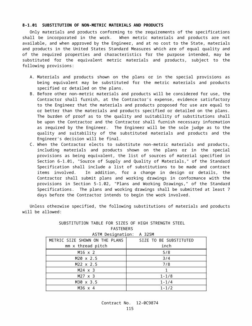
REMOVE ASPHALT CONCRETE OVERSIDE DRAINExisting asphalt concrete overside drain, where shown on the plans to be removed, shall be removed.Prior to removing the overside drain, the outside edge of the asphalt concrete to remain in place shall be cut on a neat
line to a minimum depth of 50 mm.The overside drain shall be removed in such a manner that the surfacing which is to remain in place is not damaged.The overside drain shall be disposed of outside the highway right of way in conformance with the provisions in Section
7-1.13 of the Standard Specifications.
ADJUST MANHOLE TO GRADEExisting manholes shall be adjusted to grade in conformance with the provisions in Section 15-2.05, "Reconstruction," of
the Standard Specifications.
REMOVE CONCRETE (CURB, GUTTER, AND SIDEWALK)Concrete curb, gutter, and sidewalk, where shown on the plans to be removed, shall be removed.Removing concrete curb and gutter, , and concrete sidewalk will be measured by the square meter, measured before and
during removal operations.Concrete removed shall be disposed of outside the highway right of way in conformance with the provisions in Section
7-1.13, "Disposal of Material Outside the Highway Right of Way," of the Standard Specifications.
10-1.21 CLEARING AND GRUBBINGClearing and grubbing shall conform to the provisions in Section 16, "Clearing and Grubbing," of the Standard
Specifications and these special provisions.Vegetation shall be cleared and grubbed only within the excavation and embankment slope lines.Existing vegetation outside the areas to be cleared and grubbed shall be protected from injury or damage resulting from
the Contractor's operations.Activities controlled by the Contractor, except cleanup or other required work, shall be confined within the graded areas
of the roadway.Nothing herein shall be construed as relieving the Contractor of the Contractor's responsibility for final cleanup of the
highway as provided in Section 4-1.02, "Final Cleaning Up," of the Standard Specifications.
10-1.22 EARTHWORKEarthwork shall conform to the provisions in Section 19, "Earthwork," of the Standard Specifications and these special
provisions.Backfill for drainage basin slopes shall be compacted to a relative compaction of not less than 95%.Surplus excavated material shall become the property of the Contractor and shall be disposed of in conformance with the
provisions in Section 7-1.13, "Disposal of Material Outside the Highway Right of Way," of the Standard Specifications.Where a portion of the existing surfacing is to be removed, the outline of the area to be removed shall be cut on a neat
line with a power-driven saw to a minimum depth of 50 mm before removing the surfacing. Full compensation for cutting the existing surfacing shall be considered as included in the contract price paid per cubic meter for roadway excavation and no additional compensation will be allowed therefor.
Reinforced concrete rubble shall not be used.
10-1.23 QUALITY CONTROL SEED TESTINGIn accordance with Section 6-3.02, "Testing by Contractor," of the Standard Specifications, seed that is required for
Erosion Control (Type D) shall be tested by the Contractor to ensure quality control of purity, germination, and pure live seed content of seed. The percent of seed germination shall include the germination percentage of hard and dormant seed.
The Contractor shall procure a seed laboratory certified by the Association of Official Seed Analysts for seed testing. Seed sampling shall be in accordance with the seed laboratory's specifications. Seed to be tested shall be sent to the laboratory within 5 working days upon receipt of seed by the Contractor from the vendor. The Contractor shall furnish one copy of the test results to the Engineer within 5 working days of receiving the test results. The test results shall include the name and address and contact person of the seed laboratory that performed the tests.
Contract No. 12-0C9874117
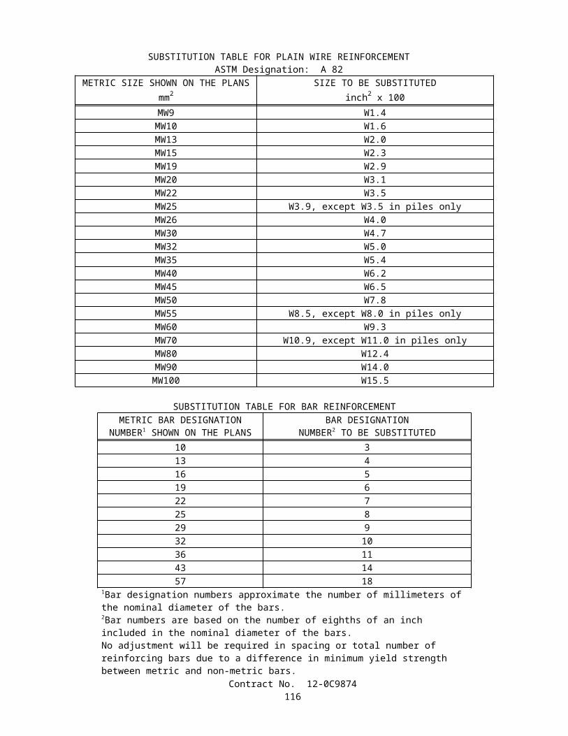
10-1.24 MOVE-IN/MOVE-OUT (EROSION CONTROL) Move-in/move-out (erosion control) shall include moving onto the project when an area is ready to receive erosion
control as determined by the Engineer, setting up all required personnel and equipment for the application of erosion control materials and moving out all personnel and equipment when erosion control in that area is completed.
When areas are ready to receive applications of erosion control (Type D), as determined by the Engineer, the Contractor shall begin erosion control work in that area within 5 working days of the Engineer’s notification to perform the erosion control work.
Attention is directed to the requirements of erosion control (Type D) elsewhere in these special provisions.Quantities of move-in/move-out (erosion control) will be determined as units from actual count as determined by the
Engineer. For measurement purposes, a move-in followed by a move-out will be considered as one unit.The contract unit price paid for move-in/move-out (erosion control) shall include full compensation for furnishing all
labor, materials (excluding erosion control materials), tools, equipment, and incidentals and for doing all the work involved in moving in and removing from the project all personnel and equipment necessary for application of erosion control (Type D), as shown on the plans, as specified in the Standard Specifications and these special provisions, and as directed by the Engineer.
No adjustment of compensation will be made for any increase or decrease in the quantities of move-in/move-out (erosion control) required, regardless of the reason for the increase or decrease. The provisions in Section 4-1.03B, "Increased or Decreased Quantities," of the Standard Specifications shall not apply to the item of move-in/move-out (erosion control).
10-1.25 EROSION CONTROL (TYPE D)Erosion control (Type D) shall conform to the provisions in Section 20-3, "Erosion Control," of the Standard
Specifications and these special provisions and shall consist of applying erosion control materials to embankment and excavation slopes and other areas disturbed by construction activities.
Erosion control (Type D) shall be applied when an area is ready to receive erosion control as determined by the Engineer and in conformance with the provisions in "Move-in/Move-out (Erosion Control)" of these special provisions.
Prior to installing erosion control materials, soil surface preparation shall conform to the provisions in Section 19-2.05, "Slopes," of the Standard Specifications, except that rills and gullies exceeding 50 mm in depth or width shall be leveled. Vegetative growth, temporary erosion control materials, and other debris shall be removed from areas to receive erosion control.
All surfaces receiving erosion control (Type D) shall be loosened by raking immediately prior to placement.
MATERIALSMaterials shall conform to the provisions in Section 20-2, "Materials," of the Standard Specifications and these special
provisions.
SeedSeed shall conform to the provisions in Section 20-2.10, "Seed," of the Standard Specifications. Individual seed species
shall be measured and mixed in the presence of the Engineer.Seed shall be delivered to the project site in unopened separate containers with the seed tag attached. Containers without
a seed tag attached will not be accepted.A sample of approximately 30 g of seed will be taken from each seed container by the Engineer.
Non-Legume SeedNon-legume seed shall consist of the following:
Contract No. 12-0C9874118
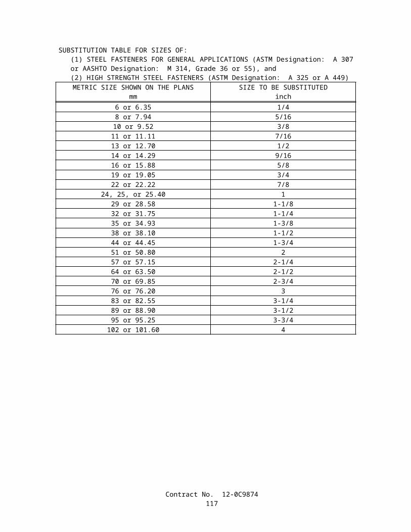
NON-LEGUME SEEDBotanical Name
(Common Name)Percent Germination
(Minimum) Kilograms Pure Live Seed Per Hectare
(Slope Measurement)Agrostis pallens(Thingrass)
40 4
Eschscholzia californica(California Poppy)
45 1.5
Nassella lepida(Foothill Needlegrass)
35 3
Nassella pulchra(Purple Needlegrass)
35 2
Vulpia microstachys(Small Fescue)
40 4
StrawStraw shall conform to the provisions in Section 20-2.06, "Straw," of the Standard Specifications and these special
provisions.Straw shall be derived from rice.Straw shall be free of plastic, glass, metal, rocks, and refuse or other deleterious material.
CompostCompost shall be Class A, exceptional quality biosolids composts, conforming to the requirements in United States
Environmental Protection Agency (EPA) regulation 40 CFR, Part 503c.Compost shall not contain paint, petroleum products, herbicides, fungicides or other chemical residues harmful to plant
or animal life. Other deleterious material, plastic, glass, metal or rock shall not exceed 0.1-percent by weight or volume.Compost shall be thermophilically processed for 15 days. During this process, the compost shall be maintained at
minimum internal temperature of 55˚C and be thoroughly turned at least 5 times. A 90-day curing period shall follow the thermophilic process.
Compost shall be screened through a screen no larger than 12 mm.Compost shall measure at least 6 on the maturity and stability scale with a Solvita test kit.A Certificate of Compliance for compost shall be furnished to the Engineer in conformance with the provisions in
Section 6-1.07, "Certificates of Compliance," of the Standard Specifications. The Certificate of Compliance shall state the Solvita maturity and stability scale test result of the compost.
Stabilizing EmulsionStabilizing emulsion shall conform to the provisions in Section 20-2.11, "Stabilizing Emulsion," of the Standard
Specifications and these special provisions.Stabilizing emulsion shall be in a dry powder form, may be reemulsifiable, and shall be a processed organic adhesive
used as a soil tackifier.
APPLICATIONErosion control materials shall be applied in separate applications in the following sequence:A. The following mixture in the rates indicated shall be applied with hydro-seeding equipment within 60 minutes after
the seed has been added to the mixture:
Material Kilograms Per Hectare(Slope Measurement)
Non-Legume Seed 14.5Fiber 350
Material Cubic Meter Per Hectare
(Slope Measurement)Compost 120
Contract No. 12-0C9874119
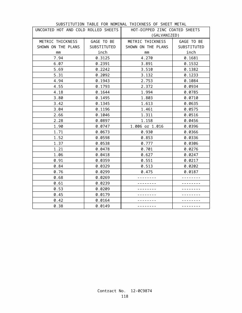
B. The Contractor may dry apply compost at the total of the rates specified in the preceding table and the following table instead of including it as part of the hydro-seeding operations. In areas where the compost is dry applied, all compost for that area shall be applied before the next operation.
C. Straw shall be applied at the rate of 4.0 tonnes per hectare based on slope measurements. Incorporation of straw will not be required. Straw shall be distributed evenly without clumping or piling. Straw shall be applied within 24 hours after seed has been applied.
D. The following mixture in the rates indicated shall be applied with hydro-seeding equipment:
Material Kilograms Per Hectare(Slope Measurement)
Fiber 510Stabilizing Emulsion (Solids) 140
Material Cubic Meter Per Hectare
(Slope Measurement)Compost 87
The ratio of total water to total stabilizing emulsion in the mixture shall be as recommended by the manufacturer.Once straw work is started in an area, stabilizing emulsion applications shall be completed in that area on the same
working day.The rates of erosion control materials may be changed by the Engineer to meet field conditions.
MEASUREMENT AND PAYMENTCompost (erosion control) will be measured by the cubic meter in the vehicle at the point of delivery in conformance
with the provisions in Section 9-1.01, "Measurement of Quantities," of the Standard Specifications.The contract price paid per cubic meter for compost (erosion control) shall include full compensation for furnishing all
labor, materials, tools, equipment, and incidentals, and for doing all the work involved in applying compost for erosion control, complete in place, as shown on the plans, as specified in the Standard Specifications and these special provisions, and as directed by the Engineer.
10-1.26 AGGREGATE SUBBASEAggregate subbase shall be Class 2 and shall conform to the provisions in Section 25, "Aggregate Subbases," of the
Standard Specifications and these special provisions.The restriction that the amount of reclaimed material included in Class 1, Class 2 and Class 3 aggregate subbase not
exceed 50 percent of the total volume of the aggregate used shall not apply. Aggregate for Class 1, Class 2 and Class 3 aggregate subbase may include reclaimed glass. Aggregate subbase incorporating reclaimed glass shall not be placed at locations where material will not be placed over the aggregate subbase.
10-1.27 AGGREGATE BASEAggregate base shall be Class 2 and shall conform to the provisions in Section 26, "Aggregate Bases," of the Standard
Specifications and these special provisions.The restriction that the amount of reclaimed material included in Class 2 aggregate base not exceed 50 percent of the
total volume of the aggregate used shall not apply. Aggregate for Class 2 aggregate base may include reclaimed glass. Aggregate base incorporating reclaimed glass shall not be placed at locations where surfacing will not be placed over the aggregate base.
10-1.28 LEAN CONCRETE BASELean concrete base shall conform to the provisions in Section 28, "Lean Concrete Base," of the Standard Specifications.
10-1.29 ASPHALT CONCRETEThis work shall consist of furnishing and placing asphalt concrete in conformance with these special provisions.Asphalt concrete shall be produced at an established commercial mixing plant. The aggregate and asphalt binder shall be
heated and mixed thoroughly.At the option of the Contractor, the maximum size aggregate shall be either 12.5-mm or 9.5-mm.Prior to spreading asphalt concrete, a paint binder of asphaltic emulsion or of paving asphalt shall be furnished and
applied uniformly to the pavement to be surfaced and to contact surfaces of cold pavement joints, curbs, gutters and to other Contract No. 12-0C9874
120
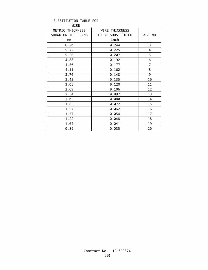
surfaces designated by the Engineer. If paving asphalt is furnished, the paving asphalt shall be applied at a temperature of not less than 140°C or more than 175°C.
Asphalt concrete shall be spread and compacted by methods that will produce an asphalt concrete surfacing true to grade and cross section, of uniform smoothness and texture, compacted firmly and free from depressions, humps or irregularities.
Asphalt concrete to be placed in areas designated on the plans as miscellaneous areas may be spread in one layer to the required line, grade, and cross section and shall be compacted firmly.
Dikes shall be shaped and compacted with equipment that shapes and compacts the material to the required cross section.Compensation for the work performed under this section "Asphalt Concrete," including the asphalt concrete, dikes,
surfacing miscellaneous areas, and paint binder, shall conform to the provisions in Section 39-8.01, "Measurement," and Section 39-8.02, "Payment," of the Standard Specifications.
Full compensation for furnishing and applying a fog seal coat of asphaltic emulsion shall be considered as included in the contract price paid per tonne for asphalt concrete and no separate payment will be made therefor.
10-1.30 CONCRETE STRUCTURESPortland cement concrete structures shall conform to the provisions in Section 51, "Concrete Structures," of the Standard
Specifications.
10-1.31 REINFORCEMENTReinforcement shall conform to the provisions in Section 52, "Reinforcement," of the Standard Specifications and these
special provisions.The Department's mechanical splices prequalified list can be found at the following internet site:
http://www.dot.ca.gov/hq/esc/approved_products_list/
The provisions of "Welding Quality Control" of these special provisions shall not apply to resistance butt welding.
10-1.32 ALTERNATIVE PIPEAlternative pipe culverts shall conform to the provisions in Section 62, "Alternative Culverts," of the Standard
Specifications.
10-1.33 PLASTIC PIPEPlastic pipe shall conform to the provisions in Section 64, "Plastic Pipe," of the Standard Specifications.
10-1.34 REINFORCED CONCRETE PIPEReinforced concrete pipe shall conform to the provisions in Section 65, "Reinforced Concrete Pipe," of the Standard
Specifications and these special provisions.Where embankment will not be placed over the top of the pipe, a relative compaction of not less than 85 percent shall be
required below the pipe spring line for pipe installed using Method 1 backfill in trench, as shown on Standard Plan A62D. Where the pipe is to be placed under the traveled way, a relative compaction of not less than 90 percent shall be required unless the minimum distance between the top of the pipe and the pavement surface is the greater of 1.2 m or one half of the outside diameter of the pipe.
Except as otherwise designated by classification on the plans or in the specifications, joints for culvert and drainage pipes shall conform to the plans or specifications for standard joints.
When reinforced concrete pipe is installed in conformance with the details shown on Revised Standard Plan A62DA, the fifth paragraph of Section 19-3.04, "Water Control and Foundation Treatment," of the Standard Specifications shall not apply.
When solid rock or other unyielding material is encountered at the planned elevation of the bottom of the bedding, the material below the bottom of the bedding shall be removed to a depth of 1/50 of the height of the embankment over the top of the culvert, but not less than 150 mm nor more than 300 mm. The resulting trench below the bottom of the bedding shall be backfilled with structure backfill material in conformance with the provisions in Section 19-3.06, "Structure Backfill," of the Standard Specifications.
The excavation and backfill below the planned elevation of the bottom of the bedding will be paid for as extra work as provided in Section 4-1.03D, "Extra Work," of the Standard Specifications.
The Outer Bedding shown on Revised Standard Plan A62DA shall not be compacted prior to placement of the pipe.
Contract No. 12-0C9874121
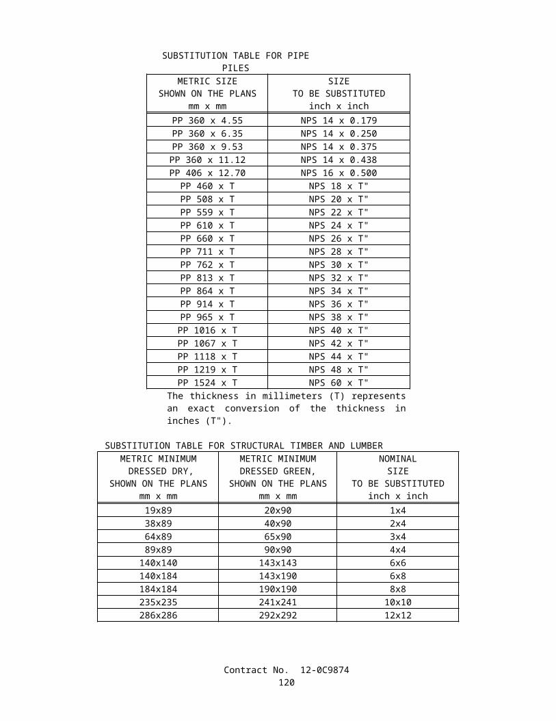
10-1.35 MISCELLANEOUS FACILITIESCorrugated steel pipe riser, debris rack cage, and precast concrete pipe manhole shall conform to the provisions in
Section 70, "Miscellaneous Facilities," of the Standard Specifications and these special provisions.The corrugated metal pipe riser, wire mesh support frame, ladder, and debris rack cage shall be galvanized. All orifice
edges shall be galvanized. Galvanizing shall conform to the provisions in Section 75-1.05, “Galvanizing,” of the Standard Specifications. All metals shall be galvanized at fabrication shop before delivery to job site.
The contract price paid per meter for corrugated metal pipe riser shall include full compensation for furnishing all labor, materials, tools, equipment, and incidentals, and for doing all the work involved in constructing the corrugated metal pipe riser, complete in place, including vertical riser pipe, horizontal section of corrugated metal pipe, structure excavation, structure backfill, and ladder as shown on the plans, as specified by in the Standard Specifications and these special provisions, and as directed by the Engineer.
10-1.36 MISCELLANEOUS CONCRETE CONSTRUCTIONCurb, sidewalk driveway and basin ramp shall conform to the provisions in Section 73, "Concrete Curbs and Sidewalks,"
of the Standard Specifications and these special provisions.The concrete for basin ramps shall contain not less than 350 kg of portland cement per cubic meter.
10-1.37 MISCELLANEOUS IRON AND STEELMiscellaneous iron and steel shall conform to the provisions in Section 75, "Miscellaneous Metal," of the Standard
Specifications.
10-1.38 STAINLESS STEEL WIRE MESHStainless steel wire mesh shall be constructed to the size and dimensions shown on the plans and shall conform to these
special provisions.Stainless steel wire mesh shall be fabricated with Type 304 stainless steel conforming to the requirements in ASTM
Designation: E2016-99.The contract price paid per square meter for stainless steel wire mesh shall include full compensation for furnishing all
labor, materials, tools, equipment, and incidentals, and for doing all the work involved in constructing the stainless steel wire mesh, complete in place, including tying to the wire mesh support frame as shown on the plans, as specified by in the Standard Specifications and these special provisions, and as directed by the Engineer.
SECTION 10-2 HIGHWAY PLANTING AND IRRIGATION SYSTEMS
10-2.01 GENERALThe work performed in connection with highway planting and irrigation systems shall conform to the provisions in
Section 20, "Erosion Control and Highway Planting," of the Standard Specifications and these special provisions.The Contractor shall notify the Engineer not less than 72 hours prior to requiring initial access to the existing irrigation
controllers. When the Engineer determines that access to the controllers is required at other times, arrangements will be made to provide this access.
COST BREAK-DOWNThe Contractor shall furnish the Engineer a cost break-down for the contract lump sum item of irrigation system. The
cost break-down table shall be submitted to the Engineer for approval within 15 working days after the contract has been approved. The cost break-down table shall be approved, in writing, by the Engineer before any partial payment will be made for the item of irrigation system.
The cost break-down shall be completed and furnished in the format shown in the sample of the cost break-down included in this section. Line item descriptions of work shown in the samples are the minimum to be submitted. Additional line item descriptions of work may be designated by the Contractor. If the Contractor elects to designate additional line item descriptions of work, the quantity, value and amount for those line items shall be completed in the same manner as for the line item descriptions shown in the samples. The line items and quantities given in the sample are to show the manner of preparing the cost break-down to be furnished by the Contractor.
The Contractor shall determine the quantities required to complete the work shown on the plans. The quantities and their values shall be included in the cost break-down submitted to the Engineer for approval. The Contractor shall be responsible for the accuracy of the quantities and values used in the cost break-down submitted for approval.
Contract No. 12-0C9874122
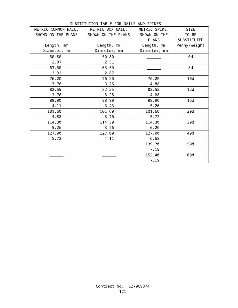
The sum of the amounts for the line items of work listed in the cost break-down table for irrigation system work shall be equal to the contract lump sum price bid for the work. Overhead and profitshall be included in each individual line item of work listed in the cost break-down table.
No adjustment in compensation will be made in the contract lump sum price paid for irrigation system due to differences between the quantities shown in the cost break-down table furnished by the Contractor and the quantities required to complete the work as shown on the plans and as specified in these special provisions.
Individual line item values in the approved cost break-down table will be used to determine partial payments during the progress of the work and as the basis for calculating an adjustment in compensation for the contract lump sum item of irrigation system due to changes in line items of work ordered by the Engineer. When the total value of ordered changes to line items of work increases or decreases the lump sum price bid for irrigation system by more than 25 percent, the adjustment in compensation will be determined in the same manner specified for increases and decreases in the total pay quantity of an item of work in Section 4-1.03B, "Increased or Decreased Quantities," of the Standard Specifications.
Contract No. 12-0C9874123

IRRIGATION SYSTEM COST BREAK-DOWN
Contract No. 12-0C9874
UNIT DESCRIPTION UNITAPPROXIMATE
QUANTITY VALUE AMOUNT50 mm Plastic Pipe (PR 200) (Supply Line) M 80
40 mm Plastic Pipe (PR 200) (Supply Line) M 15
32 mm Plastic Pipe (PR 200) (Supply Line) M 45
25 mm Plastic Pipe (PR 200) (Supply Line) M 75
20 mm Plastic Pipe (PR 200) (Supply Line) M 135
Sprinkler (Type A-1) EA 8
Sprinkler (Type B-5) EA 6
Check and Test Existing Irrigation Facilities LS Lump Sum
Remove Existing Irrigation Facilities LS Lump Sum
Control and Neutral Conductors LS Lump Sum
Install Reclaimed Water Warning Signs LS Lump Sum
Furnishing and Installing Permanently Affixed Purple Striping Tape on Reclaimed Water Supply Lines
LS Lump Sum
Final Irrigation System Check LS Lump Sum
TOTAL ____________________
Contract No. 12-0C9874124
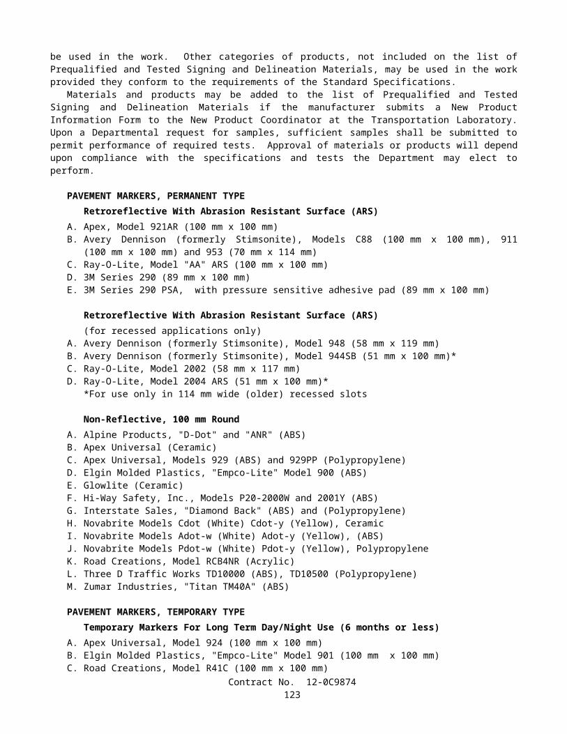
10-2.02 EXISTING HIGHWAY PLANTINGIn addition to the provisions in Section 20, "Erosion Control and Highway Planting," of the Standard Specifications,
work performed in connection with existing highway planting shall conform to the provisions in "Existing Highway Facilities," of these special provisions.
Replacement planting shall conform to the provisions in "Preservation of Property" of these special provisions.
MAINTAIN EXISTING PLANTED AREASExisting planted areas shall be maintained as directed by the Engineer. Maintaining existing planted areas will be paid
for as extra work as provided in Section 4-1.03D, "Extra Work," of the Standard Specifications.Attention is directed to "Preservation of Property" of these special provisions.
10-2.03 EXISTING HIGHWAY IRRIGATION FACILITIESThe work performed in connection with the various existing highway irrigation system facilities shall conform to the
provisions in "Existing Highway Facilities," of these special provisions.Water shall be maintained in conformance with the provisions in Section 20-5.025, "Maintain Existing Water Supply,"
of the Standard Specifications.
CHECK AND TEST EXISTING IRRIGATION FACILITIESExisting irrigation facilities that are to remain or to be relocated, and that are within those areas where clearing and
grubbing or earthwork operations are to be performed, shall be checked for missing or damaged components and proper operation prior to performing clearing and grubbing or earthwork operations. Existing irrigation facilities outside of work areas that are affected by the construction work shall also be checked for proper operation.
A written list of existing irrigation system deficiencies shall be submitted to the Engineer within 5 working days after checking the existing facilities.
Deficiencies found during checking of the existing facilities shall be corrected as directed by the Engineer. Corrective work ordered by the Engineer will be paid for as extra work as provided in Section 4-1.03D, "Extra Work," of the Standard Specifications.
Length of watering cycles for use of non-potable water from water meters for checking or testing existing irrigation facilities shall be as determined by the Engineer.
Additional repairs required for the existing irrigation system as ordered by the Engineer, except as otherwise provided for in "Maintain Existing Irrigation Facilities" of these special provisions, will be paid for as extra work as provided in Section 4-1.03D, "Extra Work," of the Standard Specifications.
MAINTAIN EXISTING IRRIGATION FACILITIESExisting irrigation facilities shall be maintained throughout the life of the contract. Prior to the start of maintaining
existing irrigation facilities work, the facilities shall be checked for proper operation, and repaired in conformance with the provisions in "Check and Test Existing Irrigation Facilities" of these special provisions.
After the existing facilities have been checked and repaired, the Contractor shall be responsible for the routine maintenance of existing irrigation systems. The work shall include, but not limited to, checking irrigation systems for proper operation and adjusting, repairing or replacing valves, valve boxes, sprinklers, risers, swing joints, wye strainers, valve assembly units, and filter assembly units.
The Contractor will not be responsible for maintaining existing water meters, underground pipe supply lines, control and neutral conductors, and electrical conduits. Except as otherwise specified in "Existing Highway Irrigation Facilities" of these special provisions, repair work to these facilities ordered by the Engineer will be paid for as extra work as provided in Section 4-l.03D, "Extra Work," of the Standard Specifications.
Existing automatic irrigation systems shall be operated automatically during the life of the contract, except manual operation will be allowed for the work during the repair of irrigation facilities.
Irrigation controllers shall be programmed by the Contractor for seasonal water requirements. During winter seasons irrigation systems shall be operated automatically a minimum of 2 minutes every 2 weeks.
Irrigation systems and facilities shall be checked for proper operation at least once every 30 days. When required, as determined by the Engineer, adjusting, repairing or replacing irrigation facilities shall be completed within 5 working days after checking the irrigation systems. Except as provided in these special provisions, repair and replacement of irrigation facilities shall conform to the provisions in "Existing Highway Irrigation Facilities" of these special provisions.
Except as provided in these special provisions, the contract lump sum price paid for maintain existing irrigation facilities shall include full compensation for furnishing all labor, materials, tools, equipment, and incidentals, and for doing all the
Contract No. 12-0C9874125
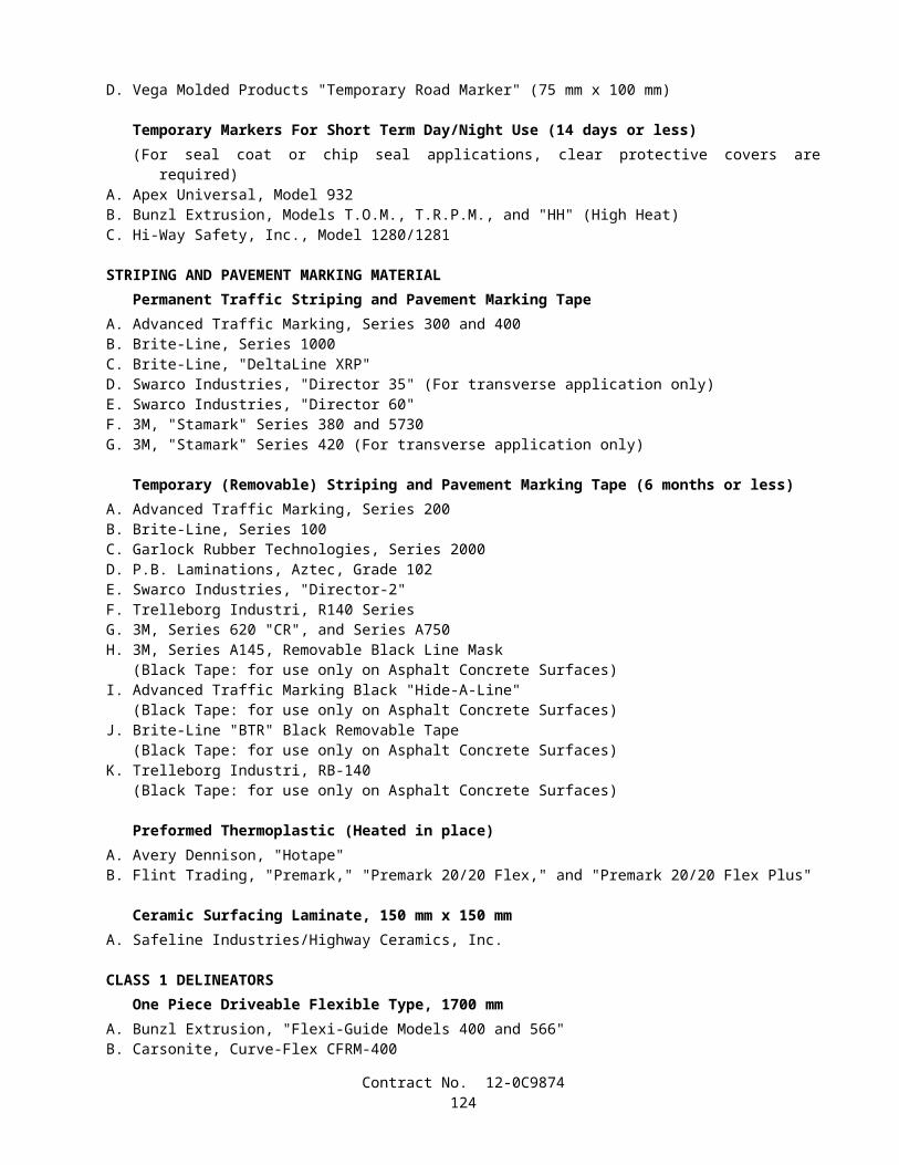
work involved in maintaining existing irrigation facilities, complete in place, including checking irrigation facilities, as shown on the plans, as specified in the Standard Specifications and these special provisions, and as directed by the Engineer.
REMOVE EXISTING IRRIGATION FACILITIESExisting irrigation facilities where shown on the plans to be removed, shall be removed. Facilities that are more than
150 mm below finished grade may be abandoned in place.Immediately after disconnecting an existing irrigation facility to be removed or abandoned from an existing facility to
remain, the remaining facility shall be capped or plugged, or shall be connected to a new or existing irrigation facility.Facilities to be removed shall be disposed of in conformance with the provisions in Section 7-1.13, "Disposal of Material
Outside the Highway Right of Way," of the Standard Specifications.
10-2.04 (BLANK)
10-2.05 IRRIGATION SYSTEMSIrrigation systems shall be furnished and installed in conformance with the provisions in Section 20-5, "Irrigation
Systems," of the Standard Specifications, except materials containing asbestos fibers shall not be used.Attention is directed to the provisions in "Obstructions" of these special provisions, regarding work over or adjacent to
existing underground facilities. Excavation for proposed irrigation facilities shall not be started until the existing underground facilities have been located.
Method A pressure testing shall conform to the provisions in Section 20-5.03H(1), "Method A", of the Standard Specifications, except leaks that develop in the tested portion of the system shall be located and repaired after each test period when a drop of more than 35 kPa is indicated by the pressure gage. After the leaks have been repaired, the one hour pressure test shall be repeated and additional repairs made until the drop in pressure is 35 kPa or less.
PIPEPlastic Pipe
Plastic pipe supply lines shall be polyvinyl chloride (PVC) 1120 or 1220 pressure rated pipe with the minimum pressure rating (PR) of 200.
Plastic pipe supply lines less than 100 mm in diameter shall have solvent cemented type joints. Primers shall be used on the solvent cemented type joints.
Reclaimed Water Supply LinesNew and exposed reclaimed water supply lines shall be marked with a permanently affixed purple warning tape bearing
the continuous wording "CAUTION RECLAIMED WATER." The tape shall be wrapped around the supply lines in a manner that produces a uniform and smooth fit, free of irregularities.
At the Contractor's option, purple colored polyvinyl chloride (PVC) supply lines may be used for reclaimed water supply lines in place of standard PVC supply line with affixed purple warning tape. Purple colored PVC supply lines shall conform to the following:
A. Pipe shall be made of PVC 1120 with the minimum pressure ratings (PR) shown on the plans.B. Pipe shall conform to the requirements in one of the following Standards: ASTM Designation: D 1785, ASTM
Designation: D 3139 and ASTM Designation: D 2241 or ASTM Designation: D 2672.C. Pipe shall have permanent wording "CAUTION RECLAIMED WATER" in 2 rows, approximately 180 degrees
apart, in the longitudinal direction of the pipe. The warning message shall be repeated every 600 mm continuously along the pipe.
Full compensation for furnishing and installing permanently affixed purple striping tape on reclaimed water supply lines shall be considered as included in the contract lump sum price paid for irrigation system and no additional compensationwill be allowed therefor.
SPRINKLERSSprinklers shall conform to the type, pattern, material, and operating characteristics listed in the "Sprinkler Schedule"
shown on the plans.
Contract No. 12-0C9874126

RECLAIMED WATER WARNING SIGNReclaimed water warning signs shall be affixed to the above ground irrigation facilities that use or are associated with
reclaimed water. Reclaimed water warning signs and aluminum sign plates for warning signs will be State-furnished as provided under "State-furnished Materials" of these special provisions.
Warning signs will be flexible self-adhesive decals with peel-off backs. Decals shall be applied directly to irrigation facilities with smooth surfaces or affixed to 1.6 mm thick aluminum sign plates which shall be attached to the various above ground irrigation facilities.
Warning signs on above ground irrigation facilities shall be placed in visible locations.Self-adhesive warning signs shall be applied directly to clean smooth surfaces. The smooth surfaces shall be cleaned
with alcohol, or an equivalent cleaner, before applying the decals.Reclaimed water warning decals or decals on aluminum sign plates shall be permanently affixed to nozzle lines,
sprinkler risers, and other irrigation facilities in conformance with the details shown on the plans.The 50 mm x 50 mm self-adhesive decals shall be permanently affixed to sprinkler risers.Marking underground pipe for reclaimed water shall conform to the provisions in "Pipe" of these special provisions.Full compensation for install reclaimed water warning sign shall be considered as included in the contract lump sum
price paid for irrigation system and no separate payment will be made therefor.
FINAL IRRIGATION SYSTEM CHECKA final check of existing and new irrigation facilities shall be performed not more than 20 working days prior to
acceptance of the contract.The length of watering cycles using non-potable water measured by water meters for the final check of irrigation
facilities will be determined by the Engineer.Remote control valves connected to existing irrigation controllers shall be checked for automatic performance when the
controllers are in automatic mode.Unsatisfactory performance of irrigation facilities installed or modified by the Contractor shall be repaired and rechecked
at the Contractor's expense until satisfactory performance is obtained, as determined by the Engineer.Repair or replacement of existing irrigation facilities due to unsatisfactory performance shall conform to the provisions
in "Existing Highway Irrigation Facilities" of these special provisions.Nothing in this section "Final Irrigation System Check" shall relieve the Contractor of full responsibility for making
good or repairing defective work or materials found before the formal written acceptance of the entire contract by the Director.
Full compensation for checking the irrigation systems prior to the acceptance of the contract shall be considered as included in the contract lump sum price paid for irrigation system and no additional compensation will be allowed therefor.
SECTION 11. (BLANK)
SECTION 12. (BLANK)
SECTION 13. (BLANK)
Contract No. 12-0C9874127

SECTION 14 FEDERAL REQUIREMENTS FOR FEDERAL-AID CONSTRUCTION PROJECTS
GENERAL.—The work herein proposed will be financed in whole or in part with Federal funds, and therefore all of the statutes, rules and regulations promulgated by the Federal Government and applicable to work financed in whole or in part with Federal funds will apply to such work. The "Required Contract Provisions, Federal-Aid Construction Contracts, "Form FHWA 1273, are included in this Section 14. Whenever in said required contract provisions references are made to "SHA contracting officer," "SHA resident engineer," or "authorized representative of the SHA," such references shall be construed to mean "Engineer" as defined in Section 1-1.18 of the Standard Specifications.
PERFORMANCE OF PREVIOUS CONTRACT.—In addition to the provisions in Section II, "Nondiscrimination," and Section VII, "Subletting or Assigning the Contract," of the required contract provisions, the Contractor shall comply with the following:
The bidder shall execute the CERTIFICATION WITH REGARD TO THE PERFORMANCE OF PREVIOUS CONTRACTS OR SUBCONTRACTS SUBJECT TO THE EQUAL OPPORTUNITY CLAUSE AND THE FILING OF REQUIRED REPORTS located in the proposal. No request for subletting or assigning any portion of the contract in excess of $10,000 will be considered under the provisions of Section VII of the required contract provisions unless such request is accompanied by the CERTIFICATION referred to above, executed by the proposed subcontractor.
NON-COLLUSION PROVISION.—The provisions in this section are applicable to all contracts except contracts for Federal Aid Secondary projects.
Title 23, United States Code, Section 112, requires as a condition precedent to approval by the Federal Highway Administrator of the contract for this work that each bidder file a sworn statement executed by, or on behalf of, the person, firm, association, or corporation to whom such contract is to be awarded, certifying that such person, firm, association, or corporation has not, either directly or indirectly, entered into any agreement, participated in any collusion, or otherwise taken any action in restraint of free competitive bidding in connection with the submitted bid. A form to make the non-collusion affidavit statement required by Section 112 as a certification under penalty of perjury rather than as a sworn statement as permitted by 28, USC, Sec. 1746, is included in the proposal.
PARTICIPATION BY MINORITY BUSINESS ENTERPRISES IN SUBCONTRACTING.—Part 23, Title 49, Code of Federal Regulations applies to this Federal-aid project. Pertinent sections of said Code are incorporated in part or in its entirety within other sections of these special provisions.
Schedule B—Information for Determining Joint Venture Eligibility
(This form need not be filled in if all joint venture firms are minority owned.)
1. Name of joint venture __________________________________________________________________________2. Address of joint venture ________________________________________________________________________3. Phone number of joint venture ___________________________________________________________________4. Identify the firms which comprise the joint venture. (The MBE partner must complete Schedule A.) ___________
____________________________________________________________________________________________
a. Describe the role of the MBE firm in the joint venture. _____________________________________________________________________________________________________________________________________
b. Describe very briefly the experience and business qualifications of each non-MBE joint venturer: ____________________________________________________________________________________________________
5. Nature of the joint venture's business ___________________________________________________________________________________________________________________________________________________________
6. Provide a copy of the joint venture agreement.7. What is the claimed percentage of MBE ownership? __________________________________________________8. Ownership of joint venture: (This need not be filled in if described in the joint venture agreement, provided by
question 6.).
a. Profit and loss sharing.b. Capital contributions, including equipment.c. Other applicable ownership interests.
Contract No. 12-0C9874128
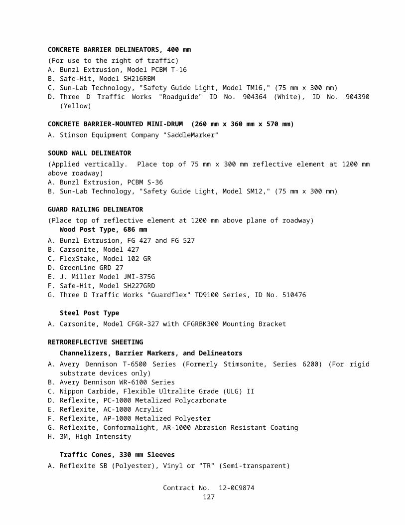
9. Control of and participation in this contract. Identify by name, race, sex, and "firm" those individuals (and their titles) who are responsible for day-to-day management and policy decision making, including, but not limited to, those with prime responsibility for:
a. Financial decisions ________________________________________________________________________b. Management decisions, such as:
(1) Estimating ___________________________________________________________________________(2) Marketing and sales ____________________________________________________________________(3) Hiring and firing of management personnel _________________________________________________
_____________________________________________________________________________________(4) Purchasing of major items or supplies ______________________________________________________
_____________________________________________________________________________________
c. Supervision of field operations _______________________________________________________________
Note.—If, after filing this Schedule B and before the completion of the joint venture's work on the contract covered by this regulation, there is any significant change in the information submitted, the joint venture must inform the grantee, either directly or through the prime contractor if the joint venture is a subcontractor.
Affidavit"The undersigned swear that the foregoing statements are correct and include all material information necessary to
identify and explain the terms and operation of our joint venture and the intended participation by each joint venturer in the undertaking. Further, the undersigned covenant and agree to provide to grantee current, complete and accurate information regarding actual joint venture work and the payment therefor and any proposed changes in any of the joint venture arrangements and to permit the audit and examination of the books, records and files of the joint venture, or those of each joint venturer relevant to the joint venture, by authorized representatives of the grantee or the Federal funding agency. Any material misrepresentation will be grounds for terminating any contract which may be awarded and for initiating action under Federal or State laws concerning false statements."
____________________________________________________________________________Name of Firm Name of Firm
____________________________________________________________________________Signature Signature
____________________________________________________________________________Name Name
____________________________________________________________________________Title Title
____________________________________________________________________________Date Date
Contract No. 12-0C9874129
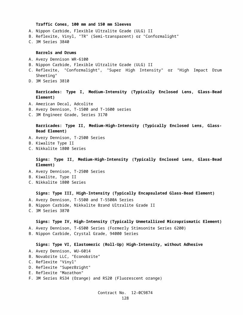
Date _______________________________________________
State of ____________________________________________
County of __________________________________________
On this ____ day of _______________, 20___, before me appeared (Name) _________________, to me personally known, who, being duly sworn, did execute the foregoing affidavit, and did state that he or she was properly authorized by (Name of firm) ________________________________ to execute the affidavit and did so as his or her free act and deed.
Notary Public __________________________________________
Commission expires _____________________________________
[Seal]
Date _______________________________________________
State of ____________________________________________
County of __________________________________________
On this ___ day of _______________, 20___, before me appeared (Name) _________________ to me personally known, who, being duly sworn, did execute the foregoing affidavit, and did state that he or she was properly authorized by (Name of firm) ___________________________ to execute the affidavit and did so as his or her free act and deed.
Notary Public __________________________________________
Commission expires _____________________________________
[Seal]
Contract No. 12-0C9874130
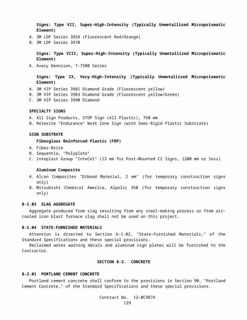
REQUIRED CONTRACT PROVISIONSFEDERAL-AID CONSTRUCTION CONTRACTS
I. GENERAL1. These contract provisions shall apply to all work performed on the contract by the contractor's own organization and
with the assistance of workers under the contractor's immediate superintendence and to all work performed on the contract by piecework, station work, or by subcontract.
2. Except as otherwise provided for in each section, the contractor shall insert in each subcontract all of the stipulations contained in these Required Contract Provisions, and further require their inclusion in any lower tier subcontract or purchase order that may in turn be made. The Required Contract Provisions shall not be incorporated by reference in any case. The prime contractor shall be responsible for compliance by any subcontractor or lower tier subcontractor with these Required Contract Provisions.
3. A breach of any of the stipulations contained in these Required Contract Provisions shall be sufficient grounds for termination of the contract.
4. A breach of the following clauses of the Required Contract Provisions may also be grounds for debarment as provided in 29 CFR 5.12:
Section I, paragraph 2;Section IV, paragraphs 1, 2, 3, 4, and 7;Section V, paragraphs 1 and 2a through 2g.
5. Disputes arising out of the labor standards provisions of Section IV (except paragraph 5) and Section V of these Required Contract Provisions shall not be subject to the general disputes clause of this contract. Such disputes shall be resolved in accordance with the procedures of the U.S. Department of Labor (DOL) as set forth in 29 CFR 5, 6, and 7. Disputes within the meaning of this clause include disputes between the contractor (or any of its subcontractors) and the contracting agency, the DOL, or the contractor's employees or their representatives.
6. Selection of Labor - During the performance of this contract, the contractor shall not:
a. discriminate against labor from any other State, possession, or territory of the United States (except for employment preference for Appalachian contracts, when applicable, as specified in Attachment A), or
b. employ convict labor for any purpose within the limits of the project unless it is labor performed by convicts who are on parole, supervised release, or probation.
II. NONDISCRIMINATION (Applicable to all Federal-aid construction contracts and to all related subcontracts of $10,000 or more.)
1. Equal Employment Opportunity: Equal employment opportunity (EEO) requirements not to discriminate and to take affirmative action to assure equal opportunity as set forth under laws, executive orders, rules, regulations (28 CFR 35, 29 CFR 1630, and 41 CFR 60) and orders of the Secretary of Labor as modified by the provisions prescribed herein, and imposed pursuant to 23 U.S.C. 140 shall constitute the EEO and specific affirmative action standards for the contractor's project activities under this contract. The Equal Opportunity Construction Contract Specifications set forth under 41 CFR 60-4.3 and the provisions of the American Disabilities Act of 1990 (42 U.S.C. 12101 et seq.) set forth under 28 CFR 35 and 29 CFR 1630 are incorporated by reference in this contract. In the execution of this contract, the contractor agrees to comply with the following minimum specific requirement activities of EEO:
a. The contractor will work with the State highway agency (SHA) and the Federal Government in carrying out EEO obligations and in their review of his/her activities under the contract.
b. The contractor will accept as his operating policy the following statement:
"It is the policy of this Company to assure that applicants are employed, and that employees are treated during employment, without regard to their race, religion, sex, color, national origin, age or disability. Such action
Contract No. 12-0C9874131

shall include: employment, upgrading, demotion, or transfer; recruitment or recruitment advertising; layoff or termination; rates of pay or other forms of compensation; and selection for training, including apprenticeship, preapprenticeship, and/or on-the-job training."
2. EEO Officer: The contractor will designate and make known to the SHA contracting officers an EEO Officer who will have the responsibility for and must be capable of effectively administering and promoting an active contractor program of EEO and who must be assigned adequate authority and responsibility to do so.
3. Dissemination of Policy: All members of the contractor's staff who are authorized to hire, supervise, promote, and discharge employees, or who recommend such action, or who are substantially involved in such action, will be made fully cognizant of, and will implement, the contractor's EEO policy and contractual responsibilities to provide EEO in each grade and classification of employment. To ensure that the above agreement will be met, the following actions will be taken as a minimum:
a. Periodic meetings of supervisory and personnel office employees will be conducted before the start of work and then not less often than once every six months, at which time the contractor's EEO policy and its implementation will be reviewed and explained. The meetings will be conducted by the EEO Officer.
b. All new supervisory or personnel office employees will be given a thorough indoctrination by the EEO Officer, covering all major aspects of the contractor's EEO obligations within thirty days following their reporting for duty with the contractor.
c. All personnel who are engaged in direct recruitment for the project will be instructed by the EEO Officer in the contractor's procedures for locating and hiring minority group employees.
d. Notices and posters setting forth the contractor's EEO policy will be placed in areas readily accessible to employees, applicants for employment and potential employees.
e. The contractor's EEO policy and the procedures to implement such policy will be brought to the attention of employees by means of meetings, employee handbooks, or other appropriate means.
4. Recruitment: When advertising for employees, the contractor will include in all advertisements for employees the notation: "An Equal Opportunity Employer." All such advertisements will be placed in publications having a large circulation among minority groups in the area from which the project work force would normally be derived.
a. The contractor will, unless precluded by a valid bargaining agreement, conduct systematic and direct recruitment through public and private employee referral sources likely to yield qualified minority group applicants. To meet this requirement, the contractor will identify sources of potential minority group employees, and establish with such identified sources procedures whereby minority group applicants may be referred to the contractor for employment consideration.
b. In the event the contractor has a valid bargaining agreement providing for exclusive hiring hall referrals, he is expected to observe the provisions of that agreement to the extent that the system permits the contractor's compliance with EEO contract provisions. (The DOL has held that where implementation of such agreements have the effect of discriminating against minorities or women, or obligates the contractor to do the same, such implementation violates Executive Order 11246, as amended.)
c. The contractor will encourage his present employees to refer minority group applicants for employment. Information and procedures with regard to referring minority group applicants will be discussed with employees.
5. Personnel Actions: Wages, working conditions, and employee benefits shall be established and administered, and personnel actions of every type, including hiring, upgrading, promotion, transfer, demotion, layoff, and termination, shall be taken without regard to race, color, religion, sex, national origin, age or disability. The following procedures shall be followed:
a. The contractor will conduct periodic inspections of project sites to insure that working conditions and employee facilities do not indicate discriminatory treatment of project site personnel.
Contract No. 12-0C9874132
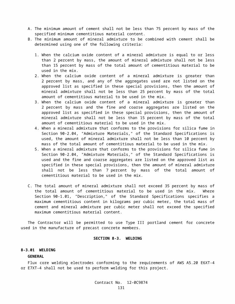
b. The contractor will periodically evaluate the spread of wages paid within each classification to determine any evidence of discriminatory wage practices.
c. The contractor will periodically review selected personnel actions in depth to determine whether there is evidence of discrimination. Where evidence is found, the contractor will promptly take corrective action. If the review indicates that the discrimination may extend beyond the actions reviewed, such corrective action shall include all affected persons.
d. The contractor will promptly investigate all complaints of alleged discrimination made to the contractor in connection with his obligations under this contract, will attempt to resolve such complaints, and will take appropriate corrective action within a reasonable time. If the investigation indicates that the discrimination may affect persons other than the complainant, such corrective action shall include such other persons. Upon completion of each investigation, the contractor will inform every complainant of all of his avenues of appeal.
6. Training and Promotion:
a. The contractor will assist in locating, qualifying, and increasing the skills of minority group and women employees, and applicants for employment.
b. Consistent with the contractor's work force requirements and as permissible under Federal and State regulations, the contractor shall make full use of training programs, i.e., apprenticeship, and on-the-job training programs for the geographical area of contract performance. Where feasible, 25 percent of apprentices or trainees in each occupation shall be in their first year of apprenticeship or training. In the event a special provision for training is provided under this contract, this subparagraph will be superseded as indicated in the special provision.
c. The contractor will advise employees and applicants for employment of available training programs and entrance requirements for each.
d. The contractor will periodically review the training and promotion potential of minority group and women employees and will encourage eligible employees to apply for such training and promotion.
7. Unions: If the contractor relies in whole or in part upon unions as a source of employees, the contractor will use his/her best efforts to obtain the cooperation of such unions to increase opportunities for minority groups and women within the unions, and to effect referrals by such unions of minority and female employees. Actions by the contractor either directly or through a contractor's association acting as agent will include the procedures set forth below:
a. The contractor will use best efforts to develop, in cooperation with the unions, joint training programs aimed toward qualifying more minority group members and women for membership in the unions and increasing the skills of minority group employees and women so that they may qualify for higher paying employment.
b. The contractor will use best efforts to incorporate an EEO clause into each union agreement to the end that such union will be contractually bound to refer applicants without regard to their race, color, religion, sex, national origin, age or disability.
c. The contractor is to obtain information as to the referral practices and policies of the labor union except that to the extent such information is within the exclusive possession of the labor union and such labor union refuses to furnish such information to the contractor, the contractor shall so certify to the SHA and shall set forth what efforts have been made to obtain such information.
d. In the event the union is unable to provide the contractor with a reasonable flow of minority and women referrals within the time limit set forth in the collective bargaining agreement, the contractor will, through independent recruitment efforts, fill the employment vacancies without regard to race, color, religion, sex, national origin, age or disability; making full efforts to obtain qualified and/or qualifiable minority group persons and women. (The DOL has held that it shall be no excuse that the union with which the contractor has a collective bargaining agreement providing for exclusive referral failed to refer minority employees.) In the
Contract No. 12-0C9874133
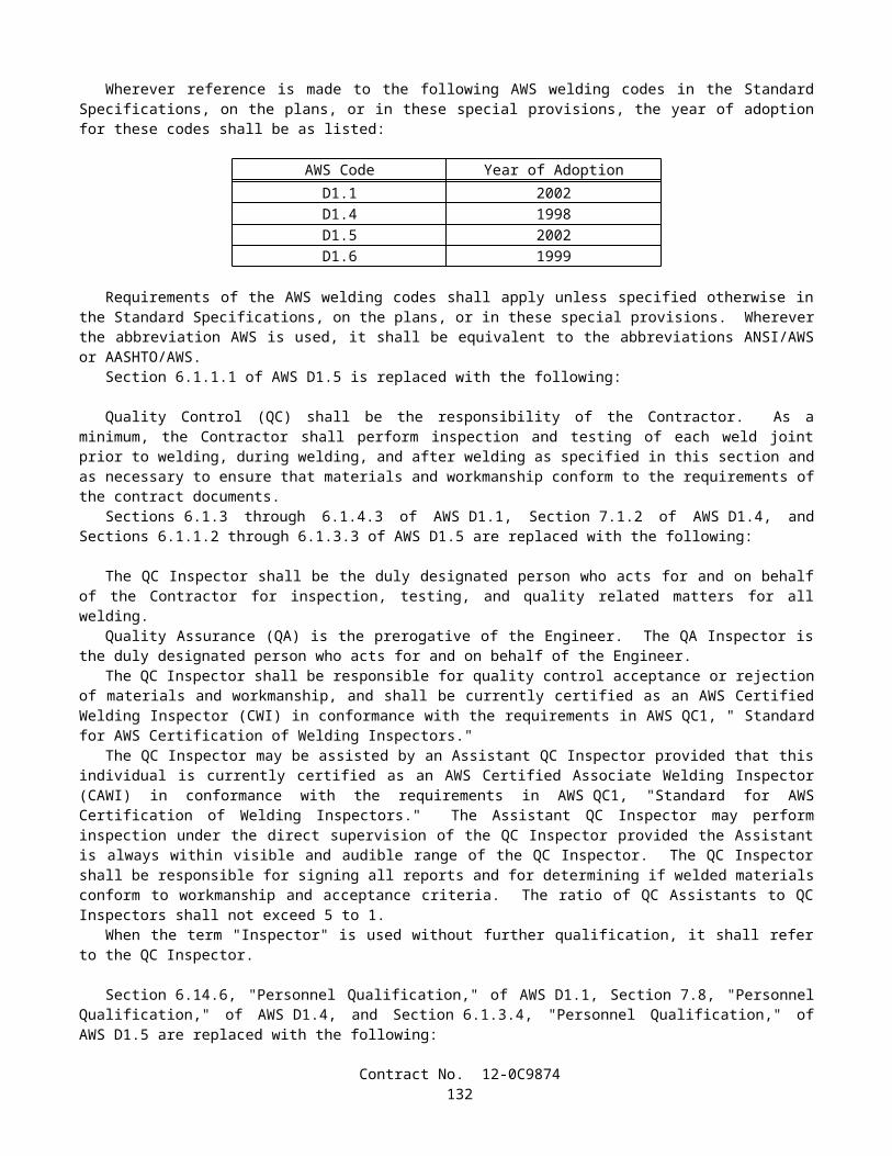
event the union referral practice prevents the contractor from meeting the obligations pursuant to Executive Order 11246, as amended, and these special provisions, such contractor shall immediately notify the SHA.
8. Selection of Subcontractors, Procurement of Materials and Leasing of Equipment: The contractor shall not discriminate on the grounds of race, color, religion, sex, national origin, age or disability in the selection and retention of subcontractors, including procurement of materials and leases of equipment.
a. The contractor shall notify all potential subcontractors and suppliers of his/her EEO obligations under this contract.
b. Disadvantaged business enterprises (DBE), as defined in 49 CFR 23, shall have equal opportunity to compete for and perform subcontracts which the contractor enters into pursuant to this contract. The contractor will use his best efforts to solicit bids from and to utilize DBE subcontractors or subcontractors with meaningful minority group and female representation among their employees. Contractors shall obtain lists of DBE construction firms from SHA personnel.
c. The contractor will use his best efforts to ensure subcontractor compliance with their EEO obligations.
9. Records and Reports: The contractor shall keep such records as necessary to document compliance with the EEO requirements. Such records shall be retained for a period of three years following completion of the contract work and shall be available at reasonable times and places for inspection by authorized representatives of the SHA and the FHWA.
a. The records kept by the contractor shall document the following:
(1) The number of minority and non-minority group members and women employed in each work classification on the project;
(2) The progress and efforts being made in cooperation with unions, when applicable, to increase employment opportunities for minorities and women;
(3) The progress and efforts being made in locating, hiring, training, qualifying, and upgrading minority and female employees; and
(4) The progress and efforts being made in securing the services of DBE subcontractors or subcontractors with meaningful minority and female representation among their employees.
b. The contractors will submit an annual report to the SHA each July for the duration of the project, indicating the number of minority, women, and non-minority group employees currently engaged in each work classification required by the contract work. This information is to be reported on Form FHWA-1391. If on-the-job training is being required by special provision, the contractor will be required to collect and report training data.
III. NONSEGREGATED FACILITIES(Applicable to all Federal-aid construction contracts and to all related subcontracts of $10,000 or more.)
a. By submission of this bid, the execution of this contract or subcontract, or the consummation of this material supply agreement or purchase order, as appropriate, the bidder, Federal-aid construction contractor, subcontractor, material supplier, or vendor, as appropriate, certifies that the firm does not maintain or provide for its employees any segregated facilities at any of its establishments, and that the firm does not permit its employees to perform their services at any location, under its control, where segregated facilities are maintained. The firm agrees that a breach of this certification is a violation of the EEO provisions of this contract. The firm further certifies that no employee will be denied access to adequate facilities on the basis of sex or disability.
b. As used in this certification, the term "segregated facilities" means any waiting rooms, work areas, restrooms and washrooms, restaurants and other eating areas, time clocks, locker rooms, and other storage or dressing areas, parking lots, drinking fountains, recreation or entertainment areas, transportation, and housing facilities provided for employees which are segregated by explicit directive, or are, in fact, segregated on the basis of
Contract No. 12-0C9874134
race, color, religion, national origin, age or disability, because of habit, local custom, or otherwise. The only exception will be for the disabled when the demands for accessibility override (e.g. disabled parking).
c. The contractor agrees that it has obtained or will obtain identical certification from proposed subcontractors or material suppliers prior to award of subcontracts or consummation of material supply agreements of $10,000 or more and that it will retain such certifications in its files.
IV. PAYMENT OF PREDETERMINED MINIMUM WAGE(Applicable to all Federal-aid construction contracts exceeding $2,000 and to all related subcontracts, except for projects
located on roadways classified as local roads or rural minor collectors, which are exempt.)
1. General:
a. All mechanics and laborers employed or working upon the site of the work will be paid unconditionally and not less often than once a week and without subsequent deduction or rebate on any account [except such payroll deductions as are permitted by regulations (29 CFR 3)] issued by the Secretary of Labor under the Copeland Act (40 U.S.C. 276c) the full amounts of wages and bona fide fringe benefits (or cash equivalents thereof) due at time of payment. The payment shall be computed at wage rates not less than those contained in the wage determination of the Secretary of Labor (hereinafter "the wage determination") which is attached hereto and made a part hereof, regardless of any contractual relationship which may be alleged to exist between the contractor or its subcontractors and such laborers and mechanics. The wage determination (including any additional classifications and wage rates conformed under paragraph 2 of this Section IV and the DOL poster (WH-1321) or Form FHWA-1495) shall be posted at all times by the contractor and its subcontractors at the site of the work in a prominent and accessible place where it can be easily seen by the workers. For the purpose of this Section, contributions made or costs reasonably anticipated for bona fide fringe benefits under Section 1(b)(2) of the Davis-Bacon Act (40 U.S.C. 276a) on behalf of laborers or mechanics are considered wages paid to such laborers or mechanics, subject to the provisions of Section IV, paragraph 3b, hereof. Also, for the purpose of this Section, regular contributions made or costs incurred for more than a weekly period (but not less often than quarterly) under plans, funds, or programs, which cover the particular weekly period, are deemed to be constructively made or incurred during such weekly period. Such laborers and mechanics shall be paid the appropriate wage rate and fringe benefits on the wage determination for the classification of work actually performed, without regard to skill, except as provided in paragraphs 4 and 5 of this Section IV.
b. Laborers or mechanics performing work in more than one classification may be compensated at the rate specified for each classification for the time actually worked therein, provided, that the employer's payroll records accurately set forth the time spent in each classification in which work is performed.
c. All rulings and interpretations of the Davis-Bacon Act and related acts contained in 29 CFR 1, 3, and 5 are herein incorporated by reference in this contract.
2. Classification:
a. The SHA contracting officer shall require that any class of laborers or mechanics employed under the contract, which is not listed in the wage determination, shall be classified in conformance with the wage determination.
b. The contracting officer shall approve an additional classification, wage rate and fringe benefits only when the following criteria have been met:
(1) the work to be performed by the additional classification requested is not performed by a classification in the wage determination;
(2) the additional classification is utilized in the area by the construction industry;
(3) the proposed wage rate, including any bona fide fringe benefits, bears a reasonable relationship to the wage rates contained in the wage determination; and
(4) with respect to helpers, when such a classification prevails in the area in which the work is performed.
Contract No. 12-0C9874135
c. If the contractor or subcontractors, as appropriate, the laborers and mechanics (if known) to be employed in the additional classification or their representatives, and the contracting officer agree on the classification and wage rate (including the amount designated for fringe benefits where appropriate), a report of the action taken shall be sent by the contracting officer to the DOL, Administrator of the Wage and Hour Division, Employment Standards Administration, Washington, D.C. 20210. The Wage and Hour Administrator, or an authorized representative, will approve, modify, or disapprove every additional classification action within 30 days of receipt and so advise the contracting officer or will notify the contracting officer within the 30-day period that additional time is necessary.
d. In the event the contractor or subcontractors, as appropriate, the laborers or mechanics to be employed in the additional classification or their representatives, and the contracting officer do not agree on the proposed classification and wage rate (including the amount designated for fringe benefits, where appropriate), the contracting officer shall refer the questions, including the views of all interested parties and the recommendation of the contracting officer, to the Wage and Hour Administrator for determination. Said Administrator, or an authorized representative, will issue a determination within 30 days of receipt and so advise the contracting officer or will notify the contracting officer within the 30-day period that additional time is necessary
e. The wage rate (including fringe benefits where appropriate) determined pursuant to paragraph 2c or 2d of this Section IV shall be paid to all workers performing work in the additional classification from the first day on which work is performed in the classification.
3. Payment of Fringe Benefits:
a. Whenever the minimum wage rate prescribed in the contract for a class of laborers or mechanics includes a fringe benefit which is not expressed as an hourly rate, the contractor or subcontractors, as appropriate, shall either pay the benefit as stated in the wage determination or shall pay another bona fide fringe benefit or an hourly case equivalent thereof.
b. If the contractor or subcontractor, as appropriate, does not make payments to a trustee or other third person, he/she may consider as a part of the wages of any laborer or mechanic the amount of any costs reasonably anticipated in providing bona fide fringe benefits under a plan or program, provided, that the Secretary of Labor has found, upon the written request of the contractor, that the applicable standards of the Davis-Bacon Act have been met. The Secretary of Labor may require the contractor to set aside in a separate account assets for the meeting of obligations under the plan or program.
4. Apprentices and Trainees (Programs of the U.S. DOL) and Helpers:
a. Apprentices:
(1) Apprentices will be permitted to work at less than the predetermined rate for the work they performed when they are employed pursuant to and individually registered in a bona fide apprenticeship program registered with the DOL, Employment and Training Administration, Bureau of Apprenticeship and Training, or with a State apprenticeship agency recognized by the Bureau, or if a person is employed in his/her first 90 days of probationary employment as an apprentice in such an apprenticeship program, who is not individually registered in the program, but who has been certified by the Bureau of Apprenticeship and Training or a State apprenticeship agency (where appropriate) to be eligible for probationary employment as an apprentice.
(2) The allowable ratio of apprentices to journeyman-level employees on the job site in any craft classification shall not be greater than the ratio permitted to the contractor as to the entire work force under the registered program. Any employee listed on a payroll at an apprentice wage rate, who is not registered or otherwise employed as stated above, shall be paid not less than the applicable wage rate listed in the wage determination for the classification of work actually performed. In addition, any apprentice performing work on the job site in excess of the ratio permitted under the registered program shall be paid not less than the applicable wage rate on the wage determination for the work actually performed. Where a contractor or subcontractor is performing construction on a project in a locality other than that in which its program is
Contract No. 12-0C9874136

registered, the ratios and wage rates (expressed in percentages of the journeyman-level hourly rate) specified in the contractor's or subcontractor's registered program shall be observed.
(3) Every apprentice must be paid at not less than the rate specified in the registered program for the apprentice's level of progress, expressed as a percentage of the journeyman-level hourly rate specified in the applicable wage determination. Apprentices shall be paid fringe benefits in accordance with the provisions of the apprenticeship program. If the apprenticeship program does not specify fringe benefits, apprentices must be paid the full amount of fringe benefits listed on the wage determination for the applicable classification. If the Administrator for the Wage and Hour Division determines that a different practice prevails for the applicable apprentice classification, fringes shall be paid in accordance with that determination.
(4) In the event the Bureau of Apprenticeship and Training, or a State apprenticeship agency recognized by the Bureau, withdraws approval of an apprenticeship program, the contractor or subcontractor will no longer be permitted to utilize apprentices at less than the applicable predetermined rate for the comparable work performed by regular employees until an acceptable program is approved.
b. Trainees:
(1) Except as provided in 29 CFR 5.16, trainees will not be permitted to work at less than the predetermined rate for the work performed unless they are employed pursuant to and individually registered in a program which has received prior approval, evidenced by formal certification by the DOL, Employment and Training Administration.
(2) The ratio of trainees to journeyman-level employees on the job site shall not be greater than permitted under the plan approved by the Employment and Training Administration. Any employee listed on the payroll at a trainee rate who is not registered and participating in a training plan approved by the Employment and Training Administration shall be paid not less than the applicable wage rate on the wage determination for the classification of work actually performed. In addition, any trainee performing work on the job site in excess of the ratio permitted under the registered program shall be paid not less than the applicable wage rate on the wage determination for the work actually performed.
(3) Every trainee must be paid at not less than the rate specified in the approved program for his/her level of progress, expressed as a percentage of the journeyman-level hourly rate specified in the applicable wage determination. Trainees shall be paid fringe benefits in accordance with the provisions of the trainee program. If the trainee program does not mention fringe benefits, trainees shall be paid the full amount of fringe benefits listed on the wage determination unless the Administrator of the Wage and Hour Division determines that there is an apprenticeship program associated with the corresponding journeyman-level wage rate on the wage determination which provides for less than full fringe benefits for apprentices, in which case such trainees shall receive the same fringe benefits as apprentices.
(4) In the event the Employment and Training Administration withdraws approval of a training program, the contractor or subcontractor will no longer be permitted to utilize trainees at less than the applicable predetermined rate for the work performed until an acceptable program is approved.
c. Helpers:
Helpers will be permitted to work on a project if the helper classification is specified and defined on the applicable wage determination or is approved pursuant to the conformance procedure set forth in Section IV.2. Any worker listed on a payroll at a helper wage rate, who is not a helper under an approved definition, shall be paid not less than the applicable wage rate on the wage determination for the classification of work actually performed.
5. Apprentices and Trainees (Programs of the U.S. DOT):Apprentices and trainees working under apprenticeship and skill training programs which have been certified by the Secretary of Transportation as promoting EEO in connection with Federal-aid highway construction programs are not subject to the requirements of paragraph 4 of this Section IV. The straight time hourly wage rates for
Contract No. 12-0C9874137
apprentices and trainees under such programs will be established by the particular programs. The ratio of apprentices and trainees to journeymen shall not be greater than permitted by the terms of the particular program.
6. Withholding:The SHA shall upon its own action or upon written request of an authorized representative of the DOL withhold, or cause to be withheld, from the contractor or subcontractor under this contract or any other Federal contract with the same prime contractor, or any other Federally-assisted contract subject to Davis-Bacon prevailing wage requirements which is held by the same prime contractor, as much of the accrued payments or advances as may be considered necessary to pay laborers and mechanics, including apprentices, trainees, and helpers, employed by the contractor or any subcontractor the full amount of wages required by the contract. In the event of failure to pay any laborer or mechanic, including any apprentice, trainee, or helper, employed or working on the site of the work, all or part of the wages required by the contract, the SHA contracting officer may, after written notice to the contractor, take such action as may be necessary to cause the suspension of any further payment, advance, or guarantee of funds until such violations have ceased.
7. Overtime Requirements:No contractor or subcontractor contracting for any part of the contract work which may require or involve the employment of laborers, mechanics, watchmen, or guards (including apprentices, trainees, and helpers described in paragraphs 4 and 5 above) shall require or permit any laborer, mechanic, watchman, or guard in any workweek in which he/she is employed on such work, to work in excess of 40 hours in such workweek unless such laborer, mechanic, watchman, or guard receives compensation at a rate not less than one-and-one-half times his/her basic rate of pay for all hours worked in excess of 40 hours in such workweek.
8. Violation:Liability for Unpaid Wages; Liquidated Damages: In the event of any violation of the clause set forth in paragraph 7 above, the contractor and any subcontractor responsible thereof shall be liable to the affected employee for his/her unpaid wages. In addition, such contractor and subcontractor shall be liable to the United States (in the case of work done under contract for the District of Columbia or a territory, to such District or to such territory) for liquidated damages. Such liquidated damages shall be computed with respect to each individual laborer, mechanic, watchman, or guard employed in violation of the clause set forth in paragraph 7, in the sum of $10 for each calendar day on which such employee was required or permitted to work in excess of the standard work week of 40 hours without payment of the overtime wages required by the clause set forth in paragraph 7.
9. Withholding for Unpaid Wages and Liquidated Damages:The SHA shall upon its own action or upon written request of any authorized representative of the DOL withhold, or cause to be withheld, from any monies payable on account of work performed by the contractor or subcontractor under any such contract or any other Federal contract with the same prime contractor, or any other Federally-assisted contract subject to the Contract Work Hours and Safety Standards Act, which is held by the same prime contractor, such sums as may be determined to be necessary to satisfy any liabilities of such contractor or subcontractor for unpaid wages and liquidated damages as provided in the clause set forth in paragraph 8 above.
V. STATEMENTS AND PAYROLLS (Applicable to all Federal-aid construction contracts exceeding $2,000 and to all related subcontracts, except for projects
located on roadways classified as local roads or rural collectors, which are exempt.)
1. Compliance with Copeland Regulations (29 CFR 3):
The contractor shall comply with the Copeland Regulations of the Secretary of Labor which are herein incorporated by reference.
2. Payrolls and Payroll Records:
a. Payrolls and basic records relating thereto shall be maintained by the contractor and each subcontractor during the course of the work and preserved for a period of 3 years from the date of completion of the contract for all laborers, mechanics, apprentices, trainees, watchmen, helpers, and guards working at the site of the work.
b. The payroll records shall contain the name, social security number, and address of each such employee; his or her correct classification; hourly rates of wages paid (including rates of contributions or costs anticipated for
Contract No. 12-0C9874138
bona fide fringe benefits or cash equivalent thereof the types described in Section 1(b)(2)(B) of the Davis Bacon Act); daily and weekly number of hours worked; deductions made; and actual wages paid. In addition, for Appalachian contracts, the payroll records shall contain a notation indicating whether the employee does, or does not, normally reside in the labor area as defined in Attachment A, paragraph 1. Whenever the Secretary of Labor, pursuant to Section IV, paragraph 3b, has found that the wages of any laborer or mechanic include the amount of any costs reasonably anticipated in providing benefits under a plan or program described in Section 1(b)(2)(B) of the Davis Bacon Act, the contractor and each subcontractor shall maintain records which show that the commitment to provide such benefits is enforceable, that the plan or program is financially responsible, that the plan or program has been communicated in writing to the laborers or mechanics affected, and show the cost anticipated or the actual cost incurred in providing benefits. Contractors or subcontractors employing apprentices or trainees under approved programs shall maintain written evidence of the registration of apprentices and trainees, and ratios and wage rates prescribed in the applicable programs.
c. Each contractor and subcontractor shall furnish, each week in which any contract work is performed, to the SHA resident engineer a payroll of wages paid each of its employees (including apprentices, trainees, and helpers, described in Section IV, paragraphs 4 and 5, and watchmen and guards engaged on work during the preceding weekly payroll period). The payroll submitted shall set out accurately and completely all of the information required to be maintained under paragraph 2b of this Section V. This information may be submitted in any form desired. Optional Form WH-347 is available for this purpose and may be purchased from the Superintendent of Documents (Federal stock number 029-005-0014-1), U.S. Government Printing Office, Washington, D.C. 20402. The prime contractor is responsible for the submission of copies of payrolls by all subcontractors.
d. Each payroll submitted shall be accompanied by a "Statement of Compliance," signed by the contractor or subcontractor or his/her agent who pays or supervises the payment of the persons employed under the contract and shall certify the following:
(1) that the payroll for the payroll period contains the information required to be maintained under paragraph 2b of this Section V and that such information is correct and complete;
(2) that such laborer or mechanic (including each helper, apprentice, and trainee) employed on the contract during the payroll period has been paid the full weekly wages earned, without rebate, either directly or indirectly, and that no deductions have been made either directly or indirectly from the full wages earned, other than permissible deductions as set forth in the Regulations, 29 CFR 3;
(3) that each laborer or mechanic has been paid not less that the applicable wage rate and fringe benefits or cash equivalent for the classification of worked performed, as specified in the applicable wage determination incorporated into the contract.
e. The weekly submission of a properly executed certification set forth on the reverse side of Optional Form WH-347 shall satisfy the requirement for submission of the "Statement of Compliance" required by paragraph 2d of this Section V.
f. The falsification of any of the above certifications may subject the contractor to civil or criminal prosecution under 18 U.S.C. 1001 and 31 U.S.C. 231.
g. The contractor or subcontractor shall make the records required under paragraph 2b of this Section V available for inspection, copying, or transcription by authorized representatives of the SHA, the FHWA, or the DOL, and shall permit such representatives to interview employees during working hours on the job. If the contractor or subcontractor fails to submit the required records or to make them available, the SHA, the FHWA, the DOL, or all may, after written notice to the contractor, sponsor, applicant, or owner, take such actions as may be necessary to cause the suspension of any further payment, advance, or guarantee of funds. Furthermore, failure to submit the required records upon request or to make such records available may be grounds for debarment action pursuant to 29 CFR 5.12.
VI. RECORD OF MATERIALS, SUPPLIES, AND LABOR1. On all Federal-aid contracts on the National Highway System, except those which provide solely for the installation
of protective devices at railroad grade crossings, those which are constructed on a force account or direct labor basis, Contract No. 12-0C9874
139

highway beautification contracts, and contracts for which the total final construction cost for roadway and bridge is less than $1,000,000 (23 CFR 635) the contractor shall:
a. Become familiar with the list of specific materials and supplies contained in Form FHWA-47, "Statement of Materials and Labor Used by Contractor of Highway Construction Involving Federal Funds," prior to the commencement of work under this contract.
b. Maintain a record of the total cost of all materials and supplies purchased for and incorporated in the work, and also of the quantities of those specific materials and supplies listed on Form FHWA-47, and in the units shown on Form FHWA-47.
c. Furnish, upon the completion of the contract, to the SHA resident engineer on Form FHWA-47 together with the data required in paragraph 1b relative to materials and supplies, a final labor summary of all contract work indicating the total hours worked and the total amount earned.
2. At the prime contractor's option, either a single report covering all contract work or separate reports for the contractor and for each subcontract shall be submitted.
VII. SUBLETTING OR ASSIGNING THE CONTRACT1. The contractor shall perform with its own organization contract work amounting to not less than 30 percent (or a
greater percentage if specified elsewhere in the contract) of the total original contract price, excluding any specialty items designated by the State. Specialty items may be performed by subcontract and the amount of any such specialty items performed may be deducted from the total original contract price before computing the amount of work required to be performed by the contractor's own organization (23 CFR 635).
a. "Its own organization" shall be construed to include only workers employed and paid directly by the prime contractor and equipment owned or rented by the prime contractor, with or without operators. Such term does not include employees or equipment of a subcontractor, assignee, or agent of the prime contractor.
b. "Specialty Items" shall be construed to be limited to work that requires highly specialized knowledge, abilities, or equipment not ordinarily available in the type of contracting organizations qualified and expected to bid on the contract as a whole and in general are to be limited to minor components of the overall contract.
2. The contract amount upon which the requirements set forth in paragraph 1 of Section VII is computed includes the cost of material and manufactured products which are to be purchased or produced by the contractor under the contract provisions.
3. The contractor shall furnish (a) a competent superintendent or supervisor who is employed by the firm, has full authority to direct performance of the work in accordance with the contract requirements, and is in charge of all construction operations (regardless of who performs the work) and (b) such other of its own organizational resources (supervision, management, and engineering services) as the SHA contracting officer determines is necessary to assure the performance of the contract.
4. No portion of the contract shall be sublet, assigned or otherwise disposed of except with the written consent of the SHA contracting officer, or authorized representative, and such consent when given shall not be construed to relieve the contractor of any responsibility for the fulfillment of the contract. Written consent will be given only after the SHA has assured that each subcontract is evidenced in writing and that it contains all pertinent provisions and requirements of the prime contract.
VIII. SAFETY - ACCIDENT PREVENTION1. In the performance of this contract the contractor shall comply with all applicable Federal, State, and local laws
governing safety, health, and sanitation (23 CFR 635). The contractor shall provide all safeguards, safety devices and protective equipment and take any other needed actions as it determines, or as the SHA contracting officer may determine, to be reasonably necessary to protect the life and health of employees on the job and the safety of the public and to protect property in connection with the performance of the work covered by the contract.
Contract No. 12-0C9874140
2. It is a condition of this contract, and shall be made a condition of each subcontract, which the contractor enters into pursuant to this contract, that the contractor and any subcontractor shall not permit any employee, in performance of the contract, to work in surroundings or under conditions which are unsanitary, hazardous or dangerous to his/her health or safety, as determined under construction safety and health standards (29 CFR 1926) promulgated by the Secretary of Labor, in accordance with Section 107 of the Contract Work Hours and Safety Standards Act (40 U.S.C. 333).
3. Pursuant to 29 CFR 1926.3, it is a condition of this contract that the Secretary of Labor or authorized representative thereof, shall have right of entry to any site of contract performance to inspect or investigate the matter of compliance with the construction safety and health standards and to carry out the duties of the Secretary under Section 107 of the Contract Work Hours and Safety Standards Act (40 U.S.C. 333).
IX. FALSE STATEMENTS CONCERNING HIGHWAY PROJECTSIn order to assure high quality and durable construction in conformity with approved plans and specifications and a high
degree of reliability on statements and representations made by engineers, contractors, suppliers, and workers on Federal-aid highway projects, it is essential that all persons concerned with the project perform their functions as carefully, thoroughly, and honestly as possible. Willful falsification, distortion, or misrepresentation with respect to any facts related to the project is a violation of Federal law. To prevent any misunderstanding regarding the seriousness of these and similar acts, the following notice shall be posted on each Federal-aid highway project (23 CFR 635) in one or more places where it is readily available to all persons concerned with the project:
Notice To All Personnel Engaged On Federal-Aid Highway Projects
18 U.S.C. 1020 READS AS FOLLOWS:
"Whoever being an officer, agent, or employee of the United States, or any State or Territory, or whoever, whether a person, association, firm, or corporation, knowingly makes any false statement, false representation, or false report as to the character, quality, quantity, or cost of the material used or to be used, or the quantity or quality of the work performed or to be performed, or the cost thereof in connection with the submission of plans, maps, specifications, contracts, or costs of construction on any highway or related project submitted for approval to the Secretary of Transportation; or
Whoever knowingly makes any false statement, false representation, false report or false claim with respect to the character, quality, quantity, or cost of any work performed or to be performed, or materials furnished or to be furnished, in connection with the construction of any highway or related project approved by the Secretary of Transportation; or
Whoever knowingly makes any false statement or false representation as to material fact in any statement, certificate, or report submitted pursuant to provisions of the Federal-aid Roads Act approved July 1, 1916, (39 Stat. 355), as amended and supplemented;
Shall be fined not more that $10,000 or imprisoned not more than 5 years or both."
X. IMPLEMENTATION OF CLEAN AIR ACT AND FEDERAL WATER POLLUTION CONTROL ACT (Applicable to all Federal-aid construction contracts and to all related subcontracts of $100,000 or more.)
By submission of this bid or the execution of this contract, or subcontract, as appropriate, the bidder, Federal-aid construction contractor, or subcontractor, as appropriate, will be deemed to have stipulated as follows:
1. That any facility that is or will be utilized in the performance of this contract, unless such contract is exempt under the Clean Air Act, as amended (42 U.S.C. 1857 et seq., as amended by Pub.L. 91-604), and under the Federal Water Pollution Control Act, as amended (33 U.S.C. 1251 et seq., as amended by Pub.L. 92-500), Executive Order 11738, and regulations in implementation thereof (40 CFR 15) is not listed, on the date of contract award, on the U.S. Environmental Protection Agency (EPA) List of Violating Facilities pursuant to 40 CFR 15.20.
2. That the firm agrees to comply and remain in compliance with all the requirements of Section 114 of the Clean Air Act and Section 308 of the Federal Water Pollution Control Act and all regulations and guidelines listed thereunder.
Contract No. 12-0C9874141
3. That the firm shall promptly notify the SHA of the receipt of any communication from the Director, Office of Federal Activities, EPA, indicating that a facility that is or will be utilized for the contract is under consideration to be listed on the EPA List of Violating Facilities.
4. That the firm agrees to include or cause to be included the requirements of paragraph 1 through 4 of this Section X in every nonexempt subcontract, and further agrees to take such action as the government may direct as a means of enforcing such requirements.
XI. CERTIFICATION REGARDING DEBARMENT, SUSPENSION, INELIGIBILITY AND VOLUNTARY EXCLUSION
1. Instructions for Certification - Primary Covered Transactions:(Applicable to all Federal-aid contracts - 49 CFR 29)
a. By signing and submitting this proposal, the prospective primary participant is providing the certification set out below.
b. The inability of a person to provide the certification set out below will not necessarily result in denial of participation in this covered transaction. The prospective participant shall submit an explanation of why it cannot provide the certification set out below. The certification or explanation will be considered in connection with the department or agency's determination whether to enter into this transaction. However, failure of the prospective primary participant to furnish a certification or an explanation shall disqualify such a person from participation in this transaction.
c. The certification in this clause is a material representation of fact upon which reliance was placed when the department or agency determined to enter into this transaction. If it is later determined that the prospective primary participant knowingly rendered an erroneous certification, in addition to other remedies available to the Federal Government, the department or agency may terminate this transaction for cause of default.
d. The prospective primary participant shall provide immediate written notice to the department or agency to whom this proposal is submitted if any time the prospective primary participant learns that its certification was erroneous when submitted or has become erroneous by reason of changed circumstances.
e. The terms "covered transaction," "debarred," "suspended," "ineligible," "lower tier covered transaction," "participant," "person," "primary covered transaction," "principal," "proposal," and "voluntarily excluded," as used in this clause, have the meanings set out in the Definitions and Coverage sections of rules implementing Executive Order 12549. You may contact the department or agency to which this proposal is submitted for assistance in obtaining a copy of those regulations.
f. The prospective primary participant agrees by submitting this proposal that, should the proposed covered transaction be entered into, it shall not knowingly enter into any lower tier covered transaction with a person who is debarred, suspended, declared ineligible, or voluntarily excluded from participation in this covered transaction, unless authorized by the department or agency entering into this transaction.
g. The prospective primary participant further agrees by submitting this proposal that it will include the clause titled "Certification Regarding Debarment, Suspension, Ineligibility and Voluntary Exclusion-Lower Tier Covered Transaction," provided by the department or agency entering into this covered transaction, without modification, in all lower tier covered transactions and in all solicitations for lower tier covered transactions.
h. A participant in a covered transaction may rely upon a certification of a prospective participant in a lower tier covered transaction that is not debarred, suspended, ineligible, or voluntarily excluded from the covered transaction, unless it knows that the certification is erroneous. A participant may decide the method and frequency by which it determines the eligibility of its principals. Each participant may, but is not required to, check the nonprocurement portion of the "Lists of Parties Excluded From Federal Procurement or Nonprocurement Programs" (Nonprocurement List) which is compiled by the General Services Administration.
i. Nothing contained in the foregoing shall be construed to require establishment of a system of records in order to render in good faith the certification required by this clause. The knowledge and information of participant is
Contract No. 12-0C9874142
not required to exceed that which is normally possessed by a prudent person in the ordinary course of business dealings.
j. Except for transactions authorized under paragraph f of these instructions, if a participant in a covered transaction knowingly enters into a lower tier covered transaction with a person who is suspended, debarred, ineligible, or voluntarily excluded from participation in this transaction, in addition to other remedies available to the Federal Government, the department or agency may terminate this transaction for cause or default.
2. Certification Regarding Debarment, Suspension, Ineligibility and Voluntary Exclusion — Primary Covered Transactions:
a. The prospective primary participant certifies to the best of its knowledge and belief, that it and its principals:
(1) Are not presently debarred, suspended, proposed for debarment, declared ineligible, or voluntarily excluded from covered transactions by any Federal department or agency;
(2) Have not within a 3-year period preceding this proposal been convicted of or had a civil judgement rendered against them for commission of fraud or a criminal offense in connection with obtaining, attempting to obtain, or performing a public (Federal, State or local) transaction or contract under a public transaction; violation of Federal or State antitrust statutes or commission of embezzlement, theft, forgery, bribery, falsification or destruction of records, making false statements, or receiving stolen property;
(3) Are not presently indicted for or otherwise criminally or civilly charged by a governmental entity (Federal, State or local) with commission of any of the offenses enumerated in paragraph 1b of this certification; and
(4) Have not within a 3-year period preceding this application/proposal had one or more public transactions (Federal, State or local) terminated for cause or default.
b. Where the prospective primary participant is unable to certify to any of the statements in this certification, such prospective participant shall attach an explanation to this proposal.
3. Instructions for Certification - Lower Tier Covered Transactions:(Applicable to all subcontracts, purchase orders and other lower tier transactions of $25,000 or more - 49 CFR 29)
a. By signing and submitting this proposal, the prospective lower tier is providing the certification set out below.
b. The certification in this clause is a material representation of fact upon which reliance was placed when this transaction was entered into. If it is later determined that the prospective lower tier participant knowingly rendered an erroneous certification, in addition to other remedies available to the Federal Government, the department or agency with which this transaction originated may pursue available remedies, including suspension and/or debarment.
c. The prospective lower tier participant shall provide immediate written notice to the person to which this proposal is submitted if at any time the prospective lower tier participant learns that its certification was erroneous by reason of changed circumstances.
d. The terms "covered transaction," "debarred," "suspended," "ineligible," "primary covered transaction," "participant," "person," "principal," "proposal," and "voluntarily excluded," as used in this clause, have the meanings set out in the Definitions and Coverage sections of rules implementing Executive Order 12549. You may contact the person to which this proposal is submitted for assistance in obtaining a copy of those regulations.
e. The prospective lower tier participant agrees by submitting this proposal that, should the proposed covered transaction be entered into, it shall not knowingly enter into any lower tier covered transaction with a person who is debarred, suspended, declared ineligible, or voluntarily excluded from participation in this covered transaction, unless authorized by the department or agency with which this transaction originated.
Contract No. 12-0C9874143
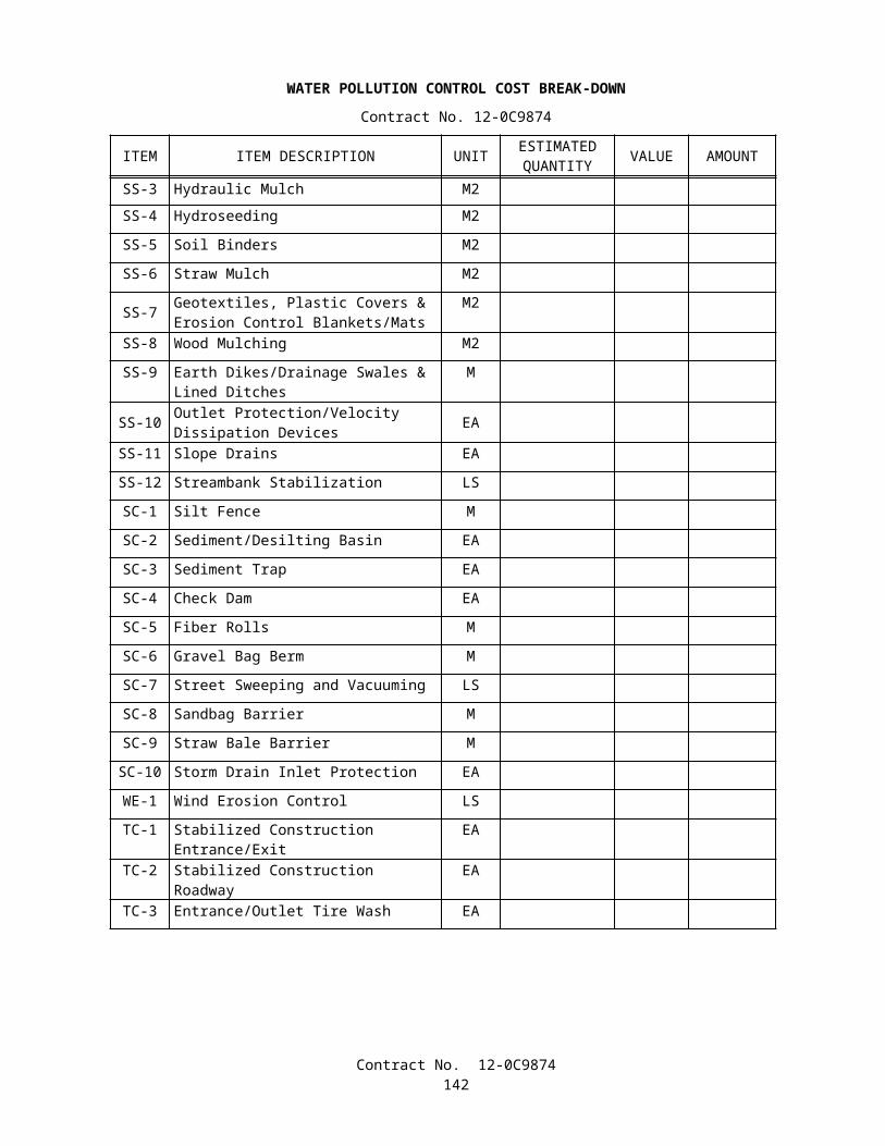
f. The prospective lower tier participant further agrees by submitting this proposal that it will include this clause titled "Certification Regarding Debarment, Suspension, Ineligibility and Voluntary Exclusion-Lower Tier Covered Transaction," without modification, in all lower tier covered transactions and in all solicitations for lower tier covered transactions.
g. A participant in a covered transaction may rely upon a certification of a prospective participant in a lower tier covered transaction that is not debarred, suspended, ineligible, or voluntarily excluded from the covered transaction, unless it knows that the certification is erroneous. A participant may decide the method and frequency by which it determines the eligibility of its principals. Each participant may, but is not required to, check the Nonprocurement List.
h. Nothing contained in the foregoing shall be construed to require establishment of a system of records in order to render in good faith the certification required by this clause. The knowledge and information of participant is not required to exceed that which is normally possessed by a prudent person in the ordinary course of business dealings.
i. Except for transactions authorized under paragraph e of these instructions, if a participant in a covered transaction knowingly enters into a lower tier covered transaction with a person who is suspended, debarred, ineligible, or voluntarily excluded from participation in this transaction, in addition to other remedies available to the Federal Government, the department or agency with which this transaction originated may pursue available remedies, including suspension and/or debarment.
4. Certification Regarding Debarment, Suspension, Ineligibility and Voluntary Exclusion — Lower Tier Covered Transactions:
a. The prospective lower tier participant certifies, by submission of this proposal, that neither it nor its principals is presently debarred, suspended, proposed for debarment, declared ineligible, or voluntarily excluded from participation in this transaction by any Federal department or agency.
b. Where the prospective lower tier participant is unable to certify to any of the statements in this certification, such prospective participant shall attach an explanation to this proposal.
XII. CERTIFICATION REGARDING USE OF CONTRACT FUNDS FOR LOBBYING (Applicable to all Federal-aid construction contracts and to all related subcontracts which exceed $100,000 - 49 CFR 20)
1. The prospective participant certifies, by signing and submitting this bid or proposal, to the best of his or her knowledge and belief, that:
a. No Federal appropriated funds have been paid or will be paid, by or on behalf of the undersigned, to any person for influencing or attempting to influence an officer or employee of any Federal agency, a Member of Congress, an officer or employee of Congress, or an employee of a Member of Congress in connection with the awarding of any Federal contract, the making of any Federal grant, the making of any Federal loan, the entering into of any cooperative agreement, and the extension, continuation, renewal, amendment, or modification of any Federal contract, grant, loan, or cooperative agreement.
b. If any funds other than Federal appropriated funds have been paid or will be paid to any person for influencing or attempting to influence an officer or employee of any Federal agency, a Member of Congress, an officer or employee of Congress, or an employee of a Member of Congress in connection with this Federal contract, grant, loan, or cooperative agreement, the undersigned shall complete and submit Standard Form-LLL, "Disclosure Form to Report Lobbying," in accordance with its instructions.
2. This certification is a material representation of fact upon which reliance was placed when this transaction was made or entered into. Submission of this certification is a prerequisite for making or entering into this transaction imposed by 31 U.S.C. 1352. Any person who fails to file the required certification shall be subject to a civil penalty of not less than $10,000 and not more than $100,000 for each such failure.
Contract No. 12-0C9874144
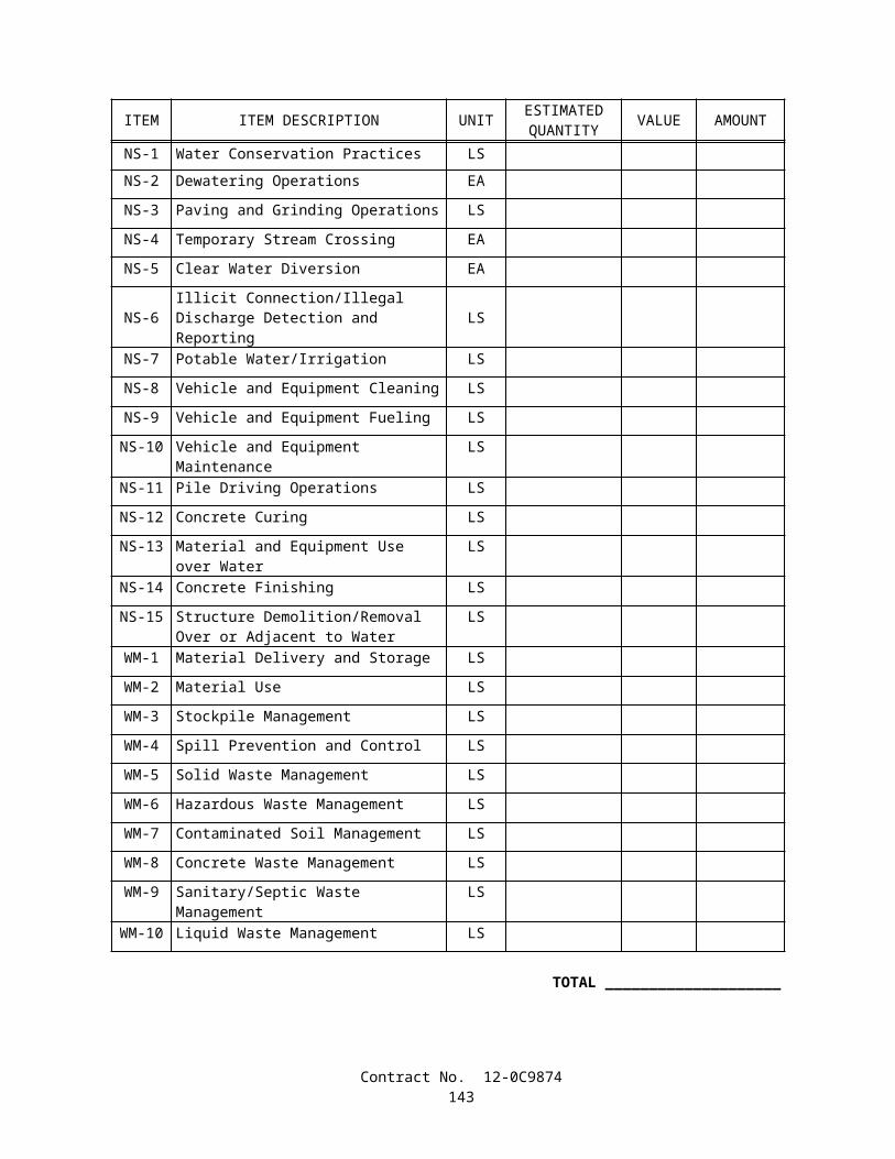
3. The prospective participant also agrees by submitting his or her bid or proposal that he or she shall require that the language of this certification be included in all lower tier subcontracts, which exceed $100,000 and that all such recipients shall certify and disclose accordingly.
Contract No. 12-0C9874145
FEDERAL-AID FEMALE AND MINORITY GOALSIn accordance with Section II, "Nondiscrimination," of "Required Contract Provisions Federal-aid Construction
Contracts" the following are the goals for female utilization:
Goal for Women (applies nationwide)..............(percent) 6.9
The following are goals for minority utilization:
CALIFORNIA ECONOMIC AREAGoal
(Percent)174 Redding, CA:
Non-SMSA Counties 6.8CA Lassen; CA Modoc;CA Plumas;CA Shasta; CA Siskiyou; CA Tehama.
175 Eureka, CANon-SMSA Counties 6.6
CA Del Norte; CA Humboldt; CA Trinity.
176 San Francisco-Oakland-San Jose, CA:SMSA Counties:7120 Salinas-Seaside-Monterey, CA 28.9
CA Monterey.7360 San Francisco-Oakland 25.6
CA Alameda; CA Contra Costa; CA Marin; CA San Francisco; CA San Mateo.7400 San Jose, CA 19.6
CA Santa Clara.7485 Santa Cruz, CA. 14.9
CA Santa Cruz.7500 Santa Rosa, CA 9.1
CA Sonoma.8720 Vallejo-Fairfield- Napa, CA 17.1
CA Napa; CA SolanoNon-SMSA Counties 23.2
CA Lake; CA Mendocino; CA San Benito
177 Sacramento, CA:SMSA Counties:6920 Sacramento, CA 16.1
CA Placer; CA Sacramento; CA Yolo.Non-SMSA Counties 14.3
CA Butte; CA Colusa; CA El Dorado; CA Glenn; CA Nevada; CA Sierra; CA Sutter; CA Yuba.
178 Stockton-Modesto, CA:SMSA Counties:5170 Modesto, CA 12.3
CA Stanislaus.8120 Stockton, CA 24.3
CA San Joaquin.Non-SMSA Counties 19.8
CA Alpine; CA Amador; CA Calaveras; CA Mariposa;CA Merced; CA Tuolumne.
Contract No. 12-0C9874146
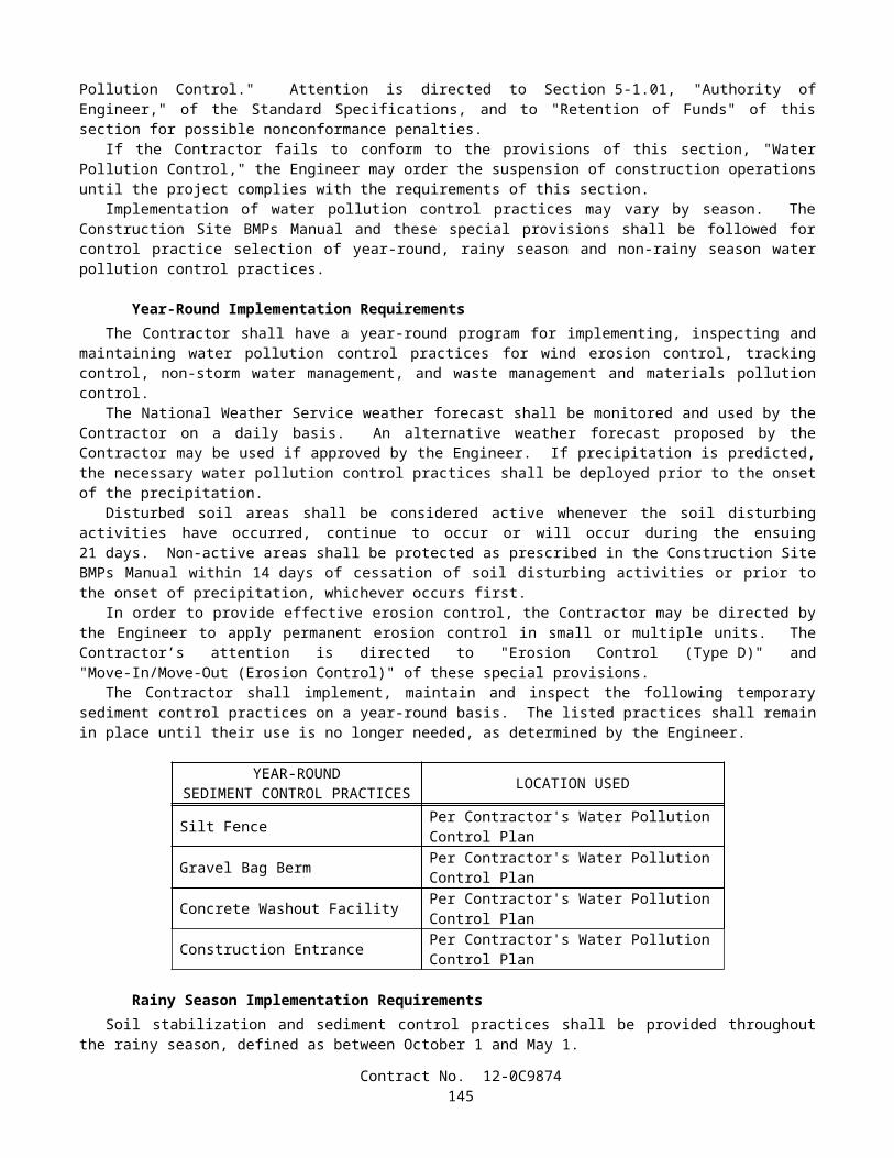
Goal(Percent)
179 Fresno-Bakersfield, CASMSA Counties:0680 Bakersfield, CA 19.1
CA Kern.2840 Fresno, CA 26.1
CA Fresno.Non-SMSA Counties 23.6
CA Kings; CA Madera; CA Tulare.
180 Los Angeles, CA:SMSA Counties:0360 Anaheim-Santa Ana-Garden Grove, CA 11.9
CA Orange.4480 Los Angeles-Long Beach, CA 28.3
CA Los Angeles.6000 Oxnard-Simi Valley-Ventura, CA 21.5
CA Ventura.6780 Riverside-San Bernardino-Ontario, CA. 19.0
CA Riverside; CA San Bernardino.7480 Santa Barbara-Santa Maria-Lompoc, CA 19.7
CA Santa Barbara.Non-SMSA Counties 24.6
CA Inyo; CA Mono; CA San Luis Obispo.
181 San Diego, CA:SMSA Counties7320 San Diego, CA. 16.9
CA San Diego.Non-SMSA Counties 18.2
CA Imperial.
In addition to the reporting requirements set forth elsewhere in this contract the Contractor and subcontractors holding subcontracts, not including material suppliers, of $10,000 or more, shall submit for every month of July during which work is performed, employment data as contained under Form FHWA PR-1391 (Appendix C to 23 CFR, Part 230), and in accordance with the instructions included thereon.
Contract No. 12-0C9874147