Embed Size (px)
Citation preview

7/27/2019 FS 507 Installation
http://slidepdf.com/reader/full/fs-507-installation 1/8
4683-7732-01
INSTALLATION MANUAL
FS-507
Applied Machine:
Finisher
NOTE •Before installing, be sure to unplug the power cord of the machine.
•Keep all packing materials out of the reach of children.
7/27/2019 FS 507 Installation
http://slidepdf.com/reader/full/fs-507-installation 2/8
FS-507
– 1 –
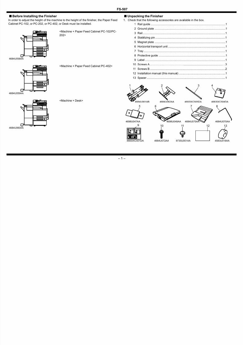
■ Before Installing the Finisher In order to adjust the height of the machine to the height of the finisher, the Paper Feed
Cabinet PC-102, or PC-202, or PC-402, or Desk must be installed.
■ Unpacking the Finisher 1. Check that the following accessories are available in the box.
<Machine + Paper Feed Cabinet PC-102/PC-
202>
4684U058AA
<Machine + Paper Feed Cabinet PC-402>
4684U059AA
<Machine + Desk>
4684U060AA
1 Rail guide ...............................................................................................1
2 Ground plate ..........................................................................................13 Rail .........................................................................................................1
4 Stabilizing pin .........................................................................................1
5 Magnet plate ..........................................................................................1
6 Horizontal transport unit .........................................................................1
7 Tray ........................................................................................................1
8 Protective guide .....................................................................................1
9 Label ......................................................................................................1
10 Screws A ................................................................................................3
11 Screws B ................................................................................................2
12 Installation manual (this manual) ...........................................................1
13 Spacer ....................................................................................................1
5 6 7
12
4683IXC505DA 4683IXC504DA
4698U047AA 4698U048AA 4684U075AA
8
9 10
4684U072AA4683IXC501DA
11
3 4
13
4583U018AA
4684U070AA
1 2
4684U061AB 4684U062AA
9735U001AA

7/27/2019 FS 507 Installation
http://slidepdf.com/reader/full/fs-507-installation 3/8
FS-507
– 2 –
2. Remove all tape and packing brackets.NOTE
• Make sure that the installation site is flat and level.• After the Finisher has been set up, avoid moving it unless it is absolutely neces-
sary.When the Finisher needs to be moved, perform the steps by referring to “Removing the Rail” on p. 6. After the Finisher has been moved, perform the steps given in “Installing the Hori-zontal Transport Unit” on p. 3 and step 5, 6 on p. 4.
4683IXC001DA
Tape
Packingbracket
4643U004AD
NOTE
Do not remove these parts.
C4683U004AA
4643U003AA 4683U013AA
Packing bracket
7/27/2019 FS 507 Installation
http://slidepdf.com/reader/full/fs-507-installation 4/8
FS-507
– 3 –
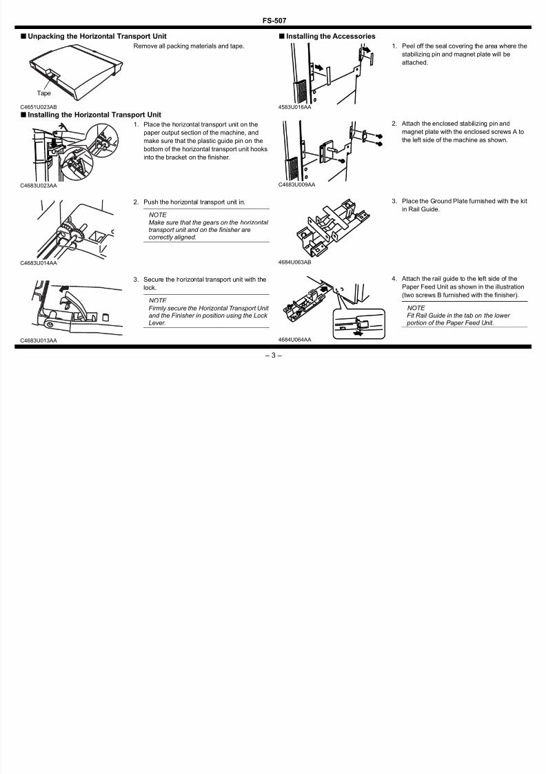
■ Unpacking the Horizontal Transport Unit
■ Installing the Horizontal Transport Unit
■ Installing the Accessories
Remove all packing materials and tape.
C4651U023AB
Tape
1. Place the horizontal transport unit on the
paper output section of the machine, andmake sure that the plastic guide pin on the
bottom of the horizontal transport unit hooks
into the bracket on the finisher.
C4683U023AA
2. Push the horizontal transport unit in.
NOTE
Make sure that the gears on the horizontal transport unit and on the finisher arecorrectly aligned.
C4683U014AA
3. Secure the horizontal transport unit with the
lock.
NOTE
Firmly secure the Horizontal Transport Unit and the Finisher in position using the Lock Lever.
C4683U013AA
1. Peel off the seal covering the area where the
stabilizing pin and magnet plate will be
attached.
4583U016AA
2. Attach the enclosed stabilizing pin and
magnet plate with the enclosed screws A tothe left side of the machine as shown.
C4683U009AA
3. Place the Ground Plate furnished with the kitin Rail Guide.
4684U063AB
4. Attach the rail guide to the left side of the
Paper Feed Unit as shown in the illustration
(two screws B furnished with the finisher).
NOTE Fit Rail Guide in the tab on the lower portion of the Paper Feed Unit.
4684U064AA

7/27/2019 FS 507 Installation
http://slidepdf.com/reader/full/fs-507-installation 5/8
FS-507
– 4 –
■ Adjusting the Height and Tilt of the Finisher 5. Insert the rail into the Rail Guide.
6. Protrude the leading edge of the rail out
about 60 mm to the right from the right end of
the machine.
NOTE
If the rail is pulled out more than necessary,it is caught by the flat spring fitted to themachine as it is brought back into theoriginal position.
7. Insert the spacer that comes with the finisher
into the rail.
NOTE
Slide out the rail to the left and check that it does not come off the Rail Guide.
4684U065AA
4583U017AB
8. Slide the other end of the rail installed in step5 into the rail guide on the finisher.
NOTE
Insert the rail until it snaps into place. At this time, the finisher should stay attached to the machine, even if you try to pull it away.
C4683U010AA
C4683U011AA
1. If the finisher gradually tilts toward the
machine, check the following:
• Are the stabilizing pin and the hole in the fin-
isher at the same height?
• Is the horizontal transport unit not extremely
tilted?
* If the finisher is not at the same height as the
machine, adjust the machine as follows.4684U066AA
2. Slide the finisher away from the machine,and then remove the lower-front cover (two
screws) of the finisher.
4643U021AB
3. Lift the finisher’s two caster covers up, and
then pull them off.
4643U020AA

7/27/2019 FS 507 Installation
http://slidepdf.com/reader/full/fs-507-installation 6/8
FS-507
– 5 –
■ Connecting the Hookup Cord4. Without turning the adjusting bolt (lower bolt)
on the caster, loosen the securing bolt (upper
bolt), and then turn the adjusting bolt (lower
bolt) as indicated below to adjust the height
of the finisher.
<Two rear casters>
If the stabilizing pin is too high:
Turn the bolt clockwise
If the stabilizing pin is too low:
Turn the bolt counterclockwise
<Two front casters>
If the magnet plate is too high:
Turn the bolt clockwise
If the magnet plate is too low:
Turn the bolt counterclockwise
4643U022AB
Securing bolt
Adjustingbolt
5. If the finisher tilts toward the machine, checkthe following:
• Are distances a and b equal?
* If a and b are not equal, refer to step 4 above
and turn the adjusting bolt (lower bolt) as
indicated to adjust the tilt of the finisher.4684U067AA
a
b
6. After the adjustment is finished, without
turning any of the adjusting bolts (lower
bolts), tighten the four securing bolts (upper
bolts).
7. Re-install the caster covers and the lower-
front cover (two screws).
4643U029AA
Securing bolt
Adjusting bolt
1. Remove the connector covers from the
horizontal transport unit and the machine.
2. Connect the hookup cord to the horizontal
transport unit and the machine.
4683IXE003DA
3. Secure the hookup cord of the Horizontal
Transport Unit using the cord clamp (large) of the finisher.
4684U069AA
7/27/2019 FS 507 Installation
http://slidepdf.com/reader/full/fs-507-installation 7/8
FS-507
– 6 –
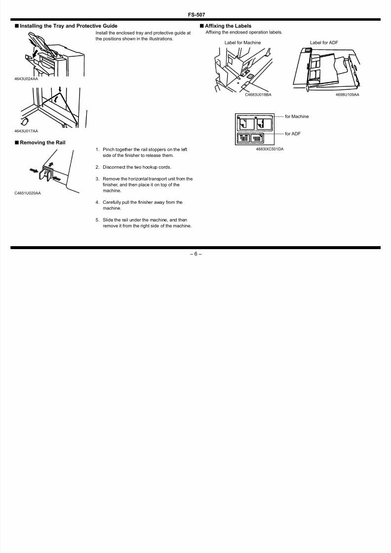
■ Installing the Tray and Protective Guide
■Removing the Rail
■ Affixing the Labels Affixing the enclosed operation labels.Install the enclosed tray and protective guide at
the positions shown in the illustrations.
4643U024AA
4643U017AA
1. Pinch together the rail stoppers on the left
side of the finisher to release them.
2. Disconnect the two hookup cords.
3. Remove the horizontal transport unit from the
finisher, and then place it on top of the
machine.
4. Carefully pull the finisher away from the
machine.
5. Slide the rail under the machine, and then
remove it from the right side of the machine.
C4651U020AA
C4683U018BA
for Machine
4683IXC501DA
4698U109AA
for ADF
Label for ADFLabel for Machine

7/27/2019 FS 507 Installation
http://slidepdf.com/reader/full/fs-507-installation 8/8
FS-507
– 7 –
■ Checking the Hole-Punching Positions1. Plug the power cord into the power outlet and turn on the machine.
2. Load A4 crosswise or Letter crosswise paper (in landscape orientation) into tray 1.
3. Touch “Finishing.”
4. Touch “2-Hole” so that its background changes to black.
■ Adjusting the Hole-Punching Positions
4037IXE523DA
4583IXE507DA
5. Load an A4 crosswise or Letter crosswise
document (blank sheets of paper may be
used) in the document feeding tray.
6. Press the Start key.
7. Fold the paper that is fed out in half, and
check that the punched holes are aligned.
Standard position: ±2 mm
NOTE
If the punched holes are not at their standard positions, adjust the hole- punching position.
4643U031AA
1. Open the upper cover, and then loosen thehole-punching guide securing screw.
Move the green slider to adjust the hole-
punching position.
2. Tighten the securing screw.
3. Close the upper cover.4037IXC175DA
4. Make another test print, and then check that
the punched holes are aligned.
NOTE If the punched holes are not at their standard positions, adjust the hole- punching position.
4643U031AA