Embed Size (px)
Citation preview

Fuel Injection System
1

Introduction The fuel injection system is one of the most important components
in CI engines
The effectiveness of fuel injection system is greatly affects the engine performance with respect to
Power output Fuel economy Smooth engine operation Clean burn
2

Functional Requirements of An Injection System
i. Accurate metering of the fuel injected per cycle
To met changing speed and load requirements of the engine
ii. Correct fuel injection timing in the cycle
To obtain maximum power, ensuring fuel economy and cleanburning
iii. Proper control of rate of injection:
During combustion, desired heat release pattern can be achieved
iv. Proper spray pattern
To ensure rapid mixing of fuel and air
3

Functional Requirements of An Injection System
v. Proper atomization of fuel into very fine droplets.
vi. Uniform distribution of fuel droplets throughout the combustionchamber
vii. To supply equal quantities of metered fuel to all cylinders in case ofmulti cylinder engines
viii. No lag during beginning and end of injection i.e., to eliminatedribbling of fuel droplets into the cylinder
4

5

Classification of Injection Systems
For producing the required pressure for atomizing the fueleither air or a mechanical means is used.
Thus the injection systems can be classified as:
Air injection system
Solid injection systems
6

Air Injection System
Fuel is forced into the cylinder by means of compressed air
It has good mixing of fuel with the air with resultant highermean effective pressure
It has the ability to utilize high viscosity (less expensive)fuels
The system is obsolete due to the requirement of multistageair compressors.
7

Solid Injection System In solid injection system, the liquid fuel is injected directly into the
combustion chamber without the aid of compressed air.
Currently there are two main groups of high-pressure solid injectionsystems
1. Common Rail System (CRS(
2. Unit Injector System (UIS)
All the above systems comprise the following components
Fuel tank , fuel filters, fuel feed pump, injection pump, governors, injectors
8

1. Common Rail System (CRS)
9
Sub functions of a CRFI system
Low pressure circuit High pressure circuit ECU with sensors
COMMON RAIL FUEL INJECTION SYSTEM

Low pressure circuit comprises of Fuel tank, Pre-supply pump, Fuelfilter, And the respective connection lines.
The low –pressure circuit is responsible for transporting the fuel to thehigh –pressure circuit
The Common Rail Sub functions

The Common Rail Sub System
High – pressure circuit comprises: High – pressure pump with pressure control valve The high – pressure accumulator (Rail )with the rail – pressure sensor Injectors, and The respective high – pressure connection lines.
11

The Common Rail Sub System
High pressure circuit
It is the responsibility of the high pressure circuit to generate a constantunvarying high pressure in the high pressure accumulator (the rail)and to inject the fuel through the injectors into the engine’scombustion chambers.
ECU and sensors
The common rail ECU evaluates the signals from the following sensors.Crankshaft – speed sensor, Camshaft sensor, Accelerator-pedaltravel sensor
12
The Common Rail Sub System
13
ECU and sensorsThe sensor are responsible for measuring important physical quantities.The ECU calculates injected fuel quantity, start of injection, duration ofinjection, and rate of discharge curve, as well supervises the correctfunctioning of the injection system as a whole.

Dimension of modern injection technology
14

Common Rail System (CRS) working principle Pressure generation and the injection event are not coupled
Fuel under high pressure is stored inside the rail, which usually consists of a thick-walled closed pipe
A pressure sensor adjusts the desired rail pressure via an additional valve that controls the mass flow of excess fuel back to the fuel tank.
The injection pressure is not dependent on engine speed as UIS does
CRS enables a greater flexibility of injection and mixture formationcompared to injection system driven by camshaft (UIS)
Short pipes connect the rail with the injectors.15

Common Rail System (CRS) working principle
The volume of the rail is large enough to suppress pressure fluctuationsdue to injection.
Injection timing and duration are controlled by solenoid valves and are independent of the pressure generation.
16

Common rail
17
Rail is a forged-steel tube.ID is approx.. 10mmLength is between 280 and 600mm
The volume must be “ as small as possible, as large as necessary”

A typical Common rail injector
18

Common Rail System(CRS) working principle The needle movement is controlled by a solenoid valve
hydraulically.
The spring force Fspring and the hydraulic force F1 of the high pressurefuel on top of the control rod are larger than the hydraulic force F2on the circular ring area, and the needle is kept closed.
As soon as the solenoid valve opens, the pressure in the controlchamber above the control rod decreases and the needle begins toopen, because the inlet throttle connecting the control chamber withthe high-pressure fuel supply is smaller than the outlet throttle.
Excess fuel passes off through the outlet throttle and then flows back to the fuel tank.
19

Common Rail System(CRS) working principle
The opening speed of the needle is determined by the size ratio of both throttles.
The closing process is initiated by closing the solenoid valve.
The pressure inside the control chamber increases and the control rod closes the needle.
The closing speed is again influenced by the size of the throttle.
20

Unit Injector System (UIS) UIS is one in which the pump and the Injector nozzle are combined with
one housing.
In this high pressure injection systems the generation of injection pressureand the injection itself occur synchronously
UIS is driven by a camshaft, which is mechanically coupled with theengine.
A basic characteristic of these systems is the intermittent pressuregeneration: high pressure is only available during a small crank angleinterval.
o Each cylinder is provided with one of these unit injectors21

Unit Injector System (UIS) The omission of the high-pressure pipes between the pump and the
injector allows significantly higher peak injection pressures (about200 MPa and more)
The shape of the cam determines the motion of the plunger and thusthe generation of pressure as a function of crank angle.
The spring at the upper part of the injector presses the plungeragainst the rocker arm and the rocker arm against the cam, andguaranteeing force closure during operation
22

Unit Injector System (UIS)
23

Typical injection rate profiles of common rail and unit injector Due to the large feed rate of the plunger, the injection pressure
strongly increases during injection, resulting in a triangle shapedinjection rate profile
In CRS maximum injection pressure is already present at the startof injection (resulting in a rectangular-shaped injection rate profileand in maximum spray atomization during the complete injectionevent)
24

Unit Pump System (UPS) The functionality of the so-called Unit Pump System (UPS) is practically
identical to that of the unit injector system (UIS) and offers the sameadvantages and disadvantages.
In this system, each cylinder is provided with one pump and oneinjector.
The high-pressure pump is again driven by a camshaft and thus directlycoupled with the engine speed
The high pressure pump plunger is actuated by a cam, and producesthe fuel pressure necessary to open the injector valve at the correcttime.
25

Unit Pump System (UPS) The pump may be placed close to the cylinder or they may be
arranged in cluster
26

Unit Pump System (UPS)The maximum attainable injection pressures of the UPS are smaller thanthose of the UIS.
27

INJECTION PUMP
The main objectives of fuel-injection pump is to deliver accuratelymetered quantity of fuel under high pressure (in the range from 120 to250 MPa) at the correct instant to the injector fitted on each cylinder.
28
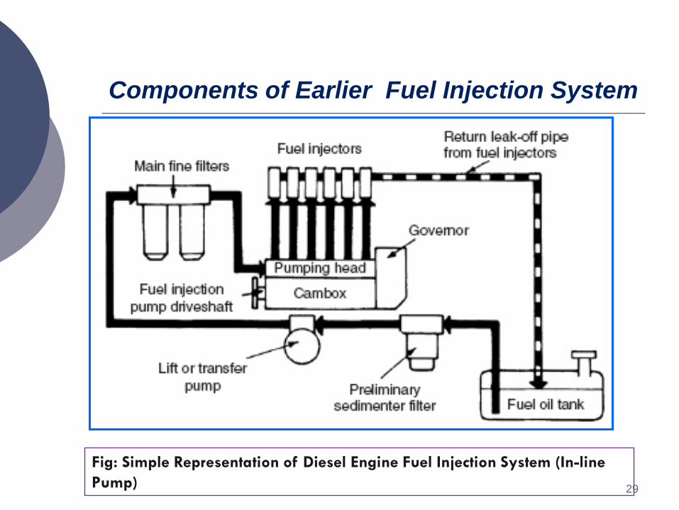
Components of Earlier Fuel Injection System
Fig: Simple Representation of Diesel Engine Fuel Injection System (In-line Pump) 29

Components of Fuel Injection System Fuel filters:
To prevent dust and abrasive particles from entering the pump
Fuel feed pump
To supply fuel from the main fuel tank to the injection system.
Injection pump
To meter and pressurize the fuel for injection,
Governor
To ensure that the amount of fuel injected is in accordance with variation in load,
Injector
To take the fuel from the pump and distribute it in the combustion chamber byatomizing it into fine droplets,
30

Injection pump Governor Fuel delivered by a pump increases with speed the same is
true about the air intake
This results in
Over fueling at higher speeds.
The engine tends to stall at idling speeds (low speeds) dueto insufficiency of fuel.
31

Injection pump Governor
Quantity of fuel delivered increases with load causing excessivecarbon deposits and high exhaust temperature
It is the duty of the injection pump governor to take care of theabove limitation
Governors are generally of two types,
Mechanical governor Pneumatic governor
32

Fuel Injector Fuel injectors atomize the fuel into very fine droplets, and
resulting in better mixing and subsequent combustion
Atomization is done by forcing the fuel through a small orificeunder high pressure.
The injector assembly consists of
a needle valve a compression spring a nozzle an injector body
33

Fuel supplied by the injection pumpexerts sufficient force against thespring to lift the nozzle valve
After injection the spring pressurepushes the nozzle valve back on itsseat
Small quantity of fuel is allowed toleak through the clearance betweennozzle valve and its guide for properlubrication
Valve opening pressure is controlledby adjusting the screw (spring tension)
Fuel Injector
34

Nozzle
The main tasks of the nozzle in combination with the nozzle-holderassembly are to form the rate-of-discharge curve, atomize anddistribute the fuel in the combustion chamber, and seal thehydraulic system from the combustion chamber.
The nozzle construction and design need to be preciselyharmonized with the different engine conditions. These areprimarily:
Combustion processes [direct injection (DI), indirect injection (IDI)] Geometry of the combustion chamber Number of injection jets, the spray shape, and spray direction Injection time Injection rate
35

NOZZLE
The nozzle should fulfill the following functions.
i. Atomization:
This is a very important function since it is the first phasein obtaining proper mixing of the fuel and air in thecombustion chamber.
ii. Distribution of fuel:
Distribution of fuel to the required areas within thecombustion chamber.
36
NOZZLE
Factors affecting fuel distribution
Injection pressure
Density of air in the cylinder
Physical properties of fuel
The properties like self- ignition temperature, vapor pressure, viscosity, etc.
37
NOZZLE
iii. Prevention of impingement on wallso Prevention of the fuel from impinging directly on the walls
of combustion chamber or piston. Fuel striking the walls,decomposes and produces carbon deposits.
This causes smoky exhaust as well as increase in fuelconsumption.
iv. Mixing Mixing the fuel and air in case of non-turbulent type of
combustion chamber should be taken care of by thenozzle.
38

Types of Nozzle
The most common types of Nozzles are:
i. pintle nozzle,
ii. single hole nozzle
iii. multi-hole nozzle,
iv. pintaux nozzle
39

Type of nozzle
(i) Pintle Nozzle:
• It provides a spray operating at low injection pressures of 8-10 Mpa
• The spray cone angle is generally 600
• Advantage of this nozzle is that
• It avoids weak injection and dribbling.
• It prevents the carbon deposition on the nozzle hole.
40

At the centre of the nozzle body there is asingle hole which is closed by the nozzle valve
The size of the hole is usually of the order of0.2 mm.
Injection pressure is of order of 8-10 MPaand spray cone angle is about 150.
Major disadvantage with such nozzle is thatthey tend to dribble
Besides, their spray angle is too narrow tofacilitate good mixing unless highervelocities are used
Single Hole Nozzle
41

Multi-hole Nozzle It consists of a number of holes bored in the
tip of the nozzle.
The number of holes varies from 4 to 18 andthe size from 35 to 200μm.
The hole angle may be from 200 upwards.
These nozzles operate at high injectionpressures of the order of 18 MPa.
Their advantage lies in the ability todistribute the fuel properly even with lowerair motion available in open combustionchambers.
42

Pintaux Nozzle
The needle valve does not lift fully at low speedsand most of the fuel is injected through theauxiliary hole.
Main advantage of this nozzle is better coldstarting performance (20 to 25 °C lower thanmulti hole design).
A major drawback of this nozzle is that itsinjection characteristics are poorer than the multihole nozzle.
It is a type of pintle nozzle which has an auxiliary hole drilled in the nozzlebody
It injects a small amount of fuel through this additional hole (pilot injection) inthe upstream direction slightly before the main injection.
43

Spray Formation At the start of the fuel-injection the
pressure difference across the orifice islow. Therefore single droplets areformed (fig a) .
As the pressure difference increases
i. A stream of fuel emerges from thenozzle (fig b),
ii. The stream encounters aerodynamicresistance from the dense air in thecombustion chamber (fig c)
break-up distance (l3): the length at whicha fuel start forming spray
44

iii. With further and further increase inthe pressure difference, the break-up distance decreases and the coneangle increases until the apex of thecone practically coincides with theorifice
f
cylinjdf
PPCV
ρ)(2 −
=
Where: Cd = coefficient of discharge for the orificePinj = fuel pressure at the inlet to injector, N /m2
Pcyl = pressure of charge inside the cylinder, N/m2
ρf = fuel density, kg/m3
Spray Formation
The fuel jet velocity at the exit of theorifice, Vf, is of the order of 400 m/s. It isgiven by the following equation
45

Larger droplets provide a higher penetration into thechamber but smaller droplets are required for quickmixing and evaporation of the fuel.
The diameter of most of the droplets in a fuel spray is lessthan 5 microns.
Spray formation
46

Spray formation
The droplet sizes depends on various factors which arelisted below
i. Mean droplet size decreases with increase in injectionpressure.
ii. Mean droplet size decreases with increase in air density.
iii. Mean droplet size increases with increase in fuelviscosity.
iv. Size of droplets increases with increase in the size of theorifice.
47

Quantity of Fuel & the Size of Nozzle Orifice
The quantity of the fuel injected per cycle depends to a great extent upon the power output of the engine.
The volume of the fuel injected per second, Q, is given by
( ) ( ) ( )( )orificeoneforperinjectionofNo
injectiononeoftimevelocityjetFuelorificesallofAreaQsec.
×××=
×
×××
×=
6060
36042 i
fN
NVndQ θπ
where : Ni is the number of injections per minute.N for four-stroke engine is rpm/2 and for a two-stroke engine Ni is rpm itselfd is the diameter of one orifice in m,n is the number of orifices,Θ is the duration of injection in crank angle degrees and
48

Quantity of Fuel & the Size of Nozzle Orifice
The rate of fuel injected/degree of crankshaft rotation isa function of
injector camshaft velocity,
the diameter of the injector plunger, and
flow area of the tip orifices.
49

Increasing the rate of injection decreases the duration ofinjection for a given fuel input
A higher rate of injection may permit injection timing to beretarded from optimum value. This helps in maintaining fueleconomy without excessive smoke emission.
However, an increase in injection rate requires an increasedinjection pressure and increases the load on the injector pushrod and the cam. This may affect the durability of the engine.
Quantity of Fuel & the Size of Nozzle Orifice
50