Embed Size (px)
Citation preview

NASA Technical Memorandum 83736
NA_A-TM-83736 19840021809
Fuel Savings Potential of the NASAAdvanced Turboprop Program
J. B. Whitlow, Jr. and G. K. SieversNational Aeronautics and Space AdministrationLewis Research CenterCleveland, Ohio 44135
I _,.,_w,-:v R=SEARCH:L;Ef'_[_-_':LIBR,r,RY_NASA_ -.,l.',_lhlA'i':.'.'.,:_TON__' _ '_ '
Prepared for theAviation Fuel Conservation Symposiumsponsored by the Federal Aviation AdministrationWashington, D.C., September 10-11, 1984
https://ntrs.nasa.gov/search.jsp?R=19840021809 2018-06-04T10:44:56+00:00Z


FUEL SAVINGS POTENTIAL OF THE NASA ADVANCED TURBOPROP PROGRAM
J. B. Whitlow, Jr. and G. K. SieversNational Aeronautics and Space Administration
Lewis Research CenterCleveland, Ohio 44135
k,,?_cS ?Y??
2
FUEL SAVINGS POTENTIAL OF THE NASA ADVANCED TURBOPROP PROGRAM
J. B. Whitlow, Jr. and G. K. Sievers
National Aeronautics and Space AdministrationLewis Research Center
Cleveland, Ohio 44135
SUMMARY
The NASA Advanced Turboprop (ATP) Program is directed at
developing new technology for highly-loaded, multi-bladed pro-
pellers for use at Mach 0.65 to 0.85 and at altitudes compatible
with the air transport system requirements. Advanced turboprop
engines offer the potential of 15 to 30 percent savings in air-
craft block fuel relative to advanced turbofan engines (50 to 60
percent savings over today's turbofan fleet). The program to
develop the technologies needed to implement this potential
fuel savings and an accompanying 7 to 15 percent operating cost
advantage consists of both a small-scale model and analytical
technology effort as well as a test program to evaluate large-
scale hardware. Both single-rotation and counter-rotation
turboprop systems are included. In the counter-rotation area,
both geared systems and a unique gearless pusher configuration
are being pursued. The analytical and subscale model experi-
mental effort includes investigations in the areas of propeller
aeroperformance, aeroelasticity, and acoustics; installation
aerodynamics; cabin environment; and systems integration and
benefit assessment. Advanced gearbox technology will also be
investigated through a program consisting of design studies and
component testing. A major focus of the ATP Program is the

3
design, fabrication, and test of an eight-bladed nine-foot diam-
eter single-rotation propfan for a series of tests to evaluate
the structural, aeroelastic, and acoustic characteristics of
large-scale thin, swept blades. These characteristics cannot
be reliably scaled at the present time from model to large-size.
This large-scale effort, which is needed to validate the design
of the advanced blades and provide data for the improvement of
the analytical prediction capability, will involve both ground
and flight testing. The flight test vehicle will be a modified
Gulfstream II aircraft with the propfan propulsion system
mounted on one wing in a tractor-type installation. In addition
to providing propfan structural and near-field acoustic data,
the flight test will also provide needed data on cabin interior
noise levels. The gearless counter-rotation turboprop propul-
a!
sion system, referred to as the "UnDucted Fan, or simply the
UDF, will also be evaluated in large scale through the ground
test phase. Concurrent counter-rotation engine/flight studies,
a geared C-R model propeller data base, and results from the
gearbox technology program will be used together with the UDF
results to arrive at a decision on which system merits further
support for a possible flight evaluation subsequent to the
single-rotation Propfan Test Assessment (PTA) flight test in
1987.
INTRODUCTION
The fuel consumed by U.S. commercial aviation has tripled
in the pastdecade primarily because of the growing use of jet
aircraft having greatly improved comfort, speed, and reliability

4
over earlier, more fuel conservative but slower aircraft. Al-
though future fuel usage is uncertain, the most conservative
projections indicate more than a doubling of the fuel required
for air transportation by the year 2000.
For many years prior to 1973, jet fuel costs were i0 to 13
cents/gal. Then, in November 1973, previous concerns about a
dwindling petroleum supply were emphasized by the OPEC oil em-
bargo and the resulting energy crisis. This and a subsequent
crisis in Iran led to fuel allocations and a major escalation
in fuel prices. While the fuel allocations have disappeared,
and current fuel supplies are relatively abundant, the fuel
price appears to have stabilized at around $1/gal. Despite a
rise in nonfuel-related cost components included in the direct
operating cost (DOC) computation, fuel costs now account for
over half of the DOC figure for the commercial airline fleet,
whereas in 1972 they accounted for only about one-quarter of
the total. Economic dislocations caused by the high fuel prices
persist and constitute a serious problem for the air transport
industry. Although it is predicted that any further fuel price
increases will be more moderate than in the recent past, empha-
sis on fuel economy is certain to continue as a major factor in
aircraft design for the foreseeable future.
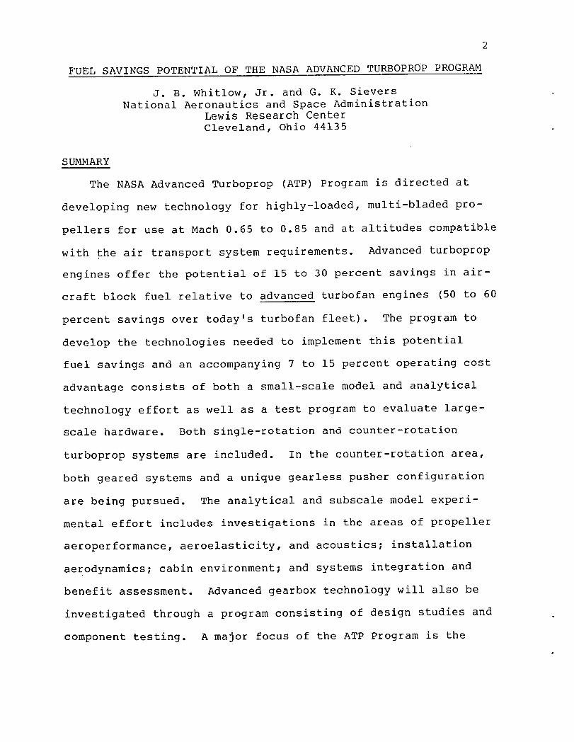
The importance of fuel efficiency in future aircraft designs
leads to a consideration of advanced turboprop concepts. Old
turboprops, such as those found on the Lockheed Electric/P-3
Orion and C-130 (upper left part of fig. i), were fuel efficient
up to airspeeds of slightly over Mach 0.6. Beyond these speeds,
5
however, these propellers experience a rapid increase in com-
pressibility losses due to their thick, unswept, large-diameter
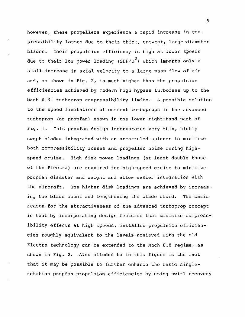
blades. Their propulsion efficiency is high at lower speeds
due to their low power loading (SHP/D 2) which imparts only a
small increase in axial velocity to a large mass flow of air
and, as shown in Fig. 2, is much higher than the propulsion
efficiencies achieved by modern high bypass turbofans up to the
Mach 0.6+ turboprop compressibility limits. A possible solution
to the speed limitations of current turboprops is the advanced
turboprop (or propfan) shown in the lower right-hand part of
Fig. i. This propfan design incorporates very thin, highly
swept blades integrated with an area-ruled spinner to minimize
both compressibility losses and propeller noise during high-
speed cruise. High disk power loadings (at least double those
of the Electra) are required for high-speed cruise to minimize
propfan diameter and weight and allow easier integration with
the aircraft. The higher disk loadings are achieved by increas-
ing the blade count and lengthening the blade chord. The basic
reason for the attractiveness of the advanced turboprop concept
is that by incorporating design features that minimize compress-
ibility effects at high speeds, installed propulsion efficien-
cies roughly equivalent to the levels achieved with the old
Electra technology can be extended to the Mach 0.8 regime, as
shown in Fig. 2. Also alluded to in this figure is the fact
that it may be possible to further enhance the basic single-
rotation propfan propulsion efficiencies by using swirl recovery

6
techniques (e.g., by properly contouring the nacelle/wing in-
stallation) or by using staged, counter-rotating propfans which
can theoretically eliminate the swirl, or nonaxial downstream
velocity component, from the propulsion system stream tube. The
significance of extending turboprop applicability to the Mach
0.8 regime is that these propulsion systems then become candi-
dates for the whole gamut of subsonic aircraft types up to and
including the large commercial transports now powered by turbo-
fan engines. Two possible applications of ATP technology to
these large commercial transports are depicted in Fig. 3. Shown
are a wing-mounted and an aft-mounted tractor installation. Not
shown but also important would be an aft-mount pusher counter-
rotation installation.
As shown in Fig. 4, mission studies comparing transport air-
craft powered by advanced turboprops against similar aircraft
powered by equivalent technology turbofans indicate that ad-
vanced turboprops can produce block fuel savings ranging from
15 to 30 percent. At intermediate stage lengths, fuel savings
of 15 to 20 percent are expected for single rotation propfans
with no swirl recovery, with the benefits depending to some
extent on the choice of cruise speed. Benefits are projected
to be even greater if swirl can be eliminated without excessive
weight penalties, whether by swirl recovery techniques applied
to single-rotation systems or by the use of counter-rotation
propulsion systems. At long stage lengths, the savings are
somewhat greater because the airplane fuel fraction is higher.
Likewise, for short hops the savings are greater because a
7
longer portion of the flight is spent at low speeds where the
turboprop efficiency advantage is greater than at cruise speeds.
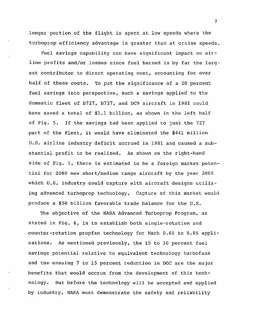
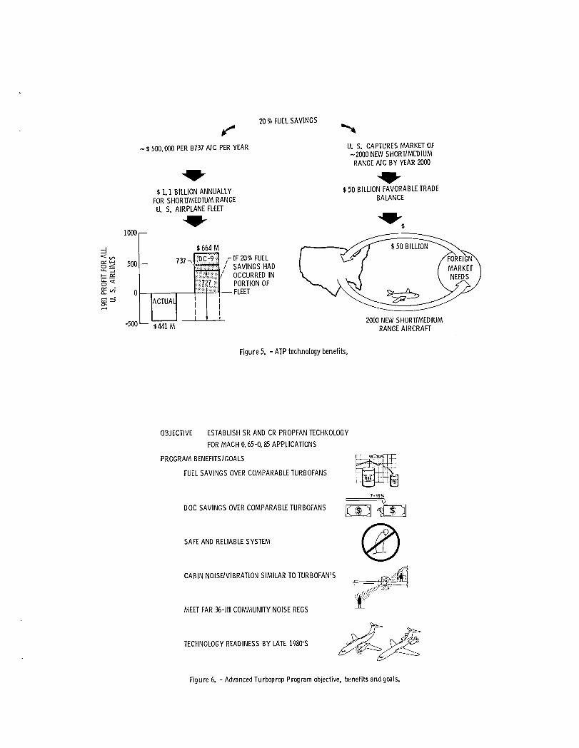
Fuel savings capability can have significant impact on air-
line profits and/or losses since fuel burned is by far the larg-
est contributor to direct operating cost, accounting for over
half of these costs. To put the significance of a 20 percent
fuel savings into perspective, such a savings applied to the
domestic fleet of B727, B737, and DC9 aircraft in 1981 could
have saved a total of $i.i billion, as shown in the left half
of Fig. 5. If the savings had been applied to just the 727
part of the fleet, it would have eliminated the $441 million
U.S. airline industry deficit accrued in 1981 and caused a sub-
stantial profit to be realized. As shown on the right-hand
side of Fig. 5, there is estimated to be a foreign market poten-
tial for 2000 new short/medium range aircraft by the year 2000
which U.S. industry could capture with aircraft designs utiliz-
ing advanced turboprop technology. Capture of this market would
produce a $50 billion favorable trade balance for the O.S.
The objective of the NASA Advanced Turboprop Program, as
stated in Fig. 6, is to establish both single-rotation and
counter-rotation propfan technology for Mach 0.65 to 0.85 appli-
cations. As mentioned previously, the 15 to 30 percent fuel
savings potential relative to equivalent technology turbofans
and the ensuing 7 to 15 percent reduction in DOC are the major
benefits that would accrue from the development of this tech-
nology. But before the technology will be accepted and applied
by industry, NASA must demonstrate the safety and reliability

8
of the critical elements of the system and that cabin noise/
vibration levels similar to today's turbofans can be estab-
lished. To achieve the cabin interior noise goal of 80 to
85 dB, approximately 25 dB of acoustic suppression beyond that
used in current turbofan-powered aircraft will be required.
Consideration alsowill have to be given to isolating any turbo-
prop induced vibrations from the cabin interior. In addition,
far field noise levels must be assessed in order to assure that
FAR 36 Stage 3 noise rules can be met. In order for the U.S.
to capture the market and become the beneficiary of the favor-
able trade balances referred to earlier for advanced turboprop
aircraft, it is essential that the NASA program demonstrate
technology readiness by the late 1980's.
As shown in Fig. 7, the development of advanced turboprop
aircraft involves not only the propeller/nacelle, but the drive
system, installation aerodynamics, and noise/vibration as well.
Optimization of many of these technologies will involve trade-
offs between performance, component weight, comfort, and envi-
ronmental impact which can only be assessed in terms of overall
aircraft fuel savings or DOC reduction relative to equivalent
technology turbofan-powered aircraft. The development of the
required turboprop technologies was approached as a systems
problem by NASA In organizing the Advanced Turboprop Project
Office at the Lewis Research Center, which is responsible for
managing and coordinating the work done by the various NASA
field centers, as shown in Fig. 8, according to their areas of
expertise. Work under the cognizance of the field centers is

9
accomplished by a combination of in-house, contract, and univer-
sity grant efforts. In the implementation of the program plans
and objectives, considerable involvement is maintained with the
domestic airframe and propulsion manufacturers via contracts and
advisory councils in order that industry, as the ultimate source
of products utilizing these technologies, will be aware of their
status and availability.
OVERVIEW OF ATP PROGRAM
In response to a request from members of the Senate
Committee on Aeronautical and Space Sciences, NASA formed an
Advisory Board in 1975 to plan programs that could result in
conservation of fuel used by U.S. commercial aviation. The
Advisory Board formulated preliminary plans for major NASA-
sponsored programs in propulsion, aerodynamics, and struc-
tures. Within the propulsion category, the Board included the
following:
• Energy Component Improvement (ECI)
• Energy Efficient Engine (E3)
• Advanced Turboprop (ATP)
The first two components of the propulsion segment of the
NASA aircraft energy conservation program (ECI and E 3) have
been successfully completed, and have led to improvements to
existing turbofan engines and a new generation of more fuel
efficient high-bypass-ratio turbofans. The third component
(ATP) is thus far the least exploited aircraft propulsion fuel

i0
conservation technology but, nevertheless, has the potential
for providing the greatest improvement. It is also the most
technically challenging.
The ATP Program was formulated to develop the technologies
that will lead to the 15 to 30 percent fuel Savings projected
for advanced turboprop propulsion systems over comparable tech-
nology turbofan engines in high-speed subsonic cruise applica-
tions. The major elements of the program plan in schedular
format are shown in Fig. 9. The program is divided into the
following three major categories:
(i) Large-Scale Single Rotation;
(2) Counter Rotation; and
(3) Subscale Supporting Technology.
The first major element shown is for the large scale single-
rotation propfan effort which was initiated in FY 1981. It con-
sists of the Large-Scale Advanced _ropeller (LAP) contract with
Hamilton-Standard and the Propfan Zest Assessment (PTA) con-
tract with Lockheed-Georgia. The LAP contract provides for the
design, fabrication, and ground test of the SR-7L propfan, which
is a nine-foot-diameter advanced propeller with eight thin,
swept blades and a contoured, area-ruled spinner. The first
delivery of an SR-7L propfan assembly to the PTA contractor will
be made in early FY 1986 so that it can be evaluated in static
ground tests with a turboshaft drive system/nacelle installation
prior to wind tunnel and flight evaluation in a wing-mount trac-
tor installation. The initial flight testing effort aboard a
modified Gulfstream II airplane will occur in 1987 and will

ii
verify the structural integrity of the propfan throughout the
flight envelope and allow an assessment of the levels of cabin
noise and vibration that exist without cabin acoustic treatment.
The low speed part of the PTA flight testing will also provide
an initial assessment of the far field noise produced at FAR 36
measuring stations. The subsequent acoustic flight planned for
1988 will evaluate the capability of advanced cabin acoustic
treatments in reducing interior noise to levels comparable to
today's turbofan-powered aircraft. The focused large-scale
effort is an outgrowth of the continuing subscale model research
and analytical effort of a more generic nature, as represented
by the last bar under Support Technology on Fig. 9. This sup-
porting technology effort encompasses blade aerodynamics, acous-
tics, and aero-elasticity; installation aerodynamics, including
evaluation of inlet and nozzle designs; and cabin noise and
vibration. In addition, the supporting technology effort has
been expanded recently, as evidenced by the next-to-last bar in
Fig. 9, to enhance gearbox technology through gearbox design
and component experiments to develop light-weight, efficient,
and reliable gearboxes of both single- and counter-rotating
designs with capability for transmitting 12 000 to 15 000 SHP.
The second major work element shown in Fig. 9, which is the
focused counter-rotation effort, is divided into work related to
a unique gearless pusher configuration and also counter-rotating
turboprop configurations utilizing the more conventional geared
drive system approach. In addition to the effort for the large-
scale gearless UnDucted F_an (UDF) powerplant under contract to

12
General Electric, the gearless counter-rotation work also in-
cludes directly applicable subscale wind tunnel model tests of
several configurational variations of possible UDF blade assem-
blies. Under the geared counter-rotation effort a model data
base will also be established to provide information leading to
a decision in FY 1987 regarding which counter-rotating system
merits further effort that would possibly culminate with a
flight test. A parallel systems study effort will be performed
during and subsequent to the UDF ground test phase and the
geared model propfan testing to better compare their projected
performance as flight propulsion systems. These and the gearbox
technology results under the Supporting Technology effort will
also be factors considered in arriving at a decision on the
approach to be used in the counter-rotation flight test.
TECHNOLOGY PROGRAM
Initial effort on determination of the feasibility of ad-
vanced thin, swept, multibladed propellers began at NASA Lewis
in the mid-1970's. It consisted of aircraft/engine system stud-
ies and initial wind tunnel evaluations of the aerodynamic and
acoustic characteristics of subscale propeller models. _ The high
efficiency levels achieved with the model propellers together
with very favorable benefit study results led to a decision in
1978 to expand the technology effort to develop a comprehensive
data base that addresses all of the system technology concerns
listed on the Supporting Technology element at the bottom of the
Fig. 9 schedule. The results obtained from these analytical and

13
experimental efforts to date are reassuring and support the ini-
tial conclusion that no other propulsion system can rival the
fuel-savings potential of the advanced turboprop for applica-
tions in the Mach 0.65 to 0.85 cruise regime of interest. In
addition to technology support for the basic single-rotation
propfan concept, this element has been augmented to accelerate
counter-rotation propeller and drive system technology.
Propeller Technology
Several 2-foot diameter single-rotation propeller models
have been wind tunnel tested and the results established the
potential to achieve the predicted 80 percent propulsive effi-
ciency using thin, highly-swept blades. Figure i0 is a collage
of photographs showing three 8-bladed and two 10-bladed config-
urations that were wind tunnel tested to determine the effect
of blade sweep and blade count on efficiency and source noise.
A better comparison of some of the blade planforms investigated
is provided by the side-by-side display photo of Fig. ii. In
addition, some models were mounted atop a JetStar aircraft fuse-
lage and flight tested at NASA-Dryden Flight Research Facility
(fig. 12). A Lear Jet chase plane was used to acquire far-field
noise data while near-field data were acquired with microphones
implanted on the JetStar airframe. The flight data indicate
that propfan noise propagates as an acoustic wave rather than a
shock wave but that weak shocks occur at distances up to 25
propeller diameters away.
The importance of sweep in improving propulsive efficiency
and reducing source noise is shown in Fig. 13 for both Mach 0.7

14
and 0.8 cruise speeds. The analytically predicted curves have
been corroborated by the model propeller wind tunnel test data,
as shown for the unswept SR-2 and the swept SR-3, both of which
are thin blade designs. Sweep is especially important in
achieving significant reductions in propeller source noise and
also provides moderate improvements in efficiency. Analysis
has also demonstrated the need for thinness at the high-speed
cruise conditions of interest. This need is brought into focus
by Fig. 14, which on the left-hand side shows the benefit of
thinness in terms of an increase in cruise propulsive efficiency
and on the right-hand side in terms of a reduction in near-field
noise. Two levels of thickness distribution are shown in this
figure. The T1 thickness distribution represents the thin blade
technology which is an ATP goal, whereas the thicker T2 distri-
bution is presently attainable without serious question at a
thickness-to-chord ratio only slightly reduced from that of the
Mach 0.6 Electra/P3 propeller. The right-hand plot of Fig. 14
shows that although blade thinness has some benefit in reducing
source noise, it is not nearly as important in this regard asl
the effect of sweep. The primary rationale for thin blades,
therefore, is to obtain higher propulsive efficiency. Both
blade sweep and thinness are required to obtain maximum mission
benefits - even at cruise speeds as low as Mach 0.7, as shown in
Fig. 15. In this fuel savings comparison relative to current
technology thinness and zero sweep, the fuel savings due to
reduced fuselage acoustic treatment weight for advanced blades
at a constant low interior noise level are added to the fuel

15
savings due to the propeller efficiency improvements shown in
Fig. 14.
Although the effect of increasing blade sweep is positive in
terms of improvements to propulsive efficiency and acoustics at
high flight speeds, there are structural and aeroelastic con-
cerns that arise because of it. One structural concern relates
to steady state stress levels due to centrifugal and steady
aerodynamic loads. The centrifuga! stress component increases
with sweep because of the restoring moment associated with the
overhung mass - tending to straighten the blade as rotational
speed is increased. The analytic curve shown in Fig. 16 indi-
cates that the magnitude of the increase can be high if blade
geometry and materials are held invariant. Of course, in a
real design situation these variables are not held fixed in
order to partially mitigate this adverse trend.
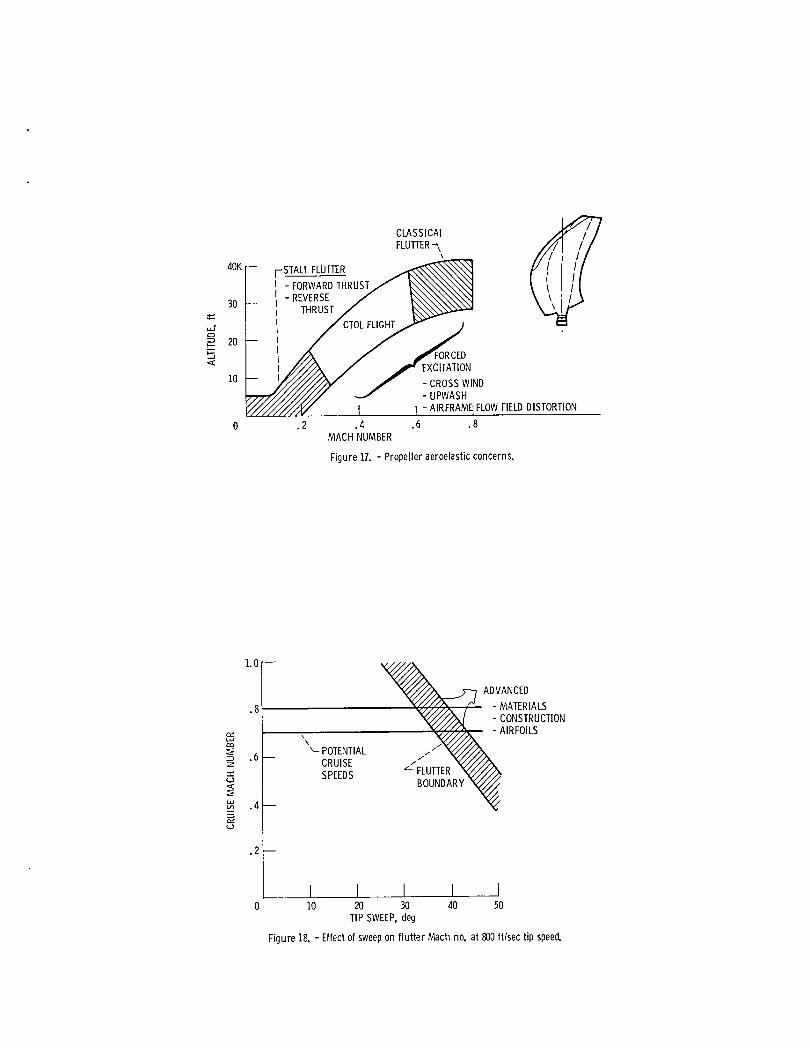
There are three propfan blade aeroelastic concern areas, as
indicated over a typical flight envelope in Fig. 17. Stall
flutter is a cyclic stall-unstall-stall phenomenon that occurs
only at static or low flight speeds. Classical flutter is a
dangerous phenomenon that occurs only at high speeds - beyond
Mach 0.6. Forced excitations occur over the entire flight en-
velope and are caused by unsteady, unsymmetrical airflows pro-
duced by gusts, upwash from the wing, and airframe induced flow
field distortions. Peak forced excitations occur at low speed
climb and high speed cruise conditions. Of particular concern
with swept blades at high flight speeds is the possible onset of
classical flutter. The flutter boundary shown as a function of

16
cruise Mach number and tip sweep in Fig. 18 is not very well
defined. The anticipated flutter boundary is one reason why
the sweep of the SR-7 designed under the LAP contract is being
limited. Although analytic codes are in use to predict the
flutter boundaries of advanced swept blades, the reliability of
these predictions is somewhat questionable because of the dif-
ficulty of structurally modeling the spar/composite shell con-
struction of a full-size blade (see blade sketch in fig. 17)
which is cambered and twisted and flexes under load. Predic-
tion of the type of flow field to be encountered in an actual
installation, especially in terms of unsteady aerodynamic loads
that will be imposed, also complicates the prediction of a flut-
ter boundary. Experimental wind tunnel subscale structural/
aeroelastic modeling is also questionable because of the diffi-
culty of simulating large-scale construction techniques (e.g.,
the minimum gauge problem with the shell) at reduced scale.
Large-scale testing, therefore, is necessary to validate the
structural integrity of these advanced designs.
The propeller technology effort was recently expanded to
include more work related to counter-rotation systems. An
example is the completion by Hamilton Standard of acoustic and
aeroelastic flight tests of the counter-rotation propellers
powering the Fairey-Gannet aircraft. The Fairey-Gannet is shown
in Fig. 19 during acoustic flight tests with the NASA Lewis
Learjet to obtain far-field directivity data. A microphone boom

17
was mounted under the wing of the Fairey-Gannet to obtain near-
field noise data. Subsequent aeroelastic flight tests were com-
pleted in April 1984 with the propeller blades strain gauged to
determine their dynamic response to several different flight
conditions.
Installation Aerodynamics
As early as 1976, concern over the likelihood of severe
adverse interference penalties prompted a NASA wind tunnel in-
vestigation of the effect of a simulated propeller slipstream
ahead of a swept supercritical wing. The results, although
inconclusive, indicated that the effect of the propeller induced
swirl was a major factor in aircraft cruise drag. More recent
wind tunnel tests using a small-scale powered propeller on a
semi-span aircraft model have provided a clearer understanding
of the propeller/slipstream/nacelle/wing interactions. These
tests identified several techniques to better integrate the
propeller and nacelle with the wing_ Use of these techniques
results in drag penalties comparable to those of turbofans. One
technique involving the addition of a wing leading edge exten-
sion (LEX) and fillets (fig. 20), has been simulated in wind
tunnel testing at NASA Ames. Results for an under-the-wing in-
stallation indicate that the installation drag increment due to
the propeller slipstream effects can be eliminated by the LEX
and fillets with the only drag penalty associated with the tur-
boprop being that due to nacelle skin friction. Further im-
provements are expected through nacelle contouring and LEX

18
droop. Efforts to develop and apply analytical methods address-
ing installation effects are also under way. Efforts have also
been initiated to analyze and experimentally investigate aft-
pusher, counter-rotation configurations. Such an arrangement
yields a "clean" wing but introduces new problems involving wake
ingestion through the propeller blades from nacelles and other
upstream aerodynamic surfaces, engine exhaust surrounding the
gearbox and pitch change mechanism, engine exhaust passing
through the propeller blades, and possible aircraft stability
and control problems due to the aft location.
Another vital concern addressed in the NASA installation
investigations is that of inlet and diffuser performance in the
presence of the propeller flow field. The performance of var-
ious types of inlets, some of which are depicted in Fig. 21,
has been experimentally evaluated in joint NASA/industry test
programs with Lockheed-Georgia, Hamilton Standard, United
Technologies Research Center, Boeing, and Pratt & Whitney.
Tests were performed with single-scoop, twin-scoop, and annular
inlets. Trade studies were performed to determine the propeller
inlet area to obtain the optimum balance between external and
internal diffusion losses for maximum pressure recovery and
acceptable distortion at the compressor face. The effect of a
boundary layer diverter on the inlet flow was also investigated,
as was the importance of cowl shape on the external flow field
in the transonic region. In general, the results of these tests
indicate that very good pressure recoveries with acceptable dis-
tortion levels can be achieved with single-scoop inlets of

19
either the shaft penetration or wrap-around type. It was also
found that the addition of a boundary layer diverter of the
proper height significantly improves inlet pressure recovery
and reduces flow distortion at the compressor face. Results
with annular inlets were not as encouraging because of their
shallow height requirement which induces a boundary layer build-
up and resistance to flow. Although the relatively large over-
all height typical of a single-scoop inlet is beneficial to
internal flow, preliminary results indicate that at high flight
speeds there is a danger of high blade stress due to higher
order excitation caused by the proximity of such an inlet.
These blade excitations can be alleviated by increasing the
axial spacing between the propfan and inlet at the expense of
some reduction in pressure recovery.
Cabin Environment
One of the major concerns for any future turboprop airplane
that competes in the marketplace against quiet, smooth riding
turbofan-powered airplanes is the level of cabin noise and vi-
bration. Passenger comfort levels with past turboprops has
been less favorable than with turbofans, and propfans are not
likely to alleviate this negative aspect without substantial
advances in noise reduction technology. Propfan source noise
is expected to be on the order of 145 dB (fig. 22). To achieve
a cabin environment comparable to current turbofan transports
(about 82 dBA) a reduction of 50 to 55 dB is required. This
is about 25 dB beyond the capacity of conventionally treated
fuselage sidewalls.

2O
Langley Research Center has initiated several noise reduc-
tion activities, including the evaluation of advanced sidewall
concepts, precision synchrophasing, active noise suppression,
and the determination of structure-borne (versus airborne) noise
paths. The latter is important because preliminary tests using
a Twin-Otter airplane with a fuselage wrap airborne noise bar-
rier (fig. 23) indicate that substantial levels of acoustic
disturbances arecarried into the cabin via the airplane struc-
ture, thus setting a "noise floor" on the order of i0 dB below
the airborne levels. Thus if _he desired interior noise level
is more than i0 dB below the airborne level, both the airborne
and structure-borne noises will have to be attenuated.
The degree of conventional sidewall attenuation was measured
with a Swearingen Metro fuselage inside a static acoustic test
facility and compared with noise prediction theory as shown in
Fig. 24. While the agreement between theory and experiment is
good at the higher harmonics, the agreement is poor at the more
important fundamental blade passage frequency. These discrep-
ancies are being addressed with more refined analyses that
account for boundary layer refraction, wing diffraction, un-
steady blade loading, and nonlinear sound propagation. These
analyses are being supplemented by high speed acoustic wind
tunnel model tests and flight tests. The high speed flight
tests involved model propellers mounted atop a JetStar (lower
left photo, fig. 24), as mentioned earlier, and provided general

21
agreement between source noise theory and near-field measure-
ment. Far-field measurements also verified that the pressure
disturbances behave as acoustic waves rather than more trouble-
some shock waves.
Drive System
Two elements of the NASA propfan drive system technology
effort are shown in Fig. 25. One of these is the blade pitch
change mechanism. Because the propfan concept involves very
wide chord blades, the twisting moments that must be applied
when changing pitch are considerably greater than for a conven-
tional propeller and therefore require much more actuator force.
Another complication for the pitch change mechanism is intro-
duced by counter-rotation arrangements since twice as many com-
ponents are required. Worse yet, although in-line gearboxes
are preferred for counter-rotation because they are simpler and
lighter than the offset types usually used in single rotation
applications, they limit accessibility to current technology
pitch change mechanisms. Thus, either maintenance costs rise
or alternative pitch change concepts need pursuit. The latter
choice is preferable and is the subject of two on-going NASA-
sponsored studies which show that the pitch change mechanism
can be designed to be autonomous and located in the propeller
hub, whether the gearbox is offset or in-line. This is true
for either single- or counter-rotation applications, although
for C-R maintenance and accessibility is expected to be more
complicated than for S-R and may require the removal of the
first-stage prop.

22
Also in progress is the preliminary design of both single-
rotation and counter-rotation gearboxes to help identify specif-
ic technology requirements. The key problem is the maintenance
and reliability shortcomings experienced in past designs and
the nonexistence of a large turboprop gearbox (e.g., 12 000 to
15 000 SHP). NASA and the engine manufacturers believe that a
large modern gearbox can indeed be constructed that overcomes
the previous shortcomings - largely through the use of sophis-
ticated dynamic system analysis tools and design ingenuity - but
the airplane manufacturers and airlines require hard data before
committing to new concepts. Toward this end NASA is pursuing
advanced gearbox technology in several joint government/industry
endeavors.
LARGE-SCALE PROGRAM
The major focus of the ATP Program at the present time is
the large-scale propulsion system evaluation effort encompass-
ing both a single-rotation wing-mounted tractor configuration
(LAP/PTA) and a unique gearless counter-rotation pusher design
(UDF), as previously discussed in connection with Fig. 9. The
main objectives of the singe-rotation effort are to verify the
structural integrity of the propfan blades and to determine
cabin acoustic characteristics. In addition to these ob-
jectives, the counter-rotation UDF test program also has the
objective of demonstrating the operational feasibility and
aeromechanical performance of the unique direct-drive power
turbine/propeller/exhaust system concept. The approach used in
23
accomplishing these objectives is to design and fabricate large-
scale propeller assemblies for ground test; flight test a
single-rotation, wing-mount, tractor installation on a testbed
aircraft; and, if warranted, flight test a suitable counter-
rotation propulsion system - either the UDF or a geared propfan
design.
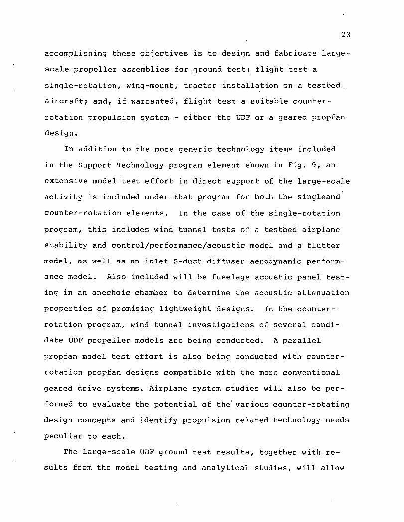
In addition to the more generic technology items included
in the Support Technology program element shown in Fig. 9, an
extensive model test effort in direct support of the large-scale
activity is included under that program for both the singleand
counter-rotation elements. In the case of the single-rotation
program, this includes wind tunnel tests of a testbed airplane
stability and control/performance/acoustic model and a flutter
model, as well as an inlet S-duct diffuser aerodynamic perform-
ance model. Also included will be fuselage acoustic panel test-
ing in an anechoic chamber to determine the acoustic attenuation
properties of promising lightweight designs. In the counter-
rotation program, wind tunnel investigations of several candi-
date UDF propeller models are being conducted. A parallel
propfan model test effort is also being conducted with counter-
rotation propfan designs compatible with the more conventional
geared drive systems. Airplane system studies will also be per-
formed to evaluate the potential of the'various counter-rotating
design concepts and identify propulsion related technology needs
peculiar to each.
The large-scale UDF ground test results, together with re-
sults from the model testing and analytical studies, will allow

24
a comparative evaluation to determine which counter-rotation
system has the most potential and should be pursued further in
a flight test evaluation.
Single-Rotation
The large-scale single-rotation phase of the ATP Program
began in 1981 and initially consisted of (i) testbed aircraft
studies to identify existing airplanes and drive systems that
could be used for in-flight evaluations of large-scale advanced
propfans and (2) blade definition and scaling studies to deter-
mine the characteristics of the large-scale propfan blades to
be built and tested in the subsequent effort. The testbed stud-
ies were done under contracts awarded to Douglas and Lockheed,
both of which concluded that suitable airplanes existed for
such a test and that engines and gearboxes existed that could,
with relatively simple modifications, deliver the power required
by a large-scale propfan at the critical high-speed flight con-
dition. They concluded, furthermore, that a testbed airplane
flight test approach was indeed the most feasible way to vali-
date propfan structural integrity at high-speed flight condi-
tions since ground test facilities which can accommodate a
large-scale propfan and adequately simulate such conditions do
not exist. These airframers also concluded that a flight test?
was the best way to obtain large-scale propfan source noise
data to evaluate acoustic scaling techniques, determinecabin
interior noise levels, and evaluate methods for the attenuation
of such noise.

25
Hamilton Standard was awarded a blade definition and scaling
contract in 1981 to design a large-scale single-rotation prop-
fan to be fabricated and ground tested with facility power in
the subsequent Large-Scale Advanced Propeller (LAP) contract
awarded in mid-1982. The 9-foot diameter SR-7 propfan design
resulting from the LAP program (fig. 26) is a refined version
of the SR-3, having about the same tip sweep but somewhat less
inboard sweep. It incorporates the spar-shell type of construc-
tion illustrated in Fig. 27. All of the Hamilton Standard pro-
pellers for new commuter aircraft use straight blades that
incorporate a similar spar-shell type of construction which has
proven to be very safe, reliable, and lightweight. With this
construction, FOD problems inherent in earlier solid aluminum
blades are avoided by protecting the single load-bearing spar
with an aerodynamically-shaped fiberglass shell. Use of this
construction technique for large-scale propfans avoids the need
to develop new fabrication processes, thereby enhancing the
probability of initial success and industry acceptance, and
appears to be satisfactory, based on design analysis techniques.
This design methodology, however, is unproven for the thin,
swept, composite propfan construction which introduces complex
nonlinear blade deflections and the possibility of high-speed
classical flutter, thereby reinforcing the need for large-scale
testing to verify structural integrity.
In selecting a blade size for the verification of propfan
structural integrity the following three considerations are
apparent:

26
• A size as close as possible to full-size should be
selected to eliminate concerns about further upward
scaling of aeroelastic test data.
• Minimum gauge of the shell used in the spar-shell
construction dictates a blade diameter of at least
eight to nine feet if realistic scaling of the struc-
tural cross-section is to be maintained.
• An engine and gearbox should be available that could,
with minimal modifications, meet the power and rota-
tional speed requirements of the propfan.
Since existing drive system capability is limited to about
3000 SHP at the critical high-speed (Mach 0.8, 35 000 ft. alti-
tude) condition, and disk loadings (SHP/D 2) of 30 to 40 SHP/ft 2
are required, propfan maximum diameters cannot exceed 9 to
i0 feet for a near-term testbed aircraft. The band of possible
propfan diameters established by the aeroelastic scaling and
available power considerations is shown in Fig. 28, together
with a plot of approximate full-size propfan size requirements
as a function of airplane gross weight. This plot shows that a
full-size propfan for a twin-engine installation would have a
diameter of i0 to 18 ft., depending on airplane size. These
considerations dictated the design requirement of a nine-foot-
diameter propfan for the large-scale test program. Structural
and aeroelastic scaling capability from the nine-foot test con-
figuration to even larger sizes are thought to be sufficiently
reliable to warrant this early test with an available drive
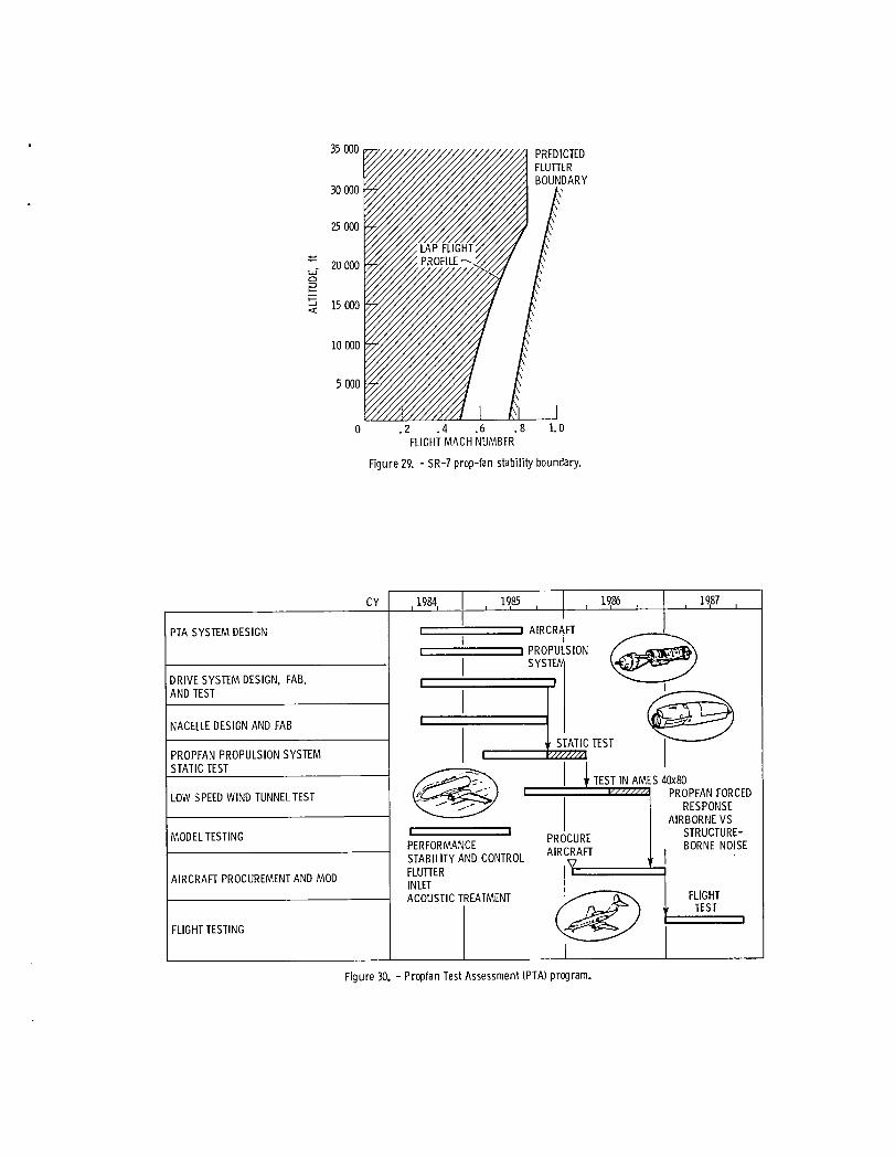
system. Structural analysis performed under the LAP contract
27
predicts that acceptable flutter margin will be obtained over
the projected flight profile for this thin, swept SR-7 blade
design, as indicated in Fig. 29.
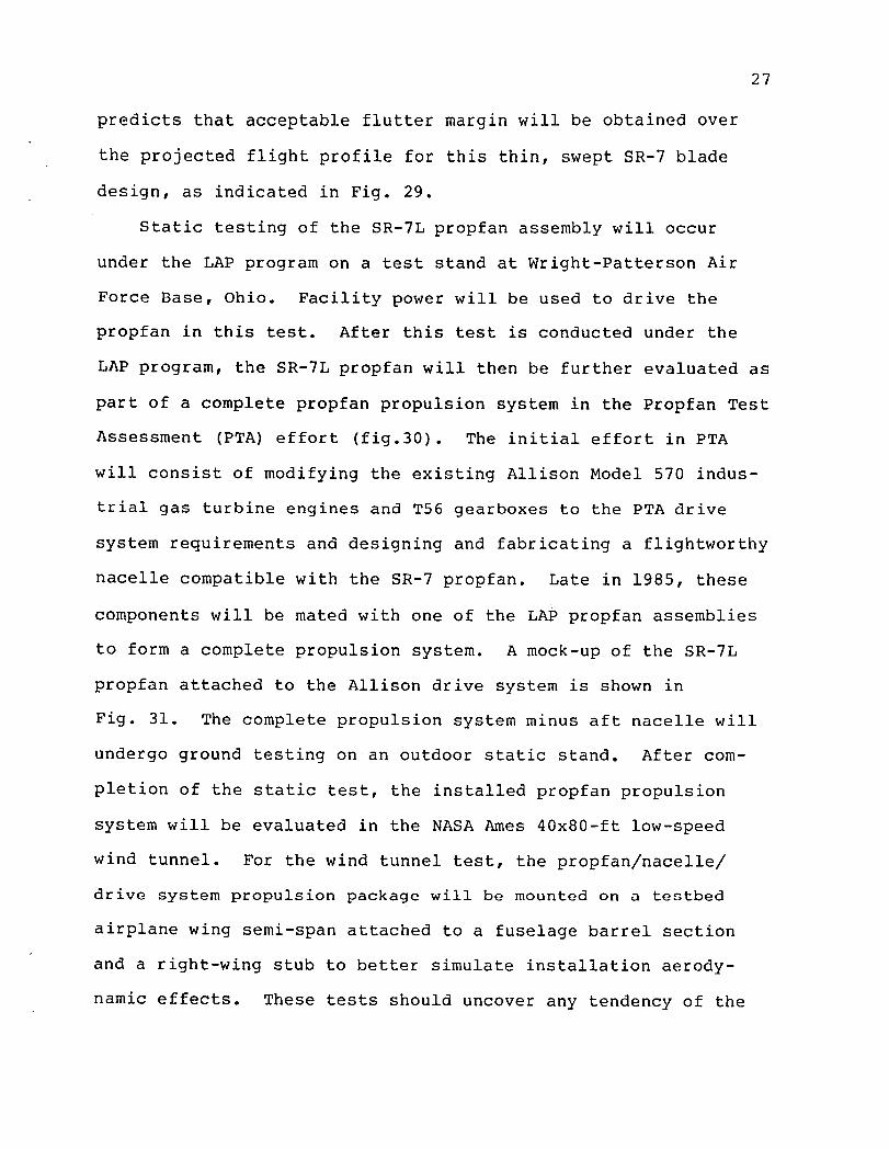
Static testing of the SR-7L propfan assembly will occur
under the LAP program on a test stand at Wright-Patterson Air
Force Base, Ohio. Facility power will be used to drive the
propfan in this test. After this test is conducted under the
LAP program, the SR-7L propfan will then be further evaluated as
part of a complete propfan propulsion system in the Propfan Test
Assessment (PTA) effort (fig.30). The initial effort in PTA
will consist of modifying the existing Allison Model 570 indus-
trial gas turbine engines and T56 gearboxes to the PTA drive
system requirements and designing and fabricating a flightworthy
nacelle compatible with the SR-7 propfan. Late in 1985, these
components will be mated with one of the LAP propfan assemblies
to form a complete propulsion system. A mock-up of the SR-7L
propfan attached to the Allison drive system is shown in
Fig. 31. The complete propulsion system minus aft nacelle will
undergo ground testing on an outdoor static stand. After com-
pletion of the static test, the installed propfan propulsion
system will be evaluated in the NASA Ames 40x80-ft low-speed
wind tunnel. For the wind tunnel test, the propfan/nacelle/
drive system propulsion package will be mounted on a testbed
airplane wing semi-span attached to a fuselage barrel section
and a right-wing stub to better simulate installation aerody-
namic effects. These tests should uncover any tendency of the
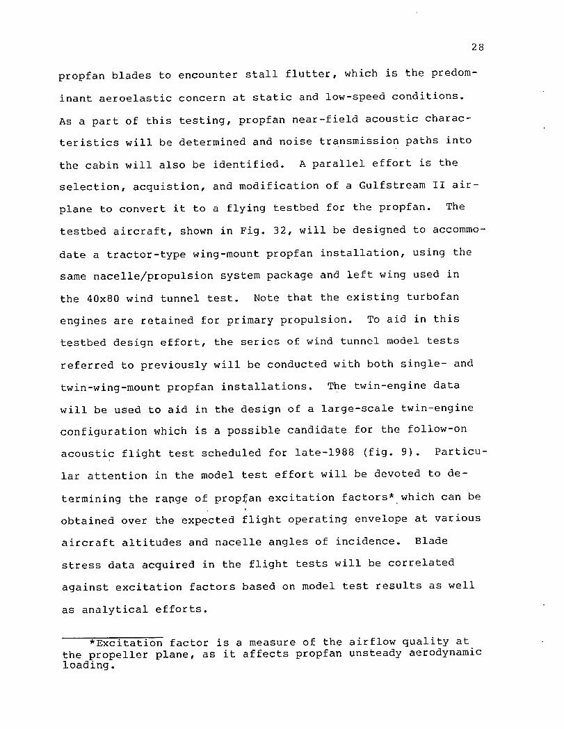
28
propfan blades to encounter stall flutter, which is the predom-
inant aeroelastic concern at static and low-speed conditions.
As a part of this testing, propfan near-field acoustic charac-
teristics will be determined and noise transmission paths into
the cabin will also be identified. A parallel effort is the
selection, acquistion, and modification of a Gulfstream II air-
plane to convert it to a flying testbed for the propfan. The
testbed aircraft, shown in Fig. 32, will be designed to accommo-
date a tractor-type wing-mount propfan installation, using the
same nacelle/propulsion system package and left wing used in
the 40x80 wind tunnel test. Note that the existing turbofan
engines are retained for primary propulsion. To aid in this
testbed design effort, the series of wind tunnel model tests
referred to previously will be conducted with both single- and
twin-wing-mount propfan installations. The twin-engine data
will be used to aid in the design of a large-scale twin-engine
configuration which is a possible candidate for the follow-on
acoustic flight test scheduled for late-1988 (fig. 9). Particu-
lar attention in the model test effort will be devoted to de-
termining the range of propman excitation factors* which can bet
obtained over the expected flight operating envelope at various
aircraft altitudes and nacelle angles of incidence. Blade
stress data acquired in the flight tests will be correlated
against excitation factors based on model test results as well
as analytical efforts.
*Excitation factor is a measure of the airflow quality atthe propeller plane, as it affects propfan unsteady aerodynamicloading.

29
The flight tests are intended to verify the structural suit-
ability of the SR-7 propfan design in the areas of rotor vibra-
tory response and classical blade flutter, and determine the
acoustic characteristics of the propfan as well as cabin inter-
ior noise levels in the vicinity of the propfan plane. Testing
will be conducted over a broad spectrum of flight operating
conditions and will encompass the Mach 0.8/35 000 ft propfan
design condition. Excitation factor will be varied over a range
of values up to the propfan design limit by changing aircraft
angle of attack or incidence angle of the variable tilt nacelle.
Low-speed far-field noise measurements will also be made at
typical takeoff sideline and fly-over conditions as well as
landing approach to obtain an initial indication of noise levels
likely to be encountered in the airport and community environ-
ment. After the completion of the structural integrity/bare
cabin wall acoustic flight tests in 1987 (fig. 9), a series of
follow-on acoustic flight tests is Planned for 1988 with one or
more advanced noise suppression concepts installed within the
cabin walls.
Counter-Rotation
The attractiveness of counter-rotating propeller systems
derives from their ability to reduce the rotational, or "swirl,"
losses associated with single-rotation systems. In order to
generate propulsive thrust, a single-rotation propeller must
take essentially axial flow and turn it in order to do work on
it, in much the same way that an airplane wing must turn the
flow slightly downward in order to generate upward lift. The
30
result with a single-rotation propeller is that the discharge
flow must have a nonaxial rotational component of perhaps
several degrees, depending on disk loading and tip speed. A
decrease in net thrust (and, hence, propulsive efficiency) re-
sults from this nonaxial velocity component since the total
change in momentum is not in the axial direction, as it ideally
should be for the production of thrust. As the disk loading is
increased to minimize the blade diameter and associated weight,
swirl becomes more significant than in older, more conventional
designs. This effect can be reduced by increasing the blade
tip speed, but this has already been done to the extent desir-
able in the SR-7 propfan design, which at 800 ft/sec at the
Mach 0.8/35 000 ft design point is into the transonic region.
Further increases in tip speed will increase the noise level
and begin to reduce efficiency. The swirl losses for an iso-
lated SR-7 propfan at design point operating conditions are
equivalent to about eight points in efficiency. A similar per-
centage reduction in fuel consumption could be obtained by the
elimination of swirl.
Some of the swirl produced by wing-mounted tractor single-
rotation propfan installations can be removed by properly con-
touring the wing leading edge and nacelle. Essentially all of
the swirl can be removed, however, by a properly designed
counter-rotation system such that the swirl imparted by the
front blade is nearly of equal and opposite direction to that
produced by the second set of blades. With a counter-rotation
system, additional installation flexibility is available since

31
there is no dependence on other aerodynamic surfaces to remove
swirl. Aft-type pusher installations then become feasible from
a propulsive efficiency standpoint, whereas with a single-
rotation pusher propfan such an aft-mount location might not be
attractive because of the lack of potential for swirl recovery.
Aft-mounting may be attractive from a cabin noise point-of-view,
however, since it places the noise source aft of the aft fuse-
lage bulkhead. It also would allow a cleaner, more uncluttered
wing with possibly better lift-drag characteristics.
The major focus of the large-scale counter-rotation effort
at the present time is the design, fabrication, and ground test
of the pusher-type gearless UnDucted Fan (UDF) propulsion sys-
tem, which is shown in the cutaway drawing of Fig. 33. As shown
in the schedule of Fig. 9, work on the UDF began in FY 84 and
will continue through CY 1986 when the ground test effort will
be completed. This new engine concept is being developed by
General Electric under a cost sharing contract with NASA. It
features an aerodynamically coupled gas generator and counter-
rotating power turbine, the latter of which converts the gas
generator engine power to that required by the directly-driven
propfan without the requirement for the development of a new
gearbox or provision for additional shafting. The 20 000-hp-
class demonstrator propulsion system uses an F404 turbofan
engine (with the augmentor removed) as the gas generator ahead
of the "propulsor" unit which contains the turbine rotors, power
frames, prop blades, and turbine static structures. The F404 is
a fully-developed low-bypass turbofan engine which is used in

32
the Navy F-18 fighter. Attention in this program, therefore,
will be more properly concentrated on developing the propulsor
unit. The propuls0r prop blades will be designed for a high
overall disk loading of approximately 50 SHP/D 2 at the high-
speed cruise point, and for high hub-to-tip radius ratios of
about 0.4, whereas more conventional designs have hub-to-tip
ratios of 0.15 to 0.25. This high radius ratio is necessitated
by the large diameter of the power turbine, which in turn is
dictated by the low rotational speed set by the propfan tip
speed limitation of approximately 800 ft/sec. The low rota-
tional speed of the power turbine and the power requirement of
the 12 ft diameter propeller blades also dictate that 12
counter-rotating stages be included in the power turbine design.
Another unique feature of this turbine design is that, except
for a set of inlet and outlet guide vanes, there are no stator
vanes between the alternating opposite rotation blade rows.
The development of the large-scale UDF propulsion system is
supported by an extensive NASA-sponsored model program to verify
the aerodynamic and aeroelastic performance and determine the
aeroacoustic characteristics of the counter-rotating prop
blades. In addition to these model tests, numerous component
tests will be conducted prior to the full engine ground test
program which will start in 1985. These tests will verify the
mechanical design and functional integrity of the major UDF
propulsor components, including the power turbine, prop blades,
and static structure.
33
The ground test of the complete UDF engine will be con-
ducted on an outdoor test stand and will provide a data base
for engine performance, operability, durability, and acoustic
characteristics. The results of the ground test will be used
in the comparative evaluation of the UDF concept against other
more conventional counter-rotation propfan designs and will
serve as a data base which could be used in a possible follow-on
flight test evaluation.
As the schedule chart of Fig. 9 shows, NASA is conducting a
parallel counter-rotating propfan effort of more conventional
designs with a lower hub-to-tip radius ratio, drawing more ex-
tensively on experience gained in the single-rotation experi-
mental and analytical effort. These counter-rotational propfan
models will be designed, fabricated, and tested under contract
by Hamilton Standard. They will be wind tunnel tested on a
propeller test rig and evaluated to determine their aerodynamic
performance, as well as their acoustic and aeroelastic charac-
teristics. Parallel with this, counter-rotation gearbox tech-
nology, as previously discussed in connection with Support
Technology, will be accelerated under contracts with Pratt &
Whitney and Allison. A geared counter-rotation propfan propul-
sion system data base will thus be established to aid in the
selection of a system for a possible counter-rotation flight
test. In the event that the geared propfan system is selected
for the flight test configuration, a counter-rotation counter-
part to the single-rotation LAP program would be implemented
34
prior to the flight evaluation to build and assemble the re-
quired propulsion system hardware.
CONCLUDING REMARKS
Studies and model tests indicate that thin, swept, highly-
loaded turboprops applied to high-speed (Mach 0.65 to 0.85)
commercial aircraft can produce block fuel savings of 15 to 30
percent relative to advanced turbofans (50 to 60 percent rela-
tive to today's turbofan fleet). With fuel prices at around
$1/gal, over 50 percent of the DOC is accounted for by fuel.
The fuel savings predicted for advanced turboprop-powered air-
craft translates into a 7 to 15 percent reduction in DOC com-
pared to that possible with advanced turbofans. Such fuel
savings potential could have considerable impact on airline
profits. For instance, a 20 percent fuel savings, which is
perhaps a conservative estimate for a wing-mount single-rotation
propfan in a tractor-type installation, could have eliminated
the $441 million U.S. airline deficit incurred in 1981 and
caused a substantial profit to be realized if applied only to
the Boeing 727 part of the domestic fleet. The market potential
for short/medium range aircraft with such fuel savings capa-
bility is huge. If we could initiate production of these air-
craft in the early 1990's, it is estimated that by the year
2000 they could produce a 350 billion favorable trade balance
for the U.S. Delays in acquisition and implementation of the
technologies required to realize this potential fuel savings,
35
however, could jeopardize our head start in this effort and
allow foreign competition to erode the apparent United States
advantage.
The planned NASA program calls for the flight test of a
large-scale single-rotation propfan in 1987 to verify its struc-
tural integrity and characterize near-field source noise, as
well as to identify acoustic_transmission paths into the cabin.
The aerodynamic performance advantages of single-rotation prop-
fans have already been verified in tests of small-scale models.
Structural integrity and acoustic characteristics, however,
cannot be as easily verified at small scale, thereby providing
the impetus for the large-scale flight test effort.
A follow-on acoustic flight test is also planned for 1988
to determine the effect of advanced acoustic treatment on cabin
interior noise and to demonstrate that cabin noise levels simi-
lar to those achieved with today's turbofans can be obtained.
An effort is also being initiated to achieve technology readi-
ness in gearboxes, for both single- and counter-rotation
designs. This effort is needed for two reasons: (i) gearboxes
are not currently available in the 12 000 to 15 000 SHP size
that will be required in commercial airline applications, and
(2) maintenance and reliability shortcomings have been experi-
enced in the past with gearboxes designed for lower power
levels.
Because of their relative simplicity, the NASA program until
this year had concentrated on validating the technologies di-
rectly applicable to single-rotation propfans, as opposed to
36
counter-rotation designs. This year, however, a significant
joint effort was initiated with General Electric to ground test
a large-scale gearless counter-rotation turboprop propulsion
system (the UDF). Counter-rotation is attractive because, if
properly designed, it can eliminate the swirl losses associated
with an uninstalled single-rotation propeller. (Some of these
losses in an uninstalled single-rotation propfan can be re-
covered in _ wing-mount tractor installation, however, by prop-
erly contouring the portion of the wing and nacelle inside the
prop wash.) Additional effort is being applied under a model
test contract to Hamilton Standard to better understand the
aerodynamic performance of more conventional counter-rotation
propfans compatible with geared drive systems. These tests,
together with parallel analytical studies and airplane mission
comparisons, will allow a decision to be made late in 1987 to
determine which counter-rotation system warrants pursuit through
the flight test phase. The purpose of such a test would be to
bring counter-rotation technology to the same state of readiness
as that of single-rotation after the PTA flight test of the
single-rotation propfan. Upon completion of the NASA program
toward the end of the decade, the airframe and propulsion indus-
try will then have available the technology base required to
make a marketing decision regarding the design of possible pro-
totype aircraft, applying whichever technologies appear to be
most appropriate for the chosen configuration.

37
With fuel conservation such a major concern today, and with
the potential operating cost savings attributable to the ad-
vanced turboprop, it behooves us to advance this technology
effort as rapidly as possible to enable the aeronautical com-
munity and the public at large to share in these potential
benefits.


Figure1. - Routeto improvedfuel efficiency.
90LLJ(.3
_-_ r-POTENTIALIMPROVEMENTS
>= 80 SINGLEROTATION,,z, SWIRLRECOVERY
_ ADVANCEDAIRFOILS
ELECTRA-' COUNTER-ROTATION__ 70 SINGLEROTATIONWIND
HIGHBYPASS TUNNELTESTSa_
a. 60--
50 I ! I I- .5 .6 .7 .8 .9
FLIGHTMACHNUMBER
' Figure2. - Comparisonof propfanandturbofanpropulsiveefficiencies.
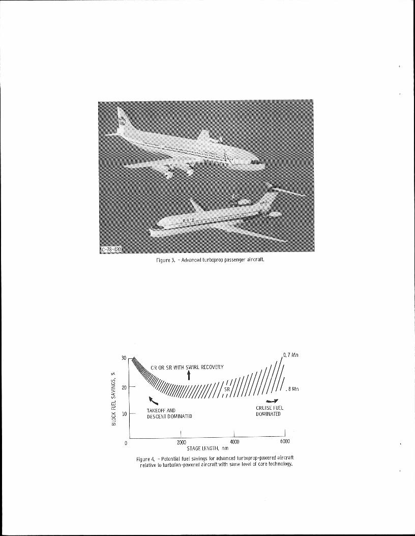
Figure3. - Advancedturboproppassengeraircraft.
30 O.1Mn
CRORSRWITHSWIRLRECOVERY
m-
z 20 8 Mn
'_' TAKEOFFAND CRUISEFUELlO -- DESCENTDOMINATED DOMINATED
o_,
I I I0 2000 4000 6000
STAGELENGTH,nm
Figure4. - Potentialfuel savingsfor advancedturboprop-poweredaircraftrelativetoturbofan-poweredaircraft with samelevelof coretechnology.
20%FUELSAVINGS
f _~$ 500,000PERB731NC PERYEAR U.S.CAPTURESMARKETOF
-2000NEW SHORT/MEDIUMRANGEA/CBYYEAR2000
$ 1.1 BILLIONANNUALLY $ 50BILLIONFAVORABLETRADEFORSHORTIMEDIUMRANGE BALANCEU. S. AIRPLANEFLEET
1000--
$664M
< "_ _ F IF20'=I.FUEL._- 500-- 737..................
____ _ / SAVINGSHAD
_-__ / OCCURREDIN< PORTIONOF_ 0 i FLEET
U 1( 2000NEWSHORT/MEDIUM-500_ $441M RANGEAIRCRAFT
Figure5. - ATPtechnologybenefits.
OBJECTIVE ESTABLISHSRANDCRPROPFANTECHNOLOGY
FORMACH0.6.5-0.85APPLICATIONS
PROGRAMBENEFITSIGOALS _:-"
FUELSAVINGSOVERCOMPARABLETURBOFANS
7-15%,
DOCSAV,NGSOVERCOMPARABLETURBOFANS_ _
SAFEANDRELIABLESYSTEM
CABINNOISE/VIBRATIONSIMILARTOTURBOFAN'S t _--"_'_
MEETFAR36-111COMMUNITYNOISEREGS
TECHNOLOGYREADINESSBY LATE1980'S _'__
Figure6. - AdvancedTurbopropProgramobjective,benefitsandgoals.

<__ AIRCRAFTTRADEOFFS
DRIVESYSTEM P LE
PROPPITCHCHANGE •GEARBOXESINLETS • STRUCTURES
PUSHERENGINES_ _I_ __
INSTALLATION GOALS _._\\_AERODYNAMICS • LOW FUELCONSUMPTION NOISEAND VIBRATION
• DRAG • LOW OPERATINGCOST • PASSENGERNOISE• PASSENGERACCEPTANCE • COMMUNITYNOISE• STABILITYCONTROL
Figure7o-Elementsneededforthedevelopmentofadvancedturbopropaircraft.
PROJECTMANAGEMENT
IHEADQUARTERSII
I PROJEcTLEWISoFFICEI PR°JEcTMANAGEMENT'c°°RDINATI°N
IAME_I IDRYDENI ILANG_YI I_w,sIINSTALLATIONAERO JETSTARFLTTESTS FUSELAGEACOUSTICS PROPELLERDESIGNAICSTABILITY INSTALLATIONAERO AERODYNAMICS
NC STABILITY ACOUSTICSCONFIGURATION AEROELASTICS
INTEGRATION STRUCTURESINLETINACELLESHAFTENGINETECH.MAJORCONTRACTS
LARGEPROPELLERTESTBEDA/CUNIQUECRENGINE
Y
WORKCONDUCTEDBYCOMBINEDIN-HOUSE,CONTRACTANDGRANTEFFORTS
Figure8, - NASAorganizationscontributingto the advancedturbopropprogram.

FYI 831 84185 186 I 87188 1 _9190ISRAND CRPROP-FANTECHNOLOGYREADINESS
LARGE-SCALEADV.PROPELLER(LAP) 9'_L
SR _J"
ASSESSMENT (PTA)
STRUCT.INTEG. ACOUSTIC
FLIGHTGEARLESS
f 1 UDFMODELDATABASE l
UDFGEARLESSPOWERPLANT I iI_.LAP A
CR_ GEARED CRENGINE/FLIGHT
STUDIES
O ON
/xDECISIONON CRFLIGHT
SUPPORT 1 I I GEARBOXTECHNOLOGY ]
TECHNOLOGY • BLADEAERO,ACOUSTICS,AEROELASTICITY• INSTALL,AERO,INLETS,NOZZLES• CABINNOISEAND VIBRATION
Figure9.-ATPprogramplan.
8 BLADES,0° SWEEP 10BLADES,400SWEEP
8BLADES,450SWEEP
8BLADES,30oSWEEP 10BLADES,O0° SWEEP
C-81-3151Figure10.-PropellermodelsinstalledintheLewisB-by-6footwindtunnel.

Figure11. - Advancedpropellerblades.
Figure12. - Far-fieldacousticflight tests.

CRUISEEFFICIENCY NEARFIELDSOURCENOISE(SPLATBPF)
M:O. 7•80-- 30SHPID2 M=O.8
_ 37.SSHPID2 SR-_,..,. MACHNO. l-.<. SR-3 12dB
/ _ 0.7_ o
7
.76 SR-2
I i i I i iO 20 40 60 O 20 40 60
AERODYNAMICTIPSWEEP,deg
Figure13.-Effectofbladesweeponpropellerpropulsiveefficiencyandnoiseat800fllsectipspeed.
CRUISEEFFICIENCY NEARFIELDNOISE(SPLATBPF)
MACHNO.
.8
7
MACH8 2dB NO.
8% 0.8
I I I I °'z Io 20 40 6o o 20 40 60
TIPSWEEP.deg
Figure14. - Effectof bladethicknesson efficiencyandnoiseat 800ftisectip speed.

BLADETHINNESSCURRENTTECHNOLOGY
ADVANCEDTECHNOLOGY
20-- _ SWEEPI_ THINNESS _'////_
_" _ SAVINGSRELATIVETO
CURRENTTECHNOLOGYI0 -- _ THINNESSANDZERO
SWEEP,-H2
0MACHO.7 MACHO.8
Figure15. - Effectof bladesweepandthinnesson fueldavingsat Mach0.7 andMach0.8.
2.0 m
=
=_.
STRESS IfLIMIT
FIRSTORDERAPPROXIMATION"7 J •
>- 1.5--
IIAII
I,D
1.O II0 20 30 40 50
TIPSWEEP,X, dN
Figure16.- Effectof sweeponsteadystressfor constantgeometryand materials.
CLASSICALFLUTfER_\
\ i I
40K I-STALLFLUTTER /I - FORWARDTHRUSTI
u _ REVERSE30._ I THRUST
I
I,.u- I
20 I,_, I CED
10 - CROSSWIND- UPWASH
I - AIRFRAME{FLOWFIELDDISTORTIONIO .2 .4 .6 .8
MACHNUMBER
Figure11. - Propelleraeroelasticconcerns.
1.0-
ADVANCED
• 8 - MATERIALS- CONSTRUCTION
"x - AIRFOILS
_-POTENTIAL /J.6 -- CRUISE-_ SPEEDS
(J_:_<.4-- BOUNDARY
_J
.2 --
I I I I IO 10 20 30 40 50
TIPSWEEP,deg
Figure18.- Effectof sweepon flutter Machno.at 800ft/sectip speed°

Figure19. - FaireyGannet(CRprop)andLearjetin flight.
Figure20. - Propellerandwing modelshowingleadingedgeextension(LEX)andfillets.

SINGLESCOOP TWINSCOOP
WITHBOUNDARYLAYER WITHOUTBOUNDARYLAYERDIVERTER DIVERTER
SHAFTPENETRATION WRAPAROUND
Figure21. - Inlets investigatedfor theAdvancedTurbopropProgram,
• SUPERSONICSPEEDATPROPELLERTIP
• HIGHEXTERIORNOISELEVELONFUSELAGE
• ADVANCEDFUSELAGETREATMENTREQUIREDFORPASSENGERACCEPTANCE
160I
SOUND1401_
PRESSURE120LEVEL, I 25_
dB lOOl (Ig80= _-_EXTERIORCURRENTGOAL
TREATMENTi J
INTERIOR
PROPOSEDQUIETPROPFAN
Figure22. - Depictionof the highspeedturbopropinterior noiseproblem.
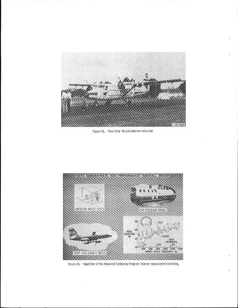
Figure23.- TwinOtter structurebornenoisetest.
Figure24. - Depictionofthe AdvancedTurbopropPrograminterior noisecontrolactivities.

ADVANCEDPITCHCHANGEMECHANISM ADVANCEDSRANDCRGEARBOXESHIGHLOADS RELIABILITYIMAINTAINABILITYCOUNTERROTATIONCOMPLEXITY DESIGNINGENUITY
,,,.d_ . J
SR CR
Figure25.- Elementsofthe propfandrivesystemtechnologyeffort.
Figure 26. - Large-scale advancedpropeller (LAP).

FILL_\ SPAR_ r SHELL/ /\ / /\ / /
ICEPROTECTION-,\
FEROSION
_.....__.._,_._./ PROTECTION_..-_-._, .....--...x_._ ,rLIGHTNING
" PROTECTION
Figure21. - Schematicof the spar-shellbladeconstructionconceptusedfor theLAP.
APPROXIMATE2-ENGINE
20-- AIRPLANE
o TURBOFANEQUIV. REQUIREMENTS_""'Kn"_lSl
• PROPFANSTUDIES __..:i:':':':'::':':'"15-- STUDIE_Io0
"-'_ _D C9-80
_,/_-I00 z-LARGESTENGINE/
O /
ZAPPRO)_MIN.SIZETORETAIN5 -- STRUCTURALSIMILARITYWITH
FULL-SIZEPROPS
I I I I I0 50000 100000 150000 200000 ?_0000
AIRPLANEGROSSWEIGHT,Ib
Figure28. - Sizingof large-scaleprop-fantesthardware.
3500O PREDICTEDFLUTTERBOUNDARY
30000
25000
20OOO
_' 15000
10000
5000
I0 .2 .4 .6 .8 1.0
FLIGHTMACH NUMBER
Figure29.-SR-7prop-fanstabilityboundary.
cY 19_, I , _9,a, , 19,___ , 19,87,PTASYSTEMDESIGN I I AIRCRAFT/
I ] PROPULSION //"__'_SYSTE(V
DRIVESYSTEMDESIGN,FAB, I I
AND TEST I
NACELLEDESIGNANDFAB I.
STATICTESTPROPFANPROPULSIONSYSTEM I v//////A
STATICTEST _ I TESTINAMES40x80
l v//////, PROPFANFORCEDLOW SPEEDWINDTUNNELTEST
I RESPONSEAIRBORNEVS
MODELTESTING , i PROCURE STRUCTURE-PERFORMANCE BORNENOISEAIRCRAFT
STABILITYAND CONTROL '£"7
AIRCRAFTPROCUREMENTANDMOD FLUTTER iINLETACOUSTICTREATMENT FLIGHT
TESTI
FLIGHTTESTING
IFigure 30. - PropfanTest Assessment IPTA)program.

Figure31.- SR-7LpropfanandAllison drivesystem.
Figure32. - GulfstreamII, with profan,to beusedfor flight testsduring the PropfanTestAssessment(PTA)program.

Figure33. - Unductedfanengine(UDF),


1. Report No, 2. Government Accession No. 3. Reczpmnt's Catalog No,
NASATM-837364. Title and Subtitle ,5.Report Date
Fuel Savings Potential of the NASAAdvanced TurbopropProgram 6. Pedormmg Organization CoOe
535-03-12
7. Author(s) 8. Performing Organization Report No,
J. B. Whitlow, Jr. and G. K. Sievers E-221810. Work Unit No.
g. Performing Organization Name and Address
Nati onal Aeronautics and Space Admini strati on 1_.Contractor GrantNo.Lewis Research Center
C1eveland, 0hi o 44135 13. Type of Report and Period Covered
12. Sponsoring Agency Name and Address Techni ca l Memoran dumNational Aeronautics and Space AdministrationWashington, D.C. 20546 t4 Sponsor,ngAgencyCo_e
1'5.Supplementary Notes
Prepared for the Aviation Fuel Conservation Symposium sponsored by the FederalAviation Administration, Washington, D.C., September I0-II, 1984.
16. Abstract
The NASAAdvanced Turboprop (ATP) Program is directed at developing new technologyfor highly-loaded, multi-bladed proppllgrs for use at Mach 0.65 to 0.85 and ataltitudes compatible with the air transport system requirements. Advanced turbo-prop engines offer the potential of 15 to 30 percent savings in aircraft blockfuel relative to advanced turbofan engines (50 to 60 percent savings over today'sturbofan fleet). The concept, propulsive efficiency gains, block fuel savings andother benefits, and the program objectives through a systems approach aredescribed. Current program status and major°accomplishments in both single-rotation and counter-rotation propeller technology are addressed. The overallprogram from scale model wind tunnel tests to large-scale flight tests on testbedaircraft is discussed.
17. Key Wo4"da(Suggested by Autllo,"(s)) 18. Distribution Statfment
Turboprop Unclassified- unlimitedPropeller STARCategory 07Commercial aircraft "Fuel conservation
_19.Se(:urlty Clustf. (of this _) 20. _udty Cluelf. (of this page) 21. No. of page,, 22. Price" '
Unclassi fled Unclassified
"For salebytheNationalTechnicalInformationService,Springfield,Virginia22161


tt2LANGLEYRESEARCHCENTER
,
National Aeronauticsand SPECIAL FOURTH CLASS MAIL 88 L"_
SpaceAdministration Book " 3 1176 00512 72-,_ 1-111171
Washington, D.C. _-i...20546
Official Business
Penalty for Private Use, $300 Postage and Fees PaidNational Aeronautics and
Space AdministrationNASA-451
I
IDO NOT REMOVE SLIP FROM MATERIAL
DeleteyournamefromthisslipwhenreturningmaterialIf Undeliverable (Secli,)n I 5_
NAME Postal Manual) I)_ Not Return-------- MS
j-.
NASA Langley (Rev.May 1988) RIAD N-75