Embed Size (px)
Citation preview

The contents of this document may be subject to change without notice.Sections highlighted in gray (blue in pdf files) are currently still under development.
R
CNT-NXT-12.0E
Fuji Scalable Placement PlatformNXT
Machine Specifications

Points of Caution• The official model name of this machine is NXT. This name should always be used on the
associated documentation when shipping a unit or units of this model to a third country.
• Since this equipment contains strategic materials that are covered by international treaty, it is necessary to obtain government permission to export it to a third country.
• Abbreviated versions of the official model name may appear in this and other related documents.
• Part names are given in millimeters throughout this document, although the equivalent name in inches is given in parenthesis for certain components, e.g. 0603 (0201).
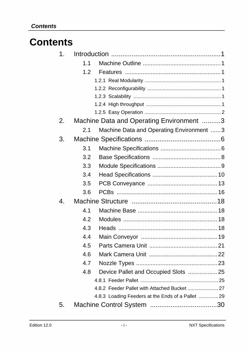
Contents
Edition 12.0 - i - NXT Specifications
Contents1. Introduction ...........................................................1
1.1 Machine Outline ................................................ 11.2 Features ........................................................... 1
1.2.1 Real Modularity ....................................................... 11.2.2 Reconfigurability ..................................................... 11.2.3 Scalability ............................................................... 11.2.4 High throughput ...................................................... 11.2.5 Easy Operation ....................................................... 2
2. Machine Data and Operating Environment ..........32.1 Machine Data and Operating Environment ...... 3
3. Machine Specifications .........................................63.1 Machine Specifications ..................................... 63.2 Base Specifications .......................................... 83.3 Module Specifications ....................................... 93.4 Head Specifications ........................................ 103.5 PCB Conveyance ........................................... 133.6 PCBs .............................................................. 16
4. Machine Structure ..............................................184.1 Machine Base ................................................. 184.2 Modules .......................................................... 184.3 Heads ............................................................. 184.4 Main Conveyor ............................................... 194.5 Parts Camera Unit .......................................... 214.6 Mark Camera Unit .......................................... 224.7 Nozzle Types .................................................. 234.8 Device Pallet and Occupied Slots .................. 25
4.8.1 Feeder Pallet ........................................................ 254.8.2 Feeder Pallet with Attached Bucket ...................... 274.8.3 Loading Feeders at the Ends of a Pallet .............. 29
5. Machine Control System ....................................30
Contents
Edition 12.0 - ii - NXT Specifications
5.1 Machine Control Specifications ...................... 305.2 Operating Environment ................................... 31
6. Standard Functionality ........................................326.1 Pick-up Position Detection .............................. 326.2 Paired Production Mode (M3 (S) module) ...... 326.3 Nozzle Station ................................................ 326.4 Z0 Sensor ....................................................... 326.5 Auto Calibration .............................................. 336.6 Placing Pressure Control ................................ 336.7 Pressure Insertion Placement ........................ 33
7. Options ...............................................................347.1 Options ........................................................... 347.2 Tray Specifications for Tray Unit-L ................. 397.3 Tray Specifications for Tray Unit-M and
Tray Feeder-L ................................................... 417.4 Stick Feeder Specifications ............................ 42
8. NXT Related Software ........................................448.1 NXT Accessory Software ................................ 448.2 Fujitrax ............................................................ 448.3 Fuji Flexa ........................................................ 46
9. Module Configuration .........................................479.1 Module Configuration ..................................... 47
9.1.1 M3 (S) Module Configuration ................................ 479.1.2 M6 (S) Module Configuration ................................ 48
10. Peripheral Equipment .......................................4910.1 Peripheral Equipment ................................... 49
10.1.1 Conveyors .......................................................... 49
11. Machine Illustrations .........................................5011.1 Machine Dimensions .................................... 50
11.1.1 Machine Dimensions (without MTU-L) ............... 5011.1.2 Machine Dimensions (with MTU-L) .................... 51
Contents
Edition 12.0 - iii - NXT Specifications
11.2 Leveling Positions ......................................... 5211.3 Air and Power Supply Locations ................... 5311.4 2M Base Control Box and
Additional Vacuum Pump Box .......................... 54
1. Introduction
Edition 12.0 - 1 - NXT Specifications
1. Introduction1.1 Machine Outline
The NXT is not simply a placing machine, but is the result of Fuji’s endeavor to provide a revolutionary new SMT line concept system, providing a total solution for the requirements of the next generation, today. By incorporating unique technology to enable the machine to automatically adapt to high-mix, variable volume production, and extensive use of sensors to achieve reliable placement and quality management, this new machine represents innovation at the highest possible level.Incorporating a flexible, two-type (M3 (S) and M6 (S)) modular configuration, combined with a thorough effort to reduce both the size and cost of the machine to an absolute minimum has resulted in a more cost effective, more efficient machine with a greatly reduced footprint in comparison to previous generation machines.
1.2 Features1.2.1 Real Modularity
There are 2 module sizes: the M3(S) and M6(S). The NXT has many configurable items including seven head types, pallets for reel and stick feeders, and units and feeders for supplying tray parts. Users can create the best machine configuration for any type of production because they can freely combine module size, head type and device type.
1.2.2 ReconfigurabilityHeads can be easily removed and installed. The machine specifications can be easily adapted to meet changes in production volume and part type. Furthermore, the machine automatically performs calibration after head and unit exchange. Users can freely arrange machine specifications without the need for troublesome settings and adjustments by operators and engineers.
1.2.3 ScalabilityThe number of modules can be adjusted by moving 2 M3(S) modules or 1 M6(S) module to reduce costs and save space. Furthermore, various types of production can be supported simply by exchanging the head. The highly expandable NXT can easily adapt to future changes.
1.2.4 High throughputIt goes without saying that the modular configuration of the NXT results in high productivity in a compact space. The NXT also is incorporates various functions for "non-stop" production.
• Both reel and tray parts can be supplied without stopping the machine.
• When combined with Fujitrax (an optional production management system), the machine can warn operators that parts will run out soon. Operators can then prepare more parts before the original parts run out.
• The following functions reduce changeover time: batch feeder exchange, automatic changeover of back-up pins, automatic adjustment of conveyor width.
1. Introduction
Edition 12.0 - 2 - NXT Specifications
Multijob Line Balancer (optional software in Fuji Flexa) analyzes multiple jobs and determines the device allocation and production order for the most efficient changeover.
• A double conveyor configuration can reduce panel conveyance time to zero.
• Production programs can be changed from the first module in a line in sets of 2 M3(S) modules (or 1 M6(S) module), which results in a seamless changeover flow from the current production to the next production program.
1.2.5 Easy OperationThe graphical interface of the NXT allows operators to intuitively grasp what operation should be performed next, which considerably reduces operator-training time. The NXT operation system combines the ability to operate multiple modules as one machine yet operate modules individually during maintenance.
2. Machine Data and Operating Environment
Edition 12.0 - 3 - NXT Specifications
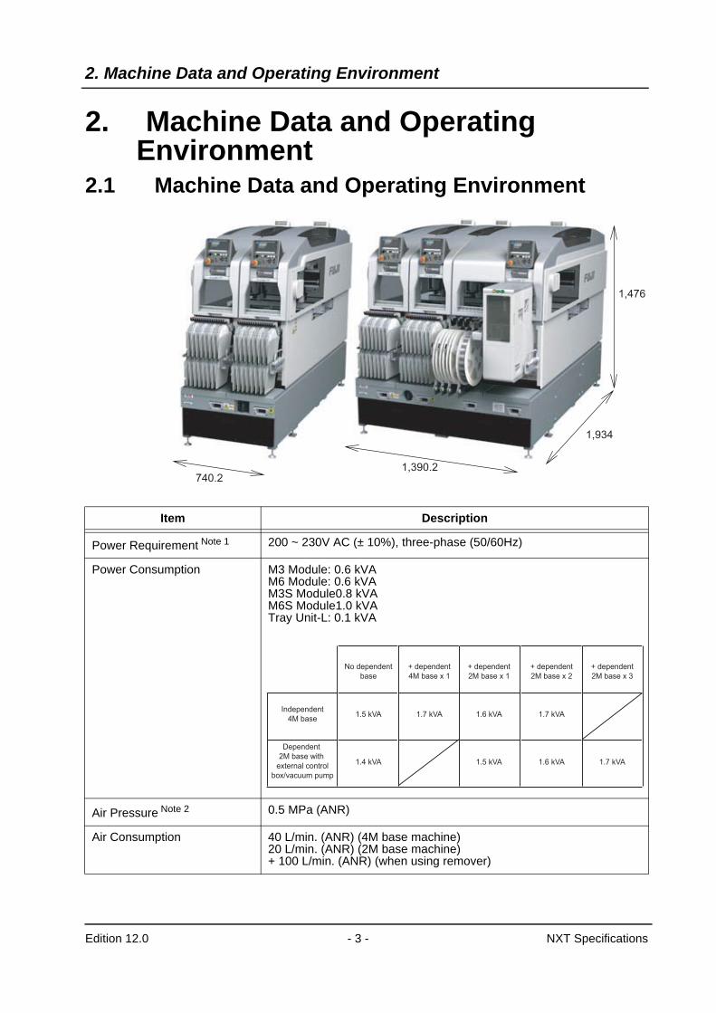
2. Machine Data and Operating Environment
2.1 Machine Data and Operating Environment
740.2
1,934
1,476
1,390.2
Item Description
Power Requirement Note 1 200 ~ 230V AC (± 10%), three-phase (50/60Hz)
Power Consumption M3 Module: 0.6 kVAM6 Module: 0.6 kVAM3S Module0.8 kVAM6S Module1.0 kVATray Unit-L: 0.1 kVA
Air Pressure Note 2 0.5 MPa (ANR)
Air Consumption 40 L/min. (ANR) (4M base machine)20 L/min. (ANR) (2M base machine)+ 100 L/min. (ANR) (when using remover)
Independent
4M base
Dependent
2M base with
external control
box/vacuum pump
No dependent
base
1.5 kVA
1.4 kVA
+ dependent
4M base x 1
1.7 kVA
+ dependent
2M base x 1
1.6 kVA
1.5 kVA
+ dependent
2M base x 2
1.7 kVA
1.6 kVA
+ dependent
2M base x 3
1.7 kVA
2. Machine Data and Operating Environment
Edition 12.0 - 4 - NXT Specifications
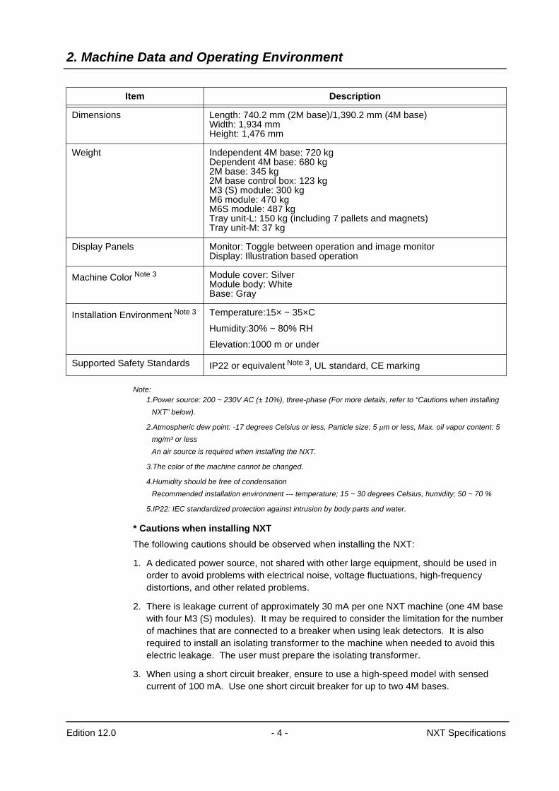
Note:1.Power source: 200 ~ 230V AC (± 10%), three-phase (For more details, refer to “Cautions when installing
NXT” below).
2.Atmospheric dew point: -17 degrees Celsius or less, Particle size: 5 µm or less, Max. oil vapor content: 5 mg/m³ or lessAn air source is required when installing the NXT.
3.The color of the machine cannot be changed.
4.Humidity should be free of condensationRecommended installation environment --- temperature; 15 ~ 30 degrees Celsius, humidity; 50 ~ 70 %
5.IP22: IEC standardized protection against intrusion by body parts and water.
* Cautions when installing NXTThe following cautions should be observed when installing the NXT:
1. A dedicated power source, not shared with other large equipment, should be used in order to avoid problems with electrical noise, voltage fluctuations, high-frequency distortions, and other related problems.
2. There is leakage current of approximately 30 mA per one NXT machine (one 4M base with four M3 (S) modules). It may be required to consider the limitation for the number of machines that are connected to a breaker when using leak detectors. It is also required to install an isolating transformer to the machine when needed to avoid this electric leakage. The user must prepare the isolating transformer.
3. When using a short circuit breaker, ensure to use a high-speed model with sensed current of 100 mA. Use one short circuit breaker for up to two 4M bases.
Dimensions Length: 740.2 mm (2M base)/1,390.2 mm (4M base)Width: 1,934 mmHeight: 1,476 mm
Weight Independent 4M base: 720 kgDependent 4M base: 680 kg2M base: 345 kg2M base control box: 123 kgM3 (S) module: 300 kgM6 module: 470 kgM6S module: 487 kgTray unit-L: 150 kg (including 7 pallets and magnets)Tray unit-M: 37 kg
Display Panels Monitor: Toggle between operation and image monitorDisplay: Illustration based operation
Machine Color Note 3 Module cover: SilverModule body: WhiteBase: Gray
Installation Environment Note 3 Temperature:15× ~ 35×C
Humidity:30% ~ 80% RH
Elevation:1000 m or under
Supported Safety Standards IP22 or equivalent Note 3, UL standard, CE marking
Item Description
2. Machine Data and Operating Environment
Edition 12.0 - 5 - NXT Specifications
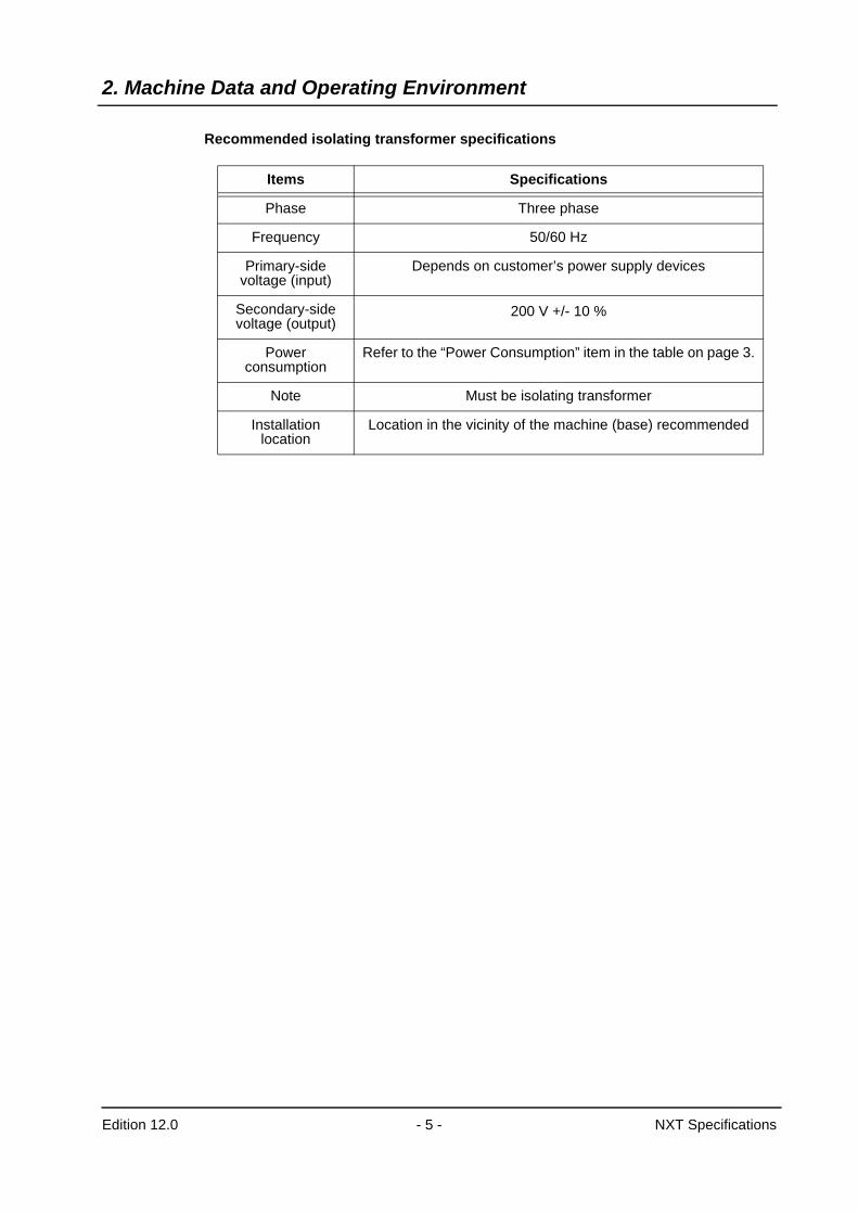
Recommended isolating transformer specifications
Items Specifications
Phase Three phase
Frequency 50/60 Hz
Primary-side voltage (input)
Depends on customer’s power supply devices
Secondary-side voltage (output)
200 V +/- 10 %
Power consumption
Refer to the “Power Consumption” item in the table on page 3.
Note Must be isolating transformer
Installation location
Location in the vicinity of the machine (base) recommended
3. Machine Specifications
Edition 12.0 - 6 - NXT Specifications
3. Machine Specifications3.1 Machine Specifications
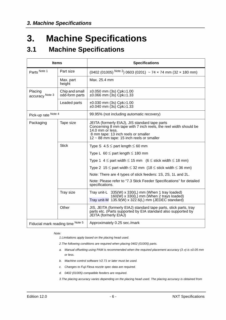
Note:1.Limitations apply based on the placing head used.
2.The following conditions are required when placing 0402 (01005) parts.
a. Manual offsetting using PAM is recommended when the required placement accuracy (3 σ) is ±0.05 mm or less.
b. Machine control software V2.71 or later must be used.
c. Changes to Fuji Flexa nozzle spec data are required.
d. 0402 (01005) compatible feeders are required.
3.The placing accuracy varies depending on the placing head used. The placing accuracy is obtained from
Items Specifications
Parts Note 1 Part size (0402 (01005) Note 2) 0603 (0201) ~ 74 × 74 mm (32 × 180 mm)
Max. part height
Max. 25.4 mm
Placing accuracy Note 3
Chip and small odd-form parts
±0.050 mm (3s) Cpk≥1.00±0.066 mm (3s) Cpk≥1.33
Leaded parts ±0.030 mm (3s) Cpk≥1.00±0.040 mm (3s) Cpk≥1.33
Pick-up rate Note 4 99.95% (not including automatic recovery)
Packaging Tape size JEITA (formerly EIAJ), JIS standard tape partsConcerning 8 mm tape with 7 inch reels, the reel width should be 14.0 mm or less. 8 mm tape: 13 inch reels or smaller12 ~ 88 mm tape: 15 inch reels or smaller
Stick Type S 4.5 ≤ part length ≤ 60 mm
Type L 60 ≤ part length ≤ 180 mm
Type 1 4 ≤ part width ≤ 15 mm (6 ≤ stick width ≤ 18 mm)
Type 2 15 ≤ part width ≤ 32 mm (18 ≤ stick width ≤ 36 mm)
Note: There are 4 types of stick feeders: 1S, 2S, 1L and 2L.
Note: Please refer to “7.3 Stick Feeder Specifications” for detailed specifications.
Tray size Tray unit-L 335(W) x 330(L) mm (When 1 tray loaded) 160(W) x 330(L) mm (When 2 trays loaded)Tray unit-M 135.9(W) x 322.6(L) mm (JEDEC standard)
Other JIS, JEITA (formerly EIAJ) standard tape parts, stick parts, tray parts etc. (Parts supported by EIA standard also supported by JEITA (formerly EIAJ)
Fiducial mark reading time Note 5 Approximately 0.25 sec./mark
3. Machine Specifications
Edition 12.0 - 7 - NXT Specifications
tests conducted by Fuji. Parts rotational offset is not considered. Also, the above placing accuracy may not be obtained depending on the quality of the PCB and the parts that are placed.
4.Obtained from tests conducted by Fuji. Errors due to packaging are not included.
5.Obtained when reading a 1.2 mm diameter mark, excluding the time required to travel from mark to mark, and to make adjustments for mark shape variations and location errors.
3. Machine Specifications
Edition 12.0 - 8 - NXT Specifications
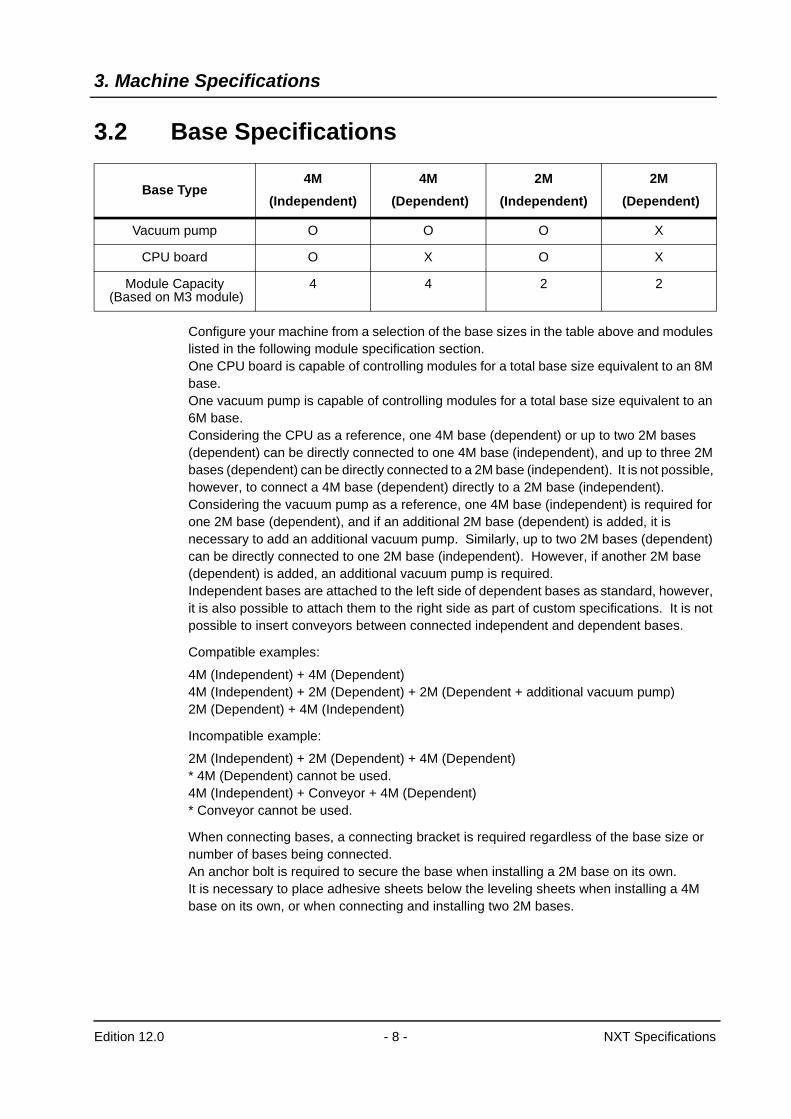
3.2 Base Specifications
Configure your machine from a selection of the base sizes in the table above and modules listed in the following module specification section.One CPU board is capable of controlling modules for a total base size equivalent to an 8M base. One vacuum pump is capable of controlling modules for a total base size equivalent to an 6M base.Considering the CPU as a reference, one 4M base (dependent) or up to two 2M bases (dependent) can be directly connected to one 4M base (independent), and up to three 2M bases (dependent) can be directly connected to a 2M base (independent). It is not possible, however, to connect a 4M base (dependent) directly to a 2M base (independent).Considering the vacuum pump as a reference, one 4M base (independent) is required for one 2M base (dependent), and if an additional 2M base (dependent) is added, it is necessary to add an additional vacuum pump. Similarly, up to two 2M bases (dependent) can be directly connected to one 2M base (independent). However, if another 2M base (dependent) is added, an additional vacuum pump is required.Independent bases are attached to the left side of dependent bases as standard, however, it is also possible to attach them to the right side as part of custom specifications. It is not possible to insert conveyors between connected independent and dependent bases.
Compatible examples:
4M (Independent) + 4M (Dependent)4M (Independent) + 2M (Dependent) + 2M (Dependent + additional vacuum pump)2M (Dependent) + 4M (Independent)
Incompatible example:
2M (Independent) + 2M (Dependent) + 4M (Dependent)* 4M (Dependent) cannot be used.4M (Independent) + Conveyor + 4M (Dependent)* Conveyor cannot be used.
When connecting bases, a connecting bracket is required regardless of the base size or number of bases being connected.An anchor bolt is required to secure the base when installing a 2M base on its own.It is necessary to place adhesive sheets below the leveling sheets when installing a 4M base on its own, or when connecting and installing two 2M bases.
Base Type4M
(Independent)4M
(Dependent)2M
(Independent)2M
(Dependent)
Vacuum pump O O O X
CPU board O X O X
Module Capacity (Based on M3 module)
4 4 2 2
3. Machine Specifications
Edition 12.0 - 9 - NXT Specifications
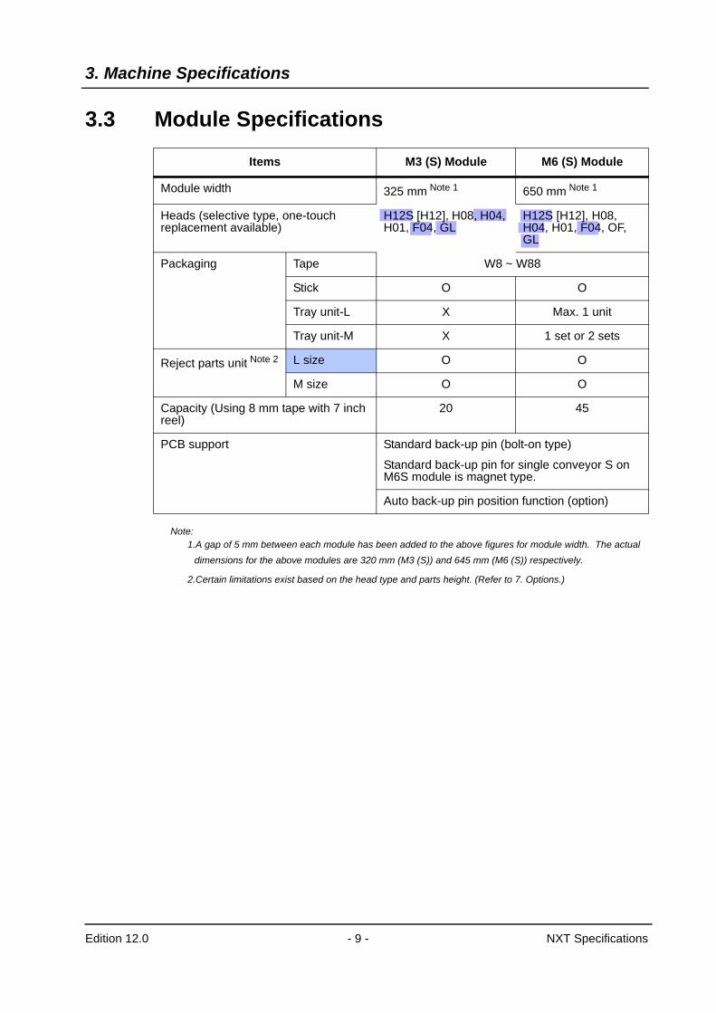
3.3 Module Specifications
Note:1.A gap of 5 mm between each module has been added to the above figures for module width. The actual
dimensions for the above modules are 320 mm (M3 (S)) and 645 mm (M6 (S)) respectively.
2.Certain limitations exist based on the head type and parts height. (Refer to 7. Options.)
Items M3 (S) Module M6 (S) Module
Module width 325 mm Note 1 650 mm Note 1
Heads (selective type, one-touch replacement available)
H12S [H12], H08, H04, H01, F04, GL
H12S [H12], H08, H04, H01, F04, OF, GL
Packaging Tape W8 ~ W88
Stick O O
Tray unit-L X Max. 1 unit
Tray unit-M X 1 set or 2 sets
Reject parts unit Note 2 L size O O
M size O O
Capacity (Using 8 mm tape with 7 inch reel)
20 45
PCB support Standard back-up pin (bolt-on type)
Standard back-up pin for single conveyor S on M6S module is magnet type.
Auto back-up pin position function (option)
3. Machine Specifications
Edition 12.0 - 10 - NXT Specifications
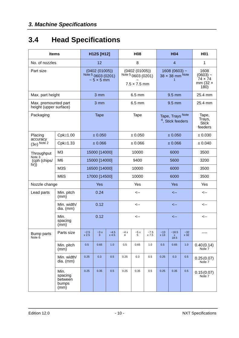
3.4 Head Specifications
Items H12S [H12] H08 H04 H01
No. of nozzles 12 8 4 1
Part size (0402 (01005)) Note 5 0603 (0201)
~ 5 × 5 mm
(0402 (01005)) Note 5 0603 (0201)
~ 7.5 × 7.5 mm
1608 (0603) ~ 38 × 38 mm Note
1
1608 (0603) ~ 74 × 74
mm (32 × 180)
Max. part height 3 mm 6.5 mm 9.5 mm 25.4 mm
Max. premounted part height (upper surface)
3 mm 6.5 mm 9.5 mm 25.4 mm
Packaging Tape Tape Tape, Trays Note 4, Stick feeders
Tape, Trays, Stick
feeders
Placing accuracy (3σ) Note 2
Cpk≥1.00 ± 0.050 ± 0.050 ± 0.050 ± 0.030
Cpk≥1.33 ± 0.066 ± 0.066 ± 0.066 ± 0.040
Throughput Note 3 (cph (chips/hr))
M3 15000 [14000] 10000 6000 3500
M6 15000 [14000] 9400 5600 3200
M3S 16500 [14000] 10000 6000 3500
M6S 17000 [14500] 10000 6000 3500
Nozzle change Yes Yes Yes Yes
Lead parts Min. pitch (mm)
0.24 <-- <-- <--
Min. width/dia. (mm)
0.12 <-- <-- <--
Min. spacing (mm)
0.12 <-- <-- <--
Bump parts Note 6
Parts size ~2.5 x 2.5
~3 x 3
~4.5 x 4.5
~4 x 4
~5 x 5
~7.5 x 7.5
~13 x 13
~18.5 x
18.5
~32 x 32
----
Min. pitch (mm)
0.5 0.65 1.0 0.5 0.65 1.0 0.5 0.65 1.0 0.40 (0.14) Note 7
Min. width/dia. (mm)
0.25 0.3 0.5 0.25 0.3 0.5 0.25 0.3 0.5 0.25 (0.07) Note 7
Min. spacing between bumps (mm)
0.25 0.35 0.5 0.25 0.35 0.5 0.25 0.35 0.5 0.15 (0.07) Note 7
3. Machine Specifications
Edition 12.0 - 11 - NXT Specifications
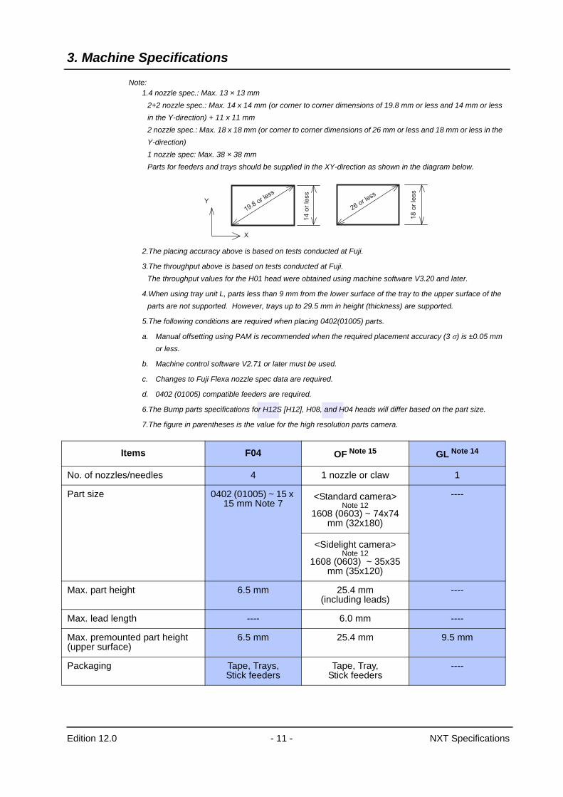
Note:1.4 nozzle spec.: Max. 13 × 13 mm
2+2 nozzle spec.: Max. 14 x 14 mm (or corner to corner dimensions of 19.8 mm or less and 14 mm or less in the Y-direction) + 11 x 11 mm2 nozzle spec.: Max. 18 x 18 mm (or corner to corner dimensions of 26 mm or less and 18 mm or less in the Y-direction) 1 nozzle spec: Max. 38 × 38 mmParts for feeders and trays should be supplied in the XY-direction as shown in the diagram below.
2.The placing accuracy above is based on tests conducted at Fuji.
3.The throughput above is based on tests conducted at Fuji. The throughput values for the H01 head were obtained using machine software V3.20 and later.
4.When using tray unit L, parts less than 9 mm from the lower surface of the tray to the upper surface of the parts are not supported. However, trays up to 29.5 mm in height (thickness) are supported.
5.The following conditions are required when placing 0402(01005) parts.
a. Manual offsetting using PAM is recommended when the required placement accuracy (3 σ) is ±0.05 mm or less.
b. Machine control software V2.71 or later must be used.
c. Changes to Fuji Flexa nozzle spec data are required.
d. 0402 (01005) compatible feeders are required.
6.The Bump parts specifications for H12S [H12], H08, and H04 heads will differ based on the part size.
7.The figure in parentheses is the value for the high resolution parts camera.
14
or
less
X
Y
18
or
less
19.8 or less
26 or less
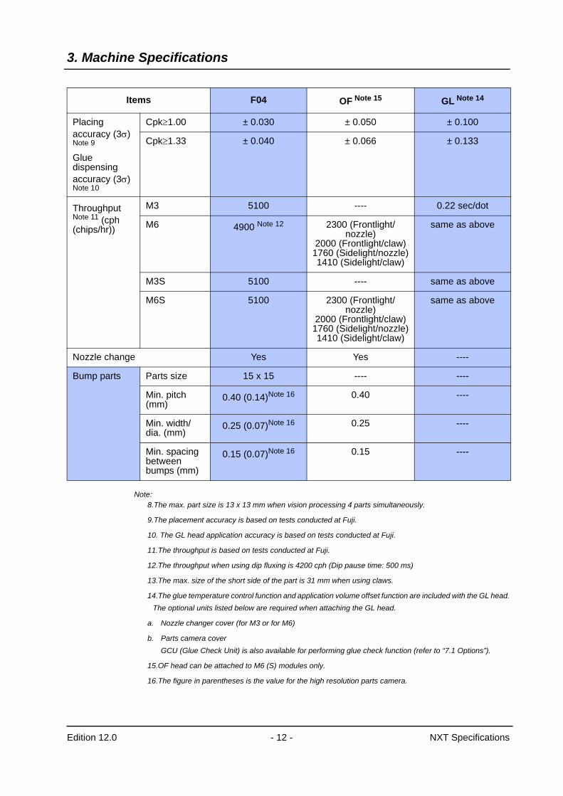
Items F04 OF Note 15 GL Note 14
No. of nozzles/needles 4 1 nozzle or claw 1
Part size 0402 (01005) ~ 15 x 15 mm Note 7
<Standard camera> Note 12
1608 (0603) ~ 74x74 mm (32x180)
----
<Sidelight camera> Note 12
1608 (0603) ~ 35x35 mm (35x120)
Max. part height 6.5 mm 25.4 mm (including leads)
----
Max. lead length ---- 6.0 mm ----
Max. premounted part height (upper surface)
6.5 mm 25.4 mm 9.5 mm
Packaging Tape, Trays, Stick feeders
Tape, Tray, Stick feeders
----
3. Machine Specifications
Edition 12.0 - 12 - NXT Specifications
Note:8.The max. part size is 13 x 13 mm when vision processing 4 parts simultaneously.
9.The placement accuracy is based on tests conducted at Fuji.
10. The GL head application accuracy is based on tests conducted at Fuji.
11.The throughput is based on tests conducted at Fuji.
12.The throughput when using dip fluxing is 4200 cph (Dip pause time: 500 ms)
13.The max. size of the short side of the part is 31 mm when using claws.
14.The glue temperature control function and application volume offset function are included with the GL head.The optional units listed below are required when attaching the GL head.
a. Nozzle changer cover (for M3 or for M6)
b. Parts camera coverGCU (Glue Check Unit) is also available for performing glue check function (refer to “7.1 Options”).
15.OF head can be attached to M6 (S) modules only.
16.The figure in parentheses is the value for the high resolution parts camera.
Placing accuracy (3σ) Note 9
Glue dispensing accuracy (3σ) Note 10
Cpk≥1.00 ± 0.030 ± 0.050 ± 0.100
Cpk≥1.33 ± 0.040 ± 0.066 ± 0.133
Throughput Note 11 (cph (chips/hr))
M3 5100 ---- 0.22 sec/dot
M6 4900 Note 12 2300 (Frontlight/nozzle)
2000 (Frontlight/claw)1760 (Sidelight/nozzle)1410 (Sidelight/claw)
same as above
M3S 5100 ---- same as above
M6S 5100 2300 (Frontlight/nozzle)
2000 (Frontlight/claw)1760 (Sidelight/nozzle)1410 (Sidelight/claw)
same as above
Nozzle change Yes Yes ----
Bump parts Parts size 15 x 15 ---- ----
Min. pitch (mm)
0.40 (0.14)Note 16 0.40 ----
Min. width/dia. (mm)
0.25 (0.07)Note 16 0.25 ----
Min. spacing between bumps (mm)
0.15 (0.07)Note 16 0.15 ----
Items F04 OF Note 15 GL Note 14
3. Machine Specifications
Edition 12.0 - 13 - NXT Specifications
3.5 PCB Conveyance
Items Specifications
PCB flow direction Left -> right, right -> left
Conveyance height 900 (+15, -5) mm (950 (+15, -5) mm)The conveyance height is specified when placing a machine order.
Conveyance method Belt conveyance
Loading time
Double conveyor
0 sec. during continuous operation Note 1
Single conveyor
4.2 sec. (Conveyance time between modules when using only M3 (S) modules) Note 2
5.1 sec. (Conveyance time between modules when using only M6 (S) modules) Note 2
Single conveyor S Note 3
2.3 ~ 4.0 sec. (M6S modules) Note 4
Maximum load Max. 1 kg (Up to a max. of 3 kg when using roller conveyor.)
Conveyor width change Fixed front reference rail with motor assisted adjustable side.
ItemsDouble conveyor/Single conveyor
Single conveyor S
Applicable module M3/M3S/M6/M6S M6S
Conveyor width change Automatic width change using a motor
Automatic width change using a motor
Max. conveyance speed 426 mm/sec. 800 mm/sec. (High)426 mm/sec. (Middle/Low)
Conveyance speed mode Note 5
Fixed Three steps(High/Middle/Low)
Overlap conveyance Note 6 Not available Available for panels with 350 mm in length or less
Panel clamping method Air cylinder Motor
Clamping force control Fixed Variable (High/Low) Note 7
Clamping stroke Fixed Variable depending on panel thickness in jobs
Panel stopper No stopper Mechanical stopper
PCB stop presence check sensor
Mark camera Limited reflective sensor
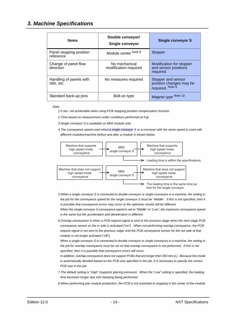
3. Machine Specifications
Edition 12.0 - 14 - NXT Specifications
Note:1.0 sec. not achievable when using PCB stopping position compensation function.
2.Time based on measurement under conditions performed at Fuji.
3.Single conveyor S is available on M6S module only.
4.The conveyance speed used when a single conveyor S or a conveyor with the same speed is used with different modules/machine before and after a module is shown below.
5.When a single conveyor S is connected to double conveyor or single conveyors in a machine, the setting in the job for the conveyance speed for the single conveyor S must be “Middle”. If this is not specified, then it is possible that conveyance errors may occur or the optimizer results will be different. When the single conveyor S conveyance speed is set to “Middle” or “Low”, the maximum conveyance speed is the same but the acceleration and deceleration is different.
6.Overlap conveyance is when a PCB request signal is sent to the previous stage when the next stage PCB conveyance sensor on the in side is activated (“on”). When not performing overlap conveyance, the PCB request signal is not sent to the previous stage until the PCB conveyance sensor for the out side of that module is not longer activated (“off”). When a single conveyor S is connected to double conveyor or single conveyors in a machine, the setting in the job for overlap conveyance must be set so that overlap conveyance is not performed. If this is not specified, then it is possible that conveyance errors will occur. In addition, overlap conveyance does not support PCBs that are longer then 350 mm (L). Because this mode is automatically decided based on the PCB size specified in the job, it is necessary to specify the correct PCB size in the job.
7.The default setting is “High” (supports placing pressure). When the “Low” setting is specified, the loading time becomes longer due soft clamping being performed.
8.When performing pair module production, the PCB is not restricted to stopping in the center of the module
Panel stopping position reference
Module center Note 8 Stopper
Change of panel flow direction
No mechanical modification required
Modification for stopper and sensor positions required.
Handling of panels with slits, etc.
No measures required Stopper and sensor position changes may be required. Note 9
Standard back-up pins Bolt-on type Magnet type Note 10
ItemsDouble conveyor/Single conveyor
Single conveyor S
Machine that supports
high speed mode
conveyance
Machine that supports
high speed mode
conveyance
M6S
single conveyor S
M6S
single conveyor S
Loading time is within the specifications.
Machine that does not support
high speed mode
conveyance
Machine that does not support
high speed mode
conveyance
The loading time is the same time as
that for the single conveyor.
3. Machine Specifications
Edition 12.0 - 15 - NXT Specifications
for M3(S) and M3(S) modules.
9.To support PCBs with cutouts, it is necessary to change the ball screw cover plate and PCB stopper installed on the backup plate in order to prevent interference with the PCB check sensor. In addition, there are PCB size limitations due to this when using PCBs with cutouts.
• Sensor adjusting range with the standard ball screw cover plate: approximately 14 mm in the Y-direction.From the center of the sensor position to the reference rail in the Y-direction: approximately 23.5 to 37.5 mm.PCB size matches the possible sizes for the single conveyor S.
• Sensor adjusting range with the PCB cutout compatible ball screw cover plate: approximately 149 mm in the Y-direction.From the center of the sensor position to the reference rail in the Y-direction: approximately 23.5 to 172.5 mm.There is a PCB size limitation: The PCB must be 100 mm (W) or wider.When changing the plate to support PCBs with cutouts, it is necessary to change to the special PCB stopper. The machine recognizes that the automatic backup pin area has changed due to changing the plate for the detection of the PCB stopper position.The cutout compatible ball screw cover plate and PCB stopper are attached as standard for the single conveyor S machine specification.
10.The same type with optional auto backup pin.
3. Machine Specifications
Edition 12.0 - 16 - NXT Specifications
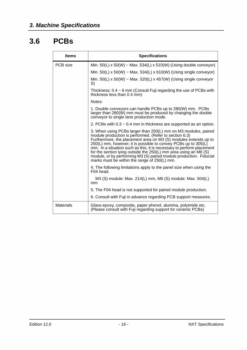
3.6 PCBs
Items Specifications
PCB size Min. 50(L) x 50(W) ~ Max. 534(L) x 510(W) (Using double conveyor)
Min. 50(L) x 50(W) ~ Max. 534(L) x 610(W) (Using single conveyor)
Min. 50(L) x 50(W) ~ Max. 520(L) x 457(W) (Using single conveyor S)
Thickness: 0.4 ~ 6 mm (Consult Fuji regarding the use of PCBs with thickness less than 0.4 mm)
Notes:
1. Double conveyors can handle PCBs up to 280(W) mm. PCBs larger than 280(W) mm must be produced by changing the double conveyor to single lane production mode.
2. PCBs with 0.3 ~ 0.4 mm in thickness are supported as an option.
3. When using PCBs larger than 250(L) mm on M3 modules, paired module production is performed. (Refer to section 6.3)Furthermore, the placement area on M3 (S) modules extends up to 250(L) mm, however, it is possible to convey PCBs up to 305(L) mm. In a situation such as this, it is necessary to perform placement for the section lying outside the 250(L) mm area using an M6 (S) module, or by performing M3 (S) paired module production. Fiducial marks must be within the range of 250(L) mm.
4. The following limitations apply to the panel size when using the F04 head.
M3 (S) module: Max. 214(L) mm, M6 (S) module: Max. 504(L) mm
5. The F04 head is not supported for paired module production.
6. Consult with Fuji in advance regarding PCB support measures.
Materials Glass-epoxy, composite, paper phenol, alumina, polyimide etc. (Please consult with Fuji regarding support for ceramic PCBs)
3. Machine Specifications
Edition 12.0 - 17 - NXT Specifications
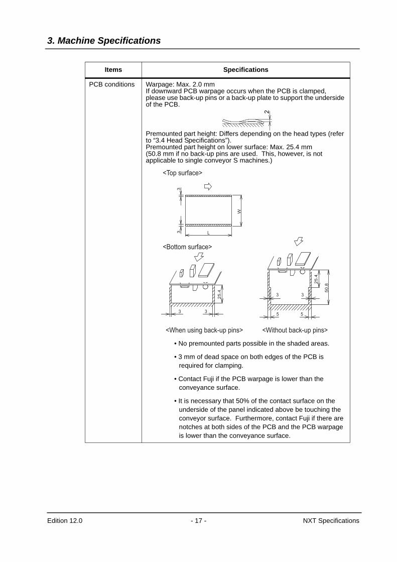
PCB conditions Warpage: Max. 2.0 mm If downward PCB warpage occurs when the PCB is clamped, please use back-up pins or a back-up plate to support the underside of the PCB.
Premounted part height: Differs depending on the head types (refer to “3.4 Head Specifications”).Premounted part height on lower surface: Max. 25.4 mm (50.8 mm if no back-up pins are used. This, however, is not applicable to single conveyor S machines.)
• No premounted parts possible in the shaded areas.
• 3 mm of dead space on both edges of the PCB is required for clamping.
• Contact Fuji if the PCB warpage is lower than the conveyance surface.
• It is necessary that 50% of the contact surface on the underside of the panel indicated above be touching the conveyor surface. Furthermore, contact Fuji if there are notches at both sides of the PCB and the PCB warpage is lower than the conveyance surface.
Items Specifications
2
33 L
W
3 3
25
.4
5 5
3 3
50
.8
25
.4
<Top surface>
<Bottom surface>
<When using back-up pins> <Without back-up pins>
4. Machine Structure
Edition 12.0 - 18 - NXT Specifications
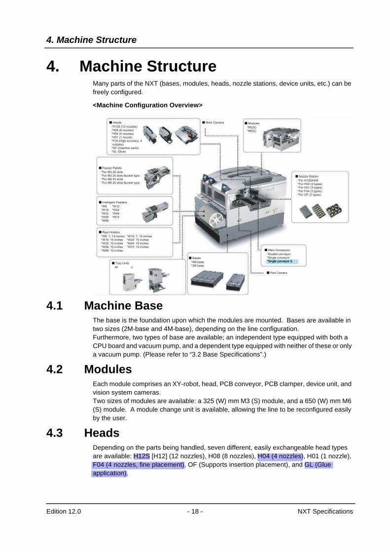
4. Machine StructureMany parts of the NXT (bases, modules, heads, nozzle stations, device units, etc.) can be freely configured.
<Machine Configuration Overview>
4.1 Machine BaseThe base is the foundation upon which the modules are mounted. Bases are available in two sizes (2M-base and 4M-base), depending on the line configuration.Furthermore, two types of base are available; an independent type equipped with both a CPU board and vacuum pump, and a dependent type equipped with neither of these or only a vacuum pump. (Please refer to “3.2 Base Specifications”.)
4.2 ModulesEach module comprises an XY-robot, head, PCB conveyor, PCB clamper, device unit, and vision system cameras.Two sizes of modules are available: a 325 (W) mm M3 (S) module, and a 650 (W) mm M6 (S) module. A module change unit is available, allowing the line to be reconfigured easily by the user.
4.3 HeadsDepending on the parts being handled, seven different, easily exchangeable head types are available: H12S [H12] (12 nozzles), H08 (8 nozzles), H04 (4 nozzles), H01 (1 nozzle), F04 (4 nozzles, fine placement), OF (Supports insertion placement), and GL (Glue application).
Heads Mark Camera
*H12S (12 nozzles)
*H08 (8 nozzles)
*H04 (4 nozzles)
*H01 (1 nozzle)
*F04 (High accuracy, 4
nozzles)
*OF (Insertion parts)
*GL (Glue)
Feeder Pallets
*For M3 20 slots
*For M3 20 slots Bucket type
*For M6 45 slots
*For M6 45 slots Bucket type
Bases
Part Camera
*4M base
*2M base
Main Conveyors
*Double conveyor
*Single conveyor
Nozzle Station
*For H12S/H08
*For H04 (2 types)
*For H01 (3 types)
*For F04 (3 types)
*For OF (3 types)
Modules
*M3(S)
*M6(S)
Intelligent Feeders
*W8
*W16
*W32
*W56
*W88
*W12
*W24
*W44
*W72
Reel Holders
*W8: 7, 13 inches
*W16: 15 inches
*W32: 15 inches
*W56: 15 inches
*W88: 15 inches
Tray Units
-M -L
*W12: 7, 15 inches
*W24: 15 inches
*W44: 15 inches
*W72: 15 inches
4. Machine Structure
Edition 12.0 - 19 - NXT Specifications
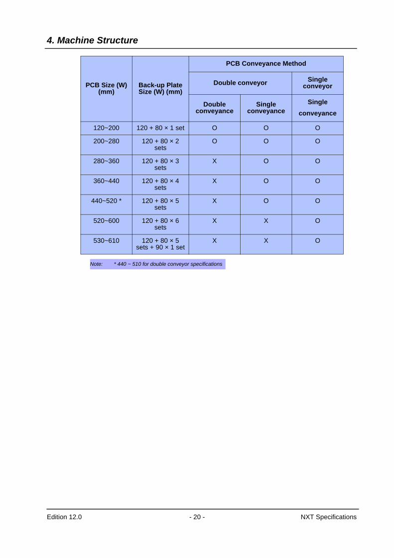
4.4 Main ConveyorThe NXT PCB conveyance system provides shock-free transport of the PCB, with a motor driven, conveyor width adjustment function, and simple PCB flow direction change capabilities.The double conveyor not only conveys and produces the same PCB, but can also be used to convey and produce PCBs of different widths, and the conveyor widths can be changed independently. Replace the back-up plates based on the size of the PCB being produced.
Note:1.PCBs of up to 50 to 280 (W) mm (double conveyor) and 50 to 610 (W) mm (single conveyor) can be used
on standard specification back-up plates when using manual back-up pins. Support for other back-up pin allocation methods and PCB sizes is optional.
2.When using this back-up plate, the rear conveyor is adjusted to a position further forward from the standard position (PCB width: 280 mm). As a result, when producing PCBs on the rear conveyor, the Y-axis movement distance is shorter when compared with the movement distance when the rear conveyor is at its standard position, therefore resulting in a faster cycle time.
The back-up plate combinations when using automatic back-up pins for paired module production (M3 (S) modules) are as follows.
PCB Size (W)(mm)
Back-up Plate
Size (W) (mm)
PCB Conveyance Method
Double conveyor Single conveyor
Single conveyor S
Double conveyance
Single conveyance
Single conveyance
Single conveyance
50~280 Note 1 280 O O
50~200 Note 2 200 O O
50~165 Note 2 165 O O
50~360 360 X O
280~510 510 X O
50~610 Note 1 610 O
50~457 457 O
PCB Size (W)(mm)
Back-up PlateSize (W) (mm)
PCB Conveyance Method
Double conveyor Single conveyor
Double conveyance
Single conveyance
Single conveyance
50~120 120 O O O
4. Machine Structure
Edition 12.0 - 20 - NXT Specifications
Note: * 440 ~ 510 for double conveyor specifications
120~200 120 + 80 × 1 set O O O
200~280 120 + 80 × 2 sets
O O O
280~360 120 + 80 × 3 sets
X O O
360~440 120 + 80 × 4 sets
X O O
440~520 * 120 + 80 × 5 sets
X O O
520~600 120 + 80 × 6 sets
X X O
530~610 120 + 80 × 5 sets + 90 × 1 set
X X O
PCB Size (W)(mm)
Back-up PlateSize (W) (mm)
PCB Conveyance Method
Double conveyor Single conveyor
Double conveyance
Single conveyance
Single conveyance
4. Machine Structure
Edition 12.0 - 21 - NXT Specifications
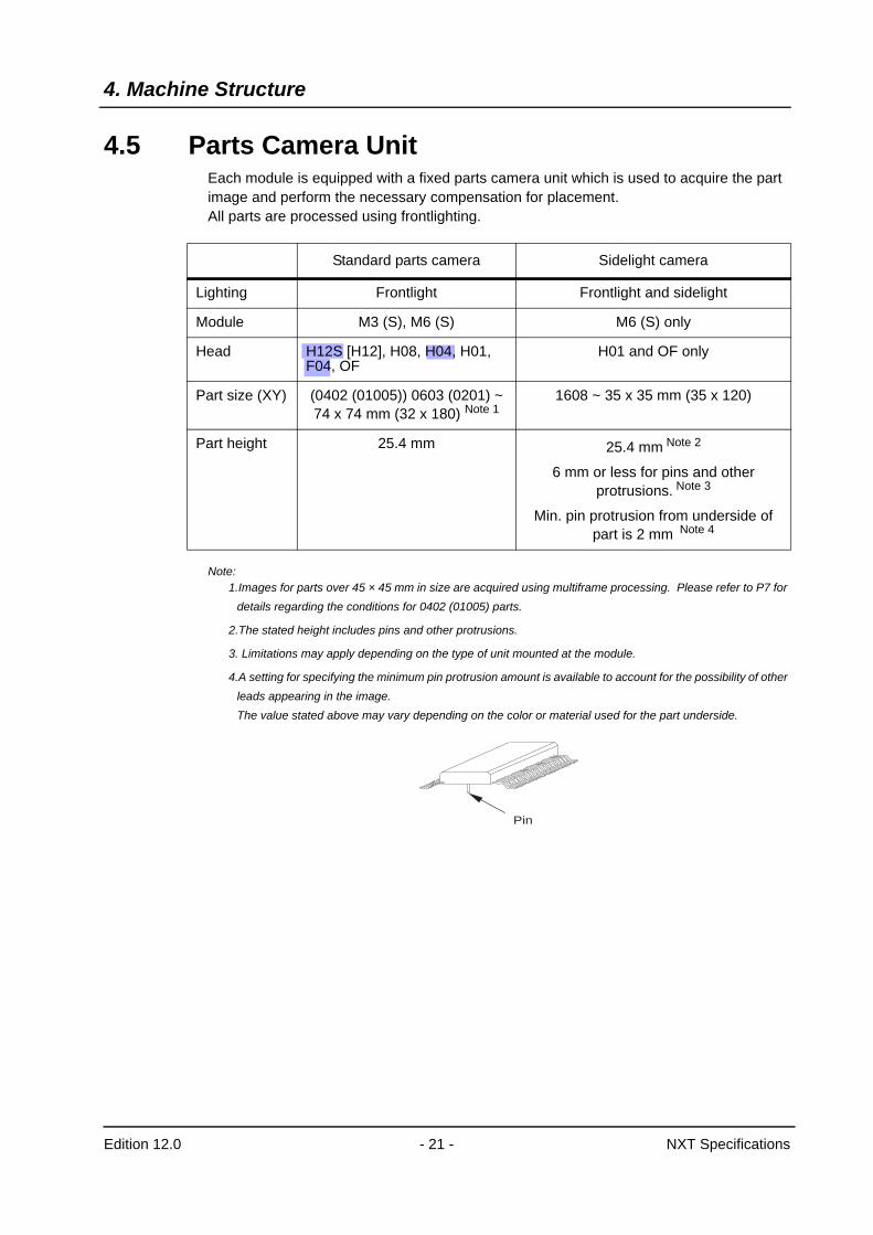
4.5 Parts Camera UnitEach module is equipped with a fixed parts camera unit which is used to acquire the part image and perform the necessary compensation for placement.All parts are processed using frontlighting.
Note:1.Images for parts over 45 × 45 mm in size are acquired using multiframe processing. Please refer to P7 for
details regarding the conditions for 0402 (01005) parts.
2.The stated height includes pins and other protrusions.
3. Limitations may apply depending on the type of unit mounted at the module.
4.A setting for specifying the minimum pin protrusion amount is available to account for the possibility of other leads appearing in the image.The value stated above may vary depending on the color or material used for the part underside.
Standard parts camera Sidelight camera
Lighting Frontlight Frontlight and sidelight
Module M3 (S), M6 (S) M6 (S) only
Head H12S [H12], H08, H04, H01, F04, OF
H01 and OF only
Part size (XY) (0402 (01005)) 0603 (0201) ~ 74 x 74 mm (32 x 180) Note 1
1608 ~ 35 x 35 mm (35 x 120)
Part height 25.4 mm 25.4 mm Note 2
6 mm or less for pins and other protrusions. Note 3
Min. pin protrusion from underside of part is 2 mm Note 4
Pin
4. Machine Structure
Edition 12.0 - 22 - NXT Specifications
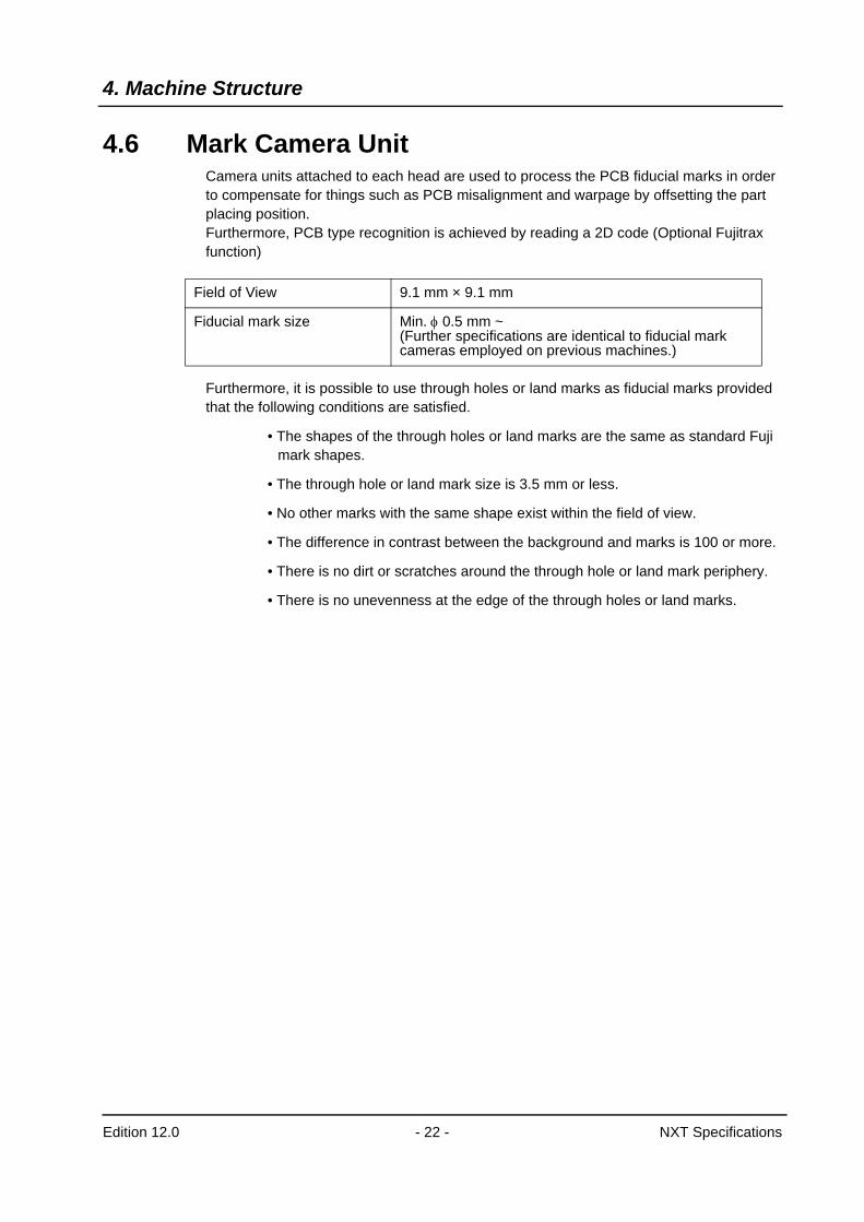
4.6 Mark Camera UnitCamera units attached to each head are used to process the PCB fiducial marks in order to compensate for things such as PCB misalignment and warpage by offsetting the part placing position.Furthermore, PCB type recognition is achieved by reading a 2D code (Optional Fujitrax function)
Furthermore, it is possible to use through holes or land marks as fiducial marks provided that the following conditions are satisfied.
• The shapes of the through holes or land marks are the same as standard Fuji mark shapes.
• The through hole or land mark size is 3.5 mm or less.
• No other marks with the same shape exist within the field of view.
• The difference in contrast between the background and marks is 100 or more.
• There is no dirt or scratches around the through hole or land mark periphery.
• There is no unevenness at the edge of the through holes or land marks.
Field of View 9.1 mm × 9.1 mm
Fiducial mark size Min. φ 0.5 mm ~ (Further specifications are identical to fiducial mark cameras employed on previous machines.)
4. Machine Structure
Edition 12.0 - 23 - NXT Specifications
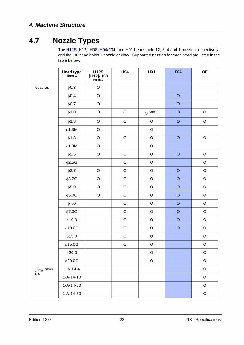
4.7 Nozzle TypesThe H12S [H12], H08, H04/F04, and H01 heads hold 12, 8, 4 and 1 nozzles respectively, and the OF head holds 1 nozzle or claw. Supported nozzles for each head are listed in the table below.
Head type Note 1
H12S [H12]/H08
Note 2
H04 H01 F04 OF
Nozzles φ0.3 O
φ0.4 O O
φ0.7 O O
φ1.0 O O O Note 3 O O
φ1.3 O O O O O
φ1.3M O O
φ1.8 O O O O O
φ1.8M O O
φ2.5 O O O O O
φ2.5G O O O
φ3.7 O O O O O
φ3.7G O O O O O
φ5.0 O O O O O
φ5.0G O O O O O
φ7.0 O O O O
φ7.0G O O O O
φ10.0 O O O O
φ10.0G O O O O
φ15.0 O O O
φ15.0G O O O
φ20.0 O O
φ20.0G O O
Claw Notes 4, 5
1-A-14-4 O
1-A-14-10 O
1-A-14-30 O
1-A-14-60 O
4. Machine Structure
Edition 12.0 - 24 - NXT Specifications
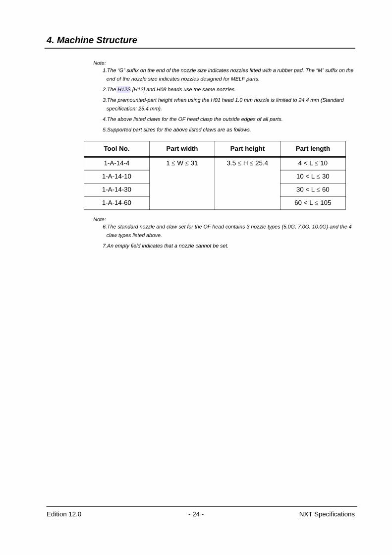
Note:1.The “G” suffix on the end of the nozzle size indicates nozzles fitted with a rubber pad. The “M” suffix on the
end of the nozzle size indicates nozzles designed for MELF parts.
2.The H12S [H12] and H08 heads use the same nozzles.
3.The premounted-part height when using the H01 head 1.0 mm nozzle is limited to 24.4 mm (Standard specification: 25.4 mm).
4.The above listed claws for the OF head clasp the outside edges of all parts.
5.Supported part sizes for the above listed claws are as follows.
Note:6.The standard nozzle and claw set for the OF head contains 3 nozzle types (5.0G, 7.0G, 10.0G) and the 4
claw types listed above.
7.An empty field indicates that a nozzle cannot be set.
Tool No. Part width Part height Part length
1-A-14-4 1 ≤ W ≤ 31 3.5 ≤ H ≤ 25.4 4 < L ≤ 10
1-A-14-10 10 < L ≤ 30
1-A-14-30 30 < L ≤ 60
1-A-14-60 60 < L ≤ 105
4. Machine Structure
Edition 12.0 - 25 - NXT Specifications
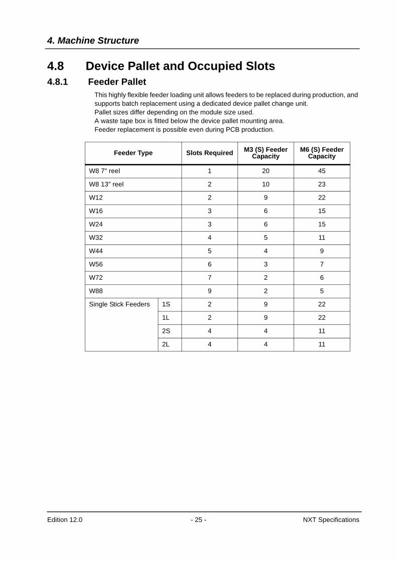
4.8 Device Pallet and Occupied Slots4.8.1 Feeder Pallet
This highly flexible feeder loading unit allows feeders to be replaced during production, and supports batch replacement using a dedicated device pallet change unit.Pallet sizes differ depending on the module size used.A waste tape box is fitted below the device pallet mounting area.Feeder replacement is possible even during PCB production.
Feeder Type Slots Required M3 (S) Feeder Capacity
M6 (S) Feeder Capacity
W8 7" reel 1 20 45
W8 13" reel 2 10 23
W12 2 9 22
W16 3 6 15
W24 3 6 15
W32 4 5 11
W44 5 4 9
W56 6 3 7
W72 7 2 6
W88 9 2 5
Single Stick Feeders 1S 2 9 22
1L 2 9 22
2S 4 4 11
2L 4 4 11
4. Machine Structure
Edition 12.0 - 26 - NXT Specifications
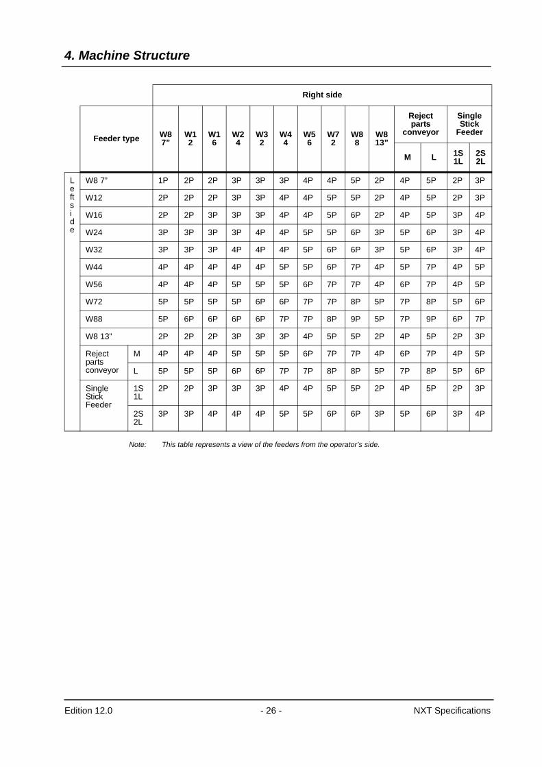
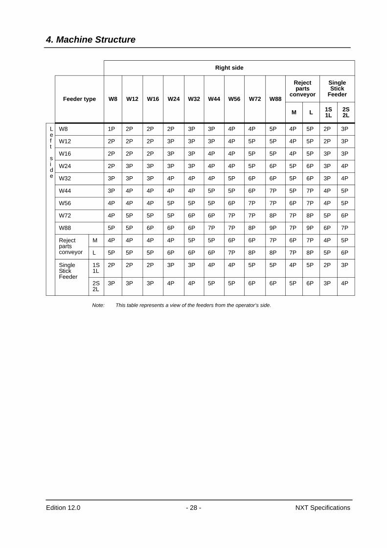
Note: This table represents a view of the feeders from the operator’s side.
Right side
Feeder type W8 7”
W12
W16
W24
W32
W44
W56
W72
W88
W8 13”
Reject parts
conveyor
Single Stick
Feeder
M L 1S 1L
2S 2L
Left side
W8 7” 1P 2P 2P 3P 3P 3P 4P 4P 5P 2P 4P 5P 2P 3P
W12 2P 2P 2P 3P 3P 4P 4P 5P 5P 2P 4P 5P 2P 3P
W16 2P 2P 3P 3P 3P 4P 4P 5P 6P 2P 4P 5P 3P 4P
W24 3P 3P 3P 3P 4P 4P 5P 5P 6P 3P 5P 6P 3P 4P
W32 3P 3P 3P 4P 4P 4P 5P 6P 6P 3P 5P 6P 3P 4P
W44 4P 4P 4P 4P 4P 5P 5P 6P 7P 4P 5P 7P 4P 5P
W56 4P 4P 4P 5P 5P 5P 6P 7P 7P 4P 6P 7P 4P 5P
W72 5P 5P 5P 5P 6P 6P 7P 7P 8P 5P 7P 8P 5P 6P
W88 5P 6P 6P 6P 6P 7P 7P 8P 9P 5P 7P 9P 6P 7P
W8 13” 2P 2P 2P 3P 3P 3P 4P 5P 5P 2P 4P 5P 2P 3P
Reject parts conveyor
M 4P 4P 4P 5P 5P 5P 6P 7P 7P 4P 6P 7P 4P 5P
L 5P 5P 5P 6P 6P 7P 7P 8P 8P 5P 7P 8P 5P 6P
Single Stick Feeder
1S 1L
2P 2P 3P 3P 3P 4P 4P 5P 5P 2P 4P 5P 2P 3P
2S 2L
3P 3P 4P 4P 4P 5P 5P 6P 6P 3P 5P 6P 3P 4P
4. Machine Structure
Edition 12.0 - 27 - NXT Specifications
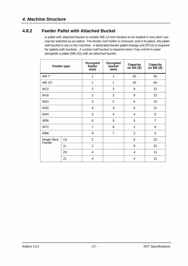
4.8.2 Feeder Pallet with Attached Bucket A pallet with attached bucket to enable W8 13-inch feeders to be loaded in one pitch can now be selected as an option. The feeder reel holder is removed, and in its place, the pallet with bucket is set on the machine. A dedicated feeder pallet change unit (PCU) is required for pallets with buckets. A custom half bucket is required when Tray unit-M is used alongside a pallet (M6 (S)) with an attached bucket.
Feeder typeOccupied
feeder slots
Occupied bucket slots
Capacity on M3 (S)
Capacity on M6 (S)
W8 7” 1 1 20 45
W8 13” 1 1 20 45
W12 2 2 9 22
W16 2 2 9 22
W24 3 2 6 15
W32 4 3 5 11
W44 5 4 4 9
W56 6 5 3 7
W72 7 6 2 6
W88 9 7 2 5
Single Stick Feeder
1S 2 9 22
1L 2 9 22
2S 4 4 11
2L 4 4 11
4. Machine Structure
Edition 12.0 - 28 - NXT Specifications
Note: This table represents a view of the feeders from the operator’s side.
Right side
Feeder type W8 W12 W16 W24 W32 W44 W56 W72 W88
Reject parts
conveyor
Single Stick
Feeder
M L 1S 1L
2S 2L
Left side
W8 1P 2P 2P 2P 3P 3P 4P 4P 5P 4P 5P 2P 3P
W12 2P 2P 2P 3P 3P 3P 4P 5P 5P 4P 5P 2P 3P
W16 2P 2P 2P 3P 3P 4P 4P 5P 5P 4P 5P 3P 3P
W24 2P 3P 3P 3P 3P 4P 4P 5P 6P 5P 6P 3P 4P
W32 3P 3P 3P 4P 4P 4P 5P 6P 6P 5P 6P 3P 4P
W44 3P 4P 4P 4P 4P 5P 5P 6P 7P 5P 7P 4P 5P
W56 4P 4P 4P 5P 5P 5P 6P 7P 7P 6P 7P 4P 5P
W72 4P 5P 5P 5P 6P 6P 7P 7P 8P 7P 8P 5P 6P
W88 5P 5P 6P 6P 6P 7P 7P 8P 9P 7P 9P 6P 7P
Reject parts conveyor
M 4P 4P 4P 4P 5P 5P 6P 6P 7P 6P 7P 4P 5P
L 5P 5P 5P 6P 6P 6P 7P 8P 8P 7P 8P 5P 6P
Single Stick Feeder
1S 1L
2P 2P 2P 3P 3P 4P 4P 5P 5P 4P 5P 2P 3P
2S 2L
3P 3P 3P 4P 4P 5P 5P 6P 6P 5P 6P 3P 4P
4. Machine Structure
Edition 12.0 - 29 - NXT Specifications
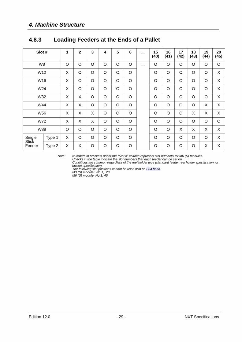
4.8.3 Loading Feeders at the Ends of a Pallet
Note: Numbers in brackets under the “Slot #” column represent slot numbers for M6 (S) modules.Checks in the table indicate the slot numbers that each feeder can be set on.Conditions are common regardless of the reel holder type (standard feeder reel holder specification, or bucket specification).The following slot positions cannot be used with an F04 head.M3 (S) module: No.1, 20M6 (S) module: No.1, 45
Slot # 1 2 3 4 5 6 ... 15(40)
16(41)
17(42)
18(43)
19(44)
20(45)
W8 O O O O O O ... O O O O O O
W12 X O O O O O O O O O O X
W16 X O O O O O O O O O O X
W24 X O O O O O O O O O O X
W32 X X O O O O O O O O O X
W44 X X O O O O O O O O X X
W56 X X X O O O O O O X X X
W72 X X X O O O O O O O O O
W88 O O O O O O O O X X X X
Single Stick Feeder
Type 1 X O O O O O O O O O O X
Type 2 X X O O O O O O O O X X
5. Machine Control System
Edition 12.0 - 30 - NXT Specifications
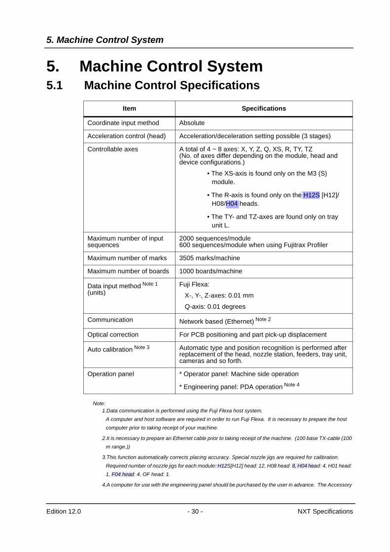
5. Machine Control System5.1 Machine Control Specifications
Note:1.Data communication is performed using the Fuji Flexa host system.
A computer and host software are required in order to run Fuji Flexa. It is necessary to prepare the host computer prior to taking receipt of your machine.
2.It is necessary to prepare an Ethernet cable prior to taking receipt of the machine. (100 base TX-cable (100 m range.))
3.This function automatically corrects placing accuracy. Special nozzle jigs are required for calibration. Required number of nozzle jigs for each module: H12S[H12] head: 12, H08 head: 8, H04 head: 4, H01 head: 1, F04 head: 4, OF head: 1.
4.A computer for use with the engineering panel should be purchased by the user in advance. The Accessory
Item Specifications
Coordinate input method Absolute
Acceleration control (head) Acceleration/deceleration setting possible (3 stages)
Controllable axes A total of 4 ~ 8 axes: X, Y, Z, Q, XS, R, TY, TZ(No. of axes differ depending on the module, head and device configurations.)
• The XS-axis is found only on the M3 (S) module.
• The R-axis is found only on the H12S [H12]/H08/H04 heads.
• The TY- and TZ-axes are found only on tray unit L.
Maximum number of input sequences
2000 sequences/module600 sequences/module when using Fujitrax Profiler
Maximum number of marks 3505 marks/machine
Maximum number of boards 1000 boards/machine
Data input method Note 1 (units)
Fuji Flexa:
X-, Y-, Z-axes: 0.01 mm
Q-axis: 0.01 degrees
Communication Network based (Ethernet) Note 2
Optical correction For PCB positioning and part pick-up displacement
Auto calibration Note 3 Automatic type and position recognition is performed after replacement of the head, nozzle station, feeders, tray unit, cameras and so forth.
Operation panel * Operator panel: Machine side operation
* Engineering panel: PDA operation Note 4
5. Machine Control System
Edition 12.0 - 31 - NXT Specifications
Software is a standard application of NXT (refer to “8.1.1 NXT Accessory Software”)
5.The NXT can be treated as one machine with bases and modules connected together, however, the maximum number of modules that can be connected is 32 when using only M3 (S) modules. An M6 (S) module is calculated as two M3 (S) modules. A line with more than 32 modules can be configured by setting multiple machines within the line. (Settings performed at Fuji Flexa)
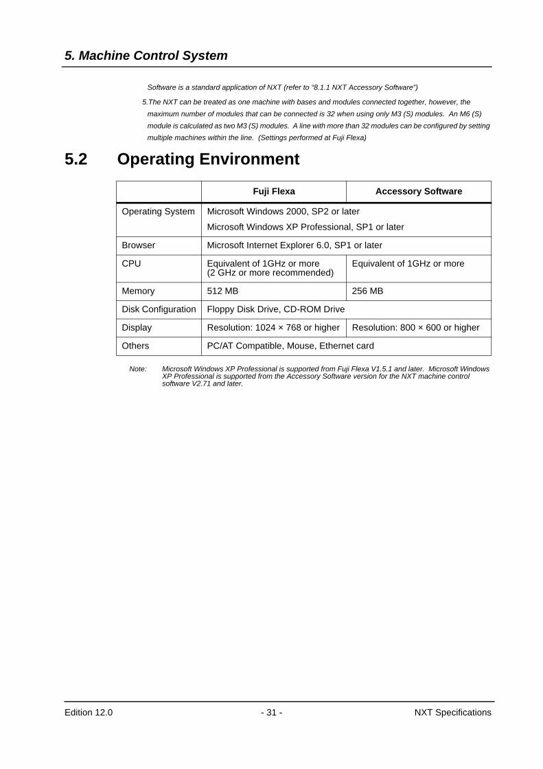
5.2 Operating Environment
Note: Microsoft Windows XP Professional is supported from Fuji Flexa V1.5.1 and later. Microsoft Windows XP Professional is supported from the Accessory Software version for the NXT machine control software V2.71 and later.
Fuji Flexa Accessory Software
Operating System Microsoft Windows 2000, SP2 or later
Microsoft Windows XP Professional, SP1 or later
Browser Microsoft Internet Explorer 6.0, SP1 or later
CPU Equivalent of 1GHz or more (2 GHz or more recommended)
Equivalent of 1GHz or more
Memory 512 MB 256 MB
Disk Configuration Floppy Disk Drive, CD-ROM Drive
Display Resolution: 1024 × 768 or higher Resolution: 800 × 600 or higher
Others PC/AT Compatible, Mouse, Ethernet card
6. Standard Functionality
Edition 12.0 - 32 - NXT Specifications
6. Standard Functionality6.1 Pick-up Position Detection
Pick-up accuracy is guaranteed by performing automatic pick-up position detection immediately after feeder replacement, pallet exchange, and head exchange.
6.2 Paired Production Mode (M3 (S) module)Production is shared between two modules when PCBs exceeding 250 mm in length are produced on M3 (S) modules.The machine heads can place parts in the production area of the adjacent module, therefore eliminating any dead space.
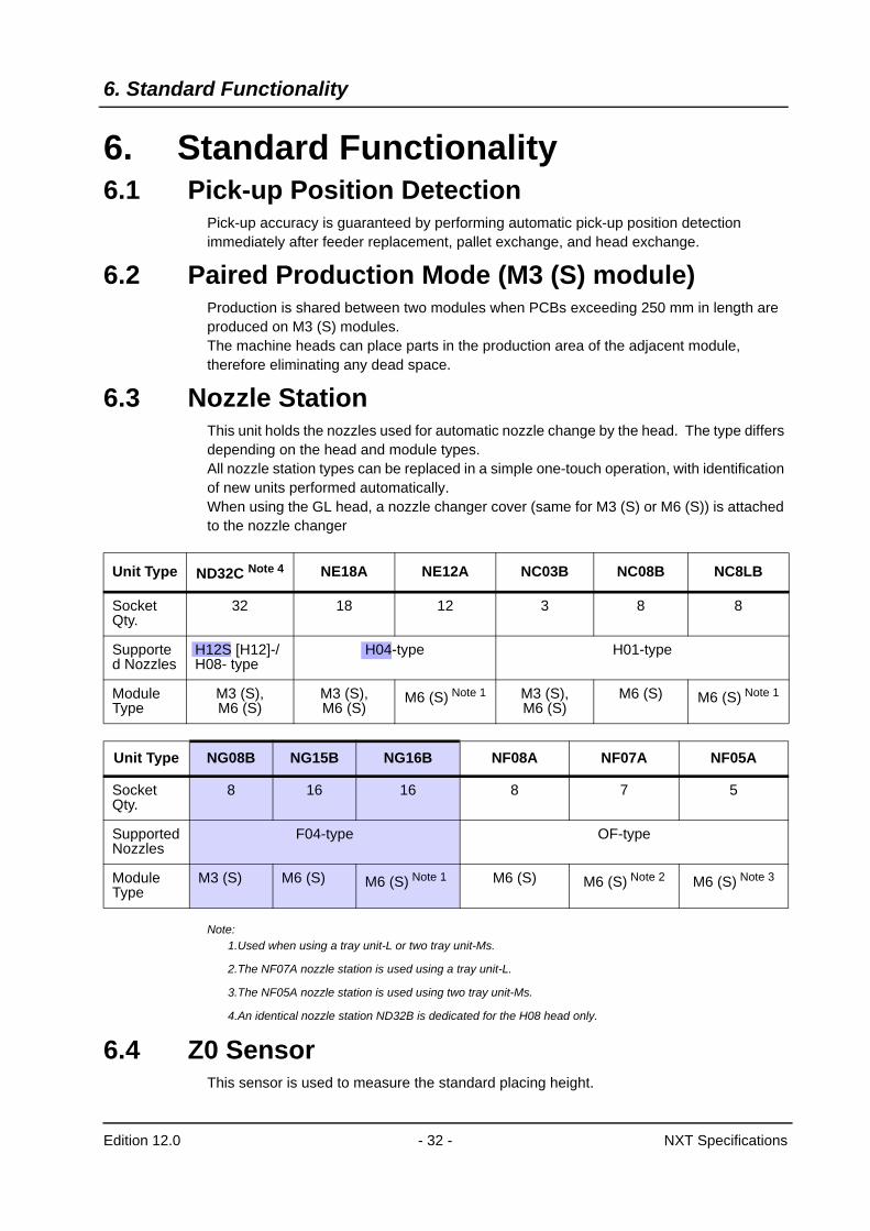
6.3 Nozzle StationThis unit holds the nozzles used for automatic nozzle change by the head. The type differs depending on the head and module types.All nozzle station types can be replaced in a simple one-touch operation, with identification of new units performed automatically.When using the GL head, a nozzle changer cover (same for M3 (S) or M6 (S)) is attached to the nozzle changer
Note:1.Used when using a tray unit-L or two tray unit-Ms.
2.The NF07A nozzle station is used using a tray unit-L.
3.The NF05A nozzle station is used using two tray unit-Ms.
4.An identical nozzle station ND32B is dedicated for the H08 head only.
6.4 Z0 SensorThis sensor is used to measure the standard placing height.
Unit Type ND32C Note 4 NE18A NE12A NC03B NC08B NC8LB
Socket Qty.
32 18 12 3 8 8
Supported Nozzles
H12S [H12]-/H08- type
H04-type H01-type
Module Type
M3 (S), M6 (S)
M3 (S), M6 (S)
M6 (S) Note 1 M3 (S), M6 (S)
M6 (S) M6 (S) Note 1
Unit Type NG08B NG15B NG16B NF08A NF07A NF05A
Socket Qty.
8 16 16 8 7 5
Supported Nozzles
F04-type OF-type
Module Type
M3 (S) M6 (S) M6 (S) Note 1 M6 (S) M6 (S) Note 2 M6 (S) Note 3
6. Standard Functionality
Edition 12.0 - 33 - NXT Specifications
6.5 Auto CalibrationThis function enables automatic placing accuracy compensation.Dedicated jig nozzles are required to use this function.An H12S [H12] head: 12 nozzles, H08 head: 8 nozzles, H04 head: 4 nozzles, F04 head: 4 nozzles, and OF head and H01 head: 1 nozzle is required for one module.
6.6 Placing Pressure ControlThis function is used to control the force applied to parts and is available only for the H01 head. (Control range: 2.2 to 9.8 N)
Note: NXT machine control software V3.10 or later is required to use the placing pressure control function.
6.7 Pressure Insertion PlacementThis function is used to support parts that require placement using pressure insertion. Only H01 and OF heads can used this function. Supported range: 39.2 to 98N for H01 and OF heads.
7. Options
Edition 12.0 - 34 - NXT Specifications
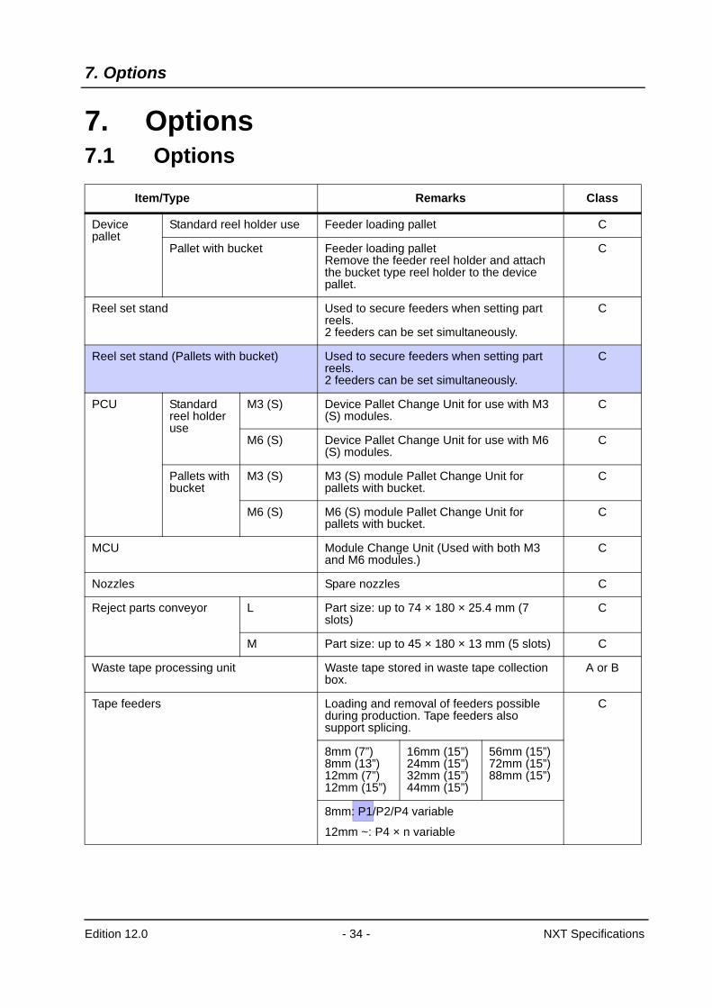
7. Options7.1 Options
Item/Type Remarks Class
Device pallet
Standard reel holder use Feeder loading pallet C
Pallet with bucket Feeder loading palletRemove the feeder reel holder and attach the bucket type reel holder to the device pallet.
C
Reel set stand Used to secure feeders when setting part reels.2 feeders can be set simultaneously.
C
Reel set stand (Pallets with bucket) Used to secure feeders when setting part reels.2 feeders can be set simultaneously.
C
PCU Standard reel holder use
M3 (S) Device Pallet Change Unit for use with M3 (S) modules.
C
M6 (S) Device Pallet Change Unit for use with M6 (S) modules.
C
Pallets with bucket
M3 (S) M3 (S) module Pallet Change Unit for pallets with bucket.
C
M6 (S) M6 (S) module Pallet Change Unit for pallets with bucket.
C
MCU Module Change Unit (Used with both M3 and M6 modules.)
C
Nozzles Spare nozzles C
Reject parts conveyor L Part size: up to 74 × 180 × 25.4 mm (7 slots)
C
M Part size: up to 45 × 180 × 13 mm (5 slots) C
Waste tape processing unit Waste tape stored in waste tape collection box.
A or B
Tape feeders Loading and removal of feeders possible during production. Tape feeders also support splicing.
C
8mm (7”)8mm (13”)12mm (7”)12mm (15”)
16mm (15”)24mm (15”)32mm (15”)44mm (15”)
56mm (15”)72mm (15”)88mm (15”)
8mm: P1/P2/P4 variable
12mm ~: P4 × n variable
7. Options
Edition 12.0 - 35 - NXT Specifications
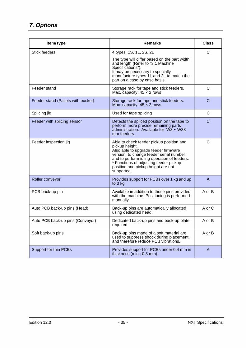
Stick feeders 4 types: 1S, 1L, 2S, 2L
The type will differ based on the part width and length (Refer to “3.1 Machine Specifications”).It may be necessary to specially manufacture types 1L and 2L to match the part on a case by case basis.
C
Feeder stand Storage rack for tape and stick feeders.Max. capacity: 45 × 2 rows
C
Feeder stand (Pallets with bucket) Storage rack for tape and stick feeders.Max. capacity: 45 × 2 rows
C
Splicing jig Used for tape splicing C
Feeder with splicing sensor Detects the spliced position on the tape to perform more precise remaining parts administration. Available for W8 ~ W88 mm feeders.
C
Feeder inspection jig Able to check feeder pickup position and pickup height.Also able to upgrade feeder firmware version, to change feeder serial number and to perform idling operation of feeders.* Functions of adjusting feeder pickup position and pickup height are not supported.
C
Roller conveyor Provides support for PCBs over 1 kg and up to 3 kg
A
PCB back-up pin Available in addition to those pins provided with the machine. Positioning is performed manually.
A or B
Auto PCB back-up pins (Head) Back-up pins are automatically allocated using dedicated head.
A or C
Auto PCB back-up pins (Conveyor) Dedicated back-up pins and back-up plate required.
A or B
Soft back-up pins Back-up pins made of a soft material are used to suppress shock during placement, and therefore reduce PCB vibrations.
A or B
Support for thin PCBs Provides support for PCBs under 0.4 mm in thickness (min.: 0.3 mm)
A
Item/Type Remarks Class
7. Options
Edition 12.0 - 36 - NXT Specifications
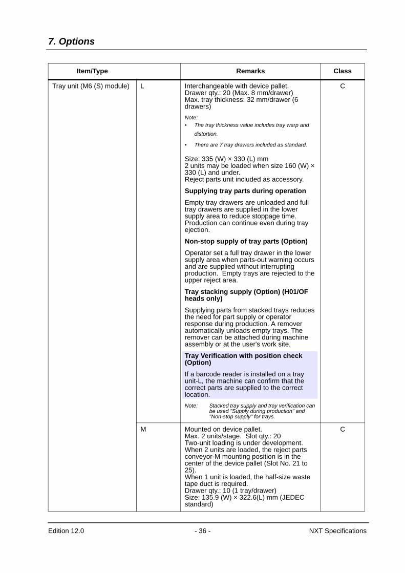
Tray unit (M6 (S) module) L Interchangeable with device pallet.Drawer qty.: 20 (Max. 8 mm/drawer)Max. tray thickness: 32 mm/drawer (6 drawers)Note:• The tray thickness value includes tray warp and
distortion.
• There are 7 tray drawers included as standard.
Size: 335 (W) × 330 (L) mm2 units may be loaded when size 160 (W) × 330 (L) and under.Reject parts unit included as accessory.
Supplying tray parts during operationEmpty tray drawers are unloaded and full tray drawers are supplied in the lower supply area to reduce stoppage time. Production can continue even during tray ejection.
Non-stop supply of tray parts (Option)Operator set a full tray drawer in the lower supply area when parts-out warning occurs and are supplied without interrupting production. Empty trays are rejected to the upper reject area.
Tray stacking supply (Option) (H01/OF heads only)Supplying parts from stacked trays reduces the need for part supply or operator response during production. A remover automatically unloads empty trays. The remover can be attached during machine assembly or at the user's work site.
Tray Verification with position check (Option)If a barcode reader is installed on a tray unit-L, the machine can confirm that the correct parts are supplied to the correct location.Note: Stacked tray supply and tray verification can
be used "Supply during production" and "Non-stop supply" for trays.
C
M Mounted on device pallet.Max. 2 units/stage. Slot qty.: 20Two-unit loading is under development.When 2 units are loaded, the reject parts conveyor-M mounting position is in the center of the device pallet (Slot No. 21 to 25).When 1 unit is loaded, the half-size waste tape duct is required.Drawer qty.: 10 (1 tray/drawer)Size: 135.9 (W) × 322.6(L) mm (JEDEC standard)
C
Item/Type Remarks Class
7. Options
Edition 12.0 - 37 - NXT Specifications
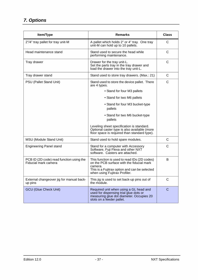
2”/4” tray pallet for tray unit-M A pallet which holds 2” or 4” tray. One tray unit-M can hold up to 10 pallets.
C
Head maintenance stand Stand used to secure the head while performing maintenance.
C
Tray drawer Drawer for the tray unit-L.Set the parts tray in the tray drawer and load the drawer into the tray unit-L.
C
Tray drawer stand Stand used to store tray drawers. (Max.: 21) C
PSU (Pallet Stand Unit) Stand used to store the device pallet. There are 4 types.
• Stand for four M3 pallets
• Stand for two M6 pallets
• Stand for four M3 bucket-type pallets
• Stand for two M6 bucket-type pallets
Leveling sheet specification is standard. Optional caster type is also available (more floor space is required than standard type).
C
MSU (Module Stand Unit) Stand used to hold spare modules. C
Engineering Panel stand Stand for a computer with Accessory Software, Fuji Flexa and other NXT software. Casters are attached.
C
PCB ID (2D code) read function using the Fiducial mark camera
This function is used to read IDs (2D codes) on the PCB surface with the fiducial mark camera.This is a Fujitrax option and can be selected when using Fujitrax Profiler.
B
External changeover jig for manual back-up pins
This jig is used to set back-up pins out of the module.
C
GCU (Glue Check Unit) Required unit when using a GL head and used for dispensing trial glue dots or measuring glue dot diameter. Occupies 20 slots on a feeder pallet.
C
Item/Type Remarks Class
7. Options
Edition 12.0 - 38 - NXT Specifications
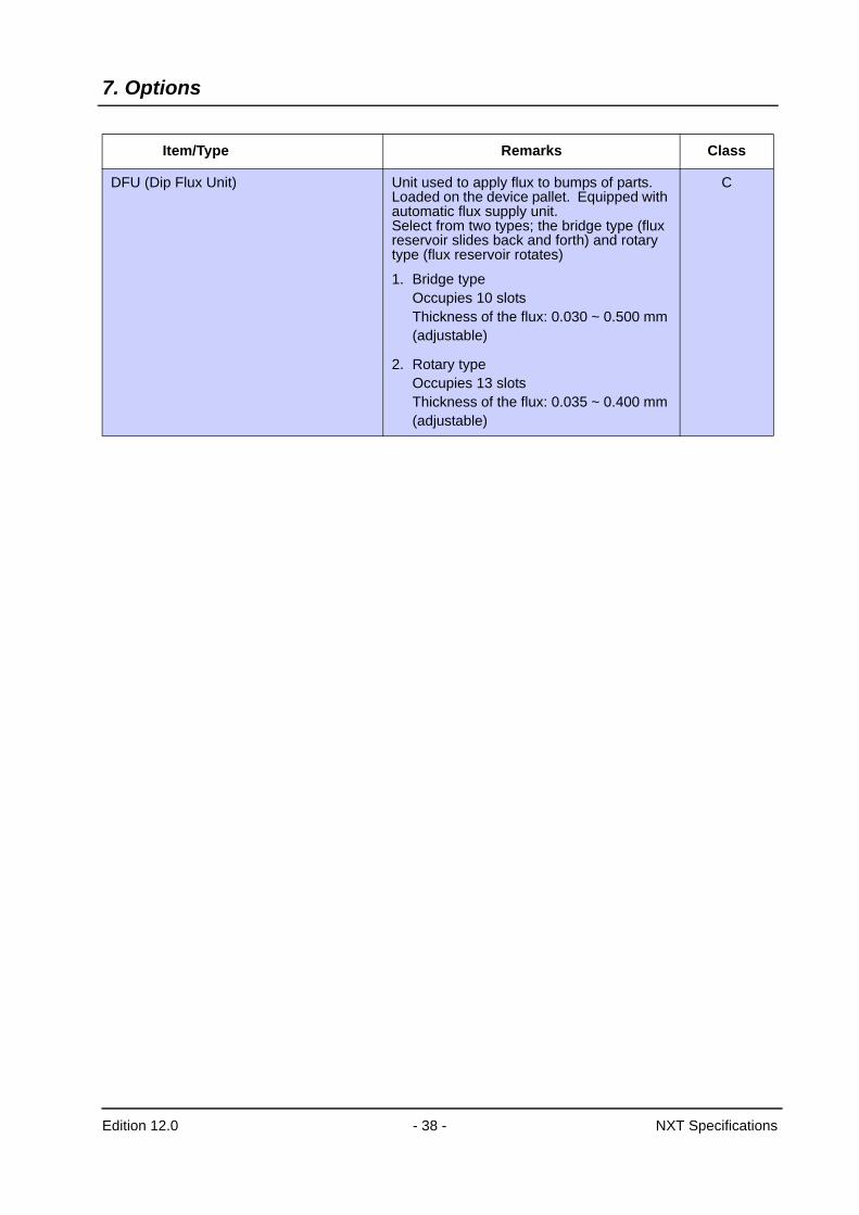
DFU (Dip Flux Unit) Unit used to apply flux to bumps of parts. Loaded on the device pallet. Equipped with automatic flux supply unit.Select from two types; the bridge type (flux reservoir slides back and forth) and rotary type (flux reservoir rotates)
1. Bridge typeOccupies 10 slotsThickness of the flux: 0.030 ~ 0.500 mm (adjustable)
2. Rotary typeOccupies 13 slotsThickness of the flux: 0.035 ~ 0.400 mm (adjustable)
C
Item/Type Remarks Class
7. Options
Edition 12.0 - 39 - NXT Specifications
A: Installed during machine assemblyB: On-site option installation possibleC: Supported with purchase of individual unit
Supplementary Notes:Please arrange a consultation with Fuji to discuss machine requirements other than
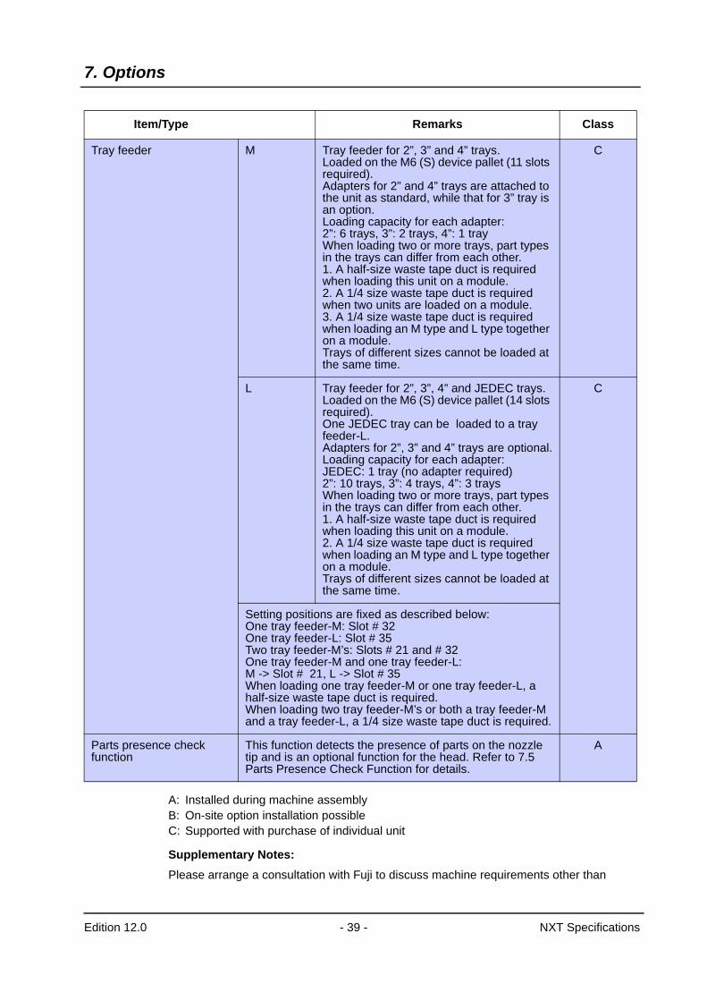
Tray feeder M Tray feeder for 2”, 3” and 4” trays. Loaded on the M6 (S) device pallet (11 slots required). Adapters for 2” and 4” trays are attached to the unit as standard, while that for 3” tray is an option.Loading capacity for each adapter: 2”: 6 trays, 3”: 2 trays, 4”: 1 trayWhen loading two or more trays, part types in the trays can differ from each other.1. A half-size waste tape duct is required when loading this unit on a module.2. A 1/4 size waste tape duct is required when two units are loaded on a module.3. A 1/4 size waste tape duct is required when loading an M type and L type together on a module.Trays of different sizes cannot be loaded at the same time.
C
L Tray feeder for 2”, 3”, 4” and JEDEC trays. Loaded on the M6 (S) device pallet (14 slots required). One JEDEC tray can be loaded to a tray feeder-L. Adapters for 2”, 3” and 4” trays are optional.Loading capacity for each adapter: JEDEC: 1 tray (no adapter required)2”: 10 trays, 3”: 4 trays, 4”: 3 traysWhen loading two or more trays, part types in the trays can differ from each other.1. A half-size waste tape duct is required when loading this unit on a module.2. A 1/4 size waste tape duct is required when loading an M type and L type together on a module.Trays of different sizes cannot be loaded at the same time.
C
Setting positions are fixed as described below:One tray feeder-M: Slot # 32One tray feeder-L: Slot # 35Two tray feeder-M’s: Slots # 21 and # 32One tray feeder-M and one tray feeder-L: M -> Slot # 21, L -> Slot # 35When loading one tray feeder-M or one tray feeder-L, a half-size waste tape duct is required.When loading two tray feeder-M’s or both a tray feeder-M and a tray feeder-L, a 1/4 size waste tape duct is required.
Parts presence check function
This function detects the presence of parts on the nozzle tip and is an optional function for the head. Refer to 7.5 Parts Presence Check Function for details.
A
Item/Type Remarks Class
7. Options
Edition 12.0 - 40 - NXT Specifications
provided in the standard specifications.
Please contact Fuji for further clarification regarding machine attachments other than those listed in the tables above.
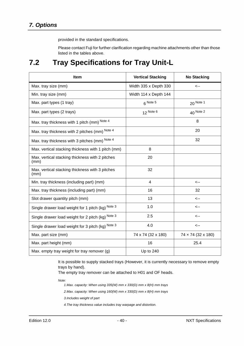
7.2 Tray Specifications for Tray Unit-L
It is possible to supply stacked trays (However, it is currently necessary to remove empty trays by hand).The empty tray remover can be attached to H01 and OF heads.
Note:1.Max. capacity: When using 335(W) mm x 330(D) mm x 8(H) mm trays
2.Max. capacity: When using 160(W) mm x 330(D) mm x 8(H) mm trays
3.Includes weight of part
4.The tray thickness value includes tray warpage and distortion.
Item Vertical Stacking No Stacking
Max. tray size (mm) Width 335 x Depth 330 <--
Min. tray size (mm) Width 114 x Depth 144
Max. part types (1 tray) 6 Note 5 20 Note 1
Max. part types (2 trays) 12 Note 6 40 Note 2
Max. tray thickness with 1 pitch (mm) Note 4 8
Max. tray thickness with 2 pitches (mm) Note 4 20
Max. tray thickness with 3 pitches (mm) Note 4 32
Max. vertical stacking thickness with 1 pitch (mm) 8
Max. vertical stacking thickness with 2 pitches (mm)
20
Max. vertical stacking thickness with 3 pitches (mm)
32
Min. tray thickness (including part) (mm) 4 <--
Max. tray thickness (including part) (mm) 16 32
Slot drawer quantity pitch (mm) 13 <--
Single drawer load weight for 1 pitch (kg) Note 3 1.0 <--
Single drawer load weight for 2 pitch (kg) Note 3 2.5 <--
Single drawer load weight for 3 pitch (kg) Note 3 4.0 <--
Max. part size (mm) 74 x 74 (32 x 180) 74 × 74 (32 x 180)
Max. part height (mm) 16 25.4
Max. empty tray weight for tray remover (g) Up to 240
7. Options
Edition 12.0 - 41 - NXT Specifications
5.Max. capacity: When using 335(W) x 330(D) x 32(Stacking height) mm trays.
6.Max. capacity: When using 160(W) x 330(D) s 32(Stacking height) mm trays.
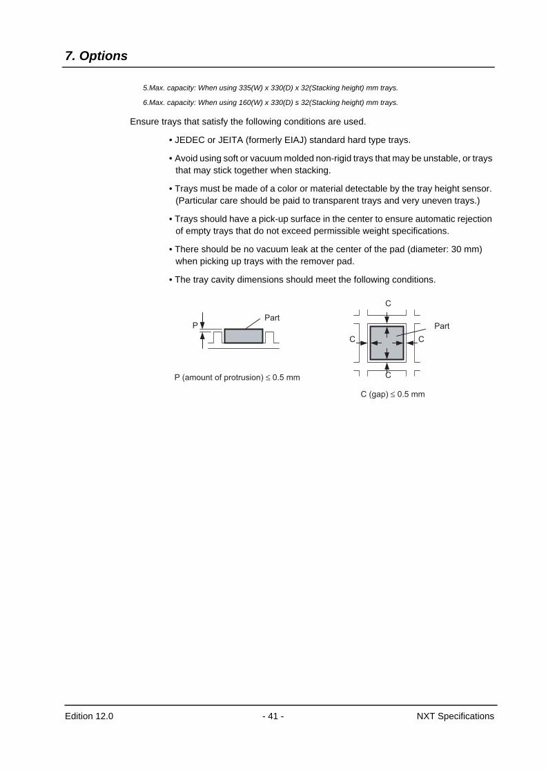
Ensure trays that satisfy the following conditions are used.
• JEDEC or JEITA (formerly EIAJ) standard hard type trays.
• Avoid using soft or vacuum molded non-rigid trays that may be unstable, or trays that may stick together when stacking.
• Trays must be made of a color or material detectable by the tray height sensor. (Particular care should be paid to transparent trays and very uneven trays.)
• Trays should have a pick-up surface in the center to ensure automatic rejection of empty trays that do not exceed permissible weight specifications.
• There should be no vacuum leak at the center of the pad (diameter: 30 mm) when picking up trays with the remover pad.
• The tray cavity dimensions should meet the following conditions.
P
C
C
C
C
PartPart
P (amount of protrusion) ≤ 0.5 mm
C (gap) ≤ 0.5 mm
7. Options
Edition 12.0 - 42 - NXT Specifications
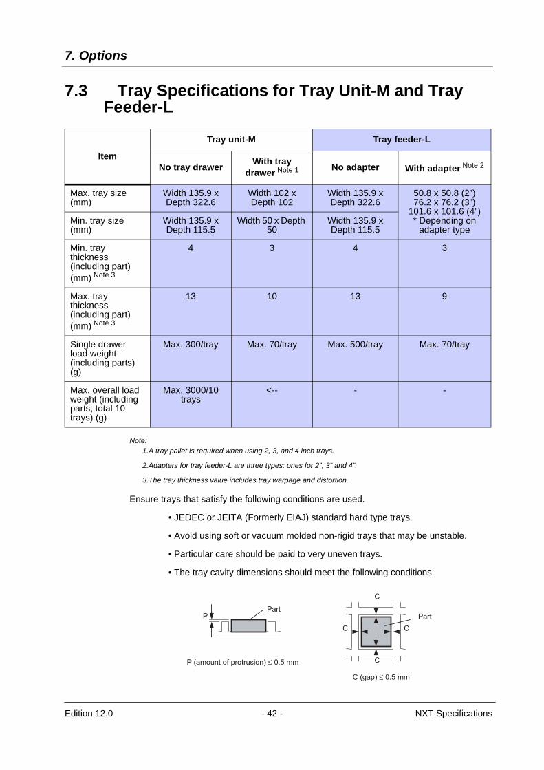
7.3 Tray Specifications for Tray Unit-M and Tray Feeder-L
Note:1.A tray pallet is required when using 2, 3, and 4 inch trays.
2.Adapters for tray feeder-L are three types: ones for 2”, 3” and 4”.
3.The tray thickness value includes tray warpage and distortion.
Ensure trays that satisfy the following conditions are used.
• JEDEC or JEITA (Formerly EIAJ) standard hard type trays.
• Avoid using soft or vacuum molded non-rigid trays that may be unstable.
• Particular care should be paid to very uneven trays.
• The tray cavity dimensions should meet the following conditions.
Item
Tray unit-M Tray feeder-L
No tray drawer With tray drawer Note 1 No adapter With adapter Note 2
Max. tray size (mm)
Width 135.9 x Depth 322.6
Width 102 x Depth 102
Width 135.9 x Depth 322.6
50.8 x 50.8 (2”)76.2 x 76.2 (3”)
101.6 x 101.6 (4”)* Depending on
adapter typeMin. tray size (mm)
Width 135.9 x Depth 115.5
Width 50 x Depth 50
Width 135.9 x Depth 115.5
Min. tray thickness (including part) (mm) Note 3
4 3 4 3
Max. tray thickness (including part) (mm) Note 3
13 10 13 9
Single drawer load weight (including parts) (g)
Max. 300/tray Max. 70/tray Max. 500/tray Max. 70/tray
Max. overall load weight (including parts, total 10 trays) (g)
Max. 3000/10 trays
<-- - -
P
C
C
C
C
PartPart
P (amount of protrusion) ≤ 0.5 mm
C (gap) ≤ 0.5 mm
7. Options
Edition 12.0 - 43 - NXT Specifications
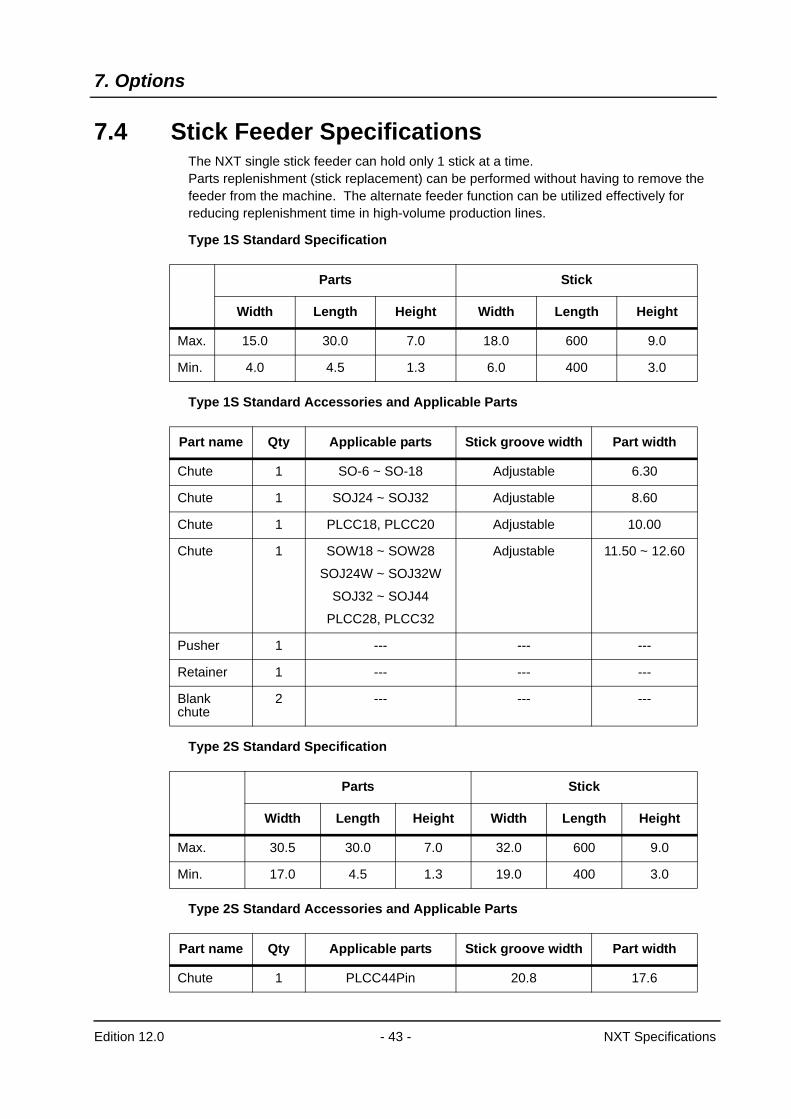
7.4 Stick Feeder SpecificationsThe NXT single stick feeder can hold only 1 stick at a time.Parts replenishment (stick replacement) can be performed without having to remove the feeder from the machine. The alternate feeder function can be utilized effectively for reducing replenishment time in high-volume production lines.
Type 1S Standard Specification
Type 1S Standard Accessories and Applicable Parts
Type 2S Standard Specification
Type 2S Standard Accessories and Applicable Parts
Parts Stick
Width Length Height Width Length Height
Max. 15.0 30.0 7.0 18.0 600 9.0
Min. 4.0 4.5 1.3 6.0 400 3.0
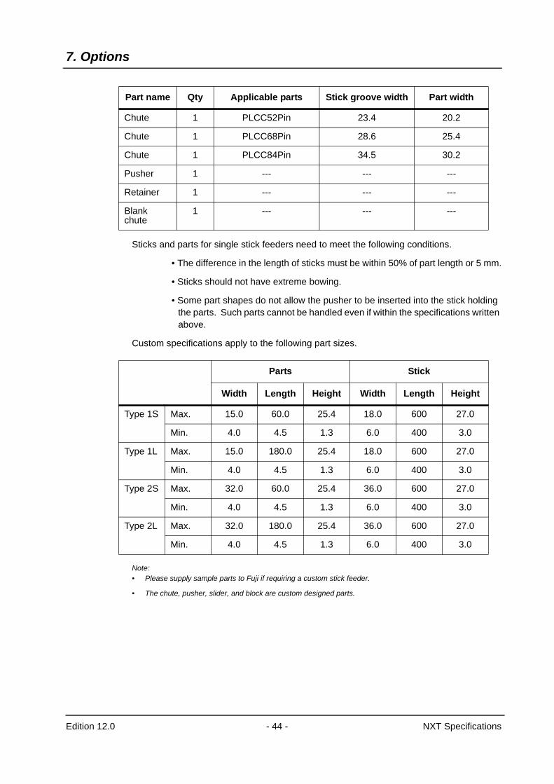
Part name Qty Applicable parts Stick groove width Part width
Chute 1 SO-6 ~ SO-18 Adjustable 6.30
Chute 1 SOJ24 ~ SOJ32 Adjustable 8.60
Chute 1 PLCC18, PLCC20 Adjustable 10.00
Chute 1 SOW18 ~ SOW28
SOJ24W ~ SOJ32W
SOJ32 ~ SOJ44
PLCC28, PLCC32
Adjustable 11.50 ~ 12.60
Pusher 1 --- --- ---
Retainer 1 --- --- ---
Blank chute
2 --- --- ---
Parts Stick
Width Length Height Width Length Height
Max. 30.5 30.0 7.0 32.0 600 9.0
Min. 17.0 4.5 1.3 19.0 400 3.0
Part name Qty Applicable parts Stick groove width Part width
Chute 1 PLCC44Pin 20.8 17.6
7. Options
Edition 12.0 - 44 - NXT Specifications
Sticks and parts for single stick feeders need to meet the following conditions.
• The difference in the length of sticks must be within 50% of part length or 5 mm.
• Sticks should not have extreme bowing.
• Some part shapes do not allow the pusher to be inserted into the stick holding the parts. Such parts cannot be handled even if within the specifications written above.
Custom specifications apply to the following part sizes.
Note:• Please supply sample parts to Fuji if requiring a custom stick feeder.
• The chute, pusher, slider, and block are custom designed parts.
Chute 1 PLCC52Pin 23.4 20.2
Chute 1 PLCC68Pin 28.6 25.4
Chute 1 PLCC84Pin 34.5 30.2
Pusher 1 --- --- ---
Retainer 1 --- --- ---
Blank chute
1 --- --- ---
Part name Qty Applicable parts Stick groove width Part width
Parts Stick
Width Length Height Width Length Height
Type 1S Max. 15.0 60.0 25.4 18.0 600 27.0
Min. 4.0 4.5 1.3 6.0 400 3.0
Type 1L Max. 15.0 180.0 25.4 18.0 600 27.0
Min. 4.0 4.5 1.3 6.0 400 3.0
Type 2S Max. 32.0 60.0 25.4 36.0 600 27.0
Min. 4.0 4.5 1.3 6.0 400 3.0
Type 2L Max. 32.0 180.0 25.4 36.0 600 27.0
Min. 4.0 4.5 1.3 6.0 400 3.0
7. Options
Edition 12.0 - 45 - NXT Specifications
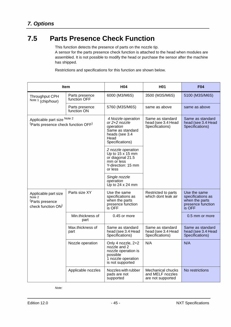
7.5 Parts Presence Check FunctionThis function detects the presence of parts on the nozzle tip.A sensor for the parts presence check function is attached to the head when modules are assembled. It is not possible to modify the head or purchase the sensor after the machine has shipped.
Restrictions and specifications for this function are shown below.
Note:
Item H04 H01 F04
Throughput CPH Note 1 (chip/hour)
Parts presence function OFF
6000 (M3/M6S) 3500 (M3S/M6S) 5100 (M3S/M6S)
Parts presence function ON
5760 (M3S/M6S) same as above same as above
Applicable part size Note 2 (Parts presence check function OFF)
4 Nozzle operation or 2+2 nozzle operationSame as standard heads (see 3.4 Head Specifications)
Same as standard head (see 3.4 Head Specifications)
Same as standard head (see 3.4 Head Specifications)
2 nozzle operationUp to 15 x 15 mm or diagonal 21.5 mm or less Y-direction: 15 mm or less
Single nozzle operation Up to 24 x 24 mm
Applicable part size Note 2 (Parts presence check function ON)
Parts size XY Use the same specifications as when the parts presence function is OFF
Restricted to parts which dont leak air
Use the same specifications as when the parts presence function is OFF
Min.thickness of part
0.45 or more 0.5 mm or more
Max.thickness of part
Same as standard head (see 3.4 Head Specifications)
Same as standard head (see 3.4 Head Specifications)
Same as standard head (see 3.4 Head Specifications)
Nozzle operation Only 4 nozzle, 2+2 nozzle and 2 nozzle operation is possible1 nozzle operation is not supported
N/A N/A
Applicable nozzles Nozzles with rubber pads are not supported
Mechanical chucks and MELF nozzles are not supported
No restrictions
7. Options
Edition 12.0 - 46 - NXT Specifications
1.The value for throughput is the value measured under Fuji conditions..
2.The applicable part size which can be used with a head which has the parts presence detection sensor.
3.Glass parts used for placing accuracy measurement (PAM) cannot be detected.
8. NXT Related Software
Edition 12.0 - 44 - NXT Specifications
8. NXT Related Software8.1 NXT Accessory Software
This is a stand alone piece of software providing machine control capabilities.All machine settings are performed using this software. Furthermore, it provides the user with a powerful tool when performing maintenance and inspections.The main features of the NXT Accessory Software are as follows.
• Data management
• Data editing
• Maintenance support
Note: A separate computer is required for installation of the NXT Accessory Software.
8.2 FujitraxThis system has been designed to realize maximum levels of control for parts loaded on machines in the SMT line, and whose wide range of features include remaining parts administration, and acquisition of reel parts quantity information, feeder related information, and also device slot information from the production program.By linking with NXT Fuji intelligent feeders, Fujitrax is able to eliminate part misloading, provide parts out warnings, perform feeder administration, and also prevent defective PCBs and enhance productivity.Furthermore, it is possible to prevent the occurrence of defective PCBs by acquiring traceability data for each PCB.Fujitrax software and hardware are available separately.
Fujitrax: Traceable Realtime Administration
<Dynamic Alternate Feeder>It is possible to arbitrarily set alternate feeders on empty slots on the feeder pallet when using Fujitrax, therefore dispensing with the need to prepare multiple empty slots for alternate feeders and set alternate feeder positions in the program as was required previously. Furthermore, this enables uninterrupted operation without performing splicing, and prevents the operator mistakenly splicing the wrong part.
<Tray Part Non-Stop Supply (Tray Unit-L)>If the Fujitrax system is adopted, and supply parts are set on the drawer area below tray unit-L, tray parts are automatically fed following parts out based on parts out warnings, enabling continuous tray part supply without stopping the machine.
< Free Feeder Allocation Function>When using Fujitrax, it is possible to commence production even though the parts allocation on certain modules differs from that set in the production program.As a result, provided that the parts required for that module are prepared in advance, they can be freely allocated to any slot.However, it is not possible to freely allocate parts to different modules.Furthermore, it is not possible to use this function together with the dynamic alternate feeder function described above.
8. NXT Related Software
Edition 12.0 - 45 - NXT Specifications
<Main Functions Enabled by Adopting Fujitrax>• Incorrect part loading prevention function
• Parts out warning function
• PCB traceability data acquisition
• PCB ID (2D code) read function using the NXT fiducial mark camera
Note: Please refer to the “Fujitrax Specifications” for further details on Fujitrax specifications.
8. NXT Related Software
Edition 12.0 - 46 - NXT Specifications
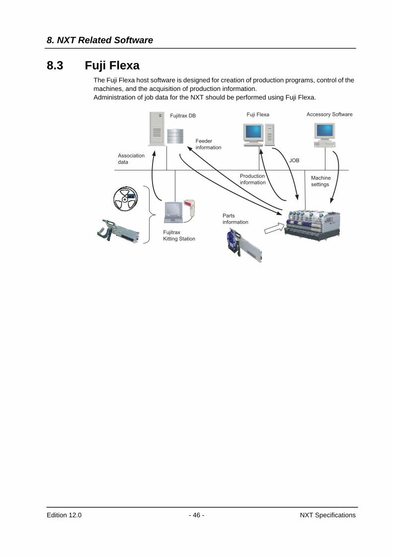
8.3 Fuji FlexaThe Fuji Flexa host software is designed for creation of production programs, control of the machines, and the acquisition of production information. Administration of job data for the NXT should be performed using Fuji Flexa.
JOB
Accessory SoftwareFuji FlexaFujitrax DB
Association
data
Fujitrax
Kitting Station
Parts
information
Machine
settings
Production
information
Feeder
information

9. Module Configuration
Edition 12.0 - 47 - NXT Specifications
9. Module Configuration9.1 Module Configuration9.1.1 M3 (S) Module Configuration
Standard Units
Module (M3 (S))
XY-robot (M3 (S))
Cover (M3 (S))
Parts camera Mark camera
Reject parts box
Configurable Units
Main conveyor Double conveyor
Single conveyor
Standard conveyor
Roller conveyor
Thin PCB support conveyor
Waste tape processing unit Feeders Nozzles Reject parts conveyor
Back-up plate
Double conveyor use
Single conveyor use
Standard back-up pin/
Auto back-up pin use
Device pallet 20 slot pallet
H08H12S [H12] H04 H01Head
Nozzle station H12S [H12]/H08 use H01 use (M3 (S))
F04 GL
F04 use (M3 (S))
Optional Units
Auto back-up pins
DFU (Dip flux unit)
GCU (Glue check unit)
H04 use (M3 (S))
9. Module Configuration
Edition 12.0 - 48 - NXT Specifications
9.1.2 M6 (S) Module Configuration
Standard Units
Module (M6 (S))
XY-robot (M6 (S))
Cover (M6 (S))
Parts camera
Mark camera
Configurable Units
Main conveyor
Double conveyor
Single conveyor
Single conveyor S (M6S)
Standard conveyor
Roller conveyor
Thin PCB support conveyor
Optional Units
Waste tape processing unit Feeders Nozzles Reject parts conveyor
Back-up plate
Double conveyor use
Single conveyor use
Standard back-up pin /
Auto back-up pin use
Device pallet 45 slot pallet Tray unit-L
H08 H12S [H12] Placing head
Nozzle station H12S [H12]/H08 use
F04 use (M6 (S))
H04 use (Tray unit-L use)
H01 use (M6 (S))
F04 use (Tray unit-L use)
Standard camera
Sidelight camera
Tray unit-M
H04 H01 F04 OF GL
H04 use(M6 (S))
H01 use (Tray unit-L use)
OF use (M6 (S))
OF use (Tray unit-L use) OF use (Tray unit-M x 2 use)
Auto back-up pin GCU (Glue check unit)
DFU (Dip flux unit) Tray feeder-L Tray feeder-M
10. Peripheral Equipment
Edition 12.0 - 49 - NXT Specifications
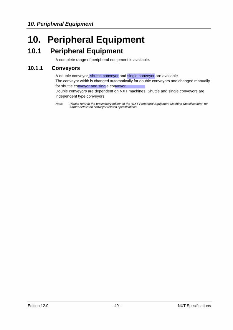
10. Peripheral Equipment10.1 Peripheral Equipment
A complete range of peripheral equipment is available.
10.1.1 ConveyorsA double conveyor, shuttle conveyor and single conveyor are available.The conveyor width is changed automatically for double conveyors and changed manually for shuttle conveyor and single conveyor.Double conveyors are dependent on NXT machines. Shuttle and single conveyors are independent type conveyors.
Note: Please refer to the preliminary edition of the “NXT Peripheral Equipment Machine Specifications” for further details on conveyor related specifications.
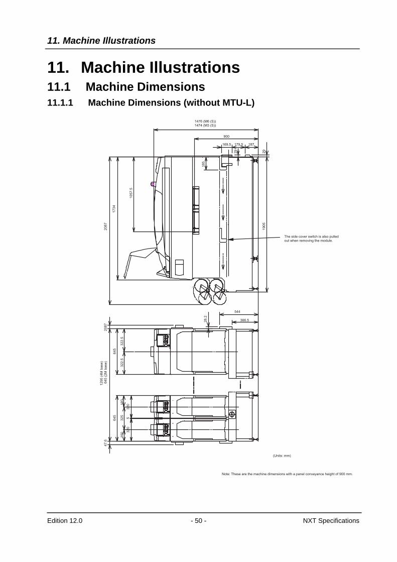
11. Machine Illustrations
Edition 12.0 - 50 - NXT Specifications
11. Machine Illustrations11.1 Machine Dimensions11.1.1 Machine Dimensions (without MTU-L)
1476 (M6 (S))1474 (M3 (S))
900
169.5 179.5 187
29
29
19
05
20
87
12
95
(4
M b
ase
)
64
5 (
2M
ba
se
)2
08
7
28
.2
47
.6
64
56
45
32
53
22
.53
22
.5
53
20
32
016
01
60
10
57
.5
17
34
18
5
544
366.5
The side cover switch is also pulledout when removing the module.
(Units: mm)
Note: These are the machine dimensions with a panel conveyance height of 900 mm.
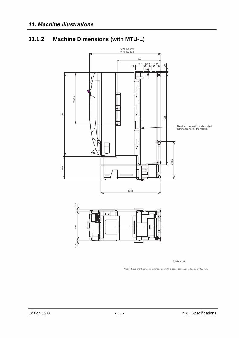
11. Machine Illustrations
Edition 12.0 - 51 - NXT Specifications
11.1.2 Machine Dimensions (with MTU-L)1476 (M6 (S))1474 (M3 (S))
1243
900
169.5 179.5 187
29
29
19
05
77
3.5
The side cover switch is also pulled out when removing the module.
46
01
734
10
57.5
18
.55
95
31
.5
(Units: mm)
Note: These are the machine dimensions with a panel conveyance height of 900 mm.
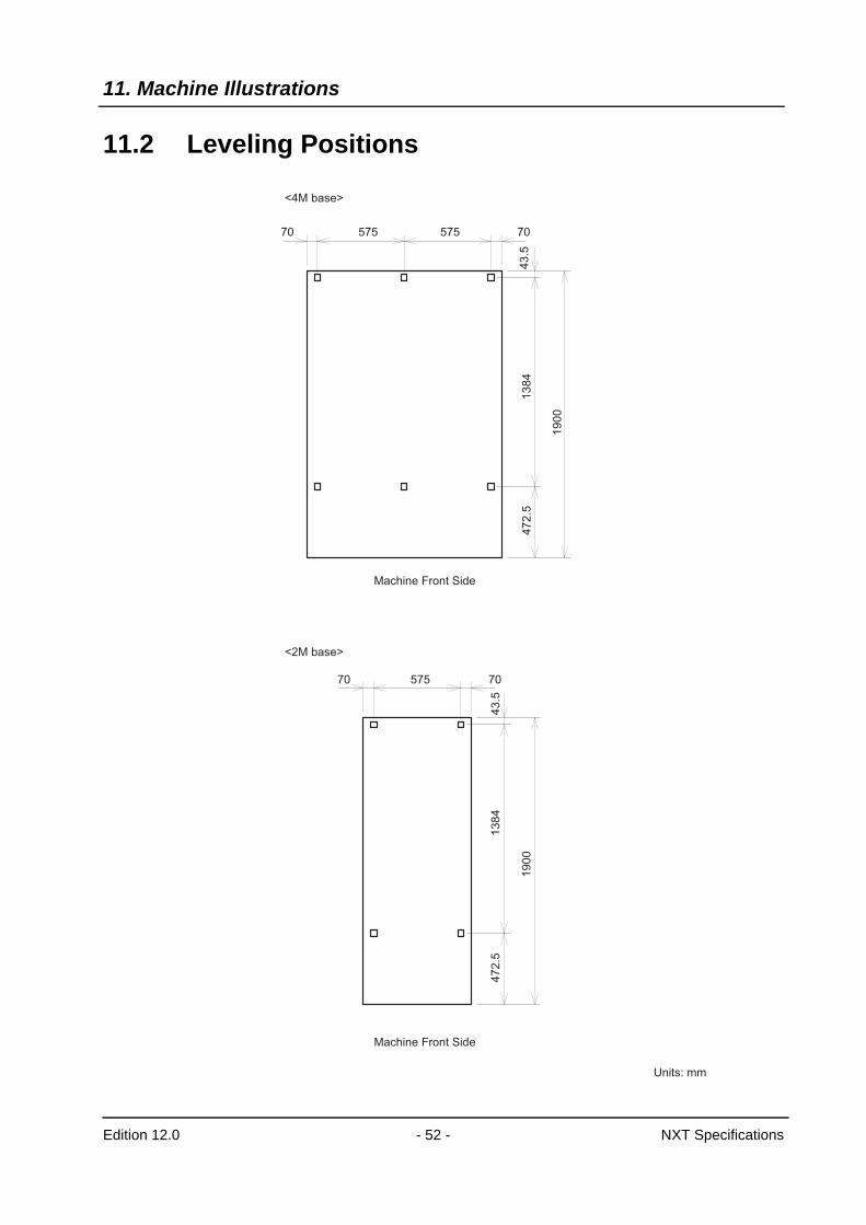
11. Machine Illustrations
Edition 12.0 - 52 - NXT Specifications
11.2 Leveling Positions
70 575
1384
19
00
47
2.5
575 70
70 575
43
.5
43
.5
1384
19
00
47
2.5
70
Machine Front Side
Machine Front Side
<4M base>
<2M base>
Units: mm
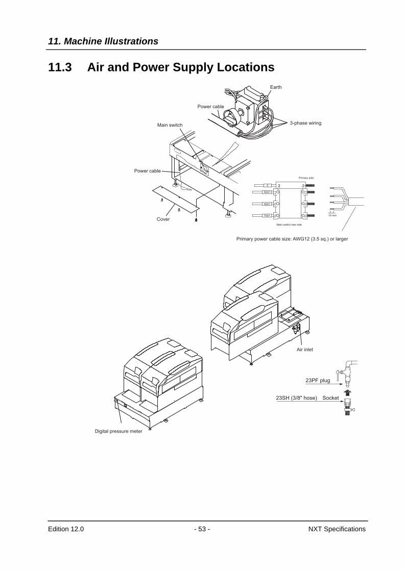
11. Machine Illustrations
Edition 12.0 - 53 - NXT Specifications
11.3 Air and Power Supply LocationsEarth
3-phase wiring
Power cable
Power cable
Main switch
CoverMain switch rear side
E
PE
PE
T1
T1
T2
T2
T3
T3
R001
S001
T001
Primary side
10 mm
Primary power cable size: AWG12 (3.5 sq.) or larger
Digital pressure meter
Air inlet
23PF plug
23SH (3/8" hose) Socket
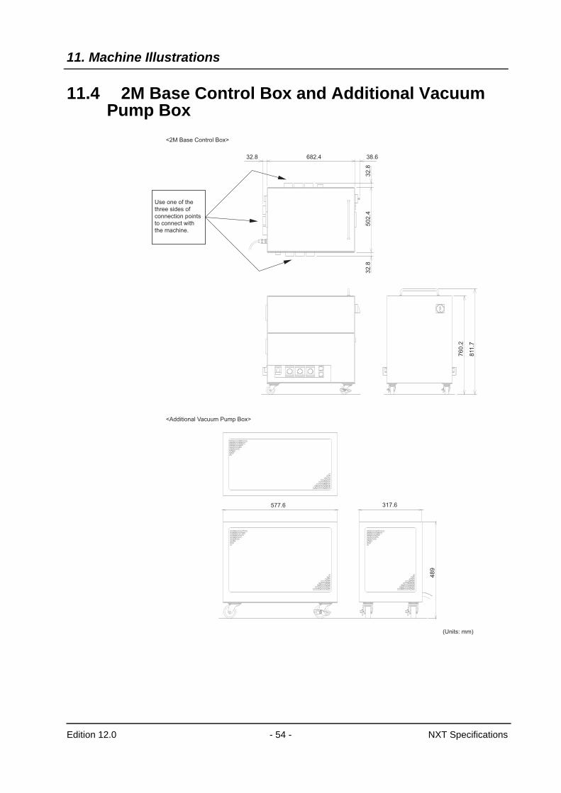
11. Machine Illustrations
Edition 12.0 - 54 - NXT Specifications
11.4 2M Base Control Box and Additional Vacuum Pump Box
Use one of the
three sides of
connection points
to connect with
the machine.
32.8 682.4 38.6
32
.850
2.4
32
.8
76
0.2
811
.7
317.6
48
9
577.6
<2M Base Control Box>
<Additional Vacuum Pump Box>
(Units: mm)

The FUJI InternetFuji Internet aims at providing up-to-date information to our customers in themost efficient manner. This site makes a range of services available, frommanual updates and virtual training, to online technical reports. Fuji hopes thatthis site will be used as a source of information in addition to the servicesprovided by your agent. Fuji Internet is located at http://www.fuji.co.jp/Fuji Internet membership is required to access the Technical Information sectionof the site. Please contact your agent for membership details. Any comments or opinions regarding this document can be sent to [email protected]
For inquiries concerning this specifications please contact Fuji at one of the offices listed below.
Headquarters Fuji Machine Manufacturing Co., Ltd.
19 Chausuyama Yamamachi, Chiryu, Aichi, 472-8686 JapanTel: (0566) 81 - 2110Fax: (0566) 83 - 1140
Overseas Offices Fuji America Corporation
171 Corporate Woods Parkway Vernon Hills, IL. 60061 USATel: (847) 913-0162 Fax: (847) 913-0186
Fuji Machine Mfg. (Europe) GmbHPeter-Sander-Str. 43 D-55252 Mainz-Kastel GermanyTel: 06134-202120 Fax: 06134-202200
Fuji do Brasil Maquinas Industriais Ltda.Rua Joao Cachoeira, 128 Itaim Bibi, Sao Paulo, SP 04535-000 BrazilTel: 55-11-3167 1650 Fax: 55-11-3079 1833
Fuji Machine Philippines, Inc.Warehouse 888 Don Mariano LimIndustrial Complex (La Fuerza Compound) Alabang, Zapote Rd.,Almanza Uno Las Pinas City, PhilippinesTel: (02) 809-4565 Fax: (02) 807-2767
Fuji Machine Mfg. (Singapore) Pte Ltd.Blk 2/51, Ubi Avenue 1, #01-24, Paya Ubi Industrial Park, Singapore 408933Tel: 65-7464966 Fax: 65-8412326
Fuji Malaysia OfficeC/O Mecomb Malaysia Sdn Bhd 2487, Jalan Sultan Azlan Shah 11700 Penang, MalaysiaTel: (04) 656-4002 Fax: (04) 656-2941
Fuji Taiwan OfficeC/O Ascentex Industry Corp.3 FL, No. 396, Sec. 1, Nei Hu Rd., Taipei, Taiwan R.O.C.Tel: (02) 8797-8716 Fax: (02) 8797-8717
Fuji Machine Mfg. Co., Ltd. China Representative OfficeRoom A, 26F, Zhaofeng World Trade Building, No. 369, Jiangsu Road, Shanghai, ChinaTel: (21) 5240-0730 Fax: (21) 5240-0728
Fuji Scalable Placement Platform NXT Machine SpecificationsEdition 1.0 October 26, 2004Edition 2.0 May 12, 2005Edition 3.0 June 28, 2005Edition 4.0 October 25, 2005Edition 5.0 January 16, 2006Edition 6.0 February 15, 2006Edition 7.0 February 16, 2006Edition 8.0 May 16, 2006Edition 9.0 May 23, 2006Edition 10.0 June 23, 2006Edition 11.0 August 25, 2006
Fuji Machine Manufacturing Co., Ltd.SMT Equipment19 Chausuyama, Yamamachi, Chiryu,Aichi Prefecture, 472-8686 Japan
The specifications are subject to change without notice.Copyright 2006 by Fuji Machine Manufacturing Co., Ltd.
is a trademark of Fuji Machine Manufacturing Co., Ltd., and registered in the followingcountries: Austria, Belgium, Denmark, Finland, France, Germany, Greece, Indonesia, Ireland, Italy, Japan, Korea,Luxembourg, the Netherlands, Portugal, Spain, Sweden, the U.K., and the U.S.A.Printed in Japan
R
NXT Machine Specifications
Revision History
Date of Issue Revision Number Items Contents of the Revision
October 18, 2006 CNT-NXT-12.0E Revised.
3.4Restrictions and diagonal part dimensions for 2 nozzle operation with the H04 head have been added.A row for pressure insertion placement has been deleted.The OF throughput has changed.
6.6 The range for placing pressure control was changed from 98N to 9.8N.
6.7 A new section for pressure insertion placement has been added.
7The adapter which is supplied as standard for the tray unit-M was changed from 2” or 4” to 2” only.Waste tape duct restrictions for the tray unit-M and L have been added.Details for the parts presence check function have been added.
7.5 Specifications for the parts presence check function have been added.
August 25, 2006 CNT-NXT-11.0E Revised.
3.4 Explanations for required units when using GL head were added to the note #13.
3.57.1 Maximum load for roller conveyor: 2 kg -> 3 kg
4.4 Back-up plate size for 50~165 mm was added to the table.
4.8.3 Condition for the loading feeders at the ends of a pallet was changed for W32 for slot #19 (44): 5 -> 4
7.1
PSU: explanations of two different specifications were added; the standard leveling sheet type and the optional caster type.DFU: explanations of two different specifications were added; the bridge type and the rotary type. The specification for the bridge type was changed.Feeder inspection jig was added.Feeder with splicing sensor was added.
June 23, 2006 CNT-NXT-10.0E Revised.
2.1 Power consumption: A table clarifying the values for independent bases and dependent bases was added.Recommended specifications for isolating transformer were added.
4.7 F04 head nozzles: 0.5 was deleted and 0.4 was added.
7.3 Tray unit-M with tray drawer: Width 102 x Depth 204 -> Width 102 x Depth 102
May 23, 2006 CNT-NXT-9.0E Revised.
3.1 “Note 5” was added to the table.
3.4 H08 bump parts size: 8.0 mm x 8.0 mm -> 7.5 mm x 7.5 mm
5.1 Maximum number of sequences when using Fujitrax Profiler was added.
7.1 Highlighting was removed from tape feeder W72/88.
May 16, 2006 CNT-NXT-8.0E The layout was substantially revised to match that of other machine types
Whole docu.
Highlighting was removed from M3S and M6S. The single conveyor S was highlighted. All highlighting was removed from notes for the tray remover and tray stacking.
Cover The cover design was changed.
T.O.C. Section titles were changed. Machine specifications to Specifications A note was added to the end of the table of contents.
1.2 The Features section was completely revised.
2.1 The layout of the Machine Data and Operating Environment section was changed. The air consumption amount was changed. A note was added regarding the color of the machine.
3.1 The layout was changed. Table notes for target parts and placing accuracy were changed. Notes were moved outside the table.
3.3 Highlighting was removed from item regarding the loading of 2 tray unit Ms.
3.4 "Double nozzle operation specifications" was added to Note 1 for the H04 head. An illustration was added. The OF head officially supports tray parts. Highlighting was removed from "tray"
4 An illustration (an overview diagram) was added for machine structure
4.7 The layout of the nozzle type chart was changed.
Date of Issue Revision Number Items Contents of the Revision
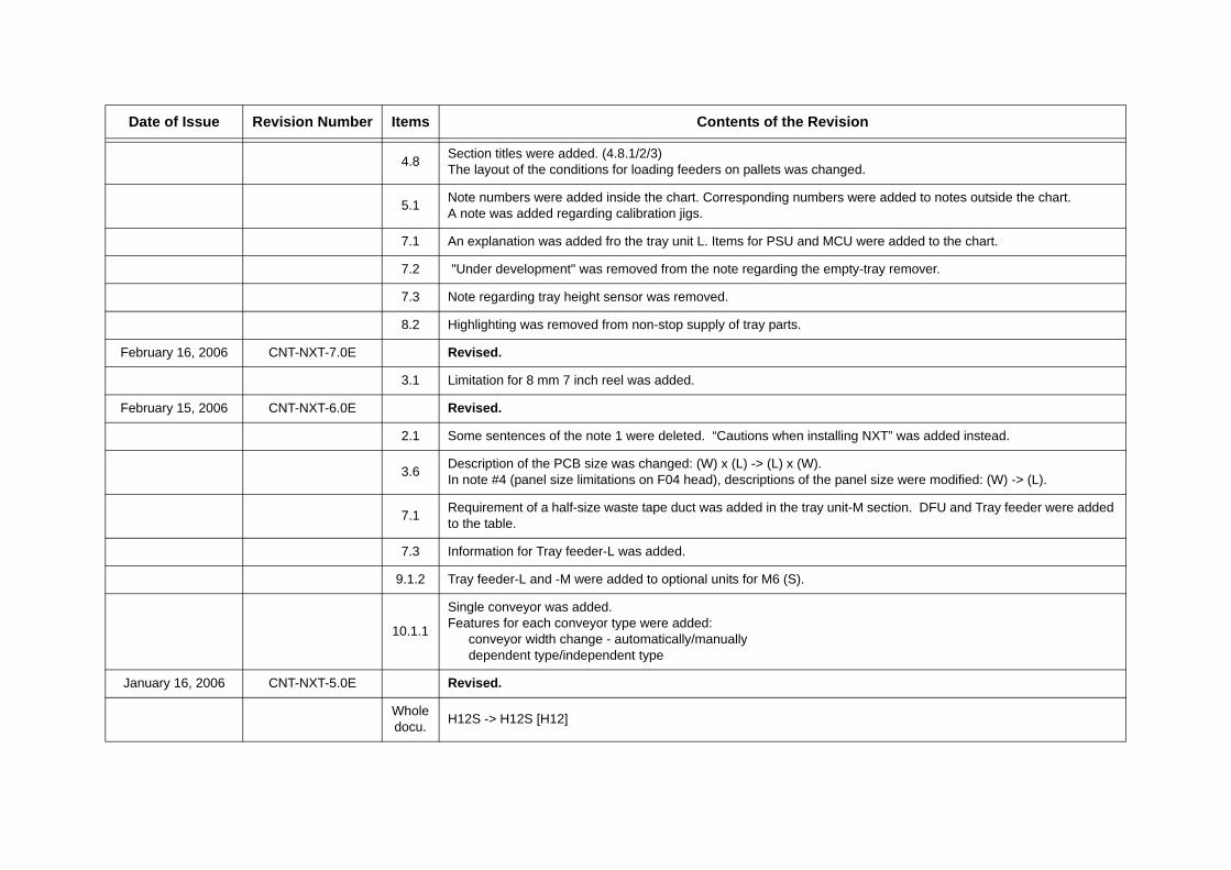
4.8 Section titles were added. (4.8.1/2/3) The layout of the conditions for loading feeders on pallets was changed.
5.1 Note numbers were added inside the chart. Corresponding numbers were added to notes outside the chart. A note was added regarding calibration jigs.
7.1 An explanation was added fro the tray unit L. Items for PSU and MCU were added to the chart.
7.2 "Under development" was removed from the note regarding the empty-tray remover.
7.3 Note regarding tray height sensor was removed.
8.2 Highlighting was removed from non-stop supply of tray parts.
February 16, 2006 CNT-NXT-7.0E Revised.
3.1 Limitation for 8 mm 7 inch reel was added.
February 15, 2006 CNT-NXT-6.0E Revised.
2.1 Some sentences of the note 1 were deleted. “Cautions when installing NXT” was added instead.
3.6 Description of the PCB size was changed: (W) x (L) -> (L) x (W).In note #4 (panel size limitations on F04 head), descriptions of the panel size were modified: (W) -> (L).
7.1 Requirement of a half-size waste tape duct was added in the tray unit-M section. DFU and Tray feeder were added to the table.
7.3 Information for Tray feeder-L was added.
9.1.2 Tray feeder-L and -M were added to optional units for M6 (S).
10.1.1
Single conveyor was added.Features for each conveyor type were added:
conveyor width change - automatically/manuallydependent type/independent type
January 16, 2006 CNT-NXT-5.0E Revised.
Whole docu. H12S -> H12S [H12]
Date of Issue Revision Number Items Contents of the Revision
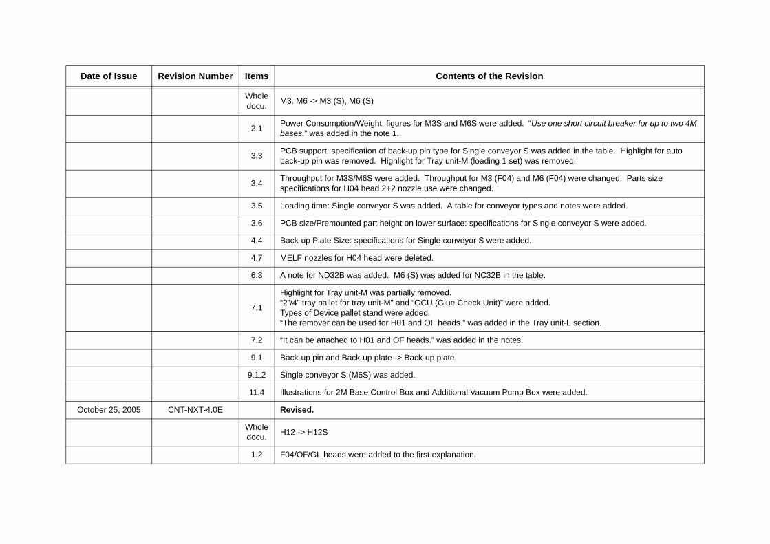
Whole docu. M3. M6 -> M3 (S), M6 (S)
2.1 Power Consumption/Weight: figures for M3S and M6S were added. “Use one short circuit breaker for up to two 4M bases.” was added in the note 1.
3.3 PCB support: specification of back-up pin type for Single conveyor S was added in the table. Highlight for auto back-up pin was removed. Highlight for Tray unit-M (loading 1 set) was removed.
3.4 Throughput for M3S/M6S were added. Throughput for M3 (F04) and M6 (F04) were changed. Parts size specifications for H04 head 2+2 nozzle use were changed.
3.5 Loading time: Single conveyor S was added. A table for conveyor types and notes were added.
3.6 PCB size/Premounted part height on lower surface: specifications for Single conveyor S were added.
4.4 Back-up Plate Size: specifications for Single conveyor S were added.
4.7 MELF nozzles for H04 head were deleted.
6.3 A note for ND32B was added. M6 (S) was added for NC32B in the table.
7.1
Highlight for Tray unit-M was partially removed.“2”/4” tray pallet for tray unit-M” and “GCU (Glue Check Unit)” were added.Types of Device pallet stand were added.“The remover can be used for H01 and OF heads.” was added in the Tray unit-L section.
7.2 “It can be attached to H01 and OF heads.” was added in the notes.
9.1 Back-up pin and Back-up plate -> Back-up plate
9.1.2 Single conveyor S (M6S) was added.
11.4 Illustrations for 2M Base Control Box and Additional Vacuum Pump Box were added.
October 25, 2005 CNT-NXT-4.0E Revised.
Whole docu. H12 -> H12S
1.2 F04/OF/GL heads were added to the first explanation.
Date of Issue Revision Number Items Contents of the Revision
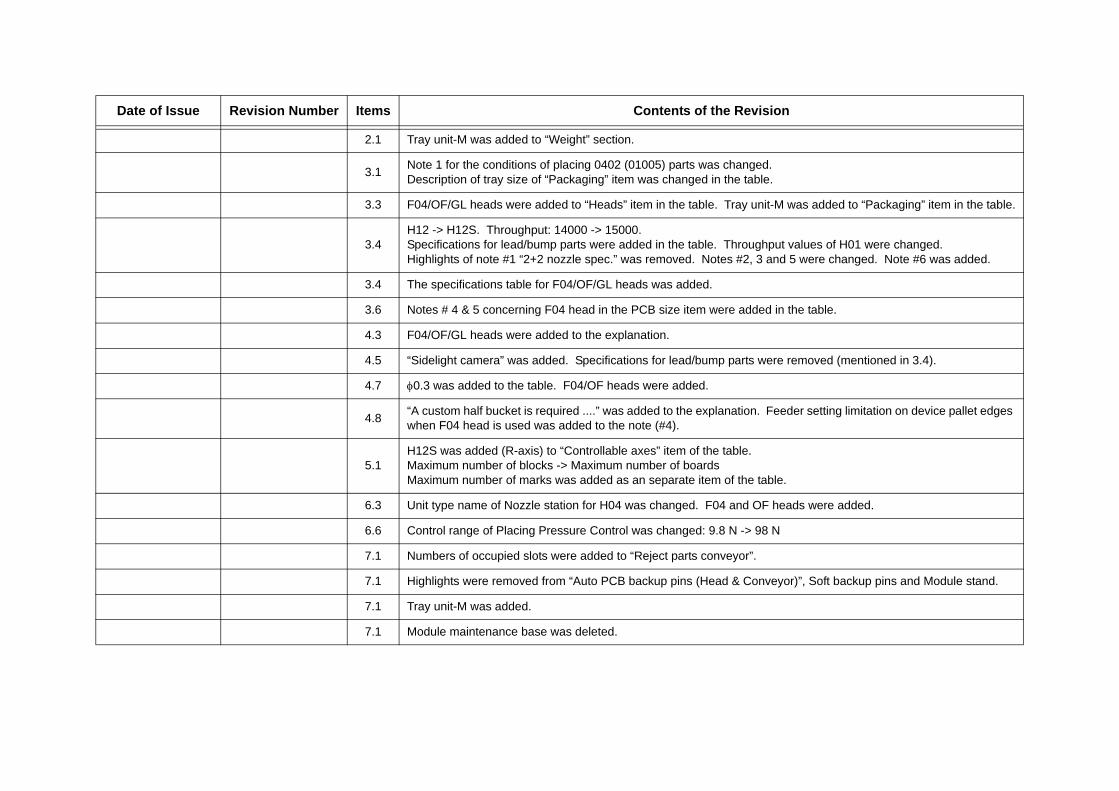
2.1 Tray unit-M was added to “Weight” section.
3.1 Note 1 for the conditions of placing 0402 (01005) parts was changed.Description of tray size of “Packaging” item was changed in the table.
3.3 F04/OF/GL heads were added to “Heads” item in the table. Tray unit-M was added to “Packaging” item in the table.
3.4H12 -> H12S. Throughput: 14000 -> 15000.Specifications for lead/bump parts were added in the table. Throughput values of H01 were changed.Highlights of note #1 “2+2 nozzle spec.” was removed. Notes #2, 3 and 5 were changed. Note #6 was added.
3.4 The specifications table for F04/OF/GL heads was added.
3.6 Notes # 4 & 5 concerning F04 head in the PCB size item were added in the table.
4.3 F04/OF/GL heads were added to the explanation.
4.5 “Sidelight camera” was added. Specifications for lead/bump parts were removed (mentioned in 3.4).
4.7 φ0.3 was added to the table. F04/OF heads were added.
4.8 “A custom half bucket is required ....” was added to the explanation. Feeder setting limitation on device pallet edges when F04 head is used was added to the note (#4).
5.1H12S was added (R-axis) to “Controllable axes” item of the table.Maximum number of blocks -> Maximum number of boardsMaximum number of marks was added as an separate item of the table.
6.3 Unit type name of Nozzle station for H04 was changed. F04 and OF heads were added.
6.6 Control range of Placing Pressure Control was changed: 9.8 N -> 98 N
7.1 Numbers of occupied slots were added to “Reject parts conveyor”.
7.1 Highlights were removed from “Auto PCB backup pins (Head & Conveyor)”, Soft backup pins and Module stand.
7.1 Tray unit-M was added.
7.1 Module maintenance base was deleted.
Date of Issue Revision Number Items Contents of the Revision
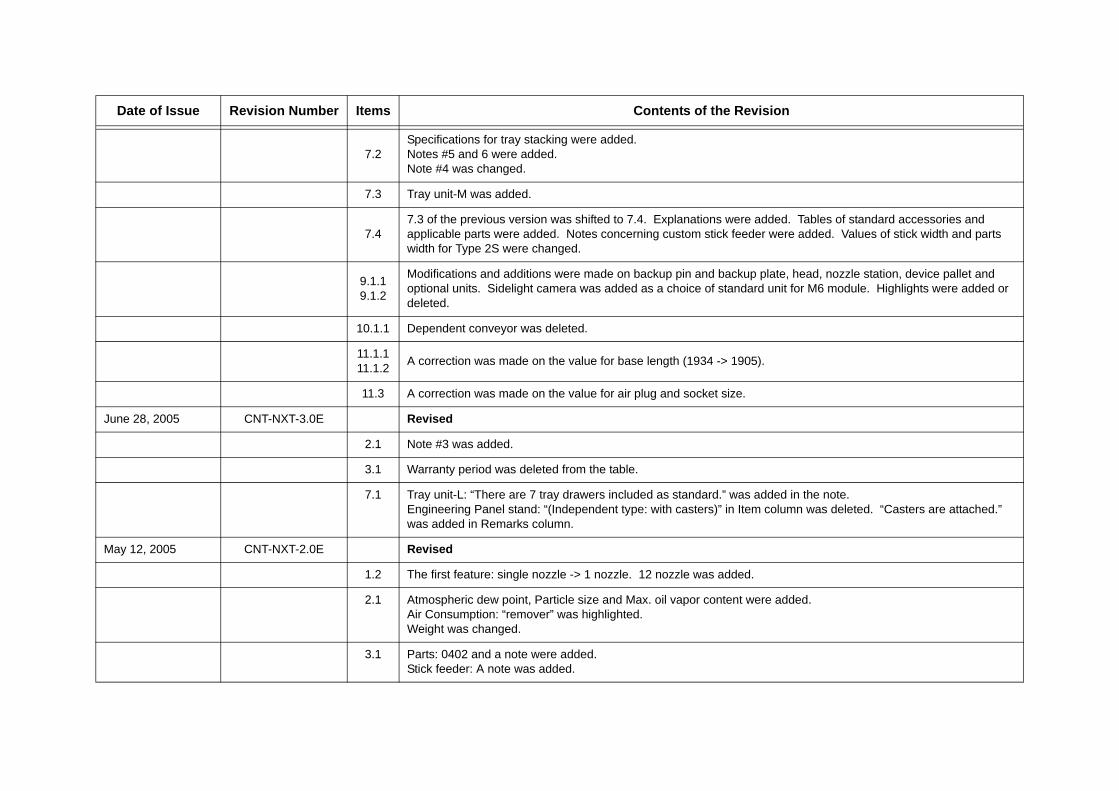
7.2Specifications for tray stacking were added.Notes #5 and 6 were added.Note #4 was changed.
7.3 Tray unit-M was added.
7.47.3 of the previous version was shifted to 7.4. Explanations were added. Tables of standard accessories and applicable parts were added. Notes concerning custom stick feeder were added. Values of stick width and parts width for Type 2S were changed.
9.1.19.1.2
Modifications and additions were made on backup pin and backup plate, head, nozzle station, device pallet and optional units. Sidelight camera was added as a choice of standard unit for M6 module. Highlights were added or deleted.
10.1.1 Dependent conveyor was deleted.
11.1.111.1.2 A correction was made on the value for base length (1934 -> 1905).
11.3 A correction was made on the value for air plug and socket size.
June 28, 2005 CNT-NXT-3.0E Revised
2.1 Note #3 was added.
3.1 Warranty period was deleted from the table.
7.1 Tray unit-L: “There are 7 tray drawers included as standard.” was added in the note.Engineering Panel stand: “(Independent type: with casters)” in Item column was deleted. “Casters are attached.” was added in Remarks column.
May 12, 2005 CNT-NXT-2.0E Revised
1.2 The first feature: single nozzle -> 1 nozzle. 12 nozzle was added.
2.1 Atmospheric dew point, Particle size and Max. oil vapor content were added.Air Consumption: “remover” was highlighted.Weight was changed.
3.1 Parts: 0402 and a note were added.Stick feeder: A note was added.
Date of Issue Revision Number Items Contents of the Revision
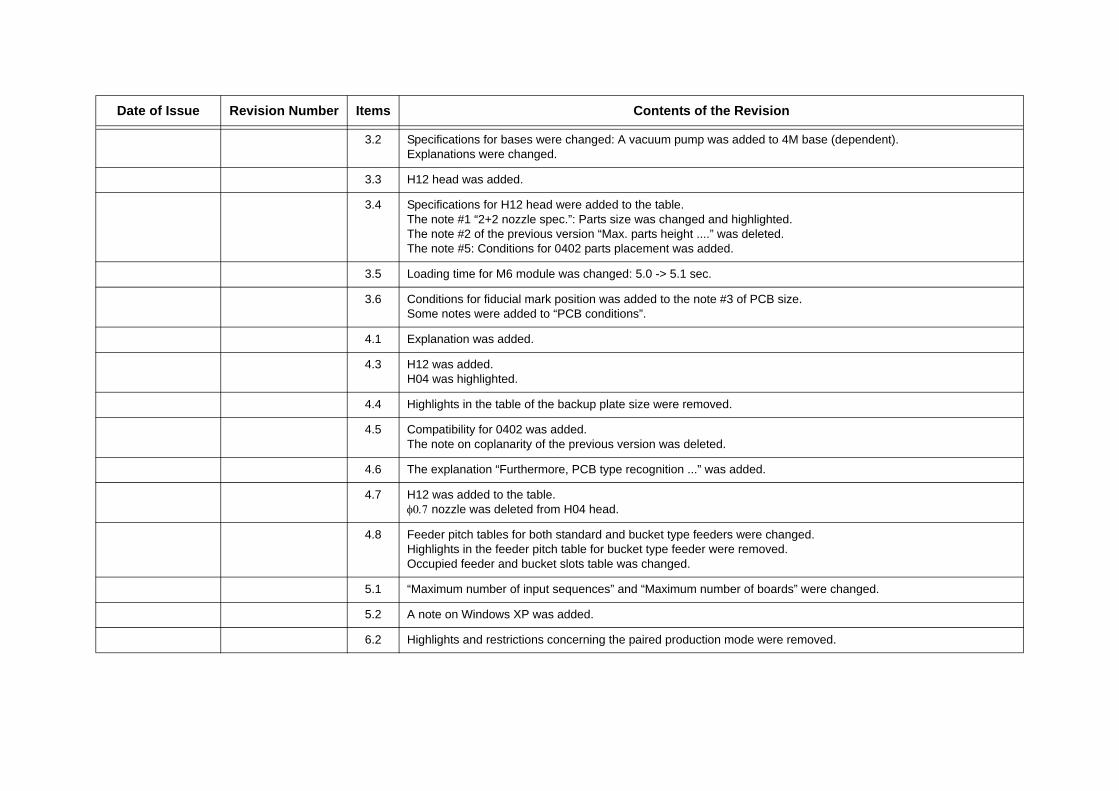
3.2 Specifications for bases were changed: A vacuum pump was added to 4M base (dependent).Explanations were changed.
3.3 H12 head was added.
3.4 Specifications for H12 head were added to the table.The note #1 “2+2 nozzle spec.”: Parts size was changed and highlighted. The note #2 of the previous version “Max. parts height ....” was deleted.The note #5: Conditions for 0402 parts placement was added.
3.5 Loading time for M6 module was changed: 5.0 -> 5.1 sec.
3.6 Conditions for fiducial mark position was added to the note #3 of PCB size.Some notes were added to “PCB conditions”.
4.1 Explanation was added.
4.3 H12 was added.H04 was highlighted.
4.4 Highlights in the table of the backup plate size were removed.
4.5 Compatibility for 0402 was added.The note on coplanarity of the previous version was deleted.
4.6 The explanation “Furthermore, PCB type recognition ...” was added.
4.7 H12 was added to the table.φ0.7 nozzle was deleted from H04 head.
4.8 Feeder pitch tables for both standard and bucket type feeders were changed.Highlights in the feeder pitch table for bucket type feeder were removed.Occupied feeder and bucket slots table was changed.
5.1 “Maximum number of input sequences” and “Maximum number of boards” were changed.
5.2 A note on Windows XP was added.
6.2 Highlights and restrictions concerning the paired production mode were removed.
Date of Issue Revision Number Items Contents of the Revision
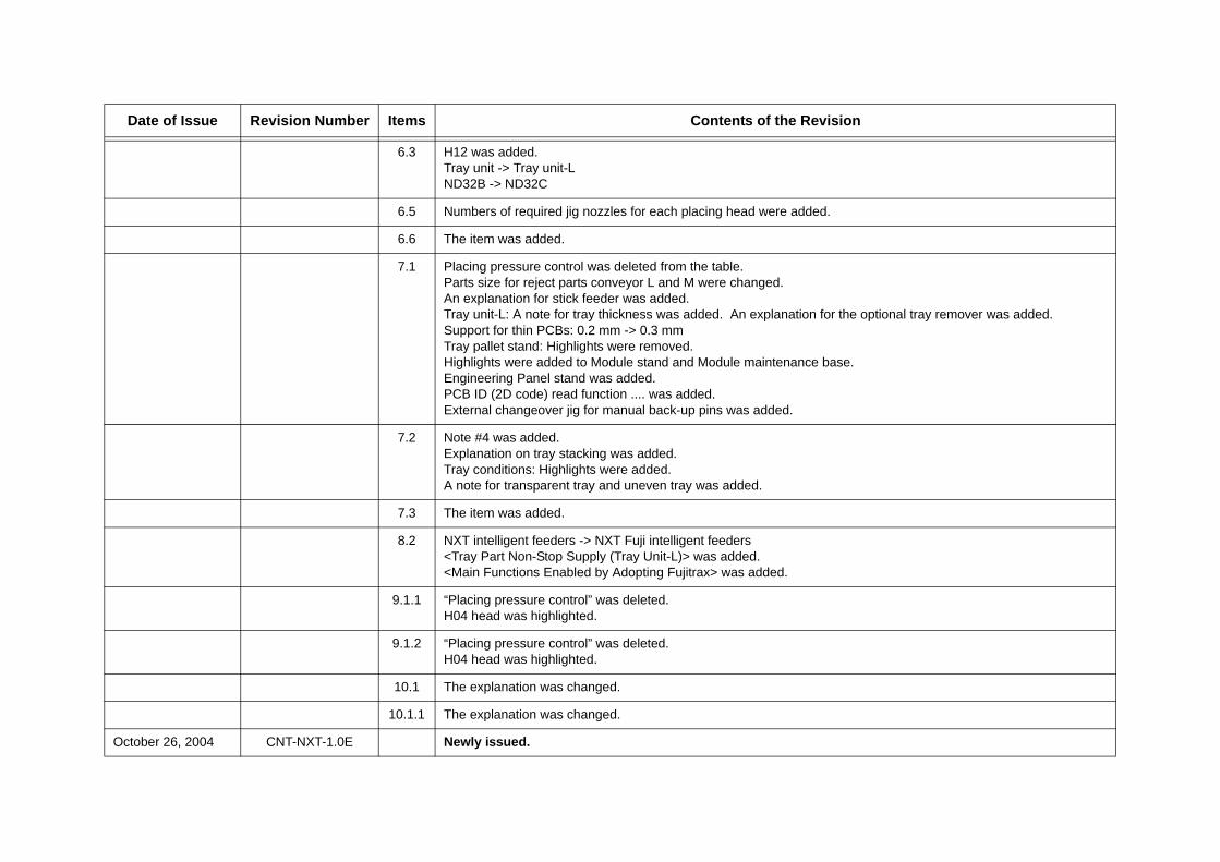
6.3 H12 was added.Tray unit -> Tray unit-LND32B -> ND32C
6.5 Numbers of required jig nozzles for each placing head were added.
6.6 The item was added.
7.1 Placing pressure control was deleted from the table.Parts size for reject parts conveyor L and M were changed.An explanation for stick feeder was added.Tray unit-L: A note for tray thickness was added. An explanation for the optional tray remover was added.Support for thin PCBs: 0.2 mm -> 0.3 mmTray pallet stand: Highlights were removed.Highlights were added to Module stand and Module maintenance base.Engineering Panel stand was added.PCB ID (2D code) read function .... was added.External changeover jig for manual back-up pins was added.
7.2 Note #4 was added.Explanation on tray stacking was added.Tray conditions: Highlights were added.A note for transparent tray and uneven tray was added.
7.3 The item was added.
8.2 NXT intelligent feeders -> NXT Fuji intelligent feeders<Tray Part Non-Stop Supply (Tray Unit-L)> was added.<Main Functions Enabled by Adopting Fujitrax> was added.
9.1.1 “Placing pressure control” was deleted.H04 head was highlighted.
9.1.2 “Placing pressure control” was deleted.H04 head was highlighted.
10.1 The explanation was changed.
10.1.1 The explanation was changed.
October 26, 2004 CNT-NXT-1.0E Newly issued.
Date of Issue Revision Number Items Contents of the Revision


![CERN-EP-2017-255 ALICE Collaboration arXiv:1709.08522v2 ... · pp [14] collisions, photo-production gp [15] and e+e annihilation at ¡(nS) [16] and Z0 [17] energies. Measurements](https://img.pdfslide.net/doc/110x75/5f6f5cb07ea07230333030e1/cern-ep-2017-255-alice-collaboration-arxiv170908522v2-pp-14-collisions.jpg)