Embed Size (px)
Citation preview
Fundamentals of Power Electronics Chapter 1: Introduction1
Fundamentals of Power ElectronicsSecond edition
Robert W. EricksonDragan Maksimovic
University of Colorado, Boulder
Fundamentals of Power Electronics Chapter 1: Introduction2
Chapter 1: Introduction
1.1. Introduction to power processing1.2. Some applications of power electronics1.3. Elements of power electronics
Summary of the course
Fundamentals of Power Electronics Chapter 1: Introduction3
1.1 Introduction to Power Processing
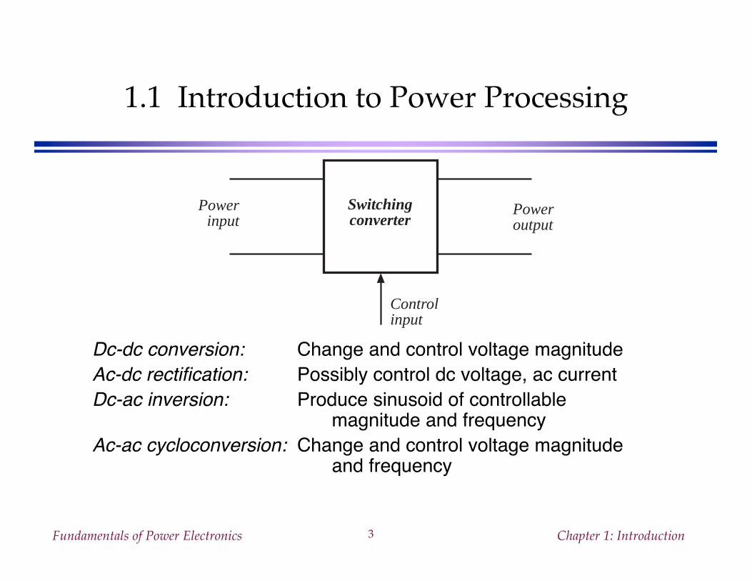
Dc-dc conversion: Change and control voltage magnitudeAc-dc rectification: Possibly control dc voltage, ac currentDc-ac inversion: Produce sinusoid of controllable
magnitude and frequencyAc-ac cycloconversion: Change and control voltage magnitude
and frequency
Switchingconverter
Powerinput
Poweroutput
Controlinput
Fundamentals of Power Electronics Chapter 1: Introduction4
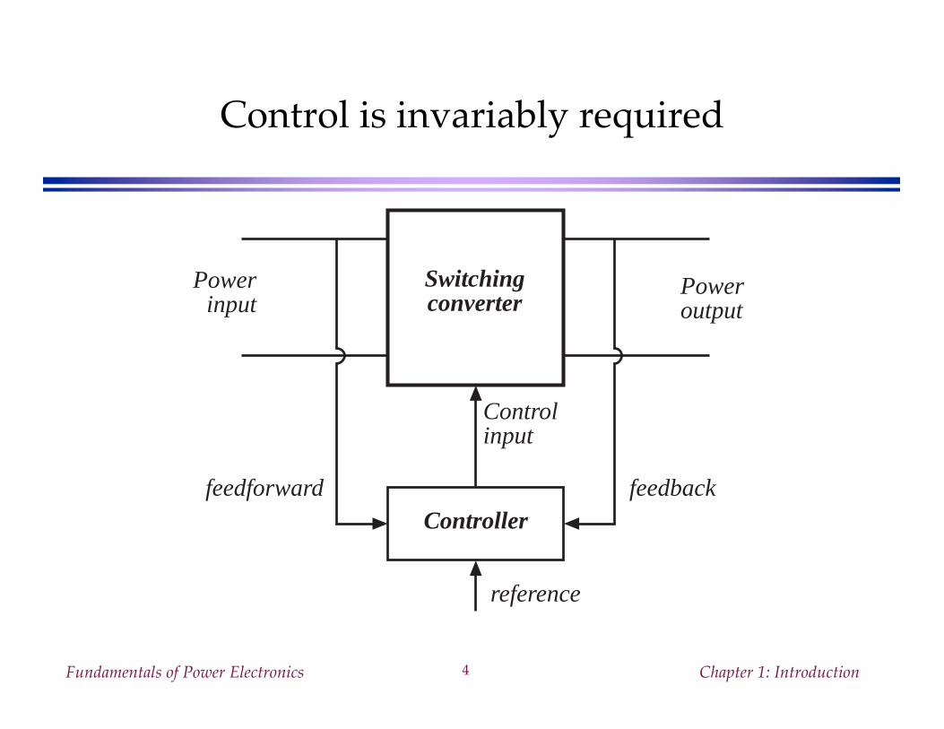
Control is invariably required
Switchingconverter
Powerinput
Poweroutput
Controlinput
Controller
reference
feedbackfeedforward
Fundamentals of Power Electronics Chapter 1: Introduction5
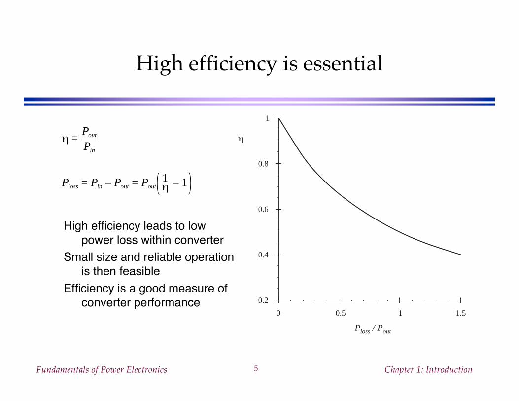
High efficiency is essential
High efficiency leads to lowpower loss within converter
Small size and reliable operationis then feasible
Efficiency is a good measure ofconverter performance
0 0.5 1 1.5
0.2
0.4
0.6
0.8
1
Ploss / Pout
ηη =Pout
Pin
Ploss = Pin – Pout = Pout1η – 1
Fundamentals of Power Electronics Chapter 1: Introduction6
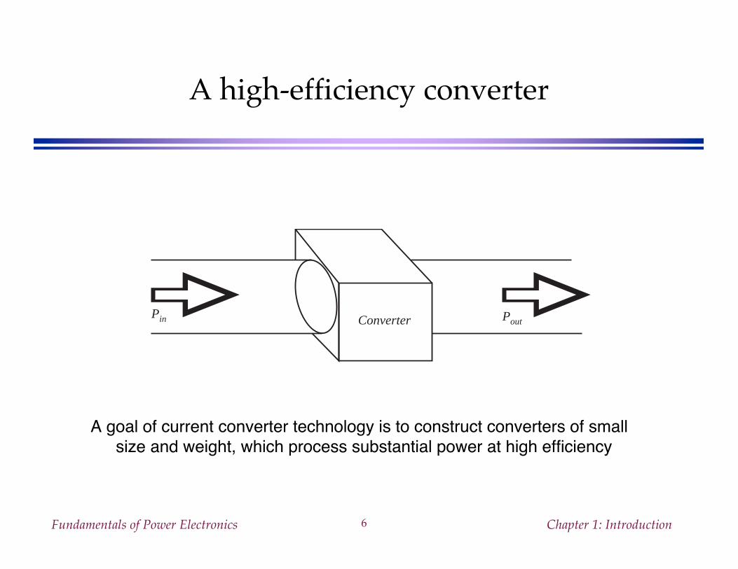
A high-efficiency converter
A goal of current converter technology is to construct converters of smallsize and weight, which process substantial power at high efficiency
ConverterPin Pout
Fundamentals of Power Electronics Chapter 1: Introduction7
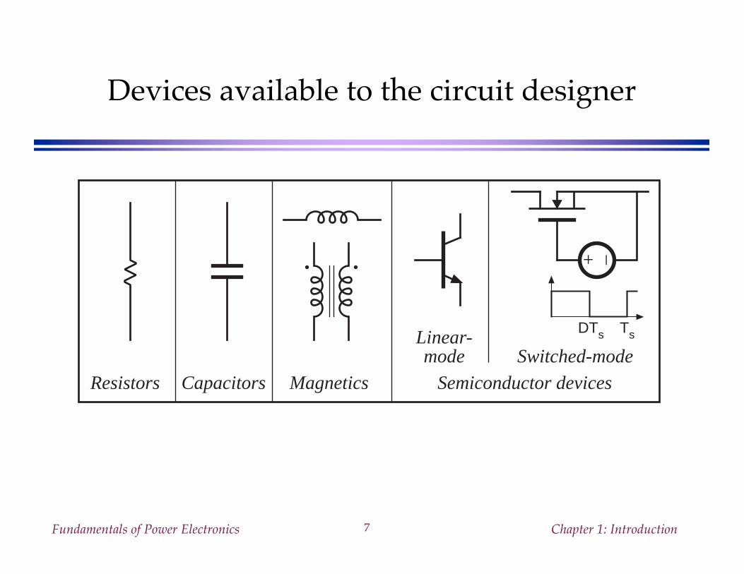
Devices available to the circuit designer
DTs Ts
Resistors Capacitors Magnetics Semiconductor devices
Linear-mode
+ –
Switched-mode
Fundamentals of Power Electronics Chapter 1: Introduction8
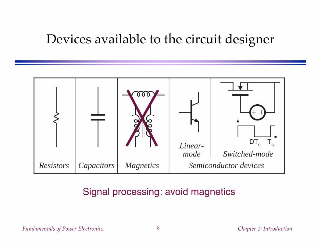
Devices available to the circuit designer
Signal processing: avoid magnetics
DTs Ts
Resistors Capacitors Magnetics Semiconductor devices
Linear-mode
+ –
Switched-mode
Fundamentals of Power Electronics Chapter 1: Introduction9
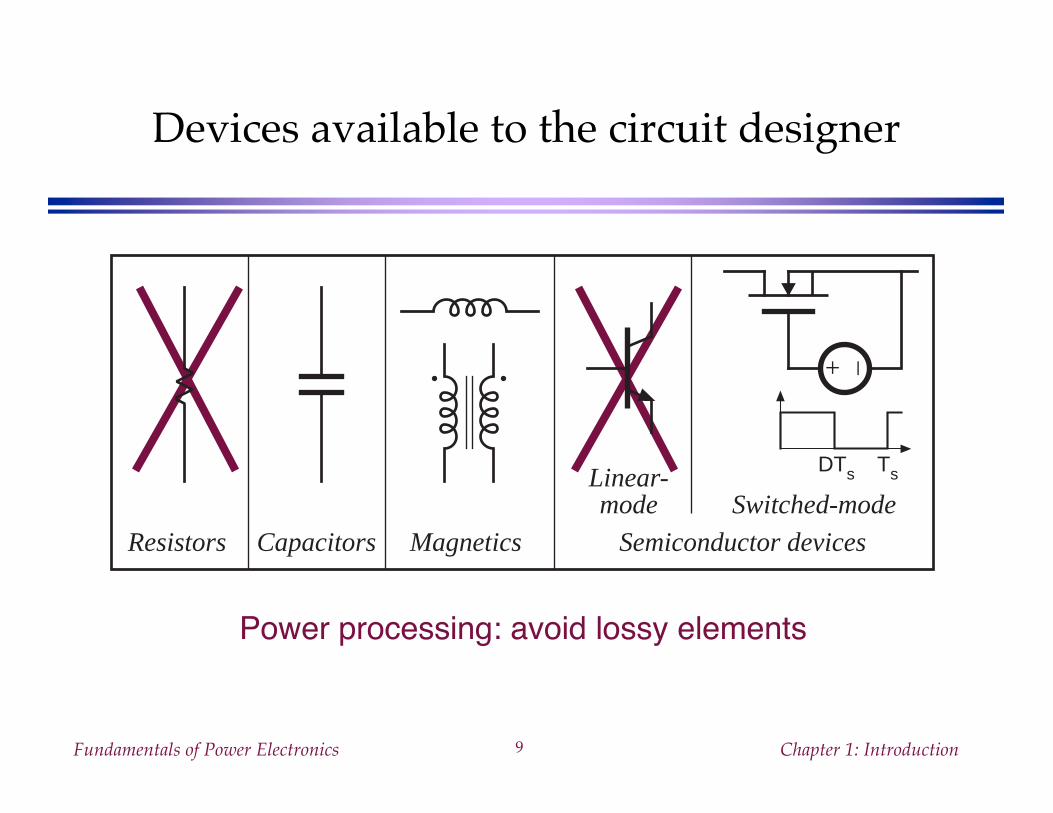
Devices available to the circuit designer
Power processing: avoid lossy elements
DTs Ts
Resistors Capacitors Magnetics Semiconductor devices
Linear-mode
+ –
Switched-mode
Fundamentals of Power Electronics Chapter 1: Introduction10
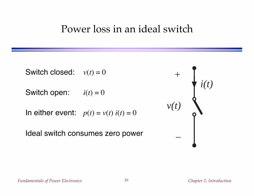
Power loss in an ideal switch
Switch closed: v(t) = 0
Switch open: i(t) = 0
In either event: p(t) = v(t) i(t) = 0
Ideal switch consumes zero power
+
v(t)
–
i(t)
Fundamentals of Power Electronics Chapter 1: Introduction11
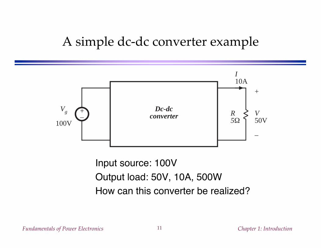
A simple dc-dc converter example
Input source: 100VOutput load: 50V, 10A, 500WHow can this converter be realized?
+– R
5Ω
+
V50V
–
Vg
100V
I10A
Dc-dcconverter
Fundamentals of Power Electronics Chapter 1: Introduction12
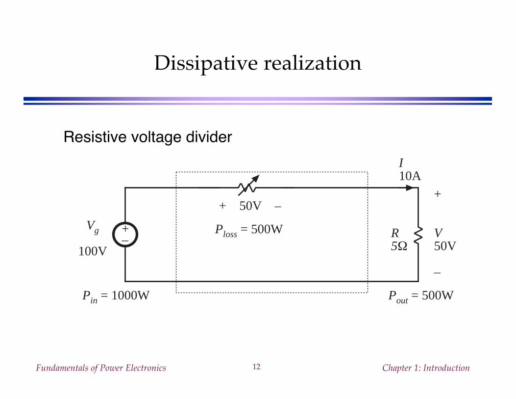
Dissipative realization
Resistive voltage divider
+– R
5Ω
+
V50V
–
Vg
100V
I10A
+ 50V –
Ploss = 500W
Pout = 500WPin = 1000W
Fundamentals of Power Electronics Chapter 1: Introduction13
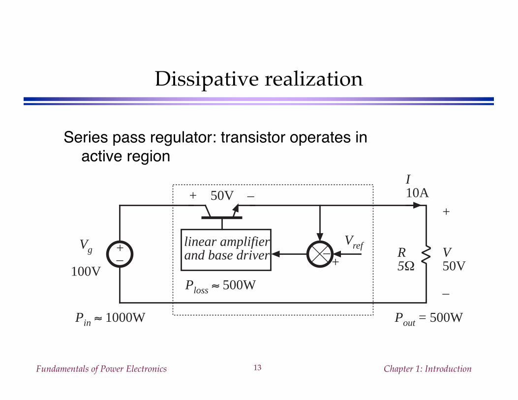
Dissipative realization
Series pass regulator: transistor operates inactive region
+– R
5Ω
+
V50V
–
Vg
100V
I10A+ 50V –
Ploss ≈ 500W
Pout = 500WPin ≈ 1000W
+–linear amplifierand base driver
Vref
Fundamentals of Power Electronics Chapter 1: Introduction14
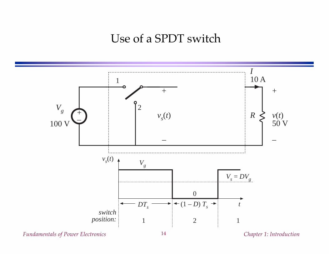
Use of a SPDT switch
+– R
+
v(t)50 V
–
1
2
+
vs(t)
–
Vg
100 V
I10 A
vs(t) Vg
DTs (1 – D) Ts
0
tswitch
position: 1 2 1
Vs = DVg
Fundamentals of Power Electronics Chapter 1: Introduction15
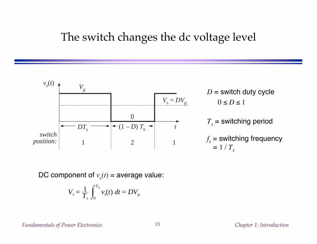
The switch changes the dc voltage level
D = switch duty cycle0 ≤ D ≤ 1
Ts = switching period
fs = switching frequency = 1 / Ts
Vs = 1Ts
vs(t) dt0
Ts
= DVg
DC component of vs(t) = average value:
vs(t) Vg
DTs (1 – D) Ts
0
tswitch
position: 1 2 1
Vs = DVg
Fundamentals of Power Electronics Chapter 1: Introduction16
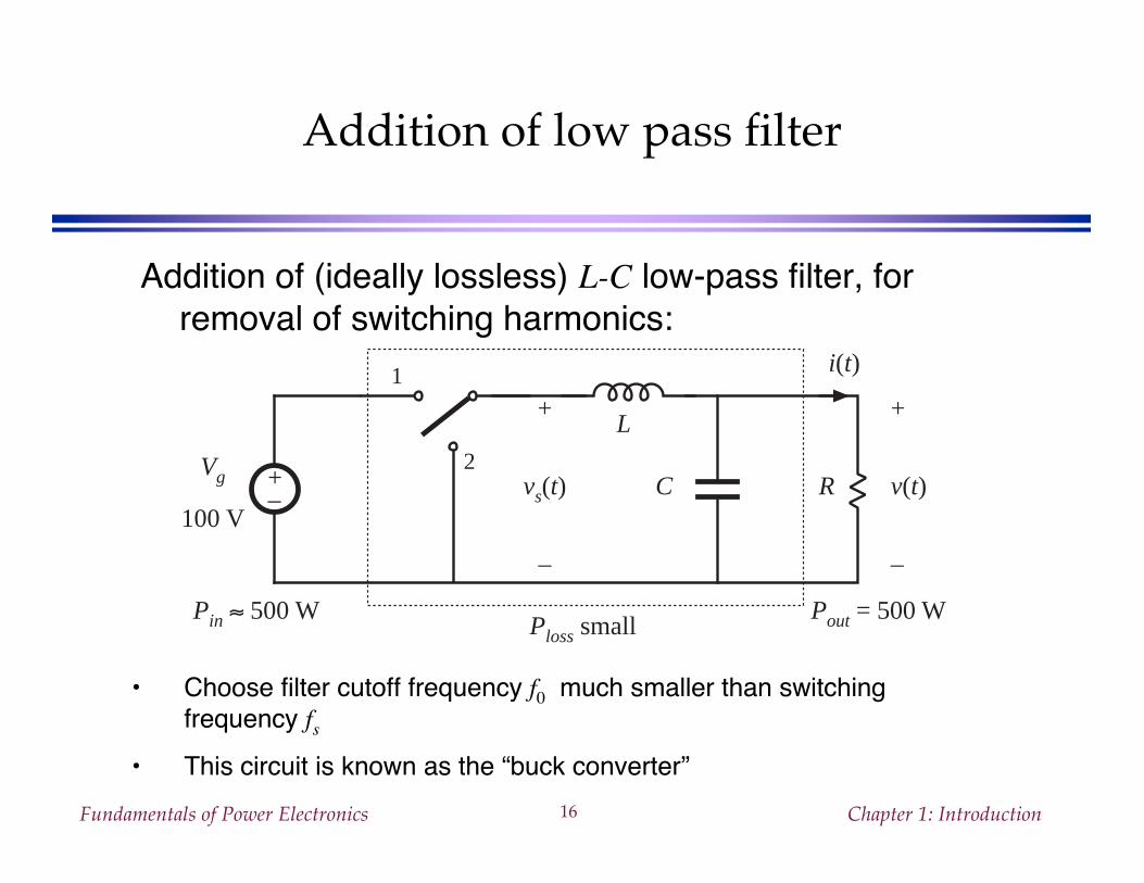
Addition of low pass filter
Addition of (ideally lossless) L-C low-pass filter, forremoval of switching harmonics:
• Choose filter cutoff frequency f0 much smaller than switchingfrequency fs
• This circuit is known as the “buck converter”
+– R
+
v(t)
–
1
2
+
vs(t)
–
Vg
100 V
i(t)
L
C
Ploss smallPout = 500 WPin ≈ 500 W
Fundamentals of Power Electronics Chapter 1: Introduction17
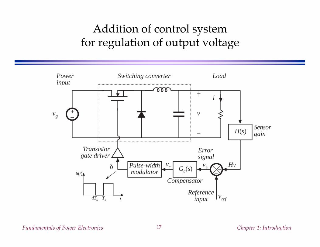
Addition of control systemfor regulation of output voltage
δ(t)
TsdTs t
+–
+
v
–
vg
Switching converterPowerinput
Load–+
Compensator
vrefReference
input
HvPulse-widthmodulator
vc
Transistorgate driver
δ Gc(s)
H(s)
ve
Errorsignal
Sensorgain
i
Fundamentals of Power Electronics Chapter 1: Introduction18
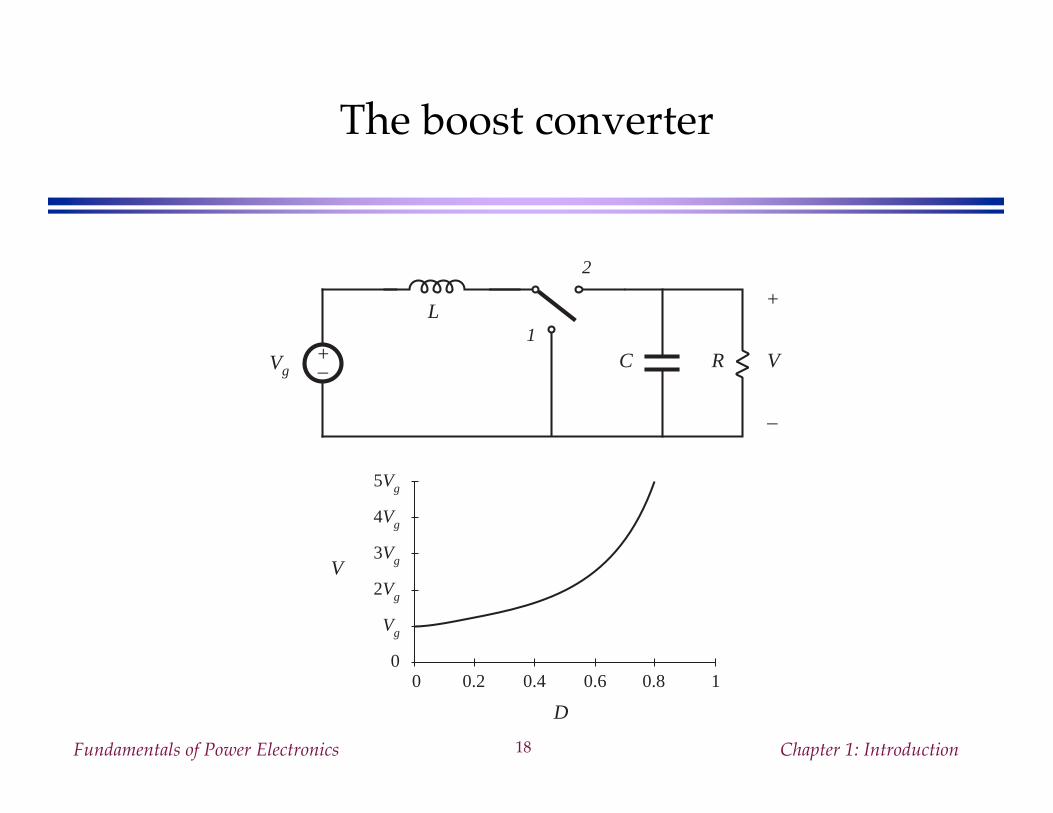
The boost converter
+–
L
C R
+
V
–
1
2
Vg
D
0 0.2 0.4 0.6 0.8 1
V
5Vg
4Vg
3Vg
2Vg
Vg
0
Fundamentals of Power Electronics Chapter 1: Introduction19
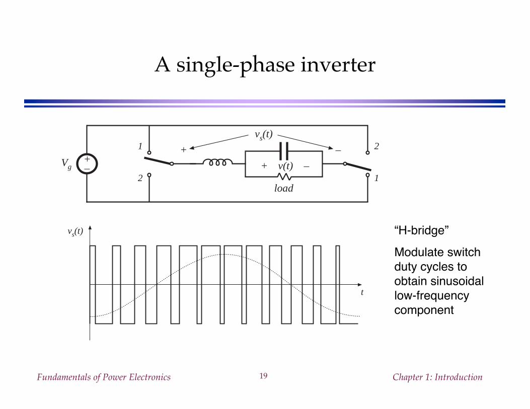
A single-phase inverter
1
2
+–
load
+ v(t) –
2
1
Vg
vs(t)
+ –
t
vs(t) “H-bridge”Modulate switchduty cycles toobtain sinusoidallow-frequencycomponent
Fundamentals of Power Electronics Chapter 1: Introduction20
1.2 Several applications of power electronics
Power levels encountered in high-efficiency converters• less than 1 W in battery-operated portable equipment• tens, hundreds, or thousands of watts in power supplies for
computers or office equipment• kW to MW in variable-speed motor drives• 1000 MW in rectifiers and inverters for utility dc transmission
lines
Fundamentals of Power Electronics Chapter 1: Introduction21
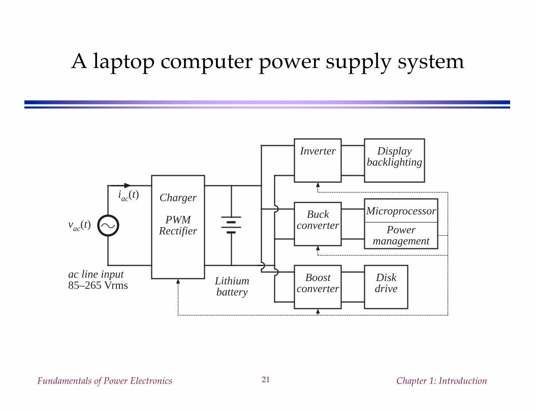
A laptop computer power supply system
vac(t)
iac(t) Charger
PWMRectifier
Lithiumbattery
ac line input85–265 Vrms
Inverter
Buckconverter
Boostconverter
Displaybacklighting
Microprocessor
Powermanagement
Diskdrive
Fundamentals of Power Electronics Chapter 1: Introduction22
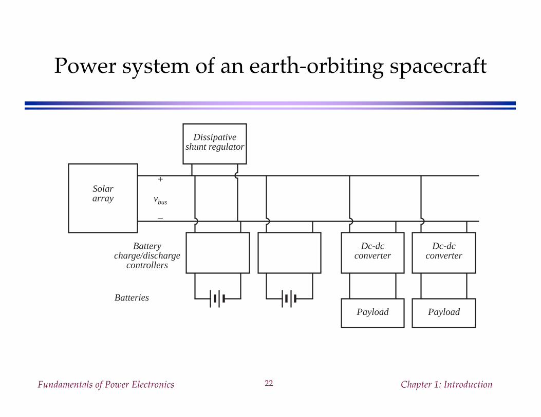
Power system of an earth-orbiting spacecraft
Solararray
+
vbus
–
Batteries
Batterycharge/discharge
controllers
Dc-dcconverter
Payload
Dc-dcconverter
Payload
Dissipativeshunt regulator
Fundamentals of Power Electronics Chapter 1: Introduction23
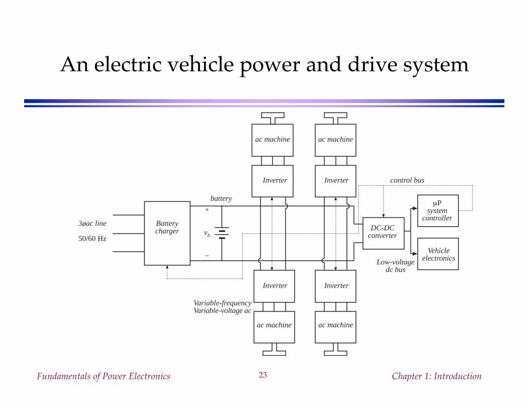
An electric vehicle power and drive system
3øac line
50/60 Hz
Batterycharger
battery
+
vb
–
Variable-frequencyVariable-voltage ac
Inverter
ac machine
Inverter
Inverter
ac machine
DC-DCconverter
µPsystem
controller
VehicleelectronicsLow-voltage
dc bus
control bus
ac machine ac machine
Inverter