Embed Size (px)
Citation preview
1
1
Fundamentals of Structural DesignPart of Steel Structures
Civil Engineering for Bachelors133FSTD
Teacher: Zdeněk SokolOffice number: B619
2
Syllabus of lectures
1. Introduction, history of steel structures, the applications and some representative structures, production of steel
2. Steel products, material properties and testing, steel grades3. Manufacturing of steel structures, welding, mechanical fasteners4. Safety of structures, limit state design, codes and specifications for the
design5. Tension, compression, buckling6. Classification of cross sections, bending, shear, serviceability limit states7. Buckling of webs, lateral-torsional stability, torsion, combination of
internal forces 8. Fatigue9. Design of bolted and welded connections10. Steel-concrete composite structures11. Fire and corrosion resistance, protection of steel structures, life cycle
assessment
2
3
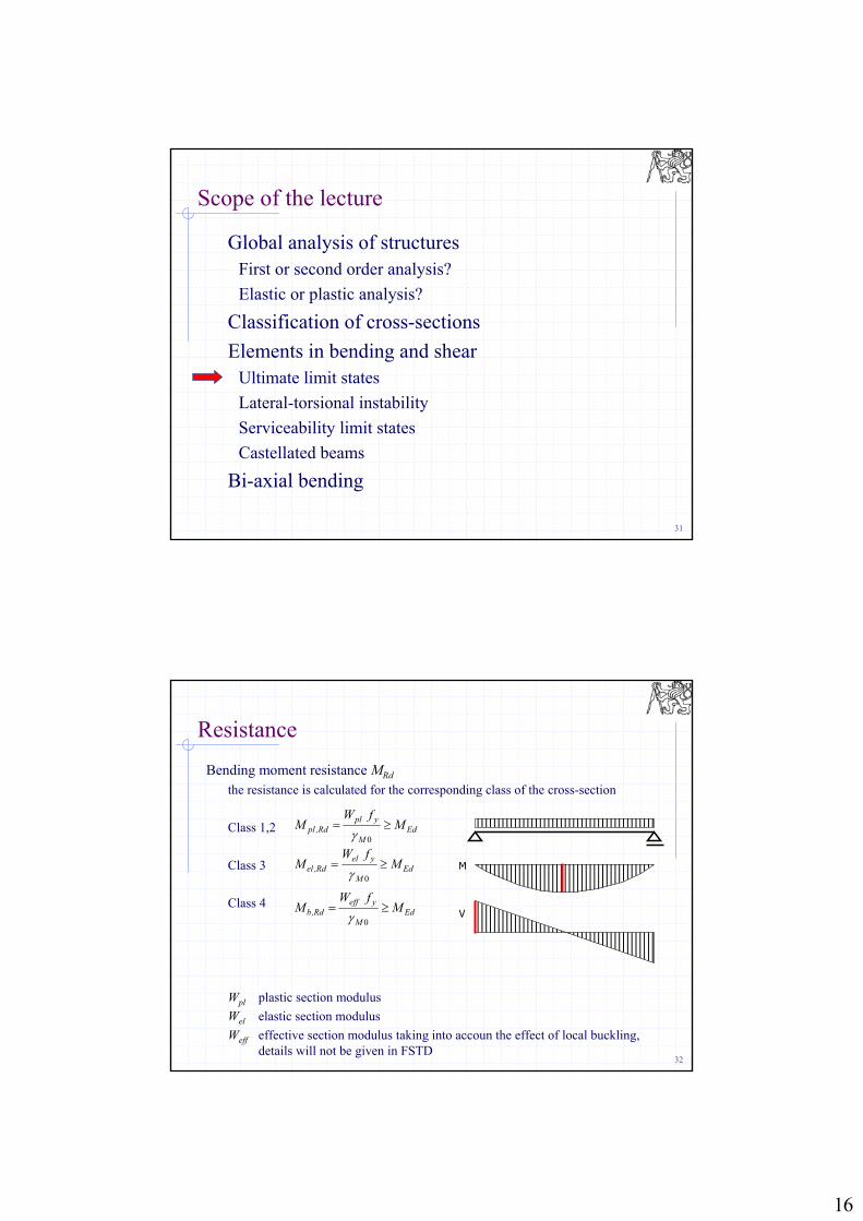
Scope of the lecture
Global analysis of structuresFirst or second order analysis?
Elastic or plastic analysis?
Classification of cross-sections
Elements in bending and shearUltimate limit states
Lateral-torsional instability
Serviceability limit states
Castellated beams
Bi-axial bending
4
Global analysis of structures
Global analysis of structures is the procedure which calculates the internal forces and deformations of the structure
First order or second order analysis?
Elastic or plastic analysis?
3
5
Imperfections
There are three types of imperfections in the structure
Geometric imperfectionsbow shaped elements
Material imperfectionsresidual stress
Structural imperfectionsrandom eccentricity at joints
These are introduced into calculation as equivalent geometric imperfections
6
Imperfections
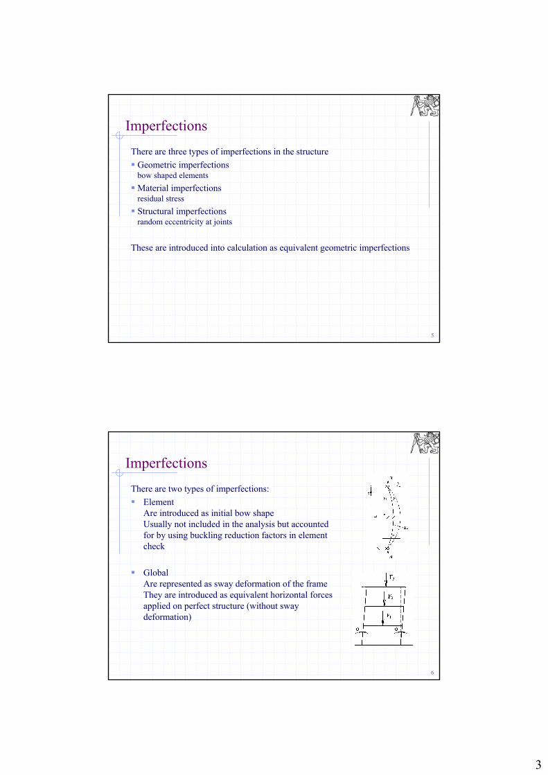
There are two types of imperfections:
Element Are introduced as initial bow shapeUsually not included in the analysis but accounted for by using buckling reduction factors in element check
GlobalAre represented as sway deformation of the frameThey are introduced as equivalent horizontal forces applied on perfect structure (without sway deformation)
4
7
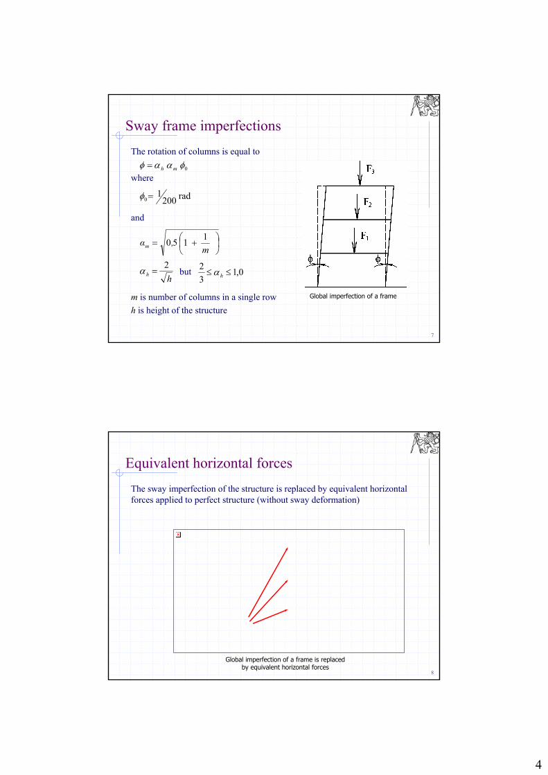
The rotation of columns is equal to
where
and
m is number of columns in a single row
h is height of the structure
Sway frame imperfections
0 mh
rad2001 0
m ,αm
1150
0,13
2 hh
h
2 but
Global imperfection of a frame
8
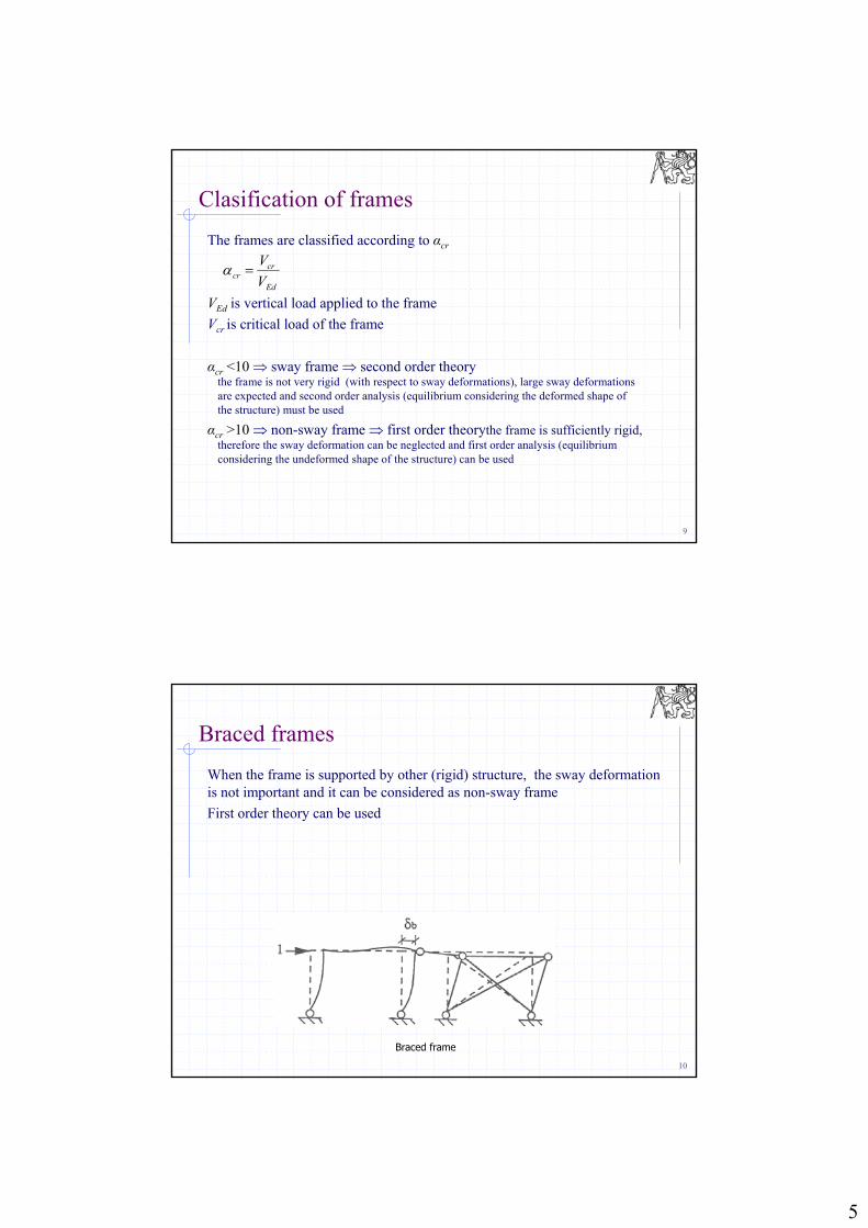
Equivalent horizontal forces
The sway imperfection of the structure is replaced by equivalent horizontal forces applied to perfect structure (without sway deformation)
Global imperfection of a frame is replaced by equivalent horizontal forces
5
9
Clasification of frames
The frames are classified according to αcr
VEd is vertical load applied to the frame
Vcr is critical load of the frame
αcr <10 sway frame second order theorythe frame is not very rigid (with respect to sway deformations), large sway deformations are expected and second order analysis (equilibrium considering the deformed shape of the structure) must be used
αcr >10 non-sway frame first order theorythe frame is sufficiently rigid, therefore the sway deformation can be neglected and first order analysis (equilibrium considering the undeformed shape of the structure) can be used
Ed
crcr V
V
10
Braced frames
When the frame is supported by other (rigid) structure, the sway deformation is not important and it can be considered as non-sway frame
First order theory can be used
Braced frame
6
11
Global analysis of frames
Methods of analysis First-order theory = geometrically linear internal forces are calculated on theoretical geometry of structure principle of superposition is valid stability: separate buckling check of each element is performed
Second-order theory = geometrically non-linear internal forces calculated on deformed structure principle of superposition is not valid (several load combinations must be solved
separately)
12
Scope of the lecture
Global analysis of structuresFirst or second order analysis?Elastic or plastic analysis?
Classification of cross-sectionsElements in bending and shear
Ultimate limit statesLateral-torsional instabilityServiceability limit statesCastellated beams
Bi-axial bending
7
13
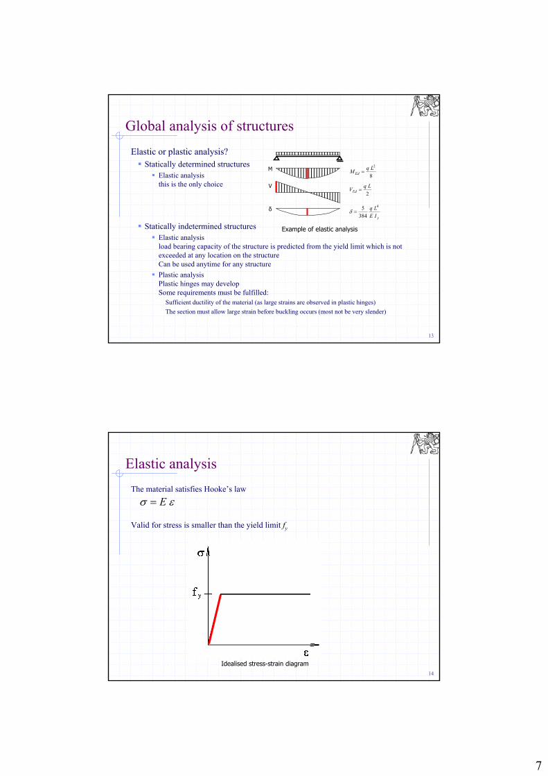
Global analysis of structures
Elastic or plastic analysis? Statically determined structures
Elastic analysisthis is the only choice
Statically indetermined structures Elastic analysis
load bearing capacity of the structure is predicted from the yield limit which is not exceeded at any location on the structureCan be used anytime for any structure
Plastic analysisPlastic hinges may developSome requirements must be fulfilled:
Sufficient ductility of the material (as large strains are observed in plastic hinges)
The section must allow large strain before buckling occurs (most not be very slender)
Example of elastic analysis
M
V
8
2LqM Ed
2
LqVEd
yIE
Lq 4
384
5δ
14
Elastic analysis
The material satisfies Hooke’s law
Valid for stress is smaller than the yield limit fy
Idealised stress-strain diagram
E
8
15
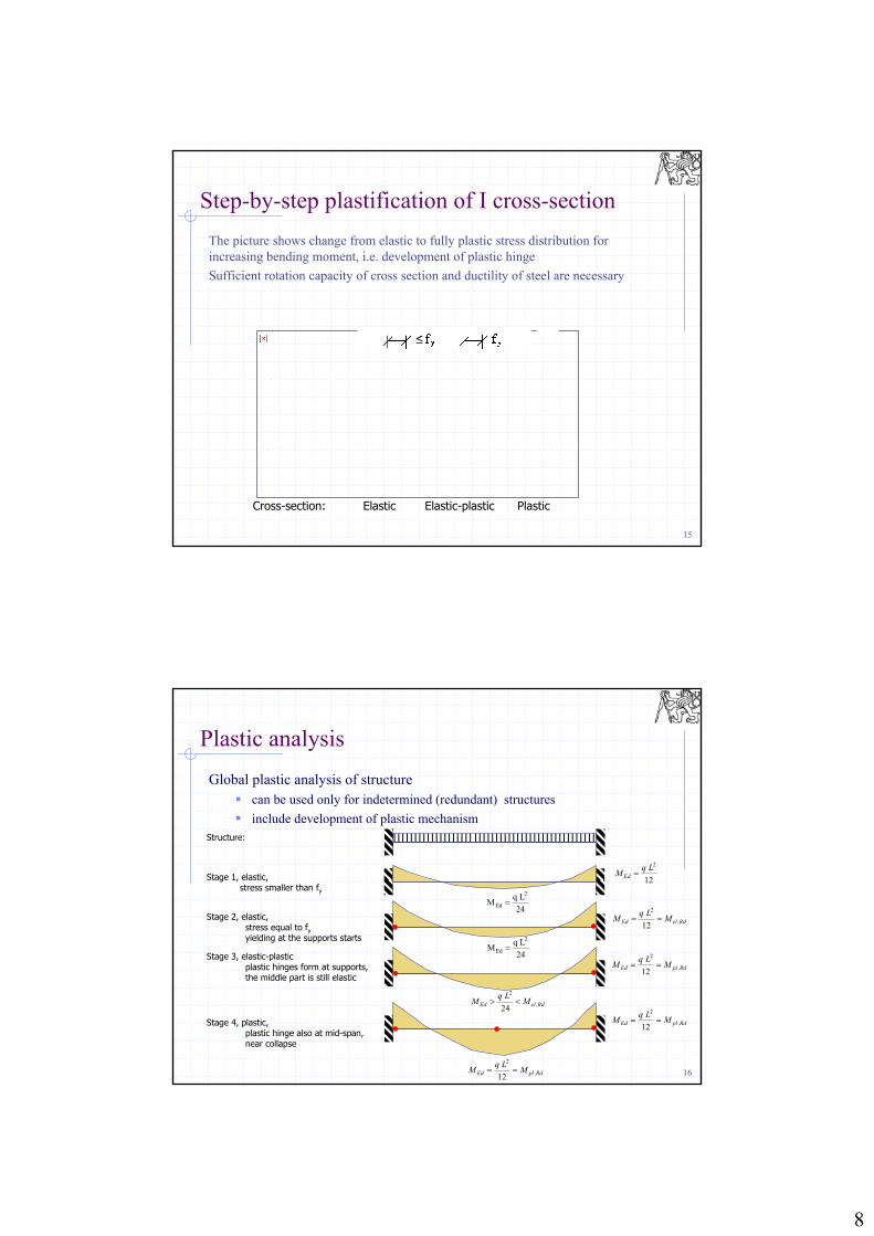
Step-by-step plastification of I cross-section
The picture shows change from elastic to fully plastic stress distribution for increasing bending moment, i.e. development of plastic hinge
Sufficient rotation capacity of cross section and ductility of steel are necessary
Cross-section: Elastic Elastic-plastic Plastic
≤
16
Plastic analysis
Global plastic analysis of structure can be used only for indetermined (redundant) structures
include development of plastic mechanismStructure:
Rd,elEd MLq
M 24
2
Rd,plEd MLq
M 12
2Stage 3, elastic-plasticplastic hinges form at supports, the middle part is still elastic
24
LqM
2
Ed
Rd,elEd MLq
M 12
2Stage 2, elastic,
stress equal to fyyielding at the supports starts
24
LqM
2
Ed
12
2LqM Ed Stage 1, elastic,
stress smaller than fy
Rd,plEd MLq
M 12
2
Rd,plEd MLq
M 12
2
Stage 4, plastic, plastic hinge also at mid-span,near collapse
9
17
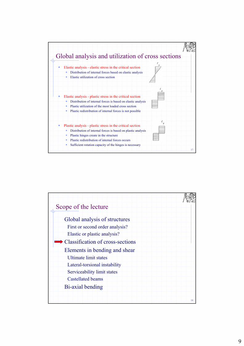
Global analysis and utilization of cross sections
Elastic analysis - elastic stress in the critical section Distribution of internal forces based on elastic analysis
Elastic utilization of cross section
Elastic analysis - plastic stress in the critical section Distribution of internal forces is based on elastic analysis
Plastic utilization of the most loaded cross section
Plastic redistribution of internal forces is not possible
Plastic analysis - plastic stress in the critical section Distribution of internal forces is based on plastic analysis
Plastic hinges create in the structure
Plastic redistribution of internal forces occurs
Sufficient rotation capacity of the hinges is necessary
18
Scope of the lecture
Global analysis of structuresFirst or second order analysis?
Elastic or plastic analysis?
Classification of cross-sections
Elements in bending and shearUltimate limit states
Lateral-torsional instability
Serviceability limit states
Castellated beams
Bi-axial bending
10
19
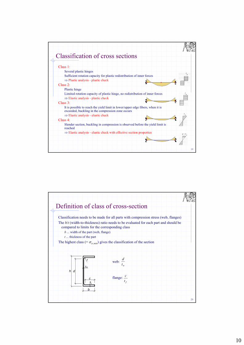
Classification of cross sections
Class 1:Several plastic hinges Sufficient rotation capacity for plastic redistribution of inner forces Plastic analysis - plastic check
Class 2:Plastic hingeLimited rotation capacity of plastic hinge, no redistribution of inner forces Elastic analysis - plastic check
Class 3:It is possible to reach the yield limit in lower/upper edge fibers, when it is exceeded, buckling in the compression zone occurs Elastic analysis - elastic check
Class 4:Slender section, buckling in compression is observed before the yield limit is reached Elastic analysis - elastic check with effective section properties
20
Definition of class of cross-section
Classification needs to be made for all parts with compression stress (web, flanges)
The b/t (width-to-thickness) ratio needs to be evaluated for each part and should be compared to limits for the corresponding class
b ... width of the part (web, flange)
t ... thickness of the part
The highest class (= cr,min) gives the classification of the section
d
b
r
h
tf
tw
c
web:
flange:
wt
d
ft
c
11
21
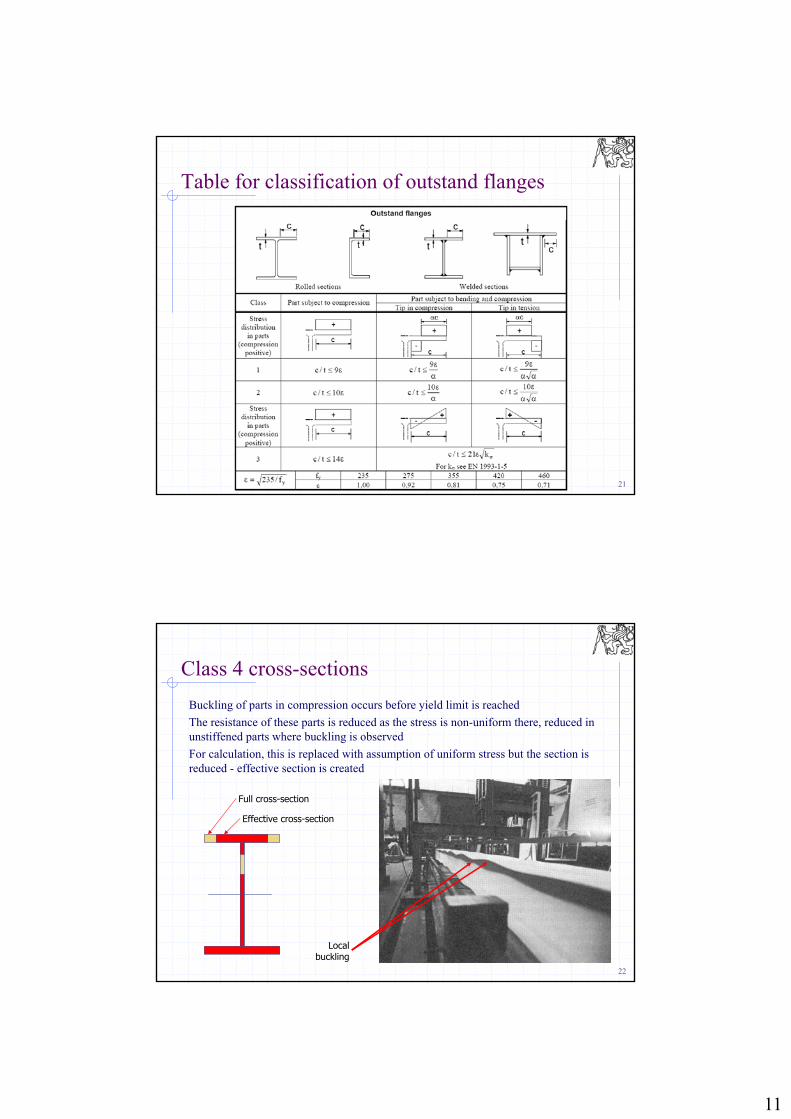
Table for classification of outstand flanges
22
Class 4 cross-sections
Buckling of parts in compression occurs before yield limit is reached
The resistance of these parts is reduced as the stress is non-uniform there, reduced in unstiffened parts where buckling is observed
For calculation, this is replaced with assumption of uniform stress but the section is reduced - effective section is created
Full cross-section
Effective cross-section
Local buckling
12
23
Scope of the lecture
Global analysis of structuresFirst or second order analysis?Elastic or plastic analysis?
Classification of cross-sectionsElements in bending and shear
Ultimate limit statesLateral-torsional instabilityServiceability limit statesCastellated beams
Bi-axial bending
24
Elements loaded by bending moment
Floor and roof beamsusually form perpendicular grid, i.e. system of secondary beams (these directly support the concrete slab or roof cladding) and primary beams (these support the secondary beams)
Framesthe elements are loaded by combination of axial force and bending moment, therefore are not typical beams, but there is a lot of similarities
Castellated beamsare made from hot-rolled sections cut along the zig-zag line and welded togetherthe design procedure is quite different from “standard” beams, but these are also loaded by bending moment
Latticed beams (trusses)these are made from elements resisting tension and compression, will not be considered here
Composite beamsthe compression is transferred by concrete slab on top of steel beams, there is special lecture about composite structures in FSTD
13
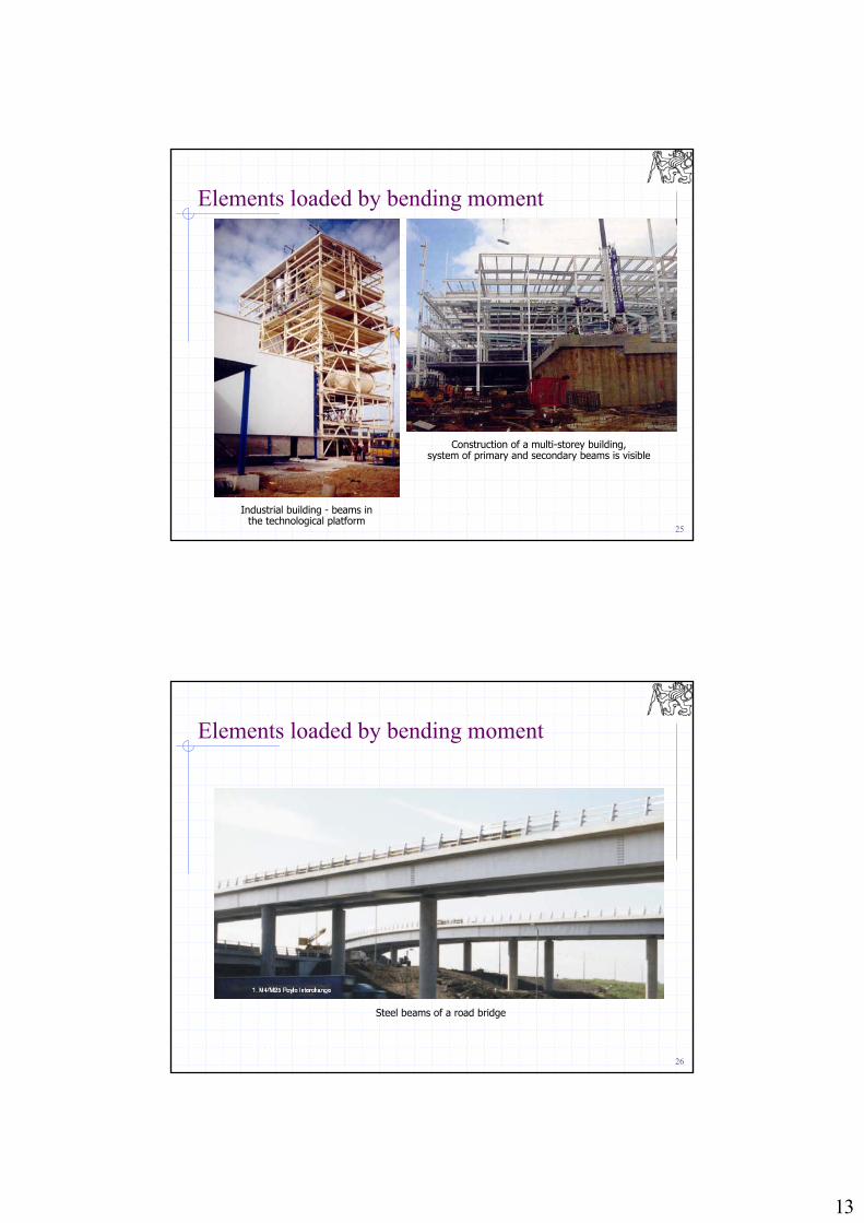
25
Industrial building - beams in the technological platform
Construction of a multi-storey building,system of primary and secondary beams is visible
Elements loaded by bending moment
26
Steel beams of a road bridge
Elements loaded by bending moment
14
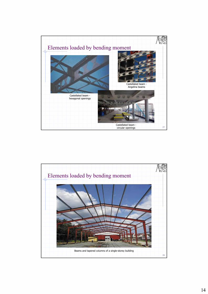
27
Castellated beam -hexagonal openings
Elements loaded by bending moment
Castellated beam -circular openings
Castellated beam -Angelina beams
28
Beams and tapered columns of a single-storey building
Elements loaded by bending moment
15
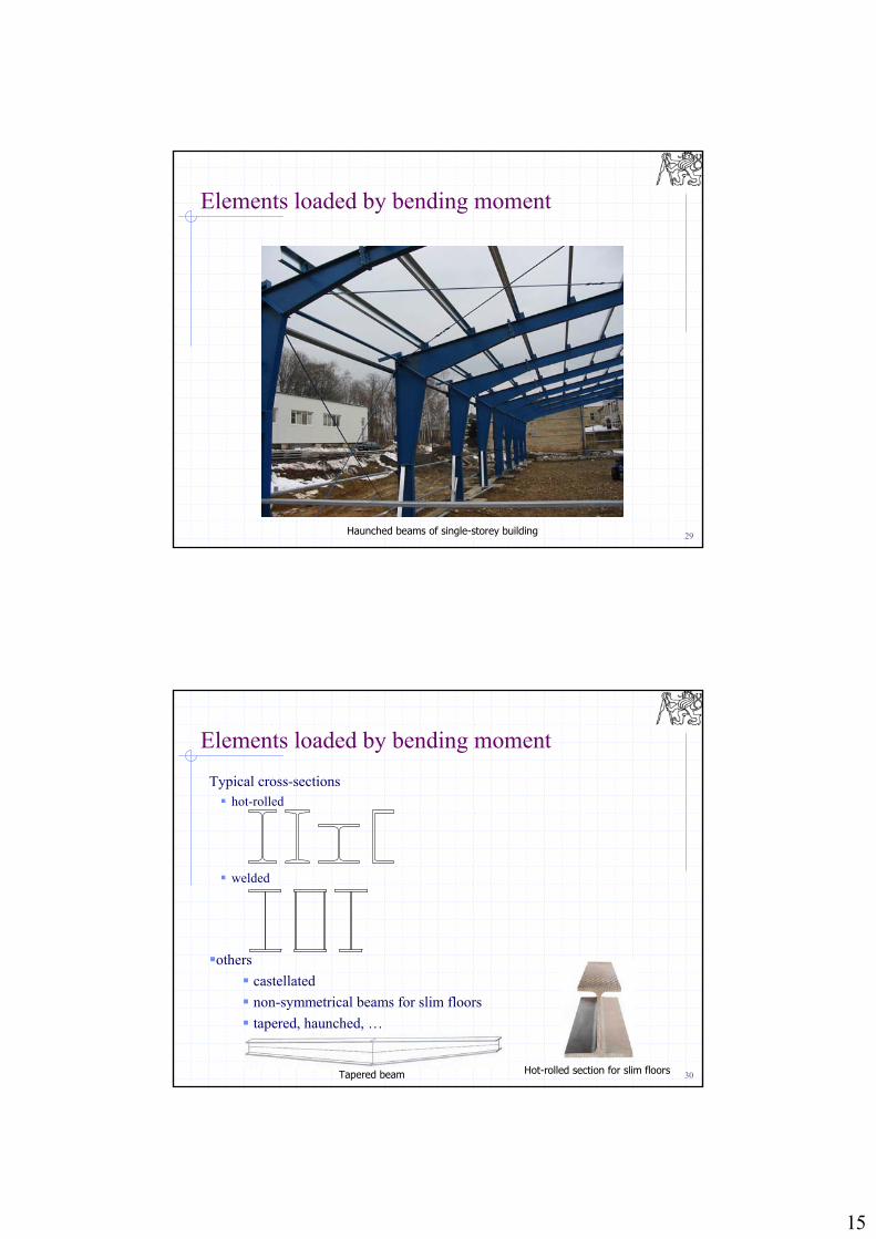
29Haunched beams of single-storey building
Elements loaded by bending moment
30
Typical cross-sections hot-rolled
welded
others
castellated
non-symmetrical beams for slim floors
tapered, haunched, …
Elements loaded by bending moment
Hot-rolled section for slim floorsTapered beam
16
31
Scope of the lecture
Global analysis of structuresFirst or second order analysis?
Elastic or plastic analysis?
Classification of cross-sections
Elements in bending and shearUltimate limit states
Lateral-torsional instability
Serviceability limit states
Castellated beams
Bi-axial bending
32
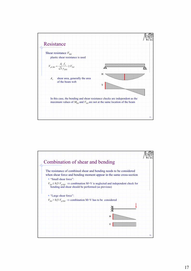
Resistance
Bending moment resistance MRd
the resistance is calculated for the corresponding class of the cross-section
Class 1,2
Class 3
Class 4
Wpl plastic section modulus
Wel elastic section modulus
Weff effective section modulus taking into accoun the effect of local buckling, details will not be given in FSTD
EdM
yplRd,pl M
fWM
0
EdM
yelRd,el M
fWM
0
EdM
yeffRd,b M
fWM
0
M
V
17
33
Resistance
Shear resistance VRd
plastic shear resistance is used
Av shear area, generally the area of the beam web
In this case, the bending and shear resistance checks are independent as the maximum values of MEd and VEd are not at the same location of the beam
EdM
yvRd,pl V
fAV
03
M
V
34
Combination of shear and bending
The resistance of combined shear and bending needs to be considered when shear force and bending moment appear in the same cross-section “Small shear force”:
VEd 0,5 Vpl,Rd combination M+V is neglected and independent check for bending and shear should be performed (as previous)
“Large shear force”:
VEd > 0,5 Vpl,Rd combination M+V has to be considered
M
V
18
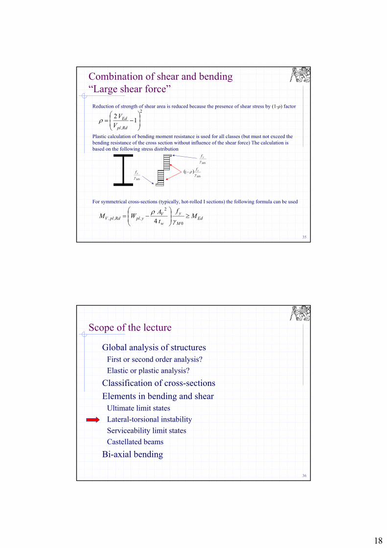
35
Reduction of strength of shear area is reduced because the presence of shear stress by (1-ρ) factor
Plastic calculation of bending moment resistance is used for all classes (but must not exceed the bending resistance of the cross section without influence of the shear force) The calculation is based on the following stress distribution
For symmetrical cross-sections (typically, hot-rolled I sections) the following formula can be used
Combination of shear and bending“Large shear force”
2
12
Rd,pl
Ed
V
V
EdM
y
w
Vy,plRd,pl,V M
f
t
AWM
0
2
4
0M
yf1
0M
yf
0M
yf
36
Scope of the lecture
Global analysis of structuresFirst or second order analysis?
Elastic or plastic analysis?
Classification of cross-sections
Elements in bending and shearUltimate limit states
Lateral-torsional instability
Serviceability limit states
Castellated beams
Bi-axial bending
19
37
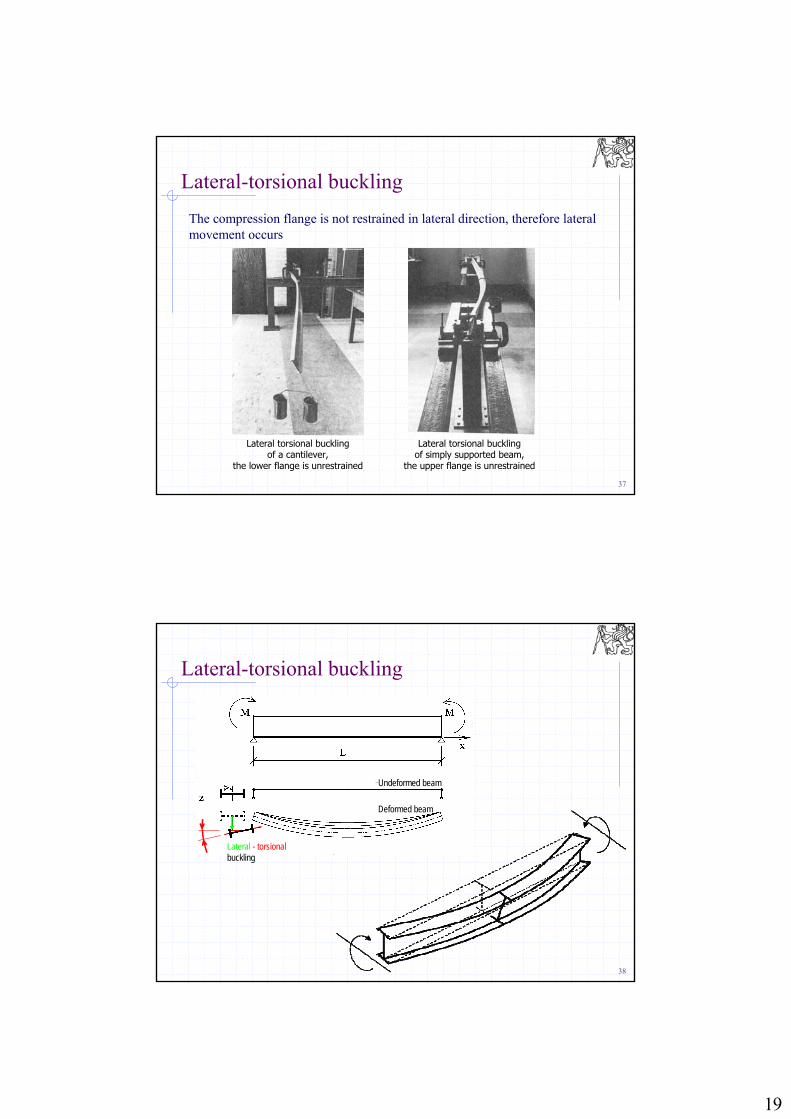
Lateral-torsional buckling
The compression flange is not restrained in lateral direction, therefore lateral movement occurs
Lateral torsional buckling of a cantilever,
the lower flange is unrestrained
Lateral torsional buckling of simply supported beam,
the upper flange is unrestrained
38
Lateral-torsional buckling
Undeformed beam
Deformed beam
Lateral - torsional buckling
20
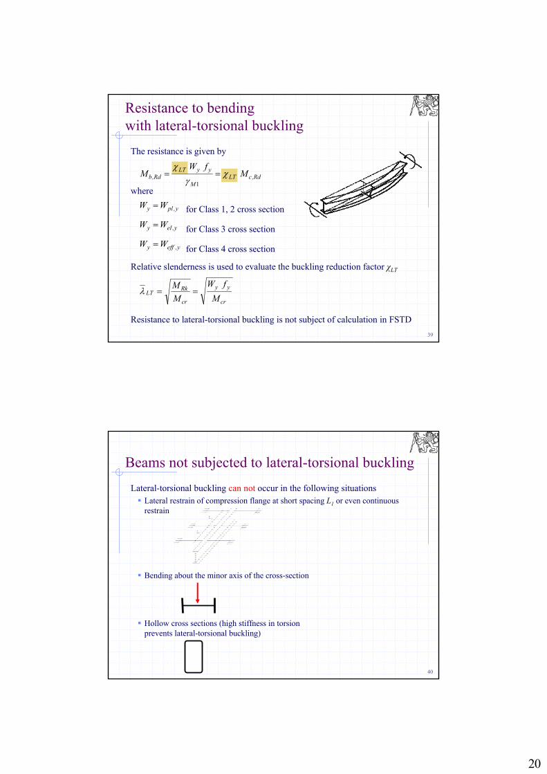
39
Relative slenderness is used to evaluate the buckling reduction factor χLT
Resistance to lateral-torsional buckling is not subject of calculation in FSTD
Rd,cLTM
yyLTRd,b M
fWM
1
Resistance to bending with lateral-torsional buckling
for Class 1, 2 cross section
for Class 3 cross section
for Class 4 cross section
y,ply WW
y,effy WW
y,ely WW
cr
yy
cr
RkLT
M
fW
M
M
The resistance is given by
where
40
Lateral-torsional buckling can not occur in the following situations Lateral restrain of compression flange at short spacing L1 or even continuous
restrain
Bending about the minor axis of the cross-section
Hollow cross sections (high stiffness in torsion prevents lateral-torsional buckling)
Beams not subjected to lateral-torsional buckling
21
41
Selection of section for beams
Hot-rolled sections are preferred (approx. to 400 mm height) IPE or I sections are the best choice, they are optimized for beams
In cases when the beams are not restrained in lateral direction (lateral torsional instability), wide flange sections are used (HEA)
Welded sections are slender and result in lower weight of the structure, they are designed for beams higher than approx. 600 mm
HEB sections are not good choice, they are good for columns
Choice of steel properties: When resistance governs, high yield limit fy is convenient to get smaller sections
and therefore lower weight use higher steel grade (S355, S420, S460)
When deflection governs, high yield limit has no effect as the deflection depends on modulus of elasticity E use standard steel grades (S235, S275) which is cheaper than high strength steel
42
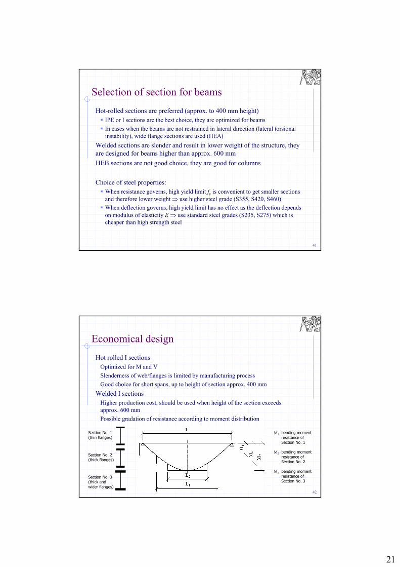
Economical design
Hot rolled I sections Optimized for M and V
Slenderness of web/flanges is limited by manufacturing process
Good choice for short spans, up to height of section approx. 400 mm
Welded I sections Higher production cost, should be used when height of the section exceeds approx. 600 mm
Possible gradation of resistance according to moment distribution
Section No. 1(thin flanges)
Section No. 2(thick flanges)
Section No. 3(thick and wider flanges)
M1 bending moment resistance of Section No. 1
M2 bending moment resistance of Section No. 2
M3 bending moment resistance of Section No. 3
22
43
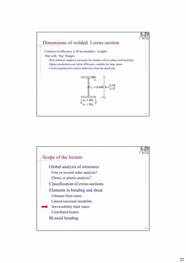
Dimensions of welded I cross-section
Criterion of efficiency is W/m (modulus / weight)
Thin web, “big” flangesWeb stiffeners might be necessary for slender web to reduce web buckling
Higher production cost, better efficiency, suitable for large spans
Can be chambered to reduce deflection from the dead load
44
Scope of the lecture
Global analysis of structuresFirst or second order analysis?
Elastic or plastic analysis?
Classification of cross-sections
Elements in bending and shearUltimate limit states
Lateral-torsional instability
Serviceability limit states
Castellated beams
Bi-axial bending
23
45
Serviceability limit states
Deflections are limited for aesthetic reasons
can be also a source of problems: cracks in brick walls, floor and wall tiles, glass façade and other brittle elements
shear deformation can be neglected in most cases
deflection caused by non-uniform temperature must be considered
Vibrations lead to discomfort of people using the building
46
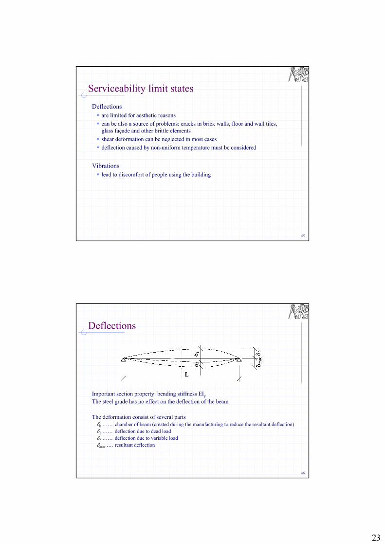
Deflections
Important section property: bending stiffness EIy
The steel grade has no effect on the deflection of the beam
The deformation consist of several parts0 …… chamber of beam (created during the manufacturing to reduce the resultant deflection)1 …… deflection due to dead load2 …… deflection due to variable load max …. resultant deflection
24
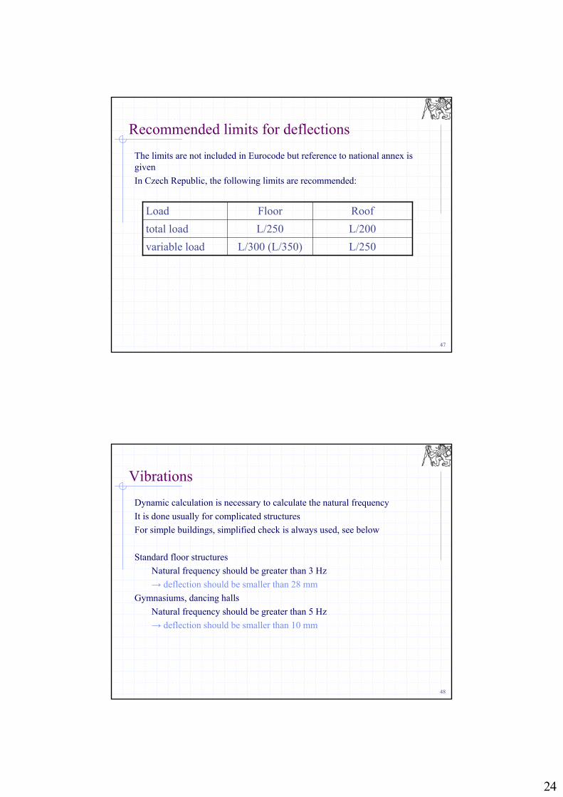
47
Recommended limits for deflections
The limits are not included in Eurocode but reference to national annex is given
In Czech Republic, the following limits are recommended:
L/250L/300 (L/350)variable load
L/200L/250total load
RoofFloorLoad
48
Vibrations
Dynamic calculation is necessary to calculate the natural frequency
It is done usually for complicated structures
For simple buildings, simplified check is always used, see below
Standard floor structures
Natural frequency should be greater than 3 Hz
→ deflection should be smaller than 28 mm
Gymnasiums, dancing halls
Natural frequency should be greater than 5 Hz
→ deflection should be smaller than 10 mm
25
49
Scope of the lecture
Global analysis of structuresFirst or second order analysis?
Elastic or plastic analysis?
Classification of cross-sections
Elements in bending and shearUltimate limit states
Lateral-torsional instability
Serviceability limit states
Castellated beams
Bi-axial bending
50
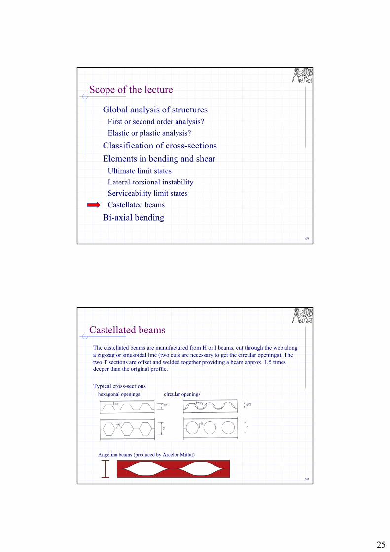
The castellated beams are manufactured from H or I beams, cut through the web along a zig-zag or sinusoidal line (two cuts are necessary to get the circular openings). The two T sections are offset and welded together providing a beam approx. 1,5 times deeper than the original profile.
Typical cross-sectionshexagonal openings circular openings
Angelina beams (produced by Arcelor Mittal)
Castellated beams
26
51
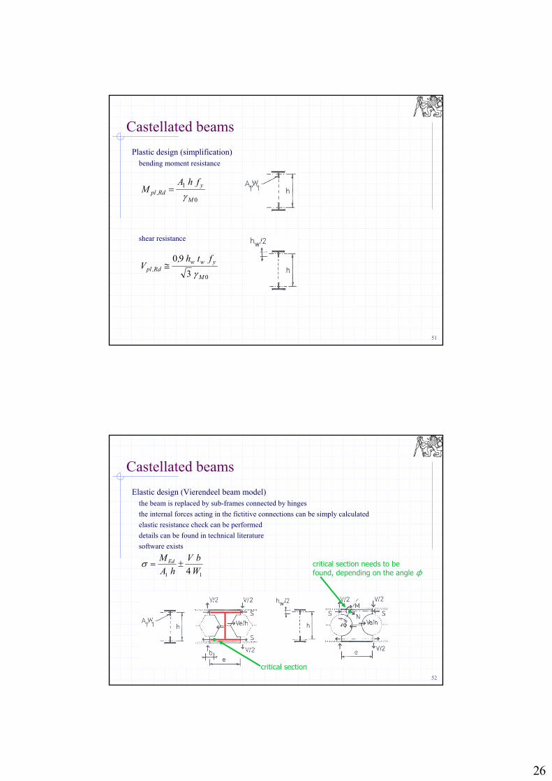
Plastic design (simplification)bending moment resistance
shear resistance
Castellated beams
0
1
M
yRd,pl
fhAM
03
90
M
ywwRd,pl
fth,V
52
Elastic design (Vierendeel beam model)the beam is replaced by sub-frames connected by hinges
the internal forces acting in the fictitive connections can be simply calculated
elastic resistance check can be performed
details can be found in technical literature
software exists
Castellated beams
11 4 W
bV
hA
M Ed
critical section
critical section needs to be found, depending on the angle ф
27
53
Scope of the lecture
Global analysis of structuresFirst or second order analysis?
Elastic or plastic analysis?
Classification of cross-sections
Elements in bending and shearUltimate limit states
Lateral-torsional instability
Serviceability limit states
Castellated beams
Bi-axial bending
54
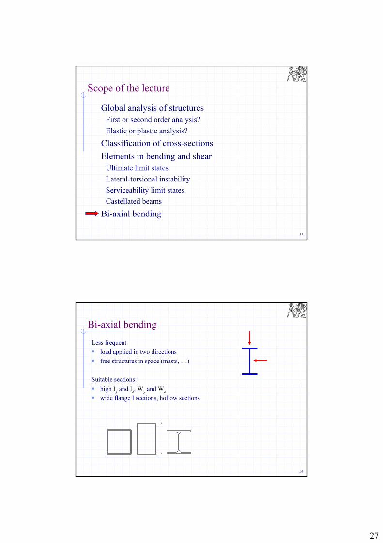
Bi-axial bending
Less frequent
load applied in two directions
free structures in space (masts, …)
Suitable sections:
high Iy and Iz, Wy and Wz
wide flange I sections, hollow sections
28
55
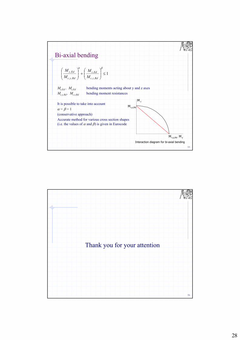
Bi-axial bending
1
Rd,z,c
Ed,z
Rd,y,c
Ed,y
M
M
M
M
My,Ed , Mz,Ed bending moments acting about y and z axes
Mc,y,Rd , Mc,z,Rd bending moment resistances
It is possible to take into account
= = 1
(conservative approach)
Accurate method for various cross section shapes (i.e. the values of and ) is given in Eurocode
Interaction diagram for bi-axial bending
c,z,RdM
c,y,RdM
zM
yM
56
Thank you for your attention