Embed Size (px)
Citation preview

ANUFPP/TM-296
PHYSICS OF COLLISIONLESS SCRAPE-OFF-LAYER
PLASMA DURING NORMAL AND OFF-NORMAL
TOKAMAK OPERATING CONDITIONS
by
Ahmed Hassanein
Isak Konkashbaev
March 1999
FUSION POWER PROGRAM@H ~ .... . ..
@
:.,.* J“””“-..~~.. ~’a Operated by%“’”’”” “~”“’”<’*A Argonne National Laboratory -The University of Chicago
ANL 9700South Cass Avenue forthe U.S. Department of EnergyArgonne, Illinois 60439 under Contract ~+11-109-Eng-38,,

Argonne National Laboratory, with facilities in the states of Illinois and Idaho, isowned by the United States government, and operated by The University of Chicagounder the provisions of a contract with the Department of Energy.
DISCLAIMERThisreportwaspreparedas an accountof worksponsoredby an agencyofthe UnitedStates Government.Neither the United States Governmentnoranyagencythereof,noranyoftheiremployees,makesanywarranty,expressor implied,or assumesany legal liabilityor responsibilityfor the accuracy,completeness,or usefulnessof any information,apparatus,product,or pro-cessdisclosed, or representsthat its usewouldnot infringeprivatelyownedrights. Referenceherein to any specif3ccommercialproduct, process, orservice by trade name, trademark,manufacturer,or otherwise,does notnecessarily constitute or imply its endorsement, recommendation, orfavoringby theUnitedStatesGovernmentor anyagencythereof.Theviewsand opinionsof authorsexpressedhereindo not necessarilystate or reflectthose of the UnitedStatesGovernmentor any agencythereof.
Reproducedfromthe best availablecopy.
Availableto DOEand DOEcontractorsfrom theOfficeof ScientitlcandTechnicalInformation
P.O. BOX 62OakRidge,TN 37831
Pricesavailablefrom (423)576-8401
Availableto the public from theNationalTechnicalInformationService
U.S. Departmentof Commerce5285Port RoyalRoad
Springfield,VA 22161

Distribution Category:Magnetic Fusion Reactor Materials
ANL/FPP/TM-296
ARGONNE NATIONAL LABORATORY9700 South Cass AvenueArgonne, Illinois 60439
Physics of Collisionless Scrape-Off-Layer Plasma duringNormal and Off-Normal Tokamak Operating Conditions
by
Ahmed HassaneinFusion Power Program
Energy Technology DivisionArgonne National Laboratory
Isak KonkashbaevTroitsk Institute for Innovation and Fusion Research, Troits~ Russia
March 1999
Work supported by theOffice of Fusion Energy
U.S. Department of EnergyUnder Contract W-3 1-109-Eng-38

DISCLAIMER
Portions of this document may be illegibJein electronic image products. Images areproduced from the best available originaldocument.
Physics of CoI1isionIess Scrape-Off-Layer Plasma during Normal
and Off-Normal Tokamak Operating Conditions
A. Hassanein* and I. IL Konkashbaev**
*Argonne National Laboratory, Argonne, IL, 60439, USA
**Troitsk Institute for Innovation and Fusion Research, Troitsk, Russia
Abstract
The structure of a collisionless scrape-off-layer (SOL) plasma in tokamak reactors is being
studied to define the electron distribution function and the corresponding sheath potential
between the divertor plate and the edge plasma. The collisionless model is shown to be valid
during the thermal phase of a plasma disruption, as well as during the newly desired low-
recycling normal phase of operation with low-density, high-temperature, edge plasma conditions.
An analytical solution is developed by solving the Fokker-Planck equation for electron
distribution and balance in the SOL. The solution is in good agreement with numerical studies
using Monte-Carlo methods. The analytical solutions provide an insight to the role of different
physical and geometrical processes in a collisionless SOL during disruptions and during the
enhanced phase of normal operation over a wide range of parameters.

I. Introduction
The steady operation of a plasma device is largely determined by the boundary conditions
at the divertor or the limiter plates. The plasma processes at these boundary walls are complex
and usually require extensive numerical simulation codes to obtain an insight into the relative
importance of the different interaction phenomena and the desired optimal conditions for
enhanced operations. The divertor plate, for example, in fiture fusion power machine is a key
component in removing particle and heat fluxes. In conventional divertor operation of existing
tokamaks, as well as in ITER-like device [1], the plasma in the scrape-off layer (SOL) is highly
collisional (T= 100 eV), i.e., the particle mean flee path, X, is much shorter than the parallel or
longitudinal distance, L, of the SOL between the two opposite (inner and outer) divertor plates.
During normal operation of these devices, power to the divertor plates usually does not exceed
the critical values at which melting or sublimation can occur. However, during plasma instabilities
such as hard disruptions, edge-localized modes (ELMs), and vertical displacement events
(VDES), the high incident power, W~, from the SOL (W~ 2107 W/cm2) will cause significant
erosion of the divertor plate and nearby components fi-om surface vaporization, melt-layer
splashing, and possible brittle destruction of carbon-based materials (CBMS) [2]. Although the
actual heat flux arriving at the divertor plate during these events is significantly reduced due to the
self-shielding effect from the divertor’s own eroded material, the net erosion depth can still exceed
hundreds of micrometers per event, which would lead to serious lifetime issues for these
components [3]. From such numerical simulations and modeling experiments, the erosion lifetime

of the divertor plate material has been found to depend on both the magnitude of the incident heat
flux from the SOL and the energy distribution of ion/electron fluxes to the divertor plate.
Therefore, for more accurate predictions of plasma instability effects and for better-designed
laboratory simulation experiments, a good knowledge of SOL physics and parameters is strongly
needed.
During various plasma instability events, the loss of confinement will cause the majority
of the core particle-flux, to arrive at the SOL with a relatively high temperature, T = TOwhere TO
(20-30 keV) is the core plasma temperature. This is in contrast to the normal operation scenario
in which the escaping particles from the core plasma to the SOL have a relatively lower
temperature, T S 1 keV and the plasma is collisional. Because of the high temperature of the
escaping particles during plasma instability events, the SOL plasma becomes collisiordess and
requires different treatment than that of SOL behavior during normal operation [4].
Collisionless SOL plasma behavior is also encountered during the normal phase of
operation with enhanced confinement [5,6]. This plasma operation with low particle recycling
and high temperature near the divertor plate was demonstrated during recent device discharges of
the JT-60U with the use of a boron-coated walls [7]. The plasma temperature in the SOL can be
several keV, which will result in a collisionless plasma condition. The collisionless behavior of
SOL during similar normal operations of large helical fision devices with enhanced particle
confinement was recently studied by numerical simulation with Monte Carlo methods [8].
3

We should emphasize that the term “collisionless” used in this report does not mean that
collisions can always be neglected. The term is used only to indicate that the particle path length
is much greater than the length of the SOL, i.e., the distance between the two opposite divertor
plates along magnetic field lines. The fill solution of the particle kinetic equation is still required,
however, to describe particle distribution functions in the SOL. This is because particles that
oscillate between plates located at distances much shorter than particle path length (collisionless
in space) will have lifetimes determined by collisions (collisional in time). Similar situations exist
in other plasma systems such as open magnetic traps and trapped particles in toroidal systems.
One of the main features of the collisionless SOL plasma is that the edge plasma acts as an
electrostatic trap for electrons, since electrons which originally have parallel energy that is lower
than the wall potential energy will be trapped between the inner and outer divertor plates. In a
collisional SOL, however, because of the short path length of both ions and electrons,
neutralization of the ion charge is due mainly to the SOL electrons moving toward the divertor
plate. Therefore, in contrast to the collisional SOL, charge neutralization of ions in collisionless
SOL plasma (see above deftition) occurs mainly due to these trapped electrons. In more recent
analyses, collisionless SOL plasma was studied (see, for example, Ref. 9) but without taking into
account trapped particles oscillating between the two negatively charged inner and outer divertor
plates. In this case, the full kinetic equation was not required. However, as will be shown below,
the existence of trapped particles is very important and requires the fill solution of the kinetic
equation of particle transport, which will result in different SOL major parameters such as
II
4
negative potential and net heat load to divertor plates. More details on the origin and dynamics
of trapped electrons can be found in Ref. 8.
II. Model Description of Collisionless SOL plasma
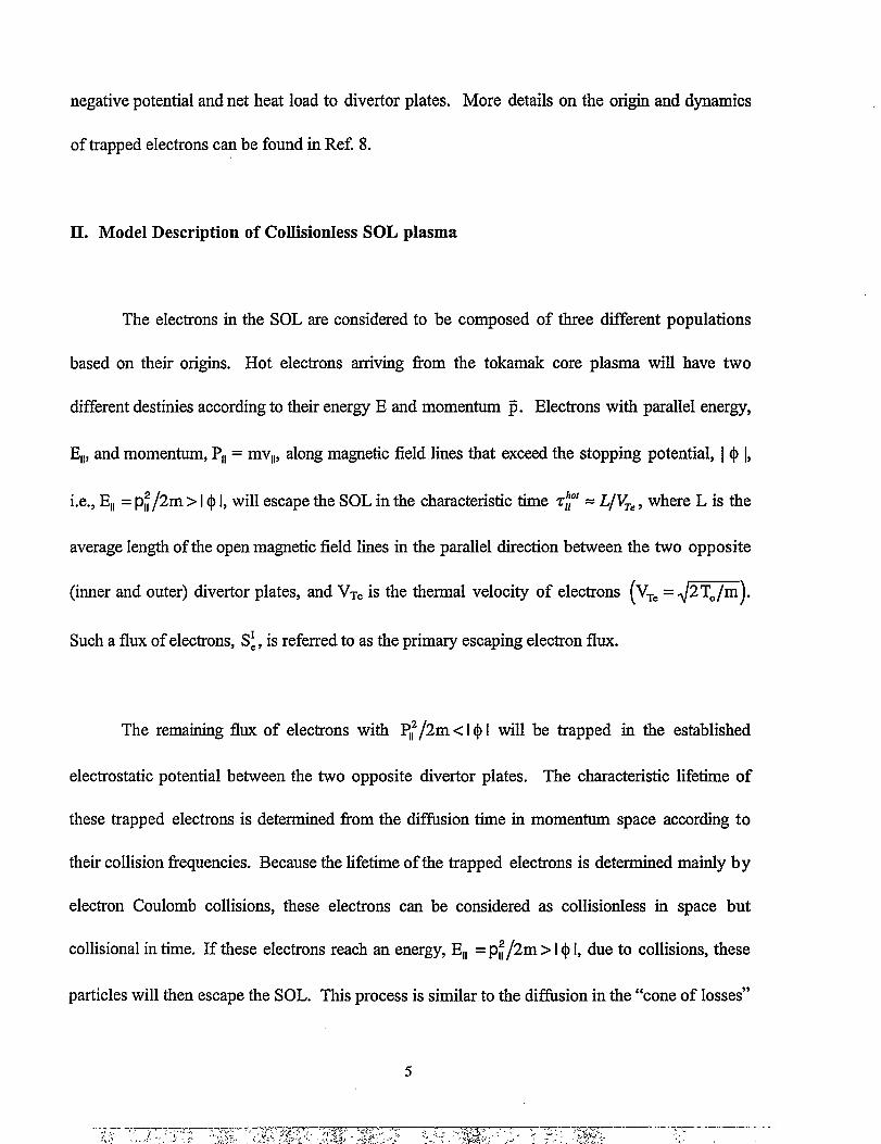
The electrons in the SOL are considered to be composed of three different populations
based on their origins. Hot electrons arriving from the tokamak core plasma will have two
different destinies according to their energy E and momentum ~. Electrons with parallel energy,
E,,, and momentum, PI,= mvll, along magnetic field lines that exceed the stopping potential, I ~ 1,
i.e., El, = p~/2m > I~ 1,will escape the SOL in the characteristic time zy = L/VTe, where L is the
average length of the open magnetic field lines in the parallel direction between the two opposite
(inner and outer) divertor plates, and V~Cis the thermal velocity of electrons (V=.= ~~).
Such a flux of electrons, S:, is referred to as the primary escaping electron flux.
The remaining flux of electrons with ~~/2m < I@I will be trapped in the established
electrostatic potential between the two opposite divertor plates. The characteristic lifetime of
these trapped electrons is determined from the diffusion time in momentum space according to
their collision frequencies. Because the lifetime of the trapped electrons is determined mainly b y
electron Coulomb collisions, these electrons can be considered as collisionless in space but
collisional in time. If these electrons reach an energy, El, = p~/2m >1@1,due to collisions, these
particles will then escape the SOL. This process is similar to the diffusion in the “cone of losses”
5

in the mirror trap devices. The flux of escaping electrons is referred to as the secondary escaping
electron flux.
The third electron population in the SOL is that of the so-called “cold” electrons, which
arrive from the divertor plates. This cold electron flux emitted fi-om one wall (divertor plate) will
pass through the SOL and be absorbed by the opposite wall. Therefore, the net current of the
cold electrons is equal to zero (in a symmetrical SOL) since a similar value of cold electrons flux is
emitted in the opposite direction by the other divertor plate. Residence time of these cold
electrons in the SOL can be estimated by &d = L/~, where VC= ~-, which is similar to
VTCsince eq = KTO;therefore their residence time is also much less than the electron collision
time and such electrons can also be regarded as fully collisionless. A schematic illustration of the
various electron populations in a collisionless SOL plasma is shown in Fig. 1.
Because the potential, @,changes rapidly only in a very small region near the divertor
plates (walls) with width AL<<L (as shown schematically in Fig. 2), a simple one-dimensional
representation of the potential function can be given by:
() (x)= -(j. x=O, L
@(x)=o O< X<L.
(2-1)
I. I
6

This means that the SOL plasma can be regarded as a homogeneous plasma region along the
magnetic field lines. In this study, we also assume that the SOL plasma is homogeneous across
the magnetic field lines. Nonhomogeneous effects in the SOL plasma will be considered in a
followup study.
The trapped electrons in the SOL, i.e., with El,< e& will move between the two opposite
divertor plates with a bouncing flequency, f~, given by
fE=+=. (2-2)
Different electron bouncing frequencies will result in “phase-mixing” of the electrons and
therefore the distribution of these electrons can be considered as homogeneous in space. Due to
Coulomb collisions, the electron diffhsion takes place along the Vll axis in the momentum space.
The lifetime of these trapped electrons, z?, to escape the SOL can be estimated by z~ = ~,~,
where ZCCis the electron/electron Coulomb collision time. The escaping electron flux due to these
collisions is referred to as the secondary escaping electron fl~ S:. The third electron
population in the SOL, i.e., the “cold” or “secondary” electrons is emitted by the wall such that:
(2-3)
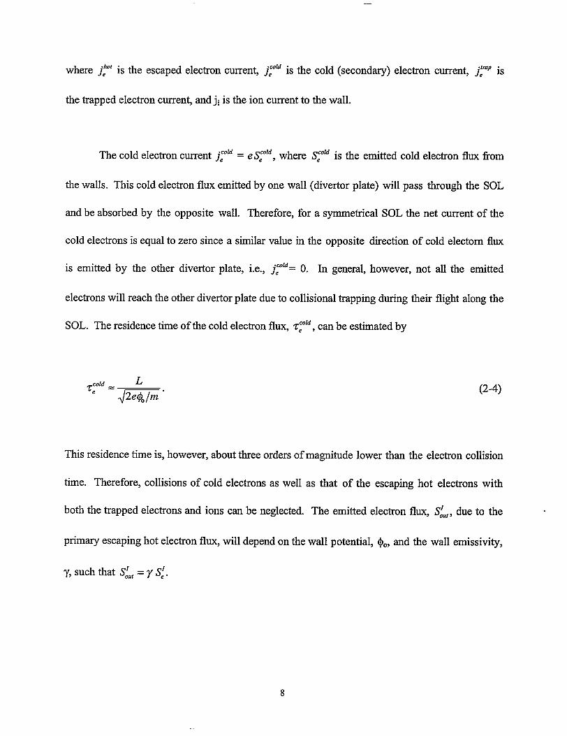
where jfl is the escaped electron current, j~” “1s the cold (secondary) electron current, j~ is
the trapped electron current, and -jiis the ion current to the wall.
The cold electron cument j~” = e S~ld, where S~” is the emitted cold electron flux from
the walls. This cold electron flux emitted by one wall (divertor plate) will pass through the SOL
and be absorbed by the opposite wall. Therefore, for a symmetrical SOL the net current of the
cold electrons is equal to zero since a similar value in the opposite direction of cold electorn flux
is emitted by the other divertor plate, i.e., j~”= O. In general, however, not all the emitted
electrons will reach the other divertor plate due to collisional trapping during their flight along the
SOL. The residence time of the cold electron flux, z~”, can be estimated by
‘:”=&“ (2-4)
This residence time is, however, about three orders of magnitude lower than the electron collision
time. Therefore, collisions of cold electrons as well as that of the escaping hot electrons with
both the trapped electrons and ions can be neglected. The emitted electron flux, S~U,,due to the
primary escaping hot electron flux, will depend on the wall potential, $., and the wall emissivity,
y, such that S~U,= y S:.

The ion current, ji, in the SOL is equal to the ion current arriving from the core plasma.
The average ion velocity Vi in the SOL is approximately similar to mat Of the thermal ion
velocity Vn:
where M is the average ion mass. The residence time of these ions in the SOL is given by
where & is again the characteristic time of the escaping hot electrons in the SOL.
(2-5)
(2-6)
Near the wall where the potential is sharply decreased from O to +., the ions are
accelerated to a velocity given by
(2-7)
However, within the developed model of a homogeneous SOL plasma, one can neglect this
acceleration because it will not significantly influence the main results, as will be shown later.

During normal operation, as well as during disruptions, two types of heat fluxes arrive at
the SOL from the core plasma: particle heat flux, WP, carried by the lost particle fluxes of both
electrons (SC)and ions (Si ) and heat flux, Wk, due to heat diffhsion. The particle fluxes SC,i
usually have an ambipolar nature; therefore:
se = Si = sin,
The value of Sin can be estimated as
Sin = ‘0.2nR.‘r2j‘P
where R is the major radius, r is the minor radius, ~ is core plasma density,
cordlnement time. The corresponding
flux, W~, is estimated as
(2-8)
(2-9)
and ZPis the particle
particle heat flux is WP=3KT0 Sin . The conduction heat
Qowk.—, and Q. = no.3KT.2nR.nr2,~k
(2-lo)
where ‘tk is the characteristic time of heat loss due to conduction and K is Boltzmann’s constant.
The total heat flux W. arriving at the SOL can therefore be estimated as
10
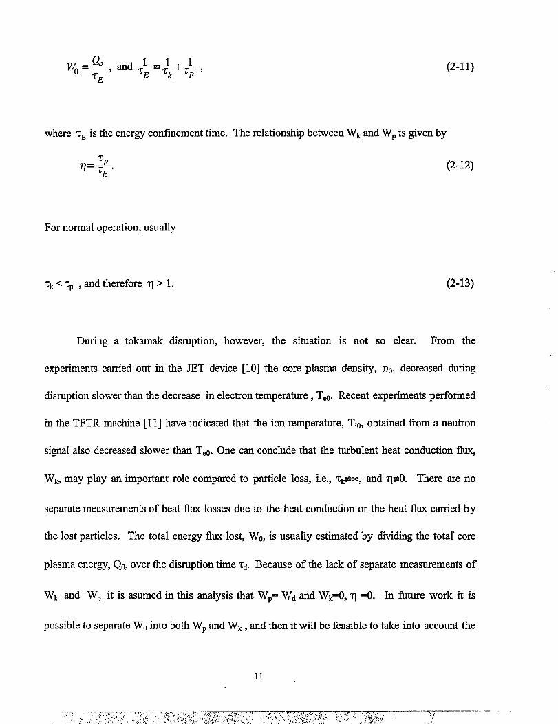
w, Q o and 111=—, —=—‘E ‘k
+= ‘‘E
(2-11)
where t~ is the energy confinement time. The relationship be~een Wk ~d WP iS given by
~Pq=~. (2-12)
For normal operation, usually
(2-13)& < ~p , and therefore ‘q>1.
During a tokamak disruption, however, the situation is not so clear. From the
experiments carried out in the JET device [10] the core plasma density, ~, decreased during
disruption slower than the decrease in electron temperatui-e, T@. Recent experiments petiormed
in the TFTR machine [11] have indicated that the ion temperature, Tie, obtained from a neutron
signal also decreased slower than TCO.One can conclude that the turbulent heat conduction fl~
Wk, may play an important role compared to particle loss, i.e., &#oo, and q#O. There are no
separate measurements of heat flux losses due to the heat conduction or the heat flux carried b y
the lost particles. The total energy flux lost, Wo, is usually estimated by dividing the total core
plasma energy, Qo, over the disruption time z~. Because of the lack of separate measurements of
Wk and Wp it is asumed in this analysis that Wp= Wd and Wk=(), ‘q =0. h future work it is
possible to separate W. into both Wp and Wk, and then it will be feasible to take into account the

effect of heat conduction. In section V it will be shown how both WP and Wk can be considered
separately.
The ion density, W, in the SOL can be estimated from the stationary condition that
S~l= Sin,where the ion flux, S~l, from the SOL to the divertor plate is given by
(2-14)
where h is the SOL width, Bq, and Be are the mean values of the poloidal and toroidal magnetic
fields in the SOL respectively. The q. value depends on the specific tokamak geometry and is
usually close to unity in the SOL and is assumed equal to 1 in this analysis. Therefore ~ is given
by
-&%ni =VmhzP ‘o.
(2-15)
The total electron density in the SOL is the sum of all densities of the three different electron
populations defined above. The total flux of the cold electrons, S~~, is defined by
12
(2-16)

where y is again the wall emissivity of the secondmy electrons.
The condition of quasineutrality of the SOL plasma is given by
where n)**are the densities of the primary and secondary escaping electrons, respectively, n~
is density of the trapped electrons, and n~” is the density of the cold electrons.
In a collisionless SOL, the trapped electron density is much higher than in a collisional
SOL plasma due to the very low density of both the escaping and cold electron populations in
the collisionless layer. For typical parameters of V=. (10 kev) = 6 x 10⁹cmk, R -10 m, r -1 ~
and h = 3 cm, the escaping-electron density is
#,11 ~s:,II
e VT,2zrh ‘no v..;~zp <<no. (2-18)
For the same reason, the resulting cold electron density is also low. Therefore, the positive ion
charge is neutralized mainly by the negative charge of the trapped electrons, and
(2-19)
J—. .
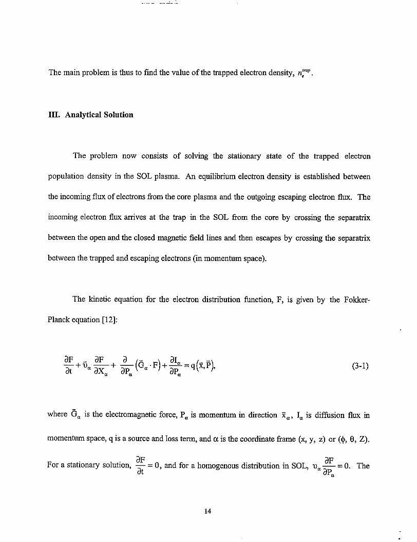
The main problem is thus to find the value of the trapped electron density, n~mp.
III. Analytical Solution
The problem now consists of solving the stationary state of the trapped electron
population density in the SOL plasma. An equilibrium electron density is established between
the incoming flux of electrons from the core plasma and the outgoing escaping electron flux. The
incoming electron flux arrives at the trap in the SOL from the core by crossing the separatrix
between the open and the closed magnetic field lines and then escapes by crossing the separatrix
between the trapped and escaping electrons (in momentum space).
The kinetic equation for the electron distribution fhnction, F, is given by the Fokker-
Planck equation [12]:
(3-1)
where ~a is the electromagnetic force, Pa is momentum in direction Xa, Ia is difision flux in
momentum space, q is a source and loss term, and ct is the coordinate frame (~ y, z) or (~, (3, Z).
For a stationary solution,3F i3F— = O, and for a homogeneousdistribution in SOL, V. —at apa
= O. The
14
I. I

electric field effect is taken into account at the boundruy conditions. The magnetic field does not
affect the distribution function F. The vector I in Eq. 3-1 specifies the electron density flux in
momentum space arising from particle collisions. It is defined by
Ia=Aa F-DaP
where the vector ~ is the of dynamic friction
(3-2)
coefficient and the tensor Dap is the particle
diffhsion coefilcient in momentum space.
Figure 3 is a schematic illustration of the trapped-particle zones in momentum space.
Three regions are shown for different trapped particles in momentum space. Region I is occupied
with trapped particles having total energy less than that required to overcome the electrostatic
barrier at the walls. Region II is filled with particles having P > P* (P* = mv” = ~=). Only
scattering without energy exchange is sufilcient for the particles to escape this region. Region III
contains very low densities of escaping and cold electrons. One of the objectives of this work is
to find an analytical solution to easily study the dependence of the solution on device
characteristics (both physical and geometrical) in order to understand the significance and effect
of each parameter on the SOL characteristics. The analytical solution cm however, be obtained
using few assumptions. The validity and justification of these assumptions will be critically
assessed as we proceed to find the analytical solution.

The first assumption is that one can neglect the influence of particles in region II (Fig. 3).
This can be justified for several reasons. First, particles in region II can easily escape due to
scattering by both ions and electrons because these particles need only a change in their angular
momentum during a time t = Zu = ~,i. Such elastic collision processes are much faster than
particle diffhsion along the P-axis with increasing total momentum due only to electron scattering.
Another reason for neglecting the influence of particles in region II is because particles in this
region are in the nonequilibriurn state because (Pll) # (PL). For situations in which parallel
particle momentum does not equal perpendicular momentum, a “fire-hose” Alven wave
instability usually takes place with a maximum increment on the order of the ion gyrofi-equency,
@Bi,which is much greater than the characteristic time, ‘rC,[13], i.e,
@Bi % 108 Hz >>~ = 103 Hz.‘re
(3-3)
The resulting turbulence effect of this instability is to equalize (Pll) and (Pl ). In this case, it
means that additional transverse momentum, (Pl ), is transferred to parallel momentum, (Pll).
Therefore, particles in region II with their parallel momentum (Pll > P*) will escape. More
detailed description of the relaxation of such anisotropic distribution for homogeneous media is
given in [14].
16

By neglecting the contribution of particles in region II, we can reduce the problem to a
more simple one of particle diffbsion in region I along the axis P (see Fig. 4). Therefore, the
trapped-electron distribution function, F, is similar to that of the schematic illustration shown in
Fig, 5. The fi.mction F, for the reduced problem, does not depend on the angle 0, i.e., F is an
isotropic function. Therefore, Equation 3-1 is reduced to .
+ap2(D%-AF)l=-q(p’y(3-4)
where the source function, q, (per unit volume of phase space per second), the diffhsion
coefficient, D, and the dynamic friction, A, are also isotropic functions of P.
An exact solution of this problem is still difficult since the coefficients D of diffusion and
A of the dynamical friction are unknown but are needed for the solution to the distribution
function F. This means that the problem is highly nonlinear. Computer methods such as Monte-
Carlo can be used to solve this problem numerically [8]. However to obtain an analytical
solution, some arbitrary assumptions must be made. It will be evident, however, from the
developed solution that the basic features of the phenomenon will be not lost due to these
assumptions. A similar problem to estimate electron losses from open mirror traps was obtained
in the case of a large wall potential, Ie@cT I >>1 [15].

To obtain an analytical solution for the distribution fi.mction in the case considered, one
can use the diffusion approximation in which D and A are replaced by a known fi.mction of P. If
we allow both D and A to be represented
then seek the function, F, in the form
F= 1(27t)
~,z C~ of(P) e-p%,
by an expression for a Maxwellian velocity distribution,
(3-5)
where C~ is a constant that includes parameters from the source function q(P). Hereafter the
dimensionless momentum, P, and the dimensionless potential, Y?,are defined as
P=mV/PO , PO=~~ ,and ~=eqO/KTO (3-6)
The diffusion mechanism of particle losses results in a rather weak dependence of the normalized
wall potential, ~“, and the corresponding momentum, P* = ~2yJ* , on tokarnak parameters since
these effects are integrated over the velocity space which tends to average the detailed structure
the function F. Therefore, the obtained analytical solution is considered a good approximation
this problem. To calculate D and A, the function f(P) in Eq. 3-5 will be assumed equal to
therefore D and A are given by
D=v(P), A=–v(P). P,
of
to
1,
(3-7)
where v (P) is the dependence of the collisional frequency on P,
18

4n?m~ n~P
v(P) = = VOPO)++
m2V3 OP(3-8)
in which the unknown density, nfip , of the trapped electrons will be found from the solution.
The use of such assumption makes possible to find an analytical solution for this problem.
The source function q(P) is the electron distribution fiction arriving fi-om the core
plasma. Therefore, q(P) is taken to be a Maxwellian distribution. Finally, the dimensionless
equation for the electron distribution fimction F can be rewritten as
+W=+p’)l=-aq(p)>(3-9)
-P%
‘(p) = (27t;3/’ e ‘
The parameter a includes parameters of the tokamak device
()2
1 no &.— —a= 2~ vo~p n~p q
This form of equation has a solution in the form
[
&eP2/2 $(p)Cqe-P2’2 l-a.p+a~+a~‘= (2n;3/’ 3 1
where
19
(3-lo)
(3-11)

p ‘~2’2 d~ is the probability integral.o(~)”~~e
The constant C~is defined from the normalization condition
4Z~F(P)P2 dP=n~p ,
where n~p = n, according to Eq. 2-19. The value of P* can be found
condition F(P*) = O. The solution of this boundary equation and the
(3-12) 0
fi-om the boundary
dependence of the
normalized wall potential, v*, on the parameter, a, is found numerically, as shown in Fig.7. The
solution, however, has the following two asymptotes:
The parameter, a, defined from C~is also calculated numerically with the asymptotes:
(3-13)
(3-14)
20
(3-15)

%
P*+O; a+(~5)%*
[)
~PV.Oh
()2ZZ ?fl vOR2 r “ (3-16)
Thus the wall potential, @O,depends on tokamak dimensions (i.e., ~ r), on plasma density and
temperature via electron collision frequency, VO,on the thermal velocity of ions, Vfi, and on the
particle conilnement time, zP.
IV. Disruption Conditions
For fiture tokamak devices with major radius R = 6 m, minor radius r = 1 m, plasma core
temperature TO= 20 keV, and core density ~ = 1014cm-3,the disruption time, ~&is =1 ms. The
parameter, a, for such a device is calculated to be large, a = 20. This means that we can use the
asymptotic solutions given in Eq. 3-13 to estimate the wall potential. Therefore,
P*= 0.9 and yJ*= 0.5.
The density of the trapped electrons is therefore estimated as
n~p=3no .
(4-1)
(4-2)
The fraction, &of the incoming electrons that is trapped in the SOL is given by
21
I

P“
f‘p% P2 dp
~= :’ =0.3.
J e‘p% P2dp0
(4-3)
The temperature (mean energy), Tflp , of the trapped electrons in the SOL having the non-
Maxwellian distribution fimction of Eq. 3-9 is lower than the core temperature TO:
~trap=T~o~<y” To= 9 keV . (4-4)
IThe assumption of F (P=P*)= Omeans that all electrons leaving the trap will have P = P*,
which means that their energy at the wall, ET, after overcoming the stopping potential, $., is
equal to zero; i.e.,
E~=O. (4-5)
In reality, however, the distribution fi.mction, F, has a sharp “tail” at P > P*; therefore, electrons
diffising from the trap will also bring some energy flux to the wall. This heat flux is estimated to
be approximately equal to the escaping-electron heat flux. A more exact solution of the fill
problem is currently being pursued with numerical methods. A fill illustration of the electron
distribution fi.mction, F, is shown in Fig. 6. The main parts of F are the trapped electrons with
. I
22
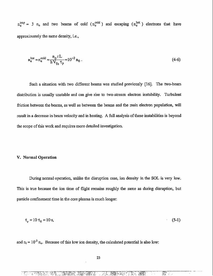
~trape = 3 u and two beams of cold (n~ld ) and escaping (n~ ) electrons that have
approximately the same density, i.e.,
nhot ~ ncold~ n rLe t?
hj ~ =10-2n0.Te P
(4-6)
Such a
distribution is
situation with two different beams was studied previously [16]. The two-beam
usually unstable and can give rise to two-stream electron instability. Turbulent
fiction between the beams, as well as between the beams and the main electron population, will
result in a decrease in beam velocity and in heating. A fill analysis of these instabilities is beyond
the scope of this work and requires more detailed investigation.
V. Normal Operation
During normal operation, unlike the disruption case, ion density in the SOL is very low.
This is true because the ion time of flight remains roughly the same as during disruption, but
particle confinement time in the core plasma is much longer:
‘TP =lO’CE=lOS,
and ni = 10-3~. Because of this low ion density, the calculated potential is also low:
23
~ (5-1)

P*= 0.4 and WO= 0.2. (5-2)
The above results are obtained assuming that the heat conduction flux from the core
plasma to the SOL is negligible. This assumption may be valid during the disruption scenario,
but during normal operation-even with enhanced confhernent-the conductive heat flux, Wk, can
exceed by one order of magnitude the heat flux, W~,carried by the plasma particles crossing the
separatrix:
W,=:kTOSin. ct
sin=~, u.= *<1,Tp o
(5-3)
where T~ is the temperature of the plasma crossing the separatrix. The ratio of the conductive
heat flux to the particle heat flux,&, is then given by
(5-4)
To account for the influence of heat conduction, one can assume that the conduction heat
flux is distributed among the trapped electrons [8]. This seems reasonable because the lifetime of
24

the trapped electrons is controlled by Coulomb collisions. Heating of the trapped electrons will
result in faster escape of trapped electrons by overcoming the confining potential. Additional
heating of the trapped electrons will therefore result in the requirement of a higher stopping
potential in order to neutralize the positive ion charge density, which is fixed by the negative
charge of the trapped electrons.
To analyze the effect of heat conduction on the trapped electron distribution fi.mction,
one can modify Eq. 3-8 to consider the incoming electrons as a Maxwellian distribution but with
an enhanced temperature by & times. Using this consideration, one can use all the previously
obtained results with the assumption that the ion temperature remains the same. This means that
the collision frequency, VO,must be reduced by & times. Therefore, the new parameters are
given by
(5-5)
From the above equations, the dimensionless potential, ~“, is decreased by ~~ times, but the
actual potential is increased:

40 %1—+6,=VOCS “
kTo(5-6)
For ZP = 10%~ and, et= 1, the value”of & = 20. Therefore,
(5-7)
This value of the wall potential during the enhanced phase of normal operation seems reasonable
and is in reasonable agreement with numerical Monte Carlo calculations [8].
In the above analysis, the coefficient of secondary electron emission is assumed equal to
1. This is true for the disruption case since the hot and dense vapor cloud that developed from
the wall because of plasma energy deposition has very high emissivity. Lower wall emissivity
will increase the stopping potential. The influence of the emissivity on the wall potential in a
collisionless SOL, however, was previously shown to be small [8].
The dynamic friction and diffision coei%cients were obtained in Eq. 3-5 with the
assumption of a Maxwellian distribution fimction of the trapped electrons with T = TO.
However, it was shown fi-omEq. 4-1 that the actual temperature (or mean energy) of the trapped
electrons is lower than that, i.e., ~ < e@O/kTo = 0.5 To. Because $0 depends only weakly on Tt (00
26

Oc T-xl), the accuracy of these assumptions for this study seems acceptable in order to
understand the general dependence of device parameters on a collisionless SOL.
The inclusion of particles in region II (see Fig. 3) should decrease the wall potential due to
the increased phase space area of the trapped electrons. This is a result of the additional
diffusion time required for the particles to leave region II and escape to the wall. Decreasing of
the flux of the trapped electrons, i.e., increasing the escaping flux, will decrease the wall potential,
I$1. Therefore, slightly better conilnement of the trapped particles is expected.
No sufficient data are available on the ratio of the thermal and particle fluxes arriving from
the core plasma during plasma disruptions. Conventional opinion assumes that the heat flux,
Wk= kVT, is equal to zero, and this assumption is also used in this study. However, recent data
from current tokamak machines such as JET indicate that the thermal phase of a plasma
disruption can be divided into two stages [10]. First, there is a slow decrease in T. during about
70% of the disruption phase, followed by a fast decrease of T. almost to zero during the
remaining part of the thermal phase of disruption. This may suggest that heat conduction during
a disruption could play a role in the dynamics of SOL parameters.
IV. Summary

During conventional divertor operations, the plasma in the scrape-off layer (SOL) is
highly collisional. However, anew divertor operational scenario with high-temperature, low-
density plasma has been proposed to enhance energy confinement in helical devices and in
tokamak machines. Therefore, the study of a collisionless high-temperature, low-densi~ SOL
plasma becomes important. In addition, the SOL plasma during disruptions in most fision
devices is always shown to be collisionless.
The collisionless SOL plasma during normal operations was recently studied in different
fusion devices. The main idea of these studies is that the ions and electrons coming from the core
plasma with similar fluxes (Si = SC= SiJ will leave the SOL with different flight times (lifetimes)
due to the large differences in their thermal velocities (V~~/V~i = ~~). For charge
neutralization, the existence of trapped electrons between the two opposite divertor plates is,
therefore required. The fact that a negative potential, $., exists between the SOL plasma and the
divertor walls (or the vapor cloud near the divertor plates during a disruption) actually means that
the SOL is the electrostatic trap for electrons. Ions, in contrast, are accelerated toward the walls.
Electrons arriving at the SOL will face two different fates. Electrons with parallel energy,
El,< e$o, are trapped and can leave the trap only due to collisions, i.e., difision in phase space.
The remaining electrons with El,> e$Owill quickly escape the SOL in z; time. A cold secondary
electron flux is emitted from the walls as a result of the fast-escaping electrons. Therefore, the
. I
28
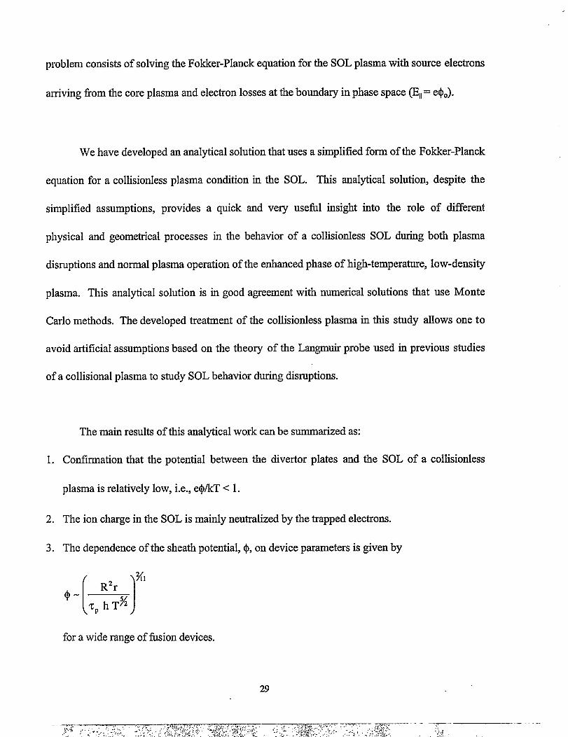
problem consists of solving the Fokker-Planck equation for the SOL plasma with source electrons
arriving from the core plasma and electron losses at the boundw in phase space @ll= e$o).
We have developed an analytical solution that uses a simplified form of the Fokker-Planck
equation for a collisionless plasma condition in the SOL. This analytical solution, despite the
simplified assumptions, provides a quick and very usefil insight into the role of different
physical and geometrical processes in the behavior of a collisionless SOL during both plasma
disruptions and normal plasma operation of the enhanced phase of high-temperature, low-density
plasma. This analytical solution is in good agreement with numerical solutions that use Monte
Carlo methods. The developed treatment of the collisionless plasma in this study allows one to
avoid artificial assumptions based on the theory of the Langmuir probe used in previous studies
of a collisional plasma to study SOL behavior during disruptions.
The main results of this analytical work can be summarized as:
1. Confirmation that the potential between the divertor plates and the SOL of a collisionless
plasma is relatively low, i.e., e$/kT <1.
2. The ion charge in the SOL is mainly neutralized by the trapped electrons.
3. The dependence of the sheath potential, $, on device parameters is given by
[)%1
0- “r,
Tp h TA
for a wide range of fhsion devices.

4. Electron distribution in the SOL includes four different electron beams (two hot electron
beams and two cold electron beams). Existence of such beams can result in two-stream
electron instability. The consequence of this turbulent instability is that the SOL plasma can
be collisional with the turbulent path length, k~, of the electron beams approximately the
same length as that of the SOL, i.e., &= L.
The analytical results obtained in this study were made possible only through some
simplified assumptions. More detailed considerations and more elaborate solutions that use
numerical methods for the nonlinear Fokker-Pkmck equation are required for a better and more
comprehensive understanding of the roles of all physical processes involved. Such a study is
currently underway.
Acknowledgments
This work is supported by the U.S. Department of Energy.
.
References
[1 R. Parker, G. Janeschitz, H. D. Pacher, D. Post, S. Chiocchio, G. Federici, P. Ladd, J.
Nuclear Materials, 241-243 (1997) 1.
[2] A. Hassanein, “Response of Materials to High Heat Fluxes during Operation in Fusion
Reactors,” ASME, 88-WA/NE-2 (1988).
[3] A. Hassanein and I. Konkashbaev, Plasma Devices and Operations, Vol. 5 (1998) 297.
30

[4]
[5]
[6]
[7]
[8]
[9]
[10]
[11]
[12]
[13]
[14]
I. K. Konkashbaev, Plasma Phys., Rep. 19 (8), Aug. (1993) 496.
N. Ohyabu, T. Watanabe, H. Ji, H. Akao, et al., Nucl. Fusion 34 (1994) 387.
H. Takase and N. Ohyabu, Nucl. Fusion 35 (1995) 123.
M. Shimada and JT-60 TEAM, 14ti Int. Conf. on Plasma Physics and Controlled Nuclear
Fusion Research, Wurzburg, Germany, 30 Sept.-7 Oct., 1992, IAEA, Vie- Vol. 1, p. 57
(1993).
W. X. Wang, M. Okamoto, N. Nakajima, S. Murakami, N. Ohyabu., Nucl. Fusion 37
(1997) 1445.
P. J. Catto and R. D. Hazeltine, Phys. Plasmas 1 (6) (1994) 1882.
D. J. Ward and J. A. Wesso~ Nuclear Fusio~ Vol. 32. No. 7 (1992) 1117.
V. V. Mirnov, Private Communication, 1997.
D. V. Sivukhin, Reviews of Plasma Physics, Vol. 4, M. A. Leontovich, cd., Consultants
Bureau, New York (1966).
N. A. Krall and A. W. Trivelpiece, Principles of Plasma Physics, McGraw-Hill (1968).
M. N. Rozenbluth and R. Z. Sagdeev, Handbook of Plasma Physics, Vol. II, General
Editions, North-Holland (1980).
[15] V. P. Pastukhov, Reviews of Plasma Physics, Vol. 13, B. B. Kadomtsev, cd., Consultants
Bureau, New York-London (1987).
[16] I. K. Konkashbaev and A. P. Ponomarev, Sov. Plasma Physics, Vol. 16 No. 1 (1990) 3.

s’u ‘// / / ..-.:. :..... “*”.”: ““”.-.. \i\\
\\\ESCAPING
ELECTRONS //7’
J!’)Ix(($EiCL SHEATH POTEN
z1
9f=
INNERDIVERTO
OUTER
PLATEERTORATE
TIAL
Fig.1 Schematic illustration of electron population in acollisionless SOL between inner and outer divertorplates in a tokamak device

INNER PLAIE
TRAPPED ELEclRoNs
$- !+1 + + R=AL -1+-
SEPARATRIXC!X?E’ PLAS!MA
Fig.2 Schematic view of different electron populationsin SOL described in the used model

—
cos e
I11 -.. 1 k ——. . —a
J “x”/s III
I. ...’ ..’ ..”.”. . . . .. . ‘. . .. ’ . ; : .’.:....- .“” h“.. .
. ..*-.. ““’.
IQ,.. ‘.. . ,.
. . . . . .. .. ’*. .e ‘.. , .
. . .“,,** . . . . . . . . . .
.) ]k::’: x”: ::”::”;:;”;” x“”~. .
“.I
-. ... *,“. ”....” .. ’...’. ‘-. -.. ., D“.. ,,. . . . . . .. “.. .,.. .
. . . . . . . “.. .,. .,.. . . I ‘.. ““”-. . ...,. .. ...*. -. .
Of-”’---++””* .“O ---1 P P
Fig.3 Regions of trapped electrons in momentumspace

cos e
ITRAPPED I ESCAPING
PARTICLES I PARTICLES
o1 P
Fig.4 Trapped electrons in momentum space forreduced problem

I
F
(DISTRIBUTION FUNCTION)
\
I
‘\ IFt
TRAPPEDELECTRONS \
‘iI\@xwdmm
\
.
Fig.5 Distribution function of trapped electronsin SOL, compared to a Maxwelliandistribution function

I
F ~C~~DISTRIBUllONFuNcnoNs
Fig.6 Distribution functions of three differentelectron populations in SOL

10
1-
%-......%=.=................................................................................................................+.............................................................●✎✎
☎✎✎●9..
9=............................................%
....................................................................................
I I I t 1 I # I i # I I 1 I I I 1
I
I
I
0.01 0.1
Parameter a
1 10
Fig. 7 Dependence of boundary momentum P on the tokamak parameter a.
DISTRIBUTION LIST FOR /SNL/FPP/TM-296
InternalS. BhattacharyyaJ. BrooksY. ChangD. DiercksD. EhstY. Gohar
D. Gruen R. ValentinA. Hassanein (5) R. W. WeeksR. Mattas FPP Files (15)R. Poeppel TIS FileW. ShackD. L. Smith
ExternalANL-E LibraryANL~W LibraryDOE/OSTI, for distribution (2)M. Akiba, Japan Atomic Energy Research Institute, JapanC. Baker, University of California, San DiegoC. Bathke, Los Alamos National LaboratoryS. Berk, U.S. Department of EnergyH. Bolt, Institnte for Materials in Energy Systems – IWE, GermanyC. Bolton, U.S. Department of EnergyR. Causey, Sandia National Laboratories, LivermoreR. Corm, University of California, San DiegoR. Dagazian, U.S. Department of EnergyW. Dove, U.S. Department of EnergyL. E1-Guebaly, University of WisconsinG. Emmert, University of WisconsinN. J. Fisch, Princeton Plasma Physics LaboratoryR. Goldston, Princeton Plasma Physics LaboratoryS. Jardin, Princeton Plasma Physics LaboratoryC. E. Kessel, Princeton Plasma Physics LaboratoryV. Kozherin, Ioffe Institute, St. Petersburg, RussiaY. Martynenko, Kurchatov Institute, RussiaD. Mikkelsen, Princeton Plasma Physics LaboratoryF. Najmabadi, Universi& of California, San DiegoW. Nevins, Lawrence Liverrnore National LaboratoryH. Nickel, Institute for Materials in Energy Systems- IWE, GermanyR. Nygren, Sandia Natiional Laborato~A. Opdenaker, U.S. Department of EnergyJ. Perkins, Lawrence Livermore National LaboratoryN. Sautoff, Princeton Plasma Physics LaboratoryM. Sawan, University of WisconsinM. Seki, Japan Atomic Energy Research Institute, JapanW.M. Stacey, Georgia Institute of TechnologyD. Steiner, Rensselaer Polytechnic InstitnteI.Sviatoslavsky, Universi~ of Wisconsin
M.Uh-ickson, Sandia National Laboratory, Albuquerque, NMJ. Van der Laan, ECN, NetherlandsJ. Vetter, Forschungszentrum Karlsruhe, GermanyG. Vieider, ITE~ GermanyF.W. Wiffen, U.S. Department of EnergyK. Wilson, Sandia National Laboratories, LivermoreBibliothek, Max-Planck-Institute fur Plasmaphysik, GermanyC.E.A. Library, Fontenay-aux-Roses, FranceLibrarian, Culham Laboratory, EnglandThermonuclear Library, Japan Atomic Energy Research Institute, Japan