Embed Size (px)
Citation preview
387
Fuzzy and neuro-fuzzy approaches to control a exiblesingle-link manipulator
B Subudhi and A S MorrisDepartment of Automatic Control and Systems Engineering University of She eld UK
Abstract In this paper new fuzzy and neuro-fuzzy approaches to tip position regulation of a exible-link manipulator are presented Firstly a non-collocated proportional-derivative (PD) type fuzzylogic controller (FLC) is developed This is shown to perform better than typical model-based control-lers (LQR and PD) Following this an adaptive neuro-fuzzy controller (NFC) is described that hasbeen developed for situations where there is payload variability The proposed NFC tunes the inputand output scale parameters of the fuzzy controller on-line The e cacy of the NFC has beenevaluated by comparing it with a fuzzy model reference adaptive controller (FMRC)
Keywords fuzzy logic neural network exible link manipulator tip position
J performance index of the LQRNOTATIONK LQR gain vectorK
E K
CE K
Uscale factorsA B C system matrices
KEP
KCEP
KUP
scale factors for the fuzzy inverseAi
normalization constant for themodelith mode shape
KP KD PD controller gain parametersbj b
kthreshold values for neurons in the
Kw sti ness matrixoutput and hidden layersl length of linkc
i(k) centre of the ith output
L Lagrangianmembership function at iteration km m
p mass of link and payload massD damping matrixM mass matrixe(t) eb(t ) tip position and velocity errorsni nh no number of nodes in the inputE
D dissipative energyhidden and output layersEh El Em kinetic energy of the hub link and
nm number of nite modespayloadnr number of rules that haveEN error function
contributionsEP total potential energyO
kkth node in the output layerEI exural rigidity
P solution of the Riccati equationfj f
ksigmoidal activation functions for
qi(t) time-varying modal functionhidden and output neurons
Q generalized coordinatesF generalized forcesQ
LQ positive de nite (or semide nite)G(s) transfer function of the referenceconstant matrixmodel
Rij
rule baseh step sizeRLQ real symmetric and positive de niteH positive de nite (or semide nite)
matrixconstant matrixtf nal timeI identity matrixu(t) control torqueIh Ib hub of inertia and mass moment ofuF FLC outputinertia of the link
uFLC crisp control action from the FLCafter denormalizationThe MS was received on 13 September 2002 and was accepted after
revision for publication on 29 May 2003 v(x t ) de ection of a point located at a Corresponding author Department of Automatic Control and Systems
distance xEngineering University of She eld Mappin Street She eld S1 3JDUK V(t) Lyapunov function
I05902 copy IMechE 2003 Proc Instn Mech Engrs Vol 217 Part I J Systems and Control Engineering
388 B SUBUDHI AND A S MORRIS
Wji
Wkj
connective weights between the square error as the performance index to tune the mem-bership function to determine the optimal percentage ofinput to hidden layers and output
to hidden layers overlap Unfortunately the tuning scheme involved istedious and time consuming In another approach Liux xs spatial point and states
yd(t) yb
d(t) desired tip displacement and and Lewis [7 ] developed an FLC for a single-link exiblemanipulator after feedback-linearizing the dynamicvelocity
ym(t) output of the reference model model but this was only applied for rotor-angle trackingand did not provide tip-motion control Unfortunatelyyr(t) re ected tip position
yt(t) yb t(t) actual tip displacement and tip tip-motion control is a much more di cult problembecause of the unstable dynamics associated with thevelocity of the exible armnon-minimum phase property
amo amh momentum factors The signi cant contribution made by this currentg
k g
jlearning parameters paper is that the PDndashFLC scheme presented provides
h hub angle proper tip-motion control rather than just joint-angleli
ith eigenvalue control The known tolerance of fuzzy controllers tom
i(u) ith membership function for the moderate parameter variations means that the controller
output label will perform well in many applications However somer linear mass density of the link applications involve large payload changes and problemsw
i(x) ith mode shape function are to be expected in such cases if proper account is not
vi
frequency of the natural vibration taken of such changesof the ith mode The case where there are large payload changes has
been considered by several authors Moudgal et al [8 ]times Cartesian productproposed an indirect adaptive fuzzy model referenceJ sup-min operationcontrol that achieves faster slews with minimum endvibrations in situations involving unknown payload vari-ations that give rise to changing plant dynamics Mudi
1 INTRODUCTION and Pal [9 ] proposed self-tuned fuzzy PI (proportional-integral ) and PD controllers where the output scalefactors are adjusted on-line by a set of fuzzy rules basedThe commonest approach in the past for controlling
exible-link manipulators has been to design a controller on the current trend of the controlled system Severalgenetic algorithm (GA)-based fuzzy controller designbased on an analytical system model A comparative
study of di erent exible manipulator controllers such methods have been proposed which determine theoptimal controller parameters to achieve better FLCas PD (proportional-derivative) LQR ( linear quadratic
regulator) singular perturbation controller and feed- performance [10 11] Most of these involve o -linedetermination of the controller parameters Hence theback linearization controller has been made in reference
[1 ] However the major cause of di culty with model- parameters so determined may not provide optimal FLCperformance during actual operation of the robotbased controllers is that their performance is crucially
dependent on the accuracy of the manipulator model Noting the de ciencies identi ed in these variousattempts to implement an adaptive FLC the workAs it is di cult to achieve an accurate model perform-
ance therefore tends to be poor described in this paper proposes a novel neuro-fuzzycontroller that considers the system parameter variationsFuzzy logic controllers (FLCs) o er an attractive
alternative to conventional model-based control that are re ected through the reference model The devi-ation between the model output and the plant output isschemes An FLC is basically a model-free control para-
digm where the control signal is calculated by fuzzy used to train the neural network (NN) to adjust theoutput scale factor on-line The tuning di culties of theinference rather than from the system dynamics This
property makes an FLC suitable for controlling non- fuzzy model reference adaptive controller (FMRC ) arethus addressedlinear uncertain or ill-understood dynamic systems such
as exible manipulator systems It has also been provedthat an FLC works well in situations where there is
2 DESIGN OF THE FUZZY LOGICunknown variation in plant parameters and structuresCONTROLLER[2ndash4 ]
A number of investigations have reported on theapplication of fuzzy logic in rigid manipulator control A PDndashFLC was designed and applied to control the tip
position of the manipulator since it is well known that([5 ] and references therein) Recently fuzzy logicmethods have also been applied in exible manipulators a PDndashFLC gives a faster transient response than a
PI-type FLC Figure 1 shows the PDndashFLC structure forLin and Lee [6 ] proposed a PDndashFLC for tip positioncontrol of a single-link exible arm using the integral a single-link exible robot
I05902 copy IMechE 2003Proc Instn Mech Engrs Vol 217 Part I J Systems and Control Engineering
389FUZZY AND NEURO-FUZZY APPROACHES TO CONTROL A FLEXIBLE SINGLE-LINK MANIPULATOR
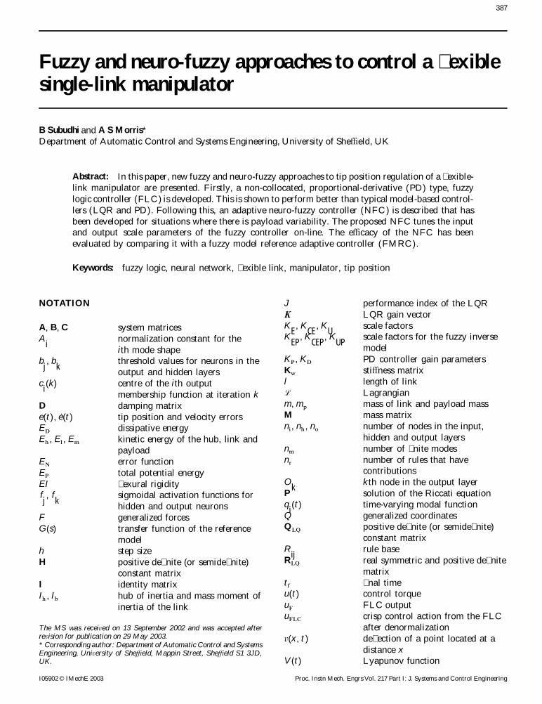
The knowledge base provides the membership functionsand the linguistic control rules The fuzzy inferenceengine performs fuzzy reasoning based on the linguisticcontrol rules using Zadehrsquos compositional rule of infer-ence [12] The defuzzi cation block generates a crispcontrol output u(t) by utilizing the centre of gravitymethod [12]
u(t)=aringnri=1
mi(u) u
iaringnri=1
mi(u)
(3)
where ui
is the centroid and mi(u) is the membership
function value of the fuzzy set for the consequent (con-trol action in this case) inferred at the ith quantizationlevel on the control space (UOD) n
r is the number ofFig 1 Structure of the PDndashFLCquantization intervals Just like input normalization theoutput (un) in the computational UOD (Un) is denor-
The PDndashFLC consists of a normalization unit malized by using the scale factor KU
to obtain the controlfuzzi cation interface knowledge base fuzzy inference action u(t) in the actual UOD (U )system defuzzi cation interface and a denormalization The rst priority is to tune the scaling factors (SFs)unit In this design the tip position error e(t) and veloc- because these are the global tuning parameters that a ectity error eb(t) as de ned below are chosen as the input the overall control performance In adjusting these con-variables to the FLC and the control torque u(t ) is sideration is given to rise time (tr) overshoot (OS) andconsidered as the output the steady state error When the response is far away
from the desired value the input SFs are adjusted toe(t)=yd(t) shy yt(t) (1)reduce the rise time and are later readjusted to prevent
eb(t)=ybd(t) shy yb
t(t) (2) overshoot as the response approaches the desired value
The output SF is tuned to limit the FLC output to awhere yt(t) and yb t(t) are the actual tip displacement andreasonable value and to reduce the steady state errorvelocity of the exible arm and yd(t ) and ybd(t) are the(ess) A basic manual tuning procedure that can be useddesired tip displacement and velocity respectively Thefor the FLC input and output SFs is given in Table 1input normalization block transforms the input variables
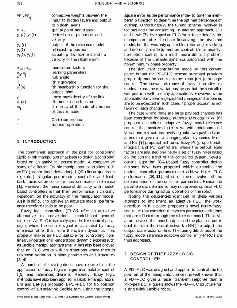
Selection of appropriate fuzzy control rules is essentialof the FLC (e and eb) on the actual universe of discoursefor obtaining e cient performance of the FLC Several(UOD) (E and CE ) to the normalized universe of dis-methods of deriving appropriate ifndashthen fuzzy rulescourse En and CEn (en and cen) in the range of (shy 10 tocould be used [8 12] but this paper uses an error10) using the input scale factors K
Eand K
CEfor compu-
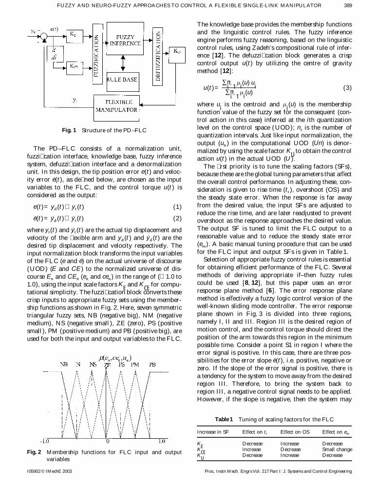
response plane method [6 ] The error response planetational simplicity The fuzzi cation block converts thesemethod is e ectively a fuzzy logic control version of thecrisp inputs to appropriate fuzzy sets using the member-well-known sliding mode controller The error responseship functions as shown in Fig 2 Here seven symmetricplane shown in Fig 3 is divided into three regionstriangular fuzzy sets NB (negative big) NM (negativenamely I II and III Region III is the desired region ofmedium) NS (negative small ) ZE (zero) PS (positivemotion control and the control torque should direct thesmall ) PM (positive medium) and PB (positive big) areposition of the arm towards this region in the minimumused for both the input and output variables to the FLCpossible time Consider a point S1 in region I where theerror signal is positive In this case there are three pos-sibilities for the error slope eb(t) ie positive negative orzero If the slope of the error signal is positive there isa tendency for the system to move away from the desiredregion III Therefore to bring the system back toregion III a negative control signal needs to be appliedHowever if the slope is negative then the system may
Table 1 Tuning of scaling factors for the FLC
Increase in SF E ect on tr E ect on OS E ect on ess
KE Decrease Increase DecreaseK
CEIncrease Decrease Small changeFig 2 Membership functions for FLC input and output K
UDecrease Increase Decrease
variables
I05902 copy IMechE 2003 Proc Instn Mech Engrs Vol 217 Part I J Systems and Control Engineering
390 B SUBUDHI AND A S MORRIS
Fig 3 Error response method for deriving fuzzy rules
have an inclination to produce overshoot from the to nd the fuzzy control vector asdesired region suggesting that a positive control torque U(u)= |
i=1n
E(ej)m CE(eb
k)mR
jk(e
j eb
k u
i)
should be applied Finally if the error slope is zero thisimplies that there may be a steady state error Hence in where n (n= jl ) is the number of rulesorder to bring the system back to region III a positivetorque should be applied so that the system has a positiveerror slope at the next iteration By doing so the negative 3 FUZZY MODEL REFERENCE ADAPTIVEcontrol signal is activated and drives the system to the CONTROLLERdesired region The rules pertaining to regions II and IIIcan be obtained using similar reasoning In this way 49
As discussed in the Introduction section 1 the fuzzyrules were constructed as shown in Table 2controllers discussed in section 2 will work satisfactorilyUsing the compositional rule of inference the fuzzyprovided that the manipulator system dynamics are rela-control istively undisturbed However when the dynamics of the
U=(EtimesCE ) J R (4) robot are varied by a large payload change the FLCparameters need re-tuning to maintain good control per-where R is the rule base times is the Cartesian product andformance An alternative to the tedium of parameterJ is the sup-min operation It may be noted here that there-tuning is to design an adaptive FLC where the on-lineantecedent indices j and k respectively for E(e
j) and
re-tuning algorithm for the FLC parameters is based onCE(ebk) in the rule base are used to access the correspond-
the reference model One such scheme is the FMRC [8 ]ing consequent U(ui) for the ith rule R
i(which is the
shown in Fig 4 which consists of four main blocks iesame as Rjk
) The control action U(ui) for the ith rule
the system to be controlled (FM) the conventional FLCcan be obtained usingto be tuned a reference model (REF MODEL) which
U(ui)=E(e
j)mCE(eb
k)m R
jk(e
j eb
k u
i) (5) carries the performance objective information and a
learning mechanism The FMRC only tunes the outputand a maximum operation is performed over all the rulesmembership functions and does not a ect the inputmembership functions The learning mechanism tunesthe rule base of the direct fuzzy controller so that the
Table 2 Fuzzy rule base for the PDndashFLC closed system behaves like the reference model Thelearning mechanism consists of two parts namely a fuzzyU E inverse model and a knowledge base modi er The fuzzy
CE inverse model maps er(t ) to changes in the system inputsNB NM NS ZE PS PM PB
c (t ) that are necessary to force er(
t ) to zero er(
t) isNB PS PS PS NB NM NM NB obtained by comparing the actual tip position withNM PM PS PS NM NS NM NB the output of the reference model ym(t) er(t)=NS PB PM PS NS NS NM NM
ym(t) shy yt(t) The knowledge base modi er adjusts theZE PM PS PS ZE NS NS NMPS PB PM PS PM NS NS NB rule base of the FLC to e ect the changes needed in thePM PB PM PS PM NS NS NM control torque K
EP K
CEPand K
UPare the scaling factors
PB PB PM PM PB NS NS NSof the fuzzy inverse model which are similar to the
I05902 copy IMechE 2003Proc Instn Mech Engrs Vol 217 Part I J Systems and Control Engineering
391FUZZY AND NEURO-FUZZY APPROACHES TO CONTROL A FLEXIBLE SINGLE-LINK MANIPULATOR
Fig 4 Fuzzy model reference adaptive controller
scaling parameters of the FLC (KE K
CEand K
U) as set do not have their output membership functions
modi eddescribed earlierThe knowledge base modi er changes the rule base of
the FLC so that the previously applied control action is4 NEURO-FUZZY CONTROLLERmodi ed by an amount c (k) where k is the iteration
number Consider the previously computed controlaction u(k shy 1) and assume that it contributed to the It is well known that although FLCs work well with
imprecise dynamics or even with no knowledge aboutpresent good or bad system performance ie such thatthe value of yt(k) does or does not match the model the system dynamics they do not have a learning capa-
bility of their own However a learning mechanism isoutput ym(k) Now with the error and change of error
as e(k shy 1) and ce(k shy 1) the rule base of the FLC can created if NNs which have good learning attributes arehybridized with fuzzy systems The resulting systemsbe modi ed to produce a desired outputare popularly known as fuzzy neural systems or neuro-
u(k shy 1)+c (k) (6)fuzzy systems Various neuro-fuzzy systems have beenreported that use NNs to modify FLC parameters suchLet c
i(k) be the centre of the ith output membership
function at iteration k For all rules in the active set as scaling factors membership functions and the rulebase [13ndash16 ] Neuro-fuzzy systems can usually be rep-modi cation of the output membership function centres
can be achieved using the following relation resented as multilayered feedforward networks such asANFIS [15] FuNe [17] and NEFCON [18] Sometimes
ci(k)=c
i(k shy 1)+c (k) (7)
a four-layer architecture is used [14] where the member-ship functions are represented in the neurons of theIt may be noted that the rules that are not in the active
I05902 copy IMechE 2003 Proc Instn Mech Engrs Vol 217 Part I J Systems and Control Engineering
392 B SUBUDHI AND A S MORRIS
second layer and the third layer is a rule layer followed manipulator The MLPNN can have many layers witha reasonable number of nodes in each oneby a fourth layer for the FLC output A neuro-fuzzy
system for on-line tuning of the output scale factors was A three-layer NN is employed for on-line tuning ofthe input scale factors (K
Eand K
CE) and the output scaleproposed by Lin et al [16 ] but this has no mechanism
for adjusting the input scaling factors In addition this factor (KU
) of the FLC where the NN inputs are selectedas e(t)=y
t(t) shy y
d(t) and eb(t)=ybt(
t) shy ybd(t) The sig-FLC was designed with quantized input and output vari-
ables which may not be a good choice for controlling nals to the input layer are not weighted and are thereforephysical systems like exible manipulators that have very given as net
i=x
i where x
irepresents the ith input to
complex dynamics the node of the input layer The output of the ith neuronIn contrast the work presented in this paper proposes in this layer is Q
i= f
i(net
i)=net
i For the hidden layer
a hybrid neuro-fuzzy controller that tunes both the input the signal input and the output of the jth neuron can beand output scale factors of the FLC by means of a three- expressed aslayered perceptron neural network Also continuousUODs for the FLC input and output variables are used
netj= aelig
ni
i(W
jiO
i)+b
j O
j= f
j(net
j)=
1
1+e Otilde netjin the FLC design instead of a discrete UOD The pro-posed scheme (Fig 5) incorporates FLC NN and PD (8)controller blocks The purpose of using the PD control-
where Wji
are the connection weights between the inputler is to enhance the rise time of the system output duringand the hidden layer b
jare the threshold values for thethe initial learning phase of the NN A multilayer per-
units in the hidden layer ni
is the number of nodesceptron neural network (MLPNN ) is used to build thehybrid neuro-fuzzy controller applied to the exible in the input layer and f
jis the sigmoidal activation
Fig 5 Hybrid neuro-fuzzy controller
I05902 copy IMechE 2003Proc Instn Mech Engrs Vol 217 Part I J Systems and Control Engineering
393FUZZY AND NEURO-FUZZY APPROACHES TO CONTROL A FLEXIBLE SINGLE-LINK MANIPULATOR
function Finally the signal and activation for the output mated aslayer of the NN are given by
netk= aelig
nh
j(W
kjO
j)+b
k O
k= f
k(net
k) (9) qyt
quFLC=GM
qytquFLC
gt0
shy Mqy
tqu
FLClt0where W
kjare the connection weights between the output
and the hidden layer bk
are the threshold values for theunits in the output layer n
h is the number nodes in the where M is the known bound of the manipulator systemhidden layer and f
kis the sigmoidal activation function which can be considered as a nite slew rate Therefore
equation (14) can be modi ed to
dk=er(plusmnM )uF
quFLCqnet
k=er(plusmnM )uF f ecirc (net
k) (15)41 Training of the NN
The on-line training algorithm for the NN can be derivedError for k=2 and 3 (input scale factors)in terms of the error function E
N as
EN
=12e2r
=12(y
mshy y
t)2 (10)d
k=shy
qENqer
qerqyt
qytquFLC
quFLCqO
k
qOk
netk=er A qyt
qOkB qO
kqnet
kThen the learning algorithm is as follows (16)
To simplify computation qytqO
kcan be approximated411 Output layer
by a bound N similar to the one used for approximatingThe weights are updated using the steepest descent qy
tquFLC Therefore equation (16) becomes
methodd
k=er(plusmnN ) f ecirc (net
k) (17)
centWkj
=shy gk
qENqW
kj=shy g
kqENqnet
k
qnetk
qWkj
=gkd
kO
j(11)
412 Hidden layer
where the factor gk
is the learning parameter for the The error term to be propagated is given byconnection weights between the output and the hiddenlayers The weights of the output layer are updated
dj=shy
qENqnet
j=shy
qENqnet
k
qnetk
qOj
qOj
netj
(18)according to the back-propagation algorithm In orderto increase the learning rate without leading to oscil-
with weights updated according tolation in the output response momentum factors amoand amh are included in the adapting weights W
kjand
Wji
[19] centWji
=shy gj
qENqW
ji=shy g
jqENqnet
j
qnetj
qWji
=gjdjO
i(19)
Wkj
(t+1)=Wkj
(t)+centWkj
(t)+amocentW
kj(t ) (12)
where the factor gjis the learning parameter for adapting
The error term to be propagated is given by the connection weights between the hidden and the inputlayers The weights of the hidden layer are updatedaccording tod
k=shy
qENqnet
k=shy
qENqer
qerqyt
qytquFLC
quFLCqO
k
qOk
netk
(13)
Wji
(t+1)=Wji
(t)+centWji
(t)+amhWji
(t) (20)where uFLC=uFK
U=uFO
k uFLC is the crisp control
action from the FLC after denormalization uF is the The bias of each neuron in the hidden and outputFLC output and O
kis the kth node in the output layer layers is trained on-line using the same learning rate
The output layer consists of three nodes as shown in parametersFig 5 corresponding to the scale factors (K
E K
CE K
U)
The errors propagated to these nodes for k=1 2 3 areas follows
42 Stability of the NFCError for k=1 (output scale factor)
By choosing suitable values for the learning parametersof the connection weights between the hidden and input
dk=shy
qENqe
r
qerqy
t
qytqu
FLC
quFLCqO
k
qOk
netk
(14) layers (gj) and the output and hidden layers (g
k) the
convergence of the NFC is guaranteed This is shownas followsThe Jacobian of the system qy
tqu
FLC can be approxi-
I05902 copy IMechE 2003 Proc Instn Mech Engrs Vol 217 Part I J Systems and Control Engineering
394 B SUBUDHI AND A S MORRIS
Lemma 1 [14] the change in Lyapunov function is
If f (a)=a shy a2 then f (a) aring 025 Y amicro[0 1] centV=V(t+1) shy V(t)
2h=
e2r (t+1) shy e2r(t)
2h(24)
Theorem (convergence of NFC)
If gj
and gk
are chosen as where h denotes the step size The tracking error er(t+1)is
gk=
1
(LkjmaxuF)2
=16
Pkj
u2F) er(
t+1)=er(
t)+ Cqer(
t)
qWkDT
centWk
(25)and
where centWk
denotes the change in weights of the NNgj=
1
(LjimaxuF)2
=256
|Wkj
|2maxPjiu2F
between the hidden and the output layers Replacingthe Jacobian of the system by its sign function usingequation (12) givesthen the convergence of the NFC is guaranteed where
Lkj max and L
ji max are de ned asd e
r(t+1) d = d e
r(t)[1 shy g
ku2F
LTkj
Lkj
] dL
kjmax=maxt
d Lkj
(t) d aring d er(t) d d [1 shy gku2FLT
kjL
kj] d (26)
If gk
is chosen asand
Ljimax= max
td L
ji(t) d
gk=
1
(LkjmaxuF)2
=16
Pkj
u2Fwiththen the term d [1 shy g
ku2FLT
kjL
kj] d in equation (26) is less
than 1 Similarly Lji
(t) can be written asLkj
(t)=qO
kqW
kjL
ji(t)=
qOk
qWji
=qO
kqnet
k
qnetk
qOj
qOj
qnetj
qnetj
qWjiL
ji(t )=
qOk
qWji = f ecirc
k(net
k) aelig
jW
kjf ecircj
aeligi
Oi
(27)d middot d is the Euclidean norm in n and W
kjmax is de nedNow combining the bounds of f ecirc
k( middot) and f ecirc
j( middot) equationas
(27) can be written asWkj max
= maxt
d Wkj
(t) d
Lji
(t) aring1
16|W
kj|max |O
i|max=
d Wkj
d d Oid
16(28)P
knis the number of weights between the output and
hidden layer in the NN and Pjn
is the number of weightsHencebetween the hidden and output layers
Proof For a sigmoidal activation function d Lj(t) d aring aelig
i
n=1SP
ji4
f ecirck(net
k)= f
k(net
k)[1 shy f
k(net
k)]
The change in error can also be written in a similarUsing Lemma 1 fashion to equation (25) in terms of W
jand weight
changes centWj(a vector of weight changes from the hiddenf ecirc
k(net
k)= f
k(net
k)[1 shy f
k(net
k)]
layer to the input layer)aring 025 for f
k(net
k)micro[0 1] Because the Jacobian of the system is replaced by its
sign function equation (19) can be used to giveLkj
(t) can be written as
d er(
t+1) d = d er(
t)[1 shy gju2F
LTji
Lji
] dL
kj(t)=
qOk
qWkj
=qO
kqnet
k
qnetk
qWkj
= f ecirck(net
k)O
jaring 025O
j aring d er(t) d d [1 shy gju2FLT
jiL
ji] d (29)
(21)From equation (29) it can be seen that if g
jis chosen
Therefore from equation (21) as
d Lk(t) d aring aelig
j
n=1
atilde Pkn
4(22) g
j=
1
(LjimaxuF)2
=256
|Wkj
|2maxPji
u2Fthen d [1 shy g
ju2FLT
jiL
ji] d lt1 Thus the Lyapunov stab-Let V(t) be a Lyapunov function chosen as
ility (Vgt0 and centVlt0) is guaranteed The trackingV(t)=12e2r (t) (23)
error er(t) 0 as t Therefore the theorem hasbeen provedwhere e
r(t) is the tracking error From equation (23)
I05902 copy IMechE 2003Proc Instn Mech Engrs Vol 217 Part I J Systems and Control Engineering
395FUZZY AND NEURO-FUZZY APPROACHES TO CONTROL A FLEXIBLE SINGLE-LINK MANIPULATOR
5 RESULTS AND DISCUSSION more overshoot compared with the FLC and LQR Thetip position trajectory with the PD has a fast rise timebut overshoots more than the FLC The tip position51 Performance of the FLC compared with the PDwith the LQR has a delayed rise time and higher over-and LQRshoot compared with the FLC Control pro les of the
In order to demonstrate the superior performance of the controllers are shown in Fig 9 Initially the controlFLC an analytic system model was developed and two torque rises to a maximum of 25 235 and 23 N m withalternative model-based controllers based on the PD and the PD LQR and FLC respectively and in all casesLQR approaches were designed It has already been the control torque eventually becomes zero when thenoted that the performance of model-based controllers desired tip displacement is achieved and the vibration isis crucially dependent on the accuracy of the dynamic completely damped outsystem model Many previously published models haveinaccuracies but recent work [20 ] has described amodel of improved accuracy this forms the basis of the 52 Performance of the NFC compared with the FMRmodel used for this current work Two model-based con-trollers were developed rstly a proportional-derivative Next the e ectiveness of the proposed NFC is compared
with the FMRC For the FMRC and the proposed NFCcontroller (PDC) and secondly a linear quadraticregulator (LQR) the reference model is taken from reference [8 ] G(s)=
Kr(s+ar) where ar=30 and Kr=30 The model isFigures 6 to 9 compare the results obtained with the
PD FLC and LQR for tip position control when the discretized at the same sampling time of 0001 s Thestructure of the NN for the NFC was chosen with two exible manipulator was commanded to move from an
initial position of 0 rad to a target tip position of 05 rad input nodes 20 hidden nodes and two output nodes Thetwo inputs to the NN as discussed in section 4 are thewith the parameters of the FLC set at K
E=04 K
CE=
015 KU
=50 The rst mode trajectories with the PD tip position error e(t) and the tip velocity error eb(t) Ithas been con rmed through di erent trial runs of theFLC and LQR are compared in Fig 6 The rst mode
of vibration is damped faster and has a smaller ampli- NFC that choosing 20 hidden neurons gives the bestresults The initial weights were set with small randomtude with the FLC compared to the other two control-
lers (Although not shown to save space the FLC also values in the range of plusmn01 The momentum factors amoand amh were chosen as 01 and 015 respectivelyhas the smallest second modal vibration and damps it
in the least time) From the tip de ection trajectories Figure 10 gives the tip position trajectories obtainedwith the NFC and FMRC showing that the NFC per-shown in Fig 7 it can be seen that de ection is less with
the LQR than for the PD and FLC However the FLC forms better than the FMRC Figure 11 compares the rst mode trajectories and shows that the amplitude ofdamps out the de ection faster compared to the other
controllers Figure 8 shows the tip position trajectories this modal vibration is less for the NFC than the FMRC(Although not shown to save space the second modefor the PD FLC and LQR The PD controller gives
Fig 6 Comparison of rst mode trajectories with the PD LQR and FLC
I05902 copy IMechE 2003 Proc Instn Mech Engrs Vol 217 Part I J Systems and Control Engineering
396 B SUBUDHI AND A S MORRIS
Fig 7 Comparison of tip de ection trajectories with the PD LQR and FLC
Fig 8 Tip position trajectories with the PD LQR and FLC
of vibration also has a smaller amplitude with the NFC) 6 CONCLUSIONSFigure 12 compares the tip vibrations and it is obviousthat the NFC damps out the end vibration more e ec- As explained in section 1 model-based controllers such
as the PD and LQR generally perform poorly owing totively The control signals generated are compared inFig 13 Initial torques of 102 and 98 N m respectively inaccuracies in the models on which they depend Fuzzy
logic controllers because they do not require a prioriwere produced with the NFC and FMRC at maximumde ection but then the control torques decay to zero as development of an analytic system model can poten-
tially perform much better Previous applications of thethe tip position error reduces to zero
I05902 copy IMechE 2003Proc Instn Mech Engrs Vol 217 Part I J Systems and Control Engineering
397FUZZY AND NEURO-FUZZY APPROACHES TO CONTROL A FLEXIBLE SINGLE-LINK MANIPULATOR
Fig 9 Control torque requirements with the PD LQR and FLC
Fig 10 Comparison of tip regulation performance with the NFC and FMRC
FLC to exible manipulators have been de cient in vari- adaptive controller (FMRC ) that tunes the rule baseof the FLC and the membership functions on-lineous respects as discussed and the contribution made by
this paper has been in the development of an FLC that However this approach is not always successful becauseit sometimes becomes di cult for the FMRC to tuneprovides good control of tip motion in the manipulator
Simulation results have con rmed the superior perform- six scale parameters (KE E
CEand K
Ufor the FLC and
KEP
KCEP
and KUP
for the fuzzy inverse model ) Toance compared with model-based control schemesIn the case where there is signi cant payload variation avoid this problem a neuro-fuzzy controller has been
described that uses an NN to tune the input and thethe necessary re-tuning of the FLC parameters is tediousPrevious work has proposed a fuzzy model reference output scale factor parameters of the FLC on-line The
I05902 copy IMechE 2003 Proc Instn Mech Engrs Vol 217 Part I J Systems and Control Engineering
398 B SUBUDHI AND A S MORRIS
Fig 11 First mode suppression performance with the NFC and FMRC
Fig 12 Tip de ection curves with the NFC and FMRC
results presented have compared the performance of this ive scale factors tuning algorithm The proposed hybridneuro-fuzzy controller provides a fast response whenwith that of an alternative fuzzy adaptive controller
reported previously [8 ] This comparison has shown the applied on-line to the exible manipulator system byutilizing the good transient state performance of the PDsuperior performance of the neuro-fuzzy adaptive con-
troller developed A particular advantage of the new controller As the proposed controller tunes the param-eters on-line unlike the o -line GA-based optimizedcontroller is that it does not require knowledge of a
mathematical model It has also been shown that the FLC it is more likely to be more suitable for real-timeapplicationsperformance of the FLC can be enhanced by the adapt-
I05902 copy IMechE 2003Proc Instn Mech Engrs Vol 217 Part I J Systems and Control Engineering
399FUZZY AND NEURO-FUZZY APPROACHES TO CONTROL A FLEXIBLE SINGLE-LINK MANIPULATOR
Fig 13 Control torque pro les with the NFC and FMRC
10 Karr C L and Gentry E J Fuzzy control of PH usingREFERENCESgenetic algorithms IEEE Trans Fuzzy Systems 19931(1) 46ndash531 Aoustin Y Chevallereau C Glumineeau A and Moog
11 Zhou Y S and Lai L-Y Optimal design for fuzzy control-C H Experimental results for the end-e ector control oflers by the genetic algorithms IEEE Trans Industry Applica single exible robot arm IEEE Trans Control Systems2000 36(1) 93ndash97Technol 1994 2(4) 371ndash381
12 Kotnik P T Yurkovitch S and Ozguner U Acceleration2 Mamdani E H and Assilian S An experiment in linguisticfeedback control of a exible manipulator J Roboticnetwork with a fuzzy logic controller Int J ManndashMachineSystems 1988 5(3) 181ndash196Studies 1975 7(1) 1ndash13
13 Chen M and Linkens D A A hybrid neuro-fuzzy control-3 Sayyarrodsari B and Homaifar A The role of hierarchyler Fuzzy Sets and Systems 1998 99 27ndash36in the design of fuzzy logic controllers IEEE Trans
14 Halgamauge S K and Glesner M Neural networks forSystems Man and Cybernetics Part B Cybernetics 1997designing fuzzy systems for real-world applications Fuzzy27(1) 108ndash118Sets and Systems 1994 65 1ndash24 Suh I H Eom K S Yeo H J and Oh S R Fuzzy
15 Jang J-S R ANFIS adaptive network based fuzzy infer-adaptive control of industrial robot manipulators withence systems IEEE Trans Systems Man and Cyberneticsposition servos Mechatronics 1995 5(8) 899ndash9181993 23(3) 665ndash6855 Soo Y Y and Chung J M A robust fuzzy logic controller
16 Lin F J Jong W R and Wang S L A fuzzy neuralfor manipulators with uncertainties IEEE Trans Systemsnetwork controller for parallel-resonant ultrasonic motorMan and Cybernetics Part B Cybernetics 1997 27(4)drive IEEE Trans Ind Electronics 1998 45(6) 929ndash937707ndash713
17 Nauck D Klawonn F and Kruse R Foundationsof Neuro-6 Lin Y J and Lee T S An investigation of fuzzy logicFuzzy Systems 1996 (John Wiley Chichester)control of exible robots Robotica1993 11(3) 363ndash371
18 Lin F-J and Wai R-J A hybrid computed torque con-7 Liu K and Lewis F L Hybrid feedback linearizationtroller using fuzzy neural network for motor-quick-returnfuzzy logic control of a exible link manipulator J Intellservo mechanism IEEE Trans Mechatronics 2001 6(1)Fuzzy Systems 1994 2 325ndash33685ndash898 Moudgal V G Passino K M and Yurkovitch S Rule-
19 Omatu S Khalid M and Yusof R Neuro-Control and Itsbased control for exible-link robot IEEE Trans ControlApplications 1996 (Springer London)Systems Technol 1994 12 393ndash405
20 Morris A S and Madani A Static and dynamic modelling9 Mudi R K and Pal N R A robust self-tuning schemeof a two- exible-link manipulator Robotica 1996 14for PI and PD type fuzzy controllers IEEE Trans Fuzzy289ndash300Systems 1999 7(1) 3ndash16
I05902 copy IMechE 2003 Proc Instn Mech Engrs Vol 217 Part I J Systems and Control Engineering
388 B SUBUDHI AND A S MORRIS
Wji
Wkj
connective weights between the square error as the performance index to tune the mem-bership function to determine the optimal percentage ofinput to hidden layers and output
to hidden layers overlap Unfortunately the tuning scheme involved istedious and time consuming In another approach Liux xs spatial point and states
yd(t) yb
d(t) desired tip displacement and and Lewis [7 ] developed an FLC for a single-link exiblemanipulator after feedback-linearizing the dynamicvelocity
ym(t) output of the reference model model but this was only applied for rotor-angle trackingand did not provide tip-motion control Unfortunatelyyr(t) re ected tip position
yt(t) yb t(t) actual tip displacement and tip tip-motion control is a much more di cult problembecause of the unstable dynamics associated with thevelocity of the exible armnon-minimum phase property
amo amh momentum factors The signi cant contribution made by this currentg
k g
jlearning parameters paper is that the PDndashFLC scheme presented provides
h hub angle proper tip-motion control rather than just joint-angleli
ith eigenvalue control The known tolerance of fuzzy controllers tom
i(u) ith membership function for the moderate parameter variations means that the controller
output label will perform well in many applications However somer linear mass density of the link applications involve large payload changes and problemsw
i(x) ith mode shape function are to be expected in such cases if proper account is not
vi
frequency of the natural vibration taken of such changesof the ith mode The case where there are large payload changes has
been considered by several authors Moudgal et al [8 ]times Cartesian productproposed an indirect adaptive fuzzy model referenceJ sup-min operationcontrol that achieves faster slews with minimum endvibrations in situations involving unknown payload vari-ations that give rise to changing plant dynamics Mudi
1 INTRODUCTION and Pal [9 ] proposed self-tuned fuzzy PI (proportional-integral ) and PD controllers where the output scalefactors are adjusted on-line by a set of fuzzy rules basedThe commonest approach in the past for controlling
exible-link manipulators has been to design a controller on the current trend of the controlled system Severalgenetic algorithm (GA)-based fuzzy controller designbased on an analytical system model A comparative
study of di erent exible manipulator controllers such methods have been proposed which determine theoptimal controller parameters to achieve better FLCas PD (proportional-derivative) LQR ( linear quadratic
regulator) singular perturbation controller and feed- performance [10 11] Most of these involve o -linedetermination of the controller parameters Hence theback linearization controller has been made in reference
[1 ] However the major cause of di culty with model- parameters so determined may not provide optimal FLCperformance during actual operation of the robotbased controllers is that their performance is crucially
dependent on the accuracy of the manipulator model Noting the de ciencies identi ed in these variousattempts to implement an adaptive FLC the workAs it is di cult to achieve an accurate model perform-
ance therefore tends to be poor described in this paper proposes a novel neuro-fuzzycontroller that considers the system parameter variationsFuzzy logic controllers (FLCs) o er an attractive
alternative to conventional model-based control that are re ected through the reference model The devi-ation between the model output and the plant output isschemes An FLC is basically a model-free control para-
digm where the control signal is calculated by fuzzy used to train the neural network (NN) to adjust theoutput scale factor on-line The tuning di culties of theinference rather than from the system dynamics This
property makes an FLC suitable for controlling non- fuzzy model reference adaptive controller (FMRC ) arethus addressedlinear uncertain or ill-understood dynamic systems such
as exible manipulator systems It has also been provedthat an FLC works well in situations where there is
2 DESIGN OF THE FUZZY LOGICunknown variation in plant parameters and structuresCONTROLLER[2ndash4 ]
A number of investigations have reported on theapplication of fuzzy logic in rigid manipulator control A PDndashFLC was designed and applied to control the tip
position of the manipulator since it is well known that([5 ] and references therein) Recently fuzzy logicmethods have also been applied in exible manipulators a PDndashFLC gives a faster transient response than a
PI-type FLC Figure 1 shows the PDndashFLC structure forLin and Lee [6 ] proposed a PDndashFLC for tip positioncontrol of a single-link exible arm using the integral a single-link exible robot
I05902 copy IMechE 2003Proc Instn Mech Engrs Vol 217 Part I J Systems and Control Engineering
389FUZZY AND NEURO-FUZZY APPROACHES TO CONTROL A FLEXIBLE SINGLE-LINK MANIPULATOR
The knowledge base provides the membership functionsand the linguistic control rules The fuzzy inferenceengine performs fuzzy reasoning based on the linguisticcontrol rules using Zadehrsquos compositional rule of infer-ence [12] The defuzzi cation block generates a crispcontrol output u(t) by utilizing the centre of gravitymethod [12]
u(t)=aringnri=1
mi(u) u
iaringnri=1
mi(u)
(3)
where ui
is the centroid and mi(u) is the membership
function value of the fuzzy set for the consequent (con-trol action in this case) inferred at the ith quantizationlevel on the control space (UOD) n
r is the number ofFig 1 Structure of the PDndashFLCquantization intervals Just like input normalization theoutput (un) in the computational UOD (Un) is denor-
The PDndashFLC consists of a normalization unit malized by using the scale factor KU
to obtain the controlfuzzi cation interface knowledge base fuzzy inference action u(t) in the actual UOD (U )system defuzzi cation interface and a denormalization The rst priority is to tune the scaling factors (SFs)unit In this design the tip position error e(t) and veloc- because these are the global tuning parameters that a ectity error eb(t) as de ned below are chosen as the input the overall control performance In adjusting these con-variables to the FLC and the control torque u(t ) is sideration is given to rise time (tr) overshoot (OS) andconsidered as the output the steady state error When the response is far away
from the desired value the input SFs are adjusted toe(t)=yd(t) shy yt(t) (1)reduce the rise time and are later readjusted to prevent
eb(t)=ybd(t) shy yb
t(t) (2) overshoot as the response approaches the desired value
The output SF is tuned to limit the FLC output to awhere yt(t) and yb t(t) are the actual tip displacement andreasonable value and to reduce the steady state errorvelocity of the exible arm and yd(t ) and ybd(t) are the(ess) A basic manual tuning procedure that can be useddesired tip displacement and velocity respectively Thefor the FLC input and output SFs is given in Table 1input normalization block transforms the input variables
Selection of appropriate fuzzy control rules is essentialof the FLC (e and eb) on the actual universe of discoursefor obtaining e cient performance of the FLC Several(UOD) (E and CE ) to the normalized universe of dis-methods of deriving appropriate ifndashthen fuzzy rulescourse En and CEn (en and cen) in the range of (shy 10 tocould be used [8 12] but this paper uses an error10) using the input scale factors K
Eand K
CEfor compu-
response plane method [6 ] The error response planetational simplicity The fuzzi cation block converts thesemethod is e ectively a fuzzy logic control version of thecrisp inputs to appropriate fuzzy sets using the member-well-known sliding mode controller The error responseship functions as shown in Fig 2 Here seven symmetricplane shown in Fig 3 is divided into three regionstriangular fuzzy sets NB (negative big) NM (negativenamely I II and III Region III is the desired region ofmedium) NS (negative small ) ZE (zero) PS (positivemotion control and the control torque should direct thesmall ) PM (positive medium) and PB (positive big) areposition of the arm towards this region in the minimumused for both the input and output variables to the FLCpossible time Consider a point S1 in region I where theerror signal is positive In this case there are three pos-sibilities for the error slope eb(t) ie positive negative orzero If the slope of the error signal is positive there isa tendency for the system to move away from the desiredregion III Therefore to bring the system back toregion III a negative control signal needs to be appliedHowever if the slope is negative then the system may
Table 1 Tuning of scaling factors for the FLC
Increase in SF E ect on tr E ect on OS E ect on ess
KE Decrease Increase DecreaseK
CEIncrease Decrease Small changeFig 2 Membership functions for FLC input and output K
UDecrease Increase Decrease
variables
I05902 copy IMechE 2003 Proc Instn Mech Engrs Vol 217 Part I J Systems and Control Engineering
390 B SUBUDHI AND A S MORRIS
Fig 3 Error response method for deriving fuzzy rules
have an inclination to produce overshoot from the to nd the fuzzy control vector asdesired region suggesting that a positive control torque U(u)= |
i=1n
E(ej)m CE(eb
k)mR
jk(e
j eb
k u
i)
should be applied Finally if the error slope is zero thisimplies that there may be a steady state error Hence in where n (n= jl ) is the number of rulesorder to bring the system back to region III a positivetorque should be applied so that the system has a positiveerror slope at the next iteration By doing so the negative 3 FUZZY MODEL REFERENCE ADAPTIVEcontrol signal is activated and drives the system to the CONTROLLERdesired region The rules pertaining to regions II and IIIcan be obtained using similar reasoning In this way 49
As discussed in the Introduction section 1 the fuzzyrules were constructed as shown in Table 2controllers discussed in section 2 will work satisfactorilyUsing the compositional rule of inference the fuzzyprovided that the manipulator system dynamics are rela-control istively undisturbed However when the dynamics of the
U=(EtimesCE ) J R (4) robot are varied by a large payload change the FLCparameters need re-tuning to maintain good control per-where R is the rule base times is the Cartesian product andformance An alternative to the tedium of parameterJ is the sup-min operation It may be noted here that there-tuning is to design an adaptive FLC where the on-lineantecedent indices j and k respectively for E(e
j) and
re-tuning algorithm for the FLC parameters is based onCE(ebk) in the rule base are used to access the correspond-
the reference model One such scheme is the FMRC [8 ]ing consequent U(ui) for the ith rule R
i(which is the
shown in Fig 4 which consists of four main blocks iesame as Rjk
) The control action U(ui) for the ith rule
the system to be controlled (FM) the conventional FLCcan be obtained usingto be tuned a reference model (REF MODEL) which
U(ui)=E(e
j)mCE(eb
k)m R
jk(e
j eb
k u
i) (5) carries the performance objective information and a
learning mechanism The FMRC only tunes the outputand a maximum operation is performed over all the rulesmembership functions and does not a ect the inputmembership functions The learning mechanism tunesthe rule base of the direct fuzzy controller so that the
Table 2 Fuzzy rule base for the PDndashFLC closed system behaves like the reference model Thelearning mechanism consists of two parts namely a fuzzyU E inverse model and a knowledge base modi er The fuzzy
CE inverse model maps er(t ) to changes in the system inputsNB NM NS ZE PS PM PB
c (t ) that are necessary to force er(
t ) to zero er(
t) isNB PS PS PS NB NM NM NB obtained by comparing the actual tip position withNM PM PS PS NM NS NM NB the output of the reference model ym(t) er(t)=NS PB PM PS NS NS NM NM
ym(t) shy yt(t) The knowledge base modi er adjusts theZE PM PS PS ZE NS NS NMPS PB PM PS PM NS NS NB rule base of the FLC to e ect the changes needed in thePM PB PM PS PM NS NS NM control torque K
EP K
CEPand K
UPare the scaling factors
PB PB PM PM PB NS NS NSof the fuzzy inverse model which are similar to the
I05902 copy IMechE 2003Proc Instn Mech Engrs Vol 217 Part I J Systems and Control Engineering
391FUZZY AND NEURO-FUZZY APPROACHES TO CONTROL A FLEXIBLE SINGLE-LINK MANIPULATOR
Fig 4 Fuzzy model reference adaptive controller
scaling parameters of the FLC (KE K
CEand K
U) as set do not have their output membership functions
modi eddescribed earlierThe knowledge base modi er changes the rule base of
the FLC so that the previously applied control action is4 NEURO-FUZZY CONTROLLERmodi ed by an amount c (k) where k is the iteration
number Consider the previously computed controlaction u(k shy 1) and assume that it contributed to the It is well known that although FLCs work well with
imprecise dynamics or even with no knowledge aboutpresent good or bad system performance ie such thatthe value of yt(k) does or does not match the model the system dynamics they do not have a learning capa-
bility of their own However a learning mechanism isoutput ym(k) Now with the error and change of error
as e(k shy 1) and ce(k shy 1) the rule base of the FLC can created if NNs which have good learning attributes arehybridized with fuzzy systems The resulting systemsbe modi ed to produce a desired outputare popularly known as fuzzy neural systems or neuro-
u(k shy 1)+c (k) (6)fuzzy systems Various neuro-fuzzy systems have beenreported that use NNs to modify FLC parameters suchLet c
i(k) be the centre of the ith output membership
function at iteration k For all rules in the active set as scaling factors membership functions and the rulebase [13ndash16 ] Neuro-fuzzy systems can usually be rep-modi cation of the output membership function centres
can be achieved using the following relation resented as multilayered feedforward networks such asANFIS [15] FuNe [17] and NEFCON [18] Sometimes
ci(k)=c
i(k shy 1)+c (k) (7)
a four-layer architecture is used [14] where the member-ship functions are represented in the neurons of theIt may be noted that the rules that are not in the active
I05902 copy IMechE 2003 Proc Instn Mech Engrs Vol 217 Part I J Systems and Control Engineering
392 B SUBUDHI AND A S MORRIS
second layer and the third layer is a rule layer followed manipulator The MLPNN can have many layers witha reasonable number of nodes in each oneby a fourth layer for the FLC output A neuro-fuzzy
system for on-line tuning of the output scale factors was A three-layer NN is employed for on-line tuning ofthe input scale factors (K
Eand K
CE) and the output scaleproposed by Lin et al [16 ] but this has no mechanism
for adjusting the input scaling factors In addition this factor (KU
) of the FLC where the NN inputs are selectedas e(t)=y
t(t) shy y
d(t) and eb(t)=ybt(
t) shy ybd(t) The sig-FLC was designed with quantized input and output vari-
ables which may not be a good choice for controlling nals to the input layer are not weighted and are thereforephysical systems like exible manipulators that have very given as net
i=x
i where x
irepresents the ith input to
complex dynamics the node of the input layer The output of the ith neuronIn contrast the work presented in this paper proposes in this layer is Q
i= f
i(net
i)=net
i For the hidden layer
a hybrid neuro-fuzzy controller that tunes both the input the signal input and the output of the jth neuron can beand output scale factors of the FLC by means of a three- expressed aslayered perceptron neural network Also continuousUODs for the FLC input and output variables are used
netj= aelig
ni
i(W
jiO
i)+b
j O
j= f
j(net
j)=
1
1+e Otilde netjin the FLC design instead of a discrete UOD The pro-posed scheme (Fig 5) incorporates FLC NN and PD (8)controller blocks The purpose of using the PD control-
where Wji
are the connection weights between the inputler is to enhance the rise time of the system output duringand the hidden layer b
jare the threshold values for thethe initial learning phase of the NN A multilayer per-
units in the hidden layer ni
is the number of nodesceptron neural network (MLPNN ) is used to build thehybrid neuro-fuzzy controller applied to the exible in the input layer and f
jis the sigmoidal activation
Fig 5 Hybrid neuro-fuzzy controller
I05902 copy IMechE 2003Proc Instn Mech Engrs Vol 217 Part I J Systems and Control Engineering
393FUZZY AND NEURO-FUZZY APPROACHES TO CONTROL A FLEXIBLE SINGLE-LINK MANIPULATOR
function Finally the signal and activation for the output mated aslayer of the NN are given by
netk= aelig
nh
j(W
kjO
j)+b
k O
k= f
k(net
k) (9) qyt
quFLC=GM
qytquFLC
gt0
shy Mqy
tqu
FLClt0where W
kjare the connection weights between the output
and the hidden layer bk
are the threshold values for theunits in the output layer n
h is the number nodes in the where M is the known bound of the manipulator systemhidden layer and f
kis the sigmoidal activation function which can be considered as a nite slew rate Therefore
equation (14) can be modi ed to
dk=er(plusmnM )uF
quFLCqnet
k=er(plusmnM )uF f ecirc (net
k) (15)41 Training of the NN
The on-line training algorithm for the NN can be derivedError for k=2 and 3 (input scale factors)in terms of the error function E
N as
EN
=12e2r
=12(y
mshy y
t)2 (10)d
k=shy
qENqer
qerqyt
qytquFLC
quFLCqO
k
qOk
netk=er A qyt
qOkB qO
kqnet
kThen the learning algorithm is as follows (16)
To simplify computation qytqO
kcan be approximated411 Output layer
by a bound N similar to the one used for approximatingThe weights are updated using the steepest descent qy
tquFLC Therefore equation (16) becomes
methodd
k=er(plusmnN ) f ecirc (net
k) (17)
centWkj
=shy gk
qENqW
kj=shy g
kqENqnet
k
qnetk
qWkj
=gkd
kO
j(11)
412 Hidden layer
where the factor gk
is the learning parameter for the The error term to be propagated is given byconnection weights between the output and the hiddenlayers The weights of the output layer are updated
dj=shy
qENqnet
j=shy
qENqnet
k
qnetk
qOj
qOj
netj
(18)according to the back-propagation algorithm In orderto increase the learning rate without leading to oscil-
with weights updated according tolation in the output response momentum factors amoand amh are included in the adapting weights W
kjand
Wji
[19] centWji
=shy gj
qENqW
ji=shy g
jqENqnet
j
qnetj
qWji
=gjdjO
i(19)
Wkj
(t+1)=Wkj
(t)+centWkj
(t)+amocentW
kj(t ) (12)
where the factor gjis the learning parameter for adapting
The error term to be propagated is given by the connection weights between the hidden and the inputlayers The weights of the hidden layer are updatedaccording tod
k=shy
qENqnet
k=shy
qENqer
qerqyt
qytquFLC
quFLCqO
k
qOk
netk
(13)
Wji
(t+1)=Wji
(t)+centWji
(t)+amhWji
(t) (20)where uFLC=uFK
U=uFO
k uFLC is the crisp control
action from the FLC after denormalization uF is the The bias of each neuron in the hidden and outputFLC output and O
kis the kth node in the output layer layers is trained on-line using the same learning rate
The output layer consists of three nodes as shown in parametersFig 5 corresponding to the scale factors (K
E K
CE K
U)
The errors propagated to these nodes for k=1 2 3 areas follows
42 Stability of the NFCError for k=1 (output scale factor)
By choosing suitable values for the learning parametersof the connection weights between the hidden and input
dk=shy
qENqe
r
qerqy
t
qytqu
FLC
quFLCqO
k
qOk
netk
(14) layers (gj) and the output and hidden layers (g
k) the
convergence of the NFC is guaranteed This is shownas followsThe Jacobian of the system qy
tqu
FLC can be approxi-
I05902 copy IMechE 2003 Proc Instn Mech Engrs Vol 217 Part I J Systems and Control Engineering
394 B SUBUDHI AND A S MORRIS
Lemma 1 [14] the change in Lyapunov function is
If f (a)=a shy a2 then f (a) aring 025 Y amicro[0 1] centV=V(t+1) shy V(t)
2h=
e2r (t+1) shy e2r(t)
2h(24)
Theorem (convergence of NFC)
If gj
and gk
are chosen as where h denotes the step size The tracking error er(t+1)is
gk=
1
(LkjmaxuF)2
=16
Pkj
u2F) er(
t+1)=er(
t)+ Cqer(
t)
qWkDT
centWk
(25)and
where centWk
denotes the change in weights of the NNgj=
1
(LjimaxuF)2
=256
|Wkj
|2maxPjiu2F
between the hidden and the output layers Replacingthe Jacobian of the system by its sign function usingequation (12) givesthen the convergence of the NFC is guaranteed where
Lkj max and L
ji max are de ned asd e
r(t+1) d = d e
r(t)[1 shy g
ku2F
LTkj
Lkj
] dL
kjmax=maxt
d Lkj
(t) d aring d er(t) d d [1 shy gku2FLT
kjL
kj] d (26)
If gk
is chosen asand
Ljimax= max
td L
ji(t) d
gk=
1
(LkjmaxuF)2
=16
Pkj
u2Fwiththen the term d [1 shy g
ku2FLT
kjL
kj] d in equation (26) is less
than 1 Similarly Lji
(t) can be written asLkj
(t)=qO
kqW
kjL
ji(t)=
qOk
qWji
=qO
kqnet
k
qnetk
qOj
qOj
qnetj
qnetj
qWjiL
ji(t )=
qOk
qWji = f ecirc
k(net
k) aelig
jW
kjf ecircj
aeligi
Oi
(27)d middot d is the Euclidean norm in n and W
kjmax is de nedNow combining the bounds of f ecirc
k( middot) and f ecirc
j( middot) equationas
(27) can be written asWkj max
= maxt
d Wkj
(t) d
Lji
(t) aring1
16|W
kj|max |O
i|max=
d Wkj
d d Oid
16(28)P
knis the number of weights between the output and
hidden layer in the NN and Pjn
is the number of weightsHencebetween the hidden and output layers
Proof For a sigmoidal activation function d Lj(t) d aring aelig
i
n=1SP
ji4
f ecirck(net
k)= f
k(net
k)[1 shy f
k(net
k)]
The change in error can also be written in a similarUsing Lemma 1 fashion to equation (25) in terms of W
jand weight
changes centWj(a vector of weight changes from the hiddenf ecirc
k(net
k)= f
k(net
k)[1 shy f
k(net
k)]
layer to the input layer)aring 025 for f
k(net
k)micro[0 1] Because the Jacobian of the system is replaced by its
sign function equation (19) can be used to giveLkj
(t) can be written as
d er(
t+1) d = d er(
t)[1 shy gju2F
LTji
Lji
] dL
kj(t)=
qOk
qWkj
=qO
kqnet
k
qnetk
qWkj
= f ecirck(net
k)O
jaring 025O
j aring d er(t) d d [1 shy gju2FLT
jiL
ji] d (29)
(21)From equation (29) it can be seen that if g
jis chosen
Therefore from equation (21) as
d Lk(t) d aring aelig
j
n=1
atilde Pkn
4(22) g
j=
1
(LjimaxuF)2
=256
|Wkj
|2maxPji
u2Fthen d [1 shy g
ju2FLT
jiL
ji] d lt1 Thus the Lyapunov stab-Let V(t) be a Lyapunov function chosen as
ility (Vgt0 and centVlt0) is guaranteed The trackingV(t)=12e2r (t) (23)
error er(t) 0 as t Therefore the theorem hasbeen provedwhere e
r(t) is the tracking error From equation (23)
I05902 copy IMechE 2003Proc Instn Mech Engrs Vol 217 Part I J Systems and Control Engineering
395FUZZY AND NEURO-FUZZY APPROACHES TO CONTROL A FLEXIBLE SINGLE-LINK MANIPULATOR
5 RESULTS AND DISCUSSION more overshoot compared with the FLC and LQR Thetip position trajectory with the PD has a fast rise timebut overshoots more than the FLC The tip position51 Performance of the FLC compared with the PDwith the LQR has a delayed rise time and higher over-and LQRshoot compared with the FLC Control pro les of the
In order to demonstrate the superior performance of the controllers are shown in Fig 9 Initially the controlFLC an analytic system model was developed and two torque rises to a maximum of 25 235 and 23 N m withalternative model-based controllers based on the PD and the PD LQR and FLC respectively and in all casesLQR approaches were designed It has already been the control torque eventually becomes zero when thenoted that the performance of model-based controllers desired tip displacement is achieved and the vibration isis crucially dependent on the accuracy of the dynamic completely damped outsystem model Many previously published models haveinaccuracies but recent work [20 ] has described amodel of improved accuracy this forms the basis of the 52 Performance of the NFC compared with the FMRmodel used for this current work Two model-based con-trollers were developed rstly a proportional-derivative Next the e ectiveness of the proposed NFC is compared
with the FMRC For the FMRC and the proposed NFCcontroller (PDC) and secondly a linear quadraticregulator (LQR) the reference model is taken from reference [8 ] G(s)=
Kr(s+ar) where ar=30 and Kr=30 The model isFigures 6 to 9 compare the results obtained with the
PD FLC and LQR for tip position control when the discretized at the same sampling time of 0001 s Thestructure of the NN for the NFC was chosen with two exible manipulator was commanded to move from an
initial position of 0 rad to a target tip position of 05 rad input nodes 20 hidden nodes and two output nodes Thetwo inputs to the NN as discussed in section 4 are thewith the parameters of the FLC set at K
E=04 K
CE=
015 KU
=50 The rst mode trajectories with the PD tip position error e(t) and the tip velocity error eb(t) Ithas been con rmed through di erent trial runs of theFLC and LQR are compared in Fig 6 The rst mode
of vibration is damped faster and has a smaller ampli- NFC that choosing 20 hidden neurons gives the bestresults The initial weights were set with small randomtude with the FLC compared to the other two control-
lers (Although not shown to save space the FLC also values in the range of plusmn01 The momentum factors amoand amh were chosen as 01 and 015 respectivelyhas the smallest second modal vibration and damps it
in the least time) From the tip de ection trajectories Figure 10 gives the tip position trajectories obtainedwith the NFC and FMRC showing that the NFC per-shown in Fig 7 it can be seen that de ection is less with
the LQR than for the PD and FLC However the FLC forms better than the FMRC Figure 11 compares the rst mode trajectories and shows that the amplitude ofdamps out the de ection faster compared to the other
controllers Figure 8 shows the tip position trajectories this modal vibration is less for the NFC than the FMRC(Although not shown to save space the second modefor the PD FLC and LQR The PD controller gives
Fig 6 Comparison of rst mode trajectories with the PD LQR and FLC
I05902 copy IMechE 2003 Proc Instn Mech Engrs Vol 217 Part I J Systems and Control Engineering
396 B SUBUDHI AND A S MORRIS
Fig 7 Comparison of tip de ection trajectories with the PD LQR and FLC
Fig 8 Tip position trajectories with the PD LQR and FLC
of vibration also has a smaller amplitude with the NFC) 6 CONCLUSIONSFigure 12 compares the tip vibrations and it is obviousthat the NFC damps out the end vibration more e ec- As explained in section 1 model-based controllers such
as the PD and LQR generally perform poorly owing totively The control signals generated are compared inFig 13 Initial torques of 102 and 98 N m respectively inaccuracies in the models on which they depend Fuzzy
logic controllers because they do not require a prioriwere produced with the NFC and FMRC at maximumde ection but then the control torques decay to zero as development of an analytic system model can poten-
tially perform much better Previous applications of thethe tip position error reduces to zero
I05902 copy IMechE 2003Proc Instn Mech Engrs Vol 217 Part I J Systems and Control Engineering
397FUZZY AND NEURO-FUZZY APPROACHES TO CONTROL A FLEXIBLE SINGLE-LINK MANIPULATOR
Fig 9 Control torque requirements with the PD LQR and FLC
Fig 10 Comparison of tip regulation performance with the NFC and FMRC
FLC to exible manipulators have been de cient in vari- adaptive controller (FMRC ) that tunes the rule baseof the FLC and the membership functions on-lineous respects as discussed and the contribution made by
this paper has been in the development of an FLC that However this approach is not always successful becauseit sometimes becomes di cult for the FMRC to tuneprovides good control of tip motion in the manipulator
Simulation results have con rmed the superior perform- six scale parameters (KE E
CEand K
Ufor the FLC and
KEP
KCEP
and KUP
for the fuzzy inverse model ) Toance compared with model-based control schemesIn the case where there is signi cant payload variation avoid this problem a neuro-fuzzy controller has been
described that uses an NN to tune the input and thethe necessary re-tuning of the FLC parameters is tediousPrevious work has proposed a fuzzy model reference output scale factor parameters of the FLC on-line The
I05902 copy IMechE 2003 Proc Instn Mech Engrs Vol 217 Part I J Systems and Control Engineering
398 B SUBUDHI AND A S MORRIS
Fig 11 First mode suppression performance with the NFC and FMRC
Fig 12 Tip de ection curves with the NFC and FMRC
results presented have compared the performance of this ive scale factors tuning algorithm The proposed hybridneuro-fuzzy controller provides a fast response whenwith that of an alternative fuzzy adaptive controller
reported previously [8 ] This comparison has shown the applied on-line to the exible manipulator system byutilizing the good transient state performance of the PDsuperior performance of the neuro-fuzzy adaptive con-
troller developed A particular advantage of the new controller As the proposed controller tunes the param-eters on-line unlike the o -line GA-based optimizedcontroller is that it does not require knowledge of a
mathematical model It has also been shown that the FLC it is more likely to be more suitable for real-timeapplicationsperformance of the FLC can be enhanced by the adapt-
I05902 copy IMechE 2003Proc Instn Mech Engrs Vol 217 Part I J Systems and Control Engineering
399FUZZY AND NEURO-FUZZY APPROACHES TO CONTROL A FLEXIBLE SINGLE-LINK MANIPULATOR
Fig 13 Control torque pro les with the NFC and FMRC
10 Karr C L and Gentry E J Fuzzy control of PH usingREFERENCESgenetic algorithms IEEE Trans Fuzzy Systems 19931(1) 46ndash531 Aoustin Y Chevallereau C Glumineeau A and Moog
11 Zhou Y S and Lai L-Y Optimal design for fuzzy control-C H Experimental results for the end-e ector control oflers by the genetic algorithms IEEE Trans Industry Applica single exible robot arm IEEE Trans Control Systems2000 36(1) 93ndash97Technol 1994 2(4) 371ndash381
12 Kotnik P T Yurkovitch S and Ozguner U Acceleration2 Mamdani E H and Assilian S An experiment in linguisticfeedback control of a exible manipulator J Roboticnetwork with a fuzzy logic controller Int J ManndashMachineSystems 1988 5(3) 181ndash196Studies 1975 7(1) 1ndash13
13 Chen M and Linkens D A A hybrid neuro-fuzzy control-3 Sayyarrodsari B and Homaifar A The role of hierarchyler Fuzzy Sets and Systems 1998 99 27ndash36in the design of fuzzy logic controllers IEEE Trans
14 Halgamauge S K and Glesner M Neural networks forSystems Man and Cybernetics Part B Cybernetics 1997designing fuzzy systems for real-world applications Fuzzy27(1) 108ndash118Sets and Systems 1994 65 1ndash24 Suh I H Eom K S Yeo H J and Oh S R Fuzzy
15 Jang J-S R ANFIS adaptive network based fuzzy infer-adaptive control of industrial robot manipulators withence systems IEEE Trans Systems Man and Cyberneticsposition servos Mechatronics 1995 5(8) 899ndash9181993 23(3) 665ndash6855 Soo Y Y and Chung J M A robust fuzzy logic controller
16 Lin F J Jong W R and Wang S L A fuzzy neuralfor manipulators with uncertainties IEEE Trans Systemsnetwork controller for parallel-resonant ultrasonic motorMan and Cybernetics Part B Cybernetics 1997 27(4)drive IEEE Trans Ind Electronics 1998 45(6) 929ndash937707ndash713
17 Nauck D Klawonn F and Kruse R Foundationsof Neuro-6 Lin Y J and Lee T S An investigation of fuzzy logicFuzzy Systems 1996 (John Wiley Chichester)control of exible robots Robotica1993 11(3) 363ndash371
18 Lin F-J and Wai R-J A hybrid computed torque con-7 Liu K and Lewis F L Hybrid feedback linearizationtroller using fuzzy neural network for motor-quick-returnfuzzy logic control of a exible link manipulator J Intellservo mechanism IEEE Trans Mechatronics 2001 6(1)Fuzzy Systems 1994 2 325ndash33685ndash898 Moudgal V G Passino K M and Yurkovitch S Rule-
19 Omatu S Khalid M and Yusof R Neuro-Control and Itsbased control for exible-link robot IEEE Trans ControlApplications 1996 (Springer London)Systems Technol 1994 12 393ndash405
20 Morris A S and Madani A Static and dynamic modelling9 Mudi R K and Pal N R A robust self-tuning schemeof a two- exible-link manipulator Robotica 1996 14for PI and PD type fuzzy controllers IEEE Trans Fuzzy289ndash300Systems 1999 7(1) 3ndash16
I05902 copy IMechE 2003 Proc Instn Mech Engrs Vol 217 Part I J Systems and Control Engineering
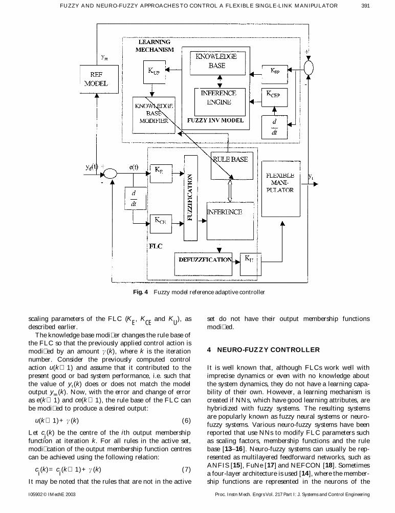
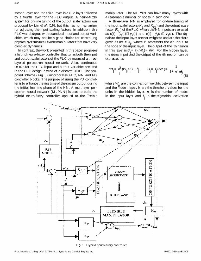
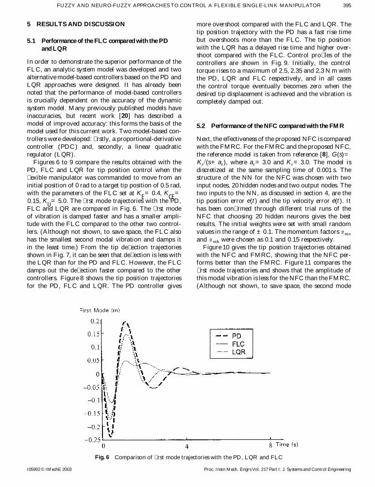
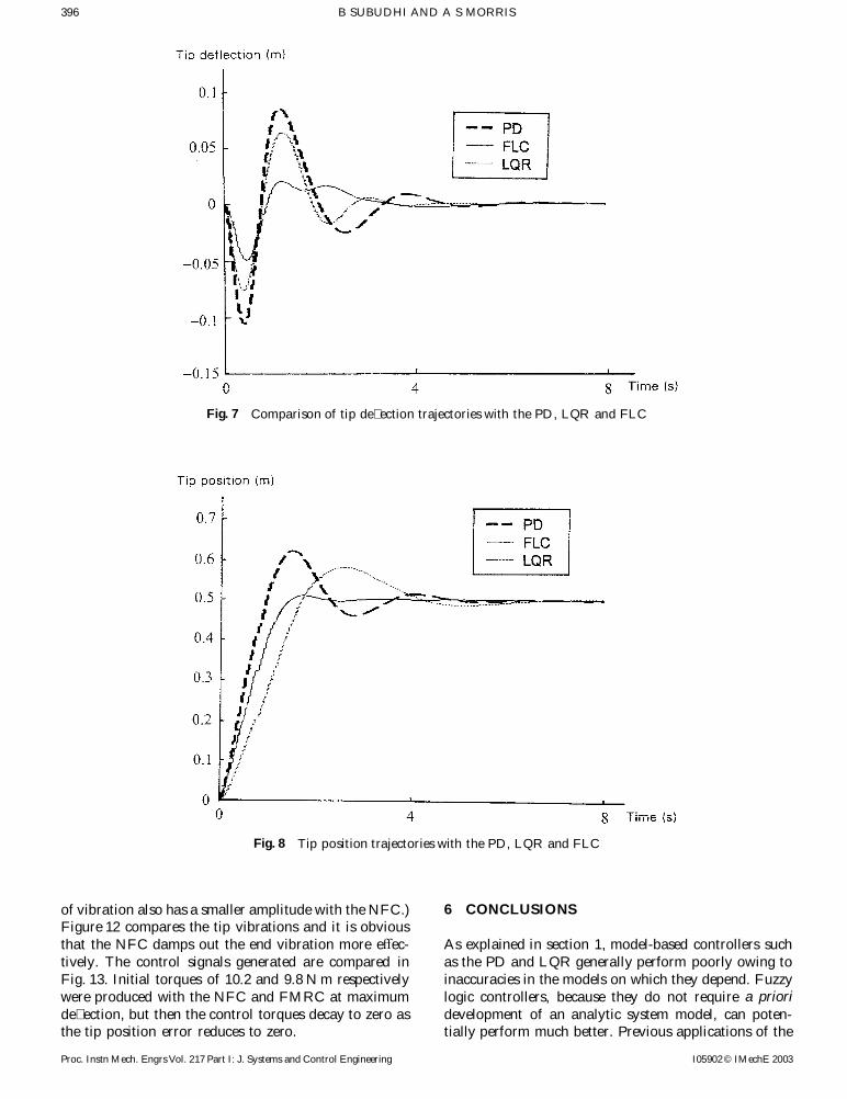
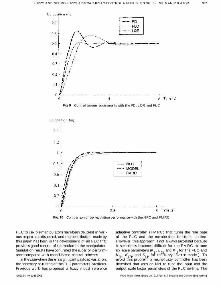
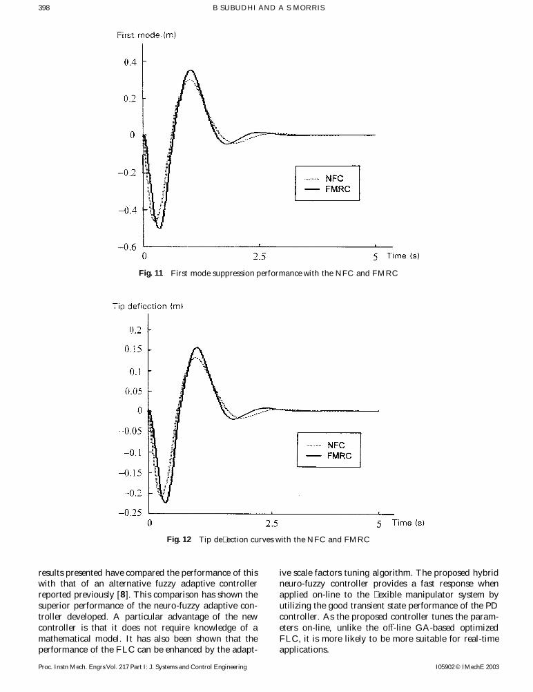
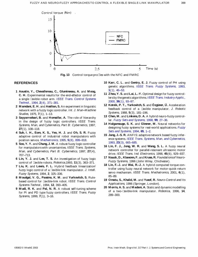