Embed Size (px)
Citation preview

USER'S MANUAL
FX3U-32DP PROFIBUS-DP Interface Block


Safety Precautions(Read these precautions before use.)
Before installation, operation, maintenance or inspection of this product, thoroughly read through andunderstand this manual and all of the associated manuals. Also, take care to handle the module properly andsafely.
This manual classifies the safety precautions into two categories: and .
Depending on the circumstances, procedures indicated by may also cause severe injury. It isimportant to follow all precautions for personal safety.Store this manual in a safe place so that it can be taken out and read whenever necessary. Always forward itto the end user.
1. DESIGN PRECAUTIONS
Indicates that incorrect handling may cause hazardous conditions, resulting indeath or severe injury.
Indicates that incorrect handling may cause hazardous conditions, resulting inmedium or slight personal injury or physical damage.
Reference Page
• Make sure to have the following safety circuits outside of the PLC to ensure safe system operationeven during external power supply problems or PLC failure.Otherwise, malfunctions may cause serious accidents.1) Most importantly, have the following: an emergency stop circuit, a protection circuit, an
interlock circuit for opposite movements (such as normal vs. reverse rotation), and an interlockcircuit (to prevent damage to the equipment at the upper and lower positioning limits).
2) Note that when the PLC CPU detects an error, such as a watchdog timer error, during self-diagnosis, all outputs are turned off. Also, when an error that cannot be detected by the PLCCPU occurs in an input/output control block, output control may be disabled.External circuits and mechanisms should be designed to ensure safe machinery operation insuch a case.
3) Note that when an error occurs in a relay, triac or transistor output device, the output could beheld either on or off.For output signals that may lead to serious accidents, external circuits and mechanismsshould be designed to ensure safe machinery operation in such a case.
2023
Reference Page
• Make sure to observe the following precautions in order to prevent any damage to the machineryor accidents due to abnormal data written to the PLC under the influence of noise:1) Do not bundle the main circuit line together with or lay it close to the main circuit, high-voltage
line, or load line. Otherwise, noise disturbance and/or surge induction are likely to take place.As a guideline, lay the control line at least 100mm (3.94") or more away from the main circuit,high-voltage line, or load line.
2) Ground the shield wire or shield of the shielded cable at one point on the PLC. However, donot ground them at the same point as the high-voltage lines.
• Install module so that excessive force will not be applied to peripheral device connectors.Failure to do so may result in wire damage/breakage or PLC failure.
202327
(i)

Safety Precautions(Read these precautions before use.)
2. INSTALLATION PRECAUTIONS
3. WIRING PRECAUTIONS
Reference Page
• Make sure to cut off all phases of the power supply externally before attempting installation orwiring work.Failure to do so may cause electric shock.
23
Reference Page
• Use the product within the generic environment specifications described in the PLC main unitmanual (Hardware Edition).Never use the product in areas with dust, oily smoke, conductive dusts, corrosive gas (salt air, Cl2,H2S, SO2, or NO2), flammable gas, vibration or impacts, or exposed to high temperature,condensation, or wind and rain.If the product is used in such conditions, electric shock, fire, malfunction, deterioration or damagemay occur.
• Install the product securely using a DIN rail or mounting screws.• Install the product on a flat surface.
If the mounting surface is rough, undue force will be applied to the PC board, thereby causingnonconformities.
• When drilling screw holes or wiring, make sure cutting or wire debris does not enter the ventilationslits.Failure to do so may cause fire, equipment failures or malfunctions.
• Be sure to remove the dust proof sheet from the PLC's ventilation port when the installation work iscompleted.Failure to do so may cause fire, equipment failures, and malfunctions.
• Do not touch the conductive parts of the product directly to avoid failure or malfunctions.
23
Reference Page
• Cut off all phases of the power supply externally before installation or wiring work in order to avoiddamage to the product or electric shock. 27
Reference Page
• When drilling screw holes or wiring, make sure cutting or wire debris does not enter the ventilationslits.Failure to do so may cause fire, equipment failures or malfunctions.
27
(ii)

Safety Precautions(Read these precautions before use.)
4. STARTUP AND MAINTENANCE PRECAUTIONS
5. DISPOSAL PRECAUTIONS
6. TRANSPORTATION AND STORAGE PRECAUTIONS
Reference Page
• Do not touch any terminal while the PLC’s power is on.Doing so may cause electric shock or malfunctions.
• Before cleaning or retightening terminals, externally cut off all phases of the power supply.Failure to do so may cause electric shock.
• Before modifying or disrupting the program in operation or running the PLC, carefully read throughthis manual and the associated manuals and ensure the safety of the operation.An operation error may damage the machinery or cause accidents.
20515462
Reference Page
• Do not disassemble or modify the unit.Doing so may cause fire, equipment failures, or malfunctions.* For repair, contact your local Mitsubishi Electric representative.
• Do not drop the product or expose the product to strong impacts, as doing so may cause productdamage.
• Turn off the power to the PLC before attaching or detaching the peripheral devices.Failure to do so may cause equipment failures or malfunctions.
20515462
Reference Page
• Please contact a certified electronic waste disposal company for the environmentally saferecycling and disposal of your device. 21
Reference Page
• The PLC and peripheral devices are precision instrument. During transportation, avoid impacts.After transportation, verify the operations of the products. 21
(iii)

(iv)

FX3U-32DP PROFIBUS-DP Interface BlockUser’s Manual
FX3U-32DP PROFIBUS-DP Interface Block
User’s Manual
Foreword
This manual contains text, diagrams and explanations which will guide the reader in the correct installation, safe use and operation of the FX3U-32DP and should be read and understood before attempting to install or use the unit.Store this manual in a safe place so that you can take it out and read it whenever necessary. Always forward it to the end user.
© 2007 MITSUBISHI ELECTRIC CORPORATION
Manual number JY997D25201
Manual revision E
Date 11/2016
This manual confers no industrial property rights or any rights of any other kind, nor does it confer any patentlicenses. Mitsubishi Electric Corporation cannot be held responsible for any problems involving industrial propertyrights which may occur as a result of using the contents noted in this manual.
1

FX3U-32DP PROFIBUS-DP Interface BlockUser’s Manual
Outline Precautions• This manual provides information for the use of the FX3U-32DP. The manual has been written to be used
by trained and competent personnel. The definition of such a person or persons is as follows;a) Any engineer who is responsible for the planning, design and construction of automatic equipment
using the product associated with this manual should be of a competent nature, trained and qualifiedto the local and national standards required to fulfill that role. These engineers should be fully aware ofall aspects of safety with regards to automated equipment.
b) Any commissioning or service engineer must be of a competent nature, trained and qualified to thelocal and national standards required to fulfill that job. These engineers should also be trained in theuse and maintenance of the completed product. This includes being completely familiar with allassociated documentation for the said product. All maintenance should be carried out in accordancewith established safety practices.
c) All operators of the completed equipment should be trained to use that product in a safe andcoordinated manner in compliance to established safety practices. The operators should also befamiliar with documentation which is connected with the actual operation of the completed equipment.
Note: The term 'completed equipment' refers to a third party constructed device which contains or uses the product associated with this manual
• This product has been manufactured as a general-purpose part for general industries, and has not been designed or manufactured to be incorporated in a device or system used in purposes related to human life.
• Before using the product for special purposes such as nuclear power, electric power, aerospace, medicine or passenger movement vehicles, consult with Mitsubishi Electric.
• This product has been manufactured under strict quality control. However when installing the product where major accidents or losses could occur if the product fails, install appropriate backup or failsafe functions in the system.
• When combining this product with other products, please confirm the standard and the code, or regulations with which the user should follow. Moreover, please confirm the compatibility of this product to the system, machine, and apparatus with which the user is using.
• If in doubt at any stage during the installation of the product, always consult a professional electrical engineer who is qualified and trained to the local and national standards. If in doubt about the operation or use, please consult the nearest Mitsubishi Electric representative.
• Since the examples indicated by this manual, technical bulletin, catalog, etc. are used as a reference, please use it after confirming the function and safety of the equipment and system. Mitsubishi Electric will accept no responsibility for actual use of the product based on these illustrative examples.
• This manual content, specification etc. may be changed without a notice for improvement.• The information in this manual has been carefully checked and is believed to be accurate; however, if you
have noticed a doubtful point, a doubtful error, etc., please contact the nearest Mitsubishi Electric representative.
Registration
• Microsoft® and Windows® are either registered trademarks or trademarks of Microsoft Corporation in the United States and/or other countries.
• The company and product names described in this manual are the registered trademarks or trademarks of their respective companies.
2
FX3U-32DP PROFIBUS-DP Interface BlockUser’s Manual
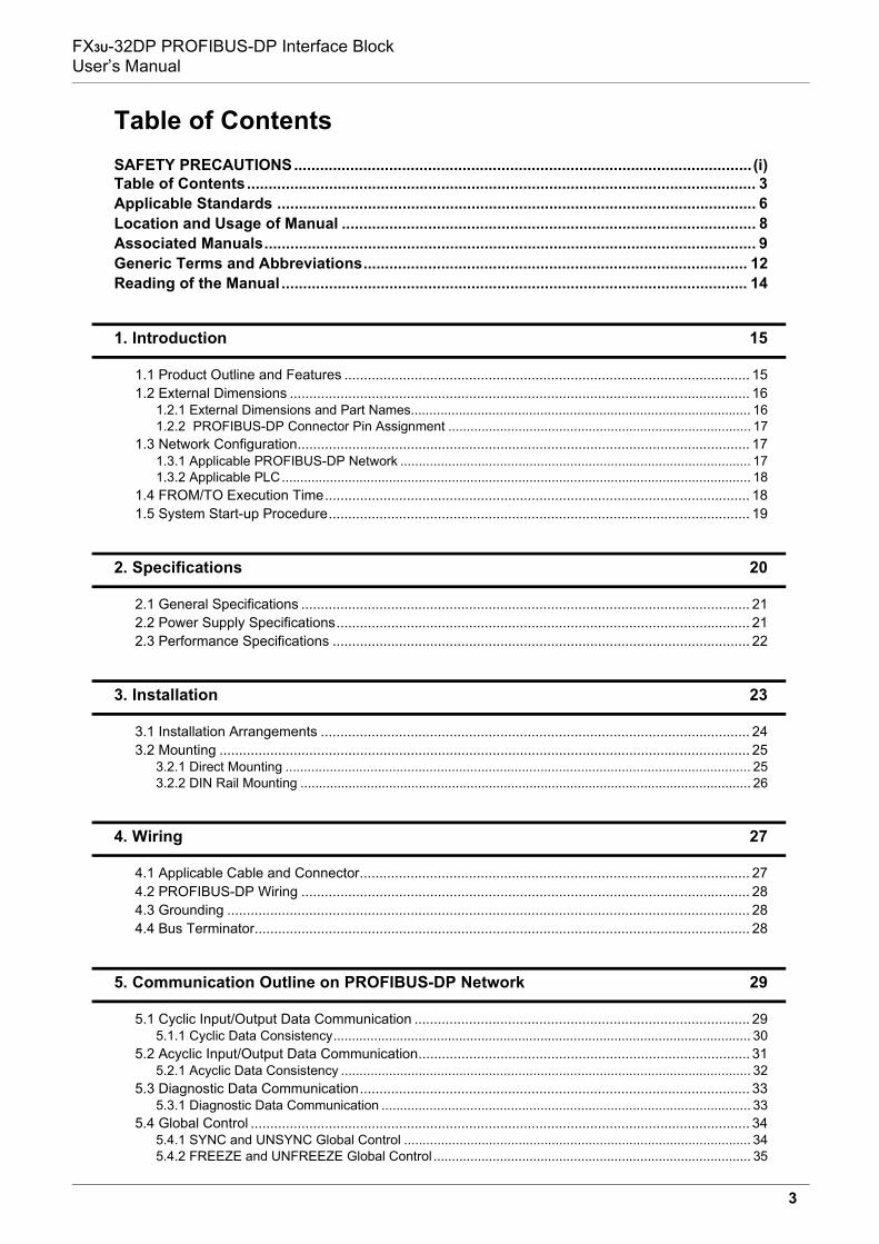
Table of ContentsSAFETY PRECAUTIONS.......................................................................................................... (i)Table of Contents...................................................................................................................... 3Applicable Standards ............................................................................................................... 6Location and Usage of Manual ................................................................................................ 8Associated Manuals.................................................................................................................. 9Generic Terms and Abbreviations......................................................................................... 12Reading of the Manual ............................................................................................................ 14
1. Introduction 15
1.1 Product Outline and Features ........................................................................................................ 151.2 External Dimensions ...................................................................................................................... 16
1.2.1 External Dimensions and Part Names............................................................................................ 161.2.2 PROFIBUS-DP Connector Pin Assignment .................................................................................. 17
1.3 Network Configuration.................................................................................................................... 171.3.1 Applicable PROFIBUS-DP Network ............................................................................................... 171.3.2 Applicable PLC............................................................................................................................... 18
1.4 FROM/TO Execution Time............................................................................................................. 181.5 System Start-up Procedure............................................................................................................ 19
2. Specifications 20
2.1 General Specifications ................................................................................................................... 212.2 Power Supply Specifications.......................................................................................................... 212.3 Performance Specifications ........................................................................................................... 22
3. Installation 23
3.1 Installation Arrangements .............................................................................................................. 243.2 Mounting ........................................................................................................................................ 25
3.2.1 Direct Mounting .............................................................................................................................. 253.2.2 DIN Rail Mounting .......................................................................................................................... 26
4. Wiring 27
4.1 Applicable Cable and Connector.................................................................................................... 274.2 PROFIBUS-DP Wiring ................................................................................................................... 284.3 Grounding ...................................................................................................................................... 284.4 Bus Terminator............................................................................................................................... 28
5. Communication Outline on PROFIBUS-DP Network 29
5.1 Cyclic Input/Output Data Communication ...................................................................................... 295.1.1 Cyclic Data Consistency................................................................................................................. 30
5.2 Acyclic Input/Output Data Communication..................................................................................... 315.2.1 Acyclic Data Consistency ............................................................................................................... 32
5.3 Diagnostic Data Communication.................................................................................................... 335.3.1 Diagnostic Data Communication .................................................................................................... 33
5.4 Global Control ................................................................................................................................ 345.4.1 SYNC and UNSYNC Global Control .............................................................................................. 345.4.2 FREEZE and UNFREEZE Global Control ...................................................................................... 35
3

FX3U-32DP PROFIBUS-DP Interface BlockUser’s Manual
6. Buffer Memory Allocation 36
6.1 Buffer Memory (BFM) List .............................................................................................................. 366.2 Cyclic I/O Data Area Compatible with FX0N-32NT-DP [BFM #0 to BFM #19] ............................... 376.3 Data Exchange Status Register [BFM #20] ................................................................................... 386.4 Swap Byte Order [BFM #21 Bit0 and Bit1]..................................................................................... 386.5 Cyclic Input Data Length [BFM #22] .............................................................................................. 386.6 Cyclic Output Data Length [BFM #23]............................................................................................ 386.7 Transmission Speed [BFM #24]..................................................................................................... 396.8 DP Communication Status Register [BFM #25] ............................................................................. 396.9 PROFIBUS Module ID [BFM #26].................................................................................................. 406.10 Slave Address [BFM #27] ............................................................................................................ 406.11 User Diagnostics [BFM #28] ........................................................................................................ 406.12 Error Status Register [BFM #29 Bit0 to Bit13].............................................................................. 416.13 Module ID Code [BFM #30].......................................................................................................... 416.14 Master Address [BFM #33] .......................................................................................................... 416.15 Allocated Group ID Number [BFM #34] ....................................................................................... 426.16 DP-V1 Communication Parameter [BFM #35] ............................................................................. 426.17 Start/Stop DP Communication [BFM #36 Bit0] ............................................................................ 436.18 Consistency Handling Error Flags [BFM #37] .............................................................................. 436.19 Setting Error Flag [BFM #38] ....................................................................................................... 446.20 Cyclic Input Data Consistency Activate/Deactivate Flag [BFM #98 Bit0]..................................... 456.21 Cyclic Input Data Send Flag [BFM #99 Bit0]................................................................................ 456.22 Cyclic Input Data Send Area [BFM #100 to #171] ....................................................................... 456.23 Cyclic Output Data Consistency Activate/Deactivate Flag [BFM #298 Bit0] ................................ 456.24 Cyclic Output Data Read Flag [BFM #299 Bit0]........................................................................... 456.25 Cyclic Output Data Receive Area [BFM #300 to #371] ................................................................ 466.26 Acyclic Input Data Send Flag (Class1) [BFM #499 Bit0].............................................................. 466.27 Acyclic Input Data Send Area (Class1) [BFM #500 to #572] ....................................................... 466.28 Acyclic Output Data Read Flag (Class1) [BFM #699 Bit0]........................................................... 466.29 Acyclic Output Data Receive Area (Class1) [BFM #700 to #772] ................................................ 476.30 Acyclic Input Data Send Flag (Class2) [BFM #899 Bit0].............................................................. 476.31 Acyclic Input Data Send Area (Class2) [BFM #900 to #972] ....................................................... 476.32 Acyclic Output Data Read Flag (Class2) [BFM #1099 Bit0]......................................................... 476.33 Acyclic Output Data Receive Area (Class2) [BFM #1100 to #1172] ............................................ 486.34 Reset Extended Diagnostic/Alarm Data Area Flag [BFM #1298]................................................. 486.35 Alarm/Status Switch [BFM #1299 Bit0] ........................................................................................ 486.36 Diagnostic/Alarm Immediate Send Flag [BFM #1300 Bit0] .......................................................... 496.37 Diagnostic/Alarm (Status) Data Area ........................................................................................... 49
6.37.1 Master Address [BFM #1301]....................................................................................................... 496.37.2 ID Number [BFM #1302]............................................................................................................... 496.37.3 Block Length [BFM # 1303] .......................................................................................................... 506.37.4 Alarm/Status Type [BFM #1304] .................................................................................................. 506.37.5 Slot Number [BFM #1305] ............................................................................................................ 506.37.6 Specifier [BFM #1306] .................................................................................................................. 506.37.7 Extended Alarm Data [BFM #1307].............................................................................................. 506.37.8 Extended Alarm Data [BFM #1308].............................................................................................. 506.37.9 Extended Diagnostic/Alarm(Status) Data Area [BFM #1309 to #1322]........................................ 50
4

FX3U-32DP PROFIBUS-DP Interface BlockUser’s Manual
7. Parameter Setting and Network Configuration [GX Configurator-DP] 51
7.1 Slave Parameter Settings .............................................................................................................. 527.1.1 Slave Properties ............................................................................................................................. 527.1.2 Extended User Parameters ............................................................................................................ 527.1.3 Slave Modules................................................................................................................................ 53
7.2 Network Configuration.................................................................................................................... 53
8. Example Program 54
8.1 Example Program .......................................................................................................................... 548.1.1 System Configuration ..................................................................................................................... 548.1.2 Contents of Operation .................................................................................................................... 548.1.3 Setting Network Configuration and Parameter for Example Program............................................ 558.1.4 Example Program for Cyclic Communication using GX Developer................................................ 588.1.5 Example Program for Cyclic Communication using GX IEC Developer (Ver. 7.00 or later)........... 598.1.6 Example Program for Acyclic Communication using GX Developer .............................................. 608.1.7 Example Program for Acyclic Communication using GX IEC Developer (Ver. 7.00 or later) ......... 61
9. Diagnostics 62
9.1 Check LEDs ................................................................................................................................... 639.2 Checking Errors ............................................................................................................................. 64
Warranty................................................................................................................................... 65Revised History ....................................................................................................................... 66
5

FX3U-32DP PROFIBUS-DP Interface BlockUser’s Manual Applicable Standards
Applicable Standards
Certification of UL, cUL StandardsThe following product has UL and cUL certification.
Compliance with EC Directive (CE Marking)This note does not guarantee that an entire mechanical module produced in accordance with the contents ofthis note will comply with the following standards.Compliance to EMC and LVD directives for the entire mechanical module should be checked by the user /manufacturer. For more details please contact your local Mitsubishi Electric sales site.
1. Requirement for Compliance with EMC DirectiveThe following products have shown compliance through direct testing (of the identified standards below) anddesign analysis (through the creation of a technical construction file) to the European Directive forElectromagnetic Compatibility (2014/30/EU) when used as directed by the appropriate documentation.
AttentionThis product is designed for use in industrial applications.
UL, cUL File Number: E95239Models: FX3U-32DP
Type: Programmable Controller (Open Type Equipment)Models: MELSEC FX3U series products, identified here, manufactured from
March 1st, 2007. FX3U-32DP
Standard TestsEN61131-2:2007Programmable controller
- Equipment requirements and tests
Compliance with all relevant aspects of the standard.EMI• Radiated Emission• Conducted EmissionEMS• Radiated electromagnetic field• Fast transient burst• Electrostatic discharge• High-energy surge• Voltage drops and interruptions• Conducted RF• Power frequency magnetic field
6

FX3U-32DP PROFIBUS-DP Interface BlockUser’s Manual Applicable Standards
Caution for Compliance with EC Directive
1) Caution for wiringFor noise prevention please attach at least 50 mm (1.97") of the twisted-pair cable along the groundingplate to which the ground terminal is connected.
→ For wiring details, refer to Section 4.22) Installation in Enclosure
→ For details on installation in Enclosure of FX3G Series PLC,refer to FX3G User’s Manual - Hardware Edition.
→ For details on installation in Enclosure of FX3GC*1 Series PLC,refer to FX3GC User’s Manual - Hardware Edition.
→ For details on installation in Enclosure of FX3U Series PLC,refer to FX3U User’s Manual - Hardware Edition.
→ For details on installation in Enclosure of FX3UC*1 Series PLC,refer to FX3UC User’s Manual - Hardware Edition.
→ For details on installation in Enclosure of FX5U*2 PLC,refer to MELSEC iQ-F FX5U User’s Manual (Hardware).
→ For details on installation in Enclosure of FX5UC*2 PLC,refer to MELSEC iQ-F FX5UC User’s Manual (Hardware).
*1. An FX2NC-CNV-IF or FX3UC-1PS-5V is necessary to connect to the 32DP with the FX3GC/FX3UC SeriesPLC.However, the FX3U-32DP cannot be connected to the FX3UC-32MT-LT(-2).
*2. An FX5-CNV-BUS or FX5-CNV-BUSC is necessary to connect to the 32DP with the FX5U/FX5UCPLC.
7

FX3U-32DP PROFIBUS-DP Interface BlockUser’s Manual Location and Usage of Manual
Location and Usage of ManualThe FX3U-32DP PROFIBUS-DP Interface Block is a DP-Slave for the PROFIBUS-DP network. By connectingthe FX3U-32DP, the FX3G/FX3GC*1/FX3U/FX3UC*1/FX5U*2/FX5UC*2 PLC can both read and write data fromand to a DP-Master.
PROFIBUS-DP Slave
PLC
For installation and wiring
Supplied Manual
Additional Manual
- Hardware Manual(Manual is supplied with product.)
- User's Manual - Hardware Edition
For basic/applied instructions and PLC devices
- Programming Manual - Basic & Applied Instruction EditionAdditional Manual
PROFIBUS-DP Master
FX3U-64DP-M
This manual
The installation manual is supplied with the product.For details, refer to the user's manual.For installation and wiring
- FX3U-64DP-M Installation Manual(Manual is supplied with product.)
For details
- FX3U-64DP-M User's Manual
Supplied Manual
Additional Manual
This manual details wiring, installation, specification and BFM allocation, etc.
FX3U-32DP The hardware manual is supplied with the product.For details, refer to the user's manual.
For installation and wiring
- Installation Manual(Manual is supplied with product.)
For details
- User's Manual
Supplied Manual
Additional Manual
Obtain the manual of another PROFIBUS-DP master module to fulfill its requirementsfor your network.
For other master modules
If necessary, obtain the following manuals for your network.
8

FX3U-32DP PROFIBUS-DP Interface BlockUser’s Manual Associated Manuals
Associated ManualsFor a detailed explanation of the FX3U-32DP, refer to this manual.For hardware information and instructions on the PLC main unit/CPU Module, other special function units/blocks, etc., refer to the appropriate manuals.For acquiring required manuals, contact the distributor from where your product was purchased.
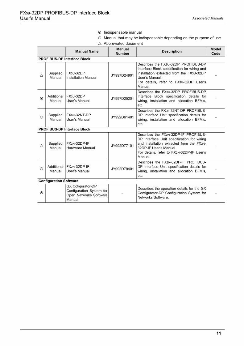
Indispensable manualManual that may be indispensable depending on the purpose of useAbbreviated document
Manual Name Manual Number Description Model
CodeManual for the Main Unit/CPU ModuleFX3G/FX3GC/FX3U/FX3UC Series PLCs Main Unit
Supplied Manual
FX3G Series Hardware Manual JY997D46001
Describes FX3G Series PLC specification forI/O, wiring and installation extracted from theFX3G User’s Manual - Hardware Edition.For details, refer to FX3G Series User’sManual - Hardware Edition.
−
Additional Manual
FX3G Series User’s Manual - Hardware Edition
JY997D31301Describes FX3G Series PLC specificationdetails for I/O, wiring, installation andmaintenance.
09R521
Supplied Manual
FX3GC Series Hardware Manual JY997D45201
Describes FX3GC Series PLC specificationfor I/O, wiring and installation extracted fromthe FX3GC User’s Manual - HardwareEdition.For details, refer to FX3GC Series User’sManual - Hardware Edition.
−
Additional Manual
FX3GC Series User’s Manual - Hardware Edition
JY997D45401Describes FX3GC Series PLC specificationdetails for I/O, wiring, installation andmaintenance.
09R533
Supplied Manual
FX3U Series Hardware Manual JY997D50301
Describes FX3U Series PLC specification forI/O, wiring and installation extracted from theFX3U User’s Manual - Hardware Edition.For details, refer to FX3U Series User’sManual - Hardware Edition.
−
Additional Manual
FX3U Series User’s Manual - Hardware Edition
JY997D16501Describes FX3U Series PLC specificationdetails for I/O, wiring, installation andmaintenance.
09R516
Supplied Manual
FX3UC (D, DS, DSS) Series Hardware Manual
JY997D50501
Describes FX3UC (D, DS, DSS) Series PLCspecification for I/O, wiring and installationextracted from the FX3UC User’s Manual -Hardware Edition.For details, refer to FX3UC Series User’sManual - Hardware Edition.
−
Additional Manual
FX3UC Series User’s Manual - Hardware Edition
JY997D28701Describes FX3UC Series PLC specificationdetails for I/O, wiring, installation andmaintenance.
09R519
FX5U/FX5UC PLCs CPU Module
Supplied Manual
MELSEC iQ-F FX5U CPU Module Hardware Manual
JY997D53401
Describes FX5U PLC specification for I/O,wiring and installation extracted from theMELSEC iQ-F FX5U User’s Manual(Hardware).For details, refer to MELSEC iQ-F FX5UUser’s Manual (Hardware).
−
Additional Manual
MELSEC iQ-F FX5U User’s Manual (Hardware)
JY997D55301 Describes FX5U PLC specification detailsfor I/O, wiring, installation and maintenance. 09R536
9

FX3U-32DP PROFIBUS-DP Interface BlockUser’s Manual Associated Manuals
Supplied Manual
MELSEC iQ-F FX5UC CPU Module Hardware Manual
JY997D61001
Describes FX5UC PLC specification for I/O,wiring and installation extracted from theMELSEC iQ-F FX5UC User’s Manual(Hardware).For details, refer to MELSEC iQ-F FX5UCUser’s Manual (Hardware).
−
Additional Manual
MELSEC iQ-F FX5UC User’s Manual (Hardware)
JY997D61401 Describes FX5UC PLC specification detailsfor I/O, wiring, installation and maintenance. 09R558
Programming
Additional Manual
FX3S/FX3G/FX3GC/FX3U/FX3UC Series Programming Manual - Basic & Applied Instruction Edition
JY997D16601 Describes PLC programming for basic/applied instructions and devices. 09R517
Additional Manual
MELSEC-Q/L/FStructured ProgrammingManual (Fundamentals)
SH-080782
This manual contains explanations for the programming method, types of programming languages and other information required to create structured programs.
13JW06
Additional Manual
FX CPU Structured Programming Manual (Device & Common)
JY997D26001This manual contains explanations for the devices and parameters provided in GX Works2 for structured programming.
09R925
Additional Manual
FX CPU Structured Programming Manual (Basic & Applied Instruction)
JY997D34701This manual contains explanations for the sequence instructions provided in GX Works2 for structured programming.
09R926
Additional Manual
FX CPU Structured Programming Manual (Application Functions)
JY997D34801This manual contains explanations for the application functions provided in GX Works2 for structured programming.
09R927
Additional Manual
MELSEC iQ-F FX5 Programming Manual (Program Design)
JY997D55701 Describes specifications of ladders, ST,FBD/LD, and other programs and labels. 09R538
Additional Manual
MELSEC iQ-F FX5 Programming Manual (Instructions, Standard Functions/Function Blocks)
JY997D55801Describes specifications of instructionsand functions that can be used in programs.
09R539
Manual for the PROFIBUS-DP Master Block, Interface BlockPROFIBUS-DP Master Block
Supplied Manual
FX3U-64DP-M Installation Manual JY997D19901
Describes the FX3U-64DP-M PROFIBUS-DP Master Block specification for wiringand installation extracted from the FX3U-64DP-M User’s Manual. For details, refer to FX3U-64DP-M User’sManual.
−
Additional Manual
FX3U-64DP-M User’s Manual JY997D19201
Describes the FX3U-64DP-M PROFIBUS-DP Master Block specification details forwiring, installation and allocation BFM’s,etc.
−
Indispensable manualManual that may be indispensable depending on the purpose of useAbbreviated document
Manual Name Manual Number Description Model
Code
10
FX3U-32DP PROFIBUS-DP Interface BlockUser’s Manual Associated Manuals
PROFIBUS-DP Interface Block
Supplied Manual
FX3U-32DP Installation Manual JY997D24901
Describes the FX3U-32DP PROFIBUS-DPInterface Block specification for wiring andinstallation extracted from the FX3U-32DPUser’s Manual. For details, refer to FX3U-32DP User’sManual.
−
Additional Manual
FX3U-32DP User’s Manual JY997D25201
Describes the FX3U-32DP PROFIBUS-DPInterface Block specification details forwiring, installation and allocation BFM’s,etc.
−
Supplied Manual
FX0N-32NT-DP User’s Manual JY992D61401
Describes the FX0N-32NT-DP PROFIBUS-DP Interface Unit specification details forwiring, installation and allocation BFM’s,etc.
−
PROFIBUS-DP Interface Block
Supplied Manual
FX2N-32DP-IF Hardware Manual JY992D77101
Describes the FX2N-32DP-IF PROFIBUS-DP Interface Unit specification for wiringand installation extracted from the FX2N-32DP-IF User’s Manual. For details, refer to FX2N-32DP-IF User’sManual.
−
Additional Manual
FX2N-32DP-IF User’s Manual JY992D79401
Describes the FX2N-32DP-IF PROFIBUS-DP Interface Unit specification details forwiring, installation and allocation BFM’s,etc.
−
Configuration SoftwareGX Cofigurator-DP Configuration System forOpen Networks SoftwareManual
−Describes the operation details for the GXConfigurator-DP Configuration System forNetworks Software.
−
Indispensable manualManual that may be indispensable depending on the purpose of useAbbreviated document
Manual Name Manual Number Description Model
Code
11
FX3U-32DP PROFIBUS-DP Interface BlockUser’s Manual Generic Terms and Abbreviations
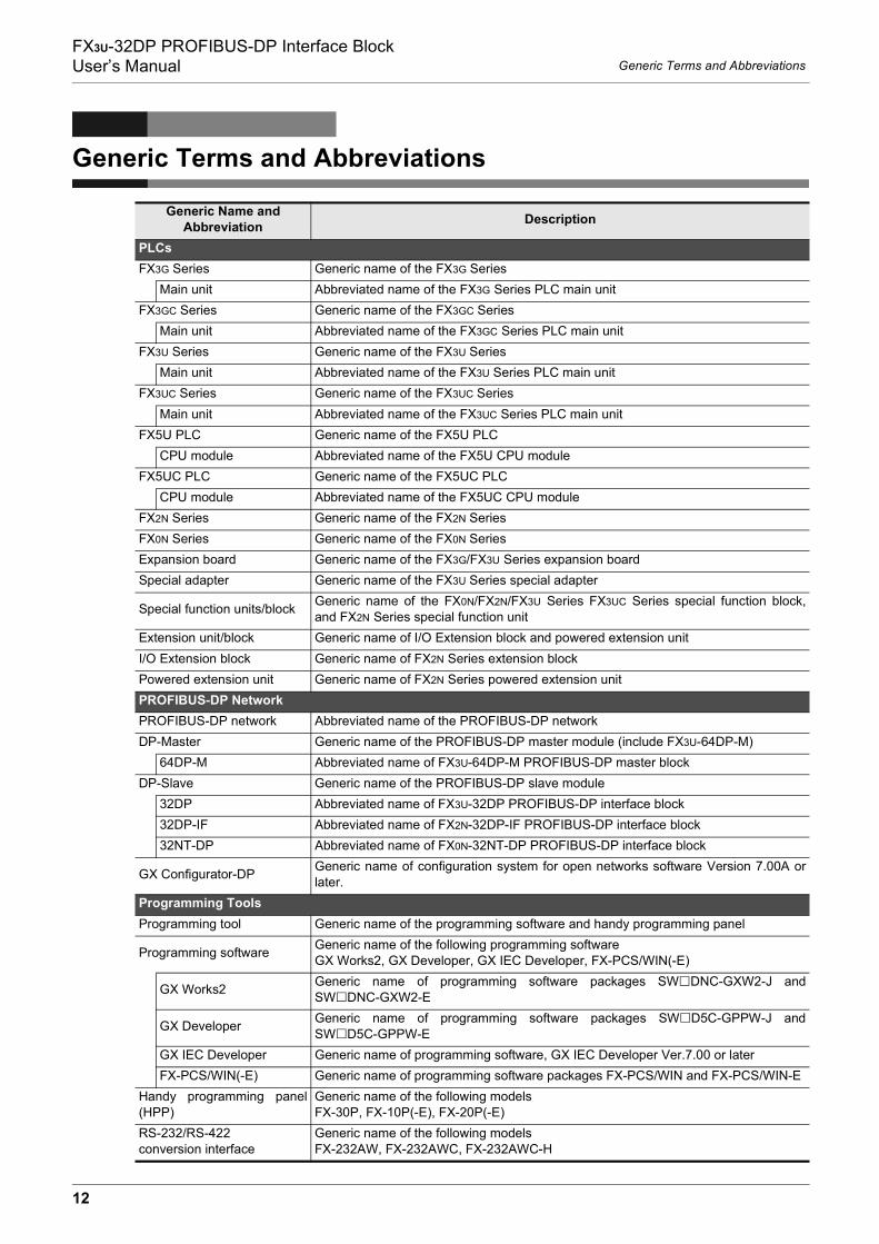
Generic Terms and Abbreviations
Generic Name and Abbreviation Description
PLCsFX3G Series Generic name of the FX3G Series
Main unit Abbreviated name of the FX3G Series PLC main unitFX3GC Series Generic name of the FX3GC Series
Main unit Abbreviated name of the FX3GC Series PLC main unitFX3U Series Generic name of the FX3U Series
Main unit Abbreviated name of the FX3U Series PLC main unitFX3UC Series Generic name of the FX3UC Series
Main unit Abbreviated name of the FX3UC Series PLC main unitFX5U PLC Generic name of the FX5U PLC
CPU module Abbreviated name of the FX5U CPU moduleFX5UC PLC Generic name of the FX5UC PLC
CPU module Abbreviated name of the FX5UC CPU moduleFX2N Series Generic name of the FX2N SeriesFX0N Series Generic name of the FX0N SeriesExpansion board Generic name of the FX3G/FX3U Series expansion boardSpecial adapter Generic name of the FX3U Series special adapter
Special function units/block Generic name of the FX0N/FX2N/FX3U Series FX3UC Series special function block,and FX2N Series special function unit
Extension unit/block Generic name of I/O Extension block and powered extension unitI/O Extension block Generic name of FX2N Series extension blockPowered extension unit Generic name of FX2N Series powered extension unitPROFIBUS-DP NetworkPROFIBUS-DP network Abbreviated name of the PROFIBUS-DP networkDP-Master Generic name of the PROFIBUS-DP master module (include FX3U-64DP-M)
64DP-M Abbreviated name of FX3U-64DP-M PROFIBUS-DP master blockDP-Slave Generic name of the PROFIBUS-DP slave module
32DP Abbreviated name of FX3U-32DP PROFIBUS-DP interface block32DP-IF Abbreviated name of FX2N-32DP-IF PROFIBUS-DP interface block32NT-DP Abbreviated name of FX0N-32NT-DP PROFIBUS-DP interface block
GX Configurator-DP Generic name of configuration system for open networks software Version 7.00A orlater.
Programming ToolsProgramming tool Generic name of the programming software and handy programming panel
Programming software Generic name of the following programming softwareGX Works2, GX Developer, GX IEC Developer, FX-PCS/WIN(-E)
GX Works2 Generic name of programming software packages SW DNC-GXW2-J andSW DNC-GXW2-E
GX Developer Generic name of programming software packages SW D5C-GPPW-J andSW D5C-GPPW-E
GX IEC Developer Generic name of programming software, GX IEC Developer Ver.7.00 or laterFX-PCS/WIN(-E) Generic name of programming software packages FX-PCS/WIN and FX-PCS/WIN-E
Handy programming panel(HPP)
Generic name of the following modelsFX-30P, FX-10P(-E), FX-20P(-E)
RS-232/RS-422 conversion interface
Generic name of the following modelsFX-232AW, FX-232AWC, FX-232AWC-H
12

FX3U-32DP PROFIBUS-DP Interface BlockUser’s Manual Generic Terms and Abbreviations
USB/RS-422 conversion interface Abbreviated name of the FX-USB-AW USB/RS-422 Conversion Interface
Manuals
Programming Manual
Generic name for FX3S/FX3G/FX3GC/FX3U/FX3UC Series Programming Manual -Basic & Applied Instruction Edition, MELSEC iQ-F FX5 Programming Manual(Program Design), and MELSEC iQ-F FX5 Programming Manual (Instructions,Standard Functions/Function Blocks)
FX3G PLC Hardware Edition Abbreviated name of FX3G Series User's Manual - Hardware EditionFX3GC Hardware Edition Abbreviated name of FX3GC Series User's Manual - Hardware EditionFX3U PLC Hardware Edition Abbreviated name of FX3U Series User's Manual - Hardware EditionFX3UC PLC Hardware Edition Abbreviated name of FX3UC Series User's Manual - Hardware Edition
Analog Control Edition Abbreviated name of FX3S/FX3G/FX3GC/FX3U/FX3UC Series User's Manual - AnalogControl Edition
Positioning Control Edition Abbreviated name of FX3S/FX3G/FX3GC/FX3U/FX3UC Series User's Manual -Positioning Control Edition
Data Communication Edition Abbreviated name of FX Series User's Manual - Data Communication EditionGX Configurator-DP Software Manual
Abbreviated name of GX Cofigurator-DP Configuration System for Open NetworksSoftware Manual
Generic Name and Abbreviation Description
13

FX3U-32DP PROFIBUS-DP Interface BlockUser’s Manual Reading of the Manual
Reading of the Manual
The page above is an example. It may differ from the actual page.
25
FX3U-32DP PROFIBUS-DP Interface BlockUser’s Manual
3 Installation3.2 Mounting
1
Introduction
2
Specifications
3
Installation
4
Wiring
5
Comm. Outline on PROFIBUS-DP Network
6
Buffer Mem
oryAllocation
7
Parameter Setting and Network Configuration
8
Example
Program
9
Diagnostics
3.2 Mounting
The 32DP can be mounted on a DIN rail (DIN46227) or mounted directly to the mounting surface with screws.
3.2.1 Direct Mounting
The 32DP can be directly mounted with M4 screws. The 32DP mounting hole pitches are shown below.
For the connecting procedure to the extension port of the FX3G Series PLC,refer to FX3G PLC Hardware Edition
For the connecting procedure to the extension port of the FX3GC Series PLC,refer to FX3GC PLC Hardware Edition
For the connecting procedure to the extension port of the FX3U Series PLC,refer to FX3U PLC Hardware Edition
For the connecting procedure to the extension port of the FX3UC Series PLC,refer to FX3UC PLC Hardware Edition
For the connecting procedure to the extension port of the FX5U PLC,refer to MELSEC iQ-F FX5U User's Manual (Hardware)
For the connecting procedure to the extension port of the FX5UC PLC,refer to MELSEC iQ-F FX5UC User's Manual (Hardware)
Note
• Mounting screw: M4 screw.• An interval space between each unit of 1 to 2 mm (0.04" to 0.08") is necessary.• When connecting the 32DP to an extension unit/block (or special function unit/block), first mount the
extension unit/block (or special function unit/block) to the right side of the PLC.Direct Mounting
1) Drill screw holes on the mounting surface according to thediagram above.
2) Align the 32DP (right fig. A) with the holes and tighten withM4 screws (right fig. B).
3) Connect the 32DP’s extension cable (right fig. C) to theextension device connector of the main unit.For extension cable connection procedures of the FX3G
Series PLC, refer to FX3G PLC Hardware EditionFor extension cable connection procedures of the FX3GC
Series PLC, refer to FX3GC PLC Hardware EditionFor extension cable connection procedures of the FX3U
Series PLC, refer to FX3U PLC Hardware EditionFor extension cable connection procedures of the FX3UC
Series PLC, refer to FX3UC PLC Hardware EditionFor extension cable connection procedures of the FX5U PLC,
refer to MELSEC iQ-F FX5U User's Manual (Hardware)For extension cable connection procedures of the FX5UC PLC,
refer to MELSEC iQ-F FX5UC User's Manual (Hardware)
4(0.16")
39(1.54")
80 (3
.15"
)
90 (3
.55"
)
FX3U-48MFX3U
RUN
POWER
ERROR
BATT
FX3U
ERROR
RUNBATT
POWER
0
31
2IN
OUT
64
5
217 20
24
22 23
2625
10 1113
12
16
14 1517
270
31
2
64
5
217 20
24
22 23
2625
10 1113
12
16
14 1517
27
B
A
B
Shows the title of the chapter and the title of the section.This area shows the title of the chapter and the title of the section for the page currently opened.
This area shows the manual title for the page currently opened.
Indexes the chapter number.The right side of each page indexes the chapter number for the page currently opened.
The mark of " " is expressing the reference destination and the reference manual.
Shows the reference.
Shows the manual title.
14

FX3U-32DP PROFIBUS-DP Interface BlockUser’s Manual
1 Introduction1.1 Product Outline and Features
1
Introduction
2
Specifications
3
Installation
4
Wiring
5
Comm. Outline on PROFIBUS-DP Network
6
Buffer Mem
oryAllocation
7
Parameter Setting and Network Configuration
8
Example
Program
9
Diagnostics
1. Introduction
1.1 Product Outline and Features
The FX3U-32DP PROFIBUS-DP Interface Block (hereinafter called 32DP) enables users to integrate theMELSEC FX3G/FX3GC*1/FX3U/FX3UC*1/FX5U*2/FX5UC*2 PLC in any existing PROFIBUS-DP network (DP-V0/DP-V1) as a DP-Slave. The 32DP links the FX3G/FX3GC*1/FX3U/FX3UC*1/FX5U*2/FX5UC*2 PLC withPROFIBUS-DP decentralized control tasks. The module connects the PLC system to the DP-Master in thePROFIBUS-DP network for efficient and easy data exchange.
*1. An FX2NC-CNV-IF or FX3UC-1PS-5V is necessary to connect to the 32DP with the FX3GC/FX3UCSeries PLC.However, the 32DP cannot be connected to the FX3UC-32MT-LT(-2).
*2. An FX5-CNV-BUS or FX5-CNV-BUSC is necessary to connect to the 32DP with the FX5U/FX5UCPLC.
1. Easy Connectivity to an existing PROFIBUS-DP NetworkThe 32DP Interface Module enables the FX3G/FX3GC*1/FX3U/FX3UC*1/FX5U*2/FX5UC*2 PLC to fit into anexisting PROFIBUS-DP Network as a DP-Slave, while reducing the time and cost for users to build up a newnetwork system.
→ For the PROFIBUS-DP Network configuration, refer to Subsection 1.3.1*1. An FX2NC-CNV-IF or FX3UC-1PS-5V is necessary to connect to the 32DP with the FX3GC/FX3UC
Series PLC.However, the 32DP cannot be connected to the FX3UC-32MT-LT(-2).
*2. An FX5-CNV-BUS or FX5-CNV-BUSC is necessary to connect to the 32DP with the FX5U/FX5UCPLC.
2. Enhanced Data ExchangeThe 32DP has enhanced the data exchange functionality in the following communication formats.
→ For details, refer to Chapter 5 and 6• Cyclic Input/Output Data Communication - a maximum of 144 Bytes• Acyclic Input/Output Data Communication - a maximum of 140 Bytes• User-Diagnostic Messages• Alarm(Status) Messages
3. Global ControlThe 32DP supports SYNC / UNSYNC / FREEZE / UNFREEZE global controls.
→ For details, refer to Chapter 5
4. Flexible and Easy Network SettingThe 32DP enables a flexible and smooth integration with components on a new/existing PROFIBUS-DPNetwork. The FX3U-32DP PROFIBUS Interface Block is fully applicable for the user-specific PROFIBUS-DPNetwork.
→ For details, refer to Chapter 7 and 8
5. Various Transmission Speed OptionsThe 32DP supports the communication speeds, 9.6k, 19.2k, 45.45k, 93.75k, 187.5k, 500k, 1.5M, 3M, 6M and12Mbps to fit into various kinds of networks. To connect the 32DP to a PROFIBUS-DP Network, use thestandard 9-pin D-SUB connector and shielded twisted-pair PROFIBUS cable complying with EN50170.
→ For wiring, refer to Chapter 4→ For the transmission speed parameter, refer to Section 2.3 and 6.7
Note : INPUT/OUTPUT to where?
When this manual references INPUT/OUTPUT for communication data on the PROFIBUS-DP network, it refers to data from the DP-Master's point of view. Therefore, CYCLIC INPUT DATA means THE CYCLIC DATA STREAMING FROM DP-SLAVE TO DP-MASTER. On the other hand, ACYCLIC OUTPUT DATA, for example, means THE ACYCLIC DATA STREAMING FROM DP-MASTER TO DP-SLAVE.
15

FX3U-32DP PROFIBUS-DP Interface BlockUser’s Manual
1 Introduction1.2 External Dimensions
1.2 External Dimensions
1.2.1 External Dimensions and Part Names
[1] PROFIBUS-DP port (9-pin D-SUB Connector: #4-40unc inch screw thread)[2] Extension cable
[3] Direct mounting hole: 2-φ4.5 (0.18"), mounting screw: M4 screw[4] Status LEDs
→ For details on the status LEDs, refer to Section 9.1
[5] Extension port under the top cover[6] Name plate[7] DIN rail mounting groove (DIN rail: DIN46277)[8] DIN rail mounting hook
LED Name Color Description
POWER Green
ON :The connected PLC supplies power to the 32DP correctlyOFF :Power is being supplied incorrectly from the PLC to the 32DP due to an unsecuredcable connection
FROM/TO Green
ON:Constant FROM/TO access within 200ms intervalsOFF :No FROM/TO access within 200ms
RUN Green
ON :In cyclic data exchange modeOFF :Not in cyclic data exchange modeFlashing :The DP-Master is in clear mode or the 32DP is in fail-safe mode
DIA Red
ON :Hardware error in the 32DPOFF:Normal Operation without errorsFlashing :A user-diagnostic message or a DP-V1 Alarm/Status message is left unread
TOKEN Green
ON:The 32DP has established a connection with the DP-Master at an appropriate baudrateA Class2 Master can access the 32DP nowOFF:The 32DP has not established a connection at any baud rate
43 (1.7")
9 (0.36")
90 (3
.55"
)
80 (3
.15"
)
4 (0.16")
2-φ4.5
87 (3.43")89 (3.51")
32[7]
[8]
[5] [6][3] [4]
[2]
[1]
Unit:Mass (Weight):Accessory:
mm (inches)Approx. 0.2 kg (0.44 lbs)GSD file (CD-ROM)Dust Proof SheetSpecial Unit/Block No. Label
16

FX3U-32DP PROFIBUS-DP Interface BlockUser’s Manual
1 Introduction1.3 Network Configuration
1
Introduction
2
Specifications
3
Installation
4
Wiring
5
Comm. Outline on PROFIBUS-DP Network
6
Buffer Mem
oryAllocation
7
Parameter Setting and Network Configuration
8
Example
Program
9
Diagnostics
1.2.2 PROFIBUS-DP Connector Pin Assignment
The PROFIBUS-DP connector is a 9-pin D-SUB type. with the following pin assignment.
1.3 Network Configuration
1.3.1 Applicable PROFIBUS-DP Network
*1. To prevent signal reflection, place a self-terminating DP connector/device at each end of thePROFIBUS-DP Network.
*2. FX3G/FX3GC*3/FX3U/FX3UC*3/FX5U*4/FX5UC*4 PLC.*3. An FX2NC-CNV-IF or FX3UC-1PS-5V is necessary to connect to the 32DP with the FX3GC/FX3UC
Series PLC.However, the 32DP cannot be connected to the FX3UC-32MT-LT(-2).
*4. An FX5-CNV-BUS or FX5-CNV-BUSC is necessary to connect to the 32DP with the FX5U/FX5UCPLC.
Note
The FX3U-32DP is not self-terminated.
Pin No. Signal Name Description3 RXD/TXD-P Receive/Transmit-Data-P4 RTS Ready to send5 DGND Data Ground6 VP Voltage-Plus8 RXD/TXD-N Receive/Transmit-Data-N
1, 2, 7, 9 NC Not assignedAssignedNot assigned
67
98
12
35
4
DP-Master (Class 1/2)
DP-Slave or DP-Master*1 PLC*2 PLC*2 DP-Slave or
DP-Master*1
PROFIBUS-DP Network
FX3U-32DP
17

FX3U-32DP PROFIBUS-DP Interface BlockUser’s Manual
1 Introduction1.4 FROM/TO Execution Time
1.3.2 Applicable PLC
The FX3U-32DP functions with an FX3G/FX3GC*1/FX3U/FX3UC*1/FX5U*2/FX5UC*2 PLC. To set up the 32DPwith an FX3G/FX3GC*1/FX3U/FX3UC*1/FX5U*2/FX5UC*2 PLC, connect the 32DP’s extension cable to thePLC’s extension port. The 32DP occupies 8 points on either input or output of the PLC extension bus. The FX3U/FX3UC*1/FX5U*2/FX5UC*2 PLC has a maximum of 256 controllable I/O points, whereas the maximum connectable specialfunction blocks for a single FX3U/FX3UC*1/FX5U*2/FX5UC*2 PLC is 8 units. The FX3G/FX3GC*1 Series PLChas a maximum of 128 controllable I/O points, whereas the maximum connectable special function blocks fora single FX3G/FX3GC*1 PLC is 8 units.
*1. An FX2NC-CNV-IF or FX3UC-1PS-5V is necessary to connect to the 32DP with the FX3GC/FX3UCSeries PLC.However, the 32DP cannot be connected to the FX3UC-32MT-LT(-2).
*2. An FX5-CNV-BUS or FX5-CNV-BUSC is necessary to connect to the 32DP with the FX5U/FX5UC PLC.
1.4 FROM/TO Execution Time
The PROFIBUS cycle time and FROM/TO instruction operates asynchronously. If data is written to the 32DP in the PROFIBUS cycle time, this data will move to the system area on the next PROFIBUS cycle time.
ReferenceThe FROM/TO Execution Time varies as follows, depending on the data amount to be transferred.FROM/TO Execution Time details1) FX3U/FX3UC Series PLC
The following table is also applicable to the other instructions accessing the 32DP BFMs from FX3U/FX3UC Series PLC.
n: The number of transferred data2) FX3G/FX3GC Series PLC
n: The number of transferred dataNote
• The execution times above are approximate values for the FX3U-32DP.• The FROM/TO Execution Time varies depending on each special function block.• It is not necessary to check all DP-Slaves' cyclic I/O data in a single PROFIBUS Cycle Time.
PLC Type VersionFX3G Series PLC Ver. 1.00 or later
FX3GC*1 Series PLC Ver. 1.40 or laterFX3U Series PLC Ver. 2.21 or later
FX3UC*1 Series PLC Ver. 2.21 or later
FX5U PLC*2 Ver. 1.014 or later
FX5UC PLC*2 Ver. 1.014 or later
FNCNo. Instruction
Execution time in ON status (µs) Execution time in OFF status (µs)Note
16-bit instruction 32-bit instruction 16-bit instruction 32-bit instructionFX3U-32DP
78 FROM 15 + 250n 15 + 320n 0.585 1.105 BFM#100 to #17179 TO 15 + 280n 15 + 415n 0.585 1.105 BFM#300 to #371
FNCNo. Instruction
Standard mode Extension mode
NoteExecution time in
ON status (µs)Execution time in OFF status (µs)
Execution time in ON status (µs)
Execution time in OFF status (µs)
16-bit instruc-
tion
32-bit instruc-
tion
16-bit instruc-
tion
32-bit instruc-
tion
16-bit instruc-
tion
32-bit instruc-
tion
16-bit instruc-
tion
32-bit instruc-
tionFX3U-32DP
78 FROM 20 + 225n
25 + 295n 0.61 0.61 25 +
225n25 + 295n 0.8 0.8 BFM#100 to #171
79 TO 20 + 290n
25 + 420n 0.61 0.61 25 +
290n30 + 420n 0.8 0.8 BFM#300 to #371
18

FX3U-32DP PROFIBUS-DP Interface BlockUser’s Manual
1 Introduction1.5 System Start-up Procedure
1
Introduction
2
Specifications
3
Installation
4
Wiring
5
Comm. Outline on PROFIBUS-DP Network
6
Buffer Mem
oryAllocation
7
Parameter Setting and Network Configuration
8
Example
Program
9
Diagnostics
1.5 System Start-up Procedure
FX3U-32DP
Refer to Chapter 1 and 2
Outline of system:• Applicable PLC• Applicable PROFIBUS configuration tool
Outline
Refer to Chapter 1
System configuration:
Create program
Refer to Chapter 5 and 6
Test run (communication test)
Refer to Chapter 7
Configuration/Communication test:• Change DP-Master to the Data Exchange Mode• Check communication status (RUN LED)
Communication setting for 32DP
Refer to Chapter 7
Configuration setting:• Create network configuration by configuration tool• Set parameter for DP-Master and DP-Slave
System configuration
Specifications:• Operation environment• Power supply specifications• Performance specifications
Check of specifications
Refer to Chapter 2
Installation and wiring
Refer to Chapter 3 and 4
Installation:• Arrangements• MountingWiring:• Applicable cable and connector• PROFIBUS-DP wiring• Bus terminator
Turn ON power
Buffer memory:• List of buffer memories• Details of buffer memory• For buffer memory read/write method, refer to programming manualCommunication program: → For example program, refer to Chapter 8• Cyclic communication program• Acyclic communication program
Refer to Chapter 9
If error occurs, refer to Chapter 9.
19

FX3U-32DP PROFIBUS-DP Interface BlockUser’s Manual
2 Specifications
2. Specifications
DESIGN PRECAUTIONS
• Make sure to have the following safety circuits outside of the PLC to ensure safe system operation even duringexternal power supply problems or PLC failure.Otherwise, malfunctions may cause serious accidents.1) Most importantly, have the following: an emergency stop circuit, a protection circuit, an interlock circuit for
opposite movements (such as normal vs. reverse rotation), and an interlock circuit (to prevent damage to theequipment at the upper and lower positioning limits).
2) Note that when the PLC CPU detects an error, such as a watchdog timer error, during self-diagnosis, alloutputs are turned off. Also, when an error that cannot be detected by the PLC CPU occurs in an input/output control block, output control may be disabled.External circuits and mechanisms should be designed to ensure safe machinery operation in such a case.
3) Note that when an error occurs in a relay, triac or transistor output device, the output could be held either onor off.For output signals that may lead to serious accidents, external circuits and mechanisms should be designedto ensure safe machinery operation in such a case.
DESIGN PRECAUTIONS
• Make sure to observe the following precautions in order to prevent any damage to the machinery or accidentsdue to abnormal data written to the PLC under the influence of noise:1) Do not bundle the main circuit line together with or lay it close to the main circuit, high-voltage line, or load
line. Otherwise, noise disturbance and/or surge induction are likely to take place. As a guideline, lay thecontrol line at least 100mm (3.94") or more away from the main circuit, high-voltage line, or load line.
2) Ground the shield wire or shield of the shielded cable at one point on the PLC. However, do not ground themat the same point as the high-voltage lines.
• Install module so that excessive force will not be applied to peripheral device connectors.Failure to do so may result in wire damage/breakage or PLC failure.
STARTUP AND MAINTENANCE PRECAUTIONS
• Do not touch any terminal while the PLC’s power is on.Doing so may cause electric shock or malfunctions.
• Before cleaning or retightening terminals, externally cut off all phases of the power supply.Failure to do so may cause electric shock.
• Before modifying or disrupting the program in operation or running the PLC, carefully read through this manualand the associated manuals and ensure the safety of the operation.An operation error may damage the machinery or cause accidents.
STARTUP AND MAINTENANCE PRECAUTIONS
• Do not disassemble or modify the unit.Doing so may cause fire, equipment failures, or malfunctions.* For repair, contact your local Mitsubishi Electric representative.
• Do not drop the product or expose the product to strong impacts, as doing so may cause product damage.• Turn off the power to the PLC before attaching or detaching the peripheral devices.
Failure to do so may cause equipment failures or malfunctions.
20

FX3U-32DP PROFIBUS-DP Interface BlockUser’s Manual
2 Specifications2.1 General Specifications
1
Introduction
2
Specifications
3
Installation
4
Wiring
5
Comm. Outline on PROFIBUS-DP Network
6
Buffer Mem
oryAllocation
7
Parameter Setting and Network Configuration
8
Example
Program
9
Diagnostics
2.1 General Specifications
The FX3G/FX3GC*1/FX3U/FX3UC*1/FX5U*2/FX5UC*2 PLC’s general specifications except the following itemsare applicable to the 32DP specifications. However, do not perform any dielectric withstand voltage tests orinsulation resistance tests on this product.
→ Refer to FX3G PLC Hardware Edition→ Refer to FX3GC PLC Hardware Edition
→ Refer to FX3U PLC Hardware Edition→ Refer to FX3UC PLC Hardware Edition
→ Refer to MELSEC iQ-F FX5U User's Manual (Hardware)→ Refer to MELSEC iQ-F FX5UC User's Manual (Hardware)
*1. An FX2NC-CNV-IF or FX3UC-1PS-5V is necessary to connect to the 32DP with the FX3GC/FX3UCSeries PLC.However, the 32DP cannot be connected to the FX3UC-32MT-LT(-2).
*2. An FX5-CNV-BUS or FX5-CNV-BUSC is necessary to connect to the 32DP with the FX5U/FX5UCPLC.
2.2 Power Supply Specifications
DISPOSAL PRECAUTIONS
• Please contact a certified electronic waste disposal company for the environmentally safe recycling and disposalprocess for your device.
TRANSPORTATION AND STORAGE PRECAUTIONS
• The PLC and peripheral devices are precision instrument. During transportation, avoid impacts. Aftertransportation, verify the operation of the products.
Item SpecificationsWithstand voltage 500 V AC for 1 min
Between communication connector frame and groundterminal of PLC main unitInsulation resistance 5 MΩ or more by 500 V DC
Insulation tester
Items Description
Internal Power Supply 145 mA at 24V DC is supplied from the internal service power in the main unit viaextension cable
21
FX3U-32DP PROFIBUS-DP Interface BlockUser’s Manual
2 Specifications2.3 Performance Specifications
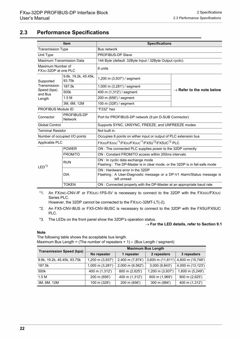
2.3 Performance Specifications
*1. An FX2NC-CNV-IF or FX3UC-1PS-5V is necessary to connect to the 32DP with the FX3GC/FX3UCSeries PLC.However, the 32DP cannot be connected to the FX3UC-32MT-LT(-2).
*2. An FX5-CNV-BUS or FX5-CNV-BUSC is necessary to connect to the 32DP with the FX5U/FX5UCPLC.
*3. The LEDs on the front panel show the 32DP’s operation status.→ For the LED details, refer to Section 9.1
NoteThe following table shows the acceptable bus length.Maximum Bus Length = (The number of repeaters + 1) × (Bus Length / segment)
Item SpecificationsTransmission Type Bus networkUnit Type PROFIBUS-DP SlaveMaximum Transmission Data 144 Byte (default: 32Byte Input / 32Byte Output cyclic)Maximum Number of FX3U-32DP at one PLC 8 units
Supported Transmission Speed (bps) and Bus Length
9.6k, 19.2k, 45.45k, 93.75k 1,200 m (3,937') / segment
→ Refer to the note below187.5k 1,000 m (3,281') / segment500k 400 m (1,312') / segment1.5 M 200 m (656') / segment3M, 6M, 12M 100 m (328') / segment
PROFIBUS Module ID “F332” hex
Connector PROFIBUS-DPNetwork Port for PROFIBUS-DP network (9 pin D-SUB Connector)
Global Control Supports SYNC, UNSYNC, FREEZE, and UNFREEZE modesTerminal Resistor Not built in.Number of occupied I/O points Occupies 8 points on either input or output of PLC extension bus
Applicable PLC FX3G/FX3GC*1/FX3U/FX3UC*1/FX5U*2/FX5UC*2 PLC
LED*3
POWER ON : The connected PLC supplies power to the 32DP correctlyFROM/TO ON : Constant FROM/TO access within 200ms intervals
RUN ON : In cyclic data exchange modeFlashing : The DP-Master is in clear mode, or the 32DP is in fail-safe mode
DIAON : Hardware error in the 32DPFlashing : A User-Diagnostic message or a DP-V1 Alarm/Status message is
left unreadTOKEN ON : Connected properly with the DP-Master at an appropriate baud rate
Transmission Speed (bps)Maximum Bus Length
No repeater 1 repeater 2 repeaters 3 repeaters9.6k, 19.2k, 45.45k, 93.75k 1,200 m (3,937') 2,400 m (7,874') 3,600 m (11,811') 4,800 m (15,748')187.5k 1,000 m (3,281') 2,000 m (6,562') 3,000 (9,843') 4,000 m (13,123')500k 400 m (1,312') 800 m (2,625') 1,200 m (3,937') 1,600 m (5,249')1.5 M 200 m (656') 400 m (1,312') 600 m (1,969') 800 m (2,625')3M, 6M, 12M 100 m (328') 200 m (656') 300 m (984') 400 m (1,312')
22

FX3U-32DP PROFIBUS-DP Interface BlockUser’s Manual
3 Installation
1
Introduction
2
Specifications
3
Installation
4
Wiring
5
Comm. Outline on PROFIBUS-DP Network
6
Buffer Mem
oryAllocation
7
Parameter Setting and Network Configuration
8
Example
Program
9
Diagnostics
3. Installation
DESIGN PRECAUTIONS
• Make sure to have the following safety circuits outside of the PLC to ensure safe system operation even duringexternal power supply problems or PLC failure.Otherwise, malfunctions may cause serious accidents.1) Most importantly, have the following: an emergency stop circuit, a protection circuit, an interlock circuit for
opposite movements (such as normal vs. reverse rotation), and an interlock circuit (to prevent damage to theequipment at the upper and lower positioning limits).
2) Note that when the PLC CPU detects an error, such as a watchdog timer error, during self-diagnosis, alloutputs are turned off. Also, when an error that cannot be detected by the PLC CPU occurs in an input/output control block, output control may be disabled.External circuits and mechanisms should be designed to ensure safe machinery operation in such a case.
3) Note that when an error occurs in a relay, triac or transistor output device, the output could be held either on or off.For output signals that may lead to serious accidents, external circuits and mechanisms should be designedto ensure safe machinery operation in such a case.
DESIGN PRECAUTIONS
• Make sure to observe the following precautions in order to prevent any damage to the machinery or accidentsdue to abnormal data written to the PLC under the influence of noise:1) Do not bundle the main circuit line together with or lay it close to the main circuit, high-voltage line, or load
line. Otherwise, noise disturbance and/or surge induction are likely to take place. As a guideline, lay thecontrol line at least 100mm (3.94") or more away from the main circuit, high-voltage line, or load line.
2) Ground the shield wire or shield of the shielded cable at one point on the PLC. However, do not ground themat the same point as the high-voltage lines.
• Install module so that excessive force will not be applied to peripheral device connectors.Failure to do so may result in wire damage/breakage or PLC failure.
INSTALLATION PRECAUTIONS
• Make sure to cut off all phases of the power supply externally before attempting installation or wiring work.Failure to do so may cause electric shock.
INSTALLATION PRECAUTIONS
• Use the product within the generic environment specifications described in the PLC main unit manual (Hardware Edition).Never use the product in areas with dust, oily smoke, conductive dusts, corrosive gas (salt air, Cl2, H2S, SO2, orNO2), flammable gas, vibration or impacts, or exposed to high temperature, condensation, or wind and rain.If the product is used in such conditions, electric shock, fire, malfunction, deterioration or damage may occur.
• Install the product securely using a DIN rail or mounting screws.• Install the product on a flat surface.
If the mounting surface is rough, undue force will be applied to the PC board, thereby causing nonconformities.• When drilling screw holes or wiring, make sure cutting or wire debris does not enter the ventilation slits.
Failure to do so may cause fire, equipment failures or malfunctions.• Be sure to remove the dust proof sheet from the PLC's ventilation port when the installation work is completed.
Failure to do so may cause fires, equipment failures, and malfunctions.• Connect the extension and communication cables securely to their designated connectors.
Unsecured connection may cause malfunctions.• Do not touch the conductive parts of the product directly to avoid failure or malfunction.
23

FX3U-32DP PROFIBUS-DP Interface BlockUser’s Manual
3 Installation3.1 Installation Arrangements
3.1 Installation Arrangements
The 32DP is connected to the extension port of an FX3G/FX3GC*1/FX3U/FX3UC*1/FX5U*2/FX5UC*2 PLC orextension unit/block (including special function unit/block) on the right side.Since additional extension devices can be added on both the left and right-hand sides of the PLC, keep anappropriate amount of space on both sides of the PLC when planning to add extension devices in the future.For further details on installation arrangements, refer to the following manual.
→ FX3G PLC Hardware Edition→ FX3GC PLC Hardware Edition
→ FX3U PLC Hardware Edition→ FX3UC PLC Hardware Edition
→ MELSEC iQ-F FX5U User's Manual (Hardware)→ MELSEC iQ-F FX5UC User's Manual (Hardware)
*1. An FX2NC-CNV-IF or FX3UC-1PS-5V is necessary to connect to the 32DP with the FX3GC/FX3UCSeries PLC.However, the 32DP cannot be connected to the FX3UC-32MT-LT(-2).
*2. An FX5-CNV-BUS or FX5-CNV-BUSC is necessary to connect to the 32DP with the FX5U/FX5UCPLC.
Note
• Keep a space of 50 mm (1.97") or more between the 32DP and the other devices and cabinet.Install the unit as far from high-voltage lines, high-voltage devices and power equipment as possible.
• To prevent the product’s temperature from rising, do not install the PLC on a floor, ceiling, or in the vertical direction. Install it horizontally on a wall as shown below.
• Take care to position the 32DP and other peripheral devices for their extension ports and cables to be as close to each other as possible.
FX3G/FX3U/FX3UC
Series main unit
FX
3U
-32
DP
≥ 50mm (1.97")
A
A
AA
A
24

FX3U-32DP PROFIBUS-DP Interface BlockUser’s Manual
3 Installation3.2 Mounting
1
Introduction
2
Specifications
3
Installation
4
Wiring
5
Comm. Outline on PROFIBUS-DP Network
6
Buffer Mem
oryAllocation
7
Parameter Setting and Network Configuration
8
Example
Program
9
Diagnostics
3.2 Mounting
The 32DP can be mounted on a DIN rail (DIN46227) or mounted directly to the mounting surface with screws.
3.2.1 Direct Mounting
The 32DP can be directly mounted with M4 screws. The 32DP mounting hole pitches are shown below. → For the connecting procedure to the extension port of the FX3G Series PLC,
refer to FX3G PLC Hardware Edition→ For the connecting procedure to the extension port of the FX3GC Series PLC,
refer to FX3GC PLC Hardware Edition→ For the connecting procedure to the extension port of the FX3U Series PLC,
refer to FX3U PLC Hardware Edition→ For the connecting procedure to the extension port of the FX3UC Series PLC,
refer to FX3UC PLC Hardware Edition→ For the connecting procedure to the extension port of the FX5U PLC,
refer to MELSEC iQ-F FX5U User's Manual (Hardware)→ For the connecting procedure to the extension port of the FX5UC PLC,
refer to MELSEC iQ-F FX5UC User's Manual (Hardware)Note
• Mounting screw: M4 screw.• An interval space between each unit of 1 to 2 mm (0.04" to 0.08") is necessary.• When connecting the 32DP to an extension unit/block (or special function unit/block), first mount the
extension unit/block (or special function unit/block) to the right side of the PLC.Direct Mounting
1) Drill screw holes on the mounting surface according to thediagram above.
2) Align the 32DP (right fig. A) with the holes and tighten withM4 screws (right fig. B).
3) Connect the 32DP’s extension cable (right fig. C) to theextension device connector of the main unit.
→ For extension cable connection procedures of the FX3GSeries PLC, refer to FX3G PLC Hardware Edition
→ For extension cable connection procedures of the FX3GCSeries PLC, refer to FX3GC PLC Hardware Edition
→ For extension cable connection procedures of the FX3USeries PLC, refer to FX3U PLC Hardware Edition
→ For extension cable connection procedures of the FX3UCSeries PLC, refer to FX3UC PLC Hardware Edition
→ For extension cable connection procedures of the FX5U PLC,refer to MELSEC iQ-F FX5U User's Manual (Hardware)
→ For extension cable connection procedures of the FX5UC PLC,refer to MELSEC iQ-F FX5UC User's Manual (Hardware)
4(0.16")
39(1.54")
80 (3
.15"
)
90 (3
.55"
)
FX3U-48MFX3U
RUN
POWER
ERROR
BATT
FX3U
ERROR
RUNBATT
POWER
0
31
2IN
OUT
64
5
217 20
24
22 23
2625
10 1113
12
16
14 1517
270
31
2
64
5
217 20
24
22 23
2625
10 1113
12
16
14 1517
27
B
A
B
25

FX3U-32DP PROFIBUS-DP Interface BlockUser’s Manual
3 Installation3.2 Mounting
3.2.2 DIN Rail Mounting
The 32DP can be mounted on a DIN rail (DIN46227, 35mm width).→ For detail, refer to FX3G PLC Hardware Edition
→ For detail, refer to FX3GC PLC Hardware Edition→ For detail, refer to FX3U PLC Hardware Edition
→ For detail, refer to FX3UC PLC Hardware Edition→ For detail, refer to MELSEC iQ-F FX5U User's Manual (Hardware)
→ For detail, refer to MELSEC iQ-F FX5UC User's Manual (Hardware)Note
• An interval space between each unit of 1 to 2 mm (0.04" to 0.08") is necessary.• When connecting the 32DP to an extension unit/block (or special function unit/block), first mount the
extension unit/block (or special function unit/block) to the right side of the PLC.DIN Rail Mounting
1) Fit the upper edge of the DIN rail mounting groove (right fig. A) onto the DINrail.
2) Push the product onto the DIN rail.
3) Connect the 32DP’s extension cable (right fig. B) to theextension device connector of the main unit.
→ For extension cable connection procedures of the FX3GSeries PLC, refer to FX3G PLC Hardware Edition
→ For extension cable connection procedures of the FX3GCSeries PLC, refer to FX3GC PLC Hardware Edition
→ For extension cable connection procedures of the FX3USeries PLC, refer to FX3U PLC Hardware Edition
→ For extension cable connection procedures of the FX3UCSeries PLC, refer to FX3UC PLC Hardware Edition
→ For extension cable connection procedures of the FX5U PLC,refer to MELSEC iQ-F FX5U User's Manual (Hardware)
→ For extension cable connection procedures of the FX5UC PLC,refer to MELSEC iQ-F FX5UC User's Manual (Hardware)
Removing from DIN Rail
1) Disconnect the PROFIBUS-DP communication cable and extension cables.2) Insert the tip of a flathead screwdriver into the hole of the DIN rail
mounting hook (right fig. A).3) Move the flathead screwdriver as shown in the figure to the right, pull
out the DIN rail mounting hook (right fig. A).4) Remove the product from the DIN rail (right fig. B).
2)
1)
A
B
A2)
4)
3)
26
FX3U-32DP PROFIBUS-DP Interface BlockUser’s Manual
4 Wiring4.1 Applicable Cable and Connector
1
Introduction
2
Specifications
3
Installation
4
Wiring
5
Comm. Outline on PROFIBUS-DP Network
6
Buffer Mem
oryAllocation
7
Parameter Setting and Network Configuration
8
Example
Program
9
Diagnostics
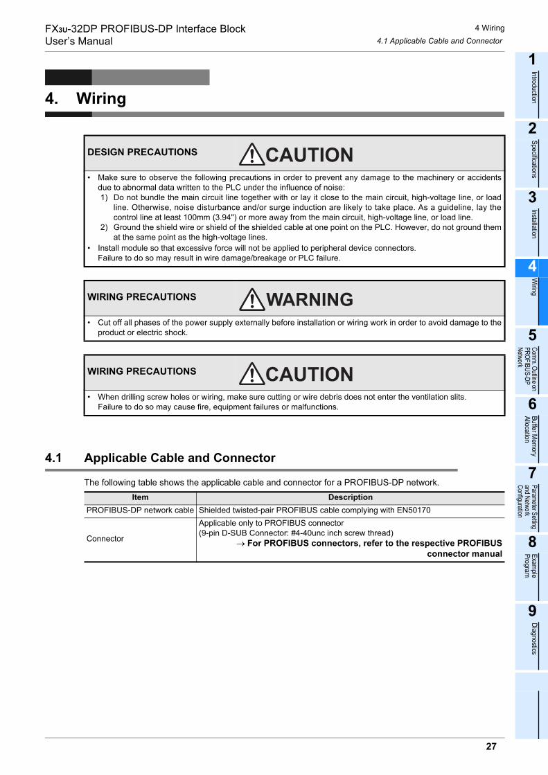
4. Wiring
4.1 Applicable Cable and Connector
The following table shows the applicable cable and connector for a PROFIBUS-DP network.
DESIGN PRECAUTIONS
• Make sure to observe the following precautions in order to prevent any damage to the machinery or accidentsdue to abnormal data written to the PLC under the influence of noise:1) Do not bundle the main circuit line together with or lay it close to the main circuit, high-voltage line, or load
line. Otherwise, noise disturbance and/or surge induction are likely to take place. As a guideline, lay thecontrol line at least 100mm (3.94") or more away from the main circuit, high-voltage line, or load line.
2) Ground the shield wire or shield of the shielded cable at one point on the PLC. However, do not ground themat the same point as the high-voltage lines.
• Install module so that excessive force will not be applied to peripheral device connectors.Failure to do so may result in wire damage/breakage or PLC failure.
WIRING PRECAUTIONS
• Cut off all phases of the power supply externally before installation or wiring work in order to avoid damage to theproduct or electric shock.
WIRING PRECAUTIONS
• When drilling screw holes or wiring, make sure cutting or wire debris does not enter the ventilation slits.Failure to do so may cause fire, equipment failures or malfunctions.
Item DescriptionPROFIBUS-DP network cable Shielded twisted-pair PROFIBUS cable complying with EN50170
Connector
Applicable only to PROFIBUS connector(9-pin D-SUB Connector: #4-40unc inch screw thread)
→ For PROFIBUS connectors, refer to the respective PROFIBUSconnector manual
27
FX3U-32DP PROFIBUS-DP Interface BlockUser’s Manual
4 Wiring4.2 PROFIBUS-DP Wiring
4.2 PROFIBUS-DP Wiring
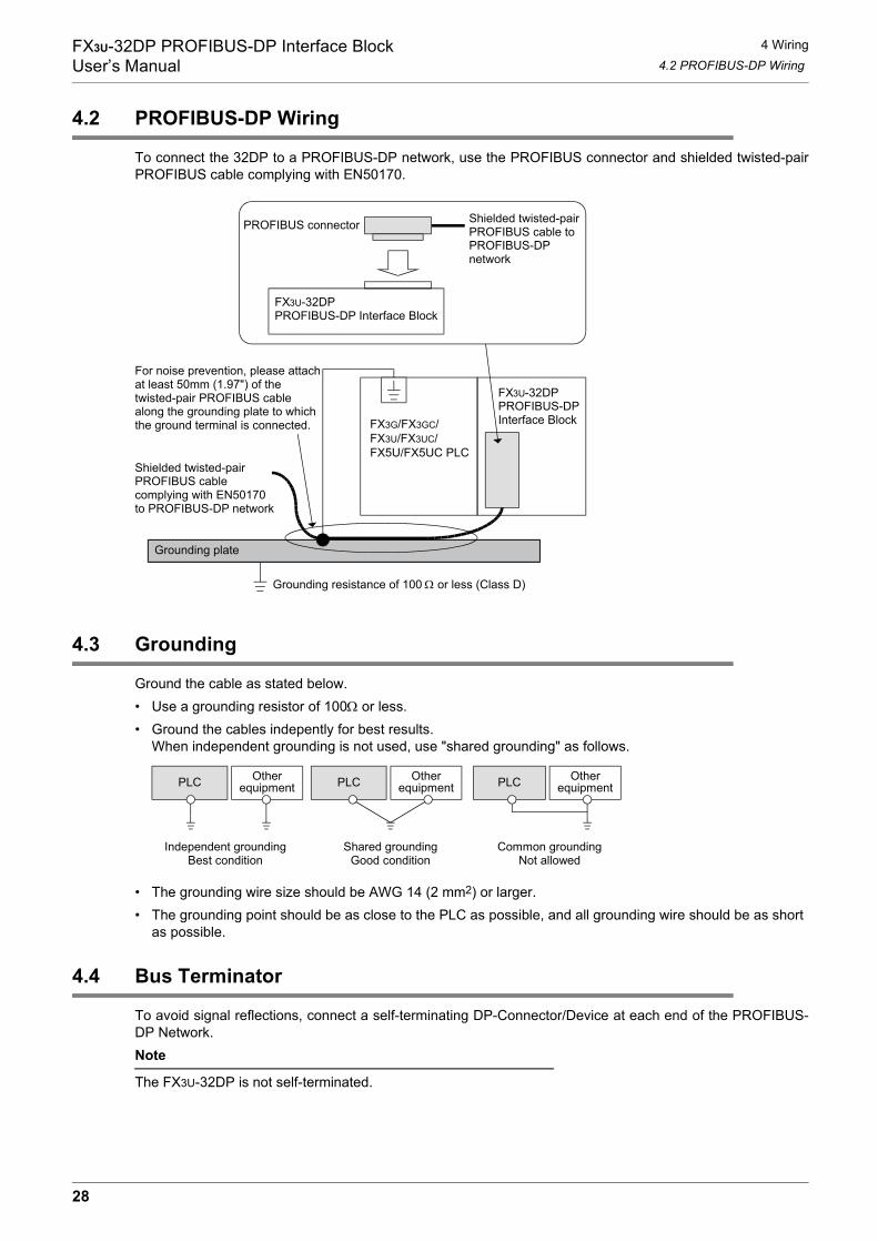
To connect the 32DP to a PROFIBUS-DP network, use the PROFIBUS connector and shielded twisted-pairPROFIBUS cable complying with EN50170.
4.3 Grounding
Ground the cable as stated below.• Use a grounding resistor of 100Ω or less.• Ground the cables indepently for best results.
When independent grounding is not used, use "shared grounding" as follows.
• The grounding wire size should be AWG 14 (2 mm2) or larger.• The grounding point should be as close to the PLC as possible, and all grounding wire should be as short
as possible.
4.4 Bus Terminator
To avoid signal reflections, connect a self-terminating DP-Connector/Device at each end of the PROFIBUS-DP Network.Note
The FX3U-32DP is not self-terminated.
Shielded twisted-pairPROFIBUS cablecomplying with EN50170to PROFIBUS-DP network
Grounding plate
Grounding resistance of 100 Ω or less (Class D)
For noise prevention, please attachat least 50mm (1.97") of thetwisted-pair PROFIBUS cablealong the grounding plate to whichthe ground terminal is connected.
Shielded twisted-pairPROFIBUS cable toPROFIBUS-DPnetwork
PROFIBUS connector
FX3U-32DPPROFIBUS-DP Interface Block
FX3U-32DPPROFIBUS-DPInterface BlockFX3G/FX3GC/
FX3U/FX3UC/FX5U/FX5UC PLC
PLC Otherequipment PLC Other
equipment PLC Otherequipment
Shared groundingGood condition
Common groundingNot allowed
Independent groundingBest condition
28
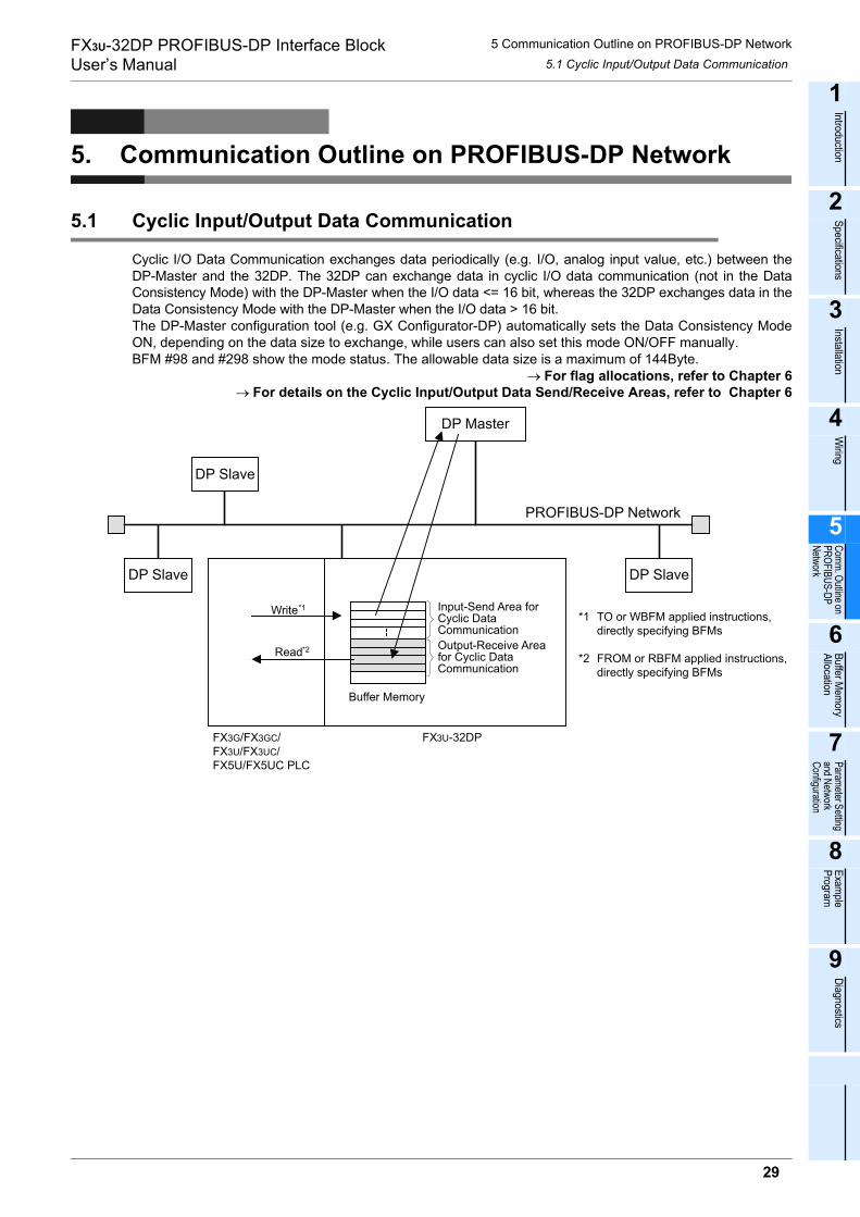
FX3U-32DP PROFIBUS-DP Interface BlockUser’s Manual
5 Communication Outline on PROFIBUS-DP Network5.1 Cyclic Input/Output Data Communication
1
Introduction
2
Specifications
3
Installation
4
Wiring
5
Comm. Outline on PROFIBUS-DP Network
6
Buffer Mem
oryAllocation
7
Parameter Setting and Network Configuration
8
Example
Program
9
Diagnostics
5. Communication Outline on PROFIBUS-DP Network
5.1 Cyclic Input/Output Data Communication
Cyclic I/O Data Communication exchanges data periodically (e.g. I/O, analog input value, etc.) between theDP-Master and the 32DP. The 32DP can exchange data in cyclic I/O data communication (not in the DataConsistency Mode) with the DP-Master when the I/O data <= 16 bit, whereas the 32DP exchanges data in theData Consistency Mode with the DP-Master when the I/O data > 16 bit.The DP-Master configuration tool (e.g. GX Configurator-DP) automatically sets the Data Consistency ModeON, depending on the data size to exchange, while users can also set this mode ON/OFF manually.BFM #98 and #298 show the mode status. The allowable data size is a maximum of 144Byte.
→ For flag allocations, refer to Chapter 6→ For details on the Cyclic Input/Output Data Send/Receive Areas, refer to Chapter 6
DP SlaveDP Slave
DP Master
PROFIBUS-DP Network
DP Slave
FX3G/FX3GC/FX3U/FX3UC/FX5U/FX5UC PLC
Input-Send Area forCyclic DataCommunicationOutput-Receive Areafor Cyclic DataCommunication
FX3U-32DP
Buffer Memory
Read*2
Write*1TO or WBFM applied instructions,directly specifying BFMs
FROM or RBFM applied instructions,directly specifying BFMs
*1
*2
29
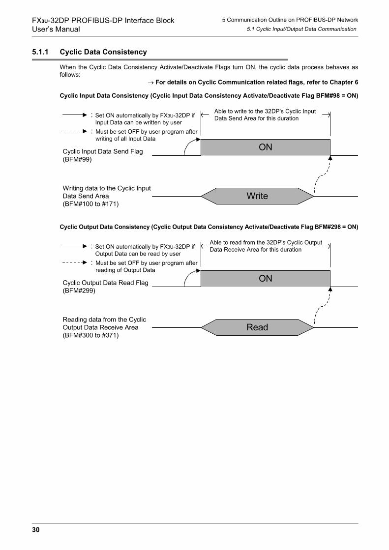
FX3U-32DP PROFIBUS-DP Interface BlockUser’s Manual
5 Communication Outline on PROFIBUS-DP Network5.1 Cyclic Input/Output Data Communication
5.1.1 Cyclic Data Consistency
When the Cyclic Data Consistency Activate/Deactivate Flags turn ON, the cyclic data process behaves asfollows:
→ For details on Cyclic Communication related flags, refer to Chapter 6
Cyclic Input Data Consistency (Cyclic Input Data Consistency Activate/Deactivate Flag BFM#98 = ON)
Cyclic Output Data Consistency (Cyclic Output Data Consistency Activate/Deactivate Flag BFM#298 = ON)
Able to write to the 32DP's Cyclic InputData Send Area for this duration
ON
Write
Cyclic Input Data Send Flag(BFM#99)
Writing data to the Cyclic InputData Send Area(BFM#100 to #171)
Set ON automatically by FX3U-32DP ifInput Data can be written by userMust be set OFF by user program afterwriting of all Input Data
:
:
Cyclic Output Data Read Flag(BFM#299)
Reading data from the CyclicOutput Data Receive Area(BFM#300 to #371)
ON
Read
Able to read from the 32DP's Cyclic OutputData Receive Area for this durationSet ON automatically by FX3U-32DP if
Output Data can be read by userMust be set OFF by user program afterreading of Output Data
:
:
30

FX3U-32DP PROFIBUS-DP Interface BlockUser’s Manual
5 Communication Outline on PROFIBUS-DP Network5.2 Acyclic Input/Output Data Communication
1
Introduction
2
Specifications
3
Installation
4
Wiring
5
Comm. Outline on PROFIBUS-DP Network
6
Buffer Mem
oryAllocation
7
Parameter Setting and Network Configuration
8
Example
Program
9
Diagnostics
5.2 Acyclic Input/Output Data Communication
Acyclic I/O data communication is available for changing DP-Slave parameters during cyclic communication.The allowable data size is a maximum of 140Byte. Cyclic Communication has a higher priority than AcyclicCommunication. Acyclic Communication is always processed in the Data Consistency Mode.
→ For flag allocations, refer to Chapter 6→ For details on Acyclic Input-Send/Output-Receive Area, refer to Chapter 6
DP SlaveDP Slave
DP Master
PROFIBUS-DP Network
DP Slave
Input-Send Area forAcyclic DataCommunicationOutput-Receive Areafor Acyclic DataCommunication
FX3U-32DP
Buffer Memory
Read*2
Write*1TO or WBFM applied instructions,directly specifying BFMs
FROM or RBFM applied instructions,directly specifying BFMs
*1
*2
FX3G/FX3GC/FX3U/FX3UC/FX5U/FX5UC PLC
31

FX3U-32DP PROFIBUS-DP Interface BlockUser’s Manual
5 Communication Outline on PROFIBUS-DP Network5.2 Acyclic Input/Output Data Communication
5.2.1 Acyclic Data Consistency
Acyclic Data Communication is always processed in the Data Consistency Mode, regardless of the BFM#98or BFM#298 settings. The 32DP supports Class 1 and 2 Acyclic Communication.
→ For details on Acyclic Communication related flags, refer to Chapter 6
Acyclic Input Data Communication
Acyclic Output Data Communication
*1. For Class 1: To prevent an "Acyclic Class 1 Response Timeout," the response time must be smallerthan 10 seconds.
For Class 2: The "Acyclic Class 2 Response Timeout" will be set by the Initiate-request(SendTimeout value) from the DP-Master.
Note : INPUT/OUTPUT to where?
When this manual references INPUT/OUTPUT for communication data on the PROFIBUS-DP network, itrefers to data from the DP-Master's point of view. Therefore, CYCLIC INPUT DATA means THE CYCLICDATA STREAMING FROM DP-SLAVE TO DP-MASTER. On the other hand, ACYCLIC OUTPUT DATA, forexample, means THE ACYCLIC DATA STREAMING FROM DP-MASTER TO DP-SLAVE.
Class1 Acyclic Input Data SendFlag (BFM#499)
Writing data to the acyclic InputData Send Area (Class1)(BFM#500 to #572)
ON
Write
Set ON automatically by FX3U-32DP ifInput Data can be written by userMust be set OFF by user programafter writing of all Input Data
:
:
Able to write to the 32DP's Acyclic InputData Send Area for this duration*1
ON
Read
Class1 Acyclic Output Data ReadFlag (BFM#699)
Reading data from the AcyclicOutput Data Receive Area (Class1)(BFM#700 to #772)
Able to read from the 32DP's Acyclic OutputData Receive Area for this duration*1Set ON automatically by FX3U-32DP if
Output Data can be read by userMust be set OFF by user programafter reading of Output Data
:
:
32

FX3U-32DP PROFIBUS-DP Interface BlockUser’s Manual
5 Communication Outline on PROFIBUS-DP Network5.3 Diagnostic Data Communication
1
Introduction
2
Specifications
3
Installation
4
Wiring
5
Comm. Outline on PROFIBUS-DP Network
6
Buffer Mem
oryAllocation
7
Parameter Setting and Network Configuration
8
Example
Program
9
Diagnostics
5.3 Diagnostic Data Communication
The 32DP classifies the diagnostic data into two categories : Alarm Message and Status Message. When the32DP’s DP-V1 functionality is ON (BFM#35 Bit0 = 1) and the Alarm/Status Switch is OFF (BFM#1299 Bit0 =0), the 32DP can send a diagnostic message as a high-prioritized Alarm Message. This Alarm Message fromthe 32DP needs to be acknowledged by the DP-Master. If this alarm-acknowledging step is not necessary,the 32DP can send a diagnostic message as a low-prioritized Status Message when users set the Alarm/Status Switch (BFM#1299 Bit0 = 1).The content of BFM#1299 Bit0 is mapped to BFM#35 Bit2.Note
If BFM#1299 Bit 0 turns to 1 when BFM#35 Bit0 = 0, BFM#38 Bit13 displays " BFM#1299 Setting Error."→ For flag allocations, refer to Chapter 6
→ For details on Slave Diagnostic Data, refer to Chapter 6
5.3.1 Diagnostic Data Communication
Diagnostic Data Communication is always processed in the Data Consistency mode, regardless of theBFM#98 setting.
→ For details on Diagnostic Data related flags, refer to Chapter 6
DP SlaveDP Slave
DP Master
PROFIBUS-DP Network
DP Slave
FX3U-32DP
Read*1
Write*2
Buffer Memory
Diagnostic/Alarm(Status) Data Area
Diagnostic/AlarmImmediate Send FlagBFM #1300
The 32DP sends Alarm Message to the DP-MasterThe DP-Master acknowledges Alarm Message
FROM or RBFM applied instructions,directly specifying BFMs
TO or WBFM applied instructions,directly specifying BFMs
*1
*2
FX3G/FX3GC/FX3U/FX3UC/FX5U/FX5UC PLC
ONDiagnostic/Alarm immediateFlag (BFM#1300)
Writing data to theDiagnostic/Alarm Data Area(BFM#1309 to #1322)
Write
Do not write to the32DP's Diagnostic/Alarm(Status) DataArea for thisduration
Must be set ON by user program
Is automatically reset after send of data
:
:
33
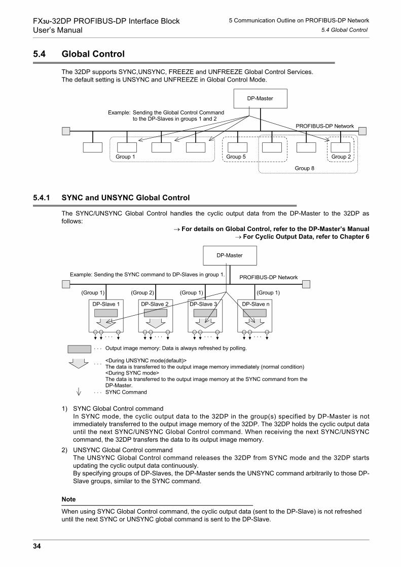
FX3U-32DP PROFIBUS-DP Interface BlockUser’s Manual
5 Communication Outline on PROFIBUS-DP Network5.4 Global Control
5.4 Global Control
The 32DP supports SYNC,UNSYNC, FREEZE and UNFREEZE Global Control Services.The default setting is UNSYNC and UNFREEZE in Global Control Mode.
5.4.1 SYNC and UNSYNC Global Control
The SYNC/UNSYNC Global Control handles the cyclic output data from the DP-Master to the 32DP asfollows:
→ For details on Global Control, refer to the DP-Master’s Manual→ For Cyclic Output Data, refer to Chapter 6
1) SYNC Global Control commandIn SYNC mode, the cyclic output data to the 32DP in the group(s) specified by DP-Master is notimmediately transferred to the output image memory of the 32DP. The 32DP holds the cyclic output datauntil the next SYNC/UNSYNC Global Control command. When receiving the next SYNC/UNSYNCcommand, the 32DP transfers the data to its output image memory.
2) UNSYNC Global Control commandThe UNSYNC Global Control command releases the 32DP from SYNC mode and the 32DP startsupdating the cyclic output data continuously.By specifying groups of DP-Slaves, the DP-Master sends the UNSYNC command arbitrarily to those DP-Slave groups, similar to the SYNC command.
Note
When using SYNC Global Control command, the cyclic output data (sent to the DP-Slave) is not refreshed until the next SYNC or UNSYNC global command is sent to the DP-Slave.
DP-Master
Group 8
Group 2Group 5Group 1
PROFIBUS-DP Network
Sending the Global Control Commandto the DP-Slaves in groups 1 and 2
Example:
(Group 1) (Group 2) (Group 1) (Group 1)
PROFIBUS-DP Network
DP-Slave 1
. . .
DP-Slave 2
. . .
DP-Slave 3
. . .
DP-Slave n
. . .
Example: Sending the SYNC command to DP-Slaves in group 1.
Output image memory: Data is always refreshed by polling.. . .
<During UNSYNC mode(default)>The data is transferred to the output image memory immediately (normal condition)<During SYNC mode>The data is transferred to the output image memory at the SYNC command from theDP-Master.
. . .
SYNC Command. . .
DP-Master
34
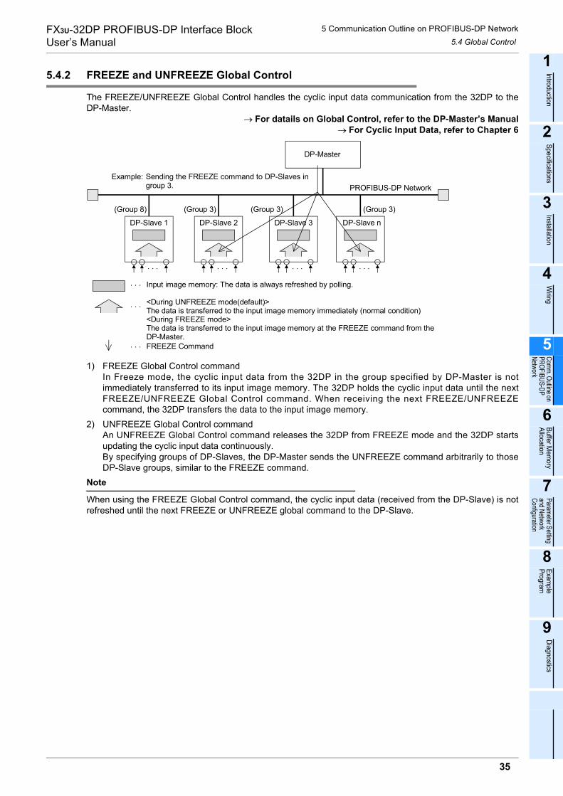
FX3U-32DP PROFIBUS-DP Interface BlockUser’s Manual
5 Communication Outline on PROFIBUS-DP Network5.4 Global Control
1
Introduction
2
Specifications
3
Installation
4
Wiring
5
Comm. Outline on PROFIBUS-DP Network
6
Buffer Mem
oryAllocation
7
Parameter Setting and Network Configuration
8
Example
Program
9
Diagnostics
5.4.2 FREEZE and UNFREEZE Global Control
The FREEZE/UNFREEZE Global Control handles the cyclic input data communication from the 32DP to theDP-Master.
→ For datails on Global Control, refer to the DP-Master’s Manual→ For Cyclic Input Data, refer to Chapter 6
1) FREEZE Global Control commandIn Freeze mode, the cyclic input data from the 32DP in the group specified by DP-Master is notimmediately transferred to its input image memory. The 32DP holds the cyclic input data until the nextFREEZE/UNFREEZE Global Control command. When receiving the next FREEZE/UNFREEZEcommand, the 32DP transfers the data to the input image memory.
2) UNFREEZE Global Control commandAn UNFREEZE Global Control command releases the 32DP from FREEZE mode and the 32DP startsupdating the cyclic input data continuously.By specifying groups of DP-Slaves, the DP-Master sends the UNFREEZE command arbitrarily to thoseDP-Slave groups, similar to the FREEZE command.
Note
When using the FREEZE Global Control command, the cyclic input data (received from the DP-Slave) is notrefreshed until the next FREEZE or UNFREEZE global command to the DP-Slave.
(Group 8) (Group 3) (Group 3) (Group 3)
PROFIBUS-DP Network
DP-Slave 1
. . .
DP-Slave 2
. . .
DP-Slave 3
. . .
DP-Slave n
. . .
Input image memory: The data is always refreshed by polling.. . .
<During UNFREEZE mode(default)>The data is transferred to the input image memory immediately (normal condition)<During FREEZE mode>The data is transferred to the input image memory at the FREEZE command from theDP-Master.
. . .
FREEZE Command. . .
Example: Sending the FREEZE command to DP-Slaves in group 3.
DP-Master
35
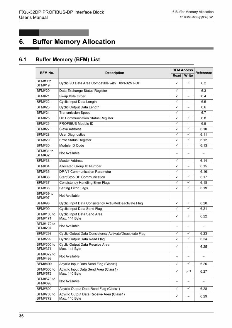
FX3U-32DP PROFIBUS-DP Interface BlockUser’s Manual
6 Buffer Memory Allocation6.1 Buffer Memory (BFM) List
6. Buffer Memory Allocation
6.1 Buffer Memory (BFM) List
BFM No. DescriptionBFM Access
ReferenceRead Write
BFM#0 toBFM#19 Cyclic I/O Data Area Compatible with FX0N-32NT-DP 6.2
BFM#20 Data Exchange Status Register − 6.3BFM#21 Swap Byte Order − 6.4BFM#22 Cyclic Input Data Length − 6.5BFM#23 Cyclic Output Data Length − 6.6BFM#24 Transmission Speed − 6.7BFM#25 DP Communication Status Register 6.8BFM#26 PROFIBUS Module ID − 6.9BFM#27 Slave Address 6.10BFM#28 User Diagnostics 6.11BFM#29 Error Status Register 6.12BFM#30 Module ID Code − 6.13BFM#31 toBFM#32 Not Available − − −
BFM#33 Master Address − 6.14BFM#34 Allocated Group ID Number − 6.15BFM#35 DP-V1 Communication Parameter − 6.16BFM#36 Start/Stop DP Communication 6.17BFM#37 Consistency Handling Error Flags 6.18BFM#38 Setting Error Flags 6.19BFM#39 toBFM#97 Not Available
BFM#98 Cyclic Input Data Consistency Activate/Deactivate Flag 6.20BFM#99 Cyclic Input Data Send Flag 6.21BFM#100 toBFM#171
Cyclic Input Data Send AreaMax. 144 Byte 6.22
BFM#172 toBFM#297 Not Available − − −
BFM#298 Cyclic Output Data Consistency Activate/Deactivate Flag 6.23BFM#299 Cyclic Output Data Read Flag 6.24BFM#300 toBFM#371
Cyclic Output Data Receive AreaMax. 144 Byte − 6.25
BFM#372 toBFM#498 Not Available − − −
BEM#499 Acyclic Input Data Send Flag (Class1) 6.26BFM#500 toBFM#572
Acyclic Input Data Send Area (Class1)Max. 140 Byte
*1 6.27
BFM#573 toBFM#698 Not Available − − −
BFM#699 Acyclic Output Data Read Flag (Class1) 6.28BFM#700 toBFM#772
Acyclic Output Data Receive Area (Class1)Max. 140 Byte − 6.29
36

FX3U-32DP PROFIBUS-DP Interface BlockUser’s Manual
6 Buffer Memory Allocation6.2 Cyclic I/O Data Area Compatible with FX0N-32NT-DP [BFM #0 to BFM #19]
1
Introduction
2
Specifications
3
Installation
4
Wiring
5
Comm. Outline on PROFIBUS-DP Network
6
Buffer Mem
oryAllocation
7
Parameter Setting and Network Configuration
8
Example
Program
9
Diagnostics
*1. BFM#500 to 502 are Read Only.*2. BFM#900 to 902 are Read Only.*3. BFM#1301 to 1308 are Read Only.
Note
• Do not access the "Not Available" BFMs with FROM/TO instructions. Accessing BFMs that are not available may cause operation errors in the 32DP.
• Do not write to the "Read Only" BFMs with TO instructions.INPUT/OUTPUT to where?
When this manual references INPUT/OUTPUT for communication data on the PROFIBUS-DP network, it refers to data from the DP-Master's point of view. Therefore, CYCLIC INPUT DATA means THE CYCLIC DATA STREAMING FROM DP-SLAVE TO DP-MASTER. On the other hand, ACYCLIC OUTPUT DATA, for example, means THE ACYCLIC DATA STREAMING FROM DP-MASTER TO DP-SLAVE.
6.2 Cyclic I/O Data Area Compatible with FX0N-32NT-DP [BFM #0 to BFM #19]
BFM Access : Read / WriteThe 32DP allocates Byte1 - 40 of Cyclic Output Data by the FROM instruction to the Cyclic Output Data Receive Area (BFM#300 to #371), while it allocates Byte1 - 40 of Cyclic Input Data by the TO instruction to the Cyclic Input Data Send Area (BFM#100 to #171).*1
*1. These redundant allocations are implemented for compatibility to the FX0N-32NT-DP. Regardless ofthe data amount, it is recommended for most users to refer to the Cyclic Input/Output Data Receive/Send Area (BFM#100 to #171/BFM#300 to 371).
BFM#773 toBFM#898 Not Available − − −
BFM#899 Acyclic Input Data Send Flag (Class2) 6.30BFM#900 toBFM#972
Acyclic Input Data Send Area (Class2)Max. 140 Byte
*2 6.31
BFM#973 toBFM#1098 Not Available − − −
BFM#1099 Acyclic Output Data Read Flag (Class2) 6.32BFM#1100 toBFM#1172
Acyclic Output Data Receive Area (Class2)Max. 140 Byte − 6.33
BFM#1173 toBFM#1297 Not Available − − −
BFM#1298 Reset Extended Diagnostic/Alarm Data Area Flag 6.34BFM#1299 Alarm/Status Switch 6.35BFM#1300 Diagnostic/Alarm Immediate Send Flag 6.36BFM#1301 toBFM#1325 Diagnostic/Alarm(Status) Data Area *3 6.37
BFM No. DescriptionBFM Access
ReferenceRead Write
FROM Instruction AccessBFM Content
TO Instruction AccessBFM Content
Writing to BFM #100Writing to BFM #101
Writing to BFM #119
BFM #0 #1
#19
Copied from BFM #300Copied form BFM #301
Copied from BFM #319
BFM #0#1
#19
37

FX3U-32DP PROFIBUS-DP Interface BlockUser’s Manual
6 Buffer Memory Allocation6.3 Data Exchange Status Register [BFM #20]
6.3 Data Exchange Status Register [BFM #20]
BFM Access : Read OnlyThis BFM shows the data exchange status.
The following values show the PROFIBUS-DP communication status.
6.4 Swap Byte Order [BFM #21 Bit0 and Bit1]
BFM Access : Read OnlyThis BFM determines the byte-order swap for the I/O data and diagnostic data.*1
*1. The 32DP does not swap the I&M data byte-order, therefore the I&M data byte-order is always thehigh-byte followed by the low-byte.
Note
The Swap Byte Order can be set up by the DP-Master Configuration Tool. When using GX Configurator-DP, the Swap Byte Order is specified in the Extended User Parameters for the Slave.
→ For details, refer to Subsection 7.1.2
6.5 Cyclic Input Data Length [BFM #22]
BFM Access : Read OnlyThis BFM shows the cyclic input data length. The valid range lies from 0 to 72 words. When the value is out ofthe range, The 32DP writes "0xFF" to this BFM.
6.6 Cyclic Output Data Length [BFM #23]
BFM Access : Read OnlyThis BFM shows the cyclic output data length. The valid range lies from 0 to 72 words. When the value is outof the range, The 32DP writes "0xFF" to this BFM.
Bit No. Name DescriptionBit 0 Data Exchange Bit ON when the 32DP is in the Data Exchange ModeBit1 Clear/Fail-Safe State ON when the 32DP is in the Clear/Fail-Safe statusBit2 to Bit15 Not Available −
Value Description
K0The 32DP is in STOP/OFFLINE modeBFM25 Bit0 is " 0 " when the 32DP established no communication, the 32DP is OFFLINEBFM25 Bit0 is " 1 " when the 32DP established a communication, the 32DP is ONLINE
K1 The 32DP is in RUN modeK3 The 32DP is in Clear/Fail-Safe mode
Bit No. Name Description
Bit 0 Cyclic Data Swap Byte Order When turning this bit ON, the 32DP swaps the low and high byteof cyclic I/O data and diagnostic (alarm) messages
Bit1 Acyclic Data Swap Byte Order When turning this bit ON, the 32DP swaps the low and high byteof acyclic I/O data
Bit2 to 15 Not Available −
38
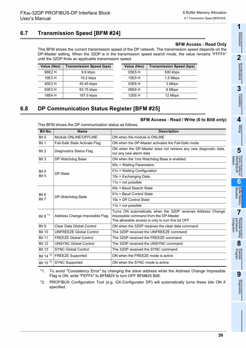
FX3U-32DP PROFIBUS-DP Interface BlockUser’s Manual
6 Buffer Memory Allocation6.7 Transmission Speed [BFM #24]
1
Introduction
2
Specifications
3
Installation
4
Wiring
5
Comm. Outline on PROFIBUS-DP Network
6
Buffer Mem
oryAllocation
7
Parameter Setting and Network Configuration
8
Example
Program
9
Diagnostics
6.7 Transmission Speed [BFM #24]
BFM Access : Read OnlyThis BFM shows the current transmission speed of the DP network. The transmission speed depends on theDP-Master setting. When the 32DP is in the transmission speed search mode, the value remains "FFFFh"until the 32DP finds an applicable transmission speed.
6.8 DP Communication Status Register [BFM #25]
BFM Access : Read / Write (0 to Bit8 only)This BFM shows the DP communication status as follows.
*1. To avoid "Consistency Error" by changing the slave address while the Address Change ImpossibleFlag is ON, write "FEFFh" to BFM#25 to turn OFF BFM#25 Bit8.
*2. PROFIBUS Configuration Tool (e.g. GX-Configurator DP) will automatically turns these bits ON ifspecified.
Value (Hex) Transmission Speed (bps) Value (Hex) Transmission Speed (bps)96E2 H 9.6 kbps 05E5 H 500 kbps19E3 H 19.2 kbps 15E5 H 1.5 Mbps45E3 H 45.45 kbps 03E6 H 3 Mbps93E3 H 93.75 kbps 06E6 H 6 Mbps18E4 H 187.5 kbps 12E6 H 12 Mbps
Bit No. Name DescriptionBit 0 Module ONLINE/OFFLINE ON when the module is ONLINEBit 1 Fail-Safe State Activate Flag ON when the DP-Master activates the Fail-Safe mode
Bit 2 Diagnostics Status Flag ON when the DP-Master does not retrieve any new diagnostic data,nor any new alarm data
Bit 3 DP Watchdog Base ON when the 1ms Watchdog Base is enabled
Bit 4Bit 5 DP-State
00b = Waiting Parameters01b = Waiting Configuration10b = Exchanging Data11b = not possible
Bit 6Bit 7 DP-Watchdog-State
00b = Baud Search State01b = Baud Control State10b = DP Control State11b = not possible
Bit 8 *1 Address Change Impossible FlagTurns ON automatically when the 32DP receives Address ChangeImpossible command from the DP-MasterThe allowable access is only to turn this bit OFF
Bit 9 Clear Data Global Control ON when the 32DP receives the clear data commandBit 10 UNFREEZE Global Control The 32DP received the UNFREEZE commandBit 11 FREEZE Global Control The 32DP received the FREEZE commandBit 12 UNSYNC Global Control The 32DP received the UNSYNC commandBit 13 SYNC Global Control The 32DP received the SYNC command
Bit 14 *2 FREEZE Supported ON when the FREEZE mode is active
Bit 15 *2 SYNC Supported ON when the SYNC mode is active
39

FX3U-32DP PROFIBUS-DP Interface BlockUser’s Manual
6 Buffer Memory Allocation6.9 PROFIBUS Module ID [BFM #26]
6.9 PROFIBUS Module ID [BFM #26]
BFM Access : Read OnlyThis BFM shows the ID code that the PROFIBUS User Organization (PNO) has issued to the 32DP : F332h.
6.10 Slave Address [BFM #27]
BFM Access : Read / WriteThis BFM shows the actual slave address. When changing the slave address with a TO instruction, usersmust write the new address value (0 - 126d) to this BFM, while verifying that the configured DP address willmatch the projected DP address. When the slave address is changed more than once in 5 seconds, the "Consistency Error" (BFM#29 Bit5) and"Change Slave Address EEPROM Error" (BFM#37 Bit10) appear, and the 32DP latches the latest validaddress. For changing the slave address via SSA-telegram, the valid address setting range is (0 to 125d).When the new address value is outside the range (0 to 126d), a "Slave Address Change Error" appears, andthe 32DP latches the latest valid address. The slave address can only be changed when the slave is in STOPmode (BFM#20 Bit0 = OFF) with the "Address Change Impossible Flag" set to OFF (BFM#25 Bit8). When theuser changes the slave address with the "Address Change Impossible Flag" set to ON (BFM#25 Bit8), the"Consistency Error" (BFM#29 Bit5) and "Change Slave Address EEPROM Error" (BFM#37 Bit10) appear.
→ For details on the Address Change Impossible Flag, refer to Section 6.8
6.11 User Diagnostics [BFM #28]
BFM Access : Read / WriteBy writing to this BFM, the 32DP can send user-diagnostic data with high priority to the DP-Master. The datafrom this BFM is handled as the extended diagnostic data by the DP-Master. When using this functionality,users need to define the meaning for each bit. This functionality is compatible to the FX0N-32NT-DP. The32DP maps this BFM to BFM#1307.
→ For the details on other diagnostic data, refer to Section 6.37
40

FX3U-32DP PROFIBUS-DP Interface BlockUser’s Manual
6 Buffer Memory Allocation6.12 Error Status Register [BFM #29 Bit0 to Bit13]
1
Introduction
2
Specifications
3
Installation
4
Wiring
5
Comm. Outline on PROFIBUS-DP Network
6
Buffer Mem
oryAllocation
7
Parameter Setting and Network Configuration
8
Example
Program
9
Diagnostics
6.12 Error Status Register [BFM #29 Bit0 to Bit13]
BFM Access : Read / WriteThis BFM shows the 32DP’s error status. In the General Error (BFM#29 Bit0 = ON), the 32DP sends the datafrom BFM#28 and #29 as diagnostic data to the DP-Master, while suspending the normal data exchange.When turning the PLC from STOP to RUN, all BFM#29 Bits turn OFF except Bit3, 4, 12 and 13.The 32DP maps this BFM to BFM#1308.
*1. BFM#37 shows the error reason.→ For details on BFM#37, refer to Section 6.18
*2. BFM#38 shows the error reason.→ For details on BFM#38, refer to Section 6.19
*3. BFM#35 shows the error reason.→ For details on BFM#35, refer to Section 6.16
*4. BFM#27 includes additional information.→ For details on BFM#27, refer to Section 6.10
6.13 Module ID Code [BFM #30]
BFM Access : Read OnlyThis BFM shows " 7150 " as the Module ID Code of the 32DP, given by its vendor.
6.14 Master Address [BFM #33]
BFM Access : Read OnlyThis BFM shows the DP-Master address on the DP network, where the 32DP exists. When the DP-Masterdoes not recognize the 32DP, this BFM value is 00FFh.
Bit No. Name DescriptionBit 0 General Error ON when any one or more of BFM#29’s Bit1, 8 to 13 is ON
Bit 1 PLC in STOP mode ON when the connected PLC is in STOP mode, and turns OFFwhen the PLC switches into RUN
Bit 2 Extended-user Alarm/Diagnostic Data Not Yet Sent Flag ON when BFM#25 Bit2 is not 0
Bit 3 Hardware Error ON when the 32DP detects an internal hardware errorBit 4 EEPROM Error ON when the slave address data in the EEPROM is corrupt
Bit 5 Consistency Handling Error Flags ON when the 32DP detects a consistency error *1
Bit 6 Setting Error Flag ON when the 32DP detects an incorrect BFM setting *2
Bit 7 Not Available −
Bit 8 Watchdog DP Timeout ON when the 32DP detects no reply from the DP-Master within thepreset watchdog time
Bit 9 Acyclic Communication Error ON when an error occurs in acyclic communication *3
Bit 10 Configuration Error ON when the 32DP receives incorrect Config DataBit 11 Parameter Error ON when the 32DP receives incorrect Parameter Data
Bit 12 Slave Address Change ErrorON when the 32DP detects an incorrect address or the addressoutside the range : 0 to 126*4
Bit 13 Slave "Reset No AddressChange" Error
ON when the 32DP detects an error due to resetting the AddressChange Impossible Flag (BFM#25 Bit8)" in Data Exchange mode,or resetting this flag while the access to BFM#25 Bit8 is disabled
Bit 14 to 15 Not Available −
41

FX3U-32DP PROFIBUS-DP Interface BlockUser’s Manual
6 Buffer Memory Allocation6.15 Allocated Group ID Number [BFM #34]
6.15 Allocated Group ID Number [BFM #34]
BFM Access : Read OnlyThis BFM shows the groups including the 32DP.
The DP-Master can allocate the 32DP to two or more groups simultaneously. When the BFM#34 = 0, the DP-Master has not allocated the 32DP to any group.
6.16 DP-V1 Communication Parameter [BFM #35]
BFM Access : Read OnlyThis BFM shows the 32DP’s communication status. Depending on the module status, this BFM content variesas follows.
*1. BFM#35 Bit2 corresponds to BFM#1299 Bit0.→ For details on BFM#1299, refer to Section 6.35
*2. If any of these bits is ON, the 32DP aborts the acyclic service and sends the corresponding error tothe DP-Master.
Bit No. Name DescriptionBit 0 Allocated Group 1 On when the 32DP belongs to Group 1Bit 1 Allocated Group 2 On when the 32DP belongs to Group 2Bit 2 Allocated Group 3 On when the 32DP belongs to Group 3Bit 3 Allocated Group 4 On when the 32DP belongs to Group 4Bit 4 Allocated Group 5 On when the 32DP belongs to Group 5Bit 5 Allocated Group 6 On when the 32DP belongs to Group 6Bit 6 Allocated Group 7 On when the 32DP belongs to Group 7Bit 7 Allocated Group 8 On when the 32DP belongs to Group 8Bit 8 to 15 Not Available −
Bit No. Name DescriptionBit 0 DP-V1 acyclic service enabled ON when the DP-V1 service is enabledBit 1 Not Available −
Bit 2 Alarm/Status Switch Status *1 Same status as BFM#1299 Bit0
Bit 3 to 7 Not Available −
Bit 8 *2 Class1 General Service ErrorON when BFM#35 Bit9 or Bit10 is ONON when an error occurs during the ALARM processingON when an error occurs in the Class1 Transmission Delay
Bit 9 *2 Class1 Read Error ON when an error occurs during the acyclic Class1 read service
Bit 10 *2 Class1 Write Error ON when an error occurs during the acyclic Class1 write service
Bit 11 Not Available −
Bit 12 *2 Class2 General ErrorON when BFM#35 Bit13, Bit14 or Bit15 is ONON when an error occurs in Class2 transmission delay
Bit 13 *2 Class2 Read Error ON when an error occurs during the acyclic Class2 read service
Bit 14 *2 Class2 Write Error ON when an error occurs during the acyclic Class2 write service
Bit 15 *2 Class2 Transport Error ON when an error occurs during the acyclic Class2 transport serviceON when an error occurs in the Class2 transmission delay
42
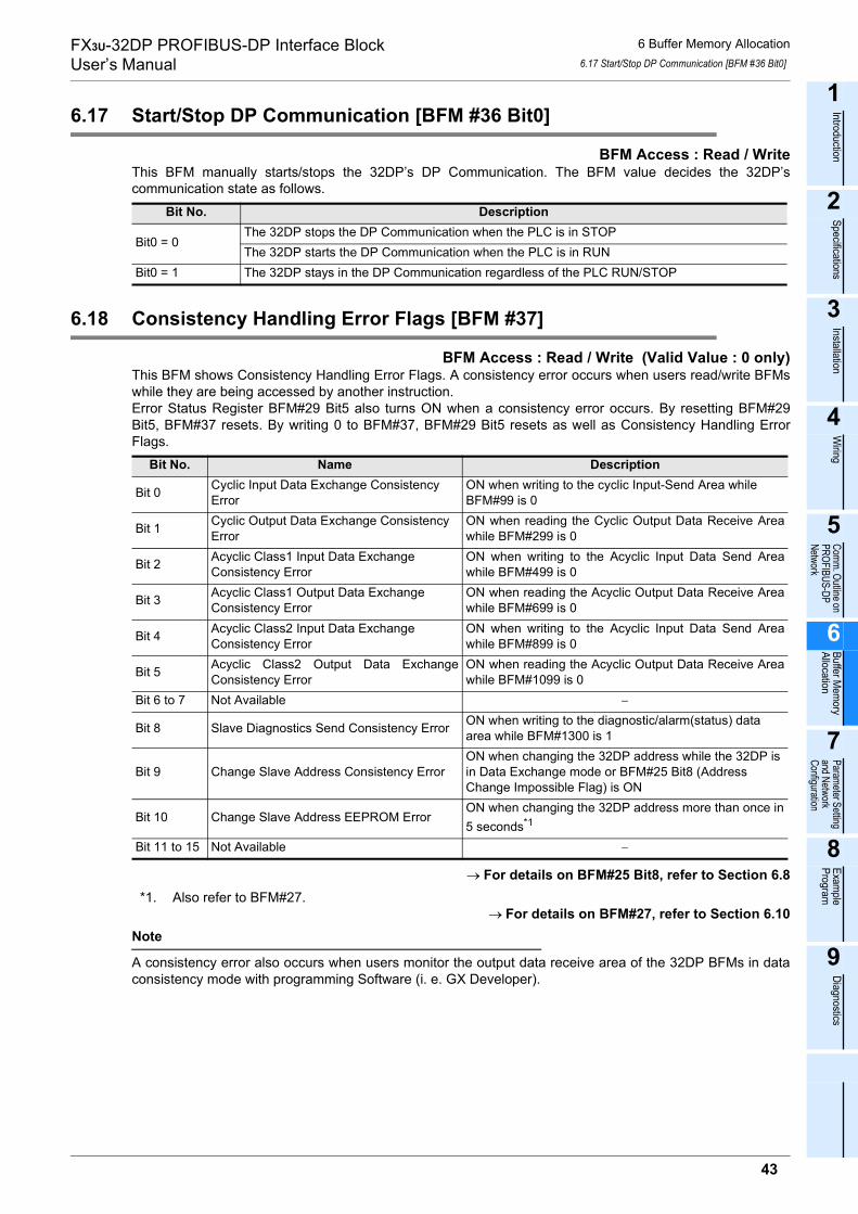
FX3U-32DP PROFIBUS-DP Interface BlockUser’s Manual
6 Buffer Memory Allocation6.17 Start/Stop DP Communication [BFM #36 Bit0]
1
Introduction
2
Specifications
3
Installation
4
Wiring
5
Comm. Outline on PROFIBUS-DP Network
6
Buffer Mem
oryAllocation
7
Parameter Setting and Network Configuration
8
Example
Program
9
Diagnostics
6.17 Start/Stop DP Communication [BFM #36 Bit0]
BFM Access : Read / WriteThis BFM manually starts/stops the 32DP’s DP Communication. The BFM value decides the 32DP’scommunication state as follows.
6.18 Consistency Handling Error Flags [BFM #37]
BFM Access : Read / Write (Valid Value : 0 only)This BFM shows Consistency Handling Error Flags. A consistency error occurs when users read/write BFMswhile they are being accessed by another instruction.Error Status Register BFM#29 Bit5 also turns ON when a consistency error occurs. By resetting BFM#29Bit5, BFM#37 resets. By writing 0 to BFM#37, BFM#29 Bit5 resets as well as Consistency Handling ErrorFlags.
→ For details on BFM#25 Bit8, refer to Section 6.8*1. Also refer to BFM#27.
→ For details on BFM#27, refer to Section 6.10Note
A consistency error also occurs when users monitor the output data receive area of the 32DP BFMs in dataconsistency mode with programming Software (i. e. GX Developer).
Bit No. Description
Bit0 = 0The 32DP stops the DP Communication when the PLC is in STOPThe 32DP starts the DP Communication when the PLC is in RUN
Bit0 = 1 The 32DP stays in the DP Communication regardless of the PLC RUN/STOP
Bit No. Name Description
Bit 0 Cyclic Input Data Exchange ConsistencyError
ON when writing to the cyclic Input-Send Area whileBFM#99 is 0
Bit 1 Cyclic Output Data Exchange ConsistencyError
ON when reading the Cyclic Output Data Receive Areawhile BFM#299 is 0
Bit 2 Acyclic Class1 Input Data ExchangeConsistency Error
ON when writing to the Acyclic Input Data Send Areawhile BFM#499 is 0
Bit 3 Acyclic Class1 Output Data ExchangeConsistency Error
ON when reading the Acyclic Output Data Receive Areawhile BFM#699 is 0
Bit 4 Acyclic Class2 Input Data ExchangeConsistency Error
ON when writing to the Acyclic Input Data Send Areawhile BFM#899 is 0
Bit 5 Acyclic Class2 Output Data ExchangeConsistency Error
ON when reading the Acyclic Output Data Receive Areawhile BFM#1099 is 0
Bit 6 to 7 Not Available −
Bit 8 Slave Diagnostics Send Consistency Error ON when writing to the diagnostic/alarm(status) dataarea while BFM#1300 is 1
Bit 9 Change Slave Address Consistency ErrorON when changing the 32DP address while the 32DP isin Data Exchange mode or BFM#25 Bit8 (AddressChange Impossible Flag) is ON
Bit 10 Change Slave Address EEPROM ErrorON when changing the 32DP address more than once in5 seconds*1
Bit 11 to 15 Not Available −
43

FX3U-32DP PROFIBUS-DP Interface BlockUser’s Manual
6 Buffer Memory Allocation6.19 Setting Error Flag [BFM #38]
6.19 Setting Error Flag [BFM #38]
BFM Access : Read / Write (Valid Value : 0 bitwise)This BFM shows the setting error reasons. This BFM corresponds to BFM#29 Bit6. By resetting BFM#29 Bit6,BFM#38 also resets. By writing 0 to each bit in BFM#38, each flag resets individually.
*1. If writing "0" to BFM#1298 when the 32DP is not in data exchange mode, the 32DP keeps BFM#1309- #1322 contents, whereas the 32DP clears them at the next mode switch into data exchange mode.
→ For details on BFM#36, refer to Section 6.17→ For details on BFM#99, refer to Section 6.21
→ For details on BFM#299, refer to Section 6.24→ For details on BFM#499, refer to Section 6.26→ For details on BFM#699, refer to Section 6.28→ For details on BFM#899, refer to Section 6.30
→ For details on BFM#1099, refer to Section 6.32→ For details on BFM#98, refer to Section 6.20
→ For details on BFM#298, refer to Section 6.23→ For details on BFM#1298, refer to Section 6.34→ For details on BFM#1299, refer to Section 6.35→ For details on BFM#1300, refer to Section 6.36
Bit No. DescriptionBit 0 ON when writing to " Not Available " or " Read Only " BFMs
Bit 1 ON when writing an incorrect value to [BFM#36 Start/Stop DP-Communication](Valid write value for BFM#36: 0 or 1)
Bit 2 Not AvailableBit 3 Not Available
Bit 4 ON when writing an incorrect value to [BFM#99 Cyclic Input Data Send Flag](Valid write value for BFM#99: 0 only)
Bit 5 ON when writing an incorrect value to [BFM#299 Cyclic Output Data Read Flag](Valid write value for BFM#299: 0 only)
Bit 6 ON when writing an incorrect value to [BFM#499 Acyclic Input Data Send Flag(Class1)](Valid write value for BFM#499: 0 only)
Bit 7 ON when writing an incorrect value to [BFM#699 Acyclic Output Data Read Flag(Class1)](Valid write value for BFM#699: 0 only)
Bit 8 ON when writing an incorrect value to [BFM#899 Acyclic Input Data Send Flag(Class2)](Valid write value for BFM#899: 0 only)
Bit 9 ON when writing an incorrect value to [BFM#1099 Acyclic Output Data Read Flag(Class1)](Valid write value for BFM#1099: 0 only)
Bit 10 ON when writing an incorrect value to [BFM#98 Cyclic Input Data Consistency Activate/Deactivate Flag](Valid write value for BFM#98: 0 or 1)
Bit 11 ON when writing an incorrect value to [BFM#298 Cyclic Output Data Consistency Activate/Deactivate Flag](Valid write value for BFM#298: 0 or 1)
Bit 12 *1
ON when writing an incorrect value to [BFM#1298 Reset Extended User-Diagnostic/Alarm Data Area Flag](Valid write value for BFM#1298: 0 only)ON when writing "0" to BFM#1298 before the DP-Master acknowledges all the Alarm MessagesON when writing "0" to BFM#1298 while BFM#1298 is "0"ON when writing "0" to BFM#1298 while BFM#1309 to #1322 are already "0"
Bit 13
ON when writing an incorrect value to [BFM#1299 Alarm/Status Switch](Valid write value for BFM#1299: 0 or 1)ON when BFM#1299 turns ON while BFM#35 Bit0 = 0 (DP-V1 disabled)ON when the DP-Master does not recognize the Alarm(Status) Message from the 32DPON when the DIA LED is ON (Any value in BFM#28, #29, #1298 and #1300 is not "0")ON when a process error occurs in sending a User-Diagnostic/Alarm(Status) Message
Bit 14 ON when writing an incorrect value to [BFM#1300 Diagnostic/Alarm Immediate Send Flag](Valid write value for BFM#1300: 1 only)
Bit 15 ON when writing an incorrect value to [BFM#25 DP Communication Status Register](Valid write value for BFM#25: FEFFh only)
44

FX3U-32DP PROFIBUS-DP Interface BlockUser’s Manual
6 Buffer Memory Allocation6.20 Cyclic Input Data Consistency Activate/Deactivate Flag [BFM #98 Bit0]
1
Introduction
2
Specifications
3
Installation
4
Wiring
5
Comm. Outline on PROFIBUS-DP Network
6
Buffer Mem
oryAllocation
7
Parameter Setting and Network Configuration
8
Example
Program
9
Diagnostics
6.20 Cyclic Input Data Consistency Activate/Deactivate Flag [BFM #98 Bit0]
BFM Access : Read / WriteBFM#98 Bit0 turns ON when the DP communication requires data consistency for communication data>16bit/block. The PROFIBUS Configuration Tool (e.g. GX-Configurator DP) automatically turns this bit ON.Users can set/reset this bit manually as well, for example, by PLC program.Acyclic data communication will always set the data consistency mode, regardless of this flag’s setting.
→ For details on Cyclic Communication, refer to Section 5.1→ For details on the data consistency mode, refer to Section 5.1
6.21 Cyclic Input Data Send Flag [BFM #99 Bit0]
BFM Access : Read / WriteThe 32DP turns this flag ON automatically when new data can be written to the Cyclic Input Data Send Area.After the writing process is finished, the user must turn this flag OFF.
→ For details on the data consistency mode, refer to Section 5.1
6.22 Cyclic Input Data Send Area [BFM #100 to #171]
BFM Access : Read / WriteThis is the data storage area for cyclic input data, bound to be transferred to the DP-Master. A maximum of144 Bytes of cyclic input data can be stored.
→ For details on Cyclic Communication, refer to Section 5.1Note
When the connected PLC is in STOP, the 32DP maintains no cyclic input data. It is necessary to prepare an appropriate amount of initial data in the send buffer before the 32DP initializes the cyclic communication.
6.23 Cyclic Output Data Consistency Activate/Deactivate Flag[BFM #298 Bit0]
BFM Access : Read / WriteBFM#298 Bit0 turns ON when the DP communication requires the data consistency. When a user sets thedata consistency mode for one or more I/O modules for the 32DP, and when the communication databetween those I/O modules and the 32DP>16bit/block, the user’s configuration will turn this bit ONautomatically. Users can set/reset this bit manually as well.
→ For details on the data consistency mode, refer to Section 5.1
6.24 Cyclic Output Data Read Flag [BFM #299 Bit0]
BFM Access : Read / WriteThe 32DP turns this flag ON automatically when new cyclic output data is available in the Cyclic Output DataReceive Area. After reading the data, the user must turn this flag OFF.
→ For details on the data consistency mode, refer to Section 5.1
Bit 0Upper byte Lower byteBFM Address
BFM #100#101#102#103
2nd byte 1st byte4th byte 3rd byte6th byte 5th byte8th byte 7th byte
40th byte 39th byte#119#120 42nd byte 41st byte
144th byte 143rd byte#171
Copied to BFM #0 to #19(TO instruction access)
45

FX3U-32DP PROFIBUS-DP Interface BlockUser’s Manual
6 Buffer Memory Allocation6.25 Cyclic Output Data Receive Area [BFM #300 to #371]
6.25 Cyclic Output Data Receive Area [BFM #300 to #371]
BFM Access : Read OnlyThis is the data storage area for cyclic output data from the DP-Master. A maximum of 144 Bytes of cyclicoutput data can be stored.
→ For details on Cyclic Communication, refer to Section 5.1
6.26 Acyclic Input Data Send Flag (Class1) [BFM #499 Bit0]
BFM Access : Read / WriteThe 32DP turns this flag ON automatically when new acyclic input data can be written to the Acyclic InputData Send Area. Acyclic Communication always requires the data consistency. After the writing process isfinished, the user must turn this flag OFF.
→ For details on Acyclic Communication, refer to Section 5.2→ For details on the data consistency mode, refer to Section 5.1
6.27 Acyclic Input Data Send Area (Class1) [BFM #500 to #572]
BFM Access : Read / WriteThis is the data storage area for acyclic input data, bound to be transferred to the DP-Master. A maximum of140 Bytes of acyclic input data can be stored.
→ For details on Acyclic Communication, refer to Section 5.2
6.28 Acyclic Output Data Read Flag (Class1) [BFM #699 Bit0]
BFM Access : Read / WriteThe 32DP turns this flag ON automatically when new acyclic output data is available in the Acyclic OutputData Receive Area. Acyclic Communication always requires data consistency. After the communicationprocess is finished, the user must turn this flag OFF.
→ For details on Acyclic Communication, refer to Section 5.2→ For details on the data consistency mode, refer to Section 5.1
BFM No. Name Description Access
BFM #500 Slot NumberNumber of the slot whose data has been read. This number is defined bythe addressing for acyclic services.(Only Slot 0 possible, must be set by the DP-Master)
Read Only
BFM #501 Index Indicates the index of the data being read.(Only Index 144 possible, must be set by the DP-Master) Read Only
BFM #502 LengthLength of the data to be written (Data length in Bytes, requested by the DP-Master).The valid range is 0 to 140.
Read Only
BFM #503to #572 Data Acyclic User Input Data to be sent to the DP-Master. Read/Write
Bit 0Upper byte Lower byteBFM Address
BFM #300#301#302#303
2nd byte 1st byte4th byte 3rd byte6th byte 5th byte8th byte 7th byte
40th byte 39th byte#319#320 42nd byte 41st byte
144th byte 143rd byte#371
Copied to BFM #0 to #19(FROM instruction access)
46
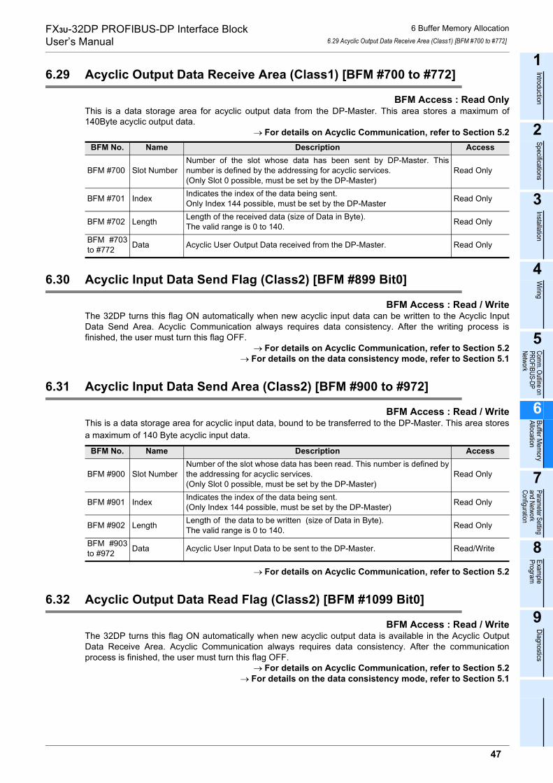
FX3U-32DP PROFIBUS-DP Interface BlockUser’s Manual
6 Buffer Memory Allocation6.29 Acyclic Output Data Receive Area (Class1) [BFM #700 to #772]
1
Introduction
2
Specifications
3
Installation
4
Wiring
5
Comm. Outline on PROFIBUS-DP Network
6
Buffer Mem
oryAllocation
7
Parameter Setting and Network Configuration
8
Example
Program
9
Diagnostics
6.29 Acyclic Output Data Receive Area (Class1) [BFM #700 to #772]
BFM Access : Read OnlyThis is a data storage area for acyclic output data from the DP-Master. This area stores a maximum of140Byte acyclic output data.
→ For details on Acyclic Communication, refer to Section 5.2
6.30 Acyclic Input Data Send Flag (Class2) [BFM #899 Bit0]
BFM Access : Read / WriteThe 32DP turns this flag ON automatically when new acyclic input data can be written to the Acyclic InputData Send Area. Acyclic Communication always requires data consistency. After the writing process isfinished, the user must turn this flag OFF.
→ For details on Acyclic Communication, refer to Section 5.2→ For details on the data consistency mode, refer to Section 5.1
6.31 Acyclic Input Data Send Area (Class2) [BFM #900 to #972]
BFM Access : Read / WriteThis is a data storage area for acyclic input data, bound to be transferred to the DP-Master. This area storesa maximum of 140 Byte acyclic input data.
→ For details on Acyclic Communication, refer to Section 5.2
6.32 Acyclic Output Data Read Flag (Class2) [BFM #1099 Bit0]
BFM Access : Read / WriteThe 32DP turns this flag ON automatically when new acyclic output data is available in the Acyclic OutputData Receive Area. Acyclic Communication always requires data consistency. After the communicationprocess is finished, the user must turn this flag OFF.
→ For details on Acyclic Communication, refer to Section 5.2→ For details on the data consistency mode, refer to Section 5.1
BFM No. Name Description Access
BFM #700 Slot NumberNumber of the slot whose data has been sent by DP-Master. Thisnumber is defined by the addressing for acyclic services.(Only Slot 0 possible, must be set by the DP-Master)
Read Only
BFM #701 Index Indicates the index of the data being sent.Only Index 144 possible, must be set by the DP-Master Read Only
BFM #702 Length Length of the received data (size of Data in Byte).The valid range is 0 to 140. Read Only
BFM #703to #772 Data Acyclic User Output Data received from the DP-Master. Read Only
BFM No. Name Description Access
BFM #900 Slot NumberNumber of the slot whose data has been read. This number is defined bythe addressing for acyclic services.(Only Slot 0 possible, must be set by the DP-Master)
Read Only
BFM #901 Index Indicates the index of the data being sent.(Only Index 144 possible, must be set by the DP-Master) Read Only
BFM #902 Length Length of the data to be written (size of Data in Byte).The valid range is 0 to 140. Read Only
BFM #903to #972 Data Acyclic User Input Data to be sent to the DP-Master. Read/Write
47

FX3U-32DP PROFIBUS-DP Interface BlockUser’s Manual
6 Buffer Memory Allocation6.33 Acyclic Output Data Receive Area (Class2) [BFM #1100 to #1172]
6.33 Acyclic Output Data Receive Area (Class2) [BFM #1100 to #1172]
BFM Access : Read OnlyThis is a data storage area for acyclic output data from the DP-Master. This area stores a maximum of 140Byte acyclic output data.
→ For details on Acyclic Communication, refer to Section 5.2
6.34 Reset Extended Diagnostic/Alarm Data Area Flag [BFM #1298]
Data consistency is necessary for the user-diagnostic and alarm (status) messages.When the Extended User-Diagnostic/Alarm (Status) Data Area is not empty, this flag turns ON. Writing "0" toBFM#1298 clears the Extended User-Diagnostic/Alarm (Status) Data Area, whereas this BFM is availableonly when the DP-Master acknowledges all the Alarm Messages.When writing "0" to BFM#1298 before the DP-Master acknowledges all the Alarm Messages, BFM#38 Bit12turns ON to show the setting error.
→ For details on BFM#38, refer to Section 6.19
6.35 Alarm/Status Switch [BFM #1299 Bit0]
BFM Access : Read / WriteWhen the communication protocol is DP-V1 (BFM#35 Bit0 is ON), the 32DP transfers its diagnostic data bydefault as an Alarm Message with high priority. The Alarm Message needs to be acknowledged by the DP-Master. When this alarm acknowledging protocol is unnecessary, the diagnostic data can be sent with lowerpriority by specifying the data as a Status Message (setting BFM#1299 Bit0 to ON).The 32DP diagnostic data varies depending on BFM#1299 Bit0 as follows.
Note
• BFM#35 Bit2 corresponds to BFM#1299 Bit0• When enabling Alarm Message (BFM#1299 Bit0 is OFF) while DP-V1 acyclic services are disabled
(BFM#35 Bit0 is OFF), the Alarm/Status Switch Error (BFM#1299 Bit13 ON) occurs.• BFM #1299 Bit0 can only be set or reset when DP-V1 support and Diagnostic Alarm support are enabled
with the DP-Master Configuration Tool.→ For details on BFM #35, refer to Section 6.16→ For details on BFM #38, refer to Section 6.19
→ For details on enabling DP-V1 support, refer to Subsection 7.1.1
BFM No. Name Description Access
BFM #1100 Slot NumberNumber of the slot whose data has been read. This number is defined bythe addressing for acyclic services.Only Slot 0 possible, must be set by the DP-Master
Read Only
BFM #1101 Index Indicates the index of the data being sent.Only Index 144 possible, must be set by the DP-Master Read Only
BFM #1102 Length Length of the data, which has been read (size of Data in Byte). The validrange is 0 to 140. Read Only
BFM #1103to #1172 Data Acyclic User Output Data being received by the DP-Master. Read Only
Bit No. Name Description
Bit 0 Alarm/Status Switch
OFF when the diagnostic message is transferred as Alarm Message withhigh priority, requiring the DP-Master acknowledgingON when the diagnostic message is transferred as Status Message withlow priority, requiring no DP-Master acknowledging
Bit 1 to 15 Not Available -
48
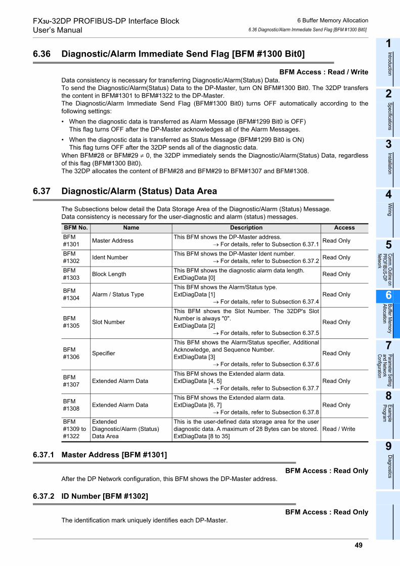
FX3U-32DP PROFIBUS-DP Interface BlockUser’s Manual
6 Buffer Memory Allocation6.36 Diagnostic/Alarm Immediate Send Flag [BFM #1300 Bit0]
1
Introduction
2
Specifications
3
Installation
4
Wiring
5
Comm. Outline on PROFIBUS-DP Network
6
Buffer Mem
oryAllocation
7
Parameter Setting and Network Configuration
8
Example
Program
9
Diagnostics
6.36 Diagnostic/Alarm Immediate Send Flag [BFM #1300 Bit0]
BFM Access : Read / WriteData consistency is necessary for transferring Diagnostic/Alarm(Status) Data.To send the Diagnostic/Alarm(Status) Data to the DP-Master, turn ON BFM#1300 Bit0. The 32DP transfersthe content in BFM#1301 to BFM#1322 to the DP-Master.The Diagnostic/Alarm Immediate Send Flag (BFM#1300 Bit0) turns OFF automatically according to thefollowing settings:• When the diagnostic data is transferred as Alarm Message (BFM#1299 Bit0 is OFF)
This flag turns OFF after the DP-Master acknowledges all of the Alarm Messages.• When the diagnostic data is transferred as Status Message (BFM#1299 Bit0 is ON)
This flag turns OFF after the 32DP sends all of the diagnostic data.When BFM#28 or BFM#29 ≠ 0, the 32DP immediately sends the Diagnostic/Alarm(Status) Data, regardlessof this flag (BFM#1300 Bit0).The 32DP allocates the content of BFM#28 and BFM#29 to BFM#1307 and BFM#1308.
6.37 Diagnostic/Alarm (Status) Data Area
The Subsections below detail the Data Storage Area of the Diagnostic/Alarm (Status) Message.Data consistency is necessary for the user-diagnostic and alarm (status) messages.
6.37.1 Master Address [BFM #1301]
BFM Access : Read OnlyAfter the DP Network configuration, this BFM shows the DP-Master address.
6.37.2 ID Number [BFM #1302]
BFM Access : Read OnlyThe identification mark uniquely identifies each DP-Master.
BFM No. Name Description AccessBFM#1301 Master Address This BFM shows the DP-Master address.
→ For details, refer to Subsection 6.37.1 Read Only
BFM#1302 Ident Number This BFM shows the DP-Master Ident number.
→ For details, refer to Subsection 6.37.2 Read Only
BFM#1303 Block Length This BFM shows the diagnostic alarm data length.
ExtDiagData [0] Read Only
BFM#1304 Alarm / Status Type
This BFM shows the Alarm/Status type.ExtDiagData [1]
→ For details, refer to Subsection 6.37.4Read Only
BFM#1305 Slot Number
This BFM shows the Slot Number. The 32DP's SlotNumber is always "0".ExtDiagData [2]
→ For details, refer to Subsection 6.37.5
Read Only
BFM#1306 Specifier
This BFM shows the Alarm/Status specifier, AdditionalAcknowledge, and Sequence Number.ExtDiagData [3]
→ For details, refer to Subsection 6.37.6
Read Only
BFM#1307 Extended Alarm Data
This BFM shows the Extended alarm data.ExtDiagData [4, 5]
→ For details, refer to Subsection 6.37.7Read Only
BFM#1308 Extended Alarm Data
This BFM shows the Extended alarm data.ExtDiagData [6, 7]
→ For details, refer to Subsection 6.37.8Read Only
BFM#1309 to#1322
Extended Diagnostic/Alarm (Status) Data Area
This is the user-defined data storage area for the userdiagnostic data. A maximum of 28 Bytes can be stored.ExtDiagData [8 to 35]
Read / Write
49

FX3U-32DP PROFIBUS-DP Interface BlockUser’s Manual
6 Buffer Memory Allocation6.37 Diagnostic/Alarm (Status) Data Area
6.37.3 Block Length [BFM # 1303]
BFM Access : Read OnlyThis BFM shows the diagnostic alarm data length.
6.37.4 Alarm/Status Type [BFM #1304]
BFM Access : Read OnlyThis BFM shows the Alarm/Status type as follows:0x01 = Alarm Message0x81 = Status Message
6.37.5 Slot Number [BFM #1305]
BFM Access : Read OnlyThis BFM comes from the PROFIBUS DP Specification, displaying the number of the special function blockssending the alarm.The 32DP’s value here is always "0".
6.37.6 Specifier [BFM #1306]
BFM Access : Read Only
*1. This specifier comes from the PROFIBUS DP Specification, displaying the message status.The 32DP’s value here is always "0X00."
*2. This also comes from the PROFIBUS DP Specification, displaying the additional acknowledge handling.The 32DP’s value here is always "0".
6.37.7 Extended Alarm Data [BFM #1307]
BFM Access : Read OnlyThe 32DP allocates the content of BFM#28 here.
6.37.8 Extended Alarm Data [BFM #1308]
BFM Access : Read OnlyThe 32DP allocates the content of BFM#29 here.
6.37.9 Extended Diagnostic/Alarm(Status) Data Area [BFM #1309 to #1322]
BFM Access : Read / WriteThis is the user-defined data storage area for the user diagnostic data. A maximum of 28 Bytes can be stored.
Bit No. Description
Bit 0Bit 1
The Alarm/Status specifier defines the message status *10x00 : No further distinction0x01 : The error occured and the slot number (BFM#1305) has an error0x02 : The error disappeared and the slot number (BFM#1305) has no error0x03 : The error disappeared and the slot number (BFM#1305) has an error
Bit 2Additional AcknowledgeON when the message needs additional acknowledging *2
Bit 3 to 7Sequence NumberThis BFM shows the sequence number of the messageThe sequence number range lies from 0 to 31
50

FX3U-32DP PROFIBUS-DP Interface BlockUser’s Manual
7 Parameter Setting and Network Configuration [GX Configurator-DP]
1
Introduction
2
Specifications
3
Installation
4
Wiring
5
Comm. Outline on PROFIBUS-DP Network
6
Buffer Mem
oryAllocation
7
Parameter Setting and Network Configuration
8
Example
Program
9
Diagnostics
7. Parameter Setting and Network Configuration [GX Configurator-DP]
To set the parameters and configure the DP network, use GX Configurator-DP (Ver.7.00A or later).→ For operation details on GX Configurator-DP, refer to
the GX Configurator-DP Software Manual→ For details on DP-Master setting procedures, refer to the respective DP-Master manual
→ For examples on setting parameters and configurations, refer to Chapter 8Note
Module typeSelect the appropriate module type in the "Network Setup" dialog box.
Operation modeThe FX3U-64DP-M PROFIBUS Master Module has 2 operation modes for cyclic communication.
- The Normal Service Mode exchanges a maximum of 32Byte/Slave.- The Extended Service Mode exchanges a maximum of 244Byte/slave.
→ For the MELSEC PROFIBUS Operation Modes, refer to the respective DP-Master manual
STARTUP AND MAINTENANCE PRECAUTIONS
• Do not touch any terminal while the PLC’s power is on.Doing so may cause electric shock or malfunctions.
• Before cleaning or retightening terminals, externally cut off all phases of the power supply.Failure to do so may cause electric shock.
• Before modifying or disrupting the program in operation or running the PLC, carefully read through this manualand the associated manuals and ensure the safety of the operation.An operation error may damage the machinery or cause accidents.
STARTUP AND MAINTENANCE PRECAUTIONS
• Do not disassemble or modify the unit.Doing so may cause fire, equipment failures, or malfunctions.* For repair, contact your local Mitsubishi Electric representative.
• Do not drop the product or expose the product to strong impacts, as doing so may cause product damage.• Turn off the power to the PLC before attaching or detaching the peripheral devices.
Failure to do so may cause equipment failures or malfunctions.
51

FX3U-32DP PROFIBUS-DP Interface BlockUser’s Manual
7 Parameter Setting and Network Configuration [GX Configurator-DP]7.1 Slave Parameter Settings
7.1 Slave Parameter Settings
The slave parameters for the 32DP must be set using the DP-Master Configuration Tool. This sectiondescribes the available parameters that are available with GX Configurator-DP.
→ For details on the "Slave Parameter Settings" dialog box,refer to the GX Configurator-DP Software Manual.
7.1.1 Slave Properties
Set the following parameters in the Slave Properties section of the "Slave Paramenter Settings" dialog boxwithin GX Configurator-DP.→ For details on the "Slave Parameter Settings" dialog box, refer to the GX Configurator-DP Software
Manual.
7.1.2 Extended User Parameters
Use the "User Param." button from the "Slave Parameter Settings" dialog box in GX Configurator-DP toenable or disable the swap byte order. The default setting is set to "disable." The "User Param." buttonopens the "Extended User Parameters" dialog box and is applicable for the Byte Swap of cyclic/acyclic I/O-Data.
→ For details on the "Slave Parameter Settings" dialog box,refer to the GX Configurator-DP Software Manual.
Parameter Description Default/Setting RangeName Name of the DP-Slave Default: Slave_Nr_001
FDL address This item defines the slave address Default: 1Range : 0 to 125
Watchdog
Check off to enable the watchdog control for the DP-SlaveThe DP-Slave monitors if the DP-Master completes thecommunication process within the preset watchdog time, and if theprocess exceeds the watchdog time, BFM #29 Bit 8 turns ON
Default: Not Checked
Slave WatchdogTime
Here, users need to set the watchdog time interval of the DP-Slavewhen the watchdog functionality is enabled.The Watchdog Time must be longer than the max. PROFIBUS CycleTime.
→ For details on PROFIBUS Cycle Time, refer tothe respective DP-Master Manual
Range: 1 to 65025 [10ms]
min T_sdr This is the minimum response time for a DP slave to send theresponse frames to the DP master. Do not change this value.
Default : 11Range : 1 to 255
GroupIdentificationNumber
Check off to allocate the DP-Slave to a group or a set of groups.The DP-Slaves in the same group operate synchronously −
Slave is activeCheck off for the master to determine the presence of the specifiedDP-SlaveThis helps users sort out the physical network connections
Default : Checked off
Sync (Output) Check off set the output data ready for the SYNC mode Default : Not CheckedFreeze (Input) Check off to set the input data ready for the FREEZE mode Default : Not CheckedSwap I/O Bytesin Master
Check off to swap the byte order for a PROFIBUS DP Module havingthe reversed-byte word format Default : Not Checked
DP V1/V2 SlaveParameters
Click this button to open the <DP V1/V2 Slave Parameters> dialogbox. Use the options to enable/disable DP-V1 Support and to setsupport for Diagnostic Alarm data. The default setting for "DP V1support enabled" is "Not checked"
−
52
FX3U-32DP PROFIBUS-DP Interface BlockUser’s Manual
7 Parameter Setting and Network Configuration [GX Configurator-DP]7.2 Network Configuration
1
Introduction
2
Specifications
3
Installation
4
Wiring
5
Comm. Outline on PROFIBUS-DP Network
6
Buffer Mem
oryAllocation
7
Parameter Setting and Network Configuration
8
Example
Program
9
Diagnostics
7.1.3 Slave Modules
Use the "Select Modules" button from the "Slave Parameter Settings" dialog box in GX Configurator-DP todefine the combinations of I/O data sets for the Slave. GX Configurator-DP automatically restricts the numberof available options.
→ For details on the "Slave Parameter Settings" dialog box,refer to the GX Configurator-DP Software Manual.
7.2 Network Configuration
Configure the PROFIBUS-DP network in the "graphical network editor" window with the GX Configurator-DPsoftware.
→ For operation details, refer to GX Configurator-DP Software Manual.
53
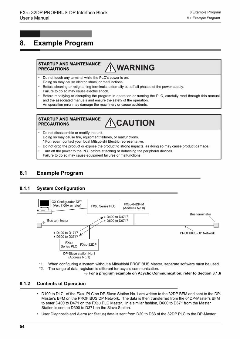
FX3U-32DP PROFIBUS-DP Interface BlockUser’s Manual
8 Example Program8.1 Example Program
8. Example Program
8.1 Example Program
8.1.1 System Configuration
*1. When configuring a system without a Mitsubishi PROFIBUS Master, separate software must be used.*2. The range of data registers is different for acyclic communication.
→ For a program example on Acyclic Communication, refer to Section 8.1.6
8.1.2 Contents of Operation
• D100 to D171 of the FX3U PLC on DP-Slave Station No.1 are written to the 32DP BFM and sent to the DP-Master’s BFM on the PROFIBUS DP Network. The data is then transferred from the 64DP-Master’s BFM to enter D400 to D471 on the FX3U PLC Master. In a similar fashion, D600 to D671 from the Master Station is sent to D300 to D371 on the Slave Station.
• User Diagnostic and Alarm (or Status) data is sent from D20 to D33 of the 32DP PLC to the DP-Master.
STARTUP AND MAINTENANCE PRECAUTIONS
• Do not touch any terminal while the PLC’s power is on.Doing so may cause electric shock or malfunctions.
• Before cleaning or retightening terminals, externally cut off all phases of the power supply.Failure to do so may cause electric shock.
• Before modifying or disrupting the program in operation or running the PLC, carefully read through this manualand the associated manuals and ensure the safety of the operation.An operation error may damage the machinery or cause accidents.
STARTUP AND MAINTENANCE PRECAUTIONS
• Do not disassemble or modify the unit.Doing so may cause fire, equipment failures, or malfunctions.* For repair, contact your local Mitsubishi Electric representative.
• Do not drop the product or expose the product to strong impacts, as doing so may cause product damage.• Turn off the power to the PLC before attaching or detaching the peripheral devices.
Failure to do so may cause equipment failures or malfunctions.
FX3U Series PLC FX3U-64DP-M(Address No.0)
FX3USeries PLC
PROFIBUS-DP Network
Bus terminator
Bus terminator
GX Configurator-DP*1
(Ver. 7.00A or later)
FX3U-32DP
DP-Slave station No.1(Address No.1)
• D400 to D471*2
• D600 to D671*2
• D100 to D171*2
• D300 to D371*2
54
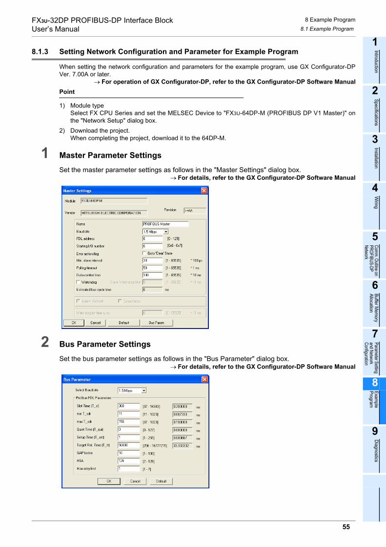
FX3U-32DP PROFIBUS-DP Interface BlockUser’s Manual
8 Example Program8.1 Example Program
1
Introduction
2
Specifications
3
Installation
4
Wiring
5
Comm. Outline on PROFIBUS-DP Network
6
Buffer Mem
oryAllocation
7
Parameter Setting and Network Configuration
8
Example
Program
9
Diagnostics
8.1.3 Setting Network Configuration and Parameter for Example Program
When setting the network configuration and parameters for the example program, use GX Configurator-DPVer. 7.00A or later.
→ For operation of GX Configurator-DP, refer to the GX Configurator-DP Software ManualPoint
1) Module typeSelect FX CPU Series and set the MELSEC Device to "FX3U-64DP-M (PROFIBUS DP V1 Master)" onthe "Network Setup" dialog box.
2) Download the project.When completing the project, download it to the 64DP-M.
1 Master Parameter Settings
Set the master parameter settings as follows in the "Master Settings" dialog box.→ For details, refer to the GX Configurator-DP Software Manual
2 Bus Parameter Settings
Set the bus parameter settings as follows in the "Bus Parameter" dialog box.→ For details, refer to the GX Configurator-DP Software Manual
55

FX3U-32DP PROFIBUS-DP Interface BlockUser’s Manual
8 Example Program8.1 Example Program
3 Network ConfigurationCreate the network configuration as follows using the "graphical network editor" window.
→ For operation details, refer to the GX Configurator-DP Software Manual
4 FX3U-32DP Setting→ For details on the Slave Parameters and Module Configuration settings,
refer to the GX Configurator-DP Software Manual
1. Slave Parameter SettingsSet the slave parameter settings for the FX3U-32DP as follows in the "Slave Parameter Settings" dialog box.
2. DP V1/V2 Slave Parameter SettingsSet the DP V1/V2 Slave Parameter Settings for the FX3U-32DP as follows in the "DP V1/V2 SlaveParameters" dialog box.
→ For details, refer to Subsection 7.1.1
56

FX3U-32DP PROFIBUS-DP Interface BlockUser’s Manual
8 Example Program8.1 Example Program
1
Introduction
2
Specifications
3
Installation
4
Wiring
5
Comm. Outline on PROFIBUS-DP Network
6
Buffer Mem
oryAllocation
7
Parameter Setting and Network Configuration
8
Example
Program
9
Diagnostics
3. Module Configuration SettingsSet the Module Configuration for the FX3U-32DP as follows in the "Slave Modules" dialog box.
→ For datails, refer to Subsection 7.1.3
57
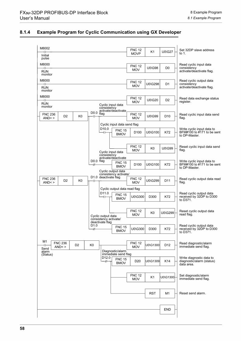
FX3U-32DP PROFIBUS-DP Interface BlockUser’s Manual
8 Example Program8.1 Example Program
8.1.4 Example Program for Cyclic Communication using GX Developer
D0.0
M8002 Set 32DP slave addressto 1.
FNC 12MOVP K1 U0\G27
Read cyclic input dataconsistencyactivate/deactivate flag.
FNC 12MOV U0\G298 D1
Read cyclic output dataconsistencyactivate/deactivate flag.
Read cyclic input data sendflag.
Reset cyclic input data sendflag.
Write cyclic input data toBFM#100 to #171 to be sentto DP-Master.
Read cyclic output datareceived by 32DP to D300to D371.
Read data exchange statusregister.
Read cyclic output data readflag.
RUNmonitor
Reset cyclic output dataread flag.
Read cyclic output datareceived by 32DP to D300to D371.
K0 U0\G99
FNC 15BMOV D100 U0\G100 K72
Write cyclic input data toBFM#100 to #171 to be sentto DP-Master.
D0.0
Write diagnostic data todiagnostic/alarm (status)data area.
Read diagnostic/alarmimmediate send flag.
Set diagnostic/alarmimmediate send flag.
Reset send alarm.
FNC 12MOV U0\G1300 D12
U0\G1309 K14
FNC 12MOV K1 U0\G1300
RST M1
M1
Sendalarm(Status)
Initialpulse
END
M8000 FNC 12MOV U0\G98 D0
RUNmonitor
FNC 12MOV U0\G20 D2
M8000
M8000
RUNmonitor
FNC 236AND< > D2 K0
D10.0 FNC 15BMOV D100 U0\G100 K72
FNC 12MOV
U0\G99 D10FNC 12MOV
D1.0
K0 U0\G299
FNC 15BMOV U0\G300 D300 K72
D1.0
FNC 236AND< > D2 K0
D11.0 FNC 15BMOV U0\G300 D300 K72
FNC 12MOV
U0\G299 D11FNC 12MOV
FNC 236AND< > D2 K0
D12.0 FNC 15BMOV D20
Cyclic input dataconsistencyactivate/deactivateflag
Cyclic input data send flag
Cyclic input dataconsistencyactivate/deactivateflag
Cyclic output dataconsistency activate/deactivate flag
Cyclic output data read flag
Cyclic output dataconsistency activate/deactivate flag
Diagnostic/alarmimmediate send flag
58

FX3U-32DP PROFIBUS-DP Interface BlockUser’s Manual
8 Example Program8.1 Example Program
1
Introduction
2
Specifications
3
Installation
4
Wiring
5
Comm. Outline on PROFIBUS-DP Network
6
Buffer Mem
oryAllocation
7
Parameter Setting and Network Configuration
8
Example
Program
9
Diagnostics
8.1.5 Example Program for Cyclic Communication using GX IEC Developer(Ver. 7.00 or later)
Set 32DP slave addressto 1.Initial
pulse
RUNmonitor
RUNmonitor
RUNmonitor
Sendalarm(Status)
Cyclic input data consistencyactivate/deactivate flag
Cyclic input data consistencyactivate/deactivate flag
Cyclic output data consistencyactivate/deactivate flag
Cyclic output data consistencyactivate/deactivate flag
Diagnostic/alarmimmediate send flag
Cyclic input data send flag
Cyclic output data read flag
Read cyclic input dataconsistencyactivate/deactivate flag.
Read cyclic output dataconsistencyactivate/deactivate flag.
Read data exchange statusregister.
Read cyclic input data sendflag.
Write cyclic input data toBFM#100 to #171 to besent to DP-Master.
Reset cyclic input datasend flag.
Write cyclic input data toBFM#100 to #171 to besent to DP-Master.
Read cyclic output dataread flag.
Read cyclic output datareceived by 32DP to D300to D371.
Reset cyclic output dataread flag.
Read cyclic output datareceived by 32DP to D300to D371.
Read diagnostic/alarmimmediate send flag.
Write diagnostic data todiagnostic/alarm (status)data area.
Set diagnostic/alarmimmediate send flag.
Reset send alarm.
1
59
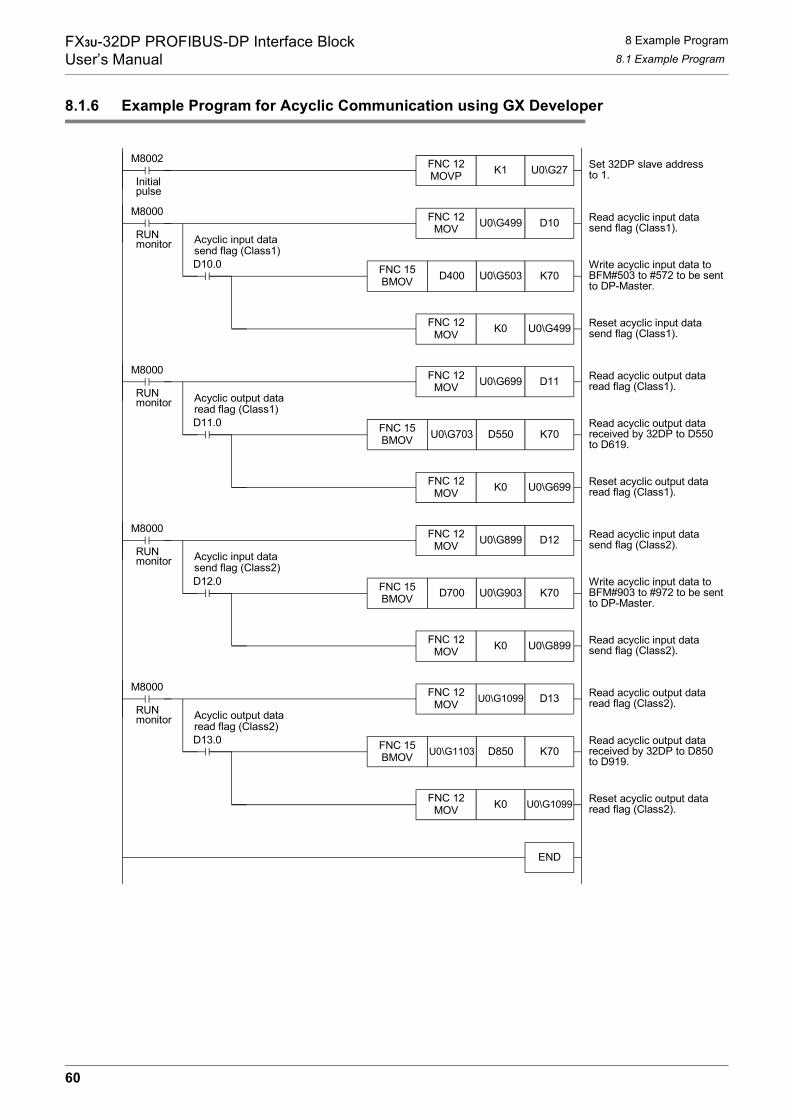
FX3U-32DP PROFIBUS-DP Interface BlockUser’s Manual
8 Example Program8.1 Example Program
8.1.6 Example Program for Acyclic Communication using GX Developer
M8002 Set 32DP slave addressto 1.
FNC 12MOVP K1 U0\G27
Read acyclic input datasend flag (Class1).
U0\G503 K70Write acyclic input data toBFM#503 to #572 to be sentto DP-Master.
Read acyclic output dataread flag (Class1).
Reset acyclic output dataread flag (Class1).
Read acyclic input datasend flag (Class2).
Read acyclic input datasend flag (Class2).
Reset acyclic input datasend flag (Class1).
Write acyclic input data toBFM#903 to #972 to be sentto DP-Master.
Read acyclic output dataread flag (Class2).
Read acyclic output datareceived by 32DP to D850to D919.
Read acyclic output datareceived by 32DP to D550to D619.
Reset acyclic output dataread flag (Class2).
Initialpulse
END
M8000 FNC 12MOV U0\G499 D10
RUNmonitor
FNC 12MOV K0 U0\G499
D10.0 FNC 15BMOV D400
D550 K70
M8000 FNC 12MOV U0\G699 D11
RUNmonitor
FNC 12MOV K0 U0\G699
D11.0 FNC 15BMOV U0\G703
U0\G903 K70
M8000 FNC 12MOV U0\G899 D12
RUNmonitor
FNC 12MOV K0 U0\G899
D12.0 FNC 15BMOV D700
D850 K70
M8000 FNC 12MOV U0\G1099 D13
RUNmonitor
FNC 12MOV K0 U0\G1099
D13.0 FNC 15BMOV U0\G1103
Acyclic input datasend flag (Class1)
Acyclic output dataread flag (Class1)
Acyclic input datasend flag (Class2)
Acyclic output dataread flag (Class2)
60

FX3U-32DP PROFIBUS-DP Interface BlockUser’s Manual
8 Example Program8.1 Example Program
1
Introduction
2
Specifications
3
Installation
4
Wiring
5
Comm. Outline on PROFIBUS-DP Network
6
Buffer Mem
oryAllocation
7
Parameter Setting and Network Configuration
8
Example
Program
9
Diagnostics
8.1.7 Example Program for Acyclic Communication using GX IEC Developer(Ver. 7.00 or later)
Set 32DP slave addressto 1.Initial pulse
RUNmonitor
RUNmonitor
RUNmonitor
RUNmonitor
Acyclic input datasend flag (Class1)
Acyclic output dataread flag (Class1)
Acyclic output dataread flag (Class2)
Acyclic input datasend flag (Class2)
Read acyclic input datasend flag (Class1).
Write acyclic input data toBFM#503 to #572 to besent to DP-Master.
Reset acyclic input datasend flag (Class1).
Read acyclic output dataread flag (Class1).
Read acyclic output datareceived by 32DP to D550to D619.
Reset acyclic output dataread flag (Class1).
Read acyclic input datasend flag (Class2).
Write acyclic input data toBFM#903 to #972 to besent to DP-Master.
Read acyclic input datasend flag (Class2).
Read acyclic output dataread flag (Class2).
Read acyclic output datareceived by 32DP to D850to D919.
Reset acyclic output dataread flag (Class2).
1
61
FX3U-32DP PROFIBUS-DP Interface BlockUser’s Manual
9 Diagnostics
9. Diagnostics
STARTUP AND MAINTENANCE PRECAUTIONS
• Do not touch any terminal while the PLC’s power is on.Doing so may cause electric shock or malfunctions.
• Before cleaning or retightening terminals, externally cut off all phases of the power supply.Failure to do so may cause electric shock.
• Before modifying or disrupting the program in operation or running the PLC, carefully read through this manualand the associated manuals and ensure the safety of the operation.An operation error may damage the machinery or cause accidents.
STARTUP AND MAINTENANCE PRECAUTIONS
• Do not disassemble or modify the unit.Doing so may cause fire, equipment failures, or malfunctions.* For repair, contact your local Mitsubishi Electric representative.
• Do not drop the product or expose the product to strong impacts, as doing so may cause product damage.• Turn off the power to the PLC before attaching or detaching the peripheral devices.
Failure to do so may cause equipment failures or malfunctions.
62
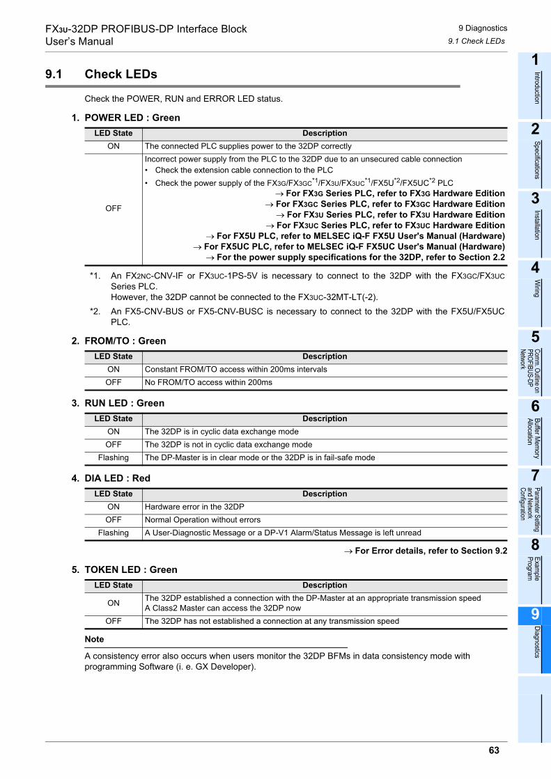
FX3U-32DP PROFIBUS-DP Interface BlockUser’s Manual
9 Diagnostics9.1 Check LEDs
1
Introduction
2
Specifications
3
Installation
4
Wiring
5
Comm. Outline on PROFIBUS-DP Network
6
Buffer Mem
oryAllocation
7
Parameter Setting and Network Configuration
8
Example
Program
9
Diagnostics
9.1 Check LEDs
Check the POWER, RUN and ERROR LED status.
1. POWER LED : Green
*1. An FX2NC-CNV-IF or FX3UC-1PS-5V is necessary to connect to the 32DP with the FX3GC/FX3UCSeries PLC.However, the 32DP cannot be connected to the FX3UC-32MT-LT(-2).
*2. An FX5-CNV-BUS or FX5-CNV-BUSC is necessary to connect to the 32DP with the FX5U/FX5UCPLC.
2. FROM/TO : Green
3. RUN LED : Green
4. DIA LED : Red
→ For Error details, refer to Section 9.2
5. TOKEN LED : Green
Note
A consistency error also occurs when users monitor the 32DP BFMs in data consistency mode with programming Software (i. e. GX Developer).
LED State DescriptionON The connected PLC supplies power to the 32DP correctly
OFF
Incorrect power supply from the PLC to the 32DP due to an unsecured cable connection• Check the extension cable connection to the PLC• Check the power supply of the FX3G/FX3GC*1/FX3U/FX3UC*1/FX5U*2/FX5UC*2 PLC
→ For FX3G Series PLC, refer to FX3G Hardware Edition→ For FX3GC Series PLC, refer to FX3GC Hardware Edition
→ For FX3U Series PLC, refer to FX3U Hardware Edition→ For FX3UC Series PLC, refer to FX3UC Hardware Edition
→ For FX5U PLC, refer to MELSEC iQ-F FX5U User's Manual (Hardware)→ For FX5UC PLC, refer to MELSEC iQ-F FX5UC User's Manual (Hardware)
→ For the power supply specifications for the 32DP, refer to Section 2.2
LED State DescriptionON Constant FROM/TO access within 200ms intervalsOFF No FROM/TO access within 200ms
LED State DescriptionON The 32DP is in cyclic data exchange modeOFF The 32DP is not in cyclic data exchange mode
Flashing The DP-Master is in clear mode or the 32DP is in fail-safe mode
LED State DescriptionON Hardware error in the 32DPOFF Normal Operation without errors
Flashing A User-Diagnostic Message or a DP-V1 Alarm/Status Message is left unread
LED State Description
ON The 32DP established a connection with the DP-Master at an appropriate transmission speedA Class2 Master can access the 32DP now
OFF The 32DP has not established a connection at any transmission speed
63
FX3U-32DP PROFIBUS-DP Interface BlockUser’s Manual
9 Diagnostics9.2 Checking Errors
9.2 Checking Errors
The following BFM has read/write access. Check the following BFM status to determine the error cause.
1. General Error [BFM #29 Bit 0]This bit is set to ON if one or more of BFM#29’s Bit1, 8-13 is ON. The 32DP attempts to send diagnostic datafrom BFM#28 and BFM#29 to the DP-Master while suspending normal data exchange when the GeneralError bit (BFM#29 Bit0) is ON.
2. PLC in STOP Mode [BFM #29 Bit 1]This bit is set to ON if the connected PLC is in STOP Mode.
3. Extended-UserAlarm/Diagnostic Data Not Yet Sent Flag[BFM #29 Bit 2]This bit is set to ON if the Extended-UserAlarm/Diagnostic Data has not yet been sent, or if it has not yet beenacknowledged by the DP-master. This flag functions similar to the "Diagnostics Status Flag" in BFM#25 Bit2.
4. Hardware Error [BFM #29 Bit 3]This bit is set to ON if an error occurs while initializing the 32DP or if a hardware error occurs during RUN.While this bit is ON, the 32DP halts communication with the DP-Master and only FROM instructions canoperate for error checking.
5. EEPROM Error [BFM #29 Bit 4]This bit is set to ON if an error occurs while initializing the 32DP EEPROM or if the slave address data in theEEPROM becomes corrupt. The EEPROM data may be damaged or destroyed. This bit correspondsdirectly with BFM#29 Bit3.
6. Consistency Handling Error Flags [BFM #29 Bit 5]This bit is set to ON when the 32DP detects an error with data consistency handling. Further information isprovided in BFM#37 for the type of consistency error. Resetting this bit will also reset BFM#37.
→ For details on the Consistency Handling Error Flags BFM#37, refer to Section 6.18
7. Setting Error Flag [BFM #29 Bit 6]This bit is set to ON if an invalid setting is written to one of the 32DP’s BFM addresses. Further information isprovided in BFM#38 for the type of error. Resetting this bit will also reset BFM#38.
→ For details on the Setting Error Flag BFM#38, refer to Section 6.19
8. Watchdog DP Timeout Flag [BFM #29 Bit 8]This bit is set to ON if the DP-Watchdog timer expires in the DP-control state. No requests were made to theDP-Master within the projected watchdog time. Causes may include a faulty PROFIBUS cable connection.
9. Acyclic Communication Error [BFM #29 Bit 9]This bit is set to ON when an error occurs in (DP-V1) acyclic communication. Further information is providedin BFM#35 for the type of acyclic communication error. Resetting this bit will also reset BFM#35.→ For details on the DP-V1 Communication Parameter BFM#35, refer to Section 6.16 [BFM #29 Bit 10]
10.Configuration Error [BFM #29 Bit 10]This bit is set to ON if invalid configuration data is received from the DP-Master.
11.Parameter Error [BFM #29 Bit 11]This bit is set to ON if invalid parameter data is received from the DP-Master.
12.Slave Address Change Error [BFM #29 Bit 12]This bit turns ON if the user sets the 32DP slave address to a value greater than 126 in BFM#27 or if theslave address is set to greater than 125 when setting via SSA-telegram. This bit automatically resets itselfwhen the 32DP slave address is set correctly via BFM or SSA.
→ For details on setting the Slave Address BFM#27, refer to Section 6.10
13.Slave "Reset No Address Change" Error [BFM #29 Bit 13]This bit turns ON when the 32DP detects an error due to resetting the Address Change Impossible Flag(BFM#25 Bit8) while the slave is in Data Exchange mode, or when the Address Change Impossible Flag(BFM#25 Bit8) is reset while the write access to BFM#25 Bit8 is disabled.
64

FX3U-32DP PROFIBUS-DP Interface BlockUser’s Manual Warranty
WarrantyPlease confirm the following product warranty details before using this product.
1. Gratis Warranty Term and Gratis Warranty Range
[Gratis Warranty Term]
If any faults or defects (hereinafter "Failure") found to be the responsibility of Mitsubishi occurs during use of the product within the gratis warranty term, the product shall be repaired at no cost via the sales representative or Mitsubishi Service Company. However, if repairs are required onsite at domestic or overseas location, expenses to send an engineer will be solely at the customer's discretion. Mitsubishi shall not be held responsible for any re-commissioning, maintenance, or testing on-site that involves replacement of the failed module. Overseas, repairs shall be accepted by Mitsubishi's local
overseas FA Center. Note that the repair conditions at each FA Center may differ. The gratis warranty term of the product shall be for one
year after the date of purchase or delivery to a designated place. Note that after manufacture and shipment from Mitsubishi, the maximum distribution period shall be six (6) months, and the longest gratis warranty term after manufacturing shall be eighteen (18) months. The gratis warranty term of repair parts shall not exceed the gratis warranty term before repairs. [Gratis Warranty Range]
The range shall be limited to normal use within the usage state, usage methods and usage environment, etc., which follow the conditions and precautions, etc., given in the instruction manual, user's manual and caution labels on the product.
(1)
Even within the gratis warranty term, repairs shall be charged for in the following cases.
(2)
Failure occurring from inappropriate storage or handling, carelessness or negligence by the user. Failure caused by the user's hardware or software design.
1.
Failure caused by unapproved modifications, etc., to the product by the user.
2.
Mitsubishi shall accept onerous product repairs for seven (7) years after production of the product is discontinued.Discontinuation of production shall be notified with Mitsubishi Technical Bulletins, etc.
(1)
Product supply (including repair parts) is not available after production is discontinued.
(2)
In using the Mitsubishi MELSEC programmable logic controller, the usage conditions shall be that the application will not lead to a major accident even if any problem or fault should occur in the programmable logic controller device, and that backup and fail-safe functions are systematically provided outside of the device for any problem or fault.
(1)
Damages caused by any cause found not to be the responsibility of Mitsubishi.
(1)
Loss in opportunity, lost profits incurred to the user by Failures of Mitsubishi products.
(2)
Special damages and secondary damages whether foreseeable or not, compensation for accidents, and compensation for damages to products other than Mitsubishi products.
(3)
Replacement by the user, maintenance of on-site equipment, start-up test run and other tasks.
(4)
The Mitsubishi programmable logic controller has been designed and manufactured for applications in general industries, etc. Thus, applications in which the public could be affected such as in nuclear power plants and other power plants operated by respective power companies, and applications in which a special quality assurance system is required, such as for Railway companies or Public service purposes shall be excluded from the programmable logic controller applications. In addition, applications in which human life or property that could be greatly affected, such as in aircraft, medical applications, incineration and fuel devices, manned transportation, equipment for recreation and amusement, and safety devices, shall also be excluded from the programmable logic controller range of applications. However, in certain cases, some applications may be possible, providing the user consults their local Mitsubishi representative outlining the special requirements of the project, and providing that all parties concerned agree to the special circumstances, solely at the users discretion.
(2)
When the Mitsubishi product is assembled into a user's device, Failure that could have been avoided if functions or structures, judged as necessary in the legal safety measures the user's device is subject to or as necessary by industry standards, had been provided.
3.
Failure that could have been avoided if consumable parts (battery, backlight, fuse, etc.) designated in the instruction manual had been correctly serviced or replaced.
4.
Relay failure or output contact failure caused by usage beyond the specified Life of contact (cycles).
5.
Failure caused by external irresistible forces such as fires or abnormal voltages, and failure caused by force majeure such as earthquakes, lightning, wind and water damage.
6.
Failure caused by reasons unpredictable by scientific technology standards at time of shipment from Mitsubishi.
7.
Any other failure found not to be the responsibility of Mitsubishi or that admitted not to be so by the user.
8.
2. Onerous repair term after discontinuation of production
4. Exclusion of loss in opportunity and secondary loss from warranty liability
3. Overseas service
The specifications given in the catalogs, manuals or technical documents are subject to change without prior notice.
5. Changes in product specifications
6. Product application
Regardless of the gratis warranty term, Mitsubishi shall not be liable for compensation to:
65

FX3U-32DP PROFIBUS-DP Interface BlockUser’s Manual Revised History
Revised History
Date Revision Description3/2007 A First Edition
9/2007 B Changed BFM Descriptions [Section 6.35 and 6.37]
2/2011 C • The FX3G/FX3UC Series was added. [FX3UC-32MT-LT(-2) is excluded.]• The notation change of "Compliance with EC directive."• The manual is added to Associated Manuals.• Errors are corrected.
4/2015 D • A part of the cover design is changed.
11/2016 E • The FX3GC Series was added.• The FX5U/FX5UC was added.
66


HEAD OFFICE : TOKYO BUILDING, 2-7-3 MARUNOUCHI, CHIYODA-KU, TOKYO 100-8310, JAPAN
JY997D25201E(MEE)
Effective November 2016Specifications are subject to change without notice.
USER’S MANUAL
FX3U-32DP PROFIBUS-DP Interface Block