Embed Size (px)
Citation preview
MELSEC FX Series
Programmable Logic Controllers
User's Manual
Profibus/DP Interface UnitFX2N-32DP-IF
FX2N-32DP-IF-D
INDUSTRIAL AUTOMATIONMITSUBISHI ELECTRIC
MITSUBISHI ELECTRIC
Art. no.: 12821101 03 2002JY992D79401Version D

Foreword
• This manual contains text, diagrams and explanations which will guide the reader in thecorrect installation and operation of the FX2N-32DP-IF Profibus-DP Interface Unit. It shouldbe read and understood before attempting to install or use the unit.
• Further information can be found in the FX2N Series and FX0/FX0N Series HardwareManual, manuals for special function units/blocks and Profibus-DP master CPUs.
• If in doubt at any stage during the installation of the FX2N-32DP-IF Profibus-DP InterfaceUnit always consult a professional electrical engineer who is qualified and trained to thelocal and national standards.
• If in doubt about operation or use of the FX2N-32DP-IF Profibus-DP Interface Unit pleaseconsult the nearest Mitsubishi Electric distributor.
• This manual is subject to change without notice.
FX2N-32DP-IF Profibus-DP Interface Unit
i
FX2N-32DP-IF Profibus-DP Interface Unit
User’s Manual
Manual number : JY992D79401
Manual revision : D
Date : March 2002
FX2N-32DP-IF Profibus-DP Interface Unit

FX2N-32DP-IF Profibus-DP Interface Unit
ii

FAX BACK
Mitsubishi has a world wide reputation for its efforts in continually developing and pushing backthe frontiers of industrial automation. What is sometimes overlooked by the user is the careand attention to detail that is taken with the documentation. However,to continue this processof improvement, the comments of the Mitsubishi users are always welcomed. This page hasbeen designed for you,the reader,to fill in your comments and fax them back to us. We lookforward to hearing from you.
Fax numbers: Your name....................................................
Mitsubishi Electric.... .....................................................................
America (01) 847-478-2253 Your company ..............................................
Australia (02) 638-7072 .....................................................................
Germany (0 21 02) 4 86-1 12 Your location:................................................
Spain (0 34) 93 589-1579 .....................................................................
United Kingdom (01707) 278-695
Please tick the box of your choice
What condition did the manual arrive in? Good Minor damage Unusable
Will you be using a folder to store the manual?Yes No
What do you think to the manual presentation?Tidy Un-friendly
Are the explanations understandable? Yes Not too bad Unusable
Which explanation was most difficult to understand: ......................................................................................................................................................................................................................
Are there any diagrams which are not clear? Yes No
If so,which: ..................................................................................................................................
What do you think to the manual layout? Good Not too bad Un-helpful
If there one thing you would like to see improved,what is it? ..............................................................................................................................................................................................................................................................................................................................................................
Could you find the information you required easily using the index and/or the contents,ifpossible please identify your experience: ...................................................................................................................................................................................................................................................................................................................................................................................................................................................................................................................................................................................................................................................................................................
Do you have any comments in general about the Mitsubishi manuals? .....................................................................................................................................................................................................................................................................................................................................................................................................................................................................................................................................................................................................................................................
Thank you for taking the time to fill out this questionnaire. We hope you found both the productand this manual easy to use.
FX2N-32DP-IF Profibus-DP Interface Unit
iii

FX2N-32DP-IF Profibus-DP Interface Unit
iv
FX2N-32DP-IF Profibus-DP Interface Unit
v
Guidelines for the Safety of the User and Protection of the FX2N-32DP-IF Profibus-DP Interface Unit.
This manual provides information for the use of the FX2N-32DP-IF Profibus-DP Interface Unit.The manual has been written to be used by trained and competent personnel. The definition ofsuch a person or persons is as follows:
a) Any engineer who is responsible for the planning, design and construction of automaticequipment using the product associated with this manual should be of a competentnature, trained and qualified to the local and national standards required to fulfill thatrole. These engineers should be fully aware of all aspects of safety with regards toautomated equipment.
b) Any commissioning or service engineer must be of a competent nature, trained andqualified to the local and national standards required to fulfill that job. These engineersshould also be trained in the use and maintenance of the completed product. Thisincludes being completely familiar with all associated documentation for the said product.All maintenance should be carried out in accordance with established safety practices.
c) All operators of the completed equipment should be trained to use that product in a safeand coordinated manner in compliance to established safety practices. The operatorsshould also be familiar with documentation which is connected with the actual operationof the completed equipment.
Note : the term ‘completed equipment’ refers to a third party constructed device whichcontains or uses the product associated with this manual.
Notes on the Symbols Used in this Manual
At various times through out this manual certain symbols will be used to highlight points ofinformation which are intended to ensure the users personal safety and protect the integrity ofthe equipment. Whenever any of the following symbols are encountered its associated notemust be read and understood. Each of the symbols used will now be listed with a briefdescription of its meaning.
Hardware Warnings
1) Indicates that the identified danger WILL cause physical and property damage.
2) Indicates that the identified danger could POSSIBLY cause physical and propertydamage.
3) Indicates a point of further interest or further explanation.
Software Warnings
4) Indicates special care must be taken when using this element of software.
5) Indicates a special point which the user of the associate software element shouldbe aware of.
6) Indicates a point of interest or further explanation.

FX2N-32DP-IF Profibus-DP Interface Unit
vi
• Under no circumstances will Mitsubishi Electric be liable responsible for any consequentialdamage that may arise as a result of the installation or use of this equipment.
• All examples and diagrams shown in this manual are intended only as an aid tounderstanding the text, not to guarantee operation. Mitsubishi Electric will accept noresponsibility for actual use of the product based on these illustrative examples.
• Please contact a Mitsubishi distributor for more information concerning applications in lifecritical situations or high reliability.
vii
Table of Contents
Guideline of Safety ...............................................................................v
1. Introduction............................................................................................1-11.1 Features of the 32DP-IF ...................................................................................... 1-11.2 External Dimensions and Each Part Name ......................................................... 1-2
1.2.1 Pin Configuration ....................................................................................................... 1-31.3 System Configuration .......................................................................................... 1-4
1.3.1 Connected Programming Tools................................................................................. 1-41.3.2 Connected Extension Units/Blocks ........................................................................... 1-51.3.3 Configuration Rules ................................................................................................... 1-71.3.4 Example Configuration ............................................................................................ 1-20
2. Mounting................................................................................................2-12.1 Mounting Arrangements ...................................................................................... 2-12.2 Mounting.............................................................................................................. 2-2
2.2.1 DIN Rail Mounting ..................................................................................................... 2-22.2.2 Direct Mounting to Back Walls .................................................................................. 2-2
3. Wiring ....................................................................................................3-13.1 Caution for Wiring................................................................................................ 3-13.2 Power Supply ...................................................................................................... 3-3
3.2.1 AC Power Supply Type: FX2N-32DP-IF .................................................................... 3-33.2.2 DC Power Supply Type: FX2N-32DP-IF-D ................................................................ 3-4
3.3 Profibus-DP Network ........................................................................................... 3-53.4 Input in Extension Units/Blocks ........................................................................... 3-6
3.4.1 DC Sink Input ............................................................................................................ 3-63.4.2 DC Source Input ........................................................................................................ 3-73.4.3 AC Input .................................................................................................................... 3-8
3.5 Output in Extension Units/Blocks ........................................................................ 3-93.5.1 Relay Output ............................................................................................................. 3-93.5.2 Transistor Output..................................................................................................... 3-10
3.6 Special Function Units/Blocks .......................................................................... 3-10
4. Specifications ........................................................................................4-14.1 General Specifications......................................................................................... 4-14.2 Power Supply Specifications ............................................................................... 4-24.3 Performance Specifications................................................................................. 4-2
5. Advanced Devices.................................................................................5-15.1 Data Registers..................................................................................................... 5-1
5.1.1 Example of Allocating Device .................................................................................... 5-25.2 Diagnostic Devices (Special Devices) ................................................................. 5-3
5.2.1 32DP-IF Status (M8000 ~ M8009 and D8000 ~ D8009) ........................................... 5-45.2.2 Clock Devices (D8010 ~ D8019) ............................................................................... 5-55.2.3 Profibus-DP Network Status (M8020 ~ M8039 and D8020 ~ D8039) ....................... 5-65.2.4 Configuration Status (M8040 ~ M8059 and D8040 ~ D8059) ................................. 5-105.2.5 Error Status (M8060 ~ M8069 and D8060 ~ D8069) .............................................. 5-11
FX2N-32DP-IF Profibus-DP Interface Unit
FX2N-32DP-IF Profibus-DP Interface Unit
viii
6. Address Setting .....................................................................................6-16.1 Setting the Address ............................................................................................. 6-16.2 Example Address Setting .................................................................................... 6-1
7. User Parameter .....................................................................................7-17.1 User Parameter Rules ......................................................................................... 7-17.2 Default User Parameter ....................................................................................... 7-6
7.2.1 Exchanged Data by Default User Parameter ............................................................ 7-97.2.2 Exchanged Data Process by Simple Communication Interface .............................. 7-12
7.3 Configuring Slave Parameter ............................................................................ 7-137.3.1 Configuring Slave Parameter by GSD file ............................................................... 7-137.3.2 Configuring Slave Parameter by Programming Tool ............................................... 7-14
8. Diagnostic Message ..............................................................................8-18.1 Diagnostic Message Frame................................................................................. 8-18.2 Diagnostic Message Contents List ...................................................................... 8-1
9. Diagnostics............................................................................................9-19.1 Preliminary Checks.............................................................................................. 9-19.2 Check the Status of the LEDs of the 32DP-IF ..................................................... 9-29.3 Check Error Status of the 32DP-IF...................................................................... 9-3
9.3.1 Error Status in D8029................................................................................................ 9-39.3.2 Error Flags................................................................................................................. 9-49.3.3 Error Code................................................................................................................. 9-5
Appendix AExample Parameter and Configuration on ProfiMap................................ A-1
A-1: System Configuration ..........................................................................................A-1A-2: Set System Configuration with ProfiMap .............................................................A-2A-3: Set User Parameter with ProfiMap ......................................................................A-5
Appendix BExample Parameter and Configuration on GX-Configurator-DP.............. B-1
B-1: System Configuration ..........................................................................................B-1B-2: Set System Configuration with GX-Configurator-DP ...........................................B-2B-3: Set User Parameter with GX-Configurator-DP ....................................................B-5
FX2N-32DP-IF Profibus-DP Interface Unit
ix
Appendix CUser Parameter ........................................................................................C-1
C-1: General Parameter (Global User Parameter) ..................................................... C-1C-2: User Parameter for Special function block ......................................................... C-3
C-2-1: FX2N-4AD Extension Configuration (Intel Format)................................................... C-3C-2-2: FX2N-4AD Extension Configuration (Motorola Format)............................................ C-7C-2-3: FX2N-4AD Short Configuration (Intel Format) ........................................................ C-11C-2-4: FX2N-4AD Short Configuration (Motorola Format)................................................. C-13C-2-5: FX2N-4DA Extension Configuration (Intel Format)................................................. C-15C-2-6: FX2N-4DA Extension Configuration (Motorola Format).......................................... C-18C-2-7: FX2N-4DA Short Configuration (Intel Format) ........................................................ C-21C-2-8: FX2N-4DA Short Configuration (Motorola Format)................................................. C-23C-2-9: FX2N-4AD-PT Extension Configuration .................................................................. C-25C-2-10:FX2N-4AD-PT Short Configuration ........................................................................ C-27C-2-11:FX2N-4AD-TC Extension Configuration (Intel Format) .......................................... C-28C-2-12:FX2N-4AD-TC Extension Configuration (Motorola Format) ................................... C-30C-2-13:FX2N-4AD-TC Short Configuration (Intel Format) ................................................. C-32C-2-14:FX2N-4AD-TC Short Configuration (Motorola Format) .......................................... C-34C-2-15:FX2N-1HC Extension Configuration ...................................................................... C-36C-2-16:FX2N-1HC Short Configuration.............................................................................. C-38C-2-17:FX2N-1PG (Intel Format) ....................................................................................... C-40C-2-18:FX2N-1PG (Motorola Format) ................................................................................ C-44C-2-19:FX2N-232IF (Intel Format) ..................................................................................... C-47C-2-20:FX2N-232IF (Motorola Format) .............................................................................. C-49C-2-21:FX2N-32ASI-M ....................................................................................................... C-51C-2-22:FX0N-3A................................................................................................................. C-52C-2-23:FX2N-2AD .............................................................................................................. C-52C-2-24:FX2N-2DA .............................................................................................................. C-52C-2-25:FX2N-10GM, FX2N-20GM ..................................................................................... C-53C-2-26:FX2N-2LC (Intel Format) ........................................................................................ C-54C-2-27:FX2N-2LC (Motorola Format) ................................................................................. C-56C-2-28:FX2N-8AD (Intel Format)........................................................................................ C-58C-2-29:FX2N-8AD (Motorola Format) ................................................................................ C-61C-2-30:FX2N-10PG (Intel Format) ..................................................................................... C-64C-2-31:FX2N-10PG (Motorola Format) .............................................................................. C-68C-2-32:FX2N-10PG (Intel Format) - Using 6W-IF - ............................................................ C-72C-2-33:FX2N-10PG (Motorola Format) - Using 6W-IF - ..................................................... C-75C-2-34:Simple Communication 3W-IF (Intel Format/Motorola Fromat) ............................. C-79C-2-35:Simple Communication 6W-IF (Intel Format/Motorola Fromat) ............................. C-80C-2-36:Simple Communication 9W-IF (Intel Format/Motorola Fromat) ............................. C-81C-2-37:Simple Communication 12W-IF (Intel Format/Motorola Fromat) ........................... C-82C-2-38:Simple Communication 15W-IF (Intel Format/Motorola Fromat) ........................... C-84C-2-39:8 Bit Input............................................................................................................... C-85C-2-40:8 Bit Output............................................................................................................ C-85
Appendix DUpdate History of FX2N-32DP-IF and GSD File .......................................D-1
Appendix EFurther Information Manual Lists.............................................................. E-1

FX2N-32DP-IF Profibus-DP Interface Unit
x
Introduction 1
1-1
1. Introduction
The FX2N-32DP-IF(-D) Profibus-DP Interface Unit (hereafter called “32DP-IF”) can be used toconnect FX2N/FX0N series extension blocks/units and special function blocks/units directly toan existing Profibus-DP network.
The 32DP-IF provides an intelligent slave function for decentralized control applications. Digitaland analog data from a Profibus-DP master CPU (hereafter called “DP-master”) can be sentand received to/from any of the supported I/O blocks and special function blocks.
1.1 Features of the 32DP-IF
Using the 32DP-IF FX2N/FX0N series extension blocks/units or special function blocks/units canexchange data with any DP-master.
• Up to 256 I/O points and/or up to 8 special function blocks can be connected to the 32DP-IF.However, adjust total control I/O points to 256 or less. See section 1.3.
• The slave address of the 32DP-IF is adjusted by DIP switches. See chapter 6.
• The 32DP-IF can be connected to a Profibus-DP network via a standard 9-pin D-SUBconnector and a shielded twisted pair cable complying with EN50170. Optional glassfiberadapters are supported by the 32DP-IF and are available from other vendors.See chapter 3.
• An FX-20P-E or personal computer can be used to monitor the status of the 32DP-IF andthe data exchanged with the Profibus network. For operating instructions of the FX-20P-E orpersonal computer, refer to their respective operation manuals and to section 1.3.1. Fordevice numbers and explanation, refer to Chapter 5. For parameter of 32DP-IF.
FX2N-32DP-IF Profibus-DP Interface Unit
FX2N-32DP-IF Profibus-DP Interface Unit Introduction 1
1-2
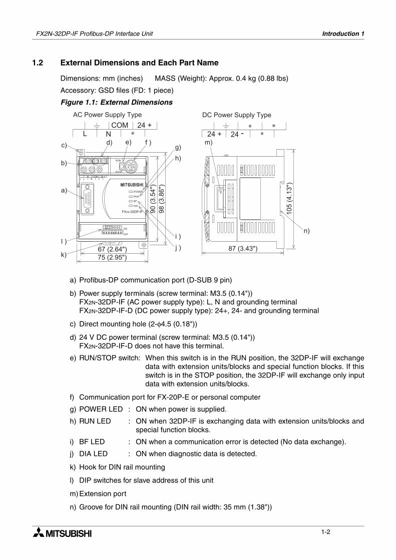
1.2 External Dimensions and Each Part Name
Dimensions: mm (inches) MASS (Weight): Approx. 0.4 kg (0.88 lbs)
Accessory: GSD files (FD: 1 piece)
Figure 1.1: External Dimensions
a) Profibus-DP communication port (D-SUB 9 pin)
b) Power supply terminals (screw terminal: M3.5 (0.14"))FX2N-32DP-IF (AC power supply type): L, N and grounding terminalFX2N-32DP-IF-D (DC power supply type): 24+, 24- and grounding terminal
c) Direct mounting hole (2-φ4.5 (0.18"))
d) 24 V DC power terminal (screw terminal: M3.5 (0.14"))FX2N-32DP-IF-D does not have this terminal.
e) RUN/STOP switch: When this switch is in the RUN position, the 32DP-IF will exchangedata with extension units/blocks and special function blocks. If thisswitch is in the STOP position, the 32DP-IF will exchange only inputdata with extension units/blocks.
f) Communication port for FX-20P-E or personal computer
g) POWER LED : ON when power is supplied.
h) RUN LED : ON when 32DP-IF is exchanging data with extension units/blocks andspecial function blocks.
i) BF LED : ON when a communication error is detected (No data exchange).
j) DIA LED : ON when diagnostic data is detected.
k) Hook for DIN rail mounting
l) DIP switches for slave address of this unit
m)Extension port
n) Groove for DIN rail mounting (DIN rail width: 35 mm (1.38"))
!"
!"
# ! "# ! "
!"
# ! "
$ "
% "
& "
' " ( " ) "* "
+ "
, "
- ". "
/ "
0 "
1 "
2 3 ( 4 5 6 6 / 7 7 6 (
2 3 ( 4 5 6 6 / 7 7 6 (
FX2N-32DP-IF Profibus-DP Interface Unit Introduction 1
1-3
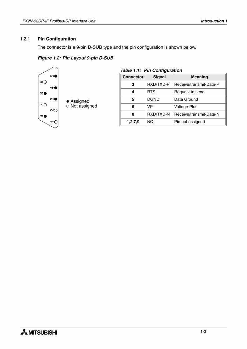
1.2.1 Pin Configuration
The connector is a 9-pin D-SUB type and the pin configuration is shown below.
Figure 1.2: Pin Layout 9-pin D-SUB
Table 1.1: Pin ConfigurationConnector Signal Meaning
3 RXD/TXD-P Receive/transmit-Data-P
4 RTS Request to send
5 DGND Data Ground
6 VP Voltage-Plus
8 RXD/TXD-N Receive/transmit-Data-N
1,2,7,9 NC Pin not assigned
AssignedNot assigned
12
6
3
79
54
8
FX2N-32DP-IF Profibus-DP Interface Unit Introduction 1
1-4
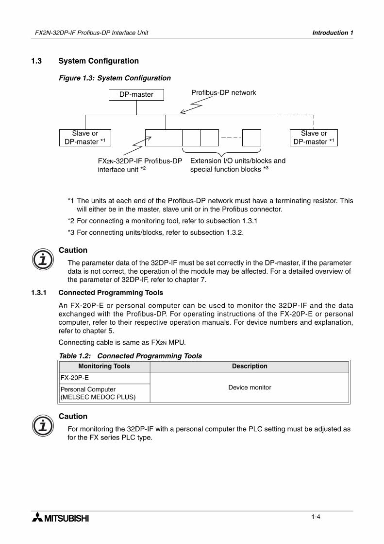
1.3 System Configuration
Figure 1.3: System Configuration
*1 The units at each end of the Profibus-DP network must have a terminating resistor. Thiswill either be in the master, slave unit or in the Profibus connector.
*2 For connecting a monitoring tool, refer to subsection 1.3.1
*3 For connecting units/blocks, refer to subsection 1.3.2.
Caution
The parameter data of the 32DP-IF must be set correctly in the DP-master, if the parameter data is not correct, the operation of the module may be affected. For a detailed overview of the parameter of 32DP-IF, refer to chapter 7.
1.3.1 Connected Programming Tools
An FX-20P-E or personal computer can be used to monitor the 32DP-IF and the dataexchanged with the Profibus-DP. For operating instructions of the FX-20P-E or personalcomputer, refer to their respective operation manuals. For device numbers and explanation,refer to chapter 5.
Connecting cable is same as FX2N MPU.
Caution
For monitoring the 32DP-IF with a personal computer the PLC setting must be adjusted as for the FX series PLC type.
Table 1.2: Connected Programming ToolsMonitoring Tools Description
FX-20P-E
Device monitorPersonal Computer(MELSEC MEDOC PLUS)
DP-master
Slave orDP-master *1
FX2N-32DP-IF Profibus-DPinterface unit *2
Profibus-DP network
Extension I/O units/blocks andspecial function blocks *3
Slave orDP-master *1
FX2N-32DP-IF Profibus-DP Interface Unit Introduction 1
1-5
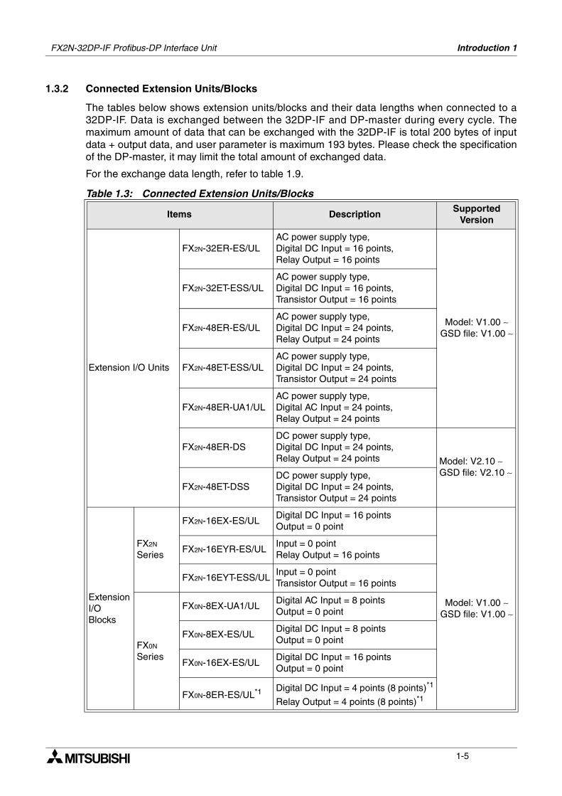
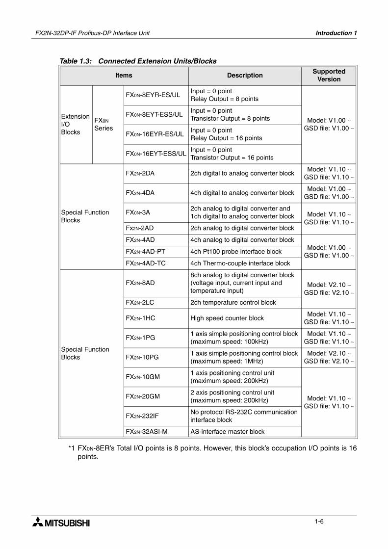
1.3.2 Connected Extension Units/Blocks
The tables below shows extension units/blocks and their data lengths when connected to a32DP-IF. Data is exchanged between the 32DP-IF and DP-master during every cycle. Themaximum amount of data that can be exchanged with the 32DP-IF is total 200 bytes of inputdata + output data, and user parameter is maximum 193 bytes. Please check the specificationof the DP-master, it may limit the total amount of exchanged data.
For the exchange data length, refer to table 1.9.
Table 1.3: Connected Extension Units/Blocks
Items DescriptionSupported
Version
Extension I/O Units
FX2N-32ER-ES/ULAC power supply type, Digital DC Input = 16 points, Relay Output = 16 points
Model: V1.00 ∼ GSD file: V1.00 ∼
FX2N-32ET-ESS/ULAC power supply type, Digital DC Input = 16 points, Transistor Output = 16 points
FX2N-48ER-ES/ULAC power supply type, Digital DC Input = 24 points, Relay Output = 24 points
FX2N-48ET-ESS/ULAC power supply type, Digital DC Input = 24 points, Transistor Output = 24 points
FX2N-48ER-UA1/ULAC power supply type, Digital AC Input = 24 points, Relay Output = 24 points
FX2N-48ER-DSDC power supply type, Digital DC Input = 24 points, Relay Output = 24 points Model: V2.10 ∼
GSD file: V2.10 ∼FX2N-48ET-DSS
DC power supply type, Digital DC Input = 24 points, Transistor Output = 24 points
Extension I/O Blocks
FX2N Series
FX2N-16EX-ES/ULDigital DC Input = 16 pointsOutput = 0 point
Model: V1.00 ∼ GSD file: V1.00 ∼
FX2N-16EYR-ES/ULInput = 0 pointRelay Output = 16 points
FX2N-16EYT-ESS/ULInput = 0 pointTransistor Output = 16 points
FX0N Series
FX0N-8EX-UA1/ULDigital AC Input = 8 pointsOutput = 0 point
FX0N-8EX-ES/ULDigital DC Input = 8 pointsOutput = 0 point
FX0N-16EX-ES/ULDigital DC Input = 16 pointsOutput = 0 point
FX0N-8ER-ES/UL*1 Digital DC Input = 4 points (8 points)*1
Relay Output = 4 points (8 points)*1
FX2N-32DP-IF Profibus-DP Interface Unit Introduction 1
1-6
*1 FX0N-8ER’s Total I/O points is 8 points. However, this block’s occupation I/O points is 16points.
Extension I/O Blocks
FX0N Series
FX0N-8EYR-ES/ULInput = 0 pointRelay Output = 8 points
Model: V1.00 ∼ GSD file: V1.00 ∼
FX0N-8EYT-ESS/ULInput = 0 pointTransistor Output = 8 points
FX0N-16EYR-ES/ULInput = 0 pointRelay Output = 16 points
FX0N-16EYT-ESS/ULInput = 0 pointTransistor Output = 16 points
Special Function Blocks
FX2N-2DA 2ch digital to analog converter blockModel: V1.10 ∼
GSD file: V1.10 ∼
FX2N-4DA 4ch digital to analog converter blockModel: V1.00 ∼
GSD file: V1.00 ∼
FX0N-3A2ch analog to digital converter and 1ch digital to analog converter block Model: V1.10 ∼
GSD file: V1.10 ∼Fx2N-2AD 2ch analog to digital converter block
FX2N-4AD 4ch analog to digital converter blockModel: V1.00 ∼
GSD file: V1.00 ∼FX2N-4AD-PT 4ch Pt100 probe interface block
FX2N-4AD-TC 4ch Thermo-couple interface block
Special Function Blocks
FX2N-8AD8ch analog to digital converter block (voltage input, current input and temperature input)
Model: V2.10 ∼ GSD file: V2.10 ∼
FX2N-2LC 2ch temperature control block
FX2N-1HC High speed counter blockModel: V1.10 ∼
GSD file: V1.10 ∼
FX2N-1PG1 axis simple positioning control block (maximum speed: 100kHz)
Model: V1.10 ∼ GSD file: V1.10 ∼
FX2N-10PG1 axis simple positioning control block (maximum speed: 1MHz)
Model: V2.10 ∼ GSD file: V2.10 ∼
FX2N-10GM1 axis positioning control unit (maximum speed: 200kHz)
Model: V1.10 ∼ GSD file: V1.10 ∼
FX2N-20GM2 axis positioning control unit (maximum speed: 200kHz)
FX2N-232IFNo protocol RS-232C communication interface block
FX2N-32ASI-M AS-interface master block
Table 1.3: Connected Extension Units/Blocks
Items DescriptionSupported
Version
FX2N-32DP-IF Profibus-DP Interface Unit Introduction 1
1-7
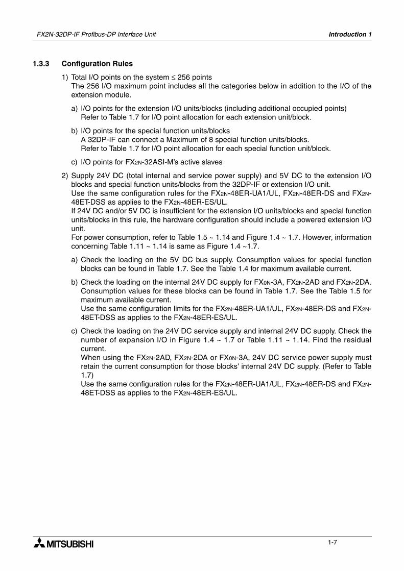
1.3.3 Configuration Rules
1) Total I/O points on the system ≤ 256 pointsThe 256 I/O maximum point includes all the categories below in addition to the I/O of theextension module.
a) I/O points for the extension I/O units/blocks (including additional occupied points)Refer to Table 1.7 for I/O point allocation for each extension unit/block.
b) I/O points for the special function units/blocksA 32DP-IF can connect a Maximum of 8 special function units/blocks. Refer to Table 1.7 for I/O point allocation for each special function unit/block.
c) I/O points for FX2N-32ASI-M’s active slaves
2) Supply 24V DC (total internal and service power supply) and 5V DC to the extension I/Oblocks and special function units/blocks from the 32DP-IF or extension I/O unit.Use the same configuration rules for the FX2N-48ER-UA1/UL, FX2N-48ER-DS and FX2N-48ET-DSS as applies to the FX2N-48ER-ES/UL.If 24V DC and/or 5V DC is insufficient for the extension I/O units/blocks and special functionunits/blocks in this rule, the hardware configuration should include a powered extension I/Ounit. For power consumption, refer to Table 1.5 ~ 1.14 and Figure 1.4 ~ 1.7. However, informationconcerning Table 1.11 ~ 1.14 is same as Figure 1.4 ~1.7.
a) Check the loading on the 5V DC bus supply. Consumption values for special functionblocks can be found in Table 1.7. See the Table 1.4 for maximum available current.
b) Check the loading on the internal 24V DC supply for FX0N-3A, FX2N-2AD and FX2N-2DA.Consumption values for these blocks can be found in Table 1.7. See the Table 1.5 formaximum available current.Use the same configuration limits for the FX2N-48ER-UA1/UL, FX2N-48ER-DS and FX2N-48ET-DSS as applies to the FX2N-48ER-ES/UL.
c) Check the loading on the 24V DC service supply and internal 24V DC supply. Check thenumber of expansion I/O in Figure 1.4 ~ 1.7 or Table 1.11 ~ 1.14. Find the residualcurrent. When using the FX2N-2AD, FX2N-2DA or FX0N-3A, 24V DC service power supply mustretain the current consumption for those blocks' internal 24V DC supply. (Refer to Table1.7)Use the same configuration rules for the FX2N-48ER-UA1/UL, FX2N-48ER-DS and FX2N-48ET-DSS as applies to the FX2N-48ER-ES/UL.
FX2N-32DP-IF Profibus-DP Interface Unit Introduction 1
1-8
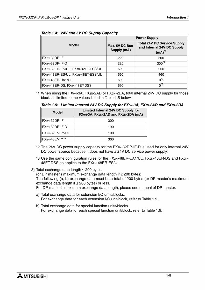
*1 When using the FX0N-3A, FX2N-2AD or FX2N-2DA, total internal 24V DC supply for thoseblocks is limited to the values listed in Table 1.5 below.
*2 The 24V DC power supply capacity for the FX2N-32DP-IF-D is used for only internal 24VDC power source because it does not have a 24V DC service power supply.
*3 Use the same configuration rules for the FX2N-48ER-UA1/UL, FX2N-48ER-DS and FX2N-48ET-DSS as applies to the FX2N-48ER-ES/UL.
3) Total exchange data length ≤ 200 bytes (or DP master’s maximum exchange data length if ≤ 200 bytes)The following (a, b) exchange data must be a total of 200 bytes (or DP master’s maximumexchange data length if ≤ 200 bytes) or less.For DP-master’s maximum exchange data length, please see manual of DP-master.
a) Total exchange data for extension I/O units/blocks.For exchange data for each extension I/O unit/block, refer to Table 1.9.
b) Total exchange data for special function units/blocks.For exchange data for each special function unit/block, refer to Table 1.9.
Table 1.4: 24V and 5V DC Supply Capacity
Model
Power Supply
Max. 5V DC Bus Supply (mA)
Total 24V DC Service Supply and Internal 24V DC Supply
(mA)*1
FX2N-32DP-IF 220 500
FX2N-32DP-IF-D 220 300*2
FX2N-32ER-ES/UL, FX2N-32ET-ESS/UL 690 250
FX2N-48ER-ES/UL, FX2N-48ET-ESS/UL 690 460
FX2N-48ER-UA1/UL 690 0*3
FX2N-48ER-DS, FX2N-48ET-DSS 690 0*3
Table 1.5: Limited Internal 24V DC Supply for FX0N-3A, FX2N-2AD and FX2N-2DA
ModelLimited Internal 24V DC Supply for
FX0N-3A, FX2N-2AD and FX2N-2DA (mA)
FX2N-32DP-IF 300
FX2N-32DP-IF-D 190
FX2N-32E*-E**/UL 190
FX2N-48E*-***** 300
FX2N-32DP-IF Profibus-DP Interface Unit Introduction 1
1-9
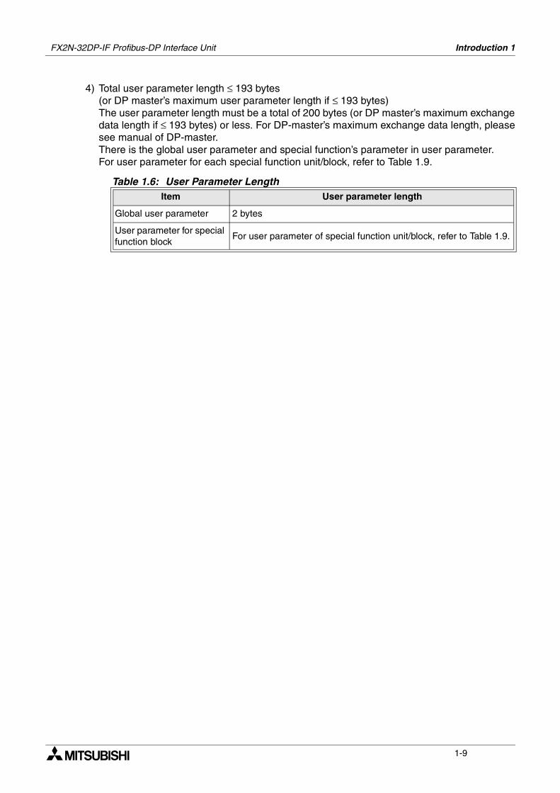
4) Total user parameter length ≤ 193 bytes (or DP master’s maximum user parameter length if ≤ 193 bytes)The user parameter length must be a total of 200 bytes (or DP master’s maximum exchangedata length if ≤ 193 bytes) or less. For DP-master’s maximum exchange data length, pleasesee manual of DP-master.There is the global user parameter and special function’s parameter in user parameter.For user parameter for each special function unit/block, refer to Table 1.9.
Table 1.6: User Parameter LengthItem User parameter length
Global user parameter 2 bytes
User parameter for special function block
For user parameter of special function unit/block, refer to Table 1.9.
FX2N-32DP-IF Profibus-DP Interface Unit Introduction 1
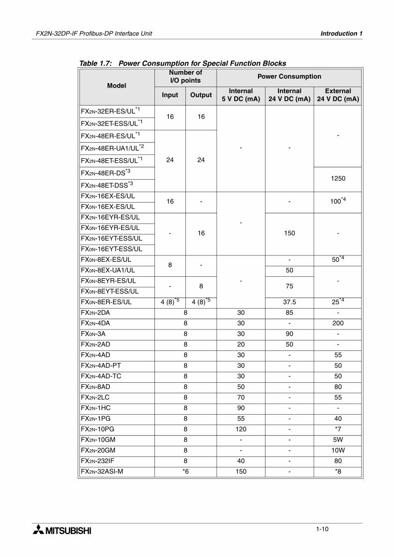
1-10
Table 1.7: Power Consumption for Special Function Blocks
Model
Number of I/O points
Power Consumption
Input OutputInternal
5 V DC (mA)Internal
24 V DC (mA)External
24 V DC (mA)
FX2N-32ER-ES/UL*1
16 16
- -
-
FX2N-32ET-ESS/UL*1
FX2N-48ER-ES/UL*1
24 24
FX2N-48ER-UA1/UL*2
FX2N-48ET-ESS/UL*1
FX2N-48ER-DS*3
1250FX2N-48ET-DSS*3
FX2N-16EX-ES/UL16 -
-
- 100*4
FX0N-16EX-ES/UL
FX2N-16EYR-ES/UL
- 16 150 -FX0N-16EYR-ES/UL
FX2N-16EYT-ESS/UL
FX0N-16EYT-ESS/UL
FX0N-8EX-ES/UL8 -
-
- 50*4
FX0N-8EX-UA1/UL 50
-FX0N-8EYR-ES/UL- 8 75
FX0N-8EYT-ESS/UL
FX0N-8ER-ES/UL 4 (8)*5 4 (8)*5 37.5 25*4
FX2N-2DA 8 30 85 -
FX2N-4DA 8 30 - 200
FX0N-3A 8 30 90 -
FX2N-2AD 8 20 50 -
FX2N-4AD 8 30 - 55
FX2N-4AD-PT 8 30 - 50
FX2N-4AD-TC 8 30 - 50
FX2N-8AD 8 50 - 80
FX2N-2LC 8 70 - 55
FX2N-1HC 8 90 - -
FX2N-1PG 8 55 - 40
FX2N-10PG 8 120 - *7
FX2N-10GM 8 - - 5W
FX2N-20GM 8 - - 10W
FX2N-232IF 8 40 - 80
FX2N-32ASI-M *6 150 - *8
FX2N-32DP-IF Profibus-DP Interface Unit Introduction 1
1-11
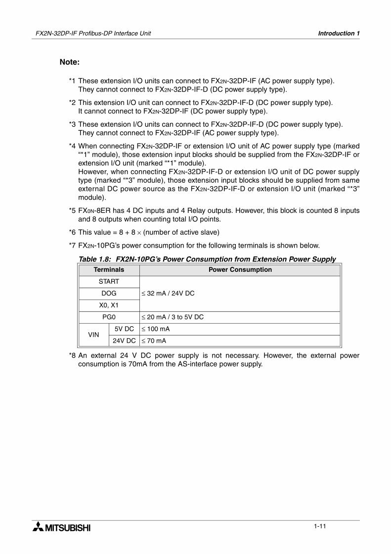
Note:
*1 These extension I/O units can connect to FX2N-32DP-IF (AC power supply type).They cannot connect to FX2N-32DP-IF-D (DC power supply type).
*2 This extension I/O unit can connect to FX2N-32DP-IF-D (DC power supply type).It cannot connect to FX2N-32DP-IF (DC power supply type).
*3 These extension I/O units can connect to FX2N-32DP-IF-D (DC power supply type).They cannot connect to FX2N-32DP-IF (AC power supply type).
*4 When connecting FX2N-32DP-IF or extension I/O unit of AC power supply type (marked“*1” module), those extension input blocks should be supplied from the FX2N-32DP-IF orextension I/O unit (marked “*1” module).However, when connecting FX2N-32DP-IF-D or extension I/O unit of DC power supplytype (marked “*3” module), those extension input blocks should be supplied from sameexternal DC power source as the FX2N-32DP-IF-D or extension I/O unit (marked “*3”module).
*5 FX0N-8ER has 4 DC inputs and 4 Relay outputs. However, this block is counted 8 inputsand 8 outputs when counting total I/O points.
*6 This value = 8 + 8 × (number of active slave)
*7 FX2N-10PG’s power consumption for the following terminals is shown below.
*8 An external 24 V DC power supply is not necessary. However, the external powerconsumption is 70mA from the AS-interface power supply.
Table 1.8: FX2N-10PG’s Power Consumption from Extension Power SupplyTerminals Power Consumption
START
≤ 32 mA / 24V DCDOG
X0, X1
PG0 ≤ 20 mA / 3 to 5V DC
VIN5V DC ≤ 100 mA
24V DC ≤ 70 mA
FX2N-32DP-IF Profibus-DP Interface Unit Introduction 1
1-12
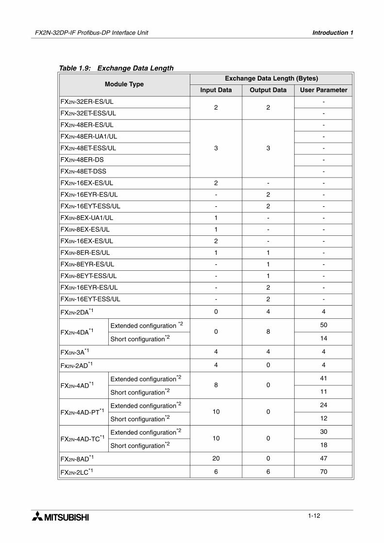
Table 1.9: Exchange Data Length
Module TypeExchange Data Length (Bytes)
Input Data Output Data User Parameter
FX2N-32ER-ES/UL2 2
-
FX2N-32ET-ESS/UL -
FX2N-48ER-ES/UL
3 3
-
FX2N-48ER-UA1/UL -
FX2N-48ET-ESS/UL -
FX2N-48ER-DS -
FX2N-48ET-DSS -
FX2N-16EX-ES/UL 2 - -
FX2N-16EYR-ES/UL - 2 -
FX2N-16EYT-ESS/UL - 2 -
FX0N-8EX-UA1/UL 1 - -
FX0N-8EX-ES/UL 1 - -
FX0N-16EX-ES/UL 2 - -
FX0N-8ER-ES/UL 1 1 -
FX0N-8EYR-ES/UL - 1 -
FX0N-8EYT-ESS/UL - 1 -
FX0N-16EYR-ES/UL - 2 -
FX0N-16EYT-ESS/UL - 2 -
FX2N-2DA*1 0 4 4
FX2N-4DA*1Extended configuration *2
0 850
Short configuration*2 14
FX0N-3A*1 4 4 4
Fx2N-2AD*1 4 0 4
FX2N-4AD*1Extended configuration*2
8 041
Short configuration*2 11
FX2N-4AD-PT*1Extended configuration*2
10 024
Short configuration*2 12
FX2N-4AD-TC*1Extended configuration*2
10 030
Short configuration*2 18
FX2N-8AD*1 20 0 47
FX2N-2LC*1 6 6 70
FX2N-32DP-IF Profibus-DP Interface Unit Introduction 1
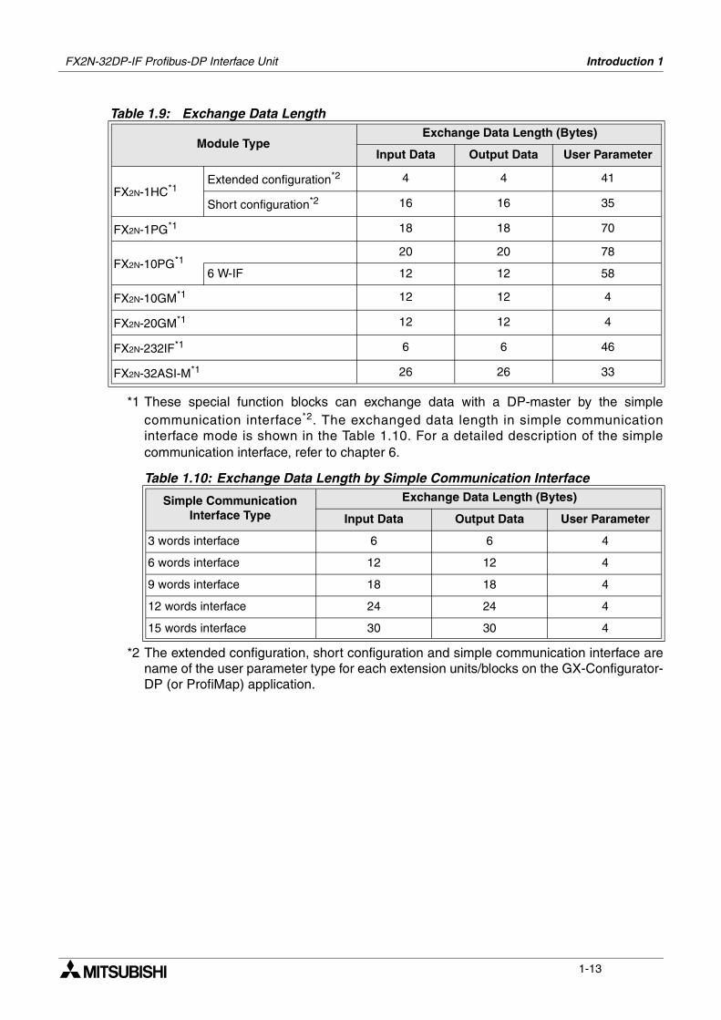
1-13
*1 These special function blocks can exchange data with a DP-master by the simplecommunication interface*2. The exchanged data length in simple communicationinterface mode is shown in the Table 1.10. For a detailed description of the simplecommunication interface, refer to chapter 6.
*2 The extended configuration, short configuration and simple communication interface arename of the user parameter type for each extension units/blocks on the GX-Configurator-DP (or ProfiMap) application.
FX2N-1HC*1Extended configuration*2 4 4 41
Short configuration*2 16 16 35
FX2N-1PG*1 18 18 70
FX2N-10PG*120 20 78
6 W-IF 12 12 58
FX2N-10GM*1 12 12 4
FX2N-20GM*1 12 12 4
FX2N-232IF*1 6 6 46
FX2N-32ASI-M*1 26 26 33
Table 1.10: Exchange Data Length by Simple Communication Interface
Simple Communication Interface Type
Exchange Data Length (Bytes)
Input Data Output Data User Parameter
3 words interface 6 6 4
6 words interface 12 12 4
9 words interface 18 18 4
12 words interface 24 24 4
15 words interface 30 30 4
Table 1.9: Exchange Data Length
Module TypeExchange Data Length (Bytes)
Input Data Output Data User Parameter
FX2N-32DP-IF Profibus-DP Interface Unit Introduction 1
1-14
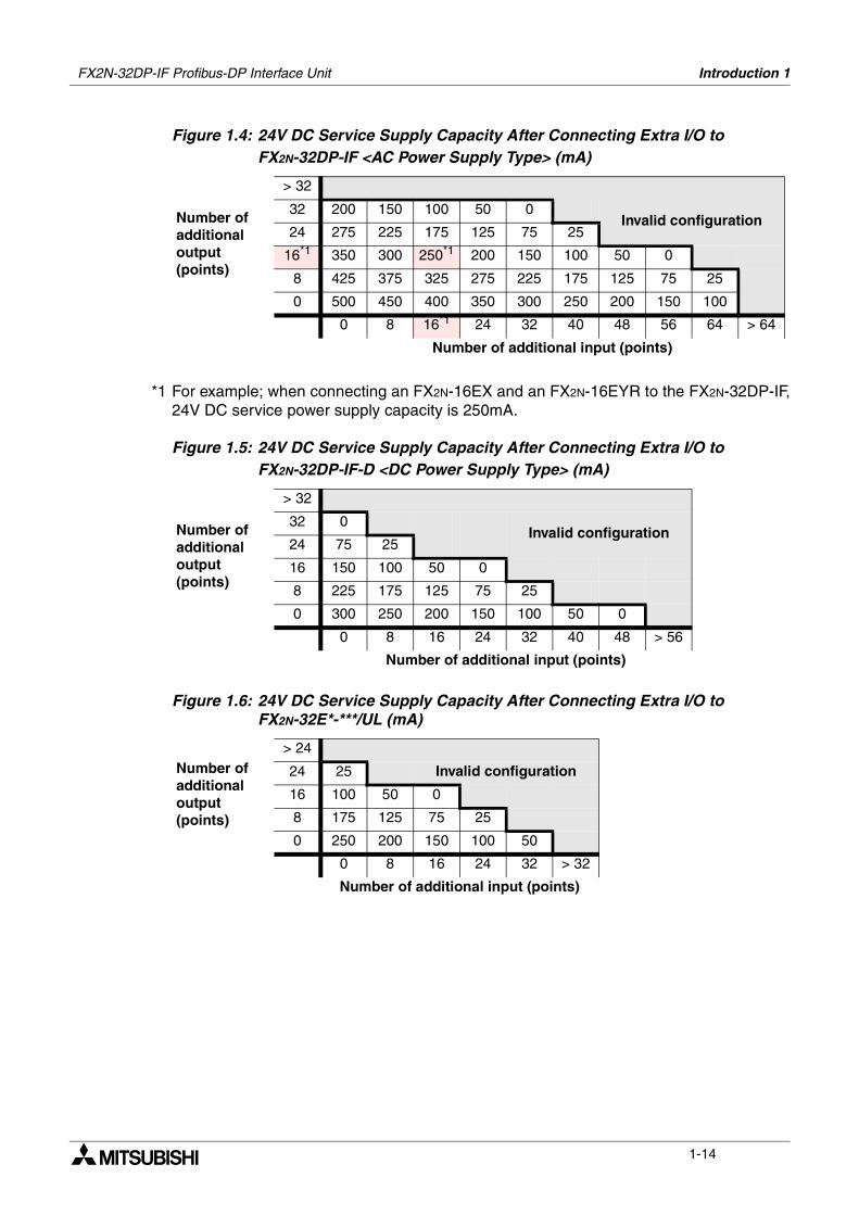
Figure 1.4: 24V DC Service Supply Capacity After Connecting Extra I/O to FX2N-32DP-IF <AC Power Supply Type> (mA)
*1 For example; when connecting an FX2N-16EX and an FX2N-16EYR to the FX2N-32DP-IF,24V DC service power supply capacity is 250mA.
Figure 1.5: 24V DC Service Supply Capacity After Connecting Extra I/O to FX2N-32DP-IF-D <DC Power Supply Type> (mA)
Figure 1.6: 24V DC Service Supply Capacity After Connecting Extra I/O to FX2N-32E*-***/UL (mA)
Number of additional output (points)
> 32
32 200 150 100 50 0Invalid configuration
24 275 225 175 125 75 25
16*1 350 300 250*1 200 150 100 50 0
8 425 375 325 275 225 175 125 75 25
0 500 450 400 350 300 250 200 150 100
0 8 16*1 24 32 40 48 56 64 > 64
Number of additional input (points)
Number of additional output (points)
> 32
32 0Invalid configuration
24 75 25
16 150 100 50 0
8 225 175 125 75 25
0 300 250 200 150 100 50 0
0 8 16 24 32 40 48 > 56
Number of additional input (points)
Number of additional output (points)
> 24
24 25 Invalid configuration
16 100 50 0
8 175 125 75 25
0 250 200 150 100 50
0 8 16 24 32 > 32
Number of additional input (points)
FX2N-32DP-IF Profibus-DP Interface Unit Introduction 1
1-15
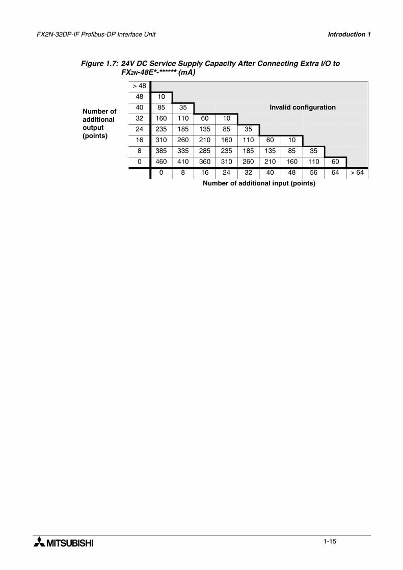
Figure 1.7: 24V DC Service Supply Capacity After Connecting Extra I/O to FX2N-48E*-****** (mA)
Number of additional output (points)
> 48
48 10
40 85 35 Invalid configuration
32 160 110 60 10
24 235 185 135 85 35
16 310 260 210 160 110 60 10
8 385 335 285 235 185 135 85 35
0 460 410 360 310 260 210 160 110 60
0 8 16 24 32 40 48 56 64 > 64
Number of additional input (points)
FX2N-32DP-IF Profibus-DP Interface Unit Introduction 1
1-16
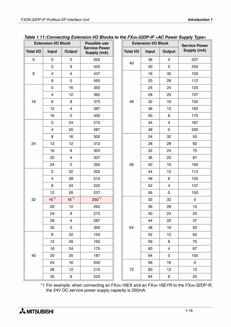
*1 For example; when connecting an FX2N-16EX and an FX2N-16EYR to the FX2N-32DP-IF,the 24V DC service power supply capacity is 250mA.
Table 1.11:Connecting Extension I/O Blocks to the FX2N-32DP-IF <AC Power Supply Type>Extension I/O Block Possible use
Service Power Supply (mA)
Extension I/O BlockService Power Supply (mA)Total I/O Input Output Total I/O Input Output
0 0 0 50040
36 4 237
8
0 8 425 40 0 250
4 4 437
48
16 32 100
8 0 450 20 28 112
16
0 16 350 24 24 125
4 12 362 28 20 137
8 8 375 32 16 150
12 4 387 36 12 162
16 0 400 40 8 175
24
0 24 275 44 4 187
4 20 287 48 0 200
8 16 300
56
24 32 50
12 12 312 28 28 62
16 8 325 32 24 75
20 4 337 36 20 87
24 0 350 40 16 100
32
0 32 200 44 12 112
4 28 212 48 8 125
8 24 225 52 4 137
12 20 237 56 0 150
16*1 16*1 250*1
64
32 32 0
20 12 262 36 28 12
24 8 275 40 24 25
28 4 287 44 20 37
32 0 300 48 16 50
40
8 32 150 52 12 62
12 28 162 56 8 75
16 24 175 60 4 87
20 20 187 64 0 100
24 16 200
72
56 16 0
28 12 212 60 12 12
32 8 225 64 8 25
FX2N-32DP-IF Profibus-DP Interface Unit Introduction 1
1-17
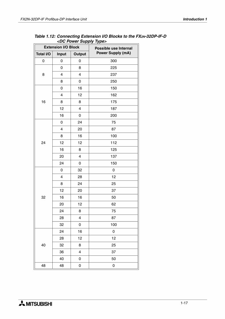
Table 1.12: Connecting Extension I/O Blocks to the FX2N-32DP-IF-D <DC Power Supply Type>
Extension I/O Block Possible use Internal Power Supply (mA)Total I/O Input Output
0 0 0 300
8
0 8 225
4 4 237
8 0 250
16
0 16 150
4 12 162
8 8 175
12 4 187
16 0 200
24
0 24 75
4 20 87
8 16 100
12 12 112
16 8 125
20 4 137
24 0 150
32
0 32 0
4 28 12
8 24 25
12 20 37
16 16 50
20 12 62
24 8 75
28 4 87
32 0 100
40
24 16 0
28 12 12
32 8 25
36 4 37
40 0 50
48 48 0 0
FX2N-32DP-IF Profibus-DP Interface Unit Introduction 1
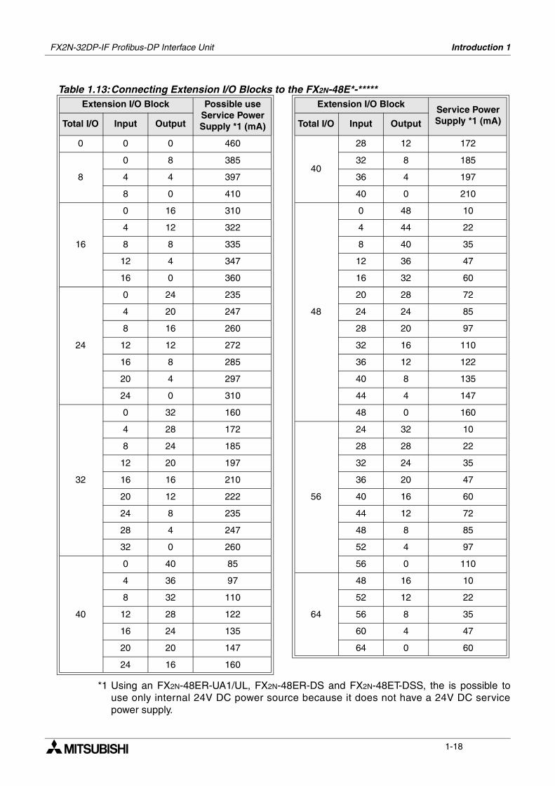
1-18
*1 Using an FX2N-48ER-UA1/UL, FX2N-48ER-DS and FX2N-48ET-DSS, the is possible touse only internal 24V DC power source because it does not have a 24V DC servicepower supply.
Table 1.13:Connecting Extension I/O Blocks to the FX2N-48E*-*****Extension I/O Block Possible use
Service Power Supply *1 (mA)
Extension I/O BlockService Power Supply *1 (mA)Total I/O Input Output Total I/O Input Output
0 0 0 460
40
28 12 172
8
0 8 385 32 8 185
4 4 397 36 4 197
8 0 410 40 0 210
16
0 16 310
48
0 48 10
4 12 322 4 44 22
8 8 335 8 40 35
12 4 347 12 36 47
16 0 360 16 32 60
24
0 24 235 20 28 72
4 20 247 24 24 85
8 16 260 28 20 97
12 12 272 32 16 110
16 8 285 36 12 122
20 4 297 40 8 135
24 0 310 44 4 147
32
0 32 160 48 0 160
4 28 172
56
24 32 10
8 24 185 28 28 22
12 20 197 32 24 35
16 16 210 36 20 47
20 12 222 40 16 60
24 8 235 44 12 72
28 4 247 48 8 85
32 0 260 52 4 97
40
0 40 85 56 0 110
4 36 97
64
48 16 10
8 32 110 52 12 22
12 28 122 56 8 35
16 24 135 60 4 47
20 20 147 64 0 60
24 16 160
FX2N-32DP-IF Profibus-DP Interface Unit Introduction 1
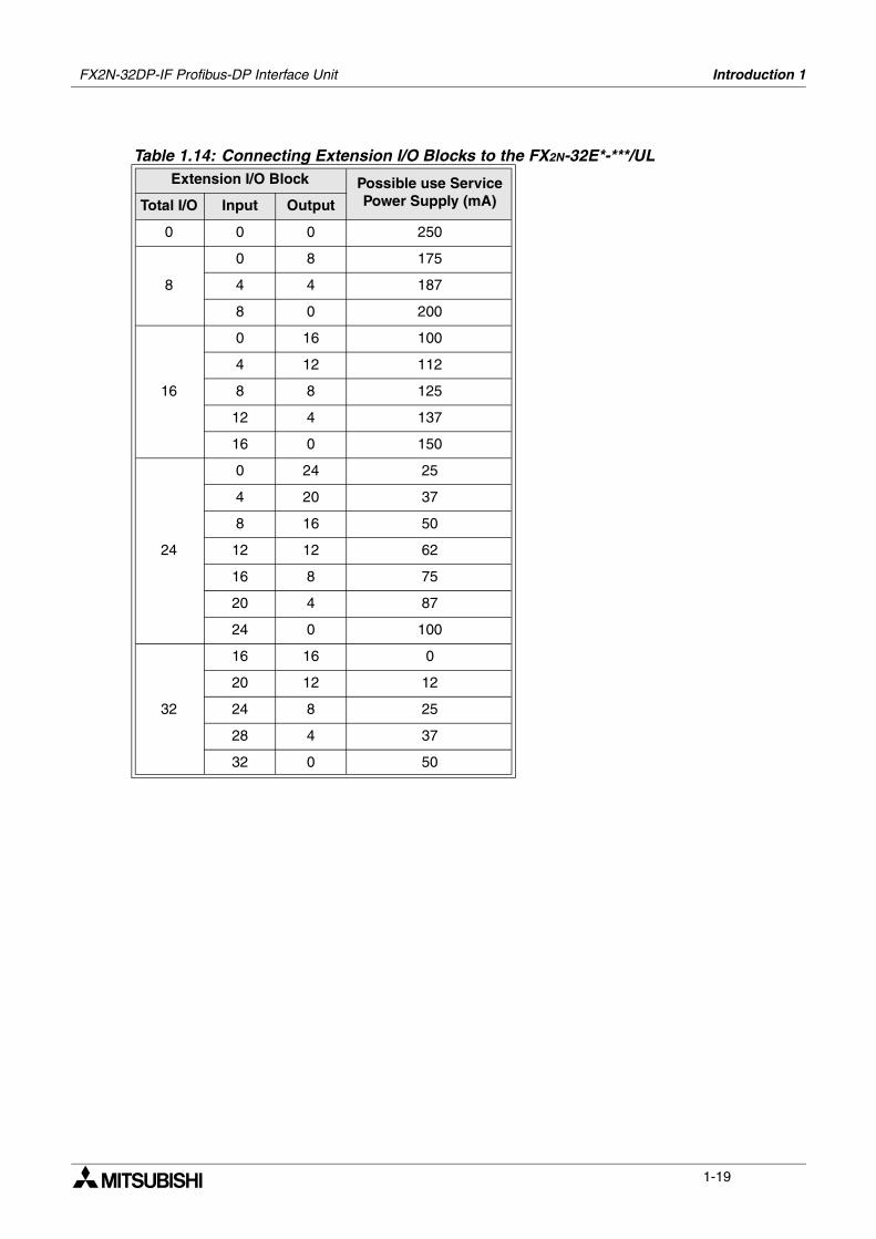
1-19
Table 1.14: Connecting Extension I/O Blocks to the FX2N-32E*-***/ULExtension I/O Block Possible use Service
Power Supply (mA)Total I/O Input Output
0 0 0 250
8
0 8 175
4 4 187
8 0 200
16
0 16 100
4 12 112
8 8 125
12 4 137
16 0 150
24
0 24 25
4 20 37
8 16 50
12 12 62
16 8 75
20 4 87
24 0 100
32
16 16 0
20 12 12
24 8 25
28 4 37
32 0 50
FX2N-32DP-IF Profibus-DP Interface Unit Introduction 1
1-20
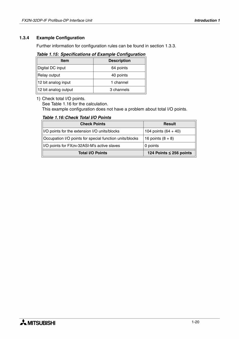
1.3.4 Example Configuration
Further information for configuration rules can be found in section 1.3.3.
1) Check total I/O points.See Table 1.16 for the calculation. This example configuration does not have a problem about total I/O points.
Table 1.15: Specifications of Example ConfigurationItem Description
Digital DC input 64 points
Relay output 40 points
12 bit analog input 1 channel
12 bit analog output 3 channels
Table 1.16:Check Total I/O PointsCheck Points Result
I/O points for the extension I/O units/blocks 104 points (64 + 40)
Occupation I/O points for special function units/blocks 16 points (8 + 8)
I/O points for FX2N-32ASI-M’s active slaves 0 points
Total I/O Points 124 Points ≤≤≤≤ 256 points
FX2N-32DP-IF Profibus-DP Interface Unit Introduction 1
1-21
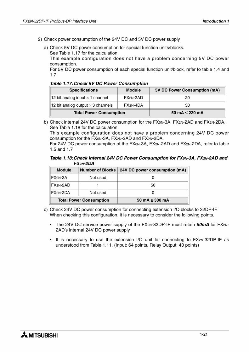
2) Check power consumption of the 24V DC and 5V DC power supply
a) Check 5V DC power consumption for special function units/blocks.See Table 1.17 for the calculation. This example configuration does not have a problem concerning 5V DC powerconsumption. For 5V DC power consumption of each special function unit/block, refer to table 1.4 and1.7
b) Check internal 24V DC power consumption for the FX0N-3A, FX2N-2AD and FX2N-2DA.See Table 1.18 for the calculation. This example configuration does not have a problem concerning 24V DC powerconsumption for the FX0N-3A, FX2N-2AD and FX2N-2DA.For 24V DC power consumption of the FX0N-3A, FX2N-2AD and FX2N-2DA, refer to table1.5 and 1.7
c) Check 24V DC power consumption for connecting extension I/O blocks to 32DP-IF.When checking this configuration, it is necessary to consider the following points.
• The 24V DC service power supply of the FX2N-32DP-IF must retain 50mA for FX2N-2AD’s internal 24V DC power supply.
• It is necessary to use the extension I/O unit for connecting to FX2N-32DP-IF asunderstood from Table 1.11. (Input: 64 points, Relay Output: 40 points)
Table 1.17:Check 5V DC Power ConsumptionSpecifications Module 5V DC Power Consumption (mA)
12 bit analog input × 1 channel FX2N-2AD 20
12 bit analog output × 3 channels FX2N-4DA 30
Total Power Consumption 50 mA ≤≤≤≤ 220 mA
Table 1.18:Check Internal 24V DC Power Consumption for FX0N-3A, FX2N-2AD and FX2N-2DA
Module Number of Blocks 24V DC power consumption (mA)
FX0N-3A Not used 0
FX2N-2AD 1 50
FX2N-2DA Not used 0
Total Power Consumption 50 mA ≤≤≤≤ 300 mA
FX2N-32DP-IF Profibus-DP Interface Unit Introduction 1
1-22
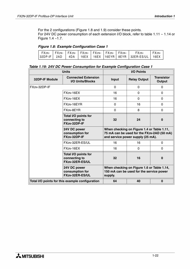
For the 2 configurations (Figure 1.8 and 1.9) consider these points. For 24V DC power consumption of each extension I/O block, refer to table 1.11 ~ 1.14 orFigure 1.4 ~1.7.
Figure 1.8: Example Configuration Case 1
Table 1.19: 24V DC Power Consumption for Example Configuration Case 1Units I/O Points
32DP-IF ModuleConnected Extension
I/O Units/BlocksInput Relay Output
Transistor Output
FX2N-32DP-IF 0 0 0
FX2N-16EX 16 0 0
FX2N-16EX 16 0 0
FX2N-16EYR 0 16 0
FX0N-8EYR 0 8 0
Total I/O points for connecting to FX2N-32DP-IF
32 24 0
24V DC power consumption for FX2N-32DP-IF
When checking on Figure 1.4 or Table 1.11, 75 mA can be used for the FX2N-2AD (50 mA) and service power supply (25 mA).
FX2N-32ER-ES/UL 16 16 0
FX2N-16EX 16 0 0
Total I/O points for connecting to FX2N-32ER-ES/UL
32 16 0
24V DC power consumption for FX2N-32ER-ES/UL
When checking on Figure 1.6 or Table 1.14, 150 mA can be used for the service power supply.
Total I/O points for this example configuration 64 40 0
FX 2N-32D P-IF
FX 2N-16EX
FX 2N-16EX
FX 2N-16EYR
FX 0N-8EYR
FX 2N-32ER-ES/U L
FX 2N-16EX
FX 2N-2AD
FX 2N-4D A
FX2N-32DP-IF Profibus-DP Interface Unit Introduction 1
1-23
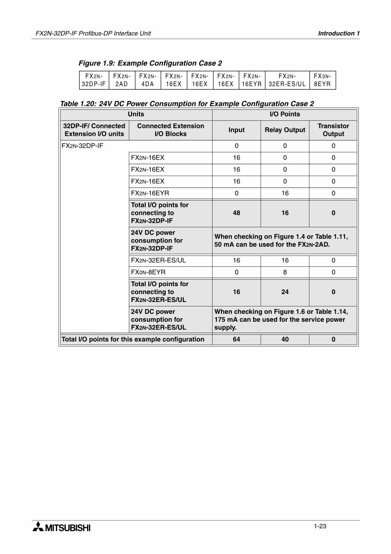
Figure 1.9: Example Configuration Case 2
Table 1.20: 24V DC Power Consumption for Example Configuration Case 2Units I/O Points
32DP-IF/ Connected Extension I/O units
Connected Extension I/O Blocks
Input Relay OutputTransistor
Output
FX2N-32DP-IF 0 0 0
FX2N-16EX 16 0 0
FX2N-16EX 16 0 0
FX2N-16EX 16 0 0
FX2N-16EYR 0 16 0
Total I/O points for connecting to FX2N-32DP-IF
48 16 0
24V DC power consumption for FX2N-32DP-IF
When checking on Figure 1.4 or Table 1.11, 50 mA can be used for the FX2N-2AD.
FX2N-32ER-ES/UL 16 16 0
FX0N-8EYR 0 8 0
Total I/O points for connecting to FX2N-32ER-ES/UL
16 24 0
24V DC power consumption for FX2N-32ER-ES/UL
When checking on Figure 1.6 or Table 1.14, 175 mA can be used for the service power supply.
Total I/O points for this example configuration 64 40 0
FX 2N-32D P-IF
FX 2N-16EX
FX 2N-16EX
FX 2N-16EYR
FX 0N-8EYR
FX 2N-32ER-ES/U L
FX 2N-16EX
FX 2N-2AD
FX 2N-4D A
FX2N-32DP-IF Profibus-DP Interface Unit Introduction 1
1-24
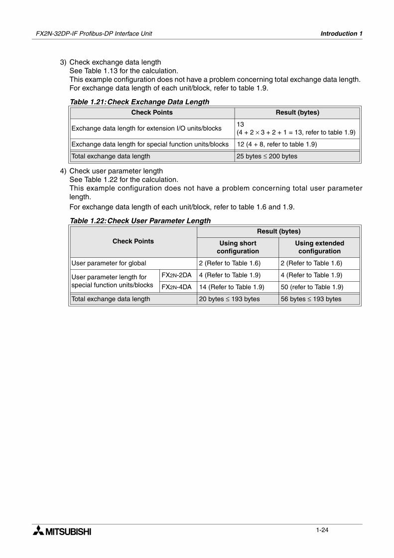
3) Check exchange data lengthSee Table 1.13 for the calculation. This example configuration does not have a problem concerning total exchange data length. For exchange data length of each unit/block, refer to table 1.9.
4) Check user parameter lengthSee Table 1.22 for the calculation. This example configuration does not have a problem concerning total user parameterlength.For exchange data length of each unit/block, refer to table 1.6 and 1.9.
Table 1.21:Check Exchange Data LengthCheck Points Result (bytes)
Exchange data length for extension I/O units/blocks13 (4 + 2 × 3 + 2 + 1 = 13, refer to table 1.9)
Exchange data length for special function units/blocks 12 (4 + 8, refer to table 1.9)
Total exchange data length 25 bytes ≤ 200 bytes
Table 1.22:Check User Parameter Length
Check Points
Result (bytes)
Using short configuration
Using extended configuration
User parameter for global 2 (Refer to Table 1.6) 2 (Refer to Table 1.6)
User parameter length for special function units/blocks
FX2N-2DA 4 (Refer to Table 1.9) 4 (Refer to Table 1.9)
FX2N-4DA 14 (Refer to Table 1.9) 50 (refer to Table 1.9)
Total exchange data length 20 bytes ≤ 193 bytes 56 bytes ≤ 193 bytes
Mounting 2
2-1
2. Mounting
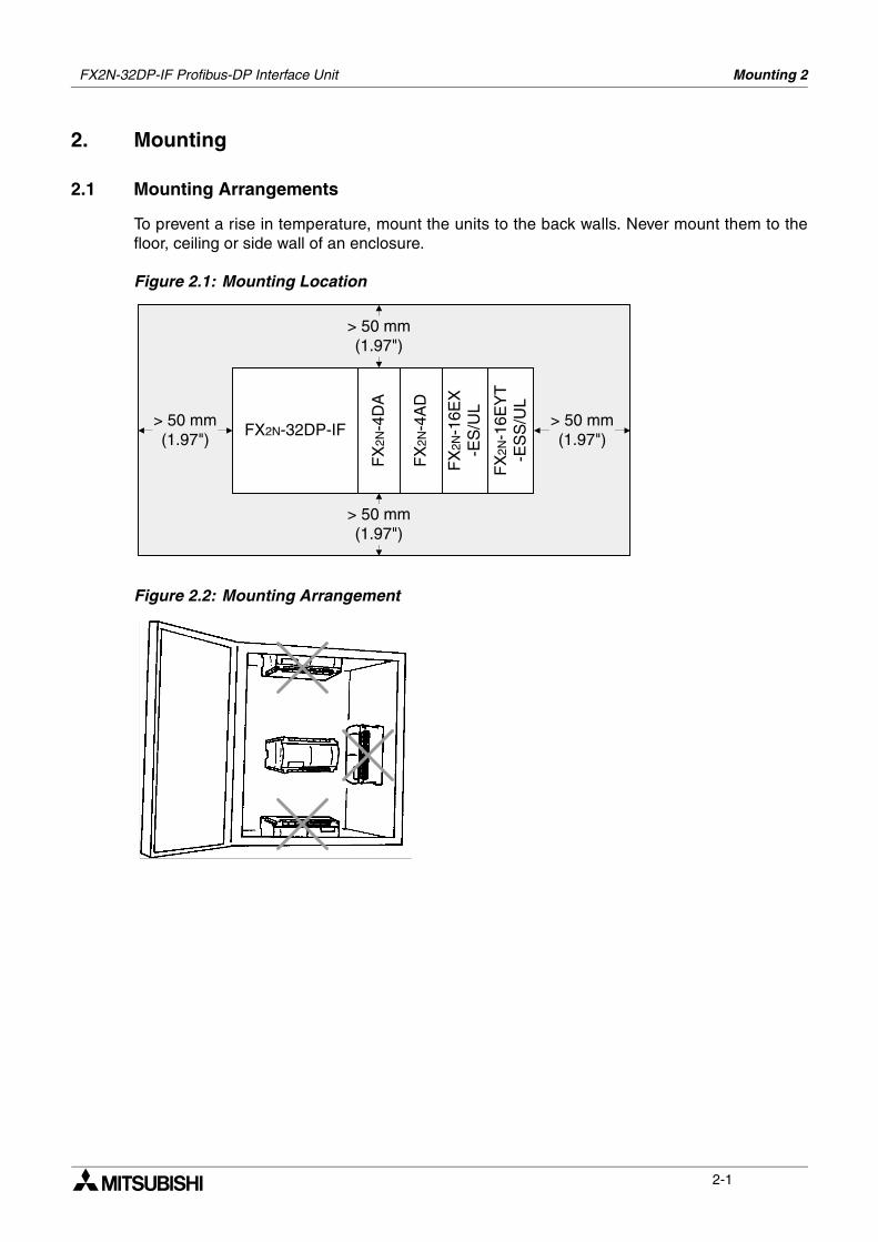
2.1 Mounting Arrangements
To prevent a rise in temperature, mount the units to the back walls. Never mount them to thefloor, ceiling or side wall of an enclosure.
Figure 2.1: Mounting Location
Figure 2.2: Mounting Arrangement
> 50 mm(1.97")
FX2N-32DP-IF
FX
2N-4
DA
FX
2N-4
AD
FX
2N-1
6EX
-ES
/UL
FX
2N-1
6EY
T-E
SS
/UL
> 50 mm(1.97")
> 50 mm(1.97")
> 50 mm(1.97")
FX2N-32DP-IF Profibus-DP Interface Unit
FX2N-32DP-IF Profibus-DP Interface Unit Mounting 2
2-2
2.2 Mounting
Mounting method for the 32DP-IF is DIN rail mounting or direct wall mounting.
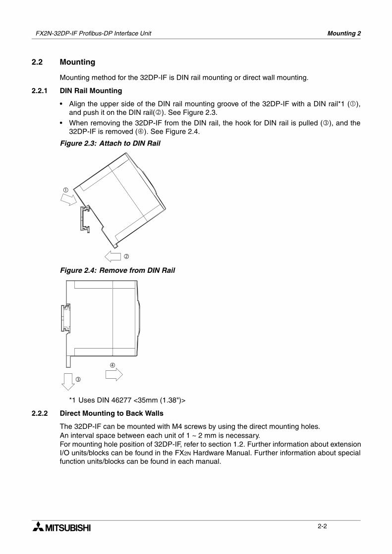
2.2.1 DIN Rail Mounting
• Align the upper side of the DIN rail mounting groove of the 32DP-IF with a DIN rail*1 (),and push it on the DIN rail(). See Figure 2.3.
• When removing the 32DP-IF from the DIN rail, the hook for DIN rail is pulled (), and the32DP-IF is removed (). See Figure 2.4.
Figure 2.3: Attach to DIN Rail
Figure 2.4: Remove from DIN Rail
*1 Uses DIN 46277 <35mm (1.38")>
2.2.2 Direct Mounting to Back Walls
The 32DP-IF can be mounted with M4 screws by using the direct mounting holes. An interval space between each unit of 1 ~ 2 mm is necessary.For mounting hole position of 32DP-IF, refer to section 1.2. Further information about extensionI/O units/blocks can be found in the FX2N Hardware Manual. Further information about specialfunction units/blocks can be found in each manual.
Wiring 3
3-1
3. Wiring
3.1 Caution for Wiring
1) Do not lay signal cable near to either high voltage power cabling or cabinet housing alongthe same trunking duct. Effects of noise or surge induction may occur. Keep signal cables ofmore than 100 mm (3.94") from these power cables.
2) Ground the shield wire or the shield of a cable at one point on the module. Do not, however,ground at the same point as high voltage lines.
3) Cut off all phases of power source before installation or performing wiring work in order toavoid electric shock or damage to the product.
4) Replace the provided terminal cover before supplying power and operating the unit afterinstallation or wiring work, in order to avoid electric shock.
5) To connect the 32DP-IF to a Profibus-DP network should be used only the Profibusconnectors and shielded twisted-pair cable complying with EN50170.
6) The power supply of the extension units/blocks and the special function units/blocks shouldbe starting-up at the same time or earlier than it with 32DP-IF.
7) DO NOT use “” terminal in 32DP-IF.
8) “24+” and “24-” terminal are not reversible.If “24+” and “24-” terminal are reversed, the units/block may be serious damaged.
9) The terminal tightening torque is 0.5 to 0.8 N•m. Tighten securely to avoid malfunction.
FX2N-32DP-IF Profibus-DP Interface Unit
FX2N-32DP-IF Profibus-DP Interface Unit Wiring 3
3-2
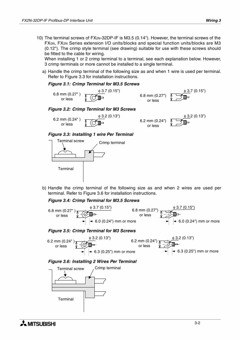
10) The terminal screws of FX2N-32DP-IF is M3.5 (0.14"). However, the terminal screws of theFX0N, FX2N Series extension I/O units/blocks and special function units/blocks are M3(0.12"). The crimp style terminal (see drawing) suitable for use with these screws shouldbe fitted to the cable for wiring. When installing 1 or 2 crimp terminal to a terminal, see each explanation below. However,3 crimp terminals or more cannot be installed to a single terminal.
a) Handle the crimp terminal of the following size as and when 1 wire is used per terminal.Refer to Figure 3.3 for installation instructions.
Figure 3.1: Crimp Terminal for M3.5 Screws
Figure 3.2: Crimp Terminal for M3 Screws
Figure 3.3: Installing 1 wire Per Terminal
b) Handle the crimp terminal of the following size as and when 2 wires are used perterminal. Refer to Figure 3.6 for installation instructions.
Figure 3.4: Crimp Terminal for M3.5 Screws
Figure 3.5: Crimp Terminal for M3 Screws
Figure 3.6: Installing 2 Wires Per Terminal
6.8 mm (0.27" )or less
φ 3.7 (0.15")6.8 mm (0.27")
or less
φ 3.7 (0.15")
6.2 mm (0.24" )or less
φ 3.2 (0.13")6.2 mm (0.24")
or less
φ 3.2 (0.13")
Crimp terminal
Terminal
Terminal screw
6.8 mm (0.27" )or less
φ 3.7 (0.15")6.8 mm (0.27")
or less
φ 3.7 (0.15")
6.0 (0.24") mm or more 6.0 (0.24") mm or more
6.2 mm (0.24" )or less
φ 3.2 (0.13")6.2 mm (0.24")
or less
φ 3.2 (0.13")
6.3 (0.25") mm or more 6.3 (0.25") mm or more
Crimp terminal
Terminal
Terminal screw
FX2N-32DP-IF Profibus-DP Interface Unit Wiring 3
3-3
3.2 Power Supply
Further information for the extension unit’s wiring can be found in the FX2N Series HardwareManual. Further information for special function units/blocks can be found in their respectivemanual. For wiring of grounding, refer to Section 3.3.
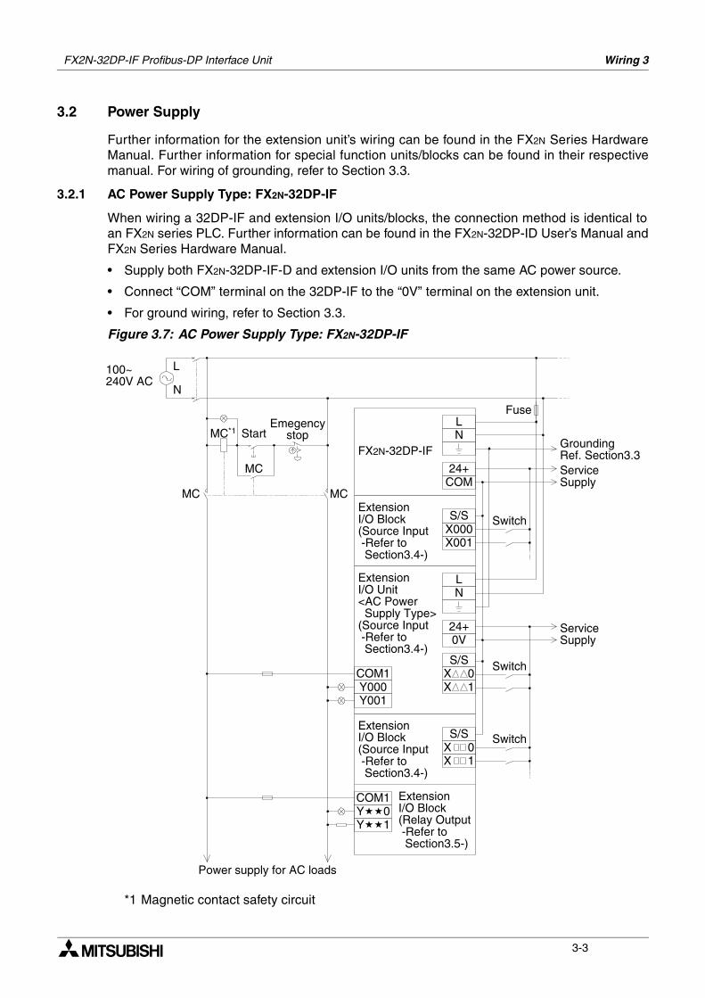
3.2.1 AC Power Supply Type: FX2N-32DP-IF
When wiring a 32DP-IF and extension I/O units/blocks, the connection method is identical toan FX2N series PLC. Further information can be found in the FX2N-32DP-ID User’s Manual andFX2N Series Hardware Manual.
• Supply both FX2N-32DP-IF-D and extension I/O units from the same AC power source.
• Connect “COM” terminal on the 32DP-IF to the “0V” terminal on the extension unit.
• For ground wiring, refer to Section 3.3.
Figure 3.7: AC Power Supply Type: FX2N-32DP-IF
*1 Magnetic contact safety circuit
100~240V AC
L
N
MC*1 Start
MC
Emegencystop
MC MCCOM24+
LN
S/SX000X001
LN
0V24+
S/SCOM1Y000Y001
S/S
COM1Y0Y1
ExtensionI/O Block(Relay Output -Refer to Section3.5-)
ExtensionI/O Block(Source Input -Refer to Section3.4-)
ExtensionI/O Unit<AC Power Supply Type>(Source Input -Refer to Section3.4-)
ExtensionI/O Block(Source Input -Refer to Section3.4-)
FX2N-32DP-IF
Power supply for AC loads
Switch
Switch
Fuse
GroundingRef. Section3.3ServiceSupply
ServiceSupply
SwitchX 0X 1
X 1X 0
FX2N-32DP-IF Profibus-DP Interface Unit Wiring 3
3-4
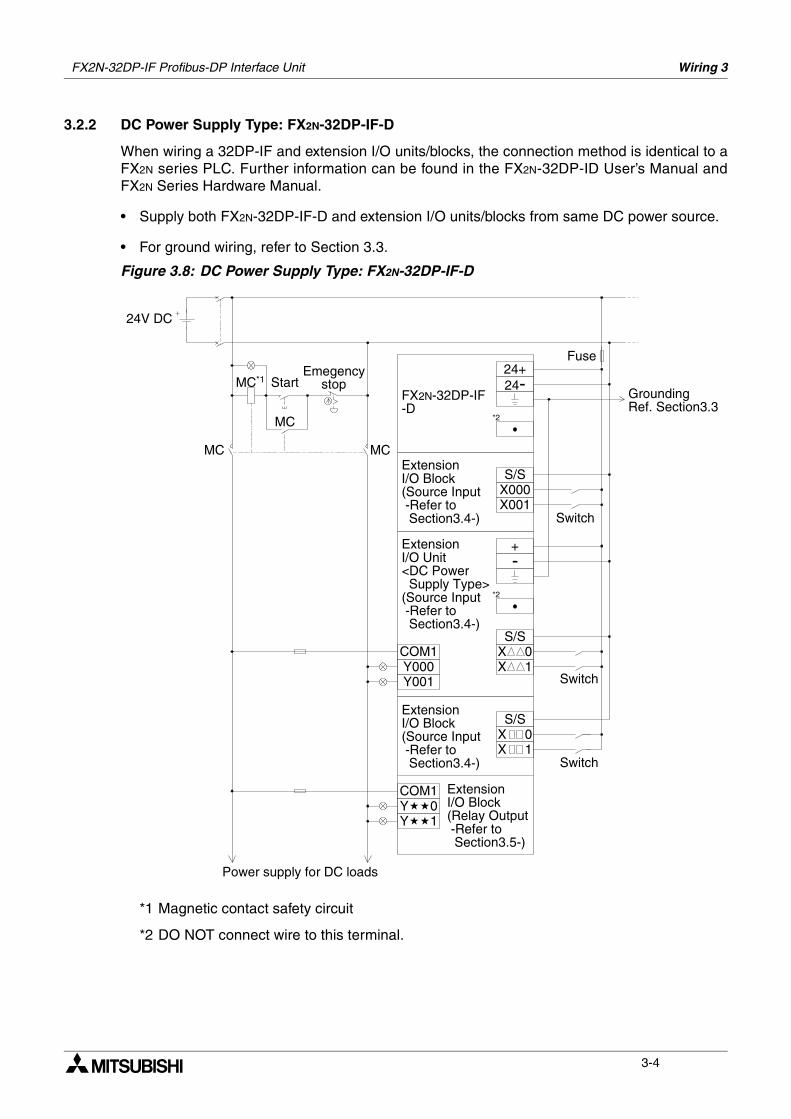
3.2.2 DC Power Supply Type: FX2N-32DP-IF-D
When wiring a 32DP-IF and extension I/O units/blocks, the connection method is identical to aFX2N series PLC. Further information can be found in the FX2N-32DP-ID User’s Manual andFX2N Series Hardware Manual.
• Supply both FX2N-32DP-IF-D and extension I/O units/blocks from same DC power source.
• For ground wiring, refer to Section 3.3.
Figure 3.8: DC Power Supply Type: FX2N-32DP-IF-D
*1 Magnetic contact safety circuit
*2 DO NOT connect wire to this terminal.
24V DC
MC*1 Start
MC
Emegencystop
MC MC
24+24-
S/SX000X001
+-
S/SCOM1Y000Y001
S/S
COM1Y0Y1
ExtensionI/O Block(Relay Output -Refer to Section3.5-)
ExtensionI/O Block(Source Input -Refer to Section3.4-)
ExtensionI/O Unit<DC Power Supply Type>(Source Input -Refer to Section3.4-)
ExtensionI/O Block(Source Input -Refer to Section3.4-)
FX2N-32DP-IF-D
Power supply for DC loads
Switch
Switch
Fuse
GroundingRef. Section3.3
*2
*2
Switch
X 0X 1
X 1X 0
FX2N-32DP-IF Profibus-DP Interface Unit Wiring 3
3-5
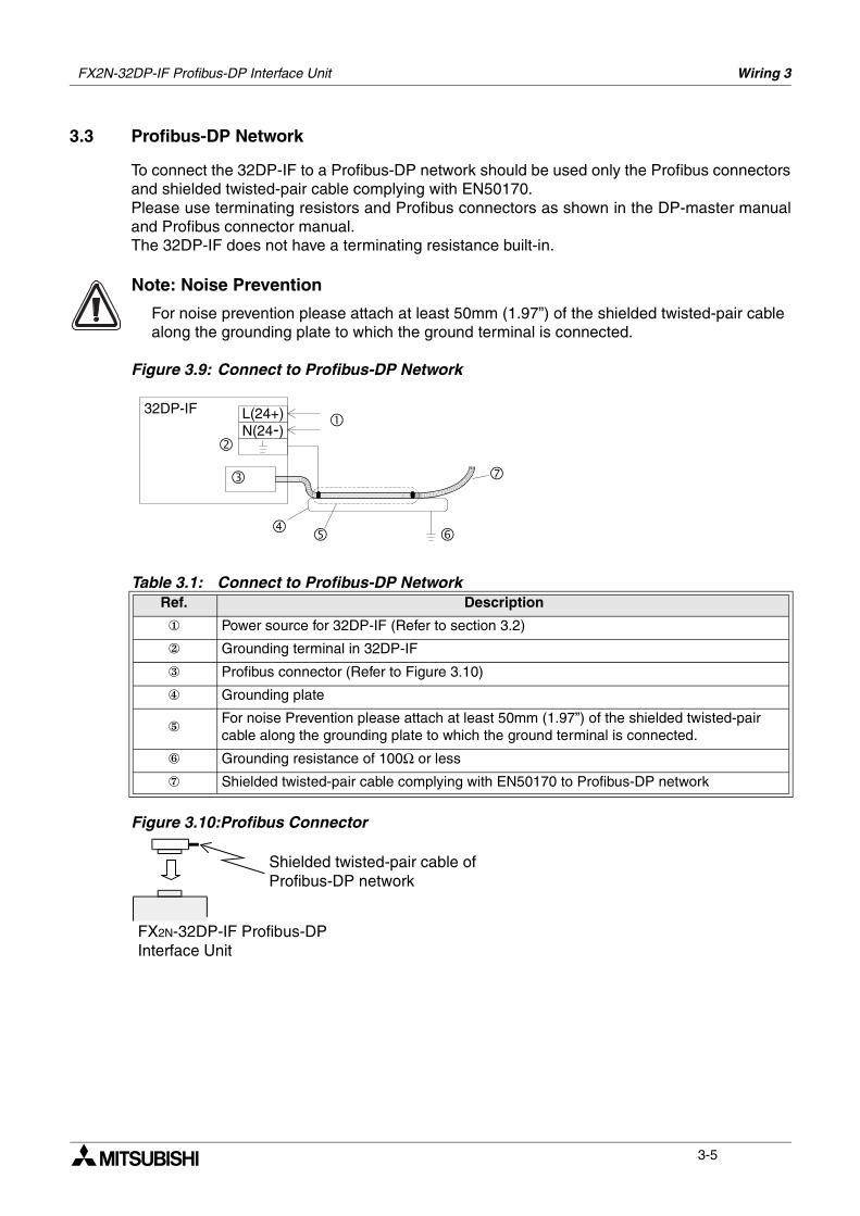
3.3 Profibus-DP Network
To connect the 32DP-IF to a Profibus-DP network should be used only the Profibus connectorsand shielded twisted-pair cable complying with EN50170.Please use terminating resistors and Profibus connectors as shown in the DP-master manualand Profibus connector manual.The 32DP-IF does not have a terminating resistance built-in.
Note: Noise Prevention
For noise prevention please attach at least 50mm (1.97”) of the shielded twisted-pair cable along the grounding plate to which the ground terminal is connected.
Figure 3.9: Connect to Profibus-DP Network
Figure 3.10:Profibus Connector
Table 3.1: Connect to Profibus-DP NetworkRef. Description
Power source for 32DP-IF (Refer to section 3.2)
Grounding terminal in 32DP-IF
Profibus connector (Refer to Figure 3.10)
Grounding plate
For noise Prevention please attach at least 50mm (1.97”) of the shielded twisted-pair cable along the grounding plate to which the ground terminal is connected.
Grounding resistance of 100Ω or less
Shielded twisted-pair cable complying with EN50170 to Profibus-DP network
L(24+)32DP-IF
N(24-)
Shielded twisted-pair cable ofProfibus-DP network
FX2N-32DP-IF Profibus-DPInterface Unit
FX2N-32DP-IF Profibus-DP Interface Unit Wiring 3
3-6
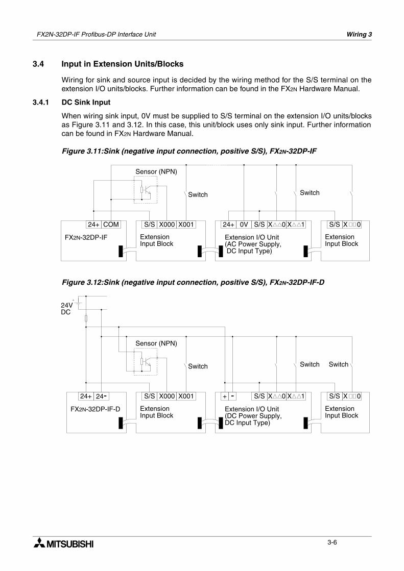
3.4 Input in Extension Units/Blocks
Wiring for sink and source input is decided by the wiring method for the S/S terminal on theextension I/O units/blocks. Further information can be found in the FX2N Hardware Manual.
3.4.1 DC Sink Input
When wiring sink input, 0V must be supplied to S/S terminal on the extension I/O units/blocksas Figure 3.11 and 3.12. In this case, this unit/block uses only sink input. Further informationcan be found in FX2N Hardware Manual.
Figure 3.11:Sink (negative input connection, positive S/S), FX2N-32DP-IF
Figure 3.12:Sink (negative input connection, positive S/S), FX2N-32DP-IF-D
COM24+
FX2N-32DP-IF
S/S X000 X001 24+ 0V X 0S/S X 0S/S
ExtensionInput Block
Sensor (NPN)
Switch Switch
Extension I/O Unit(AC Power Supply, DC Input Type)
ExtensionInput Block
X 1
24+
FX2N-32DP-IF-D
S/S X000 X001 + - X 0S/S X 1 S/S
ExtensionInput Block
Sensor (NPN)
Switch Switch
Extension I/O Unit(DC Power Supply,DC Input Type)
ExtensionInput Block
24-
24VDC
X 0
Switch
FX2N-32DP-IF Profibus-DP Interface Unit Wiring 3
3-7
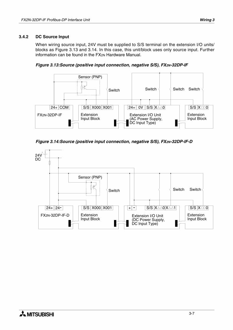
3.4.2 DC Source Input
When wiring source input, 24V must be supplied to S/S terminal on the extension I/O units/blocks as Figure 3.13 and 3.14. In this case, this unit/block uses only source input. Furtherinformation can be found in the FX2N Hardware Manual.
Figure 3.13:Source (positive input connection, negative S/S), FX2N-32DP-IF
Figure 3.14:Source (positive input connection, negative S/S), FX2N-32DP-IF-D
COM24+
FX2N-32DP-IF
S/S X000 X001 24+ 0V X 0S/S X 0S/S
ExtensionInput Block
Sensor (PNP)
Switch Switch
Extension I/O Unit(AC Power Supply,DC Input Type)
ExtensionInput Block
SwitchSwitch
24+
FX2N-32DP-IF-D
S/S X000 X001 + - X 0S/S X 1 S/S
ExtensionInput Block
Sensor (PNP)
Switch Switch
ExtensionInput Block
24-
24VDC
X 0
Switch
Extension I/O Unit(DC Power Supply,DC Input Type)
FX2N-32DP-IF Profibus-DP Interface Unit Wiring 3
3-8
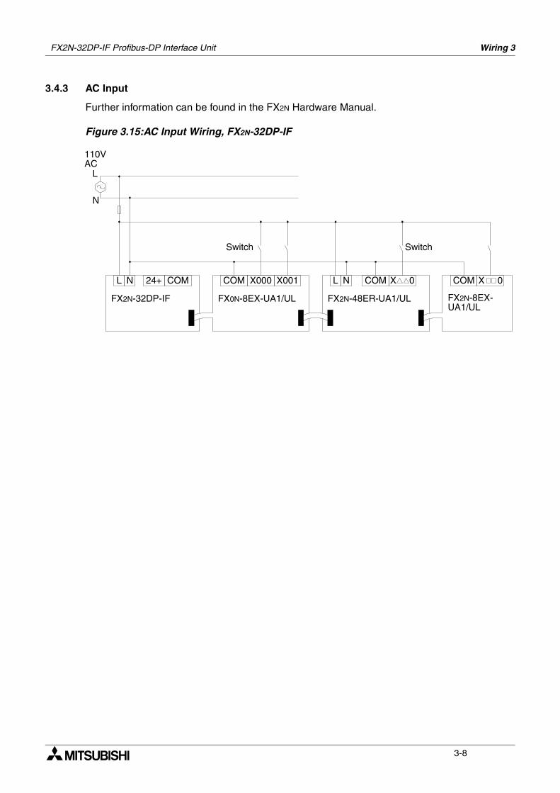
3.4.3 AC Input
Further information can be found in the FX2N Hardware Manual.
Figure 3.15:AC Input Wiring, FX2N-32DP-IF
L
FX2N-32DP-IF
COM X000 X001 L COM X 0 COM
Switch
N
X 0
Switch
N COM24+
FX0N-8EX-UA1/UL FX2N-48ER-UA1/UL
N
110VAC
L
FX2N-8EX-UA1/UL
FX2N-32DP-IF Profibus-DP Interface Unit Wiring 3
3-9
3.5 Output in Extension Units/Blocks
Further information can be found in the FX2N Hardware Manual.
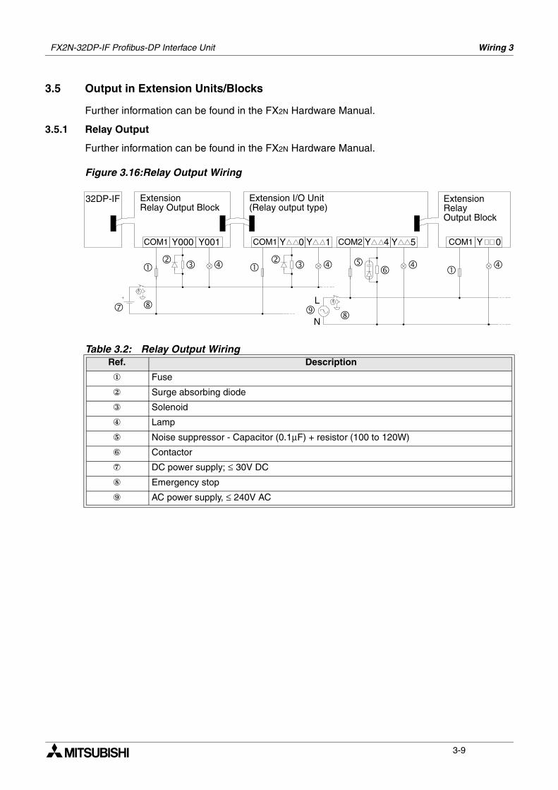
3.5.1 Relay Output
Further information can be found in the FX2N Hardware Manual.
Figure 3.16:Relay Output Wiring
Table 3.2: Relay Output WiringRef. Description
Fuse
Surge absorbing diode
Solenoid
Lamp
Noise suppressor - Capacitor (0.1µF) + resistor (100 to 120W)
Contactor
DC power supply; ≤ 30V DC
Emergency stop
AC power supply, ≤ 240V AC
ExtensionRelay Output Block
COM1 Y000 Y001
Extension I/O Unit(Relay output type)
32DP-IF
Y 0 Y 1 COM2 Y 4 Y 5 Y 0
ExtensionRelayOutput Block
COM1 COM1
L
N
FX2N-32DP-IF Profibus-DP Interface Unit Wiring 3
3-10
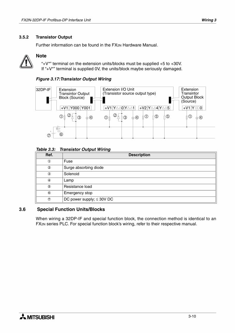
3.5.2 Transistor Output
Further information can be found in the FX2N Hardware Manual.
Note
“+V*” terminal on the extension units/blocks must be supplied +5 to +30V.If “+V*” terminal is supplied 0V, the units/block maybe seriously damaged.
Figure 3.17:Transistor Output Wiring
3.6 Special Function Units/Blocks
When wiring a 32DP-IF and special function block, the connection method is identical to anFX2N series PLC. For special function block’s wiring, refer to their respective manual.
Table 3.3: Transistor Output WiringRef. Description
Fuse
Surge absorbing diode
Solenoid
Lamp
Resistance load
Emergency stop
DC power supply; ≤ 30V DC
ExtensionTransintor OutputBlock (Source)
+V1 Y000 Y001
Extension I/O Unit(Transistor source output type)
32DP-IF
+V1 Y 0 Y 1 +V2 Y 4 Y 5 +V1 Y 0
ExtensionTransintorOutput Block(Source)
Specifications 4
4-1
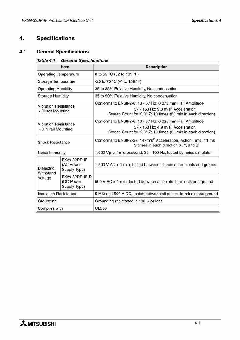
4. Specifications
4.1 General Specifications
Table 4.1: General SpecificationsItem Description
Operating Temperature 0 to 55 °C (32 to 131 °F)
Storage Temperature -20 to 70 °C (-4 to 158 °F)
Operating Humidity 35 to 85% Relative Humidity, No condensation
Storage Humidity 35 to 90% Relative Humidity, No condensation
Vibration Resistance - Direct Mounting
Conforms to EN68-2-6; 10 - 57 Hz: 0.075 mm Half Amplitude
57 - 150 Hz: 9.8 m/s2 Acceleration Sweep Count for X, Y, Z: 10 times (80 min in each direction)
Vibration Resistance - DIN rail Mounting
Conforms to EN68-2-6; 10 - 57 Hz: 0.035 mm Half Amplitude
57 - 150 Hz: 4.9 m/s2 Acceleration Sweep Count for X, Y, Z: 10 times (80 min in each direction)
Shock Resistance Conforms to EN68-2-27: 147m/s2 Acceleration, Action Time: 11 ms 3 times in each direction X, Y, and Z
Noise Immunity 1,000 Vp-p, 1microsecond, 30 - 100 Hz, tested by noise simulator
Dielectric Withstand Voltage
FX2N-32DP-IF(AC Power Supply Type)
1,500 V AC > 1 min, tested between all points, terminals and ground
FX2N-32DP-IF-D(DC Power Supply Type)
500 V AC > 1 min, tested between all points, terminals and ground
Insulation Resistance 5 MΩ > at 500 V DC, tested between all points, terminals and ground
Grounding Grounding resistance is 100 Ω or less
Complies with UL508
FX2N-32DP-IF Profibus-DP Interface Unit
FX2N-32DP-IF Profibus-DP Interface Unit Specifications 4
4-2
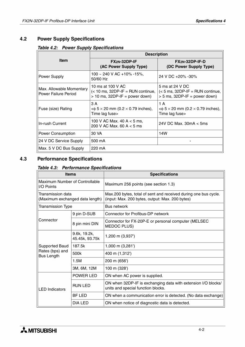
4.2 Power Supply Specifications
4.3 Performance Specifications
Table 4.2: Power Supply Specifications
Item
Description
FX2N-32DP-IF(AC Power Supply Type)
FX2N-32DP-IF-D(DC Power Supply Type)
Power Supply100 ~ 240 V AC +10% -15%, 50/60 Hz
24 V DC +20% -30%
Max. Allowable Momentary Power Failure Period
10 ms at 100 V AC(< 10 ms, 32DP-IF = RUN continue, > 10 ms, 32DP-IF = power down)
5 ms at 24 V DC(< 5 ms, 32DP-IF = RUN continue, > 5 ms, 32DP-IF = power down)
Fuse (size) Rating3 A <φ 5 × 20 mm (0.2 × 0.79 inches), Time lag fuse>
1 A <φ 5 × 20 mm (0.2 × 0.79 inches), Time lag fuse>
In-rush Current100 V AC Max. 40 A < 5 ms, 200 V AC Max. 60 A < 5 ms
24V DC Max. 30mA < 5ms
Power Consumption 30 VA 14W
24 V DC Service Supply 500 mA -
Max. 5 V DC Bus Supply 220 mA
Table 4.3: Performance SpecificationsItems Specifications
Maximum Number of Controllable I/O Points
Maximum 256 points (see section 1.3)
Transmission data (Maximum exchanged data length)
Max.200 bytes, total of sent and received during one bus cycle. (input: Max. 200 bytes, output: Max. 200 bytes)
Transmission Type Bus network
Connector
9 pin D-SUB Connector for Profibus-DP network
8 pin mini DINConnector for FX-20P-E or personal computer (MELSEC MEDOC PLUS)
Supported Baud Rates (bps) and Bus Length
9.6k, 19.2k, 45.45k, 93.75k
1,200 m (3,937')
187.5k 1,000 m (3,281')
500k 400 m (1,312')
1.5M 200 m (656')
3M, 6M, 12M 100 m (328')
LED Indicators
POWER LED ON when AC power is supplied.
RUN LEDON when 32DP-IF is exchanging data with extension I/O blocks/units and special function blocks.
BF LED ON when a communication error is detected. (No data exchange)
DIA LED ON when notice of diagnostic data is detected.
Advanced Devices 5
5-1
5. Advanced Devices
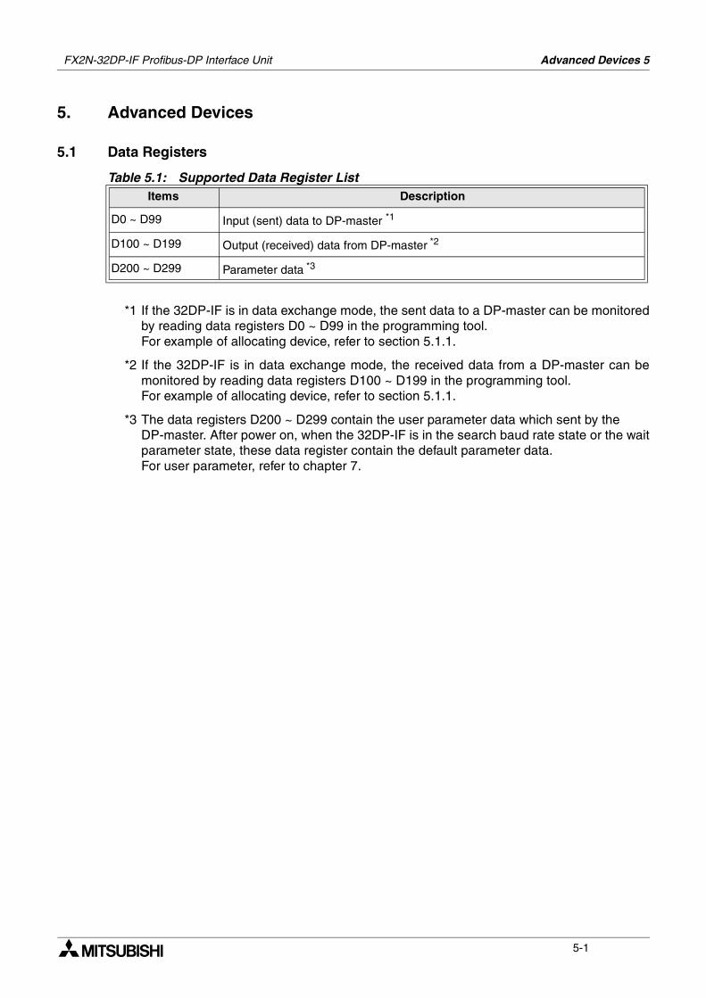
5.1 Data Registers
*1 If the 32DP-IF is in data exchange mode, the sent data to a DP-master can be monitoredby reading data registers D0 ~ D99 in the programming tool. For example of allocating device, refer to section 5.1.1.
*2 If the 32DP-IF is in data exchange mode, the received data from a DP-master can bemonitored by reading data registers D100 ~ D199 in the programming tool. For example of allocating device, refer to section 5.1.1.
*3 The data registers D200 ~ D299 contain the user parameter data which sent by the DP-master. After power on, when the 32DP-IF is in the search baud rate state or the waitparameter state, these data register contain the default parameter data.For user parameter, refer to chapter 7.
Table 5.1: Supported Data Register ListItems Description
D0 ~ D99 Input (sent) data to DP-master *1
D100 ~ D199 Output (received) data from DP-master *2
D200 ~ D299 Parameter data *3
FX2N-32DP-IF Profibus-DP Interface Unit
FX2N-32DP-IF Profibus-DP Interface Unit Advanced Devices 5
5-2
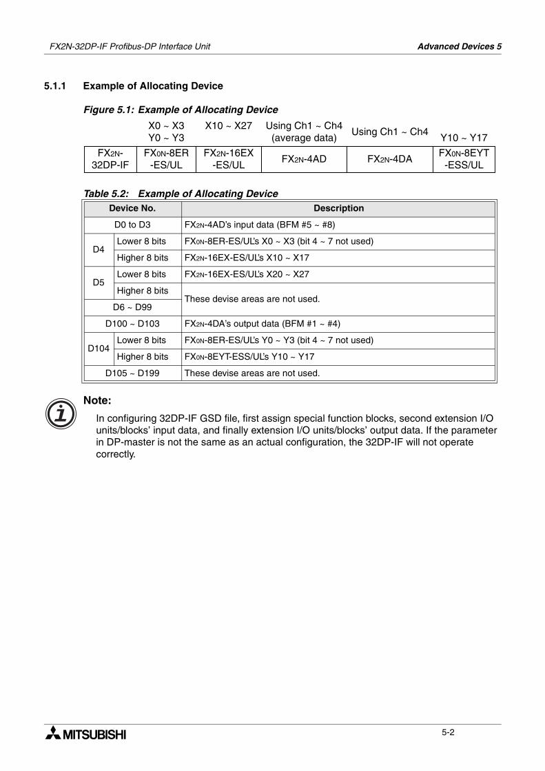
5.1.1 Example of Allocating Device
Figure 5.1: Example of Allocating Device
Note:
In configuring 32DP-IF GSD file, first assign special function blocks, second extension I/O units/blocks’ input data, and finally extension I/O units/blocks’ output data. If the parameter in DP-master is not the same as an actual configuration, the 32DP-IF will not operate correctly.
Table 5.2: Example of Allocating DeviceDevice No. Description
D0 to D3 FX2N-4AD’s input data (BFM #5 ~ #8)
D4Lower 8 bits FX0N-8ER-ES/UL’s X0 ~ X3 (bit 4 ~ 7 not used)
Higher 8 bits FX2N-16EX-ES/UL’s X10 ~ X17
D5Lower 8 bits FX2N-16EX-ES/UL’s X20 ~ X27
Higher 8 bitsThese devise areas are not used.
D6 ~ D99
D100 ~ D103 FX2N-4DA’s output data (BFM #1 ~ #4)
D104Lower 8 bits FX0N-8ER-ES/UL’s Y0 ~ Y3 (bit 4 ~ 7 not used)
Higher 8 bits FX0N-8EYT-ESS/UL’s Y10 ~ Y17
D105 ~ D199 These devise areas are not used.
FX2N-32DP-IF
FX2N-4ADFX0N-8ER
-ES/ULFX2N-4DA
FX2N-16EX-ES/UL
FX0N-8EYT-ESS/UL
X0 ~ X3Y0 ~ Y3
X10 ~ X27Y10 ~ Y17
Using Ch1 ~ Ch4(average data)
Using Ch1 ~ Ch4
FX2N-32DP-IF Profibus-DP Interface Unit Advanced Devices 5
5-3
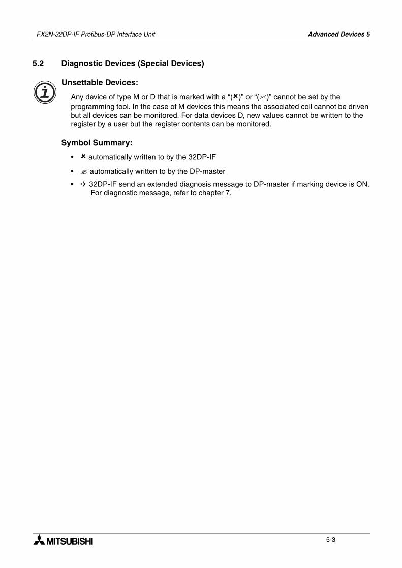
5.2 Diagnostic Devices (Special Devices)
Unsettable Devices:
Any device of type M or D that is marked with a “()” or “()” cannot be set by the programming tool. In the case of M devices this means the associated coil cannot be driven but all devices can be monitored. For data devices D, new values cannot be written to the register by a user but the register contents can be monitored.
Symbol Summary:
• automatically written to by the 32DP-IF
• automatically written to by the DP-master
• 32DP-IF send an extended diagnosis message to DP-master if marking device is ON. For diagnostic message, refer to chapter 7.
FX2N-32DP-IF Profibus-DP Interface Unit Advanced Devices 5
5-4
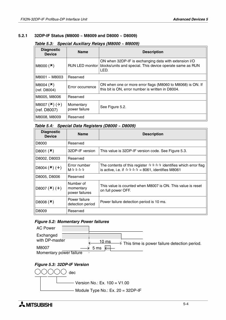
5.2.1 32DP-IF Status (M8000 ~ M8009 and D8000 ~ D8009)
Figure 5.2: Momentary Power failures
Figure 5.3: 32DP-IF Version
Table 5.3: Special Auxiliary Relays (M8000 ~ M8009)Diagnostic
DeviceName Description
M8000 () RUN LED monitorON when 32DP-IF is exchanging data with extension I/O blocks/units and special. This device operate same as RUN LED.
M8001 ~ M8003 Reserved
M8004 ()(ref. D8004)
Error occurrenceON when one or more error flags (M8060 to M8068) is ON. If this bit is ON, error number is written in D8004.
M8005, M8006 Reserved
M8007 () ()(ref. D8007)
Momentary power failure
See Figure 5.2.
M8008, M8009 Reserved
Table 5.4: Special Data Registers (D8000 ~ D8009)Diagnostic
DeviceName Description
D8000 Reserved
D8001 () 32DP-IF version This value is 32DP-IF version code. See Figure 5.3.
D8002, D8003 Reserved
D8004 () ()Error number M
The contents of this register identifies which error flag is active, i.e. if = 8061, identifies M8061
D8005, D8006 Reserved
D8007 () ()Number of momentary power failures
This value is counted when M8007 is ON. This value is reset on full power OFF.
D8008 ()Power failure detection period
Power failure detection period is 10 ms.
D8009 Reserved
AC Power
Exchangedwith DP-master
M8007Momentary power failure
10 ms
5 msThis time is power failure detection period.
Version No.: Ex. 100 = V1.00
Module Type No.: Ex. 20 = 32DP-IF
dec
FX2N-32DP-IF Profibus-DP Interface Unit Advanced Devices 5
5-5
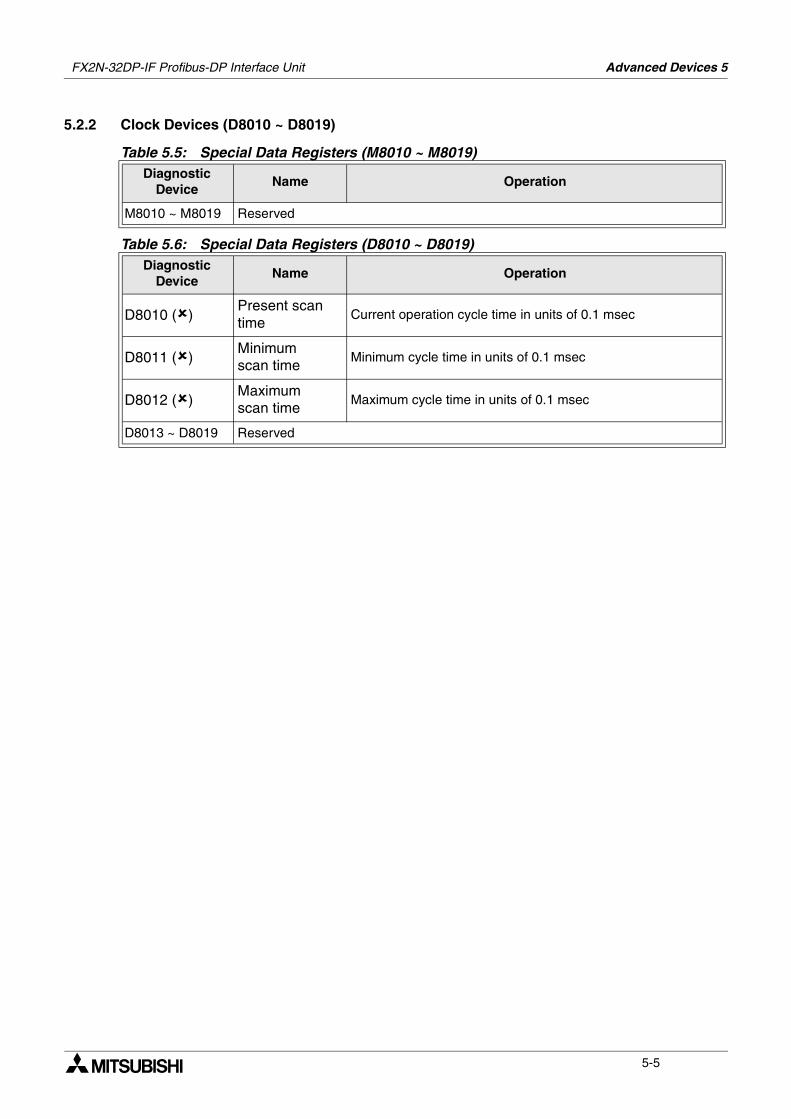
5.2.2 Clock Devices (D8010 ~ D8019)
Table 5.5: Special Data Registers (M8010 ~ M8019)Diagnostic
DeviceName Operation
M8010 ~ M8019 Reserved
Table 5.6: Special Data Registers (D8010 ~ D8019)Diagnostic
DeviceName Operation
D8010 ()Present scantime
Current operation cycle time in units of 0.1 msec
D8011 ()Minimumscan time
Minimum cycle time in units of 0.1 msec
D8012 ()Maximumscan time
Maximum cycle time in units of 0.1 msec
D8013 ~ D8019 Reserved
FX2N-32DP-IF Profibus-DP Interface Unit Advanced Devices 5
5-6
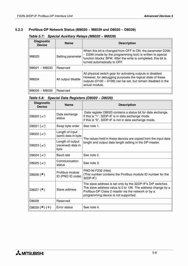
5.2.3 Profibus-DP Network Status (M8020 ~ M8039 and D8020 ~ D8039)
Table 5.7: Special Auxiliary Relays (M8020 ~ M8039)Diagnostic
DeviceName Description
M8020 Setting parameter
When this bit is changed from OFF to ON, the parameter D200 ~ D299 (made by the programming tool) is written to special function blocks’ BFM. After the write is completed, this bit is turned automatically to OFF.
M8021 ~ M8033 Reserved
M8034 All output disable
All physical switch gear for activating outputs is disabled. However, for debugging purposes the logical state of these outputs (D100 ~ D199) can be set, but remain disabled in the actual module.
M8035 ~ M8039 Reserved
Table 5.8: Special Data Registers (D8020 ~ D8039)Diagnostic
DeviceName Description
D8020 () Data exchange status
Data register D8020 contains a status bit for data exchange. If this is “1”, 32DP-IF is in data exchange mode.If this is “0”, 32DP-IF is not in data exchange mode.
D8021 () Swap byte order See note 1.
D8022 () Length of input (sent) data in byte
The values held in these devices are copied from the input data length and output data length setting in the DP-master.
D8023 ()Length of output (received) data in byte
D8024 () Baud rate See note 2.
D8025 () Communication status
See note 3.
D8026 ()Profibus module ID (PNO ID code)
PNO-Nr.F232 (Hex)(This number contains the Profibus module ID number for the 32DP-IF.)
D8027 () Slave address
The slave address is set only by the 32DP-IF’s DIP switches. The slave address value is 0 to 126. The address change by a Profibus-DP Class 2 master via the network or by a programming device is not supported.
D8028 Reserved
D8029 () () Error status See note 4.
FX2N-32DP-IF Profibus-DP Interface Unit Advanced Devices 5
5-7
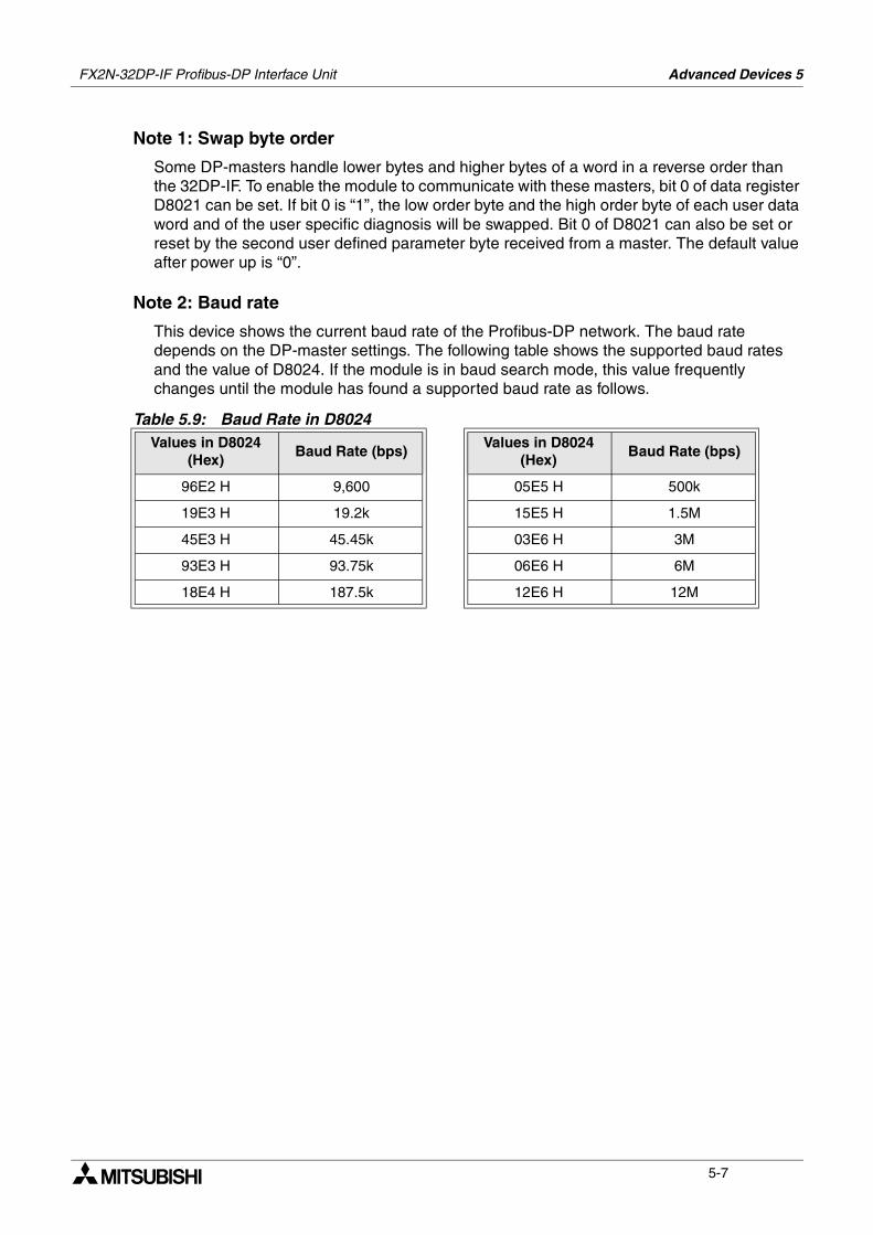
Note 1: Swap byte order
Some DP-masters handle lower bytes and higher bytes of a word in a reverse order than the 32DP-IF. To enable the module to communicate with these masters, bit 0 of data register D8021 can be set. If bit 0 is “1”, the low order byte and the high order byte of each user data word and of the user specific diagnosis will be swapped. Bit 0 of D8021 can also be set or reset by the second user defined parameter byte received from a master. The default value after power up is “0”.
Note 2: Baud rate
This device shows the current baud rate of the Profibus-DP network. The baud rate depends on the DP-master settings. The following table shows the supported baud rates and the value of D8024. If the module is in baud search mode, this value frequently changes until the module has found a supported baud rate as follows.
Table 5.9: Baud Rate in D8024Values in D8024
(Hex)Baud Rate (bps)
Values in D8024 (Hex)
Baud Rate (bps)
96E2 H 9,600 05E5 H 500k
19E3 H 19.2k 15E5 H 1.5M
45E3 H 45.45k 03E6 H 3M
93E3 H 93.75k 06E6 H 6M
18E4 H 187.5k 12E6 H 12M
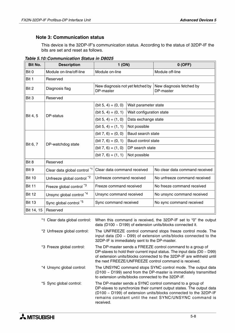
FX2N-32DP-IF Profibus-DP Interface Unit Advanced Devices 5
5-8
Note 3: Communication status
This device is the 32DP-IF’s communication status. According to the status of 32DP-IF the bits are set and reset as follows.
*1 Clear data global control: When this command is received, the 32DP-IF set to “0” the outputdata (D100 ~ D199) of extension units/blocks connected it.
*2 Unfreeze global control: The UNFREEZE control command stops freeze control mode. Theinput data (D0 ~ D99) of extension units/blocks connected to the32DP-IF is immediately sent to the DP-master.
*3 Freeze global control: The DP-master sends a FREEZE control command to a group of DP-slaves to hold their current input status. The input data (D0 ~ D99)of extension units/blocks connected to the 32DP-IF are withheld untilthe next FREEZE/UNFREEZE control command is received.
*4 Unsync global control: The UNSYNC command stops SYNC control mode. The output data(D100 ~ D199) send from the DP-master is immediately transmittedto extension units/blocks connected to the 32DP-IF.
*5 Sync global control: The DP-master sends a SYNC control command to a group of DP-slaves to synchronize their current output states. The output data(D100 ~ D199) of extension units/blocks connected to the 32DP-IFremains constant until the next SYNC/UNSYNC command isreceived.
Table 5.10:Communication Status in D8025Bit No. Description 1 (ON) 0 (OFF)
Bit 0 Module on-line/off-line Module on-line Module off-line
Bit 1 Reserved
Bit 2 Diagnosis flagNew diagnosis not yet fetched by DP-master
New diagnosis fetched by DP-master
Bit 3 Reserved
Bit 4, 5 DP-status
(bit 5, 4) = (0, 0) Wait parameter state
(bit 5, 4) = (0, 1) Wait configuration state
(bit 5, 4) = (1, 0) Data exchange state
(bit 5, 4) = (1, 1) Not possible
Bit 6, 7 DP-watchdog state
(bit 7, 6) = (0, 0) Baud search state
(bit 7, 6) = (0, 1) Baud control state
(bit 7, 6) = (1, 0) DP search state
(bit 7, 6) = (1, 1) Not possible
Bit 8 Reserved
BIt 9 Clear data global control *1 Clear data command received No clear data command received
Bit 10 Unfreeze global control *2 Unfreeze command received No unfreeze command received
Bit 11 Freeze global control *3 Freeze command received No freeze command received
Bit 12 Unsync global control *4 Unsync command received No unsync command received
Bit 13 Sync global control *5 Sync command received No sync command received
Bit 14, 15 Reserved
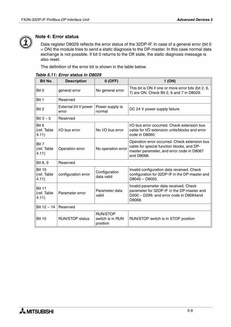
FX2N-32DP-IF Profibus-DP Interface Unit Advanced Devices 5
5-9
Note 4: Error status
Data register D8029 reflects the error status of the 32DP-IF. In case of a general error (bit 0 = ON) the module tries to send a static diagnosis to the DP-master. In this case normal data exchange is not possible. If bit 0 returns to the Off state, the static diagnosis message is also reset.
The definition of the error bit is shown in the table below.
Table 5.11: Error status in D8029Bit No. Description 0 (OFF) 1 (ON)
Bit 0 general error No general errorThis bit is ON if one or more error bits (bit 2, 6, 7) are ON. Check Bit 2, 6 and 7 in D8029.
Bit 1 Reserved
Bit 2External 24 V power error
Power supply is normal
DC 24 V power supply failure
Bit 3 ~ 5 Reserved
Bit 6(ref. Table 4.11)
I/O bus error No I/O bus errorI/O bus error occurred. Check extension bus cable for I/O extension units/blocks and error code in D8060.
Bit 7(ref. Table 4.11)
Operation error No operation error
Operation error occurred. Check extension bus cable for special function blocks, and DP-master parameter, and error code in D8067 and D8068.
Bit 8, 9 Reserved
Bit 10(ref. Table 4.11)
configuration errorConfiguration data valid
Invalid configuration data received. Check configuration for 32DP-IF in the DP-master and D8040 ~ D8055.
Bit 11(ref. Table 4.11)
Parameter errorParameter data valid
Invalid parameter data received. Check parameter for 32DP-IF in the DP-master and D200 ~ D299, and error code in D8064and D8068.
Bit 12 ~ 14 Reserved
Bit 15 RUN/STOP statusRUN/STOP switch is in RUN position
RUN/STOP switch is in STOP position
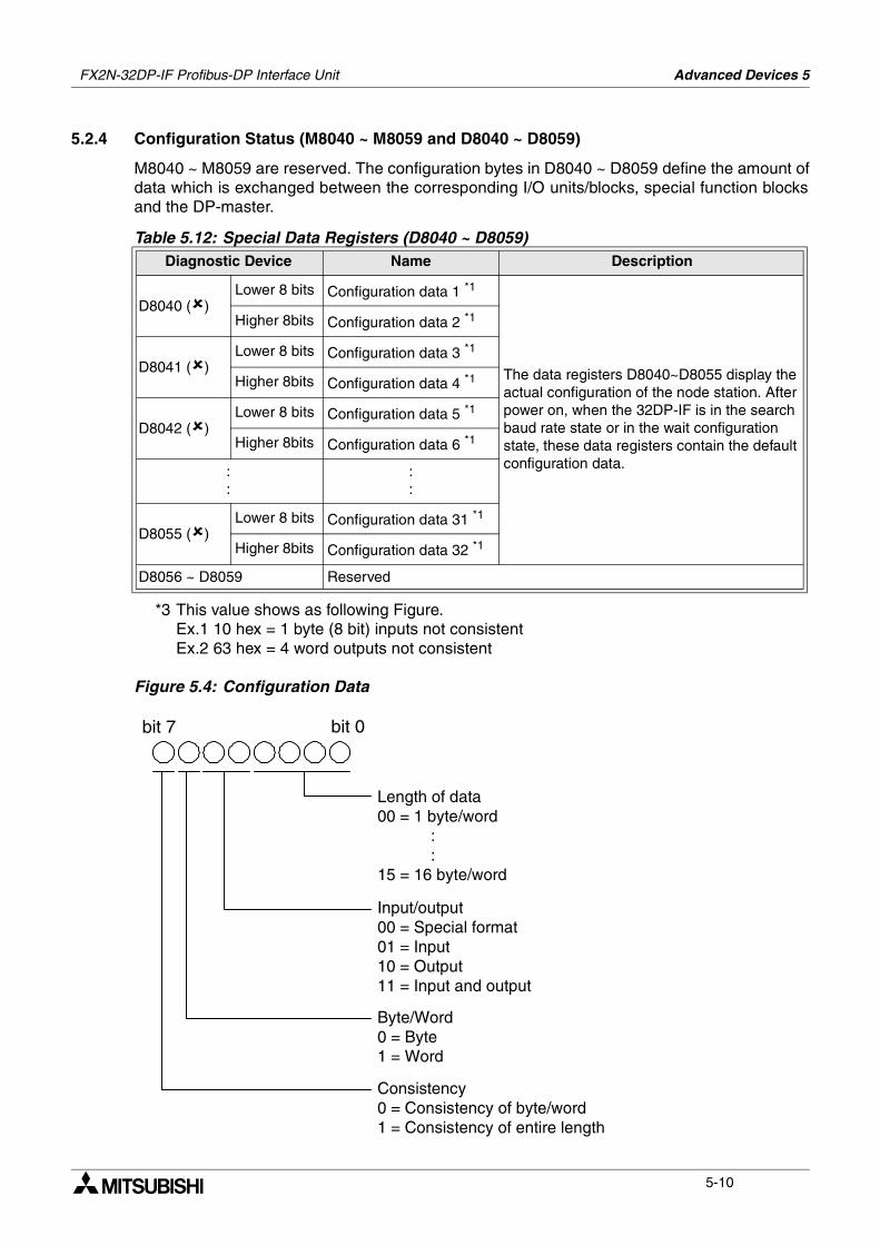
FX2N-32DP-IF Profibus-DP Interface Unit Advanced Devices 5
5-10
5.2.4 Configuration Status (M8040 ~ M8059 and D8040 ~ D8059)
M8040 ~ M8059 are reserved. The configuration bytes in D8040 ~ D8059 define the amount ofdata which is exchanged between the corresponding I/O units/blocks, special function blocksand the DP-master.
*3 This value shows as following Figure. Ex.1 10 hex = 1 byte (8 bit) inputs not consistentEx.2 63 hex = 4 word outputs not consistent
Figure 5.4: Configuration Data
Table 5.12: Special Data Registers (D8040 ~ D8059)Diagnostic Device Name Description
D8040 ()Lower 8 bits Configuration data 1 *1
The data registers D8040~D8055 display the actual configuration of the node station. After power on, when the 32DP-IF is in the search baud rate state or in the wait configuration state, these data registers contain the default configuration data.
Higher 8bits Configuration data 2 *1
D8041 ()Lower 8 bits Configuration data 3 *1
Higher 8bits Configuration data 4 *1
D8042 ()Lower 8 bits Configuration data 5 *1
Higher 8bits Configuration data 6 *1
::
::
D8055 ()Lower 8 bits Configuration data 31 *1
Higher 8bits Configuration data 32 *1
D8056 ~ D8059 Reserved
Length of data00 = 1 byte/word : :15 = 16 byte/word
Input/output00 = Special format01 = Input10 = Output11 = Input and output
Byte/Word0 = Byte1 = Word
Consistency0 = Consistency of byte/word1 = Consistency of entire length
bit 0bit 7
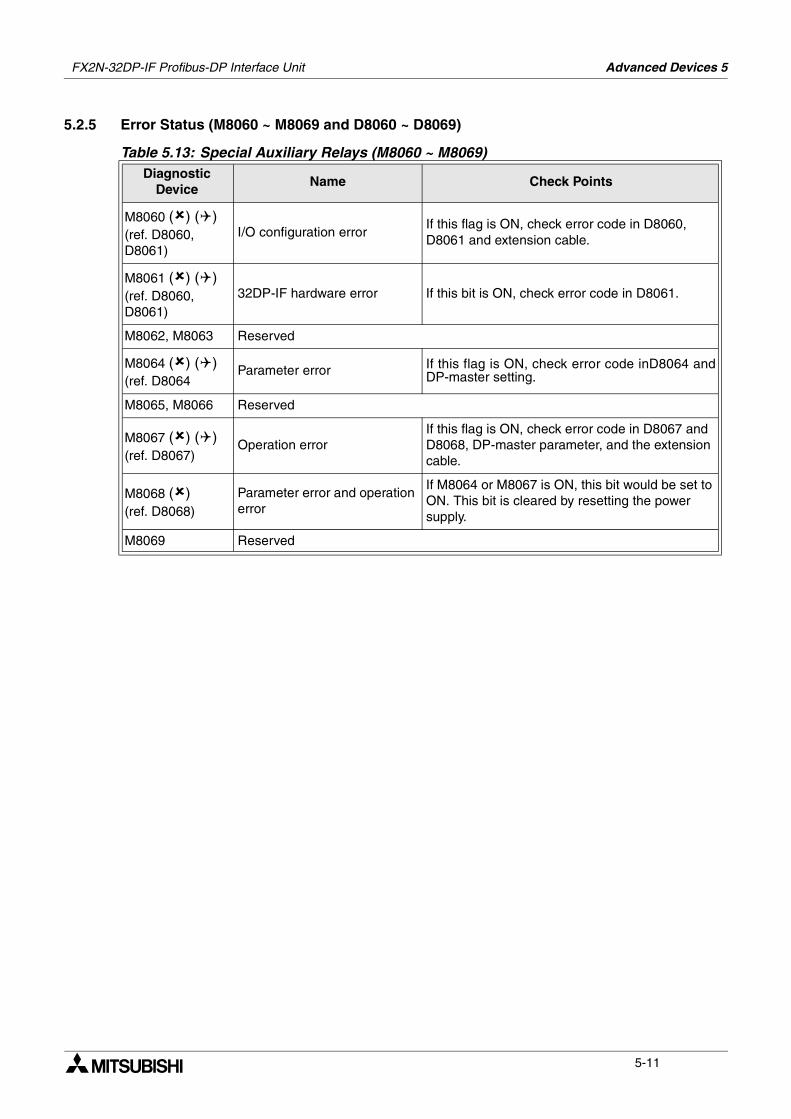
FX2N-32DP-IF Profibus-DP Interface Unit Advanced Devices 5
5-11
5.2.5 Error Status (M8060 ~ M8069 and D8060 ~ D8069)
Table 5.13: Special Auxiliary Relays (M8060 ~ M8069)Diagnostic
DeviceName Check Points
M8060 () ()(ref. D8060, D8061)
I/O configuration errorIf this flag is ON, check error code in D8060, D8061 and extension cable.
M8061 () ()(ref. D8060, D8061)
32DP-IF hardware error If this bit is ON, check error code in D8061.
M8062, M8063 Reserved
M8064 () ()(ref. D8064
Parameter error If this flag is ON, check error code inD8064 andDP-master setting.
M8065, M8066 Reserved
M8067 () ()(ref. D8067)
Operation errorIf this flag is ON, check error code in D8067 and D8068, DP-master parameter, and the extension cable.
M8068 ()(ref. D8068)
Parameter error and operation error
If M8064 or M8067 is ON, this bit would be set to ON. This bit is cleared by resetting the power supply.
M8069 Reserved
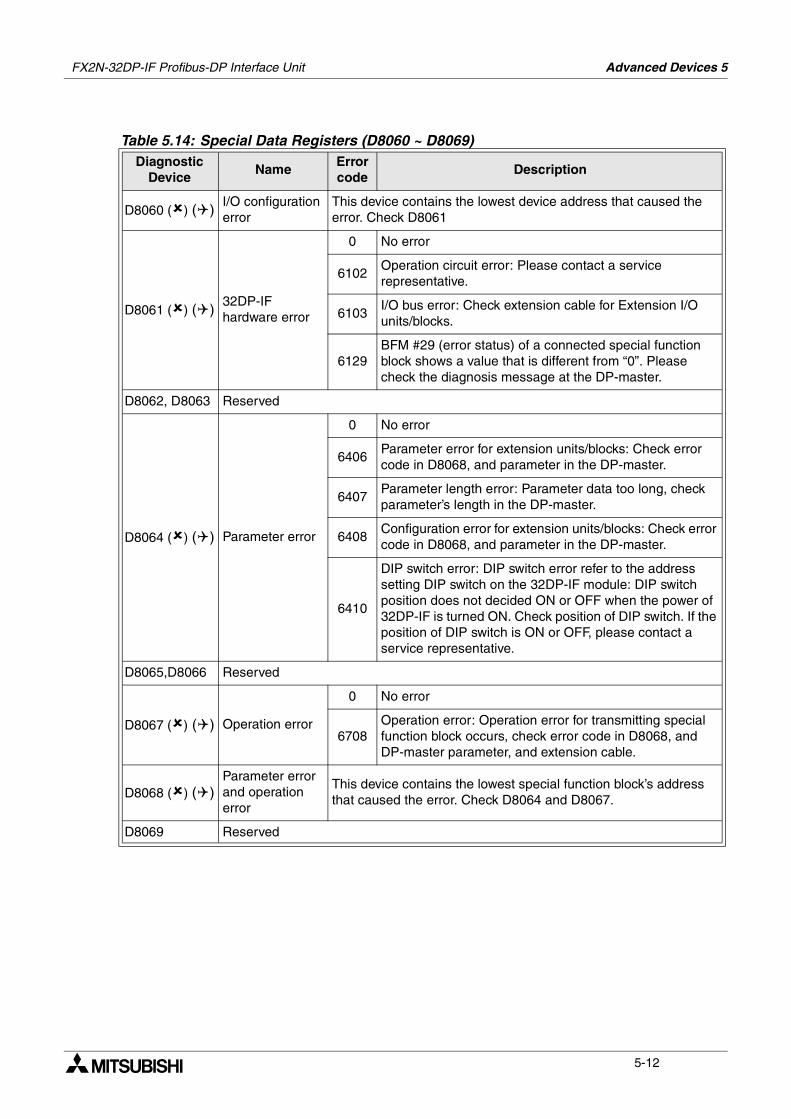
FX2N-32DP-IF Profibus-DP Interface Unit Advanced Devices 5
5-12
Table 5.14: Special Data Registers (D8060 ~ D8069)Diagnostic
DeviceName
Error code
Description
D8060 () ()I/O configuration error
This device contains the lowest device address that caused the error. Check D8061
D8061 () ()32DP-IF hardware error
0 No error
6102Operation circuit error: Please contact a service representative.
6103I/O bus error: Check extension cable for Extension I/O units/blocks.
6129BFM #29 (error status) of a connected special function block shows a value that is different from “0”. Please check the diagnosis message at the DP-master.
D8062, D8063 Reserved
D8064 () () Parameter error
0 No error
6406Parameter error for extension units/blocks: Check error code in D8068, and parameter in the DP-master.
6407Parameter length error: Parameter data too long, check parameter’s length in the DP-master.
6408Configuration error for extension units/blocks: Check error code in D8068, and parameter in the DP-master.
6410
DIP switch error: DIP switch error refer to the address setting DIP switch on the 32DP-IF module: DIP switch position does not decided ON or OFF when the power of 32DP-IF is turned ON. Check position of DIP switch. If the position of DIP switch is ON or OFF, please contact a service representative.
D8065,D8066 Reserved
D8067 () () Operation error
0 No error
6708Operation error: Operation error for transmitting special function block occurs, check error code in D8068, and DP-master parameter, and extension cable.
D8068 () ()Parameter error and operation error
This device contains the lowest special function block’s address that caused the error. Check D8064 and D8067.
D8069 Reserved
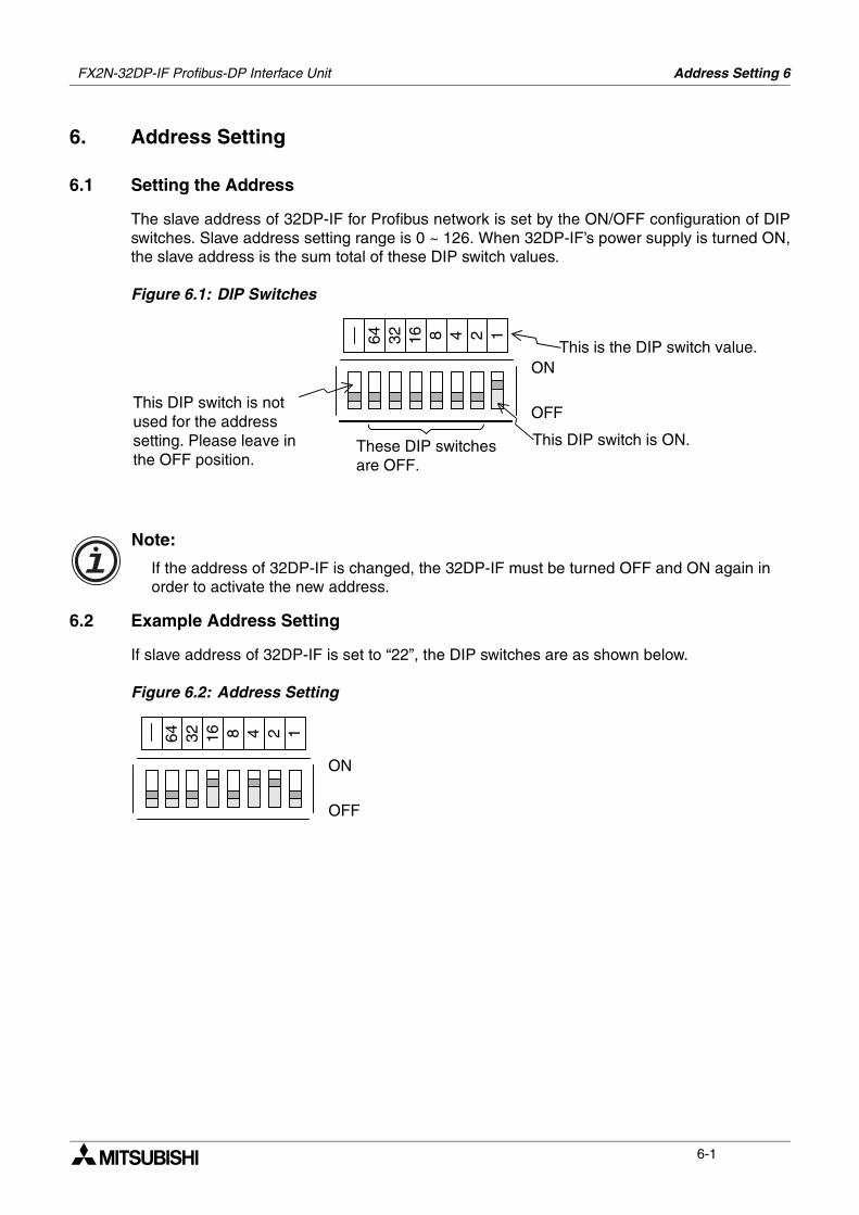
Address Setting 6
6-1
6. Address Setting
6.1 Setting the Address
The slave address of 32DP-IF for Profibus network is set by the ON/OFF configuration of DIPswitches. Slave address setting range is 0 ~ 126. When 32DP-IF’s power supply is turned ON,the slave address is the sum total of these DIP switch values.
Figure 6.1: DIP Switches
Note:
If the address of 32DP-IF is changed, the 32DP-IF must be turned OFF and ON again in order to activate the new address.
6.2 Example Address Setting
If slave address of 32DP-IF is set to “22”, the DIP switches are as shown below.
Figure 6.2: Address Setting
These DIP switchesare OFF.
This DIP switch is notused for the addresssetting. Please leave inthe OFF position.
This DIP switch is ON.
ON
OFF
64 32 16 8 4 2 1
This is the DIP switch value.
ON
OFF
64 32 16 8 4 2 1
FX2N-32DP-IF Profibus-DP Interface Unit

FX2N-32DP-IF Profibus-DP Interface Unit Address Setting 6
6-2
MEMO
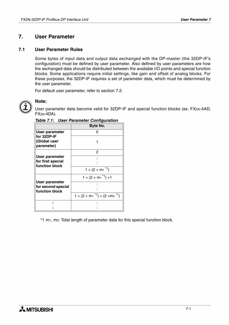
User Parameter 7
7-1
7. User Parameter
7.1 User Parameter Rules
Some bytes of input data and output data exchanged with the DP-master (the 32DP-IF’sconfiguration) must be defined by user parameter. Also defined by user parameters are howthe exchanged data should be distributed between the available I/O points and special functionblocks. Some applications require initial settings, like gain and offset of analog blocks. Forthese purposes, the 32DP-IF requires a set of parameter data, which must be determined bythe user parameter.
For default user parameter, refer to section 7.2.
Note:
User parameter data become valid for 32DP-IF and special function blocks (ex. FX2N-4AD,FX2N-4DA).
*1 m1, m2: Total length of parameter data for this special function block.
Table 7.1: User Parameter ConfigurationByte No.
User parameter for 32DP-IF (Global user parameter)
0
1
User parameter for first special function block
2
::
1 + (2 + m1 *1)
User parameter for second special function block
1 + (2 + m1 *1) +1
::
1 + (2 + m1 *1) + (2 +m2 *1)
::
::
FX2N-32DP-IF Profibus-DP Interface Unit
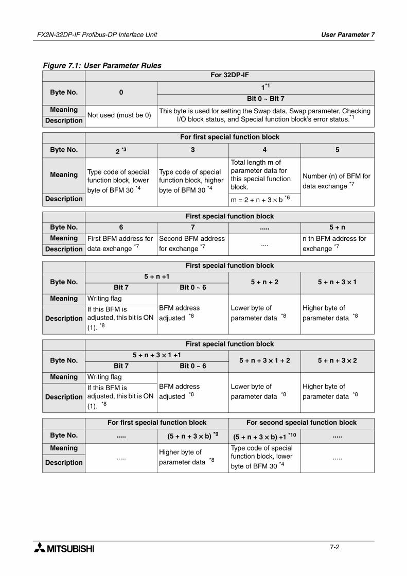
FX2N-32DP-IF Profibus-DP Interface Unit User Parameter 7
7-2
Figure 7.1: User Parameter RulesFor 32DP-IF
Byte No. 01*1
Bit 0 ~ Bit 7
MeaningNot used (must be 0)
This byte is used for setting the Swap data, Swap parameter, Checking I/O block status, and Special function block’s error status.*1Description
For first special function block
Byte No. 2 *3 3 4 5
Meaning Type code of special function block, lower
byte of BFM 30 *4
Type code of special function block, higher
byte of BFM 30 *4
Total length m of parameter data for this special function block.
Number (n) of BFM for
data exchange *7
Description m = 2 + n + 3 × b *6
First special function block
Byte No. 6 7 ..... 5 + n
Meaning First BFM address for
data exchange *7Second BFM address
for exchange *7....
n th BFM address for
exchange *7Description
First special function block
Byte No.5 + n +1
5 + n + 2 5 + n + 3 ×××× 1Bit 7 Bit 0 ~ 6
Meaning Writing flagBFM address
adjusted *8Lower byte of
parameter data *8Higher byte of
parameter data *8DescriptionIf this BFM is adjusted, this bit is ON
(1). *8
First special function block
Byte No.5 + n + 3 ×××× 1 +1
5 + n + 3 ×××× 1 + 2 5 + n + 3 ×××× 2Bit 7 Bit 0 ~ 6
Meaning Writing flagBFM address
adjusted *8Lower byte of
parameter data *8Higher byte of
parameter data *8DescriptionIf this BFM is adjusted, this bit is ON
(1). *8
For first special function block For second special function block
Byte No. ..... (5 + n + 3 ×××× b) *9 (5 + n + 3 ×××× b) +1 *10 .....
Meaning.....
Higher byte of
parameter data *8
Type code of special function block, lower
byte of BFM 30 *4.....
Description

FX2N-32DP-IF Profibus-DP Interface Unit User Parameter 7
7-3
*1 This byte is used for setting the Swap data, Swap parameter, Checking I/O block status,and Special function block’s error status. See the following table.
*2 These bit settings are different depending upon the connected master module.
a) When connecting the A and Q series (MITSUBISHI) master module, these bits set toOFF (Intel format).
b) When connecting other master module, please check these points in the mastermodule’s manual.
*3 This byte number is the first parameter data of first special function block.
Table 7.2: Swap Data, Swap Parameter, Checking I/O Block Status, and Special Function Block’s Status
Bit No. Meaning Description
b0*2 Swap data(Motorola/Intel)
This bit is used for swapping the byte data within the word data of special function block’s BFMs.1) When this bit is OFF (0), byte data is Intel format
within the word data. (Not swapped)2) When this bit is ON (1), byte data is Motorola
format within the word data. (Swapped)
b1 Cyclic status check of I/O units
This bit is used for checking status of I/O block.1) When this bit is OFF (0), the status check of the
I/O units/blocks is not performed.2) When this bit is ON (1), the status check of the I/O
units/blocks is performed in every cycle.
b2 Error check of special function units/blocks
This bit is used for checking the error status (BFM #29) of special function blocks.1) When this bit is OFF (0), error status (BFM #29) in
all connected special function blocks is not checked.
2) When this bit is ON (1), error status (BFM #29) in all connected special function blocks is checked in every cycle.However, the following modules are not checked.• FX2N-10GM• FX2N-20GM• FX2N-2AD• FX2N-2DA• FX0N-3A
b3*2Swap word parameter for BFMs(Motorola/Intel)
This bit is used for swapping byte data within the word parameter.1) When this bit is OFF (0), byte data is Intel format
within the word parameter. (Not swapped)2) When this bit is ON (1), byte data is Motorola
format within the word parameter. (Swapped)
b4 ~ b7 Not used (These bits are always OFF.)
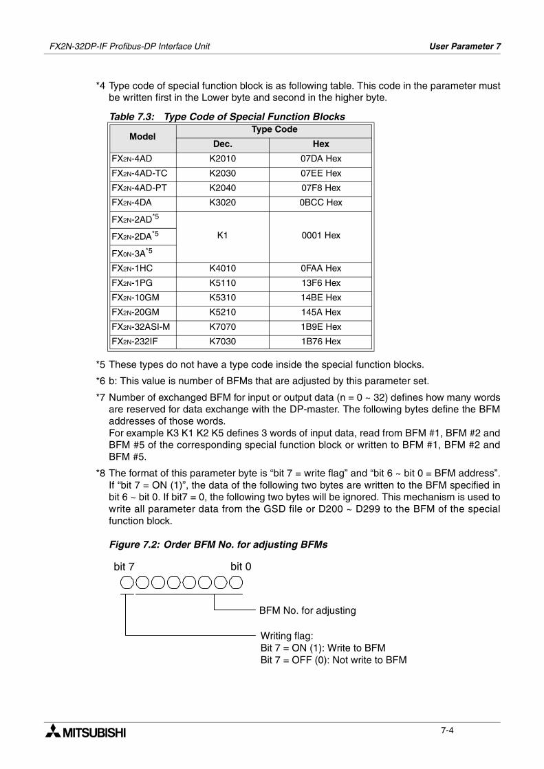
FX2N-32DP-IF Profibus-DP Interface Unit User Parameter 7
7-4
*4 Type code of special function block is as following table. This code in the parameter mustbe written first in the Lower byte and second in the higher byte.
*5 These types do not have a type code inside the special function blocks.
*6 b: This value is number of BFMs that are adjusted by this parameter set.
*7 Number of exchanged BFM for input or output data (n = 0 ~ 32) defines how many wordsare reserved for data exchange with the DP-master. The following bytes define the BFMaddresses of those words. For example K3 K1 K2 K5 defines 3 words of input data, read from BFM #1, BFM #2 andBFM #5 of the corresponding special function block or written to BFM #1, BFM #2 andBFM #5.
*8 The format of this parameter byte is “bit 7 = write flag” and “bit 6 ~ bit 0 = BFM address”.If “bit 7 = ON (1)”, the data of the following two bytes are written to the BFM specified inbit 6 ~ bit 0. If bit7 = 0, the following two bytes will be ignored. This mechanism is used towrite all parameter data from the GSD file or D200 ~ D299 to the BFM of the specialfunction block.
Figure 7.2: Order BFM No. for adjusting BFMs
Table 7.3: Type Code of Special Function Blocks
ModelType Code
Dec. Hex
FX2N-4AD K2010 07DA Hex
FX2N-4AD-TC K2030 07EE Hex
FX2N-4AD-PT K2040 07F8 Hex
FX2N-4DA K3020 0BCC Hex
FX2N-2AD*5
K1 0001 HexFX2N-2DA*5
FX0N-3A*5
FX2N-1HC K4010 0FAA Hex
FX2N-1PG K5110 13F6 Hex
FX2N-10GM K5310 14BE Hex
FX2N-20GM K5210 145A Hex
FX2N-32ASI-M K7070 1B9E Hex
FX2N-232IF K7030 1B76 Hex
BFM No. for adjusting
Writing flag:Bit 7 = ON (1): Write to BFMBit 7 = OFF (0): Not write to BFM
bit 0bit 7

FX2N-32DP-IF Profibus-DP Interface Unit User Parameter 7
7-5
*9 This byte number is the last parameter data of first special function block.
*10This byte number is the first parameter data of second special function block.If 32DP-IF uses 4 special function blocks, user parameter must be made 4 patterns (byteNo. “2” ~ “5 + n + 3 × b”).
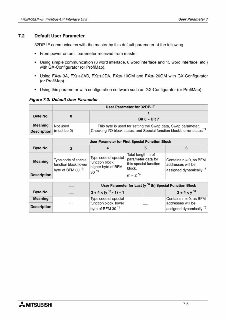
FX2N-32DP-IF Profibus-DP Interface Unit User Parameter 7
7-6
7.2 Default User Parameter
32DP-IF communicates with the master by this default parameter at the following.
• From power on until parameter received from master.
• Using simple communication (3 word interface, 6 word interface and 15 word interface, etc.)with GX-Configurator (or ProfiMap).
• Using FX0N-3A, FX2N-2AD, FX2N-2DA, FX2N-10GM and FX2N-20GM with GX-Configurator(or ProfiMap).
• Using this parameter with configuration software such as GX-Configurator (or ProfiMap).
Figure 7.3: Default User Parameter
User Parameter for 32DP-IF
Byte No. 01
Bit 0 ~ Bit 7
Meaning Not used (must be 0)
This byte is used for setting the Swap data, Swap parameter, Checking I/O block status, and Special function block’s error status.*1Description
User Parameter for First Special Function Block
Byte No. 3 4 5 6
Meaning Type code of special function block, lower
byte of BFM 30 *3
Type code of special function block, higher byte of BFM
30 *3
Total length m of parameter data for this special function block.
Contains n = 0, as BFM addresses will be
assigned dynamically *5
Description m = 2 *4
..... User Parameter for Last (y *6 th) Special Function Block
Byte No. ..... 2 + 4 ×××× (y *6 - 1) + 1 .... 2 + 4 ×××× y *6
Meaning.....
Type code of special function block, lower
byte of BFM 30 *1.....
Contains n = 0, as BFM addresses will be
assigned dynamically *5Description
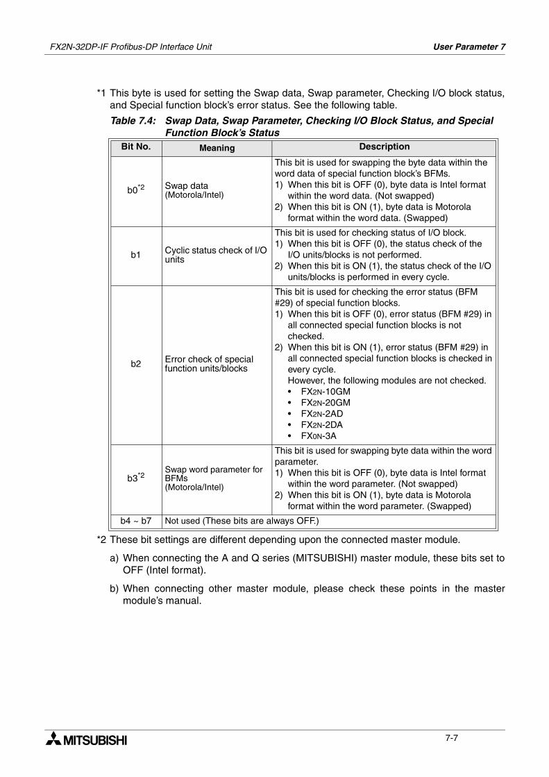
FX2N-32DP-IF Profibus-DP Interface Unit User Parameter 7
7-7
*1 This byte is used for setting the Swap data, Swap parameter, Checking I/O block status,and Special function block’s error status. See the following table.
*2 These bit settings are different depending upon the connected master module.
a) When connecting the A and Q series (MITSUBISHI) master module, these bits set toOFF (Intel format).
b) When connecting other master module, please check these points in the mastermodule’s manual.
Table 7.4: Swap Data, Swap Parameter, Checking I/O Block Status, and Special Function Block’s Status
Bit No. Meaning Description
b0*2 Swap data(Motorola/Intel)
This bit is used for swapping the byte data within the word data of special function block’s BFMs.1) When this bit is OFF (0), byte data is Intel format
within the word data. (Not swapped)2) When this bit is ON (1), byte data is Motorola
format within the word data. (Swapped)
b1 Cyclic status check of I/O units
This bit is used for checking status of I/O block.1) When this bit is OFF (0), the status check of the
I/O units/blocks is not performed.2) When this bit is ON (1), the status check of the I/O
units/blocks is performed in every cycle.
b2 Error check of special function units/blocks
This bit is used for checking the error status (BFM #29) of special function blocks.1) When this bit is OFF (0), error status (BFM #29) in
all connected special function blocks is not checked.
2) When this bit is ON (1), error status (BFM #29) in all connected special function blocks is checked in every cycle.However, the following modules are not checked.• FX2N-10GM• FX2N-20GM• FX2N-2AD• FX2N-2DA• FX0N-3A
b3*2Swap word parameter for BFMs(Motorola/Intel)
This bit is used for swapping byte data within the word parameter.1) When this bit is OFF (0), byte data is Intel format
within the word parameter. (Not swapped)2) When this bit is ON (1), byte data is Motorola
format within the word parameter. (Swapped)
b4 ~ b7 Not used (These bits are always OFF.)
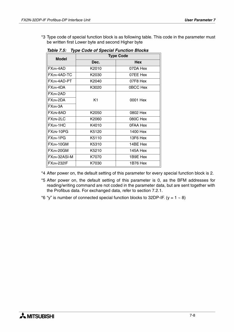
FX2N-32DP-IF Profibus-DP Interface Unit User Parameter 7
7-8
*3 Type code of special function block is as following table. This code in the parameter mustbe written first Lower byte and second Higher byte
*4 After power on, the default setting of this parameter for every special function block is 2.
*5 After power on, the default setting of this parameter is 0, as the BFM addresses forreading/writing command are not coded in the parameter data, but are sent together withthe Profibus data. For exchanged data, refer to section 7.2.1.
*6 “y” is number of connected special function blocks to 32DP-IF. (y = 1 ~ 8)
Table 7.5: Type Code of Special Function Blocks
ModelType Code
Dec. Hex
FX2N-4AD K2010 07DA Hex
FX2N-4AD-TC K2030 07EE Hex
FX2N-4AD-PT K2040 07F8 Hex
FX2N-4DA K3020 0BCC Hex
FX2N-2AD
K1 0001 HexFX2N-2DA
FX0N-3A
FX2N-8AD K2050 0802 Hex
FX2N-2LC K2060 080C Hex
FX2N-1HC K4010 0FAA Hex
FX2N-10PG K5120 1400 Hex
FX2N-1PG K5110 13F6 Hex
FX2N-10GM K5310 14BE Hex
FX2N-20GM K5210 145A Hex
FX2N-32ASI-M K7070 1B9E Hex
FX2N-232IF K7030 1B76 Hex
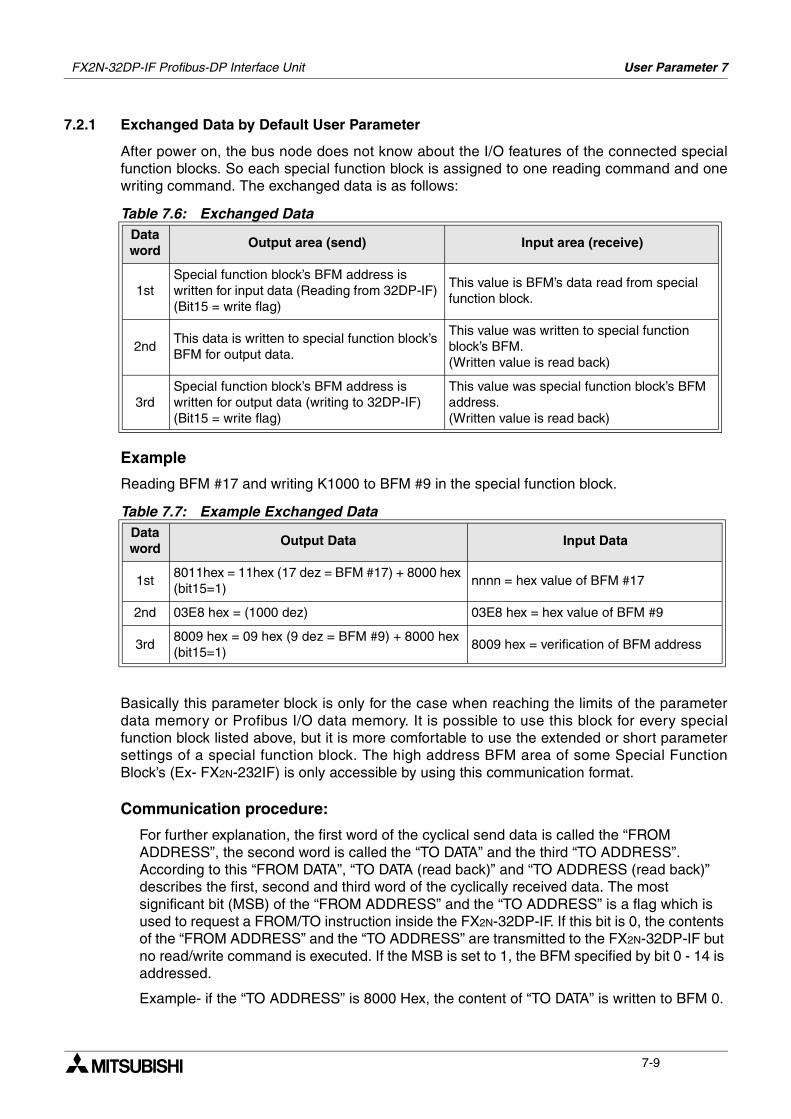
FX2N-32DP-IF Profibus-DP Interface Unit User Parameter 7
7-9
7.2.1 Exchanged Data by Default User Parameter
After power on, the bus node does not know about the I/O features of the connected specialfunction blocks. So each special function block is assigned to one reading command and onewriting command. The exchanged data is as follows:
Example
Reading BFM #17 and writing K1000 to BFM #9 in the special function block.
Basically this parameter block is only for the case when reaching the limits of the parameterdata memory or Profibus I/O data memory. It is possible to use this block for every specialfunction block listed above, but it is more comfortable to use the extended or short parametersettings of a special function block. The high address BFM area of some Special FunctionBlock’s (Ex- FX2N-232IF) is only accessible by using this communication format.
Communication procedure:
For further explanation, the first word of the cyclical send data is called the “FROM ADDRESS”, the second word is called the “TO DATA” and the third “TO ADDRESS”. According to this “FROM DATA”, “TO DATA (read back)” and “TO ADDRESS (read back)” describes the first, second and third word of the cyclically received data. The most significant bit (MSB) of the “FROM ADDRESS” and the “TO ADDRESS” is a flag which is used to request a FROM/TO instruction inside the FX2N-32DP-IF. If this bit is 0, the contents of the “FROM ADDRESS” and the “TO ADDRESS” are transmitted to the FX2N-32DP-IF but no read/write command is executed. If the MSB is set to 1, the BFM specified by bit 0 - 14 is addressed.
Example- if the “TO ADDRESS” is 8000 Hex, the content of “TO DATA” is written to BFM 0.
Table 7.6: Exchanged DataData word
Output area (send) Input area (receive)
1stSpecial function block’s BFM address is written for input data (Reading from 32DP-IF) (Bit15 = write flag)
This value is BFM’s data read from special function block.
2ndThis data is written to special function block’s BFM for output data.
This value was written to special function block’s BFM. (Written value is read back)
3rdSpecial function block’s BFM address is written for output data (writing to 32DP-IF) (Bit15 = write flag)
This value was special function block’s BFM address. (Written value is read back)
Table 7.7: Example Exchanged DataData word
Output Data Input Data
1st8011hex = 11hex (17 dez = BFM #17) + 8000 hex (bit15=1)
nnnn = hex value of BFM #17
2nd 03E8 hex = (1000 dez) 03E8 hex = hex value of BFM #9
3rd8009 hex = 09 hex (9 dez = BFM #9) + 8000 hex (bit15=1)
8009 hex = verification of BFM address
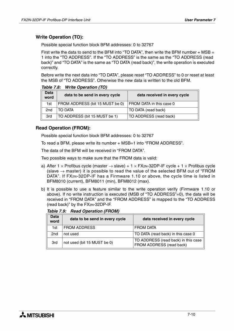
FX2N-32DP-IF Profibus-DP Interface Unit User Parameter 7
7-10
Write Operation (TO):
Possible special function block BFM addresses: 0 to 32767
First write the data to send to the BFM into “TO DATA”, then write the BFM number + MSB = 1 into the “TO ADDRESS”. If the “TO ADDRESS” is the same as the “TO ADDRESS (read back)” and “TO DATA” is the same as “TO DATA (read back)”, the write operation is executed correctly.
Before write the next data into “TO DATA”, please reset “TO ADDRESS” to 0 or reset at least the MSB of “TO ADDRESS”. Otherwise the new data is written to the old BFM.
Read Operation (FROM):
Possible special function block BFM addresses: 0 to 32767
To read a BFM, please write its number + MSB=1 into “FROM ADDRESS”.
The data of the BFM will be received in “FROM DATA”.
Two possible ways to make sure that the FROM data is valid:
a) After 1 × Profibus cycle (master → slave) + 1 × FX2N-32DP-IF cycle + 1 × Profibus cycle(slave → master) it is possible to read the value of the selected BFM out of “FROMDATA”. If FX2N-32DP-IF has a Firmware 1.10 or above, the cycle time is listed inBFM8010 (current), BFM8011 (min), BFM8012 (max).
b) It is possible to use a feature similar to the write operation verify (Firmware 1.10 orabove). If no write instruction is executed (MSB of “TO ADDRESS”=0), the data will bereceived in “FROM DATA” and the “FROM ADDRESS” is mapped to the “TO ADDRESS(read back)” by the FX2N-32DP-IF.
Table 7.8: Write Operation (TO)Data word
data to be send in every cycle data received in every cycle
1st FROM ADDRESS (bit 15 MUST be 0) FROM DATA in this case 0
2nd TO DATA TO DATA (read back)
3rd TO ADDRESS (bit 15 MUST be 1) TO ADDRESS (read back)
Table 7.9: Read Operation (FROM)Data word
data to be send in every cycle data received in every cycle
1st FROM ADDRESS FROM DATA
2nd not used TO DATA (read back) in this case 0
3rd not used (bit 15 MUST be 0)TO ADDRESS (read back) in this case FROM ADDRESS (read back)
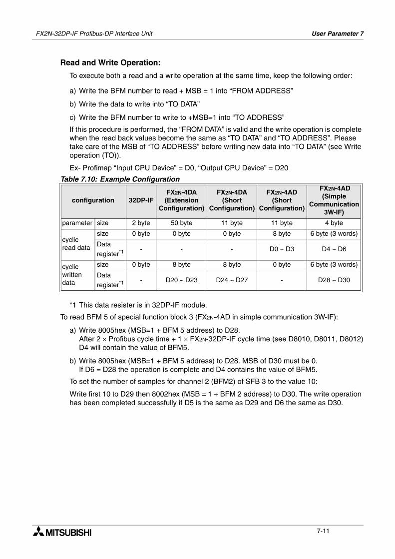
FX2N-32DP-IF Profibus-DP Interface Unit User Parameter 7
7-11
Read and Write Operation:
To execute both a read and a write operation at the same time, keep the following order:
a) Write the BFM number to read + MSB = 1 into “FROM ADDRESS”
b) Write the data to write into “TO DATA”
c) Write the BFM number to write to +MSB=1 into “TO ADDRESS”
If this procedure is performed, the “FROM DATA” is valid and the write operation is complete when the read back values become the same as “TO DATA” and “TO ADDRESS”. Please take care of the MSB of “TO ADDRESS” before writing new data into “TO DATA” (see Write operation (TO)).
Ex- Profimap “Input CPU Device” = D0, “Output CPU Device” = D20
*1 This data resister is in 32DP-IF module.
To read BFM 5 of special function block 3 (FX2N-4AD in simple communication 3W-IF):
a) Write 8005hex (MSB=1 + BFM 5 address) to D28.After 2 × Profibus cycle time + 1 × FX2N-32DP-IF cycle time (see D8010, D8011, D8012)D4 will contain the value of BFM5.
b) Write 8005hex (MSB=1 + BFM 5 address) to D28. MSB of D30 must be 0.If D6 = D28 the operation is complete and D4 contains the value of BFM5.
To set the number of samples for channel 2 (BFM2) of SFB 3 to the value 10:
Write first 10 to D29 then 8002hex (MSB = 1 + BFM 2 address) to D30. The write operation has been completed successfully if D5 is the same as D29 and D6 the same as D30.
Table 7.10: Example Configuration
configuration 32DP-IFFX2N-4DA(Extension
Configuration)
FX2N-4DA (Short
Configuration)
FX2N-4AD (Short
Configuration)
FX2N-4AD (Simple
Communication 3W-IF)
parameter size 2 byte 50 byte 11 byte 11 byte 4 byte
cyclic read data
size 0 byte 0 byte 0 byte 8 byte 6 byte (3 words)
Data
register*1- - - D0 ~ D3 D4 ~ D6
cyclic written data
size 0 byte 8 byte 8 byte 0 byte 6 byte (3 words)
Data
register*1- D20 ~ D23 D24 ~ D27 - D28 ~ D30
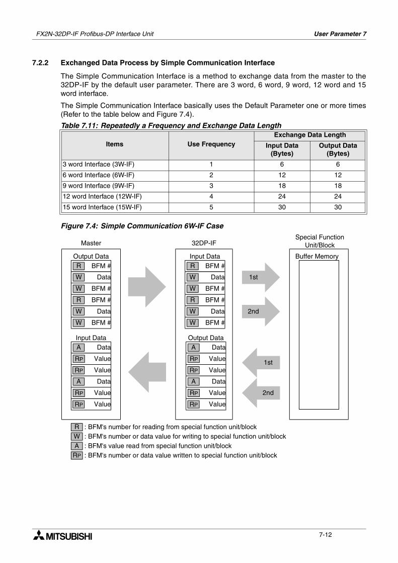
FX2N-32DP-IF Profibus-DP Interface Unit User Parameter 7
7-12
7.2.2 Exchanged Data Process by Simple Communication Interface
The Simple Communication Interface is a method to exchange data from the master to the32DP-IF by the default user parameter. There are 3 word, 6 word, 9 word, 12 word and 15word interface.
The Simple Communication Interface basically uses the Default Parameter one or more times(Refer to the table below and Figure 7.4).
Figure 7.4: Simple Communication 6W-IF Case
Table 7.11: Repeatedly a Frequency and Exchange Data Length
Items Use FrequencyExchange Data Length
Input Data(Bytes)
Output Data(Bytes)
3 word Interface (3W-IF) 1 6 6
6 word Interface (6W-IF) 2 12 12
9 word Interface (9W-IF) 3 18 18
12 word Interface (12W-IF) 4 24 24
15 word Interface (15W-IF) 5 30 30
Output DataBFM #R
DataW
BFM #W
BFM #R
DataW
BFM #W
Data
Value
Value
A
RP
RP
Data
Value
Value
A
RP
RP
Input Data
Master 32DP-IF
Buffer Memory
Special FunctionUnit/Block
Input DataBFM #R
DataW
BFM #W
BFM #R
DataW
BFM #W
Data
Value
Value
A
RP
RP
Data
Value
Value
A
RP
RP
Output Data
1st
1st
2nd
2nd
RWA
RP
: BFM's number for reading from special function unit/block: BFM's number or data value for writing to special function unit/block: BFM's value read from special function unit/block: BFM's number or data value written to special function unit/block
FX2N-32DP-IF Profibus-DP Interface Unit User Parameter 7
7-13
7.3 Configuring Slave Parameter
Caution:
The user parameter data and configuration of the 32DP-IF must always be consistent. To ensure that the user parameter data and the configuration of the 32DP-IF are matching each other, the user parameter data set should always be constructed by using the GSD file that has been delivered with the 32DP-IF.
7.3.1 Configuring Slave Parameter by GSD file
The parameter setting of the 32DP-IF can be entirely defined using the GSD file that comes onthe disk together with 32DP-IF. For an easy adjustment of all user parameter data, theMELSOFT GX-Configurator-DP (or Mitsubishi ProfiMap Software V2.x or later) (hereaftercalled “GX-Configurator-DP”) or a configuration software from another vendor which issupporting extended parameter setting should be used.
For example configuring slave parameter with ProfiMap, refer to appendix A and C.For example configuring slave parameter with GX-Configurator-DP, refer to appendix B and C.
Note:
In configuring 32DP-IF GSD file, first assign special function blocks, second extension I/O units/blocks input data, and finally extension I/O units/blocks output data. The physical placement of the modules does not have to correspond with the GSD file order. However, the special function blocks must be configured in the same order as they are connected physically to the unit.

FX2N-32DP-IF Profibus-DP Interface Unit User Parameter 7
7-14
MEMO
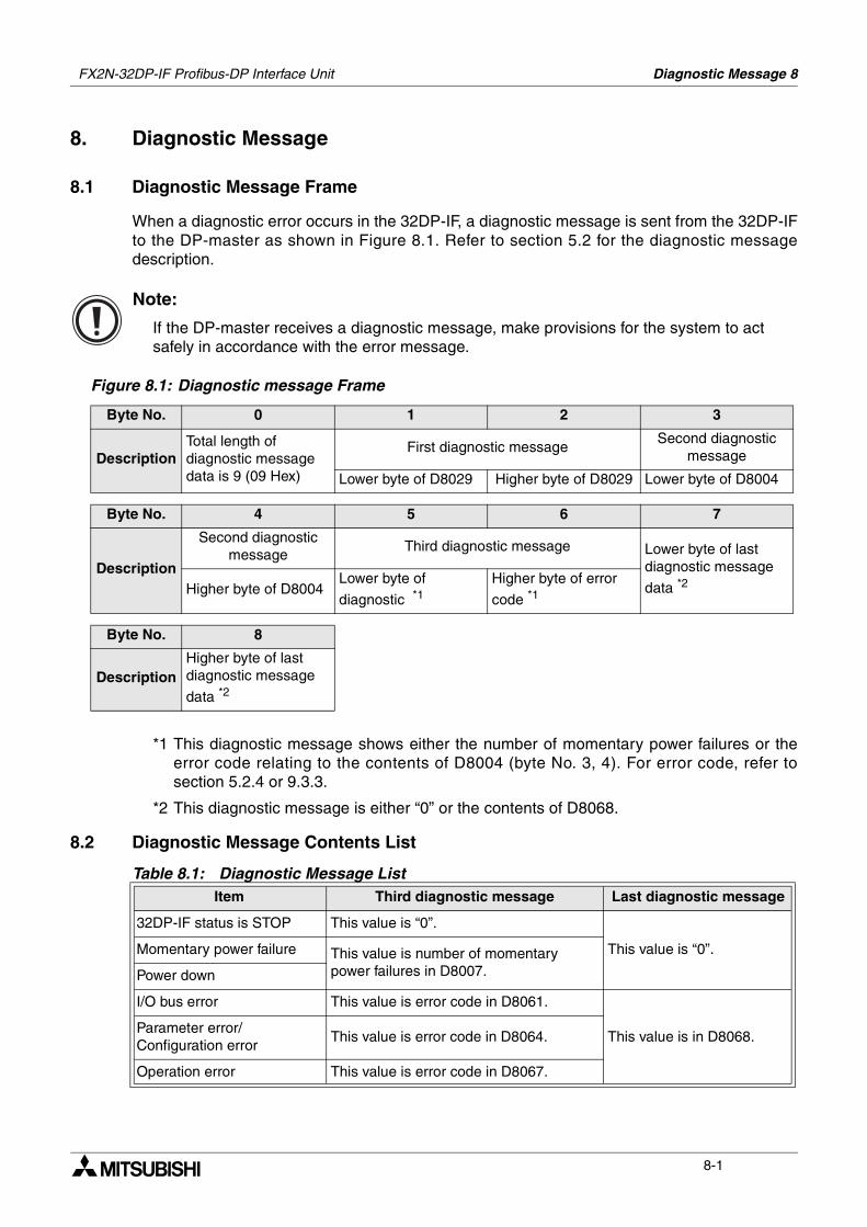
Diagnostic Message 8
8-1
8. Diagnostic Message
8.1 Diagnostic Message Frame
When a diagnostic error occurs in the 32DP-IF, a diagnostic message is sent from the 32DP-IFto the DP-master as shown in Figure 8.1. Refer to section 5.2 for the diagnostic messagedescription.
Note:
If the DP-master receives a diagnostic message, make provisions for the system to act safely in accordance with the error message.
Figure 8.1: Diagnostic message Frame
*1 This diagnostic message shows either the number of momentary power failures or theerror code relating to the contents of D8004 (byte No. 3, 4). For error code, refer tosection 5.2.4 or 9.3.3.
*2 This diagnostic message is either “0” or the contents of D8068.
8.2 Diagnostic Message Contents List
Byte No. 0 1 2 3
DescriptionTotal length of diagnostic message data is 9 (09 Hex)
First diagnostic messageSecond diagnostic
message
Lower byte of D8029 Higher byte of D8029 Lower byte of D8004
Byte No. 4 5 6 7
Description
Second diagnostic message
Third diagnostic message Lower byte of last diagnostic message
data *2Higher byte of D8004Lower byte of
diagnostic *1Higher byte of error
code *1
Byte No. 8
DescriptionHigher byte of last diagnostic message
data *2
Table 8.1: Diagnostic Message ListItem Third diagnostic message Last diagnostic message
32DP-IF status is STOP This value is “0”.
This value is “0”.Momentary power failure This value is number of momentary power failures in D8007.Power down
I/O bus error This value is error code in D8061.
This value is in D8068.Parameter error/ Configuration error
This value is error code in D8064.
Operation error This value is error code in D8067.
FX2N-32DP-IF Profibus-DP Interface Unit

FX2N-32DP-IF Profibus-DP Interface Unit Diagnostic Message 8
8-2
MEMO
Diagnostics 9
9-1
9. Diagnostics
9.1 Preliminary Checks
1) Check “POWER LED”. If this is OFF, please see section 9.2.
2) Check power supply for special function blocks and extension I/O units/blocks.If this can not be supplied, 32DP-IF will not operate correctly.
3) Check that the slave addresses are the same at the 32DP-IF and in the DP-masterconfiguration. If the slave addresses are not the same in the 32DP-IF and in the DP-master,change these addresses to match in both modules.
4) Check that the parameter data of 32DP-IF are set correctly in the DP-master. If the parameter data of the 32DP-IF are not set correctly in the DP-master, communicationover the Profibus-DP network may be affected.
5) Check whether the network wiring and/or the cables for the extension blocks/units areproperly connected to the 32DP-IF.
6) Check that the system configuration rules have not been exceeded, i.e. the number ofspecial function blocks does not exceed 8 and control I/O of 32DP-IF is 256 or less.
7) Put RUN/STOP switch on the 32DP-IF into RUN.
FX2N-32DP-IF Profibus-DP Interface Unit
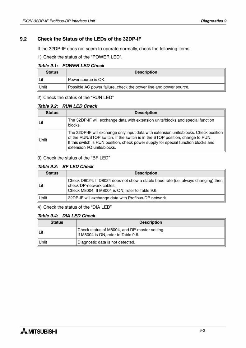
FX2N-32DP-IF Profibus-DP Interface Unit Diagnostics 9
9-2
9.2 Check the Status of the LEDs of the 32DP-IF
If the 32DP-IF does not seem to operate normally, check the following items.
1) Check the status of the “POWER LED”.
2) Check the status of the “RUN LED”
3) Check the status of the “BF LED”
4) Check the status of the “DIA LED”
Table 9.1: POWER LED CheckStatus Description
Lit Power source is OK.
Unlit Possible AC power failure, check the power line and power source.
Table 9.2: RUN LED CheckStatus Description
LitThe 32DP-IF will exchange data with extension units/blocks and special function blocks.
Unlit
The 32DP-IF will exchange only input data with extension units/blocks. Check position of the RUN/STOP switch. If the switch is in the STOP position, change to RUN.If this switch is RUN position, check power supply for special function blocks and extension I/O units/blocks.
Table 9.3: BF LED CheckStatus Description
LitCheck D8024. If D8024 does not show a stable baud rate (i.e. always changing) then check DP-network cables. Check M8004. If M8004 is ON, refer to Table 9.6.
Unlit 32DP-IF will exchange data with Profibus-DP network.
Table 9.4: DIA LED CheckStatus Description
LitCheck status of M8004, and DP-master setting.If M8004 is ON, refer to Table 9.6.
Unlit Diagnostic data is not detected.
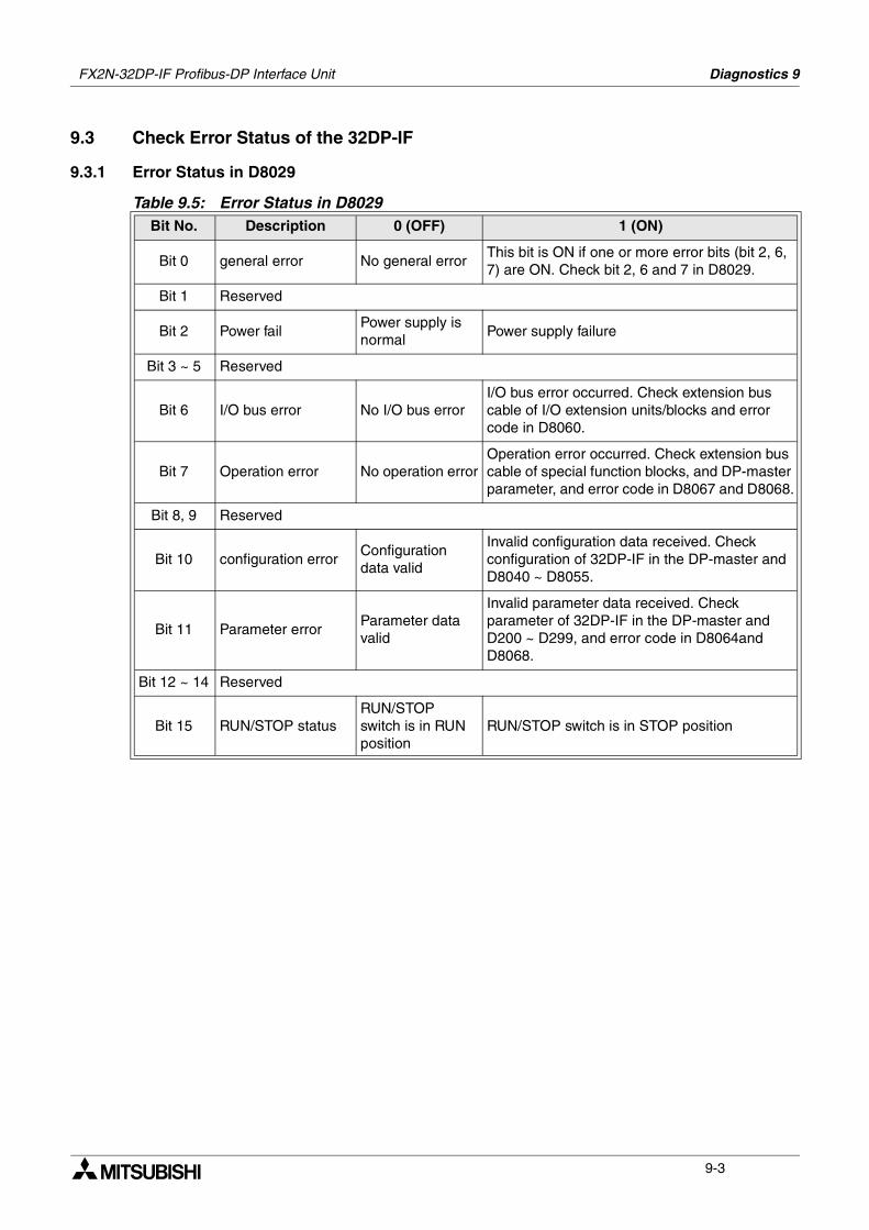
FX2N-32DP-IF Profibus-DP Interface Unit Diagnostics 9
9-3
9.3 Check Error Status of the 32DP-IF
9.3.1 Error Status in D8029
Table 9.5: Error Status in D8029Bit No. Description 0 (OFF) 1 (ON)
Bit 0 general error No general errorThis bit is ON if one or more error bits (bit 2, 6, 7) are ON. Check bit 2, 6 and 7 in D8029.
Bit 1 Reserved
Bit 2 Power failPower supply is normal
Power supply failure
Bit 3 ~ 5 Reserved
Bit 6 I/O bus error No I/O bus errorI/O bus error occurred. Check extension bus cable of I/O extension units/blocks and error code in D8060.
Bit 7 Operation error No operation errorOperation error occurred. Check extension bus cable of special function blocks, and DP-master parameter, and error code in D8067 and D8068.
Bit 8, 9 Reserved
Bit 10 configuration errorConfiguration data valid
Invalid configuration data received. Check configuration of 32DP-IF in the DP-master and D8040 ~ D8055.
Bit 11 Parameter errorParameter data valid
Invalid parameter data received. Check parameter of 32DP-IF in the DP-master and D200 ~ D299, and error code in D8064and D8068.
Bit 12 ~ 14 Reserved
Bit 15 RUN/STOP statusRUN/STOP switch is in RUN position
RUN/STOP switch is in STOP position
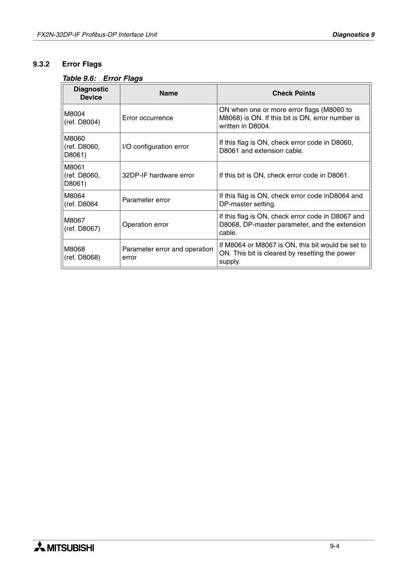
FX2N-32DP-IF Profibus-DP Interface Unit Diagnostics 9
9-4
9.3.2 Error Flags
Table 9.6: Error FlagsDiagnostic
DeviceName Check Points
M8004(ref. D8004)
Error occurrenceON when one or more error flags (M8060 to M8068) is ON. If this bit is ON, error number is written in D8004.
M8060(ref. D8060, D8061)
I/O configuration errorIf this flag is ON, check error code in D8060, D8061 and extension cable.
M8061(ref. D8060, D8061)
32DP-IF hardware error If this bit is ON, check error code in D8061.
M8064(ref. D8064
Parameter errorIf this flag is ON, check error code inD8064 and DP-master setting.
M8067(ref. D8067)
Operation errorIf this flag is ON, check error code in D8067 and D8068, DP-master parameter, and the extension cable.
M8068(ref. D8068)
Parameter error and operation error
If M8064 or M8067 is ON, this bit would be set to ON. This bit is cleared by resetting the power supply.
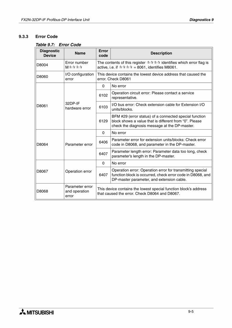
FX2N-32DP-IF Profibus-DP Interface Unit Diagnostics 9
9-5
9.3.3 Error Code
Table 9.7: Error CodeDiagnostic
DeviceName
Error code
Description
D8004Error number M
The contents of this register identifies which error flag is active, i.e. if = 8061, identifies M8061.
D8060I/O configuration error
This device contains the lowest device address that caused the error. Check D8061
D806132DP-IF hardware error
0 No error
6102Operation circuit error: Please contact a service representative.
6103I/O bus error: Check extension cable for Extension I/O units/blocks.
6129BFM #29 (error status) of a connected special function block shows a value that is different from “0”. Please check the diagnosis message at the DP-master.
D8064 Parameter error
0 No error
6406Parameter error for extension units/blocks: Check error code in D8068, and parameter in the DP-master.
6407Parameter length error: Parameter data too long, check parameter’s length in the DP-master.
D8067 Operation error
0 No error
6407Operation error: Operation error for transmitting special function block is occurred, check error code in D8068, and DP-master parameter, and extension cable.
D8068Parameter error and operation error
This device contains the lowest special function block’s address that caused the error. Check D8064 and D8067.

FX2N-32DP-IF Profibus-DP Interface Unit Diagnostics 9
9-6
MEMO
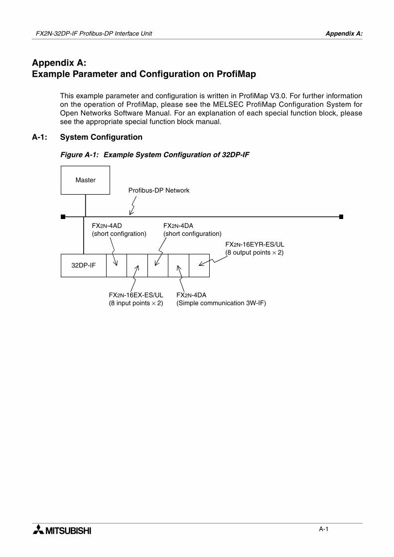
Appendix A:
A-1
Appendix A:Example Parameter and Configuration on ProfiMap
This example parameter and configuration is written in ProfiMap V3.0. For further informationon the operation of ProfiMap, please see the MELSEC ProfiMap Configuration System forOpen Networks Software Manual. For an explanation of each special function block, pleasesee the appropriate special function block manual.
A-1: System Configuration
Figure A-1: Example System Configuration of 32DP-IF
Master
32DP-IF
FX2N-4AD(short configration)
FX2N-4DA(short configuration)
FX2N-16EX-ES/UL(8 input points × 2)
FX2N-16EYR-ES/UL(8 output points × 2)
Profibus-DP Network
FX2N-4DA(Simple communication 3W-IF)
FX2N-32DP-IF Profibus-DP Interface Unit
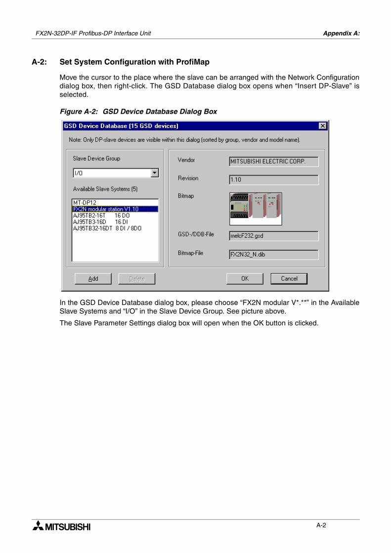
FX2N-32DP-IF Profibus-DP Interface Unit Appendix A:
A-2
A-2: Set System Configuration with ProfiMap
Move the cursor to the place where the slave can be arranged with the Network Configurationdialog box, then right-click. The GSD Database dialog box opens when “Insert DP-Slave” isselected.
Figure A-2: GSD Device Database Dialog Box
In the GSD Device Database dialog box, please choose “FX2N modular V*.**” in the AvailableSlave Systems and “I/O” in the Slave Device Group. See picture above.
The Slave Parameter Settings dialog box will open when the OK button is clicked.
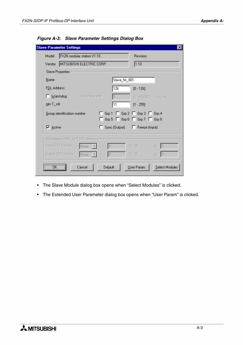
FX2N-32DP-IF Profibus-DP Interface Unit Appendix A:
A-3
Figure A-3: Slave Parameter Settings Dialog Box
• The Slave Module dialog box opens when “Select Modules” is clicked.
• The Extended User Parameter dialog box opens when “User Param” is clicked.
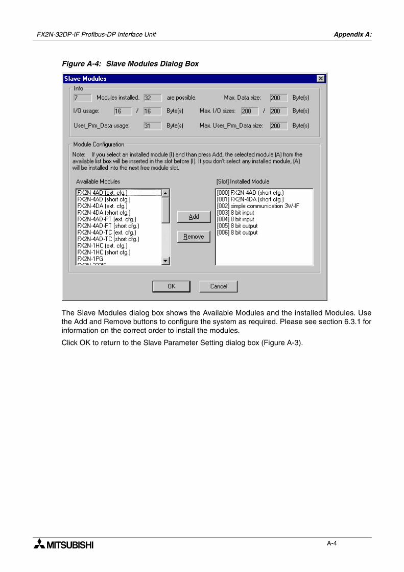
FX2N-32DP-IF Profibus-DP Interface Unit Appendix A:
A-4
Figure A-4: Slave Modules Dialog Box
The Slave Modules dialog box shows the Available Modules and the installed Modules. Usethe Add and Remove buttons to configure the system as required. Please see section 6.3.1 forinformation on the correct order to install the modules.
Click OK to return to the Slave Parameter Setting dialog box (Figure A-3).
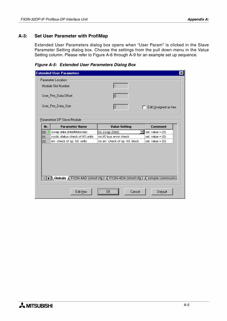
FX2N-32DP-IF Profibus-DP Interface Unit Appendix A:
A-5
A-3: Set User Parameter with ProfiMap
Extended User Parameters dialog box opens when “User Param” is clicked in the SlaveParameter Setting dialog box. Choose the settings from the pull down menu in the ValueSetting column. Please refer to Figure A-6 through A-9 for an example set up sequence.
Figure A-5: Extended User Parameters Dialog Box
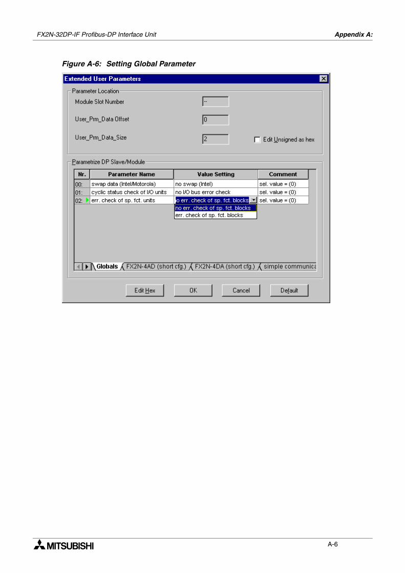
FX2N-32DP-IF Profibus-DP Interface Unit Appendix A:
A-6
Figure A-6: Setting Global Parameter
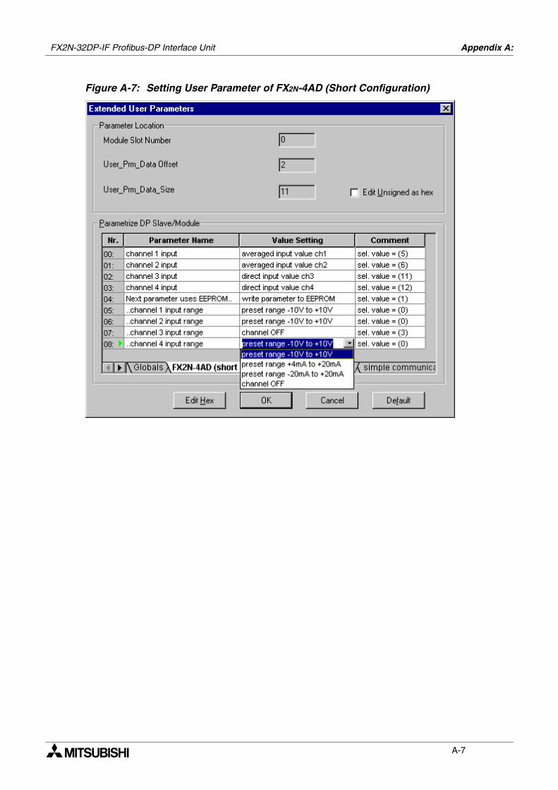
FX2N-32DP-IF Profibus-DP Interface Unit Appendix A:
A-7
Figure A-7: Setting User Parameter of FX2N-4AD (Short Configuration)
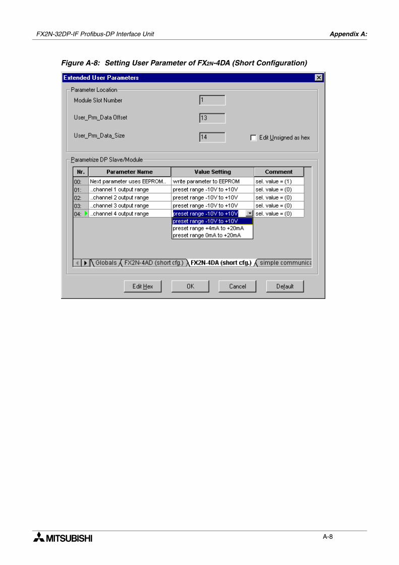
FX2N-32DP-IF Profibus-DP Interface Unit Appendix A:
A-8
Figure A-8: Setting User Parameter of FX2N-4DA (Short Configuration)
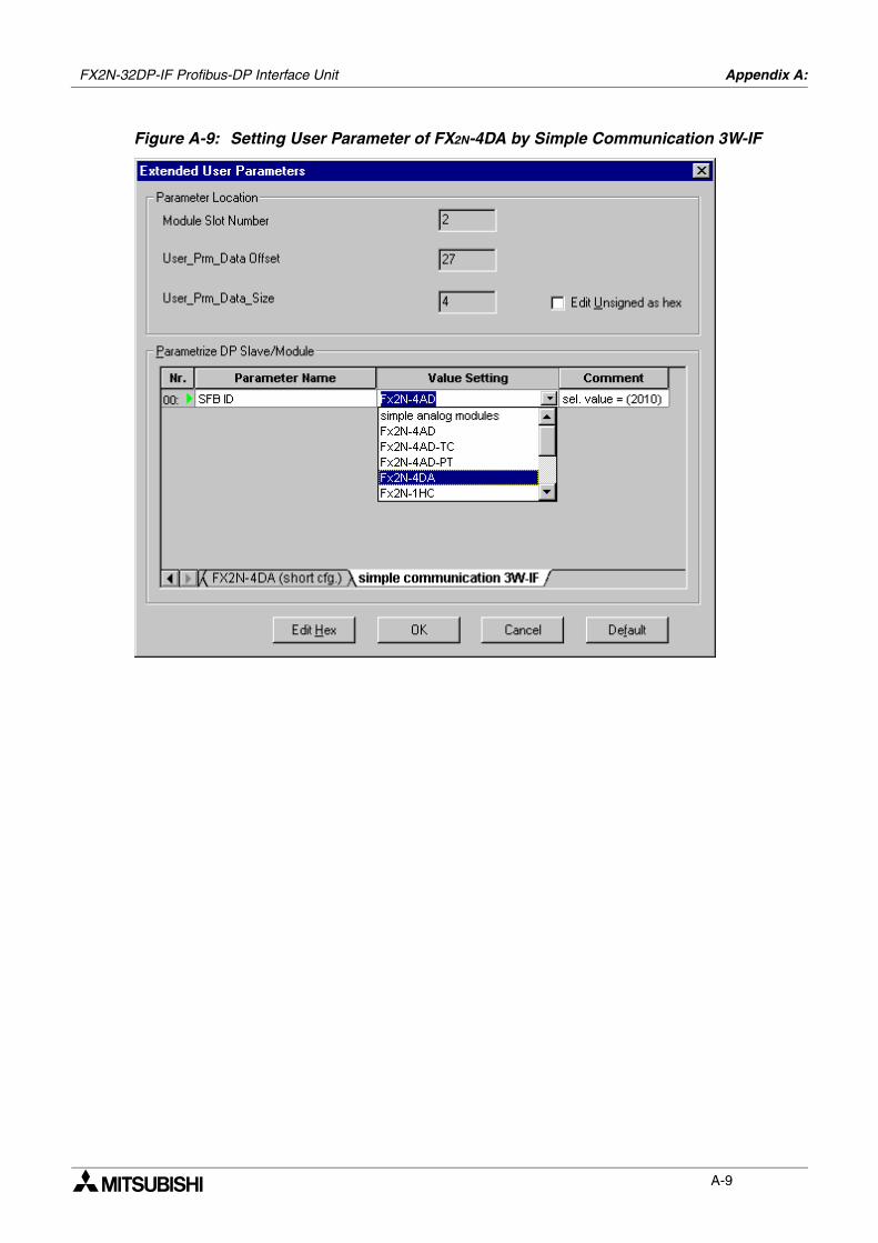
FX2N-32DP-IF Profibus-DP Interface Unit Appendix A:
A-9
Figure A-9: Setting User Parameter of FX2N-4DA by Simple Communication 3W-IF

FX2N-32DP-IF Profibus-DP Interface Unit Appendix A:
A-10
MEMO
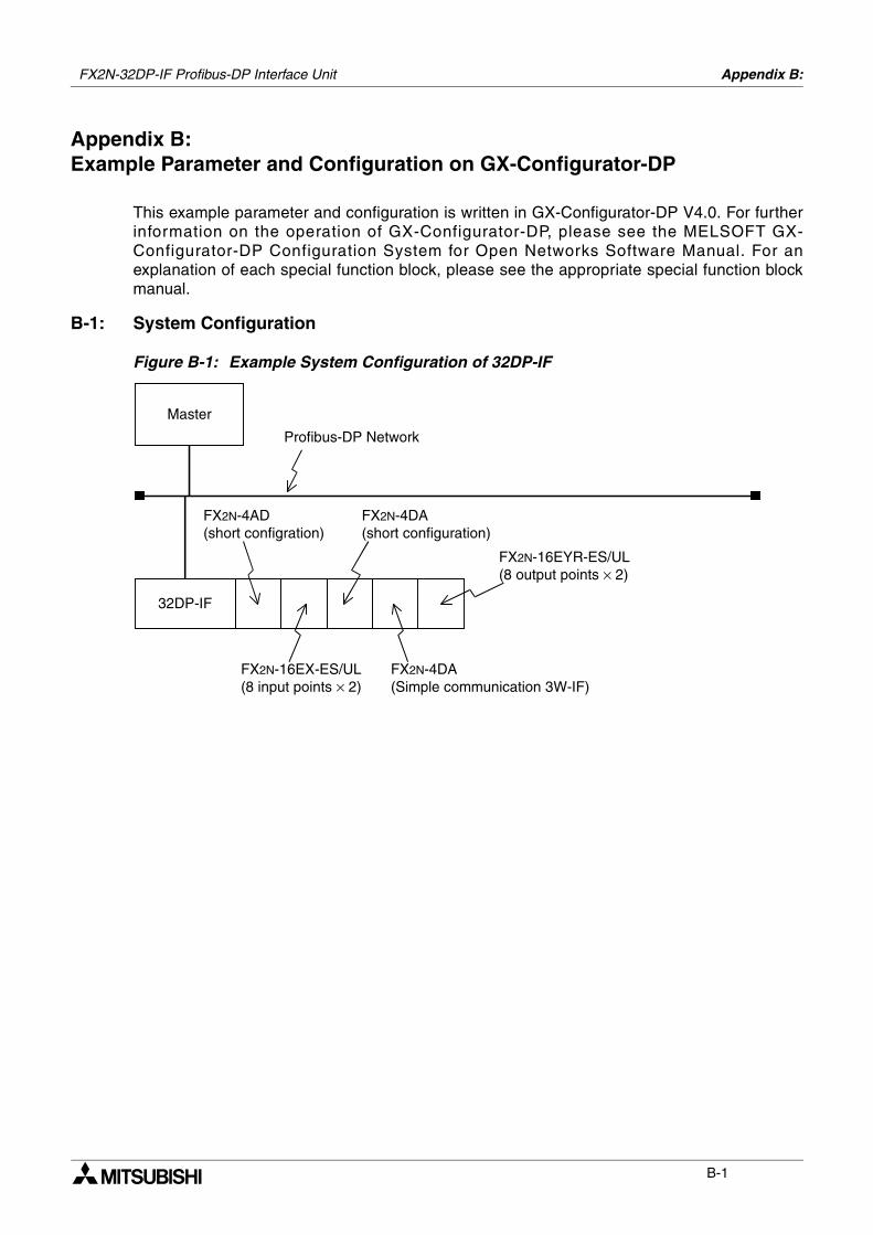
Appendix B:
B-1
Appendix B:Example Parameter and Configuration on GX-Configurator-DP
This example parameter and configuration is written in GX-Configurator-DP V4.0. For furtherinformation on the operation of GX-Configurator-DP, please see the MELSOFT GX-Configurator-DP Configuration System for Open Networks Software Manual. For anexplanation of each special function block, please see the appropriate special function blockmanual.
B-1: System Configuration
Figure B-1: Example System Configuration of 32DP-IF
Master
32DP-IF
FX2N-4AD(short configration)
FX2N-4DA(short configuration)
FX2N-16EX-ES/UL(8 input points × 2)
FX2N-16EYR-ES/UL(8 output points × 2)
Profibus-DP Network
FX2N-4DA(Simple communication 3W-IF)
FX2N-32DP-IF Profibus-DP Interface Unit
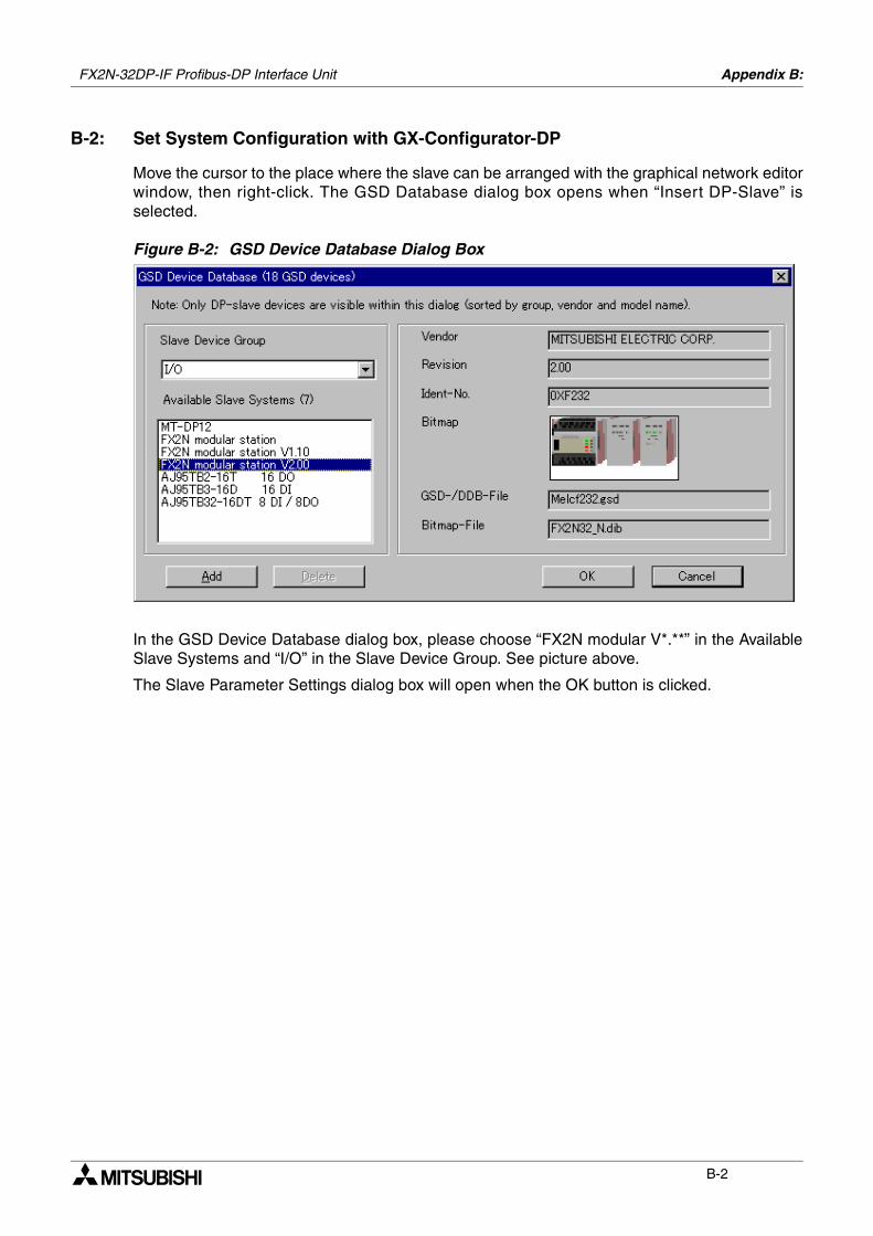
FX2N-32DP-IF Profibus-DP Interface Unit Appendix B:
B-2
B-2: Set System Configuration with GX-Configurator-DP
Move the cursor to the place where the slave can be arranged with the graphical network editorwindow, then right-click. The GSD Database dialog box opens when “Insert DP-Slave” isselected.
Figure B-2: GSD Device Database Dialog Box
In the GSD Device Database dialog box, please choose “FX2N modular V*.**” in the AvailableSlave Systems and “I/O” in the Slave Device Group. See picture above.
The Slave Parameter Settings dialog box will open when the OK button is clicked.
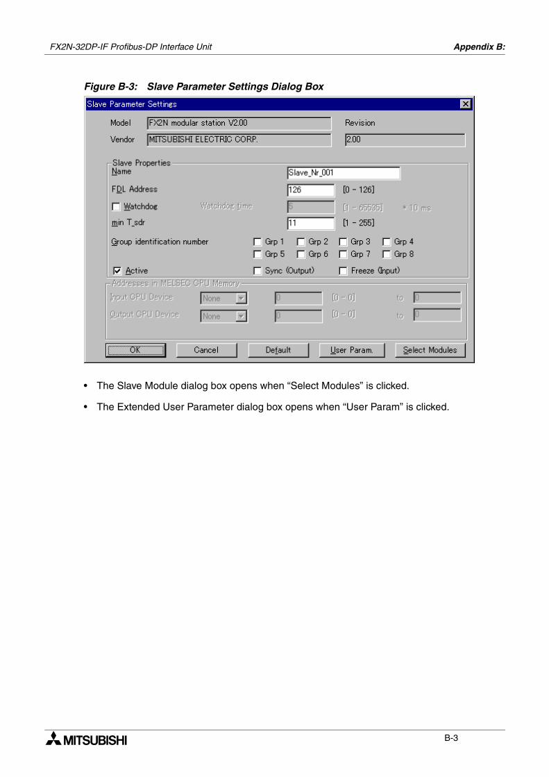
FX2N-32DP-IF Profibus-DP Interface Unit Appendix B:
B-3
Figure B-3: Slave Parameter Settings Dialog Box
• The Slave Module dialog box opens when “Select Modules” is clicked.
• The Extended User Parameter dialog box opens when “User Param” is clicked.
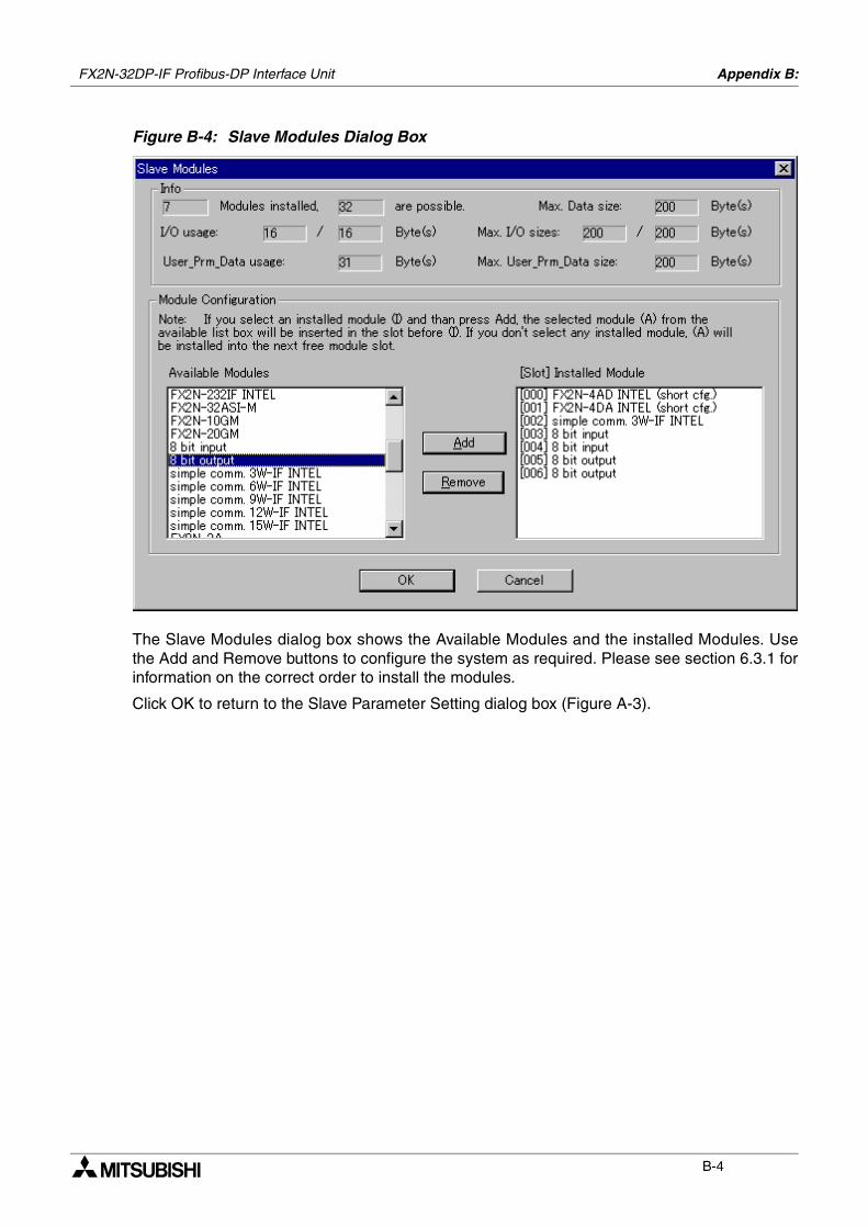
FX2N-32DP-IF Profibus-DP Interface Unit Appendix B:
B-4
Figure B-4: Slave Modules Dialog Box
The Slave Modules dialog box shows the Available Modules and the installed Modules. Usethe Add and Remove buttons to configure the system as required. Please see section 6.3.1 forinformation on the correct order to install the modules.
Click OK to return to the Slave Parameter Setting dialog box (Figure A-3).
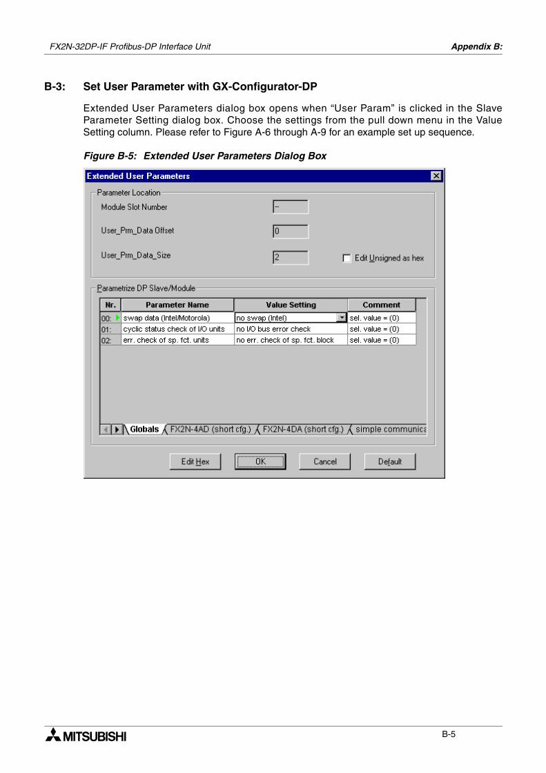
FX2N-32DP-IF Profibus-DP Interface Unit Appendix B:
B-5
B-3: Set User Parameter with GX-Configurator-DP
Extended User Parameters dialog box opens when “User Param” is clicked in the SlaveParameter Setting dialog box. Choose the settings from the pull down menu in the ValueSetting column. Please refer to Figure A-6 through A-9 for an example set up sequence.
Figure B-5: Extended User Parameters Dialog Box
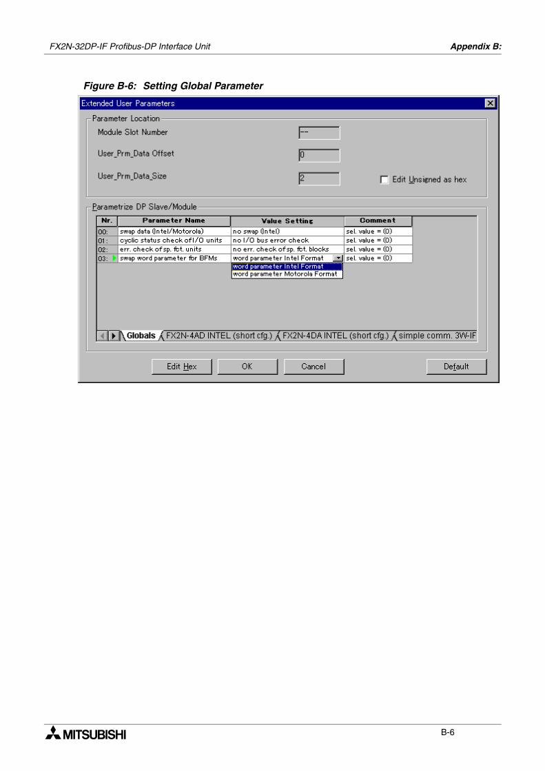
FX2N-32DP-IF Profibus-DP Interface Unit Appendix B:
B-6
Figure B-6: Setting Global Parameter
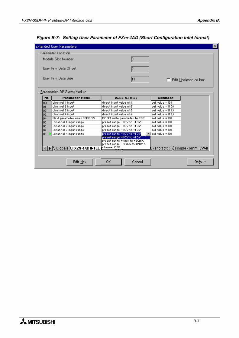
FX2N-32DP-IF Profibus-DP Interface Unit Appendix B:
B-7
Figure B-7: Setting User Parameter of FX2N-4AD (Short Configuration Intel format)
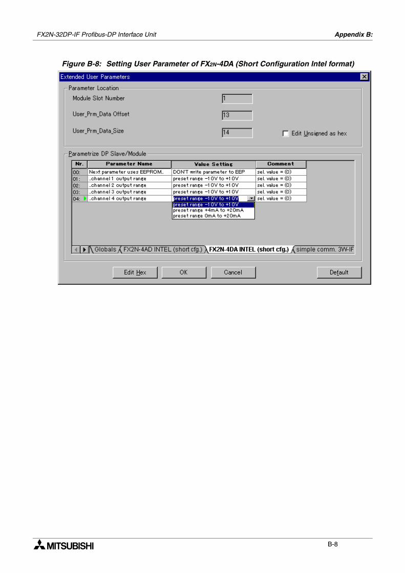
FX2N-32DP-IF Profibus-DP Interface Unit Appendix B:
B-8
Figure B-8: Setting User Parameter of FX2N-4DA (Short Configuration Intel format)
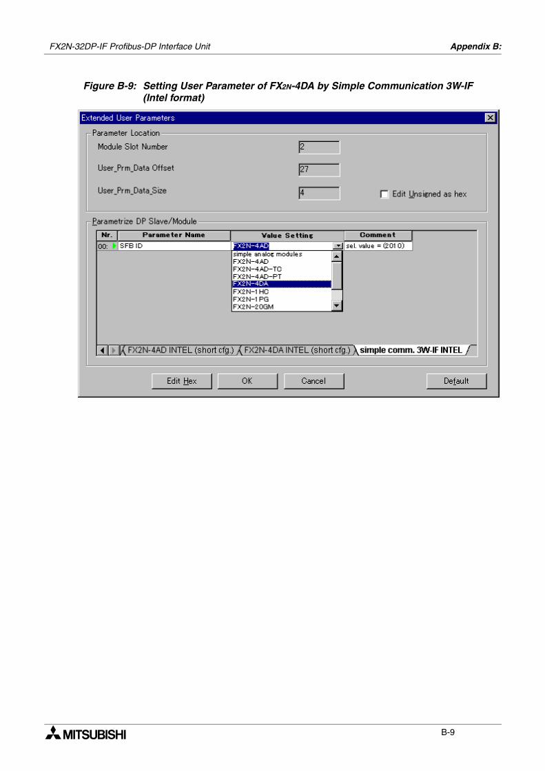
FX2N-32DP-IF Profibus-DP Interface Unit Appendix B:
B-9
Figure B-9: Setting User Parameter of FX2N-4DA by Simple Communication 3W-IF(Intel format)

FX2N-32DP-IF Profibus-DP Interface Unit Appendix B:
B-10
MEMO
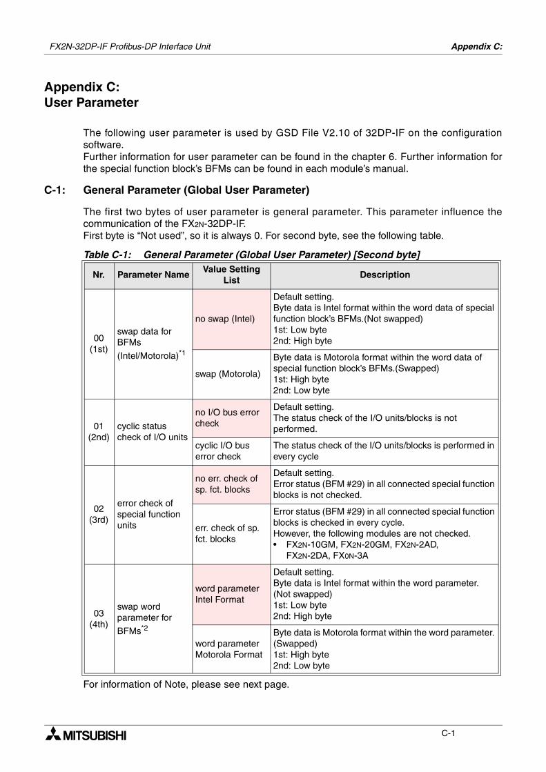
Appendix C:
C-1
Appendix C:User Parameter
The following user parameter is used by GSD File V2.10 of 32DP-IF on the configurationsoftware. Further information for user parameter can be found in the chapter 6. Further information forthe special function block’s BFMs can be found in each module’s manual.
C-1: General Parameter (Global User Parameter)
The first two bytes of user parameter is general parameter. This parameter influence thecommunication of the FX2N-32DP-IF. First byte is “Not used”, so it is always 0. For second byte, see the following table.
For information of Note, please see next page.
Table C-1: General Parameter (Global User Parameter) [Second byte]
Nr. Parameter NameValue Setting
ListDescription
00(1st)
swap data for BFMs
(Intel/Motorola)*1
no swap (Intel)
Default setting.Byte data is Intel format within the word data of special function block’s BFMs.(Not swapped)1st: Low byte2nd: High byte
swap (Motorola)
Byte data is Motorola format within the word data of special function block’s BFMs.(Swapped)1st: High byte2nd: Low byte
01(2nd)
cyclic status check of I/O units
no I/O bus error check
Default setting.The status check of the I/O units/blocks is not performed.
cyclic I/O bus error check
The status check of the I/O units/blocks is performed in every cycle
02(3rd)
error check of special function units
no err. check of sp. fct. blocks
Default setting.Error status (BFM #29) in all connected special function blocks is not checked.
err. check of sp. fct. blocks
Error status (BFM #29) in all connected special function blocks is checked in every cycle.However, the following modules are not checked.• FX2N-10GM, FX2N-20GM, FX2N-2AD,
FX2N-2DA, FX0N-3A
03(4th)
swap word parameter for
BFMs*2
word parameter Intel Format
Default setting.Byte data is Intel format within the word parameter. (Not swapped)1st: Low byte2nd: High byte
word parameter Motorola Format
Byte data is Motorola format within the word parameter. (Swapped)1st: High byte2nd: Low byte
FX2N-32DP-IF Profibus-DP Interface Unit

FX2N-32DP-IF Profibus-DP Interface Unit Appendix C:
C-2
*1 These bit settings are different depending upon the connected master module.
a) When connecting the A and Q series (MITSUBISHI) master module, both units areset to Intel format.
b) When connecting other master module, please check the settings in the mastermodule’s manual.
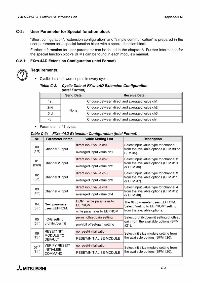
FX2N-32DP-IF Profibus-DP Interface Unit Appendix C:
C-3
C-2: User Parameter for Special function block
“Short configuration”, “extension configuration” and “simple communication” is prepared in theuser parameter for a special function block with a special function block.
Further information for user parameter can be found in the chapter 6. Further information forthe special function block’s BFMs can be found in each module’s manual.
C-2-1: FX2N-4AD Extension Configuration (Intel Format)
Requirements:
• Cyclic data is 4 word inputs in every cycle.
• Parameter is 41 bytes.
Table C-2: Cyclic Data of FX2N-4AD Extension Configuration(Intel Format)
Send Data Receive Data
1st
None
Choose between direct and averaged value ch1
2nd Choose between direct and averaged value ch2
3rd Choose between direct and averaged value ch3
4th Choose between direct and averaged value ch4
Table C-3: FX2N-4AD Extension Configuration (Intel Format)Nr. Parameter Name Value Setting List Description
00(1st)
Channel 1 inputdirect input value ch1 Select input value type for channel 1
from the available options (BFM #9 or BFM #5).averaged input value ch1
01(2nd)
Channel 2 inputdirect input value ch2 Select input value type for channel 2
from the available options (BFM #10 or BFM #6).averaged input value ch2
02(3rd)
Channel 3 inputdirect input value ch3 Select input value type for channel 3
from the available options (BFM #11 or BFM #7).averaged input value ch3
03(4th)
Channel 4 inputdirect input value ch4 Select input value type for channel 4
from the available options (BFM #12 or BFM #8).averaged input value ch4
04(5th)
Next parameter uses EEPROM.
DON'T write parameter to EEPROM
The 6th parameter uses EEPROM. Select “writing to EEPROM” setting from the available options.write parameter to EEPROM
05(6th)
..O/G setting prohibit/permit
permit offset/gain setting Select prohibit/permit setting of offset/gain from the available options (BFM #21).prohibit offset/gain setting
06(7th)
RESET/INIT. MODULE TO DEFAULT
no reset/initialisationSelect initialize module setting from the available options (BFM #20).RESET/INITIALISE MODULE
07*1
(8th)
VERIFY RESET/INITIALISE COMMAND
no reset/initialisationSelect initialize module setting from the available options (BFM #20).RESET/INITIALISE MODULE
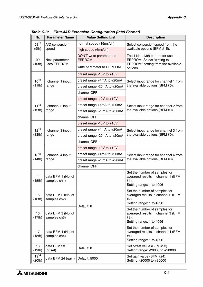
FX2N-32DP-IF Profibus-DP Interface Unit Appendix C:
C-4
08*2
(9th)A/D conversion speed
normal speed (15ms/ch) Select conversion speed from the available options (BFM #15).high speed (6ms/ch)
09(10th)
Next parameter uses EEPROM.
DON'T write parameter to EEPROM
The 11th ~13th parameter use EEPROM. Select “writing to EEPROM” setting from the available options.write parameter to EEPROM
10*3
(11th)..channel 1 input range
preset range -10V to +10V
Select input range for channel 1 from the available options (BFM #0).
preset range +4mA to +20mA
preset range -20mA to +20mA
channel OFF
11*3
(12th)..channel 2 input range
preset range -10V to +10V
Select input range for channel 2 from the available options (BFM #0).
preset range +4mA to +20mA
preset range -20mA to +20mA
channel OFF
12*3
(13th)..channel 3 input range
preset range -10V to +10V
Select input range for channel 3 from the available options (BFM #0).
preset range +4mA to +20mA
preset range -20mA to +20mA
channel OFF
13*3
(14th)..channel 4 input range
preset range -10V to +10V
Select input range for channel 4 from the available options (BFM #0).
preset range +4mA to +20mA
preset range -20mA to +20mA
channel OFF
14(15th)
data BFM 1 (No. of samples ch1)
Default: 8
Set the number of samples for averaged results in channel 1 (BFM #1).Setting range: 1 to 4096
15(16th)
data BFM 2 (No. of samples ch2)
Set the number of samples for averaged results in channel 2 (BFM #2).Setting range: 1 to 4096
16(17th)
data BFM 3 (No. of samples ch3)
Set the number of samples for averaged results in channel 3 (BFM #3).Setting range: 1 to 4096
17(18th)
data BFM 4 (No. of samples ch4)
Set the number of samples for averaged results in channel 4 (BFM #4).Setting range: 1 to 4096
18(19th)
data BFM 23 (offset)
Default: 0Set offset value (BFM #23).Setting range: -20000 to +20000
19*4
(20th)data BFM 24 (gain) Default: 5000
Set gain value (BFM #24).Setting: -20000 to +20000
Table C-3: FX2N-4AD Extension Configuration (Intel Format)Nr. Parameter Name Value Setting List Description
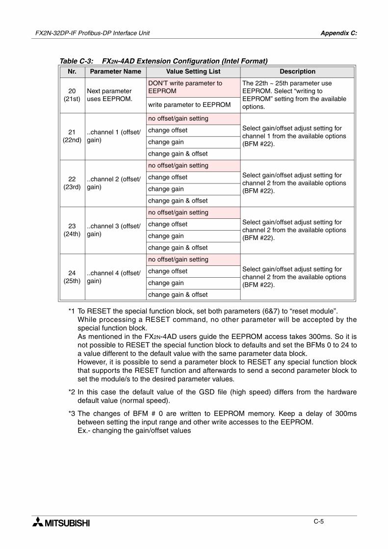
FX2N-32DP-IF Profibus-DP Interface Unit Appendix C:
C-5
*1 To RESET the special function block, set both parameters (6&7) to “reset module”.While processing a RESET command, no other parameter will be accepted by thespecial function block.As mentioned in the FX2N-4AD users guide the EEPROM access takes 300ms. So it isnot possible to RESET the special function block to defaults and set the BFMs 0 to 24 toa value different to the default value with the same parameter data block.However, it is possible to send a parameter block to RESET any special function blockthat supports the RESET function and afterwards to send a second parameter block toset the module/s to the desired parameter values.
*2 In this case the default value of the GSD file (high speed) differs from the hardwaredefault value (normal speed).
*3 The changes of BFM # 0 are written to EEPROM memory. Keep a delay of 300msbetween setting the input range and other write accesses to the EEPROM.Ex.- changing the gain/offset values
20(21st)
Next parameter uses EEPROM.
DON'T write parameter to EEPROM
The 22th ~ 25th parameter use EEPROM. Select “writing to EEPROM” setting from the available options.write parameter to EEPROM
21(22nd)
..channel 1 (offset/gain)
no offset/gain setting
Select gain/offset adjust setting for channel 1 from the available options (BFM #22).
change offset
change gain
change gain & offset
22(23rd)
..channel 2 (offset/gain)
no offset/gain setting
Select gain/offset adjust setting for channel 2 from the available options (BFM #22).
change offset
change gain
change gain & offset
23(24th)
..channel 3 (offset/gain)
no offset/gain setting
Select gain/offset adjust setting for channel 2 from the available options (BFM #22).
change offset
change gain
change gain & offset
24(25th)
..channel 4 (offset/gain)
no offset/gain setting
Select gain/offset adjust setting for channel 2 from the available options (BFM #22).
change offset
change gain
change gain & offset
Table C-3: FX2N-4AD Extension Configuration (Intel Format)Nr. Parameter Name Value Setting List Description
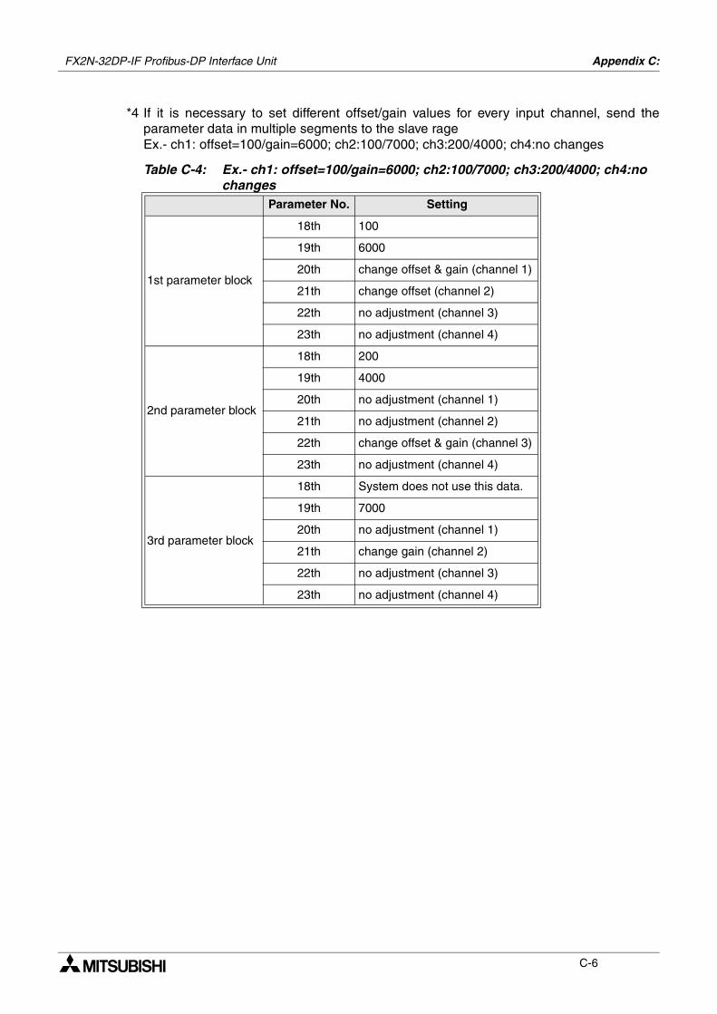
FX2N-32DP-IF Profibus-DP Interface Unit Appendix C:
C-6
*4 If it is necessary to set different offset/gain values for every input channel, send theparameter data in multiple segments to the slave rageEx.- ch1: offset=100/gain=6000; ch2:100/7000; ch3:200/4000; ch4:no changes
Table C-4: Ex.- ch1: offset=100/gain=6000; ch2:100/7000; ch3:200/4000; ch4:no changes
Parameter No. Setting
1st parameter block
18th 100
19th 6000
20th change offset & gain (channel 1)
21th change offset (channel 2)
22th no adjustment (channel 3)
23th no adjustment (channel 4)
2nd parameter block
18th 200
19th 4000
20th no adjustment (channel 1)
21th no adjustment (channel 2)
22th change offset & gain (channel 3)
23th no adjustment (channel 4)
3rd parameter block
18th System does not use this data.
19th 7000
20th no adjustment (channel 1)
21th change gain (channel 2)
22th no adjustment (channel 3)
23th no adjustment (channel 4)
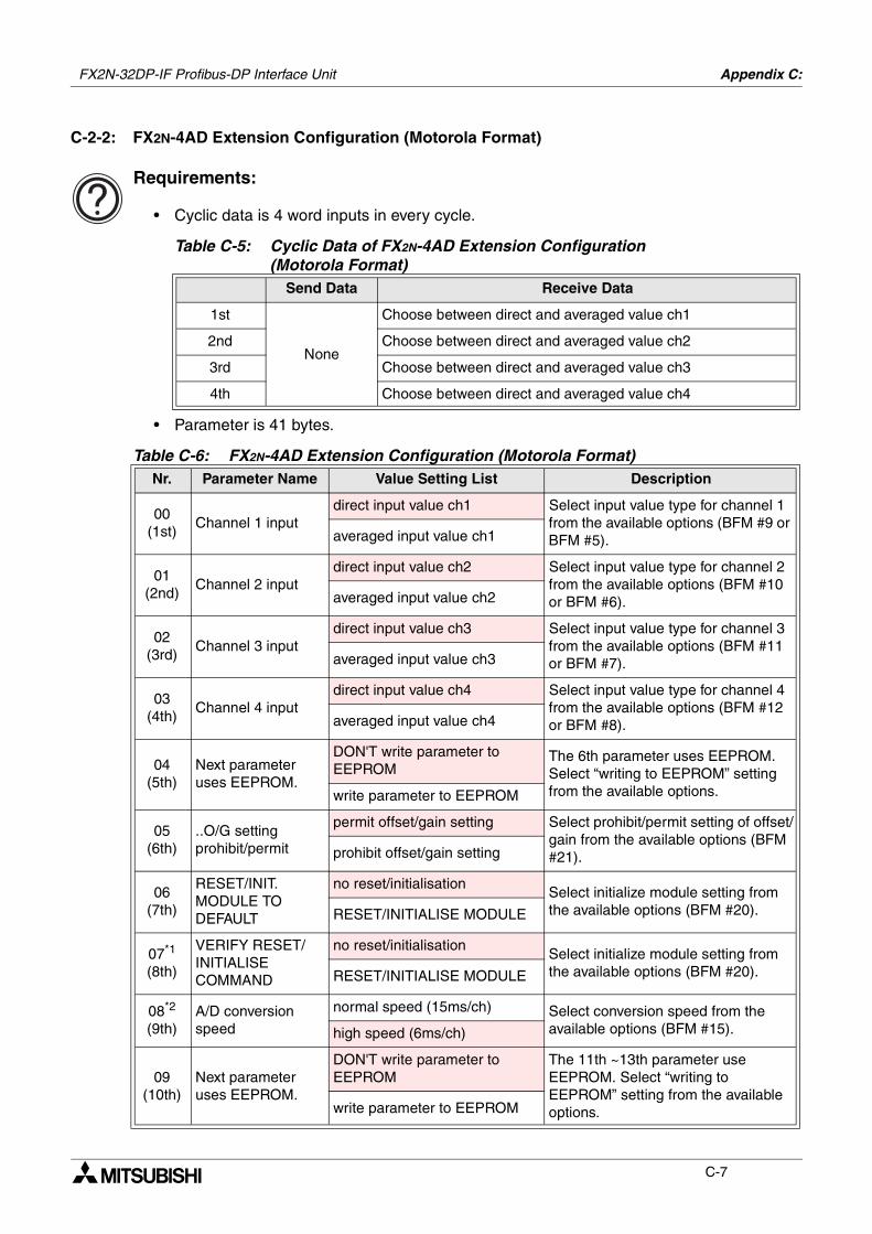
FX2N-32DP-IF Profibus-DP Interface Unit Appendix C:
C-7
C-2-2: FX2N-4AD Extension Configuration (Motorola Format)
Requirements:
• Cyclic data is 4 word inputs in every cycle.
• Parameter is 41 bytes.
Table C-5: Cyclic Data of FX2N-4AD Extension Configuration(Motorola Format)
Send Data Receive Data
1st
None
Choose between direct and averaged value ch1
2nd Choose between direct and averaged value ch2
3rd Choose between direct and averaged value ch3
4th Choose between direct and averaged value ch4
Table C-6: FX2N-4AD Extension Configuration (Motorola Format)Nr. Parameter Name Value Setting List Description
00(1st)
Channel 1 inputdirect input value ch1 Select input value type for channel 1
from the available options (BFM #9 or BFM #5).averaged input value ch1
01(2nd)
Channel 2 inputdirect input value ch2 Select input value type for channel 2
from the available options (BFM #10 or BFM #6).averaged input value ch2
02(3rd)
Channel 3 inputdirect input value ch3 Select input value type for channel 3
from the available options (BFM #11 or BFM #7).averaged input value ch3
03(4th)
Channel 4 inputdirect input value ch4 Select input value type for channel 4
from the available options (BFM #12 or BFM #8).averaged input value ch4
04(5th)
Next parameter uses EEPROM.
DON'T write parameter to EEPROM
The 6th parameter uses EEPROM. Select “writing to EEPROM” setting from the available options.write parameter to EEPROM
05(6th)
..O/G setting prohibit/permit
permit offset/gain setting Select prohibit/permit setting of offset/gain from the available options (BFM #21).prohibit offset/gain setting
06(7th)
RESET/INIT. MODULE TO DEFAULT
no reset/initialisationSelect initialize module setting from the available options (BFM #20).RESET/INITIALISE MODULE
07*1
(8th)
VERIFY RESET/INITIALISE COMMAND
no reset/initialisationSelect initialize module setting from the available options (BFM #20).RESET/INITIALISE MODULE
08*2
(9th)A/D conversion speed
normal speed (15ms/ch) Select conversion speed from the available options (BFM #15).high speed (6ms/ch)
09(10th)
Next parameter uses EEPROM.
DON'T write parameter to EEPROM
The 11th ~13th parameter use EEPROM. Select “writing to EEPROM” setting from the available options.write parameter to EEPROM
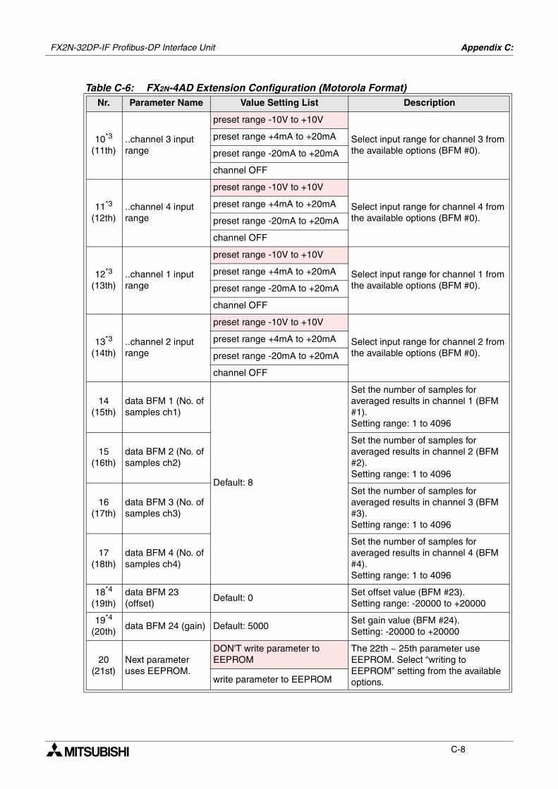
FX2N-32DP-IF Profibus-DP Interface Unit Appendix C:
C-8
10*3
(11th)..channel 3 input range
preset range -10V to +10V
Select input range for channel 3 from the available options (BFM #0).
preset range +4mA to +20mA
preset range -20mA to +20mA
channel OFF
11*3
(12th)..channel 4 input range
preset range -10V to +10V
Select input range for channel 4 from the available options (BFM #0).
preset range +4mA to +20mA
preset range -20mA to +20mA
channel OFF
12*3
(13th)..channel 1 input range
preset range -10V to +10V
Select input range for channel 1 from the available options (BFM #0).
preset range +4mA to +20mA
preset range -20mA to +20mA
channel OFF
13*3
(14th)..channel 2 input range
preset range -10V to +10V
Select input range for channel 2 from the available options (BFM #0).
preset range +4mA to +20mA
preset range -20mA to +20mA
channel OFF
14(15th)
data BFM 1 (No. of samples ch1)
Default: 8
Set the number of samples for averaged results in channel 1 (BFM #1).Setting range: 1 to 4096
15(16th)
data BFM 2 (No. of samples ch2)
Set the number of samples for averaged results in channel 2 (BFM #2).Setting range: 1 to 4096
16(17th)
data BFM 3 (No. of samples ch3)
Set the number of samples for averaged results in channel 3 (BFM #3).Setting range: 1 to 4096
17(18th)
data BFM 4 (No. of samples ch4)
Set the number of samples for averaged results in channel 4 (BFM #4).Setting range: 1 to 4096
18*4
(19th)data BFM 23 (offset)
Default: 0Set offset value (BFM #23).Setting range: -20000 to +20000
19*4
(20th)data BFM 24 (gain) Default: 5000
Set gain value (BFM #24).Setting: -20000 to +20000
20(21st)
Next parameter uses EEPROM.
DON'T write parameter to EEPROM
The 22th ~ 25th parameter use EEPROM. Select “writing to EEPROM” setting from the available options.write parameter to EEPROM
Table C-6: FX2N-4AD Extension Configuration (Motorola Format)Nr. Parameter Name Value Setting List Description
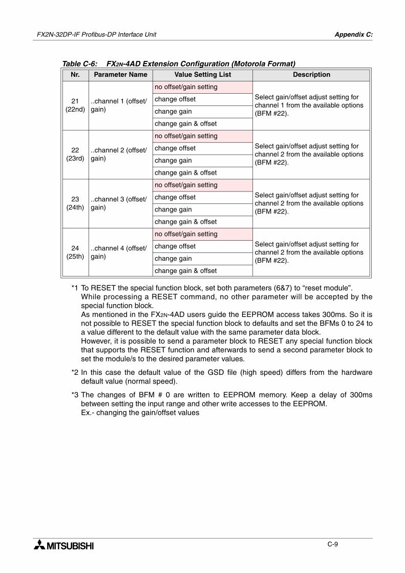
FX2N-32DP-IF Profibus-DP Interface Unit Appendix C:
C-9
*1 To RESET the special function block, set both parameters (6&7) to “reset module”.While processing a RESET command, no other parameter will be accepted by thespecial function block.As mentioned in the FX2N-4AD users guide the EEPROM access takes 300ms. So it isnot possible to RESET the special function block to defaults and set the BFMs 0 to 24 toa value different to the default value with the same parameter data block.However, it is possible to send a parameter block to RESET any special function blockthat supports the RESET function and afterwards to send a second parameter block toset the module/s to the desired parameter values.
*2 In this case the default value of the GSD file (high speed) differs from the hardwaredefault value (normal speed).
*3 The changes of BFM # 0 are written to EEPROM memory. Keep a delay of 300msbetween setting the input range and other write accesses to the EEPROM.Ex.- changing the gain/offset values
21(22nd)
..channel 1 (offset/gain)
no offset/gain setting
Select gain/offset adjust setting for channel 1 from the available options (BFM #22).
change offset
change gain
change gain & offset
22(23rd)
..channel 2 (offset/gain)
no offset/gain setting
Select gain/offset adjust setting for channel 2 from the available options (BFM #22).
change offset
change gain
change gain & offset
23(24th)
..channel 3 (offset/gain)
no offset/gain setting
Select gain/offset adjust setting for channel 2 from the available options (BFM #22).
change offset
change gain
change gain & offset
24(25th)
..channel 4 (offset/gain)
no offset/gain setting
Select gain/offset adjust setting for channel 2 from the available options (BFM #22).
change offset
change gain
change gain & offset
Table C-6: FX2N-4AD Extension Configuration (Motorola Format)Nr. Parameter Name Value Setting List Description
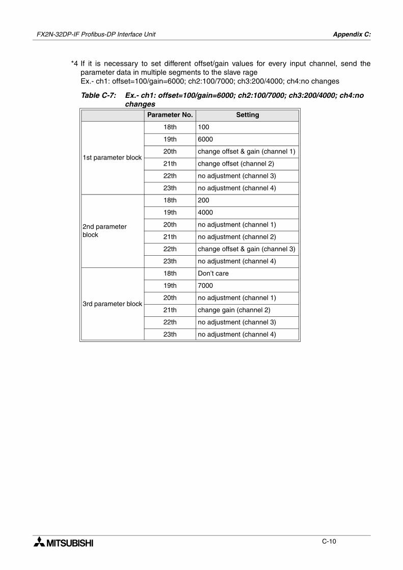
FX2N-32DP-IF Profibus-DP Interface Unit Appendix C:
C-10
*4 If it is necessary to set different offset/gain values for every input channel, send theparameter data in multiple segments to the slave rageEx.- ch1: offset=100/gain=6000; ch2:100/7000; ch3:200/4000; ch4:no changes
Table C-7: Ex.- ch1: offset=100/gain=6000; ch2:100/7000; ch3:200/4000; ch4:no changes
Parameter No. Setting
1st parameter block
18th 100
19th 6000
20th change offset & gain (channel 1)
21th change offset (channel 2)
22th no adjustment (channel 3)
23th no adjustment (channel 4)
2nd parameter block
18th 200
19th 4000
20th no adjustment (channel 1)
21th no adjustment (channel 2)
22th change offset & gain (channel 3)
23th no adjustment (channel 4)
3rd parameter block
18th Don’t care
19th 7000
20th no adjustment (channel 1)
21th change gain (channel 2)
22th no adjustment (channel 3)
23th no adjustment (channel 4)
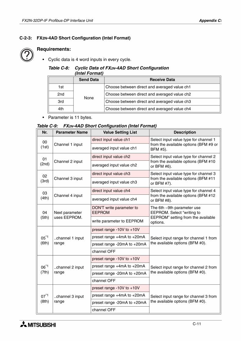
FX2N-32DP-IF Profibus-DP Interface Unit Appendix C:
C-11
C-2-3: FX2N-4AD Short Configuration (Intel Format)
Requirements:
• Cyclic data is 4 word inputs in every cycle.
• Parameter is 11 bytes.
Table C-8: Cyclic Data of FX2N-4AD Short Configuration(Intel Format)
Send Data Receive Data
1st
None
Choose between direct and averaged value ch1
2nd Choose between direct and averaged value ch2
3rd Choose between direct and averaged value ch3
4th Choose between direct and averaged value ch4
Table C-9: FX2N-4AD Short Configuration (Intel Format)Nr. Parameter Name Value Setting List Description
00(1st)
Channel 1 inputdirect input value ch1 Select input value type for channel 1
from the available options (BFM #9 or BFM #5).averaged input value ch1
01(2nd)
Channel 2 inputdirect input value ch2 Select input value type for channel 2
from the available options (BFM #10 or BFM #6).averaged input value ch2
02(3rd)
Channel 3 inputdirect input value ch3 Select input value type for channel 3
from the available options (BFM #11 or BFM #7).averaged input value ch3
03(4th)
Channel 4 inputdirect input value ch4 Select input value type for channel 4
from the available options (BFM #12 or BFM #8).averaged input value ch4
04(5th)
Next parameter uses EEPROM.
DON'T write parameter to EEPROM
The 6th ~9th parameter use EEPROM. Select “writing to EEPROM” setting from the available options.write parameter to EEPROM
05*1
(6th)..channel 1 input range
preset range -10V to +10V
Select input range for channel 1 from the available options (BFM #0).
preset range +4mA to +20mA
preset range -20mA to +20mA
channel OFF
06*1
(7th)..channel 2 input range
preset range -10V to +10V
Select input range for channel 2 from the available options (BFM #0).
preset range +4mA to +20mA
preset range -20mA to +20mA
channel OFF
07*1
(8th)..channel 3 input range
preset range -10V to +10V
Select input range for channel 3 from the available options (BFM #0).
preset range +4mA to +20mA
preset range -20mA to +20mA
channel OFF

FX2N-32DP-IF Profibus-DP Interface Unit Appendix C:
C-12
*1 The changes of BFM # 0 are written to EEPROM memory. Keep a delay of 300msbetween setting the input range and other write accesses to the EEPROM.Ex.- changing the gain/offset values
08*1
(9th)..channel 4 input range
preset range -10V to +10V
Select input range for channel 4 from the available options (BFM #0).
preset range +4mA to +20mA
preset range -20mA to +20mA
channel OFF
Table C-9: FX2N-4AD Short Configuration (Intel Format)Nr. Parameter Name Value Setting List Description

FX2N-32DP-IF Profibus-DP Interface Unit Appendix C:
C-13
C-2-4: FX2N-4AD Short Configuration (Motorola Format)
Requirements:
• Cyclic data is 4 word inputs in every cycle.
• Parameter is 11 bytes.
Table C-10: Cyclic Data of FX2N-4AD Short Configuration(Motorola Format)
Send Data Receive Data
1st
None
Choose between direct and averaged value ch1
2nd Choose between direct and averaged value ch2
3rd Choose between direct and averaged value ch3
4th Choose between direct and averaged value ch4
Table C-11: FX2N-4AD Short Configuration (Motorola Format)Nr. Parameter Name Value Setting List Description
00(1st)
Channel 1 inputdirect input value ch1 Select input value type for channel 1
from the available options (BFM #9 or BFM #5).averaged input value ch1
01(2nd)
Channel 2 inputdirect input value ch2 Select input value type for channel 2
from the available options (BFM #10 or BFM #6).averaged input value ch2
02(3rd)
Channel 3 inputdirect input value ch3 Select input value type for channel 3
from the available options (BFM #11 or BFM #7).averaged input value ch3
03(4th)
Channel 4 inputdirect input value ch4 Select input value type for channel 4
from the available options (BFM #12 or BFM #8).averaged input value ch4
04(5th)
Next parameter uses EEPROM.
DON'T write parameter to EEPROM
The 6th ~9th parameter use EEPROM. Select “writing to EEPROM” setting from the available options.write parameter to EEPROM
05*1
(6th)..channel 3 input range
preset range -10V to +10V
Select input range for channel 3 from the available options (BFM #0).
preset range +4mA to +20mA
preset range -20mA to +20mA
channel OFF
06*1
(7th)..channel 4 input range
preset range -10V to +10V
Select input range for channel 4 from the available options (BFM #0).
preset range +4mA to +20mA
preset range -20mA to +20mA
channel OFF
07*1
(8th)..channel 1 input range
preset range -10V to +10V
Select input range for channel 1 from the available options (BFM #0).
preset range +4mA to +20mA
preset range -20mA to +20mA
channel OFF

FX2N-32DP-IF Profibus-DP Interface Unit Appendix C:
C-14
*1 The changes of BFM # 0 are written to EEPROM memory. Keep a delay of 300msbetween setting the input range and other write accesses to the EEPROM.Ex.- changing the gain/offset values
08*1
(9th)..channel 2 input range
preset range -10V to +10V
Select input range for channel 2 from the available options (BFM #0).
preset range +4mA to +20mA
preset range -20mA to +20mA
channel OFF
Table C-11: FX2N-4AD Short Configuration (Motorola Format)Nr. Parameter Name Value Setting List Description
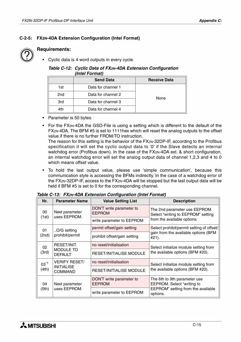
FX2N-32DP-IF Profibus-DP Interface Unit Appendix C:
C-15
C-2-5: FX2N-4DA Extension Configuration (Intel Format)
Requirements:
• Cyclic data is 4 word outputs in every cycle.
• Parameter is 50 bytes.
• For the FX2N-4DA the GSD-File is using a setting which is different to the default of theFX2N-4DA. The BFM #5 is set to 1111hex which will reset the analog outputs to the offsetvalue if there is no further FROM/TO instruction.The reason for this setting is the behavior of the FX2N-32DP-IF, according to the Profibusspecification it will set the cyclic output data to '0' if the Slave detects an internalwatchdog error (Profibus down). In the case of the FX2N-4DA ext. & short configuration,an internal watchdog error will set the analog output data of channel 1,2,3 and 4 to 0which means offset value.
• To hold the last output value, please use 'simple communication', because thiscommunication style is accessing the BFMs indirectly. In the case of a watchdog error ofthe FX2N-32DP-IF, access to the FX2N-4DA will be stopped but the last output data will beheld if BFM #5 is set to 0 for the corresponding channel.
Table C-12: Cyclic Data of FX2N-4DA Extension Configuration(Intel Format)
Send Data Receive Data
1st Data for channel 1
None2nd Data for channel 2
3rd Data for channel 3
4th Data for channel 4
Table C-13: FX2N-4DA Extension Configuration (Intel Format)Nr. Parameter Name Value Setting List Description
00(1st)
Next parameter uses EEPROM.
DON'T write parameter to EEPROM
The 2nd parameter use EEPROM. Select “writing to EEPROM” setting from the available options.write parameter to EEPROM
01(2nd)
..O/G setting prohibit/permit
permit offset/gain setting Select prohibit/permit setting of offset/gain from the available options (BFM #21).prohibit offset/gain setting
02(3rd)
RESET/INIT. MODULE TO DEFAULT
no reset/initialisationSelect initialize module setting from the available options (BFM #20).RESET/INITIALISE MODULE
03*1
(4th)
VERIFY RESET/INITIALISE COMMAND
no reset/initialisationSelect initialize module setting from the available options (BFM #20).RESET/INITIALISE MODULE
04(5th)
Next parameter uses EEPROM.
DON'T write parameter to EEPROM
The 6th to 9th parameter use EEPROM. Select “writing to EEPROM” setting from the available options.write parameter to EEPROM
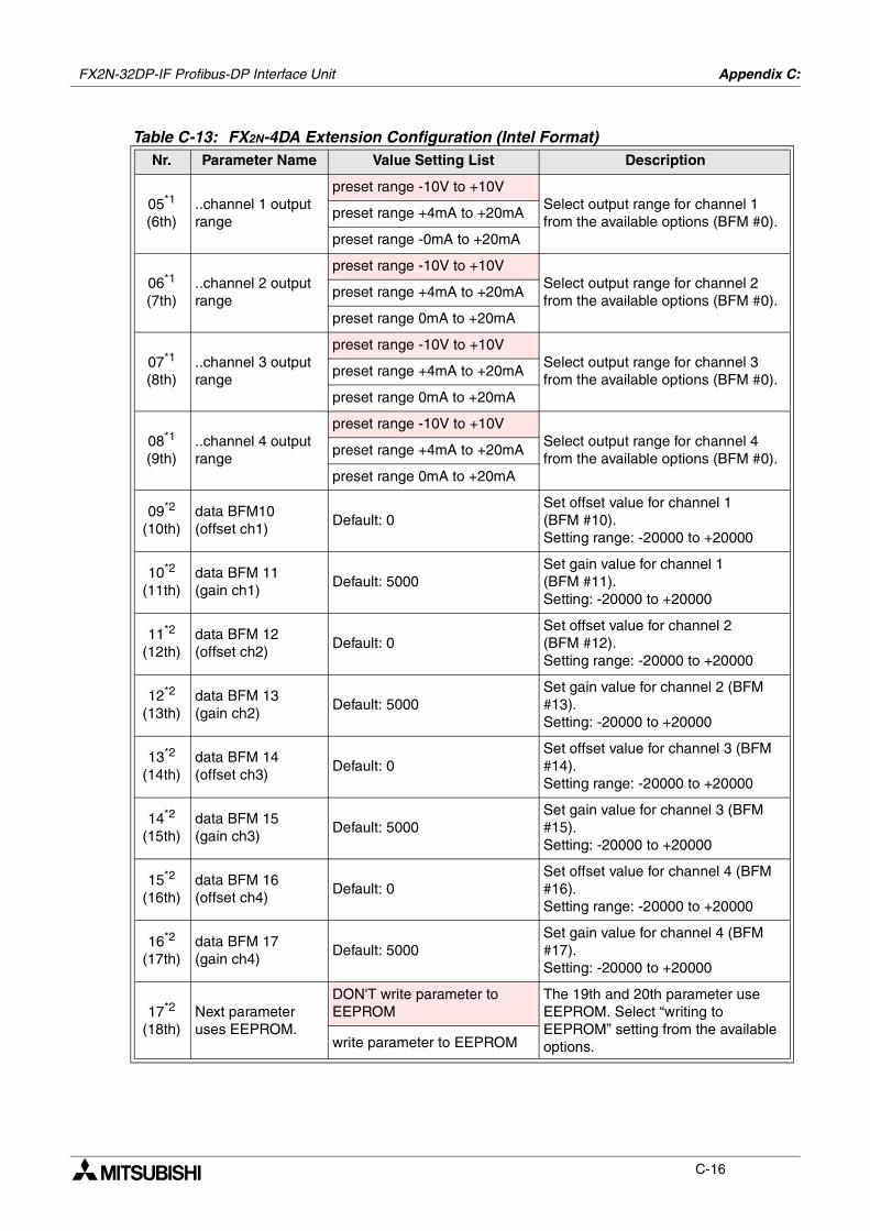
FX2N-32DP-IF Profibus-DP Interface Unit Appendix C:
C-16
05*1
(6th)..channel 1 output range
preset range -10V to +10VSelect output range for channel 1 from the available options (BFM #0).
preset range +4mA to +20mA
preset range -0mA to +20mA
06*1
(7th)..channel 2 output range
preset range -10V to +10VSelect output range for channel 2 from the available options (BFM #0).
preset range +4mA to +20mA
preset range 0mA to +20mA
07*1
(8th)..channel 3 output range
preset range -10V to +10VSelect output range for channel 3 from the available options (BFM #0).
preset range +4mA to +20mA
preset range 0mA to +20mA
08*1
(9th)..channel 4 output range
preset range -10V to +10VSelect output range for channel 4 from the available options (BFM #0).
preset range +4mA to +20mA
preset range 0mA to +20mA
09*2
(10th)data BFM10 (offset ch1)
Default: 0Set offset value for channel 1 (BFM #10).Setting range: -20000 to +20000
10*2
(11th)data BFM 11 (gain ch1)
Default: 5000Set gain value for channel 1 (BFM #11).Setting: -20000 to +20000
11*2
(12th)data BFM 12 (offset ch2)
Default: 0Set offset value for channel 2 (BFM #12).Setting range: -20000 to +20000
12*2
(13th)data BFM 13 (gain ch2)
Default: 5000Set gain value for channel 2 (BFM #13).Setting: -20000 to +20000
13*2
(14th)data BFM 14 (offset ch3)
Default: 0Set offset value for channel 3 (BFM #14).Setting range: -20000 to +20000
14*2
(15th)data BFM 15 (gain ch3)
Default: 5000Set gain value for channel 3 (BFM #15).Setting: -20000 to +20000
15*2
(16th)data BFM 16 (offset ch4)
Default: 0Set offset value for channel 4 (BFM #16).Setting range: -20000 to +20000
16*2
(17th)data BFM 17 (gain ch4)
Default: 5000Set gain value for channel 4 (BFM #17).Setting: -20000 to +20000
17*2
(18th)Next parameter uses EEPROM.
DON'T write parameter to EEPROM
The 19th and 20th parameter use EEPROM. Select “writing to EEPROM” setting from the available options.write parameter to EEPROM
Table C-13: FX2N-4DA Extension Configuration (Intel Format)Nr. Parameter Name Value Setting List Description
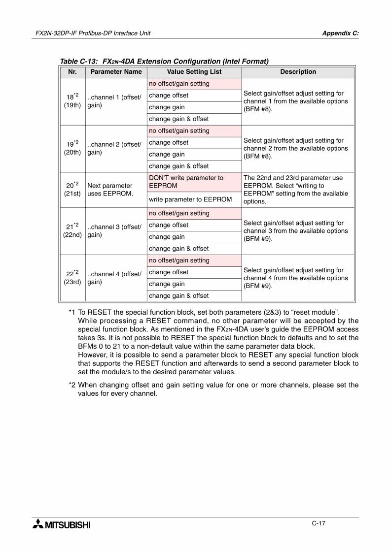
FX2N-32DP-IF Profibus-DP Interface Unit Appendix C:
C-17
*1 To RESET the special function block, set both parameters (2&3) to “reset module”.While processing a RESET command, no other parameter will be accepted by thespecial function block. As mentioned in the FX2N-4DA user’s guide the EEPROM accesstakes 3s. It is not possible to RESET the special function block to defaults and to set theBFMs 0 to 21 to a non-default value within the same parameter data block.However, it is possible to send a parameter block to RESET any special function blockthat supports the RESET function and afterwards to send a second parameter block toset the module/s to the desired parameter values.
*2 When changing offset and gain setting value for one or more channels, please set thevalues for every channel.
18*2
(19th)..channel 1 (offset/gain)
no offset/gain setting
Select gain/offset adjust setting for channel 1 from the available options (BFM #8).
change offset
change gain
change gain & offset
19*2
(20th)..channel 2 (offset/gain)
no offset/gain setting
Select gain/offset adjust setting for channel 2 from the available options (BFM #8).
change offset
change gain
change gain & offset
20*2
(21st)Next parameter uses EEPROM.
DON'T write parameter to EEPROM
The 22nd and 23rd parameter use EEPROM. Select “writing to EEPROM” setting from the available options.write parameter to EEPROM
21*2
(22nd)..channel 3 (offset/gain)
no offset/gain setting
Select gain/offset adjust setting for channel 3 from the available options (BFM #9).
change offset
change gain
change gain & offset
22*2
(23rd)..channel 4 (offset/gain)
no offset/gain setting
Select gain/offset adjust setting for channel 4 from the available options (BFM #9).
change offset
change gain
change gain & offset
Table C-13: FX2N-4DA Extension Configuration (Intel Format)Nr. Parameter Name Value Setting List Description
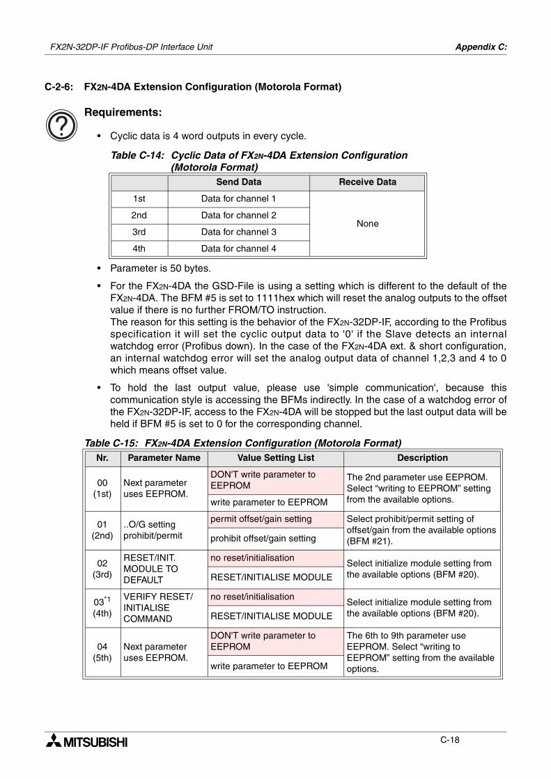
FX2N-32DP-IF Profibus-DP Interface Unit Appendix C:
C-18
C-2-6: FX2N-4DA Extension Configuration (Motorola Format)
Requirements:
• Cyclic data is 4 word outputs in every cycle.
• Parameter is 50 bytes.
• For the FX2N-4DA the GSD-File is using a setting which is different to the default of theFX2N-4DA. The BFM #5 is set to 1111hex which will reset the analog outputs to the offsetvalue if there is no further FROM/TO instruction.The reason for this setting is the behavior of the FX2N-32DP-IF, according to the Profibusspecification it will set the cyclic output data to '0' if the Slave detects an internalwatchdog error (Profibus down). In the case of the FX2N-4DA ext. & short configuration,an internal watchdog error will set the analog output data of channel 1,2,3 and 4 to 0which means offset value.
• To hold the last output value, please use 'simple communication', because thiscommunication style is accessing the BFMs indirectly. In the case of a watchdog error ofthe FX2N-32DP-IF, access to the FX2N-4DA will be stopped but the last output data will beheld if BFM #5 is set to 0 for the corresponding channel.
Table C-14: Cyclic Data of FX2N-4DA Extension Configuration(Motorola Format)
Send Data Receive Data
1st Data for channel 1
None2nd Data for channel 2
3rd Data for channel 3
4th Data for channel 4
Table C-15: FX2N-4DA Extension Configuration (Motorola Format)Nr. Parameter Name Value Setting List Description
00(1st)
Next parameter uses EEPROM.
DON'T write parameter to EEPROM
The 2nd parameter use EEPROM. Select “writing to EEPROM” setting from the available options.write parameter to EEPROM
01(2nd)
..O/G setting prohibit/permit
permit offset/gain setting Select prohibit/permit setting of offset/gain from the available options (BFM #21).prohibit offset/gain setting
02(3rd)
RESET/INIT. MODULE TO DEFAULT
no reset/initialisationSelect initialize module setting from the available options (BFM #20).RESET/INITIALISE MODULE
03*1
(4th)
VERIFY RESET/INITIALISE COMMAND
no reset/initialisationSelect initialize module setting from the available options (BFM #20).RESET/INITIALISE MODULE
04(5th)
Next parameter uses EEPROM.
DON'T write parameter to EEPROM
The 6th to 9th parameter use EEPROM. Select “writing to EEPROM” setting from the available options.write parameter to EEPROM
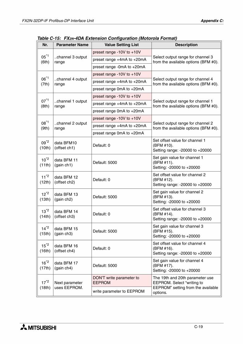
FX2N-32DP-IF Profibus-DP Interface Unit Appendix C:
C-19
05*1
(6th)..channel 3 output range
preset range -10V to +10VSelect output range for channel 3 from the available options (BFM #0).
preset range +4mA to +20mA
preset range -0mA to +20mA
06*1
(7th)..channel 4 output range
preset range -10V to +10VSelect output range for channel 4 from the available options (BFM #0).
preset range +4mA to +20mA
preset range 0mA to +20mA
07*1
(8th)..channel 1 output range
preset range -10V to +10VSelect output range for channel 1 from the available options (BFM #0).
preset range +4mA to +20mA
preset range 0mA to +20mA
08*1
(9th)..channel 2 output range
preset range -10V to +10VSelect output range for channel 2 from the available options (BFM #0).
preset range +4mA to +20mA
preset range 0mA to +20mA
09*2
(10th)data BFM10 (offset ch1)
Default: 0Set offset value for channel 1 (BFM #10).Setting range: -20000 to +20000
10*2
(11th)data BFM 11 (gain ch1)
Default: 5000Set gain value for channel 1 (BFM #11).Setting: -20000 to +20000
11*2
(12th)data BFM 12 (offset ch2)
Default: 0Set offset value for channel 2 (BFM #12).Setting range: -20000 to +20000
12*2
(13th)data BFM 13 (gain ch2)
Default: 5000Set gain value for channel 2 (BFM #13).Setting: -20000 to +20000
13*2
(14th)data BFM 14 (offset ch3)
Default: 0Set offset value for channel 3 (BFM #14).Setting range: -20000 to +20000
14*2
(15th)data BFM 15 (gain ch3)
Default: 5000Set gain value for channel 3 (BFM #15).Setting: -20000 to +20000
15*2
(16th)data BFM 16 (offset ch4)
Default: 0Set offset value for channel 4 (BFM #16).Setting range: -20000 to +20000
16*2
(17th)data BFM 17 (gain ch4)
Default: 5000Set gain value for channel 4 (BFM #17).Setting: -20000 to +20000
17*2
(18th)Next parameter uses EEPROM.
DON'T write parameter to EEPROM
The 19th and 20th parameter use EEPROM. Select “writing to EEPROM” setting from the available options.write parameter to EEPROM
Table C-15: FX2N-4DA Extension Configuration (Motorola Format)Nr. Parameter Name Value Setting List Description
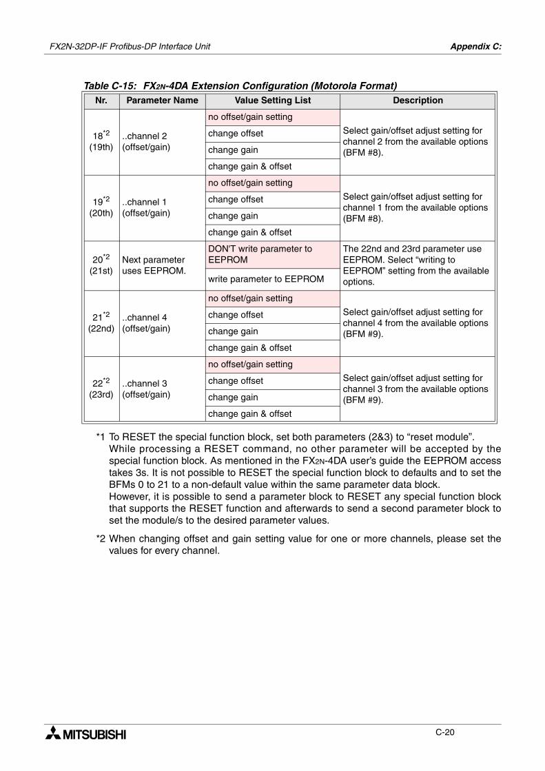
FX2N-32DP-IF Profibus-DP Interface Unit Appendix C:
C-20
*1 To RESET the special function block, set both parameters (2&3) to “reset module”.While processing a RESET command, no other parameter will be accepted by thespecial function block. As mentioned in the FX2N-4DA user’s guide the EEPROM accesstakes 3s. It is not possible to RESET the special function block to defaults and to set theBFMs 0 to 21 to a non-default value within the same parameter data block.However, it is possible to send a parameter block to RESET any special function blockthat supports the RESET function and afterwards to send a second parameter block toset the module/s to the desired parameter values.
*2 When changing offset and gain setting value for one or more channels, please set thevalues for every channel.
18*2
(19th)..channel 2 (offset/gain)
no offset/gain setting
Select gain/offset adjust setting for channel 2 from the available options (BFM #8).
change offset
change gain
change gain & offset
19*2
(20th)..channel 1 (offset/gain)
no offset/gain setting
Select gain/offset adjust setting for channel 1 from the available options (BFM #8).
change offset
change gain
change gain & offset
20*2
(21st)Next parameter uses EEPROM.
DON'T write parameter to EEPROM
The 22nd and 23rd parameter use EEPROM. Select “writing to EEPROM” setting from the available options.write parameter to EEPROM
21*2
(22nd)..channel 4 (offset/gain)
no offset/gain setting
Select gain/offset adjust setting for channel 4 from the available options (BFM #9).
change offset
change gain
change gain & offset
22*2
(23rd)..channel 3 (offset/gain)
no offset/gain setting
Select gain/offset adjust setting for channel 3 from the available options (BFM #9).
change offset
change gain
change gain & offset
Table C-15: FX2N-4DA Extension Configuration (Motorola Format)Nr. Parameter Name Value Setting List Description
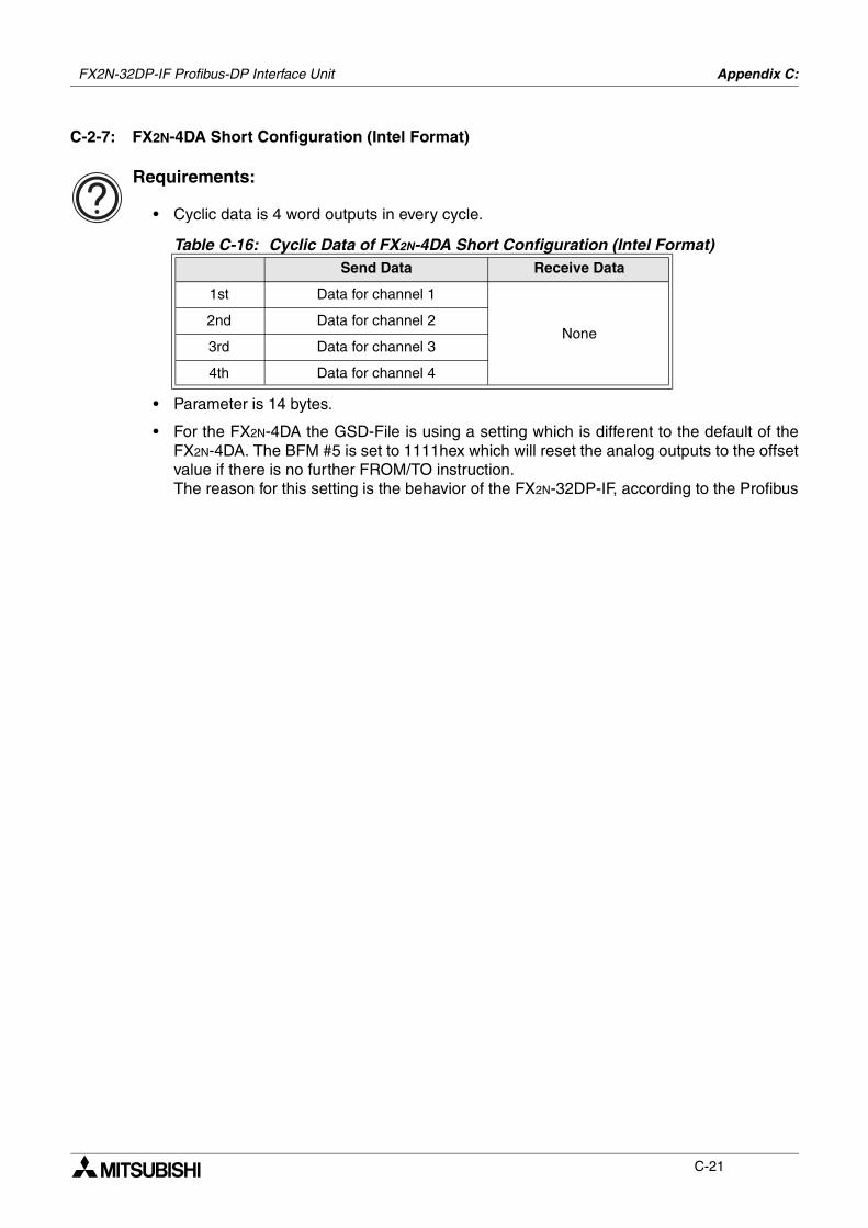
FX2N-32DP-IF Profibus-DP Interface Unit Appendix C:
C-21
C-2-7: FX2N-4DA Short Configuration (Intel Format)
Requirements:
• Cyclic data is 4 word outputs in every cycle.
• Parameter is 14 bytes.
• For the FX2N-4DA the GSD-File is using a setting which is different to the default of theFX2N-4DA. The BFM #5 is set to 1111hex which will reset the analog outputs to the offsetvalue if there is no further FROM/TO instruction.The reason for this setting is the behavior of the FX2N-32DP-IF, according to the Profibus
Table C-16: Cyclic Data of FX2N-4DA Short Configuration (Intel Format)Send Data Receive Data
1st Data for channel 1
None2nd Data for channel 2
3rd Data for channel 3
4th Data for channel 4
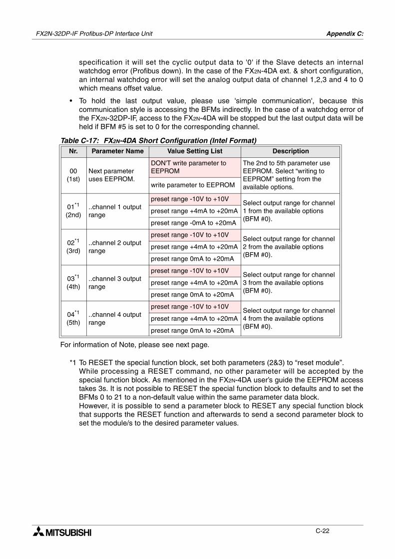
FX2N-32DP-IF Profibus-DP Interface Unit Appendix C:
C-22
specification it will set the cyclic output data to '0' if the Slave detects an internalwatchdog error (Profibus down). In the case of the FX2N-4DA ext. & short configuration,an internal watchdog error will set the analog output data of channel 1,2,3 and 4 to 0which means offset value.
• To hold the last output value, please use 'simple communication', because thiscommunication style is accessing the BFMs indirectly. In the case of a watchdog error ofthe FX2N-32DP-IF, access to the FX2N-4DA will be stopped but the last output data will beheld if BFM #5 is set to 0 for the corresponding channel.
For information of Note, please see next page.
*1 To RESET the special function block, set both parameters (2&3) to “reset module”.While processing a RESET command, no other parameter will be accepted by thespecial function block. As mentioned in the FX2N-4DA user’s guide the EEPROM accesstakes 3s. It is not possible to RESET the special function block to defaults and to set theBFMs 0 to 21 to a non-default value within the same parameter data block.However, it is possible to send a parameter block to RESET any special function blockthat supports the RESET function and afterwards to send a second parameter block toset the module/s to the desired parameter values.
Table C-17: FX2N-4DA Short Configuration (Intel Format)Nr. Parameter Name Value Setting List Description
00(1st)
Next parameter uses EEPROM.
DON'T write parameter to EEPROM
The 2nd to 5th parameter use EEPROM. Select “writing to EEPROM” setting from the available options.write parameter to EEPROM
01*1
(2nd)..channel 1 output range
preset range -10V to +10VSelect output range for channel 1 from the available options (BFM #0).
preset range +4mA to +20mA
preset range -0mA to +20mA
02*1
(3rd)..channel 2 output range
preset range -10V to +10VSelect output range for channel 2 from the available options (BFM #0).
preset range +4mA to +20mA
preset range 0mA to +20mA
03*1
(4th)..channel 3 output range
preset range -10V to +10VSelect output range for channel 3 from the available options (BFM #0).
preset range +4mA to +20mA
preset range 0mA to +20mA
04*1
(5th)..channel 4 output range
preset range -10V to +10VSelect output range for channel 4 from the available options (BFM #0).
preset range +4mA to +20mA
preset range 0mA to +20mA
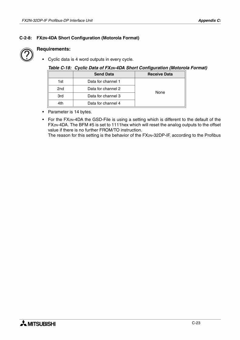
FX2N-32DP-IF Profibus-DP Interface Unit Appendix C:
C-23
C-2-8: FX2N-4DA Short Configuration (Motorola Format)
Requirements:
• Cyclic data is 4 word outputs in every cycle.
• Parameter is 14 bytes.
• For the FX2N-4DA the GSD-File is using a setting which is different to the default of theFX2N-4DA. The BFM #5 is set to 1111hex which will reset the analog outputs to the offsetvalue if there is no further FROM/TO instruction.The reason for this setting is the behavior of the FX2N-32DP-IF, according to the Profibus
Table C-18: Cyclic Data of FX2N-4DA Short Configuration (Motorola Format)Send Data Receive Data
1st Data for channel 1
None2nd Data for channel 2
3rd Data for channel 3
4th Data for channel 4
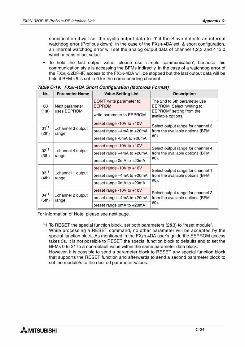
FX2N-32DP-IF Profibus-DP Interface Unit Appendix C:
C-24
specification it will set the cyclic output data to '0' if the Slave detects an internalwatchdog error (Profibus down). In the case of the FX2N-4DA ext. & short configuration,an internal watchdog error will set the analog output data of channel 1,2,3 and 4 to 0which means offset value.
• To hold the last output value, please use 'simple communication', because thiscommunication style is accessing the BFMs indirectly. In the case of a watchdog error ofthe FX2N-32DP-IF, access to the FX2N-4DA will be stopped but the last output data will beheld if BFM #5 is set to 0 for the corresponding channel.
For information of Note, please see next page.
*1 To RESET the special function block, set both parameters (2&3) to “reset module”.While processing a RESET command, no other parameter will be accepted by thespecial function block. As mentioned in the FX2N-4DA user’s guide the EEPROM accesstakes 3s. It is not possible to RESET the special function block to defaults and to set theBFMs 0 to 21 to a non-default value within the same parameter data block.However, it is possible to send a parameter block to RESET any special function blockthat supports the RESET function and afterwards to send a second parameter block toset the module/s to the desired parameter values.
Table C-19: FX2N-4DA Short Configuration (Motorola Format)Nr. Parameter Name Value Setting List Description
00(1st)
Next parameter uses EEPROM.
DON'T write parameter to EEPROM
The 2nd to 5th parameter use EEPROM. Select “writing to EEPROM” setting from the available options.write parameter to EEPROM
01*1
(2th)..channel 3 output range
preset range -10V to +10VSelect output range for channel 3 from the available options (BFM #0).
preset range +4mA to +20mA
preset range -0mA to +20mA
02*1
(3th)..channel 4 output range
preset range -10V to +10VSelect output range for channel 4 from the available options (BFM #0).
preset range +4mA to +20mA
preset range 0mA to +20mA
03*1
(4th)..channel 1 output range
preset range -10V to +10VSelect output range for channel 1 from the available options (BFM #0).
preset range +4mA to +20mA
preset range 0mA to +20mA
04*1
(5th)..channel 2 output range
preset range -10V to +10VSelect output range for channel 2 from the available options (BFM #0).
preset range +4mA to +20mA
preset range 0mA to +20mA
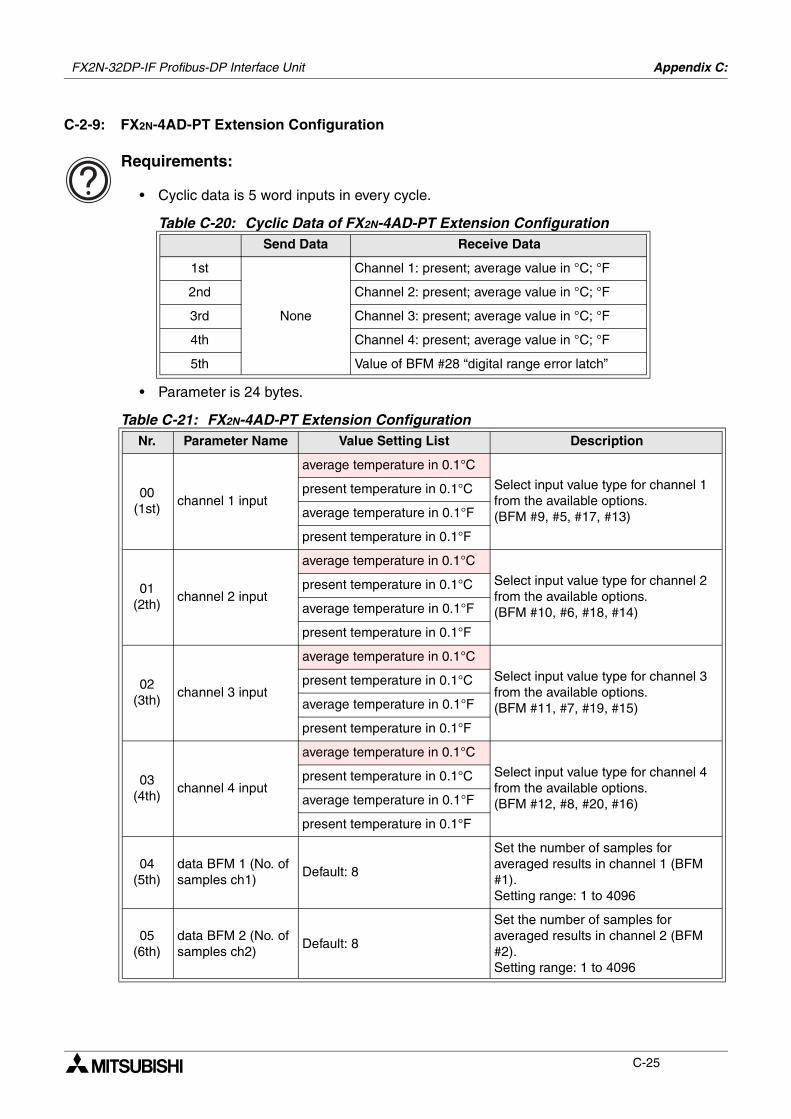
FX2N-32DP-IF Profibus-DP Interface Unit Appendix C:
C-25
C-2-9: FX2N-4AD-PT Extension Configuration
Requirements:
• Cyclic data is 5 word inputs in every cycle.
• Parameter is 24 bytes.
Table C-20: Cyclic Data of FX2N-4AD-PT Extension ConfigurationSend Data Receive Data
1st
None
Channel 1: present; average value in °C; °F
2nd Channel 2: present; average value in °C; °F
3rd Channel 3: present; average value in °C; °F
4th Channel 4: present; average value in °C; °F
5th Value of BFM #28 “digital range error latch”
Table C-21: FX2N-4AD-PT Extension ConfigurationNr. Parameter Name Value Setting List Description
00(1st)
channel 1 input
average temperature in 0.1°C
Select input value type for channel 1 from the available options. (BFM #9, #5, #17, #13)
present temperature in 0.1°C
average temperature in 0.1°F
present temperature in 0.1°F
01(2th)
channel 2 input
average temperature in 0.1°C
Select input value type for channel 2 from the available options. (BFM #10, #6, #18, #14)
present temperature in 0.1°C
average temperature in 0.1°F
present temperature in 0.1°F
02(3th)
channel 3 input
average temperature in 0.1°C
Select input value type for channel 3 from the available options. (BFM #11, #7, #19, #15)
present temperature in 0.1°C
average temperature in 0.1°F
present temperature in 0.1°F
03(4th)
channel 4 input
average temperature in 0.1°C
Select input value type for channel 4 from the available options. (BFM #12, #8, #20, #16)
present temperature in 0.1°C
average temperature in 0.1°F
present temperature in 0.1°F
04(5th)
data BFM 1 (No. of samples ch1)
Default: 8
Set the number of samples for averaged results in channel 1 (BFM #1).Setting range: 1 to 4096
05(6th)
data BFM 2 (No. of samples ch2)
Default: 8
Set the number of samples for averaged results in channel 2 (BFM #2).Setting range: 1 to 4096
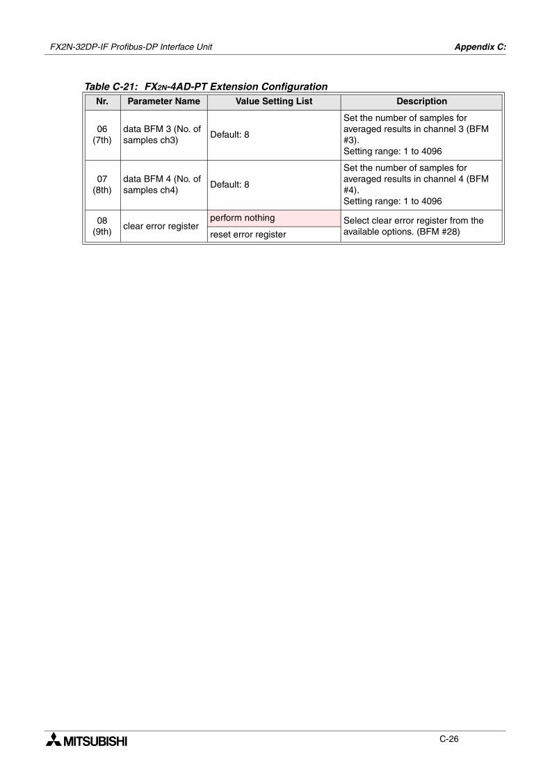
FX2N-32DP-IF Profibus-DP Interface Unit Appendix C:
C-26
06(7th)
data BFM 3 (No. of samples ch3)
Default: 8
Set the number of samples for averaged results in channel 3 (BFM #3).Setting range: 1 to 4096
07(8th)
data BFM 4 (No. of samples ch4)
Default: 8
Set the number of samples for averaged results in channel 4 (BFM #4).Setting range: 1 to 4096
08(9th)
clear error registerperform nothing Select clear error register from the
available options. (BFM #28)reset error register
Table C-21: FX2N-4AD-PT Extension ConfigurationNr. Parameter Name Value Setting List Description
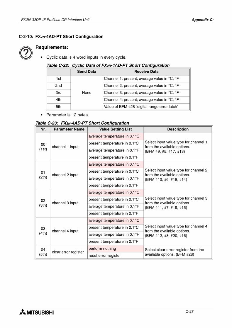
FX2N-32DP-IF Profibus-DP Interface Unit Appendix C:
C-27
C-2-10: FX2N-4AD-PT Short Configuration
Requirements:
• Cyclic data is 4 word inputs in every cycle.
• Parameter is 12 bytes.
Table C-22: Cyclic Data of FX2N-4AD-PT Short ConfigurationSend Data Receive Data
1st
None
Channel 1: present; average value in °C; °F
2nd Channel 2: present; average value in °C; °F
3rd Channel 3: present; average value in °C; °F
4th Channel 4: present; average value in °C; °F
5th Value of BFM #28 “digital range error latch”
Table C-23: FX2N-4AD-PT Short ConfigurationNr. Parameter Name Value Setting List Description
00(1st)
channel 1 input
average temperature in 0.1°C
Select input value type for channel 1 from the available options. (BFM #9, #5, #17, #13)
present temperature in 0.1°C
average temperature in 0.1°F
present temperature in 0.1°F
01(2th)
channel 2 input
average temperature in 0.1°C
Select input value type for channel 2 from the available options. (BFM #10, #6, #18, #14)
present temperature in 0.1°C
average temperature in 0.1°F
present temperature in 0.1°F
02(3th)
channel 3 input
average temperature in 0.1°C
Select input value type for channel 3 from the available options. (BFM #11, #7, #19, #15)
present temperature in 0.1°C
average temperature in 0.1°F
present temperature in 0.1°F
03(4th)
channel 4 input
average temperature in 0.1°C
Select input value type for channel 4 from the available options. (BFM #12, #8, #20, #16)
present temperature in 0.1°C
average temperature in 0.1°F
present temperature in 0.1°F
04(5th)
clear error registerperform nothing Select clear error register from the
available options. (BFM #28)reset error register
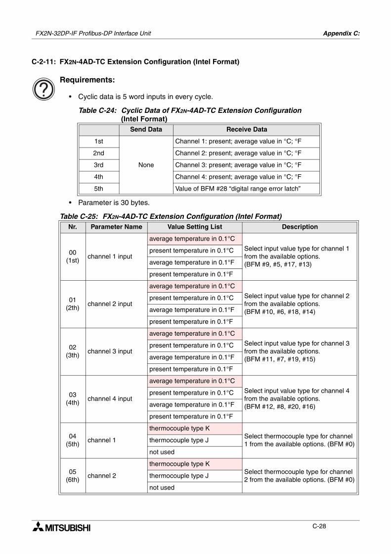
FX2N-32DP-IF Profibus-DP Interface Unit Appendix C:
C-28
C-2-11: FX2N-4AD-TC Extension Configuration (Intel Format)
Requirements:
• Cyclic data is 5 word inputs in every cycle.
• Parameter is 30 bytes.
Table C-24: Cyclic Data of FX2N-4AD-TC Extension Configuration (Intel Format)
Send Data Receive Data
1st
None
Channel 1: present; average value in °C; °F
2nd Channel 2: present; average value in °C; °F
3rd Channel 3: present; average value in °C; °F
4th Channel 4: present; average value in °C; °F
5th Value of BFM #28 “digital range error latch”
Table C-25: FX2N-4AD-TC Extension Configuration (Intel Format)Nr. Parameter Name Value Setting List Description
00(1st)
channel 1 input
average temperature in 0.1°C
Select input value type for channel 1 from the available options. (BFM #9, #5, #17, #13)
present temperature in 0.1°C
average temperature in 0.1°F
present temperature in 0.1°F
01(2th)
channel 2 input
average temperature in 0.1°C
Select input value type for channel 2 from the available options. (BFM #10, #6, #18, #14)
present temperature in 0.1°C
average temperature in 0.1°F
present temperature in 0.1°F
02(3th)
channel 3 input
average temperature in 0.1°C
Select input value type for channel 3 from the available options. (BFM #11, #7, #19, #15)
present temperature in 0.1°C
average temperature in 0.1°F
present temperature in 0.1°F
03(4th)
channel 4 input
average temperature in 0.1°C
Select input value type for channel 4 from the available options. (BFM #12, #8, #20, #16)
present temperature in 0.1°C
average temperature in 0.1°F
present temperature in 0.1°F
04(5th)
channel 1
thermocouple type KSelect thermocouple type for channel 1 from the available options. (BFM #0)
thermocouple type J
not used
05(6th)
channel 2
thermocouple type KSelect thermocouple type for channel 2 from the available options. (BFM #0)
thermocouple type J
not used

FX2N-32DP-IF Profibus-DP Interface Unit Appendix C:
C-29
06(7th)
channel 3
thermocouple type KSelect thermocouple type for channel 3 from the available options. (BFM #0)
thermocouple type J
not used
07(8th)
channel 4
thermocouple type KSelect thermocouple type for channel 4 from the available options. (BFM #0)
thermocouple type J
not used
08(9th)
clear error registerperform nothing Select clear error register from the
available options. (BFM #28)reset error register
09(10th)
data BFM 1 (No. of samples ch1)
Default: 8
Set the number of samples for averaged results in channel 1 (BFM #1).Setting range: 1 to 256
10(11th)
data BFM 2 (No. of samples ch2)
Default: 8
Set the number of samples for averaged results in channel 2 (BFM #2).Setting range: 1 to 256
11(12th)
data BFM 3 (No. of samples ch3)
Default: 8
Set the number of samples for averaged results in channel 3 (BFM #3).Setting range: 1 to 256
12(13th)
data BFM 4 (No. of samples ch4)
Default: 8
Set the number of samples for averaged results in channel 4 (BFM #4).Setting range: 1 to 256
Table C-25: FX2N-4AD-TC Extension Configuration (Intel Format)Nr. Parameter Name Value Setting List Description
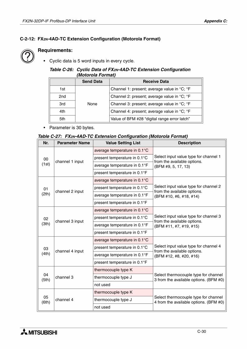
FX2N-32DP-IF Profibus-DP Interface Unit Appendix C:
C-30
C-2-12: FX2N-4AD-TC Extension Configuration (Motorola Format)
Requirements:
• Cyclic data is 5 word inputs in every cycle.
• Parameter is 30 bytes.
Table C-26: Cyclic Data of FX2N-4AD-TC Extension Configuration (Motorola Format)
Send Data Receive Data
1st
None
Channel 1: present; average value in °C; °F
2nd Channel 2: present; average value in °C; °F
3rd Channel 3: present; average value in °C; °F
4th Channel 4: present; average value in °C; °F
5th Value of BFM #28 “digital range error latch”
Table C-27: FX2N-4AD-TC Extension Configuration (Motorola Format)Nr. Parameter Name Value Setting List Description
00(1st)
channel 1 input
average temperature in 0.1°C
Select input value type for channel 1 from the available options. (BFM #9, 5, 17, 13)
present temperature in 0.1°C
average temperature in 0.1°F
present temperature in 0.1°F
01(2th)
channel 2 input
average temperature in 0.1°C
Select input value type for channel 2 from the available options. (BFM #10, #6, #18, #14)
present temperature in 0.1°C
average temperature in 0.1°F
present temperature in 0.1°F
02(3th)
channel 3 input
average temperature in 0.1°C
Select input value type for channel 3 from the available options. (BFM #11, #7, #19, #15)
present temperature in 0.1°C
average temperature in 0.1°F
present temperature in 0.1°F
03(4th)
channel 4 input
average temperature in 0.1°C
Select input value type for channel 4 from the available options. (BFM #12, #8, #20, #16)
present temperature in 0.1°C
average temperature in 0.1°F
present temperature in 0.1°F
04(5th)
channel 3
thermocouple type KSelect thermocouple type for channel 3 from the available options. (BFM #0)
thermocouple type J
not used
05(6th)
channel 4
thermocouple type KSelect thermocouple type for channel 4 from the available options. (BFM #0)
thermocouple type J
not used
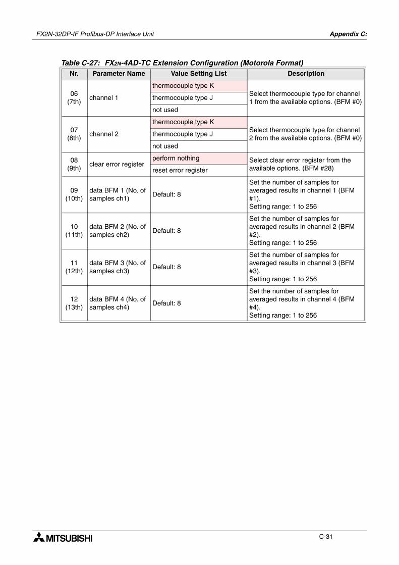
FX2N-32DP-IF Profibus-DP Interface Unit Appendix C:
C-31
06(7th)
channel 1
thermocouple type KSelect thermocouple type for channel 1 from the available options. (BFM #0)
thermocouple type J
not used
07(8th)
channel 2
thermocouple type KSelect thermocouple type for channel 2 from the available options. (BFM #0)
thermocouple type J
not used
08(9th)
clear error registerperform nothing Select clear error register from the
available options. (BFM #28)reset error register
09(10th)
data BFM 1 (No. of samples ch1)
Default: 8
Set the number of samples for averaged results in channel 1 (BFM #1).Setting range: 1 to 256
10(11th)
data BFM 2 (No. of samples ch2)
Default: 8
Set the number of samples for averaged results in channel 2 (BFM #2).Setting range: 1 to 256
11(12th)
data BFM 3 (No. of samples ch3)
Default: 8
Set the number of samples for averaged results in channel 3 (BFM #3).Setting range: 1 to 256
12(13th)
data BFM 4 (No. of samples ch4)
Default: 8
Set the number of samples for averaged results in channel 4 (BFM #4).Setting range: 1 to 256
Table C-27: FX2N-4AD-TC Extension Configuration (Motorola Format)Nr. Parameter Name Value Setting List Description
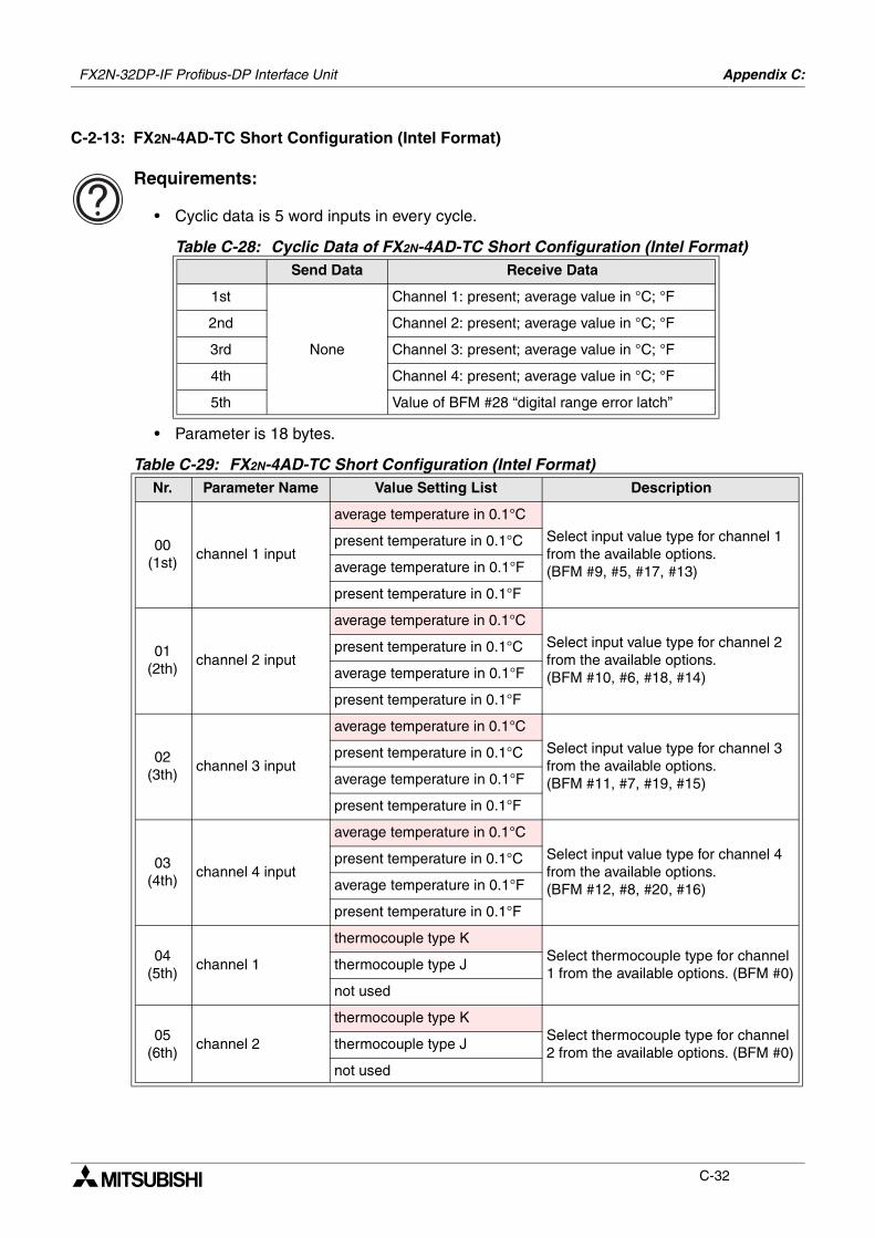
FX2N-32DP-IF Profibus-DP Interface Unit Appendix C:
C-32
C-2-13: FX2N-4AD-TC Short Configuration (Intel Format)
Requirements:
• Cyclic data is 5 word inputs in every cycle.
• Parameter is 18 bytes.
Table C-28: Cyclic Data of FX2N-4AD-TC Short Configuration (Intel Format)Send Data Receive Data
1st
None
Channel 1: present; average value in °C; °F
2nd Channel 2: present; average value in °C; °F
3rd Channel 3: present; average value in °C; °F
4th Channel 4: present; average value in °C; °F
5th Value of BFM #28 “digital range error latch”
Table C-29: FX2N-4AD-TC Short Configuration (Intel Format)Nr. Parameter Name Value Setting List Description
00(1st)
channel 1 input
average temperature in 0.1°C
Select input value type for channel 1 from the available options. (BFM #9, #5, #17, #13)
present temperature in 0.1°C
average temperature in 0.1°F
present temperature in 0.1°F
01(2th)
channel 2 input
average temperature in 0.1°C
Select input value type for channel 2 from the available options. (BFM #10, #6, #18, #14)
present temperature in 0.1°C
average temperature in 0.1°F
present temperature in 0.1°F
02(3th)
channel 3 input
average temperature in 0.1°C
Select input value type for channel 3 from the available options. (BFM #11, #7, #19, #15)
present temperature in 0.1°C
average temperature in 0.1°F
present temperature in 0.1°F
03(4th)
channel 4 input
average temperature in 0.1°C
Select input value type for channel 4 from the available options. (BFM #12, #8, #20, #16)
present temperature in 0.1°C
average temperature in 0.1°F
present temperature in 0.1°F
04(5th)
channel 1
thermocouple type KSelect thermocouple type for channel 1 from the available options. (BFM #0)
thermocouple type J
not used
05(6th)
channel 2
thermocouple type KSelect thermocouple type for channel 2 from the available options. (BFM #0)
thermocouple type J
not used
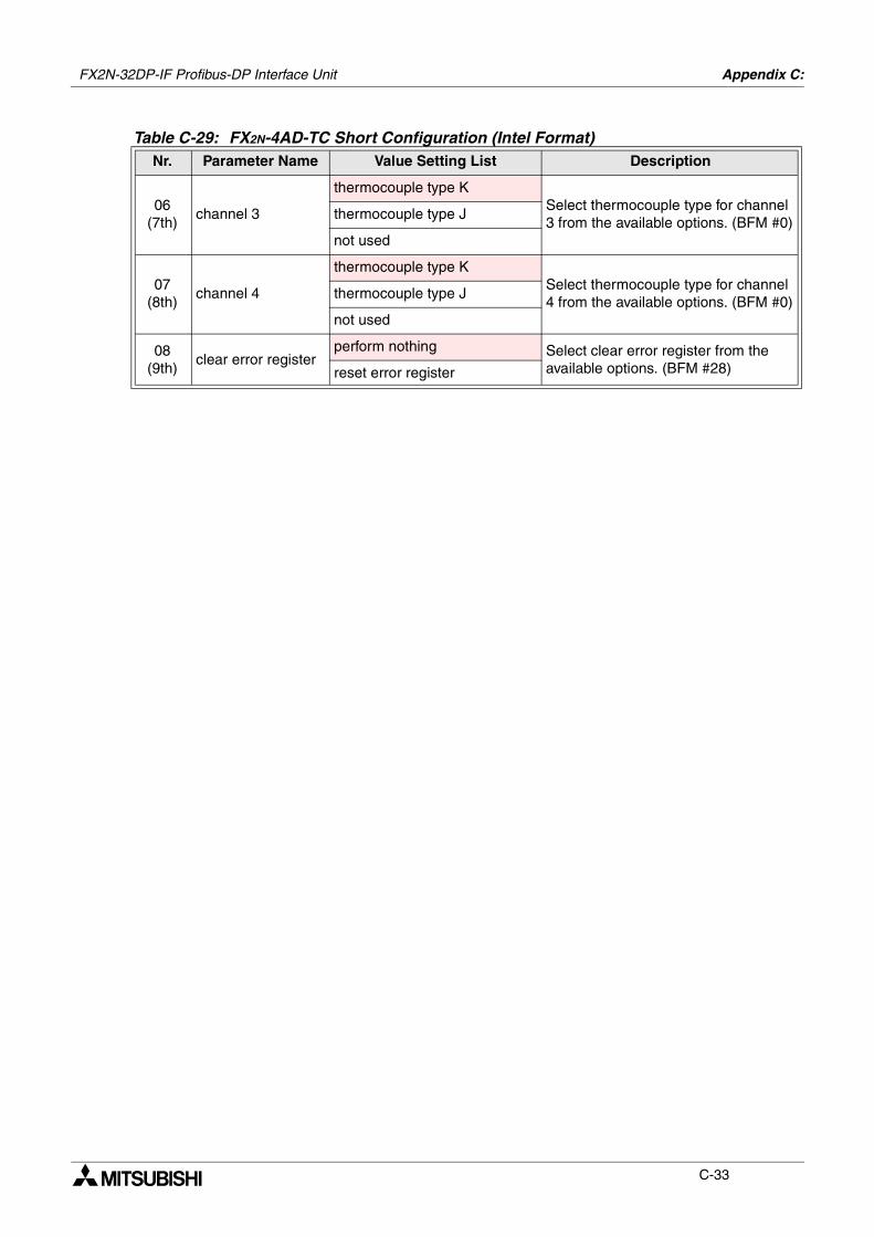
FX2N-32DP-IF Profibus-DP Interface Unit Appendix C:
C-33
06(7th)
channel 3
thermocouple type KSelect thermocouple type for channel 3 from the available options. (BFM #0)
thermocouple type J
not used
07(8th)
channel 4
thermocouple type KSelect thermocouple type for channel 4 from the available options. (BFM #0)
thermocouple type J
not used
08(9th)
clear error registerperform nothing Select clear error register from the
available options. (BFM #28)reset error register
Table C-29: FX2N-4AD-TC Short Configuration (Intel Format)Nr. Parameter Name Value Setting List Description

FX2N-32DP-IF Profibus-DP Interface Unit Appendix C:
C-34
C-2-14: FX2N-4AD-TC Short Configuration (Motorola Format)
Requirements:
• Cyclic data is 5 word inputs in every cycle.
• Parameter is 18 bytes.
Table C-30: Cyclic Data of FX2N-4AD-TC Short Configuration (Motorola Format)Send Data Receive Data
1st
None
Channel 1: present; average value in °C; °F
2nd Channel 2: present; average value in °C; °F
3rd Channel 3: present; average value in °C; °F
4th Channel 4: present; average value in °C; °F
5th Value of BFM #28 “digital range error latch”
Table C-31: FX2N-4AD-TC Short Configuration (Motorola Format)Nr. Parameter Name Value Setting List Description
00(1st)
channel 1 input
average temperature in 0.1°C
Select input value type for channel 1 from the available options. (BFM #9, #5, #17, #13)
present temperature in 0.1°C
average temperature in 0.1°F
present temperature in 0.1°F
01(2th)
channel 2 input
average temperature in 0.1°C
Select input value type for channel 2 from the available options. (BFM #10, #6, #18, #14)
present temperature in 0.1°C
average temperature in 0.1°F
present temperature in 0.1°F
02(3th)
channel 3 input
average temperature in 0.1°C
Select input value type for channel 3 from the available options. (BFM #11, #7, #19, #15)
present temperature in 0.1°C
average temperature in 0.1°F
present temperature in 0.1°F
03(4th)
channel 4 input
average temperature in 0.1°C
Select input value type for channel 4 from the available options. (BFM #12, #8, #20, #16)
present temperature in 0.1°C
average temperature in 0.1°F
present temperature in 0.1°F
04(5th)
channel 3
thermocouple type KSelect thermocouple type for channel 3 from the available options. (BFM #0)
thermocouple type J
not used
05(6th)
channel 4
thermocouple type KSelect thermocouple type for channel 4 from the available options. (BFM #0)
thermocouple type J
not used
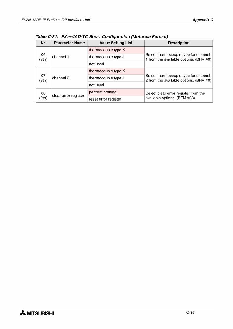
FX2N-32DP-IF Profibus-DP Interface Unit Appendix C:
C-35
06(7th)
channel 1
thermocouple type KSelect thermocouple type for channel 1 from the available options. (BFM #0)
thermocouple type J
not used
07(8th)
channel 2
thermocouple type KSelect thermocouple type for channel 2 from the available options. (BFM #0)
thermocouple type J
not used
08(9th)
clear error registerperform nothing Select clear error register from the
available options. (BFM #28)reset error register
Table C-31: FX2N-4AD-TC Short Configuration (Motorola Format)Nr. Parameter Name Value Setting List Description
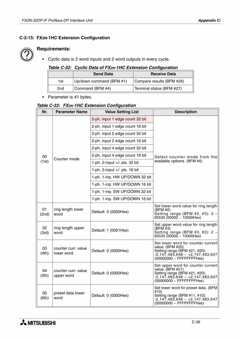
FX2N-32DP-IF Profibus-DP Interface Unit Appendix C:
C-36
C-2-15: FX2N-1HC Extension Configuration
Requirements:
• Cyclic data is 2 word inputs and 2 word outputs in every cycle.
• Parameter is 41 bytes.
Table C-32: Cyclic Data of FX2N-1HC Extension ConfigurationSend Data Receive Data
1st Up/down command (BFM #1) Compare results (BFM #26)
2nd Command (BFM #4) Terminal status (BFM #27)
Table C-33: FX2N-1HC Extension ConfigurationNr. Parameter Name Value Setting List Description
00(1st)
Counter mode
2-ph. input 1 edge count 32 bit
Select counter mode from theavailable options. (BFM #0)
2-ph. input 1 edge count 16 bit
2-ph. input 2 edge count 32 bit
2-ph. input 2 edge count 16 bit
2-ph. input 4 edge count 32 bit
2-ph. input 4 edge count 16 bit
1-ph. 2-input +/- pls. 32 bit
1-ph. 2-input +/- pls. 16 bit
1-ph. 1-inp. HW UP/DOWN 32 bit
1-ph. 1-inp. HW UP/DOWN 16 bit
1-ph. 1-inp. SW UP/DOWN 32 bit
1-ph. 1-inp. SW UP/DOWN 16 bit
01(2nd)
ring length lower word
Default: 0 (0000Hex)
Set lower word value for ring length(BFM #2)Setting range (BFM #2, #3): 2 ~65535 (00002 ~ 10000Hex)
02(3rd)
ring length upper word
Default: 1 (0001Hex)Set upper word value for ring length(BFM #3)Setting range (BFM #3, #2): 2 ~65535 (00002 ~ 10000Hex)
03(4th)
counter curr. value lower word
Default: 0 (0000Hex)
Set lower word for counter currentvalue. (BFM #20) Setting range (BFM #21, #20): -2,147,483,648 ~ +2,147,483,647(00000000 ~ FFFFFFFFHex)
04(5th)
counter curr. value upper word
Default: 0 (0000Hex)
Set upper word for counter currentvalue. (BFM #21)Setting range (BFM #21, #20): -2,147,483,648 ~ +2,147,483,647(00000000 ~ FFFFFFFFHex)
05(6th)
preset data lower word
Default: 0 (0000Hex)
Set lower word for preset data. (BFM#10)Setting range (BFM #11, #10): -2,147,483,648 ~ +2,147,483,647(00000000 ~ FFFFFFFFHex)
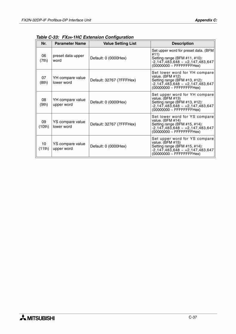
FX2N-32DP-IF Profibus-DP Interface Unit Appendix C:
C-37
06(7th)
preset data upper word
Default: 0 (0000Hex)
Set upper word for preset data. (BFM#11)Setting range (BFM #11, #10): -2,147,483,648 ~ +2,147,483,647(00000000 ~ FFFFFFFFHex)
07(8th)
YH compare value lower word
Default: 32767 (7FFFHex)
Set lower word for YH comparevalue. (BFM #12)Setting range (BFM #13, #12): -2,147,483,648 ~ +2,147,483,647(00000000 ~ FFFFFFFFHex)
08(9th)
YH compare value upper word
Default: 0 (0000Hex)
Set upper word for YH comparevalue. (BFM #13)Setting range (BFM #13, #12): -2,147,483,648 ~ +2,147,483,647(00000000 ~ FFFFFFFFHex)
09(10th)
YS compare value lower word
Default: 32767 (7FFFHex)
Set lower word for YS comparevalue. (BFM #14)Setting range (BFM #15, #14): -2,147,483,648 ~ +2,147,483,647(00000000 ~ FFFFFFFFHex)
10(11th)
YS compare value upper word
Default: 0 (0000Hex)
Set upper word for YS comparevalue. (BFM #15)Setting range (BFM #15, #14): -2,147,483,648 ~ +2,147,483,647(00000000 ~ FFFFFFFFHex)
Table C-33: FX2N-1HC Extension ConfigurationNr. Parameter Name Value Setting List Description
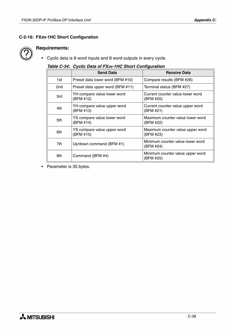
FX2N-32DP-IF Profibus-DP Interface Unit Appendix C:
C-38
C-2-16: FX2N-1HC Short Configuration
Requirements:
• Cyclic data is 8 word inputs and 8 word outputs in every cycle.
• Parameter is 35 bytes.
Table C-34: Cyclic Data of FX2N-1HC Short ConfigurationSend Data Receive Data
1st Preset data lower word (BFM #10) Compare results (BFM #26)
2nd Preset data upper word (BFM #11) Terminal status (BFM #27)
3rdYH compare value lower word (BFM #12)
Current counter value lower word (BFM #20)
4thYH compare value upper word (BFM #13)
Current counter value upper word (BFM #21)
5thYS compare value lower word (BFM #14)
Maximum counter value lower word (BFM #22)
6thYS compare value upper word (BFM #15)
Maximum counter value upper word (BFM #23)
7th Up/down command (BFM #1)Minimum counter value lower word (BFM #24)
8th Command (BFM #4)Minimum counter value upper word (BFM #25)
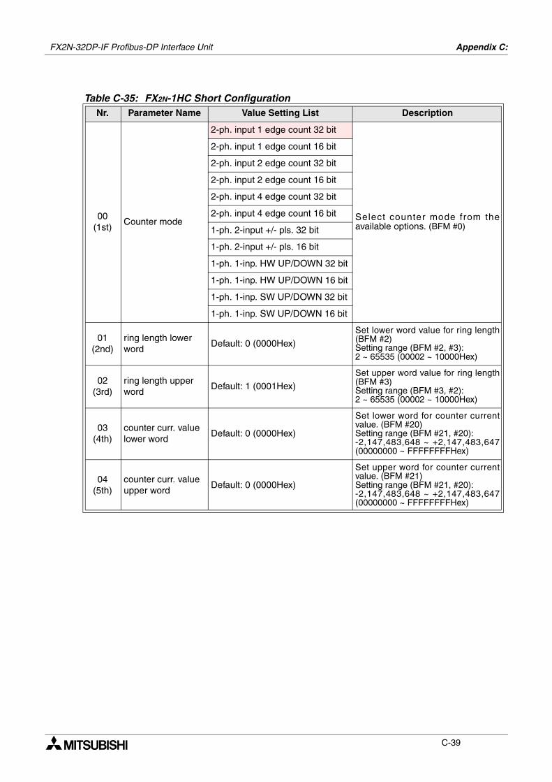
FX2N-32DP-IF Profibus-DP Interface Unit Appendix C:
C-39
Table C-35: FX2N-1HC Short ConfigurationNr. Parameter Name Value Setting List Description
00(1st)
Counter mode
2-ph. input 1 edge count 32 bit
Select counter mode from theavailable options. (BFM #0)
2-ph. input 1 edge count 16 bit
2-ph. input 2 edge count 32 bit
2-ph. input 2 edge count 16 bit
2-ph. input 4 edge count 32 bit
2-ph. input 4 edge count 16 bit
1-ph. 2-input +/- pls. 32 bit
1-ph. 2-input +/- pls. 16 bit
1-ph. 1-inp. HW UP/DOWN 32 bit
1-ph. 1-inp. HW UP/DOWN 16 bit
1-ph. 1-inp. SW UP/DOWN 32 bit
1-ph. 1-inp. SW UP/DOWN 16 bit
01(2nd)
ring length lower word
Default: 0 (0000Hex)
Set lower word value for ring length(BFM #2)Setting range (BFM #2, #3): 2 ~ 65535 (00002 ~ 10000Hex)
02(3rd)
ring length upper word
Default: 1 (0001Hex)
Set upper word value for ring length(BFM #3)Setting range (BFM #3, #2): 2 ~ 65535 (00002 ~ 10000Hex)
03(4th)
counter curr. value lower word
Default: 0 (0000Hex)
Set lower word for counter currentvalue. (BFM #20) Setting range (BFM #21, #20): -2,147,483,648 ~ +2,147,483,647(00000000 ~ FFFFFFFFHex)
04(5th)
counter curr. value upper word
Default: 0 (0000Hex)
Set upper word for counter currentvalue. (BFM #21)Setting range (BFM #21, #20): -2,147,483,648 ~ +2,147,483,647(00000000 ~ FFFFFFFFHex)
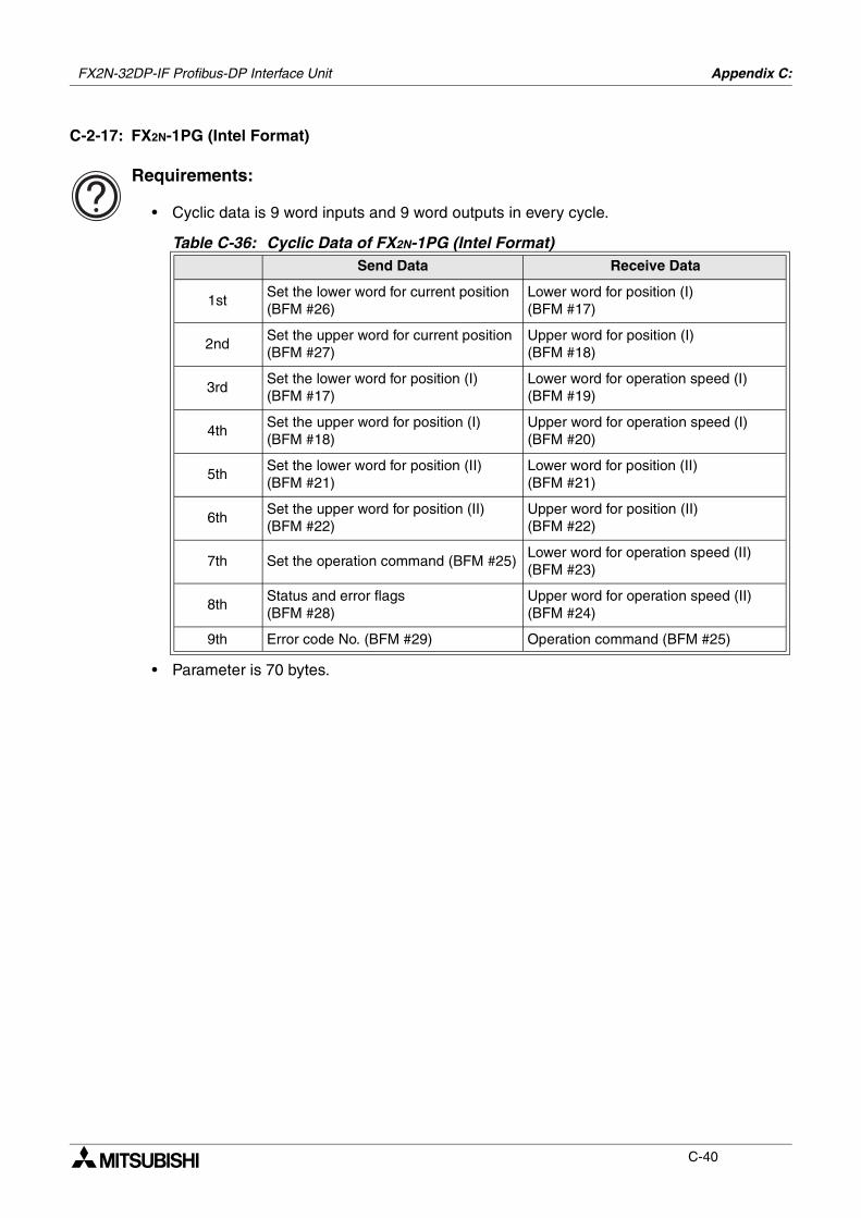
FX2N-32DP-IF Profibus-DP Interface Unit Appendix C:
C-40
C-2-17: FX2N-1PG (Intel Format)
Requirements:
• Cyclic data is 9 word inputs and 9 word outputs in every cycle.
• Parameter is 70 bytes.
Table C-36: Cyclic Data of FX2N-1PG (Intel Format)Send Data Receive Data
1stSet the lower word for current position (BFM #26)
Lower word for position (I) (BFM #17)
2ndSet the upper word for current position (BFM #27)
Upper word for position (I) (BFM #18)
3rdSet the lower word for position (I) (BFM #17)
Lower word for operation speed (I) (BFM #19)
4thSet the upper word for position (I) (BFM #18)
Upper word for operation speed (I) (BFM #20)
5thSet the lower word for position (II) (BFM #21)
Lower word for position (II)(BFM #21)
6thSet the upper word for position (II) (BFM #22)
Upper word for position (II)(BFM #22)
7th Set the operation command (BFM #25)Lower word for operation speed (II) (BFM #23)
8thStatus and error flags (BFM #28)
Upper word for operation speed (II) (BFM #24)
9th Error code No. (BFM #29) Operation command (BFM #25)
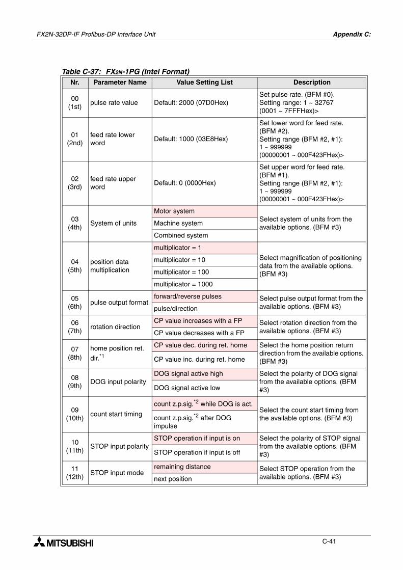
FX2N-32DP-IF Profibus-DP Interface Unit Appendix C:
C-41
Table C-37: FX2N-1PG (Intel Format)Nr. Parameter Name Value Setting List Description
00(1st)
pulse rate value Default: 2000 (07D0Hex)Set pulse rate. (BFM #0).Setting range: 1 ~ 32767 (0001 ~ 7FFFHex)>
01(2nd)
feed rate lower word
Default: 1000 (03E8Hex)
Set lower word for feed rate. (BFM #2).Setting range (BFM #2, #1): 1 ~ 999999 (00000001 ~ 000F423FHex)>
02(3rd)
feed rate upper word
Default: 0 (0000Hex)
Set upper word for feed rate. (BFM #1).Setting range (BFM #2, #1): 1 ~ 999999 (00000001 ~ 000F423FHex)>
03(4th)
System of units
Motor systemSelect system of units from the available options. (BFM #3)
Machine system
Combined system
04(5th)
position data multiplication
multiplicator = 1
Select magnification of positioning data from the available options. (BFM #3)
multiplicator = 10
multiplicator = 100
multiplicator = 1000
05(6th)
pulse output formatforward/reverse pulses Select pulse output format from the
available options. (BFM #3)pulse/direction
06(7th)
rotation directionCP value increases with a FP Select rotation direction from the
available options. (BFM #3)CP value decreases with a FP
07(8th)
home position ret.
dir.*1
CP value dec. during ret. home Select the home position return direction from the available options. (BFM #3)CP value inc. during ret. home
08(9th)
DOG input polarityDOG signal active high Select the polarity of DOG signal
from the available options. (BFM #3)DOG signal active low
09(10th)
count start timing
count z.p.sig.*2 while DOG is act.Select the count start timing from the available options. (BFM #3)count z.p.sig.*2 after DOG
impulse
10(11th)
STOP input polaritySTOP operation if input is on Select the polarity of STOP signal
from the available options. (BFM #3)STOP operation if input is off
11(12th)
STOP input moderemaining distance Select STOP operation from the
available options. (BFM #3)next position
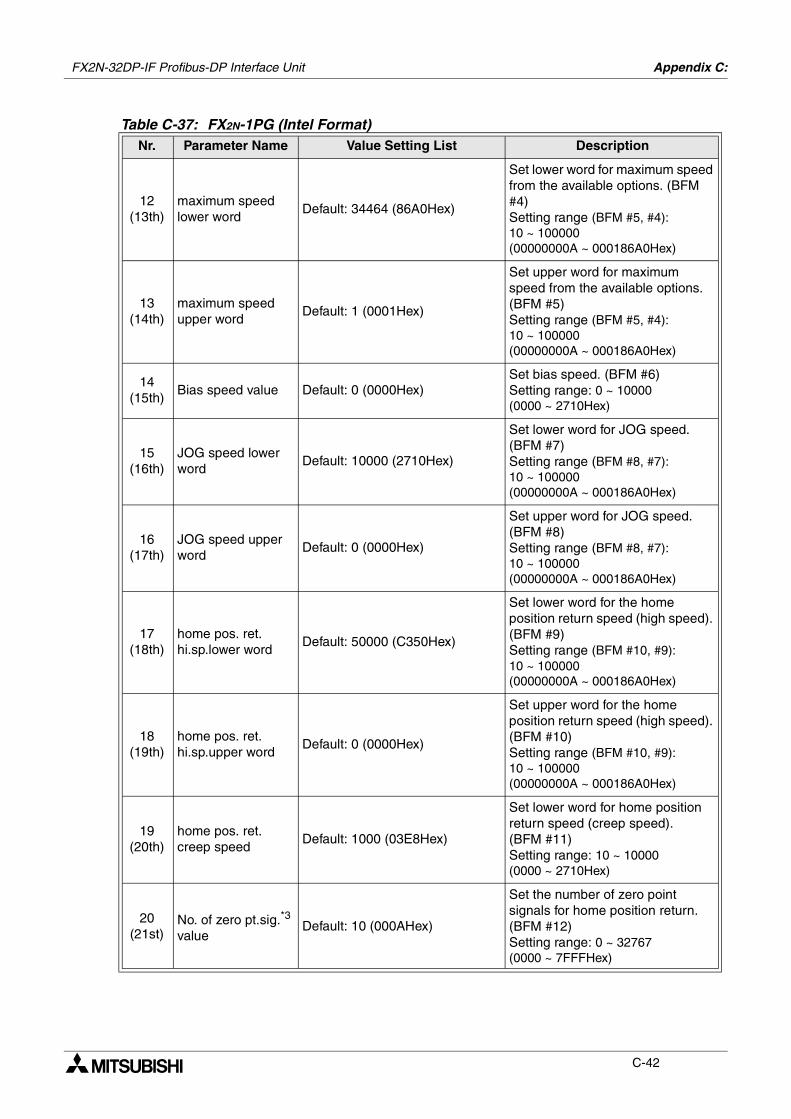
FX2N-32DP-IF Profibus-DP Interface Unit Appendix C:
C-42
12(13th)
maximum speed lower word
Default: 34464 (86A0Hex)
Set lower word for maximum speed from the available options. (BFM #4)Setting range (BFM #5, #4): 10 ~ 100000 (00000000A ~ 000186A0Hex)
13(14th)
maximum speed upper word
Default: 1 (0001Hex)
Set upper word for maximum speed from the available options. (BFM #5)Setting range (BFM #5, #4): 10 ~ 100000 (00000000A ~ 000186A0Hex)
14(15th)
Bias speed value Default: 0 (0000Hex)Set bias speed. (BFM #6)Setting range: 0 ~ 10000 (0000 ~ 2710Hex)
15(16th)
JOG speed lower word
Default: 10000 (2710Hex)
Set lower word for JOG speed. (BFM #7)Setting range (BFM #8, #7): 10 ~ 100000 (00000000A ~ 000186A0Hex)
16(17th)
JOG speed upper word
Default: 0 (0000Hex)
Set upper word for JOG speed. (BFM #8)Setting range (BFM #8, #7): 10 ~ 100000 (00000000A ~ 000186A0Hex)
17(18th)
home pos. ret. hi.sp.lower word
Default: 50000 (C350Hex)
Set lower word for the home position return speed (high speed). (BFM #9)Setting range (BFM #10, #9): 10 ~ 100000 (00000000A ~ 000186A0Hex)
18(19th)
home pos. ret. hi.sp.upper word
Default: 0 (0000Hex)
Set upper word for the home position return speed (high speed). (BFM #10)Setting range (BFM #10, #9): 10 ~ 100000 (00000000A ~ 000186A0Hex)
19(20th)
home pos. ret. creep speed
Default: 1000 (03E8Hex)
Set lower word for home position return speed (creep speed). (BFM #11)Setting range: 10 ~ 10000 (0000 ~ 2710Hex)
20(21st)
No. of zero pt.sig.*3 value
Default: 10 (000AHex)
Set the number of zero point signals for home position return. (BFM #12)Setting range: 0 ~ 32767 (0000 ~ 7FFFHex)
Table C-37: FX2N-1PG (Intel Format)Nr. Parameter Name Value Setting List Description
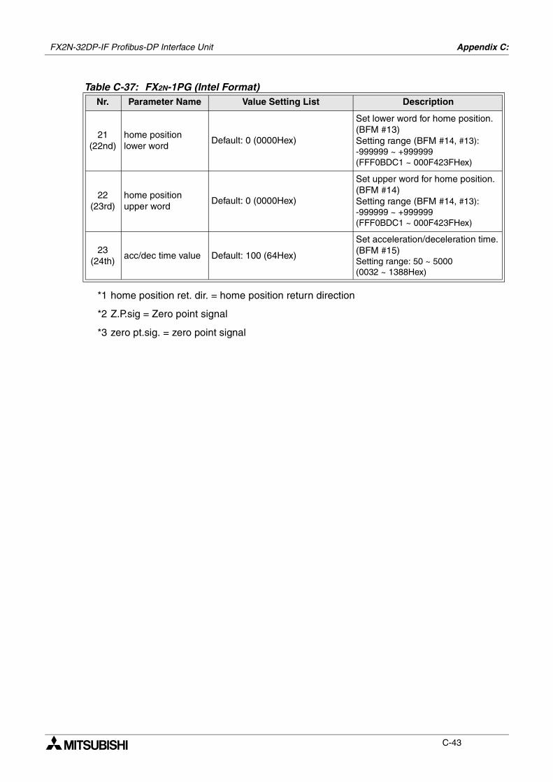
FX2N-32DP-IF Profibus-DP Interface Unit Appendix C:
C-43
*1 home position ret. dir. = home position return direction
*2 Z.P.sig = Zero point signal
*3 zero pt.sig. = zero point signal
21(22nd)
home position lower word
Default: 0 (0000Hex)
Set lower word for home position. (BFM #13)Setting range (BFM #14, #13): -999999 ~ +999999 (FFF0BDC1 ~ 000F423FHex)
22(23rd)
home position upper word
Default: 0 (0000Hex)
Set upper word for home position. (BFM #14)Setting range (BFM #14, #13): -999999 ~ +999999 (FFF0BDC1 ~ 000F423FHex)
23(24th)
acc/dec time value Default: 100 (64Hex)
Set acceleration/deceleration time. (BFM #15)Setting range: 50 ~ 5000 (0032 ~ 1388Hex)
Table C-37: FX2N-1PG (Intel Format)Nr. Parameter Name Value Setting List Description

FX2N-32DP-IF Profibus-DP Interface Unit Appendix C:
C-44
C-2-18: FX2N-1PG (Motorola Format)
Requirements:
• Cyclic data is 9 word inputs and 9 word outputs in every cycle.
• Parameter is 70 bytes.
Table C-38: Cyclic Data of FX2N-1PG (Motorola Format)Send Data Receive Data
1stSet the lower word for current position (BFM #26)
Lower word for position (I) (BFM #17)
2ndSet the upper word for current position (BFM #27)
Upper word for position (I) (BFM #18)
3rdSet the lower word for position (I) (BFM #17)
Lower word for operation speed (I) (BFM #19)
4thSet the upper word for position (I) (BFM #18)
Upper word for operation speed (I) (BFM #20)
5thSet the lower word for position (II) (BFM #21)
Lower word for position (II)(BFM #21)
6thSet the upper word for position (II) (BFM #22)
Upper word for position (II)(BFM #22)
7th Set the operation command (BFM #25)Lower word for operation speed (II) (BFM #23)
8thStatus and error flags (BFM #28)
Upper word for operation speed (II) (BFM #24)
9th Error code No. (BFM #29) Operation command (BFM #25)
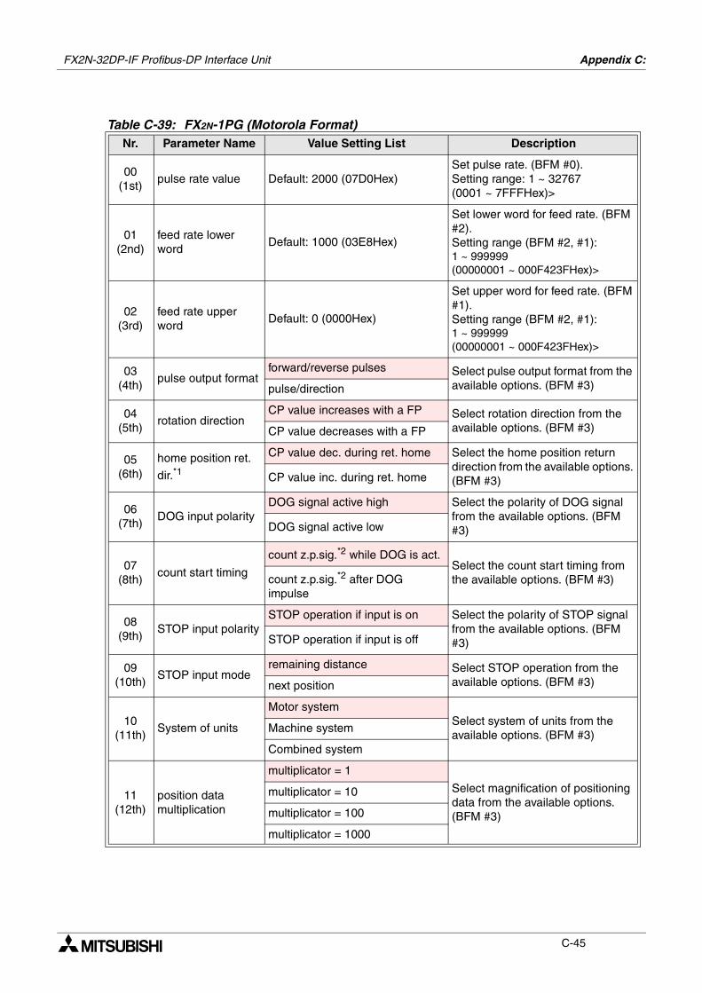
FX2N-32DP-IF Profibus-DP Interface Unit Appendix C:
C-45
Table C-39: FX2N-1PG (Motorola Format)Nr. Parameter Name Value Setting List Description
00(1st)
pulse rate value Default: 2000 (07D0Hex)Set pulse rate. (BFM #0).Setting range: 1 ~ 32767 (0001 ~ 7FFFHex)>
01(2nd)
feed rate lower word
Default: 1000 (03E8Hex)
Set lower word for feed rate. (BFM #2).Setting range (BFM #2, #1): 1 ~ 999999 (00000001 ~ 000F423FHex)>
02(3rd)
feed rate upper word
Default: 0 (0000Hex)
Set upper word for feed rate. (BFM #1).Setting range (BFM #2, #1): 1 ~ 999999 (00000001 ~ 000F423FHex)>
03(4th)
pulse output formatforward/reverse pulses Select pulse output format from the
available options. (BFM #3)pulse/direction
04(5th)
rotation directionCP value increases with a FP Select rotation direction from the
available options. (BFM #3)CP value decreases with a FP
05(6th)
home position ret.
dir.*1
CP value dec. during ret. home Select the home position return direction from the available options. (BFM #3)CP value inc. during ret. home
06(7th)
DOG input polarityDOG signal active high Select the polarity of DOG signal
from the available options. (BFM #3)DOG signal active low
07(8th)
count start timing
count z.p.sig.*2 while DOG is act.Select the count start timing from the available options. (BFM #3)count z.p.sig.*2 after DOG
impulse
08(9th)
STOP input polaritySTOP operation if input is on Select the polarity of STOP signal
from the available options. (BFM #3)STOP operation if input is off
09(10th)
STOP input moderemaining distance Select STOP operation from the
available options. (BFM #3)next position
10(11th)
System of units
Motor systemSelect system of units from the available options. (BFM #3)
Machine system
Combined system
11(12th)
position data multiplication
multiplicator = 1
Select magnification of positioning data from the available options. (BFM #3)
multiplicator = 10
multiplicator = 100
multiplicator = 1000
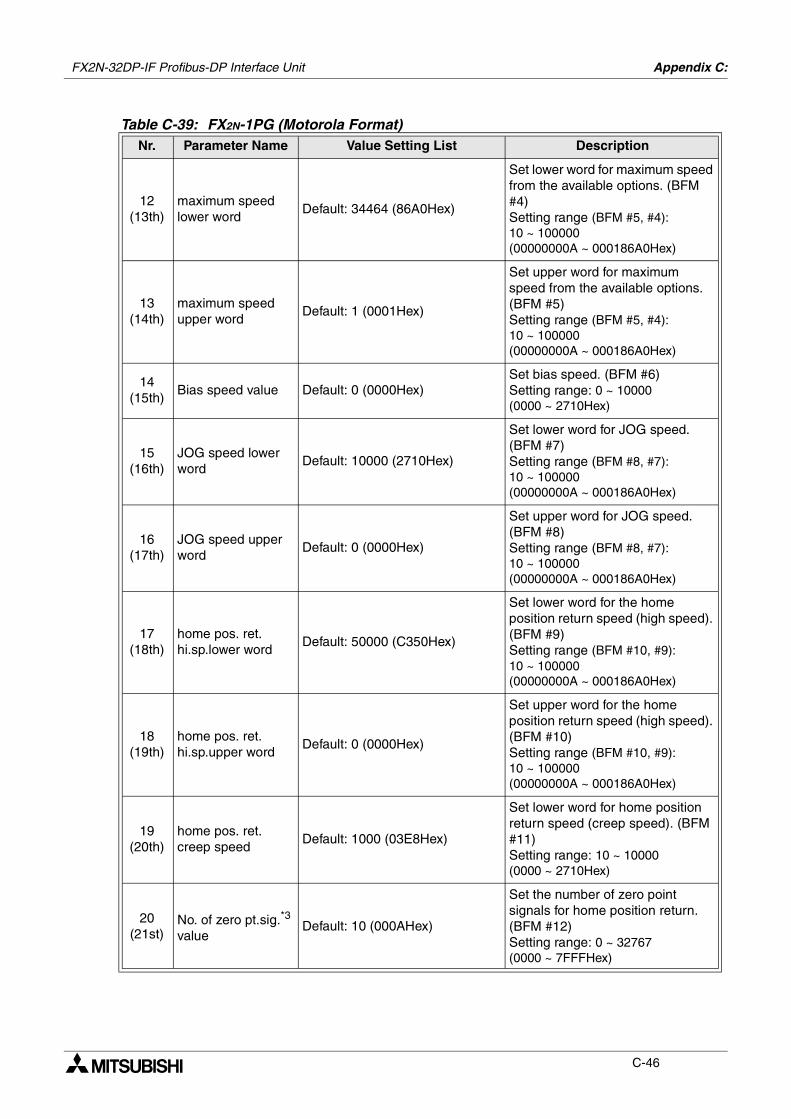
FX2N-32DP-IF Profibus-DP Interface Unit Appendix C:
C-46
12(13th)
maximum speed lower word
Default: 34464 (86A0Hex)
Set lower word for maximum speed from the available options. (BFM #4)Setting range (BFM #5, #4): 10 ~ 100000 (00000000A ~ 000186A0Hex)
13(14th)
maximum speed upper word
Default: 1 (0001Hex)
Set upper word for maximum speed from the available options. (BFM #5)Setting range (BFM #5, #4): 10 ~ 100000 (00000000A ~ 000186A0Hex)
14(15th)
Bias speed value Default: 0 (0000Hex)Set bias speed. (BFM #6)Setting range: 0 ~ 10000 (0000 ~ 2710Hex)
15(16th)
JOG speed lower word
Default: 10000 (2710Hex)
Set lower word for JOG speed. (BFM #7)Setting range (BFM #8, #7): 10 ~ 100000 (00000000A ~ 000186A0Hex)
16(17th)
JOG speed upper word
Default: 0 (0000Hex)
Set upper word for JOG speed. (BFM #8)Setting range (BFM #8, #7): 10 ~ 100000 (00000000A ~ 000186A0Hex)
17(18th)
home pos. ret. hi.sp.lower word
Default: 50000 (C350Hex)
Set lower word for the home position return speed (high speed). (BFM #9)Setting range (BFM #10, #9): 10 ~ 100000 (00000000A ~ 000186A0Hex)
18(19th)
home pos. ret. hi.sp.upper word
Default: 0 (0000Hex)
Set upper word for the home position return speed (high speed). (BFM #10)Setting range (BFM #10, #9): 10 ~ 100000 (00000000A ~ 000186A0Hex)
19(20th)
home pos. ret. creep speed
Default: 1000 (03E8Hex)
Set lower word for home position return speed (creep speed). (BFM #11)Setting range: 10 ~ 10000 (0000 ~ 2710Hex)
20(21st)
No. of zero pt.sig.*3 value
Default: 10 (000AHex)
Set the number of zero point signals for home position return. (BFM #12)Setting range: 0 ~ 32767 (0000 ~ 7FFFHex)
Table C-39: FX2N-1PG (Motorola Format)Nr. Parameter Name Value Setting List Description
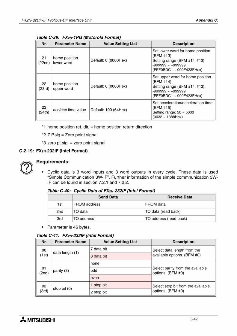
FX2N-32DP-IF Profibus-DP Interface Unit Appendix C:
C-47
*1 home position ret. dir. = home position return direction
*2 Z.P.sig = Zero point signal
*3 zero pt.sig. = zero point signal
C-2-19: FX2N-232IF (Intel Format)
Requirements:
• Cyclic data is 3 word inputs and 3 word outputs in every cycle. These data is used“Simple Communication 3W-IF”. Further information of the simple commnunication 3W-IF can be found in section 7.2.1 and 7.2.2.
• Parameter is 46 bytes.
21(22nd)
home position lower word
Default: 0 (0000Hex)
Set lower word for home position. (BFM #13)Setting range (BFM #14, #13): -999999 ~ +999999 (FFF0BDC1 ~ 000F423FHex)
22(23rd)
home position upper word
Default: 0 (0000Hex)
Set upper word for home position. (BFM #14)Setting range (BFM #14, #13): -999999 ~ +999999 (FFF0BDC1 ~ 000F423FHex)
23(24th)
acc/dec time value Default: 100 (64Hex)
Set acceleration/deceleration time. (BFM #15)Setting range: 50 ~ 5000 (0032 ~ 1388Hex)
Table C-40: Cyclic Data of FX2N-232IF (Intel Format)Send Data Receive Data
1st FROM address FROM data
2nd TO data TO data (read back)
3rd TO address TO address (read back)
Table C-41: FX2N-232IF (Intel Format)Nr. Parameter Name Value Setting List Description
00(1st)
data length (1)7 data bit Select data length from the
available options. (BFM #0)8 data bit
01(2nd)
parity (3)
noneSelect parity from the available options. (BFM #0)
odd
even
02(3rd)
stop bit (0)1 stop bit Select stop bit from the available
options. (BFM #0)2 stop bit
Table C-39: FX2N-1PG (Motorola Format)Nr. Parameter Name Value Setting List Description
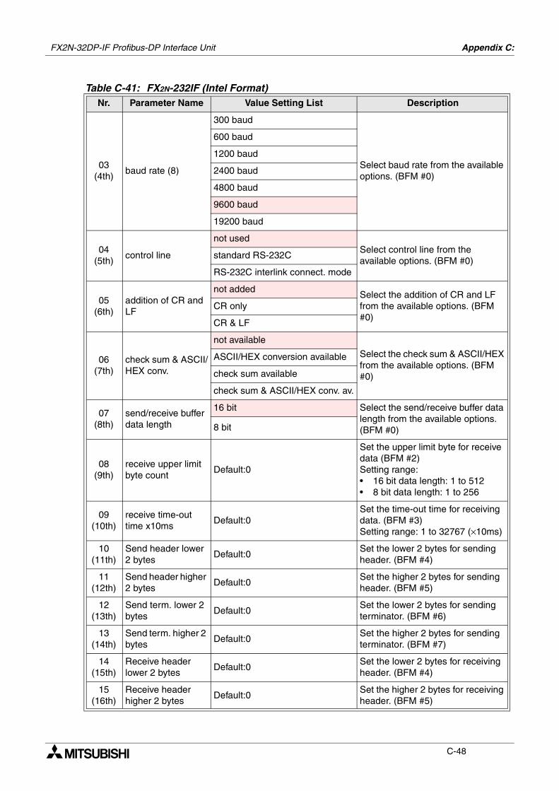
FX2N-32DP-IF Profibus-DP Interface Unit Appendix C:
C-48
03(4th)
baud rate (8)
300 baud
Select baud rate from the available options. (BFM #0)
600 baud
1200 baud
2400 baud
4800 baud
9600 baud
19200 baud
04(5th)
control line
not usedSelect control line from the available options. (BFM #0)
standard RS-232C
RS-232C interlink connect. mode
05(6th)
addition of CR and LF
not addedSelect the addition of CR and LF from the available options. (BFM #0)
CR only
CR & LF
06(7th)
check sum & ASCII/HEX conv.
not available
Select the check sum & ASCII/HEX from the available options. (BFM #0)
ASCII/HEX conversion available
check sum available
check sum & ASCII/HEX conv. av.
07(8th)
send/receive buffer data length
16 bit Select the send/receive buffer data length from the available options. (BFM #0)8 bit
08(9th)
receive upper limit byte count
Default:0
Set the upper limit byte for receive data (BFM #2)Setting range: • 16 bit data length: 1 to 512• 8 bit data length: 1 to 256
09(10th)
receive time-out time x10ms
Default:0Set the time-out time for receiving data. (BFM #3)Setting range: 1 to 32767 (×10ms)
10(11th)
Send header lower 2 bytes
Default:0Set the lower 2 bytes for sending header. (BFM #4)
11(12th)
Send header higher 2 bytes
Default:0Set the higher 2 bytes for sending header. (BFM #5)
12(13th)
Send term. lower 2 bytes
Default:0Set the lower 2 bytes for sending terminator. (BFM #6)
13(14th)
Send term. higher 2 bytes
Default:0Set the higher 2 bytes for sending terminator. (BFM #7)
14(15th)
Receive header lower 2 bytes
Default:0Set the lower 2 bytes for receiving header. (BFM #4)
15(16th)
Receive header higher 2 bytes
Default:0Set the higher 2 bytes for receiving header. (BFM #5)
Table C-41: FX2N-232IF (Intel Format)Nr. Parameter Name Value Setting List Description
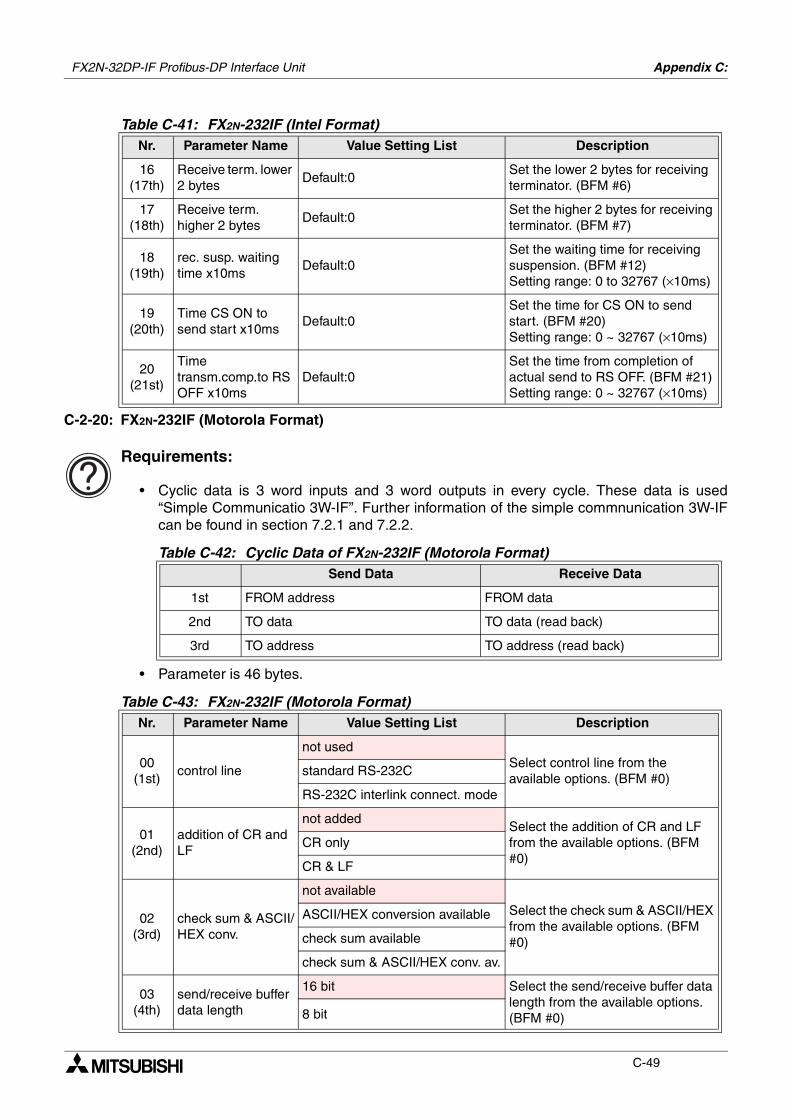
FX2N-32DP-IF Profibus-DP Interface Unit Appendix C:
C-49
C-2-20: FX2N-232IF (Motorola Format)
Requirements:
• Cyclic data is 3 word inputs and 3 word outputs in every cycle. These data is used“Simple Communicatio 3W-IF”. Further information of the simple commnunication 3W-IFcan be found in section 7.2.1 and 7.2.2.
• Parameter is 46 bytes.
16(17th)
Receive term. lower 2 bytes
Default:0Set the lower 2 bytes for receiving terminator. (BFM #6)
17(18th)
Receive term. higher 2 bytes
Default:0Set the higher 2 bytes for receiving terminator. (BFM #7)
18(19th)
rec. susp. waiting time x10ms
Default:0Set the waiting time for receiving suspension. (BFM #12)Setting range: 0 to 32767 (×10ms)
19(20th)
Time CS ON to send start x10ms
Default:0Set the time for CS ON to send start. (BFM #20)Setting range: 0 ~ 32767 (×10ms)
20(21st)
Time transm.comp.to RS OFF x10ms
Default:0Set the time from completion of actual send to RS OFF. (BFM #21)Setting range: 0 ~ 32767 (×10ms)
Table C-42: Cyclic Data of FX2N-232IF (Motorola Format)Send Data Receive Data
1st FROM address FROM data
2nd TO data TO data (read back)
3rd TO address TO address (read back)
Table C-43: FX2N-232IF (Motorola Format)Nr. Parameter Name Value Setting List Description
00(1st)
control line
not usedSelect control line from the available options. (BFM #0)
standard RS-232C
RS-232C interlink connect. mode
01(2nd)
addition of CR and LF
not addedSelect the addition of CR and LF from the available options. (BFM #0)
CR only
CR & LF
02(3rd)
check sum & ASCII/HEX conv.
not available
Select the check sum & ASCII/HEX from the available options. (BFM #0)
ASCII/HEX conversion available
check sum available
check sum & ASCII/HEX conv. av.
03(4th)
send/receive buffer data length
16 bit Select the send/receive buffer data length from the available options. (BFM #0)8 bit
Table C-41: FX2N-232IF (Intel Format)Nr. Parameter Name Value Setting List Description
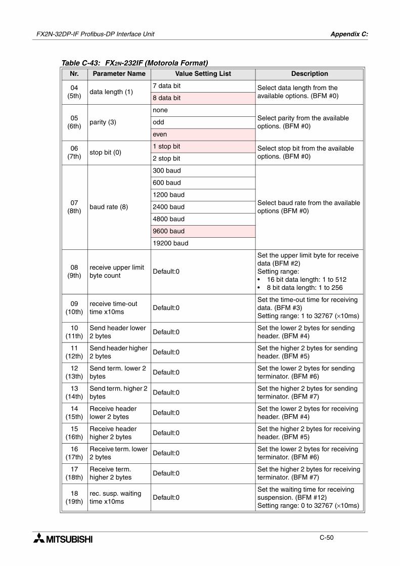
FX2N-32DP-IF Profibus-DP Interface Unit Appendix C:
C-50
04(5th)
data length (1)7 data bit Select data length from the
available options. (BFM #0)8 data bit
05(6th)
parity (3)
noneSelect parity from the available options. (BFM #0)
odd
even
06(7th)
stop bit (0)1 stop bit Select stop bit from the available
options. (BFM #0)2 stop bit
07(8th)
baud rate (8)
300 baud
Select baud rate from the available options (BFM #0)
600 baud
1200 baud
2400 baud
4800 baud
9600 baud
19200 baud
08(9th)
receive upper limit byte count
Default:0
Set the upper limit byte for receive data (BFM #2)Setting range: • 16 bit data length: 1 to 512• 8 bit data length: 1 to 256
09(10th)
receive time-out time x10ms
Default:0Set the time-out time for receiving data. (BFM #3)Setting range: 1 to 32767 (×10ms)
10(11th)
Send header lower 2 bytes
Default:0Set the lower 2 bytes for sending header. (BFM #4)
11(12th)
Send header higher 2 bytes
Default:0Set the higher 2 bytes for sending header. (BFM #5)
12(13th)
Send term. lower 2 bytes
Default:0Set the lower 2 bytes for sending terminator. (BFM #6)
13(14th)
Send term. higher 2 bytes
Default:0Set the higher 2 bytes for sending terminator. (BFM #7)
14(15th)
Receive header lower 2 bytes
Default:0Set the lower 2 bytes for receiving header. (BFM #4)
15(16th)
Receive header higher 2 bytes
Default:0Set the higher 2 bytes for receiving header. (BFM #5)
16(17th)
Receive term. lower 2 bytes
Default:0Set the lower 2 bytes for receiving terminator. (BFM #6)
17(18th)
Receive term. higher 2 bytes
Default:0Set the higher 2 bytes for receiving terminator. (BFM #7)
18(19th)
rec. susp. waiting time x10ms
Default:0Set the waiting time for receiving suspension. (BFM #12)Setting range: 0 to 32767 (×10ms)
Table C-43: FX2N-232IF (Motorola Format)Nr. Parameter Name Value Setting List Description
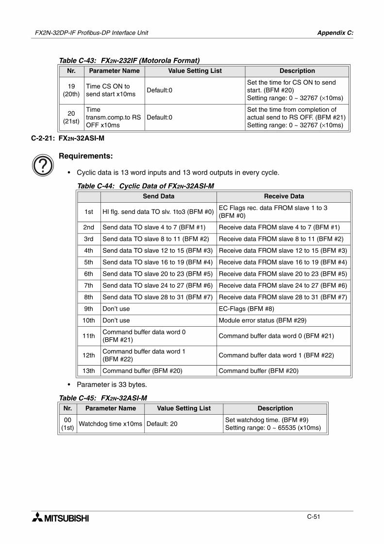
FX2N-32DP-IF Profibus-DP Interface Unit Appendix C:
C-51
C-2-21: FX2N-32ASI-M
Requirements:
• Cyclic data is 13 word inputs and 13 word outputs in every cycle.
• Parameter is 33 bytes.
19(20th)
Time CS ON to send start x10ms
Default:0Set the time for CS ON to send start. (BFM #20)Setting range: 0 ~ 32767 (×10ms)
20(21st)
Time transm.comp.to RS OFF x10ms
Default:0Set the time from completion of actual send to RS OFF. (BFM #21)Setting range: 0 ~ 32767 (×10ms)
Table C-44: Cyclic Data of FX2N-32ASI-MSend Data Receive Data
1st HI flg. send data TO slv. 1to3 (BFM #0)EC Flags rec. data FROM slave 1 to 3 (BFM #0)
2nd Send data TO slave 4 to 7 (BFM #1) Receive data FROM slave 4 to 7 (BFM #1)
3rd Send data TO slave 8 to 11 (BFM #2) Receive data FROM slave 8 to 11 (BFM #2)
4th Send data TO slave 12 to 15 (BFM #3) Receive data FROM slave 12 to 15 (BFM #3)
5th Send data TO slave 16 to 19 (BFM #4) Receive data FROM slave 16 to 19 (BFM #4)
6th Send data TO slave 20 to 23 (BFM #5) Receive data FROM slave 20 to 23 (BFM #5)
7th Send data TO slave 24 to 27 (BFM #6) Receive data FROM slave 24 to 27 (BFM #6)
8th Send data TO slave 28 to 31 (BFM #7) Receive data FROM slave 28 to 31 (BFM #7)
9th Don’t use EC-Flags (BFM #8)
10th Don’t use Module error status (BFM #29)
11thCommand buffer data word 0 (BFM #21)
Command buffer data word 0 (BFM #21)
12thCommand buffer data word 1 (BFM #22)
Command buffer data word 1 (BFM #22)
13th Command buffer (BFM #20) Command buffer (BFM #20)
Table C-45: FX2N-32ASI-MNr. Parameter Name Value Setting List Description
00(1st)
Watchdog time x10ms Default: 20Set watchdog time. (BFM #9)Setting range: 0 ~ 65535 (x10ms)
Table C-43: FX2N-232IF (Motorola Format)Nr. Parameter Name Value Setting List Description
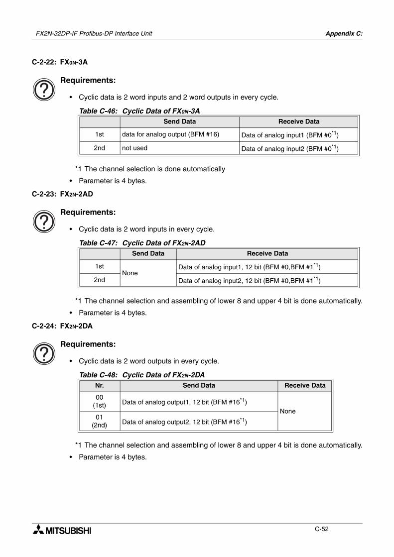
FX2N-32DP-IF Profibus-DP Interface Unit Appendix C:
C-52
C-2-22: FX0N-3A
Requirements:
• Cyclic data is 2 word inputs and 2 word outputs in every cycle.
*1 The channel selection is done automatically
• Parameter is 4 bytes.
C-2-23: FX2N-2AD
Requirements:
• Cyclic data is 2 word inputs in every cycle.
*1 The channel selection and assembling of lower 8 and upper 4 bit is done automatically.
• Parameter is 4 bytes.
C-2-24: FX2N-2DA
Requirements:
• Cyclic data is 2 word outputs in every cycle.
*1 The channel selection and assembling of lower 8 and upper 4 bit is done automatically.
• Parameter is 4 bytes.
Table C-46: Cyclic Data of FX0N-3ASend Data Receive Data
1st data for analog output (BFM #16) Data of analog input1 (BFM #0*1)
2nd not used Data of analog input2 (BFM #0*1)
Table C-47: Cyclic Data of FX2N-2ADSend Data Receive Data
1stNone
Data of analog input1, 12 bit (BFM #0,BFM #1*1)
2nd Data of analog input2, 12 bit (BFM #0,BFM #1*1)
Table C-48: Cyclic Data of FX2N-2DANr. Send Data Receive Data
00(1st) Data of analog output1, 12 bit (BFM #16*1)
None01
(2nd) Data of analog output2, 12 bit (BFM #16*1)
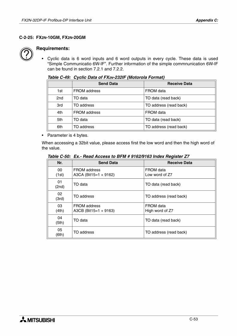
FX2N-32DP-IF Profibus-DP Interface Unit Appendix C:
C-53
C-2-25: FX2N-10GM, FX2N-20GM
Requirements:
• Cyclic data is 6 word inputs and 6 word outputs in every cycle. These data is used“Simple Communicatio 6W-IF”. Further information of the simple commnunication 6W-IFcan be found in section 7.2.1 and 7.2.2.
• Parameter is 4 bytes.
When accessing a 32bit value, please access first the low word and then the high word of the value.
Table C-49: Cyclic Data of FX2N-232IF (Motorola Format)Send Data Receive Data
1st FROM address FROM data
2nd TO data TO data (read back)
3rd TO address TO address (read back)
4th FROM address FROM data
5th TO data TO data (read back)
6th TO address TO address (read back)
Table C-50: Ex.- Read Access to BFM # 9162/9163 Index Register Z7Nr. Send Data Receive Data
00(1st)
FROM addressA3CA (Bit15=1 + 9162)
FROM dataLow word of Z7
01(2nd)
TO data TO data (read back)
02(3rd)
TO address TO address (read back)
03(4th)
FROM addressA3CB (Bit15=1 + 9163)
FROM dataHigh word of Z7
04(5th)
TO data TO data (read back)
05(6th)
TO address TO address (read back)
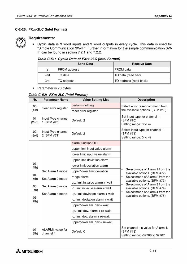
FX2N-32DP-IF Profibus-DP Interface Unit Appendix C:
C-54
C-2-26: FX2N-2LC (Intel Format)
Requirements:
• Cyclic data is 3 word inputs and 3 word outputs in every cycle. This data is used for“Simple Communication 3W-IF”. Further information for the simple commnunication 3W-IF can be found in section 7.2.1 and 7.2.2.
• Parameter is 70 bytes.
Table C-51: Cyclic Data of FX2N-2LC (Intel Format)Send Data Receive Data
1st FROM address FROM data
2nd TO data TO data (read back)
3rd TO address TO address (read back)
Table C-52: FX2N-2LC (Intel Format)Nr. Parameter Name Value Setting List Description
00(1st)
clear error registerperform nothing Select error reset command from
the available options. (BFM #10).reset error register
01(2nd)
Input Type channel 1 (BFM #70)
Default: 2Set input type for channel 1. (BFM #70)Setting range: 0 to 42
02(3rd)
Input Type channel 2 (BFM #71)
Default: 2Select input type for channel 1. (BFM #71)Setting range: 0 to 42
03(4th)
04(5th)
05(6th)
06(7th)
Set Alarm 1 mode
Set Alarm 2 mode
Set Alarm 3 mode
Set Alarm 4 mode
alarm function OFF
• Select mode of Alarm 1 from the available options. (BFM #72)
• Select mode of Alarm 2 from the available options. (BFM #73)
• Select mode of Alarm 3 from the available options. (BFM #74)
• Select mode of Alarm 4 from the available options. (BFM #75)
upper limit input value alarm
lower limit input value alarm
upper limit deviation alarm
lower limit deviation alarm
upper/lower limit deviation
range alarm
up. limit in.value alarm + wait
lo. limit in.value alarm + wait
up. limit deviation alarm + wait
lo. limit deviation alarm + wait
upper/lower lim. dev.+ wait
up. limit dev. alarm + re-wait
lo. limit dev. alarm + re-wait
upper/lower lim. dev.+ re-wait
07(8th)
ALARM1 value for channel 1.
Default: 0Set channel 1’s value for Alarm 1. (BFM #13)Setting range: -32768 to 32767
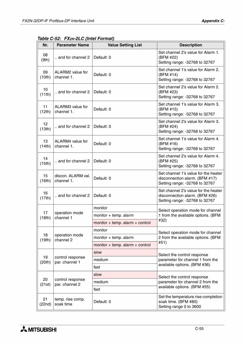
FX2N-32DP-IF Profibus-DP Interface Unit Appendix C:
C-55
08(9th)
.. and for channel 2 Default: 0Set channel 2’s value for Alarm 1. (BFM #22)Setting range: -32768 to 32767
09(10th)
ALARM2 value for channel 1.
Default: 0Set channel 1’s value for Alarm 2. (BFM #14)Setting range: -32768 to 32767
10(11th)
.. and for channel 2 Default: 0Set channel 2’s value for Alarm 2. (BFM #23)Setting range: -32768 to 32767
11(12th)
ALARM3 value for channel 1.
Default: 0Set channel 1’s value for Alarm 3. (BFM #15)Setting range: -32768 to 32767
12(13th)
.. and for channel 2 Default: 0Set channel 2’s value for Alarm 3. (BFM #24)Setting range: -32768 to 32767
13(14th)
ALARM4 value for channel 1.
Default: 0Set channel 1’s value for Alarm 4. (BFM #16)Setting range: -32768 to 32767
14(15th)
.. and for channel 2 Default: 0Set channel 2’s value for Alarm 4. (BFM #25)Setting range: -32768 to 32767
15(16th)
discon. ALARM val. channel 1.
Default: 0Set channel 1’s value for the heater disconnection alarm. (BFM #17)Setting range: -32768 to 32767
16(17th)
.. and for channel 2 Default: 0Set channel 2’s value for the heater disconnection alarm. (BFM #26)Setting range: -32768 to 32767
17(18th)
operation mode channel 1
monitorSelect operation mode for channel 1 from the available options. (BFM #32)
monitor + temp. alarm
monitor + temp. alarm + control
18(19th)
operation mode channel 2
monitorSelect operation mode for channel 2 from the available options. (BFM #51)
monitor + temp. alarm
monitor + temp. alarm + control
19(20th)
control response par. channel 1
slowSelect the control response parameter for channel 1 from the available options. (BFM #36)
medium
fast
20(21st)
control response par. channel 2
slowSelect the control response parameter for channel 2 from the available options. (BFM #55)
medium
fast
21(22nd)
temp. rise comp. soak time
Default: 0Set the temperature rise completion soak time. (BFM #80)Setting range 0 to 3600
Table C-52: FX2N-2LC (Intel Format)Nr. Parameter Name Value Setting List Description
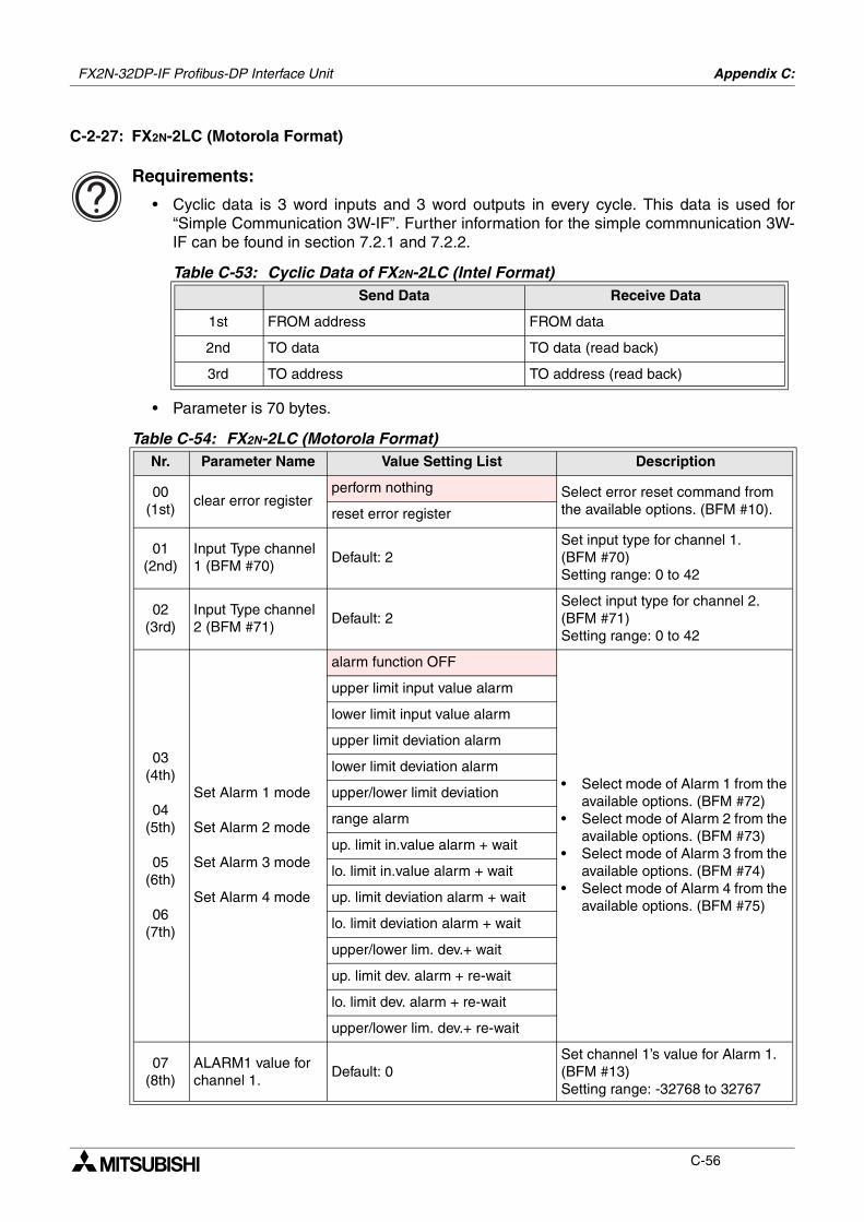
FX2N-32DP-IF Profibus-DP Interface Unit Appendix C:
C-56
C-2-27: FX2N-2LC (Motorola Format)
Requirements:
• Cyclic data is 3 word inputs and 3 word outputs in every cycle. This data is used for“Simple Communication 3W-IF”. Further information for the simple commnunication 3W-IF can be found in section 7.2.1 and 7.2.2.
• Parameter is 70 bytes.
Table C-53: Cyclic Data of FX2N-2LC (Intel Format)Send Data Receive Data
1st FROM address FROM data
2nd TO data TO data (read back)
3rd TO address TO address (read back)
Table C-54: FX2N-2LC (Motorola Format)Nr. Parameter Name Value Setting List Description
00(1st)
clear error registerperform nothing Select error reset command from
the available options. (BFM #10).reset error register
01(2nd)
Input Type channel 1 (BFM #70)
Default: 2Set input type for channel 1. (BFM #70)Setting range: 0 to 42
02(3rd)
Input Type channel 2 (BFM #71)
Default: 2Select input type for channel 2. (BFM #71)Setting range: 0 to 42
03(4th)
04(5th)
05(6th)
06(7th)
Set Alarm 1 mode
Set Alarm 2 mode
Set Alarm 3 mode
Set Alarm 4 mode
alarm function OFF
• Select mode of Alarm 1 from the available options. (BFM #72)
• Select mode of Alarm 2 from the available options. (BFM #73)
• Select mode of Alarm 3 from the available options. (BFM #74)
• Select mode of Alarm 4 from the available options. (BFM #75)
upper limit input value alarm
lower limit input value alarm
upper limit deviation alarm
lower limit deviation alarm
upper/lower limit deviation
range alarm
up. limit in.value alarm + wait
lo. limit in.value alarm + wait
up. limit deviation alarm + wait
lo. limit deviation alarm + wait
upper/lower lim. dev.+ wait
up. limit dev. alarm + re-wait
lo. limit dev. alarm + re-wait
upper/lower lim. dev.+ re-wait
07(8th)
ALARM1 value for channel 1.
Default: 0Set channel 1’s value for Alarm 1. (BFM #13)Setting range: -32768 to 32767
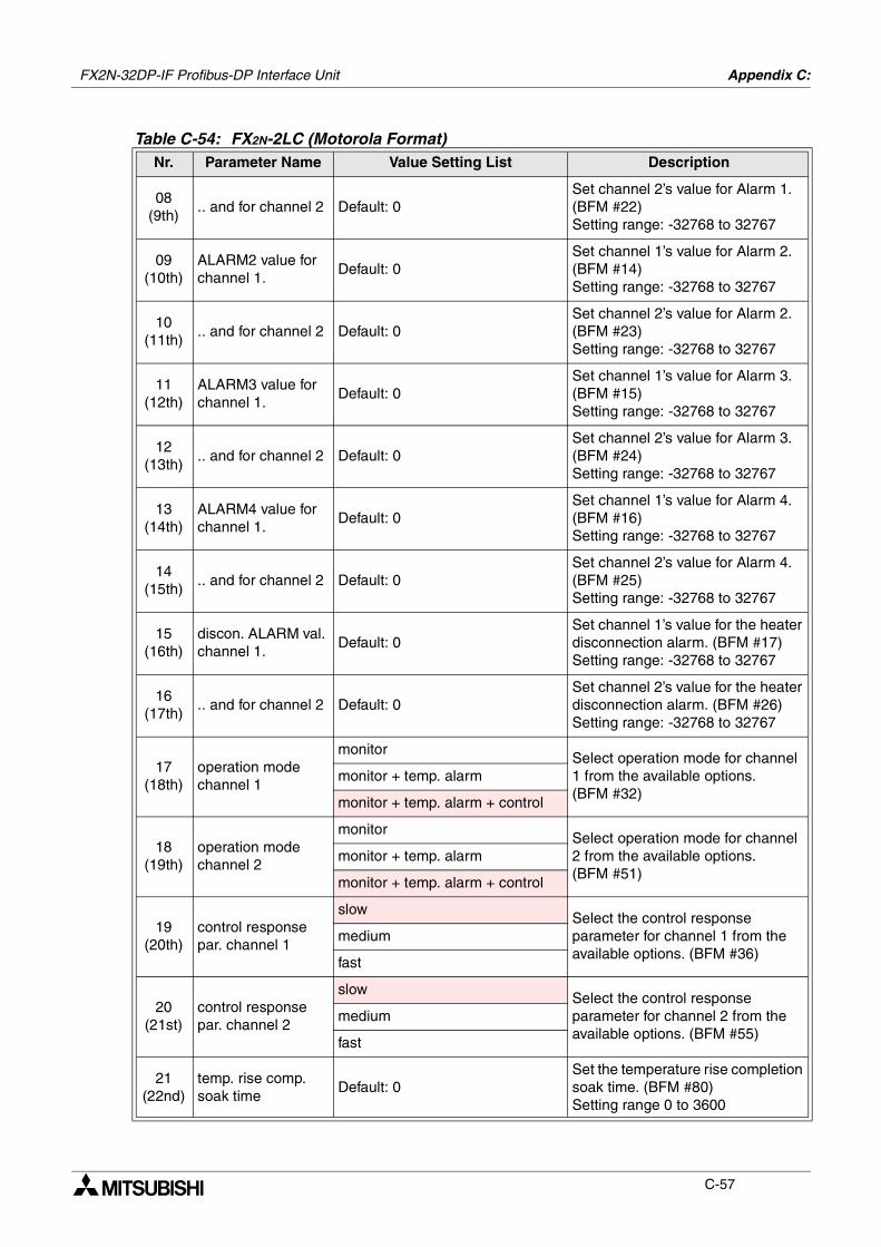
FX2N-32DP-IF Profibus-DP Interface Unit Appendix C:
C-57
08(9th)
.. and for channel 2 Default: 0Set channel 2’s value for Alarm 1. (BFM #22)Setting range: -32768 to 32767
09(10th)
ALARM2 value for channel 1.
Default: 0Set channel 1’s value for Alarm 2. (BFM #14)Setting range: -32768 to 32767
10(11th)
.. and for channel 2 Default: 0Set channel 2’s value for Alarm 2. (BFM #23)Setting range: -32768 to 32767
11(12th)
ALARM3 value for channel 1.
Default: 0Set channel 1’s value for Alarm 3. (BFM #15)Setting range: -32768 to 32767
12(13th)
.. and for channel 2 Default: 0Set channel 2’s value for Alarm 3. (BFM #24)Setting range: -32768 to 32767
13(14th)
ALARM4 value for channel 1.
Default: 0Set channel 1’s value for Alarm 4. (BFM #16)Setting range: -32768 to 32767
14(15th)
.. and for channel 2 Default: 0Set channel 2’s value for Alarm 4. (BFM #25)Setting range: -32768 to 32767
15(16th)
discon. ALARM val. channel 1.
Default: 0Set channel 1’s value for the heater disconnection alarm. (BFM #17)Setting range: -32768 to 32767
16(17th)
.. and for channel 2 Default: 0Set channel 2’s value for the heater disconnection alarm. (BFM #26)Setting range: -32768 to 32767
17(18th)
operation mode channel 1
monitorSelect operation mode for channel 1 from the available options. (BFM #32)
monitor + temp. alarm
monitor + temp. alarm + control
18(19th)
operation mode channel 2
monitorSelect operation mode for channel 2 from the available options. (BFM #51)
monitor + temp. alarm
monitor + temp. alarm + control
19(20th)
control response par. channel 1
slowSelect the control response parameter for channel 1 from the available options. (BFM #36)
medium
fast
20(21st)
control response par. channel 2
slowSelect the control response parameter for channel 2 from the available options. (BFM #55)
medium
fast
21(22nd)
temp. rise comp. soak time
Default: 0Set the temperature rise completion soak time. (BFM #80)Setting range 0 to 3600
Table C-54: FX2N-2LC (Motorola Format)Nr. Parameter Name Value Setting List Description
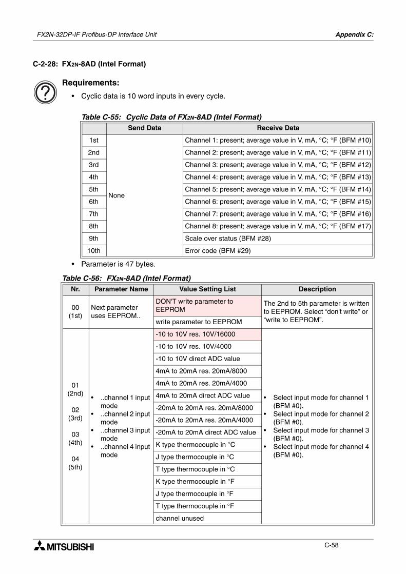
FX2N-32DP-IF Profibus-DP Interface Unit Appendix C:
C-58
C-2-28: FX2N-8AD (Intel Format)
Requirements:
• Cyclic data is 10 word inputs in every cycle.
• Parameter is 47 bytes.
Table C-55: Cyclic Data of FX2N-8AD (Intel Format)Send Data Receive Data
1st
None
Channel 1: present; average value in V, mA, °C; °F (BFM #10)
2nd Channel 2: present; average value in V, mA, °C; °F (BFM #11)
3rd Channel 3: present; average value in V, mA, °C; °F (BFM #12)
4th Channel 4: present; average value in V, mA, °C; °F (BFM #13)
5th Channel 5: present; average value in V, mA, °C; °F (BFM #14)
6th Channel 6: present; average value in V, mA, °C; °F (BFM #15)
7th Channel 7: present; average value in V, mA, °C; °F (BFM #16)
8th Channel 8: present; average value in V, mA, °C; °F (BFM #17)
9th Scale over status (BFM #28)
10th Error code (BFM #29)
Table C-56: FX2N-8AD (Intel Format)Nr. Parameter Name Value Setting List Description
00(1st)
Next parameter uses EEPROM..
DON'T write parameter to EEPROM
The 2nd to 5th parameter is written to EEPROM. Select “don't write” or “write to EEPROM”.write parameter to EEPROM
01(2nd)
02(3rd)
03(4th)
04(5th)
• ..channel 1 input mode
• ..channel 2 input mode
• ..channel 3 input mode
• ..channel 4 input mode
-10 to 10V res. 10V/16000
• Select input mode for channel 1 (BFM #0).
• Select input mode for channel 2 (BFM #0).
• Select input mode for channel 3 (BFM #0).
• Select input mode for channel 4 (BFM #0).
-10 to 10V res. 10V/4000
-10 to 10V direct ADC value
4mA to 20mA res. 20mA/8000
4mA to 20mA res. 20mA/4000
4mA to 20mA direct ADC value
-20mA to 20mA res. 20mA/8000
-20mA to 20mA res. 20mA/4000
-20mA to 20mA direct ADC value
K type thermocouple in °C
J type thermocouple in °C
T type thermocouple in °C
K type thermocouple in °F
J type thermocouple in °F
T type thermocouple in °F
channel unused
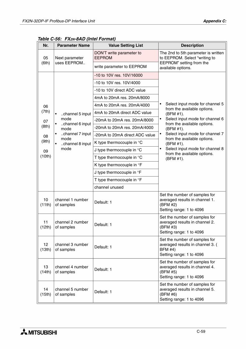
FX2N-32DP-IF Profibus-DP Interface Unit Appendix C:
C-59
05(6th)
Next parameter uses EEPROM..
DON'T write parameter to EEPROM
The 2nd to 5th parameter is written to EEPROM. Select “writing to EEPROM” setting from the available options.write parameter to EEPROM
06(7th)
07(8th)
08(9th)
09(10th)
• ..channel 5 input mode
• ..channel 6 input mode
• ..channel 7 input mode
• ..channel 8 input mode
-10 to 10V res. 10V/16000
• Select input mode for channel 5 from the available options. (BFM #1).
• Select input mode for channel 6 from the available options. (BFM #1).
• Select input mode for channel 7 from the available options. (BFM #1).
• Select input mode for channel 8 from the available options. (BFM #1).
-10 to 10V res. 10V/4000
-10 to 10V direct ADC value
4mA to 20mA res. 20mA/8000
4mA to 20mA res. 20mA/4000
4mA to 20mA direct ADC value
-20mA to 20mA res. 20mA/8000
-20mA to 20mA res. 20mA/4000
-20mA to 20mA direct ADC value
K type thermocouple in °C
J type thermocouple in °C
T type thermocouple in °C
K type thermocouple in °F
J type thermocouple in °F
T type thermocouple in °F
channel unused
10(11th)
channel 1 number of samples
Default: 1
Set the number of samples for averaged results in channel 1. (BFM #2)Setting range: 1 to 4096
11(12th)
channel 2 number of samples
Default: 1
Set the number of samples for averaged results in channel 2. (BFM #3)Setting range: 1 to 4096
12(13th)
channel 3 number of samples
Default: 1
Set the number of samples for averaged results in channel 3. (BFM #4)Setting range: 1 to 4096
13(14th)
channel 4 number of samples
Default: 1
Set the number of samples for averaged results in channel 4. (BFM #5)Setting range: 1 to 4096
14(15th)
channel 5 number of samples
Default: 1
Set the number of samples for averaged results in channel 5. (BFM #6)Setting range: 1 to 4096
Table C-56: FX2N-8AD (Intel Format)Nr. Parameter Name Value Setting List Description

FX2N-32DP-IF Profibus-DP Interface Unit Appendix C:
C-60
15(16th)
channel 6 number of samples
Default: 1
Set the number of samples for averaged results in channel 6. (BFM #7)Setting range: 1 to 4096
16(17th)
channel 7 number of samples
Default: 1
Set the number of samples for averaged results in channel 7. (BFM #8)Setting range: 1 to 4096
17(18th)
channel 8 number of samples
Default: 1
Set the number of samples for averaged results in channel 8. (BFM #9)Setting range: 1 to 4096
Table C-56: FX2N-8AD (Intel Format)Nr. Parameter Name Value Setting List Description

FX2N-32DP-IF Profibus-DP Interface Unit Appendix C:
C-61
C-2-29: FX2N-8AD (Motorola Format)
Requirements:
• Cyclic data is 10 word inputs in every cycle.
• Parameter is 47 bytes.
Table C-57: Cyclic Data of FX2N-8AD (Motorola Format)Send Data Receive Data
1st
None
Channel 1: present; average value in V, mA, °C; °F (BFM #10)
2nd Channel 2: present; average value in V, mA, °C; °F (BFM #11)
3rd Channel 3: present; average value in V, mA, °C; °F (BFM #12)
4th Channel 4: present; average value in V, mA, °C; °F (BFM #13)
5th Channel 5: present; average value in V, mA, °C; °F (BFM #14)
6th Channel 6: present; average value in V, mA, °C; °F (BFM #15)
7th Channel 7: present; average value in V, mA, °C; °F (BFM #16)
8th Channel 8: present; average value in V, mA, °C; °F (BFM #17)
9th Scale over status (BFM #28)
10th Error code (BFM #29)
Table C-58: FX2N-8AD (Motorola Format)Nr. Parameter Name Value Setting List Description
00(1st)
Next parameter uses EEPROM..
DON'T write parameter to EEPROM
The 2nd to 5th parameter is written to EEPROM. Select “don't write” or “write to EEPROM”.write parameter to EEPROM
01(2nd)
02(3rd)
03(4th)
04(5th)
• ..channel 3 input mode
• ..channel 4 input mode
• ..channel 1 input mode
• ..channel 2 input mode
-10 to 10V res. 10V/16000
• Select input mode for channel 3 (BFM #0).
• Select input mode for channel 4 (BFM #0).
• Select input mode for channel 1 (BFM #0).
• Select input mode for channel 2 (BFM #0).
-10 to 10V res. 10V/4000
-10 to 10V direct ADC value
4mA to 20mA res. 20mA/8000
4mA to 20mA res. 20mA/4000
4mA to 20mA direct ADC value
-20mA to 20mA res. 20mA/8000
-20mA to 20mA res. 20mA/4000
-20mA to 20mA direct ADC value
K type thermocouple in °C
J type thermocouple in °C
T type thermocouple in °C
K type thermocouple in °F
J type thermocouple in °F
T type thermocouple in °F
channel unused
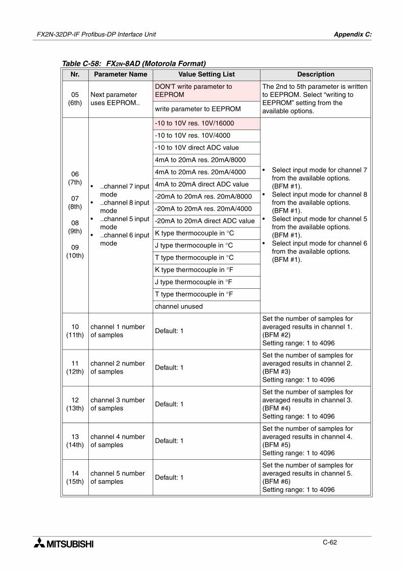
FX2N-32DP-IF Profibus-DP Interface Unit Appendix C:
C-62
05(6th)
Next parameter uses EEPROM..
DON'T write parameter to EEPROM
The 2nd to 5th parameter is written to EEPROM. Select “writing to EEPROM” setting from the available options.write parameter to EEPROM
06(7th)
07(8th)
08(9th)
09(10th)
• ..channel 7 input mode
• ..channel 8 input mode
• ..channel 5 input mode
• ..channel 6 input mode
-10 to 10V res. 10V/16000
• Select input mode for channel 7 from the available options. (BFM #1).
• Select input mode for channel 8 from the available options. (BFM #1).
• Select input mode for channel 5 from the available options. (BFM #1).
• Select input mode for channel 6 from the available options. (BFM #1).
-10 to 10V res. 10V/4000
-10 to 10V direct ADC value
4mA to 20mA res. 20mA/8000
4mA to 20mA res. 20mA/4000
4mA to 20mA direct ADC value
-20mA to 20mA res. 20mA/8000
-20mA to 20mA res. 20mA/4000
-20mA to 20mA direct ADC value
K type thermocouple in °C
J type thermocouple in °C
T type thermocouple in °C
K type thermocouple in °F
J type thermocouple in °F
T type thermocouple in °F
channel unused
10(11th)
channel 1 number of samples
Default: 1
Set the number of samples for averaged results in channel 1. (BFM #2)Setting range: 1 to 4096
11(12th)
channel 2 number of samples
Default: 1
Set the number of samples for averaged results in channel 2. (BFM #3)Setting range: 1 to 4096
12(13th)
channel 3 number of samples
Default: 1
Set the number of samples for averaged results in channel 3. (BFM #4)Setting range: 1 to 4096
13(14th)
channel 4 number of samples
Default: 1
Set the number of samples for averaged results in channel 4. (BFM #5)Setting range: 1 to 4096
14(15th)
channel 5 number of samples
Default: 1
Set the number of samples for averaged results in channel 5. (BFM #6)Setting range: 1 to 4096
Table C-58: FX2N-8AD (Motorola Format)Nr. Parameter Name Value Setting List Description
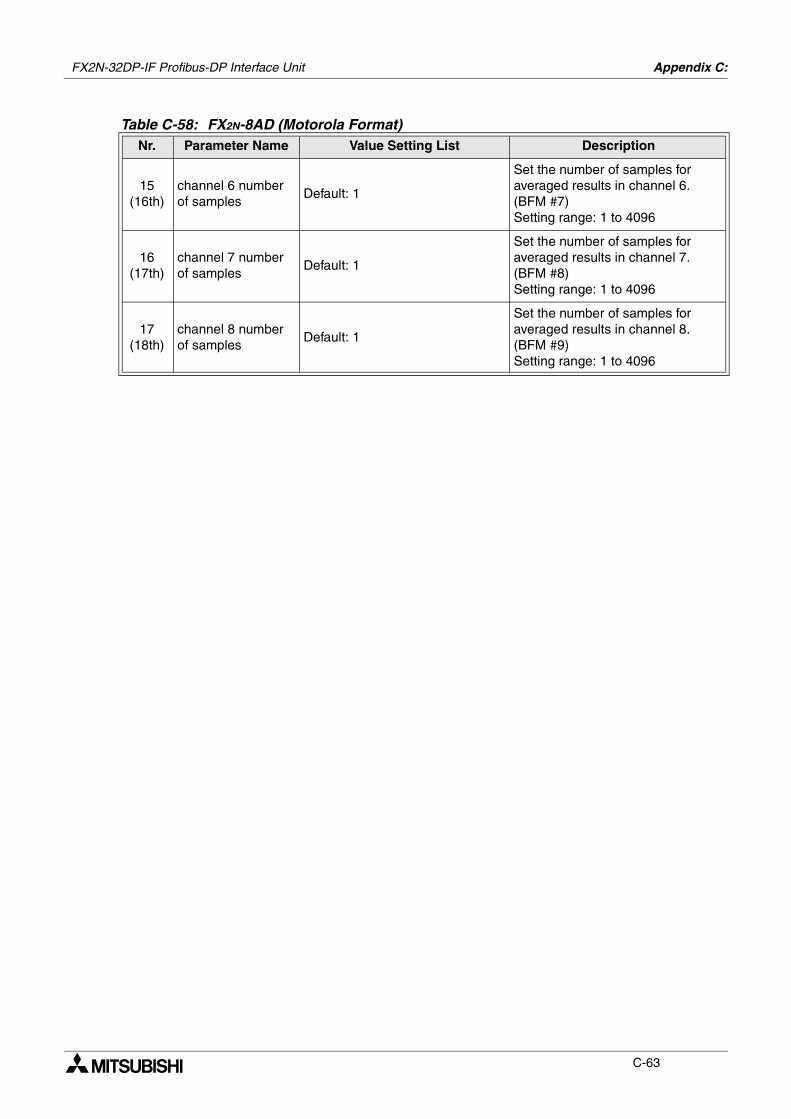
FX2N-32DP-IF Profibus-DP Interface Unit Appendix C:
C-63
15(16th)
channel 6 number of samples
Default: 1
Set the number of samples for averaged results in channel 6. (BFM #7)Setting range: 1 to 4096
16(17th)
channel 7 number of samples
Default: 1
Set the number of samples for averaged results in channel 7. (BFM #8)Setting range: 1 to 4096
17(18th)
channel 8 number of samples
Default: 1
Set the number of samples for averaged results in channel 8. (BFM #9)Setting range: 1 to 4096
Table C-58: FX2N-8AD (Motorola Format)Nr. Parameter Name Value Setting List Description
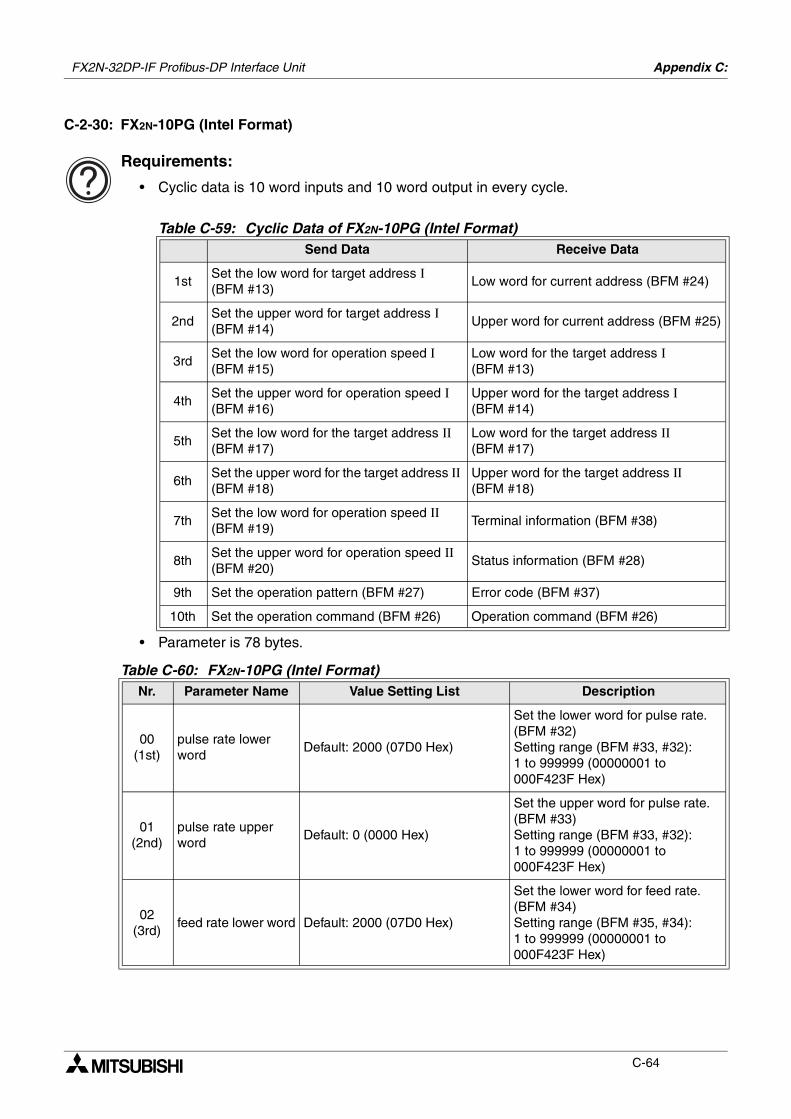
FX2N-32DP-IF Profibus-DP Interface Unit Appendix C:
C-64
C-2-30: FX2N-10PG (Intel Format)
Requirements:
• Cyclic data is 10 word inputs and 10 word output in every cycle.
• Parameter is 78 bytes.
Table C-59: Cyclic Data of FX2N-10PG (Intel Format)Send Data Receive Data
1stSet the low word for target address Ι (BFM #13)
Low word for current address (BFM #24)
2ndSet the upper word for target address Ι (BFM #14)
Upper word for current address (BFM #25)
3rdSet the low word for operation speed Ι (BFM #15)
Low word for the target address Ι (BFM #13)
4thSet the upper word for operation speed Ι (BFM #16)
Upper word for the target address Ι (BFM #14)
5thSet the low word for the target address ΙΙ (BFM #17)
Low word for the target address ΙΙ (BFM #17)
6thSet the upper word for the target address ΙΙ (BFM #18)
Upper word for the target address ΙΙ (BFM #18)
7thSet the low word for operation speed ΙΙ (BFM #19)
Terminal information (BFM #38)
8thSet the upper word for operation speed ΙΙ (BFM #20)
Status information (BFM #28)
9th Set the operation pattern (BFM #27) Error code (BFM #37)
10th Set the operation command (BFM #26) Operation command (BFM #26)
Table C-60: FX2N-10PG (Intel Format)Nr. Parameter Name Value Setting List Description
00(1st)
pulse rate lower word
Default: 2000 (07D0 Hex)
Set the lower word for pulse rate. (BFM #32)Setting range (BFM #33, #32): 1 to 999999 (00000001 to 000F423F Hex)
01(2nd)
pulse rate upper word
Default: 0 (0000 Hex)
Set the upper word for pulse rate. (BFM #33)Setting range (BFM #33, #32): 1 to 999999 (00000001 to 000F423F Hex)
02(3rd)
feed rate lower word Default: 2000 (07D0 Hex)
Set the lower word for feed rate. (BFM #34)Setting range (BFM #35, #34): 1 to 999999 (00000001 to 000F423F Hex)
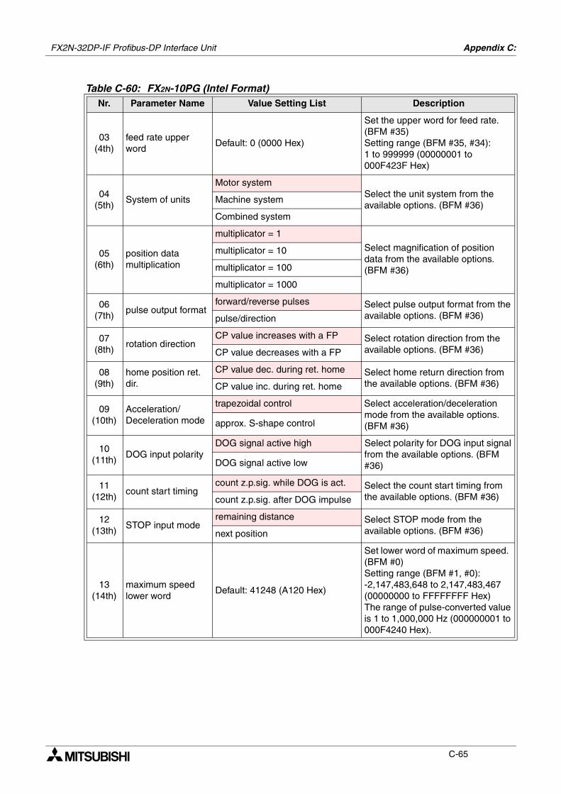
FX2N-32DP-IF Profibus-DP Interface Unit Appendix C:
C-65
03(4th)
feed rate upper word
Default: 0 (0000 Hex)
Set the upper word for feed rate. (BFM #35)Setting range (BFM #35, #34): 1 to 999999 (00000001 to 000F423F Hex)
04(5th)
System of units
Motor systemSelect the unit system from the available options. (BFM #36)
Machine system
Combined system
05(6th)
position data multiplication
multiplicator = 1
Select magnification of position data from the available options. (BFM #36)
multiplicator = 10
multiplicator = 100
multiplicator = 1000
06(7th)
pulse output formatforward/reverse pulses Select pulse output format from the
available options. (BFM #36)pulse/direction
07(8th)
rotation directionCP value increases with a FP Select rotation direction from the
available options. (BFM #36)CP value decreases with a FP
08(9th)
home position ret. dir.
CP value dec. during ret. home Select home return direction from the available options. (BFM #36)CP value inc. during ret. home
09(10th)
Acceleration/Deceleration mode
trapezoidal control Select acceleration/deceleration mode from the available options. (BFM #36)approx. S-shape control
10(11th)
DOG input polarityDOG signal active high Select polarity for DOG input signal
from the available options. (BFM #36)DOG signal active low
11(12th)
count start timingcount z.p.sig. while DOG is act. Select the count start timing from
the available options. (BFM #36)count z.p.sig. after DOG impulse
12(13th)
STOP input moderemaining distance Select STOP mode from the
available options. (BFM #36)next position
13(14th)
maximum speed lower word
Default: 41248 (A120 Hex)
Set lower word of maximum speed. (BFM #0)Setting range (BFM #1, #0): -2,147,483,648 to 2,147,483,467 (00000000 to FFFFFFFF Hex) The range of pulse-converted value is 1 to 1,000,000 Hz (000000001 to 000F4240 Hex).
Table C-60: FX2N-10PG (Intel Format)Nr. Parameter Name Value Setting List Description
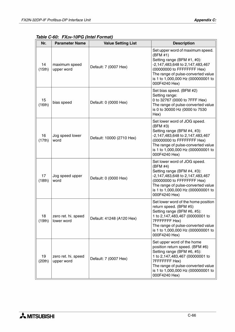
FX2N-32DP-IF Profibus-DP Interface Unit Appendix C:
C-66
14(15th)
maximum speed upper word
Default: 7 (0007 Hex)
Set upper word of maximum speed. (BFM #1)Setting range (BFM #1, #0): -2,147,483,648 to 2,147,483,467 (00000000 to FFFFFFFF Hex) The range of pulse-converted value is 1 to 1,000,000 Hz (000000001 to 000F4240 Hex)
15(16th)
bias speed Default: 0 (0000 Hex)
Set bias speed. (BFM #2)Setting range: 0 to 32767 (0000 to 7FFF Hex) The range of pulse-converted value is 0 to 30000 Hz (0000 to 7530 Hex)
16(17th)
Jog speed lower word
Default: 10000 (2710 Hex)
Set lower word of JOG speed. (BFM #3)Setting range (BFM #4, #3): -2,147,483,648 to 2,147,483,467 (00000000 to FFFFFFFF Hex) The range of pulse-converted value is 1 to 1,000,000 Hz (000000001 to 000F4240 Hex)
17(18th)
Jog speed upper word
Default: 0 (0000 Hex)
Set lower word of JOG speed. (BFM #4)Setting range (BFM #4, #3): -2,147,483,648 to 2,147,483,467 (00000000 to FFFFFFFF Hex) The range of pulse-converted value is 1 to 1,000,000 Hz (000000001 to 000F4240 Hex)
18(19th)
zero ret. hi. speed lower word
Default: 41248 (A120 Hex)
Set lower word of the home position return speed. (BFM #5)Setting range (BFM #6, #5): 1 to 2,147,483,467 (00000001 to 7FFFFFFF Hex) The range of pulse-converted value is 1 to 1,000,000 Hz (000000001 to 000F4240 Hex)
19(20th)
zero ret. hi. speed upper word
Default: 7 (0007 Hex)
Set upper word of the home position return speed. (BFM #6)Setting range (BFM #6, #5): 1 to 2,147,483,467 (00000001 to 7FFFFFFF Hex) The range of pulse-converted value is 1 to 1,000,000 Hz (000000001 to 000F4240 Hex)
Table C-60: FX2N-10PG (Intel Format)Nr. Parameter Name Value Setting List Description
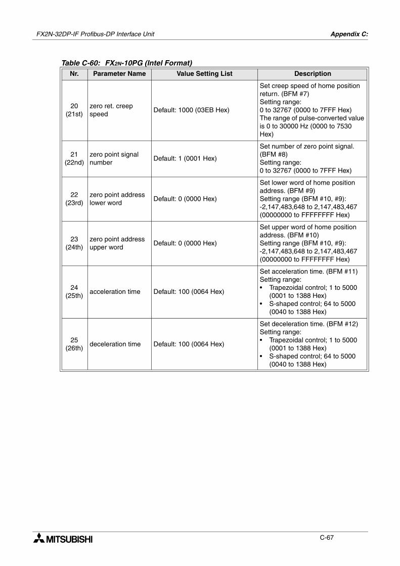
FX2N-32DP-IF Profibus-DP Interface Unit Appendix C:
C-67
20(21st)
zero ret. creep speed
Default: 1000 (03EB Hex)
Set creep speed of home position return. (BFM #7)Setting range: 0 to 32767 (0000 to 7FFF Hex) The range of pulse-converted value is 0 to 30000 Hz (0000 to 7530 Hex)
21(22nd)
zero point signal number
Default: 1 (0001 Hex)
Set number of zero point signal. (BFM #8)Setting range: 0 to 32767 (0000 to 7FFF Hex)
22(23rd)
zero point address lower word
Default: 0 (0000 Hex)
Set lower word of home position address. (BFM #9)Setting range (BFM #10, #9): -2,147,483,648 to 2,147,483,467 (00000000 to FFFFFFFF Hex)
23(24th)
zero point address upper word
Default: 0 (0000 Hex)
Set upper word of home position address. (BFM #10)Setting range (BFM #10, #9): -2,147,483,648 to 2,147,483,467 (00000000 to FFFFFFFF Hex)
24(25th)
acceleration time Default: 100 (0064 Hex)
Set acceleration time. (BFM #11)Setting range:• Trapezoidal control; 1 to 5000
(0001 to 1388 Hex)• S-shaped control; 64 to 5000
(0040 to 1388 Hex)
25(26th)
deceleration time Default: 100 (0064 Hex)
Set deceleration time. (BFM #12)Setting range:• Trapezoidal control; 1 to 5000
(0001 to 1388 Hex)• S-shaped control; 64 to 5000
(0040 to 1388 Hex)
Table C-60: FX2N-10PG (Intel Format)Nr. Parameter Name Value Setting List Description
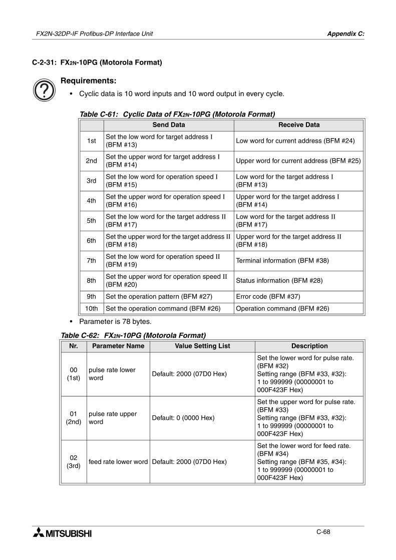
FX2N-32DP-IF Profibus-DP Interface Unit Appendix C:
C-68
C-2-31: FX2N-10PG (Motorola Format)
Requirements:
• Cyclic data is 10 word inputs and 10 word output in every cycle.
• Parameter is 78 bytes.
Table C-61: Cyclic Data of FX2N-10PG (Motorola Format)Send Data Receive Data
1stSet the low word for target address Ι (BFM #13)
Low word for current address (BFM #24)
2ndSet the upper word for target address Ι (BFM #14)
Upper word for current address (BFM #25)
3rdSet the low word for operation speed Ι (BFM #15)
Low word for the target address Ι (BFM #13)
4thSet the upper word for operation speed Ι (BFM #16)
Upper word for the target address Ι (BFM #14)
5thSet the low word for the target address ΙΙ (BFM #17)
Low word for the target address ΙΙ (BFM #17)
6thSet the upper word for the target address ΙΙ (BFM #18)
Upper word for the target address ΙΙ (BFM #18)
7thSet the low word for operation speed ΙΙ (BFM #19)
Terminal information (BFM #38)
8thSet the upper word for operation speed ΙΙ (BFM #20)
Status information (BFM #28)
9th Set the operation pattern (BFM #27) Error code (BFM #37)
10th Set the operation command (BFM #26) Operation command (BFM #26)
Table C-62: FX2N-10PG (Motorola Format)Nr. Parameter Name Value Setting List Description
00(1st)
pulse rate lower word
Default: 2000 (07D0 Hex)
Set the lower word for pulse rate. (BFM #32)Setting range (BFM #33, #32): 1 to 999999 (00000001 to 000F423F Hex)
01(2nd)
pulse rate upper word
Default: 0 (0000 Hex)
Set the upper word for pulse rate. (BFM #33)Setting range (BFM #33, #32): 1 to 999999 (00000001 to 000F423F Hex)
02(3rd)
feed rate lower word Default: 2000 (07D0 Hex)
Set the lower word for feed rate. (BFM #34)Setting range (BFM #35, #34): 1 to 999999 (00000001 to 000F423F Hex)
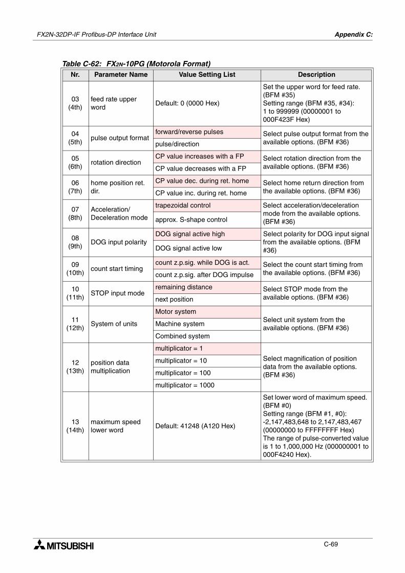
FX2N-32DP-IF Profibus-DP Interface Unit Appendix C:
C-69
03(4th)
feed rate upper word
Default: 0 (0000 Hex)
Set the upper word for feed rate. (BFM #35)Setting range (BFM #35, #34): 1 to 999999 (00000001 to 000F423F Hex)
04(5th)
pulse output formatforward/reverse pulses Select pulse output format from the
available options. (BFM #36)pulse/direction
05(6th)
rotation directionCP value increases with a FP Select rotation direction from the
available options. (BFM #36)CP value decreases with a FP
06(7th)
home position ret. dir.
CP value dec. during ret. home Select home return direction from the available options. (BFM #36)CP value inc. during ret. home
07(8th)
Acceleration/Deceleration mode
trapezoidal control Select acceleration/deceleration mode from the available options. (BFM #36)approx. S-shape control
08(9th)
DOG input polarityDOG signal active high Select polarity for DOG input signal
from the available options. (BFM #36)DOG signal active low
09(10th)
count start timingcount z.p.sig. while DOG is act. Select the count start timing from
the available options. (BFM #36)count z.p.sig. after DOG impulse
10(11th)
STOP input moderemaining distance Select STOP mode from the
available options. (BFM #36)next position
11(12th)
System of units
Motor systemSelect unit system from the available options. (BFM #36)
Machine system
Combined system
12(13th)
position data multiplication
multiplicator = 1
Select magnification of position data from the available options. (BFM #36)
multiplicator = 10
multiplicator = 100
multiplicator = 1000
13(14th)
maximum speed lower word
Default: 41248 (A120 Hex)
Set lower word of maximum speed. (BFM #0)Setting range (BFM #1, #0): -2,147,483,648 to 2,147,483,467 (00000000 to FFFFFFFF Hex) The range of pulse-converted value is 1 to 1,000,000 Hz (000000001 to 000F4240 Hex).
Table C-62: FX2N-10PG (Motorola Format)Nr. Parameter Name Value Setting List Description
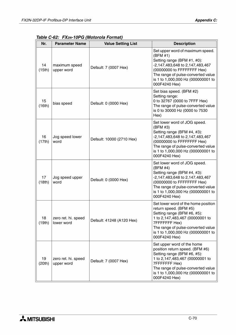
FX2N-32DP-IF Profibus-DP Interface Unit Appendix C:
C-70
14(15th)
maximum speed upper word
Default: 7 (0007 Hex)
Set upper word of maximum speed. (BFM #1)Setting range (BFM #1, #0): -2,147,483,648 to 2,147,483,467 (00000000 to FFFFFFFF Hex) The range of pulse-converted value is 1 to 1,000,000 Hz (000000001 to 000F4240 Hex)
15(16th)
bias speed Default: 0 (0000 Hex)
Set bias speed. (BFM #2)Setting range: 0 to 32767 (0000 to 7FFF Hex) The range of pulse-converted value is 0 to 30000 Hz (0000 to 7530 Hex)
16(17th)
Jog speed lower word
Default: 10000 (2710 Hex)
Set lower word of JOG speed. (BFM #3)Setting range (BFM #4, #3): -2,147,483,648 to 2,147,483,467 (00000000 to FFFFFFFF Hex) The range of pulse-converted value is 1 to 1,000,000 Hz (000000001 to 000F4240 Hex)
17(18th)
Jog speed upper word
Default: 0 (0000 Hex)
Set lower word of JOG speed. (BFM #4)Setting range (BFM #4, #3): -2,147,483,648 to 2,147,483,467 (00000000 to FFFFFFFF Hex) The range of pulse-converted value is 1 to 1,000,000 Hz (000000001 to 000F4240 Hex)
18(19th)
zero ret. hi. speed lower word
Default: 41248 (A120 Hex)
Set lower word of the home position return speed. (BFM #5)Setting range (BFM #6, #5): 1 to 2,147,483,467 (00000001 to 7FFFFFFF Hex) The range of pulse-converted value is 1 to 1,000,000 Hz (000000001 to 000F4240 Hex)
19(20th)
zero ret. hi. speed upper word
Default: 7 (0007 Hex)
Set upper word of the home position return speed. (BFM #6)Setting range (BFM #6, #5): 1 to 2,147,483,467 (00000001 to 7FFFFFFF Hex) The range of pulse-converted value is 1 to 1,000,000 Hz (000000001 to 000F4240 Hex)
Table C-62: FX2N-10PG (Motorola Format)Nr. Parameter Name Value Setting List Description

FX2N-32DP-IF Profibus-DP Interface Unit Appendix C:
C-71
20(21st)
zero ret. creep speed
Default: 1000 (03EB Hex)
Set creep speed of home position return. (BFM #7)Setting range: 0 to 32767 (0000 to 7FFF Hex) The range of pulse-converted value is 0 to 30000 Hz (0000 to 7530 Hex)
21(22nd)
zero point signal number
Default: 1 (0001 Hex)
Set number of zero point signal. (BFM #8)Setting range: 0 to 32767 (0000 to 7FFF Hex)
22(23rd)
zero point address lower word
Default: 0 (0000 Hex)
Set lower word of home position address. (BFM #9)Setting range (BFM #10, #9): -2,147,483,648 to 2,147,483,467 (00000000 to FFFFFFFF Hex)
23(24th)
zero point address upper word
Default: 0 (0000 Hex)
Set upper word of home position address. (BFM #10)Setting range (BFM #10, #9): -2,147,483,648 to 2,147,483,467 (00000000 to FFFFFFFF Hex)
24(25th)
acceleration time Default: 100 (0064 Hex)
Set acceleration time. (BFM #11)Setting range:• Trapezoidal control; 1 to 5000
(0001 to 1388 Hex)• S-shaped control; 64 to 5000
(0040 to 1388 Hex)
25(26th)
deceleration time Default: 100 (0064 Hex)
Set deceleration time. (BFM #12)Setting range:• Trapezoidal control; 1 to 5000
(0001 to 1388 Hex)• S-shaped control; 64 to 5000
(0040 to 1388 Hex)
Table C-62: FX2N-10PG (Motorola Format)Nr. Parameter Name Value Setting List Description
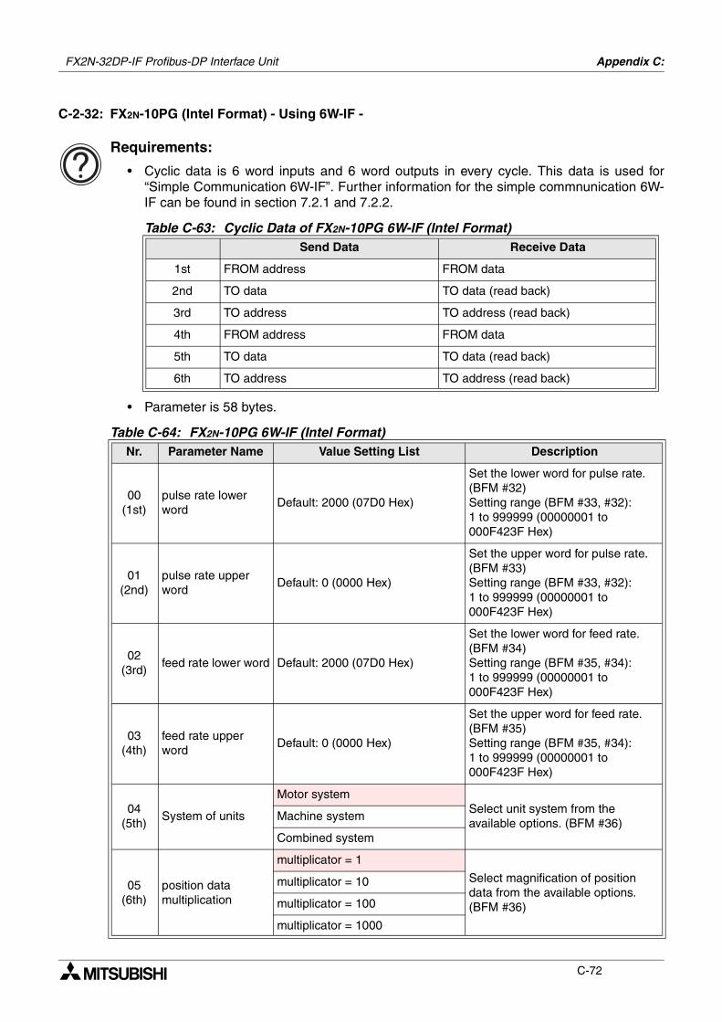
FX2N-32DP-IF Profibus-DP Interface Unit Appendix C:
C-72
C-2-32: FX2N-10PG (Intel Format) - Using 6W-IF -
Requirements:
• Cyclic data is 6 word inputs and 6 word outputs in every cycle. This data is used for“Simple Communication 6W-IF”. Further information for the simple commnunication 6W-IF can be found in section 7.2.1 and 7.2.2.
• Parameter is 58 bytes.
Table C-63: Cyclic Data of FX2N-10PG 6W-IF (Intel Format)Send Data Receive Data
1st FROM address FROM data
2nd TO data TO data (read back)
3rd TO address TO address (read back)
4th FROM address FROM data
5th TO data TO data (read back)
6th TO address TO address (read back)
Table C-64: FX2N-10PG 6W-IF (Intel Format)Nr. Parameter Name Value Setting List Description
00(1st)
pulse rate lower word
Default: 2000 (07D0 Hex)
Set the lower word for pulse rate. (BFM #32)Setting range (BFM #33, #32): 1 to 999999 (00000001 to 000F423F Hex)
01(2nd)
pulse rate upper word
Default: 0 (0000 Hex)
Set the upper word for pulse rate. (BFM #33)Setting range (BFM #33, #32): 1 to 999999 (00000001 to 000F423F Hex)
02(3rd)
feed rate lower word Default: 2000 (07D0 Hex)
Set the lower word for feed rate. (BFM #34)Setting range (BFM #35, #34): 1 to 999999 (00000001 to 000F423F Hex)
03(4th)
feed rate upper word
Default: 0 (0000 Hex)
Set the upper word for feed rate. (BFM #35)Setting range (BFM #35, #34): 1 to 999999 (00000001 to 000F423F Hex)
04(5th)
System of units
Motor systemSelect unit system from the available options. (BFM #36)
Machine system
Combined system
05(6th)
position data multiplication
multiplicator = 1
Select magnification of position data from the available options. (BFM #36)
multiplicator = 10
multiplicator = 100
multiplicator = 1000
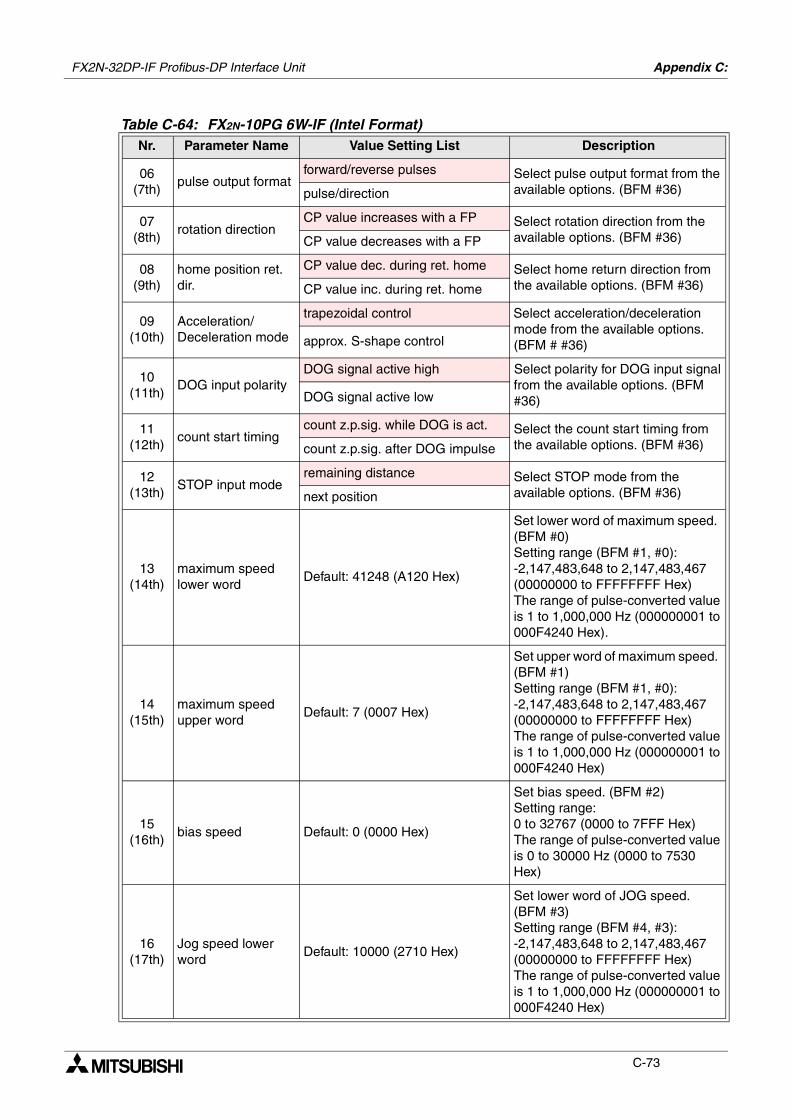
FX2N-32DP-IF Profibus-DP Interface Unit Appendix C:
C-73
06(7th)
pulse output formatforward/reverse pulses Select pulse output format from the
available options. (BFM #36)pulse/direction
07(8th)
rotation directionCP value increases with a FP Select rotation direction from the
available options. (BFM #36)CP value decreases with a FP
08(9th)
home position ret. dir.
CP value dec. during ret. home Select home return direction from the available options. (BFM #36)CP value inc. during ret. home
09(10th)
Acceleration/Deceleration mode
trapezoidal control Select acceleration/deceleration mode from the available options. (BFM # #36)approx. S-shape control
10(11th)
DOG input polarityDOG signal active high Select polarity for DOG input signal
from the available options. (BFM #36)DOG signal active low
11(12th)
count start timingcount z.p.sig. while DOG is act. Select the count start timing from
the available options. (BFM #36)count z.p.sig. after DOG impulse
12(13th)
STOP input moderemaining distance Select STOP mode from the
available options. (BFM #36)next position
13(14th)
maximum speed lower word
Default: 41248 (A120 Hex)
Set lower word of maximum speed. (BFM #0)Setting range (BFM #1, #0): -2,147,483,648 to 2,147,483,467 (00000000 to FFFFFFFF Hex) The range of pulse-converted value is 1 to 1,000,000 Hz (000000001 to 000F4240 Hex).
14(15th)
maximum speed upper word
Default: 7 (0007 Hex)
Set upper word of maximum speed. (BFM #1)Setting range (BFM #1, #0): -2,147,483,648 to 2,147,483,467 (00000000 to FFFFFFFF Hex) The range of pulse-converted value is 1 to 1,000,000 Hz (000000001 to 000F4240 Hex)
15(16th)
bias speed Default: 0 (0000 Hex)
Set bias speed. (BFM #2)Setting range: 0 to 32767 (0000 to 7FFF Hex) The range of pulse-converted value is 0 to 30000 Hz (0000 to 7530 Hex)
16(17th)
Jog speed lower word
Default: 10000 (2710 Hex)
Set lower word of JOG speed. (BFM #3)Setting range (BFM #4, #3): -2,147,483,648 to 2,147,483,467 (00000000 to FFFFFFFF Hex) The range of pulse-converted value is 1 to 1,000,000 Hz (000000001 to 000F4240 Hex)
Table C-64: FX2N-10PG 6W-IF (Intel Format)Nr. Parameter Name Value Setting List Description
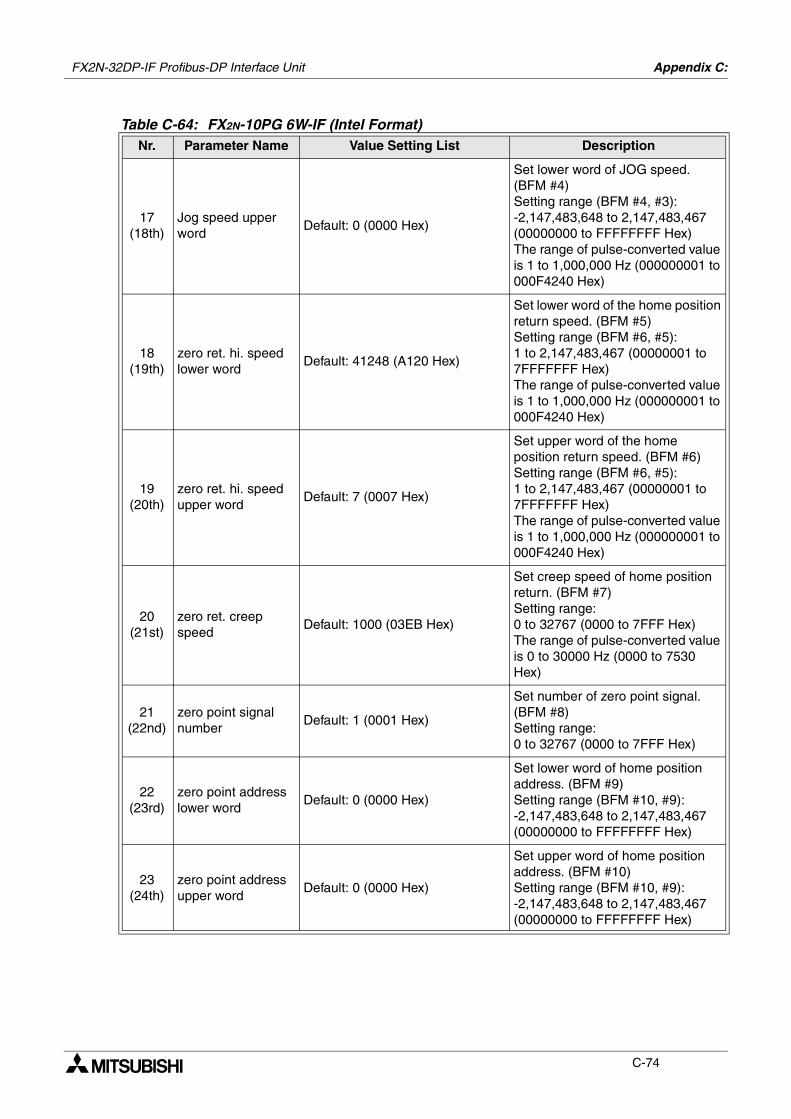
FX2N-32DP-IF Profibus-DP Interface Unit Appendix C:
C-74
17(18th)
Jog speed upper word
Default: 0 (0000 Hex)
Set lower word of JOG speed. (BFM #4)Setting range (BFM #4, #3): -2,147,483,648 to 2,147,483,467 (00000000 to FFFFFFFF Hex) The range of pulse-converted value is 1 to 1,000,000 Hz (000000001 to 000F4240 Hex)
18(19th)
zero ret. hi. speed lower word
Default: 41248 (A120 Hex)
Set lower word of the home position return speed. (BFM #5)Setting range (BFM #6, #5): 1 to 2,147,483,467 (00000001 to 7FFFFFFF Hex) The range of pulse-converted value is 1 to 1,000,000 Hz (000000001 to 000F4240 Hex)
19(20th)
zero ret. hi. speed upper word
Default: 7 (0007 Hex)
Set upper word of the home position return speed. (BFM #6)Setting range (BFM #6, #5): 1 to 2,147,483,467 (00000001 to 7FFFFFFF Hex) The range of pulse-converted value is 1 to 1,000,000 Hz (000000001 to 000F4240 Hex)
20(21st)
zero ret. creep speed
Default: 1000 (03EB Hex)
Set creep speed of home position return. (BFM #7)Setting range: 0 to 32767 (0000 to 7FFF Hex) The range of pulse-converted value is 0 to 30000 Hz (0000 to 7530 Hex)
21(22nd)
zero point signal number
Default: 1 (0001 Hex)
Set number of zero point signal. (BFM #8)Setting range: 0 to 32767 (0000 to 7FFF Hex)
22(23rd)
zero point address lower word
Default: 0 (0000 Hex)
Set lower word of home position address. (BFM #9)Setting range (BFM #10, #9): -2,147,483,648 to 2,147,483,467 (00000000 to FFFFFFFF Hex)
23(24th)
zero point address upper word
Default: 0 (0000 Hex)
Set upper word of home position address. (BFM #10)Setting range (BFM #10, #9): -2,147,483,648 to 2,147,483,467 (00000000 to FFFFFFFF Hex)
Table C-64: FX2N-10PG 6W-IF (Intel Format)Nr. Parameter Name Value Setting List Description
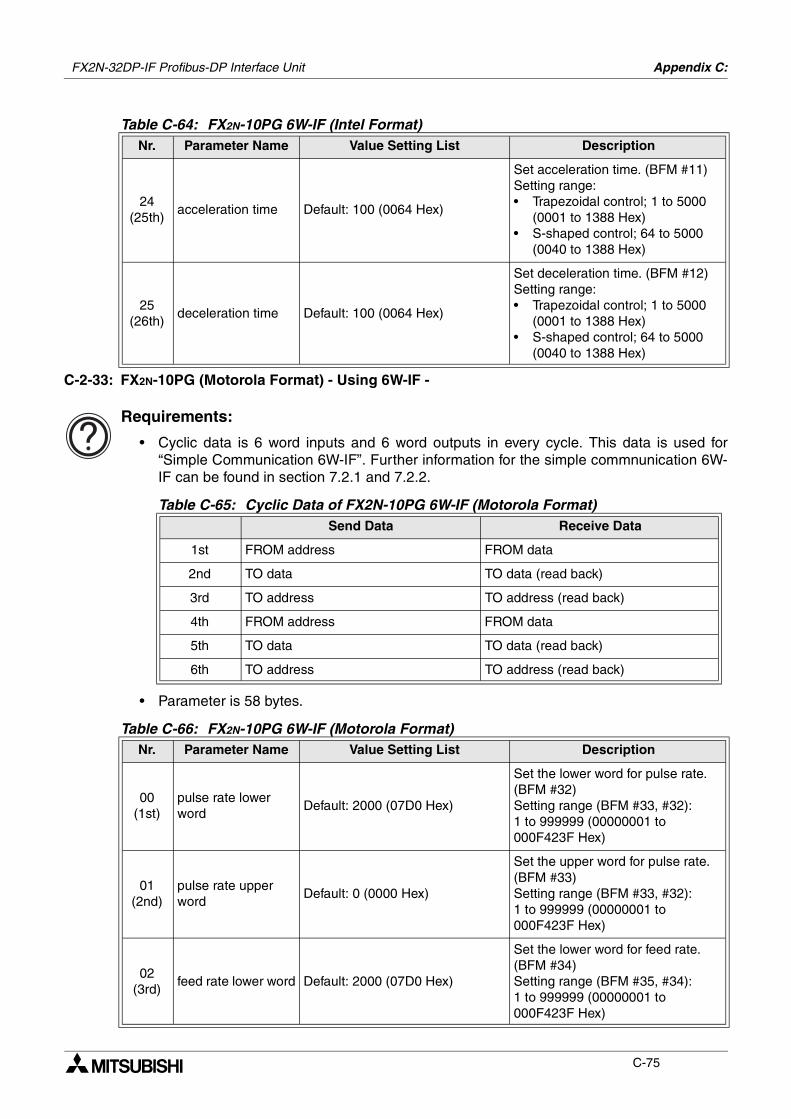
FX2N-32DP-IF Profibus-DP Interface Unit Appendix C:
C-75
C-2-33: FX2N-10PG (Motorola Format) - Using 6W-IF -
Requirements:
• Cyclic data is 6 word inputs and 6 word outputs in every cycle. This data is used for“Simple Communication 6W-IF”. Further information for the simple commnunication 6W-IF can be found in section 7.2.1 and 7.2.2.
• Parameter is 58 bytes.
24(25th)
acceleration time Default: 100 (0064 Hex)
Set acceleration time. (BFM #11)Setting range:• Trapezoidal control; 1 to 5000
(0001 to 1388 Hex)• S-shaped control; 64 to 5000
(0040 to 1388 Hex)
25(26th)
deceleration time Default: 100 (0064 Hex)
Set deceleration time. (BFM #12)Setting range:• Trapezoidal control; 1 to 5000
(0001 to 1388 Hex)• S-shaped control; 64 to 5000
(0040 to 1388 Hex)
Table C-65: Cyclic Data of FX2N-10PG 6W-IF (Motorola Format)Send Data Receive Data
1st FROM address FROM data
2nd TO data TO data (read back)
3rd TO address TO address (read back)
4th FROM address FROM data
5th TO data TO data (read back)
6th TO address TO address (read back)
Table C-66: FX2N-10PG 6W-IF (Motorola Format)Nr. Parameter Name Value Setting List Description
00(1st)
pulse rate lower word
Default: 2000 (07D0 Hex)
Set the lower word for pulse rate. (BFM #32)Setting range (BFM #33, #32): 1 to 999999 (00000001 to 000F423F Hex)
01(2nd)
pulse rate upper word
Default: 0 (0000 Hex)
Set the upper word for pulse rate. (BFM #33)Setting range (BFM #33, #32): 1 to 999999 (00000001 to 000F423F Hex)
02(3rd)
feed rate lower word Default: 2000 (07D0 Hex)
Set the lower word for feed rate. (BFM #34)Setting range (BFM #35, #34): 1 to 999999 (00000001 to 000F423F Hex)
Table C-64: FX2N-10PG 6W-IF (Intel Format)Nr. Parameter Name Value Setting List Description
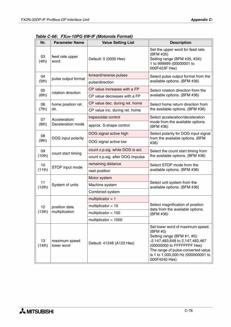
FX2N-32DP-IF Profibus-DP Interface Unit Appendix C:
C-76
03(4th)
feed rate upper word
Default: 0 (0000 Hex)
Set the upper word for feed rate. (BFM #35)Setting range (BFM #35, #34): 1 to 999999 (00000001 to 000F423F Hex)
04(5th)
pulse output formatforward/reverse pulses Select pulse output format from the
available options. (BFM #36)pulse/direction
05(6th)
rotation directionCP value increases with a FP Select rotation direction from the
available options. (BFM #36)CP value decreases with a FP
06(7th)
home position ret. dir.
CP value dec. during ret. home Select home return direction from the available options. (BFM #36)CP value inc. during ret. home
07(8th)
Acceleration/Deceleration mode
trapezoidal control Select acceleration/deceleration mode from the available options. (BFM #36)approx. S-shape control
08(9th)
DOG input polarityDOG signal active high Select polarity for DOG input signal
from the available options. (BFM #36)DOG signal active low
09(10th)
count start timingcount z.p.sig. while DOG is act. Select the count start timing from
the available options. (BFM #36)count z.p.sig. after DOG impulse
10(11th)
STOP input moderemaining distance Select STOP mode from the
available options. (BFM #36)next position
11(12th)
System of units
Motor systemSelect unit system from the available options. (BFM #36)
Machine system
Combined system
12(13th)
position data multiplication
multiplicator = 1
Select magnification of position data from the available options. (BFM #36)
multiplicator = 10
multiplicator = 100
multiplicator = 1000
13(14th)
maximum speed lower word
Default: 41248 (A120 Hex)
Set lower word of maximum speed. (BFM #0)Setting range (BFM #1, #0): -2,147,483,648 to 2,147,483,467 (00000000 to FFFFFFFF Hex) The range of pulse-converted value is 1 to 1,000,000 Hz (000000001 to 000F4240 Hex).
Table C-66: FX2N-10PG 6W-IF (Motorola Format)Nr. Parameter Name Value Setting List Description
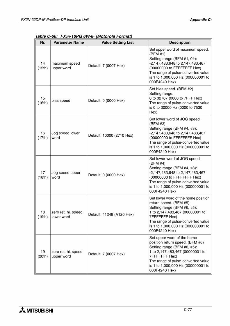
FX2N-32DP-IF Profibus-DP Interface Unit Appendix C:
C-77
14(15th)
maximum speed upper word
Default: 7 (0007 Hex)
Set upper word of maximum speed. (BFM #1)Setting range (BFM #1, 0#): -2,147,483,648 to 2,147,483,467 (00000000 to FFFFFFFF Hex) The range of pulse-converted value is 1 to 1,000,000 Hz (000000001 to 000F4240 Hex)
15(16th)
bias speed Default: 0 (0000 Hex)
Set bias speed. (BFM #2)Setting range: 0 to 32767 (0000 to 7FFF Hex) The range of pulse-converted value is 0 to 30000 Hz (0000 to 7530 Hex)
16(17th)
Jog speed lower word
Default: 10000 (2710 Hex)
Set lower word of JOG speed. (BFM #3)Setting range (BFM #4, #3): -2,147,483,648 to 2,147,483,467 (00000000 to FFFFFFFF Hex) The range of pulse-converted value is 1 to 1,000,000 Hz (000000001 to 000F4240 Hex)
17(18th)
Jog speed upper word
Default: 0 (0000 Hex)
Set lower word of JOG speed. (BFM #4)Setting range (BFM #4, #3): -2,147,483,648 to 2,147,483,467 (00000000 to FFFFFFFF Hex) The range of pulse-converted value is 1 to 1,000,000 Hz (000000001 to 000F4240 Hex)
18(19th)
zero ret. hi. speed lower word
Default: 41248 (A120 Hex)
Set lower word of the home position return speed. (BFM #5)Setting range (BFM #6, #5): 1 to 2,147,483,467 (00000001 to 7FFFFFFF Hex) The range of pulse-converted value is 1 to 1,000,000 Hz (000000001 to 000F4240 Hex)
19(20th)
zero ret. hi. speed upper word
Default: 7 (0007 Hex)
Set upper word of the home position return speed. (BFM #6)Setting range (BFM #6, #5): 1 to 2,147,483,467 (00000001 to 7FFFFFFF Hex) The range of pulse-converted value is 1 to 1,000,000 Hz (000000001 to 000F4240 Hex)
Table C-66: FX2N-10PG 6W-IF (Motorola Format)Nr. Parameter Name Value Setting List Description
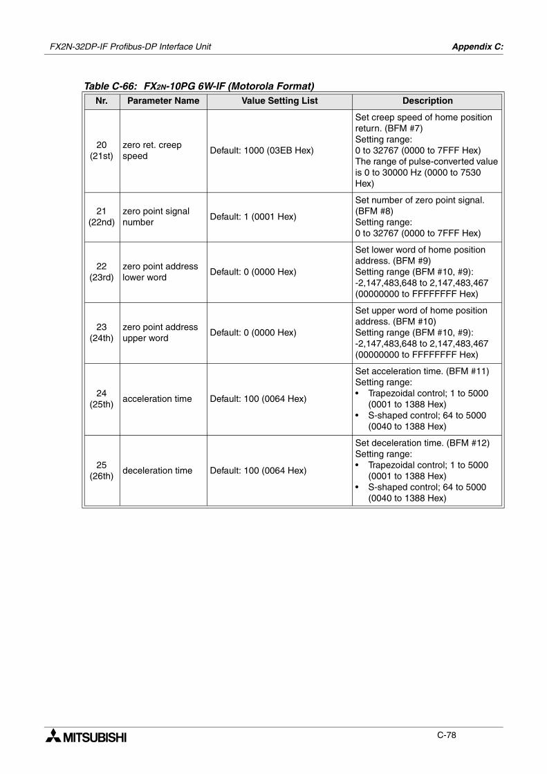
FX2N-32DP-IF Profibus-DP Interface Unit Appendix C:
C-78
20(21st)
zero ret. creep speed
Default: 1000 (03EB Hex)
Set creep speed of home position return. (BFM #7)Setting range: 0 to 32767 (0000 to 7FFF Hex) The range of pulse-converted value is 0 to 30000 Hz (0000 to 7530 Hex)
21(22nd)
zero point signal number
Default: 1 (0001 Hex)
Set number of zero point signal. (BFM #8)Setting range: 0 to 32767 (0000 to 7FFF Hex)
22(23rd)
zero point address lower word
Default: 0 (0000 Hex)
Set lower word of home position address. (BFM #9)Setting range (BFM #10, #9): -2,147,483,648 to 2,147,483,467 (00000000 to FFFFFFFF Hex)
23(24th)
zero point address upper word
Default: 0 (0000 Hex)
Set upper word of home position address. (BFM #10)Setting range (BFM #10, #9): -2,147,483,648 to 2,147,483,467 (00000000 to FFFFFFFF Hex)
24(25th)
acceleration time Default: 100 (0064 Hex)
Set acceleration time. (BFM #11)Setting range:• Trapezoidal control; 1 to 5000
(0001 to 1388 Hex)• S-shaped control; 64 to 5000
(0040 to 1388 Hex)
25(26th)
deceleration time Default: 100 (0064 Hex)
Set deceleration time. (BFM #12)Setting range:• Trapezoidal control; 1 to 5000
(0001 to 1388 Hex)• S-shaped control; 64 to 5000
(0040 to 1388 Hex)
Table C-66: FX2N-10PG 6W-IF (Motorola Format)Nr. Parameter Name Value Setting List Description
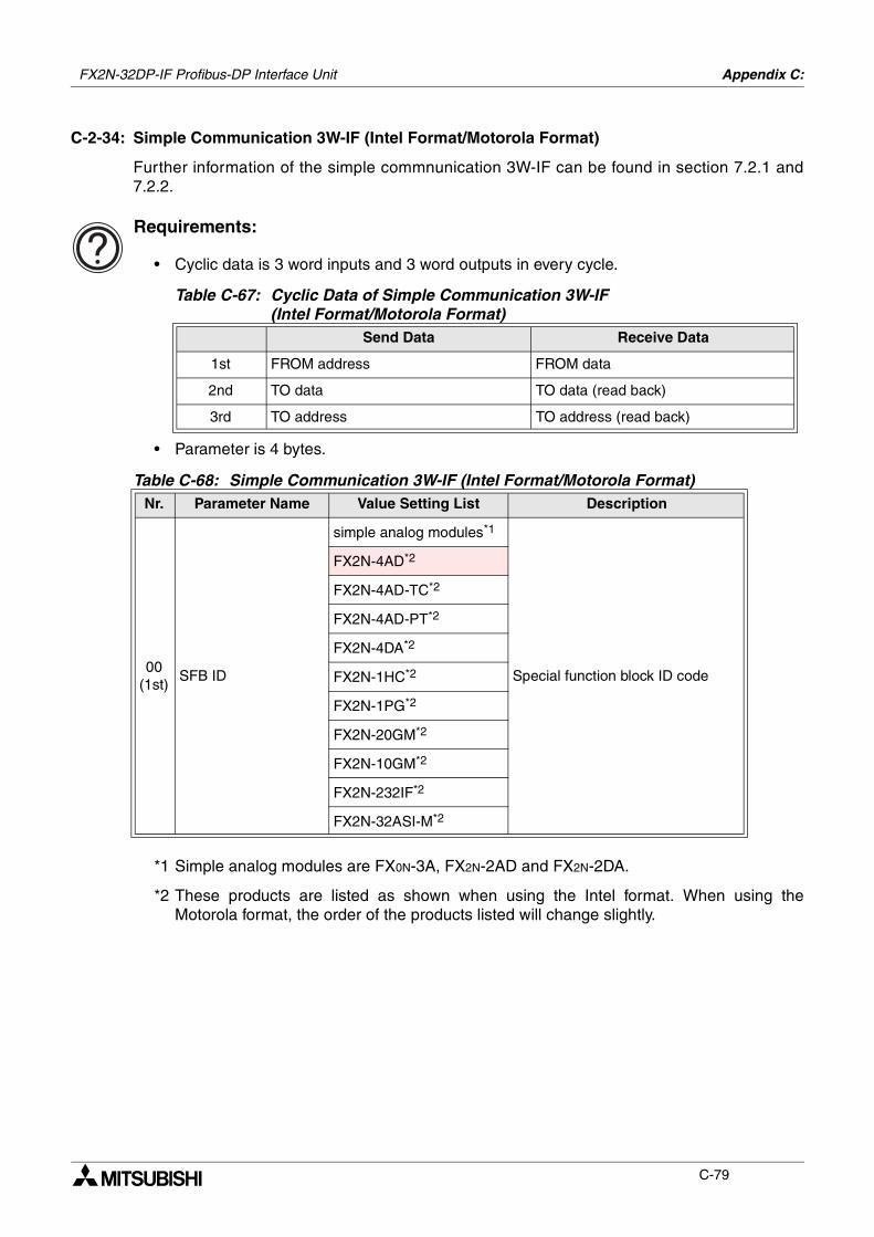
FX2N-32DP-IF Profibus-DP Interface Unit Appendix C:
C-79
C-2-34: Simple Communication 3W-IF (Intel Format/Motorola Format)
Further information of the simple commnunication 3W-IF can be found in section 7.2.1 and7.2.2.
Requirements:
• Cyclic data is 3 word inputs and 3 word outputs in every cycle.
• Parameter is 4 bytes.
*1 Simple analog modules are FX0N-3A, FX2N-2AD and FX2N-2DA.
*2 These products are listed as shown when using the Intel format. When using theMotorola format, the order of the products listed will change slightly.
Table C-67: Cyclic Data of Simple Communication 3W-IF (Intel Format/Motorola Format)
Send Data Receive Data
1st FROM address FROM data
2nd TO data TO data (read back)
3rd TO address TO address (read back)
Table C-68: Simple Communication 3W-IF (Intel Format/Motorola Format)Nr. Parameter Name Value Setting List Description
00(1st)
SFB ID
simple analog modules*1
Special function block ID code
FX2N-4AD*2
FX2N-4AD-TC*2
FX2N-4AD-PT*2
FX2N-4DA*2
FX2N-1HC*2
FX2N-1PG*2
FX2N-20GM*2
FX2N-10GM*2
FX2N-232IF*2
FX2N-32ASI-M*2
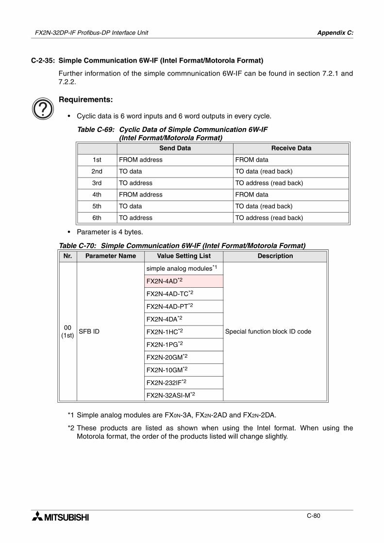
FX2N-32DP-IF Profibus-DP Interface Unit Appendix C:
C-80
C-2-35: Simple Communication 6W-IF (Intel Format/Motorola Format)
Further information of the simple commnunication 6W-IF can be found in section 7.2.1 and7.2.2.
Requirements:
• Cyclic data is 6 word inputs and 6 word outputs in every cycle.
• Parameter is 4 bytes.
*1 Simple analog modules are FX0N-3A, FX2N-2AD and FX2N-2DA.
*2 These products are listed as shown when using the Intel format. When using theMotorola format, the order of the products listed will change slightly.
Table C-69: Cyclic Data of Simple Communication 6W-IF (Intel Format/Motorola Format)
Send Data Receive Data
1st FROM address FROM data
2nd TO data TO data (read back)
3rd TO address TO address (read back)
4th FROM address FROM data
5th TO data TO data (read back)
6th TO address TO address (read back)
Table C-70: Simple Communication 6W-IF (Intel Format/Motorola Format)Nr. Parameter Name Value Setting List Description
00(1st)
SFB ID
simple analog modules*1
Special function block ID code
FX2N-4AD*2
FX2N-4AD-TC*2
FX2N-4AD-PT*2
FX2N-4DA*2
FX2N-1HC*2
FX2N-1PG*2
FX2N-20GM*2
FX2N-10GM*2
FX2N-232IF*2
FX2N-32ASI-M*2
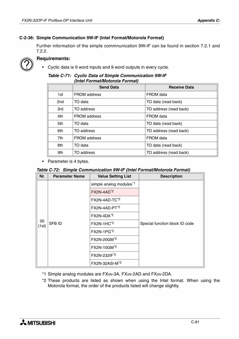
FX2N-32DP-IF Profibus-DP Interface Unit Appendix C:
C-81
C-2-36: Simple Communication 9W-IF (Intel Format/Motorola Format)
Further information of the simple commnunication 9W-IF can be found in section 7.2.1 and7.2.2.
Requirements:
• Cyclic data is 9 word inputs and 9 word outputs in every cycle.
• Parameter is 4 bytes.
*1 Simple analog modules are FX0N-3A, FX2N-2AD and FX2N-2DA.
*2 These products are listed as shown when using the Intel format. When using theMotorola format, the order of the products listed will change slightly.
Table C-71: Cyclic Data of Simple Communication 9W-IF (Intel Format/Motorola Format)
Send Data Receive Data
1st FROM address FROM data
2nd TO data TO data (read back)
3rd TO address TO address (read back)
4th FROM address FROM data
5th TO data TO data (read back)
6th TO address TO address (read back)
7th FROM address FROM data
8th TO data TO data (read back)
9th TO address TO address (read back)
Table C-72: Simple Communication 9W-IF (Intel Format/Motorola Format)Nr. Parameter Name Value Setting List Description
00(1st)
SFB ID
simple analog modules*1
Special function block ID code
FX2N-4AD*2
FX2N-4AD-TC*2
FX2N-4AD-PT*2
FX2N-4DA*2
FX2N-1HC*2
FX2N-1PG*2
FX2N-20GM*2
FX2N-10GM*2
FX2N-232IF*2
FX2N-32ASI-M*2
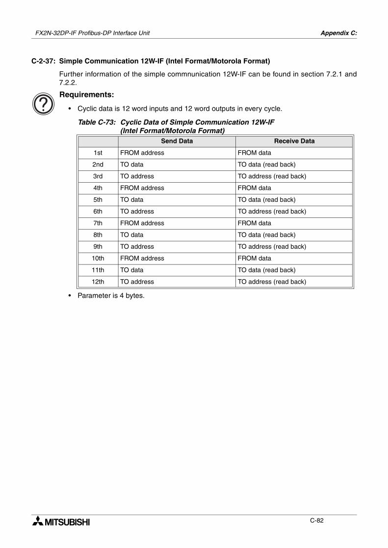
FX2N-32DP-IF Profibus-DP Interface Unit Appendix C:
C-82
C-2-37: Simple Communication 12W-IF (Intel Format/Motorola Format)
Further information of the simple commnunication 12W-IF can be found in section 7.2.1 and7.2.2.
Requirements:
• Cyclic data is 12 word inputs and 12 word outputs in every cycle.
• Parameter is 4 bytes.
Table C-73: Cyclic Data of Simple Communication 12W-IF (Intel Format/Motorola Format)
Send Data Receive Data
1st FROM address FROM data
2nd TO data TO data (read back)
3rd TO address TO address (read back)
4th FROM address FROM data
5th TO data TO data (read back)
6th TO address TO address (read back)
7th FROM address FROM data
8th TO data TO data (read back)
9th TO address TO address (read back)
10th FROM address FROM data
11th TO data TO data (read back)
12th TO address TO address (read back)
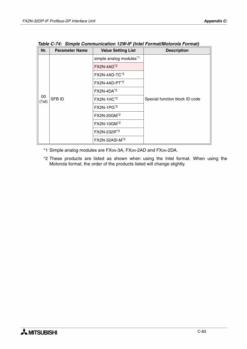
FX2N-32DP-IF Profibus-DP Interface Unit Appendix C:
C-83
*1 Simple analog modules are FX0N-3A, FX2N-2AD and FX2N-2DA.
*2 These products are listed as shown when using the Intel format. When using theMotorola format, the order of the products listed will change slightly.
Table C-74: Simple Communication 12W-IF (Intel Format/Motorola Format)Nr. Parameter Name Value Setting List Description
00(1st)
SFB ID
simple analog modules*1
Special function block ID code
FX2N-4AD*2
FX2N-4AD-TC*2
FX2N-4AD-PT*2
FX2N-4DA*2
FX2N-1HC*2
FX2N-1PG*2
FX2N-20GM*2
FX2N-10GM*2
FX2N-232IF*2
FX2N-32ASI-M*2
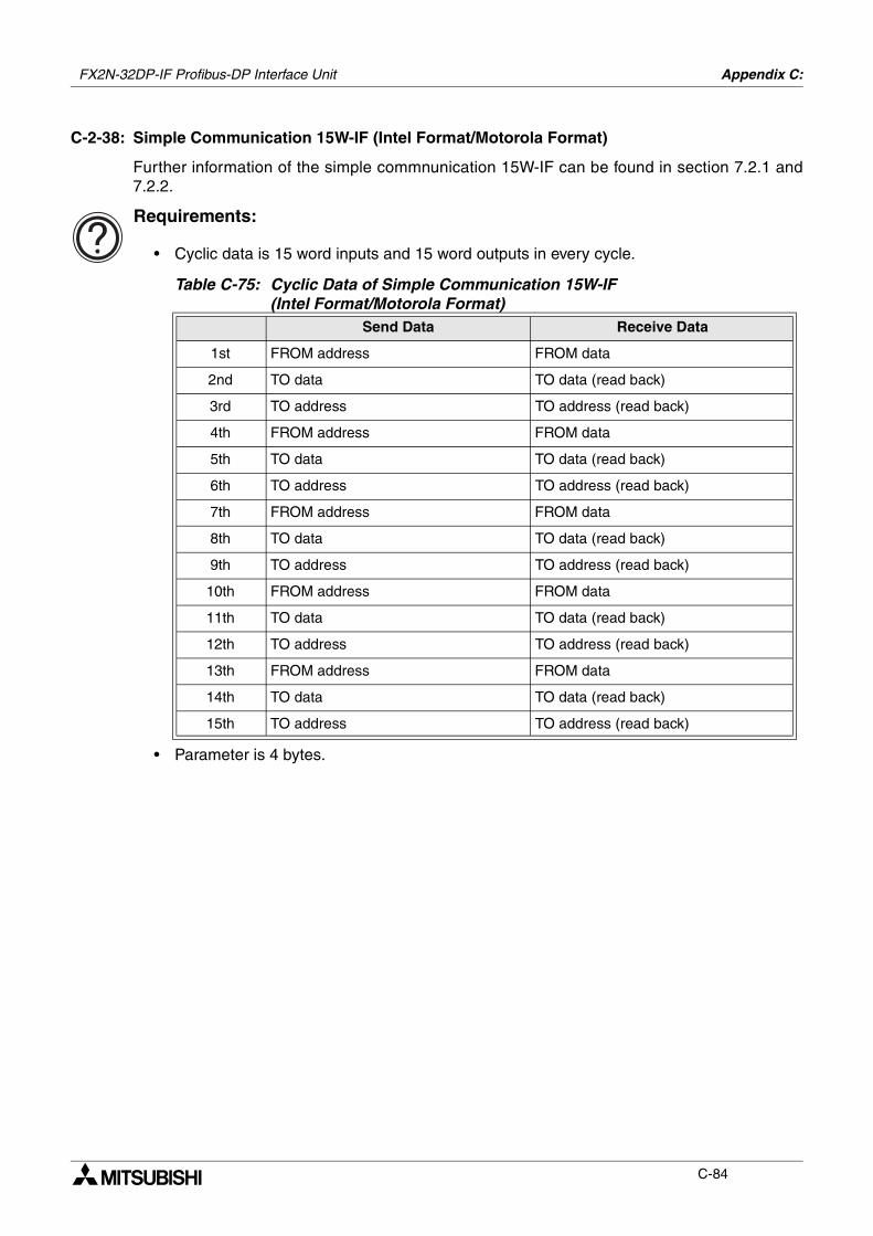
FX2N-32DP-IF Profibus-DP Interface Unit Appendix C:
C-84
C-2-38: Simple Communication 15W-IF (Intel Format/Motorola Format)
Further information of the simple commnunication 15W-IF can be found in section 7.2.1 and7.2.2.
Requirements:
• Cyclic data is 15 word inputs and 15 word outputs in every cycle.
• Parameter is 4 bytes.
Table C-75: Cyclic Data of Simple Communication 15W-IF (Intel Format/Motorola Format)
Send Data Receive Data
1st FROM address FROM data
2nd TO data TO data (read back)
3rd TO address TO address (read back)
4th FROM address FROM data
5th TO data TO data (read back)
6th TO address TO address (read back)
7th FROM address FROM data
8th TO data TO data (read back)
9th TO address TO address (read back)
10th FROM address FROM data
11th TO data TO data (read back)
12th TO address TO address (read back)
13th FROM address FROM data
14th TO data TO data (read back)
15th TO address TO address (read back)
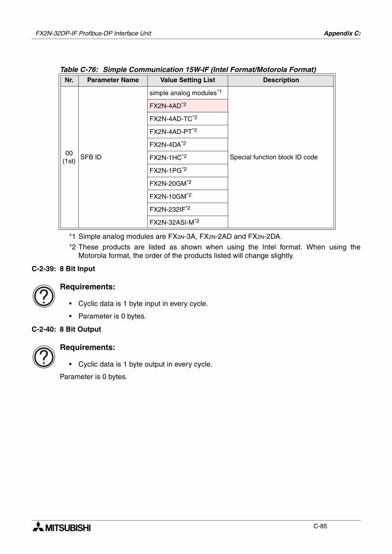
FX2N-32DP-IF Profibus-DP Interface Unit Appendix C:
C-85
*1 Simple analog modules are FX0N-3A, FX2N-2AD and FX2N-2DA.
*2 These products are listed as shown when using the Intel format. When using theMotorola format, the order of the products listed will change slightly.
C-2-39: 8 Bit Input
Requirements:
• Cyclic data is 1 byte input in every cycle.
• Parameter is 0 bytes.
C-2-40: 8 Bit Output
Requirements:
• Cyclic data is 1 byte output in every cycle.
Parameter is 0 bytes.
Table C-76: Simple Communication 15W-IF (Intel Format/Motorola Format)Nr. Parameter Name Value Setting List Description
00(1st)
SFB ID
simple analog modules*1
Special function block ID code
FX2N-4AD*2
FX2N-4AD-TC*2
FX2N-4AD-PT*2
FX2N-4DA*2
FX2N-1HC*2
FX2N-1PG*2
FX2N-20GM*2
FX2N-10GM*2
FX2N-232IF*2
FX2N-32ASI-M*2

FX2N-32DP-IF Profibus-DP Interface Unit Appendix C:
C-86
MEMO
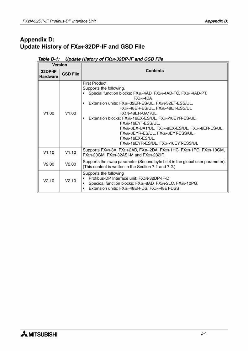
Appendix D:
D-1
Appendix D:Update History of FX2N-32DP-IF and GSD File
Table D-1: Update History of FX2N-32DP-IF and GSD FileVersion
Contents32DP-IF Hardware
GSD File
V1.00 V1.00
First ProductSupports the following.• Special function blocks: FX2N-4AD, FX2N-4AD-TC, FX2N-4AD-PT,
FX2N-4DA• Extension units: FX2N-32ER-ES/UL, FX2N-32ET-ESS/UL,
FX2N-48ER-ES/UL, FX2N-48ET-ESS/ULFX2N-48ER-UA1/UL
• Extension blocks: FX2N-16EX-ES/UL, FX2N-16EYR-ES/UL, FX2N-16EYT-ESS/UL, FX0N-8EX-UA1/UL, FX0N-8EX-ES/UL, FX0N-8ER-ES/UL, FX0N-8EYR-ES/UL, FX0N-8EYT-ESS/UL, FX0N-16EX-ES/UL, FX0N-16EYR-ES/UL, FX0N-16EYT-ESS/UL
V1.10 V1.10Supports FX0N-3A, FX2N-2AD, FX2N-2DA, FX2N-1HC, FX2N-1PG, FX2N-10GM, FX2N-20GM, FX2N-32ASI-M and FX2N-232IF.
V2.00 V2.00Supports the swap parameter (Second byte bit 4 in the global user parameter). (This content is written in the Section 7.1 and 7.2.)
V2.10 V2.10
Supports the following• Profibus-DP Interface unit: FX2N-32DP-IF-D• Specical function blocks: FX2N-8AD, FX2N-2LC, FX2N-10PG.• Extension units: FX2N-48ER-DS, FX2N-48ET-DSS
FX2N-32DP-IF Profibus-DP Interface Unit

FX2N-32DP-IF Profibus-DP Interface Unit Appendix D:
D-2
MEMO
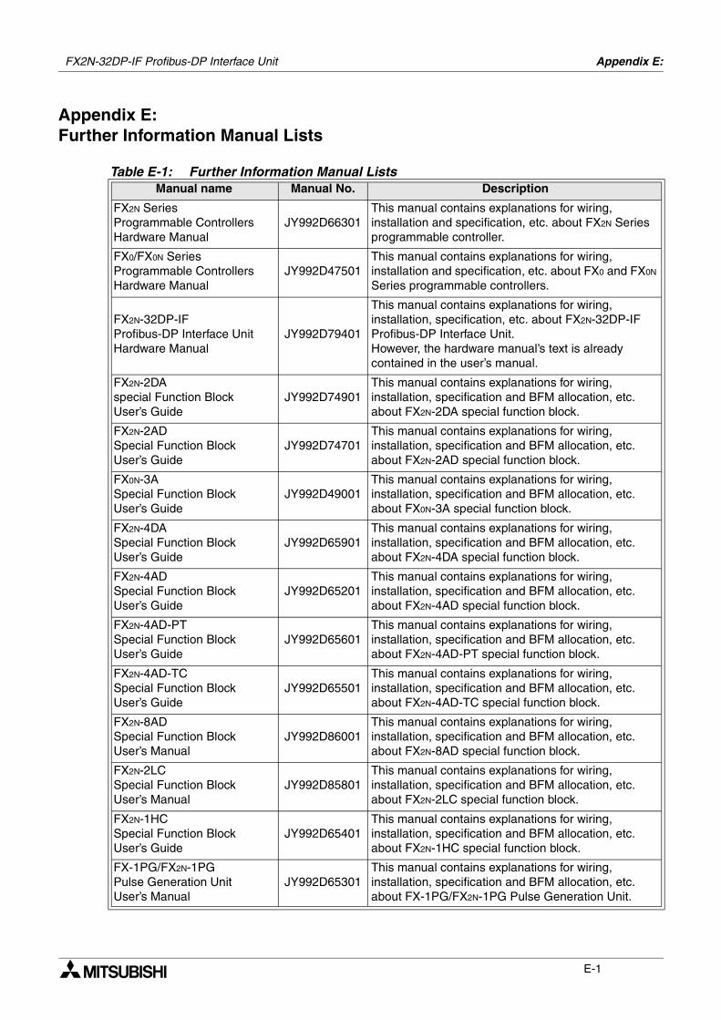
Appendix E:
E-1
Appendix E:Further Information Manual Lists
Table E-1: Further Information Manual ListsManual name Manual No. Description
FX2N SeriesProgrammable Controllers Hardware Manual
JY992D66301This manual contains explanations for wiring, installation and specification, etc. about FX2N Series programmable controller.
FX0/FX0N SeriesProgrammable Controllers Hardware Manual
JY992D47501This manual contains explanations for wiring, installation and specification, etc. about FX0 and FX0N Series programmable controllers.
FX2N-32DP-IF Profibus-DP Interface Unit Hardware Manual
JY992D79401
This manual contains explanations for wiring, installation, specification, etc. about FX2N-32DP-IF Profibus-DP Interface Unit.However, the hardware manual’s text is already contained in the user’s manual.
FX2N-2DAspecial Function BlockUser’s Guide
JY992D74901This manual contains explanations for wiring, installation, specification and BFM allocation, etc. about FX2N-2DA special function block.
FX2N-2ADSpecial Function BlockUser’s Guide
JY992D74701This manual contains explanations for wiring, installation, specification and BFM allocation, etc. about FX2N-2AD special function block.
FX0N-3ASpecial Function BlockUser’s Guide
JY992D49001This manual contains explanations for wiring, installation, specification and BFM allocation, etc. about FX0N-3A special function block.
FX2N-4DASpecial Function BlockUser’s Guide
JY992D65901This manual contains explanations for wiring, installation, specification and BFM allocation, etc. about FX2N-4DA special function block.
FX2N-4ADSpecial Function BlockUser’s Guide
JY992D65201This manual contains explanations for wiring, installation, specification and BFM allocation, etc. about FX2N-4AD special function block.
FX2N-4AD-PTSpecial Function BlockUser’s Guide
JY992D65601This manual contains explanations for wiring, installation, specification and BFM allocation, etc. about FX2N-4AD-PT special function block.
FX2N-4AD-TCSpecial Function BlockUser’s Guide
JY992D65501This manual contains explanations for wiring, installation, specification and BFM allocation, etc. about FX2N-4AD-TC special function block.
FX2N-8ADSpecial Function BlockUser’s Manual
JY992D86001This manual contains explanations for wiring, installation, specification and BFM allocation, etc. about FX2N-8AD special function block.
FX2N-2LCSpecial Function BlockUser’s Manual
JY992D85801This manual contains explanations for wiring, installation, specification and BFM allocation, etc. about FX2N-2LC special function block.
FX2N-1HCSpecial Function BlockUser’s Guide
JY992D65401This manual contains explanations for wiring, installation, specification and BFM allocation, etc. about FX2N-1HC special function block.
FX-1PG/FX2N-1PG Pulse Generation UnitUser’s Manual
JY992D65301This manual contains explanations for wiring, installation, specification and BFM allocation, etc. about FX-1PG/FX2N-1PG Pulse Generation Unit.
FX2N-32DP-IF Profibus-DP Interface Unit
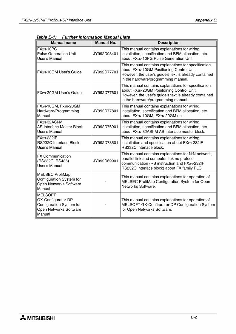
FX2N-32DP-IF Profibus-DP Interface Unit Appendix E:
E-2
FX2N-10PG Pulse Generation UnitUser’s Manual
JY992D93401This manual contains explanations for wiring, installation, specification and BFM allocation, etc. about FX2N-10PG Pulse Generation Unit.
FX2N-10GM User’s Guide JY992D77701
This manual contains explanations for specification about FX2N-10GM Positioning Control Unit.However, the user’s guide’s text is already contained in the hardware/programming manual.
FX2N-20GM User’s Guide JY992D77601
This manual contains explanations for specification about FX2N-20GM Positioning Control Unit.However, the user’s guide’s text is already contained in the hardware/programming manual.
FX2N-10GM, Fx2N-20GM Hardware/Programming Manual
JY992D77801This manual contains explanations for wiring, installation, specification and BFM allocation, etc. about FX2N-10GM, FX2N-20GM unit.
FX2N-32ASI-M AS-interface Master Block User’s Manual
JY992D76901This manual contains explanations for wiring, installation, specification and BFM allocation, etc. about FX2N-32ASI-M AS-interface master block.
FX2N-232IF RS232C Interface Block User’s Manual
JY992D73501This manual contains explanations for wiring, installation and specification about FX2N-232IF RS232C interface block.
FX Communication (RS232C, RS485) User’s Manual
JY992D69901
This manual contains explanations for N:N network, parallel link and computer link no protocol communication (RS instruction and FX2N-232IF RS232C interface block) about FX family PLC.
MELSEC ProfiMap Configuration System for Open Networks Software Manual
-This manual contains explanations for operation of MELSEC ProfiMap Configuration System for Open Networks Software.
MELSOFTGX-Configurator-DP Configuration System for Open Networks Software Manual
-This manual contains explanations for operation of MELSOFT GX-Confirarater-DP Configuration System for Open Networks Software.
Table E-1: Further Information Manual ListsManual name Manual No. Description


HEADQUARTERS
MITSUBISHI ELECTRIC
EUROPE B.V.German BranchGothaer Straße 8D-40880 RatingenPhone: +49 (0) 21 02 / 486-0Fax: +49 (0) 21 02 / 4 86-11 20E-Mail: [email protected]
MITSUBISHI ELECTRIC
EUROPE B.V.French Branch25, Boulevard des BouvetsF-92741 Nanterre CedexPhone: +33 1 55 68 55 68Fax: +33 1 55 68 56 85E-Mail: [email protected]
MITSUBISHI ELECTRIC
EUROPE B.V.UK BranchTravellers LaneGB-Hatfield Herts. AL10 8 XBPhone: +44 (0) 1707 / 27 61 00Fax: +44 (0) 1707 / 27 86 95
MITSUBISHI ELECTRIC
EUROPE B.V.Italian BranchVia Paracelso 12I-20041 Agrate Brianza (MI)Phone: +39 (0) 39 6053 1Fax: +39 (0) 39 6053 312E-Mail: [email protected]
MITSUBISHI ELECTRIC
EUROPE B.V.Spanish BranchCarretera de Rubí 76-80E-08190 Sant Cugat del VallésPhone: +34 9 3 / 565 3131Fax: +34 9 3 / 589 2948E-Mail: [email protected]
MITSUBISHI ELECTRIC
CORPORATIONOffice Tower “Z” 14 F8-12,1 chome, Harumi Chuo-KuTokyo 104-6212Phone: +81 3 / 622 160 60Fax: +81 3 / 622 160 75
MITSUBISHI ELECTRIC
AUTOMATION500 Corporate Woods ParkwayVernon Hills, IL 60061Phone: +1 847 / 478 21 00Fax: +1 847 / 478 22 83
EUROPEAN REPRESENTATIVES
GEVA
Wiener Straße 89A-2500 BadenPhone: +43 (0) 2252 / 85 55 20Fax: +43 (0) 2252 / 488 60E-mail: [email protected]
Getronics B.V.
Pontbeeklaan 43B-1731 Asse-ZellikPhone: +32 (0) 2 / 467 17 51Fax: +32 (0) 2 / 467 17 45E-Mail: [email protected]
TELECON CO.
4, A. Ljapchev Blvd.BG-1756 SofiaPhone: +359 (0) 2 / 97 44 05 8Fax: +359 (0) 2 / 97 44 06 1E-Mail: —
INEA CR d.o.o.
Drvinje 63HR-10000 ZagrebPhone: +385 (0)1/ 36 67 140Fax: +385 (0)1/ 36 67 140E-mail: —
AutoCont s.r.o.
Nemocnicni 12CZ-702 00 Ostrava 2Phone: +420 (0) 69 / 615 21 11Fax: +420 (0) 69 / 615 25 62E-mail: [email protected]
louis poulsen
industri & automationGeminivej 32DK-2670 GrevePhone: +45 (0) 43 / 95 95 95Fax: +45 (0) 43 / 95 95 91E-Mail: [email protected]
UTU Elektrotehnika AS
Pärnu mnt.160iEE-11317 TallinnPhone: +372 (0) 6 / 51 72 80Fax: +372 (0) 6 / 51 72 88E-mail: [email protected]
Beijer Electronics OY
Ansatie 6aFIN-01740 VantaaPhone: +358 (0) 9 / 886 77 500Fax: +358 (0) 9 / 886 77 555E-mail: [email protected]
UTECO A.B.E.E.
5, Mavrogenous Str.GR-18542 PiraeusPhone: +30 10 / 42 10 050Fax: +30 10 / 42 12 033E-mail: —
Meltrade Automatika Kft.
55, Harmat St.HU-1105 BudapestPhone: +36 (0)1 / 2605 602Fax: +36 (0)1 / 2605 602E-mail: [email protected]
MITSUBISHI ELECTRIC
Westgate Business ParkIRL-Dublin 24Phone: +353 (0) 1 / 419 88 00Fax: +353 (0) 1 / 419 88 90E-mail: [email protected]
EUROPEAN REPRESENTATIVES
POWEL SIA
Lienes iela 28LV-1009 RigaPhone: +371 784 / 22 80Fax: +371 784 / 22 81E-mail: [email protected]
UTU POWEL UAB
Savanoriu pr. 187LT-2053 VilniusPhone: +370 (0) 232-2980Fax: +370 (0) 232-2980E-mail: [email protected]
Getronics
Industrial Automation B.V.Donauweg 2 BNL-1043 AJ AmsterdamPhone: +31 (0) 20 / 587 67 00Fax: +31 (0) 20 / 587 68 39E-Mail: [email protected]
Beijer Electronics AS
Teglverksveien 1N-3002 DrammenPhone: +47 (0) 32 / 24 30 00Fax: +47 (0) 32 / 84 85 77E-Mail: —
MPL Technology Sp. z o.o.
ul. Sliczna 36PL-31-444 KrakówPhone: +48 (0) 12 / 632 28 85Fax: +48 (0) 12 / 632 47 82E-mail: [email protected]
Sirius Trading & Services srl
Bd. Lacul Tei nr. 1 BRO-72301 Bucuresti 2Phone: +40 (0) 21 / 201 7147Fax: +40 (0) 1 / 201 7148E-mail: [email protected]
ACP Autocomp a.s.
Chalupkova 7SK-81109 BratislavaPhone: +421 (02) / 5292- 22 54, 55Fax: +421 (02) / 5292- 22 48E-mail: [email protected]
INEA d.o.o.
Stegne 11SI-1000 LjubljanaPhone: +386 (0) 1- 513 8100Fax: +386 (0) 1- 513 8170E-mail: [email protected]
Beijer Electronics AB
Box 426S-20124 MalmöPhone: +46 (0) 40 / 35 86 00Fax: +46 (0) 40 / 35 86 02E-Mail: —
ECONOTEC AG
Postfach 282CH-8309 NürensdorfPhone: +41 (0) 1 / 838 48 11Fax: +41 (0) 1 / 838 48 12E-Mail: [email protected]
GTS
Darülaceze Cad. No. 43A KAT: 2TR-80270 Okmeydani-IstanbulPhone: +90 (0) 212 / 320 1640Fax: +90 (0) 212 / 320 1649E-Mail: [email protected]
AFRICAN REPRESENTATIVE
CBI Ltd
Private Bag 2016ZA-1600 IsandoPhone: +27 (0) 11/ 928 2000Fax: +27 (0) 11/ 392 2354E-mail: [email protected]
MIDDLE EAST REPRESENTATIVE
ILAN & GAVISH LTD
24 Shenkar St., Kiryat ArieIL-49001 Petah-TiqvaPhone: +972 (0) 3 / 922 18 24Fax: +972 (0) 3 / 924 07 61E-mail: [email protected]
TEXEL Electronics LTD.
Box 6272IL-42160 NetanyaPhone: +972 (0) 9 / 863 08 91Fax: +972 (0) 9 / 885 24 30E-mail: [email protected]
EURASIAN REPRESENTATIVE
TEHNIKON
Oktjabrskaya 16/5, Ap 704BY-220030 MinskPhone: +375 (0) 17 / 22 75 704Fax: +375 (0) 17 / 22 76 669E-mail: [email protected]
AVTOMATIKA SEVER
Krapivnij Per. 5, Of. 402RUS-194044 St PetersburgPhone: +7 812 54 18 418Fax: +7 812 11 83 239E-mail: —
CONSYS
Promyshlennaya St. 42RUS-198099 St PetersburgPhone: +7 812 / 325 36 53Fax: +7 812 / 325 36 53E-mail: [email protected]
ICOS
Ryazanskij Prospekt, 8a, Office 100RUS-109428 MoscowPhone: +7 095 / 232 - 0207Fax: +7 095 / 232 - 0327E-mail: [email protected]
NPP Uralelektra
Sverdlova 11ARUS-620027 EkaterinburgPhone: +7 34 32 / 53 27 45Fax: +7 34 32 / 53 24 61E-mail: [email protected]
STC Drive Technique
Poslannikov per., 9, str.1RUS-107005 MoscowPhone: +7 095 / 786 21 00Fax: +7 095 / 786 21 01E-mail: [email protected]
JV-CSC Automation
15, Marina Raskovoyi St.U-02002 KievPhone: +380 44 / 238 83 16Fax: +380 44 / 238 83 17E-mail: [email protected]
INDUSTRIAL AUTOMATION
MITSUBISHI ELECTRIC
MITSUBISHI ELECTRIC
PLC
03/0
2-P
rinte
din
Ger
man
y
Gothaer Straße 8 Phone: +49 2102 486-0 Fax: +49 2102 486-7170 www.mitsubishi-automation.deD-40880 Ratingen Hotline: +49 1805 000-7650 [email protected] www.mitsubishi-automation.com


![PROFIBUS DP bus interface, PROFIBUS DP [BU 2700]...Sicherheit/PROFIBUS DP [BU 2700]/Bestimmungsgemäße Ver wendung PROFIBUS DP @ 8\mod_1461835577600_388.docx @ 2249429 @ 2 @ 1 2.1](https://img.pdfslide.net/doc/110x75/60b54c574bd00c04b50e633d/profibus-dp-bus-interface-profibus-dp-bu-2700-sicherheitprofibus-dp-bu.jpg)